JP7151142B2 - high frequency treatment - Google Patents
high frequency treatmentDownload PDFInfo
- Publication number
- JP7151142B2 JP7151142B2JP2018076776AJP2018076776AJP7151142B2JP 7151142 B2JP7151142 B2JP 7151142B2JP 2018076776 AJP2018076776 AJP 2018076776AJP 2018076776 AJP2018076776 AJP 2018076776AJP 7151142 B2JP7151142 B2JP 7151142B2
- Authority
- JP
- Japan
- Prior art keywords
- scissors
- pair
- inclined surface
- frequency treatment
- electrode region
- Prior art date
- Legal status (The legal status is an assumption and is not a legal conclusion. Google has not performed a legal analysis and makes no representation as to the accuracy of the status listed.)
- Active
Links
- 230000015572biosynthetic processEffects0.000claimsdescription7
- 210000001519tissueAnatomy0.000description28
- 210000000078clawAnatomy0.000description15
- 239000011248coating agentSubstances0.000description10
- 238000000576coating methodMethods0.000description10
- 230000002439hemostatic effectEffects0.000description6
- 210000003811fingerAnatomy0.000description4
- 230000002708enhancing effectEffects0.000description3
- 239000007769metal materialSubstances0.000description3
- 238000000034methodMethods0.000description3
- 239000004696Poly ether ether ketoneSubstances0.000description2
- 229910010293ceramic materialInorganic materials0.000description2
- 229920002530polyetherether ketonePolymers0.000description2
- QNRATNLHPGXHMA-XZHTYLCXSA-N(r)-(6-ethoxyquinolin-4-yl)-[(2s,4s,5r)-5-ethyl-1-azabicyclo[2.2.2]octan-2-yl]methanol;hydrochlorideChemical compoundCl.C([C@H]([C@H](C1)CC)C2)CN1[C@@H]2[C@H](O)C1=CC=NC2=CC=C(OCC)C=C21QNRATNLHPGXHMA-XZHTYLCXSA-N0.000description1
- OKTJSMMVPCPJKN-UHFFFAOYSA-NCarbonChemical compound[C]OKTJSMMVPCPJKN-UHFFFAOYSA-N0.000description1
- GWEVSGVZZGPLCZ-UHFFFAOYSA-NTitan oxideChemical compoundO=[Ti]=OGWEVSGVZZGPLCZ-UHFFFAOYSA-N0.000description1
- 229910052799carbonInorganic materials0.000description1
- 239000000470constituentSubstances0.000description1
- 238000010586diagramMethods0.000description1
- 230000000694effectsEffects0.000description1
- -1fluororesinSubstances0.000description1
- 239000011810insulating materialSubstances0.000description1
- 230000003902lesionEffects0.000description1
- 239000002184metalSubstances0.000description1
- 229910052751metalInorganic materials0.000description1
- 210000004400mucous membraneAnatomy0.000description1
- 238000002271resectionMethods0.000description1
- 229910052710siliconInorganic materials0.000description1
- 239000010703siliconSubstances0.000description1
- 229910001220stainless steelInorganic materials0.000description1
- 239000010935stainless steelSubstances0.000description1
- 210000003813thumbAnatomy0.000description1
- OGIDPMRJRNCKJF-UHFFFAOYSA-Ntitanium oxideInorganic materials[Ti]=OOGIDPMRJRNCKJF-UHFFFAOYSA-N0.000description1
- 238000004804windingMethods0.000description1
Images


Landscapes
- Surgical Instruments (AREA)
Description
Translated fromJapanese本発明は、高周波処置具に関する。 The present invention relates to a high-frequency treatment instrument.
体腔内で生体組織を切開する処置(病変部位を切除する処置を含む)を行うための医療用器具として、内視鏡の鉗子孔に挿入して用いられる高周波処置具が知られている。 2. Description of the Related Art A high-frequency surgical instrument that is used by being inserted into a forceps hole of an endoscope is known as a medical instrument for performing a procedure of incising a body tissue (including a procedure of excising a lesion site) within a body cavity.
例えば、特許文献1には、開閉可能な一対のハサミ部を先端部に備える高周波処置具について記載されている。 For example, Patent Literature 1 describes a high-frequency treatment instrument having a pair of scissors that can be opened and closed at its distal end.
しかしながら、本願発明者の検討によれば、特許文献1の技術では、生体組織の止血性について、なお改善の余地がある。 However, according to the studies of the inventors of the present application, the technique of Patent Document 1 still has room for improvement in terms of the hemostatic properties of living tissue.
本発明は、上記の課題に鑑みてなされたものであり、生体組織の止血性がより良好となる構造の高周波処置具を提供するものである。 SUMMARY OF THE INVENTION The present invention has been made in view of the above problems, and provides a high-frequency treatment instrument having a structure that improves the hemostatic property of living tissue.
本発明は、一対のハサミ部を有していて生体組織の切開に用いられる高周波処置具用ナイフを、先端部に備える医療用の高周波処置具であって、
前記一対のハサミ部の各々は、長尺な板状に形成されており、
前記一対のハサミ部の基端部どうしが、これらハサミ部の板面方向に対して交差する回動軸において相互に軸支されており、
前記一対のハサミ部は、互いに近づく方向に回動することにより前記生体組織を剪断可能に構成されており、
前記一対のハサミ部の各々は、刃面と、互いに摺接する摺接面と、前記摺接面に対する裏面である外側面と、前記外側面と前記刃面との間に位置している傾斜面と、を有し、
前記傾斜面は、前記摺接面側から前記外側面側に向けて、他方の前記ハサミ部から遠ざかる方向に傾斜しており、
前記一対のハサミ部の各々の表面は、非導電性層の形成領域と、前記非導電性層が非形成となっている電極領域と、を含み、
前記一対のハサミ部の少なくとも一方について、前記電極領域が、前記刃面と前記傾斜面とに形成されている高周波処置具を提供するものである。The present invention is a medical high-frequency treatment instrument provided with a knife for high-frequency treatment instrument having a pair of scissors and used for incising living tissue at the distal end thereof,
Each of the pair of scissors is formed in a long plate shape,
base ends of the pair of scissors are mutually supported by a rotation shaft that intersects the plate surface direction of the scissors;
The pair of scissors is configured to be able to shear the living tissue by rotating in a direction toward each other,
Each of the pair of scissors includes a blade surface, a sliding contact surface that is in sliding contact with each other, an outer surface that is the back surface of the sliding contact surface, and an inclined surface that is positioned between the outer surface and the blade surface. and
the inclined surface is inclined from the sliding contact surface side toward the outer side surface side in a direction away from the other scissor portion,
Each surface of the pair of scissors includes a non-conductive layer formation region and an electrode region where the non-conductive layer is not formed,
A high-frequency treatment instrument is provided in which the electrode region is formed on the blade surface and the inclined surface for at least one of the pair of scissors.
本発明によれば、生体組織の止血性がより良好となる。 According to the present invention, the hemostatic property of living tissue is improved.
以下、本発明の実施形態について、図面を用いて説明する。なお、すべての図面において、同様の構成要素には同一の符号を付し、適宜に説明を省略する。
本実施形態に係る医療用の高周波処置具の各種の構成要素は、個々に独立した存在である必要はなく、複数の構成要素が一個の部材として形成されていること、一つの構成要素が複数の部材で形成されていること、ある構成要素が他の構成要素の一部であること、ある構成要素の一部と他の構成要素の一部とが重複していること、等を許容する。BEST MODE FOR CARRYING OUT THE INVENTION Hereinafter, embodiments of the present invention will be described with reference to the drawings. In addition, in all the drawings, the same reference numerals are given to the same constituent elements, and the description thereof will be omitted as appropriate.
Various components of the medical high-frequency treatment device according to the present embodiment do not need to exist independently of each other. It is allowed that it is formed from the members of the .
〔第1実施形態〕
先ず、図1から図8を用いて第1実施形態を説明する。
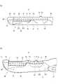
図2及び図3に示す側面図では、シース70において図示した範囲のうち、基端側の部分については、中心線に沿った側断面を示している。
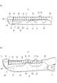
図5(a)、図6(a)、図6(b)、図7(a)及び図7(b)の各々においては、ハサミ部10における電極の形成領域(電極領域19)にドット状のハッチングを付している。図5(a)、図6(a)、図6(b)、図7(a)及び図7(b)の各々において、ドット状のハッチングが付されていない領域は、絶縁性被膜12(非導電性層)の形成領域である。ただし、第1軸支孔21の内部及び第2軸支孔22の内部については、絶縁性被膜12が非形成となっていても良い。[First embodiment]
First, a first embodiment will be described with reference to FIGS. 1 to 8. FIG.
The side views shown in FIGS. 2 and 3 show a side cross section along the center line of the portion on the proximal side of the illustrated range of the
5(a), 6(a), 6(b), 7(a), and 7(b), dots are formed in the electrode formation region (electrode region 19) of the
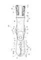
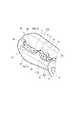
図1に示すように、本実施形態に係る高周波処置具200は、医療用の高周波処置具200である。高周波処置具200は、一対のハサミ部10を有していて生体組織の切開に用いられる高周波処置具用ナイフ100を、当該高周波処置具200の先端部に備えている。
高周波処置具200は、当該高周波処置具200の高周波処置具用ナイフ100を内視鏡(不図示)の鉗子孔に挿入して用いられる。As shown in FIG. 1, a high-
The high-
なお、一対のハサミ部10のうちの一方のハサミ部10をハサミ部10aと称し、他方のハサミ部10をハサミ部10bと称する。
一対のハサミ部10の各々は、長尺な板状に形成されている(図7(a)、図7(b)参照)。
図2から図4に示すように、一対のハサミ部10の基端部どうしが、これらハサミ部10の板面方向に対して交差する回動軸(軸部材61)において相互に軸支されている。
一対のハサミ部10は、互いに近づく方向に回動することにより生体組織を剪断可能に構成されている。
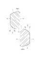
一対のハサミ部10の各々は、刃面13と、互いに摺接する摺接面14と、摺接面14に対する裏面である外側面15と、外側面15と刃面13との間に位置している傾斜面16と、刃面13に対する反対側の面である背面17と、を有している。One
Each of the pair of
As shown in FIGS. 2 to 4, the base ends of the pair of
The pair of
Each of the pair of
傾斜面16は、摺接面14側から外側面15側に向けて、他方のハサミ部10から遠ざかる方向に傾斜している。すなわち、図8に示すように、ハサミ部10aの傾斜面16は、当該ハサミ部10aの摺接面14側(図8における左側)から外側面15側(図8における右側)に向けて下り傾斜しており、ハサミ部10bの傾斜面16は、当該ハサミ部10bの摺接面14側(図8における右側)から外側面15(図8における左側)に向けて上り傾斜している。
なお、換言すれば、傾斜面16は、刃面13側から外側面15側に向けて、他方のハサミ部10から遠ざかる方向に傾斜している。すなわち、図8に示すように、ハサミ部10aの傾斜面16は、当該ハサミ部10aの刃面13側から外側面15側に向けて下り傾斜しており、ハサミ部10bの傾斜面16は、当該ハサミ部10bの刃面13側から外側面15に向けて上り傾斜している。The
In other words, the
一対のハサミ部10の各々の表面は、非導電性層(絶縁性被膜12)の形成領域と、非導電性層が非形成となっている電極領域19とを含んでいる。
そして、一対のハサミ部10の少なくとも一方について、電極領域19が、刃面13と傾斜面16とに形成されている。本実施形態の場合、一対のハサミ部10の各々について、電極領域19が、刃面13と傾斜面16とに形成されている。Each surface of the pair of
At least one of the pair of
本実施形態に係る高周波処置具200によれば、一対のハサミ部10の少なくとも一方について、電極領域19が、刃面13だけでなく傾斜面16にも形成されている。このため、生体組織を切開する際に、刃面13とともに生体組織に触れる傾斜面16の電極領域19から生体組織に電流を付与できるので、生体組織の止血性が高まる。 According to the high-
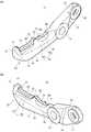
図7(a)及び図7(b)に示すように、一対のハサミ部10の各々は、当該ハサミ部10における基端側の部分である基端片20と、当該ハサミ部10における先端側の部分である先端片30と、を有する。
基端片20の先端部には、当該基端片20を厚み方向に貫通した第1軸支孔21が形成されている。一対のハサミ部10の第1軸支孔21に共通の軸部材61(図2から図4)が挿通されて、一対のハサミ部10が軸支されている。
先端片30は、ハサミ部10において第1軸支孔21よりも先端側の部分である。
基端片20の基端部には、当該基端片20を厚み方向に貫通した第2軸支孔22が形成されている。As shown in FIGS. 7(a) and 7(b), each of the pair of
A first
The
A second
図1に示すように、高周波処置具200は、長尺な操作ワイヤ68と、操作ワイヤ68の先端に設けられた高周波処置具用ナイフ100と、操作ワイヤ68が収容された可撓性のシース70と、シース70の基端側に設けられて操作ワイヤ68の基端が接続された手元操作部90と、を備えている。 As shown in FIG. 1, the high-
シース70は、操作ワイヤ68を収容する長尺かつ管状の部材である。本実施形態の場合、シース70は、ステンレス線等の導電性ワイヤを密着巻回して作製された、金属製のコイル71(図2、図3)により構成されている。シース70の外表面には絶縁性被膜72(図2、図3)が密着して設けられている。ただし、シース70としては、金属製のコイル71に代えて絶縁性の管状部材(チューブ)を用いてもよい。 The
手元操作部90は、一対のハサミ部10の開閉操作を行うためのものであり、高周波処置具200における基端側に配置されている。
手元操作部90は、例えば、操作ワイヤ68が挿通された軸部95と、この軸部95の基端部に設けられた指掛リング92と、操作ワイヤ68の基端が連結されて軸部95に対して進退移動するスライダ93と、回転操作部94と、を備えている。操作ワイヤ68は軸部95に対して摺動可能に挿通されている。ユーザは、指掛リング92に例えば親指を挿入し、スライダ93を他の2本の指で挟んで軸部95の長手方向に沿って進退駆動する。これにより、操作ワイヤ68は手元操作部90に対して前進または後退する。シース70の基端は手元操作部90に固定され、操作ワイヤ68はシース70に対して進退可能に挿通されているため、スライダ93の進退移動に連動して操作ワイヤ68の先端はシース70に対して前進または後退する。これにより、後述するように、高周波処置具用ナイフ100の進退部67(図2、図3)が進退駆動されて、一対のハサミ部10が開閉する。
一対のハサミ部10の回転軸の軸方向は、ハサミ部10の板面に対して直交する方向(ハサミ部10の厚み方向)であり、一対のハサミ部10が開閉する際には、一対のハサミ部10の摺接面14どうしが摺動する。The
The
The axial direction of the rotating shaft of the pair of
図1に示すように、手元操作部90は給電部91を備えている。給電部91は一対のハサミ部10に高周波電流を印加するための端子である。給電部91には、電源ケーブルを介して高周波電源(不図示)が接続される。高周波処置具用ナイフ100を構成する一対のハサミ部10、リンク片65、66(後述)および進退部67(後述)は、いずれも導電性の金属材料で作製されている。また、操作ワイヤ68も導電性の金属材料で作製されている。このため、給電部91に入力された高周波電流は一対のハサミ部10に印加される。 As shown in FIG. 1 , the
回転操作部94には操作ワイヤ68が接続されており、回転操作部94を軸部95のまわりに軸回転させることで、スライダ93に基端が固定された操作ワイヤ68はシース70の内部で回転する。これにより、高周波処置具用ナイフ100を所望の向きに指向させることができる。
回転操作部94は給電部91に対して回転可能に取り付けられており、給電部91と高周波電源(図示せず)とを連結する電源ケーブル(図示せず)を下方に垂下させた状態で回転操作部94を軸部95の周りに回転操作することができる。An
The
なお、本実施形態に代えて、スライダ93を軸部95のまわりに軸回転可能に構成して、スライダ93が回転操作部94の機能を兼ねるようにしてもよい。すなわち、スライダ93を軸部95の長手方向に沿って進退駆動することで操作ワイヤ68を進退させて高周波処置具用ナイフ100を開閉操作し、またスライダ93を軸部95のまわりに軸回転させることで高周波処置具用ナイフ100を回転させて所望の向きに指向させるように構成してもよい。
また、回転操作部94を軸部95に設け、給電部91に対して回転可能な構成としてもよい。この場合、スライダ93を軸部95の周りに軸回転可能に構成してもよい。Instead of this embodiment, the
Further, the
図2から図4に示すように、高周波処置具用ナイフ100は、板状の一対のハサミ部10と、これらハサミ部10を開閉可能に軸支している軸部材61と、2枚のリンク片65、66と、進退部67と、保持枠80と、を備えている。
軸部材61の軸方向は、図2及び図3の紙面に対して直交する方向であり、図4における上下方向である。また、軸部材61の軸方向は、一対のハサミ部10どうしの重なり方向であり、言い換えると一対のハサミ部10の厚み方向である。
一対のハサミ部10は、操作ワイヤ68の押し引きにより開閉駆動される。操作ワイヤ68は、ステンレス鋼などの導電性の金属材料で作製されている。As shown in FIGS. 2 to 4, the high-frequency
The axial direction of the
The pair of
進退部67は、操作ワイヤ68の先端に、当該操作ワイヤ68と一体に連結されている。進退部67には軸部材64により2枚のリンク片65、66の基端部が回動可能に連結されている。さらに、リンク片65の先端部には軸部材63により一方のハサミ部10(ハサミ部10a)の基端片20が回動可能に連結されている。すなわち、一方のハサミ部10aの第2軸支孔22とリンク片65の先端部とに軸部材63が挿通されることにより、ハサミ部10aとリンク片65とが相互に回転可能に軸支されている。同様に、リンク片66の先端部には軸部材62により他方のハサミ部10(ハサミ部10b)の基端片20が回動可能に連結されている。すなわち、他方のハサミ部10bの第2軸支孔22とリンク片66の先端部とに軸部材62が挿通されることにより、ハサミ部10bとリンク片66とが相互に回転可能に軸支されている。
各軸部材62、63、64の軸方向は、軸部材61の軸方向に対して平行な方向である。
一対のハサミ部10およびリンク片65、66は、図2及び図3に示す平面内(軸部材61の軸方向に対して直交する平面内)で相対的に回動する。
一対のハサミ部10の基端片20と、リンク片65、66とにより菱形の四節リンクが構成されている。
なお、軸部材62、63は、軸部材64よりも先端側に位置しており、軸部材61は、軸部材62、63よりも先端側に位置している。The advance/
The axial direction of each of the
The pair of
A rhombic four-bar link is formed by the
The
図7(a)及び図7(b)に示すように、基端片20の外側面には段差部23が形成されている。基端片20において段差部23よりも基端側の部位は、段差部23よりも先端側の部位よりも薄くなっている。
図4に示すように、基端片20において段差部23よりも基端側の部位と先端側の部位との厚みの差は、リンク片65、66の厚みよりも若干大きい程度に設定されているか、又は、リンク片65、66の厚みと同等に設定されている。As shown in FIGS. 7A and 7B, a stepped
As shown in FIG. 4, the difference in thickness between the portion of the
保持枠80はシース70の先端に固定されている。
保持枠80は、シース70の先端に固定されている基端部81と、基端部81から先端側に突出している一対のブラケット82と、を備えている。
一対のブラケット82の各々は、例えば板状に形成されている。
一対のハサミ部10は、一対のブラケット82の先端部に対して、軸部材61により軸支されている。すなわち、軸部材61が、一対のハサミ部10の各々の基端片20の第1軸支孔21と一対のブラケット82とに挿通されることによって、一対のハサミ部10の基端片20が一対のブラケット82によって軸支されている。
一対のブラケット82どうしの間隙において、一対のハサミ部10の基端片20と、リンク片65、66がそれぞれ回転可能となっているとともに、進退部67においてシース70から先端側に突出している部分が進退可能となっている。
更に、ブラケット82が基端部81に対してシース70の軸周りに回転可能となっているか、又は、ブラケット82がシース70に対してシース70の軸周りに回転可能となっている。A holding
The holding
Each of the pair of
The pair of
In the gap between the pair of
Further, either the
図2に示すように、操作ワイヤ68および進退部67が基端側(図2における右方)に牽引されると、一対のハサミ部10が閉状態となる。逆に、図3に示すように、操作ワイヤ68および進退部67が先端側(図3における左方)に押し出されると、一対のハサミ部10が開状態となる。 As shown in FIG. 2, when the
一対のハサミ部10の各々の表面には絶縁性被膜12(非導電性層)が形成されている。絶縁性被膜12は、少なくとも、先端片30の表面のうち、電極領域19の形成領域を除く全体に形成されている。
絶縁性被膜12は、たとえばフッ素樹脂、ポリエーテルエーテルケトン(PEEK)、ダイヤモンドライクカーボン(DLC:Diamond-Like Carbon)、又はセラミック材料(酸化チタン系やシリコン系等のセラミック材料)などの絶縁性材料をハサミ部10の表面にコーティングすることにより形成することができる。
電極領域19は、先端片30において絶縁性被膜12が非形成となっている線状の部分である。一対のハサミ部10は、給電部91から同位相の高周波電圧が印加されてモノポーラ型の高周波電極となる。一対のハサミ部10で生体組織を把持した状態で高周波電流を一対のハサミ部10に印加することにより、生体組織は焼灼されて切開される。なお、本実施形態に代えて、一対のハサミ部10の一方をアクティブ電極とし、他方をリターン電極とするバイポーラ型の高周波処置具200としてもよい。An insulating coating 12 (non-conductive layer) is formed on the surface of each of the pair of
The insulating
The
一対のハサミ部10の形状は、互いに同一であってもよいし、互いに異なっていてもよい。本実施形態の場合、一対のハサミ部10は互いに同一形状である。
以下、図5(a)から図8を用いて、ハサミ部10の形状の詳細を説明する。The shape of the pair of
The details of the shape of the
上述のように、ハサミ部10は、刃面13と、摺接面14と、摺接面14に対する裏面である外側面15と、外側面15と刃面13との間に位置している傾斜面16とを有している(図8参照)。
摺接面14と外側面15とは、例えば、互いに平行に配置されている。
本実施形態の場合、刃面13は、例えば、摺接面14及び外側面15の双方に対して直交している。すなわち、刃面13は、ハサミ部10の回転軸である軸部材61の軸方向に対して平行に配置されている。
傾斜面16は、刃面13と外側面15との双方に対して傾斜している。
本実施形態の場合、傾斜面16は、外側面15側に位置する第1傾斜面161と、刃面13側に位置する第2傾斜面162と、を含んで構成されている。
刃面13と第1傾斜面161とのなす角度よりも、刃面13と第1傾斜面161とのなす角度が大きい。また、外側面15と第2傾斜面162とのなす角度よりも、外側面15と第1傾斜面161とのなす角度の方が大きい。As described above, the
The sliding
In the case of this embodiment, the
The
In this embodiment, the
The angle formed by the
ハサミ部10の先端片30の先端部(図5(a)における先端片30の左端部)には、先端爪部40が形成されている。先端爪部40は、閉じ方向に突出している。閉じ方向とは一方のハサミ部10から他方のハサミ部10bに向かう方向であり、その反対方向を開き方向と呼称する。先端爪部40は、図5(a)において上方に突出している。
先端爪部40は、生体組織に食い込む突起である。
先端片30において先端爪部40よりも基端側(図5(a)における右側)の部分における閉じ方向側の端縁(エッジ)、すなわち図5(a)における先端片30の上縁に沿って、刃面13が形成されている。
一対のハサミ部10の先端爪部40により生体組織を挟持して生体組織の脱落を抑止した状態で、一対のハサミ部10の刃面13により生体組織を剪断し切開することができるようになっている。A
The
Along the edge of the
In a state in which the living tissue is clamped by the
本実施形態の場合、ハサミ部10は、図5(a)に示すように、当該ハサミ部10の長手方向における中間部において他方のハサミ部10側に向けて突出している中間突起部51と、当該ハサミ部10の長手方向において中間突起部51の基端側及び先端側にそれぞれ隣接して配置されていて他方のハサミ部から遠ざかる側に向けて窪んでいる凹部55、56とを備えている。基端側の凹部55の基端側に隣接して配置されていて凹部55よりも高段になっている部分は、基端側高段部58と称する。
先端片30の閉じ方向側の端縁には、先端片30の先端側から順に、先端爪部40、凹部56、中間突起部51、凹部55及び基端側高段部58が配置されている。In the case of this embodiment, as shown in FIG. 5(a), the
At the edge of the
刃面13は、中間突起部51の頂面52と、凹部55、56の表面とを含む。より詳細には、本実施形態の場合、刃面13は、凹部56、中間突起部51及び凹部55に亘って連続的に形成されている。
そして、刃面13の全域(凹部55の表面、中間突起部51の頂面52及び凹部56の表面の全域)に亘り、電極領域19が形成されている。The
An
先端爪部40、凹部56、中間突起部51、凹部55及び基端側高段部58の各々は、ハサミ部10の厚み方向において所定の幅を有している。
例えば、先端爪部40、凹部56、中間突起部51及び凹部55に亘る範囲では、ハサミ部10の厚み方向における幅寸法が略一定となっている(図6(a)、図6(b)参照)。
凹部56及び凹部55の各々は、先端片30の先基端方向(図6(a)における左右方向)に長尺に形成されている。Each of the
For example, the width dimension in the thickness direction of the
Each of the recessed
刃面13は、凹部55の底面、凹部56の底面及び中間突起部51の頂面52において、例えば、それぞれ平坦に形成されている。凹部55の底面、凹部56の底面及び中間突起部51の頂面52は、例えば、互いに略平行に配置されている。凹部56の底面及び凹部55の底面は、先端片30の先基端方向に延在している。 The
更に、凹部56と外側面15との間の傾斜面16にも電極領域19が形成されている(図6(a)から図7(b)参照)。すなわち、中間突起部51よりもハサミ部10の先端側の凹部56と、外側面15と、の間の傾斜面16に電極領域19が形成されている。
より詳細には、例えば、凹部56と外側面15との間の傾斜面16のうち、凹部56側(刃面13側)の第2傾斜面162の一部分(凹部56側の部分)に電極領域19が形成されている。Further, an
More specifically, for example, of the
また、本実施形態の場合、電極領域19が、刃面13と傾斜面16とに亘って連続的に形成されている。
凹部56と外側面15との間の第2傾斜面162の電極領域19は、凹部56の長手方向の全域に亘って連続的に配置されている。Moreover, in the case of this embodiment, the
The
一方、凹部55と外側面15との間の傾斜面16には、電極領域19が形成されていない。
すなわち、中間突起部51の頂面52よりもハサミ部10の先端側の傾斜面16と、中間突起部51の頂面52よりもハサミ部10の基端側の傾斜面16とのうち、中間突起部51の頂面52よりもハサミ部10の先端側の傾斜面16に選択的に電極領域19が形成されている。
ハサミ部10の先端側の部分ほど、生体組織の切除の際に粘膜の下に潜り込んで切除に用いられるため、電極領域19から生体組織に流れる電流を大きくして止血性を高める効果をより求められるという事情に対し、その要求を満たすことができる。On the other hand, the
That is, between the
Since the part closer to the tip side of the
なお、第2傾斜面162は、例えば、凹部56と外側面15との間、並びに、凹部55と外側面15との間に形成されており、頂面52と外側面15との間には形成されていない。すなわち、例えば、頂面52と外側面15との間には第1傾斜面161が形成されているのみとなっている。
一方、第1傾斜面161は、凹部56と外側面15との間、頂面52と外側面15との間、及び、凹部55と外側面15との間に亘って連続的に存在している。The second
On the other hand, the first
また、中間突起部51における外側面15側の側面における傾斜面16には、絶縁性被膜12が形成されており、電極領域19は非形成となっている。
すなわち、傾斜面16は中間突起部51にも形成されており、中間突起部51の傾斜面16には、非導電性層(絶縁性被膜12)が形成されており、電極領域19は非形成となっている。Also, the insulating
That is, the
また、例えば、先端爪部40において先端側を向く面である先端面42、先端爪部40の頂面43及び先端爪部40の側面にも、それぞれ絶縁性被膜12が形成されており、先端爪部40の先端面42、頂面43及び側面には、電極領域19が非形成となっている。
一方、先端爪部40において基端側を向く面である基端面41には、絶縁性被膜12が非形成となっており、電極領域19が形成されている。基端面41の電極領域19は、凹部56の電極領域19と連続している(図7(b)参照)。Further, for example, the insulating
On the other hand, the insulating
一対のハサミ部10の少なくとも一方のハサミ部10には、ストッパー部11が形成されている。一対のハサミ部10の閉動作は、ストッパー部11が他方のハサミ部10の刃面13に当接することで規制されるようになっている。
本実施形態の場合、一対のハサミ部10の各々にストッパー部11が形成されており、ハサミ部10aのストッパー部11がハサミ部10bの刃面13に当接するとともに、ハサミ部10bのストッパー部11がハサミ部10aの刃面13に当接することで、一対のハサミ部10の閉動作が規制されるようになっている。A
In the case of this embodiment, a
ストッパー部11は、ハサミ部10において、図5(b)に示す摺接面14に形成されている。ストッパー部11において、他方のハサミ部10側を向く部位は、平坦面11aとなっている。
ストッパー部11は、例えば、凹部55の長手方向における中間部に配置されている。
平坦面11aは、例えば、凹部55の底面と面一に配置されている。そして、一対のハサミ部10が閉じた際には、平坦面11aが他方のハサミ部10の凹部55の底面に対して面接触することで、一対のハサミ部10の閉動作が規制される。
例えば、平坦面11aにも絶縁性被膜12が非形成となっていて、平坦面11aも電極領域19の一部分となっている。The
The
The
For example, the insulating
ストッパー部11の平坦面11aは、刃面13には含まれないものとする。
先端爪部40の基端面41、凹部56の表面、中間突起部51の頂面52、凹部55の表面、凹部56と外側面15との間の第2傾斜面162の一部分及びストッパー部11の平坦面11aを除き、先端片30の全体の表面に絶縁性被膜12が形成されている。
なお、中間突起部51における先端側の傾斜面は、凹部56の表面の一部分であるものとし、中間突起部51における基端側の傾斜面は、凹部55の表面の一部分であるものとする。The
The
It is assumed that the tip-side inclined surface of the
以上のような第1実施形態によれば、一対のハサミ部10の少なくとも一方について、電極領域19が、刃面13だけでなく傾斜面16にも形成されている。このため、生体組織を切開する際に、刃面13とともに生体組織に触れる傾斜面16の電極領域19から生体組織に電流を付与できるので、生体組織の止血性が高まる。
しかも、生体組織に触れやすい外側面15は絶縁性被膜12に覆われているため、外側面15については十分に絶縁されており、外側面15によって生体組織を誤って焼灼してしまうことは好適に抑制できる。According to the first embodiment as described above, for at least one of the pair of
Moreover, since the
〔第2実施形態〕
次に、図9を用いて第2実施形態を説明する。
本実施形態に係る高周波処置具は、以下に説明する点で、上記の第1実施形態に係る高周波処置具200と相違しており、その他の点では、上記の第1実施形態に係る高周波処置具200と同様に構成されている。
図9においては、ハサミ部10における電極の形成領域(電極領域19)にドット状のハッチングを付している。図9において、ハサミ部10においてドット状のハッチングが付されていない領域は、絶縁性被膜12(非導電性層)の形成領域である。ただし、第1軸支孔21の内部については、絶縁性被膜12が非形成となっていても良い。[Second embodiment]
Next, a second embodiment will be described with reference to FIG.
The high-frequency treatment device according to this embodiment differs from the high-
In FIG. 9, an electrode forming region (electrode region 19) in the
図9に示すように、本実施形態の場合、中間突起部51の頂面52よりもハサミ部10の先端側の傾斜面16と、中間突起部51の頂面52よりもハサミ部10の基端側の傾斜面16と、の双方に電極領域19が形成されている。
より詳細には、凹部56と外側面15との間の第2傾斜面162に電極領域19が形成されているだけでなく、凹部55と外側面15との間の第2傾斜面162にも電極領域19が形成されている。As shown in FIG. 9, in the case of the present embodiment, the
More specifically, not only is the
〔第3実施形態〕
次に、図10(a)及び図10(b)を用いて第3実施形態を説明する。
本実施形態に係る高周波処置具は、以下に説明する点で、上記の第1実施形態に係る高周波処置具200と相違しており、その他の点では、上記の第1実施形態に係る高周波処置具200と同様に構成されている。
図10(a)及び図10(b)の各々においては、ハサミ部10における電極の形成領域(電極領域19)にドット状のハッチングを付している。図10(a)及び図10(b)の各々において、ハサミ部10においてドット状のハッチングが付されていない領域は、絶縁性被膜12(非導電性層)の形成領域である。ただし、第1軸支孔21の内部については、絶縁性被膜12が非形成となっていても良い。[Third embodiment]
Next, 3rd Embodiment is described using Fig.10 (a) and FIG.10(b).
The high-frequency treatment device according to this embodiment differs from the high-
In each of FIGS. 10(a) and 10(b), an electrode formation region (electrode region 19) in the
図10(a)に示すように、本実施形態の場合、傾斜面16における電極領域19の幅寸法が、ハサミ部10の先端側ほど幅広となっている。電極領域19の幅寸法とは、ハサミ部10の回動軸に対して平行な方向における電極領域19の幅寸法(ハサミ部10の厚み方向における電極領域19の幅寸法)である。 As shown in FIG. 10A, in the case of this embodiment, the width dimension of the
より詳細には、図10(a)及び図10(b)に示すように、凹部56と外側面15との間の第2傾斜面162に電極領域19が形成されているだけでなく、頂面52と外側面15との間の傾斜面16(第1傾斜面161)、及び、凹部55と外側面15との間の第2傾斜面162にも電極領域19が形成されている。 More specifically, as shown in FIGS. 10(a) and 10(b), not only is the
以上、図面を参照して各実施形態を説明したが、これらは本発明の例示であり、上記以外の様々な構成を採用することもできる。 Although each embodiment has been described above with reference to the drawings, these are examples of the present invention, and various configurations other than those described above can be adopted.
例えば、上記の各実施形態では、電極領域19が、刃面13と傾斜面16とに亘って連続的に形成されている例を説明したが、本発明は、この例に限らず、刃面13の電極領域19と傾斜面16の電極領域19とが互いに不連続に配置されていてもよい。 For example, in each of the above-described embodiments, an example in which the
また、上記の各実施形態は、本発明の主旨を逸脱しない範囲で、適宜に組み合わせることができる。 Moreover, each of the above-described embodiments can be appropriately combined without departing from the gist of the present invention.
本実施形態は以下の技術思想を包含する。
(1)一対のハサミ部を有していて生体組織の切開に用いられる高周波処置具用ナイフを、先端部に備える医療用の高周波処置具であって、
前記一対のハサミ部の各々は、長尺な板状に形成されており、
前記一対のハサミ部の基端部どうしが、これらハサミ部の板面方向に対して交差する回動軸において相互に軸支されており、
前記一対のハサミ部は、互いに近づく方向に回動することにより前記生体組織を剪断可能に構成されており、
前記一対のハサミ部の各々は、刃面と、互いに摺接する摺接面と、前記摺接面に対する裏面である外側面と、前記外側面と前記刃面との間に位置している傾斜面と、を有し、
前記傾斜面は、前記摺接面側から前記外側面側に向けて、他方の前記ハサミ部から遠ざかる方向に傾斜しており、
前記一対のハサミ部の各々の表面は、非導電性層の形成領域と、前記非導電性層が非形成となっている電極領域と、を含み、
前記一対のハサミ部の少なくとも一方について、前記電極領域が、前記刃面と前記傾斜面とに形成されている高周波処置具。
(2)前記電極領域が、前記刃面と前記傾斜面とに亘って連続的に形成されている(1)に記載の高周波処置具。
(3)前記ハサミ部は、
当該ハサミ部の長手方向における中間部において、他方の前記ハサミ部側に向けて突出している中間突起部と、
当該ハサミ部の長手方向において前記中間突起部の基端側及び先端側にそれぞれ隣接して配置されていて、他方の前記ハサミ部から遠ざかる側に向けて窪んでいる凹部と、
を有し、
前記刃面は、前記中間突起部の頂面と、前記凹部の表面と、を含み、
前記中間突起部よりも前記ハサミ部の先端側の前記凹部と、前記外側面と、の間の前記傾斜面に、前記電極領域が形成されている(1)又は(2)に記載の高周波処置具。
(4)前記中間突起部の前記頂面よりも前記ハサミ部の先端側の前記傾斜面と前記中間突起部の前記頂面よりも前記ハサミ部の基端側の前記傾斜面とのうち、前記中間突起部の前記頂面よりも前記ハサミ部の先端側の前記傾斜面に選択的に前記電極領域が形成されている(3)に記載の高周波処置具。
(5)前記中間突起部の前記頂面よりも前記ハサミ部の先端側の前記傾斜面と前記中間突起部の前記頂面よりも前記ハサミ部の基端側の前記傾斜面との双方に前記電極領域が形成されている(3)に記載の高周波処置具。
(6)前記傾斜面は、前記中間突起部にも形成されており、
前記中間突起部の前記傾斜面には、前記非導電性層が形成されており、前記電極領域は非形成となっている(3)から(5)のいずれか一項に記載の高周波処置具。
(7)前記傾斜面における前記電極領域の幅寸法が、前記ハサミ部の先端側ほど幅広となっている(1)から(6)のいずれか一項に記載の高周波処置具。This embodiment includes the following technical ideas.
(1) A medical high-frequency treatment instrument having a knife for high-frequency treatment instruments having a pair of scissors and used for incising living tissue at the distal end thereof,
Each of the pair of scissors is formed in a long plate shape,
base ends of the pair of scissors are mutually supported by a rotation shaft that intersects the plate surface direction of the scissors;
The pair of scissors is configured to be able to shear the living tissue by rotating in a direction toward each other,
Each of the pair of scissors includes a blade surface, a sliding contact surface that is in sliding contact with each other, an outer surface that is the back surface of the sliding contact surface, and an inclined surface that is positioned between the outer surface and the blade surface. and
the inclined surface is inclined from the sliding contact surface side toward the outer side surface side in a direction away from the other scissor portion,
Each surface of the pair of scissors includes a non-conductive layer formation region and an electrode region where the non-conductive layer is not formed,
A high-frequency treatment instrument, wherein the electrode region is formed on the blade surface and the inclined surface of at least one of the pair of scissors.
(2) The high-frequency treatment instrument according to (1), wherein the electrode region is formed continuously over the blade surface and the inclined surface.
(3) The scissors part
an intermediate protruding portion protruding toward the other scissors portion at an intermediate portion in the longitudinal direction of the scissors portion;
recesses arranged adjacent to the base end side and the tip end side of the intermediate projection in the longitudinal direction of the scissors, respectively, and recessed toward the side away from the other scissors;
has
The blade surface includes the top surface of the intermediate protrusion and the surface of the recess,
The high-frequency treatment according to (1) or (2), wherein the electrode region is formed on the inclined surface between the recess on the distal end side of the scissors portion relative to the intermediate protrusion and the outer surface. equipment.
(4) Of the inclined surface on the tip end side of the scissors portion relative to the top surface of the intermediate projection portion and the inclined surface on the base end side of the scissors portion relative to the top surface of the intermediate projection portion, The high-frequency treatment instrument according to (3), wherein the electrode region is selectively formed on the inclined surface closer to the distal end of the scissors than the top surface of the intermediate protrusion.
(5) Both the inclined surface on the tip side of the scissors from the top surface of the intermediate protrusion and the inclined surface on the base end side of the scissors from the top surface of the intermediate protrusion. The high-frequency treatment instrument according to (3), in which an electrode region is formed.
(6) The inclined surface is also formed on the intermediate protrusion,
The high-frequency treatment instrument according to any one of (3) to (5), wherein the non-conductive layer is formed on the inclined surface of the intermediate protrusion, and the electrode region is not formed. .
(7) The high-frequency treatment instrument according to any one of (1) to (6), wherein the width dimension of the electrode region on the inclined surface increases toward the distal end of the scissors.
10、10a、10b ハサミ部
11 ストッパー部
11a 平坦面
12 絶縁性被膜(非導電性層)
13 刃面
14 摺接面
15 外側面
16 傾斜面
161 第1傾斜面
162 第2傾斜面
17 背面
19 電極領域
20 基端片
21 第1軸支孔
22 第2軸支孔
23 段差部
30 先端片
40 先端爪部
41 基端面
42 先端面
43 突出方向端縁
51 中間突起部
52 頂面
55 凹部
56 凹部
58 基端側高段部
61、62、63、64 軸部材
65、66 リンク片
67 進退部
68 操作ワイヤ
70 シース
71 コイル
72 絶縁性被膜
80 保持枠
81 基端部
82 ブラケット
90 手元操作部(操作部)
91 給電部
92 指掛リング
93 スライダ
94 回転操作部
95 軸部
100 高周波処置具用ナイフ
200 高周波処置具10, 10a,
13
91
Claims (6)
Translated fromJapanese前記一対のハサミ部の各々は、長尺な板状に形成されており、
前記一対のハサミ部の基端部どうしが、これらハサミ部の板面方向に対して交差する回動軸において相互に軸支されており、
前記一対のハサミ部は、互いに近づく方向に回動することにより前記生体組織を剪断可能に構成されており、
前記一対のハサミ部の各々は、刃面と、互いに摺接する摺接面と、前記摺接面に対する裏面である外側面と、前記外側面と前記刃面との間に位置している傾斜面と、を有し、
前記傾斜面は、前記摺接面側から前記外側面側に向けて、他方の前記ハサミ部から遠ざかる方向に傾斜しており、
前記一対のハサミ部の各々の表面は、非導電性層の形成領域と、前記非導電性層が非形成となっている電極領域と、を含み、
前記一対のハサミ部の少なくとも一方について、前記電極領域が、前記刃面と前記傾斜面とに形成されており、
前記ハサミ部は、
当該ハサミ部の長手方向における中間部において、他方の前記ハサミ部側に向けて突出している中間突起部と、
当該ハサミ部の長手方向において前記中間突起部の基端側及び先端側にそれぞれ隣接して配置されていて、他方の前記ハサミ部から遠ざかる側に向けて窪んでいる凹部と、
を有し、
前記刃面は、前記中間突起部の頂面と、前記凹部の表面と、を含み、
前記中間突起部よりも前記ハサミ部の先端側の前記凹部と、前記外側面と、の間の前記傾斜面に、前記電極領域が形成されており、
前記傾斜面は、前記中間突起部にも形成されており、
前記中間突起部の前記傾斜面には、前記非導電性層が形成されており、前記電極領域は非形成となっている高周波処置具。A medical high-frequency treatment instrument having a high-frequency treatment instrument knife having a pair of scissors and used for incising living tissue at the tip,
Each of the pair of scissors is formed in a long plate shape,
base ends of the pair of scissors are mutually supported by a rotation shaft that intersects the plate surface direction of the scissors;
The pair of scissors is configured to be able to shear the living tissue by rotating in a direction toward each other,
Each of the pair of scissors includes a blade surface, a sliding contact surface that is in sliding contact with each other, an outer surface that is the back surface of the sliding contact surface, and an inclined surface that is positioned between the outer surface and the blade surface. and
the inclined surface is inclined from the sliding contact surface side toward the outer side surface side in a direction away from the other scissor portion,
Each surface of the pair of scissors includes a non-conductive layer formation region and an electrode region where the non-conductive layer is not formed,
For at least one of the pair of scissors, the electrode region is formed on the blade surface and the inclined surface,
The scissors part
an intermediate protruding portion protruding toward the other scissors portion at an intermediate portion in the longitudinal direction of the scissors portion;
recesses arranged adjacent to the base end side and the tip end side of the intermediate projection in the longitudinal direction of the scissors, respectively, and recessed toward the side away from the other scissors;
has
The blade surface includes the top surface of the intermediate protrusion and the surface of the recess,
The electrode region is formed on the inclined surface between the recess on the distal end side of the scissors portion relative to the intermediate protrusion and the outer surface,
The inclined surface is also formed on the intermediate protrusion,
The high-frequency treatment instrument, wherein the non-conductive layer is formed on the inclined surface of the intermediate protrusion, and the electrode region is not formed .
前記一対のハサミ部の各々は、長尺な板状に形成されており、
前記一対のハサミ部の基端部どうしが、これらハサミ部の板面方向に対して交差する回動軸において相互に軸支されており、
前記一対のハサミ部は、互いに近づく方向に回動することにより前記生体組織を剪断可能に構成されており、
前記一対のハサミ部の各々は、刃面と、互いに摺接する摺接面と、前記摺接面に対する裏面である外側面と、前記外側面と前記刃面との間に位置している傾斜面と、を有し、
前記傾斜面は、前記摺接面側から前記外側面側に向けて、他方の前記ハサミ部から遠ざかる方向に傾斜しており、
前記一対のハサミ部の各々の表面は、非導電性層の形成領域と、前記非導電性層が非形成となっている電極領域と、を含み、
前記一対のハサミ部の少なくとも一方について、前記電極領域が、前記刃面と前記傾斜面とに形成されており、
前記傾斜面における前記電極領域の幅寸法が、前記ハサミ部の先端側ほど幅広となっている高周波処置具。A medical high-frequency treatment instrument having a high-frequency treatment instrument knife having a pair of scissors and used for incising living tissue at the tip,
Each of the pair of scissors is formed in a long plate shape,
base ends of the pair of scissors are mutually supported by a rotation shaft that intersects the plate surface direction of the scissors;
The pair of scissors is configured to be able to shear the living tissue by rotating in a direction toward each other,
Each of the pair of scissors includes a blade surface, a sliding contact surface that is in sliding contact with each other, an outer surface that is the back surface of the sliding contact surface, and an inclined surface that is positioned between the outer surface and the blade surface. and
the inclined surface is inclined from the sliding contact surface side toward the outer side surface side in a direction away from the other scissor portion,
Each surface of the pair of scissors includes a non-conductive layer formation region and an electrode region where the non-conductive layer is not formed,
For at least one of the pair of scissors, the electrode region is formed on the blade surface and the inclined surface,
The high-frequency treatment instrument, wherein the width dimension of the electrode region on the inclined surface is wider toward the distal end side of the scissors.
当該ハサミ部の長手方向における中間部において、他方の前記ハサミ部側に向けて突出している中間突起部と、
当該ハサミ部の長手方向において前記中間突起部の基端側及び先端側にそれぞれ隣接して配置されていて、他方の前記ハサミ部から遠ざかる側に向けて窪んでいる凹部と、
を有し、
前記刃面は、前記中間突起部の頂面と、前記凹部の表面と、を含み、
前記中間突起部よりも前記ハサミ部の先端側の前記凹部と、前記外側面と、の間の前記傾斜面に、前記電極領域が形成されている請求項2に記載の高周波処置具。The scissors part
an intermediate protruding portion protruding toward the other scissors portion at an intermediate portion in the longitudinal direction of the scissors portion;
recesses arranged adjacent to the base end side and the tip end side of the intermediate projection in the longitudinal direction of the scissors, respectively, and recessed toward the side away from the other scissors;
has
The blade surface includes the top surface of the intermediate protrusion and the surface of the recess,
3. The high-frequency treatment instrument according to claim2 , wherein the electrode region is formed on the inclined surface between the recess on the distal end side of the scissors portion relative to the intermediate protrusion and the outer surface.
Priority Applications (10)
| Application Number | Priority Date | Filing Date | Title |
|---|---|---|---|
| JP2018076776AJP7151142B2 (en) | 2018-04-12 | 2018-04-12 | high frequency treatment |
| CA3075603ACA3075603A1 (en) | 2017-09-11 | 2018-09-10 | High frequency treatment device, high frequency treatment device knife, and high frequency treatment device distal treatment instrument |
| CN201880057631.3ACN111093546B (en) | 2017-09-11 | 2018-09-10 | High frequency treatment device, knife for high frequency treatment device and front end treatment device for high frequency treatment device |
| KR1020207006526AKR102635005B1 (en) | 2017-09-11 | 2018-09-10 | High-frequency treatment tool, knife for high-frequency treatment tool, and tip tool for high-frequency treatment tool |
| RU2020113240ARU2792081C2 (en) | 2017-09-11 | 2018-09-10 | High-frequency processing unit, knife of the high-frequency processing unit and tool for remote processing of the high-frequency processing unit |
| US16/645,668US20200367960A1 (en) | 2017-09-11 | 2018-09-10 | High frequency treatment device, high frequency treatment device knife, and high frequency treatment device distal treatment instrument |
| BR112020004431-8ABR112020004431A2 (en) | 2017-09-11 | 2018-09-10 | high frequency treatment device, high frequency treatment device knife, and high frequency treatment device distal treatment instrument |
| EP18852893.9AEP3682833A4 (en) | 2017-09-11 | 2018-09-10 | High-frequency treatment implement, high-frequency treatment implement knife, and high-frequency treatment implement tip end processing implement |
| PCT/JP2018/033372WO2019050025A1 (en) | 2017-09-11 | 2018-09-10 | High frequency treatment tool, knife for high frequency treatment tool and tip treatment tool for high frequency treatment tool |
| TW107131841ATW201929785A (en) | 2017-09-11 | 2018-09-11 | High frequency treatment instrument, knife for high frequency treatment instrument, and tip treatment instrument for high frequency treatment instrument |
Applications Claiming Priority (1)
| Application Number | Priority Date | Filing Date | Title |
|---|---|---|---|
| JP2018076776AJP7151142B2 (en) | 2018-04-12 | 2018-04-12 | high frequency treatment |
Publications (2)
| Publication Number | Publication Date |
|---|---|
| JP2019180928A JP2019180928A (en) | 2019-10-24 |
| JP7151142B2true JP7151142B2 (en) | 2022-10-12 |
Family
ID=68338361
Family Applications (1)
| Application Number | Title | Priority Date | Filing Date |
|---|---|---|---|
| JP2018076776AActiveJP7151142B2 (en) | 2017-09-11 | 2018-04-12 | high frequency treatment |
Country Status (1)
| Country | Link |
|---|---|
| JP (1) | JP7151142B2 (en) |
Citations (1)
| Publication number | Priority date | Publication date | Assignee | Title |
|---|---|---|---|---|
| WO2016068204A1 (en) | 2014-10-29 | 2016-05-06 | 住友ベークライト株式会社 | Endoscope scissors and endoscopic high-frequency treatment tool |
Family Cites Families (1)
| Publication number | Priority date | Publication date | Assignee | Title |
|---|---|---|---|---|
| CA2121194A1 (en)* | 1993-05-06 | 1994-11-07 | Corbett Stone | Bipolar electrosurgical instruments |
- 2018
- 2018-04-12JPJP2018076776Apatent/JP7151142B2/enactiveActive
Patent Citations (1)
| Publication number | Priority date | Publication date | Assignee | Title |
|---|---|---|---|---|
| WO2016068204A1 (en) | 2014-10-29 | 2016-05-06 | 住友ベークライト株式会社 | Endoscope scissors and endoscopic high-frequency treatment tool |
Also Published As
| Publication number | Publication date |
|---|---|
| JP2019180928A (en) | 2019-10-24 |
Similar Documents
| Publication | Publication Date | Title |
|---|---|---|
| CN101001580B (en) | Electrosurgical Instruments | |
| US5902301A (en) | Cutting/coagulating forceps with interleaved electrodes | |
| AU656405B2 (en) | Bi-polar electrosurgical endoscopic instruments and methods of use | |
| CN217696806U (en) | Endoscopic surgical tool | |
| CN101001579A (en) | Electrosurgical instrument | |
| JPWO2011043340A1 (en) | Endoscope cage | |
| JP6476815B2 (en) | Endoscopic treatment tool | |
| US20200367960A1 (en) | High frequency treatment device, high frequency treatment device knife, and high frequency treatment device distal treatment instrument | |
| JP2011212315A (en) | High frequency treatment instrument for endoscope | |
| JP6798100B2 (en) | High frequency treatment tool for endoscopes | |
| JP7151142B2 (en) | high frequency treatment | |
| JP7151143B2 (en) | high frequency treatment | |
| JP6841029B2 (en) | Medical high frequency treatment tool | |
| US8298231B2 (en) | Bipolar scissors for adenoid and tonsil removal | |
| JP2012075805A (en) | High frequency scissors for endoscope | |
| JP6988287B2 (en) | Knife for high frequency treatment tool and high frequency treatment tool for medical use | |
| JP7286067B2 (en) | Endoscope Microwave Irradiator | |
| US20230096889A1 (en) | Electrosurgical resector tool | |
| JP7344553B2 (en) | Electrosurgical blades and electrosurgical pencils | |
| JP7000754B2 (en) | Advanced treatment tool for high frequency treatment tool and high frequency treatment tool for medical use | |
| JP2004275641A (en) | High-frequency scalpel for endoscope |
Legal Events
| Date | Code | Title | Description |
|---|---|---|---|
| A621 | Written request for application examination | Free format text:JAPANESE INTERMEDIATE CODE: A621 Effective date:20210304 | |
| A131 | Notification of reasons for refusal | Free format text:JAPANESE INTERMEDIATE CODE: A131 Effective date:20220222 | |
| A601 | Written request for extension of time | Free format text:JAPANESE INTERMEDIATE CODE: A601 Effective date:20220420 | |
| A521 | Request for written amendment filed | Free format text:JAPANESE INTERMEDIATE CODE: A523 Effective date:20220623 | |
| TRDD | Decision of grant or rejection written | ||
| A01 | Written decision to grant a patent or to grant a registration (utility model) | Free format text:JAPANESE INTERMEDIATE CODE: A01 Effective date:20220830 | |
| A61 | First payment of annual fees (during grant procedure) | Free format text:JAPANESE INTERMEDIATE CODE: A61 Effective date:20220912 | |
| R151 | Written notification of patent or utility model registration | Ref document number:7151142 Country of ref document:JP Free format text:JAPANESE INTERMEDIATE CODE: R151 |