Movatterモバイル変換


[0]ホーム

URL:


JP7150595B2 - Cuff cover for blood pressure measuring device - Google Patents

Cuff cover for blood pressure measuring device
Download PDF

Info

Publication number
JP7150595B2
JP7150595B2JP2018246187AJP2018246187AJP7150595B2JP 7150595 B2JP7150595 B2JP 7150595B2JP 2018246187 AJP2018246187 AJP 2018246187AJP 2018246187 AJP2018246187 AJP 2018246187AJP 7150595 B2JP7150595 B2JP 7150595B2
Authority
JP
Japan
Prior art keywords
cuff
curler
blood pressure
cover
wrist
Prior art date
Legal status (The legal status is an assumption and is not a legal conclusion. Google has not performed a legal analysis and makes no representation as to the accuracy of the status listed.)
Active
Application number
JP2018246187A
Other languages
Japanese (ja)
Other versions
JP2020103645A (en
Inventor
実 谷口
雅規 原田
Current Assignee (The listed assignees may be inaccurate. Google has not performed a legal analysis and makes no representation or warranty as to the accuracy of the list.)
Omron Corp
Omron Healthcare Co Ltd
Original Assignee
Omron Corp
Omron Healthcare Co Ltd
Priority date (The priority date is an assumption and is not a legal conclusion. Google has not performed a legal analysis and makes no representation as to the accuracy of the date listed.)
Filing date
Publication date
Application filed by Omron Corp, Omron Healthcare Co LtdfiledCriticalOmron Corp
Priority to JP2018246187ApriorityCriticalpatent/JP7150595B2/en
Priority to PCT/JP2019/048038prioritypatent/WO2020137482A1/en
Priority to CN201980080139.2Aprioritypatent/CN113194822B/en
Priority to DE112019005574.7Tprioritypatent/DE112019005574T5/en
Publication of JP2020103645ApublicationCriticalpatent/JP2020103645A/en
Priority to US17/304,501prioritypatent/US12114965B2/en
Application grantedgrantedCritical
Publication of JP7150595B2publicationCriticalpatent/JP7150595B2/en
Activelegal-statusCriticalCurrent
Anticipated expirationlegal-statusCritical

Links

Images

Classifications

Landscapes

Description

Translated fromJapanese

本発明は、血圧を測定する血圧測定装置に用いられるカフカバーに関する。 The present invention relates to a cuff cover used in a blood pressure measuring device for measuring blood pressure.

近年、血圧の測定に用いる血圧測定装置は、医療設備においてのみならず、家庭内においても、健康状態を確認する手段として利用されている。血圧測定装置は、例えば、生体の上腕又は手首等に巻き付けたカフを膨張及び収縮させ、圧力センサによりカフの圧力を検出することで、動脈壁の振動を検出して血圧を測定する。 2. Description of the Related Art In recent years, blood pressure measuring devices used for measuring blood pressure have been used not only in medical facilities but also in homes as means for checking health conditions. A blood pressure measuring device, for example, measures blood pressure by inflating and deflating a cuff wrapped around the upper arm or wrist of a living body and detecting the pressure of the cuff with a pressure sensor, thereby detecting vibration of the arterial wall.

また、血圧測定装置として、例えば、カフとカフに流体を供給する装置本体とが一体に構成された所謂一体型と呼ばれるものが知られている。このような血圧測定装置は、カフに皺や折れ等が発生すると、測定した血圧測定結果の精度が低下する、という問題がある。また、血圧測定装置は、血管の圧閉方向にカフが膨張し、膨張時にカフが手首に密着することが求められる。そこで、膨張したカフを手首に密着させるために、カーラを用いた血圧測定装置も知られている(例えば、特許文献1参照)。また、このような血圧測定装置は、カフ及びカーラを保護布で覆う構成が知られている。 Also, as a blood pressure measuring device, for example, a so-called integrated type in which a cuff and a device main body that supplies fluid to the cuff are integrally configured is known. Such a blood pressure measuring device has a problem that if the cuff is wrinkled or broken, the accuracy of the measured blood pressure measurement result is lowered. In addition, the blood pressure measuring device is required to have a cuff that expands in the direction of compressing and closing blood vessels, and that the cuff adheres to the wrist when inflated. Therefore, a blood pressure measuring device using a curler is also known in order to bring the inflated cuff into close contact with the wrist (see, for example, Patent Document 1). In addition, such a blood pressure measuring device is known to have a configuration in which the cuff and curler are covered with a protective cloth.

昨今では、手首に装着するウェアラブルデバイスも考えられており、血圧測定装置は、さらなる小型化が求められている。血圧測定装置をウェアラブルデバイスとする場合には、例えば、カフを複数設けたカフ構造体とし、カーラ及びカフ構造体の幅を狭くし、装置本体に設けられたベルトによってカーラを締め付ける構成が考えられる。 Wearable devices to be worn on the wrist are also being considered these days, and blood pressure measuring devices are required to be further miniaturized. When the blood pressure measurement device is a wearable device, for example, a cuff structure having a plurality of cuffs may be used, the width of the curler and the cuff structure may be narrowed, and the curler may be tightened by a belt provided on the device body. .

特開平09-238910号公報Japanese Patent Application Laid-Open No. 09-238910

上述したウェアラブルデバイスの血圧測定装置は、手首に装着した状態で生活することが想定される。しかしながら、カフ構造体が直接手首に接触すると、カフ構造体が樹脂材料のシート部材により構成されることから、カフ構造体が接触する部位が蒸れるという問題がある。また、手首に装着して生活を行うと、カーラやカフ構造体が汚れる、という問題もある。そこで、カーラ及びカフ構造体をカバーで覆うことが考えられるが、手首に装着する頻度や時間が多いことから、頻繁にカバーを交換する必要が生じるため、容易に交換可能なカバーが求められている。 It is assumed that the blood pressure measuring device of the wearable device described above is worn on the wrist during daily life. However, when the cuff structure comes into direct contact with the wrist, the cuff structure is made of a sheet member made of a resin material, so there is a problem that the contacting portion of the cuff structure becomes stuffy. In addition, there is also the problem that the curler and the cuff structure become dirty when worn on the wrist. Therefore, it is conceivable to cover the curler and cuff structure with a cover, but since the cover is frequently worn on the wrist and for a long time, the cover needs to be replaced frequently, so an easily replaceable cover is required. there is

また、カバーを設けることでカフ構造体の膨張が阻害されると、測定精度が低下する虞がある。特に、血圧測定装置をウェアラブルデバイスとした場合には、カフの幅の狭小化が求められることから、カフの膨張が阻害されることが測定精度に与える影響が、従来の血圧測定装置よりも大きい。 In addition, if the expansion of the cuff structure is hindered by providing the cover, there is a risk that the measurement accuracy will be lowered. In particular, when the blood pressure measurement device is a wearable device, the width of the cuff is required to be narrowed, so the impact on measurement accuracy due to obstruction of cuff inflation is greater than in conventional blood pressure measurement devices. .

そこで、本願発明は、血圧測定装置の測定精度を低下させず、カフ構造体を容易に覆うことができる血圧測定装置用カフカバーを提供することを目的とする。 SUMMARY OF THE INVENTION Accordingly, an object of the present invention is to provide a cuff cover for a blood pressure measuring device that can easily cover a cuff structure without lowering the measurement accuracy of the blood pressure measuring device.

一態様によれば、手首に取り付けられる血圧測定装置用カフカバーであって、内周面にカフ構造体が設けられ、外周面の一部に装置本体が配置されるとともに、前記外周面の前記装置本体に隣接する位置に給電端子が設けられる、前記手首の形状に倣って湾曲するカーラ及び前記カフ構造体を内部に配置可能な長さを有する一方向に長い、伸縮可能な袋状の袋体と、前記袋体の前記カーラの外周面と対向する部位であって、且つ、前記装置本体が配置される部位に設けられ、前記袋体が伸長することで前記カフ構造体が設けられた前記カーラを挿入可能な、前記袋体の長手方向に延びる第1孔部と、前記袋体の前記カーラの外周面に設けられた前記給電端子と対向する部位に設けられ、前記給電端子を露出させる形状に形成された第2孔部と、を備える血圧測定装置用カフカバーが提供される。 According to one aspect, there is provided a cuff cover for a blood pressure measuring device attached to a wrist, wherein a cuff structure is provided on an inner peripheral surface, a device main body is arranged on a part of an outer peripheral surface, and the device on the outer peripheral surface is provided with a cuff structure. A unidirectionally stretchable bag having a length that allows the curler to follow the shape of the wrist and the cuff structure to be arranged therein, and a power supply terminal provided at a position adjacent to the main body. and the cuff structure is provided at a portion of the bag facing the outer peripheral surface of the curler and at a portion where the device main body is arranged, and the cuff structure is provided by extending the bag. A first hole extending in the longitudinal direction of the bag into which the curler can be inserted, and a portion of the bag facing the power supply terminal provided on the outer peripheral surface of the curler to expose the power supply terminal. and a shaped second hole.

ここで、カフ構造体とは、流体によって膨張可能な袋状構造体を有するものであり、例えば、引張カフ、押圧カフ及びセンシングカフを含む。また、流体とは、液体及び空気を含む。袋状構造体は、流体により膨張するものであり、流体が空気である場合には空気袋である。 Here, the cuff structure has a bag-like structure that can be inflated by fluid, and includes, for example, a tension cuff, a pressure cuff and a sensing cuff. Fluid includes liquid and air. The bag-like structure is inflated by a fluid, and is an air bag when the fluid is air.

この態様によれば、伸縮可能な、カーラを配置できる長さを有する袋体に、カーラを挿入可能な第1孔部を有する構成とすることで、伸長することで、第1孔部からカーラを挿入可能となるとともに、カーラに装着したときに、カーラの外周面を覆うことができる。このため、カバーは、カーラ及びカフ構造体が汚れることを防止できるとともに、手首とカフ構造体の間に介在するため、血圧測定装置の装着性を向上することができる。 According to this aspect, the stretchable bag having a length that allows the curler to be placed therein has the first hole into which the curler can be inserted. can be inserted, and the outer peripheral surface of the curler can be covered when it is attached to the curler. Therefore, the cover can prevent the curler and the cuff structure from becoming dirty, and is interposed between the wrist and the cuff structure, thereby improving the wearability of the blood pressure measurement device.

また、袋体は、伸縮可能な構成であることから、カフ構造体が膨張したときに追従して伸長することから、カフ構造体の膨張を阻害することがない。これにより、カバーは、血圧測定装置の血圧の測定精度を低下させることなく、カーラ及びカフを覆うことができる。また、第1孔部の周囲を伸長させることで、袋体内にカーラ及びカフ構造体を配置することが可能であることから、カバーは、容易にカーラ及びカフ構造体に装着することが可能となる。 In addition, since the bag body has an expandable structure, it expands to follow the expansion of the cuff structure, so that the expansion of the cuff structure is not hindered. Thereby, the cover can cover the curler and the cuff without lowering the blood pressure measurement accuracy of the blood pressure measurement device. In addition, since the curler and the cuff structure can be arranged in the bag by extending the periphery of the first hole, the cover can be easily attached to the curler and the cuff structure. Become.

上記一態様の血圧測定装置用カフカバーにおいて、前記袋体は、前記カーラの外周面に対向する部位で積層される一枚の布材、並びに、前記布材の前記積層され部位及び長手方向の両端に設けられ、前記布材を溶着するための溶着シートを有する血圧測定装置用カフカバーが提供される。In the cuff cover for a blood pressure measuring device according to one aspect of the above, the bag body includes a sheet of cloth material laminated at a portion facing the outer peripheral surface of the curler, and the laminated portion and the longitudinal direction ofthe cloth material. A cuff cover for a blood pressure measuring device is provided, which is provided at both ends and has a welding sheet for welding the cloth material.

この態様によれば、一枚の布材を溶着によって袋状に構成できることから、製造が容易となる。また、袋体としたときにカーラの外周面側に対向する部位に溶着シートを配置することから、カバーは、カーラの外周面に対向する部位がカーラの内周面に対向する部位よりも柔軟性及び伸縮性を有することになる。このため、溶着シートが設けられたカバーのカーラの外周面側の部位は、形状が保持されることから、カーラにカバーを装着したときに、カーラの短手方向に位置ずれすることを防止できる。加えて、布材のみで形成されたカバーのカーラの内周面側の部位はカーラの外周面側の部位よりも柔軟性及び伸縮性が高いことから、カフ構造体の膨張を阻害することがない。このため、カバーは、容易に製造できるとともに、血圧測定装置の血圧測定精度を低下させることがなく、また、カバーの位置ずれを防止できる。 According to this aspect, a single cloth material can be formed into a bag shape by welding, which facilitates manufacturing. In addition, since the welding sheet is arranged at the portion facing the outer peripheral surface of the curler when the bag is formed, the portion of the cover facing the outer peripheral surface of the curler is more flexible than the portion facing the inner peripheral surface of the curler. It will have elasticity and stretchability. Therefore, since the portion of the cover provided with the welding sheet on the outer peripheral surface side of the curler retains its shape, it is possible to prevent the position of the curler from shifting in the lateral direction when the cover is attached to the curler. . In addition, since the portion on the inner peripheral surface side of the curler of the cover formed only of the cloth material has higher flexibility and stretchability than the portion on the outer peripheral surface side of the curler, the expansion of the cuff structure can be inhibited. do not have. Therefore, the cover can be easily manufactured, the blood pressure measurement accuracy of the blood pressure measurement device is not lowered, and the positional deviation of the cover can be prevented.

上記一態様の血圧測定装置用カフカバーにおいて、前記第1孔部及び前記第2孔部は、前記布材の積層される部位に設けられる血圧測定装置用カフカバーが提供される。 In the blood pressure measuring device cuff cover of the above aspect, the blood pressure measuring device cuff cover is provided in which the first hole and the second hole are provided in a region where the cloth material is laminated.

この態様によれば、カーラ及びカフ構造体を袋体に配置するために、カーラ及びカフ構造体を挿通する第1孔部が溶着シートによって溶着される布材の積層される部位に設けられることになる。このため、第1孔部が設けられる部位は、二層の布材及び溶着シートによって形成されることから、伸縮性を有したまま強度が向上することが可能となる。このため、カーラ及びカフ構造体を挿入する際に繰り返し伸縮されたとしても、破損することが防止できることから、カバーを繰り返し使用することができる。また、同様に、給電端子を露出させる第2孔部は、溶着シートによって溶着される布材の積層される部位に設けられることになる。このため、第2孔部が設けられる部位は、二層の布材及び溶着シートによって形成されることから、伸縮性を有したまま強度が向上することが可能となる。このため、第2孔部が給電端子に接続されるコネクタ等によって繰り返し外力が印加されても、破損することを防止できる。 According to this aspect, in order to arrange the curler and cuff structure in the bag body, the first hole through which the curler and the cuff structure are inserted is provided in the layered portion of the cloth material welded by the welding sheet. become. Therefore, since the portion where the first hole is provided is formed by the two layers of the cloth material and the welding sheet, it is possible to improve the strength while maintaining the stretchability. Therefore, even if the curler and cuff structure are repeatedly stretched and contracted during insertion, damage can be prevented, and the cover can be used repeatedly. Similarly, the second hole through which the power supply terminal is exposed is provided at the site where the cloth materials to be welded by the welding sheet are laminated. Therefore, since the part where the second hole is provided is formed by the two layers of the cloth material and the welding sheet, it is possible to improve the strength while maintaining the stretchability. Therefore, the second hole can be prevented from being damaged even when an external force is repeatedly applied by a connector or the like connected to the power supply terminal.

上記一態様の血圧測定装置用カフカバーにおいて、前記袋体は、短手方向の幅が、前記カーラの短手方向の幅よりも大きく形成される血圧測定装置用カフカバー提供される。 In one aspect of the cuff cover for a blood pressure measuring device described above, the cuff cover for a blood pressure measuring device is provided in which the width in the lateral direction of the bag body is formed to be larger than the width in the lateral direction of the curler.

この態様によれば、カーラ及びカフ構造体にカバーを装着したときに、カバーに遊びが生じることから、カフ構造体が膨張したときの袋体の伸び代を確保できる。これにより、袋体が伸長したときにカフ構造体が膨張する方向と相対する方向にカフ構造体を押圧することを抑制できる。結果、カバーは、カフ構造体の膨張を阻害することなく、カーラ及びカフ構造体を覆うことが可能となる。 According to this aspect, when the cover is attached to the curler and the cuff structure, play is generated in the cover, so that the expansion margin of the bag can be secured when the cuff structure is inflated. As a result, it is possible to prevent the cuff structure from being pressed in a direction opposite to the direction in which the cuff structure expands when the bag body expands. As a result, the cover can cover the curler and the cuff structure without impeding inflation of the cuff structure.

本願発明によれば、測定精度を低下させず、カーラ及びカフ構造体を容易に覆うことができる血圧測定装置用カフカバーを提供することができる。 According to the present invention, it is possible to provide a cuff cover for a blood pressure measuring device that can easily cover the curler and the cuff structure without lowering measurement accuracy.

本発明の第1の実施形態に係る血圧測定装置の構成を示す斜視図。1 is a perspective view showing the configuration of a blood pressure measuring device according to a first embodiment of the present invention; FIG.同血圧測定装置の構成を示す斜視図。The perspective view which shows the structure of the same blood-pressure measuring device.同血圧測定装置の構成を分解して示す斜視図。FIG. 2 is an exploded perspective view showing the structure of the blood pressure measuring device;同血圧測定装置の構成を示す側面図。The side view which shows the structure of the same blood-pressure measuring device.同血圧測定装置を手首に装着した状態を示す説明図。Explanatory drawing which shows the state which mounted|worn the same blood-pressure measuring device on a wrist.同血圧測定装置を手首に装着した状態を示す説明図。Explanatory drawing which shows the state which mounted|worn the same blood-pressure measuring device on a wrist.同血圧測定装置の構成を示すブロック図。FIG. 2 is a block diagram showing the configuration of the same blood pressure measuring device;同血圧測定装置の構成を示す斜視図。The perspective view which shows the structure of the same blood-pressure measuring device.同血圧測定装置の構成を示す斜視図。The perspective view which shows the structure of the same blood-pressure measuring device.同血圧測定装置のカーラ及びカフ構造体の構成を分解して示す斜視図。FIG. 2 is an exploded perspective view showing the configuration of the curler and cuff structure of the blood pressure measuring device;同血圧測定装置のカーラ及びカフ構造体の構成を示す断面図。FIG. 2 is a cross-sectional view showing the configuration of the curler and cuff structure of the blood pressure measuring device;同血圧測定装置のカーラ及びカフ構造体の構成を示す断面図。FIG. 2 is a cross-sectional view showing the configuration of the curler and cuff structure of the blood pressure measuring device;同血圧測定装置の引張カフの構成を示す断面図。Sectional drawing which shows the structure of the tension cuff of the same blood pressure measuring device.同血圧測定装置の引張カフの構成を示す断面図。Sectional drawing which shows the structure of the tension cuff of the same blood pressure measuring device.同血圧測定装置のカーラの構成を示す斜視図。The perspective view which shows the structure of the curler of the same blood-pressure measuring device.同血圧測定装置のカフ構造体の構成を示す平面図。The top view which shows the structure of the cuff structure of the blood pressure measuring device.同カフ構造体の構成を示す平面図。The top view which shows the structure of the same cuff structure.同血圧測定装置の押圧カフの構成を示す平面図。The top view which shows the structure of the press cuff of the same blood-pressure measuring device.同押圧カフの構成を示す断面図。Sectional drawing which shows the structure of the same pressure cuff.同血圧測定装置のセンシングカフの構成を示す平面図。The top view which shows the structure of the sensing cuff of the blood pressure measuring device.同センシングカフの構成を示す断面図。Sectional drawing which shows the structure of the same sensing cuff.同血圧測定装置のカバーの構成を示す平面図。The top view which shows the structure of the cover of the same blood-pressure measuring device.同カバーを形成する布材及び溶着シートの構成を示す平面図。FIG. 4 is a plan view showing the configuration of the cloth material and the welding sheet forming the same cover;同布材及び溶着シートの構成を示す断面図。Sectional drawing which shows the structure of the same cloth material and a welding sheet.同カバーの製造方法の一例を示す平面図。The top view which shows an example of the manufacturing method of the same cover.同カバーの製造方法の一例を示す断面図。Sectional drawing which shows an example of the manufacturing method of the same cover.同カバーの製造方法の一例を示す流れ図。The flow chart which shows an example of the manufacturing method of the same cover.同血圧測定装置の使用の一例を示す流れ図。The flow chart which shows an example of use of the blood pressure measuring device.同血圧測定装置を手首に装着する一例を示す斜視図。The perspective view which shows an example which mount|wears a wrist with the same blood-pressure measuring device.同血圧測定装置を手首に装着する一例を示す斜視図。The perspective view which shows an example which mount|wears a wrist with the same blood-pressure measuring device.同血圧測定装置を手首に装着する一例を示す斜視図。The perspective view which shows an example which mount|wears a wrist with the same blood-pressure measuring device.同血圧測定装置が手首に取り付けられた状態を模式的に示す断面図。FIG. 2 is a cross-sectional view schematically showing a state in which the same blood pressure measuring device is attached to the wrist;

下、本発明の第1の実施形態に係るカバー9及びカバー9が用いられる血圧測定装置1の一例について、図1乃至図26を用いて以下例示する。An example of thecover 9 according to the first embodiment of the present invention and the bloodpressure measurement device 1 using thecover 9 will be describedbelow with reference to FIGS. 1 to 26 .

図1は、本発明の第1の実施形態に係る血圧測定装置1の構成を示す斜視図である。図2は、血圧測定装置1の構成を示す斜視図であって、カバー9を取り外した状態を示す。図3は、血圧測定装置1の構成を分解して示す斜視図である。図4は、血圧測定装置1の構成を示す側面図である。図5は、血圧測定装置1を手首200に装着し、手首200を圧迫している状態を示す説明図である。図6は、血圧測定装置1を手首200に装着し、手首200を圧迫している状態を示す説明図であって、カバー9を取り外した状態を示す。図7は、血圧測定装置1の構成を示すブロック図である。図8は、血圧測定装置1の一部の構成を省略して示す斜視図である。図9は、血圧測定装置1の一部の構成を省略して示す斜視図であって、カバー9を取り外した状態を示す。図10は、血圧測定装置1のカーラ5及びカフ構造体6の構成を分解して示す斜視図である。図11は、血圧測定装置1のカーラ5及びカフ構造体6の構成を示す断面図である。図12は、血圧測定装置1のカーラ5及びカフ構造体6の構成を示す断面図である。図13は、血圧測定装置1の引張カフ74の構成を示す断面図である。図14は、血圧測定装置1の引張カフ74の構成を示す断面図である。図15は、血圧測定装置1のカーラ5の構成を示す斜視図である。図16は、血圧測定装置1のカフ構造体6の手首200側の構成示す平面図である。図17は、カフ構造体6のカーラ5の内周面側の構成を示す平面図である。FIG. 1 is a perspective view showing the configuration of a bloodpressure measuring device 1 according to the first embodiment of the present invention. FIG. 2 is a perspective view showing the configuration of the bloodpressure measuring device 1, showing a state in which thecover 9 is removed. FIG. 3 is an exploded perspective view showing the configuration of the bloodpressure measurement device 1. As shown in FIG. FIG. 4 is a side view showing the configuration of the bloodpressure measuring device 1. As shown in FIG. FIG. 5 is an explanatory diagram showing a state in which the bloodpressure measuring device 1 is attached to thewrist 200 and thewrist 200 is pressed. FIG. 6 is an explanatory diagram showing a state in which bloodpressure measuring device 1 is attached towrist 200 and pressure is applied towrist 200, and shows a state in which cover 9 is removed. FIG. 7 is a block diagram showing the configuration of the bloodpressure measuring device 1. As shown in FIG. FIG. 8 is a perspective view showing the bloodpressure measurement device 1 with a part of the configuration omitted. FIG. 9 is a perspective view omitting a part of the configuration of the bloodpressure measuring device 1, showing a state in which thecover 9 is removed. FIG. 10 is a perspective view showing anexploded configuration of thecurler 5 and thecuff structure 6 of the bloodpressure measurement device 1. FIG. FIG. 11 is a cross-sectional view showing the configuration of thecurler 5 andcuff structure 6 of the bloodpressure measurement device 1. As shown in FIG. FIG. 12 is a cross-sectional view showing the configuration of thecurler 5 andcuff structure 6 of the bloodpressure measurement device 1. As shown in FIG. FIG. 13 is a cross-sectional view showing the configuration of thetension cuff 74 of the bloodpressure measuring device 1. As shown in FIG. FIG. 14 is a cross-sectional view showing the configuration of thetension cuff 74 of the bloodpressure measuring device 1. As shown in FIG. FIG. 15 is a perspective view showing the configuration of thecurler 5 of the bloodpressure measuring device 1. As shown in FIG. FIG. 16 is a plan view showing the configuration of thewrist 200 side of thecuff structure 6 of the bloodpressure measurement device 1. As shown in FIG. FIG. 17 is a plan view showing the configuration of the inner peripheral surface side of thecurler 5 of thecuff structure 6. As shown in FIG.

図18は、血圧測定装置1の押圧カフ71の構成を示す平面図である。図19は、押圧カフ71の構成を図18中XIX-XIX線断面で示す断面図である。図20は、血圧測定装置1のセンシングカフ73の構成を示す平面図である。図21は、血圧測定装置1のセンシングカフ73の構成を図20中XXI-XXI線断面で示す断面図である。図22は、血圧測定装置1のカバー9の構成を示す平面図である。図23は、カバー9を形成する布材131及び溶着シート132の構成を示す平面図である。図24は、図23中XXIV-XXIV線断面で布材131及び溶着シート132の構成を示す断面図である。図25は、カバー9の製造方法の一例として、布材131及び溶着シート132を折り曲げた状態を示す平面図である。図26は、カバー9の製造方法の一例として、図25中XXVI-XXVI線断面で布材131及び溶着シート132を折り曲げた状態を示す断面図である。 FIG. 18 is a plan view showing the configuration of thepressure cuff 71 of the bloodpressure measuring device 1. As shown in FIG. FIG. 19 is a cross-sectional view showing the configuration of thepressure cuff 71 along the line XIX-XIX in FIG. FIG. 20 is a plan view showing the structure of thesensing cuff 73 of the bloodpressure measuring device 1. FIG. FIG. 21 is a cross-sectional view showing the structure of thesensing cuff 73 of the bloodpressure measuring device 1, taken along line XXI-XXI in FIG. FIG. 22 is a plan view showing the structure of thecover 9 of the bloodpressure measuring device 1. FIG. FIG. 23 is a plan view showing the configuration of thecloth material 131 and thewelding sheet 132 forming thecover 9. FIG. FIG. 24 is a sectional view taken along line XXIV--XXIV in FIG. 23 and showing the configuration of thecloth material 131 and thewelding sheet 132. As shown in FIG. FIG. 25 is a plan view showing a state in which thecloth material 131 and thewelding sheet 132 are folded as an example of the method of manufacturing thecover 9. As shown in FIG. FIG. 26 is a sectional view showing a state in which thecloth material 131 and thewelding sheet 132 are folded along the line XXVI-XXVI in FIG. 25 as an example of the method of manufacturing thecover 9. FIG.

血圧測定装置1は、生体に装着する電子血圧測定装置である。本実施形態においては、生体の手首200に装着するウェアラブルデバイスの態様をもつ電子血圧測定装置を用いて説明する。 The bloodpressure measurement device 1 is an electronic blood pressure measurement device worn on a living body. In the present embodiment, an electronic blood pressure measuring device having the aspect of a wearable device attached to thewrist 200 of a living body will be used for explanation.

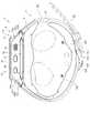
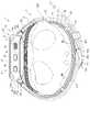
図1乃至図7に示すように、血圧測定装置1は、装置本体3と、手首に装置本体3を固定するベルト4と、ベルト4及び手首の間に配置されるカーラ5と、押圧カフ71、センシングカフ73及び引張カフ74を有するカフ構造体6と、装置本体3及びカフ構造体6を流体的に接続する流体回路7と、カーラ5に設けられた給電部8と、カーラ5及びカフ構造体6を覆うカバー(血圧測定装置用カフカバー)9と、を備えている。 As shown in FIGS. 1 to 7, the bloodpressure measuring device 1 includes a devicemain body 3, abelt 4 for fixing the devicemain body 3 to the wrist, acurler 5 arranged between thebelt 4 and the wrist, and apressure cuff 71. , acuff structure 6 having asensing cuff 73 and atension cuff 74, afluid circuit 7 fluidly connecting the devicemain body 3 and thecuff structure 6, apower supply portion 8 provided in thecurler 5, thecurler 5 and the cuff and a cover (blood pressure measuring device cuff cover) 9 that covers thestructure 6 .

図1乃至図7に示すように、装置本体3は、例えば、ケース11と、表示部12と、操作部13と、ポンプ14と、流路部15と、開閉弁16と、圧力センサ17と、電力供給部18と、振動モータ19と、制御基板20と、を備えている。装置本体3は、ポンプ14、開閉弁16、圧力センサ17及び制御基板20等によって、カフ構造体6に流体を供給する。 As shown in FIGS. 1 to 7, the devicemain body 3 includes, for example, acase 11, adisplay section 12, anoperation section 13, a pump 14, aflow path section 15, an on-offvalve 16, and apressure sensor 17. , apower supply unit 18 , avibration motor 19 , and acontrol board 20 . The apparatusmain body 3 supplies fluid to thecuff structure 6 using the pump 14, the on-offvalve 16, thepressure sensor 17, thecontrol board 20, and the like.

図1乃至図3に示すように、ケース11は、外郭ケース31と、外郭ケース31の手首200側とは反対側(外方側)の開口を覆う風防32と、外郭ケース31の内部の手首200側に設けられた基部33と、外郭ケース31の手首200側を覆う裏カバー35と、裏カバー35の下面に設けられるシール部材36と、を備えている。 As shown in FIGS. 1 to 3, thecase 11 includes anouter case 31, awindshield 32 covering an opening on the opposite side (outer side) of theouter case 31 from thewrist 200 side, and a wrist inside theouter case 31. A base 33 provided on the 200 side, aback cover 35 covering thewrist 200 side of theouter shell case 31, and aseal member 36 provided on the lower surface of theback cover 35 are provided.

外郭ケース31は、円筒状に形成される。外郭ケース31は、外周面の周方向で対称位置にそれぞれ設けられた一対のラグ31aと、2つの一対のラグ31a間にそれぞれ設けられるバネ棒31bと、を備えている。風防32は、例えば、円形状のガラス板である。Outer case 31 is formed in a cylindrical shape. Theouter case 31 includes a pair oflugs 31a provided at symmetrical positions on the outer peripheral surface in the circumferential direction, andspring bars 31b provided between the two pairs oflugs 31a. Thewindshield 32 is, for example, a circular glass plate.

基部33は、表示部12、操作部13、ポンプ14、開閉弁16、圧力センサ17、電力供給部18、振動モータ19及び制御基板20を保持する。また、基部33は、例えば、ポンプ14及びカフ構造体6を流体的に連続する流路部15の一部を構成する。 Thebase portion 33 holds thedisplay portion 12 , theoperation portion 13 , the pump 14 , the on-offvalve 16 , thepressure sensor 17 , thepower supply portion 18 , thevibration motor 19 and thecontrol board 20 . Also, thebase portion 33 constitutes part of thechannel portion 15 that fluidly connects the pump 14 and thecuff structure 6 , for example.

裏カバー35は、中央側が開口する環状に構成される。裏カバー35は、外郭ケース31の手首200側の端部の外周縁側を覆う。このような裏カバー35は、カーラ5と一体に組み合わされることで、中央の開口がカーラ5により覆われ、そしてカーラ5とともに外郭ケース31の手首200側の端部を覆う裏蓋を構成する。具体的には、裏カバー35は、4つの第1締結部材35aによってカーラ5に固定されるとともに、4つの第2締結部材35bによって外郭ケース31の手首200側の端部に固定される。裏カバー35は、底部に設けられ、カーラ5に固定される第1締結部材35aを挿通する4つの孔部35cと、外周部の4箇所が径方向に突出し、この突出した部位に設けられた外郭ケース31に固定される第2締結部材35bを挿通する4つの孔部35dと、を有する。 Theback cover 35 is configured in an annular shape with an open center side. Theback cover 35 covers the outer peripheral edge of the end of theouter case 31 on thewrist 200 side. Such aback cover 35 is integrally combined with thecurler 5 so that the central opening is covered with thecurler 5 and together with thecurler 5 constitutes a back cover that covers the end of theouter case 31 on thewrist 200 side. Specifically, theback cover 35 is fixed to thecurler 5 by fourfirst fastening members 35a, and is fixed to thewrist 200 side end of theouter case 31 by foursecond fastening members 35b. Therear cover 35 has fourholes 35c through which thefirst fastening members 35a fixed to thecurler 5 are inserted, and fourholes 35c protruding radially from the outer periphery. and fourholes 35d through which thesecond fastening members 35b fixed to theouter case 31 are inserted.

第1締結部材35a及び第2締結部材35bは、螺子、ボルト、ビス、リベット等の二つの部品を機械的に締結する部材である。本実施形態において、第1締結部材35a及び第2締結部材35bは、ネジである。 Thefirst fastening member 35a and thesecond fastening member 35b are members such as screws, bolts, screws, and rivets that mechanically fasten two parts. In this embodiment, thefirst fastening member 35a and thesecond fastening member 35b are screws.

シール部材36は、裏カバー35のカーラ5と接触する領域の形状に形成された、例えば両面テープである。シール部材36は、カーラ5及び裏カバー35の間に存することで、カーラ5及び裏カバー35間をシールする。 The sealingmember 36 is, for example, double-sided tape formed in the shape of the area of theback cover 35 that contacts thecurler 5 . Theseal member 36 is present between thecurler 5 and theback cover 35 to seal between thecurler 5 and theback cover 35 .

表示部12は、外郭ケース31の基部33上であって、且つ、風防32の直下に配置される。図7に示すように、表示部12は、電気的に制御基板20に接続される。表示部12は、例えば、液晶ディスプレイ又は有機エレクトロルミネッセンスディスプレイである。表示部12は、日時や最高血圧及び最低血圧などの血圧値や心拍数等の測定結果を含む各種情報を表示する。 Thedisplay unit 12 is arranged on thebase 33 of theouter case 31 and directly below thewindshield 32 . As shown in FIG. 7, thedisplay section 12 is electrically connected to thecontrol board 20 . Thedisplay unit 12 is, for example, a liquid crystal display or an organic electroluminescence display. Thedisplay unit 12 displays various information including date and time, blood pressure values such as systolic blood pressure and diastolic blood pressure, and measurement results such as heart rate.

操作部13は、使用者からの指令を入力可能に構成される。例えば、操作部13は、図1及び図7に示すように、ケース11に設けられた複数の釦41と、釦41の操作を検出するセンサ42と、表示部12又は風防32に設けられたタッチパネル43と、を備える。操作部13は、使用者が操作することで、指令を電気信号に変換する。センサ42及びタッチパネル43は、電気的に制御基板20に接続され、電気信号を制御基板20へ出力する。 Theoperation unit 13 is configured to be able to input commands from the user. For example, as shown in FIGS. 1 and 7, theoperation unit 13 includes a plurality ofbuttons 41 provided on thecase 11, asensor 42 for detecting the operation of thebuttons 41, and asensor 42 provided on thedisplay unit 12 orwindshield 32. Atouch panel 43 is provided. Theoperation unit 13 is operated by a user to convert commands into electrical signals. Thesensor 42 and thetouch panel 43 are electrically connected to thecontrol board 20 and output electrical signals to thecontrol board 20 .

複数の釦41は、例えば3つ設けられる。釦41は、基部33に支持されるとともに、外郭ケース31の外周面から突出する。複数の釦41及び複数のセンサ42は、基部33に支持される。タッチパネル43は、例えば、風防32に一体に設けられる。 For example, threebuttons 41 are provided. Thebutton 41 is supported by thebase portion 33 and protrudes from the outer peripheral surface of theouter shell case 31 . A plurality ofbuttons 41 and a plurality ofsensors 42 are supported bybase 33 . Thetouch panel 43 is provided integrally with thewindshield 32, for example.

ポンプ14は、例えば圧電ポンプである。ポンプ14は、空気を圧縮し、流路部15を介して圧縮空気をカフ構造体6に供給する。ポンプ14は、電気的に制御基板20に接続される。 Pump 14 is, for example, a piezoelectric pump. Pump 14 compresses air and supplies the compressed air tocuff structure 6 viaflow path 15 . Pump 14 is electrically connected to controlboard 20 .

流路部15は、図7に示すように、ポンプ14から押圧カフ71及び引張カフ74へつながる流路、及び、ポンプ14からセンシングカフ73へつながる流路を構成する。また、流路部15は、押圧カフ71及び引張カフ74から大気へつながる流路、及び、センシングカフ73から大気へつながる流路を構成する。流路部15は、基部33等に設けられた中空部、溝、流路タンク及びチューブ等により構成された空気の流路である。 As shown in FIG. 7 , thechannel portion 15 constitutes a channel connecting the pump 14 to thepressure cuff 71 and thetension cuff 74 and a channel connecting the pump 14 to thesensing cuff 73 . In addition, thechannel portion 15 constitutes a channel connecting thepressure cuff 71 and thetension cuff 74 to the atmosphere, and a channel connecting thesensing cuff 73 to the atmosphere. Theflow path portion 15 is an air flow path configured by a hollow portion, a groove, a flow path tank, a tube, and the like provided in thebase portion 33 and the like.

開閉弁16は、流路部15の一部を開閉する。開閉弁16は、複数、具体例として、図7に示すように、4つ設けられ、各開閉弁16の開閉の組み合わせによりポンプ14から押圧カフ71及び引張カフ74へつながる流路、ポンプ14からセンシングカフ73へつながる流路、押圧カフ71及び引張カフ74から大気へつながる流路、及び、センシングカフ73から大気へつながる流路を選択的に開閉する。具体例として、4つの開閉弁16は、第1開閉弁16A、第2開閉弁16B、第3開閉弁16C及び第4開閉弁16Dにより構成される。第1開閉弁16Aは、ポンプ14とセンシングカフ73とを接続する流路を開閉する。第2開閉弁16Bは、ポンプ14と引張カフ74とを接続する流路を開閉する。第2開閉弁16B及び第3開閉弁16Cは、ポンプ14と押圧カフ71とを接続する流路を開閉する。第2開閉弁16B、第3開閉弁16C及び第4開閉弁16Dは、ポンプ14及び大気を接続する流路を開閉する。 The on-offvalve 16 opens and closes a portion of theflow path portion 15 . A plurality of on-offvalves 16 are provided, as shown in FIG. 7, as a specific example, four are provided. The flow path leading to thesensing cuff 73, the flow path leading from thepressure cuff 71 and thetension cuff 74 to the atmosphere, and the flow path leading from thesensing cuff 73 to the atmosphere are selectively opened and closed. As a specific example, the four on-offvalves 16 are composed of a first on-offvalve 16A, a second on-offvalve 16B, a third on-offvalve 16C, and a fourth on-offvalve 16D. The first on-offvalve 16A opens and closes the flow path connecting the pump 14 and thesensing cuff 73 . The second on-offvalve 16B opens and closes the channel connecting the pump 14 and thetension cuff 74 . The second on-offvalve 16B and the third on-offvalve 16C open and close the flow path connecting the pump 14 and thepressure cuff 71 . The second on-offvalve 16B, the third on-offvalve 16C, and the fourth on-offvalve 16D open and close the flow path connecting the pump 14 and the atmosphere.

圧力センサ17は、少なくともセンシングカフ73の圧力を検出する。圧力センサ17は、例えば、第1圧力センサ17A及び第2圧力センサ17Bを備える。圧力センサ17は、検出した圧力を電気信号に変換し、制御基板20へ出力する。例えば、第1圧力センサ17A及び第2圧力センサ17Bは、流路部15の第1開閉弁16A及びセンシングカフ73を接続する流路に設けられる。この流路は押圧カフ71、センシングカフ73及び引張カフ74とポンプ14とが、各開閉弁の開閉によって連続することから、これら流路内の圧力がポンプ14のつながる押圧カフ71、センシングカフ73及び引張カフ74の内部空間の圧力となる。Thepressure sensor 17 detects at least the pressure of thesensing cuff 73 . Thepressure sensor 17 includes, for example, afirst pressure sensor 17A and asecond pressure sensor 17B. Thepressure sensor 17 converts the detected pressure into an electrical signal and outputs the electrical signal to thecontrol board 20 . For example, thefirst pressure sensor 17A and thesecond pressure sensor 17B are provided in a channel that connectsthe first on-offvalve 16A and thesensing cuff 73 of thechannel portion 15 . Since thepressure cuff 71, thesensing cuff 73, and thetension cuff 74 are connected to the pump 14 by opening and closing the opening/closing valves, the pressure in these channels changes to thepressure cuff 71 and thesensing cuff 73 to which the pump 14 is connected. and the pressure in the interior space oftensioning cuff 74 .

具体例として圧力センサ17は、第1開閉弁16Aが開であり、そして、第2開閉弁16B閉であるときにセンシングカフ73の圧力、換言すると、ポンプ14及びセンシングカフ73を接続する流路部15の圧力を検出する。また、圧力センサ17は、第1開閉弁16A及び第2開閉弁16Bが開であり、そして、第3開閉弁16Cが閉であるときに、センシングカフ73及び引張カフ74の圧力、換言すると、ポンプ14、センシングカフ73及び引張カフ74を接続する流路部15の圧力を検出する。さらに、圧力センサ17は、第1開閉弁16A、第2開閉弁16B及び第3開閉弁16Cが開であり、そして、第4開閉弁16Dが開又は閉であるときに、押圧カフ71、センシングカフ73及び引張カフ74の圧力、換言すると、ポンプ14、押圧カフ71、センシングカフ73及び引張カフ74を接続する流路部15の圧力を検出する。As a specific example, thepressure sensor 17 detects the pressure of thesensing cuff 73 when the first on-offvalve 16A is open and the second on-offvalve 16Bis closed. The pressure of thepassage portion 15 is detected. Further, thepressure sensor 17 detects the pressure of thesensing cuff 73 and thetension cuff 74, in other words, when the first on-offvalve 16A and the second on-offvalve 16B are open and the third on-offvalve 16C is closed. The pressure in thechannel portion 15 connecting the pump 14, thesensing cuff 73 and thetensioning cuff 74 is detected. Further, thepressure sensor 17 detects when the first on-offvalve 16A, the second on-offvalve 16B and the third on-offvalve 16C are open, and the fourth on-offvalve 16D is open or closed. The pressure of thecuff 73 and thetension cuff 74 , in other words, the pressure of thechannel portion 15 connecting the pump 14 , thepressure cuff 71 , thesensing cuff 73 and thetension cuff 74 is detected.

電力供給部18は、例えば、リチウムイオンバッテリ等の二次電池である。電力供給部18は、図7に示すように、制御基板20に電気的に接続される。電力供給部18は、制御基板20に電力を供給する。 Thepower supply unit 18 is, for example, a secondary battery such as a lithium ion battery. Thepower supply unit 18 is electrically connected to thecontrol board 20 as shown in FIG. Thepower supply unit 18 supplies power to thecontrol board 20 .

図7に示すように、制御基板20は、例えば、基板51と、加速度センサ52と、通信部53と、記憶部54と、制御部55と、を備えている。制御基板20は、加速度センサ52、通信部53、記憶部54及び制御部55が基板51に実装されることで構成される。 As shown in FIG. 7, thecontrol board 20 includes aboard 51, anacceleration sensor 52, acommunication section 53, a storage section 54, and acontrol section 55, for example. Thecontrol board 20 is configured by mounting theacceleration sensor 52 , thecommunication section 53 , the storage section 54 and thecontrol section 55 on theboard 51 .

基板51は、ケース11の基部33にビス等によって固定される。 Thesubstrate 51 is fixed to thebase portion 33 of thecase 11 with screws or the like.

加速度センサ52は、例えば、3軸加速度センサである。加速度センサ52は、装置本体3の互いに直交する3方向の加速度を表す加速度信号を制御部55に出力する。例えば、加速度センサ52は、検出された加速度から血圧測定装置1を装着した生体の活動量を測定するために用いられる。 Theacceleration sensor 52 is, for example, a triaxial acceleration sensor. Theacceleration sensor 52 outputs acceleration signals representing accelerations of the apparatusmain body 3 in three mutually orthogonal directions to thecontrol section 55 . For example, theacceleration sensor 52 is used to measure the amount of activity of the living body wearing the bloodpressure measurement device 1 from the detected acceleration.

通信部53は、外部の装置と無線又は有線によって情報を送受信可能に構成される。通信部53は、例えば、制御部55によって制御された情報や測定された血圧値及び脈拍等の情報を、ネットワークを介して外部の装置へ送信し、また、外部の装置からネットワークを介してソフトウェア更新用のプログラム等を受信して制御部に送る。 Thecommunication unit 53 is configured to be able to transmit and receive information to and from an external device wirelessly or by wire. Thecommunication unit 53 transmits, for example, information controlled by thecontrol unit 55 and information such as the measured blood pressure value and pulse rate to an external device via the network, and also transmits software from the external device via the network. It receives a program for updating and the like and sends it to the control unit.

本実施形態において、ネットワークは、例えばインターネットであるが、これに限定されず、病院内に設けられたLAN(Local Area Network)等のネットワークであってもよく、また、USB等の所定の規格の端子を有するケーブルなどを用いた外部の装置との直接的な通信であってもよい。このため、通信部53は、無線アンテナ及びマイクロUSBコネクタ等の複数を含む構成であってもよい。 In this embodiment, the network is, for example, the Internet, but is not limited to this, and may be a network such as a LAN (Local Area Network) provided in a hospital. Direct communication with an external device using a cable having a terminal may also be used. Therefore, thecommunication unit 53 may be configured to include a plurality of wireless antennas, micro USB connectors, and the like.

記憶部54は、血圧測定装置1全体及び流体回路7を制御するためのプログラムデータ、血圧測定装置1の各種機能を設定するための設定データ、圧力センサ17で測定された圧力から血圧値や脈拍を算出するための算出データ等を予め記憶する。また、記憶部54は、測定された血圧値や脈拍等の情報を記憶する。 The storage unit 54 stores program data for controlling the entire bloodpressure measuring device 1 and thefluid circuit 7 , setting data for setting various functions of the bloodpressure measuring device 1 , blood pressure values and pulse rate from the pressure measured by thepressure sensor 17 . Calculation data and the like for calculating is stored in advance. The storage unit 54 also stores information such as the measured blood pressure value and pulse rate.

制御部55は、単数又は複数のCPUにより構成され、血圧測定装置1全体の動作、及び、流体回路7の動作を制御する。制御部55は、表示部12、操作部13、ポンプ14、各開閉弁16及び各圧力センサ17に電気的に接続されるとともに、電力を供給する。また、制御部55は、操作部13及び圧力センサ17が出力する電気信号に基づいて、表示部12、ポンプ14及び開閉弁16の動作を制御する。 Thecontrol unit 55 is composed of one or more CPUs, and controls the operation of the entire bloodpressure measurement device 1 and the operation of thefluid circuit 7 . Thecontrol unit 55 is electrically connected to thedisplay unit 12, theoperation unit 13, the pump 14, the on-offvalves 16, and thepressure sensors 17, and supplies electric power. Thecontrol unit 55 also controls the operations of thedisplay unit 12 , the pump 14 and the on-offvalve 16 based on the electrical signals output by theoperation unit 13 and thepressure sensor 17 .

例えば、制御部55は、図7に示すように、血圧測定装置1全体の動作を制御するメインCPU(Central Processing Unit)56及び流体回路7の動作を制御するサブCPU57を有する。例えば、メインCPU56は、圧力センサ17が出力する電気信号から、最高血圧及び最低血圧などの血圧値や心拍数などの測定結果を求め、この測定結果に対応した画像信号を表示部12へ出力する。 For example, thecontrol section 55 has a main CPU (Central Processing Unit) 56 that controls the overall operation of the bloodpressure measurement device 1 and asub CPU 57 that controls the operation of thefluid circuit 7, as shown in FIG. For example, themain CPU 56 obtains blood pressure values such as systolic blood pressure and diastolic blood pressure, heart rate, and other measurement results from the electrical signal output by thepressure sensor 17, and outputs an image signal corresponding to the measurement results to thedisplay unit 12. .

例えば、サブCPU57は、操作部13から血圧を測定する指令が入力されると、ポンプ14及び開閉弁16を駆動して押圧カフ71及びセンシングカフ73に圧縮空気を送る。また、サブCPU57は、圧力センサ17が出力する電気信号に基づいて、ポンプ14の駆動及び停止、並びに、開閉弁16の開閉を制御する。サブCPU57は、ポンプ14及び開閉弁16を制御することで、圧縮空気を押圧カフ71及びセンシングカフ73に選択的に送るとともに、押圧カフ71及びセンシングカフ73を選択的に減圧する。 For example, when a command to measure blood pressure is input from theoperation unit 13 , thesub CPU 57 drives the pump 14 and the open/close valve 16 to send compressed air to thepressure cuff 71 andsensing cuff 73 . Thesub CPU 57 also controls the driving and stopping of the pump 14 and the opening and closing of the on-offvalve 16 based on the electrical signal output by thepressure sensor 17 . Thesub CPU 57 selectively sends compressed air to thepressure cuff 71 and thesensing cuff 73 and selectively decompresses thepressure cuff 71 and thesensing cuff 73 by controlling the pump 14 and the open/close valve 16 .

図1乃至図6に示すように、ベルト4は、一方の一対のラグ31a及びバネ棒31bに設けられた第1ベルト61と、他方の一対のラグ31a及びバネ棒31bに設けられた第2ベルト62と、を備える。ベルト4は、カーラ5を介して手首200に巻き付けられる。 As shown in FIGS. 1 to 6, thebelt 4 includes afirst belt 61 provided on one pair oflugs 31a andspring bar 31b and asecond belt 61 provided on the other pair oflugs 31a andspring bar 31b. abelt 62;Belt 4 is wrapped aroundwrist 200 viacurler 5 .

第1ベルト61は、所謂親と呼ばれ、第2ベルト62と連結可能な帯状に構成される。第1ベルト61は、図1乃至図3に示すように、ベルト部61a及び尾錠61bを有する。ベルト部61aは、帯状に構成される。ベルト部61aは、弾性変形可能な樹脂材料で形成される。また、ベルト部61aは、可撓性を有するとともに、ベルト部61aの長手方向の伸縮が抑制されるシート状のインサート部材を内部に有する。ベルト部61aは、一方の端部に形成され、ベルト部61aの長手方向に直交する第1孔部61c及び他方の端部に形成され、第1ベルト61の長手方向に直交する第2孔部61dを有する。 Thefirst belt 61 is called a so-called parent, and is configured in a belt shape connectable with thesecond belt 62 . Thefirst belt 61, as shown in FIGS. 1 to 3, has abelt portion 61a and abuckle 61b. Thebelt portion 61a is configured in a strip shape. Thebelt portion 61a is made of an elastically deformable resin material. Further, thebelt portion 61a has therein a sheet-like insert member that is flexible and suppresses expansion and contraction of thebelt portion 61a in the longitudinal direction. Thebelt portion 61a has afirst hole portion 61c formed at one end and perpendicular to the longitudinal direction of thebelt portion 61a, and a second hole portion formed at the other end portion and perpendicular to the longitudinal direction of thefirst belt 61. 61d.

図5、図6及び図8に示すように、第1孔部61cは、ベルト部61aの端部に設けられる。第1孔部61cは、バネ棒31bを挿入可能、且つ、バネ棒31bに関して第1ベルト61が回転可能な内径を有する。即ち、第1ベルト61は、一対のラグ31aの間であって、且つ、バネ棒31bに第1孔部61cが配置されることで、外郭ケース31に回転可能に保持される。 As shown in FIGS. 5, 6 and 8, thefirst hole 61c is provided at the end of thebelt portion 61a. Thefirst hole 61c has an inner diameter that allows insertion of thespring bar 31b and allows rotation of thefirst belt 61 with respect to thespring bar 31b. That is, thefirst belt 61 is rotatably held in theouter case 31 by arranging thefirst hole 61c in thespring bar 31b between the pair oflugs 31a.

図1及び図3に示すように、第2孔部61dは、ベルト部61aの先端に設けられる。第2孔部61dは、尾錠61bが取り付けられる。 As shown in FIGS. 1 and 3, thesecond hole portion 61d is provided at the tip of thebelt portion 61a. Abuckle 61b is attached to thesecond hole 61d.

図1及び図3に示すように、尾錠61bは、矩形枠状の枠状体61eと、枠状体61eに回転可能に取り付けられたつく棒61fと、を有する。枠状体61eは、つく棒61fが取り付けられた一辺が第2孔部61dに挿入され、ベルト部61aに関して回転可能に取り付けられる。 As shown in FIGS. 1 and 3, thebuckle 61b has a rectangular frame-shapedbody 61e and astick 61f rotatably attached to the frame-shapedbody 61e. The frame-like body 61e is rotatably attached to thebelt portion 61a by inserting one side of the frame-like body 61e to which thestick 61f is attached into thesecond hole portion 61d.

第2ベルト62は、所謂剣先と呼ばれ、枠状体61eに挿入可能な幅を有する帯状に構成される。第2ベルト62は、弾性変形可能な樹脂材料で形成される。また、第2ベルト62は、可撓性を有するとともに、第2ベルト62の長手方向の伸縮が抑制されるシート状のインサート部材を内部に有する。 Thesecond belt 62 is called a so-called tip, and is formed in a strip shape having a width that can be inserted into the frame-shapedbody 61e. Thesecond belt 62 is made of an elastically deformable resin material. In addition, thesecond belt 62 has therein a sheet-like insert member that is flexible and suppresses expansion and contraction of thesecond belt 62 in the longitudinal direction.

また、第2ベルト62は、図1及び図2に示すように、つく棒61fが挿入される小孔62aを複数有する。また、第2ベルト62は、一方の端部に設けられ、第2ベルト62の長手方向に直交する第3孔部62bを有する。第3孔部62bは、バネ棒31bを挿入可能、且つ、バネ棒31bに関して第2ベルト62が回転可能な内径を有する。即ち、第2ベルト62は、一対のラグ31aの間であって、且つ、バネ棒31bに第3孔部62bが配置されることで、外郭ケース31に回転可能に保持される。 1 and 2, thesecond belt 62 has a plurality ofsmall holes 62a into which sticks 61f are inserted. Thesecond belt 62 also has athird hole 62b provided at one end and perpendicular to the longitudinal direction of thesecond belt 62 . Thethird hole 62b has an inner diameter that allows insertion of thespring bar 31b and allows rotation of thesecond belt 62 with respect to thespring bar 31b. That is, thesecond belt 62 is rotatably held by theouter shell case 31 between the pair oflugs 31a and by arranging thethird holes 62b in the spring bars 31b.

このようなベルト4は、第2ベルト62が枠状体61eに挿入され、小孔62aにつく棒61fが挿入されることで、第1ベルト61及び第2ベルト62が一体に接続され、外郭ケース31とともに、手首200の周方向に倣った環状となる。ベルト4は、手首200の周方向に倣った環状となることで、カーラ5を押圧し、カーラ5を血圧測定装置1の装着者の手首の周方向に倣うように、弾性変形させる。 In such abelt 4, thefirst belt 61 and thesecond belt 62 are integrally connected by inserting thesecond belt 62 into the frame-shapedbody 61e and inserting therods 61f attached to thesmall holes 62a. Together with thecase 31, it forms an annular shape following the circumferential direction of thewrist 200. As shown in FIG. Thebelt 4 has a ring shape that follows the circumferential direction of thewrist 200 , presses thecurler 5 , and elastically deforms thecurler 5 so as to follow the circumferential direction of the wrist of the wearer of the bloodpressure measurement device 1 .

カーラ5は、図1乃至図3及び図6に示すように、手首200の周方向に倣って湾曲する帯状に構成される。カーラ5は、一端と他端が離間して形成される。カーラ5は、例えば、一端側の外面が装置本体3の裏カバー35に固定される。カーラ5は、一端及び他端が裏カバー35よりも手首200の一方の側方側に突出した位置に配置される。これにより、カーラ5は、血圧測定装置1を手首200に装着したときに、一端及び他端が手首200の側方に配置される。また、カーラ5は、所定の距離だけ離間して一端及び他端が隣接する。カーラ5は、例えば、樹脂材料で形成される。具体例として、カーラ5は、ポリプロピレンによって厚さが1mm程度に形成される。 As shown in FIGS. 1 to 3 and 6, thecurler 5 is configured in a band shape that curves along the circumferential direction of thewrist 200 . Thecurler 5 is formed with one end and the other end spaced apart. The outer surface of one end of thecurler 5 is fixed to theback cover 35 of the apparatusmain body 3, for example. Thecurler 5 is arranged at a position where one end and the other end protrude from theback cover 35 toward one side of thewrist 200 . Thereby, one end and the other end of thecurler 5 are arranged on the side of thewrist 200 when the bloodpressure measuring device 1 is worn on thewrist 200 . Also, thecurlers 5 are adjacent at one end and the other end with a predetermined distance therebetween. Thecurler 5 is made of, for example, a resin material. As a specific example, thecurler 5 is made of polypropylene and has a thickness of about 1 mm.

具体例として、図1乃至図3及び図6に示すように、カーラ5は、手首の周方向に倣って湾曲する帯状に構成される。また、カーラ5は、一端側の手首200の手の甲側に対向する位置に設けられ、裏カバー35とともに裏蓋を構成する円板状のカバー部5a、カバー部5aの周囲に設けられ、及び、外郭ケース31及び裏カバー35を固定する第2締結部材35bを移動可能な逃げ部5bを有する。カーラ5は、例えば、カバー部5a及びその隣接する部位が平板状に形成されるとともに、カバー部5aよりも一端側及び他端側が所定の曲率で湾曲して形成される。そして、カーラ5は、カバー部5aから一端までの長さが、カバー部5aから他端までの長さよりも短く形成される。具体例として、カーラ5は、カバー部5aから一端までの短手側が、手首の手の甲側に配置され、そして、カバー部5aから他端までの長手側が、手首の手の甲側から一方の側方を通って手首200の手の平側まで延びる。 As a specific example, as shown in FIGS. 1 to 3 and 6, thecurler 5 is configured in a belt shape that curves along the circumferential direction of the wrist. Further, thecurler 5 is provided at a position facing the back of the hand of thewrist 200 on the one end side, and is provided around a disk-shapedcover portion 5a forming a back cover together with theback cover 35, and around thecover portion 5a. It has anescape portion 5b that allows movement of thesecond fastening member 35b that fixes theouter shell case 31 and theback cover 35. As shown in FIG. Thecurler 5 is formed, for example, by forming thecover portion 5a and its adjacent portion in a flat plate shape, and curving one end side and the other end side of thecover portion 5a with a predetermined curvature. The length from thecover portion 5a to one end of thecurler 5 is shorter than the length from thecover portion 5a to the other end. As a specific example, the short side of thecurler 5 from thecover portion 5a to one end is arranged on the back side of the wrist, and the long side from thecover portion 5a to the other end is arranged on one side from the back side of the wrist. Extends through to the palm side of thewrist 200 .

また、図15に示すように、カーラ5は、一端及び他端が近接したときに、一端側の内周面側に他端が位置する形状に形成される。具体例として、カーラ5の手首200の幅方向の幅は、カーラ5の手首200の手の平側よりもカーラ5の手首200の手の甲側が大きく設定される。そして、カーラ5は、手首200の手の甲側の一端の曲率半径が手首200の手の平側の他端の曲率半径よりも大きく設定される。このような構成により、カーラ5は、カーラ5の両端側が当接すると、一端よりも他端がカーラ5の内方に配置される。また、カーラ5は、カバー部5aの一部、及び、カバー部5aから一端側の外面、さらに言えば、カバー部5aから延びる短手側の外面に、カバー部5aに隣接して設けられた窪み5cが設けられる。 Further, as shown in FIG. 15, thecurler 5 is formed in such a shape that the other end is located on the inner peripheral surface side of the one end side when the one end and the other end are close to each other. As a specific example, the width of thewrist 200 of thecurler 5 in the width direction is set larger on the back side of thewrist 200 of thecurler 5 than on the palm side of thewrist 200 of thecurler 5 . Thecurler 5 is set so that the radius of curvature of one end on the back side of thewrist 200 is larger than the radius of curvature of the other end on the palm side of thewrist 200 . With such a configuration, when both ends of thecurler 5 are brought into contact with each other, the other end of thecurler 5 is arranged inside thecurler 5 rather than the one end. Further, thecurler 5 is provided adjacent to thecover portion 5a on a part of thecover portion 5a and on the outer surface on the one end side from thecover portion 5a, more specifically on the outer surface on the short side extending from thecover portion 5a. Arecess 5c is provided.

カバー部5aは、インサートされた補強用のインサート部材5dを含む。カバー部5aは、固定された裏カバー35を介して外郭ケース31の手首200側に固定される。カバー部5aは、裏カバー35の4つの孔部35cと対向する位置に設けられ、裏カバー35を固定する第1締結部材35aが螺合される螺子孔5e、及び、カバー部5aは、カフ構造体6を装置本体3に接続するための3つ孔部5fを有する。 Thecover portion 5a includes an inserted reinforcinginsert member 5d. Thecover portion 5a is fixed to thewrist 200 side of theouter case 31 via the fixedback cover 35 . Thecover portion 5a is provided at a position facing the fourholes 35c of theback cover 35, and thescrew holes 5e into which thefirst fastening members 35a for fixing theback cover 35 are screwed, and thecover portion 5a includes a cuff. It has threeholes 5f for connecting thestructure 6 to the devicemain body 3. As shown in FIG.

逃げ部5bは、裏カバー35側から外郭ケース31に裏カバー35を第2締結部材35bにより固定するときに、第2締結部材35bがカーラ5に干渉せずに第2締結部材35bを裏カバー35に配置するため及び第2締結部材35bを回転させる工具を配置するための逃げである。 Theescape portion 5b prevents thesecond fastening member 35b from interfering with thecurler 5 when theback cover 35 is fixed to theouter case 31 from theback cover 35 side by the second fastening member 35b. 35 and for locating a tool for rotating thesecond fastening member 35b.

3つの孔部5fは、押圧カフ71の後述する接続部84を挿入可能な内径に形成された第1孔部5f1、センシングカフ73の後述する接続部93を挿入可能な内径に形成された第2孔部5f2、及び、引張カフ74の後述する接続部103を挿入可能な内径に形成された第3孔部5f3である。本実施形態において、第2孔部5f2は、第1孔部5f1及び第3孔部5f3よりも、カバー部5a内のカーラ5の手の平側の他端側に配置される。 The threeholes 5f are a first hole 5f1 formed with an inner diameter capable of inserting aconnection portion 84 described later of thepressure cuff 71, and a second hole 5f1 formed with an inner diameter capable of inserting aconnection portion 93 described later of thesensing cuff 73. They are the second hole portion 5f2 and the third hole portion 5f3 formed with an inner diameter capable of inserting the later-described connectingportion 103 of thetension cuff 74. As shown in FIG. In this embodiment, the second hole portion 5f2 is arranged closer to the other end of the palm side of thecurler 5 in thecover portion 5a than the first hole portion 5f1 and the third hole portion 5f3.

このようなカーラ5は、一端及び他端がベルト4の第2ベルト62と対向する向きで外郭ケース31に固定される。また、カーラ5は、少なくとも、手首200の手の平側と対向する位置が、手首200の手の平側に沿って周方向に沿って湾曲することで、手首200の手の平側と対向するカフ構造体6を、手首200の手の平側の形状に倣って湾曲させた状態で保持する。 Such acurler 5 is fixed to theouter case 31 with one end and the other end facing thesecond belt 62 of thebelt 4 . In addition, thecurler 5 has at least a position facing the palm side of thewrist 200 curved along the circumferential direction along the palm side of thewrist 200, thereby forming acuff structure 6 facing the palm side of thewrist 200. , and held in a curved state following the shape of the palm side of thewrist 200 .

また、カーラ5は、可撓性及び形状保持性を有する硬さを有する。ここで、可撓性とは、カーラ5にベルト4の外力が印加されたときに径方向に形状が変形することをいう。例えば、可撓性とは、ベルト4によってカーラ5が押圧されたときに、手首に近接するか、手首の形状に沿うか、又は、手首の形状に倣うように側面視の形状が変形することをいう。また、形状保持性とは、外力が印加されないときに、カーラ5が予め賦形された形状を維持できることをいう。例えば、形状保持性とは、本実施形態においてはカーラ5の形状が手首の周方向に沿って湾曲する形状を維持できることである。 In addition, thecurler 5 has a hardness with flexibility and shape retention. Here, flexibility means that thecurler 5 deforms in the radial direction when the external force of thebelt 4 is applied to thecurler 5 . For example, flexibility means that when thecurler 5 is pressed by thebelt 4, the shape in a side view is deformed so as to be close to the wrist, follow the shape of the wrist, or follow the shape of the wrist. Say. Further, the shape retainability means that thecurler 5 can maintain a preformed shape when no external force is applied. For example, shape retention means that the shape of thecurler 5 can maintain a curved shape along the circumferential direction of the wrist in this embodiment.

カーラ5は、内周面にカフ構造体6が配置され、そして、カーラ5の内周面形状に沿ってカフ構造体6を保持する。具体例として、カーラ5は、押圧カフ71及び引張カフ74が内周面に配置され、カーラ5並びに押圧カフ71及び引張カフ74との間に設けられる接合層75により、カフ構造体6が固定されることで、カフ構造体6を保持する。本実施形態においては、接合層75は、接着剤や両面テープである。 Thecurler 5 has acuff structure 6 arranged on its inner peripheral surface, and holds thecuff structure 6 along the shape of the inner peripheral surface of thecurler 5 . As a specific example, thecurler 5 has thepressure cuff 71 and thetension cuff 74 arranged on the inner peripheral surface, and thecuff structure 6 is fixed by thebonding layer 75 provided between thecurler 5 and thepressure cuff 71 and thetension cuff 74. By being held, thecuff structure 6 is held. In this embodiment, thebonding layer 75 is an adhesive or double-sided tape.

図2、図3、図16及び図17に示すように、カフ構造体6は、押圧カフ71と、背板72と、センシングカフ73と、引張カフ74と、を備えている。また、カフ構造体6は、各構成同士、及び、カーラ5とカフ71、74を接合する接合層75を備えている。カフ構造体6は、カーラ5に固定される。カフ構造体6は、押圧カフ71、背板72及びセンシングカフ73が積層してカーラ5に配置され、引張カフ74が押圧カフ71、背板72及びセンシングカフ73と離間してカーラ5に配置される。 As shown in FIGS. 2, 3, 16 and 17, thecuff structure 6 includes apressure cuff 71, aback plate 72, asensing cuff 73 and atension cuff 74. As shown in FIG. Thecuff structure 6 also includes abonding layer 75 that bonds the components together and thecurler 5 and thecuffs 71 and 74 . Acuff structure 6 is secured to thecurler 5 . In thecuff structure 6, thepressing cuff 71, theback plate 72 and thesensing cuff 73 are laminated and arranged on thecurler 5, and thetension cuff 74 is arranged on thecurler 5 apart from thepressing cuff 71, theback plate 72 and thesensing cuff 73. be done.

具体例として、カフ構造体6は、図6に示すように、カーラ5の手首200の手の平側の内周面に、カーラ5の内周面から手首200側に向かって、押圧カフ71、背板72及びセンシングカフ73の順に積層して固定される。また、カフ構造体6は、カーラ5の手首200の手の甲側の内周面に引張カフ74が配置される。カフ構造体6の各部材は、積層方向に隣接する部材に接合層75によって固定される。 As a specific example, as shown in FIG. 6, thecuff structure 6 is provided on the inner peripheral surface of thecurler 5 on the palm side of thewrist 200, from the inner peripheral surface of thecurler 5 toward thewrist 200 side. Theplate 72 and thesensing cuff 73 are stacked in order and fixed. In addition, thecuff structure 6 has atension cuff 74 arranged on the inner peripheral surface of thewrist 200 of thecurler 5 on the side of the back of the hand. Each member of thecuff structure 6 is fixed by abonding layer 75 to an adjacent member in the stacking direction.

押圧カフ71は、流路部15を介してポンプ14に流体的に接続される。押圧カフ71は、膨張することで背板72及びセンシングカフ73を手首200側に押圧する。押圧カフ71は、図11、図12、図16乃至図19に示すように、複数の、例えば二層の空気袋81と、カーラ5と対向する空気袋81に設けられた被接合部82と、空気袋81と連通する流路体83と、流路体83の先端に設けられた接続部84と、を含む。このような押圧カフ71は、複数のシート部材86を一体に溶着することで構成される。 Thepressure cuff 71 is fluidly connected to the pump 14 via thechannel portion 15 . Thepressing cuff 71 presses theback plate 72 and thesensing cuff 73 toward thewrist 200 by being inflated. As shown in FIGS. 11, 12, and 16 to 19, thepressure cuff 71 includes a plurality of, for example, two-layeredair bags 81 and ajoint portion 82 provided on theair bag 81 facing thecurler 5. , aflow path body 83 communicating with theair bag 81, and a connectingportion 84 provided at the tip of theflow path body 83. As shown in FIG. Such apressure cuff 71 is constructed by welding together a plurality ofsheet members 86 .

ここで、空気袋81とは、袋状構造体であり、本実施形態においては血圧測定装置1がポンプ14により空気を用いる構成であることから、空気袋を用いて説明するが、空気以外の流体を用いる場合には袋状構造体は、当該流体により膨張する流体袋であればよい。複数の空気袋81は、積層され、積層方向に流体的に連通する。 Here, theair bag 81 is a bag-like structure, and in the present embodiment, since the bloodpressure measurement device 1 is configured to use air by the pump 14, the description will be made using the air bag. When a fluid is used, the bag-like structure may be a fluid bag that expands with the fluid. A plurality ofair bags 81 are stacked and fluidly communicated in the stacking direction.

空気袋81は、一方向に長い矩形状の袋形状に形成される。また、空気袋81は、短手方向の幅が、カーラ5の短手方向の幅と同じ幅に設定される。空気袋81は、例えば、二枚のシート部材86を組み合わせ、図11、図12、図16乃至図19に示すように、溶着部81aを一方向に長い矩形枠状に熱により溶着することで構成される。また、二層の空気袋81は、二つの空気袋81を熱により溶着して一体に組み合わせるか、又は、隣り合う空気袋81の対向するシート部材86同士を溶着したあとに空気袋81を溶着して形成することで構成される。具体例として、二層の空気袋81は、互いに対向するシート部材86に設けられた開口によって流体的に連続する。また、二層の空気袋81は、対向するシート部材86同士を外周縁に位置する溶着部81aよりも小さい四辺枠状にブリッジ溶着し、このブリッジ溶着部(接合部)81bで複数の開口を囲うことで、隣り合う空気袋81を一体に形成し、そして、ブリッジ溶着部81bの内側で流体的に連続させる。Air bag 81 is formed in a rectangular bag shape elongated in one direction. The width of theair bag 81 in the lateral direction is set to be the same as the width of thecurler 5 in the lateral direction. 11, 12, and 16 to 19, theair bag 81 is formed by, for example, combining twosheet members 86 and heat-weldingthe weldedportions 81ainto a rectangular frame shape elongated in one direction . Configured. The two-layeredair bags 81 are formed by welding the twoair bags 81 together by heat, or by welding the facingsheet members 86 of theadjacent air bags 81 and then welding theair bags 81 together. It is constructed by forming As a specific example, the two layers ofair bladders 81 are fluidly connected by openings provided insheet members 86 facing each other. In addition, the two-layeredair bag 81 is formed by bridge-welding thesheet members 86 facing each other in a quadrilateral frame shape smaller than the weldedportion 81a located at the outer peripheral edge, and forming a plurality of openings at the bridge-welded portion (joint portion) 81b. By enclosing,adjacent air bladders 81 are integrally formed and fluidly connected inside thebridge weld 81b.

被接合部82は、カーラ5と隣接して配置される空気袋81の縁部の少なくとも一部に、単数又は複数設けられる。被接合部82は、空気袋81を構成するシート部材86の一部によって形成される。 One or a plurality of joinedportions 82 are provided on at least a portion of the edge portion of theair bag 81 arranged adjacent to thecurler 5 . The joinedportion 82 is formed by a portion of thesheet member 86 forming theair bag 81 .

本実施形態においては、被接合部82は、図11、図12、図16乃至図19示すように、空気袋81の短手方向の縁部のそれぞれに一つずつ設けられる例を用いて説明する。なお、例えば、被接合部82は、スリットにより空気袋81の長手方向に分割されていてもよく、また、空気袋81の長手方向に複数設けられていてもよい。被接合部82は、押圧カフ71がカーラ5の内周面に配置されたときに、少なくとも、カーラ5の外周面に接合される。また、例えば、二つの被接合部82は、積層され、そして溶着される。 In the present embodiment, as shown in FIGS. 11, 12, and 16 to 19, an example in which one joinedportion 82 is provided at each of the lateral edges of theair bag 81 will be described. do. For example, the joinedportion 82 may be divided in the longitudinal direction of theair bag 81 by slits, or may be provided in plurality in the longitudinal direction of theair bag 81 . The joinedportion 82 is joined to at least the outer peripheral surface of thecurler 5 when thepressure cuff 71 is arranged on the inner peripheral surface of thecurler 5 . Also, for example, the two parts to be joined 82 are stacked and welded.

なお、二つの被接合部82は、例えば、空気袋81の短手方向の長さが異なる長さに設定される。この例においては、二つの被接合部82は、カーラ5の短手方向の一端側において積層されて溶着される。なお、二つの被接合部82は、先端がカーラ5の外周面に配置可能であれば、その長さは適宜設定可能であり、積層可能であってもなくてもよいが、積層可能な長さに設定される場合には、先端がカーラ5の外周面の外縁よりも外方に延設されない長さが好ましい。 Note that the two joinedportions 82 are set to have different lengths in the lateral direction of theair bag 81, for example. In this example, the two to-be-joined parts 82 are laminated and welded on one end side of thecurler 5 in the short direction. The length of the two parts to be joined 82 can be appropriately set as long as the ends thereof can be arranged on the outer peripheral surface of thecurler 5, and may or may not be laminated. When it is set to a length, the length is preferably such that the tip does not extend outward from the outer edge of the outer peripheral surface of thecurler 5 .

流路体83は、図10、図16乃至図19に示すように、一つの空気袋81、例えば、カーラ5に隣接する空気袋81の長手方向の一方の縁部の一部に一体に設けられる。具体例として、流路体83は、空気袋81の装置本体3に近い端部に設けられる。また、流路体83は、空気袋81の短手方向の幅よりも小さい幅で一方向に長い形状に形成され、先端が円形状に形成される。流路体83は、先端に接続部84を有する。流路体83は、接続部84を介して流路部15に接続され、装置本体3の流路部15と空気袋81との間の流路を構成する。 As shown in FIGS. 10 and 16 to 19, thechannel body 83 is provided integrally with oneair bag 81, for example, a portion of one longitudinal edge of theair bag 81 adjacent to thecurler 5. be done. As a specific example, theflow path body 83 is provided at the end of theair bag 81 near the devicemain body 3 . Further, thechannel body 83 is formed in a shape elongated in one direction with a width smaller than the width in the lateral direction of theair bag 81, and has a circular tip. Theflow channel body 83 has a connectingportion 84 at its tip. Theflow channel body 83 is connected to theflow channel portion 15 via the connectingportion 84 and constitutes a flow channel between theflow channel portion 15 of the devicemain body 3 and theair bag 81 .

流路体83は、二枚のシート部材86に接続部84を配置した状態で、シート部材86の空気袋81を構成する領域に隣接するシート部材86の一部を一方向に長い枠状に熱により溶着することで構成される。このような流路体83は、カーラ5の内周面及び引張カフ74の間に配置され、先端がカーラ5のカバー部5aが設けられた領域の手首200側の主面であって、且つ、第1孔部5f1と対向する位置に配置される。また、流路体83の溶着部83aを除く幅は、例えば、3.8mmに形成される。 Theflow path body 83 is formed by forming a frame shape long in one direction on a portion of thesheet member 86 adjacent to the area forming theair bag 81 of thesheet member 86 in a state where the connectingportion 84 is arranged on the twosheet members 86 . It is constructed by welding with heat. Such achannel body 83 is arranged between the inner peripheral surface of thecurler 5 and thetension cuff 74, and the tip thereof is thewrist 200 side main surface of the region where thecover portion 5a of thecurler 5 is provided, and , is arranged at a position facing the first hole portion 5f1. Further, the width of thechannel body 83 excluding the weldedportion 83a is, for example, 3.8 mm.

なお、流路体83が設けられる空気袋81は、二枚のシート部材86を矩形枠状に溶着する溶着部81aの一部を非溶着とし、流路体83を構成する溶着部83aと連続する構成とすることで、空気袋81が流路体83に流体的に連続する。 In theair bag 81 in which theflow path body 83 is provided, a weldedportion 81a that welds twosheet members 86 in a rectangular frame shape is partly unwelded, and is continuous with the weldedportion 83a that constitutes theflow path body 83. By adopting such a configuration, theair bag 81 is fluidly connected to theflow channel body 83 .

接続部84は、例えばニップルである。接続部84は、流路体83の先端に設けられる。接続部84の先端は、流路体83を構成する二枚のシート部材86のうち、カーラ5と対向するシート部材86から露出する。接続部84は、カバー部5aの第1孔部5f1に挿通され、流路部15に接続される。 The connectingportion 84 is, for example, a nipple. The connectingportion 84 is provided at the tip of thechannel body 83 . The tip of the connectingportion 84 is exposed from thesheet member 86 facing thecurler 5 among the twosheet members 86 forming thechannel body 83 . Theconnection portion 84 is inserted through thefirst hole portion 5f 1 of thecover portion 5 a and connected to theflow path portion 15 .

具体例として、押圧カフ71は、図11、図12及び図32に示すように、手首200側から、第1シート部材86aと、第1シート部材86aと一層目の空気袋81を構成する第2シート部材86bと、第2シート部材86bと一体に接合されるとともに、被接合部82を構成する第3シート部材86cと、第3シート部材86cと二層目の空気袋81及び流路体83を構成する第4シート部材86dと、を備える。なお、押圧カフ71は、隣り合うシート部材86が熱による溶着により接合されることで一体に構成される。 As a specific example, as shown in FIGS. 11, 12 and 32, thepressure cuff 71 includes a first sheet member 86a, a first sheet member 86a, and a first sheet member 86a and a first sheet member 86a forming thefirst air bag 81 from thewrist 200 side. A second sheet member 86b, a third sheet member 86c integrally joined to the second sheet member 86b and forming the joinedportion 82, the third sheet member 86c, theair bag 81 of the second layer, and the channel body and a fourth sheet member 86d constituting 83. Thepressing cuff 71 is integrally formed by joiningadjacent sheet members 86 by heat welding.

第1シート部材86a及び第2シート部材86bは、空気袋81と同様の矩形状に構成され、四辺の周縁部が溶着されることで空気袋81を構成する。第2シート部材86b及び第3シート部材86cは、対向して配置され、それぞれ、二つの空気袋81を流体的に連続させる複数の開口86b1、86c1を有する。また、第2シート部材86b及び第3シート部材86cは、複数の開口86b1、86c1の周囲を、空気袋81を溶着した四辺よりも小さい四辺枠状に熱により溶着されることで、一体に接合される。 The first sheet member 86a and the second sheet member 86b are formed in the same rectangular shape as theair bag 81, and theair bag 81 is formed by welding peripheral edges on four sides thereof. The second sheet member 86b and the third sheet member 86c are arranged facing each other and have a plurality of openings 86b1 and 86c1 that fluidly connect the twoair bags 81, respectively. In addition, the second sheet member 86b and the third sheet member 86c are integrally joined together by heat-welding the periphery of the plurality of openings 86b1 and 86c1 in a frame shape with four sides smaller than the four sides to which theair bag 81 is welded. be done.

第3シート部材86cは、例えば、空気袋81、被接合部82及び流路体83を構成可能な形状に構成される。第4シート部材86dは、例えば、空気袋81及び流路体83を構成可能な形状に構成される。また、第4シート部材86dは、例えば、接続部84の先端を挿入可能な孔部86d1を有する。 The third sheet member 86c is configured in a shape capable of configuring theair bag 81, the joinedportion 82, and theflow path body 83, for example. The fourth sheet member 86d is configured in a shape capable of configuring theair bag 81 and theflow path body 83, for example. Further, the fourth sheet member 86d has, for example, a hole portion 86d1 into which the tip of the connectingportion 84 can be inserted.

第3シート部材86c及び第4シート部材86dは、対向して配置され、空気袋81及び流路体83が流体的に連続するように、空気袋81及び流路体83の周縁形状に沿って熱により溶着され、所定の形状に裁断されることで空気袋81、被接合部82及び流路体83を構成する。 The third sheet member 86c and the fourth sheet member 86d are arranged to face each other, along the peripheral shapes of theair bag 81 and theflow path body 83 so that theair bag 81 and theflow path body 83 are fluidly continuous. Theair bag 81 , the joinedportion 82 and theflow path body 83 are configured by being welded by heat and cut into a predetermined shape.

第4シート部材86dの孔部86d1に接続部84が配置され、孔部86d1の周囲が接続部84と熱により溶着される。さらに、第4シート部材86dはカーラ5の内周面に、第3シート部材86cの被接合部82はカーラ5の外周面に、それぞれ接合層75を介して接合される。 Theconnection portion 84 is arranged in the hole portion 86d1 of the fourth sheet member 86d, and the periphery of the hole portion 86d1 is welded to theconnection portion 84 by heat. Further, the fourth sheet member 86d is bonded to the inner peripheral surface of thecurler 5, and the bondedportion 82 of the third sheet member 86c is bonded to the outer peripheral surface of thecurler 5 via thebonding layer 75, respectively.

背板72は、図11、図12及び図32に示すように、接合層75により押圧カフ71の第1シート部材86aの外面に貼付される。背板72は、樹脂材料で板状に形成される。背板72は、例えば、ポリプロピレンからなり、厚さが1mm程度の板状に形成される。背板72は、形状追従性を有する。 Theback plate 72 is adhered to the outer surface of the first sheet member 86a of thepressure cuff 71 by abonding layer 75, as shown in FIGS. Theback plate 72 is formed in a plate shape from a resin material. Theback plate 72 is made of polypropylene, for example, and formed in a plate shape with a thickness of about 1 mm. Theback plate 72 has shape followability.

ここで、形状追従性とは、配置される手首200の被接触箇所の形状を倣うように背板72が変形可能な機能をいい、手首200の被接触箇所とは、背板72が対向する手首200の領域をいう。ここでの接触とは、直接的な接触及びセンシングカフ73を介した間接的な接触の双方を含む。 Here, the shape followability refers to the function that theback plate 72 can be deformed so as to follow the shape of the contacted portion of thewrist 200, and theback plate 72 faces the contacted portion of thewrist 200. Refers to the area of thewrist 200 . Contact here includes both direct contact and indirect contact viasensing cuff 73 .

例えば、図12に示すように、背板72は、両主面に長手方向に対して直交する方向に延びる複数の溝72aを有する。複数の溝72aは、背板72の厚さ方向においてそれぞれ対向する。また、複数の溝72aは、背板72の長手方向に等間隔に配置される。 For example, as shown in FIG. 12, theback plate 72 has a plurality ofgrooves 72a extending in directions orthogonal to the longitudinal direction on both main surfaces. The plurality ofgrooves 72 a face each other in the thickness direction of theback plate 72 . Further, the plurality ofgrooves 72a are arranged at equal intervals in the longitudinal direction of theback plate 72. As shown in FIG.

背板72は、複数の溝72aを有する部位が溝72aを有さない部位に比べて薄肉となることで、複数の溝72aを有する部位が変形しやすいことから、手首200の形状に倣って変形し、手首の周方向に延在する形状追従性を有する。背板72は、手首200の手の平側を覆う長さに形成される。背板72は、手首200の形状に沿った状態で、押圧カフ71からの押圧力をセンシングカフ73の背板72側の主面に伝達する。 Since the portion having the plurality ofgrooves 72a is thinner than the portion having nogrooves 72a, theback plate 72 can easily deform the portion having the plurality ofgrooves 72a. It deforms and has shape followability extending in the circumferential direction of the wrist. Theback plate 72 is formed with a length that covers the palm side of thewrist 200 . Theback plate 72 conforms to the shape of thewrist 200 and transmits the pressing force from thepressure cuff 71 to the main surface of thesensing cuff 73 on theback plate 72 side.

センシングカフ73は、流路部15を介してポンプ14に流体的に接続される。センシングカフ73は、背板72の手首200側の主面に固定される。センシングカフ73は、図6及び図32に示すように、手首200の動脈210が存する領域に直接接触する。ここで、動脈210とは、橈骨動脈及び尺骨動脈である。センシングカフ73は、背板72の長手方向及び幅方向で、背板72と同一形状か、又は、背板72よりも小さい形状に形成される。センシングカフ73は、膨張することで手首200の手の平側の動脈210が存する領域を圧迫する。センシングカフ73は、膨張した押圧カフ71により、背板72を介して手首200側に押圧される。Sensing cuff 73 is fluidly connected to pump 14 viachannel portion 15 . Thesensing cuff 73 is fixed to the main surface of theback plate 72 on thewrist 200 side.Sensing cuff 73 directly contacts the area ofwrist 200 whereartery 210 resides, as shown in FIGS. Here, thearteries 210 are the radial artery and the ulnar artery. Thesensing cuff 73 is formed to have the same shape as theback plate 72 or a shape smaller than theback plate 72 in the longitudinal direction and the width direction of theback plate 72 .Sensing cuff 73 presses the area whereartery 210 exists on the palm side ofwrist 200 by being inflated. Thesensing cuff 73 is pressed toward thewrist 200 through theback plate 72 by the inflatedpressing cuff 71 .

具体例として、センシングカフ73は、図11、図12、図16、図17、図20、図21に示すように、一つの空気袋91と、空気袋91と連通する流路体92と、流路体92の先端に設けられた接続部93と、を含む。センシングカフ73は、空気袋91の一方の主面が背板72に固定される。例えば、センシングカフ73は、背板72の手首200側の主面に接合層75により接合される。このようなセンシングカフ73は、二枚のシート部材96を一体に溶着することで構成される。 As a specific example, thesensing cuff 73 includes, as shown in FIGS. and a connectingportion 93 provided at the tip of theflow channel body 92 . Thesensing cuff 73 has one main surface of theair bag 91 fixed to theback plate 72 . For example, thesensing cuff 73 is bonded to the main surface of theback plate 72 on thewrist 200 side by thebonding layer 75 . Such asensing cuff 73 is constructed by welding two sheet members 96 together.

ここで、空気袋91とは、袋状構造体であり、本実施形態においては血圧測定装置1がポンプ14により空気を用いる構成であることから、空気袋を用いて説明するが、空気以外の流体を用いる場合には、袋状構造体は流体袋等であってもよい。Here, theair bag 91 is a bag-like structure, and in the present embodiment, since the bloodpressure measurement device 1 is configured to use air by the pump 14, the description will be made using the air bag. When using a fluid, the bag-like structure may be afluid bag or the like.

空気袋91は、一方向に長い矩形状に構成される。空気袋91は、例えば、一方向に長い二枚のシート部材96を組み合わせ、図11、図12、図16、図17、図20、図21に示すように、溶着部91aを一方向に長い矩形枠状に熱により溶着することで構成される。また、空気袋91は、例えば、空気袋91を背板72に接合層75を用いて接合するための面積を確保するために、接合代91bを有する。接合代91bは、例えば、背板72に対向するシート部材96により形成される。Air bag 91 is configured in a rectangular shape elongated in one direction. 11, 12, 16, 17, 20, and 21,theair bag 91 is formed by combining two sheets of sheet members 96 that are longin one direction . It is configured by heat welding in a rectangular frame shape. In addition, theair bag 91 has a joiningallowance 91b to secure an area for joining theair bag 91 to theback plate 72 using the joininglayer 75, for example. Thejoint allowance 91b is formed by a sheet member 96 facing theback plate 72, for example.

流路体92は、空気袋91の長手方向の一方の縁部の一部に一体に設けられる。具体例として、流路体92は、空気袋91の装置本体3に近い端部に設けられる。また、流路体92は、空気袋91の短手方向の幅よりも小さい幅で一方向に長い形状に形成され、先端が円形状に形成される。流路体92は、先端に接続部93を有する。流路体92は、接続部93を介して流路部15に接続され、装置本体3の流路部15と空気袋91との間の流路を構成する。Theflow path body 92 is provided integrally with a portion of one longitudinal edge of theair bag 91 . As a specific example, theflow path body 92 is provided at the end of theair bag 91 near the devicemain body 3 . Further, thechannel body 92 is formed in a shape elongated in one direction with a width smaller than the width of theair bag 91 in the lateral direction, and the end thereof is formed in a circular shape. Theflow channel body 92 has a connectingportion 93 at its tip. Theflow channel body 92 is connected to theflow channel portion 15 via theconnection portion 93 and constitutes a flow channel between theflow channel portion 15 of the devicemain body 3 and theair bag 91 .

流路体92は、二枚のシート部材96に接続部93を配置した状態で、シート部材96の空気袋91を構成する領域に隣接するシート部材96の一部を一方向に長い枠状に熱により溶着することで構成される。なお、空気袋91は、二枚のシート部材96を矩形枠状に溶着する溶着部91aの一部を非溶着とし、流路体92を構成する溶着部92aと連続する構成とすることで、空気袋91及び流路体92を流体的に連続する。このような流路体92は、カーラ5の内周面及び引張カフ74の間に配置され、先端がカーラ5のカバー部5aが設けられた領域の手首200側の主面であって、且つ、第2孔部5f2と対向する位置に配置される。また、流路体92の溶着部92aを除く幅は、例えば、3.8mmに形成される。 Theflow path body 92 is formed by forming a frame-like portion of the sheet member 96 adjacent to the area forming theair bag 91 of the sheet member 96 in a state in which the connectingportion 93 is arranged on the two sheet members 96 . It is constructed by welding with heat. In theair bag 91, a weldedportion 91a where two sheet members 96 are welded together in a rectangular frame shape is partly unwelded, and is continuous with the weldedportion 92a forming theflow path body 92. Theair bag 91 and thechannel body 92 are fluidly connected. Such aflow path body 92 is arranged between the inner peripheral surface of thecurler 5 and thetension cuff 74, and the tip thereof is thewrist 200 side main surface of the area where thecover portion 5a of thecurler 5 is provided, and , is arranged at a position facing the second hole portion 5f2. Further, the width of thechannel body 92 excluding the weldedportion 92a is, for example, 3.8 mm.

接続部93は、例えばニップルである。接続部93は、流路体92の先端に設けられる。また、接続部93の先端は、流路体92を構成する二枚のシート部材96のうち、カーラ5及び背板72と対向するシート部材96から外部に露出する。接続部93は、カバー部5aの第2孔部5f2に挿通され、流路部15に接続される。 The connectingportion 93 is, for example, a nipple. The connectingportion 93 is provided at the tip of theflow path body 92 . Further, the tip of theconnection portion 93 is exposed to the outside from the sheet member 96 facing thecurler 5 and theback plate 72 among the two sheet members 96 forming theflow path body 92 . Theconnection portion 93 is inserted through thesecond hole portion 5 f 2 of thecover portion 5 a and connected to theflow path portion 15 .

具体例として、センシングカフ73は、図11及び図12に示すように、手首200側から第5シート部材96a及び第6シート部材96bを備える。なお、センシングカフ73は、隣り合うシート部材96が熱による溶着により接合されることで構成される。 As a specific example, thesensing cuff 73 includes a fifth sheet member 96a and a sixth sheet member 96b from thewrist 200 side, as shown in FIGS. Thesensing cuff 73 is configured by joining adjacent sheet members 96 by heat welding.

例えば、第5シート部材96a及び第6シート部材96bは、空気袋91、接合代91b及び流路体92を構成可能な形状に構成される。第5シート部材96a及び第6シート部材96bは対向して配置され、空気袋91及び流路体92が流体的に連続するように、空気袋91及び流路体92の周縁形状に沿って熱により溶着され、所定の形状に裁断されることで空気袋91及び流路体92が構成される。 For example, the fifth sheet member 96a and the sixth sheet member 96b are configured to have a shape capable of configuring theair bag 91, the joiningmargin 91b, and theflow path body 92. As shown in FIG. The fifth sheet member 96a and the sixth sheet member 96b are arranged to face each other, and heat is applied along the peripheral shapes of theair bag 91 and theflow path body 92 so that theair bag 91 and theflow path body 92 are fluidly continuous. Theair bag 91 and theflow path body 92 are formed by being welded and cut into a predetermined shape.

また、第6シート部材96bは、例えば、接続部93の先端を挿入可能な孔部96b1を有する。孔部96b1に接続部93が配置され、孔部96b1の周囲が接続部93と熱により溶着される。第6シート部材96bは、背板72の内周面に、接合層75を介して接合される。 Further, the sixth sheet member 96b has, for example, a hole portion 96b1 into which the tip of theconnection portion 93 can be inserted. Theconnection portion 93 is arranged in the hole portion 96b1, and the periphery of the hole portion 96b1 is welded to theconnection portion 93 by heat. The sixth sheet member 96b is bonded to the inner peripheral surface of theback plate 72 with thebonding layer 75 interposed therebetween.

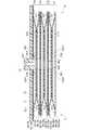
引張カフ74は、流路部15を介してポンプ14に流体的に接続される。引張カフ74は、膨張することで手首200から離間するようにカーラ5を押圧することで、ベルト4及びカーラ5を手首200の手の甲側に引っ張る。引張カフ74は、複数の、例えば六層の空気袋101と、カーラ5と対向する空気袋101に設けられた被接合部102と、カーラ5と対向する空気袋101に設けられた接続部103と、少なくともカーラ5と対向する空気袋101に設けられた切欠部104と、を含む。このような引張カフ74は、複数のシート部材106を一体に溶着することで構成される。また、引張カフ74は、流路体83、92が設けられた領域、及び、カバー部5aを含むカーラ5の手首200の手の甲側に固定される。即ち、カーラ5の手首200の手の甲側及び引張カフ74の間に、押圧カフ71の流路体83及びセンシングカフ73の流路体92が配置される。Tension cuff 74 is fluidly connected to pump 14 viaflow path 15 . Thetension cuff 74 pulls thebelt 4 and thecurler 5 toward the back of thewrist 200 by pushing thecurler 5 away from thewrist 200 when inflated. Thetension cuff 74 includes a plurality of, for example, six layers ofair bags 101 , ajoint portion 102 provided on theair bag 101 facing thecurler 5 , and a connectingportion 103 provided on theair bag 101 facing thecurler 5 . and anotch 104 provided in theair bag 101 facing at least thecurler 5 . Such atension cuff 74 is constructed by welding a plurality of sheet members 106 together. Further, thetension cuff 74 is fixed to the back of the hand side of thewrist 200 of thecurler 5 including the region where thechannel bodies 83 and 92 are provided and thecover portion 5a. That is, thechannel body 83 of thepressure cuff 71 and thechannel body 92 of thesensing cuff 73 are arranged between the back side of thewrist 200 of thecurler 5 and thetension cuff 74 .

また、引張カフ74は、膨張方向、本実施形態においては、カーラ5及び手首200の対向する方向で、膨張時の厚さが、押圧カフ71の膨張方向における膨張時の厚さ、及び、センシングカフ73の膨張方向における膨張時の厚さよりも厚く構成される。即ち、引張カフ74の空気袋101は、押圧カフ71の空気袋81及びセンシングカフ73の空気袋91よりも多い層構造を有し、カーラ5から手首200に向かって膨張したときの厚さが押圧カフ71及びセンシングカフ73よりも厚い。 In addition, thetension cuff 74 has a thickness when inflated in the inflating direction, which is the direction in which thecurler 5 and thewrist 200 face each other in this embodiment, a thickness when inflating in the inflating direction of thepressure cuff 71, and a sensing It is configured to be thicker than the thickness of thecuff 73 when inflated in the inflating direction. That is, theair bag 101 of thetension cuff 74 has a more layered structure than theair bag 81 of thepressure cuff 71 and theair bag 91 of thesensing cuff 73, and the thickness when inflated from thecurler 5 toward thewrist 200 is Thicker than thepressure cuff 71 and thesensing cuff 73 .

本実施形態において、六層の空気袋101を含む引張カフ74は、一つの空気袋101により構成される第1外層111、第1外層111に熱により溶着して一体に組み合わされた二層の空気袋101により構成される第1中間層112、第1中間層112に熱により溶着して一体に組み合わされた二層の空気袋101により構成される第2中間層113、及び、第2中間層113に熱により溶着して一体に組み合わされた一つの空気袋101により構成される第2外層114を備える。 In this embodiment, thetension cuff 74 including six layers ofair bladders 101 is composed of a firstouter layer 111 composed of oneair bladder 101 and two layers integrally combined by being thermally welded to the firstouter layer 111. A firstintermediate layer 112 made up ofair bags 101, a secondintermediate layer 113 made up of two layers ofair bags 101 integrally combined by being thermally welded to the firstintermediate layer 112, and a second intermediate. A secondouter layer 114 is provided which is composed of oneair bladder 101 thermally welded to thelayer 113 and combined together.

ここで、空気袋101とは、袋状構造体であり、本実施形態においては血圧測定装置1がポンプ14により空気を用いる構成であることから、空気袋を用いて説明するが、空気以外の流体を用いる場合には、袋状構造体は当該流体により膨張する流体袋であればよい。複数の空気袋101は、積層され、積層方向に流体的に連通する。 Here, theair bag 101 is a bag-like structure, and in the present embodiment, since the bloodpressure measurement device 1 is configured to use air by the pump 14, the description will be made using the air bag. When a fluid is used, the bag-like structure may be a fluid bag that expands with the fluid. A plurality ofair bags 101 are stacked and fluidly communicated in the stacking direction.

空気袋101は、一方向に長い矩形状の袋形状に形成される。また、空気袋101は、短手方向の幅が、カーラ5の短手方向の幅と同じ幅に設定される。空気袋101は、例えば、二枚のシート部材106を組み合わせ、図13、図14、図16及び図17に示すように、溶着部101aを一方向に長い矩形枠状に熱により溶着することで構成される。六層の空気袋101は、互いに対向するシート部材106に設けられた開口によって流体的に連続する。Air bag 101 is formed in a rectangular bag shape elongated in one direction. The width of theair bag 101 in the lateral direction is set to be the same as the width of thecurler 5 in the lateral direction. Theair bag 101 is formed by, for example, combining two sheet members 106 and heat-welding thewelding portion 101ainto a rectangular frame shape elongated in one directionas shown in FIGS. Configured. Six layers ofair bags 101 are fluidly connected by openings provided in sheet members 106 facing each other.

また、六層の空気袋101は、第1外層111及び第1中間層112、第1中間層112及び第2中間層113、並びに、第2中間層113及び第2外層114がそれぞれ対向するシート部材106同士を外周縁に位置する溶着部81aよりも小さい四辺枠状にブリッジ溶着し、このブリッジ溶着部(接合部)101bで複数の開口を囲うことで、隣り合う空気袋101を一体に形成し、そして、ブリッジ溶着部101bの内側で流体的に連続させる。In addition, the six-layeredair bag 101 is a sheet in which the firstouter layer 111 and the firstintermediate layer 112, the firstintermediate layer 112 and the secondintermediate layer 113, and the secondintermediate layer 113 and the secondouter layer 114 face each other. The members 106 are bridge-welded to each other in a quadrilateral frame shape smaller than the weldedportion 81a located on the outer periphery, and theadjacent air bags 101 are integrally formed by surrounding a plurality of openings with the bridge-welded portion (joint portion) 101b. and fluidly continuous inside thebridge weld 101b.

第1外層111は、手首200側に配置される一つの空気袋101により形成される。第1外層111は、六層の空気袋101のうち、手首200側から第一層の空気袋101を構成する。 The firstouter layer 111 is formed by oneair bag 101 arranged on thewrist 200 side. The firstouter layer 111 constitutes the firstlayer air bag 101 from thewrist 200 side of the sixlayers air bag 101 .

第1中間層112は、第1外層111に積層される。第1中間層112は、二層の空気袋101により形成される。第1中間層112は、六層の空気袋101のうち、手首200側から第二層及び第三層の空気袋101を構成する。第1中間層112は、二層の空気袋101が外周縁で一体に溶着されることで構成される。換言すると、第1中間層112は、4枚のシート部材106を空気袋101の外周縁形状で一体に溶着することで形成される。 The firstintermediate layer 112 is laminated on the firstouter layer 111 . The firstintermediate layer 112 is formed by two layers ofair bladders 101 . The firstintermediate layer 112 constitutes the second and third layers of theair bladder 101 from thewrist 200 side of the six layers of theair bladder 101 . The firstintermediate layer 112 is configured by welding the two layers of theair bag 101 together at their outer peripheral edges. In other words, the firstintermediate layer 112 is formed by integrally welding the four sheet members 106 in the shape of the outer periphery of theair bag 101 .

第2中間層113は、第1中間層112に積層される。第2中間層113は、二層の空気袋101により形成される。第2中間層113は、六層の空気袋101のうち、手首200側から第四層及び第五層の空気袋101を構成する。第2中間層113は、二層の空気袋101が外周縁で一体に溶着されることで構成される。換言すると、第2中間層113は、4枚のシート部材106を空気袋101の外周縁形状で一体に溶着することで形成される。 The secondintermediate layer 113 is laminated on the firstintermediate layer 112 . The secondintermediate layer 113 is formed by two layers ofair bladder 101 . The secondintermediate layer 113 constitutes the fourth andfifth air bladders 101 from thewrist 200 side of the sixair bladders 101 . The secondintermediate layer 113 is configured by welding the two layers of theair bag 101 together at their outer peripheral edges. In other words, the secondintermediate layer 113 is formed by integrally welding the four sheet members 106 in the shape of the outer periphery of theair bag 101 .

第2外層114は、カーラ5側に配置される一つの空気袋101により形成される。第2外層114は、六層の空気袋101のうち、手首200側から第六層の空気袋101を構成する。 The secondouter layer 114 is formed by oneair bladder 101 arranged on thecurler 5 side. The secondouter layer 114 constitutes thesixth air bladder 101 from thewrist 200 side of the sixair bladders 101 .

被接合部102は、カーラ5と隣接して配置される空気袋(第六層の空気袋)101の縁部の少なくとも一部に、単数又は複数設けられる。被接合部102は、空気袋101を構成するシート部材106の一部によって形成される。 One or a plurality of joinedportions 102 are provided on at least part of the edge of the air bag (sixth layer air bag) 101 arranged adjacent to thecurler 5 . Joinedportion 102 is formed by a portion of sheet member 106 formingair bag 101 .

本実施形態においては、被接合部102は、空気袋101の短手方向の縁部のそれぞれに、空気袋101の長手方向で二つずつ設けられる例を用いて説明する。なお、例えば、被接合部102は、カーラ5のカバー部5aと対向する位置を避けて空気袋101に設けられる。また、例えば、被接合部102は、カーラ5に設けられた給電部8の後述する給電端子8bと対向する部位に、給電端子8bを外部に露出させるための逃げ部102aを有する。逃げ部102aは、例えば、給電端子8bを外部に露出可能な開口であり、一例として円形状である。 In the present embodiment, an example in which two joinedportions 102 are provided in the longitudinal direction of theair bag 101 at each edge portion in the short direction of theair bag 101 will be described. In addition, for example, the joinedportion 102 is provided in theair bag 101 so as to avoid a position facing thecover portion 5 a of thecurler 5 . In addition, for example, the joinedportion 102 has anescape portion 102a for exposing thepower supply terminal 8b to the outside at a portion of thepower supply portion 8 provided in thecurler 5 that faces thepower supply terminal 8b, which will be described later. Therelief portion 102a is, for example, an opening through which thepower supply terminal 8b can be exposed to the outside, and has a circular shape as an example.

被接合部102は、引張カフ74がカーラ5の内周面に配置されたときに、少なくとも、カーラ5の外周面に接合される。また、空気袋101の短手方向で同じ位置に配置される被接合部102は、積層され、そして溶着される。 The joinedportion 102 is joined to at least the outer peripheral surface of thecurler 5 when thetension cuff 74 is arranged on the inner peripheral surface of thecurler 5 . Also, the parts to be joined 102 arranged at the same position in the lateral direction of theair bag 101 are stacked and welded.

なお、二つの被接合部102は、例えば、空気袋101の短手方向の長さが異なる長さに設定される。この例においては、二つの被接合部102は、カーラ5の短手方向の一端側において積層されて溶着される。なお、二つの被接合部102は、先端がカーラ5の外周面に配置可能であれば、その長さは適宜設定可能であり、積層可能であってもなくてもよいが、積層可能な長さに設定される場合には、先端がカーラ5の外周面の外縁よりも外方に延設されない長さが好ましい。 Note that the two joinedportions 102 are set to have different lengths in the short direction of theair bag 101, for example. In this example, the two parts to be joined 102 are laminated and welded on one end side of thecurler 5 in the short direction. The length of the two parts to be joined 102 can be appropriately set as long as the ends thereof can be arranged on the outer peripheral surface of thecurler 5, and may or may not be laminated. When it is set to a length, the length is preferably such that the tip does not extend outward from the outer edge of the outer peripheral surface of thecurler 5 .

接続部103は、例えばニップルである。接続部103は、カーラ5と隣接して配置される空気袋101の長手方向で中央側であって、且つ、カバー部5aの第3孔部5f3と対向する位置に設けられる。接続部103の先端は、空気袋101を構成する二枚のシート部材106のうち、カーラ5と対向するシート部材106から露出する。接続部103は、カバー部5aの第3孔部5f3に挿通され、流路部15に接続される。 The connectingportion 103 is, for example, a nipple. The connectingportion 103 is provided on the central side in the longitudinal direction of theair bag 101 arranged adjacent to thecurler 5 and at a position facing the third hole portion 5f3 of thecover portion 5a. The tip of the connectingportion 103 is exposed from the sheet member 106 facing thecurler 5 among the two sheet members 106 forming theair bag 101 . Theconnection portion 103 is inserted through thethird hole portion 5f 3 of thecover portion 5 a and connected to theflow path portion 15 .

切欠部104は、カーラ5に設けられた逃げ部5bと対向する位置に設けられる。切欠部104は、第2外層114を形成する第六層の空気袋101に設けられる。 Thenotch portion 104 is provided at a position facing therelief portion 5 b provided on thecurler 5 . Thenotch 104 is provided in the sixthlayer air bag 101 forming the secondouter layer 114 .

具体例として、引張カフ74は、図13及び図14に示すように、手首200側から、第7シート部材106aと、第8シート部材106bと、第9シート部材106cと、第10シート部材106dと、第11シート部材106eと、第12シート部材106fと、第13シート部材106gと、第14シート部材106hと、第15シート部材106iと、第16シート部材106jと、第17シート部材106kと、第18シート部材106lと、を備えている。なお、引張カフ74は、隣り合うシート部材106が熱による溶着により接合されることで一体に構成される。 As a specific example, as shown in FIGS. 13 and 14, thetension cuff 74 includes a seventh sheet member 106a, an eighth sheet member 106b, a ninth sheet member 106c, and a tenth sheet member 106d from thewrist 200 side. , the 11th sheet member 106e, the 12th sheet member 106f, the 13th sheet member 106g, the 14th sheet member 106h, the 15th sheet member 106i, the 16th sheet member 106j, and the 17th sheet member 106k. , and an eighteenth sheet member 106l. Thetension cuff 74 is integrally formed by joining adjacent sheet members 106 by heat welding.

第7シート部材106a乃至第18シート部材106lは、空気袋101と同様の矩形状に構成される。第7シート部材106a及び第8シート部材106bは、空気袋101の四辺の周縁部形状に沿って熱により溶着されることで、手首200側から一層目(第一層)の空気袋101を構成する。即ち、第7シート部材106a及び第8シート部材106bは、第1外層111を構成する。 The seventh sheet member 106 a to the eighteenth sheet member 106 l are configured in the same rectangular shape as theair bag 101 . The seventh sheet member 106a and the eighth sheet member 106b are thermally welded along the four sides of theair bag 101 to form the first layer (first layer) of theair bag 101 from thewrist 200 side. do. That is, the seventh sheet member 106 a and the eighth sheet member 106 b constitute the firstouter layer 111 .

第8シート部材106b及び第9シート部材106cは、対向して配置され、それぞれ、二つの空気袋101を流体的に連続させる複数の開口106b1、106c1を有する。また、第8シート部材106b及び第9シート部材106cは、複数の開口106b1、106c1の周囲を、空気袋101を溶着した四辺よりも小さい四辺枠状に熱によりブリッジ溶着されることで、一体に接合される。 The eighth sheet member 106b and the ninth sheet member 106c are arranged facing each other and have a plurality of openings 106b1 and 106c1 that fluidly connect the twoair bladders 101, respectively. In addition, the eighth sheet member 106b and the ninth sheet member 106c are integrally welded together by thermally bridge-welding the periphery of the plurality of openings 106b1 and 106c1 into a four-sided frame shape smaller than the four sides to which theair bag 101 is welded. spliced.

第9シート部材106c及び第10シート部材106dは、空気袋101の四辺の周縁部形状に沿って熱により溶着されることで、手首200側から二層目(第二層)の空気袋101を構成する。 The ninth sheet member 106c and the tenth sheet member 106d are thermally welded along the four sides of theair bag 101 to form the second layer (second layer) of theair bag 101 from thewrist 200 side. Configure.

第10シート部材106d及び第11シート部材106eは、図13及び図14に示すように、対向して配置され、それぞれ、二つの空気袋101を流体的に連続させる複数の開口106d1、106e1を有する。第11シート部材106e及び第12シート部材106fは、空気袋101の四辺の周縁部形状に沿って熱により溶着されることで、手首200側から三層目(第三層)の空気袋101を構成する。 The tenth sheet member 106d and the eleventh sheet member 106e are arranged facing each other, as shown in FIGS. . The eleventh sheet member 106e and the twelfth sheet member 106f are thermally welded along the four sides of theair bag 101 to form the third layer (third layer) of theair bag 101 from thewrist 200 side. Configure.

なお、第9シート部材106、第10シート部材106d、第11シート部材106e及び第12シート部材106fは、空気袋101の四辺の周縁部形状に沿って熱により一体に溶着されることで、第二層及び第三層の空気袋101が一体に形成された第1中間層112を構成する。The ninth sheet member 106c, the tenth sheet member 106d, the eleventh sheet member106e , and the twelfth sheet member 106f are integrallywelded together by heat along the shape of the four sides of theair bag 101. , the second layer and the third layer ofair bladders 101 constitute a firstintermediate layer 112 integrally formed.

第12シート部材106f及び第13シート部材106gは、図13及び図14に示すように、対向して配置され、それぞれ、二つの空気袋101を流体的に連続させる複数の開口106f1、106g1を有する。また、第12シート部材106f及び第13シート部材106gは、複数の開口106f1、106g1の周囲を、空気袋101を溶着した四辺よりも小さい四辺枠状に熱によりブリッジ溶着されることで、一体に接合される。 The twelfth sheet member 106f and the thirteenth sheet member 106g are arranged facing each other, as shown in FIGS. . In addition, the twelfth sheet member 106f and the thirteenth sheet member 106g are bridge-welded around the plurality of openings 106f1 and 106g1 by heat in a four-sided frame shape smaller than the four sides to which theair bag 101 is welded. spliced.

第13シート部材106g及び第14シート部材106hは、空気袋101の四辺の周縁部形状に沿って熱により溶着されることで、手首200側から四層目(第四層)の空気袋101を構成する。 The thirteenth sheet member 106g and the fourteenth sheet member 106h are thermally welded along the four-sided peripheral edge portions of theair bag 101, thereby forming the fourth layer (fourth layer) of theair bag 101 from thewrist 200 side. Configure.

第14シート部材106h及び第15シート部材106iは、図13及び図14に示すように、対向して配置され、それぞれ、二つの空気袋101を流体的に連続させる複数の開口106h1、106i1を有する。第15シート部材106i及び第16シート部材106jは、空気袋101の四辺の周縁部形状に沿って熱により溶着されることで、手首200側から五層目(第五層)の空気袋101を構成する。 The fourteenth sheet member 106h and the fifteenth sheet member 106i are arranged facing each other as shown in FIGS. . The fifteenth sheet member 106i and the sixteenth sheet member 106j are welded by heat along the shape of the four sides of theair bag 101, thereby forming the fifth layer (fifth layer) of theair bag 101 from thewrist 200 side. Configure.

なお、第13シート部材106、第14シート部材106、第15シート部材106i及び第16シート部材106は、空気袋101の四辺の周縁部形状に沿って熱により一体に溶着されることで、第四層及び第五層の空気袋101が一体に形成された第2中間層113を構成する。The thirteenth sheet member 106g , the fourteenth sheet member 106h , the fifteenth sheet member 106i and the sixteenth sheet member 106j are welded integrally by heat along the four peripheral edges of theair bag 101 . Thus, a secondintermediate layer 113 in which theair bladders 101 of the fourth layer and the fifth layer are integrally formed is configured.

第16シート部材106j及び第17シート部材106kは、図13及び図14に示すように、対向して配置され、それぞれ、二つの空気袋101を流体的に連続させる複数の開口106j1、106k1を有する。また、第17シート部材106kは、例えば、空気袋101及び被接合部102を構成可能な形状に構成される。第16シート部材106j及び第17シート部材106kは、複数の開口106j1、106k1の周囲を、空気袋101を溶着した四辺よりも小さい四辺枠状に熱によりブリッジ溶着されることで、一体に接合される。 The sixteenth sheet member 106j and the seventeenth sheet member 106k are arranged opposite to each other as shown in FIGS. . In addition, the seventeenth sheet member 106k is configured in a shape capable of configuring theair bag 101 and the joinedportion 102, for example. The sixteenth sheet member 106j and the seventeenth sheet member 106k are integrally joined by thermally bridge-welding the peripheries of the plurality of openings 106j1 and 106k1 into a quadrilateral frame shape smaller than the four sides to which theair bag 101 is welded. be.

第17シート部材106k及び第18シート部材106lは、空気袋101の四辺の周縁部形状に沿って熱により溶着され、所定の形状に裁断されることで、手首200側から六層目(第六層)の切欠部104を有する空気袋101及び被接合部102を構成する。 The 17th sheet member 106k and the 18th sheet member 106l are welded by heat along the shape of the four sides of theair bag 101, and cut into a predetermined shape to form the sixth layer (sixth layer) from thewrist 200 side. Theair bag 101 and the joinedportion 102 having thenotch portion 104 of the layer) are configured.

また、第18シート部材106lは、例えば、接続部103の先端を挿入可能な孔部106l1を有する。第18シート部材106lは、孔部106l1に接続部103が配置され、そして、孔部106l1の周囲が接続部103と熱により溶着される。また、第18シート部材106lは、カーラ5の内周面に、第17シート部材106kの被接合部102はカーラ5の外周面に、それぞれ接合層75を介して接合される。 Further, the eighteenth sheet member 106l has, for example, a hole portion 106l1 into which the tip of theconnection portion 103 can be inserted. The connectingportion 103 is arranged in the hole portion 106l1 of the eighteenth sheet member 106l, and the periphery of the hole portion 106l1 is welded to the connectingportion 103 by heat. The 18th sheet member 106l is joined to the inner peripheral surface of thecurler 5, and the joinedportion 102 of the 17th sheet member 106k is joined to the outer peripheral surface of thecurler 5 through the joininglayer 75, respectively.

また、押圧カフ71、センシングカフ73及び引張カフ74を形成する各シート部材86、96、106は、熱可塑性樹脂材料により形成される。熱可塑性樹脂材料は、熱可塑性エラストマーである。シート部材86、96、106を構成する熱可塑性樹脂材料としては、例えば、熱可塑性ポリウレタン系樹脂(Thermoplastic PolyUrethane、以下TPUと表記する)、塩化ビニル樹脂(PolyVinyl Chloride)、エチレン酢酸ビニル樹脂(Ethylene-Vinyl Acetate)、熱可塑性ポリスチレン系樹脂(Thermoplastic PolyStyrene)、熱可塑性ポリオレフィン樹脂(Thermoplastic PolyOlefin)、熱可塑性ポリエステル系樹脂(ThermoPlastic Polyester)及び熱可塑性ポリアミド樹脂(Thermoplastic PolyAmide)を用いることができる。なお、押圧カフ71、センシングカフ73は、少なくとも空気袋81、101を構成する複数のシート部材86、106のうち、少なくともカーラ5と溶着されるシート部材86、106がカーラ5と同種材料で構成される。 Eachsheet member 86, 96, 106 forming thepressure cuff 71, thesensing cuff 73, and thetension cuff 74 is made of a thermoplastic resin material. The thermoplastic material is a thermoplastic elastomer. Examples of the thermoplastic resin material forming thesheet members 86, 96, 106 include Thermoplastic Polyurethane (hereinafter referred to as TPU), PolyVinyl Chloride, and Ethylene Vinyl Acetate. Vinyl Acetate, Thermoplastic PolyStyrene, Thermoplastic PolyOlefin, ThermoPlastic Polyester, and Thermoplastic PolyAmide can be used. Of the plurality ofsheet members 86 and 106 formingair bags 81 and 101, atleast sheet members 86 and 106 welded to curler 5 are made of the same material ascurler 5. be done.

例えば、シート部材86、96、106は、Tダイ押し出し成形や射出成形等の成形方式が用いられる。シート部材86、96、106は、各成形方式で成形された後、所定の形状にサイジングされ、そして、サイジングした個片を溶着等により接合することで袋状構造体81、91、101を構成する。溶着の方式としては、高周波ウェルダーやレーザー溶着が用いられる。 For example, thesheet members 86, 96, 106 are formed by a molding method such as T-die extrusion molding or injection molding. Thesheet members 86, 96, and 106 are molded by each molding method and then sized into a predetermined shape. do. As a welding method, a high frequency welder or laser welding is used.

流体回路7は、ケース11、ポンプ14、流路部15、開閉弁16、圧力センサ17、押圧カフ71、センシングカフ73、及び、引張カフ74によって構成される。以下、流体回路7の具体例を説明する。 Thefluid circuit 7 is composed of acase 11 , a pump 14 , achannel portion 15 , an on-offvalve 16 , apressure sensor 17 , apressure cuff 71 , asensing cuff 73 and atension cuff 74 . Specific examples of thefluid circuit 7 will be described below.

流体回路7は、図7に示すように、例えば、第1開閉弁16Aを介してポンプ14とセンシングカフ73、第1圧力センサ17A及び第2圧力センサ17Bとを連続する第1流路7aと、ポンプ14及び第1開閉弁16Aの間の第1流路7aから分岐されることで構成され、第2開閉弁16B、第3開閉弁16C及び第4開閉弁16Dを順次介してポンプ14と大気とを連続する第2流路7bと、第2流路7bの第2開閉弁16B及び第3開閉弁16C間の中途部が分岐されることで構成され、ポンプ14から引張カフ74を連続する第3流路7cと、第2流路7bの第3開閉弁16C及び第4開閉弁16D間の中途部が分岐されることで構成され、ポンプ14から押圧カフ71を連続する第4流路7dと、を備えている。 As shown in FIG. 7, thefluid circuit 7 includes, for example, afirst flow path 7a that connects the pump 14, thesensing cuff 73, thefirst pressure sensor 17A, and thesecond pressure sensor 17B via the first on-offvalve 16A. , branched from thefirst flow path 7a between the pump 14 and the first on-offvalve 16A, and the pump 14 and the Thesecond flow path 7b, which communicates with the atmosphere, and the intermediate portion between the second on-offvalve 16B and the third on-offvalve 16C of thesecond flow path 7b are branched, and thetension cuff 74 is continuously connected to the pump 14. and thethird flow path 7c and thesecond flow path 7b in the middle between the third on-offvalve 16C and the fourth on-off valve 16D. and apath 7d.

このような流体回路7は、第2開閉弁16B及び第3開閉弁16Cが開き、第1開閉弁16A及び第4開閉弁16Dが閉じることで、第2流路7bから分岐する第3流路7c及び第4流路7dがポンプ14と接続し、ポンプ14、押圧カフ71及び引張カフが流体的に接続される。 In such afluid circuit 7, the second on-offvalve 16B and the third on-offvalve 16C are opened, and the first on-offvalve 16A and the fourth on-offvalve 16D are closed to form a third flow path branched from thesecond flow path 7b. 7c andfourth channel 7d connect with pump 14 to fluidly connect pump 14,pressure cuff 71 and tension cuff.

流体回路7は、第1開閉弁16A、第2開閉弁16B及び第3開閉弁16Cが開き、そして、第4開閉弁16Dが閉じることで、第1流路7a、第2流路7bから分岐する第3流路7c及び第4流路7dがポンプ14と接続され、ポンプ14、押圧カフ71及び引張カフ、並びに、ポンプ14及びセンシングカフ73が流体的に接続される。流体回路7は、第2開閉弁16B、第3開閉弁16C及び第4開閉弁16Dが開き、そして、第1開閉弁16Aが閉じることで、第2流路7b、第3流路7c及び第4流路7dがポンプ14と接続され、ポンプ14、押圧カフ71、引張カフ74及び大気が流体的に接続される。また、流体回路7は、第1開閉弁16A、第2開閉弁16B、第3開閉弁16C及び第4開閉弁16Dが開くことで、第1流路7a、第2流路7b、第3流路7c及び第4流路7dがポンプ14と接続され、ポンプ14、押圧カフ71、センシングカフ73、引張カフ74及び大気が流体的に接続される。 Thefluid circuit 7 is branched from thefirst flow path 7a and thesecond flow path 7b by opening the first on-offvalve 16A, the second on-offvalve 16B and the third on-offvalve 16C and closing the fourth on-offvalve 16D. Thethird flow path 7c and thefourth flow path 7d are connected to the pump 14, and the pump 14, thepressure cuff 71 and the tension cuff, and the pump 14 and thesensing cuff 73 are fluidly connected. In thefluid circuit 7, the second on-offvalve 16B, the third on-offvalve 16C, and the fourth on-offvalve 16D are opened, and the first on-offvalve 16A is closed, so that thesecond flow path 7b, thethird flow path 7c, and the The 4-channel 7d is connected with the pump 14, and the pump 14, thepressure cuff 71, thetension cuff 74 and the atmosphere are fluidly connected. In addition, thefluid circuit 7 is configured such that thefirst flow path 7a, thesecond flow path 7b, thethird flow path 7a, thesecond flow path 7b, and thethird flow path 7a by opening the first on-offvalve 16A, the second on-offvalve 16B, the third on-offvalve 16C, and the fourth on-offvalve 16D. Thechannel 7c and thefourth channel 7d are connected with the pump 14 to fluidly connect the pump 14, thepressure cuff 71, thesensing cuff 73, thetension cuff 74 and the atmosphere.

給電部8は、図8乃至図10に示すように、装置本体3から突出するカーラ5の一端側の外面に形成された窪み5cに設けられる。例えば、給電部8は、充電器の充電ケーブルに設けられたコネクタと接続可能に構成される。 As shown in FIGS. 8 to 10, thepower supply portion 8 is provided in arecess 5c formed in the outer surface of thecurler 5 protruding from the devicemain body 3 on the one end side. For example, thepower supply unit 8 is configured to be connectable to a connector provided on the charging cable of the charger.

図3、図8乃至図10に示すように、給電部8は、配線部8aと、給電端子8bと、カーラ5の窪み5cに配置された配線部8aを覆うカバー8cと、を備えている。配線部8aは、一端が給電端子8bに、他端が制御部55に接続される。給電端子8bは、例えば二つの円形状の端子により構成される。例えば、配線部8a及び給電端子8bは、ポリイミド等のベースフィルムに導電性金属膜等が設けられたFPC(Flexible printed circuits)等により形成される。カバー8cは、窪み5cと同形状に形成され、窪み5cを覆うとともに、窪み5cに設けられたときに、上面が、カーラ5の短手側の外面と面一となる。 As shown in FIGS. 3 and 8 to 10, thepower supply unit 8 includes awiring part 8a, apower supply terminal 8b, and acover 8c that covers thewiring part 8a arranged in therecess 5c of thecurler 5. . Thewiring portion 8 a has one end connected to thepower supply terminal 8 b and the other end connected to thecontrol portion 55 . Thepower supply terminal 8b is composed of, for example, two circular terminals. For example, thewiring portion 8a and thepower supply terminal 8b are formed of FPC (flexible printed circuits) or the like in which a conductive metal film or the like is provided on a base film such as polyimide. Thecover 8c is formed in the same shape as therecess 5c, covers therecess 5c, and has an upper surface flush with the outer surface of thecurler 5 on the short side when provided in therecess 5c.

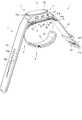
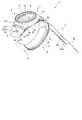
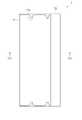
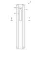
カバー9は、図22に示すように、一方向に長い袋体121と、袋体121に設けられた第1孔部122と、袋体121に設けられた第2孔部123と、を備えている。カバー9は、カーラ5及びカフ構造体6を覆うことでカーラ5及びカフ構造体6を保護する。 As shown in FIG. 22, thecover 9 includes abag body 121 elongated in one direction, afirst hole portion 122 provided in thebag body 121, and asecond hole portion 123 provided in thebag body 121. ing. Thecover 9 protects thecurler 5 and thecuff structure 6 by covering thecurler 5 and thecuff structure 6 .

袋体121は、一方向に長い矩形状の袋状に形成される。袋体121は、カフ構造体6と対向する部位が、カーラ5の外周面と対向する部位よりも高い伸縮性であって、且つ、カフ構造体6の膨張を阻害しない伸縮性を有する。ここで、カフ構造体6の膨張を阻害しない伸縮性とは、血圧測定装置1を用いて血圧を測定したときに、好適な血圧測定ができる伸縮性、換言すると、血圧測定装置1の血圧測定精度が所定の範囲を維持でき、血圧測定に適しない精度まで低下することを防止できる伸縮性である。袋体121の伸縮性は、カフ構造体6の構成や寸法等の設計値、ポンプ14の性能、その他各条件等によって適宜設定される。 Thebag body 121 is formed in a rectangular bag shape elongated in one direction. Thebag body 121 has a stretchability that is higher in the portion facing thecuff structure 6 than in the portion facing the outer peripheral surface of thecurler 5 and that does not hinder expansion of thecuff structure 6 . Here, the stretchability that does not hinder the expansion of thecuff structure 6 means the stretchability that enables suitable blood pressure measurement when the blood pressure is measured using the bloodpressure measurement device 1. In other words, the blood pressure measurement of the bloodpressure measurement device 1 The elasticity is such that the accuracy can be maintained within a predetermined range and the accuracy can be prevented from being lowered to the point of being unsuitable for blood pressure measurement. The stretchability of thebag body 121 is appropriately set according to the design values such as the configuration and dimensions of thecuff structure 6, the performance of the pump 14, other conditions, and the like.

袋体121の長手方向の内部の寸法は、カーラ5の周方向(長手方向)の長さ以上に設定される。袋体121の短手方向の内部の寸法は、カーラ5の短手方向の幅以上、好ましくは、カーラ5の短手方向の幅よりも大きく設定される。 The internal dimension of thebag body 121 in the longitudinal direction is set to be equal to or greater than the length of thecurler 5 in the circumferential direction (longitudinal direction). The inner dimension of thebag 121 in the width direction is set to be equal to or larger than the width of thecurler 5 in the width direction, preferably larger than the width of thecurler 5 in the width direction.

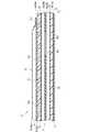
袋体121は、図23乃至図26に示すように、矩形状の一枚の布材131と、溶着シート132と、を含む。袋体121は、図23に二点鎖線で示す折り線131aのように、この一枚の布材131を、袋体121の長手方向の縁部に沿って谷折り方向に当該長手方向に対して直交する方向の縁部を折り曲げる。そして、図25及び図26に示すように、間に溶着シート132が配置するように、折り曲げた布材131の部位同士を部分的に重ね、溶着シート132で重ねられた布材131同士を溶着することで構成される。As shown in FIGS. 23 to 26, thebag body 121 includes a piece ofrectangular cloth material 131 and awelding sheet 132. As shown in FIGS. Thebag body 121 is formed by foldingasingle cloth material 131 along the edges of thebag body 121 in the longitudinal direction in a valley-fold direction, as shown by afolding line 131a indicated by a chain double-dashed line inFIG. and fold the edges perpendicular to each other. Then, as shown in FIGS. 25 and 26, the portions of the foldedcloth material 131 are partially overlapped so that thewelding sheet 132 is arranged between them, and the overlappedcloth materials 131 are welded together by thewelding sheet 132. It consists of

第1孔部122は、袋体121内にカーラ5及びカフ構造体6を挿入するときに、伸長することでカーラ5及びカフ構造体6を袋体121内に挿入可能な形状に形成される。例えば、第1孔部122は、図22に示すように、袋体121の長手方向に延びる開口か、又は、スリット状の開口である。 Thefirst hole 122 is formed into a shape that allows thecurlers 5 and thecuff structure 6 to be inserted into thebag 121 by stretching when thecurlers 5 and thecuff structure 6 are inserted into thebag 121. . For example, as shown in FIG. 22, thefirst hole 122 is an opening extending in the longitudinal direction of thebag body 121 or a slit-like opening.

第2孔部123は、図8に示すように、袋体121がカーラ5及びカフ構造体6を覆ったときに、カーラ5に設けられた給電部8の給電端子8b及び二つの給電端子8bの周囲の領域を外部に露出可能に形成される。例えば、第2孔部123は、図22に示すように、二つの給電端子8bを配置可能な円形状に形成される。 As shown in FIG. 8, when thebag 121 covers thecurler 5 and thecuff structure 6, thesecond hole 123 is provided with thepower supply terminal 8b of thepower supply section 8 provided on thecurler 5 and the two power supply terminals 8b. is formed so that the surrounding area can be exposed to the outside. For example, as shown in FIG. 22, thesecond hole 123 is formed in a circular shape in which twopower supply terminals 8b can be arranged.

矩形状の一枚の布材131は、一方向の寸法が、カーラ5の短手方向の幅の2倍の寸法及び第1孔部122の同方向の寸法の和よりも大きく、且つ、カーラ5の短手方向の幅の3倍以下に設定される。また、一枚の布材131の一方向に直交する方向の寸法が、カーラ5の周方向の寸法及び袋体121の長手方向の両端部の溶着代の寸法の和よりも大きく設定される。 The rectangular piece ofcloth material 131 has a dimension in one direction that is greater than the sum of the dimension twice the width of thecurler 5 in the transverse direction and the dimension of thefirst hole 122 in the same direction, and It is set to be three times or less the width of 5 in the lateral direction. In addition, the dimension in the direction orthogonal to one direction of thecloth material 131 is set to be larger than the sum of the circumferential dimension of thecurler 5 and the dimension of the welding allowance at both ends of thebag body 121 in the longitudinal direction.

溶着シート132は、一枚の布材131を溶着する領域の形状に形成される。溶着シート132は、所謂ホットメルトフィルムであり、加熱されることで、布材131を固定する。 Thewelding sheet 132 is formed in the shape of an area to which onecloth material 131 is to be welded. Thewelding sheet 132 is a so-called hot-melt film, and fixes thecloth material 131 by being heated.

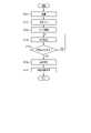
次に図27に示すように、カバー9の製造方法の一例を説明する。 Next, as shown in FIG. 27, an example of a method for manufacturing thecover 9 will be described.

先ず、図27に示すように、布材131上の溶着する部位に、溶着シート132を重ねて配置する(ステップST11)。次に、積層した布材131及び溶着シート132を図25及び図26に示すように、折り畳む(ステップST12)。具体的には、布材131の一方向の両端部を折り返して、当該端部同士重ね合わせる。この重ね合わされた端部がカーラ5の外周面に対向する部位を構成する。また、折り畳まれた布材131の端部が存する2層の布材131間には、溶着シート132が配置される。また、折りたたまれた布材131は、一方向に長い形状となる。 First, as shown in FIG. 27, thewelding sheet 132 is laid over the portion to be welded on the cloth material 131 (step ST11). Next, thelaminated cloth material 131 andwelding sheet 132 are folded as shown in FIGS. 25 and 26 (step ST12). Specifically, both ends in one direction of thecloth material 131 are folded back and overlapped with each other. This overlapped end constitutes a portion facing the outer peripheral surface of thecurler 5 . Awelding sheet 132 is arranged between the two layers ofcloth material 131 where the ends of the foldedcloth material 131 are present. Also, the foldedcloth material 131 has a shape elongated in one direction.

次に、例えば、第1溶着として、溶着シート132が介在した2層の布材131を金型で挟み込み、2層の布材131を溶着シート132により溶着する(ステップST13)。これにより、布材131は、一方向に長く、且つ、長手方向の両端が開口する形状となる。次に、2層の布材131の溶着した部位に第1孔部122及び第2孔部123を裁断する(ステップST14)。具体例として、プレス機によって、第1孔部122及び第2孔部123を打ち抜く。 Next, for example, as first welding, the two layers ofcloth material 131 with thewelding sheet 132 interposed therebetween are sandwiched between metal molds, and the two layers ofcloth material 131 are welded by the welding sheet 132 (step ST13). As a result, thecloth material 131 has a shape that is long in one direction and that both ends in the longitudinal direction are open. Next, thefirst hole portion 122 and thesecond hole portion 123 are cut at the site where the two layers ofcloth material 131 are welded (step ST14). As a specific example, thefirst hole portion 122 and thesecond hole portion 123 are punched out by a pressing machine.

次に、第2溶着として、布材131の長手方向の両端を金型で挟み込み、溶着シート132により溶着する(ステップST15)。次に、仕上げ裁断として、溶着した両端部を裁断する(ステップST16)。これらの工程によりカバー9が製造される。 Next, as the second welding, both longitudinal ends of thecloth material 131 are sandwiched between metal molds and welded by the welding sheet 132 (step ST15). Next, as finishing cutting, the welded ends are cut (step ST16). Thecover 9 is manufactured by these steps.

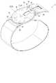
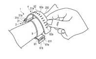
このようなカバー9のカーラ5及びカフ構造体6への取付け手順の例を説明する。先ず、第1孔部122の周囲を両手の指で摘まみ、第1孔部122を広げる。そして、第1孔部122に、カーラ5の長手側の端部からカーラ5を挿入する。なお、このとき、カーラ5の外周面側が袋体121の第1孔部122側に位置する姿勢で、第1孔部122から袋体121内にカーラ5を挿入する。カーラ5のカバー部5aよりも長手側まで挿入されたら、カーラ5が配置されていない側の袋体121の端部を引っ張り、第1孔部122を伸長させて、第1孔部122からカーラ5の短手側の端部を挿入する。これにより、カバー部5aを除くカーラ5の短手及び長手の部分がカバー9内に配置される。なお、カバー9の第2孔部123は、カバー9をカーラ5に装着することで、カーラ5に設けられた給電8の給電端子8bと対向する位置になり、給電端子8bを外部に露出させる。An example of the procedure for attaching such acover 9 to thecurler 5 and thecuff structure 6 will be described. First, the circumference of thefirst hole 122 is pinched with the fingers of both hands to widen thefirst hole 122 . Then, thecurler 5 is inserted into thefirst hole 122 from the longitudinal end of thecurler 5 . At this time, thecurlers 5 are inserted into thebag 121 through thefirst hole 122 with the outer peripheral surface of thecurlers 5 positioned on thefirst hole 122 side of thebag 121 . When thecurler 5 is inserted to the longer side than thecover portion 5a of thecurler 5, the end of thebag body 121 on the side where thecurler 5 is not arranged is pulled to extend thefirst hole portion 122, and the curler is pulled from thefirst hole portion 122. Insert the short end of 5. As a result, the short and long portions of thecurler 5 excluding thecover portion 5a are arranged inside thecover 9. As shown in FIG. When thecover 9 is attached to thecurler 5, thesecond hole 123 of thecover 9 is positioned to face thepower supply terminal 8b of thepower supplyunit 8 provided on thecurler 5, exposing thepower supply terminal 8b to the outside. Let

次に、血圧測定装置1を使用した血圧値の測定の一例について、図28乃至図31を用いて説明する。図28は、血圧測定装置1を用いた血圧測定の一例を示す流れ図であり、ユーザの動作及び制御部55の動作の双方を示す。また、図29乃至図31は、ユーザが手首200に血圧測定装置1を装着する一例を示す。 Next, an example of blood pressure value measurement using the bloodpressure measurement device 1 will be described with reference to FIGS. 28 to 31. FIG. FIG. 28 is a flowchart showing an example of blood pressure measurement using the bloodpressure measurement device 1, showing both the user's operation and thecontrol unit 55's operation. 29 to 31 show an example in which the user wears the bloodpressure measurement device 1 on thewrist 200. FIG.

なお、ユーザは、血圧測定装置1の使用に際し、予め、カバー9をカーラ5及びカフ構造体6に取り付けておく。先ず、ユーザは、手首200に血圧測定装置1を装着する(ステップST21)。具体例として、例えば、ユーザは、図29に示すように、手首200の一方をカーラ5内に挿入する。 Before using the bloodpressure measuring device 1, the user attaches thecover 9 to thecurler 5 and thecuff structure 6 in advance. First, the user wears bloodpressure measurement device 1 on wrist 200 (step ST21). As a specific example, for example, the user inserts one of thewrists 200 into thecurler 5 as shown in FIG.

このとき、血圧測定装置1は、装置本体3及びセンシングカフ73がカーラ5の相対する位置に配置されることから、センシングカフ73を手首200の手の平側の動脈210が存する領域に配置される。これにより、装置本体3及び引張カフ74は、手首200の手の甲側に配される。次いで図30に示すように、ユーザが血圧測定装置1を配した手とは反対の手によって、第1ベルト61の尾錠61bの枠状体61eに第2ベルト62を通す。次いで、ユーザは、第2ベルト62を引っ張り、カーラ5の内周面側の部材、即ち、カフ構造体6を手首200に密着させ、小孔62aにつく棒61fを挿入する。これにより、図6及び図32に示すように、第1ベルト61及び第2ベルト62が接続され、血圧測定装置1が手首200に装着される。 At this time, since the bloodpressure measurement device 1 has the devicemain body 3 and thesensing cuff 73 arranged at positions facing each other on thecurler 5 , thesensing cuff 73 is arranged in the area where theartery 210 exists on the palm side of thewrist 200 . Thereby, the devicemain body 3 and thetension cuff 74 are arranged on the back side of thewrist 200 . Next, as shown in FIG. 30, thesecond belt 62 is passed through the frame-like body 61e of thebuckle 61b of thefirst belt 61 with the hand opposite to the hand with which the bloodpressure measuring device 1 is placed. Next, the user pulls thesecond belt 62 to bring the member on the inner peripheral side of thecurler 5, that is, thecuff structure 6, into close contact with thewrist 200, and inserts therod 61f attached to thesmall hole 62a. Thereby, as shown in FIGS. 6 and 32 , thefirst belt 61 and thesecond belt 62 are connected, and the bloodpressure measuring device 1 is attached to thewrist 200 .

次に、ユーザは、操作部13を操作して、血圧値の測定開始に対応した指令の入力を行う。指令の入力操作が行われた操作部13は、測定開始に対応した電気信号を制御部55へ出力する(ステップST22)。制御部55は、当該電気信号を受信すると、例えば、第1開閉弁16A、第2開閉弁16B及び第3開閉弁16Cを開くとともに、第4開閉弁16Dを閉じ、ポンプ14を駆動し、第1流路7a、第2流路7b、第3流路7c及び第4流路7dを介して押圧カフ71、センシングカフ73及び引張カフ74へ圧縮空気を供給する(ステップST23)。これにより、押圧カフ71、センシングカフ73及び引張カフ74は膨張を開始する。 Next, the user operates theoperation unit 13 to input a command corresponding to the start of measurement of the blood pressure value. Theoperation unit 13, to which the instruction input operation has been performed, outputs an electrical signal corresponding to the start of measurement to the control unit 55 (step ST22). When thecontrol unit 55 receives the electric signal, for example, it opens the first on-offvalve 16A, the second on-offvalve 16B, and the third on-offvalve 16C, closes the fourth on-offvalve 16D, drives the pump 14, and Compressed air is supplied to thepressure cuff 71, thesensing cuff 73 and thetension cuff 74 via thefirst flow path 7a, thesecond flow path 7b, thethird flow path 7c and thefourth flow path 7d (step ST23). This causes thepressure cuff 71, thesensing cuff 73 and thetension cuff 74 to start inflating.

第1圧力センサ17A及び第2圧力センサ17Bは、押圧カフ71、センシングカフ73及び引張カフ74の圧力を検出し、この圧力に対応した電気信号を制御部55へ出力する(ステップST24)。制御部55は、受信した電気信号に基づいて、押圧カフ71、センシングカフ73及び引張カフ74の内部空間の圧力が血圧測定のための所定の圧力に達しているか否かを判断する(ステップST25)。例えば、押圧カフ71及び引張カフ74の内圧が所定の圧力に達しておらず、且つ、センシングカフ73の内圧が所定の圧力に達した場合には、制御部55は、第1開閉弁16Aを閉じ、第2流路7b、第3流路7c、第4流路7dを介して圧縮空気を供給する。 Thefirst pressure sensor 17A and thesecond pressure sensor 17B detect the pressure of thepressing cuff 71, thesensing cuff 73 and thetension cuff 74, and output an electrical signal corresponding to this pressure to the control section 55 (step ST24). Based on the received electrical signal, thecontrol unit 55 determines whether the pressure in the internal space of thepressure cuff 71, thesensing cuff 73, and thetension cuff 74 has reached a predetermined pressure for blood pressure measurement (step ST25). ). For example, when the internal pressure of thepressing cuff 71 and thetension cuff 74 has not reached a predetermined pressure and the internal pressure of thesensing cuff 73 has reached a predetermined pressure, thecontrol unit 55 closes the first opening/closing valve 16A. Closed, compressed air is supplied via thesecond flow path 7b, thethird flow path 7c, and thefourth flow path 7d.

押圧カフ71及び引張カフ74の内圧並びにセンシングカフ73の内圧が、全て所定の圧力に達した場合には、制御部55は、ポンプ14の駆動を停止する(ステップST25でYES)。このとき、図6に二点鎖線で示すように、押圧カフ71及び引張カフ74は十分に膨張しており、膨張した押圧カフ71は、背板72を押圧する。また、引張カフ74は、手首200から離間する方向に、カーラ5を押圧することから、ベルト4、カーラ5及び装置本体3は、手首200から離間する方向に移動し、結果、押圧カフ71、背板72、センシングカフ73が手首200側に引っ張られる。加えて、引張カフ74の膨張によってベルト4、カーラ5及び装置本体3が手首200から離間する方向に移動するときに、ベルト4及びカーラ5が、手首200の両側方に向かって移動し、手首200の両側方に密着した状態で、ベルト4、カーラ5及び装置本体3が移動する。このため、手首200の皮膚に密着したベルト4及びカーラ5は、手首200の両側方の皮膚を手の甲側に引っ張る。なお、カーラ5は、手首200の皮膚を引っ張ることができれば、例えば、シート部材86、106を介して間接的に手首200の皮膚に接触する構成であってもよい。 When the internal pressures of thepressure cuff 71 and thetension cuff 74 and the internal pressure of thesensing cuff 73 all reach predetermined pressures, thecontroller 55 stops driving the pump 14 (YES in step ST25). At this time, as indicated by the two-dot chain line in FIG. In addition, since thetension cuff 74 presses thecurler 5 in the direction away from thewrist 200, thebelt 4, thecurler 5, and the devicemain body 3 move in the direction away from thewrist 200. As a result, thepressure cuff 71,Back plate 72 andsensing cuff 73 are pulled towardwrist 200 . In addition, when thebelt 4, thecurler 5, and the devicemain body 3 move away from thewrist 200 due to the expansion of thetension cuff 74, thebelt 4 and thecurler 5 move toward both sides of thewrist 200, Thebelt 4, thecurler 5, and the devicemain body 3 are moved while being in close contact with both sides of thedevice 200. As shown in FIG. Therefore, thebelt 4 and thecurler 5 that are in close contact with the skin of thewrist 200 pull the skin on both sides of thewrist 200 toward the back of the hand. Thecurler 5 may be configured to indirectly contact the skin of thewrist 200 via thesheet members 86 and 106, for example, as long as the skin of thewrist 200 can be pulled.

さらに、センシングカフ73は、内圧が血圧を測定するために要する圧力となるように所定の空気量が供給され、膨張しており、そして、押圧カフ71に押圧された背板72によって手首200に向かって押圧される。このため、センシングカフ73は、手首200内の動脈210を押圧し、図32に示すように動脈210を閉塞する。 Further, thesensing cuff 73 is supplied with a predetermined amount of air so that the internal pressure becomes the pressure required for measuring blood pressure, and is inflated. pressed toward. Therefore, sensingcuff 73presses artery 210 inwrist 200 to occludeartery 210 as shown in FIG.

また、制御部55は、例えば、第3開閉弁16Cを制御し、第3開閉弁16Cの開閉を繰り返すか、又は、第3開閉弁16Cの開度を調整することで、押圧カフ71の内部空間の圧力を加圧させる。この加圧の過程において第2圧力センサ17Bが出力する電気信号に基づいて、制御部55は、最高血圧及び最低血圧等の血圧値や心拍数等の測定結果を求める(ステップST26)。制御部55は、求めた測定結果に対応した画像信号を、表示部12へ出力し、測定結果を表示部12に表示する(ステップST27)。また、制御部55は、血圧測定終了後、第1開閉弁16A、第2開閉弁16B、第3開閉弁16C及び第4開閉弁16Dを開く。 Further, thecontrol unit 55, for example, controls the third on-offvalve 16C and repeats opening and closing of the third on-offvalve 16C, or adjusts the opening degree of the third on-offvalve 16C, so that the inside of thepressure cuff 71 Increase the pressure in the space. Based on the electric signal output by thesecond pressure sensor 17B in the process of this pressurization, thecontrol unit 55 obtains blood pressure values such as the systolic blood pressure and the diastolic blood pressure, and measurement results such as the heart rate (step ST26). Thecontrol unit 55 outputs an image signal corresponding to the obtained measurement result to thedisplay unit 12, and displays the measurement result on the display unit 12 (step ST27). After the blood pressure measurement is completed, thecontrol unit 55 opens the first opening/closing valve 16A, the second opening/closing valve 16B, the third opening/closing valve 16C, and the fourth opening/closing valve 16D.

表示部12は、画像信号を受信すると、当該測定結果を画面に表示する。使用者は、表示部12を視認することで、当該測定結果を確認する。なお、使用者は、測定終了後、小孔62aからつく棒61fを外し、枠状体61eから第2ベルト62を外し、カーラ5から手首200を抜くことで、手首200から血圧測定装置1を取り外す。 Upon receiving the image signal, thedisplay unit 12 displays the measurement result on the screen. The user confirms the measurement result by viewing thedisplay unit 12 . After the measurement is completed, the user removes thestick 61f from thesmall hole 62a, removes thesecond belt 62 from the frame-like body 61e, and removes thewrist 200 from thecurler 5, thereby removing the bloodpressure measuring device 1 from thewrist 200. Remove.

このように構成された一実施形態に係る血圧測定装置1に装着するカバー9は、伸縮可能、且つ、カーラ5を配置できる長さを有する袋体121に、カーラ5を挿入可能な第1孔部122を有する構成とした。伸長することで、第1孔部122からカーラ5を挿入可能となるとともに、カーラ5に装着したときに、カーラ5のカバー部5aを除く外周面を覆うことができる。このため、カバー9は、カーラ5及びカフ構造体6が汚れることを防止できる。また、カバー9は、手首200とカフ構造体6の間に介在するため、肌触りがよく、また、布材131で形成されるとこから接触部が蒸れることがなく、血圧測定装置の装着性を向上することができる。 Thecover 9 attached to the bloodpressure measuring device 1 configured as described above has a first hole through which thecurlers 5 can be inserted into thebag body 121 that is stretchable and has a length that allows thecurlers 5 to be arranged. A configuration having aportion 122 is adopted. By extending, thecurler 5 can be inserted through thefirst hole 122, and when thecurler 5 is attached, the outer peripheral surface of thecurler 5 can be covered except for thecover portion 5a. Therefore, thecover 9 can prevent thecurler 5 and thecuff structure 6 from being soiled. In addition, since thecover 9 is interposed between thewrist 200 and thecuff structure 6, it feels good on the skin, and since it is formed of thecloth material 131, the contact portion does not get stuffy, which improves the wearability of the blood pressure measuring device. can be improved.

また、袋体121は、伸縮可能な構成であることから、カフ構造体6が膨張したときに追従して伸長することから、カフ構造体6の膨張を阻害することがない。これにより、カバー9は、血圧測定装置1の血圧の測定精度を低下させることなく、カーラ5及びカフ構造体6を覆うことができる。また、第1孔部122の周囲を伸長させることで、袋体121内にカーラ5及びカフ構造体を配置することが可能であることから、カバー9は、容易にカーラ5及びカフ構造体6に装着することが可能となる。 In addition, since thebag body 121 has an expandable structure, it expands to follow the expansion of thecuff structure 6, so that the expansion of thecuff structure 6 is not hindered. Thereby, thecover 9 can cover thecurler 5 and thecuff structure 6 without reducing the blood pressure measurement accuracy of the bloodpressure measurement device 1 . In addition, since thecurlers 5 and the cuff structure can be arranged in thebag body 121 by extending the periphery of thefirst hole 122, thecover 9 can be easily attached to thecurlers 5 and thecuff structure 6. can be installed on the

また、袋体121は、カーラ5の外周面に対向する部位で折り返された両端部が積層される一枚の布材131、並びに、布材131の積層された部位及び袋体121の長手方向の両端に設けられ、布材131を溶着するための溶着シート132により構成される。このように、一枚の布材131を溶着シート132を用いて袋状に溶着することによって袋体121を構成できることから、製造が容易となる。また、袋体121としたときにカーラ5の外周面に対向する部位に溶着シート132を配置することから、カバー9は、カーラ5の外周面に対向する部位がカーラ5の内周面に対向する部位よりも柔軟性及び伸縮性を有することになる。 In addition, thebag body 121 is composed of a sheet ofcloth material 131 in which both ends folded back at a portion facing the outer peripheral surface of thecurler 5 are laminated, and the laminated portion of thecloth material 131 and the longitudinal direction of thebag body 121 are provided at both ends of thewelding sheet 132 for welding thecloth material 131 . In this way, thebag body 121 can be constructed by welding one piece ofcloth material 131 into a bag shape using thewelding sheet 132, which facilitates manufacturing. In addition, since thewelding sheet 132 is arranged at a portion facing the outer peripheral surface of thecurler 5 when thebag body 121 is formed, the portion of thecover 9 facing the outer peripheral surface of thecurler 5 faces the inner peripheral surface of thecurler 5. It will have more flexibility and stretchability than the part where it is used.

このため、溶着シート132が設けられたカバー9のカーラ5の外周面側に対向する部位は、形状が保持されることから、カーラ5にカバー9を装着したときに、カーラ5の短手方向に位置ずれすることを防止できる。加えて、布材131のみにより構成されたカバー9のカーラ5の内周面側に対向する部位はカーラ5の外周面側に対向する部位よりも柔軟性及び伸縮性が高いことから、カフ構造体6の膨張を阻害することがない。このようなことから、カバー9は、容易に製造できるとともに、血圧測定装置1の血圧測定精度を低下させることがなく、また、血圧測定装置1の使用時にカバー9の位置ずれを防止できる。 Therefore, the portion of thecover 9 on which thewelding sheet 132 is provided, which faces the outer peripheral surface of thecurler 5 , retains its shape. positional deviation can be prevented. In addition, since the portion of thecover 9 that faces the inner peripheral surface of thecurler 5, which is composed only of thecloth material 131, has higher flexibility and stretchability than the portion that faces the outer peripheral surface of thecurler 5, the cuff structure is provided. The expansion of thebody 6 is not hindered. As described above, thecover 9 can be easily manufactured, the blood pressure measurement accuracy of the bloodpressure measurement device 1 is not lowered, and the positional deviation of thecover 9 can be prevented when the bloodpressure measurement device 1 is used.

また、袋体121は、短手方向の内部の幅が、カーラ5の短手方向の幅よりも大きく形成されることから、カーラ5及びカフ構造体6にカバー9を装着したときに、カフ構造体6が膨張したときの袋体121の伸び代を確保できる。これにより、カバー9は、袋体121が伸長したときにカフ構造体6が膨張する方向と相対する方向にカフ構造体6を押圧することを抑制できる。結果、カバー9は、カフ構造体6の膨張を阻害することなく、カーラ5及びカフ構造体6を覆うことが可能となる。 In addition, since the inner width of thebag 121 in the lateral direction is larger than the width of thecurler 5 in the lateral direction, when thecover 9 is attached to thecurler 5 and thecuff structure 6, the cuff is A margin for elongation of thebag 121 when thestructure 6 expands can be ensured. Thereby, thecover 9 can suppress pressing thecuff structure 6 in a direction opposite to the direction in which thecuff structure 6 expands when thebag 121 expands. As a result, thecover 9 can cover thecurler 5 and thecuff structure 6 without inhibiting the expansion of thecuff structure 6 .

また、カーラ5を挿入する第1孔部122及び給電端子8を露出させる第2孔部123は、布材131の二つの端部及び溶着シート132を積層した部位に設けられる。この部位は、2層の布材131及び溶着シート132によって形成されることから、袋体121のなかで、強度が高い部位となる。Afirst hole 122 for inserting thecurler 5 and asecond hole 123 for exposing thepower supply terminal8b are provided at the two ends of thecloth material 131 and thewelding sheet 132 are laminated. Since this portion is formed by the two layers of thecloth material 131 and thewelding sheet 132, the portion of thebag body 121 has a high strength.

このため、第1孔部122の開口の周囲が、伸縮性を有したまま強度が向上することから、カーラ5及びカフ構造体6を挿入する際に、第1孔部122が繰り返し伸縮されたとしても、破損することを防止できる。結果、カバー9は、繰り返し使用することができる。また、同様に、給電端子8bを露出させる第2孔部123は、袋体121の二層の布材131及び溶着シート132で形成される部位に設けられる。このため第2孔部123の開口の周囲が、伸縮性を有したまま強度が向上することから、給電端子8に接続するコネクタを給電部8の給電端子8bに繰り返し着脱したときに、コネクタにより外力が印加されても、破損することを防止できる。 Therefore, since the strength of the periphery of the opening of thefirst hole 122 is improved while maintaining elasticity, thefirst hole 122 is repeatedly stretched and contracted when thecurler 5 and thecuff structure 6 are inserted. However, damage can be prevented. As a result, thecover 9 can be used repeatedly. Similarly, asecond hole 123 for exposing thepower supply terminal 8b is provided in a portion of thebag body 121 formed by the two layers of thecloth material 131 and thewelding sheet 132 . As a result, the strength of the periphery of the opening of thesecond hole portion 123 is improved while maintaining elasticity. Damage can be prevented even when an external force is applied.

上述したように本実施形態に係る血圧測定装置1に用いられるカバー9によれば、血圧測定装置1の測定精度を低下させず、カーラ5及びカフ構造体6を容易に覆うことができる。 As described above, thecover 9 used in the bloodpressure measurement device 1 according to this embodiment can easily cover thecurler 5 and thecuff structure 6 without reducing the measurement accuracy of the bloodpressure measurement device 1 .

なお、本発明は上述した実施形態に限定されない。上述にカバー9の製造方法の一例を説明したが、これに限定されない。例えば、上述した例では、矩形状の布材131及び溶着シート132を積層させて第1溶着した後に、第1孔部122及び第2孔部123を裁断する構成を説明したがこれに限定されない。例えば、布材131の積層される両端部のそれぞれ、及び、溶着シート132に、第1孔部122及び第2孔部123を構成する孔を設け、布材131の両端及び溶着シート132を重ねたときに、これら孔を重ねることで、第1孔部122及び第2孔部123を形成してもよい。 In addition, this invention is not limited to embodiment mentioned above. Although an example of the method for manufacturing thecover 9 has been described above, the method is not limited to this. For example, in the above-described example, therectangular cloth material 131 and thewelding sheet 132 are laminated and first welded, and then thefirst hole 122 and thesecond hole 123 are cut. However, the present invention is not limited to this. . For example, holes forming thefirst hole portion 122 and thesecond hole portion 123 are provided in each of the laminated ends of thecloth material 131 and thewelding sheet 132, and the both ends of thecloth material 131 and thewelding sheet 132 are overlapped. Thefirst hole portion 122 and thesecond hole portion 123 may be formed by overlapping these holes.

即ち、本発明は、上記実施形態に限定されるものではなく、実施段階ではその要旨を逸脱しない範囲で種々に変形することが可能である。また、各実施形態は可能な限り適宜組み合わせて実施してもよく、その場合組み合わせた効果が得られる。更に、上記実施形態には種々の段階の発明が含まれており、開示される複数の構成要件における適当な組み合わせにより種々の発明が抽出され得る。 That is, the present invention is not limited to the above-described embodiments, and can be variously modified in the implementation stage without departing from the scope of the invention. Moreover, each embodiment may be implemented in combination as much as possible, and in that case, the combined effect can be obtained. Furthermore, the above-described embodiments include inventions at various stages, and various inventions can be extracted by appropriately combining a plurality of disclosed constituent elements.

1…血圧測定装置
3…装置本体
4…ベルト
5…カーラ
5a…カバー部
5b…逃げ部
5c…窪み
5d…インサート部材
5e…螺子孔
5f…孔部
5f1…第1孔部
5f2…第2孔部
5f3…第3孔部
6…カフ構造体
7…流体回路
7a…第1流路
7b…第2流路
7c…第3流路
7d…第4流路
8…給電部
8a…配線部
8b…給電端子
8c…カバー
9…カバー(血圧測定装置用カフカバー)
11…ケース
12…表示部
13…操作部
14…ポンプ
15…流路部
16…開閉弁
16A…第1開閉弁
16B…第2開閉弁
16C…第3開閉弁
16D…第4開閉弁
17…圧力センサ
17A…第1圧力センサ
17B…第2圧力センサ
18…電力供給部
19…振動モータ
20…制御基板
31…外郭ケース
31a…ラグ
31b…バネ棒
32…風防
33…基部
35…裏カバー
35a…第1締結部材
35b…第2締結部材
35c…孔部
35d…孔部
36…シール部材
41…釦
42…センサ
43…タッチパネル
51…基板
52…加速度センサ
53…通信部
54…記憶部
55…制御部
56…メインCPU
57…サブCPU
61…第1ベルト
61a…ベルト部
61b…尾錠
61c…第1孔部
61d…第2孔部
61e…枠状体
61f…つく棒
62…第2ベルト
62a…小孔
62b…第3孔部
71…押圧カフ
72…背板
72a…溝
73…センシングカフ
74…引張カフ
75…接合層
81…空気袋(袋状構造体)
81a…溶着部
81b…ブリッジ溶着部
82…被接合部
83…流路体
83a…溶着部
84…接続部
86…シート部材
86a…第1シート部材
86b…第2シート部材
86b1…開口
86c…第3シート部材
86c1…開口
86d…第4シート部材
86d1…孔部
91…空気袋(袋状構造体)
91a…溶着部
91b…接合代
92…流路体
92a…溶着部
93…接続部
96…シート部材
96a…第5シート部材
96b…第6シート部材
96b1…孔部
101…空気袋(袋状構造体)
101a…溶着部
101b…ブリッジ溶着部
102…被接合部
102a…逃げ部
103…接続部
104…切欠部
106…シート部材
106a…第7シート部材
106b…第8シート部材
106b1…開口
106c…第9シート部材
106c1…開口
106d…第10シート部材
106d1…開口
106e…第11シート部材
106e1…開口
106f…第12シート部材
106f1…開口
106g…第13シート部材
106g1…開口
106h…第14シート部材
106h1…開口
106i…第15シート部材
106i1…開口
106j…第16シート部材
106j1…開口
106k…第17シート部材
106k1…開口
106l…第18シート部材
106l1…孔部
111…第1外層
112…第1中間層
113…第2中間層
114…第2外層
121…袋体
122…第1孔部
123…第2孔部
131…布材
131a…折り線
132…溶着シート
200…手首
210…動脈
DESCRIPTION OFSYMBOLS 1... Bloodpressure measuring apparatus 3... Apparatusmain body 4...Belt 5...Curler 5a... Coverpart 5b...Relief part 5c...Recess 5d...Insert member 5e...Screw hole 5f... Hole part 5f1... First hole part 5f2... Second hole part 5f3...Third hole 6...Cuff structure 7...Fluid circuit 7a...First channel 7b...Second channel 7c...Third channel 7d...Fourth channel 8... Feedingpart 8a... Wiringpart 8b... FeedingTerminal 8c...Cover 9... Cover (cuff cover for blood pressure measuring device)
DESCRIPTION OFSYMBOLS 11...Case 12...Display part 13... Operation part 14...Pump 15... Flowpath part 16... On-offvalve 16A... First on-offvalve 16B... Second on-offvalve 16C... Third on-offvalve 16D... Fourth on-offvalve 17...Pressure Sensor 17AFirst pressure sensor 17BSecond pressure sensor 18Power supply unit 19Vibration motor 20Control board 31Outercase 31a Lug31b Spring bar 32Windshield 33Base 35Backcover 35a Third 1fastening member 35b...second fastening member 35c...hole 35d...hole 36...seal member 41...button 42...sensor 43...touch panel 51...substrate 52...acceleration sensor 53... communication section 54...storage section 55...control section 56 …Main CPU
57 Sub CPU
61First belt61a Beltportion 61b Buckle61c First hole 61dSecond hole 61e Frame-shapedbody 61f Stick 62Second belt 62aSmall hole 62bThird hole 71Pressing cuff 72Backplate 72a Groove 73Sensing cuff 74Tension cuff 75 Joininglayer 81 Air bag (bag-like structure)
81a...Weldingpart 81b...Bridge welding part 82...To-be-joined part 83...Flow path body 83a...Weldingpart 84...Connectingpart 86...Sheet member 86a...First sheet member 86b...Second sheet member 86b1...Opening 86c...Third Sheet member 86c1... Opening 86d... Fourth sheet member 86d1...Hole 91... Air bag (bag-like structure)
91a...Weldedportion 91b...Joiningallowance 92...Flow channel body 92a...Weldedpart 93...Connecting part 96...Sheet member 96a...Fifth sheet member 96b...Sixth sheet member 96b1...Hole 101...Air bag (bag-like structure )
DESCRIPTION OFSYMBOLS 101a... Weldingpart 101b...Bridge welding part 102... Joiningpart 102a...Relief part 103...Connection part 104... Notch part 106... Sheet member 106a... Seventh sheet member 106b... Eighth sheet member 106b1... Opening 106c... Ninth sheet Member 106c1... Opening 106d... Tenth sheet member 106d1... Opening 106e... Eleventh sheet member 106e1... Opening 106f... Twelfth sheet member 106f1... Opening 106g... Thirteenth sheet member 106g1... Opening 106h... Fourteenth sheet member 106h1... Opening 106i Fifteenth sheet member 106i1 Opening 106j Sixteenth sheet member 106j1 Opening 106k Seventeenth sheet member 106k1 Opening 106l Eighteenth sheetmember 106l1 Hole 111 Firstouter layer 112 Firstintermediate layer 113 Third 2Intermediate layer 114 Secondouter layer 121Bag 122First hole 123Second hole 131Cloth material131a Fold line 132Welding sheet 200Wrist 210 Artery

Claims (4)

Translated fromJapanese
手首に取り付けられる血圧測定装置用カフカバーであって、
内周面にカフ構造体が設けられ、外周面の一部に装置本体が配置されるとともに、前記外周面の前記装置本体に隣接する位置に給電端子が設けられる、前記手首の形状に倣って湾曲するカーラ及び前記カフ構造体を内部に配置可能な長さを有する一方向に長い、伸縮可能な袋状の袋体と、
前記袋体の前記カーラの外周面と対向する部位であって、且つ、前記装置本体が配置される部位に設けられ、前記袋体が伸長することで前記カフ構造体が設けられた前記カーラを挿入可能な、前記袋体の長手方向に延びる第1孔部と、
前記袋体の前記カーラの外周面に設けられた前記給電端子と対向する部位に設けられ、前記給電端子を露出させる形状に形成された第2孔部と、
を備える血圧測定装置用カフカバー。
A cuff cover for a blood pressure measuring device attached to the wrist,
A cuff structure is provided on the inner peripheral surface, a device main body is arranged on a part of the outer peripheral surface, and a power supply terminal is provided on the outer peripheral surface at a position adjacent to the device main body, following the shape of the wrist. a stretchable bag that is long in one direction and has a length that allows the curving curler and the cuff structure to be placed therein;
The curler is provided at a portion of the bag body facing the outer peripheral surface of the curler and at a portion where the apparatus main body is disposed, and the cuff structure is provided by the expansion of the bag body. an insertable first hole extending in the longitudinal direction of the bag;
a second hole provided in a portion facing the power supply terminal provided on the outer peripheral surface of the curler of the bag body and formed in a shape exposing the power supply terminal;
A cuff cover for a blood pressure measuring device, comprising:
前記袋体は、前記カーラの外周面に対向する部位で積層される一枚の布材、並びに、前記布材の前記積層される部位及び前記袋体の長手方向の両端に設けられ、前記布材を溶着するための溶着シートを有する、請求項1に記載の血圧測定装置用カフカバー。 The bag body is a piece of cloth material laminated at a portion facing the outer peripheral surface of the curler, and provided at the laminated portion of the cloth material and at both longitudinal ends of the bag body. 2. The cuff cover for a blood pressure measuring device according to claim 1, comprising a welding sheet for welding materials. 前記第1孔部及び前記第2孔部は、前記布材の積層される部位に設けられる、請求項2に記載の血圧測定装置用カフカバー。 3. The cuff cover for a blood pressure measuring device according to claim 2, wherein said first hole and said second hole are provided in a portion where said cloth material is laminated. 前記袋体は、短手方向の幅が、前記カーラの短手方向の幅よりも大きく形成される、請求項1に記載の血圧測定装置用カフカバー。 2. The cuff cover for a blood pressure measuring device according to claim 1, wherein said bag body has a width in the lateral direction larger than the width in the lateral direction of said curler.
JP2018246187A2018-12-272018-12-27 Cuff cover for blood pressure measuring deviceActiveJP7150595B2 (en)

Priority Applications (5)

Application NumberPriority DateFiling DateTitle
JP2018246187AJP7150595B2 (en)2018-12-272018-12-27 Cuff cover for blood pressure measuring device
PCT/JP2019/048038WO2020137482A1 (en)2018-12-272019-12-09Cuff cover for blood pressure measurement device
CN201980080139.2ACN113194822B (en)2018-12-272019-12-09Sleeve belt cover for blood pressure measuring device
DE112019005574.7TDE112019005574T5 (en)2018-12-272019-12-09 CUFF COVER FOR BLOOD PRESSURE MEASURING DEVICE
US17/304,501US12114965B2 (en)2018-12-272021-06-22Cuff cover for blood pressure measurement device

Applications Claiming Priority (1)

Application NumberPriority DateFiling DateTitle
JP2018246187AJP7150595B2 (en)2018-12-272018-12-27 Cuff cover for blood pressure measuring device

Publications (2)

Publication NumberPublication Date
JP2020103645A JP2020103645A (en)2020-07-09
JP7150595B2true JP7150595B2 (en)2022-10-11

Family

ID=71129770

Family Applications (1)

Application NumberTitlePriority DateFiling Date
JP2018246187AActiveJP7150595B2 (en)2018-12-272018-12-27 Cuff cover for blood pressure measuring device

Country Status (5)

CountryLink
US (1)US12114965B2 (en)
JP (1)JP7150595B2 (en)
CN (1)CN113194822B (en)
DE (1)DE112019005574T5 (en)
WO (1)WO2020137482A1 (en)

Families Citing this family (5)

* Cited by examiner, † Cited by third party
Publication numberPriority datePublication dateAssigneeTitle
US20210321889A1 (en)*2020-04-162021-10-21Apple Inc.Stretchable Blood Pressure Cuff
JP7468223B2 (en)*2020-07-272024-04-16オムロンヘルスケア株式会社 Blood Pressure Cuff
CN113143234B (en)*2021-04-132023-04-14研和智能科技(杭州)有限公司Blood pressure measuring device and control method
JP7673498B2 (en)*2021-05-282025-05-09オムロンヘルスケア株式会社 Cuff Cover
CN116035544A (en)*2022-12-302023-05-02Oppo广东移动通信有限公司Wearable electronic equipment and control method thereof

Citations (3)

* Cited by examiner, † Cited by third party
Publication numberPriority datePublication dateAssigneeTitle
JP3139521U (en)2007-02-252008-02-21株式会社松屋R&D Sanitary cover for cuff
JP1615126S (en)2017-12-272018-10-09
JP1640133S (en)2018-12-172019-09-02

Family Cites Families (11)

* Cited by examiner, † Cited by third party
Publication numberPriority datePublication dateAssigneeTitle
JPH09238910A (en)*1996-03-081997-09-16Citizen Watch Co LtdCuff for wrist hemomanometer
JPH1033491A (en)*1996-07-291998-02-10Terumo CorpCuff for measuring blood pressure
JPH11197123A (en)*1998-01-131999-07-27Omron CorpIntegrated type sphygmomanometer
JP5169552B2 (en)*2008-07-072013-03-27オムロンヘルスケア株式会社 Cuff for blood pressure information measuring device and blood pressure information measuring device provided with the same
US20100298724A1 (en)*2009-05-192010-11-25Welch Allyn, Inc.Recyclable or biodegradable blood pressure cuff
US8652057B2 (en)*2009-05-192014-02-18Welch Allyn, Inc.Recyclable or biodegradable blood pressure cuff
JP4414485B1 (en)*2009-10-162010-02-10テルモ株式会社 Sphygmomanometer with cuff device
JP6051964B2 (en)*2013-03-072016-12-27オムロンヘルスケア株式会社 Blood pressure measurement cuff and method for manufacturing blood pressure measurement cuff
JP2015066293A (en)*2013-09-302015-04-13ミナト医科学株式会社 Armband for blood pressure measurement
CN204121003U (en)*2014-10-202015-01-28吴跃进General detachable blood pressure cuff
CN204562133U (en)*2015-02-272015-08-19华中科技大学同济医学院附属协和医院Detachable Wrist blood pressure meter protective sleeve for cuff

Patent Citations (3)

* Cited by examiner, † Cited by third party
Publication numberPriority datePublication dateAssigneeTitle
JP3139521U (en)2007-02-252008-02-21株式会社松屋R&D Sanitary cover for cuff
JP1615126S (en)2017-12-272018-10-09
JP1640133S (en)2018-12-172019-09-02

Also Published As

Publication numberPublication date
DE112019005574T5 (en)2021-08-12
US20210307627A1 (en)2021-10-07
JP2020103645A (en)2020-07-09
CN113194822A (en)2021-07-30
CN113194822B (en)2024-02-13
US12114965B2 (en)2024-10-15
WO2020137482A1 (en)2020-07-02

Similar Documents

PublicationPublication DateTitle
JP7150595B2 (en) Cuff cover for blood pressure measuring device
JP7237576B2 (en) Blood pressure measuring device
CN111511275A (en)Blood pressure measuring device
JP7094876B2 (en) Manufacturing method of cuff for blood pressure measuring device
CN111526783A (en)Blood pressure measuring device
WO2020137483A1 (en)Blood pressure measurement device
JP7094875B2 (en) Blood pressure measuring device
CN112689472B (en) Blood pressure measuring device
JP7175738B2 (en) Blood pressure measuring device
JP7202886B2 (en) Blood pressure measuring device
JP7278814B2 (en) Cuff unit, cuff unit manufacturing method, and blood pressure measuring device
JP7237574B2 (en) Blood pressure measuring device
JP7202885B2 (en) Blood pressure measuring device
CN111511276A (en)Blood pressure measuring device

Legal Events

DateCodeTitleDescription
A521Request for written amendment filed

Free format text:JAPANESE INTERMEDIATE CODE: A523

Effective date:20211223

A621Written request for application examination

Free format text:JAPANESE INTERMEDIATE CODE: A621

Effective date:20211223

TRDDDecision of grant or rejection written
A01Written decision to grant a patent or to grant a registration (utility model)

Free format text:JAPANESE INTERMEDIATE CODE: A01

Effective date:20220830

A61First payment of annual fees (during grant procedure)

Free format text:JAPANESE INTERMEDIATE CODE: A61

Effective date:20220928

R150Certificate of patent or registration of utility model

Ref document number:7150595

Country of ref document:JP

Free format text:JAPANESE INTERMEDIATE CODE: R150


[8]ページ先頭

©2009-2025 Movatter.jp