JP7149812B2 - Power control circuit, power control system, and power control method - Google Patents
Power control circuit, power control system, and power control methodDownload PDFInfo
- Publication number
- JP7149812B2 JP7149812B2JP2018209630AJP2018209630AJP7149812B2JP 7149812 B2JP7149812 B2JP 7149812B2JP 2018209630 AJP2018209630 AJP 2018209630AJP 2018209630 AJP2018209630 AJP 2018209630AJP 7149812 B2JP7149812 B2JP 7149812B2
- Authority
- JP
- Japan
- Prior art keywords
- fuel cell
- power
- unit
- activation
- storage battery
- Prior art date
- Legal status (The legal status is an assumption and is not a legal conclusion. Google has not performed a legal analysis and makes no representation as to the accuracy of the status listed.)
- Active
Links
Images


Classifications
- Y—GENERAL TAGGING OF NEW TECHNOLOGICAL DEVELOPMENTS; GENERAL TAGGING OF CROSS-SECTIONAL TECHNOLOGIES SPANNING OVER SEVERAL SECTIONS OF THE IPC; TECHNICAL SUBJECTS COVERED BY FORMER USPC CROSS-REFERENCE ART COLLECTIONS [XRACs] AND DIGESTS
- Y02—TECHNOLOGIES OR APPLICATIONS FOR MITIGATION OR ADAPTATION AGAINST CLIMATE CHANGE
- Y02B—CLIMATE CHANGE MITIGATION TECHNOLOGIES RELATED TO BUILDINGS, e.g. HOUSING, HOUSE APPLIANCES OR RELATED END-USER APPLICATIONS
- Y02B90/00—Enabling technologies or technologies with a potential or indirect contribution to GHG emissions mitigation
- Y02B90/10—Applications of fuel cells in buildings
Landscapes
- Stand-By Power Supply Arrangements (AREA)
- Supply And Distribution Of Alternating Current (AREA)
- Charge And Discharge Circuits For Batteries Or The Like (AREA)
Description
Translated fromJapanese本発明の実施形態は、電力制御回路、電力制御システム、及び、電力制御方法に関する。TECHNICAL FIELD Embodiments of the present invention relate to power control circuits, power control systems, and power control methods.
電力供給事業者から需要家に電力消費抑制要請を実施するデマンドレスポンス(Demand Response:DR)と称される電力需給調整が注目されている。特許文献1には、デマンドレスポンスに応じた電力管理を行うための電力管理システム等に係る技術が開示されている。Electricity supply and demand adjustment called Demand Response (DR), in which electric power suppliers request consumers to curb electric power consumption, is drawing attention. Patent Literature 1 discloses a technology related to a power management system and the like for performing power management according to demand response.
デマンドレスポンスを用いた電力需給調整に燃料電池を用いる場合、デマンドレスポンスを要請する要請信号をトリガとして燃料電池を起動することを用いて商用電力を抑制する方法が考えられる。本開示では、燃料電池を用いた給電への切り替えが瞬断なく行える技術を提供する。When a fuel cell is used for power supply and demand adjustment using demand response, a method of suppressing commercial power by activating the fuel cell with a request signal requesting demand response as a trigger is conceivable. The present disclosure provides a technology that enables switching to power supply using a fuel cell without interruption.
例示的実施形態においては、電力制御回路が提供される。この電力制御回路は、取得部と開始部と受信部と切替部とを備える。取得部は、デマンドレスポンスの発動予測に基づいたデマンドレスポンスの発動予定時刻を取得する。開始部は、取得部における発動予定時刻の取得に応じて、発動予定時刻に又は発動予定時刻の前に燃料電池が起動状態に至ることができるタイミングにおいて、燃料電池の起動を発動予定時刻の前に予め開始する。受信部は、デマンドレスポンスの発動通知を受信する。切替部は、受信部における発動通知の受信に応じて、外部負荷側への給電を燃料電池側からの給電に切り替える。In an exemplary embodiment, a power control circuit is provided. The power control circuit comprises an acquisition section, an initiation section, a reception section and a switching section. The acquisition unit acquires the scheduled activation time of the demand response based on the prediction of the activation of the demand response. According to the acquisition of the scheduled activation time by the acquisition unit, the initiation unit activates the fuel cell before the scheduled activation time at the scheduled activation time or at a timing at which the fuel cell can reach the activation state before the scheduled activation time. to start in advance. The receiving unit receives the notification of activation of the demand response. The switching unit switches power supply to the external load side to power supply from the fuel cell side in response to reception of the activation notification by the receiving unit.
従って、デマンドレスポンスの発動予定時刻の取得に応じて燃料電池の起動を発動予定時刻の前に予め開始し、発動予定時刻に又は発動予定時刻の前には燃料電池が起動状態に至ることができる。従って、発動予定時刻には既に燃料電池が起動状態となっており、よって商用電力系統側と燃料電池側との間でデマンドレスポンスに応じた供給電力の切り替えがスムーズに行い得る。Therefore, in response to acquisition of the scheduled activation time of the demand response, activation of the fuel cell can be started in advance before the scheduled activation time, and the fuel cell can reach the activated state at or before the scheduled activation time. . Therefore, the fuel cell is already in the activated state at the scheduled activation time, so that the supply power can be smoothly switched between the commercial power system side and the fuel cell side according to the demand response.
本開示によれば、燃料電池を用いた給電への切り替えが瞬断なく行える。According to the present disclosure, switching to power supply using a fuel cell can be performed without interruption.
以下、図面を参照して種々の実施形態について詳細に説明する。なお、各図面において同一または相当の部分に対しては同一の符号を附すこととする。Various embodiments are described in detail below with reference to the drawings. In each drawing, the same reference numerals are given to the same or corresponding parts.
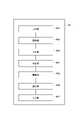
図1を参照して例示的実施形態に係る電力制御システム1の構成を説明する。電力制御システム1は、商用電力系統2、交流分電盤3、燃料電池装置4、無停電電源装置5、外部負荷6を備える。商用電力系統2は交流分電盤3に接続され、交流分電盤3は燃料電池装置4に接続される。燃料電池装置4は無停電電源装置5に接続され、無停電電源装置5は外部負荷6に接続される。A configuration of a power control system 1 according to an exemplary embodiment will be described with reference to FIG. The power control system 1 includes a
商用電力系統2は、商用の交流電力を供給する。交流分電盤3は、商用電力系統2から供給される交流電力を二つ以上の系統に分電する。The
燃料電池装置4は、停電センサ4a、逆潮流防止回路4b、コンバータ4c、燃料電池4dを備える。燃料電池装置4は、更に、インバータ4e、給電切替回路4f、蓄電池4g、電力制御回路4h、直流バス4iを備える。The
停電センサ4aは、交流分電盤3に接続される。逆潮流防止回路4bは、停電センサ4aに接続される。コンバータ4cは、逆潮流防止回路4bに接続される。The
燃料電池4dは、コンバータ4cと蓄電池4gとに接続される。蓄電池4gとコンバータ4cとは、直流バス4iを介して燃料電池4dに並列に接続される。燃料電池4dは、更にインバータ4eに接続される。The
インバータ4eは、給電切替回路4fに接続される。給電切替回路4fには、インバータ4eと交流分電盤3とが並列に接続される。給電切替回路4fは、無停電電源装置5に接続される。無停電電源装置5は、外部負荷6に接続される。The
停電センサ4aは、交流分電盤3から受ける商用電力系統2側の電圧を検出し、検出結果を電力制御回路4hに通知する。逆潮流防止回路4bは、電力制御回路4hからの指示に応じて、燃料電池装置4側を、商用電力系統2側から切り離す、又は、商用電力系統2側に接続する。The
コンバータ4cは、燃料電池4dからの直流バス4iに接続される。コンバータ4cは、商用電力系統2から供給される交流電力を直流電力に変換する。コンバータ4cは、電力制御回路4hからの指示に応じて駆動する。コンバータ4cは、電力制御回路4hからの指示に応じて、コンバータ4cの出力電圧(第2出力電圧)を変更し得る。
燃料電池4dは、固形酸化物形燃料電池(SOFC)、固体高分子形燃料電池(PEFC)等の燃料電池であり得る。燃料電池4dは、直流電圧を出力する。燃料電池4dは、電流センサ4d1を備える。燃料電池4dは、電力制御回路4hからの指示に応じて駆動する。燃料電池4dは、電力制御回路4hからの指示に応じて、燃料電池4dの出力電圧(第1出力電圧)を変更し得る。The
電流センサ4d1は、燃料電池4dの出力電流を検出し、燃料電池4dは、電流センサ4d1の検出結果に基づいて燃料電池4dの起動(運転)の停止等を行う。燃料電池4dの起動とは、燃料電池4dを起動させることを意味する。燃料電池4dは、電流センサ4d1において検出された出力電流が予め設定された基準値を下回ると、停止する。The current sensor 4d1 detects the output current of the
インバータ4eは、燃料電池4dから出力される直流電力を交流電力に変換する。インバータ4eは、電力制御回路4hからの指示に応じて駆動する。The
給電切替回路4fは、燃料電池4d側及び商用電力系統2側と外部負荷6側とに接続される。給電切替回路4fは、電力制御回路4hからの指示に応じて駆動する。給電切替回路4fは、電力制御回路4hからの指示に応じて、外部負荷6側への給電を、燃料電池4d側からの給電(インバータ4eから出力される交流電圧の給電)と、商用電力系統2側からの給電との何れかに切り替える。The power
蓄電池4gは、直流バス4iを介してコンバータ4cと燃料電池4dに並列に接続される。蓄電池4gは、蓄電池4gの充電容量等の状態を、電力制御回路4hに通知する。A
電力制御回路4hは、例えばHome Energy Management System(HEMS)として機能し得る。電力制御回路4hは、物理的には、CPU、ROM、RAM、通信装置等を含むハードウエア(図4参照)を備え得る。電力制御回路4hは、このようなハードウエアを用いて、電力制御回路4hが行う動作・機能を実現する。The
電力制御回路4hは、商用電力系統の電圧(停電センサ4aからの検出結果)を停電センサ4aから受ける。電力制御回路4hは、蓄電池4gの充電容量等の状態を示す通知を蓄電池4gから受ける。電力制御回路4hは、逆潮流防止回路4b、コンバータ4c、インバータ4e、燃料電池4d、給電切替回路4fの各々の動作を制御する。The
電力制御回路4hは、デマンドレスポンスの発動を予測した発動予測に基づいたデマンドレスポンスの発動予定時刻(デマンドレスポンスの発動を通知する発動通知が電力制御回路4hによって受信されることが予定される時刻を示すデータ)を取得(算出)する。The
この発動予定時刻は、電力供給事業者が提示する電力予測使用率、卸電力取引所における電力卸価格等、電力需要に関連性の高いパラメータを用いて、ニューラルネットワークやロジスティック回帰を用いて算出され得る。電力制御回路4hは、インターネットに接続が可能であり、例えば、外部のアグリゲータサーバからデマンドレスポンスの発動通知を受信する。This scheduled activation time is calculated using neural networks and logistic regression using parameters that are highly related to power demand, such as the predicted power usage rate presented by the power supplier and the wholesale power price on the wholesale power exchange. obtain. The
無停電電源装置5は、給電切替回路4fにおいて給電の切り替えがある場合であっても、瞬断無く外部負荷6側に給電を行う回路を備える。無停電電源装置5は、例えばUninterruptible Power Supply(UPS)と称される装置であり得る。The uninterruptible power supply 5 includes a circuit that supplies power to the
外部負荷6は、無停電電源装置5に接続された配電盤と、この配電盤に接続された複数の負荷装置とを備える。電力制御システム1が例えば通信事業者の基地局に用いられる装置である場合、複数の負荷装置は、一例としてバックアップ機器、照明機器、空調機器等を含み得る。The
電力制御回路4hは、図2に示すように、機能的には、取得部4h1、開始部4h2、受信部4h3、切替部4h4、調整部4h5、監視部4h6、停止部4h7を備える。As shown in FIG. 2, the
取得部4h1は、デマンドレスポンスの発動予測に基づいたデマンドレスポンスの発動予定時刻を取得(算出)する。The acquisition unit 4h1 acquires (calculates) the scheduled activation time of the demand response based on the prediction of the activation of the demand response.
開始部4h2は、取得部4h1における発動予定時刻の取得に応じて、発動予定時刻に又は発動予定時刻の前に燃料電池4dが起動状態に至ることができるタイミングで、燃料電池4dの起動を発動予定時刻の前に予め開始する。開始部4h2は、燃料電池4dの起動の開始の指示として、起動信号を燃料電池4dに送出する。The starting unit 4h2 activates the activation of the
受信部4h3は、外部のアグリゲータサーバから、発動通知を受信する。切替部4h4は、逆潮流防止回路4bを駆動して、商用電力系統2側と燃料電池4d側との接続のオン・オフを行う。切替部4h4は、給電切替回路4fを駆動して、外部負荷6側への給電を燃料電池4d側からの給電に切り替える。The receiving unit 4h3 receives an activation notification from an external aggregator server. The switching unit 4h4 drives the reverse power
特に、切替部4h4は、受信部4h3におけるデマンドレスポンスの発動通知の受信に応じて、及び、監視部4h6における停電の判定に応じて、外部負荷6側への給電を燃料電池4d側からの給電に切り替える。In particular, the switching unit 4h4 switches power supply to the
調整部4h5、コンバータ4c及び燃料電池4dの各々の出力電圧を調整する。調整部4h5は、燃料電池4dの第1出力電圧とコンバータ4cの第2出力電圧とを調整することを用いて、蓄電池4gの充電容量及び充電速度を調整する。It adjusts the output voltage of each of the adjustment unit 4h5, the
調整部4h5は、燃料電池4dの起動開始から起動状態に至るまで蓄電池4gへの充電を燃料電池4dが継続して行えるために、蓄電池4gの充電容量及び充電速度を調整する。The adjusting unit 4h5 adjusts the charge capacity and charging speed of the
従って、燃料電池4dの起動開始から起動状態に至るまで燃料電池4dの動作を停止せずに継続させ得る。このため、外部負荷6側への給電が燃料電池4d側からの給電に切り替えられて燃料電池4dが起動状態に至ると、外部負荷6側への給電が燃料電池4d側から瞬断無く可能となる。Therefore, the operation of the
調整部4h5は、蓄電池4gへの充電が燃料電池4dの起動開始から行われる場合に発動予定時刻の経過のタイミングにおいて充電完了となるように、蓄電池4gの充電容量及び充電速度を調整し得る。蓄電池4gへの充電が完了すると、燃料電池4dの出力電流が基準値を下回るので、燃料電池4dは停止する。The adjustment unit 4h5 can adjust the charging capacity and charging speed of the
従って、デマンドレスポンスの発動予定時刻が経過してもデマンドレスポンスの発動通知が受信されない場合、電力制御回路4hからの指示(電力制御回路4hが行う管理)が無くても、燃料電池4dを停止させ得る。Therefore, if the notification of activation of the demand response is not received even after the expected activation time of the demand response has passed, the
監視部4h6は、停電センサ4aからの検出結果(商用電力系統2側の電圧)を用いて、商用電力系統2側の電圧を監視する。監視部4h6は、商用電力系統2側の電圧喪失を検知する。監視部4h6は、商用電力系統2側の電圧喪失を検知すると、停電が生じたと判定する。監視部4h6は、商用電力系統2側の電圧復帰を検知すると、復電されたと判定する。The monitoring unit 4h6 monitors the voltage on the
開始部4h2は、停電が生じたと監視部4h6が判定した場合に、燃料電池4dに起動信号を送出して燃料電池4dの起動を開始する。切替部4h4は、停電が生じたと監視部4h6が判定した場合に、給電切替回路4fを駆動して外部負荷6側への給電を燃料電池4d側からの給電に切り替える。When the monitoring unit 4h6 determines that a power failure has occurred, the starting unit 4h2 sends a start signal to the
燃料電池4dは、停電が生じたと監視部4h6が判定した場合に外部負荷6側への給電が燃料電池4d側からの給電に切り替わると、燃料電池4dが起動状態に至るまで蓄電池4gから給電を受けつつ当該給電を外部負荷6側に供給する。When the monitoring unit 4h6 determines that a power failure has occurred and the power supply to the
なお、監視部4h6は、商用電力系統2側の電圧喪失を検知してから予め設定された第1待機期間が経過した後に、停電が生じたと判定する。この構成のために、監視部4h6が検知した商用電力系統2側の電圧喪失が瞬間的であって実質的な停電には該当し得ない場合に、燃料電池4dの起動が回避され得る。監視部4h6は、商用電力系統2側の電圧復帰を検知してから予め設定された第2待機期間が経過した後に、復電したと判定する。Note that the monitoring unit 4h6 determines that a power outage has occurred after a preset first standby period has elapsed since the voltage loss on the
停止部4h7は、燃料電池4dの起動(運転)を停止する。停止部4h7は、燃料電池4dの起動(運転)の停止の指示として、停止信号を燃料電池4dに送出する。The stopping unit 4h7 stops starting (operating) the
図3を参照して、例示的実施形態に係る電力制御方法MTについて説明する。電力制御方法MTは、電力制御回路4hが実行する。電力制御方法MTは、ステップS1~S5,S5a,S6~S13を備える。A power control method MT according to an exemplary embodiment will now be described with reference to FIG. The power control method MT is executed by the
電力制御方法MTは、外部負荷6側への給電が商用電力系統2側からの給電を用いて行われている場合から開始される。この場合、商用電力系統2側の交流電力がコンバータ4cから燃料電池4d及び蓄電池4gに出力される。この交流電力は、燃料電池4dにスタンバイ給電されるとともに蓄電池4gにも給電される。蓄電池4gは、コンバータ4cの出力電圧に応じてある一定のState Of Charge (SOC)に保たれる。The power control method MT is started when power supply to the
まず、監視部4h6は、停電センサ4aにおいて得られる検出結果に基づいて商用電力系統2側の電圧を監視し、停電が生じたか否かを判定する(ステップS1)。ステップS1において、監視部4h6は、停電センサ4aの検出結果が商用電力系統2側の電圧喪失を示す場合であっても、この電圧喪失の継続期間が予め設定された期間(例えば10秒間)に満たない場合には、当該電圧喪失は実質的な停電には該当しない、と判定する。First, the monitoring unit 4h6 monitors the voltage on the
停電は生じていなと監視部4h6が判定すると(ステップS1;NO)、取得部4h1は、デマンドレスポンスの発動予定時刻を取得したか否かを判定する(ステップS2)。発動予定時刻は取得されていないと取得部4h1が判定した場合(ステップS2;NO)、燃料電池装置4及び蓄電池4gへの給電が継続され(ステップS3)、ステップS1に移行される。When the monitoring unit 4h6 determines that a power failure has not occurred (step S1; NO), the acquisition unit 4h1 determines whether or not the scheduled activation time of the demand response has been acquired (step S2). When the acquisition unit 4h1 determines that the scheduled activation time has not been acquired (step S2; NO), power supply to the
ステップS2において、発動予定時刻は取得されたと取得部4h1が判定した場合(ステップS2;YES)、開始部4h2は、燃料電池4dの起動を開始する(ステップS4)。この場合、開始部4h2は、デマンドレスポンスの発動予定時刻の取得に応じて、発動予定時刻に又は発動予定時刻の前に燃料電池4dが起動状態に至ることができるタイミングにおいて、燃料電池4dの起動を発動予定時刻の前に予め開始する。In step S2, when the acquisition unit 4h1 determines that the scheduled activation time has been acquired (step S2; YES), the start unit 4h2 starts activation of the
このように、開始部4h2は、発動予定時刻に基づき燃料電池4dを発動予定時刻の前に予め起動しておく。すなわち、開始部4h2は、発動予定時刻をもとに燃料電池4dの起動期間T(燃料電池4dが起動を開始してから起動状態に至るまでの期間)を勘案して事前に燃料電池4dに起動信号を与え、燃料電池4dは起動を開始する。In this manner, the starting unit 4h2 activates the
例えば発動予定時刻が現在から60分後であって燃料電池4dの起動期間Tが20分間である場合に、現在から40分後に開始部4h2が燃料電池4dに起動信号を送出する。For example, if the scheduled activation time is 60 minutes from now and the activation period T of the
なお、発動予定時刻に到達するまでの間、燃料電池4dが停止しないように、調整部4h5は、蓄電池4gの充電容量を予め調整している。例えば起動期間Tが20分間の場合、発動予定時刻に到達するまでの間、燃料電池4dが停止しないように、調整部4h5がコンバータ4c及び燃料電池4dの各々の出力電圧の調整(例えば、コンバータ4cの出力電圧を46[V]、燃料電池4dの出力電圧を52[V]に調整)を行う。この調整は、燃料電池4dが停止しない程度(燃料電池4dの出力電流が基準値を下回らない程度)に蓄電池4gの充電容量を残す。Note that the adjustment unit 4h5 adjusts the charge capacity of the
燃料電池4dの出力電圧は、蓄電池4gの電圧(コンバータ4cの出力電圧)に比べて高く設定される。このため、燃料電池4dから蓄電池4gに給電が行われ、蓄電池4gが充電される。従って、発動予定時刻となり外部負荷6側への給電が燃料電池4d側からの給電に切り替わるまでの間も、燃料電池4dの出力は継続することとなり、よって、デマンドレスポンスの発動に対し燃料電池4dは速やかに応答することが可能となる。The output voltage of the
なお、上記のように、発動予定時刻に到達するまでの間に行われる蓄電池4gの充電においては、蓄電池4gが過充電とならないように蓄電池4gの充電容量が決定されることが必要になると共に燃料電池4dの出力電圧が燃料電池4dの入力電圧の許容範囲を上回らないように設計されることが必要となる。As described above, in charging the
ステップS4の後、受信部4h3は、デマンドレスポンスの発動通知を受信したか否かを判定する(ステップS5)。受信部4h3は、発動通知を受信していないと判定した場合(ステップS5;NO)、ステップS5aに移行する。After step S4, the receiving unit 4h3 determines whether or not a demand response activation notification has been received (step S5). When the reception unit 4h3 determines that the activation notification has not been received (step S5; NO), the process proceeds to step S5a.
ステップS5aは、発動予定時刻になっても受信部4h3が発動通知を受信しない場合に、タイマー制御を用いて燃料電池4dを停止させるステップである。ステップS5aにおいて、停止部4h7は、第3待機期間が終了したか否かを判定する(ステップS5a)。第3待機期間は、燃料電池4dを停止させずに発動通知の受信を待機する期間であり、予め設定された期間である。Step S5a is a step of stopping the
一実施形態において、第3待機期間は、燃料電池4dの起動の開始から発動予定時刻に至るまでの期間(又は燃料電池4dの起動の開始から発動予定時刻に予め設定された時間を加えた期間)であり得る。例えば、第3待機期間は、燃料電池4dの起動の開始から、60分後の発動予定時刻に更に5分が加えられた65分後に至るまでの期間であり得る。In one embodiment, the third standby period is a period from the start of activation of the
ステップS5aにおいて、停止部4h7は、第3待機期間が終了していないと判定した場合(ステップS5a;NO)、ステップS5に移行する。ステップS5aにおいて、停止部4h7は、第3待機期間が終了したと判定した場合(ステップS5a;YES)、燃料電池4dに停止信号を送出して燃料電池4dを停止し(ステップS6)、ステップS1に移行する。燃料電池4dが停止した後には、蓄電池4gはコンバータ4cの出力電圧に応じたSOCに到達するまで燃料電池4dに給電し、その後、コンバータ4cから燃料電池4dに給電する。In step S5a, when the stopping unit 4h7 determines that the third standby period has not ended (step S5a; NO), the process proceeds to step S5. In step S5a, when the stopping unit 4h7 determines that the third waiting period has ended (step S5a; YES), it sends a stop signal to the
なお、発動予定時刻に至っても受信部4h3が発動通知を受信しない場合、直流バス4iに接続されるコンバータ4cの出力電圧を調整部4h5が調整して蓄電池4gの充電容量を適切に定めれば、ステップS5aを用いずに燃料電池4dを停止させ得る。コンバータ4c及び燃料電池4dの各々の出力電圧の調整を調整部4h5が行えば蓄電池4gの充電容量は好適に残され得る。If the receiving unit 4h3 does not receive the activation notification even at the scheduled activation time, the adjustment unit 4h5 adjusts the output voltage of the
例えば、コンバータ4cの出力電圧を48[V]に調整し、燃料電池4dの出力電圧を52[V]に調整する処理を調整部4h5が行えば蓄電池4gの充電容量は好適に残され得る。燃料電池4dの起動が開始された後、蓄電池4gは48[V]から52[V]に至るまで燃料電池4dから充電される。For example, if the adjustment unit 4h5 adjusts the output voltage of the
この場合、燃料電池4dが蓄電池4gを充電するのに要する充電期間Kは、コンバータ4cの出力電圧に基づいて一意に決まる。コンバータ4cの出力電圧が低いほど充電期間Kは長く、コンバータ4cの出力電圧が高いほど充電期間Kは短い。充電期間Kが燃料電池4dの既知の起動期間Tとなるように調整部4h5がコンバータ4c及び燃料電池4dの各々の出力電圧を調整すれば、上記したように、発動予定時刻に至っても受信部4h3が発動通知を受信しない場合においてもステップS5aの処理を用いずに燃料電池4dを停止させ得る。In this case, the charging period K required for the
ステップS5において、発動通知を受信したと受信部4h3が判定した場合(ステップS5;YES)、切替部4h4は、給電切替回路4fを駆動して外部負荷6側への給電を燃料電池4d側からの給電に切り替える(ステップS7)。ステップS7の後、受信部4h3は、デマンドレスポンスを解除する旨を示す解除通知を受信したか否かを判定する(ステップS8)。In step S5, if the receiving unit 4h3 determines that it has received the activation notification (step S5; YES), the switching unit 4h4 drives the power
ステップS8において、受信部4h3は、解除通知を受信したと判定するまでステップS8の処理を繰り返す(ステップS8;NO)。ステップS8において、解除通知を受信したと受信部4h3が判定した場合(ステップS8;YES)、切替部4h4は、給電切替回路4fを駆動して外部負荷6側への給電を商用電力系統2側からの給電に切り替えて(ステップS9)、ステップS6に移行する。In step S8, the receiving unit 4h3 repeats the process of step S8 until it determines that the release notification has been received (step S8; NO). In step S8, if the receiving unit 4h3 determines that it has received the release notification (step S8; YES), the switching unit 4h4 drives the power
ステップS1に戻って説明する。ステップS1において、停電が生じたと監視部4h6が判定すると(ステップS1;YES)、開始部4h2は燃料電池4dに起動信号を送出して燃料電池4dの起動を開始すると共に(ステップS10)、切替部4h4は給電切替回路4fを駆動して外部負荷6側への給電を燃料電池4d側からの給電に切り替える(ステップS11)。Returning to step S1, description will be made. In step S1, when the monitoring unit 4h6 determines that a power failure has occurred (step S1; YES), the starting unit 4h2 sends a start signal to the
監視部4h6は、ステップS1において、商用電力系統2側の電圧喪失を検知してから予め設定された第1待機期間が経過した後に、停電が生じたと判定する。停電と判定するまでに監視部4h6が予め設定された第1待機期間(例えば10秒)の経過を待つ理由は、実質的な停電に該当し得ない瞬停等の場合を除外するためである。In step S1, the monitoring unit 4h6 determines that a power failure has occurred after a first standby period set in advance has elapsed since the voltage loss on the
監視部4h6が停電と判断した場合、切替部4h4は、逆潮流防止回路4bを駆動して燃料電池4d側を商用電力系統2側から切り離した後に、燃料電池4dに起動信号を送出する。この起動信号は、例えば接点信号であり得る。When the monitoring unit 4h6 determines that there is a power failure, the switching unit 4h4 drives the reverse power
燃料電池4dが起動するまでの間、蓄電池4gは、燃料電池4dに給電すると共に、燃料電池4d、インバータ4e及び無停電電源装置5を介して外部負荷6に給電する。燃料電池4dが起動を開始すると、燃料電池4dの出力電圧に達するまで燃料電池4dから蓄電池4gに給電(充電)すると共に、インバータ4eから無停電電源装置5を経由して外部負荷6に対して給電を行う。Until the
ステップS11の後、監視部4h6は、復電したか否かを判定する(ステップS12)。ステップS12において、監視部4h6は、復電したと判定するまでステップS12の処理を繰り返す(ステップS12;NO)。After step S11, the monitoring unit 4h6 determines whether power has been restored (step S12). In step S12, the monitoring unit 4h6 repeats the process of step S12 until it determines that the power has been restored (step S12; NO).
ステップS12において、復電したと監視部4h6が判定すると(ステップS12;YES)、切替部4h4は、給電切替回路4fを駆動して外部負荷6側への給電を商用電力系統2側からの給電に切り替え(ステップS13)、ステップS6に移行する。In step S12, when the monitoring unit 4h6 determines that power has been restored (step S12; YES), the switching unit 4h4 drives the power
監視部4h6は、ステップS12において、停電センサ4aからの検出結果を用いて商用電力系統2側の電圧復帰を検出してから予め設定された第2待機期間(例えば10秒)が経過した後に、復電したと判定する。In step S12, the monitoring unit 4h6 uses the detection result from the
復電と判定された場合、切替部4h4は逆潮流防止回路4bを駆動して商用電力系統2側と燃料電池4d側との接続を再びオンとし、停止部4h7は燃料電池4dに停止信号を送出し、切替部4h4は給電切替回路4fを駆動して外部負荷6側への給電を商用電力系統2側からの給電に切り替える。この構成を用いれば、商用電力系統2側から外部負荷6側に再び給電が行われる。When it is determined that power has been restored, the switching unit 4h4 drives the reverse power
上記した構成の例示的実施形態に係る燃料電池装置4及び電力制御方法MTによれば、デマンドレスポンスの発動予定時刻の取得に応じて燃料電池4dの起動を発動予定時刻の前に予め開始し、発動予定時刻に又は発動予定時刻の前には燃料電池4dが起動状態に至ることができる。従って、発動予定時刻には燃料電池4dが既に起動状態となっており、よって商用電力系統2側と燃料電池4d側との間でデマンドレスポンスに応じた供給電力の切り替えがスムーズに行い得る。According to the
このように上記した構成の例示的実施形態に係る電力制御回路4h及び電力制御方法MTによれば、電力会社から比較的に速い応答が求められる例えばFast DRなどのデマンドレスポンスの要請にも良好に応えることが可能とる。また、燃料電池4dの起動期間Tに応じて必要となる蓄電池4gの容量を計算すれば、蓄電池4gの容量の最適化による低コスト化が可能となる。また、停電時にも無瞬断且つ長時間の交流電源バックアップが可能となる。Thus, according to the
なお、上記実施形態の説明に用いたブロック図は、機能単位のブロックを示している。これらの機能ブロック(構成部)は、ハードウェア及びソフトウェアの少なくとも一方の任意の組み合わせを用いて実現される。また、各機能ブロックの実現方法は特に限定されない。すなわち、各機能ブロックは、物理的又は論理的に結合した1つの装置を用いて実現されてもよいし、物理的又は論理的に分離した2つ以上の装置を直接的又は間接的に(例えば、有線、無線などを用いて)接続し、これら複数の装置を用いて実現されてもよい。機能ブロックは、上記1つの装置又は上記複数の装置にソフトウェアを組み合わせて実現されてもよい。It should be noted that the block diagrams used in the description of the above embodiments show blocks in units of functions. These functional blocks (components) are implemented using any combination of at least one of hardware and software. Also, the method of implementing each functional block is not particularly limited. That is, each functional block may be implemented using one device that is physically or logically coupled, or directly or indirectly using two or more devices that are physically or logically separated (e.g. , wired, wireless, etc.) and may be implemented using these multiple devices. A functional block may be implemented by combining software in the one device or the plurality of devices.
機能には、判断、決定、判定、計算、算出、処理、導出、調査、探索、確認、受信、送信、出力、アクセス、解決、選択、選定、確立、比較、想定、期待、見做し、報知(broadcasting)、通知(notifying)、通信(communicating)、転送(forwarding)、構成(configuring)、再構成(reconfiguring)、割り当て(allocating、mapping)、割り振り(assigning)などがあるが、これらに限られない。たとえば、送信を機能させる機能ブロック(構成部)は、送信部(transmitting unit)や送信機(transmitter)と呼称される。いずれも、上述したとおり、実現方法は特に限定されない。Functions include judging, determining, determining, calculating, calculating, processing, deriving, investigating, searching, checking, receiving, transmitting, outputting, accessing, resolving, selecting, choosing, establishing, comparing, assuming, expecting, assuming, Broadcasting, notifying, communicating, forwarding, configuring, reconfiguring, allocating, mapping, assigning, etc. can't For example, a functional block (component) that makes transmission work is called a transmitting unit or a transmitter. In either case, as described above, the implementation method is not particularly limited.
例えば、本開示の一実施の形態における電力制御回路4Hなどは、本開示の電力制御方法の処理を行うコンピュータとして機能してもよい。図4は、本開示の一実施の形態に係る電力制御回路4hのハードウェア構成の一例を示す図である。上述の電力制御回路4hは、物理的には、プロセッサ1001、メモリ1002、ストレージ1003、通信装置1004、入力装置1005、出力装置1006、バス1007などを含むコンピュータ装置として構成されてもよい。For example, the power control circuit 4H or the like in one embodiment of the present disclosure may function as a computer that performs processing of the power control method of the present disclosure. FIG. 4 is a diagram showing an example of a hardware configuration of a
なお、以下の説明では、「装置」という文言は、回路、デバイス、ユニットなどに読み替え得る。電力制御回路4hのハードウェア構成は、図に示した各装置を1つ又は複数含むように構成されてもよいし、一部の装置を含まずに構成されてもよい。Note that in the following description, the term "apparatus" can be read as a circuit, device, unit, or the like. The hardware configuration of the
電力制御回路4hにおける各機能は、プロセッサ1001、メモリ1002などのハードウェア上に所定のソフトウェア(プログラム)を読み込ませることを用いて、プロセッサ1001が演算を行い、通信装置1004における通信を制御したり、メモリ1002及びストレージ1003におけるデータの読み出し及び書き込みの少なくとも一方を制御する等を用いて実現される。Each function of the
プロセッサ1001は、例えば、オペレーティングシステムを動作させてコンピュータ全体を制御する。プロセッサ1001は、周辺装置とのインターフェース、制御装置、演算装置、レジスタなどを含む中央処理装置(Central Processing Unit:CPU)を用いて構成されてもよい。例えば、上述の取得部4h1、開始部4h2、受信部4h3、切替部4h4、調整部4h5、監視部4h6は、プロセッサ1001を用いて実現されてもよい。The
また、プロセッサ1001は、プログラム(プログラムコード)、ソフトウェアモジュール、データなどを、ストレージ1003及び通信装置1004の少なくとも一方からメモリ1002に読み出し、これらに従って各種の処理を実行する。プログラムとしては、上述の実施の形態において説明した動作の少なくとも一部をコンピュータに実行させるプログラムが用いられる。例えば、電力制御回路4hは、メモリ1002に格納され、プロセッサ1001において動作する制御プログラムを用いて実現されてもよく、他の機能ブロックについても同様に実現されてもよい。上述の各種処理は、1つのプロセッサ1001を用いて実行される旨を説明してきたが、2以上のプロセッサ1001を用いて同時又は逐次に実行されてもよい。プロセッサ1001は、1以上のチップを用いて実装されてもよい。なお、プログラムは、電気通信回線を介してネットワークから送信されても良い。The
メモリ1002は、コンピュータ読み取り可能な記録媒体であり、例えば、Read Only Memory(ROM)、Erasable Programmable ROM(EPROM)、Electrically Erasable Programmable ROM(EEPROM)、Random Access Memory(RAM)などの少なくとも1つを含んでいてもよい。メモリ1002は、レジスタ、キャッシュ、メインメモリ(主記憶装置)などと呼ばれてもよい。メモリ1002は、本開示の一実施の形態に係る無線通信方法を実施するために実行可能なプログラム(プログラムコード)、ソフトウェアモジュールなどを保存し得る。The
ストレージ1003は、コンピュータ読み取り可能な記録媒体であり、例えば、Compact Disc ROM(CD-ROM)などの光ディスク、ハードディスクドライブ、フレキシブルディスク、光磁気ディスク(例えば、コンパクトディスク、デジタル多用途ディスク、Blu-ray(登録商標)ディスク)、スマートカード、フラッシュメモリ(例えば、カード、スティック、キードライブ)、フロッピー(登録商標)ディスク、磁気ストリップなどの少なくとも1つで構成されてもよい。ストレージ1003は、補助記憶装置と呼ばれてもよい。上述の記憶媒体は、例えば、メモリ1002及びストレージ1003の少なくとも一方を含むデータベース、サーバその他の適切な媒体であってもよい。The
通信装置1004は、有線ネットワーク及び無線ネットワークの少なくとも一方を介してコンピュータ間の通信を行うためのハードウェア(送受信デバイス)であり、例えばネットワークデバイス、ネットワークコントローラ、ネットワークカード、通信モジュールなどともいう。通信装置1004は、例えば周波数分割複信(Frequency Division Duplex:FDD)及び時分割複信(Time Division Duplex:TDD)の少なくとも一方を実現するために、高周波スイッチ、デュプレクサ、フィルタ、周波数シンセサイザなどを含んでいてもよい。例えば、上述の受信部4h3などは、通信装置1004を用いて実現されてもよい。The
入力装置1005は、外部からの入力を受け付ける入力デバイス(例えば、キーボード、マウス、マイクロフォン、スイッチ、ボタン、センサなど)である。出力装置1006は、外部への出力を実施する出力デバイス(例えば、ディスプレイ、スピーカー、LEDランプなど)である。なお、入力装置1005及び出力装置1006は、一体となった構成(例えば、タッチパネル)であってもよい。The
また、プロセッサ1001、メモリ1002などの各装置は、情報を通信するためのバス1007に接続される。バス1007は、単一のバスを用いて構成されてもよいし、装置間ごとに異なるバスを用いて構成されてもよい。Each device such as
また、電力制御回路4hは、マイクロプロセッサ、デジタル信号プロセッサ(Digital Signal Processor:DSP)、Application Specific Integrated Circuit(ASIC)、Programmable Logic Device(PLD)、Field Programmable Gate Array(FPGA)などのハードウェアを含んでいてもよく、当該ハードウェアを用いて、各機能ブロックの一部又は全てが実現されてもよい。例えば、プロセッサ1001は、これらのハードウェアの少なくとも1つを用いて実装されてもよい。Also, the
情報の通知は、本開示において説明した態様/実施形態に限られず、他の方法を用いて行われてもよい。例えば、情報の通知は、物理レイヤシグナリング(例えば、Downlink Control Information(DCI)、Uplink Control Information(UCI))、上位レイヤシグナリング(例えば、Radio Resource Control(RRC)シグナリング、Medium Access Control(MAC)シグナリング、報知情報(Master Information Block(MIB)、System Information Block(SIB)))、その他の信号又はこれらの組み合わせを用いて実施されてもよい。また、RRCシグナリングは、RRCメッセージと呼ばれてもよく、例えば、RRC接続セットアップ(RRC Connection Setup)メッセージ、RRC接続再構成(RRC Connection Reconfiguration)メッセージなどであってもよい。Notification of information is not limited to the aspects/embodiments described in this disclosure, and may be performed using other methods. For example, the notification of information may be physical layer signaling (e.g., Downlink Control Information (DCI), Uplink Control Information (UCI)), higher layer signaling (e.g., Radio Resource Control (RRC) signaling, Medium Access Control (MAC) signaling, It may be implemented using broadcast information (Master Information Block (MIB), System Information Block (SIB)), other signals, or a combination thereof. RRC signaling may also be called an RRC message, and may be, for example, an RRC connection setup message, an RRC connection reconfiguration message, or the like.
本開示において説明した各態様/実施形態は、Long Term Evolution(LTE)、LTE-Advanced(LTE-A)、SUPER 3G、IMT-Advanced、4th generation mobile communication system(4G)、5th generation mobile communication system(5G)、Future Radio Access(FRA)、new Radio(NR)、W-CDMA(登録商標)、GSM(登録商標)、CDMA2000、Ultra Mobile Broadband(UMB)、IEEE 802.11(Wi-Fi(登録商標))、IEEE 802.16(WiMAX(登録商標))、IEEE 802.20、Ultra-WideBand(UWB)、Bluetooth(登録商標)、その他の適切なシステムを利用するシステム及びこれらに基づいて拡張された次世代システムの少なくとも一つに適用されてもよい。また、複数のシステムが組み合わされて(例えば、LTE及びLTE-Aの少なくとも一方と5Gとの組み合わせ等)適用されてもよい。Each aspect/embodiment described in the present disclosure is Long Term Evolution (LTE), LTE-Advanced (LTE-A), SUPER 3G, IMT-Advanced, 4th generation mobile communication system (4G), 5th generation mobile communication system ( 5G), Future Radio Access (FRA), new Radio (NR), W-CDMA®, GSM®, CDMA2000, Ultra Mobile Broadband (UMB), IEEE 802.11 (Wi-Fi®) , IEEE 802.16 (WiMAX®), IEEE 802.20, Ultra-WideBand (UWB), Bluetooth®, other suitable systems, and/or next-generation systems enhanced thereon. may be applied to Also, a plurality of systems may be combined and applied (for example, a combination of at least one of LTE and LTE-A and 5G, etc.).
本開示において説明した各態様/実施形態の処理手順、シーケンス、フローチャートなどは、矛盾の無い限り、順序を入れ替えてもよい。例えば、本開示において説明した方法については、例示的な順序を用いて様々なステップの要素を提示しており、提示した特定の順序に限定されない。The processing procedures, sequences, flowcharts, etc. of each aspect/embodiment described in this disclosure may be rearranged as long as there is no contradiction. For example, the methods described in this disclosure present elements of the various steps using a sample order, and are not limited to the specific order presented.
本開示において基地局が行うとした特定動作は、その上位ノード(upper node)が行うこともある。基地局を有する1つ又は複数のネットワークノード(network nodes)を備えるネットワークにおいて、端末との通信のために行われる様々な動作は、基地局及び基地局以外の他のネットワークノード(例えば、MME又はS-GWなどが考えられるが、これらに限られない)の少なくとも1つが行い得ることは明らかである。上記において基地局以外の他のネットワークノードが1つである場合を例示したが、複数の他のネットワークノードの組み合わせ(例えば、MME及びS-GW)であってもよい。A specific operation that is supposed to be performed by a base station in the present disclosure may be performed by its upper node. In a network comprising one or more network nodes with a base station, various operations performed for communication with a terminal may be performed by the base station and other network nodes other than the base station (e.g. MME or S-GW, etc., but not limited to) can obviously do. Although the case where there is one network node other than the base station is exemplified above, it may be a combination of a plurality of other network nodes (for example, MME and S-GW).
情報等(※「情報、信号」の項目参照)は、上位レイヤ(又は下位レイヤ)から下位レイヤ(又は上位レイヤ)へ出力され得る。複数のネットワークノードを介して入出力されてもよい。Information and the like (*see the item “information, signal”) can be output from the upper layer (or lower layer) to the lower layer (or higher layer). It may be input and output via multiple network nodes.
入出力された情報等は特定の場所(例えば、メモリ)に保存されてもよいし、管理テーブルを用いて管理してもよい。入出力される情報等は、上書き、更新、又は追記され得る。出力された情報等は削除されてもよい。入力された情報等は他の装置へ送信されてもよい。Input/output information and the like may be stored in a specific location (for example, memory), or may be managed using a management table. Input/output information and the like can be overwritten, updated, or appended. The output information and the like may be deleted. The entered information and the like may be transmitted to another device.
判定は、1ビット(0又は1)を用いて行われてもよいし、真偽値(Boolean:true又はfalse)を用いて行われてもよいし、数値の比較(例えば、所定の値との比較)を用いて行われてもよい。Judgment may be performed using one bit (0 or 1), may be performed using a boolean value (Boolean: true or false), or may be performed using a numerical comparison (for example, a predetermined value and comparison).
本開示において説明した各態様/実施形態は単独の構成として用いられてもよいし、組み合わせて用いられてもよいし、実行に伴って切り替えて用いられてもよい。また、所定の情報の通知(例えば、「Xであること」の通知)は、明示的に行う場合に限られず、暗黙的(例えば、当該所定の情報の通知を行わない)に行われてもよい。Each aspect/embodiment described in the present disclosure may be used as a single configuration, may be used in combination, or may be used by switching along with execution. In addition, the notification of predetermined information (e.g., notification of "being X") is not limited to being performed explicitly, and may be performed implicitly (e.g., not notifying the predetermined information). good.
以上、本開示について詳細に説明したが、当業者にとっては、本開示が本開示中に説明した実施形態に限定されないということは明らかである。本開示は、請求の範囲の記載に基づいて定まる本開示の趣旨及び範囲を逸脱することなく修正及び変更態様として実施し得る。したがって、本開示の記載は、例示説明を目的としており、本開示に対して何ら制限的な意味を有さない。Although the present disclosure has been described in detail above, it should be apparent to those skilled in the art that the present disclosure is not limited to the embodiments described in this disclosure. The present disclosure can be implemented with modifications and variations without departing from the spirit and scope of the present disclosure, which is defined based on the claims. Accordingly, the description of the present disclosure is for illustrative purposes and is not meant to be limiting in any way on the present disclosure.
ソフトウェアは、ソフトウェア、ファームウェア、ミドルウェア、マイクロコード、ハードウェア記述言語と呼ばれるか、他の名称を用いて呼ばれるかを問わず、命令、命令セット、コード、コードセグメント、プログラムコード、プログラム、サブプログラム、ソフトウェアモジュール、アプリケーション、ソフトウェアアプリケーション、ソフトウェアパッケージ、ルーチン、サブルーチン、オブジェクト、実行可能ファイル、実行スレッド、手順、機能などを意味するために広く解釈されるべきである。Software, whether referred to as software, firmware, middleware, microcode, hardware description language or by any other name, includes instructions, instruction sets, code, code segments, program code, programs, subprograms, It should be interpreted broadly to mean software modules, applications, software applications, software packages, routines, subroutines, objects, executables, threads of execution, procedures, functions, and the like.
また、ソフトウェア、命令、情報などは、伝送媒体を介して送受信されてもよい。例えば、ソフトウェアが、有線技術(同軸ケーブル、光ファイバケーブル、ツイストペア、デジタル加入者回線(Digital Subscriber Line:DSL)など)及び無線技術(赤外線、マイクロ波など)の少なくとも一方を使用してウェブサイト、サーバ、又は他のリモートソースから送信される場合、これらの有線技術及び無線技術の少なくとも一方は、伝送媒体の定義内に含まれる。Software, instructions, information, etc. may also be sent and received over a transmission medium. For example, the software may use wired technology (coaxial cable, fiber optic cable, twisted pair, Digital Subscriber Line (DSL), etc.) and/or wireless technology (infrared, microwave, etc.) to access websites, Wired and/or wireless technologies are included within the definition of transmission medium when sent from a server or other remote source.
本開示において説明した情報、信号などは、様々な異なる技術のいずれかを使用して表されてもよい。例えば、上記の説明全体に渡って言及され得るデータ、命令、コマンド、情報、信号、ビット、シンボル、チップなどは、電圧、電流、電磁波、磁界若しくは磁性粒子、光場若しくは光子、又はこれらの任意の組み合わせを用いて表されてもよい。Information, signals, etc. described in this disclosure may be represented using any of a variety of different technologies. For example, data, instructions, commands, information, signals, bits, symbols, chips, etc. that may be referred to throughout the above description may refer to voltages, currents, electromagnetic waves, magnetic fields or magnetic particles, light fields or photons, or any of these. may be represented using a combination of
なお、本開示において説明した用語及び本開示の理解に必要な用語については、同一の又は類似する意味を有する用語と置き換えてもよい。例えば、チャネル及びシンボルの少なくとも一方は信号(シグナリング)であってもよい。また、信号はメッセージであってもよい。また、コンポーネントキャリア(Component Carrier:CC)は、キャリア周波数、セル、周波数キャリアなどと呼ばれてもよい。The terms explained in this disclosure and the terms necessary for understanding the present disclosure may be replaced with terms having the same or similar meanings. For example, the channel and/or symbols may be signaling. A signal may also be a message. A component carrier (CC) may also be called a carrier frequency, a cell, a frequency carrier, or the like.
本開示において使用する「システム」及び「ネットワーク」という用語は、互換的に使用される。As used in this disclosure, the terms "system" and "network" are used interchangeably.
また、本開示において説明した情報、パラメータなどは、絶対値を用いて表されてもよいし、所定の値からの相対値を用いて表されてもよいし、対応する別の情報を用いて表されてもよい。例えば、無線リソースはインデックスを用いて指示されてもよい。In addition, the information, parameters, etc. described in the present disclosure may be expressed using absolute values, may be expressed using relative values from a predetermined value, or may be expressed using other corresponding information. may be represented. For example, radio resources may be indicated using an index.
上述したパラメータに使用する名称はいかなる点においても限定的な名称ではない。さらに、これらのパラメータを使用する数式等は、本開示における明示的な開示内容と異なる場合もある。様々なチャネル(例えば、PUCCH、PDCCH等)及び情報要素は、あらゆる好適な名称を用いて識別できるので、これらの様々なチャネル及び情報要素に割り当てている様々な名称は、いかなる点においても限定的な名称ではない。The names used for the parameters described above are not limiting names in any way. Further, the formulas, etc. using these parameters may differ from those explicitly disclosed in this disclosure. Since the various channels (e.g., PUCCH, PDCCH, etc.) and information elements can be identified using any suitable names, the various names assigned to these various channels and information elements are in no way restrictive. not a name.
本開示においては、「基地局(Base Station:BS)」、「無線基地局」、「固定局(fixed station)」、「NodeB」、「eNodeB(eNB)」、「gNodeB(gNB)」、「アクセスポイント(access point)」、「送信ポイント(transmission point)」、「受信ポイント(reception point)、「送受信ポイント(transmission/reception point)」、「セル」、「セクタ」、「セルグループ」、「キャリア」、「コンポーネントキャリア」などの用語は、互換的に使用され得る。基地局は、マクロセル、スモールセル、フェムトセル、ピコセルなどの用語を用いて呼ばれる場合もある。In the present disclosure, "base station (BS)", "radio base station", "fixed station", "NodeB", "eNodeB (eNB)", "gNodeB (gNB)", " "access point", "transmission point", "reception point", "transmission/reception point", "cell", "sector", "cell group", " Terms such as "carrier", "component carrier" may be used interchangeably. A base station may also be referred to using terms such as macrocell, small cell, femtocell, picocell, and the like.
基地局は、1つ又は複数(例えば、3つ)のセルを収容できる。基地局が複数のセルを収容する場合、基地局のカバレッジエリア全体は複数のより小さいエリアに区分でき、各々のより小さいエリアは、基地局サブシステム(例えば、屋内用の小型基地局(Remote Radio Head:RRH)を用いて通信サービスを提供することもできる。「セル」又は「セクタ」という用語は、このカバレッジにおいて通信サービスを行う基地局及び基地局サブシステムの少なくとも一方のカバレッジエリアの一部又は全体を指す。A base station can serve one or more (eg, three) cells. When a base station accommodates multiple cells, the overall coverage area of the base station can be partitioned into multiple smaller areas, each smaller area being a base station subsystem (e.g., a small indoor base station (Remote Radio Station)). Head: RRH) can also be used to provide communication services.The term "cell" or "sector" refers to a portion of the coverage area of a base station and/or base station subsystem serving communication services in this coverage. Or refers to the whole.
本開示においては、「移動局(Mobile Station:MS)」、「ユーザ端末(user terminal)」、「ユーザ装置(User Equipment:UE)」、「端末」などの用語は、互換的に使用され得る。In this disclosure, terms such as “Mobile Station (MS),” “user terminal,” “User Equipment (UE),” “terminal,” etc. may be used interchangeably. .
移動局は、当業者が、加入者局、モバイルユニット、加入者ユニット、ワイヤレスユニット、リモートユニット、モバイルデバイス、ワイヤレスデバイス、ワイヤレス通信デバイス、リモートデバイス、モバイル加入者局、アクセス端末、モバイル端末、ワイヤレス端末、リモート端末、ハンドセット、ユーザエージェント、モバイルクライアント、クライアント、又はいくつかの他の適切な用語を用いて呼ぶ場合もある。A mobile station is defined by those skilled in the art as a subscriber station, mobile unit, subscriber unit, wireless unit, remote unit, mobile device, wireless device, wireless communication device, remote device, mobile subscriber station, access terminal, mobile terminal, wireless May also be referred to as a terminal, remote terminal, handset, user agent, mobile client, client or some other suitable terminology.
基地局及び移動局の少なくとも一方は、送信装置、受信装置、通信装置などと呼ばれてもよい。なお、基地局及び移動局の少なくとも一方は、移動体に搭載されたデバイス、移動体自体などであってもよい。当該移動体は、乗り物(例えば、車、飛行機など)であってもよいし、無人のもとで動く移動体(例えば、ドローン、自動運転車など)であってもよいし、ロボット(有人型又は無人型)であってもよい。なお、基地局及び移動局の少なくとも一方は、必ずしも通信動作時に移動しない装置も含む。例えば、基地局及び移動局の少なくとも一方は、センサなどのIoT(Internet of Things)機器であってもよい。At least one of a base station and a mobile station may be called a transmitter, a receiver, a communication device, and the like. At least one of the base station and the mobile station may be a device mounted on a mobile object, the mobile object itself, or the like. The mobile object may be a vehicle (e.g., car, airplane, etc.), an unmanned mobile object (e.g., drone, self-driving car, etc.), or a robot (manned type or unmanned). Note that at least one of the base station and the mobile station includes devices that do not necessarily move during communication operations. For example, at least one of the base station and mobile station may be an IoT (Internet of Things) device such as a sensor.
また、本開示における基地局は、ユーザ端末と読み替えてもよい。例えば、基地局及びユーザ端末間の通信を、複数のユーザ端末間の通信(例えば、D2D(Device-to-Device)、V2X(Vehicle-to-Everything)などと呼ばれてもよい)に置き換えた構成について、本開示の各態様/実施形態を適用してもよい。この場合、上述の基地局が有する機能をユーザ端末が有する構成としてもよい。また、「上り」及び「下り」などの文言は、端末間通信に対応する文言(例えば、「サイド(side)」)を用いて読み替えられてもよい。例えば、上りチャネル、下りチャネルなどは、サイドチャネルと読み替えられてもよい。Also, a base station in the present disclosure may be read as a user terminal. For example, communication between a base station and a user terminal is replaced with communication between multiple user terminals (for example, D2D (Device-to-Device), V2X (Vehicle-to-Everything), etc.) Regarding the configuration, each aspect/embodiment of the present disclosure may be applied. In this case, the user terminal may have the functions that the above base station has. Also, words such as "up" and "down" may be replaced with words corresponding to inter-terminal communication (for example, "side"). For example, uplink channels, downlink channels, etc. may be read as side channels.
同様に、本開示におけるユーザ端末は、基地局と読み替えてもよい。この場合、上述のユーザ端末が有する機能を基地局が有する構成としてもよい。Similarly, user terminals in the present disclosure may be read as base stations. In this case, the base station may have the functions that the above-described user terminal has.
本開示において使用する「判断(determining)」、「決定(determining)」という用語は、多種多様な動作を包含する場合がある。「判断」、「決定」は、例えば、判定(judging)、計算(calculating)、算出(computing)、処理(processing)、導出(deriving)、調査(investigating)、探索(looking up、search、inquiry)(例えば、テーブル、データベース又は別のデータ構造を用いた探索)、確認(ascertaining)した事を「判断」「決定」したとみなす事などを含み得る。また、「判断」、「決定」は、受信(receiving)(例えば、情報を受信すること)、送信(transmitting)(例えば、情報を送信すること)、入力(input)、出力(output)、アクセス(accessing)(例えば、メモリ中のデータにアクセスすること)した事を「判断」「決定」したとみなす事などを含み得る。また、「判断」、「決定」は、解決(resolving)、選択(selecting)、選定(choosing)、確立(establishing)、比較(comparing)などした事を「判断」「決定」したとみなす事を含み得る。つまり、「判断」「決定」は、何らかの動作を「判断」「決定」したとみなす事を含み得る。また、「判断(決定)」は、「想定する(assuming)」、「期待する(expecting)」、「みなす(considering)」などで読み替えられてもよい。As used in this disclosure, the terms "determining" and "determining" may encompass a wide variety of actions. "Judgement", "determining" are, for example, judging, calculating, computing, processing, deriving, investigating, looking up, searching, inquiring (eg, lookup using a table, database, or other data structure); Also, "judgment" and "determination" are used for receiving (e.g., receiving information), transmitting (e.g., transmitting information), input, output, access (accessing) (for example, accessing data in memory) may include deeming that a "judgment" or "decision" has been made. In addition, "judgment" and "decision" are considered to be "judgment" and "decision" by resolving, selecting, choosing, establishing, comparing, etc. can contain. In other words, "judgment" and "decision" can include considering that some action is "judgment" and "decision". Also, "judgment (decision)" may be read as "assuming", "expecting", "considering", or the like.
「接続された(connected)」、「結合された(coupled)」という用語、又はこれらのあらゆる変形は、2又はそれ以上の要素間の直接的又は間接的なあらゆる接続又は結合を意味し、互いに「接続」又は「結合」された2つの要素間に1又はそれ以上の中間要素が存在することを含み得る。要素間の結合又は接続は、物理的な意味に用いられても良く、論理的な意味に用いられてもよく、或いはこれらの組み合わせであってもよい。例えば、「接続」は「アクセス」と読み替えられてもよい。本開示において使用する場合、2つの要素は、1又はそれ以上の電線、ケーブル及びプリント電気接続の少なくとも一つを用いて、並びにいくつかの非限定的かつ非包括的な例として、無線周波数領域、マイクロ波領域及び光(可視及び不可視の両方)領域の波長を有する電磁エネルギーなどを用いて、互いに「接続」又は「結合」されると考え得る。The terms "connected", "coupled", or any variation thereof, mean any direct or indirect connection or coupling between two or more elements, It may include the presence of one or more intermediate elements between two elements being "connected" or "coupled." Couplings or connections between elements may be used in a physical sense, may be used in a logical sense, or a combination thereof. For example, "connection" may be read as "access". As used in this disclosure, two elements are defined using at least one of one or more wires, cables, and printed electrical connections and, as some non-limiting and non-exhaustive examples, in the radio frequency domain. , electromagnetic energy having wavelengths in the microwave and optical (both visible and invisible) regions, and the like.
本開示において使用する「に基づいて」という記載は、別段に明記されていない限り、「のみに基づいて」を意味しない。言い換えれば、「に基づいて」という記載は、「のみに基づいて」と「に少なくとも基づいて」の両方を意味する。As used in this disclosure, the phrase "based on" does not mean "based only on," unless expressly specified otherwise. In other words, the phrase "based on" means both "based only on" and "based at least on."
本開示において使用する「第1」、「第2」などの呼称を使用した要素へのいかなる参照も、それらの要素の量又は順序を全般的に限定しない。これらの呼称は、2つ以上の要素間を区別する便利な方法として本開示において使用され得る。したがって、第1及び第2の要素への参照は、2つの要素のみが採用され得ること、又は何らかの形のもとで第1の要素が第2の要素に先行しなければならないことを意味しない。Any reference to elements using the "first," "second," etc. designations used in this disclosure does not generally limit the quantity or order of those elements. These designations may be used in this disclosure as a convenient method of distinguishing between two or more elements. Thus, references to first and second elements do not imply that only two elements may be employed, or that the first element must precede the second element under any circumstances. .
本開示において、「含む(include)」、「含んでいる(including)」及びそれらの変形が使用されている場合、これらの用語は、用語「備える(comprising)」と同様に、包括的であることが意図される。さらに、本開示において使用されている用語「又は(or)」は、排他的論理和ではないことが意図される。Where "include," "including," and variations thereof are used in this disclosure, these terms are inclusive, as is the term "comprising." is intended. Furthermore, the term "or" as used in this disclosure is not intended to be an exclusive OR.
本開示において、例えば、英語でのa, an及びtheのように、翻訳に起因して冠詞が追加された場合、本開示は、これらの冠詞の後に続く名詞が複数形であることを含んでもよい。In this disclosure, where articles have been added due to translation, e.g., a, an, and the in English, the disclosure includes the plural nouns following these articles. good.
本開示において、「AとBが異なる」という用語は、「AとBが互いに異なる」ことを意味してもよい。なお、当該用語は、「AとBがそれぞれCと異なる」ことを意味してもよい。「離れる」、「結合される」などの用語も、「異なる」と同様に解釈されてもよい。In the present disclosure, the term "A and B are different" may mean "A and B are different from each other." The term may also mean that "A and B are different from C". Terms such as "separate," "coupled," etc. may also be interpreted in the same manner as "different."
1…電力制御システム、1001…プロセッサ、1002…メモリ、1003…ストレージ、1004…通信装置、1005…入力装置、1006…出力装置、2…商用電力系統、3…交流分電盤、4…燃料電池装置、4a…停電センサ、4b…逆潮流防止回路、4c…コンバータ、4d…燃料電池、4d1…電流センサ、4e…インバータ、4f…給電切替回路、4g…蓄電池、4h…電力制御回路、4h1…取得部、4h2…開始部、4h3…受信部、4h4…切替部、4h5…調整部、4h6…監視部、4h7…停止部、4i…直流バス、5…無停電電源装置、6…外部負荷、MT…電力制御方法。REFERENCE SIGNS LIST 1
Claims (6)
Translated fromJapanese前記取得部における前記発動予定時刻の取得に応じて、該発動予定時刻に又は該発動予定時刻の前に燃料電池が起動状態に至ることができるタイミングにおいて該燃料電池の起動を該発動予定時刻の前に予め開始する開始部と、
デマンドレスポンスの発動通知を受信する受信部と、
前記受信部における前記発動通知の受信に応じて、外部負荷側への給電を前記燃料電池側からの給電に切り替える切替部と、
前記燃料電池の第1出力電圧と該燃料電池の直流バスに接続された機器の第2出力電圧とを調整することを用いて、該直流バスを介して前記機器と並列に接続された蓄電池の充電容量及び充電速度を調整する調整部と、
を備え、
前記調整部は、前記蓄電池への充電が前記燃料電池の起動開始から行われる場合に前記発動予定時刻の経過のタイミングにおいて充電完了となるように、該蓄電池の充電容量及び充電速度を調整する、
電力制御回路。an acquisition unit that acquires the scheduled activation time of the demand response based on the prediction of the activation of the demand response;
In response to the acquisition of the scheduled activation time by the acquisition unit, the fuel cell is activated at the scheduled activation time or at a timing at which the fuel cell can reach an activated state before the scheduled activation time. a beginning that pre-starts before;
a receiving unit that receives a demand response activation notification;
a switching unit that switches power supply to an external load side to power supply from the fuel cell side in response to reception of the activation notification by the reception unit;
adjusting the first output voltage of the fuel cell and the second output voltage of a device connected to the DC bus of the fuel cell to reduce the voltage of a storage battery connected in parallel with the device via the DC bus; an adjustment unit that adjusts the charging capacity and charging speed;
with
The adjusting unit adjusts the charging capacity and the charging rate of the storage battery so that the charging of the storage battery is completed at the timing when the scheduled activation time elapses when charging of the storage battery is performed from the start of activation of the fuel cell. ,
power control circuit.
請求項1に記載の電力制御回路。Since the fuel cell can continuously charge the storage battery connected to the direct current bus of the fuel cell from the start of the fuel cell to the start state, the adjustment unit adjusts the charge capacity and the charge capacity of the storage battery. adjust speed,
2. A power control circuit as claimed in claim1 .
前記監視部は、商用電力系統側の電圧喪失を検知すると、停電が生じたと判定し、
前記開始部は、停電が生じたと前記監視部が判定した場合に、前記燃料電池の起動を開始し、
前記切替部は、停電が生じたと前記監視部が判定した場合に、前記外部負荷側への給電を前記燃料電池側からの給電に切り替え、
前記燃料電池は、停電が生じたと前記監視部が判定した場合に前記外部負荷側への給電が該燃料電池側からの給電に切り替わると、起動状態に至るまで該燃料電池の直流バスに接続された蓄電池から給電を受けつつ当該給電を該外部負荷側に供給する、
請求項1又は2に記載の電力制御回路。further comprising a monitoring unit that monitors the voltage on the commercial power system side,
When the monitoring unit detects a voltage loss on the commercial power system side, it determines that a power failure has occurred,
The starting unit starts activation of the fuel cell when the monitoring unit determines that a power failure has occurred,
When the monitoring unit determines that a power failure has occurred, the switching unit switches power supply to the external load side to power supply from the fuel cell side,
When the power supply to the external load side is switched to the power supply from the fuel cell side when the monitoring unit determines that a power failure has occurred, the fuel cell is connected to the DC bus of the fuel cell until it reaches a startup state. receiving power from the storage battery and supplying the power to the external load;
3. A power control circuit according to claim 1or 2 .
請求項3に記載の電力制御回路。The monitoring unit determines that a power failure has occurred after a preset standby period has elapsed after detecting a voltage loss on the commercial power system side.
4. A power control circuit according to claim3 .
前記燃料電池側及び商用電力系統側と外部負荷側とに接続された給電切替回路と、
前記燃料電池及び前記給電切替回路を制御する電力制御回路と、
を備え、
前記電力制御回路は、
デマンドレスポンスの発動予測に基づいたデマンドレスポンスの発動予定時刻を取得する取得部と、
前記取得部における前記発動予定時刻の取得に応じて、該発動予定時刻に又は該発動予定時刻の前に前記燃料電池が起動状態に至ることができるタイミングにおいて該燃料電池の起動を予め開始する開始部と、
デマンドレスポンスの発動通知を受信する受信部と、
前記商用電力系統側の電圧を監視し、該商用電力系統側の電圧喪失を検知すると、停電が生じたと判定する監視部と、
前記受信部における前記発動通知の受信に応じて、及び、前記監視部における停電の判定に応じて、前記外部負荷側への給電を前記燃料電池側からの給電に切り替える切替部と、
前記燃料電池の第1出力電圧と該燃料電池の直流バスに接続された機器の第2出力電圧とを調整することを用いて、該直流バスを介して前記機器と並列に接続された蓄電池の充電容量及び充電速度を調整する調整部と、
を備え、
前記調整部は、前記蓄電池への充電が前記燃料電池の起動開始から行われる場合に前記発動予定時刻の経過のタイミングにおいて充電完了となるように、該蓄電池の充電容量及び充電速度を調整する、
電力制御システム。a fuel cell;
a power supply switching circuit connected to the fuel cell side, the commercial power system side, and the external load side;
a power control circuit that controls the fuel cell and the power supply switching circuit;
with
The power control circuit is
an acquisition unit that acquires the scheduled activation time of the demand response based on the prediction of the activation of the demand response;
In response to the acquisition of the scheduled activation time by the acquisition unit, starting the activation of the fuel cell in advance at the scheduled activation time or at a timing at which the fuel cell can reach an activated state before the scheduled activation time. Department and
a receiving unit that receives a demand response activation notification;
a monitoring unit that monitors the voltage on the commercial power system side and determines that a power failure has occurred when a voltage loss on the commercial power system side is detected;
a switching unit that switches power supply to the external load side to power supply from the fuel cell side in response to reception of the activation notification by the reception unit and in response to determination of power failure by the monitoring unit;
adjusting the first output voltage of the fuel cell and the second output voltage of a device connected to the DC bus of the fuel cell to reduce the voltage of a storage battery connected in parallel with the device via the DC bus; an adjustment unit that adjusts the charging capacity and charging speed;
with
The adjusting unit adjusts the charging capacity and the charging speed of the storage battery so that the charging of the storage battery is completed when the scheduled activation time elapses when the storage battery is charged from the start of activation of the fuel cell. ,
power control system.
前記燃料電池の直流バスに接続された機器に該直流バスを介して並列に接続された蓄電池への充電が該燃料電池の起動開始から行われる場合に前記発動予定時刻の経過のタイミングにおいて充電完了となるように、該蓄電池の充電容量及び充電速度を調整し、
デマンドレスポンスの発動通知の受信に応じて、外部負荷側への給電を前記燃料電池側からの給電に切り替える、
電力制御方法。Activation of the fuel cell at the scheduled activation time or at a timing at which the fuel cell can reach an activation state before the scheduled activation time in response to the acquisition of the scheduled activation time of the demand response based on the predicted activation of the demand response. is started in advance before the scheduled activation time,
When charging of a storage battery connected in parallel to a device connected to the DC bus of the fuel cell via the DC bus is performed from the start of activation of the fuel cell, charging is completed at the timing of the elapse of the scheduled activation time. Adjust the charging capacity and charging speed of the storage battery so that
switching power supply to the external load side to power supply from the fuel cell side in response to receiving the demand response activation notification;
power control method.
Priority Applications (1)
| Application Number | Priority Date | Filing Date | Title |
|---|---|---|---|
| JP2018209630AJP7149812B2 (en) | 2018-11-07 | 2018-11-07 | Power control circuit, power control system, and power control method |
Applications Claiming Priority (1)
| Application Number | Priority Date | Filing Date | Title |
|---|---|---|---|
| JP2018209630AJP7149812B2 (en) | 2018-11-07 | 2018-11-07 | Power control circuit, power control system, and power control method |
Publications (2)
| Publication Number | Publication Date |
|---|---|
| JP2020078159A JP2020078159A (en) | 2020-05-21 |
| JP7149812B2true JP7149812B2 (en) | 2022-10-07 |
Family
ID=70725220
Family Applications (1)
| Application Number | Title | Priority Date | Filing Date |
|---|---|---|---|
| JP2018209630AActiveJP7149812B2 (en) | 2018-11-07 | 2018-11-07 | Power control circuit, power control system, and power control method |
Country Status (1)
| Country | Link |
|---|---|
| JP (1) | JP7149812B2 (en) |
Families Citing this family (1)
| Publication number | Priority date | Publication date | Assignee | Title |
|---|---|---|---|---|
| JP7480719B2 (en)* | 2021-01-28 | 2024-05-10 | トヨタ自動車株式会社 | Server, power management system, and energy management method |
Citations (5)
| Publication number | Priority date | Publication date | Assignee | Title |
|---|---|---|---|---|
| JP2004178962A (en) | 2002-11-27 | 2004-06-24 | Hitachi Ltd | Fuel cell power generation system using a hydrogen production device having a combustor |
| JP2005044714A (en) | 2003-07-25 | 2005-02-17 | Matsushita Electric Ind Co Ltd | Operation control device for fuel cell system |
| JP2015149862A (en) | 2014-02-07 | 2015-08-20 | パナソニックIpマネジメント株式会社 | Control unit of cogeneration apparatus and control method of cogeneration apparatus |
| JP2016127777A (en) | 2015-01-08 | 2016-07-11 | 三菱電機株式会社 | Storage battery system |
| JP2018033273A (en) | 2016-08-26 | 2018-03-01 | 三菱電機ビルテクノサービス株式会社 | Power management system, power management method, aggregator system, user power management system, and program |
- 2018
- 2018-11-07JPJP2018209630Apatent/JP7149812B2/enactiveActive
Patent Citations (5)
| Publication number | Priority date | Publication date | Assignee | Title |
|---|---|---|---|---|
| JP2004178962A (en) | 2002-11-27 | 2004-06-24 | Hitachi Ltd | Fuel cell power generation system using a hydrogen production device having a combustor |
| JP2005044714A (en) | 2003-07-25 | 2005-02-17 | Matsushita Electric Ind Co Ltd | Operation control device for fuel cell system |
| JP2015149862A (en) | 2014-02-07 | 2015-08-20 | パナソニックIpマネジメント株式会社 | Control unit of cogeneration apparatus and control method of cogeneration apparatus |
| JP2016127777A (en) | 2015-01-08 | 2016-07-11 | 三菱電機株式会社 | Storage battery system |
| JP2018033273A (en) | 2016-08-26 | 2018-03-01 | 三菱電機ビルテクノサービス株式会社 | Power management system, power management method, aggregator system, user power management system, and program |
Also Published As
| Publication number | Publication date |
|---|---|
| JP2020078159A (en) | 2020-05-21 |
Similar Documents
| Publication | Publication Date | Title |
|---|---|---|
| JP7199197B2 (en) | backup power system | |
| US8755299B2 (en) | Self-organizing network related power capacity status reporting | |
| US20110237257A1 (en) | Cellular network energy saving | |
| US9282512B2 (en) | Communication control method and base station | |
| US20230164876A1 (en) | Discontinuous Reception Processing Method and Apparatus, Terminal, and Network-Side Device | |
| WO2016205994A1 (en) | Movement control method for terminal in rrc idle state, terminal and base station | |
| JP2016096480A (en) | Radio control apparatus, terminal apparatus and communication method | |
| CN113938989B (en) | Cell dormancy control method, device, equipment, terminal and storage medium | |
| WO2018014783A1 (en) | Method and device for data transmission | |
| CN110611944A (en) | Method and equipment for reselecting Relay UE | |
| JP6810656B2 (en) | Power resource management system | |
| JP7149812B2 (en) | Power control circuit, power control system, and power control method | |
| JP6668200B2 (en) | DC power supply system | |
| JP7219340B2 (en) | terminal | |
| CN114501570A (en) | Switching method, device and equipment based on side link relay and storage medium | |
| WO2012165308A1 (en) | Communications control method, base station, wireless terminal, and processor | |
| EP3673710B1 (en) | Method providing ue state indication upon delivery failure and related network node | |
| JP2020088980A (en) | Control device | |
| CN105142153B (en) | A kind of wireless communication full coverage method and device | |
| WO2019097701A1 (en) | Base station and state control method | |
| CN111149381B (en) | Base station and measurement capability determination method | |
| JP2020071911A (en) | DC power supply system and control method | |
| JP2017220761A (en) | Mobile terminal and communication control method | |
| WO2020144834A1 (en) | User device and communication method | |
| CN107182093B (en) | Network migration method and device |
Legal Events
| Date | Code | Title | Description |
|---|---|---|---|
| A621 | Written request for application examination | Free format text:JAPANESE INTERMEDIATE CODE: A621 Effective date:20210826 | |
| A977 | Report on retrieval | Free format text:JAPANESE INTERMEDIATE CODE: A971007 Effective date:20220627 | |
| A131 | Notification of reasons for refusal | Free format text:JAPANESE INTERMEDIATE CODE: A131 Effective date:20220705 | |
| A521 | Request for written amendment filed | Free format text:JAPANESE INTERMEDIATE CODE: A523 Effective date:20220805 | |
| TRDD | Decision of grant or rejection written | ||
| A01 | Written decision to grant a patent or to grant a registration (utility model) | Free format text:JAPANESE INTERMEDIATE CODE: A01 Effective date:20220920 | |
| A61 | First payment of annual fees (during grant procedure) | Free format text:JAPANESE INTERMEDIATE CODE: A61 Effective date:20220927 | |
| R150 | Certificate of patent or registration of utility model | Ref document number:7149812 Country of ref document:JP Free format text:JAPANESE INTERMEDIATE CODE: R150 |