JP7149788B2 - Film forming method and film forming apparatus - Google Patents
Film forming method and film forming apparatusDownload PDFInfo
- Publication number
- JP7149788B2 JP7149788B2JP2018177532AJP2018177532AJP7149788B2JP 7149788 B2JP7149788 B2JP 7149788B2JP 2018177532 AJP2018177532 AJP 2018177532AJP 2018177532 AJP2018177532 AJP 2018177532AJP 7149788 B2JP7149788 B2JP 7149788B2
- Authority
- JP
- Japan
- Prior art keywords
- film
- gas
- gas supply
- tungsten
- processing container
- Prior art date
- Legal status (The legal status is an assumption and is not a legal conclusion. Google has not performed a legal analysis and makes no representation as to the accuracy of the status listed.)
- Active
Links
Images


Classifications
- H—ELECTRICITY
- H01—ELECTRIC ELEMENTS
- H01L—SEMICONDUCTOR DEVICES NOT COVERED BY CLASS H10
- H01L21/00—Processes or apparatus adapted for the manufacture or treatment of semiconductor or solid state devices or of parts thereof
- H01L21/02—Manufacture or treatment of semiconductor devices or of parts thereof
- H01L21/02104—Forming layers
- H01L21/02107—Forming insulating materials on a substrate
- H01L21/02225—Forming insulating materials on a substrate characterised by the process for the formation of the insulating layer
- H01L21/0226—Forming insulating materials on a substrate characterised by the process for the formation of the insulating layer formation by a deposition process
- H01L21/02263—Forming insulating materials on a substrate characterised by the process for the formation of the insulating layer formation by a deposition process deposition from the gas or vapour phase
- H01L21/02271—Forming insulating materials on a substrate characterised by the process for the formation of the insulating layer formation by a deposition process deposition from the gas or vapour phase deposition by decomposition or reaction of gaseous or vapour phase compounds, i.e. chemical vapour deposition
- H01L21/0228—Forming insulating materials on a substrate characterised by the process for the formation of the insulating layer formation by a deposition process deposition from the gas or vapour phase deposition by decomposition or reaction of gaseous or vapour phase compounds, i.e. chemical vapour deposition deposition by cyclic CVD, e.g. ALD, ALE, pulsed CVD
- H—ELECTRICITY
- H01—ELECTRIC ELEMENTS
- H01L—SEMICONDUCTOR DEVICES NOT COVERED BY CLASS H10
- H01L21/00—Processes or apparatus adapted for the manufacture or treatment of semiconductor or solid state devices or of parts thereof
- H01L21/70—Manufacture or treatment of devices consisting of a plurality of solid state components formed in or on a common substrate or of parts thereof; Manufacture of integrated circuit devices or of parts thereof
- H01L21/71—Manufacture of specific parts of devices defined in group H01L21/70
- H01L21/768—Applying interconnections to be used for carrying current between separate components within a device comprising conductors and dielectrics
- H01L21/76838—Applying interconnections to be used for carrying current between separate components within a device comprising conductors and dielectrics characterised by the formation and the after-treatment of the conductors
- H01L21/76841—Barrier, adhesion or liner layers
- H01L21/76843—Barrier, adhesion or liner layers formed in openings in a dielectric
- H—ELECTRICITY
- H01—ELECTRIC ELEMENTS
- H01L—SEMICONDUCTOR DEVICES NOT COVERED BY CLASS H10
- H01L21/00—Processes or apparatus adapted for the manufacture or treatment of semiconductor or solid state devices or of parts thereof
- H01L21/67—Apparatus specially adapted for handling semiconductor or electric solid state devices during manufacture or treatment thereof; Apparatus specially adapted for handling wafers during manufacture or treatment of semiconductor or electric solid state devices or components ; Apparatus not specifically provided for elsewhere
- H01L21/683—Apparatus specially adapted for handling semiconductor or electric solid state devices during manufacture or treatment thereof; Apparatus specially adapted for handling wafers during manufacture or treatment of semiconductor or electric solid state devices or components ; Apparatus not specifically provided for elsewhere for supporting or gripping
- H01L21/687—Apparatus specially adapted for handling semiconductor or electric solid state devices during manufacture or treatment thereof; Apparatus specially adapted for handling wafers during manufacture or treatment of semiconductor or electric solid state devices or components ; Apparatus not specifically provided for elsewhere for supporting or gripping using mechanical means, e.g. chucks, clamps or pinches
- H01L21/68714—Apparatus specially adapted for handling semiconductor or electric solid state devices during manufacture or treatment thereof; Apparatus specially adapted for handling wafers during manufacture or treatment of semiconductor or electric solid state devices or components ; Apparatus not specifically provided for elsewhere for supporting or gripping using mechanical means, e.g. chucks, clamps or pinches the wafers being placed on a susceptor, stage or support
- H01L21/68764—Apparatus specially adapted for handling semiconductor or electric solid state devices during manufacture or treatment thereof; Apparatus specially adapted for handling wafers during manufacture or treatment of semiconductor or electric solid state devices or components ; Apparatus not specifically provided for elsewhere for supporting or gripping using mechanical means, e.g. chucks, clamps or pinches the wafers being placed on a susceptor, stage or support characterised by a movable susceptor, stage or support, others than those only rotating on their own vertical axis, e.g. susceptors on a rotating caroussel
- C—CHEMISTRY; METALLURGY
- C23—COATING METALLIC MATERIAL; COATING MATERIAL WITH METALLIC MATERIAL; CHEMICAL SURFACE TREATMENT; DIFFUSION TREATMENT OF METALLIC MATERIAL; COATING BY VACUUM EVAPORATION, BY SPUTTERING, BY ION IMPLANTATION OR BY CHEMICAL VAPOUR DEPOSITION, IN GENERAL; INHIBITING CORROSION OF METALLIC MATERIAL OR INCRUSTATION IN GENERAL
- C23C—COATING METALLIC MATERIAL; COATING MATERIAL WITH METALLIC MATERIAL; SURFACE TREATMENT OF METALLIC MATERIAL BY DIFFUSION INTO THE SURFACE, BY CHEMICAL CONVERSION OR SUBSTITUTION; COATING BY VACUUM EVAPORATION, BY SPUTTERING, BY ION IMPLANTATION OR BY CHEMICAL VAPOUR DEPOSITION, IN GENERAL
- C23C16/00—Chemical coating by decomposition of gaseous compounds, without leaving reaction products of surface material in the coating, i.e. chemical vapour deposition [CVD] processes
- C23C16/02—Pretreatment of the material to be coated
- C23C16/0227—Pretreatment of the material to be coated by cleaning or etching
- C23C16/0236—Pretreatment of the material to be coated by cleaning or etching by etching with a reactive gas
- C—CHEMISTRY; METALLURGY
- C23—COATING METALLIC MATERIAL; COATING MATERIAL WITH METALLIC MATERIAL; CHEMICAL SURFACE TREATMENT; DIFFUSION TREATMENT OF METALLIC MATERIAL; COATING BY VACUUM EVAPORATION, BY SPUTTERING, BY ION IMPLANTATION OR BY CHEMICAL VAPOUR DEPOSITION, IN GENERAL; INHIBITING CORROSION OF METALLIC MATERIAL OR INCRUSTATION IN GENERAL
- C23C—COATING METALLIC MATERIAL; COATING MATERIAL WITH METALLIC MATERIAL; SURFACE TREATMENT OF METALLIC MATERIAL BY DIFFUSION INTO THE SURFACE, BY CHEMICAL CONVERSION OR SUBSTITUTION; COATING BY VACUUM EVAPORATION, BY SPUTTERING, BY ION IMPLANTATION OR BY CHEMICAL VAPOUR DEPOSITION, IN GENERAL
- C23C16/00—Chemical coating by decomposition of gaseous compounds, without leaving reaction products of surface material in the coating, i.e. chemical vapour deposition [CVD] processes
- C23C16/02—Pretreatment of the material to be coated
- C23C16/0272—Deposition of sub-layers, e.g. to promote the adhesion of the main coating
- C—CHEMISTRY; METALLURGY
- C23—COATING METALLIC MATERIAL; COATING MATERIAL WITH METALLIC MATERIAL; CHEMICAL SURFACE TREATMENT; DIFFUSION TREATMENT OF METALLIC MATERIAL; COATING BY VACUUM EVAPORATION, BY SPUTTERING, BY ION IMPLANTATION OR BY CHEMICAL VAPOUR DEPOSITION, IN GENERAL; INHIBITING CORROSION OF METALLIC MATERIAL OR INCRUSTATION IN GENERAL
- C23C—COATING METALLIC MATERIAL; COATING MATERIAL WITH METALLIC MATERIAL; SURFACE TREATMENT OF METALLIC MATERIAL BY DIFFUSION INTO THE SURFACE, BY CHEMICAL CONVERSION OR SUBSTITUTION; COATING BY VACUUM EVAPORATION, BY SPUTTERING, BY ION IMPLANTATION OR BY CHEMICAL VAPOUR DEPOSITION, IN GENERAL
- C23C16/00—Chemical coating by decomposition of gaseous compounds, without leaving reaction products of surface material in the coating, i.e. chemical vapour deposition [CVD] processes
- C23C16/04—Coating on selected surface areas, e.g. using masks
- C23C16/045—Coating cavities or hollow spaces, e.g. interior of tubes; Infiltration of porous substrates
- C—CHEMISTRY; METALLURGY
- C23—COATING METALLIC MATERIAL; COATING MATERIAL WITH METALLIC MATERIAL; CHEMICAL SURFACE TREATMENT; DIFFUSION TREATMENT OF METALLIC MATERIAL; COATING BY VACUUM EVAPORATION, BY SPUTTERING, BY ION IMPLANTATION OR BY CHEMICAL VAPOUR DEPOSITION, IN GENERAL; INHIBITING CORROSION OF METALLIC MATERIAL OR INCRUSTATION IN GENERAL
- C23C—COATING METALLIC MATERIAL; COATING MATERIAL WITH METALLIC MATERIAL; SURFACE TREATMENT OF METALLIC MATERIAL BY DIFFUSION INTO THE SURFACE, BY CHEMICAL CONVERSION OR SUBSTITUTION; COATING BY VACUUM EVAPORATION, BY SPUTTERING, BY ION IMPLANTATION OR BY CHEMICAL VAPOUR DEPOSITION, IN GENERAL
- C23C16/00—Chemical coating by decomposition of gaseous compounds, without leaving reaction products of surface material in the coating, i.e. chemical vapour deposition [CVD] processes
- C23C16/06—Chemical coating by decomposition of gaseous compounds, without leaving reaction products of surface material in the coating, i.e. chemical vapour deposition [CVD] processes characterised by the deposition of metallic material
- C23C16/08—Chemical coating by decomposition of gaseous compounds, without leaving reaction products of surface material in the coating, i.e. chemical vapour deposition [CVD] processes characterised by the deposition of metallic material from metal halides
- C23C16/14—Deposition of only one other metal element
- C—CHEMISTRY; METALLURGY
- C23—COATING METALLIC MATERIAL; COATING MATERIAL WITH METALLIC MATERIAL; CHEMICAL SURFACE TREATMENT; DIFFUSION TREATMENT OF METALLIC MATERIAL; COATING BY VACUUM EVAPORATION, BY SPUTTERING, BY ION IMPLANTATION OR BY CHEMICAL VAPOUR DEPOSITION, IN GENERAL; INHIBITING CORROSION OF METALLIC MATERIAL OR INCRUSTATION IN GENERAL
- C23C—COATING METALLIC MATERIAL; COATING MATERIAL WITH METALLIC MATERIAL; SURFACE TREATMENT OF METALLIC MATERIAL BY DIFFUSION INTO THE SURFACE, BY CHEMICAL CONVERSION OR SUBSTITUTION; COATING BY VACUUM EVAPORATION, BY SPUTTERING, BY ION IMPLANTATION OR BY CHEMICAL VAPOUR DEPOSITION, IN GENERAL
- C23C16/00—Chemical coating by decomposition of gaseous compounds, without leaving reaction products of surface material in the coating, i.e. chemical vapour deposition [CVD] processes
- C23C16/44—Chemical coating by decomposition of gaseous compounds, without leaving reaction products of surface material in the coating, i.e. chemical vapour deposition [CVD] processes characterised by the method of coating
- C23C16/455—Chemical coating by decomposition of gaseous compounds, without leaving reaction products of surface material in the coating, i.e. chemical vapour deposition [CVD] processes characterised by the method of coating characterised by the method used for introducing gases into reaction chamber or for modifying gas flows in reaction chamber
- C23C16/45523—Pulsed gas flow or change of composition over time
- C23C16/45525—Atomic layer deposition [ALD]
- C23C16/45527—Atomic layer deposition [ALD] characterized by the ALD cycle, e.g. different flows or temperatures during half-reactions, unusual pulsing sequence, use of precursor mixtures or auxiliary reactants or activations
- C—CHEMISTRY; METALLURGY
- C23—COATING METALLIC MATERIAL; COATING MATERIAL WITH METALLIC MATERIAL; CHEMICAL SURFACE TREATMENT; DIFFUSION TREATMENT OF METALLIC MATERIAL; COATING BY VACUUM EVAPORATION, BY SPUTTERING, BY ION IMPLANTATION OR BY CHEMICAL VAPOUR DEPOSITION, IN GENERAL; INHIBITING CORROSION OF METALLIC MATERIAL OR INCRUSTATION IN GENERAL
- C23C—COATING METALLIC MATERIAL; COATING MATERIAL WITH METALLIC MATERIAL; SURFACE TREATMENT OF METALLIC MATERIAL BY DIFFUSION INTO THE SURFACE, BY CHEMICAL CONVERSION OR SUBSTITUTION; COATING BY VACUUM EVAPORATION, BY SPUTTERING, BY ION IMPLANTATION OR BY CHEMICAL VAPOUR DEPOSITION, IN GENERAL
- C23C28/00—Coating for obtaining at least two superposed coatings either by methods not provided for in a single one of groups C23C2/00 - C23C26/00 or by combinations of methods provided for in subclasses C23C and C25C or C25D
- C23C28/02—Coating for obtaining at least two superposed coatings either by methods not provided for in a single one of groups C23C2/00 - C23C26/00 or by combinations of methods provided for in subclasses C23C and C25C or C25D only coatings only including layers of metallic material
- C—CHEMISTRY; METALLURGY
- C23—COATING METALLIC MATERIAL; COATING MATERIAL WITH METALLIC MATERIAL; CHEMICAL SURFACE TREATMENT; DIFFUSION TREATMENT OF METALLIC MATERIAL; COATING BY VACUUM EVAPORATION, BY SPUTTERING, BY ION IMPLANTATION OR BY CHEMICAL VAPOUR DEPOSITION, IN GENERAL; INHIBITING CORROSION OF METALLIC MATERIAL OR INCRUSTATION IN GENERAL
- C23C—COATING METALLIC MATERIAL; COATING MATERIAL WITH METALLIC MATERIAL; SURFACE TREATMENT OF METALLIC MATERIAL BY DIFFUSION INTO THE SURFACE, BY CHEMICAL CONVERSION OR SUBSTITUTION; COATING BY VACUUM EVAPORATION, BY SPUTTERING, BY ION IMPLANTATION OR BY CHEMICAL VAPOUR DEPOSITION, IN GENERAL
- C23C28/00—Coating for obtaining at least two superposed coatings either by methods not provided for in a single one of groups C23C2/00 - C23C26/00 or by combinations of methods provided for in subclasses C23C and C25C or C25D
- C23C28/40—Coatings including alternating layers following a pattern, a periodic or defined repetition
- C23C28/42—Coatings including alternating layers following a pattern, a periodic or defined repetition characterized by the composition of the alternating layers
- H—ELECTRICITY
- H01—ELECTRIC ELEMENTS
- H01L—SEMICONDUCTOR DEVICES NOT COVERED BY CLASS H10
- H01L21/00—Processes or apparatus adapted for the manufacture or treatment of semiconductor or solid state devices or of parts thereof
- H01L21/02—Manufacture or treatment of semiconductor devices or of parts thereof
- H01L21/04—Manufacture or treatment of semiconductor devices or of parts thereof the devices having potential barriers, e.g. a PN junction, depletion layer or carrier concentration layer
- H01L21/18—Manufacture or treatment of semiconductor devices or of parts thereof the devices having potential barriers, e.g. a PN junction, depletion layer or carrier concentration layer the devices having semiconductor bodies comprising elements of Group IV of the Periodic Table or AIIIBV compounds with or without impurities, e.g. doping materials
- H01L21/28—Manufacture of electrodes on semiconductor bodies using processes or apparatus not provided for in groups H01L21/20 - H01L21/268
- H01L21/28008—Making conductor-insulator-semiconductor electrodes
- H01L21/28017—Making conductor-insulator-semiconductor electrodes the insulator being formed after the semiconductor body, the semiconductor being silicon
- H01L21/28158—Making the insulator
- H01L21/28167—Making the insulator on single crystalline silicon, e.g. using a liquid, i.e. chemical oxidation
- H01L21/28194—Making the insulator on single crystalline silicon, e.g. using a liquid, i.e. chemical oxidation by deposition, e.g. evaporation, ALD, CVD, sputtering, laser deposition
- H—ELECTRICITY
- H01—ELECTRIC ELEMENTS
- H01L—SEMICONDUCTOR DEVICES NOT COVERED BY CLASS H10
- H01L21/00—Processes or apparatus adapted for the manufacture or treatment of semiconductor or solid state devices or of parts thereof
- H01L21/02—Manufacture or treatment of semiconductor devices or of parts thereof
- H01L21/04—Manufacture or treatment of semiconductor devices or of parts thereof the devices having potential barriers, e.g. a PN junction, depletion layer or carrier concentration layer
- H01L21/18—Manufacture or treatment of semiconductor devices or of parts thereof the devices having potential barriers, e.g. a PN junction, depletion layer or carrier concentration layer the devices having semiconductor bodies comprising elements of Group IV of the Periodic Table or AIIIBV compounds with or without impurities, e.g. doping materials
- H01L21/28—Manufacture of electrodes on semiconductor bodies using processes or apparatus not provided for in groups H01L21/20 - H01L21/268
- H01L21/283—Deposition of conductive or insulating materials for electrodes conducting electric current
- H01L21/285—Deposition of conductive or insulating materials for electrodes conducting electric current from a gas or vapour, e.g. condensation
- H01L21/28506—Deposition of conductive or insulating materials for electrodes conducting electric current from a gas or vapour, e.g. condensation of conductive layers
- H01L21/28512—Deposition of conductive or insulating materials for electrodes conducting electric current from a gas or vapour, e.g. condensation of conductive layers on semiconductor bodies comprising elements of Group IV of the Periodic Table
- H01L21/28556—Deposition of conductive or insulating materials for electrodes conducting electric current from a gas or vapour, e.g. condensation of conductive layers on semiconductor bodies comprising elements of Group IV of the Periodic Table by chemical means, e.g. CVD, LPCVD, PECVD, laser CVD
- H01L21/28562—Selective deposition
- H—ELECTRICITY
- H01—ELECTRIC ELEMENTS
- H01L—SEMICONDUCTOR DEVICES NOT COVERED BY CLASS H10
- H01L21/00—Processes or apparatus adapted for the manufacture or treatment of semiconductor or solid state devices or of parts thereof
- H01L21/02—Manufacture or treatment of semiconductor devices or of parts thereof
- H01L21/04—Manufacture or treatment of semiconductor devices or of parts thereof the devices having potential barriers, e.g. a PN junction, depletion layer or carrier concentration layer
- H01L21/18—Manufacture or treatment of semiconductor devices or of parts thereof the devices having potential barriers, e.g. a PN junction, depletion layer or carrier concentration layer the devices having semiconductor bodies comprising elements of Group IV of the Periodic Table or AIIIBV compounds with or without impurities, e.g. doping materials
- H01L21/28—Manufacture of electrodes on semiconductor bodies using processes or apparatus not provided for in groups H01L21/20 - H01L21/268
- H01L21/283—Deposition of conductive or insulating materials for electrodes conducting electric current
- H01L21/285—Deposition of conductive or insulating materials for electrodes conducting electric current from a gas or vapour, e.g. condensation
- H01L21/28506—Deposition of conductive or insulating materials for electrodes conducting electric current from a gas or vapour, e.g. condensation of conductive layers
- H01L21/28512—Deposition of conductive or insulating materials for electrodes conducting electric current from a gas or vapour, e.g. condensation of conductive layers on semiconductor bodies comprising elements of Group IV of the Periodic Table
- H01L21/28568—Deposition of conductive or insulating materials for electrodes conducting electric current from a gas or vapour, e.g. condensation of conductive layers on semiconductor bodies comprising elements of Group IV of the Periodic Table the conductive layers comprising transition metals
- H—ELECTRICITY
- H01—ELECTRIC ELEMENTS
- H01L—SEMICONDUCTOR DEVICES NOT COVERED BY CLASS H10
- H01L21/00—Processes or apparatus adapted for the manufacture or treatment of semiconductor or solid state devices or of parts thereof
- H01L21/02—Manufacture or treatment of semiconductor devices or of parts thereof
- H01L21/04—Manufacture or treatment of semiconductor devices or of parts thereof the devices having potential barriers, e.g. a PN junction, depletion layer or carrier concentration layer
- H01L21/18—Manufacture or treatment of semiconductor devices or of parts thereof the devices having potential barriers, e.g. a PN junction, depletion layer or carrier concentration layer the devices having semiconductor bodies comprising elements of Group IV of the Periodic Table or AIIIBV compounds with or without impurities, e.g. doping materials
- H01L21/30—Treatment of semiconductor bodies using processes or apparatus not provided for in groups H01L21/20 - H01L21/26
- H01L21/302—Treatment of semiconductor bodies using processes or apparatus not provided for in groups H01L21/20 - H01L21/26 to change their surface-physical characteristics or shape, e.g. etching, polishing, cutting
- H01L21/306—Chemical or electrical treatment, e.g. electrolytic etching
- H01L21/3065—Plasma etching; Reactive-ion etching
- H—ELECTRICITY
- H01—ELECTRIC ELEMENTS
- H01L—SEMICONDUCTOR DEVICES NOT COVERED BY CLASS H10
- H01L21/00—Processes or apparatus adapted for the manufacture or treatment of semiconductor or solid state devices or of parts thereof
- H01L21/02—Manufacture or treatment of semiconductor devices or of parts thereof
- H01L21/04—Manufacture or treatment of semiconductor devices or of parts thereof the devices having potential barriers, e.g. a PN junction, depletion layer or carrier concentration layer
- H01L21/18—Manufacture or treatment of semiconductor devices or of parts thereof the devices having potential barriers, e.g. a PN junction, depletion layer or carrier concentration layer the devices having semiconductor bodies comprising elements of Group IV of the Periodic Table or AIIIBV compounds with or without impurities, e.g. doping materials
- H01L21/30—Treatment of semiconductor bodies using processes or apparatus not provided for in groups H01L21/20 - H01L21/26
- H01L21/31—Treatment of semiconductor bodies using processes or apparatus not provided for in groups H01L21/20 - H01L21/26 to form insulating layers thereon, e.g. for masking or by using photolithographic techniques; After treatment of these layers; Selection of materials for these layers
- H01L21/3205—Deposition of non-insulating-, e.g. conductive- or resistive-, layers on insulating layers; After-treatment of these layers
- H01L21/321—After treatment
- H01L21/3213—Physical or chemical etching of the layers, e.g. to produce a patterned layer from a pre-deposited extensive layer
- H01L21/32133—Physical or chemical etching of the layers, e.g. to produce a patterned layer from a pre-deposited extensive layer by chemical means only
- H01L21/32135—Physical or chemical etching of the layers, e.g. to produce a patterned layer from a pre-deposited extensive layer by chemical means only by vapour etching only
- H—ELECTRICITY
- H01—ELECTRIC ELEMENTS
- H01L—SEMICONDUCTOR DEVICES NOT COVERED BY CLASS H10
- H01L21/00—Processes or apparatus adapted for the manufacture or treatment of semiconductor or solid state devices or of parts thereof
- H01L21/67—Apparatus specially adapted for handling semiconductor or electric solid state devices during manufacture or treatment thereof; Apparatus specially adapted for handling wafers during manufacture or treatment of semiconductor or electric solid state devices or components ; Apparatus not specifically provided for elsewhere
- H01L21/67005—Apparatus not specifically provided for elsewhere
- H01L21/67011—Apparatus for manufacture or treatment
- H01L21/67017—Apparatus for fluid treatment
- H01L21/67063—Apparatus for fluid treatment for etching
- H01L21/67069—Apparatus for fluid treatment for etching for drying etching
- H—ELECTRICITY
- H01—ELECTRIC ELEMENTS
- H01L—SEMICONDUCTOR DEVICES NOT COVERED BY CLASS H10
- H01L21/00—Processes or apparatus adapted for the manufacture or treatment of semiconductor or solid state devices or of parts thereof
- H01L21/67—Apparatus specially adapted for handling semiconductor or electric solid state devices during manufacture or treatment thereof; Apparatus specially adapted for handling wafers during manufacture or treatment of semiconductor or electric solid state devices or components ; Apparatus not specifically provided for elsewhere
- H01L21/683—Apparatus specially adapted for handling semiconductor or electric solid state devices during manufacture or treatment thereof; Apparatus specially adapted for handling wafers during manufacture or treatment of semiconductor or electric solid state devices or components ; Apparatus not specifically provided for elsewhere for supporting or gripping
- H01L21/687—Apparatus specially adapted for handling semiconductor or electric solid state devices during manufacture or treatment thereof; Apparatus specially adapted for handling wafers during manufacture or treatment of semiconductor or electric solid state devices or components ; Apparatus not specifically provided for elsewhere for supporting or gripping using mechanical means, e.g. chucks, clamps or pinches
- H01L21/68714—Apparatus specially adapted for handling semiconductor or electric solid state devices during manufacture or treatment thereof; Apparatus specially adapted for handling wafers during manufacture or treatment of semiconductor or electric solid state devices or components ; Apparatus not specifically provided for elsewhere for supporting or gripping using mechanical means, e.g. chucks, clamps or pinches the wafers being placed on a susceptor, stage or support
- H01L21/68742—Apparatus specially adapted for handling semiconductor or electric solid state devices during manufacture or treatment thereof; Apparatus specially adapted for handling wafers during manufacture or treatment of semiconductor or electric solid state devices or components ; Apparatus not specifically provided for elsewhere for supporting or gripping using mechanical means, e.g. chucks, clamps or pinches the wafers being placed on a susceptor, stage or support characterised by a lifting arrangement, e.g. lift pins
- H—ELECTRICITY
- H01—ELECTRIC ELEMENTS
- H01L—SEMICONDUCTOR DEVICES NOT COVERED BY CLASS H10
- H01L21/00—Processes or apparatus adapted for the manufacture or treatment of semiconductor or solid state devices or of parts thereof
- H01L21/70—Manufacture or treatment of devices consisting of a plurality of solid state components formed in or on a common substrate or of parts thereof; Manufacture of integrated circuit devices or of parts thereof
- H01L21/71—Manufacture of specific parts of devices defined in group H01L21/70
- H01L21/768—Applying interconnections to be used for carrying current between separate components within a device comprising conductors and dielectrics
- H01L21/76838—Applying interconnections to be used for carrying current between separate components within a device comprising conductors and dielectrics characterised by the formation and the after-treatment of the conductors
- H01L21/76841—Barrier, adhesion or liner layers
- H01L21/76853—Barrier, adhesion or liner layers characterized by particular after-treatment steps
- H01L21/76865—Selective removal of parts of the layer
- H—ELECTRICITY
- H01—ELECTRIC ELEMENTS
- H01L—SEMICONDUCTOR DEVICES NOT COVERED BY CLASS H10
- H01L21/00—Processes or apparatus adapted for the manufacture or treatment of semiconductor or solid state devices or of parts thereof
- H01L21/70—Manufacture or treatment of devices consisting of a plurality of solid state components formed in or on a common substrate or of parts thereof; Manufacture of integrated circuit devices or of parts thereof
- H01L21/71—Manufacture of specific parts of devices defined in group H01L21/70
- H01L21/768—Applying interconnections to be used for carrying current between separate components within a device comprising conductors and dielectrics
- H01L21/76838—Applying interconnections to be used for carrying current between separate components within a device comprising conductors and dielectrics characterised by the formation and the after-treatment of the conductors
- H01L21/76877—Filling of holes, grooves or trenches, e.g. vias, with conductive material
- H01L21/76879—Filling of holes, grooves or trenches, e.g. vias, with conductive material by selective deposition of conductive material in the vias, e.g. selective C.V.D. on semiconductor material, plating
Landscapes
- Engineering & Computer Science (AREA)
- Chemical & Material Sciences (AREA)
- Physics & Mathematics (AREA)
- Condensed Matter Physics & Semiconductors (AREA)
- General Physics & Mathematics (AREA)
- Manufacturing & Machinery (AREA)
- Computer Hardware Design (AREA)
- Microelectronics & Electronic Packaging (AREA)
- Power Engineering (AREA)
- Chemical Kinetics & Catalysis (AREA)
- General Chemical & Material Sciences (AREA)
- Materials Engineering (AREA)
- Mechanical Engineering (AREA)
- Metallurgy (AREA)
- Organic Chemistry (AREA)
- Crystallography & Structural Chemistry (AREA)
- Plasma & Fusion (AREA)
- Chemical Vapour Deposition (AREA)
- Electrodes Of Semiconductors (AREA)
- Internal Circuitry In Semiconductor Integrated Circuit Devices (AREA)
Description
Translated fromJapanese本開示は、成膜方法及び成膜装置に関する。 The present disclosure relates to a film forming method and a film forming apparatus.
トレンチ、ホール等の凹部内にTiN膜等の下地膜を形成した後、下地膜の上にタングステン膜を成膜することにより、凹部内をタングステン膜で埋め込む技術が知られている。タングステン膜を成膜する方法としては、基板を収容する処理容器内に、塩化タングステンガス及び還元ガスを供給し、基板上で塩化タングステンガス及び還元ガスを反応させる方法が知られている(例えば、特許文献1参照)。 A known technique is to form an underlying film such as a TiN film in a concave portion such as a trench or a hole, and then form a tungsten film on the underlying film to fill the concave portion with the tungsten film. As a method for forming a tungsten film, a method is known in which a tungsten chloride gas and a reducing gas are supplied into a processing container containing a substrate, and the tungsten chloride gas and the reducing gas are reacted on the substrate (for example, See Patent Document 1).
本開示は、下地膜を薄膜化して凹部に埋め込まれるタングステン膜の割合を高めることができる技術を提供する。 The present disclosure provides a technique capable of thinning the underlying film and increasing the proportion of the tungsten film embedded in the recess.
本開示の一態様による成膜方法は、表面に凹部を有し、前記凹部を覆うように下地膜が形成された基板が収容された処理容器内に塩化タングステンガスをパージを挟んで間欠的に供給することで、前記下地膜の一部をエッチングして前記下地膜の膜厚を減ずるエッチング工程と、前記エッチング工程の後、前記処理容器内に前記塩化タングステンガスと前記塩化タングステンガスを還元する還元ガスとをパージを挟んで交互に供給することで、前記下地膜の上にタングステン膜を成膜する成膜工程と、を有し、前記下地膜は、前記タングステン膜とは異なる金属を含む膜からなり、前記エッチング工程後の前記下地膜の膜厚は1Å~40Åである。
In a film forming method according to an aspect of the present disclosure, tungsten chloride gas is intermittently placed in a processing container containing a substratehaving a recess on the surface and having a base filmformed so as to cover the recess, with a purge interposed therebetween. an etching step of etching a part of the underlying film to reduce the film thickness of the underlying film by supplying an etching step, and after the etching step, reducing the tungsten chloride gas and the tungsten chloride gas into the processing container. and a film formation step of forming a tungsten film on the base film by alternately supplying a reducing gas and a purge gas,wherein thebase film contains a metal different from that of the tungsten film. The film thickness of the base film after the etching process is 1 Å to 40 Å .
本開示によれば、下地膜を薄膜化して凹部に埋め込まれるタングステン膜の割合を高めることができる。 According to the present disclosure, it is possible to increase the ratio of the tungsten film embedded in the concave portion by thinning the underlying film.
以下、添付の図面を参照しながら、本開示の限定的でない例示の実施形態について説明する。添付の全図面中、同一又は対応する部材又は部品については、同一又は対応する参照符号を付し、重複する説明を省略する。 Non-limiting exemplary embodiments of the present disclosure will now be described with reference to the accompanying drawings. In all the attached drawings, the same or corresponding members or parts are denoted by the same or corresponding reference numerals, and overlapping descriptions are omitted.
(成膜装置)
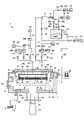
一実施形態に係る成膜装置について説明する。図1は、成膜装置の構成例を示す概略図である。図1に示される成膜装置は、原子層堆積(ALD:Atomic Layer Deposition)法によりタングステン膜を成膜できる装置である。(Deposition device)
A film forming apparatus according to one embodiment will be described. FIG. 1 is a schematic diagram showing a configuration example of a film forming apparatus. The film forming apparatus shown in FIG. 1 is an apparatus capable of forming a tungsten film by an atomic layer deposition (ALD) method.
図1に示されるように、成膜装置は、処理容器1と、載置台2と、シャワーヘッド3と、排気部4と、処理ガス供給機構5と、制御部6と、を有する。 As shown in FIG. 1 , the film forming apparatus has a
処理容器1は、アルミニウム等の金属により構成され、略円筒状を有する。処理容器1の側壁には、ウエハWを搬入又は搬出するための搬入出口11が形成されている。搬入出口11は、ゲートバルブ12により開閉される。処理容器1の本体の上には、断面が矩形状をなす円環状の排気ダクト13が設けられている。排気ダクト13には、内周面に沿ってスリット13aが形成されている。排気ダクト13の外壁には、排気口13bが形成されている。排気ダクト13の上面には、処理容器1の上部開口を塞ぐように天壁14が設けられている。排気ダクト13と天壁14との間はシールリング15で気密に封止されている。 The
載置台2は、処理容器1内で基板の一例である半導体ウエハ(以下「ウエハW」という。)を水平に支持する。載置台2は、ウエハWに対応した大きさの円板状をなし、支持部材23に支持されている。載置台2は、窒化アルミニウム(AlN)等のセラミックス材料や、アルミニウムやニッケル基合金等の金属材料で構成されている。載置台2の内部には、ウエハWを加熱するためのヒータ21が埋め込まれている。ヒータ21は、ヒータ電源(図示せず)から給電されて発熱する。そして、載置台2の上面のウエハ載置面近傍に設けられた熱電対(図示せず)の温度信号によりヒータ21の出力を制御することにより、ウエハWが所定の温度に制御される。 The mounting table 2 horizontally supports a semiconductor wafer (hereinafter referred to as “wafer W”), which is an example of a substrate, within the
載置台2には、ウエハ載置面の外周領域、及び載置台2の側面を覆うようにアルミナ等のセラミックスからなるカバー部材22が設けられている。 The mounting table 2 is provided with a
支持部材23は、載置台2の底面中央から処理容器1の底壁に形成された孔部を貫通して処理容器1の下方に延び、その下端が昇降機構24に接続されている。載置台2は、昇降機構24により支持部材23を介して、図1で示す処理位置と、その下方の二点鎖線で示すウエハの搬送が可能な搬送位置との間で昇降する。支持部材23の処理容器1の下方には、鍔部25が取り付けられている。処理容器1の底面と鍔部25との間には、処理容器1内の雰囲気を外気と区画し、載置台2の昇降動作にともなって伸縮するベローズ26が設けられている。 The
処理容器1の底面近傍には、昇降板27aから上方に突出するように3本(2本のみ図示)のウエハ支持ピン27が設けられている。ウエハ支持ピン27は、処理容器1の下方に設けられた昇降機構28により昇降板27aを介して昇降可能になっており、搬送位置にある載置台2に設けられた貫通孔2aに挿通されて載置台2の上面に対して突没可能となっている。このようにウエハ支持ピン27を昇降させることにより、ウエハ搬送機構(図示せず)と載置台2との間でウエハWの受け渡しが行われる。 Three wafer support pins 27 (only two are shown) are provided in the vicinity of the bottom surface of the
シャワーヘッド3は、処理容器1内に処理ガスをシャワー状に供給する。シャワーヘッド3は、金属により形成され、載置台2に対向するように設けられており、載置台2とほぼ同じ直径を有している。シャワーヘッド3は、処理容器1の天壁14に固定された本体部31と、本体部31の下に接続されたシャワープレート32と、を有する。本体部31とシャワープレート32との間にはガス拡散空間33が形成されている。ガス拡散空間33には、本体部31及び処理容器1の天壁14の中央を貫通するようにガス導入孔36が設けられている。シャワープレート32の周縁部には、下方に突出する環状突起部34が形成されている。シャワープレート32の環状突起部34の内側の平坦面には、ガス吐出孔35が形成されている。 The
載置台2が処理位置に存在した状態では、載置台2とシャワープレート32との間に処理空間37が形成され、載置台2のカバー部材22の上面と環状突起部34とが近接して環状隙間38が形成される。 When the mounting table 2 is in the processing position, a
排気部4は、処理容器1の内部を排気する。排気部4は、排気ダクト13の排気口13bに接続された排気配管41と、排気配管41に接続された排気機構42と、を有する。排気機構42は、真空ポンプや圧力制御バルブ等を有する。処理に際しては、処理容器1内のガスはスリット13aを介して排気ダクト13に至り、排気ダクト13から排気部4の排気機構42により排気配管41を通って排気される。 The exhaust unit 4 exhausts the inside of the
処理ガス供給機構5は、シャワーヘッド3に処理ガスを供給する。処理ガス供給機構5は、WCl6ガス供給機構G1、H2ガス供給源G2、第1のN2ガス供給源G3、及び第2のN2ガス供給源G4を有する。The processing
WCl6ガス供給機構G1は、処理容器1内に、WCl6ガス供給ラインL1を介して塩化タングステンガスの一例である六塩化タングステン(WCl6)ガスを供給する。WCl6ガス供給ラインL1は、WCl6ガス供給機構G1から延びるラインである。The WCl6 gas supply mechanism G1 supplies tungsten hexachloride (WCl6 ) gas, which is an example of tungsten chloride gas, into the
WCl6ガス供給ラインL1には、上流側から順に、開閉バルブ96a、開閉バルブ96b、流量計97、バッファタンクT1、及び開閉バルブV1が設けられている。開閉バルブ96a,96bは、WCl6ガス供給ラインL1の成膜原料タンク91の近傍に設けられている。流量計97は、WCl6ガス供給ラインL1を流れるWCl6ガスの流量を検出する。バッファタンクT1は、WCl6ガスを一時的に貯留し、短時間で必要なWCl6ガスを供給する。開閉バルブV1は、ALDの際にガスの供給及び停止を切り替えるためのバルブであり、例えば高速で開閉可能なALDバルブである。ALDバルブは、0.5秒以下の間隔で開閉可能であることが好ましく、0.01秒以下の間隔で開閉可能であることがより好ましい。The WCl6 gas supply line L1 is provided with an on-off valve 96a, an on-off
WCl6ガス供給機構G1は、常温で固体の固体原料であるWCl6を収容する原料容器である成膜原料タンク91を有する。成膜原料タンク91の周囲にはヒータ91aが設けられている。ヒータ91aは、成膜原料タンク91内の成膜原料を適宜の温度に加熱して、WCl6を昇華させる。成膜原料タンク91内には、WCl6ガス供給ラインL1が上方から挿入されている。The WCl6 gas supply mechanism G1 has a film-forming
また、WCl6ガス供給機構G1には、成膜原料タンク91内に上方からキャリアガス配管92の一端が挿入されている。キャリアガス配管92の他端は、キャリアN2ガス供給源93に接続されている。キャリアN2ガス供給源93は、キャリアガス配管92にキャリアガスの一例であるN2ガスを供給する。In addition, one end of a
キャリアガス配管92には、上流側から順に、マスフローコントローラ94、開閉バルブ95a、及び開閉バルブ95bが設けられている。マスフローコントローラ94は、キャリアガス配管92を流れるキャリアN2ガスの流量を制御する。The
キャリアガス配管92における開閉バルブ95aと開閉バルブ95bとの間の位置と、WCl6ガス供給ラインL1における開閉バルブ96aと開閉バルブ96bとの間の位置とを繋ぐように、バイパス配管98が設けられている。バイパス配管98は、キャリアN2ガス供給源93からキャリアガス配管92に供給されるキャリアN2ガスを、成膜原料タンク91を経由することなくWCl6ガス供給ラインL1に供給する配管である。バイパス配管98には、開閉バルブ99が介設されている。開閉バルブ95b,96aを閉じて開閉バルブ95a,99,96bを開くことにより、キャリアN2ガス供給源93から供給されるN2ガスがキャリアガス配管92、バイパス配管98を経て、WCl6ガス供給ラインL1に供給される。これにより、WCl6ガス供給ラインL1をパージできる。A
WCl6ガス供給ラインL1における流量計97の上流側には、希釈ガスであるN2ガスを供給する希釈N2ガス供給ライン100の下流側の端部が合流している。希釈N2ガス供給ライン100の上流側の端部には、N2ガスの供給源である希釈N2ガス供給源101が設けられている。希釈N2ガス供給ライン100には、上流側から順に、マスフローコントローラ102及び開閉バルブ103が介設されている。The upstream side of the
WCl6ガス供給ラインL1におけるバッファタンクT1と開閉バルブV1との間には、エバックライン104の一端が接続されている。エバックライン104は、処理容器1をバイパスしてWCl6ガス供給ラインL1と排気配管41とを接続する配管である。エバックライン104の他端は、排気配管41に接続されている。これにより、エバックライン104を介してバッファタンクT1内を排気機構42により排気できる。One end of the
エバックライン104には、上流側から順に、開閉バルブ105、オリフィス107、及び開閉バルブ106が介設されている。 An on-off
開閉バルブ105は、高速で開閉可能なALDバルブである。ALDバルブは、0.5秒以下の間隔で開閉可能であることが好ましく、0.01秒以下の間隔で開閉可能であることがより好ましい。開閉バルブ105の開閉動作により、成膜原料タンク91から供給されるWCl6ガスをエバックライン104に間欠的に供給できる。開閉バルブ105は、開閉バルブV1と同一又は略同一の速度で開閉可能なバルブであることが好ましい。これにより、成膜原料タンク91から開閉バルブV1を介して処理空間37に供給されるWCl6ガスと同様の周期で、エバックライン104にWCl6ガスを供給・排気できる。The open/
オリフィス107は、開閉バルブ105と開閉バルブ106との間に設けられている。オリフィス107は、エバックライン104内の圧力を、プロセス時の処理容器1内の圧力に近づけるために設けられている。 The
開閉バルブ106は、オリフィス107の下流側に設けられている。開閉バルブ106を開くことで、エバックライン104内が排気機構42により排気される。 The on-off
エバックライン104における開閉バルブ105の下流側、且つオリフィス107の上流側には、エバックライン104に圧力調整用ガスを供給する圧力調整用ガス供給ライン110の下流側の端部が合流している。圧力調整用ガス供給ライン110の上流側の端部には、圧力調整用ガスの供給源である圧力調整用ガス供給源111が設けられている。圧力調整用ガス供給ライン110には、上流側から順に、マスフローコントローラ112及び開閉バルブ113が介設されている。圧力調整用ガス供給源111から供給され、マスフローコントローラ112で流量が調整された圧力調整用ガスは、圧力調整用ガス供給ライン110を通ってエバックライン104に供給される。圧力調整用ガスは、例えばN2ガスであってよい。A downstream end of a pressure adjusting
H2ガス供給源G2は、処理容器1内に、H2ガス供給ラインL2を介して還元ガスの一例であるH2ガスを供給する。H2ガス供給ラインL2は、H2ガス供給源G2から延びるラインである。WCl6ガス供給ラインL1及びH2ガス供給ラインL2は、合流配管L0に合流しており、合流配管L0は、前述したガス導入孔36に接続されている。H2ガス供給ラインL2には、上流側から順に、マスフローコントローラM2、バッファタンクT2、開閉バルブV2が設けられている。マスフローコントローラM2は、H2ガス供給ラインL2を流れるH2ガスの流量を制御する。バッファタンクT2は、H2ガスを一時的に貯留し、短時間で必要なH2ガスを供給する。開閉バルブV2は、ALDの際にガスの供給及び停止を切り替えるためのバルブであり、例えば高速で開閉可能なALDバルブである。ALDバルブは、0.01秒から1.0秒の間隔で開閉可能であることが好ましい。The H2 gas supply source G2 supplies H2 gas, which is an example of a reducing gas, into the
第1のN2ガス供給源G3は、処理容器1内に、第1のN2ガス供給ラインL3を介してパージガスの一例であるN2ガスを供給する。第1のN2ガス供給ラインL3は、第1のN2ガス供給源G3から延び、WCl6ガス供給ラインL1側にN2ガスを供給するラインである。第1のN2ガス供給ラインL3は、ALD法による成膜中に常にN2ガスを供給する第1の連続N2ガス供給ラインL31と、パージステップのときのみN2ガスを供給する第1のフラッシュパージラインL32とに分岐している。第1の連続N2ガス供給ラインL31及び第1のフラッシュパージラインL32は第1の接続ラインL33に接続され、第1の接続ラインL33はWCl6ガス供給ラインL1に接続されている。第1の連続N2ガス供給ラインL31には、上流側から順に、マスフローコントローラM31、開閉バルブV31が設けられている。第1のフラッシュパージラインL32には、上流側から順に、マスフローコントローラM32、開閉バルブV32が設けられている。マスフローコントローラM31,M32は、それぞれ第1の連続N2ガス供給ラインL31及び第1のフラッシュパージラインL32を流れるN2ガスの流量を制御する。開閉バルブV31及び開閉バルブV32は、ALDの際にガスの供給及び停止を切り替えるためのバルブであり、例えば高速で開閉可能なALDバルブである。ALDバルブは、0.01秒から1.0秒の間隔で開閉可能であることが好ましい。A firstN2 gas supply source G3 suppliesN2 gas, which is an example of a purge gas, into the
第2のN2ガス供給源G4は、処理容器1内に、第2のN2ガス供給ラインL4を介してパージガスの一例であるN2ガスを供給する。第2のN2ガス供給ラインL4は、第2のN2ガス供給源G4から延び、H2ガス供給ラインL2側にN2ガスを供給するラインである。第2のN2ガス供給ラインL4は、ALD法による成膜中に常にN2ガスを供給する第2の連続N2ガス供給ラインL41と、パージステップのときのみN2ガスを供給する第2のフラッシュパージラインL42とに分岐している。第2の連続N2ガス供給ラインL41、及び第2のフラッシュパージラインL42は第2の接続ラインL43に接続され、第2の接続ラインL43はH2ガス供給ラインL2に接続されている。第2の連続N2ガス供給ラインL41には、上流側から順に、マスフローコントローラM41、開閉バルブV41が設けられている。第2のフラッシュパージラインL42には、上流側から順に、マスフローコントローラM42、開閉バルブV42が設けられている。マスフローコントローラM41,M42は、それぞれ第2の連続N2ガス供給ラインL41及び第2のフラッシュパージラインL42を流れるN2ガスの流量を制御する。開閉バルブV41及び開閉バルブV42は、ALDの際にガスの供給及び停止を切り替えるためのバルブであり、例えば高速で開閉可能なALDバルブである。ALDバルブは、0.01秒から1.0秒の間隔で開閉可能であることが好ましい。A secondN2 gas supply source G4 supplies N2 gas, which is an example of a purge gas, into the
制御部6は、成膜装置の各部の動作を制御する。制御部6は、例えばコンピュータであってよい。成膜装置の各部の動作を行うコンピュータのプログラムは、記憶媒体に記憶されている。記憶媒体は、例えばフレキシブルディスク、コンパクトディスク、ハードディスク、フラッシュメモリ、DVD等であってよい。 A control unit 6 controls the operation of each unit of the film forming apparatus. The control unit 6 may be, for example, a computer. A computer program for operating each part of the film forming apparatus is stored in a storage medium. The storage medium may be, for example, a flexible disk, compact disk, hard disk, flash memory, DVD, or the like.
(成膜方法)
一実施形態に係る成膜方法について、図1の成膜装置を用いてタングステン膜を成膜する場合を例に挙げて説明する。一実施形態に係る成膜方法は、制御部6が成膜装置の各部の動作を制御することにより実行される。図2は、成膜方法の一例を示すフローチャートである。(Film formation method)
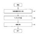
A film forming method according to an embodiment will be described by taking as an example the case of forming a tungsten film using the film forming apparatus shown in FIG. A film forming method according to one embodiment is executed by the control unit 6 controlling the operation of each part of the film forming apparatus. FIG. 2 is a flow chart showing an example of a film forming method.
図2に示されるように、一実施形態に係る成膜方法は、初期流量安定化工程S1、エッチング工程S2、及び成膜工程S3をこの順序で行うことにより、基板の表面に形成された下地膜の上にタングステン膜を成膜する方法である。但し、初期流量安定化工程S1は省略してもよい。 As shown in FIG. 2, the film formation method according to one embodiment performs an initial flow rate stabilization step S1, an etching step S2, and a film formation step S3 in this order, thereby forming a lower layer on the surface of the substrate. This is a method of forming a tungsten film on a base film. However, the initial flow rate stabilization step S1 may be omitted.
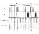
以下、各工程について説明する。図3は、エッチング工程S2及び成膜工程S3のガス供給シーケンスの一例を示す図である。図4は、成膜方法の一例を示す工程断面図である。図4(a)はエッチング工程S2前の基板の断面を示し、図4(b)はエッチング工程S2後の基板の断面を示し、図4(c)は成膜工程S3後の基板の断面を示す。なお、以下では、開閉バルブV1,V2,V31,V32,V41,V42が閉じている状態から一実施形態に係る成膜方法を実施する場合を一例として説明する。 Each step will be described below. FIG. 3 is a diagram showing an example of the gas supply sequence of the etching step S2 and the film forming step S3. FIG. 4 is a process cross-sectional view showing an example of a film forming method. 4(a) shows a cross section of the substrate before the etching step S2, FIG. 4(b) shows a cross section of the substrate after the etching step S2, and FIG. 4(c) shows a cross section of the substrate after the film forming step S3. show. In addition, below, the case where the film-forming method which concerns on one Embodiment is implemented from the state which the opening-and-closing valves V1, V2, V31, V32, V41, and V42 are closed is demonstrated as an example.
まず、載置台2を搬送位置に下降させた状態でゲートバルブ12を開き、搬送装置(図示せず)によりウエハWを、搬入出口11を介して処理容器1内に搬入し、ヒータ21により所定温度(例えば、350℃~550℃)に加熱された載置台2上に載置する。続いて、載置台2を処理位置まで上昇させ、処理容器1内を所定圧力まで減圧する。その後、開閉バルブV31,V41を開く。これにより、第1のN2ガス供給源G3及び第2のN2ガス供給源G4から、第1の連続N2ガス供給ラインL31及び第2の連続N2ガス供給ラインL41を経てN2ガスを処理容器1内に供給して圧力を上昇させ、載置台2上のウエハWの温度を安定させる。ウエハWとしては、例えば図4(a)に示されるように、凹部501aを有するシリコン膜501の表面に下地膜502が形成されたものを利用できる。但し、シリコン膜501に代えてシリコン酸化膜であってもよい。下地膜502としては、TiN膜、TiSiN膜、Tiシリサイド膜、Ti膜、TiO2膜、TiAlN膜等のチタン系材料膜、TaN、TaSiN等のタンタル系材料膜、WN膜、WSix膜、WSiN膜等のタングステン系化合物膜が挙げられる。下地膜502は同じ真空搬送系を介した別の装置で成膜処理されてもよい。また、下地膜502はエッチング工程S2と同一の処理容器1内でエッチング工程S2に先立って成膜処理されてもよい。このように下地膜502を成膜処理した後、下地膜502を大気に曝露することなくエッチング工程S2を行うことにより、下地膜502の表面の酸化が防止され、エッチング工程S2において下地膜502のエッチング速度にばらつきが生じることを抑制できる。なお、下地膜502の膜厚は1Åから50Å程度である。First, with the mounting table 2 lowered to the transfer position, the
続いて、初期流量安定化工程S1を実行する。初期流量安定化工程S1は、エバックライン104にWCl6ガスを間欠的に供給する工程であり、処理容器1内にウエハWが搬入された後に実行される。Subsequently, an initial flow rate stabilization step S1 is performed. The initial flow rate stabilization step S<b>1 is a step of intermittently supplying WCl6 gas to the
初期流量安定化工程S1では、まず、WCl6ガス供給ラインL1にWCl6ガスを供給し、バッファタンクT1内にWCl6ガスを充填させる。具体的には、開閉バルブV1,105を閉じた状態で、開閉バルブ95a,95b,96a,96bを開くことにより、キャリアN2ガス供給源93及び成膜原料タンク91からWCl6ガス供給ラインL1にそれぞれN2ガス及びWCl6ガスを供給する。また、開閉バルブ103を開くことにより、希釈N2ガス供給ライン100からWCl6ガス供給ラインL1にN2ガスを供給する。WCl6ガス供給ラインL1に供給されたWCl6ガス及びN2ガスは、バッファタンクT1内に充填される。In the initial flow rate stabilization step S1, first, theWCl6 gas is supplied to theWCl6 gas supply line L1 to fill the buffer tank T1 with theWCl6 gas. Specifically, by opening the on-off
バッファタンクT1内にWCl6ガス及びN2ガスが充填された後、エバックライン104にWCl6ガス及びN2ガスを間欠的に供給する。具体的には、開閉バルブV1を閉じた状態で開閉バルブ105を高速で開閉動作させることにより、エバックライン104にWCl6ガス及びN2ガスを間欠的に供給する。また、開閉バルブ106を開き、エバックライン104に供給されるWCl6ガス及びN2ガスを、オリフィス107を介して排気機構42により排気する。これにより、エッチング工程S2に先立って、処理容器1内にWCl6ガス及びN2ガスを供給することなく、エッチング工程S2と略同等のガス供給環境を実現できるので、エッチング工程S2の開始時におけるWCl6ガスの流量が短時間で安定化する。開閉バルブ105の開閉タイミングは、エッチング工程S2における開閉バルブV1の開閉タイミングと同一又は略同一であることが好ましい。これにより、エッチング工程S2におけるガス供給環境を高い精度で実現できる。After the buffer tank T1 is filled with the WCl6 gas and the N2 gas, the
また、初期流量安定化工程S1では、エバックライン104内の圧力を成膜中の処理空間37の圧力により近づけるために、開閉バルブ113を開いて圧力調整用ガス供給源111からエバックライン104に圧力調整用ガスを供給することが好ましい。このとき、マスフローコントローラ112により、エバックライン104内の圧力が成膜中の処理空間37の圧力と略同一となるように、エバックライン104に供給する圧力調整用ガスの流量を調整することが好ましい。 Further, in the initial flow rate stabilization step S1, in order to bring the pressure in the
続いて、エッチング工程S2を実行する。エッチング工程S2は、ウエハWが収容された処理容器1内に塩化タングステンガスの一例であるWCl6ガスをパージを挟んで間欠的に供給することで、下地膜の一部をエッチングして下地膜の膜厚を減ずる工程である。エッチング工程S2では、図3に示されるように、第1ステップS21~第4ステップS24を順番に行う一連の動作を所定の回数繰り返すことで、図4(b)に示されるように、下地膜502の一部をエッチングして下地膜502を所定の膜厚に薄膜化する。所定の回数は、例えば予め定められたエッチング工程のサイクル数と下地膜のエッチング量との関係を示す関係情報に基づいて定められる。関係情報は、例えば図6に示されるようにエッチング工程のサイクル数と下地膜のエッチング量との関係を示すグラフであってよい。また、関係情報は、例えばテーブル、数式等であってもよい。これらの関係情報は、例えば予備実験の結果に基づいて生成される。一実施形態では、所定の回数は1回~100回であり、所定の膜厚は1Å~40Åである。エッチング工程S2の第1ステップS21~第4ステップS24は、還元ガスを供給しない点を除いて、それぞれ後述する成膜工程S3の第1ステップS31~第4ステップS34と同様であってよい。Then, etching process S2 is performed. In the etching step S2, by intermittently supplying WCl6 gas, which is an example of a tungsten chloride gas, into the
第1ステップS21は、原料ガスであるWCl6ガスを処理空間37に供給するステップである。第1ステップS21では、開閉バルブV31,V41を開いた状態で、第1のN2ガス供給源G3及び第2のN2ガス供給源G4から第1の連続N2ガス供給ラインL31及び第2の連続N2ガス供給ラインL41を経てN2ガス(連続パージN2ガス)を供給する。一実施形態では、連続パージN2ガスの合計の流量は200sccm~5000sccmである。また、開閉バルブV1を開くことにより、WCl6ガス供給機構G1からWCl6ガス供給ラインL1を経てWCl6ガスを処理空間37に供給する。このとき、バッファタンクT1に一旦貯留され、初期流量安定化工程S1により安定化された流量のWCl6ガスが供給される。一実施形態では、WCl6ガスの流量は10mg/min~200mg/minである。The first step S<b>21 is a step of supplying WCl6 gas, which is a raw material gas, to the
第2ステップS22は、処理空間37の余剰のWCl6ガス等をパージするステップである。第2ステップS22では、第1の連続N2ガス供給ラインL31及び第2の連続N2ガス供給ラインL41を介してのN2ガスの供給を継続した状態で、開閉バルブV1を閉じてWCl6ガスの供給を停止する。また、開閉バルブV32,V42を開くことにより、第1のフラッシュパージラインL32及び第2のフラッシュパージラインL42からもN2ガス(フラッシュパージN2ガス)を供給する。これにより、大流量のN2ガスにより、処理空間37の余剰のWCl6ガス等をパージする。The second step S22 is a step of purging excess WCl6 gas and the like in the
第3ステップS23は、連続パージN2ガスのみを処理空間37に供給するステップである。第3ステップS23では、開閉バルブV32,V42を閉じて第1のフラッシュパージラインL32及び第2のフラッシュパージラインL42からのN2ガスの供給を停止する。一方、第1の連続N2ガス供給ラインL31及び第2の連続N2ガス供給ラインL41を介してのN2ガスの供給を継続する。A third step S23 is a step of supplying only the continuous purgeN2 gas to the
第4ステップS24は、処理空間37をパージするステップである。第4ステップS24では、第1の連続N2ガス供給ラインL31及び第2の連続N2ガス供給ラインL41を介してのN2ガスの供給を継続した状態で、開閉バルブV32,V42を開く。これにより、第1のフラッシュパージラインL32及び第2のフラッシュパージラインL42からN2ガス(フラッシュパージN2ガス)を供給し、大流量のN2ガスにより、処理空間37をパージする。A fourth step S24 is a step of purging the
続いて、成膜工程S3を実行する。成膜工程S3は、処理容器1内にWCl6ガスとWCl6ガスを還元する還元ガスの一例であるH2ガスとをパージを挟んで交互に供給することで、下地膜の上にタングステン膜を成膜する工程である。成膜工程S3では、図3に示されるように、第1ステップS31~第4ステップS34を順番に行う一連の動作を所定の回数繰り返す。これにより、図4(c)に示されるように、エッチング工程S2において薄膜化された下地膜502の上に所望の膜厚のタングステン膜503を成膜する。一実施形態では、所定の回数は20回~200回である。Then, film-forming process S3 is performed. In the film forming step S3, a WCl6 gas and an H2 gas, which is an example of a reducing gas for reducing the WCl6 gas, are alternately supplied into the
第1ステップS31は、原料ガスであるWCl6ガスを処理空間37に供給するステップである。第1ステップS31では、開閉バルブV31,V41を開いた状態で、第1のN2ガス供給源G3及び第2のN2ガス供給源G4から第1の連続N2ガス供給ラインL31及び第2の連続N2ガス供給ラインL41を経てN2ガス(連続パージN2ガス)を供給する。一実施形態では、連続パージN2ガスの合計の流量は200sccm~5000sccmである。また、開閉バルブV1を開くことにより、WCl6ガス供給機構G1からWCl6ガス供給ラインL1を経てWCl6ガスを処理空間37に供給する。このとき、バッファタンクT1に一旦貯留されたWCl6ガスが供給される。一実施形態では、WCl6ガスの流量は10mg/min~200mg/minである。The first step S<b>31 is a step of supplying WCl6 gas, which is a raw material gas, to the
第2ステップS32は、処理空間37の余剰のWCl6ガス等をパージするステップである。第2ステップS32では、第1の連続N2ガス供給ラインL31及び第2の連続N2ガス供給ラインL41を介してのN2ガスの供給を継続した状態で、開閉バルブV1を閉じてWCl6ガスの供給を停止する。また、開閉バルブV32,V42を開くことにより、第1のフラッシュパージラインL32及び第2のフラッシュパージラインL42からもN2ガス(フラッシュパージN2ガス)を供給する。これにより、大流量のN2ガスにより、処理空間37の余剰のWCl6ガス等をパージする。The second step S32 is a step of purging excess WCl6 gas and the like in the
第3ステップS33は、還元ガスであるH2ガスを処理空間37に供給するステップである。第3ステップS33では、開閉バルブV32,V42を閉じて第1のフラッシュパージラインL32及び第2のフラッシュパージラインL42からのN2ガスの供給を停止する。また、第1の連続N2ガス供給ラインL31及び第2の連続N2ガス供給ラインL41を介してのN2ガスの供給を継続した状態で、開閉バルブV2を開く。これにより、H2ガス供給源G2からH2ガス供給ラインL2を経て還元ガスの一例であるH2ガスを処理空間37に供給する。このとき、H2ガスは、バッファタンクT2に一旦貯留された後に処理容器1内に供給される。第3ステップS33により、ウエハW上に吸着したWCl6ガスが還元される。このときのH2ガスの流量は、十分に還元反応が生じる量とすることができる。A third step S<b>33 is a step of supplying H2 gas, which is a reducing gas, to the
第4ステップS34は、処理空間37の余剰のH2ガスをパージするステップである。第4ステップS34では、第1の連続N2ガス供給ラインL31及び第2の連続N2ガス供給ラインL41を介してのN2ガスの供給を継続した状態で、開閉バルブV2を閉じてH2ガス供給ラインL2からのH2ガスの供給を停止する。また、開閉バルブV32,V42を開き、第1のフラッシュパージラインL32及び第2のフラッシュパージラインL42からもN2ガス(フラッシュパージN2ガス)を供給し、大流量のN2ガスにより、処理空間37の余剰のH2ガスをパージする。A fourth step S<b>34 is a step of purging excess H2 gas in the
以上に説明したように、一実施形態に係る成膜方法によれば、凹部501aを有するシリコン膜501の表面に連続膜である下地膜502が形成されたウエハWに対し、エッチング工程S2及び成膜工程S3をこの順序で行う。これにより、エッチング工程S2において下地膜502を所定の膜厚(例えば1Å~40Å)に薄膜化しても連続膜の状態が維持される。そのため、成膜工程S3においてタングステン膜503をシリコン膜501へダメージを与えることなく、また、良好な密着性で成膜できる。また、凹部501a内の下地膜502を薄膜化することで、凹部に埋め込まれるタングステン膜の割合を高めることができる。その結果、凹部501aに埋め込まれるタングステン膜の抵抗を小さくできる。 As described above, according to the film formation method according to one embodiment, the wafer W having the
ところで、凹部501aを有するシリコン膜501の表面に初めから膜厚が薄い下地膜502を成膜することも考えられる。しかし、この場合、図5に示されるように、下地膜502が島状に形成されて不連続膜になる。そのため、成膜工程S3においてタングステン膜503をシリコン膜501へダメージを与えることなく、また、良好な密着性で成膜することが困難である。なお、図5は、従来の成膜方法の説明図である。 By the way, it is conceivable to form a
また、一実施形態に係る成膜方法によれば、エッチング工程S2と成膜工程S3とが同一の処理容器内で連続して行われる。これにより、下地膜502の表面が酸化されることを防止できるので、成膜工程S3においてタングステン膜503をより酸素を含まない低抵抗、かつ、良好な密着性で成膜できる。 Moreover, according to the film forming method according to one embodiment, the etching step S2 and the film forming step S3 are continuously performed in the same processing container. As a result, the surface of the
また、一実施形態に係る成膜方法によれば、エッチング工程S2の第1ステップS21~第4ステップS24は、還元ガスを供給しない点を除いて、それぞれ成膜工程S3の第1ステップS31~第4ステップS34と同様である。これにより、エッチング工程S2と成膜工程S3の切り替えに伴う固体原料の不安定化を発生させることなく、安定供給が可能となる。 Further, according to the film forming method according to one embodiment, the first step S21 to the fourth step S24 of the etching step S2 are the first steps S31 to S31 of the film forming step S3, respectively, except that the reducing gas is not supplied. It is the same as the fourth step S34. As a result, stable supply is possible without destabilizing the solid raw material due to switching between the etching process S2 and the film forming process S3.
今回開示された実施形態はすべての点で例示であって制限的なものではないと考えられるべきである。上記の実施形態は、添付の請求の範囲及びその趣旨を逸脱することなく、様々な形態で省略、置換、変更されてもよい。 It should be considered that the embodiments disclosed this time are illustrative in all respects and not restrictive. The above-described embodiments may be omitted, substituted or modified in various ways without departing from the scope and spirit of the appended claims.
上記の実施形態では、塩化タングステンガスとしてWCl6ガスを用いる場合を例に挙げて説明したが、これに限定されず、例えば五塩化タングステン(WCl5)ガスを用いることもでき、WCl5ガスを用いてもWCl6ガスとほぼ同じ挙動を示す。WCl5ガスを用いる場合、成膜原料としては常温で固体のWCl5を利用できる。In the above embodiment, the case whereWCl6 gas is used as the tungsten chloride gas has been described as an example, but the present invention is not limited to this. It exhibits almost the same behavior as WCl6 gas even when used. When WCl5 gas is used, WCl5 , which is solid at room temperature, can be used as a film forming material.
また、上記の実施形態では、還元ガスとしてH2ガスを用いる場合を例に挙げて説明したが、水素を含む還元性のガスであればよく、H2ガスの他に、SiH4ガス、B2H6ガス、NH3ガス等を用いることもできる。H2ガス、SiH4ガス、B2H6ガス、及びNH3ガスのうち2つ以上を供給できるようにしてもよい。また、これら以外の他の還元ガス、例えばPH3ガス、SiH2Cl2ガスを用いてもよい。膜中の不純物をより低減して低抵抗値を得る観点からは、H2ガスを用いることが好ましい。さらに、パージガス及びキャリアガスとしてN2ガスの代わりにArガス等の他の不活性ガスを用いることもできる。Further, in the above embodiment, the case of using H2 gas as a reducing gas has been described as an example, but any reducing gas containing hydrogen may be used. Besides H2 gas, SiH4 gas, B2H6 gas,NH3 gas, etc. can also be used.Two or more of H2 gas,SiH4 gas,B2H6 gas, andNH3 gas may be supplied. Other reducing gases other than these, such as PH3 gas and SiH2 Cl2 gas, may also be used. From the viewpoint of further reducing impurities in the film and obtaining a low resistance value, it is preferable to use H2 gas. Furthermore, other inert gases such as Ar gas can be used as purge gas and carrier gas instead ofN2 gas.
また、上記の実施形態では、基板として半導体ウエハを例に挙げて説明したが、半導体ウエハはシリコンウエハであってもよく、GaAs、SiC、GaN等の化合物半導体ウエハであってもよい。さらに、基板は半導体ウエハに限定されず、液晶表示装置等のFPD(フラットパネルディスプレイ)に用いるガラス基板や、セラミック基板等であってもよい。 Further, in the above embodiments, a semiconductor wafer is used as an example of the substrate, but the semiconductor wafer may be a silicon wafer or a compound semiconductor wafer such as GaAs, SiC, or GaN. Furthermore, the substrate is not limited to a semiconductor wafer, and may be a glass substrate used for an FPD (flat panel display) such as a liquid crystal display device, a ceramic substrate, or the like.
1 処理容器
4 排気部
5 処理ガス供給機構
6 制御部
41 排気配管
104 エバックライン
501 シリコン膜
501a 凹部
502 下地膜
503 タングステン膜
G1 WCl6ガス供給機構
G2 H2ガス供給源1 processing container 4
Claims (8)
Translated fromJapanese前記エッチング工程の後、前記処理容器内に前記塩化タングステンガスと前記塩化タングステンガスを還元する還元ガスとをパージを挟んで交互に供給することで、前記下地膜の上にタングステン膜を成膜する成膜工程と、
を有し、
前記下地膜は、前記タングステン膜とは異なる金属を含む膜からなり、
前記エッチング工程後の前記下地膜の膜厚は1Å~40Åである、
成膜方法。By intermittently supplying a tungsten chloride gas with a purge interposed in a processing container in which a substratehaving a concave portion on the surface and having an underlying filmformed thereon so as to cover the concave portion is accommodated, a portion of the underlying film is removed. an etching step of etching to reduce the film thickness of the underlying film;
After the etching step, the tungsten chloride gas and a reducing gas for reducing the tungsten chloride gas are alternately supplied into the processing chamber with a purge interposed therebetween, thereby forming a tungsten film on the base film. a film forming process;
has
the base film is made of a film containing a metal different from the tungsten film,
The film thickness of the base film after the etching step is 1 Å to 40 Å,
Deposition method.
請求項1に記載の成膜方法。The etching step and the film forming step are continuously performed in the same processing container,
The film forming method according to claim 1 .
前記処理容器内に前記塩化タングステンガスを供給する第1ステップと、
前記処理容器内にパージガスを供給する第2ステップと、
前記処理容器内に前記還元ガスを供給する第3ステップと、
前記処理容器内にパージガスを供給する第4ステップと、
をこの順序で繰り返す工程であり、
前記エッチング工程は、
前記成膜工程の前記第3ステップにおいて前記還元ガスを供給することなく、前記第1ステップ、前記第2ステップ、前記第3ステップ、及び前記第4ステップをこの順序で繰り返す工程である、
請求項1又は2に記載の成膜方法。The film forming step includes
a first step of supplying the tungsten chloride gas into the processing container;
a second step of supplying a purge gas into the processing vessel;
a third step of supplying the reducing gas into the processing container;
a fourth step of supplying a purge gas into the processing container;
is repeated in this order,
The etching step includes
A step of repeating the first step, the second step, the third step, and the fourth step in this order without supplying the reducing gas in the third step of the film formation step,
The film forming method according to claim 1 or 2.
請求項1乃至3のいずれか一項に記載の成膜方法。An initial flow stabilization step of supplying and exhausting the tungsten chloride gas to an evacuation line connected to an exhaust pipe bypassing the processing container, which is performed before the etching step;
The film forming method according to any one of claims 1 to 3.
請求項4に記載の成膜方法。In the initial flow rate stabilization step, the tungsten chloride gas is intermittently supplied at the same or substantially the same period as the etching step,
The film forming method according to claim 4 .
前記下地膜は少なくとも前記凹部内に形成されており、
前記成膜工程では、前記凹部内に前記タングステン膜を成膜して前記凹部を埋め込む、
請求項1乃至5のいずれか一項に記載の成膜方法。A concave portion is formed on the surface of the substrate,
The base film is formed at least within the recess,
In the film formation step, the tungsten film is formed in the recess to fill the recess.
The film forming method according to any one of claims 1 to 5.
前記塩化タングステンガスは、WCl6を昇華させて生成したガスであり、
前記還元ガスは、H2ガスである、
請求項1乃至6のいずれか一項に記載の成膜方法。The underlying film is a TiN film,
The tungsten chloride gas is a gas generated by sublimatingWCl6 ,
The reducing gas is H2 gas,
The film forming method according to any one of claims 1 to 6.
前記処理容器内に塩化タングステンガス及び前記塩化タングステンガスを還元する還元ガスを供給する処理ガス供給機構と、
制御部と、
を有し、
前記制御部は、
前記処理容器内に塩化タングステンガスをパージを挟んで間欠的に供給することで、前記下地膜の一部をエッチングして前記下地膜の膜厚を減ずるエッチング工程と、
前記処理容器内に前記塩化タングステンガスと前記塩化タングステンガスを還元する還元ガスとをパージを挟んで交互に供給することで、前記下地膜の上にタングステン膜を成膜する成膜工程と、
をこの順序で実行するように構成され、
前記下地膜は、前記タングステン膜とは異なる金属を含む膜からなり、
前記エッチング工程後の前記下地膜の膜厚は1Å~40Åである、
成膜装置。a processing container for accommodating a substratehaving a recess on its surface and having a base filmformed thereon so as to cover the recess;
a processing gas supply mechanism that supplies a tungsten chloride gas and a reducing gas that reduces the tungsten chloride gas into the processing container;
a control unit;
has
The control unit
an etching step of intermittently supplying a tungsten chloride gas into the processing chamber with a purge interposed therebetween to etch a portion of the underlying film to reduce the film thickness of the underlying film;
a film forming step of forming a tungsten film on the base film by alternately supplying the tungsten chloride gas and a reducing gas for reducing the tungsten chloride gas into the processing container with a purge interposed therebetween;
areconfigured to run in that order, and
the base film is made of a film containing a metal different from the tungsten film,
The film thickness of the base film after the etching step is 1 Å to 40 Å,
Deposition equipment.
Priority Applications (3)
| Application Number | Priority Date | Filing Date | Title |
|---|---|---|---|
| JP2018177532AJP7149788B2 (en) | 2018-09-21 | 2018-09-21 | Film forming method and film forming apparatus |
| US16/574,757US10872814B2 (en) | 2018-09-21 | 2019-09-18 | Film forming method and film forming apparatus |
| KR1020190114494AKR102294791B1 (en) | 2018-09-21 | 2019-09-18 | Film forming method and film forming apparatus |
Applications Claiming Priority (1)
| Application Number | Priority Date | Filing Date | Title |
|---|---|---|---|
| JP2018177532AJP7149788B2 (en) | 2018-09-21 | 2018-09-21 | Film forming method and film forming apparatus |
Publications (2)
| Publication Number | Publication Date |
|---|---|
| JP2020045548A JP2020045548A (en) | 2020-03-26 |
| JP7149788B2true JP7149788B2 (en) | 2022-10-07 |
Family
ID=69883593
Family Applications (1)
| Application Number | Title | Priority Date | Filing Date |
|---|---|---|---|
| JP2018177532AActiveJP7149788B2 (en) | 2018-09-21 | 2018-09-21 | Film forming method and film forming apparatus |
Country Status (3)
| Country | Link |
|---|---|
| US (1) | US10872814B2 (en) |
| JP (1) | JP7149788B2 (en) |
| KR (1) | KR102294791B1 (en) |
Families Citing this family (4)
| Publication number | Priority date | Publication date | Assignee | Title |
|---|---|---|---|---|
| WO2021053778A1 (en)* | 2019-09-19 | 2021-03-25 | 株式会社Kokusai Electric | Method for manufacturing semiconductor device, recording medium, and substrate processing device |
| CN112614855A (en)* | 2020-12-07 | 2021-04-06 | 长江存储科技有限责任公司 | Preparation method of semiconductor etched hole inner film layer and three-dimensional memory structure |
| KR20240002074A (en) | 2022-06-28 | 2024-01-04 | 삼성전자주식회사 | Method of depositing atomic layer and method of manufacturing Semiconductor device |
| JP2025062309A (en)* | 2023-10-02 | 2025-04-14 | 東京エレクトロン株式会社 | Film formation method and semiconductor manufacturing apparatus |
Citations (4)
| Publication number | Priority date | Publication date | Assignee | Title |
|---|---|---|---|---|
| JP2009026864A (en) | 2007-07-18 | 2009-02-05 | Toshiba Corp | Semiconductor device manufacturing method and semiconductor device |
| JP2013032575A (en) | 2011-07-06 | 2013-02-14 | Tokyo Electron Ltd | Method for depositing tungsten film |
| WO2015080058A1 (en) | 2013-11-27 | 2015-06-04 | 東京エレクトロン株式会社 | Method for forming tungsten film |
| JP2015190020A (en) | 2014-03-28 | 2015-11-02 | 東京エレクトロン株式会社 | Method for forming tungsten film |
Family Cites Families (16)
| Publication number | Priority date | Publication date | Assignee | Title |
|---|---|---|---|---|
| US9230815B2 (en)* | 2012-10-26 | 2016-01-05 | Appled Materials, Inc. | Methods for depositing fluorine/carbon-free conformal tungsten |
| JP6494940B2 (en)* | 2013-07-25 | 2019-04-03 | ラム リサーチ コーポレーションLam Research Corporation | Void-free tungsten filling to different size features |
| JP6437324B2 (en)* | 2014-03-25 | 2018-12-12 | 東京エレクトロン株式会社 | Method for forming tungsten film and method for manufacturing semiconductor device |
| US20150348840A1 (en)* | 2014-05-31 | 2015-12-03 | Lam Research Corporation | Methods of filling high aspect ratio features with fluorine free tungsten |
| JP6391355B2 (en)* | 2014-08-11 | 2018-09-19 | 東京エレクトロン株式会社 | Method for forming tungsten film |
| JP6706903B2 (en)* | 2015-01-30 | 2020-06-10 | 東京エレクトロン株式会社 | Method for forming tungsten film |
| JP6416679B2 (en)* | 2015-03-27 | 2018-10-31 | 東京エレクトロン株式会社 | Method for forming tungsten film |
| US9978605B2 (en)* | 2015-05-27 | 2018-05-22 | Lam Research Corporation | Method of forming low resistivity fluorine free tungsten film without nucleation |
| JP6541438B2 (en)* | 2015-05-28 | 2019-07-10 | 東京エレクトロン株式会社 | Method of reducing stress of metal film and method of forming metal film |
| JP6710089B2 (en)* | 2016-04-04 | 2020-06-17 | 東京エレクトロン株式会社 | Method for forming tungsten film |
| JP6948803B2 (en)* | 2017-03-02 | 2021-10-13 | 東京エレクトロン株式会社 | Gas supply device, gas supply method and film formation method |
| JP6964473B2 (en)* | 2017-09-14 | 2021-11-10 | 東京エレクトロン株式会社 | Gas supply equipment and film formation equipment |
| JP7085824B2 (en)* | 2017-11-28 | 2022-06-17 | 東京エレクトロン株式会社 | Film formation method |
| JP7018748B2 (en)* | 2017-11-28 | 2022-02-14 | 東京エレクトロン株式会社 | Film formation method and calculation method of film formation conditions |
| JP7233188B2 (en)* | 2018-09-20 | 2023-03-06 | 東京エレクトロン株式会社 | Film forming method and film forming apparatus |
| JP7362258B2 (en)* | 2019-02-08 | 2023-10-17 | 東京エレクトロン株式会社 | Substrate processing method and film formation system |
- 2018
- 2018-09-21JPJP2018177532Apatent/JP7149788B2/enactiveActive
- 2019
- 2019-09-18USUS16/574,757patent/US10872814B2/enactiveActive
- 2019-09-18KRKR1020190114494Apatent/KR102294791B1/enactiveActive
Patent Citations (4)
| Publication number | Priority date | Publication date | Assignee | Title |
|---|---|---|---|---|
| JP2009026864A (en) | 2007-07-18 | 2009-02-05 | Toshiba Corp | Semiconductor device manufacturing method and semiconductor device |
| JP2013032575A (en) | 2011-07-06 | 2013-02-14 | Tokyo Electron Ltd | Method for depositing tungsten film |
| WO2015080058A1 (en) | 2013-11-27 | 2015-06-04 | 東京エレクトロン株式会社 | Method for forming tungsten film |
| JP2015190020A (en) | 2014-03-28 | 2015-11-02 | 東京エレクトロン株式会社 | Method for forming tungsten film |
Also Published As
| Publication number | Publication date |
|---|---|
| KR102294791B1 (en) | 2021-08-26 |
| US10872814B2 (en) | 2020-12-22 |
| KR20200034611A (en) | 2020-03-31 |
| JP2020045548A (en) | 2020-03-26 |
| US20200098624A1 (en) | 2020-03-26 |
Similar Documents
| Publication | Publication Date | Title |
|---|---|---|
| JP6416679B2 (en) | Method for forming tungsten film | |
| US10870919B2 (en) | Gas supply method and film forming method | |
| KR101912995B1 (en) | Method of reducing stress in metal film and metal film forming method | |
| KR101892344B1 (en) | Method of forming metal film | |
| US10400330B2 (en) | Tungsten film forming method and storage medium | |
| JP7149788B2 (en) | Film forming method and film forming apparatus | |
| KR102029538B1 (en) | Film forming apparatus and film forming mehtod | |
| JPWO2015080058A1 (en) | Method for forming tungsten film | |
| JP2018145459A (en) | Gas supply device, gas supply method, and film formation method | |
| CN109504952B (en) | Gas supply device and film forming apparatus | |
| US11873556B2 (en) | Raw material supply apparatus and film forming apparatus | |
| US10829854B2 (en) | Film forming method | |
| JP7300913B2 (en) | Substrate processing method and substrate processing apparatus | |
| WO2019186637A1 (en) | Method for producing semiconductor device, substrate processing apparatus, and program | |
| JP7233188B2 (en) | Film forming method and film forming apparatus | |
| JP2019143204A (en) | Deposition method of tungsten film, deposition system and storage medium |
Legal Events
| Date | Code | Title | Description |
|---|---|---|---|
| A621 | Written request for application examination | Free format text:JAPANESE INTERMEDIATE CODE: A621 Effective date:20210614 | |
| A977 | Report on retrieval | Free format text:JAPANESE INTERMEDIATE CODE: A971007 Effective date:20220412 | |
| A131 | Notification of reasons for refusal | Free format text:JAPANESE INTERMEDIATE CODE: A131 Effective date:20220419 | |
| A521 | Request for written amendment filed | Free format text:JAPANESE INTERMEDIATE CODE: A523 Effective date:20220530 | |
| TRDD | Decision of grant or rejection written | ||
| A01 | Written decision to grant a patent or to grant a registration (utility model) | Free format text:JAPANESE INTERMEDIATE CODE: A01 Effective date:20220830 | |
| A61 | First payment of annual fees (during grant procedure) | Free format text:JAPANESE INTERMEDIATE CODE: A61 Effective date:20220927 | |
| R150 | Certificate of patent or registration of utility model | Ref document number:7149788 Country of ref document:JP Free format text:JAPANESE INTERMEDIATE CODE: R150 | |
| R250 | Receipt of annual fees | Free format text:JAPANESE INTERMEDIATE CODE: R250 |