JP7149759B2 - NEAR EYE DISPLAY DEVICE AND CALIBRATION METHOD OF THE DISPLAY VIDEO - Google Patents
NEAR EYE DISPLAY DEVICE AND CALIBRATION METHOD OF THE DISPLAY VIDEODownload PDFInfo
- Publication number
- JP7149759B2 JP7149759B2JP2018148071AJP2018148071AJP7149759B2JP 7149759 B2JP7149759 B2JP 7149759B2JP 2018148071 AJP2018148071 AJP 2018148071AJP 2018148071 AJP2018148071 AJP 2018148071AJP 7149759 B2JP7149759 B2JP 7149759B2
- Authority
- JP
- Japan
- Prior art keywords
- image
- display
- light field
- field element
- error information
- Prior art date
- Legal status (The legal status is an assumption and is not a legal conclusion. Google has not performed a legal analysis and makes no representation as to the accuracy of the status listed.)
- Active
Links
Images


Classifications
- G—PHYSICS
- G02—OPTICS
- G02B—OPTICAL ELEMENTS, SYSTEMS OR APPARATUS
- G02B27/00—Optical systems or apparatus not provided for by any of the groups G02B1/00 - G02B26/00, G02B30/00
- G02B27/01—Head-up displays
- G02B27/0101—Head-up displays characterised by optical features
- H—ELECTRICITY
- H04—ELECTRIC COMMUNICATION TECHNIQUE
- H04N—PICTORIAL COMMUNICATION, e.g. TELEVISION
- H04N13/00—Stereoscopic video systems; Multi-view video systems; Details thereof
- H04N13/30—Image reproducers
- H04N13/327—Calibration thereof
- G—PHYSICS
- G02—OPTICS
- G02B—OPTICAL ELEMENTS, SYSTEMS OR APPARATUS
- G02B27/00—Optical systems or apparatus not provided for by any of the groups G02B1/00 - G02B26/00, G02B30/00
- G02B27/0093—Optical systems or apparatus not provided for by any of the groups G02B1/00 - G02B26/00, G02B30/00 with means for monitoring data relating to the user, e.g. head-tracking, eye-tracking
- G—PHYSICS
- G02—OPTICS
- G02B—OPTICAL ELEMENTS, SYSTEMS OR APPARATUS
- G02B27/00—Optical systems or apparatus not provided for by any of the groups G02B1/00 - G02B26/00, G02B30/00
- G02B27/01—Head-up displays
- G02B27/017—Head mounted
- G—PHYSICS
- G02—OPTICS
- G02B—OPTICAL ELEMENTS, SYSTEMS OR APPARATUS
- G02B27/00—Optical systems or apparatus not provided for by any of the groups G02B1/00 - G02B26/00, G02B30/00
- G02B27/01—Head-up displays
- G02B27/017—Head mounted
- G02B27/0172—Head mounted characterised by optical features
- G—PHYSICS
- G06—COMPUTING OR CALCULATING; COUNTING
- G06F—ELECTRIC DIGITAL DATA PROCESSING
- G06F3/00—Input arrangements for transferring data to be processed into a form capable of being handled by the computer; Output arrangements for transferring data from processing unit to output unit, e.g. interface arrangements
- G06F3/01—Input arrangements or combined input and output arrangements for interaction between user and computer
- G06F3/011—Arrangements for interaction with the human body, e.g. for user immersion in virtual reality
- G06F3/013—Eye tracking input arrangements
- H—ELECTRICITY
- H04—ELECTRIC COMMUNICATION TECHNIQUE
- H04N—PICTORIAL COMMUNICATION, e.g. TELEVISION
- H04N13/00—Stereoscopic video systems; Multi-view video systems; Details thereof
- H04N13/10—Processing, recording or transmission of stereoscopic or multi-view image signals
- H04N13/106—Processing image signals
- H04N13/122—Improving the 3D impression of stereoscopic images by modifying image signal contents, e.g. by filtering or adding monoscopic depth cues
- H—ELECTRICITY
- H04—ELECTRIC COMMUNICATION TECHNIQUE
- H04N—PICTORIAL COMMUNICATION, e.g. TELEVISION
- H04N13/00—Stereoscopic video systems; Multi-view video systems; Details thereof
- H04N13/10—Processing, recording or transmission of stereoscopic or multi-view image signals
- H04N13/106—Processing image signals
- H04N13/139—Format conversion, e.g. of frame-rate or size
- H—ELECTRICITY
- H04—ELECTRIC COMMUNICATION TECHNIQUE
- H04N—PICTORIAL COMMUNICATION, e.g. TELEVISION
- H04N13/00—Stereoscopic video systems; Multi-view video systems; Details thereof
- H04N13/30—Image reproducers
- H04N13/302—Image reproducers for viewing without the aid of special glasses, i.e. using autostereoscopic displays
- H04N13/307—Image reproducers for viewing without the aid of special glasses, i.e. using autostereoscopic displays using fly-eye lenses, e.g. arrangements of circular lenses
- H—ELECTRICITY
- H04—ELECTRIC COMMUNICATION TECHNIQUE
- H04N—PICTORIAL COMMUNICATION, e.g. TELEVISION
- H04N13/00—Stereoscopic video systems; Multi-view video systems; Details thereof
- H04N13/30—Image reproducers
- H04N13/332—Displays for viewing with the aid of special glasses or head-mounted displays [HMD]
- H04N13/344—Displays for viewing with the aid of special glasses or head-mounted displays [HMD] with head-mounted left-right displays
- H—ELECTRICITY
- H04—ELECTRIC COMMUNICATION TECHNIQUE
- H04N—PICTORIAL COMMUNICATION, e.g. TELEVISION
- H04N13/00—Stereoscopic video systems; Multi-view video systems; Details thereof
- H04N13/30—Image reproducers
- H04N13/366—Image reproducers using viewer tracking
- H04N13/383—Image reproducers using viewer tracking for tracking with gaze detection, i.e. detecting the lines of sight of the viewer's eyes
- G—PHYSICS
- G02—OPTICS
- G02B—OPTICAL ELEMENTS, SYSTEMS OR APPARATUS
- G02B27/00—Optical systems or apparatus not provided for by any of the groups G02B1/00 - G02B26/00, G02B30/00
- G02B27/01—Head-up displays
- G02B27/0101—Head-up displays characterised by optical features
- G02B2027/0132—Head-up displays characterised by optical features comprising binocular systems
- G02B2027/0134—Head-up displays characterised by optical features comprising binocular systems of stereoscopic type
- G—PHYSICS
- G02—OPTICS
- G02B—OPTICAL ELEMENTS, SYSTEMS OR APPARATUS
- G02B27/00—Optical systems or apparatus not provided for by any of the groups G02B1/00 - G02B26/00, G02B30/00
- G02B27/01—Head-up displays
- G02B27/0101—Head-up displays characterised by optical features
- G02B2027/014—Head-up displays characterised by optical features comprising information/image processing systems
- G—PHYSICS
- G09—EDUCATION; CRYPTOGRAPHY; DISPLAY; ADVERTISING; SEALS
- G09G—ARRANGEMENTS OR CIRCUITS FOR CONTROL OF INDICATING DEVICES USING STATIC MEANS TO PRESENT VARIABLE INFORMATION
- G09G2320/00—Control of display operating conditions
- G09G2320/06—Adjustment of display parameters
- G09G2320/0693—Calibration of display systems
Landscapes
- Engineering & Computer Science (AREA)
- Physics & Mathematics (AREA)
- General Physics & Mathematics (AREA)
- Multimedia (AREA)
- Signal Processing (AREA)
- General Engineering & Computer Science (AREA)
- Theoretical Computer Science (AREA)
- Optics & Photonics (AREA)
- Human Computer Interaction (AREA)
- Controls And Circuits For Display Device (AREA)
- Eye Examination Apparatus (AREA)
- Testing, Inspecting, Measuring Of Stereoscopic Televisions And Televisions (AREA)
- Control Of Indicators Other Than Cathode Ray Tubes (AREA)
Description
Translated fromJapanese本発明はニアアイ表示装置に関し、特にニアアイ表示装置の表示映像の校正方法に関する。 The present invention relates to a near-eye display device, and more particularly to a method for calibrating a displayed image of a near-eye display device.
従来の技術分野において、ニアアイ表示装置はその構造によって双眼式および単眼式の二種類に分類される。双眼式のニアアイ表示装置は、両目の視差によって発生する3D視覚効果の原理を利用している。このタイプのニアアイ表示装置を着用するユーザにとって、異なるユーザの目の距離が異なるため、ユーザに正確な3D映像を提供するには、ユーザが二つの接眼レンズの相対位置を調整できるよう、従来技術のニアアイ表示装置では別途ハードウェア調整装置を設置する必要があった。また、ユーザの視力の差に対しても、従来技術のニアアイ表示装置では調整機構を提供して、接眼レンズの焦点距離の調整動作を行っていた。以上からわかるように、従来技術のニアアイ表示装置において、これらの調整装置を提供するために、複数の機械構造を設置する必要があり、これによりニアアイ表示装置の体積、重量およびコストが増加する。 In the conventional technical field, near-eye display devices are classified into two types according to their structure: binocular type and monocular type. A binocular near-eye display device uses the principle of 3D visual effect caused by binocular parallax. For users wearing this type of near-eye display device, since the eye distances of different users are different, in order to provide users with accurate 3D images, prior art techniques allow users to adjust the relative positions of the two eyepieces. In the case of the near-eye display device, it was necessary to install a separate hardware adjustment device. Further, in the near-eye display device of the prior art, an adjustment mechanism is provided to adjust the focal length of the eyepiece lens for the difference in visual acuity of the user. It can be seen from the above that in the prior art near-eye display device, multiple mechanical structures need to be installed to provide these adjustment devices, which increases the volume, weight and cost of the near-eye display device.
一方、単眼式のニアアイ表示装置であっても、従来の技術分野では、機械式の調整構造を提供して、映像の表示位置および方向の調整動作を行う。または、ユーザの頭の形、ノースパッドの位置および目の位置に合わせるためにも、従来技術のニアアイ表示装置では対応する調整構造が提供されるため、体積、体重およびコストの増加に繋がる。 On the other hand, even in a monocular near-eye display device, in the conventional technical field, a mechanical adjustment structure is provided to adjust the display position and direction of an image. Or, to match the shape of the user's head, the position of the nostrils and the position of the eyes, the prior art near-eye display devices provide corresponding adjustment structures, leading to increased volume, weight and cost.
この「背景技術」部分は、本発明の内容の理解を助けるものであり、「背景技術」部分で開示された内容には、当業者が既知の従来技術を構成しないものも含まれている可能性がある。「背景技術」部分で開示された内容は、当該内容または本発明の一つ若しくは複数の実施例で解決しようとする課題を示すものではなく、また本発明が出願前に既に当業者に把握され、または認識されていたことを意味するものではない。 This "Background" section is intended to assist in understanding the subject matter of the present invention, and what is disclosed in the "Background" section may not constitute prior art known to those skilled in the art. have a nature. The material disclosed in the "Background Art" section is not intended to be indicative of the problems to be solved by such subject matter or by one or more embodiments of the present invention, nor would the present invention be known to those skilled in the art prior to filing the application. , or that it was recognized.
本発明はニアアイ表示装置およびその表示映像の校正方法を提供し、複数のブロック映像の中の少なくとも一つを調整することで表示映像の校正動作を行う。 The present invention provides a near-eye display device and a method for calibrating a displayed image, and performs calibrating operation of the displayed image by adjusting at least one of a plurality of block images.
本発明のその他の目的と利点について、本発明が開示する技術特徴から一層理解を深めることができる。 Other objects and advantages of the present invention can be further understood from the technical features disclosed by the present invention.
上記一つ若しくは一部若しくは全ての目的、またはその他の目的を達成するために、本発明の一実施例が開示する表示映像の校正方法は、ニアアイ表示装置に適用され、かつ、表示映像を分割して複数のブロック映像を生成するステップと、ディスプレイでブロック映像を表示し、かつブロック映像がライトフィールド素子を通って、合併映像を生成するステップと、映像抽出器を提供して合併映像を抽出し、表示映像および合併映像を比較して誤差情報を生成するステップと、ユーザパラメータを受け取るステップと、ユーザパラメータおよび誤差情報に基づいて表示映像中のブロック映像の少なくとも一つを調整するステップとを含む。 To achieve one, some, or all of the above objects, or other objects, a display image calibration method disclosed in an embodiment of the present invention is applied to a near-eye display device, and divides a display image. displaying the block images on a display and passing the block images through a light field element to generate a merged image; and providing an image extractor to extract the merged image. and comparing the displayed image and the merged image to generate error information; receiving user parameters; and adjusting at least one of the block images in the displayed image based on the user parameters and the error information. include.
上記一つ若しくは一部若しくは全ての目的、またはその他の目的を達成するために、本発明の一実施例が開示するニアアイ表示装置はディスプレイ、ライトフィールド素子、映像抽出器および制御器を含む。ディスプレイは複数のブロック映像を表示する。ライトフィールド素子はディスプレイと重なって配置される。ディスプレイが表示したブロック映像がライトフィールド素子を通って、合併映像を生成する。映像抽出器は合併映像を抽出する。制御器はディスプレイおよび映像抽出器をカップリング(連結)する。制御器は、表示映像を分割してブロック映像を生成し、表示映像および合併映像を比較して誤差情報を生成し、ユーザパラメータを受け取り、また、誤差情報およびユーザパラメータに基づいて、表示映像中のブロック映像の少なくとも一つを調整することに用いられる。 To achieve one, some or all of the above objectives, or other objectives, one embodiment of the present invention discloses a near-eye display device including a display, a light field element, an image extractor and a controller. A display displays a plurality of block images. A light field element is positioned overlying the display. The block images displayed by the display pass through the light field elements to produce a merged image. A video extractor extracts the merged video. A controller couples the display and the image extractor. The controller divides the displayed image to generate block images, compares the displayed image and the merged image to generate error information, receives the user parameter, and based on the error information and the user parameter, divides the displayed image into block images. is used to adjust at least one of the block images of
以上により、本発明の実施例は少なくとも以下の利点または効果の一つを有する。本発明はニアアイ表示装置で生成された合併映像を抽出し、かつ原始の表示映像と合併映像とを比較して誤差情報を得て、誤差情報に基づき、生成された誤差情報に対応する複数のブロック映像中の少なくとも一つを調整することで、ニアアイ表示装置の表示映像を校正する。本発明の映像校正の手段によって、ハードウェア調整手段を用いない前提で、ニアアイ表示装置はユーザ特性に対応するユーザパラメータに応じて、表示映像の調整動作を行い、ニアアイ表示装置の表示品質を高めることができる。 Accordingly, embodiments of the present invention have at least one of the following advantages or effects. The present invention extracts the merged image generated by the near-eye display device, compares the original display image and the merged image to obtain error information, and based on the error information, a plurality of images corresponding to the generated error information. The display image of the near-eye display device is calibrated by adjusting at least one of the block images. With the image calibration means of the present invention, the near-eye display device adjusts the display image in accordance with the user parameters corresponding to the user characteristics on the premise that the hardware adjustment means is not used, thereby enhancing the display quality of the near-eye display device. be able to.
本発明の上記特徴および利点をより明確に、わかり易く示すために、以下は図面を参照しながら実施例において詳しく説明する。
本発明の前記およびその他の技術内容、特徴および効果は、以下の図面を参照しながら行う好ましい実施例の詳細な説明において明確に示されている。以下の実施例において言及される方向用語、例えば、上、下、左、右、前または後などは図面を参照する方向のみである。従って、これらの方向用語は説明を目的とするものであり、本発明を制限するものではない。 The above and other technical contents, features and advantages of the present invention are clearly shown in the detailed description of the preferred embodiment with reference to the following drawings. Directional terms such as up, down, left, right, front or rear, etc., referred to in the following examples are directions that refer to the drawings only. Accordingly, these directional terminology is for the purpose of description and not of limitation.
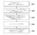
図1を参照すると、図1は本発明の一実施例の表示映像の校正方法を示すフローチャートである。本実施例の表示映像の校正方法は、ニアアイ表示装置に適用される。なお、図1が示すように、ステップS110において、表示映像を分割して、複数のブロック映像を生成する。ステップS120において、ディスプレイで上記ブロック映像を表示し、かつ、これらのブロック映像がライトフィールド素子を通って、合併映像を生成する。なお、図1、図2A、図2B、図2Cおよび図2Dを同時に参照すると、そのうち、図2Aは本発明の実施例のディスプレイおよびライトフィールド素子を示す関係図であり、図2Bは合併映像の生成方式を示す概略図であり、図2Cは前置補償映像の生成方式を示す概略図であり、図2Dは校正後の合併映像の生成方式を示す概略図である。図2Aにおいて、ライトフィールド素子220は複数のサブライトフィールドユニット2211~22MNから構成されている。サブライトフィールドユニット2211~22MNはアレイ状に配列され、かつ、各サブライトフィールドユニット2211~22MNがマイクロレンズであり、マイクロレンズアレイに組み合わせられて、ライトフィールド素子220を形成する。さらに説明すると、図2Aにおいて、ライトフィールド素子220とディスプレイ210は、予め設定された距離で重なって配置され、かつ、ディスプレイ210の表示面がライトフィールド素子220に向いている。かつ、ディスプレイ210の表示面積はサブライトフィールドユニット2211~22MNが覆う総面積より小さい。 Referring to FIG. 1, FIG. 1 is a flow chart showing a method for calibrating a displayed image according to one embodiment of the present invention. The display image calibration method of the present embodiment is applied to a near-eye display device. In addition, as shown in FIG. 1, in step S110, the display image is divided to generate a plurality of block images. In step S120, the block images are displayed on a display and the block images are passed through light field elements to generate a merged image. 1, 2A, 2B, 2C and 2D, of which FIG. 2A is a relationship diagram showing the display and light field element of the embodiment of the present invention, and FIG. 2B is a merged image. FIG. 2C is a schematic diagram illustrating a generation method of a precompensated image; FIG. 2D is a schematic diagram illustrating a generation method of a merged image after calibration; In FIG. 2A, the
また、図2Aおよび図2Bにおいて、ステップS110中の表示映像201は、演算能力を有する制御器202まで伝送されてもよい。制御器202は、図2Aが示すようなディスプレイ210とサブライトフィールドユニット2211~22MNの配置位置関係に基づいて、表示映像201を分割し、複数のブロック映像2011~20MNを生成してもよい。ディスプレイ210によって該表示映像201の前記複数のブロック映像2011~20MNを表示し、かつ図2Aおよび図2Bにおいて、ステップS120で、対応するサブライトフィールドユニット2211~22MNがそれぞれ受け取り、合併映像211を生成する。 Also, in FIGS. 2A and 2B, the displayed
再度図1、図2A、図2Bおよび図2Cを参照すると、ステップS130では映像抽出器(図示せず)を提供してライトフィールド素子220によって生成された合併映像211を抽出し、そして、表示映像201および合併映像211を比較する動作を行って誤差情報を生成する。なお、前記の誤差情報は、表示映像および合併映像において対応する画像間の位置シフトを含むことが可能であり、また表示映像および合併映像において対応する画像間の色差異を含むことも可能であり、さらに表示映像および合併映像において対応する位置にある映像差異を含むことも可能である。表示映像および合併映像間の対応する位置間の映像差異をすべて誤差情報として記録してもよい。 1, 2A, 2B and 2C, step S130 provides an image extractor (not shown) to extract the merged
なお、上記誤差情報を発生させる要素は多くあり、例えば、ニアアイ表示装置中のディスプレイ210の光学情報(例えば、ディスプレイの画素数、画素サイズ、画素形状およびその配列方式)、ライトフィールド素子220の光学情報(例えば、各サブライトフィールドユニットの焦点距離および各隣接するサブライトフィールドユニットの間隔)、ディスプレイ210およびライトフィールド素子220間の空間情報およびニアアイ表示装置のユーザの関連パラメータ(例えば、瞳孔間隔、アイレリーフ(Eye Relief)、瞳孔サイズおよび視線方向など)がある。 There are many factors that generate the above error information. information (e.g., focal length of each sub-light field unit and spacing of each adjacent sub-light field unit), spatial information between
装置内部パラメータの部分について、ニアアイ表示装置の組み立てが完了後、出荷前の測定動作によって得ることができる。そのため、上記の装置内部パラメータは事前にニアアイ表示装置中の記憶装置(図示せず)に記憶され、かつ、ニアアイ表示装置中の制御器(例えば、制御器202)に提供し、ブロック映像を生成する根拠としてもよい。 The part of the device internal parameters can be obtained by the measurement operation before shipping after completing the assembly of the near-eye display device. Therefore, the above device internal parameters are stored in advance in a storage device (not shown) in the near-eye display device, and provided to a controller (eg, controller 202) in the near-eye display device to generate a block image. It may be used as a basis for
ユーザパラメータの部分について、ステップS140で実行されるユーザパラメータを受け取る動作によって、ニアアイ表示装置がユーザパラメータを得ることができる。本発明の実施例において、ユーザは当業者が熟知しているデータ入力手段を用いてユーザパラメータをニアアイ表示装置に入力し、かつニアアイ表示装置中の記憶装置に記憶してもよい。また、本発明の別の実施例において、ニアアイ表示装置には、例えば、瞳孔検出器などの機構を配置して、瞳孔間隔、アイレリーフ、視線方向および瞳孔サイズなど関連するユーザパラメータを自動的に取得してもよい。 For the user parameters portion, the operation of receiving user parameters performed in step S140 allows the near-eye display device to obtain the user parameters. In embodiments of the present invention, a user may enter user parameters into the near-eye display using data input means familiar to those skilled in the art, and store them in memory in the near-eye display. In another embodiment of the invention, the near-eye display device is also provided with a mechanism, for example a pupil detector, to automatically determine relevant user parameters such as interpupillary distance, eye relief, gaze direction and pupil size. may be obtained.
ステップS150では、ユーザパラメータおよびステップS130において取得した誤差情報に基づいて、ブロック映像中の少なくとも一つを調整することで、表示映像を校正する。詳しく言うと、図2Cが示すように、ステップS150では誤差情報の生成に基づいて、表示映像および合併映像間に差異が発生した位置を探し出し、かつ差異が発生した位置に対応するブロック映像を選択して映像調整動作を行い、即ち、ユーザパラメータおよび誤差情報に基づいて、表示映像201中の少なくとも一つの誤差ブロック映像を調整し、かつ前置補償映像201’を生成する。ここで、選択されたブロック映像の数は誤差情報によって決まり、一つであっても複数であってもよく、これについて決まった制限がない。さらに、図2Dが示すように、ユーザは、前置補償映像201’がライトフィールド素子220を通った後形成された校正後合併映像211’を見ることができる。 In step S150, the display image is calibrated by adjusting at least one of the block images based on the user parameters and the error information obtained in step S130. Specifically, as shown in FIG. 2C, in step S150, based on the generation of the error information, find the position where the difference occurs between the display image and the merged image, and select the block image corresponding to the position where the difference occurs. to perform an image adjustment operation, ie adjust at least one error block image in the
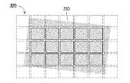
以下は図3Aおよび図3Bを参照するが、図3Aおよび図3Bは本発明の実施例の表示映像の校正方法の一実施方法を示す概略図である。図3Aにおいて、ディスプレイ310とライトフィールド素子320間の位置情報にズレが発生している(例えば、ディスプレイ310とライトフィールド素子320間の水平軸、垂直軸を互いに位置を合わせることができない)。この場合、ディスプレイ310上に複数の矩形枠のブロック映像311、312を表示することにより、ブロック映像毎に一つの特徴パターン(図示せず)を有する。ライトフィールド素子320によって、ブロック映像の特徴パターンは合併映像中に対応する比較対照パターンを生成することができる。特徴パターンおよび対応して生成された比較対照パターンの位置情報をそれぞれ比較して、ライトフィールド素子320とディスプレイ310の相対位置シフト量の誤差情報が得られる。この誤差情報およびユーザパラメータに基づき、ニアアイ表示装置は、ディスプレイ310上におけるブロック映像の表示位置を調整することにより、例えば、ブロック映像311をブロック映像311’に調整し、ブロック映像312をブロック映像312’に調整して、映像校正動作を完了する。 Reference is now made to FIGS. 3A and 3B, which are schematic diagrams illustrating one implementation of a method for calibrating a displayed image according to an embodiment of the present invention. In FIG. 3A, the positional information between
以下は図4Aから図4Cを参照するが、図4Aから図4Cは本発明の実施例の表示映像の校正方法の別の実施方法を示す概略図である。図4Aにおいて、ディスプレイ410とライトフィールド素子420間の距離にズレが発生している(例えば、組立て後の距離が基準値より大きいまたは小さい)。表示映像が複数のブロック映像411に分割され、ディスプレイ410上に特徴パターンCIを有するブロック映像411が表示される。図4Bからわかるように、ブロック映像411中の特徴パターンCIがライトフィールド素子420を通った後、合併映像411’中に比較対照パターンCI’として現れる。制御器(例えば、図2Bの制御器202)は特徴パターンCIおよび比較対照パターンCI’の差異(例えば、位置情報)を比較することで、誤差情報を生成し、かつブロック映像411を誤差ブロック映像と定義することができる。誤差情報に基づいて、表示映像を調整し、前置補償映像を得ることが可能であり、即ち、図4Bが示すブロック映像411中の特徴パターンCIを図4Cが示す誤差ブロック映像(ブロック映像411)の特徴パターンCCIに調整し、これにより、前置補償映像中の誤差ブロック映像(ブロック映像411)の特徴パターンCCIがライトフィールド素子420を通った後、合併映像411’中に対応する比較対照パターンCCI’が現れ、比較対照パターンCCI’が特徴パターンCCIと同じでもよい。 Reference is now made to FIGS. 4A to 4C, which are schematic diagrams illustrating another method for calibrating a displayed image according to an embodiment of the present invention. In FIG. 4A, the distance between the
なお、誤差ブロック映像の数について決められた制限がなく、本発明の実施例は、各ブロック映像中にすべて特徴パターンを設定し、かつ、特徴パターンと対応して生成された比較対照パターンとの間に誤差情報があるか否かを判断することで、各ブロック映像が誤差ブロック映像であるか否かを決定してもよい。 In addition, there is no fixed limit on the number of error block images, and the embodiment of the present invention sets all characteristic patterns in each block image, and compares the characteristic patterns with the comparison patterns generated correspondingly. It may be determined whether each block image is an error block image by determining whether there is error information between them.
前置補償映像の取得方法について、比較対照パターンCI’と特徴パターンCIを相殺する動作で生成することが可能であり、または、特徴パターンCIと比較対照パターンCI’の差異に対しさらに逆処理を行って、前置補償映像を生成するための変換情報を得ることもできる。かつ、同時にユーザパラメータに基づいて前置補償映像を生成することが可能であり、同時に装置内部パラメータおよびユーザパラメータによる表示効果の影響に対し一括校正を行うことが可能である。 Regarding the method of acquiring the precompensated image, it is possible to generate it by canceling the comparison control pattern CI' and the characteristic pattern CI, or to further perform inverse processing on the difference between the characteristic pattern CI and the comparison control pattern CI'. to obtain transformation information for generating a precompensated image. At the same time, it is possible to generate a predistortion image based on the user parameters, and at the same time, it is possible to collectively calibrate the influence of the device internal parameters and the user parameters on the display effect.
以下は図5Aから図5Cを参照するが、図5Aから図5Cは本発明の実施例の表示映像の校正方法のさらに別の実施方法を示す概略図である。本実施方法において、ニアアイ表示装置は装置内部パラメータに基づいて表示映像上に特徴パターンCIを生成することが可能であり、なお、特徴パターンCIはブロック映像511中に生成される。本実施方法において、特徴パターンCIは波長が異なる複数の色領域B1~B3を含む。 Reference is now made to FIGS. 5A to 5C, which are schematic diagrams illustrating still another method for calibrating a displayed image according to an embodiment of the present invention. In this implementation method, the near-eye display device can generate the characteristic pattern CI on the display image based on the device internal parameters, and the characteristic pattern CI is generated in the
ディスプレイ510とライトフィールド素子520間の距離にズレが発生した条件において、ブロック映像511中の特徴パターンCIはライトフィールド素子520を通って、合併映像511’中に比較対照パターンCI’が生成される。比較対照パターンCI’において、色領域B1’~B3’が分散して配列され、かつ色領域B1’~B3’の位置と色領域B1~B3との位置が異なる。 Under the condition that the distance between the
比較対照パターンCI’および特徴パターンCIを比較することにより、誤差情報を得る。この誤差情報およびユーザパラメータに基づいて表示映像を調整し、ニアアイ表示装置に前置補償映像を生成し、即ち、図5Bのブロック映像511中の特徴パターンCIを調整して、図5Cの誤差ブロック映像(ブロック映像511)の特徴パターンCCIにする。これにより、前置補償映像中の誤差ブロック映像(ブロック映像511)の特徴パターンCCIがライトフィールド素子520を通った後、合併映像511’中に対応する比較対照パターンCCI’が現れ、比較対照パターンCCI’が特徴パターンCCIと同じでもよい。ここで、前置補償映像中の誤差ブロック映像の特徴パターンCCIにおいて、色領域CB1~CB3の位置は、表示映像中の特徴パターンCIおよび合併映像511’中の比較対照パターンCI’における各対応色領域B1とB1’、B2とB2’、B3とB3’の位置シフトに基づいて得られる。例を挙げると、特徴パターンCCIにおいて、色領域CB1~CB3の位置は、特徴パターンCI中の色領域B1~B3を比較対照パターンCI’中の色領域B1’~B3’の位置シフトと逆方向へシフトさせることで得られる。 Error information is obtained by comparing the comparison control pattern CI' and the feature pattern CI. Based on this error information and user parameters, the displayed image is adjusted to generate a precompensated image on the near-eye display device, that is, the feature pattern CI in the
以下は図6Aおよび図6Bを参照するが、図6Aおよび図6Bは本発明の実施例の表示映像の校正方法のさらに別の実施方法を示す概略図である。図6Aにおいて、単眼式のニアアイ表示装置を例に、ユーザの目の中心位置が位置E11から位置E12にシフトし、ライトフィールド素子620の中心点と位置合わせができない場合、ユーザには、ライトフィールド素子620によって生成された合併映像に位置シフトが発生した現象が見える。ここで、ディスプレイ610上に特徴パターンを有する複数のブロック映像611を表示し、かつ、合併映像中の特徴パターンが対応して生成された比較対照パターンを検出し、比較対照パターンと対応する特徴パターンとの間の誤差情報を計算する。このように、誤差情報に基づいて前置補償映像を得ることができて、または/およびユーザのフィードバック情報、瞳孔位置、視線方向、瞳距離などユーザパラメータに基づいて前置補償映像を得る。さらに、前置補償映像に基づいて、誤差が発生した誤差ブロック映像(ブロック映像611)をブロック映像611’に調整し、映像校正の動作を完了する。 Reference will now be made to FIGS. 6A and 6B, which are schematic diagrams illustrating still another method for calibrating a displayed image according to an embodiment of the present invention. In FIG. 6A, taking a monocular near-eye display device as an example, when the center position of the user's eye shifts from position E11 to position E12 and cannot be aligned with the center point of the
図6Bにおいて、双眼式のニアアイ表示装置を例に、ユーザの左目の中心位置が位置EL11から位置EL12にシフトし、右目の中心位置が位置ER11から位置ER12にシフトし、それぞれ対応する右眼および左眼のライトフィールド素子620L、620Rの中心点と位置合わせできない場合、ライトフィールド素子620Lおよび620Rによって生成された合併映像のいずれにも位置シフト現象が発生する。従って、図6Aの実施方法で説明したように、左、右目にそれぞれ対応するディスプレイ610Lおよび610Rの映像に対しそれぞれ校正動作を行うことができる。 In FIG. 6B, taking a binocular near-eye display device as an example, the center position of the user's left eye shifts from position EL11 to position EL12, the center position of the right eye shifts from position ER11 to position ER12, and the corresponding right eye and Failure to align with the center point of left eye
図6Bの実施方法からわかるように、本発明の実施例の表示映像の校正方法は、異なるユーザの両目の瞳孔距離に応じて、映像校正の方式で調整を行うことができる。これにより、ニアアイ表示装置において機械式の調整構造を提供してユーザに調整校正の動作を行わせる必要がない。ユーザの便利性を高めるほか、ニアアイ表示装置の生産コストを低減できる。 It can be seen from the implementation method of FIG. 6B that the display image calibration method of the embodiment of the present invention can be adjusted in the manner of image calibration according to the pupillary distance of different users. Accordingly, there is no need to provide a mechanical adjustment structure in the near-eye display device to force the user to perform the operation of adjustment and calibration. In addition to enhancing user convenience, the production cost of the near-eye display device can be reduced.
別の側面において、本発明の実施例では、ユーザの目の焦点距離を検出してユーザパラメータを生成してもよい。かつ、ユーザの目の焦点距離に基づいてブロック映像の表示サイズの調整動作を行い、異なるユーザ全員に明確な合併映像を見せて、さらにニアアイ表示装置の表示効果を高めることができる。 In another aspect, embodiments of the present invention may detect the focal length of a user's eyes to generate user parameters. In addition, the display size of the block image can be adjusted based on the focal length of the user's eye, so that all different users can see a clear merged image, and the display effect of the near-eye display device can be further enhanced.
上記複数の実施方法からわかるように、本発明の実施例のニアアイ表示装置は、ディスプレイ、ライトフィールド素子自体の装置特性、ディスプレイ、ライトフィールド素子間の空間特性、またはユーザ特性によって発生する表示映像の誤差の何れに対しも、前記映像校正の手段によって補償できる。つまり、本発明の実施例のニアアイ表示装置において、映像の調整校正を行う機械装置を設置する必要がなく、生産コストを低減させ、かつ使用上の便利性を高めることができる。 As can be seen from the above-described multiple implementation methods, the near-eye display device of the embodiment of the present invention can be used for the display image generated by the device characteristics of the display and the light field elements themselves, the spatial characteristics between the display and the light field elements, or the user characteristics. Any of the errors can be compensated for by means of the image calibration. That is, in the near-eye display device according to the embodiment of the present invention, there is no need to install a mechanical device for adjusting and calibrating images, so that production costs can be reduced and convenience in use can be enhanced.
比かは図7を参照するが、図7は本発明の一実施例のニアアイ表示装置を示す概略図である。ニアアイ表示装置700は単眼式のニアアイ表示装置である。ニアアイ表示装置700はディスプレイ710、ライトフィールド素子720、映像抽出器730および制御器740を含む。そのうち、ディスプレイ710は複数のブロック映像を表示してもよい。ライトフィールド素子720とディスプレイ710が重なって配置され、ディスプレイ710が表示したブロック映像を受け取り、合併映像を生成する。映像抽出器730は、ライトフィールド素子720が生成する合併映像の横に配置され、かつ合併映像を抽出する。制御器740はディスプレイ710および映像抽出器730をカップリングし、かつ図1の実施例の前記各ステップを実行する。 For comparison, please refer to FIG. 7, which is a schematic diagram showing a near-eye display device according to one embodiment of the present invention. The near-
なお、制御器740はパラメータPARを受け取り、特徴パターンを生成し、およびブロック映像を調整する根拠とする。パラメータPARは、ディスプレイ710およびライトフィールド素子720の装置内部パラメータおよびユーザパラメータを含んでもよい。ディスプレイ710およびライトフィールド素子720の装置内部パラメータは、ディスプレイ710の光学情報、ライトフィールド素子720の光学情報、および、ディスプレイ710とライトフィールド素子720間の空間情報を含んでもよい。ユーザパラメータは、ユーザの瞳孔間隔、アイレリーフ、瞳孔サイズおよび視線方向を含んでもよい。 It should be noted that the
上記のパラメータPARは、ニアアイ表示装置700に内蔵された情報記憶装置(例えば、メモリ)に予め記憶され、制御器740の読み取り動作に提供されてもよい。ユーザパラメータの部分について、ユーザによって、目の視力検査で生成された検査報告を基に入力され、かつ、予め情報記憶装置に記憶され、またはニアアイ表示装置700の入力インターフェース(図示せず)を介して主動でパラメータを入力してもよい。 The above parameter PAR may be pre-stored in an information storage device (eg, memory) built into the near-
制御器740が実行する動作の詳細について、前記実施例および実施方法において詳しく説明したため、ここで省略する。 The details of the operations performed by the
以下は図8を参照するが、図8は本発明のさらに別の実施例のニアアイ表示装置を示す概略図である。ニアアイ表示装置800は双眼式のニアアイ表示装置である。ニアアイ表示装置800は、ディスプレイ810L、810R、ライトフィールド素子820L、820R、映像抽出器830L、830R、制御器840および瞳孔検出器850を含む。そのうち、各ディスプレイ810L、810Rは複数のブロック映像を表示してもよい。ライトフィールド素子820L、820Rはそれぞれディスプレイ810L、810Rと重なって配置され、ライトフィールド素子820L、820Rはそれぞれディスプレイ810L、810Rが表示したブロック映像を受け取り、合併映像を生成する。映像抽出器830L、830Rはそれぞれ、ライトフィールド素子820L、820Rが生成する合併映像の横に配置され、合併映像(例えば、人の目の瞳孔映像)を抽出する。制御器840はディスプレイ810L、810Rおよび映像抽出器830L、830Rをカップリングし、かつ、図1の実施例の前記各ステップを実行する。また、その他の実施例において、ニアアイ表示装置を組立て後、集荷する前に校正してもよく、映像抽出器830L、830Rはそれぞれ像形成位置(予め設定したユーザの目位置)に配置され、合併映像を抽出し、かつ図1の実施例の前記ステップを実行する。 Reference is now made to FIG. 8, which is a schematic diagram showing a near-eye display device according to yet another embodiment of the present invention. The near-
なお、本実施例はさらに瞳孔検出器850を含む。瞳孔検出器850は制御器840にカップリングされ、かつユーザの瞳孔状態、例えば、ユーザの瞳孔距離、瞳孔サイズ、視線方向等を検出し、検出結果を基にユーザパラメータを生成する。 Note that this embodiment further includes a
図7、図8の実施例の各素子のハードウェア構造について、そのうち、制御器740、840は演算能力を有するプロセッサーであってもよい。また、制御器740、840はハードウェア記述言語(Hardware Description Language、HDL)、または当業者が熟知しているその他の任意のデジタル回路設計法方式によって設計され、現場で構成可能な回路アレイ(Field Programmable Gate Array、FPGA)、複合プログラムブルロジックデバイス(Complex Programmable Logic Device、CPLD)または特定用途向け集積回路(Application-specific Integrated Circuit、ASIC)で実行されるハードウェア回路であってもよい。 Regarding the hardware structure of each element in the embodiments of FIGS. 7 and 8, among which the
その他、映像抽出器730、830L、830Rは当業者が熟知している映像抽出装置、例えば、電荷結合素子(Charge-coupled Device、CCD)、CMOS(Complementary
Metal-Oxide Semiconductor)センサーなどを応用して構成されてもよい。瞳孔検出器850も同じく、当業者が熟知している瞳孔検出装置によって構成され、例えば、瞳孔検出器850はユーザの目の映像を抽出するための映像抽出器を含んでもよい。瞳孔検出器850はさらに目の映像中の瞳孔模様を識別することにより、ユーザの瞳孔状態(位置、サイズおよび視線方向)を得ることができる。In addition,
Metal-Oxide Semiconductor) sensor or the like may be applied.
以上をまとめると、本発明は、ディスプレイ上のブロック映像およびライトフィールド素子によって生成された合併映像を比較して、誤差情報を生成し、かつ、誤差情報に基づいて、ユーザパラメータに合わせてブロック映像の少なくとも一つに対し調整動作を行う。これにより、ニアアイ表示装置は機械式の調整装置を提供せずに、装置内部パラメータおよびユーザパラメータによって発生した表示誤差を補償することができて、表示品質を高めるほか、使用上の便利性を高めることもできる。
以上に記載したのは本発明の好ましい実施例であり、本発明の実施範囲がこれに限定されるべきではない。即ち、本発明の請求の範囲および発明の詳細な説明を基に行った簡単な等価変更および修正も本発明の請求範囲内に属する。また、本発明の実施例または請求項のいずれかが必ずしも本発明の開示した目的または利点または特徴を全て満たすとは限らない。その他、要約書と発明の名称は特許文献の検索のために用いられるものであり、本発明の権利範囲を制限するものではない。また、明細書または請求の範囲に言及された「第一」、「第二」などの用語は、素子(element)を命名するめの名称または異なる実施例若しくは範囲を区別するめのものであり、素子の数量の上限または下限を制限するものではない。In summary, the present invention compares the block image on the display and the merged image generated by the light field element to generate error information, and based on the error information, the block image is adapted to user parameters. perform an adjustment operation on at least one of As a result, the near-eye display device can compensate for display errors caused by device internal parameters and user parameters without providing a mechanical adjustment device, thereby improving display quality and enhancing convenience in use. can also
The above descriptions are of preferred embodiments of the present invention, and the scope of implementation of the present invention should not be limited thereto. That is, simple equivalent changes and modifications based on the claims of the invention and the detailed description of the invention also fall within the scope of the claims of the invention. Moreover, not every embodiment of the invention, or any one of the claims, necessarily satisfies all disclosed objects or advantages or features of the invention. In addition, the abstract and the title of the invention are used for searching patent documents and are not intended to limit the scope of the invention. In addition, terms such as "first" and "second" referred to in the specification or claims are names for naming elements or for distinguishing different embodiments or ranges. does not limit the upper or lower limit of the quantity of
Claims (18)
Translated fromJapanese表示映像を分割して、複数のブロック映像を生成するステップと、
ディスプレイによって前記複数のブロック映像を表示し、かつ前記複数のブロック映像がライトフィールド素子を通って、合併映像を生成するステップと、
映像抽出器を提供して前記合併映像を抽出し、前記表示映像および前記合併映像を比較して誤差情報を生成するステップと、
ユーザパラメータを受け取るステップと、
前記ユーザパラメータおよび前記誤差情報に基づいて、前記表示映像中の前記複数のブロック映像の少なくとも一つを調整するステップと、
前記ディスプレイおよび前記ライトフィールド素子の装置内部パラメータを受け取るステップとを含み、
前記ディスプレイおよび前記ライトフィールド素子の装置内部パラメータは、前記ディスプレイの光学情報、前記ライトフィールド素子の光学情報、および前記ディスプレイと前記ライトフィールド素子との間の空間情報を含み、
前記ユーザパラメータは瞳孔間隔、アイレリーフ、瞳孔サイズおよび視線方向を含む
ことを特徴とする表示映像の校正方法。A display image calibration method applied to a near-eye display device,
dividing the display image to generate a plurality of block images;
displaying the plurality of block images by a display and passing the plurality of block images through a light field element to generate a merged image;
providing an image extractor to extract the merged image and comparing the display image and the merged image to generate error information;
receiving user parameters;
adjusting at least one of the plurality of block images in the displayed image based on the user parameter and the error information;
receiving device internal parameters of the display and the light field element;
device internal parameters of the display and the light field elements include optical information of the display, optical information of the light field elements, and spatial information between the display and the light field elements;
The user parameters include interpupillary distance, eye relief, pupil size and viewing direction
A method for calibrating a displayed image, characterized by:
前記装置内部パラメータに基づいて、前記表示映像を生成するステップとを含み、
前記表示映像において、少なくとも一つの特徴パターンを有し、
前記特徴パターンは、前記ライトフィールド素子を通って、前記合併映像中の少なくとも一つの比較対照パターンに形成されることを特徴とする、
請求項1に記載の表示映像の校正方法。The display image calibration method furthercomprises:
generating the display image based onthe device internal parameters;
The display image has at least one characteristic pattern,
wherein the feature pattern is formed into at least one comparison contrast pattern in the merged image through the light field element;
The method for calibrating a displayed image according to claim 1.
前記表示映像の中の前記少なくとも一つの特徴パターンと前記合併映像の中の前記比較対照パターンとの差異を比較して、前記誤差情報を得るステップを含むことを特徴とする、請求項2に記載の表示映像の校正方法。Comparing the display image and the merged image to generate the error information further comprises:
3. The method of claim 2, comprising comparing a difference between the at least one feature pattern in the display image and the comparison pattern in the merged image to obtain the error information. How to calibrate the display image of .
前記少なくとも一つの特徴パターンおよび対応して生成された前記比較対照パターンの位置情報を比較して、前記誤差情報を生成するステップと、
前記誤差情報および前記ユーザパラメータに基づいて、前記誤差情報に対応する少なくとも一つの誤差ブロック映像に対し調整を行うステップとを含むことを特徴とする、請求項3に記載の表示映像の校正方法。adjusting at least one of the plurality of block images based on the user parameter and the error information, further comprising:
comparing position information of the at least one feature pattern and the correspondingly generated comparison pattern to generate the error information;
4. The method of claim 3, further comprising adjusting at least one error block image corresponding to the error information based on the error information and the user parameter.
前記誤差情報および前記ユーザパラメータに基づいて前記表示映像を調整して、前置補償映像を生成するステップと、
前記前置補償映像に基づいて、前記少なくとも一つの誤差ブロック映像を修正するステップとを含むことを特徴とする、請求項4に記載の表示映像の校正方法。making an adjustment to the at least one error block image corresponding to the error information based on the user parameter and the error information;
adjusting the displayed image based on the error information and the user parameters to generate a precompensated image;
and modifying the at least one error block image based on the precompensated image.
前記ユーザパラメータに基づいて各前記ブロック映像を拡大または縮小することによって、各前記ブロック映像を調整するステップを含むことを特徴とする、請求項1に記載の表示映像の校正方法。The display image calibration method further comprises:
2. The method of calibrating a displayed image according to claim 1, comprising adjusting each said block image by enlarging or reducing each said block image based on said user parameter.
前記ライトフィールド素子の複数のサブライトフィールドユニットに基づいて、前記表示映像を前記複数のブロック映像に分割するステップを含むことを特徴とする、請求項1に記載の表示映像の校正方法。The step of dividing the display image to generate the plurality of block images includes:
2. The method of calibrating a displayed image according to claim 1, further comprising dividing the displayed image into the plurality of block images based on a plurality of sub-light field units of the light field element.
ディスプレイ、ライトフィールド素子、映像抽出器および制御器を含み、
前記ディスプレイは複数のブロック映像を表示し、
前記ライトフィールド素子と前記ディスプレイが重なって配置され、前記ディスプレイに表示された前記複数のブロック映像は前記ライトフィールド素子を通って、合併映像を生成し、
前記映像抽出器が前記合併映像を抽出し、
前記制御器は前記ディスプレイおよび前記映像抽出器をカップリングし、かつ、前記制御器は、表示映像を分割して前記複数のブロック映像を生成し、前記表示映像および前記合併映像を比較して誤差情報を生成し、ユーザパラメータを受け取り、および、前記誤差情報および前記ユーザパラメータに基づいて、前記表示映像中の前記複数のブロック映像の少なくとも一つを調整し、
前記制御器は前記ディスプレイおよび前記ライトフィールド素子の装置内部パラメータを受け取り、
前記ディスプレイおよび前記ライトフィールド素子の装置内部パラメータは、前記ディスプレイの光学情報、前記ライトフィールド素子の光学情報、および前記ディスプレイと前記ライトフィールド素子との間の空間情報を含み、
前記ユーザパラメータは、瞳孔間隔、アイレリーフ、瞳孔サイズおよび視線方向を含む
することを特徴とする、ニアアイ表示装置。A near-eye display device,
including a display, light field element, image extractor and controller,
The display displays a plurality of block images,
wherein the light field element and the display are arranged to overlap, and the plurality of block images displayed on the display pass through the light field element to generate a merged image;
the video extractor extracting the merged video;
The controller couples the display and the image extractor, and the controller divides the displayed image to generate the plurality of block images, compares the displayed image and the merged image, and compares the error. generating information, receiving user parameters, and adjusting at least one of the plurality of block images in the displayed image based on the error information and the user parameters;
the controller receives device internal parameters of the display and the light field element;
device internal parameters of the display and the light field elements include optical information of the display, optical information of the light field elements, and spatial information between the display and the light field elements;
The user parameters include interpupillary distance, eye relief, pupil size and viewing direction
A near-eye display device characterized by:
前記装置内部パラメータに基づいて、少なくとも一つの特徴パターンを有する前記表示映像を生成し、
前記特徴パターンは、前記ライトフィールド素子を通って、前記合併映像中の少なくとも一つの比較対照パターンに形成されることを特徴とする、請求項11に記載のニアアイ表示装置。The controller further:
generating the display image having at least one characteristic pattern based onthe device internal parameters;
12. The near-eye display device of claim11 , wherein the feature pattern is formed into at least one comparison pattern in the merged image through the light field element.
前記少なくとも一つの特徴パターンおよび対応して生成された前記比較対照パターンの位置情報を比較して、前記誤差情報を生成し、
前記誤差情報および前記ユーザパラメータに基づいて、前記誤差情報に対応する少なくとも一つの誤差ブロック映像に対し調整を行うことを特徴とする、請求項13に記載のニアアイ表示装置。The controller is
comparing position information of the at least one feature pattern and the correspondingly generated comparative pattern to generate the error information;
14. The near-eye display device as claimed in claim13 , wherein the at least one error block image corresponding to the error information is adjusted based on the error information and the user parameter.
前記誤差情報および前記ユーザパラメータに基づいて前記表示映像を調整することによって、前置補償映像を生成し、
前記前置補償映像に基づいて、前記少なくとも一つの誤差ブロック映像を修正することを特徴とする、請求項14に記載のニアアイ表示装置。The controller is
generating a precompensated image by adjusting the displayed image based on the error information and the user parameters;
15. The near-eye display device of claim14 , wherein the at least one error block image is modified based on the predistortion image.
前記制御器は前記複数のマイクロレンズの位置に基づいて、前記表示映像を前記複数のブロック映像に分割し、
前記複数のマイクロレンズの総面積が前記ディスプレイの表示面積より大きいことを特徴とする、請求項11に記載のニアアイ表示装置。The light field element includes a plurality of microlenses arranged in an array,
the controller dividing the displayed image into the plurality of block images based on the positions of the plurality of microlenses;
12. The near-eye display device according to claim11 , wherein the total area of said plurality of microlenses is larger than the display area of said display.
前記制御器にカップリングされて、ユーザの瞳孔状態を検出し、かつ前記瞳孔状態に基づいて前記ユーザパラメータを生成する瞳孔検出器を含むことを特徴とする、請求項11に記載のニアアイ表示装置。The near-eye display device further includes:
12. A near-eye display device according to claim11 , comprising a pupil detector coupled to said controller for detecting a user's pupillary condition and for generating said user parameter based on said pupillary condition. .
前記第一ライトフィールド素子および前記第二ライトフィールド素子はそれぞれ前記右眼ディスプレイおよび前記左眼ディスプレイに対応し、
前記右眼ディスプレイおよび前記左眼ディスプレイはそれぞれ複数の第一ブロック映像および複数の第二ブロック映像を表示し、
前記第一ライトフィールド素子および前記第二ライトフィールド素子はそれぞれ第一合併映像および第二合併映像を生成することを特徴とする、請求項11に記載のニアアイ表示装置。said display comprises a right eye display and a left eye display, said light field element comprises a first light field element and a second light field element;
the first light field element and the second light field element correspond to the right eye display and the left eye display, respectively;
the right eye display and the left eye display respectively displaying a plurality of first block images and a plurality of second block images;
12. The near-eye display device of claim11 , wherein said first light field element and said second light field element generate a first merged image and a second merged image, respectively.
Applications Claiming Priority (2)
| Application Number | Priority Date | Filing Date | Title |
|---|---|---|---|
| CN201710673880.2ACN109387939B (en) | 2017-08-09 | 2017-08-09 | Near-to-eye display device and correction method of display image thereof |
| CN201710673880.2 | 2017-08-09 |
Publications (2)
| Publication Number | Publication Date |
|---|---|
| JP2019033484A JP2019033484A (en) | 2019-02-28 |
| JP7149759B2true JP7149759B2 (en) | 2022-10-07 |
Family
ID=63293921
Family Applications (1)
| Application Number | Title | Priority Date | Filing Date |
|---|---|---|---|
| JP2018148071AActiveJP7149759B2 (en) | 2017-08-09 | 2018-08-07 | NEAR EYE DISPLAY DEVICE AND CALIBRATION METHOD OF THE DISPLAY VIDEO |
Country Status (4)
| Country | Link |
|---|---|
| US (1) | US10812784B2 (en) |
| EP (1) | EP3441852B1 (en) |
| JP (1) | JP7149759B2 (en) |
| CN (1) | CN109387939B (en) |
Families Citing this family (9)
| Publication number | Priority date | Publication date | Assignee | Title |
|---|---|---|---|---|
| US11119253B2 (en) | 2018-09-28 | 2021-09-14 | Avalon Holographics Inc. | Direct projection light field display |
| JP2022073094A (en)* | 2020-10-30 | 2022-05-17 | セイコーエプソン株式会社 | Optical module and virtual image display device |
| US11842662B2 (en) | 2021-05-13 | 2023-12-12 | Coretronic Corporation | Light field near-eye display device for automatically adjusting image data according to current eye relief and method thereof |
| US11841513B2 (en)* | 2021-05-13 | 2023-12-12 | Coretronic Corporation | Light field near-eye display device and method of light field near-eye display |
| CN115343848B (en)* | 2021-05-13 | 2025-09-23 | 中强光电股份有限公司 | Light field near-eye display device and light field near-eye display method |
| CN115494640A (en) | 2021-06-17 | 2022-12-20 | 中强光电股份有限公司 | Light field near-eye display for generating virtual reality image and method thereof |
| US20230196522A1 (en)* | 2021-12-17 | 2023-06-22 | SoliDDD Corp. | Plenoptic image tile organization for single image display or capture |
| CN116743982A (en)* | 2022-03-04 | 2023-09-12 | 中强光电股份有限公司 | Image display system and display method |
| JP2024016726A (en)* | 2022-07-26 | 2024-02-07 | Kddi株式会社 | Computer-generated hologram reproduction device and its structured illumination calibration method and program |
Citations (3)
| Publication number | Priority date | Publication date | Assignee | Title |
|---|---|---|---|---|
| WO2016019204A1 (en) | 2014-07-31 | 2016-02-04 | Mcgrew Stephen P | Image and wave field projection through diffusive media |
| WO2017066802A1 (en) | 2015-10-16 | 2017-04-20 | Ostendo Technologies, Inc. | Dual-mode augmented/virtual reality (ar/vr) near-eye wearable displays |
| WO2017079329A1 (en) | 2015-11-04 | 2017-05-11 | Magic Leap, Inc. | Dynamic display calibration based on eye-tracking |
Family Cites Families (9)
| Publication number | Priority date | Publication date | Assignee | Title |
|---|---|---|---|---|
| US20090273662A1 (en)* | 2006-03-15 | 2009-11-05 | Zebra Imaging, Inc. | Systems and Methods for Calibrating a Hogel 3D Display |
| US8736674B2 (en)* | 2010-09-23 | 2014-05-27 | Dolby Laboratories Licensing Corporation | Method and system for 3D display calibration with feedback determined by a camera device |
| JP6061552B2 (en)* | 2012-08-23 | 2017-01-18 | キヤノン株式会社 | Head-mounted image display device |
| US20150262424A1 (en) | 2013-01-31 | 2015-09-17 | Google Inc. | Depth and Focus Discrimination for a Head-mountable device using a Light-Field Display System |
| JP6406252B2 (en)* | 2013-07-16 | 2018-10-17 | ソニー株式会社 | Display device |
| JP6459262B2 (en)* | 2014-07-09 | 2019-01-30 | 株式会社ニコン | Head mounted display |
| JP2016031439A (en)* | 2014-07-28 | 2016-03-07 | ソニー株式会社 | Information processing apparatus and information processing method, computer program, and image display system |
| US10529059B2 (en)* | 2014-08-11 | 2020-01-07 | The Regents Of The University Of California | Vision correcting display with aberration compensation using inverse blurring and a light field display |
| CN104914575B (en) | 2014-09-29 | 2017-11-14 | 北京蚁视科技有限公司 | Microlens array formula near-to-eye with diopter detection means |
- 2017
- 2017-08-09CNCN201710673880.2Apatent/CN109387939B/enactiveActive
- 2018
- 2018-08-02EPEP18186991.8Apatent/EP3441852B1/enactiveActive
- 2018-08-07USUS16/056,536patent/US10812784B2/enactiveActive
- 2018-08-07JPJP2018148071Apatent/JP7149759B2/enactiveActive
Patent Citations (4)
| Publication number | Priority date | Publication date | Assignee | Title |
|---|---|---|---|---|
| WO2016019204A1 (en) | 2014-07-31 | 2016-02-04 | Mcgrew Stephen P | Image and wave field projection through diffusive media |
| WO2017066802A1 (en) | 2015-10-16 | 2017-04-20 | Ostendo Technologies, Inc. | Dual-mode augmented/virtual reality (ar/vr) near-eye wearable displays |
| WO2017079329A1 (en) | 2015-11-04 | 2017-05-11 | Magic Leap, Inc. | Dynamic display calibration based on eye-tracking |
| JP2019501564A (en) | 2015-11-04 | 2019-01-17 | マジック リープ, インコーポレイテッドMagic Leap,Inc. | Dynamic display calibration based on eye tracking |
Also Published As
| Publication number | Publication date |
|---|---|
| EP3441852B1 (en) | 2020-11-11 |
| CN109387939B (en) | 2021-02-12 |
| US10812784B2 (en) | 2020-10-20 |
| EP3441852A1 (en) | 2019-02-13 |
| US20190052866A1 (en) | 2019-02-14 |
| CN109387939A (en) | 2019-02-26 |
| JP2019033484A (en) | 2019-02-28 |
Similar Documents
| Publication | Publication Date | Title |
|---|---|---|
| JP7149759B2 (en) | NEAR EYE DISPLAY DEVICE AND CALIBRATION METHOD OF THE DISPLAY VIDEO | |
| JP6308513B2 (en) | Stereoscopic image display apparatus, image processing apparatus, and stereoscopic image processing method | |
| JP6354838B2 (en) | Image pickup device, image pickup apparatus, and image processing apparatus | |
| JP5464279B2 (en) | Image processing apparatus, program thereof, and image processing method | |
| TW201320717A (en) | Method of displaying 3D image | |
| US20140139647A1 (en) | Stereoscopic image display device | |
| JPWO2015132828A1 (en) | Video display method and video display device | |
| JP2021101238A (en) | Display device and display method | |
| KR101641406B1 (en) | Stereo camera | |
| KR102128336B1 (en) | 3d image distortion correction system and method | |
| TW201505419A (en) | Method capable of improving 3D displayer crosstalk | |
| CN107155102A (en) | 3D automatic focusing display method and system thereof | |
| CN108259888A (en) | The test method and system of stereo display effect | |
| Chen et al. | Binocular mismatch induced by luminance discrepancies on stereoscopic images | |
| JP4977278B1 (en) | Image processing apparatus, stereoscopic image display apparatus, and image processing method | |
| TWI462569B (en) | 3d video camera and associated control method | |
| US20160065941A1 (en) | Three-dimensional image capturing apparatus and storage medium storing three-dimensional image capturing program | |
| TWI508524B (en) | Method and system for automatic adjusting auto-stereoscopic 3d display device | |
| JP5982907B2 (en) | Image processing apparatus, image processing method, and program | |
| TWI450594B (en) | Cross-color image processing systems and methods for sharpness enhancement | |
| Nam et al. | Analysis of blur characteristics on 3D displays | |
| Yamanoue et al. | Stereoscopic HDTV: research at NHK science and technology research laboratories | |
| JP2025021672A (en) | Image processing device, image processing method, and program | |
| KR101742230B1 (en) | Apparatus and method for stereotest | |
| CN118692346A (en) | Display device and method of driving the same |
Legal Events
| Date | Code | Title | Description |
|---|---|---|---|
| A621 | Written request for application examination | Free format text:JAPANESE INTERMEDIATE CODE: A621 Effective date:20210104 | |
| A977 | Report on retrieval | Free format text:JAPANESE INTERMEDIATE CODE: A971007 Effective date:20220128 | |
| A131 | Notification of reasons for refusal | Free format text:JAPANESE INTERMEDIATE CODE: A131 Effective date:20220208 | |
| A521 | Request for written amendment filed | Free format text:JAPANESE INTERMEDIATE CODE: A523 Effective date:20220427 | |
| TRDD | Decision of grant or rejection written | ||
| A01 | Written decision to grant a patent or to grant a registration (utility model) | Free format text:JAPANESE INTERMEDIATE CODE: A01 Effective date:20220913 | |
| A61 | First payment of annual fees (during grant procedure) | Free format text:JAPANESE INTERMEDIATE CODE: A61 Effective date:20220927 | |
| R150 | Certificate of patent or registration of utility model | Ref document number:7149759 Country of ref document:JP Free format text:JAPANESE INTERMEDIATE CODE: R150 | |
| R250 | Receipt of annual fees | Free format text:JAPANESE INTERMEDIATE CODE: R250 |