JP7149230B2 - Vehicle system and hybrid vehicle - Google Patents
Vehicle system and hybrid vehicleDownload PDFInfo
- Publication number
- JP7149230B2 JP7149230B2JP2019118985AJP2019118985AJP7149230B2JP 7149230 B2JP7149230 B2JP 7149230B2JP 2019118985 AJP2019118985 AJP 2019118985AJP 2019118985 AJP2019118985 AJP 2019118985AJP 7149230 B2JP7149230 B2JP 7149230B2
- Authority
- JP
- Japan
- Prior art keywords
- mode
- display
- switching
- battery
- vehicle
- Prior art date
- Legal status (The legal status is an assumption and is not a legal conclusion. Google has not performed a legal analysis and makes no representation as to the accuracy of the status listed.)
- Active
Links
Images


Classifications
- B—PERFORMING OPERATIONS; TRANSPORTING
- B60—VEHICLES IN GENERAL
- B60W—CONJOINT CONTROL OF VEHICLE SUB-UNITS OF DIFFERENT TYPE OR DIFFERENT FUNCTION; CONTROL SYSTEMS SPECIALLY ADAPTED FOR HYBRID VEHICLES; ROAD VEHICLE DRIVE CONTROL SYSTEMS FOR PURPOSES NOT RELATED TO THE CONTROL OF A PARTICULAR SUB-UNIT
- B60W20/00—Control systems specially adapted for hybrid vehicles
- B60W20/10—Controlling the power contribution of each of the prime movers to meet required power demand
- B60W20/15—Control strategies specially adapted for achieving a particular effect
- B—PERFORMING OPERATIONS; TRANSPORTING
- B60—VEHICLES IN GENERAL
- B60L—PROPULSION OF ELECTRICALLY-PROPELLED VEHICLES; SUPPLYING ELECTRIC POWER FOR AUXILIARY EQUIPMENT OF ELECTRICALLY-PROPELLED VEHICLES; ELECTRODYNAMIC BRAKE SYSTEMS FOR VEHICLES IN GENERAL; MAGNETIC SUSPENSION OR LEVITATION FOR VEHICLES; MONITORING OPERATING VARIABLES OF ELECTRICALLY-PROPELLED VEHICLES; ELECTRIC SAFETY DEVICES FOR ELECTRICALLY-PROPELLED VEHICLES
- B60L50/00—Electric propulsion with power supplied within the vehicle
- B60L50/10—Electric propulsion with power supplied within the vehicle using propulsion power supplied by engine-driven generators, e.g. generators driven by combustion engines
- B60L50/15—Electric propulsion with power supplied within the vehicle using propulsion power supplied by engine-driven generators, e.g. generators driven by combustion engines with additional electric power supply
- B—PERFORMING OPERATIONS; TRANSPORTING
- B60—VEHICLES IN GENERAL
- B60K—ARRANGEMENT OR MOUNTING OF PROPULSION UNITS OR OF TRANSMISSIONS IN VEHICLES; ARRANGEMENT OR MOUNTING OF PLURAL DIVERSE PRIME-MOVERS IN VEHICLES; AUXILIARY DRIVES FOR VEHICLES; INSTRUMENTATION OR DASHBOARDS FOR VEHICLES; ARRANGEMENTS IN CONNECTION WITH COOLING, AIR INTAKE, GAS EXHAUST OR FUEL SUPPLY OF PROPULSION UNITS IN VEHICLES
- B60K35/00—Instruments specially adapted for vehicles; Arrangement of instruments in or on vehicles
- B60K35/20—Output arrangements, i.e. from vehicle to user, associated with vehicle functions or specially adapted therefor
- B60K35/21—Output arrangements, i.e. from vehicle to user, associated with vehicle functions or specially adapted therefor using visual output, e.g. blinking lights or matrix displays
- B60K35/22—Display screens
- B—PERFORMING OPERATIONS; TRANSPORTING
- B60—VEHICLES IN GENERAL
- B60K—ARRANGEMENT OR MOUNTING OF PROPULSION UNITS OR OF TRANSMISSIONS IN VEHICLES; ARRANGEMENT OR MOUNTING OF PLURAL DIVERSE PRIME-MOVERS IN VEHICLES; AUXILIARY DRIVES FOR VEHICLES; INSTRUMENTATION OR DASHBOARDS FOR VEHICLES; ARRANGEMENTS IN CONNECTION WITH COOLING, AIR INTAKE, GAS EXHAUST OR FUEL SUPPLY OF PROPULSION UNITS IN VEHICLES
- B60K35/00—Instruments specially adapted for vehicles; Arrangement of instruments in or on vehicles
- B60K35/80—Arrangements for controlling instruments
- B60K35/81—Arrangements for controlling instruments for controlling displays
- B—PERFORMING OPERATIONS; TRANSPORTING
- B60—VEHICLES IN GENERAL
- B60K—ARRANGEMENT OR MOUNTING OF PROPULSION UNITS OR OF TRANSMISSIONS IN VEHICLES; ARRANGEMENT OR MOUNTING OF PLURAL DIVERSE PRIME-MOVERS IN VEHICLES; AUXILIARY DRIVES FOR VEHICLES; INSTRUMENTATION OR DASHBOARDS FOR VEHICLES; ARRANGEMENTS IN CONNECTION WITH COOLING, AIR INTAKE, GAS EXHAUST OR FUEL SUPPLY OF PROPULSION UNITS IN VEHICLES
- B60K6/00—Arrangement or mounting of plural diverse prime-movers for mutual or common propulsion, e.g. hybrid propulsion systems comprising electric motors and internal combustion engines
- B60K6/20—Arrangement or mounting of plural diverse prime-movers for mutual or common propulsion, e.g. hybrid propulsion systems comprising electric motors and internal combustion engines the prime-movers consisting of electric motors and internal combustion engines, e.g. HEVs
- B60K6/22—Arrangement or mounting of plural diverse prime-movers for mutual or common propulsion, e.g. hybrid propulsion systems comprising electric motors and internal combustion engines the prime-movers consisting of electric motors and internal combustion engines, e.g. HEVs characterised by apparatus, components or means specially adapted for HEVs
- B60K6/24—Arrangement or mounting of plural diverse prime-movers for mutual or common propulsion, e.g. hybrid propulsion systems comprising electric motors and internal combustion engines the prime-movers consisting of electric motors and internal combustion engines, e.g. HEVs characterised by apparatus, components or means specially adapted for HEVs characterised by the combustion engines
- B—PERFORMING OPERATIONS; TRANSPORTING
- B60—VEHICLES IN GENERAL
- B60K—ARRANGEMENT OR MOUNTING OF PROPULSION UNITS OR OF TRANSMISSIONS IN VEHICLES; ARRANGEMENT OR MOUNTING OF PLURAL DIVERSE PRIME-MOVERS IN VEHICLES; AUXILIARY DRIVES FOR VEHICLES; INSTRUMENTATION OR DASHBOARDS FOR VEHICLES; ARRANGEMENTS IN CONNECTION WITH COOLING, AIR INTAKE, GAS EXHAUST OR FUEL SUPPLY OF PROPULSION UNITS IN VEHICLES
- B60K6/00—Arrangement or mounting of plural diverse prime-movers for mutual or common propulsion, e.g. hybrid propulsion systems comprising electric motors and internal combustion engines
- B60K6/20—Arrangement or mounting of plural diverse prime-movers for mutual or common propulsion, e.g. hybrid propulsion systems comprising electric motors and internal combustion engines the prime-movers consisting of electric motors and internal combustion engines, e.g. HEVs
- B60K6/22—Arrangement or mounting of plural diverse prime-movers for mutual or common propulsion, e.g. hybrid propulsion systems comprising electric motors and internal combustion engines the prime-movers consisting of electric motors and internal combustion engines, e.g. HEVs characterised by apparatus, components or means specially adapted for HEVs
- B60K6/26—Arrangement or mounting of plural diverse prime-movers for mutual or common propulsion, e.g. hybrid propulsion systems comprising electric motors and internal combustion engines the prime-movers consisting of electric motors and internal combustion engines, e.g. HEVs characterised by apparatus, components or means specially adapted for HEVs characterised by the motors or the generators
- B—PERFORMING OPERATIONS; TRANSPORTING
- B60—VEHICLES IN GENERAL
- B60K—ARRANGEMENT OR MOUNTING OF PROPULSION UNITS OR OF TRANSMISSIONS IN VEHICLES; ARRANGEMENT OR MOUNTING OF PLURAL DIVERSE PRIME-MOVERS IN VEHICLES; AUXILIARY DRIVES FOR VEHICLES; INSTRUMENTATION OR DASHBOARDS FOR VEHICLES; ARRANGEMENTS IN CONNECTION WITH COOLING, AIR INTAKE, GAS EXHAUST OR FUEL SUPPLY OF PROPULSION UNITS IN VEHICLES
- B60K6/00—Arrangement or mounting of plural diverse prime-movers for mutual or common propulsion, e.g. hybrid propulsion systems comprising electric motors and internal combustion engines
- B60K6/20—Arrangement or mounting of plural diverse prime-movers for mutual or common propulsion, e.g. hybrid propulsion systems comprising electric motors and internal combustion engines the prime-movers consisting of electric motors and internal combustion engines, e.g. HEVs
- B60K6/22—Arrangement or mounting of plural diverse prime-movers for mutual or common propulsion, e.g. hybrid propulsion systems comprising electric motors and internal combustion engines the prime-movers consisting of electric motors and internal combustion engines, e.g. HEVs characterised by apparatus, components or means specially adapted for HEVs
- B60K6/28—Arrangement or mounting of plural diverse prime-movers for mutual or common propulsion, e.g. hybrid propulsion systems comprising electric motors and internal combustion engines the prime-movers consisting of electric motors and internal combustion engines, e.g. HEVs characterised by apparatus, components or means specially adapted for HEVs characterised by the electric energy storing means, e.g. batteries or capacitors
- B—PERFORMING OPERATIONS; TRANSPORTING
- B60—VEHICLES IN GENERAL
- B60K—ARRANGEMENT OR MOUNTING OF PROPULSION UNITS OR OF TRANSMISSIONS IN VEHICLES; ARRANGEMENT OR MOUNTING OF PLURAL DIVERSE PRIME-MOVERS IN VEHICLES; AUXILIARY DRIVES FOR VEHICLES; INSTRUMENTATION OR DASHBOARDS FOR VEHICLES; ARRANGEMENTS IN CONNECTION WITH COOLING, AIR INTAKE, GAS EXHAUST OR FUEL SUPPLY OF PROPULSION UNITS IN VEHICLES
- B60K6/00—Arrangement or mounting of plural diverse prime-movers for mutual or common propulsion, e.g. hybrid propulsion systems comprising electric motors and internal combustion engines
- B60K6/20—Arrangement or mounting of plural diverse prime-movers for mutual or common propulsion, e.g. hybrid propulsion systems comprising electric motors and internal combustion engines the prime-movers consisting of electric motors and internal combustion engines, e.g. HEVs
- B60K6/22—Arrangement or mounting of plural diverse prime-movers for mutual or common propulsion, e.g. hybrid propulsion systems comprising electric motors and internal combustion engines the prime-movers consisting of electric motors and internal combustion engines, e.g. HEVs characterised by apparatus, components or means specially adapted for HEVs
- B60K6/38—Arrangement or mounting of plural diverse prime-movers for mutual or common propulsion, e.g. hybrid propulsion systems comprising electric motors and internal combustion engines the prime-movers consisting of electric motors and internal combustion engines, e.g. HEVs characterised by apparatus, components or means specially adapted for HEVs characterised by the driveline clutches
- B60K6/387—Actuated clutches, i.e. clutches engaged or disengaged by electric, hydraulic or mechanical actuating means
- B—PERFORMING OPERATIONS; TRANSPORTING
- B60—VEHICLES IN GENERAL
- B60K—ARRANGEMENT OR MOUNTING OF PROPULSION UNITS OR OF TRANSMISSIONS IN VEHICLES; ARRANGEMENT OR MOUNTING OF PLURAL DIVERSE PRIME-MOVERS IN VEHICLES; AUXILIARY DRIVES FOR VEHICLES; INSTRUMENTATION OR DASHBOARDS FOR VEHICLES; ARRANGEMENTS IN CONNECTION WITH COOLING, AIR INTAKE, GAS EXHAUST OR FUEL SUPPLY OF PROPULSION UNITS IN VEHICLES
- B60K6/00—Arrangement or mounting of plural diverse prime-movers for mutual or common propulsion, e.g. hybrid propulsion systems comprising electric motors and internal combustion engines
- B60K6/20—Arrangement or mounting of plural diverse prime-movers for mutual or common propulsion, e.g. hybrid propulsion systems comprising electric motors and internal combustion engines the prime-movers consisting of electric motors and internal combustion engines, e.g. HEVs
- B60K6/42—Arrangement or mounting of plural diverse prime-movers for mutual or common propulsion, e.g. hybrid propulsion systems comprising electric motors and internal combustion engines the prime-movers consisting of electric motors and internal combustion engines, e.g. HEVs characterised by the architecture of the hybrid electric vehicle
- B60K6/44—Series-parallel type
- B60K6/442—Series-parallel switching type
- B—PERFORMING OPERATIONS; TRANSPORTING
- B60—VEHICLES IN GENERAL
- B60L—PROPULSION OF ELECTRICALLY-PROPELLED VEHICLES; SUPPLYING ELECTRIC POWER FOR AUXILIARY EQUIPMENT OF ELECTRICALLY-PROPELLED VEHICLES; ELECTRODYNAMIC BRAKE SYSTEMS FOR VEHICLES IN GENERAL; MAGNETIC SUSPENSION OR LEVITATION FOR VEHICLES; MONITORING OPERATING VARIABLES OF ELECTRICALLY-PROPELLED VEHICLES; ELECTRIC SAFETY DEVICES FOR ELECTRICALLY-PROPELLED VEHICLES
- B60L50/00—Electric propulsion with power supplied within the vehicle
- B60L50/10—Electric propulsion with power supplied within the vehicle using propulsion power supplied by engine-driven generators, e.g. generators driven by combustion engines
- B60L50/16—Electric propulsion with power supplied within the vehicle using propulsion power supplied by engine-driven generators, e.g. generators driven by combustion engines with provision for separate direct mechanical propulsion
- B—PERFORMING OPERATIONS; TRANSPORTING
- B60—VEHICLES IN GENERAL
- B60L—PROPULSION OF ELECTRICALLY-PROPELLED VEHICLES; SUPPLYING ELECTRIC POWER FOR AUXILIARY EQUIPMENT OF ELECTRICALLY-PROPELLED VEHICLES; ELECTRODYNAMIC BRAKE SYSTEMS FOR VEHICLES IN GENERAL; MAGNETIC SUSPENSION OR LEVITATION FOR VEHICLES; MONITORING OPERATING VARIABLES OF ELECTRICALLY-PROPELLED VEHICLES; ELECTRIC SAFETY DEVICES FOR ELECTRICALLY-PROPELLED VEHICLES
- B60L50/00—Electric propulsion with power supplied within the vehicle
- B60L50/50—Electric propulsion with power supplied within the vehicle using propulsion power supplied by batteries or fuel cells
- B60L50/60—Electric propulsion with power supplied within the vehicle using propulsion power supplied by batteries or fuel cells using power supplied by batteries
- B60L50/61—Electric propulsion with power supplied within the vehicle using propulsion power supplied by batteries or fuel cells using power supplied by batteries by batteries charged by engine-driven generators, e.g. series hybrid electric vehicles
- B—PERFORMING OPERATIONS; TRANSPORTING
- B60—VEHICLES IN GENERAL
- B60L—PROPULSION OF ELECTRICALLY-PROPELLED VEHICLES; SUPPLYING ELECTRIC POWER FOR AUXILIARY EQUIPMENT OF ELECTRICALLY-PROPELLED VEHICLES; ELECTRODYNAMIC BRAKE SYSTEMS FOR VEHICLES IN GENERAL; MAGNETIC SUSPENSION OR LEVITATION FOR VEHICLES; MONITORING OPERATING VARIABLES OF ELECTRICALLY-PROPELLED VEHICLES; ELECTRIC SAFETY DEVICES FOR ELECTRICALLY-PROPELLED VEHICLES
- B60L58/00—Methods or circuit arrangements for monitoring or controlling batteries or fuel cells, specially adapted for electric vehicles
- B60L58/10—Methods or circuit arrangements for monitoring or controlling batteries or fuel cells, specially adapted for electric vehicles for monitoring or controlling batteries
- B60L58/12—Methods or circuit arrangements for monitoring or controlling batteries or fuel cells, specially adapted for electric vehicles for monitoring or controlling batteries responding to state of charge [SoC]
- B60L58/13—Maintaining the SoC within a determined range
- B—PERFORMING OPERATIONS; TRANSPORTING
- B60—VEHICLES IN GENERAL
- B60L—PROPULSION OF ELECTRICALLY-PROPELLED VEHICLES; SUPPLYING ELECTRIC POWER FOR AUXILIARY EQUIPMENT OF ELECTRICALLY-PROPELLED VEHICLES; ELECTRODYNAMIC BRAKE SYSTEMS FOR VEHICLES IN GENERAL; MAGNETIC SUSPENSION OR LEVITATION FOR VEHICLES; MONITORING OPERATING VARIABLES OF ELECTRICALLY-PROPELLED VEHICLES; ELECTRIC SAFETY DEVICES FOR ELECTRICALLY-PROPELLED VEHICLES
- B60L58/00—Methods or circuit arrangements for monitoring or controlling batteries or fuel cells, specially adapted for electric vehicles
- B60L58/10—Methods or circuit arrangements for monitoring or controlling batteries or fuel cells, specially adapted for electric vehicles for monitoring or controlling batteries
- B60L58/16—Methods or circuit arrangements for monitoring or controlling batteries or fuel cells, specially adapted for electric vehicles for monitoring or controlling batteries responding to battery ageing, e.g. to the number of charging cycles or the state of health [SoH]
- B—PERFORMING OPERATIONS; TRANSPORTING
- B60—VEHICLES IN GENERAL
- B60L—PROPULSION OF ELECTRICALLY-PROPELLED VEHICLES; SUPPLYING ELECTRIC POWER FOR AUXILIARY EQUIPMENT OF ELECTRICALLY-PROPELLED VEHICLES; ELECTRODYNAMIC BRAKE SYSTEMS FOR VEHICLES IN GENERAL; MAGNETIC SUSPENSION OR LEVITATION FOR VEHICLES; MONITORING OPERATING VARIABLES OF ELECTRICALLY-PROPELLED VEHICLES; ELECTRIC SAFETY DEVICES FOR ELECTRICALLY-PROPELLED VEHICLES
- B60L58/00—Methods or circuit arrangements for monitoring or controlling batteries or fuel cells, specially adapted for electric vehicles
- B60L58/10—Methods or circuit arrangements for monitoring or controlling batteries or fuel cells, specially adapted for electric vehicles for monitoring or controlling batteries
- B60L58/24—Methods or circuit arrangements for monitoring or controlling batteries or fuel cells, specially adapted for electric vehicles for monitoring or controlling batteries for controlling the temperature of batteries
- B60L58/26—Methods or circuit arrangements for monitoring or controlling batteries or fuel cells, specially adapted for electric vehicles for monitoring or controlling batteries for controlling the temperature of batteries by cooling
- B—PERFORMING OPERATIONS; TRANSPORTING
- B60—VEHICLES IN GENERAL
- B60R—VEHICLES, VEHICLE FITTINGS, OR VEHICLE PARTS, NOT OTHERWISE PROVIDED FOR
- B60R16/00—Electric or fluid circuits specially adapted for vehicles and not otherwise provided for; Arrangement of elements of electric or fluid circuits specially adapted for vehicles and not otherwise provided for
- B60R16/02—Electric or fluid circuits specially adapted for vehicles and not otherwise provided for; Arrangement of elements of electric or fluid circuits specially adapted for vehicles and not otherwise provided for electric constitutive elements
- B60R16/023—Electric or fluid circuits specially adapted for vehicles and not otherwise provided for; Arrangement of elements of electric or fluid circuits specially adapted for vehicles and not otherwise provided for electric constitutive elements for transmission of signals between vehicle parts or subsystems
- B60R16/0231—Circuits relating to the driving or the functioning of the vehicle
- B60R16/0232—Circuits relating to the driving or the functioning of the vehicle for measuring vehicle parameters and indicating critical, abnormal or dangerous conditions
- B—PERFORMING OPERATIONS; TRANSPORTING
- B60—VEHICLES IN GENERAL
- B60W—CONJOINT CONTROL OF VEHICLE SUB-UNITS OF DIFFERENT TYPE OR DIFFERENT FUNCTION; CONTROL SYSTEMS SPECIALLY ADAPTED FOR HYBRID VEHICLES; ROAD VEHICLE DRIVE CONTROL SYSTEMS FOR PURPOSES NOT RELATED TO THE CONTROL OF A PARTICULAR SUB-UNIT
- B60W20/00—Control systems specially adapted for hybrid vehicles
- B60W20/20—Control strategies involving selection of hybrid configuration, e.g. selection between series or parallel configuration
- B—PERFORMING OPERATIONS; TRANSPORTING
- B60—VEHICLES IN GENERAL
- B60K—ARRANGEMENT OR MOUNTING OF PROPULSION UNITS OR OF TRANSMISSIONS IN VEHICLES; ARRANGEMENT OR MOUNTING OF PLURAL DIVERSE PRIME-MOVERS IN VEHICLES; AUXILIARY DRIVES FOR VEHICLES; INSTRUMENTATION OR DASHBOARDS FOR VEHICLES; ARRANGEMENTS IN CONNECTION WITH COOLING, AIR INTAKE, GAS EXHAUST OR FUEL SUPPLY OF PROPULSION UNITS IN VEHICLES
- B60K6/00—Arrangement or mounting of plural diverse prime-movers for mutual or common propulsion, e.g. hybrid propulsion systems comprising electric motors and internal combustion engines
- B60K6/20—Arrangement or mounting of plural diverse prime-movers for mutual or common propulsion, e.g. hybrid propulsion systems comprising electric motors and internal combustion engines the prime-movers consisting of electric motors and internal combustion engines, e.g. HEVs
- B60K6/42—Arrangement or mounting of plural diverse prime-movers for mutual or common propulsion, e.g. hybrid propulsion systems comprising electric motors and internal combustion engines the prime-movers consisting of electric motors and internal combustion engines, e.g. HEVs characterised by the architecture of the hybrid electric vehicle
- B60K6/48—Parallel type
- B60K2006/4808—Electric machine connected or connectable to gearbox output shaft
- B—PERFORMING OPERATIONS; TRANSPORTING
- B60—VEHICLES IN GENERAL
- B60K—ARRANGEMENT OR MOUNTING OF PROPULSION UNITS OR OF TRANSMISSIONS IN VEHICLES; ARRANGEMENT OR MOUNTING OF PLURAL DIVERSE PRIME-MOVERS IN VEHICLES; AUXILIARY DRIVES FOR VEHICLES; INSTRUMENTATION OR DASHBOARDS FOR VEHICLES; ARRANGEMENTS IN CONNECTION WITH COOLING, AIR INTAKE, GAS EXHAUST OR FUEL SUPPLY OF PROPULSION UNITS IN VEHICLES
- B60K2360/00—Indexing scheme associated with groups B60K35/00 or B60K37/00 relating to details of instruments or dashboards
- B60K2360/16—Type of output information
- B60K2360/169—Remaining operating distance or charge
- B—PERFORMING OPERATIONS; TRANSPORTING
- B60—VEHICLES IN GENERAL
- B60K—ARRANGEMENT OR MOUNTING OF PROPULSION UNITS OR OF TRANSMISSIONS IN VEHICLES; ARRANGEMENT OR MOUNTING OF PLURAL DIVERSE PRIME-MOVERS IN VEHICLES; AUXILIARY DRIVES FOR VEHICLES; INSTRUMENTATION OR DASHBOARDS FOR VEHICLES; ARRANGEMENTS IN CONNECTION WITH COOLING, AIR INTAKE, GAS EXHAUST OR FUEL SUPPLY OF PROPULSION UNITS IN VEHICLES
- B60K2360/00—Indexing scheme associated with groups B60K35/00 or B60K37/00 relating to details of instruments or dashboards
- B60K2360/16—Type of output information
- B60K2360/172—Driving mode indication
- B—PERFORMING OPERATIONS; TRANSPORTING
- B60—VEHICLES IN GENERAL
- B60K—ARRANGEMENT OR MOUNTING OF PROPULSION UNITS OR OF TRANSMISSIONS IN VEHICLES; ARRANGEMENT OR MOUNTING OF PLURAL DIVERSE PRIME-MOVERS IN VEHICLES; AUXILIARY DRIVES FOR VEHICLES; INSTRUMENTATION OR DASHBOARDS FOR VEHICLES; ARRANGEMENTS IN CONNECTION WITH COOLING, AIR INTAKE, GAS EXHAUST OR FUEL SUPPLY OF PROPULSION UNITS IN VEHICLES
- B60K35/00—Instruments specially adapted for vehicles; Arrangement of instruments in or on vehicles
- B60K35/20—Output arrangements, i.e. from vehicle to user, associated with vehicle functions or specially adapted therefor
- B60K35/28—Output arrangements, i.e. from vehicle to user, associated with vehicle functions or specially adapted therefor characterised by the type of the output information, e.g. video entertainment or vehicle dynamics information; characterised by the purpose of the output information, e.g. for attracting the attention of the driver
- B—PERFORMING OPERATIONS; TRANSPORTING
- B60—VEHICLES IN GENERAL
- B60K—ARRANGEMENT OR MOUNTING OF PROPULSION UNITS OR OF TRANSMISSIONS IN VEHICLES; ARRANGEMENT OR MOUNTING OF PLURAL DIVERSE PRIME-MOVERS IN VEHICLES; AUXILIARY DRIVES FOR VEHICLES; INSTRUMENTATION OR DASHBOARDS FOR VEHICLES; ARRANGEMENTS IN CONNECTION WITH COOLING, AIR INTAKE, GAS EXHAUST OR FUEL SUPPLY OF PROPULSION UNITS IN VEHICLES
- B60K35/00—Instruments specially adapted for vehicles; Arrangement of instruments in or on vehicles
- B60K35/60—Instruments characterised by their location or relative disposition in or on vehicles
- B—PERFORMING OPERATIONS; TRANSPORTING
- B60—VEHICLES IN GENERAL
- B60K—ARRANGEMENT OR MOUNTING OF PROPULSION UNITS OR OF TRANSMISSIONS IN VEHICLES; ARRANGEMENT OR MOUNTING OF PLURAL DIVERSE PRIME-MOVERS IN VEHICLES; AUXILIARY DRIVES FOR VEHICLES; INSTRUMENTATION OR DASHBOARDS FOR VEHICLES; ARRANGEMENTS IN CONNECTION WITH COOLING, AIR INTAKE, GAS EXHAUST OR FUEL SUPPLY OF PROPULSION UNITS IN VEHICLES
- B60K37/00—Dashboards
- B60K37/20—Dashboard panels
- B—PERFORMING OPERATIONS; TRANSPORTING
- B60—VEHICLES IN GENERAL
- B60L—PROPULSION OF ELECTRICALLY-PROPELLED VEHICLES; SUPPLYING ELECTRIC POWER FOR AUXILIARY EQUIPMENT OF ELECTRICALLY-PROPELLED VEHICLES; ELECTRODYNAMIC BRAKE SYSTEMS FOR VEHICLES IN GENERAL; MAGNETIC SUSPENSION OR LEVITATION FOR VEHICLES; MONITORING OPERATING VARIABLES OF ELECTRICALLY-PROPELLED VEHICLES; ELECTRIC SAFETY DEVICES FOR ELECTRICALLY-PROPELLED VEHICLES
- B60L2220/00—Electrical machine types; Structures or applications thereof
- B60L2220/40—Electrical machine applications
- B60L2220/42—Electrical machine applications with use of more than one motor
- B—PERFORMING OPERATIONS; TRANSPORTING
- B60—VEHICLES IN GENERAL
- B60L—PROPULSION OF ELECTRICALLY-PROPELLED VEHICLES; SUPPLYING ELECTRIC POWER FOR AUXILIARY EQUIPMENT OF ELECTRICALLY-PROPELLED VEHICLES; ELECTRODYNAMIC BRAKE SYSTEMS FOR VEHICLES IN GENERAL; MAGNETIC SUSPENSION OR LEVITATION FOR VEHICLES; MONITORING OPERATING VARIABLES OF ELECTRICALLY-PROPELLED VEHICLES; ELECTRIC SAFETY DEVICES FOR ELECTRICALLY-PROPELLED VEHICLES
- B60L2240/00—Control parameters of input or output; Target parameters
- B60L2240/10—Vehicle control parameters
- B60L2240/34—Cabin temperature
- B—PERFORMING OPERATIONS; TRANSPORTING
- B60—VEHICLES IN GENERAL
- B60L—PROPULSION OF ELECTRICALLY-PROPELLED VEHICLES; SUPPLYING ELECTRIC POWER FOR AUXILIARY EQUIPMENT OF ELECTRICALLY-PROPELLED VEHICLES; ELECTRODYNAMIC BRAKE SYSTEMS FOR VEHICLES IN GENERAL; MAGNETIC SUSPENSION OR LEVITATION FOR VEHICLES; MONITORING OPERATING VARIABLES OF ELECTRICALLY-PROPELLED VEHICLES; ELECTRIC SAFETY DEVICES FOR ELECTRICALLY-PROPELLED VEHICLES
- B60L2240/00—Control parameters of input or output; Target parameters
- B60L2240/40—Drive Train control parameters
- B60L2240/54—Drive Train control parameters related to batteries
- B60L2240/545—Temperature
- B—PERFORMING OPERATIONS; TRANSPORTING
- B60—VEHICLES IN GENERAL
- B60L—PROPULSION OF ELECTRICALLY-PROPELLED VEHICLES; SUPPLYING ELECTRIC POWER FOR AUXILIARY EQUIPMENT OF ELECTRICALLY-PROPELLED VEHICLES; ELECTRODYNAMIC BRAKE SYSTEMS FOR VEHICLES IN GENERAL; MAGNETIC SUSPENSION OR LEVITATION FOR VEHICLES; MONITORING OPERATING VARIABLES OF ELECTRICALLY-PROPELLED VEHICLES; ELECTRIC SAFETY DEVICES FOR ELECTRICALLY-PROPELLED VEHICLES
- B60L2240/00—Control parameters of input or output; Target parameters
- B60L2240/60—Navigation input
- B60L2240/66—Ambient conditions
- B60L2240/662—Temperature
- B—PERFORMING OPERATIONS; TRANSPORTING
- B60—VEHICLES IN GENERAL
- B60L—PROPULSION OF ELECTRICALLY-PROPELLED VEHICLES; SUPPLYING ELECTRIC POWER FOR AUXILIARY EQUIPMENT OF ELECTRICALLY-PROPELLED VEHICLES; ELECTRODYNAMIC BRAKE SYSTEMS FOR VEHICLES IN GENERAL; MAGNETIC SUSPENSION OR LEVITATION FOR VEHICLES; MONITORING OPERATING VARIABLES OF ELECTRICALLY-PROPELLED VEHICLES; ELECTRIC SAFETY DEVICES FOR ELECTRICALLY-PROPELLED VEHICLES
- B60L2250/00—Driver interactions
- B60L2250/16—Driver interactions by display
- B—PERFORMING OPERATIONS; TRANSPORTING
- B60—VEHICLES IN GENERAL
- B60L—PROPULSION OF ELECTRICALLY-PROPELLED VEHICLES; SUPPLYING ELECTRIC POWER FOR AUXILIARY EQUIPMENT OF ELECTRICALLY-PROPELLED VEHICLES; ELECTRODYNAMIC BRAKE SYSTEMS FOR VEHICLES IN GENERAL; MAGNETIC SUSPENSION OR LEVITATION FOR VEHICLES; MONITORING OPERATING VARIABLES OF ELECTRICALLY-PROPELLED VEHICLES; ELECTRIC SAFETY DEVICES FOR ELECTRICALLY-PROPELLED VEHICLES
- B60L2260/00—Operating Modes
- B60L2260/20—Drive modes; Transition between modes
- B60L2260/26—Transition between different drive modes
- B—PERFORMING OPERATIONS; TRANSPORTING
- B60—VEHICLES IN GENERAL
- B60W—CONJOINT CONTROL OF VEHICLE SUB-UNITS OF DIFFERENT TYPE OR DIFFERENT FUNCTION; CONTROL SYSTEMS SPECIALLY ADAPTED FOR HYBRID VEHICLES; ROAD VEHICLE DRIVE CONTROL SYSTEMS FOR PURPOSES NOT RELATED TO THE CONTROL OF A PARTICULAR SUB-UNIT
- B60W50/00—Details of control systems for road vehicle drive control not related to the control of a particular sub-unit, e.g. process diagnostic or vehicle driver interfaces
- B60W50/08—Interaction between the driver and the control system
- B60W50/14—Means for informing the driver, warning the driver or prompting a driver intervention
- B60W2050/146—Display means
- B—PERFORMING OPERATIONS; TRANSPORTING
- B60—VEHICLES IN GENERAL
- B60W—CONJOINT CONTROL OF VEHICLE SUB-UNITS OF DIFFERENT TYPE OR DIFFERENT FUNCTION; CONTROL SYSTEMS SPECIALLY ADAPTED FOR HYBRID VEHICLES; ROAD VEHICLE DRIVE CONTROL SYSTEMS FOR PURPOSES NOT RELATED TO THE CONTROL OF A PARTICULAR SUB-UNIT
- B60W2510/00—Input parameters relating to a particular sub-units
- B60W2510/06—Combustion engines, Gas turbines
- B60W2510/0676—Engine temperature
- B—PERFORMING OPERATIONS; TRANSPORTING
- B60—VEHICLES IN GENERAL
- B60W—CONJOINT CONTROL OF VEHICLE SUB-UNITS OF DIFFERENT TYPE OR DIFFERENT FUNCTION; CONTROL SYSTEMS SPECIALLY ADAPTED FOR HYBRID VEHICLES; ROAD VEHICLE DRIVE CONTROL SYSTEMS FOR PURPOSES NOT RELATED TO THE CONTROL OF A PARTICULAR SUB-UNIT
- B60W2510/00—Input parameters relating to a particular sub-units
- B60W2510/24—Energy storage means
- B60W2510/242—Energy storage means for electrical energy
- B60W2510/244—Charge state
- B—PERFORMING OPERATIONS; TRANSPORTING
- B60—VEHICLES IN GENERAL
- B60W—CONJOINT CONTROL OF VEHICLE SUB-UNITS OF DIFFERENT TYPE OR DIFFERENT FUNCTION; CONTROL SYSTEMS SPECIALLY ADAPTED FOR HYBRID VEHICLES; ROAD VEHICLE DRIVE CONTROL SYSTEMS FOR PURPOSES NOT RELATED TO THE CONTROL OF A PARTICULAR SUB-UNIT
- B60W2510/00—Input parameters relating to a particular sub-units
- B60W2510/24—Energy storage means
- B60W2510/242—Energy storage means for electrical energy
- B60W2510/246—Temperature
- B—PERFORMING OPERATIONS; TRANSPORTING
- B60—VEHICLES IN GENERAL
- B60Y—INDEXING SCHEME RELATING TO ASPECTS CROSS-CUTTING VEHICLE TECHNOLOGY
- B60Y2200/00—Type of vehicle
- B60Y2200/90—Vehicles comprising electric prime movers
- B60Y2200/92—Hybrid vehicles
- B—PERFORMING OPERATIONS; TRANSPORTING
- B60—VEHICLES IN GENERAL
- B60Y—INDEXING SCHEME RELATING TO ASPECTS CROSS-CUTTING VEHICLE TECHNOLOGY
- B60Y2400/00—Special features of vehicle units
- B60Y2400/11—Electric energy storages
- B60Y2400/112—Batteries
- B—PERFORMING OPERATIONS; TRANSPORTING
- B60—VEHICLES IN GENERAL
- B60Y—INDEXING SCHEME RELATING TO ASPECTS CROSS-CUTTING VEHICLE TECHNOLOGY
- B60Y2400/00—Special features of vehicle units
- B60Y2400/43—Engines
- B—PERFORMING OPERATIONS; TRANSPORTING
- B60—VEHICLES IN GENERAL
- B60Y—INDEXING SCHEME RELATING TO ASPECTS CROSS-CUTTING VEHICLE TECHNOLOGY
- B60Y2400/00—Special features of vehicle units
- B60Y2400/60—Electric Machines, e.g. motors or generators
- Y—GENERAL TAGGING OF NEW TECHNOLOGICAL DEVELOPMENTS; GENERAL TAGGING OF CROSS-SECTIONAL TECHNOLOGIES SPANNING OVER SEVERAL SECTIONS OF THE IPC; TECHNICAL SUBJECTS COVERED BY FORMER USPC CROSS-REFERENCE ART COLLECTIONS [XRACs] AND DIGESTS
- Y02—TECHNOLOGIES OR APPLICATIONS FOR MITIGATION OR ADAPTATION AGAINST CLIMATE CHANGE
- Y02T—CLIMATE CHANGE MITIGATION TECHNOLOGIES RELATED TO TRANSPORTATION
- Y02T10/00—Road transport of goods or passengers
- Y02T10/60—Other road transportation technologies with climate change mitigation effect
- Y02T10/64—Electric machine technologies in electromobility
- Y—GENERAL TAGGING OF NEW TECHNOLOGICAL DEVELOPMENTS; GENERAL TAGGING OF CROSS-SECTIONAL TECHNOLOGIES SPANNING OVER SEVERAL SECTIONS OF THE IPC; TECHNICAL SUBJECTS COVERED BY FORMER USPC CROSS-REFERENCE ART COLLECTIONS [XRACs] AND DIGESTS
- Y02—TECHNOLOGIES OR APPLICATIONS FOR MITIGATION OR ADAPTATION AGAINST CLIMATE CHANGE
- Y02T—CLIMATE CHANGE MITIGATION TECHNOLOGIES RELATED TO TRANSPORTATION
- Y02T10/00—Road transport of goods or passengers
- Y02T10/60—Other road transportation technologies with climate change mitigation effect
- Y02T10/72—Electric energy management in electromobility
- Y—GENERAL TAGGING OF NEW TECHNOLOGICAL DEVELOPMENTS; GENERAL TAGGING OF CROSS-SECTIONAL TECHNOLOGIES SPANNING OVER SEVERAL SECTIONS OF THE IPC; TECHNICAL SUBJECTS COVERED BY FORMER USPC CROSS-REFERENCE ART COLLECTIONS [XRACs] AND DIGESTS
- Y02—TECHNOLOGIES OR APPLICATIONS FOR MITIGATION OR ADAPTATION AGAINST CLIMATE CHANGE
- Y02T—CLIMATE CHANGE MITIGATION TECHNOLOGIES RELATED TO TRANSPORTATION
- Y02T90/00—Enabling technologies or technologies with a potential or indirect contribution to GHG emissions mitigation
- Y02T90/10—Technologies relating to charging of electric vehicles
- Y02T90/16—Information or communication technologies improving the operation of electric vehicles
Landscapes
- Engineering & Computer Science (AREA)
- Mechanical Engineering (AREA)
- Transportation (AREA)
- Chemical & Material Sciences (AREA)
- Combustion & Propulsion (AREA)
- Power Engineering (AREA)
- Life Sciences & Earth Sciences (AREA)
- Sustainable Development (AREA)
- Sustainable Energy (AREA)
- Automation & Control Theory (AREA)
- Electric Propulsion And Braking For Vehicles (AREA)
- Hybrid Electric Vehicles (AREA)
Description
Translated fromJapanese本発明は、車両システム及びハイブリッド車両に関する。 The present invention relates to vehicle systems and hybrid vehicles.
従来、エンジンとモータを搭載するハイブリッド車両において、第1モードと、第1モードよりもエンジンの運転の機会を制限する第2モードを備えるものがある(例えば、特許文献1参照)。このハイブリッド車両は、第1モードのときに、第2モードへの切替の可否を表示する表示装置を備えている。 2. Description of the Related Art Conventionally, some hybrid vehicles equipped with an engine and a motor are provided with a first mode and a second mode in which opportunities to operate the engine are restricted more than in the first mode (see, for example, Patent Document 1). This hybrid vehicle includes a display device that displays whether or not switching to the second mode is possible when in the first mode.
上記特許文献1に開示された表示装置では、バッテリの残存容量が多い場合に、第2モードへの切替を可能とし、バッテリの残存容量が少ない場合に第2モードへの切替を不可としている。しかし、バッテリの残存容量が少なくない場合でも、その他の要因でバッテリの劣化を進め、第2モードへの切替が不適切となる状況が生じ得る。このため、適切な第2モードへの切替の可否を運転者に知らせることができないことがあるので、運転者の利便性がよくない。 The display device disclosed in Patent Document 1 allows switching to the second mode when the remaining battery capacity is high, and prohibits switching to the second mode when the remaining battery capacity is low. However, even when the remaining capacity of the battery is not small, other factors may cause deterioration of the battery, and a situation may arise in which switching to the second mode becomes inappropriate. For this reason, it may not be possible to notify the driver of whether switching to the appropriate second mode is possible or not, which is inconvenient for the driver.
本発明は、このような事情を考慮してなされたものであり、運転者の利便性を向上させることができる車両システム及びハイブリッド車両を提供することを目的の一つとする。 SUMMARY OF THE INVENTION The present invention has been made in consideration of such circumstances, and one of the objects thereof is to provide a vehicle system and a hybrid vehicle that can improve convenience for the driver.
この発明に係る車両システムは、以下の構成を採用した。
(1):この発明の一態様に係る車両システムは、内燃機関、車軸に接続された回転電機、及び、前記回転電機に走行用の電力を供給する蓄電池を備えるハイブリッド車両に搭載される車両システムであって、表示部と、少なくとも前記蓄電池の充電率、並びに前記蓄電池の温度及び冷却水温のうち少なくとも一方に基づいて、駆動力の増加に応じて前記内燃機関を稼働させず前記蓄電池により供給される電力のみで前記回転電機を駆動させて走行を行う電力走行から前記内燃機関を稼働させて走行を行うエンジン稼働走行に移行する第1モードから、前記第1モードよりも電力走行を優先させる第2モードへの切替の可否を判定する判定部と、運転者の指示および前記判定部の判定結果に基づいて、前記第1モードと、前記第2モードと、を切り替える切替部と、前記第2モードへの切替の可否に関する画像を前記表示部に表示させる表示制御部と、を備える、ものである。A vehicle system according to the present invention employs the following configuration.
(1): A vehicle system according to one aspect of the present invention is mounted in a hybrid vehicle including an internal combustion engine, a rotating electric machine connected to an axle, and a storage battery that supplies electric power for running to the rotating electric machine. wherein, based on a display unit, at least the charging rate of the storage battery, and at least one of the temperature of the storage battery and the temperature of the cooling water, the power is supplied by the storage battery without operating the internal combustion engine in response to an increase in driving force. The first mode shifts from the electric power running in which the rotary electric machine is driven only by the electric power to the engine operation running in which the internal combustion engine is operated to run, and the electric power running is prioritized over the first mode. a determination unit that determines whether switching to the two modes is possible; a switching unit that switches between the first mode and the second mode based on a driver's instruction and a determination result of the determination unit; and a display control unit that causes the display unit to display an image regarding whether or not switching to the mode is possible.
(2):上記(1)の態様において、前記判定部は、予め設定された前記充電率に対する閾値に基づいて前記第2モードへの切替の可否を判定し、前記表示制御部は、前記蓄電池の充電率と、前記閾値と、を認識可能な画像を、前記第2モードへの切替の可否に関する画像として前記表示部に表示させる、ものである。 (2): In the aspect of (1) above, the determination unit determines whether switching to the second mode is possible based on a preset threshold for the charging rate, and the display control unit controls the storage battery and the threshold value are displayed on the display unit as an image regarding whether switching to the second mode is possible.
(3):上記(2)の態様において、前記表示制御部は、前記閾値を、前記充電率を表示するグラフにおける表示形態の切り替わり部分で表す画像を、前記表示部に表示させる、ものである。 (3): In the aspect of (2) above, the display control unit causes the display unit to display an image that represents the threshold value in a portion where the display mode is switched in the graph that displays the charging rate. .
(4):上記(2)または(3)の態様において、前記判定部は、少なくとも前記蓄電池の温度及び冷却水温のうち少なくとも一方に基づいて前記閾値を調整する、ものである。 (4): In the aspect (2) or (3) above, the determination unit adjusts the threshold based on at least one of the temperature of the storage battery and the temperature of cooling water.
(5):上記(1)から(4)のいずれかの態様において、前記判定部は、少なくとも前記蓄電池の充電率、並びに前記蓄電池の温度及び冷却水温のうち少なくとも一方に基づいて、前記第2モードへの切替の可否を逐次判定する、ものである。 (5): In any one of the above aspects (1) to (4), the determination unit determines the second It sequentially determines whether switching to the mode is possible.
(6):上記(1)から(5)のいずれかの態様において、前記表示制御部は、前記第2モードへの切替の可否に関する画像を、前記第2モードに切り替える指示の有無に関わらず前記表示部に表示させる、ものである。 (6): In any one of the above aspects (1) to (5), the display control unit displays an image regarding whether switching to the second mode is possible regardless of whether or not there is an instruction to switch to the second mode. It is made to display on the said display part.
(7):上記(1)から(6)のうちいずれかの態様において、前記表示制御部は、前記第2モードへの切替が不可である場合に、切替が不可である理由を示す画像を前記表示部に表示させる、ものである。 (7): In any one of the above aspects (1) to (6), the display control unit displays an image indicating the reason why switching to the second mode is impossible when switching to the second mode is impossible. It is made to display on the said display part.
(8):(7)の態様において、前記第2モードに切り替える指示があったときのみ、前記第2モードへの切替が不可である場合の切替が不可である理由を示す画像を前記表示部に表示させる、ものである。 (8): In the aspect of (7), only when an instruction to switch to the second mode is given, the display unit displays an image indicating the reason why switching to the second mode is impossible when switching to the second mode is impossible. It is a thing to display on.
(9):この発明の一態様に係るハイブリッド車両は、上記(1)から(7)のうちいずれかの態様の車両システムと、内燃機関と、車軸に接続された回転電機と、前記回転電機に走行用の電力を供給する蓄電池と、を搭載する、ものである。 (9): A hybrid vehicle according to an aspect of the present invention comprises a vehicle system according to any one of aspects (1) to (7) above, an internal combustion engine, a rotating electrical machine connected to an axle, and the rotating electrical machine. and a storage battery for supplying electric power for running.
(1)~(9)によれば、運転者の利便性を向上させることができる。
(2)(3)によれば、シンプルな表示により、電力優先モードへの切替の可否を運転者に分かりやすくさせることができる。
(4)によれば、電力優先モードへの切替の可否を精度よく判定できる。
(5)によれば、電力優先モードへの切替の可否を運転者に対して常に知らせることができる。
(6)によれば、運転者の指示によらずに電力優先モードへの切替の可否を表示することができる。
(7)によれば、電力優先モードへの切替ができない理由を運転者に理解させやすくすることができる。
(8)によれば、シンプルな表示により、電力優先モードへの切替ができない理由を運転者に理解させやすくすることができる。According to (1) to (9), convenience for the driver can be improved.
According to (2) and (3), it is possible to make it easy for the driver to understand whether switching to the power priority mode is possible or not through a simple display.
According to (4), it is possible to accurately determine whether switching to the power priority mode is possible.
According to (5), it is possible to always inform the driver whether or not switching to the power priority mode is possible.
According to (6), whether or not switching to the power priority mode is possible can be displayed without depending on the driver's instruction.
According to (7), it is possible to make it easier for the driver to understandwhy switching to the power priority mode is not possible.
According to (8), a simple display can make it easier for the driver to understand why switching to the power priority mode is not possible.
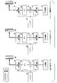
以下、図面を参照し、本発明の車両システム及びハイブリッド車両の実施形態について説明する。図1は、実施形態のハイブリッド車両(以下、HV車両)10の一例を示す構成図である。HV車両10は、回転電機及び内燃機関を備え、車両の走行状態に応じて回転電機及び/又は内燃機関の駆動力によって走行する。一般に、HV車両には、シリーズ方式のものと、パラレル方式のものと、両方式を切り替え可能なものとがある。シリーズ方式のHV車両は、回転電機の動力によって走行する。一方、パラレル方式のHV車両は、回転電機及び内燃機関のいずれか一方又は双方の駆動力によって走行する。HV車両10は、駆動力の伝達系統をシリーズ方式及びパラレル方式のいずれかの構成に切り替え可能なHV車両である。HV車両10は、シリーズ方式及びパラレル方式のいずれかであり、両者の切り替えができないHV車両でもよい。 Hereinafter, embodiments of a vehicle system and a hybrid vehicle according to the present invention will be described with reference to the drawings. FIG. 1 is a configuration diagram showing an example of a hybrid vehicle (hereinafter referred to as HV vehicle) 10 of the embodiment. The
HV車両10は、内燃機関12と、第1回転電機14と、第2回転電機16と、ロックアップクラッチ(以下、クラッチ)18と、ギアボックス(以下、ギア)20と、バッテリ30と、VCU(Voltage Control Unit)32と、第1インバータ34と、第2インバータ36と、車両センサ40と、バッテリセンサ42と、回転数センサ44と、加速度センサ46と、室内温度センサ48と、室外温度センサ50と、車両システム100と、切替スイッチ400と、を備える。車両システム100は、HV車両10に搭載されており、ECU(Electronic Control Unit)200と、表示システム300と、を備える。なお、図1中の太い実線は機械連結を示し、二重点線は電力配線を示し、細い実線の矢印は制御信号又は検出信号を示す。 The
内燃機関12は、クラッチ18が切断された状態で、第2回転電機16を発電機として駆動する。クラッチ18が締結されると、内燃機関12が出力した動力は、HV車両10が走行するための機械エネルギーとして、第2回転電機16、クラッチ18、ギア20、第1回転電機14、ディファレンシャルギヤ60及び車軸62を介して、駆動輪80,80に伝達される。 The
第1回転電機14は、回転子が第2回転電機16及びバッテリ30の少なくとも一方からの電力供給によって電動機として動作し、HV車両10が走行するための動力を発生する。第1回転電機14は、ディファレンシャルギヤ60及び車軸62に接続される。第1回転電機14で発生したトルクは、ディファレンシャルギヤ60及び車軸62を介して、駆動輪80,80に伝達される。また、第1回転電機14は、車両の制動時には発電機として動作し得る。第2回転電機16は、内燃機関12の動力によって駆動され、電力を発生する。 The rotor of the first rotating
クラッチ18は、ECU200からの指示に応じて、内燃機関12から駆動輪80,80までの動力の伝達経路を切断又は締結する。クラッチ18が切断状態であれば、内燃機関12が出力した動力は駆動輪80,80に伝達されず、クラッチ18が接続状態であれば、内燃機関12が出力した動力は駆動輪80,80に伝達される。ギア20は、変速段又は固定段を含む。ギア20は、内燃機関12からの動力を所定の変速比で変速して駆動輪80,80に伝達する。ギア20における変速比は、ECU200からの指示に応じて変更される。 The
バッテリ30は、直列に接続された複数の蓄電セルを有し、例えば100~400Vの高電圧を供給する。蓄電セルは、例えば、リチウムイオン電池やニッケル水素電池である。バッテリ30は、HV車両10を走行させるため、第1回転電機14に走行用の電力を供給する蓄電池(二次電池)である。 The
VCU32は、第1回転電機14が電動機として動作する際のバッテリ30の出力電圧を昇圧する。VCU32は、HV車両10の制動時に第1回転電機14が発電して直流に変換された回生電力をバッテリ30に充電する場合に、第1回転電機14の出力電圧を降圧する。VCU32は、内燃機関12の駆動によって第2回転電機16が発電して直流に変換された電力を降圧する。VCU32によって降圧された電力は、バッテリ30に充電される。 The
VCU32は、バッテリ30が出力する電圧を入力電圧として2つのスイッチング素子をオンオフ切換動作することによって、出力側の電圧をバッテリ30が出力する電圧よりも高い電圧に昇圧する。なお、VCU32の2つのスイッチング素子がオンオフ切換動作しないときの出力側の電圧はバッテリ30が出力する電圧に等しい。
第1インバータ34は、直流電圧を交流電圧に変換して3相電流を第1回転電機14に供給する。また、第1インバータ34は、HV車両10の制動時に第1回転電機14が発電した交流電圧を直流電圧に変換する。第2インバータ36は、内燃機関12の駆動によって第2回転電機16が発電した交流電圧を直流電圧に変換する。 The
車両センサ40は、例えば、アクセル開度センサと、車速センサと、ブレーキ踏量センサと、を備える。アクセル開度センサは、運転者による加速指示を受け付けるアクセルペダルに取り付けられ、アクセルペダルの操作量を検出し、アクセル開度としてECU200に出力する。車速センサは、例えば、各車輪に取り付けられた車輪速センサと速度計算機とを備え、車輪速センサにより検出された車輪速を統合して車両の速度(車速)を導出し、ECU200に出力する。ブレーキ踏量センサは、ブレーキペダルに取り付けられ、ブレーキペダルの操作量を検出し、ブレーキ踏量としてECU200に出力する。 The vehicle sensor 40 includes, for example, an accelerator opening sensor, a vehicle speed sensor, and a brake depression amount sensor. The accelerator opening sensor is attached to an accelerator pedal that receives an acceleration instruction from the driver, detects the operation amount of the accelerator pedal, and outputs it to the
バッテリセンサ42は、例えば、電流センサと、電圧センサと、温度センサと、を備える。電流センサは、バッテリ30の電流値を検出する。電圧センサは、バッテリ30の電圧値を検出する。温度センサは、バッテリ30の温度を検出する。バッテリセンサ42は、検出した電流値、電圧値、温度等をECU200に出力する。
回転数センサ44は、内燃機関12の回転数を検出する。回転数センサ44は、検出した内燃機関12の回転数をECU200に出力する。加速度センサ46は、HV車両10の加速度を検出する。加速度センサ46は、検出したHV車両の加速度をECU200に出力する。 A rotation speed sensor 44 detects the rotation speed of the
室内温度センサ48は、例えば、HV車両10の車室内に設けられる。室内温度センサ48は、HV車両10の室内温度を検出する。室内温度センサ48は、検出した室内温度をECU200に出力する。室外温度センサ50は、例えば、HV車両10の車室外に設けられる。室外温度センサ50は、HV車両10の室外温度を検出する。室外温度センサ50は、検出した室外温度をECU200に出力する。 The
ECU200は、導出部210と、算出部220と、切替部230と、判定部240と、制御部250と、を備える。導出部210、算出部220、切替部230、判定部240、及び制御部250は、例えば、CPU(Central Processing Unit)などのハードウェアプロセッサがプログラム(ソフトウェア)を実行することにより実現される。これらの構成要素のうち一部または全部は、LSI(Large Scale Integration)やASIC(Application Specific Integrated Circuit)、FPGA(Field-Programmable Gate Array)、GPU(Graphics Processing Unit)などのハードウェア(回路部;circuitryを含む)によって実現されてもよいし、ソフトウェアとハードウェアの協働によって実現されてもよい。プログラムは、予めHDD(Hard Disk Drive)やフラッシュメモリなどの記憶装置(非一過性記憶媒体)に格納されていてもよいし、DVDやCD-ROMなどの着脱可能な記憶媒体(非一過性記憶媒体)に格納されており、記憶媒体がドライブ装置に装着されることでインストールされてもよい。 The
ECU200は、HV車両10の状態に応じて、VCU32、第1インバータ34、及び第2インバータ36の制御、並びに、クラッチ18の断接及び内燃機関12の運転の制御を行う。ECU200は、バッテリセンサ42により出力されるバッテリ30の電流値、電圧値、及び温度等のバッテリ情報を入力して取得する。ECU200は、車両センサ40により出力されるアクセル開度、車速、ブレーキ踏量を入力して取得する。ECU200は、回転数センサ44により出力される内燃機関12の回転数及び加速度センサ46により出力されたHV車両10の前後加速度を入力して取得する。ECU200は、室内温度センサ48及び室外温度センサ50により出力される室内温度及び室外温度を入力して取得する。 The
導出部210は、車両センサ40により出力されたアクセル開度、車速、及びブレーキ踏量に基づいて、HV車両10への要求駆動力を示す値を導出する。導出部210は、導出した要求駆動力を切替部230及び制御部250に出力する。 The deriving
算出部220は、バッテリセンサ42により出力されたバッテリ情報に基づいて、バッテリ30の充電率(State Of Charge、以下、SOC)、バッテリ30に入力される充電電力、及びバッテリ30が出力する放電電力を算出する。算出部220は、算出したバッテリ30のSOCを判定部240及び表示制御部310に出力する。算出部220は、算出したバッテリ30に入力される充電電力を示す値及びバッテリ30が出力する放電電力を示す値を制御部250に出力する。 The
切替部230は、導出部210により出力された要求駆動力等に基づいて、車両が走行する際の走行モードを選択して切り替える。走行モードには、典型的に電力走行モードと、エンジン稼働走行モードがある。電力走行モードは、HV車両10が内燃機関を稼働させず蓄電池から供給される電力のみを用いて第1回転電機14の動力によって走行するモードである。エンジン稼働走行モードは、HV車両10が内燃機関12の動力を稼働させて走行するモードである。エンジン稼働走行モードには、シリーズ走行モードと、エンジン直結走行モードがある。シリーズ走行モードは、内燃機関12の運転によって第2回転電機16を回転させ、バッテリ30から供給される電力と合わせて第1回転電機14を駆動させるモードである。エンジン直結走行モードは、クラッチ18を締結させ、内燃機関12が出力した動力によって走行するモードである。以下、各走行モードにおけるクラッチCLの接続関係、動力及び電力の伝達について図2を参照して説明する。 The
図2に示すように、電力走行モードに設定されたHV車両10では、クラッチ18は開放され、内燃機関12は停止している。電力走行モードに設定されたHV車両10は、バッテリ30からの電力供給によって駆動する第1回転電機14の動力によって走行する。 As shown in FIG. 2, in the
シリーズ走行モードに設定されたHV車両10では、クラッチ18は開放され、内燃機関12は運転している。シリーズ走行モードに設定されたHV車両10は、バッテリ30からの電力供給とともに、内燃機関12の運転によって第2回転電機16が発電した電力が供給される第1回転電機14の動力によって走行する。 In the
エンジン直結走行モードに設定されたHV車両10では、クラッチ18は締結され、内燃機関12は運転している。エンジン直結走行モードに設定されたHV車両10は、内燃機関12が出力した動力によって走行する。エンジン直結走行モードでの走行時、第1回転電機14及び第2回転電機16の各回転子は、内燃機関12の駆動とともに連れまわされる。ECU200は、第1回転電機14及び第2回転電機16がそれぞれ無負荷状態となるようにゼロトルク制御を行う。 In the
切替部230は、運転者の指示に基づいて、走行モードを選択するための条件となる選択モードを切り替える。選択モードには、第1モードとしての通常モードと第2モードとしての電力優先モードがある。通常モードは、要求駆動力の増加に応じて電力走行モードからエンジン稼働走行モードに移行させるモードである。通常モードでは、駆動力の増加に応じてHV車両10の走行モードを電力走行モードからエンジン稼働走行モードに切り替え、HV車両10の走行をバッテリ30から供給される電力のみで走行する電力走行から内燃機関12を稼働させて走行するエンジン稼働走行に切り替える。電力優先モードは、エンジン稼働走行モードと同様に、要求駆動力の増加に応じて電力走行モードからエンジン稼働走行モードに移行させるが、通常モードよりも電力走行モードを優先させるモードである。電力優先モードでは、通常モードよりもHV車両10の走行として電力走行を優先させる。
切替部230は、例えば、要求駆動力が所定の第1切替駆動力を超える場合に、走行モードをエンジン稼働走行モードに設定し、所定の第2走行切替駆動力以下の場合に、走行モードを電力走行モードに設定する。第1切替駆動力は、第2切替駆動力より大きい駆動力である。切替部230は、例えば、第2切替駆動力を超えて第1切替駆動力以下であり、選択モードが電力優先モードである場合には、走行モードを電力走行モードに設定する。切替部230は、例えば、第2切替駆動力を超えて第1切替駆動力以下であり、選択モードが通常モードである場合には、走行モードを電力走行モードとはせずにエンジン稼働走行モードに設定する。切替部230は、選択した走行モードを制御部250及び表示システム300に出力し、設定した選択モードを表示システム300に出力する。 For example, when the required driving force exceeds a predetermined first switching driving force, the
判定部240は、少なくとも算出部220により出力されるSOC及びバッテリセンサ42により出力されるバッテリ30の温度に基づいて、選択モードを電力優先モードに設定できるか否かを逐次判定する。判定部240は、選択モードを電力優先モードに設定できるか否かを判定するにあたり、バッテリ30のSOCに閾値を設定する。判定部240は、10%単位でバッテリ30のSOCの閾値を設定する。判定部240は、10%単位以外でバッテリ30のSOCの閾値を設定してもよい。算出部220により出力されるバッテリ30のSOCが、設定した閾値を超える場合に、判定部240は、選択モードを電力優先モードに設定できると判定する。 Based on at least the SOC output by the
判定部240は、選択モードを電力優先モードに設定できるか否かの判定に用いる閾値を、バッテリ30の温度に基づいて調整する。判定部240は、バッテリ30の温度が高いときには閾値を低くし、バッテリ30の温度が低いときには閾値を高くする。判定部240は、設定した閾値を表示制御部310に出力する。判定部240は、選択モードを電力優先モードに設定できるか否かの判定に用いる閾値を調整するにあたり、バッテリ30の温度に代えてまたは加えて、室内温度センサ48により出力されるHV車両10の室内温度や室外温度センサ50により出力されるHV車両10の室外温度を用いてもよい。あるいは、算出部220において、バッテリ30の劣化度を算出し、算出したバッテリ30の劣化度をバッテリ30の温度に代えてまたは加えて用いてもよい。 Determining
判定部240は、電力優先モードに設定できると判定した場合に、設定許可情報を切替部230に出力する。切替部230は、判定部240により設定許可情報が出力されている場合には、選択モードを通常モードと電力優先モードのいずれにも設定できる。切替部230は、判定部240により設定許可情報が出力されていない場合に、選択モードを通常モードに設定できるが、電力優先モードには設定できない。 If determining
制御部250は、切替部230により出力された走行モード及び導出部210により出力された要求駆動力に基づいて、内燃機関12、クラッチ18、第1インバータ34、及び第2インバータ36の制御を行う。 The
表示システム300における表示制御部310は、ECU200等により出力される各種の情報等に基づく画像を表示部320に表示させる。例えば、表示制御部310は、算出部220により算出されたバッテリ30のSOCに基づくSOC画像を表示部320に表示させる。表示制御部310は、切替部230により出力されたHV車両10の走行モード及び選択モードに関するモード情報画像を表示部320に表示させる。表示制御部310は、判定部240により出力された閾値に関する閾値画像を表示部320に表示させる。 The
表示部320は、例えば、車両の運転席前方のインストルメントパネルに設けられた車速計等の計器類を備えるメータパネル部に配置されている。図3は、表示部320に表示される画像の一例を示す図である。図3に示すように、表示部320の左端部には、SOC画像P1が表示される。表示部320におけるSOC画像P1の右側には、走行モード画像PL及び選択モード画像PSが上下に並んで配置されて表示される。その他、表示部320には、メッセージ画像PM、デジタル車速画像PP、メータ画像PE、及び燃料計画像PF等が表示される。 The
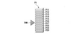
SOC画像P1は、バッテリ30のSOCを表示するグラフの画像である。バッテリ30のSOCを表示するグラフは、棒グラフ様のグラフである。SOC画像P1には、図4に示すように、複数、ここでは10個の第1セグメント画像P11~第10セグメント画像P20が含まれる。第1セグメント画像P11~第10セグメント画像P20は、上下に整列して表示される。第1セグメント画像P11~第10セグメント画像P20は、バッテリ30のSOCに基づいて、明表示または暗表示とされる。 The SOC image P<b>1 is an image of a graph displaying the SOC of the
表示制御部310は、第1セグメント画像P11~第10セグメント画像P20は、10%を単位として、バッテリ30のSOCを表すようにそれぞれ明表示または暗表示させる。例えば、バッテリ30のSOCが10%であるときには、表示制御部310は、第1セグメント画像P11を明表示させ、第2セグメント画像P12~第10セグメント画像P20を暗表示させる。表示制御部310は、この状態から、バッテリ30のSOCが10%増えるごとに明表示されるセグメント画像を下から順に1つずつ増やし、バッテリ30のSOCが100%であるときに、第1セグメント画像P11~第10セグメント画像P20を全て明表示させる。図3及び図4に示す例では、表示部320には、バッテリ30のSOCは90%である状態が示されており、第1セグメント画像P11~第9セグメント画像P19が明表示され、第10セグメント画像P20は暗表示されている。 The
表示制御部310は、判定部240により出力された閾値を、SOC画像P1の表示形態の切り替わり部分で表す画像を、表示部320に表示させる。表示制御部310は、明表示されるセグメント画像PX(X=11~20のいずれか)のうち、SOC画像P1の表示形態の切り替わり部分の上側と下側のセグメント画像PXで表示する色を異ならせる。表示制御部310は、例えば、バッテリ30のSOCが90%、判定部240により表示システム300に出力された閾値が40%である場合に、第1セグメント画像P11~第9セグメント画像P19を明表示させる。表示制御部310は、明表示させる第1セグメント画像P11~第9セグメント画像P19のうち、閾値以下の領域を示す第1セグメント画像P11~第4セグメント画像P14を赤色で表示させ、閾値を超える領域を示す第5セグメント画像P15~第9セグメント画像P19を緑色で表示させる。SOC画像P1は、バッテリ30のSOCと、選択モードを電力優先モードに設定できるか否かの判定に用いる閾値と、を認識可能な画像である。SOC画像P1は、閾値画像を含む画像である。表示制御部310は、運転者が切替スイッチ400を操作することによる通常モードや電力優先モードへ切り替え指示の有無に関わらず、SOC画像P1を表示部320に表示させる。 The
表示制御部310は、算出部220により出力されたSOCが判定部240により出力された閾値よりも小さい場合には、明表示させるセグメント画像PXをすべて同一色、例えば赤色で表示させる。セグメント画像PXがすべて同一色の赤色で表示されることにより、選択モードを電力優先モードにすることができない旨が運転者に報知される。 When the SOC output by the
走行モード画像PLは、HV車両10に設定された走行モードを報知するための画像であり、「ENG」の文字と「BAT」の文字を「/」で仕切った画像である。表示制御部310は、走行モード画像PLのうち、「ENG」の文字と「BAT」の文字の一方を明表示し、他方を暗表示するか、または両方を明表示とする。 The driving mode image PL is an image for notifying the driving mode set to the
選択モード画像PSは、「EV優先」の文字の画像である。表示制御部310は、HV車両10に設定された選択モードが電力優先モードであるときには、「EV優先」の文字を表示部320に明表示させ、通常モードであるときには、「EV優先」の文字を暗表示させる。表示制御部310は、「EV優先」の文字を表示部320に明表示させることにより、HV車両10の選択モードが電力優先モードであることを運転者に報知する。 The selection mode image PS is an image of characters "EV Priority". The
メッセージ画像PMは、運転者に知らせるためのメッセージを含む画像である。表示制御部310は、運転者に知らせる情報をメッセージ画像PMとして表示部320に表示させる。表示制御部310は、例えば、運転者によりHV車両10の走行モードとして電力走行モードが選択され、判定部240により設定許可情報が出力されたときに、「バッテリを優先的に使用します」といった文字を含むメッセージ画像PMを表示部320に表示させる。 The message image PM is an image containing a message to inform the driver. The
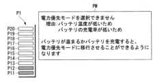
表示制御部310は、判定部240により出力された閾値が算出部220により出力されたSOCよりも大きい場合には、図5に示すように、明表示させるセグメント画像PXをすべて同一色、例えば赤色で表示させることがある。また、判定部240により電力優先モードが許可されないと判定された場合において、運転者が電力優先モードを選択したとき、表示制御部310は、メッセージ画像PMとして、選択モードを電力優先モードに設定できない旨及びその理由を示す文字画像(以下、理由画像)を表示部320に表示させる。表示制御部310は、理由画像を一定の表示時間表示し、表示時間が経過した後に消去する。さらに、表示制御部310は、電力優先モードを設定できるようにする解決策を示す文字画像をメッセージ画像PMに含ませて表示部320に表示させる。 When the threshold output by the
デジタル車速画像PPは、HV車両10の車速をデジタル数字で示す画像である。メータ画像PEは、内燃機関12に関する状態、例えば内燃機関12の回転数に関する情報や図示しない冷却水の温度に関する情報等を示す画像である。燃料計画像PFは、内燃機関12の作動に用いる燃料(ガソリン)の残量を示す画像である。 The digital vehicle speed image PP is an image showing the vehicle speed of the
切替スイッチ400は、選択モードを電力優先モードと通常モードの間で移行させるためのスイッチである。切替スイッチ400は、例えば、インストルメントパネルに設けられたメータパネル部の近傍であり、運転者の手が届く位置に配置されている。切替スイッチ400が操作されると、切替スイッチ400から車両システム100に切替指示が出力される。車両システム100のECU200における切替部230は、切替スイッチ400により出力された切替指示を入力して取得したときに、選択モードを電力優先モードと通常モードとの間で切り替える運転者の指示を取得する。 The
HV車両10は、図示しない充電口や充電コンバータを備えており、HV車両10の外部に備えられた充電器に対して、充電ケーブルを介して接続可能とされている。HV車両10に設けられたバッテリ30は、HV車両10の外部の充電器により供給される電気を誘電可能とされている。HV車両10の外部の充電器により供給される電気は、充電コンバータにより調圧される。HV車両10は、外部の充電器により充電可能とされたいわゆるプラグインハイブリッド車両である。 The
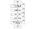
次に、車両システム100における処理について説明する。図6は、車両システム100において実行される処理の流れの一例を示すフローチャートである。車両システム100は、ECU200の導出部210において、車両センサ40により出力されたHV車両10のアクセル開度、車速、及びブレーキ踏量を入力して取得する(ステップS101)。導出部210は、取得したアクセル開度、車速、及びブレーキ踏量に基づいて、要求駆動力を導出する(ステップS103)。 Next, processing in
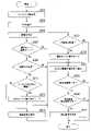
続いて、切替部230は、選択モードの設定を行う(ステップS105)。ここで、図7を参照して、選択モードの設定処理について説明する。選択モードの設定が行われた後、算出部220は、図7に示すように、バッテリセンサ42により出力されるバッテリ30の電流値、電圧値、及び温度等のバッテリ情報を入力して取得する(ステップS201)。 Subsequently, the
続いて、算出部220は、取得したバッテリ30のバッテリ情報に基づいて、バッテリ30のSOCを算出する(ステップS203)。その後、判定部240は、選択モードを電力優先モードに切替できるようにするためのバッテリ30のSOCの閾値を設定する(ステップS205)。バッテリ30のSOCの閾値を設定するにあたり、判定部240は、バッテリ情報に含まれるバッテリ30の温度を参照し、バッテリ30の温度に基づいて、閾値を調整する。 Subsequently, the
バッテリ30は、SOCが所定量未満であると、性能劣化等の観点から、大量の電力を供給することが難しくなる。また、バッテリ30は、SOCが所定量以上であったとしても、その温度が低いときには、やはり性能劣化等の観点から大量の電力を供給することが難しくなる。このため、例えば、バッテリ30のSOCと温度の関係において、電力走行モードとしてよい領域が認められる。 If the SOC of the
図8は、バッテリ30のSOCと温度との関係の一例を示す図である。図8は、バッテリ30のSOCと温度との関係に対して、電力走行モードとしてもよい領域の一例を示す。例えば、図8に示す切替線K1を境に、選択モードを電力優先モードに切り替えることができるバッテリ30のSOCと温度との関係が規定されている。切替線K1は、バッテリ30の温度が低いときにはバッテリ30の温度の上昇に伴ってバッテリ30のSOCが低下し、バッテリ30の温度がある第1変化温度TC1を超えると、バッテリ30の温度の上昇に伴ってバッテリ30のSOCも上昇し、第2変化温度TC2を超えると、バッテリ30のSOCが急激に立ち上がる形状をなす。バッテリ30の劣化は、切替線K1の内側の第1領域R1において相対的に小さくなり、切替線K1の外側の第2領域R2において相対的に大きくなる。なお、切替線K1の内側の第1領域R1とは、バッテリ30のSOCに対するバッテリ30の温度が、バッテリ30の温度が第1変化温度TC1以下の領域において、切替線K1に示す関係よりも大きくなり、バッテリ30の温度が第1変化温度TC1を超える領域において、切替線K1に示す関係よりも小さくなる領域である。バッテリ30の劣化は、切替線K1の内側の第1領域R1では、切替線K1から遠ざかるほど小さくなる傾向がみられ、切替線K1の外側の第2領域R2では、切替線K1から遠ざかるほど大きくなる傾向がみられる。 FIG. 8 is a diagram showing an example of the relationship between the SOC of
このため、バッテリ30から大量に電力を供給してもバッテリ30の劣化が比較的大きくなくなるバッテリ30のSOCは、バッテリ30の温度によって変動する。図8に示す場合、第1変化温度TC1以下の領域において、例えば、バッテリ30のSOCの閾値が60%となるときのバッテリ30の温度を第1温度T1とし、バッテリ30のSOCの閾値が10%となるときのバッテリ30の温度を第2温度T2とする。この場合、第1温度T1よりも高い第2温度T2の場合のバッテリ30のSOCの閾値は10%であり、バッテリ30の温度が第1温度T1である場合のSOCの閾値である60%よりも低くなる。このように、第1変化温度TC1以下の領域では、バッテリ30の温度が高い場合にバッテリ30のSOCの閾値が低くなるが、第1変化温度TC1を超え、第2変化温度TC2以下の領域ではバッテリ30の温度が低い場合にバッテリ30のSOCの閾値が低くなる。このため、バッテリ30の温度に基づいて、選択モードを電力優先モードに切替できるようにするためのバッテリ30のSOCの閾値を設定することができる。この場合、バッテリ30のSOCが低い領域、例えば、バッテリ30のSOCが10%以下の領域では、限られた温度範囲にのみ第1領域R1が存在するので、バッテリ30のSOCの閾値が10%以下となることは稀となる。なお、第2変化温度TC2を超える領域では、ほぼ切替線K1の外側の第2領域R2となるので、バッテリ30のSOCの閾値を100%に設定し、実質的に選択モードを電力優先モードに切り替えられないようにする。また、図8では、バッテリ30のSOCと温度の関係により閾値を設定しているが、バッテリ30のSOCと冷却水温の関係により閾値を設定してもよい。あるいは、バッテリ30のSOC並びにバッテリ30の温度及び冷却水温の関係により閾値を設定してもよい。 Therefore, the SOC of the
続いて、判定部240は、HV車両10に設定された現在の選択モードが通常モードであるか否かを判定する(ステップS207)。なお、HV車両10を起動した際の選択モードとしては、バッテリ30の充電率、温度、及びHV車両10の停止時の選択モード等の要素により、電力優先モード又は通常モードが適宜選択される。選択モードが通常モードであると判定した場合、切替部230は、切替スイッチ400により出力された、選択モードを通常モードから電力優先モードに切り替える切替指示を取得したか否かを判定する(ステップS209)。 Subsequently,
選択モードを通常モードから電力優先モードに切り替える切替指示を取得したと判定した場合、判定部240は、バッテリ30のSOCが閾値を超えるか否かを判定する(ステップS211)。バッテリ30のSOCが閾値を超えると判定した場合、判定部240は、設定許可情報を切替部230に出力する。切替部230は、判定部240により出力された設定許可情報に基づいて、選択モードを通常モードから電力優先モードに切り替えて(ステップS213)、ステップS221に進む。 When determining that the switching instruction to switch the selected mode from the normal mode to the power priority mode is obtained, the
ステップS209において、選択モードを通常モードから電力優先モードに切り替える切替指示を取得していないと判定した場合、切替部230は、そのままステップS221に進む。ステップS211において、バッテリ30のSOCが閾値を超えないと判定部240が判定した場合、電力優先モードへの切替が不可となっている。この場合、表示制御部310は、理由画像を表示部320に表示させて(ステップS215)、ステップS221に進む。 If it is determined in step S209 that a switching instruction for switching the selected mode from the normal mode to the power priority mode has not been obtained, the
判定部240は、ステップS207において、選択モードが通常モードではなく電力優先モードであると判定した場合、切替スイッチ400により出力された切替指示を取得したか否かを判定する(ステップS217)。切替スイッチ400により出力された切替指示を取得したと判定した場合、判定部240は、選択モードを電力優先モードから通常モードに切り替えて(ステップS219)、ステップS221に進む。切替スイッチ400により出力された切替指示を取得していないと判定した場合、判定部240は、そのままステップS221に進む。 If the
続いて、表示制御部310は、算出部220により出力されるSOC及び判定部240により出力される閾値に基づいて、SOC画像P1を表示させるための情報を生成し、SOC画像P1を表示部320に表示させる(ステップS221)。表示制御部310は、出力されるSOCに基づいて、SOC画像P1のうち、明表示させるセグメント画像PXと、暗表示させるセグメント画像PXを決定する。表示制御部310は、出力される閾値に基づいて、明表示させるセグメントの色を決定する。 Subsequently, the
続いて、表示制御部310は、ステップS215において表示される理由画像が表示中であるか否かを判定する(ステップS223)。理由画像が表示中でないと判定した場合、車両システム100は、図7に示す処理を終了する。理由画像が表示中であると判定した場合、表示制御部310は、その画像を表示してから一定の表示時間が経過したか否かを判定する(ステップS225)。表示時間経過していないと判定した場合、表示制御部310は、ステップS225の処理を繰り返す。表示時間経過したと判定した場合、表示制御部310は、理由画像を消去して(ステップS227)、車両システム100は、図7に示す処理を終了する。 Subsequently,
図6に示すフローに戻り、切替部230は、HV車両10の現在の走行モード、ステップS103において算出した要求駆動力及びステップS105で設定した選択モードに基づいて、HV車両10の走行モードを設定する(ステップS107)。切替部230は、例えば、要求駆動力が所定の第1切替駆動力を超える場合に、走行モードをエンジン稼働走行モード(シリーズ走行モードまたはエンジン直結走行モード)に設定する。切替部230は、要求駆動力が第2切替駆動力を超えて第1切替駆動力以下であり、選択モードが電力優先モードである場合には、走行モードを電力走行モードに設定する。 Returning to the flow shown in FIG. 6, the
続いて、制御部250は、ステップS105において算出した要求駆動力及びステップS107で設定した走行モードに基づいて、HV車両10の内燃機関12、クラッチ18、第1インバータ34、及び第2インバータ36の制御を行う(ステップS109)。こうして、車両システム100は、図6に示す処理を終了する。 Subsequently, the
実施形態に係る車両システム100は、HV車両10を、内燃機関12を稼働させて走行するエンジン稼働走行モードと、第1回転電機14によって走行する電力走行モードに走行モードを設定する。車両システム100では、運転者の指示により、通常モードと、通常モードよりも電力走行モードによる電力走行を優先させる電力優先モードを切替可能である。車両システム100は、電力優先モードへの切替を可能とするバッテリ30のSOCの閾値を設定しており、バッテリ30のSOCがその閾値を超える場合に、運転者の指示による電力優先モードへの切替を可能とする。ここで、車両システム100では、電力優先モードへの切替を可能とするバッテリ30のSOCの閾値を表示制御部310が表示部320に表示させている。バッテリ30のSOCの閾値は、バッテリ30の温度に基づいて調整され、電力優先モードへの切替の可否は、バッテリ30のSOC及び温度に基づいて判定されている。このため、適切な電力優先モードへの切替の可否を運転者に知らせることができるので、運転者の利便性を向上させることができる。 The
次に、SOC画像P1の変形例を説明する。図9~図11は、SOC画像P1の変形例を示す図である。図9~図11に示すSOC画像P1の変形例は、いずれも第1セグメント画像P11~第10セグメント画像P20の表示については、上記実施形態と同様であるが、閾値に関する表示が異なる。 Next, a modified example of the SOC image P1 will be described. 9 to 11 are diagrams showing modified examples of the SOC image P1. The modified examples of the SOC image P1 shown in FIGS. 9 to 11 are similar to the above-described embodiment in terms of the display of the first segment image P11 to the tenth segment image P20, but differ in the display of the threshold value.
図9に示す変形例では、表示制御部310は、判定部240により出力される閾値に基づく閾値線THLを表示部320に表示させる。表示制御部310は、SOC画像P1における上記実施形態の切り替わり部分に相当する位置、換言すれば電力優先モードへの切替が可能となるSOCを示す位置に閾値線THLを表示させる。このため、電力優先モードへの切替が可能である場合には、明表示されたセグメント画像PXが閾値線THLよりも上方にあることになる。電力優先モードへの切替が可能でない場合には、閾値線THLよりも上方のセグメント画像PXは、すべて暗表示されることになり、閾値線THLよりも上方のセグメント画像PXは、明表示される場合と暗表示される場合とがある。 In the modification shown in FIG. 9 , the
図10に示す変形例では、表示制御部310は、判定部240により出力される閾値に基づく閾値矢印THMを表示部320に表示させる。表示制御部310は、SOC画像P1における上記実施形態の切り替わり部分に相当する位置を指し占める閾値矢印THMを表示させる。 In the modification shown in FIG. 10 , the
図11に示す変形例では、表示制御部310は、判定部240により出力される閾値に基づく上向矢印THU及び下向矢印THDを表示部320に表示させる。表示制御部310は、SOC画像P1における上記実施形態の切り替わり部分に相当する位置を境として、その上方に上向矢印THUを表示させ、その下方に下向矢印THDを表示させる。これらの表示によっても、電力優先モードへの切替の可否を運転者に知らせることができ、利便性を向上させることができる。 In the modified example shown in FIG. 11 , the
上記実施形態において、SOC画像P1を示すグラフは、棒グラフ様であるが、他の態様でもよく、例えば円グラフ様でもよいし、折れ線グラフ様でもよい。上記実施形態では、SOC画像P1において、切り替わり部分の上側と下側のセグメント画像PXで表示する色を異ならせるが、他の態様としてもよい。例えば、切り替わり部分の上側のセグメント画像PXを強調表示し、下側のセグメント画像PXを通常表示としてもよい。このように、切り替わり部分を境としてセグメント画像PXの輝度や明度を調整してもよい。あるいは、切り替わり部分を境としてセグメント画像PXの形や大きさを変えるようにしてもよい。 In the above embodiment, the graph showing the SOC image P1 is like a bar graph, but it may be in another form, such as a pie graph or a line graph. In the above-described embodiment, in the SOC image P1, the segment images PX above and below the switching portion are displayed in different colors, but other modes may be used. For example, the upper segment image PX of the switching portion may be highlighted and the lower segment image PX may be displayed normally. In this way, the brightness and brightness of the segment image PX may be adjusted using the switching portion as a boundary. Alternatively, the shape and size of the segment image PX may be changed at the switching portion.
上記の実施形態では、電力優先モードへの切替の可否をバッテリ30のSOCと温度に基づいて判定するが、これらに他の要素を用いて参照してもよい。例えば、実施形態で示したHV車両10の室内温度や室外温度などを用いてもよいし、HV車両10に設けられた空調装置などによる負荷を用いてもよい。また、バッテリ30の冷却水温を用いてもよい。なお、バッテリ30の温度はバッテリの冷却水温から推定してもよい。 In the above embodiment, whether or not to switch to the power priority mode is determined based on the SOC and temperature of the
上記の実施形態では、選択モードを電力優先モードに設定できるか否かの判定に用いる閾値をバッテリ30の温度に基づいて調整するが、電力優先モードへの切替の可否の判定を他の態様で行ってもよい。例えば、閾値等を設けることなく、バッテリ30のSOC及び温度の関係と、電力優先モードに設定できるか否かの判定結果とをテーブル化し、このテーブルを参照して電力優先モードへの切替の可否の判定を行ってもよい。あるいは、バッテリ30のSOC及び温度の関係から電力優先モードに設定できるか否かの判定結果を表す演算式を設定し、この演算式を用いて電力優先モードへの切替の可否の判定を行ってもよい。上記実施形態のHV車両10は、プラグインハイブリッド車両であるが、HV車両10は、外部からの充電を受け付けない電動自動車であってもよい。 In the above embodiment, the threshold used to determine whether the selection mode can be set to the power priority mode is adjusted based on the temperature of the
上記実施形態のHV車両10は、電力優先モードは、通常モードと同様に、要求駆動力の増加に応じて電力走行モードからエンジン稼働走行モードに移行させる仕様としているが、移行させない仕様としてもよい。上記実施形態のHV車両10は、エンジン稼働走行モードとして、シリーズ走行モードとエンジン直結走行モードを備えるが、いずれか一方を備えるものでもよい。上記実施形態のHV車両10は、選択モードの切替えを切替スイッチ400により行うものとしたが、運転者の音声を認識する音声認識システムを有し、運転者の音声により、選択モードの切替えを行ってもよい。 In the
以上、本発明を実施するための形態について実施形態を用いて説明したが、本発明はこうした実施形態に何等限定されるものではなく、本発明の要旨を逸脱しない範囲内において種々の変形及び置換を加えることができる。 As described above, the mode for carrying out the present invention has been described using the embodiments, but the present invention is not limited to such embodiments at all, and various modifications and replacements can be made without departing from the scope of the present invention. can be added.
10…HV車両
12…内燃機関
14…第1回転電機
18…クラッチ
20…ギア
30…バッテリ
34…第1インバータ
40…車両センサ
42…バッテリセンサ
62…車軸
80…駆動輪
100…車両システム
210…導出部
220…算出部
230…切替部
240…判定部
250…制御部
310…表示制御部
320…表示部
400…切替スイッチ
P1…SOC画像
P11~P20…第1セグメント画像~第10セグメント画像
Claims (9)
Translated fromJapanese表示部と、
少なくとも前記蓄電池の充電率と、前記蓄電池の温度または冷却水温のうち少なくとも一つが高いほど低く調整された前記充電率に対する閾値と、に基づいて、駆動力の増加に応じて前記内燃機関を稼働させず前記蓄電池により供給される電力のみで前記回転電機を駆動させて走行を行う電力走行から前記内燃機関を稼働させて走行を行うエンジン稼働走行に移行する第1モードから、前記第1モードよりも電力走行を優先させる第2モードへの切替の可否を判定する判定部と、
運転者の指示および前記判定部の判定結果に基づいて、前記第1モードと、前記第2モードと、を切り替える切替部と、
前記第2モードへの切替の可否に関する画像を前記表示部に表示させる表示制御部と、
を備える、車両システム。A vehicle system mounted in a hybrid vehicle comprising an internal combustion engine, a rotating electric machine connected to an axle, and a storage battery for supplying electric power for running to the rotating electric machine,
a display unit;
The internal combustion engine is operated according to the increase inthe driving force based on at least the charging rate of the storage battery and a threshold value for the charging rate that is adjusted lower as at least one of the temperature of the storage battery and the cooling water temperature increases. First, from the first mode in which the electric power running in which the rotating electric machine is driven only by the electric power supplied from the storage battery is shifted to the engine operation running in which the internal combustion engine is operated and the running is performed, than the first mode. a determination unit that determines whether or not to switch to the second mode that prioritizes electric power running;
a switching unit that switches between the first mode and the second mode based on a driver's instruction and a determination result of the determining unit;
a display control unit that causes the display unit to display an image regarding whether or not switching to the second mode is possible;
A vehicle system comprising:
請求項1に記載の車両システム。The display control unit causes the display unit to display an image that allows recognition of the charging rate of the storage battery and the threshold value as an image regarding whether switching to the second mode is possible.
A vehicle system according to claim 1 .
請求項2に記載の車両システム。The threshold value is displayed as a threshold line at a position indicating the charging rate at which switching to the second mode is possible among the charging rates of the storage batteries displayed side by side.
The vehicle system according to claim 2.
請求項1から3のうちいずれか1項に記載の車両システム。The determination unit sequentially determines whether switching tothe second mode is possible,
Vehicle system according to any one ofclaims 1 to 3 .
請求項1から4のうちいずれか1項に記載の車両システム。The display control unit causes the display unit to display an image regarding whether or not switching to the second mode is possible regardless of whether there is an instruction to switch to the second mode.
Vehicle system according to any one ofclaims 1 to 4 .
請求項1から5のうちいずれか1項に記載の車両システム。The display control unit causes the display unit to display an image indicating the reason why switching to the second mode is not possible when switching to the second mode is not possible.
Vehicle system according to any one ofclaims 1 to 5 .
請求項6に記載の車両システム。causing the display unit to display an image indicating the reason why switching to the second mode is impossible only when an instruction to switch to the second mode is given;
Vehicle system according toclaim 6 .
前記セグメント画像のうち明表示されたセグメント画像の色を異ならせて前記閾値を前記表示部に表示させる、displaying the threshold value on the display unit by changing the color of the brightly displayed segment image among the segment images;
請求項1または2に車両システム。A vehicle system according to claim 1 or 2.
Priority Applications (3)
| Application Number | Priority Date | Filing Date | Title |
|---|---|---|---|
| JP2019118985AJP7149230B2 (en) | 2019-06-26 | 2019-06-26 | Vehicle system and hybrid vehicle |
| US16/897,368US11440409B2 (en) | 2019-06-26 | 2020-06-10 | Vehicle system and hybrid vehicle |
| CN202010570724.5ACN112141075B (en) | 2019-06-26 | 2020-06-19 | Vehicle systems and hybrid vehicles |
Applications Claiming Priority (1)
| Application Number | Priority Date | Filing Date | Title |
|---|---|---|---|
| JP2019118985AJP7149230B2 (en) | 2019-06-26 | 2019-06-26 | Vehicle system and hybrid vehicle |
Publications (2)
| Publication Number | Publication Date |
|---|---|
| JP2021003984A JP2021003984A (en) | 2021-01-14 |
| JP7149230B2true JP7149230B2 (en) | 2022-10-06 |
Family
ID=73891142
Family Applications (1)
| Application Number | Title | Priority Date | Filing Date |
|---|---|---|---|
| JP2019118985AActiveJP7149230B2 (en) | 2019-06-26 | 2019-06-26 | Vehicle system and hybrid vehicle |
Country Status (3)
| Country | Link |
|---|---|
| US (1) | US11440409B2 (en) |
| JP (1) | JP7149230B2 (en) |
| CN (1) | CN112141075B (en) |
Families Citing this family (5)
| Publication number | Priority date | Publication date | Assignee | Title |
|---|---|---|---|---|
| DE102019119969A1 (en)* | 2019-07-24 | 2021-01-28 | Volkswagen Aktiengesellschaft | Procedure for displaying a warning message |
| JP7327520B2 (en)* | 2020-01-15 | 2023-08-16 | 三菱自動車工業株式会社 | Vehicle battery operation mode display device |
| CN114981118A (en)* | 2020-01-15 | 2022-08-30 | 三菱自动车工业株式会社 | Battery control device for vehicle |
| JP7177879B2 (en)* | 2021-03-31 | 2022-11-24 | 本田技研工業株式会社 | Vehicle control system and vehicle control method |
| JP7616473B2 (en)* | 2022-02-15 | 2025-01-17 | 三菱自動車工業株式会社 | Support System |
Citations (5)
| Publication number | Priority date | Publication date | Assignee | Title |
|---|---|---|---|---|
| JP2008074321A (en) | 2006-09-25 | 2008-04-03 | Toyota Motor Corp | Hybrid vehicle display device, hybrid vehicle, and hybrid vehicle display method |
| JP2008137543A (en) | 2006-12-04 | 2008-06-19 | Toyota Motor Corp | Vehicle and control method thereof |
| JP2009113706A (en) | 2007-11-08 | 2009-05-28 | Toyota Motor Corp | Hybrid vehicle |
| JP2011230678A (en) | 2010-04-28 | 2011-11-17 | Toyota Motor Corp | Control device for vehicle |
| JP2013119349A (en) | 2011-12-08 | 2013-06-17 | Toyota Motor Corp | Vehicle display device |
Family Cites Families (17)
| Publication number | Priority date | Publication date | Assignee | Title |
|---|---|---|---|---|
| US5433970A (en)* | 1993-10-14 | 1995-07-18 | The Procter & Gamble Company | Process for making high protein and/or reduced fat nut spreads and product thereof which have desirable fluidity, texture and flavor |
| US6766874B2 (en)* | 1998-09-29 | 2004-07-27 | Hitachi, Ltd. | System for driving hybrid vehicle, method thereof and electric power supply system therefor |
| US8676414B2 (en)* | 2007-12-27 | 2014-03-18 | Byd Co. Ltd. | Hybrid vehicle having multi-mode controller |
| JP4386138B1 (en)* | 2008-06-27 | 2009-12-16 | トヨタ自動車株式会社 | Control device and control method for hybrid vehicle |
| US9145048B2 (en)* | 2010-03-31 | 2015-09-29 | General Electric Company | Apparatus for hybrid engine control and method of manufacture same |
| US20130073129A1 (en)* | 2011-09-21 | 2013-03-21 | Ford Global Technologies, Llc | Vehicle display system and method |
| US9440643B1 (en)* | 2015-03-23 | 2016-09-13 | Ford Global Technologies, Llc | Hybrid electric vehicle and method of control |
| KR102737455B1 (en)* | 2015-06-03 | 2024-12-04 | 클리어모션, 아이엔씨. | Methods and systems for controlling vehicle body motion and occupant experience |
| US10107672B2 (en)* | 2016-07-12 | 2018-10-23 | Ford Global Technologies, Llc | Systems and methods for fuel level estimation |
| US10232840B2 (en)* | 2016-08-08 | 2019-03-19 | Ford Global Technologies, Llc | Deceleration control for a hybrid vehicle during towing |
| JP6443694B2 (en)* | 2016-09-07 | 2018-12-26 | トヨタ自動車株式会社 | Vehicle travel control device |
| JP6700164B2 (en)* | 2016-12-19 | 2020-05-27 | トヨタ自動車株式会社 | Control device for hybrid vehicle |
| JP6776975B2 (en)* | 2017-03-29 | 2020-10-28 | トヨタ自動車株式会社 | Car |
| JP6653297B2 (en)* | 2017-08-10 | 2020-02-26 | 本田技研工業株式会社 | Display device |
| JP6620134B2 (en)* | 2017-10-06 | 2019-12-11 | 本田技研工業株式会社 | Hybrid vehicle |
| JP6596480B2 (en)* | 2017-11-29 | 2019-10-23 | 本田技研工業株式会社 | Control device for hybrid vehicle |
| JP2019099012A (en)* | 2017-12-05 | 2019-06-24 | 本田技研工業株式会社 | Vehicle control system, vehicle control method, and program |
- 2019
- 2019-06-26JPJP2019118985Apatent/JP7149230B2/enactiveActive
- 2020
- 2020-06-10USUS16/897,368patent/US11440409B2/enactiveActive
- 2020-06-19CNCN202010570724.5Apatent/CN112141075B/enactiveActive
Patent Citations (5)
| Publication number | Priority date | Publication date | Assignee | Title |
|---|---|---|---|---|
| JP2008074321A (en) | 2006-09-25 | 2008-04-03 | Toyota Motor Corp | Hybrid vehicle display device, hybrid vehicle, and hybrid vehicle display method |
| JP2008137543A (en) | 2006-12-04 | 2008-06-19 | Toyota Motor Corp | Vehicle and control method thereof |
| JP2009113706A (en) | 2007-11-08 | 2009-05-28 | Toyota Motor Corp | Hybrid vehicle |
| JP2011230678A (en) | 2010-04-28 | 2011-11-17 | Toyota Motor Corp | Control device for vehicle |
| JP2013119349A (en) | 2011-12-08 | 2013-06-17 | Toyota Motor Corp | Vehicle display device |
Also Published As
| Publication number | Publication date |
|---|---|
| JP2021003984A (en) | 2021-01-14 |
| US20200406748A1 (en) | 2020-12-31 |
| CN112141075A (en) | 2020-12-29 |
| US11440409B2 (en) | 2022-09-13 |
| CN112141075B (en) | 2024-12-27 |
Similar Documents
| Publication | Publication Date | Title |
|---|---|---|
| JP7149230B2 (en) | Vehicle system and hybrid vehicle | |
| CN110239356B (en) | Vehicle-mounted fuel cell system and control method thereof | |
| CN110799373B (en) | vehicle controls | |
| CN104709278B (en) | Controller for hybrid vehicle | |
| JP6969357B2 (en) | Vehicle hybrid system | |
| JP2005110495A (en) | Display unit used for vehicle having energy storage unit | |
| CN105905118A (en) | State Of Charge Indicator Of Hybrid Vehicle | |
| EP2423064A1 (en) | Vehicle control unit and vehicle control method | |
| US10322714B2 (en) | Hybrid vehicle and control method for same | |
| CN107379968B (en) | display device | |
| CN107399328B (en) | Display device | |
| JP2008211955A (en) | Charge control device for power storage mechanism for traveling | |
| KR20120012654A (en) | Electric vehicle and its control method | |
| JP5407876B2 (en) | Display device for hybrid vehicle | |
| CN110027540B (en) | Control device and control method for hybrid power system of vehicle | |
| JP4977915B2 (en) | Power generation control device | |
| JP4165500B2 (en) | Vehicle control apparatus and vehicle | |
| JP2019199194A (en) | Control device of hybrid vehicle | |
| JP2008174100A (en) | Hybrid vehicle operation state display device | |
| JP5985844B2 (en) | Vehicle control system | |
| CN118790277A (en) | Display control device for vehicle | |
| JP2013158082A (en) | Vehicle and method for controlling vehicle | |
| JP2015217757A (en) | Control device for hybrid vehicle | |
| JP2014065453A (en) | Hybrid-type cargo handling vehicle | |
| JP2008074336A (en) | Hybrid vehicle display control device, display control method, program for realizing display control method by computer, and recording medium recording the program |
Legal Events
| Date | Code | Title | Description |
|---|---|---|---|
| A621 | Written request for application examination | Free format text:JAPANESE INTERMEDIATE CODE: A621 Effective date:20210329 | |
| A977 | Report on retrieval | Free format text:JAPANESE INTERMEDIATE CODE: A971007 Effective date:20220324 | |
| A131 | Notification of reasons for refusal | Free format text:JAPANESE INTERMEDIATE CODE: A131 Effective date:20220325 | |
| A521 | Request for written amendment filed | Free format text:JAPANESE INTERMEDIATE CODE: A523 Effective date:20220517 | |
| TRDD | Decision of grant or rejection written | ||
| A01 | Written decision to grant a patent or to grant a registration (utility model) | Free format text:JAPANESE INTERMEDIATE CODE: A01 Effective date:20220906 | |
| A61 | First payment of annual fees (during grant procedure) | Free format text:JAPANESE INTERMEDIATE CODE: A61 Effective date:20220926 | |
| R150 | Certificate of patent or registration of utility model | Ref document number:7149230 Country of ref document:JP Free format text:JAPANESE INTERMEDIATE CODE: R150 |