JP7147993B2 - SECURITY ASSESSMENT DEVICE, SECURITY ASSESSMENT METHOD, AND PROGRAM - Google Patents
SECURITY ASSESSMENT DEVICE, SECURITY ASSESSMENT METHOD, AND PROGRAMDownload PDFInfo
- Publication number
- JP7147993B2 JP7147993B2JP2021545467AJP2021545467AJP7147993B2JP 7147993 B2JP7147993 B2JP 7147993B2JP 2021545467 AJP2021545467 AJP 2021545467AJP 2021545467 AJP2021545467 AJP 2021545467AJP 7147993 B2JP7147993 B2JP 7147993B2
- Authority
- JP
- Japan
- Prior art keywords
- security assessment
- infected
- rule
- behavior
- list
- Prior art date
- Legal status (The legal status is an assumption and is not a legal conclusion. Google has not performed a legal analysis and makes no representation as to the accuracy of the status listed.)
- Active
Links
Images


Classifications
- G—PHYSICS
- G06—COMPUTING OR CALCULATING; COUNTING
- G06F—ELECTRIC DIGITAL DATA PROCESSING
- G06F21/00—Security arrangements for protecting computers, components thereof, programs or data against unauthorised activity
- G06F21/70—Protecting specific internal or peripheral components, in which the protection of a component leads to protection of the entire computer
- G06F21/71—Protecting specific internal or peripheral components, in which the protection of a component leads to protection of the entire computer to assure secure computing or processing of information
- G06F21/73—Protecting specific internal or peripheral components, in which the protection of a component leads to protection of the entire computer to assure secure computing or processing of information by creating or determining hardware identification, e.g. serial numbers
- G—PHYSICS
- G06—COMPUTING OR CALCULATING; COUNTING
- G06F—ELECTRIC DIGITAL DATA PROCESSING
- G06F21/00—Security arrangements for protecting computers, components thereof, programs or data against unauthorised activity
- G06F21/50—Monitoring users, programs or devices to maintain the integrity of platforms, e.g. of processors, firmware or operating systems
- G06F21/55—Detecting local intrusion or implementing counter-measures
- G06F21/554—Detecting local intrusion or implementing counter-measures involving event detection and direct action
- G—PHYSICS
- G06—COMPUTING OR CALCULATING; COUNTING
- G06F—ELECTRIC DIGITAL DATA PROCESSING
- G06F21/00—Security arrangements for protecting computers, components thereof, programs or data against unauthorised activity
- G06F21/50—Monitoring users, programs or devices to maintain the integrity of platforms, e.g. of processors, firmware or operating systems
- G06F21/57—Certifying or maintaining trusted computer platforms, e.g. secure boots or power-downs, version controls, system software checks, secure updates or assessing vulnerabilities
- G06F21/577—Assessing vulnerabilities and evaluating computer system security
- G—PHYSICS
- G06—COMPUTING OR CALCULATING; COUNTING
- G06F—ELECTRIC DIGITAL DATA PROCESSING
- G06F2221/00—Indexing scheme relating to security arrangements for protecting computers, components thereof, programs or data against unauthorised activity
- G06F2221/03—Indexing scheme relating to G06F21/50, monitoring users, programs or devices to maintain the integrity of platforms
- G06F2221/034—Test or assess a computer or a system
Landscapes
- Engineering & Computer Science (AREA)
- Computer Security & Cryptography (AREA)
- Computer Hardware Design (AREA)
- Theoretical Computer Science (AREA)
- General Engineering & Computer Science (AREA)
- Software Systems (AREA)
- Physics & Mathematics (AREA)
- General Physics & Mathematics (AREA)
- Computing Systems (AREA)
- Mathematical Physics (AREA)
- Testing And Monitoring For Control Systems (AREA)
- Programmable Controllers (AREA)
Description
Translated fromJapanese本開示は、セキュリティアセスメント装置、セキュリティアセスメント方法、非一時的なコンピュータ可読媒体に関する。 The present disclosure relates to a security assessment device, a security assessment method, and a non-transitory computer-readable medium.
特許文献1は、SCADA(Supervisory Control And Data Acquisition)システムのサイバー攻撃を検出するシステムを開示している。
特許文献2は、コンピュータのセキュリティに関し、プログラムの実行フローを変更する攻撃を検出、保護するための方法を開示している。この方法は、制御フロールールを得るために、コードの一部に関して生成された基準制御フローを解析するステップと、基準制御フローからの偏差の検出を容易にするために、コードの一部を実行中に制御フロールールを評価するステップと、を備えている。
PLCを用いた制御システムでは、サイバー攻撃に対するセキュリティリスクを簡便かつ適切に評価することが望まれる。 Control systems using PLCs are desired to easily and appropriately evaluate security risks against cyberattacks.
本開示の目的は、上述した課題を鑑み、セキュリティリスクを簡便かつ適切に評価することができるセキュリティアセスメント装置、セキュリティアセスメント方法及び非一時的なコンピュータ可読媒体を提供することにある。 An object of the present disclosure is to provide a security assessment device, a security assessment method, and a non-transitory computer-readable medium that can easily and appropriately assess security risks in view of the above-described problems.
本開示にかかるセキュリティアセスメント装置は、コントローラを用いて制御される施設のセキュリティアセスメント装置であって、前記施設に設けられた複数の要素に関するデータ、及び前記コントローラの制御プログラムコードに基づいて、前記施設を非安全状態にする感染要素を特定して、感染要素リストを生成する特定部と、前記感染要素リストの中から選択された選択要素の感染振る舞いを生成する感染振る舞い生成部と、を備えている。 A security assessment device according to the present disclosure is a security assessment device for a facility controlled using a controller, wherein the facility is controlled based on data relating to a plurality of elements provided in the facility and control program code of the controller. an identifying unit that identifies infectious elements that make the insecure state, and generates an infected element list; and an infected behavior generating unit that generates infected behavior of selected elements selected from the infectious element list there is
本開示にかかるセキュリティアセスメント方法は、コントローラを用いて制御される施設のセキュリティアセスメント方法であって、前記施設に設けられた複数の要素に関するデータ、及び前記コントローラの制御プログラムコードに基づいて、前記施設を非安全状態にする感染要素を特定するステップと、感染要素リストを生成するステップと、前記感染要素リストの中から選択された選択要素の感染振る舞いを生成する感染振る舞いステップと、を備えている。 A security assessment method according to the present disclosure is a security assessment method for a facility controlled using a controller, wherein the facility is based on data relating to a plurality of elements provided in the facility and control program code of the controller. generating an infected element list; and generating an infected behavior for selected elements selected from the infected element list. .
本開示にかかる非一時的なコンピュータ可読媒体は、コントローラを用いて制御される施設のセキュリティアセスメント方法をコンピュータに対して実施させるプログラムが格納された非一時的なコンピュータ可読媒体であって、セキュリティアセスメント方法は、前記施設に設けられた複数の要素に関するデータ、及び前記コントローラの制御プログラムコードに基づいて、前記施設を非安全状態にする感染要素を特定するステップと、感染要素リストを生成するステップと、前記感染要素リストの中から選択された選択要素の感染振る舞いを生成する感染振る舞いステップと、を備えている。 A non-transitory computer-readable medium according to the present disclosure is a non-transitory computer-readable medium storing a program that causes a computer to perform a security assessment method for facilities controlled using a controller, The method includes the steps of identifying infectious agents that cause the facility to become unsafe based on data regarding a plurality of elements located at the facility and control program code of the controller; and generating an infectious agent list. , an infected behavior step of generating an infected behavior for a selected element selected from the infected element list.
本開示によれば、適切かつ簡便にセキュリティリスクを評価することができるセキュリティアセスメント装置、セキュリティアセスメント方法、及びプログラムを提供することができる。 According to the present disclosure, it is possible to provide a security assessment device, a security assessment method, and a program capable of appropriately and simply evaluating security risks.
以下、図面を参照して本発明の実施の形態について説明する。各図面において、同一又は対応する要素には同一の符号が付されており、説明の明確化のため、必要に応じて重複説明を省略する。 BEST MODE FOR CARRYING OUT THE INVENTION Hereinafter, embodiments of the present invention will be described with reference to the drawings. In each drawing, the same reference numerals are given to the same or corresponding elements, and redundant description will be omitted as necessary for clarity of description.
実施の形態1.
実施の形態にかかるセキュリティアセスメント装置は、ICS(Industrial Control System)におけるセキュリティリスクを評価する。例えば、セキュリティアセスメント装置は、PLC(Programmable Logic Controller)等のコントローラを用いた制御システム、例えば、SCADA(Supervisory Control And Data Acquisition)システムのサイバーセキュリティリスクを評価する。
A security assessment apparatus according to an embodiment evaluates security risks in an ICS (Industrial Control System). For example, the security assessment device evaluates the cyber security risk of a control system using a controller such as a PLC (Programmable Logic Controller), for example, a SCADA (Supervisory Control And Data Acquisition) system.
例えば、プラント、工場、インフラ設備、ビルなどの制御対象施設がPLC(Programmable Logic Controller)等のコントローラを用いて、監視、及び制御される。制御対象施設には、アクチュエータ、センサなどの各種デバイスが複数設けられている。センサは、例えば、水位計、流量計、温度計、圧力計、速度計等であり、測定結果をPLCに出力する。アクチュエータは、バルブやモータなどであり、PLCからコマンドによって動作する。PLCは、センサからの出力に応じて、アクチュエータを制御するコントローラである。具体的には、PLCは、予めプログラムされたPLCコードに従って、アクチュエータに指令を出力することで、制御対象施設を制御する。 For example, facilities to be controlled such as plants, factories, infrastructure facilities, and buildings are monitored and controlled using controllers such as PLCs (Programmable Logic Controllers). A facility to be controlled is equipped with a plurality of various devices such as actuators and sensors. The sensors are, for example, water level gauges, flow meters, thermometers, pressure gauges, speedometers, etc., and output measurement results to the PLC. Actuators are valves, motors, etc., and operate according to commands from the PLC. A PLC is a controller that controls an actuator according to an output from a sensor. Specifically, the PLC controls the facility to be controlled by outputting commands to actuators according to preprogrammed PLC codes.
さらに、制御対象施設には、アクチュエータ、センサのみに限らず、貯水槽や配管などのデータを入力又は出力しない物理的な機器(equipment)が設けられている。センサは、物理的な機器に関する情報(例えば,水位など)を検出する。アクチュエータ及びセンサなどのアクティブな機器と、貯水槽などパッシブな機器とをまとめて要素とする。つまり、要素は、アクチュエータやセンサなどに限らず、データを入出力しない物理的な構成を含む。要素は、センサの検出対象やアクチュエータの制御対象となる物理プロセスの状態を含む。制御対象施設には、各種要素が複数設けられている。 Furthermore, facilities to be controlled include not only actuators and sensors, but also physical equipment such as water tanks and pipes that do not input or output data. Sensors detect information about physical equipment (eg, water level, etc.). Active devices, such as actuators and sensors, and passive devices, such as water tanks, are grouped together as elements. In other words, elements include not only actuators, sensors, and the like, but also physical structures that do not input or output data. Elements include states of physical processes that are detected by sensors and controlled by actuators. A facility to be controlled is provided with a plurality of various elements.
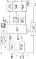
セキュリティアセスメント装置100について、図1を用いて説明する。図1は、セキュリティアセスメント装置100の構成を示す機能ブロック図である。セキュリティアセスメント装置100は、アセスメント管理部11、制御ルール生成部12、物理プロセスルール生成部13、アタックシナリオ生成部14、感染要素特定部15、感染振る舞い生成部16、及びルール記憶部17を備えている。さらに、セキュリティアセスメント装置100は、入力部21と、出力部22とを備えている。 The
入力部21は、ユーザからの入力を受け付けるための入力装置を備えている。入力装置は、例えば、キーボード、マウス、タッチパネルなどである。ユーザは入力装置を操作して、非安全状態、PLCコード、物理データ、設計データ等の入力データを入力する。あるいは、入力部21は、他の装置から送信されたデータを入力データとして取得してもよい。入力部21は、非安全状態、PLCコード、物理データ、設計データをアセスメント管理部11に出力する。 The
PLCコードは、プラント等の制御対象施設を制御するための制御プログラムである。PLCコードに従い、アクチュエータがセンサからの出力に応じた動作を行う。例えば、センサによって検出された貯水槽の水位が少ない場合、PLCコードに従って、バルブが開くことで、貯水槽に水が供給される。センサによって検出された貯水槽の水位が多い場合、PLCコードに従って、バルブが閉じることで、貯水槽への水の供給が停止する。このようにすることで、貯水槽の水位を安全な範囲に保つことができる。非安全状態は、水位などの物理プロセスが、閾値によって規定される安全な範囲に無い状態となる。ユーザは、例えば、貯水槽から水があふれている状態や水が少なすぎる状態を非安全状態として設定することができる。 A PLC code is a control program for controlling a controlled facility such as a plant. According to the PLC code, the actuator operates according to the output from the sensor. For example, when the water level in the reservoir detected by the sensor is low, the valve is opened to supply water to the reservoir according to the PLC code. When the water level in the reservoir detected by the sensor is high, according to the PLC code, the valve closes to stop the water supply to the reservoir. By doing so, the water level in the water tank can be kept within a safe range. An unsafe condition is a condition in which a physical process, such as water level, is not within the safe range defined by the threshold. The user can set, for example, a state in which water is overflowing from the water tank or a state in which there is too little water as an unsafe state.
物理データは、センサ、アクチュエータ等の各種要素に関するデータである。例えば、センサやアクチュエータの種類等である。さらに、物理データは、各センサやアクチュエータに対する入力及び出力に関するデータを含んでいてもよい。設計データは、制御対象施設の全体に関するデータであり、例えば、制御対象施設に設けられている要素の数や配置に関するデータである。 Physical data is data relating to various elements such as sensors and actuators. For example, it is the type of sensor or actuator. In addition, physical data may include data regarding inputs and outputs for each sensor or actuator. The design data is data relating to the entire facility to be controlled, for example, data relating to the number and arrangement of elements provided in the facility to be controlled.
アセスメント管理部11は、制御ルール生成部12~ルール記憶部17の各機能ブロックを全体的に管理する。アセスメント管理部11は、ユーザが入力した非安全状態、PLCコード、及び物理データを取得する。アセスメント管理部11は、ユーザが感染要素のリストの中から選択した選択要素を取得する。アセスメント管理部11は、ユーザからの入力に基づいて、セキュリティ評価を実施して、評価結果としてのアタックシナリオを出力部22に出力する。出力部22は、アタックシナリオをユーザに対して出力するための出力装置を備えている。具体的には、出力部22は、アタックシナリオを表示する表示モニタなどを有している。 The assessment management unit 11 manages the functional blocks from the control
制御ルール生成部12は、アセスメント管理部11からの入力として、PLCコードを取得する。制御ルール生成部12は、PLCコードに基づいて、制御ルール及び状態リストを生成する。制御ルール生成部12は、生成した制御ルール、及び状態リストをルール記憶部17に書き込む。制御ルールは、通常時において、PLCが各アクチュエータを制御するためのルールである。状態リストはアクチュエータ、センサ、コントローラが取り得る状態を列挙したリストである。 The
物理プロセスルール生成部13は、アセスメント管理部11からの入力として、物理データ及び設計データを取得する。物理プロセスルール生成部13は、物理データ及び設計データに基づいて、物理的な機器の状態リスト及び物理プロセスルールを生成する。物理プロセスルール生成部13は、生成した状態リスト及び物理プロセスルールをルール記憶部17に書き込む。物理プロセスルールは、通常時において、各要素の動作を示すルールである。例えば、アクチュエータ、センサの入力と出力とが対応付けられている。状態リストは、アクチュエータ、センサ、パッシブな機器がと取り得る状態を列挙したリストである。 The physical process
通常時における物理プロセスルールと制御ルールとをまとめて通常ルールとする。通常ルールは、非感染時における各要素の通常動作を示すルールとなる。通常ルールでは、入力変数と出力変数とが対応付かられている。状態リスト、及び通常ルールは、要素毎に生成される。 The physical process rule and the control rule in the normal state are collectively referred to as the normal rule. A normal rule is a rule that indicates the normal operation of each element when not infected. In normal rules, input variables and output variables are associated with each other. A state list and normal rules are generated for each element.
感染要素特定部15は、アセスメント管理部11からの入力として、非安全状態及び通常ルールを取得する。感染要素特定部15は、非安全状態の原因となる感染要素を特定して、感染要素リストを生成する。感染要素リストは、非安全状態の原因となる全ての要素を列挙したものである。感染要素特定部15は、入力された非安全状態毎に、感染要素リストを生成する。感染要素特定部15は、生成した感染要素リストをアセスメント管理部11に出力する。 The infectious
アセスメント管理部11は、感染要素リストを出力部22に出力させる。つまり、出力部22は、非安全状態毎の感染要素リストをユーザに対して表示する。ユーザは、入力部21を操作することで、感染要素リストの中から、1つ又は複数の感染要素を選択する。ユーザによって選択された感染要素を選択要素とする。ユーザは、感染要素リストの中から着目したい要素を選択要素として指定する。アセスメント管理部11は、選択要素を感染振る舞い生成部16に出力する。 The assessment management unit 11 causes the
感染振る舞い生成部16は、アセスメント管理部11からの入力として、通常ルール及び状態リストを取得する。さらに、感染振る舞い生成部16が、アセスメント管理部11からの入力として、選択要素を取得する。感染振る舞い生成部16は、通常ルール、及び状態リストに基づいて、選択要素の感染振る舞いを生成する。感染振る舞い生成部16は、感染振る舞いを感染ルールとしてルール記憶部17に書き込む。 The infected
アタックシナリオ生成部14は、アセスメント管理部11からの入力として、感染ルール及び通常ルールを取得する。アタックシナリオ生成部14は、感染ルール及び通常ルールに基づいて、アタックシナリオを生成する。アタックシナリオ生成部14は、ルールに対してモデルチェックを実行することで、非安全状態となるアタックシナリオを生成する。アタックシナリオ生成部14は、アタックシナリオをアセスメント管理部11に出力する。アセスメント管理部11は、アタックシナリオを出力部22に出力させる。出力部22は、ユーザが選択した選択要素に対するアタックシナリオをユーザに対して表示する。 The attack
図2は、セキュリティアセスメント装置100におけるセキュリティアセスメント方法を示すフローチャートである。まず、アセスメント管理部11は、入力として、非安全状態、PLCコード、物理データ、及び設計データを取得する(S11)。 FIG. 2 is a flow chart showing a security assessment method in the
制御ルール生成部12が、制御ルールを生成して、ルール記憶部17に書き込む(S12)。制御ルール生成部12は、PLCコードを参照して、PLCが各アクチュエータを制御するためのルールを制御ルールとして生成する。例えば、制御ルールは、センサでの検出結果と、アクチュエータに送信するコマンドとを対応付けたルールである。制御ルール生成部12は、PLC等の状態リストを生成してもよい。状態リストは、各要素の状態を示すリストである。 The control
物理プロセスルール生成部13が、物理プロセスルールを生成して、ルール記憶部17に書き込む(S13)。物理プロセスルール生成部13は、物理データ、及び設計データを参照して、物理プロセスルールを生成する。物理プロセスルール生成部13は要素毎に物理プロセスルールを生成する。物理プロセスルール生成部13は、物理データ、及び設計データを参照して、アクチュエータ、センサ等の状態リストを生成してもよい。状態リストは、各要素の状態を示すリストである。 The physical process
感染要素特定部15は、感染要素を特定して、感染要素リストをアセスメント管理部11に送信する(S14)。感染要素特定部15が感染要素リストを生成する処理について、図3を用いて説明する。図3は、感染要素リストを生成する処理を示すフローチャートである。 The infectious
まず、感染要素特定部15は、非安全状態を指定する変数を変数V1として設定する(S21)。例えば、貯水槽の水位が閾値を超える状態が非安全状態として入力されている場合、当該貯水槽の水位が変数V1となる。次に、感染要素特定部15は、変数V1の値を変化させる通常ルールRを探索する(S22)。感染要素特定部15は、新しいルールが発見されたか否かを判定する(S23)。新しいルールが発見された場合、新たに発見された通常ルールRにおいて、変数V1の値を変化させる変数V2を探索する(S24)。つまり、感染要素特定部15は、通常ルールを参照して、変数V1に影響を及ぼす変数V2を見つける。感染要素特定部15は、通常ルールにおいて、変数V1に対応付けられている変数V2を見つける。 First, the infectious
感染要素特定部15は、新たに見つかった通常ルールRがアクチュエータ、センサ、又はPLCのルールであるか否かを判定する(S25)。通常ルールRがアクチュエータ、センサ、又はPLCのルールである場合(S25のYES)、感染要素特定部15は、要素名を感染要素リストに追加する(S26)。このように、感染要素特定部15は、通常ルールを参照して、新たな感染要素を特定する。そして、感染要素特定部15は、新たに特定した感染要素を感染要素リストにリストアップする。 The infectious
感染要素特定部15が、感染要素を感染要素リストに追加したら、感染要素特定部15は、変数V2を変数V1に設定する(S27)。また、新たに見つかった通常ルールRがアクチュエータ、センサ、又はPLCのルールでない場合(S25のNO)、感染要素特定部15は、変数V2を変数V1に設定する(S27)。つまり、パッシブな機器はウィルス又は悪意ある振る舞いに感染しないため、新たに探索された通常ルールが、貯水槽などのパッシブな機器の通常ルールである場合、感染要素リストが増加しない。感染要素特定部15は、変数V2を変数V1に設定したら(S27)、S22に戻り、同様の処理を繰り返す。また、S23において、新たな通常ルールが見つからなかった場合、感染要素特定部15は、感染要素リストを、アセスメント管理部11に返す(S28)。つまり、非安全状態の原因となる全ての要素が感染要素として特定されたため、感染要素特定部15の処理が終了する。 After the infectious
このように、感染要素特定部15は、通常ルールを参照して、非安全状態の原因となるセンサ、アクチュエータ、PLCを感染要素として特定する。つまり、感染要素特定部15は、通常ルールにおいて、非安全状態を規定する変数に紐付いている変数を順番に探索していく。これにより、感染要素特定部15は、直接又は間接的に非安全状態の原因となる全ての要素を感染要素として特定することができる。 In this way, the infectious
ユーザが複数の非安全状態を指定した場合、感染要素特定部15は、それぞれの非安全状態に対して、上記の処理を実行する。これにより、感染要素特定部15は、非安全状態毎に感染要素リストを生成することができる。つまり、非安全状態毎に、ステップS21の変数V1が異なるため、独立した感染要素リストが生成される。 When the user designates a plurality of non-safe states, the infectious
図2の説明に戻る。アセスメント管理部11は、ユーザによって選択された選択要素を受け取る(S15)。例えば、ユーザが入力部21を操作することで、表示モニタに表示されている感染要素リストの中から1つ又は複数の感染要素を選択する。アセスメント管理部11は、ユーザによって選択された感染要素を選択要素として受け取る。感染振る舞い生成部16は、選択要素の感染振る舞いの感染ルールを生成する(S16)。感染振る舞い生成部16は、状態リスト及び選択要素の通常ルールを参照して、感染振る舞いを決定する。感染振る舞い生成部16は、感染振る舞いを感染ルールとしてルール記憶部17に書き込む。感染振る舞い生成部16は、選択要素をアセスメント管理部11に送信する。 Returning to the description of FIG. The assessment management unit 11 receives the selection element selected by the user (S15). For example, the user operates the
感染振る舞い生成部16の処理について、図4を用いて説明する。図4は、感染振る舞い生成部16における処理を示すフローチャートである。 Processing of the
感染振る舞い生成部16は、感染要素リストの中の1つの感染要素を選択要素Cとして設定する(S31)。選択要素Cの通常ルールにおいて、変数V3を特定する(S32)。変数V3は、感染要素の出力を変化させる変数である。感染振る舞い生成部16は、変数V3の状態リストを探索する(S33)。感染振る舞い生成部16は、状態リストが見つかったか否かを判定する(S34)。 The
状態リストが見つからなかった場合(S34のNO)、感染要素特定部15は処理を終了する。状態リストが見つかった場合(S34のYES)、感染要素特定部15は、変数V3が任意の値を取ることができるルールを生成して、当該ルールをルール記憶部17に格納する。つまり、感染要素は実際の値とは異なる値を出力するため、感染要素が全ての取り得る値を出力するルールが感染ルールとなる。 If the status list is not found (NO in S34), the infected
感染振る舞い生成部16は、さらに選択要素があるか否かを判定する(S36)。さらに選択要素がある場合(S36のYES)、S31に戻る。上記の処理を次の選択要素に対して実施する。選択要素がない場合(S36のNO)、感染振る舞い生成部16は、処理を終了する。このようにすることで、全ての選択要素に対する感染振る舞いが生成され、感染ルールとして書き込まれる。 The infected
図2の説明に戻る。アタックシナリオ生成部14は、ルール記憶部17に格納されているルールに基づいて、アタックシナリオを生成する(S17)。例えば、非安全状態となるアタックシナリオを生成するために、追加の入力として、その非安全状態がアタックシナリオ生成部14に入力される。アタックシナリオ生成部14は、ルール記憶部17に格納されている感染ルール、及び通常ルールに基づいて、アタックシナリオを生成する。アタックシナリオ生成部14は、ユーザによって指定された要素がウィルス感染等した場合のアタックシナリオを生成する。そして、アセスメント管理部11は、アタックシナリオを表示モニタ上に表示させる(S18)。 Returning to the description of FIG. The attack
このようにすることで、制御対象施設にある要素の感染振る舞いを適切に評価することができる。例えば、外部からのサイバー攻撃によってアクチュエータやセンサがウィルスに感染した場合の制御対象施設全体の振る舞いをユーザが事前に把握することができる。 By doing so, the infection behavior of the elements in the controlled facility can be properly evaluated. For example, the user can grasp in advance the behavior of the entire controlled facility when actuators and sensors are infected with a virus due to a cyberattack from the outside.
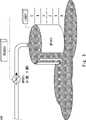
図5はコントローラであるPLCにより制御されるプラントの構成の位置例を示す。プラント200は、貯水槽WT001と、バルブMV001と、センサLS001とを備えている。センサLS001は、貯水槽WT001の水位を測定する。センサLS001は、水位の測定結果をコントローラPLC001に出力する。例えば、センサLS001は、水位を0~5の6段階で出力する。水位が0の時、貯水槽WT001が空になっており、水位が5の時、水が貯水槽WT001からあふれている。センサLS001の出力をLS001.Sとする。 FIG. 5 shows an example of the position of the configuration of the plant controlled by the controller PLC. The
バルブMV001は、貯水槽WT001に供給される水を制御する。バルブMV001が開くと、貯水槽WT001に水が供給され、バルブMV001が閉じると、貯水槽WT001への水の供給が停止する。コントローラPLC001は、センサLS001で測定された貯水槽WT001の推移に応じて、バルブMV001を制御する。バルブMV001が閉じている状態を0、開いている状態を1として示す。 Valve MV001 controls water supplied to water tank WT001. When the valve MV001 is opened, water is supplied to the water tank WT001, and when the valve MV001 is closed, the water supply to the water tank WT001 is stopped. The controller PLC001 controls the valve MV001 according to the transition of the water tank WT001 measured by the sensor LS001. 0 indicates that the valve MV001 is closed, and 1 indicates that it is open.
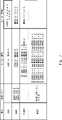
図6は、図5に示すプラント200での状態リスト、及びルールを示す表である。図6の表は、要素、状態リスト、通常ルール、感染ルールのカラムを備えている。つまり、各要素に状態リスト、通常ルール、感染ルールが対応付けられている。 FIG. 6 is a table showing a state list and rules in the
バルブMV001の状態リストには、3種類の状態MV001.A、MV001.S、MV001.Cが格納される。MV001.AはバルブMV001の実際の状態(actual state)を示す。MV001.SはバルブMV001からコントローラPLC001に送信される状態信号を示している。MV001.CはコントローラPLC001からバルブMV001に送信された指令を示している。MV001.A、MV001.S、及びMV001.Cは、それぞれ、0(閉状態)又は1(開状態)の値を取る変数である。このように、アクチュエータであるバルブMV001の状態リストには、実状態、状態信号、及び指令が設定されている。バルブMV001の状態リストは、物理プロセスルール生成部13によって生成されている。 The state list of the valve MV001 stores three types of states MV001.A, MV001.S, and MV001.C. MV001.A indicates the actual state of valve MV001. MV001.S indicates a status signal sent from the valve MV001 to the controller PLC001. MV001.C indicates the command sent from the controller PLC001 to the valve MV001. MV001.A, MV001.S, and MV001.C are variables that take a value of 0 (closed) or 1 (open), respectively. Thus, the actual state, the state signal, and the command are set in the state list of the valve MV001, which is the actuator. The state list of the valve MV001 is generated by the physical
貯水槽WT001の状態リストには、貯水槽WT001の実際の水位(actual water level)を示す状態としてWT001.Aが設定されている。貯水槽WT001の水位は、上記の通り、6段階のレベルに分けられている。貯水槽WT001の実際の水位に応じて、WT001.Aは0~5の値を取る変数である。貯水槽WT001の状態リストは、物理プロセスルール生成部13によって生成された物理プロセスルールである。 In the status list for water tank WT001, WT001.A is set as the status indicating the actual water level of water tank WT001. The water level of the water tank WT001 is divided into six levels as described above. WT001.A is a variable that takes values from 0 to 5, depending on the actual water level in the water tank WT001. The state list of the water tank WT001 is the physical process rule generated by the physical
センサLS001の通常ルールには、LS001.S=WT001.Aとする物理プロセスルールが設定されている。つまり、センサLS001が通常通り動作している場合、センサLS001は、貯水槽WT001の水位の測定結果を出力する。よって、センサLS001の出力LS001.Sが貯水槽WT001の実水位(actual water level)WT001.Aと一致する。センサLS001の通常ルールは、物理プロセスルール生成部13によって生成された物理プロセスルールである。 A physical process rule of LS001.S=WT001.A is set in the normal rule for the sensor LS001. That is, when the sensor LS001 is operating normally, the sensor LS001 outputs the measurement result of the water level of the water tank WT001. Therefore, the output LS001.S of the sensor LS001 matches the actual water level WT001.A of the water tank WT001. The normal rule for the sensor LS001 is the physical process rule generated by the physical
バルブMV001の通常ルールには、MV001.A=MV001.C;MV001.C=MV001.Sとする物理プロセスルールが設定されている。つまり、バルブMV001の実状態MV001.AはコントローラPLC001からの指令MV001.Cに一致する。また、バルブMV001からコントローラPLC001に送信される状態信号MV001.Sは、バルブMV001の実状態MV001.Aに一致する。このように、通常ルールでは、入力変数と出力変数が対応付けられている。アクチュエータであるバルブMV001には、実状態(actual state)、指令(command)、状態信号(state signal)の3つの変数があるため、2種類の通常ルールが設定されている。バルブMV001の通常ルールは、物理プロセスルール生成部13によって生成された物理プロセスルールである。 A physical process rule of MV001.A=MV001.C; MV001.C=MV001.S is set as the normal rule for the valve MV001. That is, the actual state MV001 . A is the command MV001.A from the controller PLC001. matches C. Also, the state signal MV001 . MV001 . S is the actual state MV001.S of the valve MV001. Match A. In this way, in normal rules, input variables and output variables are associated with each other. Since valve MV001, which is an actuator, has three variables: actual state, command, and state signal, two types of normal rules are set. The normal rule for the valve MV001 is the physical process rule generated by the physical
コントローラPLC001の通常ルールには、センサLS001の出力LS001.Sに応じて、バルブMV001を制御するための制御ルールが設定されている。出力LS001.Sが3より大きい場合(LS001.S>3)、コントローラPLC001がバルブ001を閉じるための指令(MV001.C=0)を出力する。出力LS001.Sが3の場合(LS001.S=3)、コントローラPLC001がバルブMV001を現在の状態で維持するよう指令を出力する。出力LS001.Sが3未満の場合(LS001.S<3)、コントローラPLC001がバルブ001を開くための指令(MV001.C=1)を出力する。コントローラPLC001の通常ルールは、制御ルール生成部12によって生成された制御ルールである。 The normal rule for the controller PLC001 includes the outputs LS001 . A control rule for controlling the valve MV001 is set according to S. Output LS001. If S is greater than 3 (LS001.S>3), the controller PLC001 outputs a command to close valve 001 (MV001.C=0). Output LS001. When S is 3 (LS001.S=3), the controller PLC001 outputs a command to maintain the valve MV001 in its current state. Output LS001. When S is less than 3 (LS001.S<3), the controller PLC001 outputs a command to open valve 001 (MV001.C=1). The normal rule of the controller PLC001 is the control rule generated by the
貯水槽WT001の通常ルールには、バルブMV001の開閉状態に応じて、貯水槽WT001の水位が変化する物理プロセスルールが設定されている。バルブMV001が開いている場合、貯水槽WT001の水位が1段階上昇する。例えば、MV001.A=1、かつ、WT001.1=0の場合、水位が上昇して、WT001.A=1となる。貯水槽WT001の通常ルールは、制御ルール生成部12によって生成された物理プロセスルールである。 As the normal rule for the water tank WT001, a physical process rule is set in which the water level of the water tank WT001 changes according to the open/closed state of the valve MV001. When the valve MV001 is open, the water level in the water tank WT001 rises by one step. For example, if MV001.A=1 and WT001.1=0, the water level rises to WT001.A=1. The normal rule for the water tank WT001 is the physical process rule generated by the
なお、物理プロセスルール生成部13は、センサ、アクチュエータ、パッシブな機器などの種類毎に設定された基本設定に基づいて、各要素の状態リスト、及び物理プロセスルールを生成することが可能である。例えば、ユーザが、入力や出力を規定した基本設定を要素の種類毎に予め設定しておけばよい。そして、物理プロセスルール生成部13は、基本設定に応じて、各要素の状態リストを生成する。なお、センサなどの出力値が連続値である場合、離散的な数値に簡素化してもよい。 The physical process
感染振る舞い生成部16は、データを入力又は出力する要素に対して、感染ルールを設定する。つまり、アクチュエータ、センサ、PLCには、感染時の振る舞いを示す感染ルールが設定される。図6の表では、バルブMV001、センサLS001、コントローラPLC001に感染ルールが設定されている。 The
センサLS001の感染ルールは、センサLS001の出力LS001.Sが0、1、2、3,4、又は5の何れかの1つを取るルールである。つまり、センサLS001がウィルスに感染すると、貯水槽WT001の水位の検出結果にかかわらず、センサLS001は、0~5のうちの任意の値を出力する。 The infection rule for sensor LS001 is based on the output LS001. The rule is that S takes any one of 0, 1, 2, 3, 4, or 5. That is, when the sensor LS001 is infected with a virus, the sensor LS001 outputs an arbitrary value from 0 to 5 regardless of the detection result of the water level of the water tank WT001.
バルブMV001の感染ルールは、MV001.A、及びMV001.Sが任意の値を取るルールである。バルブMV001の感染時には、実状態MV001.Aと状態信号MV001.Sとが、0(閉状態)又は1(開状態)のいずれかを取る。このようにアクチュエータであるバルブMV001がウィルスに感染する又は攻撃者のコントロール下にある、つまり感染すると、指令MV001.Cに関わらず、実状態MV001.Aが任意の値を取る。さらに、実状態MV001.Aに関わらず、とコントローラPLCに送信される状態信号MV001.Sが、任意の値を取る。 The infection rule for valve MV001 is MV001. A and MV001.S are rules that take arbitrary values. When the valve MV001 is infected, the real state MV001. A and the state signal MV001.S take either 0 (closed) or 1 (open). In this way, when valve MV001, which is an actuator, is infected with a virus or is under the control of an attacker, that is, infected, command MV001. C, regardless of the actual state MV001. A takes any value. Furthermore, the actual state MV001. A, the state signals MV001 . S takes any value.
コントローラPLC001の感染ルールは、コントローラPLC001から出力される指令であるMV001.Cが任意の値を取るルールである。コントローラPLC001の感染時には、出力LS001.Sに関わらず、コントローラPLC001から送信されるバルブMV001の指令MV001.Cが0又は1の何れかの値を取る。このようにコントローラPLC001がウィルスに感染すると、コントローラPLC001はアクチュエータであるバルブMV001に任意の指令を送信する。 The infection rule for the controller PLC001 is the command MV001. A rule where C takes any value. When the controller PLC001 is infected, the output LS001. S of the valve MV001 transmitted from the controller PLC001 regardless of the command MV001. C takes a value of either 0 or 1. When the controller PLC001 is thus infected with a virus, the controller PLC001 transmits an arbitrary command to the valve MV001, which is an actuator.
図6の例において、図3のフローチャートに沿って感染要素特定部15の処理について説明する。ここでは、ユーザは、実水位WT001.Aが4より大きい状態を非安全状態として入力している。S21において、感染要素特定部15はWT001.Aを変数V1とする。S22において、感染要素特定部15が変数V1、つまり実水位WT001.Aを変化させる通常ルールを探索する。ステップS24において、感染要素特定部15は、貯水槽WT001の通常ルールから、変数V1を変化させる変数V2を見つける。変数V2が、MV001.Aとなる。 In the example of FIG. 6, the processing of the infected
S25において、感染要素特定部15は、貯水槽WT001のルールは、アクチュエータ、センサ又はPLCのルールでないと判定する(S25のNO)。つまり、貯水槽WT001は、データを入力又は出力しない物理的な機器であるため、感染要素特定部15は、貯水槽WT001を感染要素と特定しない。そして、S27において、感染要素特定部15は、実状態MV001.Aを変数V1と設定して、S22に戻る。 In S25, the infectious
S22において、感染要素特定部15が変数V1、つまり実状態MV001.Aを変化させるルールを探索する。S24において、感染要素特定部15は、バルブMV001の通常ルールから、変数V1を変化させる変数V2を見つける。変数V2が、指令MV001.Cとなる。 At S22, the infectious
S25において、感染要素特定部15は、バルブMV001のルールは、アクチュエータ、センサ又はPLCのルールであると判定する(S25のYES)。S26において、感染要素特定部15は、バルブMV001を感染要素と特定して、感染要素リストに追加する。つまり、バルブMV001の感染は、非安全状態の原因となる。そして、S27において、感染要素特定部15は、指令MV001.Cを変数V1に設定して、S22に戻る。 In S25, the infectious
S22において、感染要素特定部15が変数V1、つまり指令MV001.Cを変化させるルールを探索する。S24において、感染要素特定部15は、コントローラPLC001の通常ルールから、変数V1を変化させる変数V2を見つける。変数V2が、LS001.Sとなる。 At S22, the infectious
S25において、感染要素特定部15は、コントローラPLC001のルールは、アクチュエータ、センサ又はPLCのルールであると判定する(S25のYES)。S26において、感染要素特定部15は、コントローラPLC001を感染要素と特定して、感染要素リストに追加する。つまり、コントローラPLC001の感染は、非安全状態の原因となる。そして、S27において、感染要素特定部15は、LS001.Sを変数V1に設定して、S22に戻る。 In S25, the infectious
S22において、感染要素特定部15が変数V1、つまりLS001.Sを変化させるルールを探索する。S24において、感染要素特定部15は、センサLS001の通常ルールから、変数V1を変化させる変数V2を見つける。変数V2が、実水位WT001.Aとなる。 At S22, the infectious
S25において、感染要素特定部15は、センサLS001のルールは、アクチュエータ、センサ又はPLCのルールであると判定する(S25のYES)。S26において、感染要素特定部15は、センサLS001を感染要素と特定して、感染要素リストに追加する。つまり、センサLS001の感染は、非安全状態の原因となる。そして、S27において、感染要素特定部15は、WT001.Aを変数V1に設定して、S22に戻る。S22において、感染要素特定部15は、変数V1を変化させるルールを探索するが、新たなルールが見つからないと判定する(S23のNO)。よって、感染要素特定部15は、感染要素リストをアセスメント管理部11に返す。感染要素リストには、バルブMV001、コントローラPLC001、及びセンサLS001が感染要素として特定されている。 In S25, the infectious
次に、図6の例において、図4のフローチャートに沿って感染振る舞い生成部16の処理について説明する。 Next, in the example of FIG. 6, the processing of the
S31において、ユーザが感染要素リストの中からセンサLS001を選択要素Cとして選択する。S32において、感染振る舞い生成部16は、選択要素CであるセンサLS001の通常ルールを参照して、変数V3を設定する。ここでは、センサLS001の通常ルールから、貯水槽WT001の実水位WT001.AがセンサLS001の出力LS001.Sを変化させる変数V3となる。 In S31, the user selects the sensor LS001 as the selected element C from the infected element list. In S32, the infected
S33において、感染振る舞い生成部16は、変数V3、つまり、実水位WT001.Aの状態リストを探索する。貯水槽WT001の状態リストより、WT001.Aは{0、1、2、3、4、5}となる。よって、センサLS001が感染要素の場合、LS001.Sは、0、1、2、3、4、及び5のうちの任意の値を取ることができる。よって、感染振る舞い生成部16は、LS001の感染ルールとして、LS001.S=0、1 or 2 or 3 or 4 or 5を設定する。 In S33, the
このように、感染振る舞い生成部16は、選択要素の通常ルールに基づいて、選択要素の出力を変化させる変数V3を設定している。そして、感染振る舞い生成部16は、状態リストに基づいて変数V3が取り得る値を取得する。感染振る舞い生成部16は、変数V3が取り得る値を通常ルールに設定することで、感染振る舞い(感染ルール)を決定する。このようにすることで、要素が感染等した時のセキュリティリスクを適切に評価することができる。 In this way, the
アタックシナリオ生成部14は、センサLS001が感染したときのアタックシナリオを生成する。この場合、図7の太枠に示すように、アタックシナリオ生成部14は、センサLS001については感染ルールを用い、センサLS001以外の要素については、通常ルールを用いている。つまり、アタックシナリオ生成部14は、貯水槽WT001、コントローラPLC001、バルブMV001については、通常ルールを用いる。アタックシナリオ生成部14は、モデルチェッカを用いて、各要素のルールから潜在的なアタックシナリオを生成する。 The
このように、本実施の形態にかかるセキュリティアセスメント装置100は、通常ルールと感染ルールを生成する。したがって、セキュリティアセスメント装置100は、PLCのセキュリティリスクを評価するためのモデルチェックルール(model checking rules)を自動生成することができる。特に多数のPLCを有する大規模なICSに対して、手動でルールを生成する場合よりも大幅な時間短縮が可能となる。また、PLCコードをUML(Unified Model Language)モデルなどに変換することなく、複合的なルール(Alloy rule)を自動生成することができる。よって、制御対象のセキュリティリスクを簡便かつ適切に評価することができる。 Thus, the
図8は、アタックシナリオ生成部14が生成したアタックシナリオの一例を説明するための図である。図8は、ステップ1からステップ6の順番に各要素が変化する様子を示す表である。図5に示すプラント200において、図7の表に示すルール、及び状態リストを用いている。図8は、センサLS001がウィルスに感染した場合を示している。 FIG. 8 is a diagram for explaining an example of an attack scenario generated by the attack
ステップ1~ステップ3において、出力LS001.Sが3より小さい。よって、バルブMV001が開き、実水位WT001.Aが徐々に上昇していく。センサLS001が感染すると、実水位WT001.AとセンサLS001の出力LS001.Sが異なる値となる(ステップ4)。したがって、Tick5,6に示すように実水位WT001.Aが閾値3を超えても、センサLS001の出力LS001.Sが閾値3よりも小さくなってしまう。バルブMV001が開いたままとなり、MV001.A、及びMV001.Sが開状態となる。よって、貯水槽WT001から水があふれてしまい、非安全状態となる。このように、出力部22は、非安全状態となるアタックシナリオとして、時系列に沿って各要素の変化を示す表をユーザに対して表示している。 In steps 1-3, outputs LS001 . S is less than 3. Therefore, the valve MV001 opens and the actual water level WT001. A gradually increases. When the sensor LS001 becomes infected, the actual water level WT001. A and the output LS001 . S becomes a different value (step 4). Therefore, as shown in
本実施の形態では、アタックシナリオ生成部14が、選択要素の感染振る舞いを考慮して、アタックシナリオを生成している。つまり、アタックシナリオ生成部14が感染振る舞い生成部16で生成した感染ルールに基づいてモデルチェックを行うことで、アタックシナリオを生成する。これにより、適切にセキュリティリスクを評価することができる。 In the present embodiment, the attack
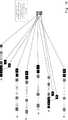
図9,図10には、それぞれアタックシナリオ生成部14によって生成されたアタックシナリオの表示形態を示す。図9,図10は、各要素のイベントを時系列に沿ってチャートとして表示している。プラントのオペレータは、物理的なダメージを避けるために、セキュリティ評価を定期的に確認することができる。 9 and 10 show display forms of attack scenarios generated by the attack
実施の形態2.
実施の形態2にかかるセキュリティアセスメント装置100について、図11を用いて説明する。図11は、セキュリティアセスメント装置100の構成を示す機能ブロック図である。実施の形態2では、ルール記憶部17が設けられていない点で図1の構成と相異している。よって、アセスメント管理部11が各ルールをメモリなどに保存して,処理を行っている。この構成においても、実施の形態1と同様の効果を得ることができる。
A
実施の形態1,2におけるセキュリティアセスメント装置100は、例えば,プロセッサ及びメモリを有するコンピュータによって、実現することができる。例えば、メモリに格納されたプログラムをプロセッサが実行することで、上記のセキュリティアセスメント方法が実施される。各構成要素の処理を、CPU(Central Processing Unit)にコンピュータプログラムを実行させることにより実現することも可能である。 The
その他の実施の形態.
図12は、その他の実施の形態にかかるセキュリティアセスメント装置100の構成を示す機能ブロック図である。セキュリティアセスメント装置100は、コントローラを用いて制御される施設のセキュリティアセスメント装置である。セキュリティアセスメント装置100は、前記施設に設けられた複数の要素に関するデータ及び前記コントローラの制御プログラムコードに基づいて、前記制御対象施設を非安全状態にする感染要素を特定して、感染要素リストを生成する特定部101と、前記感染要素リストから選択された選択要素について、感染振る舞いを生成する感染振る舞い生成部102と、を備えている。これにより、簡便かつ適切にセキュリティリスクを評価することができる。Other embodiments.
FIG. 12 is a functional block diagram showing the configuration of a
上記の実施の形態において、プログラムは、様々なタイプの非一時的なコンピュータ可読媒体(non-transitory computer readable medium)を用いて格納され、コンピュータに供給することができる。非一時的なコンピュータ可読媒体は、様々なタイプの実態のある記録媒体(tangible storage medium)を含む。非一時的なコンピュータ可読媒体の例は、磁気記録媒体(例えばフレキシブルディスク、磁気テープ、ハードディスクドライブ)、光磁気記録媒体(例えば光磁気ディスク)、CD-ROM(Read Only Memory)、CD-R、CD-R/W、半導体メモリ(例えば、マスクROM、PROM(Programmable ROM)、EPROM(Erasable PROM))、フラッシュROM、RAM(Random Access Memory)を含む。また、プログラムは、様々なタイプの一時的なコンピュータ可読媒体(transitory computer readable medium)によってコンピュータに供給されてもよい。一時的なコンピュータ可読媒体の例は、電気信号、光信号、及び電磁波を含む。一時的なコンピュータ可読媒体は、電線及び光ファイバ等の有線通信路、又は無線通信路を介して、プログラムをコンピュータに供給できる。 In the above embodiments, the programs can be stored and delivered to computers using various types of non-transitory computer readable media. Non-transitory computer-readable media include various types of tangible storage media. Examples of non-transitory computer-readable media include magnetic recording media (eg, flexible discs, magnetic tapes, hard disk drives), magneto-optical recording media (eg, magneto-optical discs), CD-ROMs (Read Only Memory), CD-Rs, It includes CD-R/W, semiconductor memory (eg, mask ROM, PROM (Programmable ROM), EPROM (Erasable PROM)), flash ROM, and RAM (Random Access Memory). The program may also be delivered to the computer on various types of transitory computer readable medium. Examples of transitory computer-readable media include electrical signals, optical signals, and electromagnetic waves. Transitory computer-readable media can deliver the program to the computer via wired channels, such as wires and optical fibers, or wireless channels.
以上、実施の形態を参照して本願発明を説明したが、本願発明は上記によって限定されるものではない。本願発明の構成や詳細には、発明のスコープ内で当業者が理解し得る様々な変更をすることができる。 Although the present invention has been described with reference to the embodiments, the present invention is not limited to the above. Various changes that can be understood by those skilled in the art can be made to the configuration and details of the present invention within the scope of the invention.
11 アセスメント管理部
12 制御ルール生成部
13 物理プロセスルール生成部
14 アタックシナリオ生成部
15 感染要素特定部
16 感染振る舞い生成部
17 ルール記憶部
100 セキュリティアセスメント装置
200 プラント
LS001 センサ
WT001 貯水槽
MV001 バルブ
PLC001 コントローラREFERENCE SIGNS LIST 11
Claims (18)
Translated fromJapanese前記施設に設けられた複数の要素に関するデータ、及び前記コントローラの制御プログラムコードに基づいて、前記施設を非安全状態にする感染要素を特定して、感染要素リストを生成する特定部と、
前記感染要素リストの中から選択された選択要素の感染振る舞いを生成する感染振る舞い生成部と、を備えたセキュリティアセスメント装置。A facility security assessment device controlled with a controller, comprising:
an identifying unit that identifies infectious factors that cause the facility to become unsafe based on data on a plurality of elements provided in the facility and the control program code of the controller, and generates an infectious factor list;
an infected behavior generation unit that generates infected behavior of a selected element selected from the infected element list.
前記通常ルールでは、前記要素の入力と出力とを対応付けられており、
前記特定部は、前記非安全状態を指定する変数の値を変化させる前記通常ルールを探索することで、前記感染要素を特定していく請求項1に記載のセキュリティアセスメント装置。The identifying unit receives the normal rule generated based on the control program code and the data,
In the normal rule, the input and output of the element are associated,
2. The security assessment apparatus according to claim 1, wherein the identification unit identifies the infectious element by searching for the normal rule that changes the value of the variable designating the unsafe state.
前記状態リストは、各要素の状態を示しており、
前記感染振る舞い生成部は、前記通常ルールに対応する状態リストにおいて、出力が任意の値を取るようにして、前記感染振る舞いを生成する請求項2に記載のセキュリティアセスメント装置。the infected behavior generator receives a state list generated based on the data and the control program code;
The state list indicates the state of each element,
3. The security assessment apparatus according to claim 2, wherein said infected behavior generation unit generates said infected behavior such that an output takes an arbitrary value in the state list corresponding to said normal rule.
セキュリティアセスメント装置が、前記施設に設けられた複数の要素に関するデータ、及び前記コントローラの制御プログラムコードに基づいて、前記施設を非安全状態にする感染要素を特定するステップと、
前記セキュリティアセスメント装置が、感染要素リストを生成するステップと、
前記セキュリティアセスメント装置が、前記感染要素リストの中から選択された選択要素の感染振る舞いを生成する感染振る舞いステップと、を備えたセキュリティアセスメント方法。A method for security assessment of a facility controlled using a controller, comprising:
a security assessment device identifying infectious factors that cause the facility to become unsecured based on data relating to the plurality of factors provided in the facility and control program code of the controller;
the security assessment device generating an infected element list;
an infected behavior step in which the security assessmentdevice generates an infected behavior of a selected element selected from the infected element list.
前記セキュリティアセスメント装置が、前記非安全状態を指定する変数の値を変化させる前記通常ルールを探索することで、前記感染要素を特定していく請求項7に記載のセキュリティアセスメント方法。Thesecurity assessment device further comprising the step of generating a normal rule that associates the input and output of the element during normal operation based on the control program code and the data;
8. The security assessment method according to claim 7,wherein the security assessment device identifies the infectious element by searching for the normal rule that changes the value of the variable specifying the unsafe state.
前記セキュリティアセスメント装置が、前記通常ルールに対応する状態リストにおいて、出力が任意の値を取るようにして、前記感染振る舞いを生成する請求項8に記載のセキュリティアセスメント方法。furthercomprising the step of the security assessment device generating a status list indicating the status of each element based on the data and the control program code;
9. The security assessment method according to claim 8, whereinsaid security assessment device generates said infected behavior such that an output takes any value in a state list corresponding to said normal rule.
セキュリティアセスメント方法は、
前記施設に設けられた複数の要素に関するデータ、及び前記コントローラの制御プログラムコードに基づいて、前記施設を非安全状態にする感染要素を特定するステップと、
感染要素リストを生成するステップと、
前記感染要素リストの中から選択された選択要素の感染振る舞いを生成する感染振る舞いステップと、を備えた、プログラム。A program for causing a computer to implement a security assessment method for a facility controlled using a controller,
The security assessment method is
identifying an infectious factor that renders the facility unsafe based on data regarding a plurality of factors in the facility and control program code in the controller;
generating an infected element list;
and an infected behavior step of generating an infected behavior for a selected element selected from the infected element list.
前記非安全状態を規定する変数の値を変化させる前記通常ルールを探索することで、前記感染要素を特定していく請求項13に記載のプログラム。The security assessment method further comprises the step of generating a normal rule that associates the input and output of the element during normal operation based on the control program code and the data,
14. The program according to claim 13, wherein the infected element is identified by searching for the normal rule that changes the value of the variable that defines the unsafe state.
前記通常ルールに対応する状態リストにおいて、出力が任意の値を取るようにして、前記感染振る舞いを生成する請求項14に記載のプログラム。The security assessment method further comprises generating a status list indicating the status of each element based on the data and the control program code;
15. The program according to claim 14, wherein in the state list corresponding to the normal rule, the output takes any value to generate the infection behavior.
Applications Claiming Priority (1)
| Application Number | Priority Date | Filing Date | Title |
|---|---|---|---|
| PCT/JP2019/005403WO2020166016A1 (en) | 2019-02-14 | 2019-02-14 | Security assessment apparatus, security assessment method, and non-transitory computer readable medium |
Publications (2)
| Publication Number | Publication Date |
|---|---|
| JP2022519837A JP2022519837A (en) | 2022-03-25 |
| JP7147993B2true JP7147993B2 (en) | 2022-10-05 |
Family
ID=72045214
Family Applications (1)
| Application Number | Title | Priority Date | Filing Date |
|---|---|---|---|
| JP2021545467AActiveJP7147993B2 (en) | 2019-02-14 | 2019-02-14 | SECURITY ASSESSMENT DEVICE, SECURITY ASSESSMENT METHOD, AND PROGRAM |
Country Status (3)
| Country | Link |
|---|---|
| US (1) | US12061730B2 (en) |
| JP (1) | JP7147993B2 (en) |
| WO (1) | WO2020166016A1 (en) |
Citations (3)
| Publication number | Priority date | Publication date | Assignee | Title |
|---|---|---|---|---|
| US20180075243A1 (en) | 2016-09-13 | 2018-03-15 | The Mitre Corporation | System and method for modeling and analyzing the impact of cyber-security events on cyber-physical systems |
| US20180309780A1 (en) | 2017-04-21 | 2018-10-25 | The Mitre Corporation | Methods and systems for evaluating effects of cyber-attacks on cyber-physical systems |
| US20180337939A1 (en) | 2017-05-17 | 2018-11-22 | Anurag Agarwal | Threat Model Chaining and Attack Simulation Systems and Methods |
Family Cites Families (12)
| Publication number | Priority date | Publication date | Assignee | Title |
|---|---|---|---|---|
| US8955105B2 (en)* | 2007-03-14 | 2015-02-10 | Microsoft Corporation | Endpoint enabled for enterprise security assessment sharing |
| US8181247B1 (en)* | 2011-08-29 | 2012-05-15 | Kaspersky Lab Zao | System and method for protecting a computer system from the activity of malicious objects |
| US9930058B2 (en)* | 2014-08-13 | 2018-03-27 | Honeywell International Inc. | Analyzing cyber-security risks in an industrial control environment |
| US10142353B2 (en)* | 2015-06-05 | 2018-11-27 | Cisco Technology, Inc. | System for monitoring and managing datacenters |
| EP3121749B1 (en) | 2015-07-22 | 2019-06-26 | Nxp B.V. | Method and apparatus for ensuring control flow integrity |
| US10193868B2 (en)* | 2015-09-10 | 2019-01-29 | Bae Systems Information And Electronic Systems Integration Inc. | Safe security proxy |
| IL242808A0 (en)* | 2015-11-26 | 2016-04-21 | Rafael Advanced Defense Sys | System and method for detecting a cyber-attack at scada/ics managed plants |
| US10462181B2 (en)* | 2016-05-10 | 2019-10-29 | Quadrant Information Security | Method, system, and apparatus to identify and study advanced threat tactics, techniques and procedures |
| JP6786959B2 (en)* | 2016-08-26 | 2020-11-18 | 富士通株式会社 | Cyber attack analysis support program, cyber attack analysis support method and cyber attack analysis support device |
| WO2018122050A1 (en)* | 2016-12-30 | 2018-07-05 | British Telecommunications Public Limited Company | Historic data breach detection |
| WO2018138608A2 (en)* | 2017-01-30 | 2018-08-02 | XM Ltd. | Penetration testing of a networked system |
| US11258817B2 (en)* | 2018-10-26 | 2022-02-22 | Tenable, Inc. | Rule-based assignment of criticality scores to assets and generation of a criticality rules table |
- 2019
- 2019-02-14JPJP2021545467Apatent/JP7147993B2/enactiveActive
- 2019-02-14WOPCT/JP2019/005403patent/WO2020166016A1/ennot_activeCeased
- 2019-02-14USUS17/430,069patent/US12061730B2/enactiveActive
Patent Citations (3)
| Publication number | Priority date | Publication date | Assignee | Title |
|---|---|---|---|---|
| US20180075243A1 (en) | 2016-09-13 | 2018-03-15 | The Mitre Corporation | System and method for modeling and analyzing the impact of cyber-security events on cyber-physical systems |
| US20180309780A1 (en) | 2017-04-21 | 2018-10-25 | The Mitre Corporation | Methods and systems for evaluating effects of cyber-attacks on cyber-physical systems |
| US20180337939A1 (en) | 2017-05-17 | 2018-11-22 | Anurag Agarwal | Threat Model Chaining and Attack Simulation Systems and Methods |
Also Published As
| Publication number | Publication date |
|---|---|
| JP2022519837A (en) | 2022-03-25 |
| US20220147659A1 (en) | 2022-05-12 |
| WO2020166016A1 (en) | 2020-08-20 |
| US12061730B2 (en) | 2024-08-13 |
Similar Documents
| Publication | Publication Date | Title |
|---|---|---|
| US10809704B2 (en) | Process performance issues and alarm notification using data analytics | |
| JP6941965B2 (en) | Domain-level threat detection for industrial asset control systems | |
| US10521550B2 (en) | Planning and engineering method, software tool and simulation tool for an automation solution | |
| US10901406B2 (en) | Method of monitoring and controlling an industrial process, and a process control system | |
| EP3771951B1 (en) | Using data from plc systems and data from sensors external to the plc systems for ensuring data integrity of industrial controllers | |
| Bao et al. | Risk‐based fault diagnosis and safety management for process systems | |
| TWI710873B (en) | Support device, learning device, and plant operating condition setting support system | |
| US20160364456A1 (en) | Computerized process safety management system | |
| JP2020513130A (en) | Apparatus and method for streamlining and analyzing alarms in industrial process control and automation systems | |
| EP4377822B1 (en) | Computer-implemented method and surveillance arrangement for identifying manipulations of cyber-physical-systems as well as computer-implemented-tool and cyber-physical-system | |
| US20240241494A1 (en) | Computer-implemented method and surveillance arrangement for identifying manipulations of cyber-physical-systems as well as computer-implemented-tool and cyber-physical-system | |
| JP2022182620A (en) | Information processing device, prediction method and prediction program | |
| Azzam et al. | Grounds for suspicion: Physics-based early warnings for stealthy attacks on industrial control systems | |
| EP4038557A1 (en) | Method and system for continuous estimation and representation of risk | |
| JP2014032633A (en) | Plant monitoring apparatus and plant operation method | |
| JP7147993B2 (en) | SECURITY ASSESSMENT DEVICE, SECURITY ASSESSMENT METHOD, AND PROGRAM | |
| KR20140068519A (en) | Risk evaluation system and method for selection of functional equipment group | |
| JP2022182621A (en) | Information processing device, display control method and display control program | |
| US20210333787A1 (en) | Device management system, model learning method, and model learning program | |
| WO2015037066A1 (en) | System for supporting operation during plant accidents and method for supporting operation during plant accidents | |
| JP7416015B2 (en) | Information processing device, alarm prediction method, and alarm prediction program | |
| JP7517286B2 (en) | Information processing device, evaluation method, and evaluation program | |
| JP7248101B2 (en) | MONITORING METHOD, MONITORING DEVICE, AND PROGRAM | |
| WO2020021685A1 (en) | Plant monitoring device, plant monitoring method, and computer-readable recording medium | |
| JP7318798B2 (en) | SECURITY ASSESSMENT DEVICE, SECURITY ASSESSMENT METHOD, AND PROGRAM |
Legal Events
| Date | Code | Title | Description |
|---|---|---|---|
| A521 | Request for written amendment filed | Free format text:JAPANESE INTERMEDIATE CODE: A523 Effective date:20210803 | |
| A621 | Written request for application examination | Free format text:JAPANESE INTERMEDIATE CODE: A621 Effective date:20210803 | |
| A131 | Notification of reasons for refusal | Free format text:JAPANESE INTERMEDIATE CODE: A131 Effective date:20220726 | |
| A521 | Request for written amendment filed | Free format text:JAPANESE INTERMEDIATE CODE: A523 Effective date:20220810 | |
| TRDD | Decision of grant or rejection written | ||
| A01 | Written decision to grant a patent or to grant a registration (utility model) | Free format text:JAPANESE INTERMEDIATE CODE: A01 Effective date:20220823 | |
| A61 | First payment of annual fees (during grant procedure) | Free format text:JAPANESE INTERMEDIATE CODE: A61 Effective date:20220905 | |
| R151 | Written notification of patent or utility model registration | Ref document number:7147993 Country of ref document:JP Free format text:JAPANESE INTERMEDIATE CODE: R151 |