JP7147925B2 - Drug sorting device and drug sorting method - Google Patents
Drug sorting device and drug sorting methodDownload PDFInfo
- Publication number
- JP7147925B2 JP7147925B2JP2021095792AJP2021095792AJP7147925B2JP 7147925 B2JP7147925 B2JP 7147925B2JP 2021095792 AJP2021095792 AJP 2021095792AJP 2021095792 AJP2021095792 AJP 2021095792AJP 7147925 B2JP7147925 B2JP 7147925B2
- Authority
- JP
- Japan
- Prior art keywords
- medicine
- returned
- tray
- drug
- storage tray
- Prior art date
- Legal status (The legal status is an assumption and is not a legal conclusion. Google has not performed a legal analysis and makes no representation as to the accuracy of the status listed.)
- Active
Links
Images


Classifications
- A—HUMAN NECESSITIES
- A61—MEDICAL OR VETERINARY SCIENCE; HYGIENE
- A61J—CONTAINERS SPECIALLY ADAPTED FOR MEDICAL OR PHARMACEUTICAL PURPOSES; DEVICES OR METHODS SPECIALLY ADAPTED FOR BRINGING PHARMACEUTICAL PRODUCTS INTO PARTICULAR PHYSICAL OR ADMINISTERING FORMS; DEVICES FOR ADMINISTERING FOOD OR MEDICINES ORALLY; BABY COMFORTERS; DEVICES FOR RECEIVING SPITTLE
- A61J3/00—Devices or methods specially adapted for bringing pharmaceutical products into particular physical or administering forms
- G—PHYSICS
- G07—CHECKING-DEVICES
- G07F—COIN-FREED OR LIKE APPARATUS
- G07F11/00—Coin-freed apparatus for dispensing, or the like, discrete articles
- G07F11/46—Coin-freed apparatus for dispensing, or the like, discrete articles from movable storage containers or supports
- G07F11/60—Coin-freed apparatus for dispensing, or the like, discrete articles from movable storage containers or supports the storage containers or supports being rectilinearly movable
- G—PHYSICS
- G06—COMPUTING OR CALCULATING; COUNTING
- G06K—GRAPHICAL DATA READING; PRESENTATION OF DATA; RECORD CARRIERS; HANDLING RECORD CARRIERS
- G06K19/00—Record carriers for use with machines and with at least a part designed to carry digital markings
- G06K19/06—Record carriers for use with machines and with at least a part designed to carry digital markings characterised by the kind of the digital marking, e.g. shape, nature, code
- G06K19/06009—Record carriers for use with machines and with at least a part designed to carry digital markings characterised by the kind of the digital marking, e.g. shape, nature, code with optically detectable marking
- G06K19/06018—Record carriers for use with machines and with at least a part designed to carry digital markings characterised by the kind of the digital marking, e.g. shape, nature, code with optically detectable marking one-dimensional coding
- G06K19/06028—Record carriers for use with machines and with at least a part designed to carry digital markings characterised by the kind of the digital marking, e.g. shape, nature, code with optically detectable marking one-dimensional coding using bar codes
- G—PHYSICS
- G06—COMPUTING OR CALCULATING; COUNTING
- G06K—GRAPHICAL DATA READING; PRESENTATION OF DATA; RECORD CARRIERS; HANDLING RECORD CARRIERS
- G06K7/00—Methods or arrangements for sensing record carriers, e.g. for reading patterns
- G06K7/10—Methods or arrangements for sensing record carriers, e.g. for reading patterns by electromagnetic radiation, e.g. optical sensing; by corpuscular radiation
- G06K7/14—Methods or arrangements for sensing record carriers, e.g. for reading patterns by electromagnetic radiation, e.g. optical sensing; by corpuscular radiation using light without selection of wavelength, e.g. sensing reflected white light
- G06K7/1404—Methods for optical code recognition
- G06K7/1408—Methods for optical code recognition the method being specifically adapted for the type of code
- G06K7/1413—1D bar codes
- G—PHYSICS
- G06—COMPUTING OR CALCULATING; COUNTING
- G06Q—INFORMATION AND COMMUNICATION TECHNOLOGY [ICT] SPECIALLY ADAPTED FOR ADMINISTRATIVE, COMMERCIAL, FINANCIAL, MANAGERIAL OR SUPERVISORY PURPOSES; SYSTEMS OR METHODS SPECIALLY ADAPTED FOR ADMINISTRATIVE, COMMERCIAL, FINANCIAL, MANAGERIAL OR SUPERVISORY PURPOSES, NOT OTHERWISE PROVIDED FOR
- G06Q10/00—Administration; Management
- G06Q10/08—Logistics, e.g. warehousing, loading or distribution; Inventory or stock management
- G06Q10/087—Inventory or stock management, e.g. order filling, procurement or balancing against orders
- G—PHYSICS
- G06—COMPUTING OR CALCULATING; COUNTING
- G06T—IMAGE DATA PROCESSING OR GENERATION, IN GENERAL
- G06T7/00—Image analysis
- G06T7/70—Determining position or orientation of objects or cameras
- G—PHYSICS
- G06—COMPUTING OR CALCULATING; COUNTING
- G06V—IMAGE OR VIDEO RECOGNITION OR UNDERSTANDING
- G06V10/00—Arrangements for image or video recognition or understanding
- G06V10/10—Image acquisition
- G—PHYSICS
- G07—CHECKING-DEVICES
- G07F—COIN-FREED OR LIKE APPARATUS
- G07F17/00—Coin-freed apparatus for hiring articles; Coin-freed facilities or services
- G07F17/0092—Coin-freed apparatus for hiring articles; Coin-freed facilities or services for assembling and dispensing of pharmaceutical articles
- H—ELECTRICITY
- H04—ELECTRIC COMMUNICATION TECHNIQUE
- H04N—PICTORIAL COMMUNICATION, e.g. TELEVISION
- H04N23/00—Cameras or camera modules comprising electronic image sensors; Control thereof
- A—HUMAN NECESSITIES
- A61—MEDICAL OR VETERINARY SCIENCE; HYGIENE
- A61J—CONTAINERS SPECIALLY ADAPTED FOR MEDICAL OR PHARMACEUTICAL PURPOSES; DEVICES OR METHODS SPECIALLY ADAPTED FOR BRINGING PHARMACEUTICAL PRODUCTS INTO PARTICULAR PHYSICAL OR ADMINISTERING FORMS; DEVICES FOR ADMINISTERING FOOD OR MEDICINES ORALLY; BABY COMFORTERS; DEVICES FOR RECEIVING SPITTLE
- A61J2205/00—General identification or selection means
- A61J2205/10—Bar codes
- A—HUMAN NECESSITIES
- A61—MEDICAL OR VETERINARY SCIENCE; HYGIENE
- A61J—CONTAINERS SPECIALLY ADAPTED FOR MEDICAL OR PHARMACEUTICAL PURPOSES; DEVICES OR METHODS SPECIALLY ADAPTED FOR BRINGING PHARMACEUTICAL PRODUCTS INTO PARTICULAR PHYSICAL OR ADMINISTERING FORMS; DEVICES FOR ADMINISTERING FOOD OR MEDICINES ORALLY; BABY COMFORTERS; DEVICES FOR RECEIVING SPITTLE
- A61J2205/00—General identification or selection means
- A61J2205/40—General identification or selection means by shape or form, e.g. by using shape recognition
- H—ELECTRICITY
- H04—ELECTRIC COMMUNICATION TECHNIQUE
- H04N—PICTORIAL COMMUNICATION, e.g. TELEVISION
- H04N23/00—Cameras or camera modules comprising electronic image sensors; Control thereof
- H04N23/90—Arrangement of cameras or camera modules, e.g. multiple cameras in TV studios or sports stadiums
Landscapes
- Engineering & Computer Science (AREA)
- Physics & Mathematics (AREA)
- General Physics & Mathematics (AREA)
- Theoretical Computer Science (AREA)
- Business, Economics & Management (AREA)
- Health & Medical Sciences (AREA)
- Economics (AREA)
- General Health & Medical Sciences (AREA)
- Computer Vision & Pattern Recognition (AREA)
- Electromagnetism (AREA)
- Toxicology (AREA)
- Artificial Intelligence (AREA)
- Human Resources & Organizations (AREA)
- Development Economics (AREA)
- Finance (AREA)
- Entrepreneurship & Innovation (AREA)
- Accounting & Taxation (AREA)
- Marketing (AREA)
- Operations Research (AREA)
- Quality & Reliability (AREA)
- Strategic Management (AREA)
- Tourism & Hospitality (AREA)
- General Business, Economics & Management (AREA)
- Multimedia (AREA)
- Chemical & Material Sciences (AREA)
- Medicinal Chemistry (AREA)
- Pharmacology & Pharmacy (AREA)
- Life Sciences & Earth Sciences (AREA)
- Animal Behavior & Ethology (AREA)
- Public Health (AREA)
- Veterinary Medicine (AREA)
- Signal Processing (AREA)
- Medical Preparation Storing Or Oral Administration Devices (AREA)
Description
Translated fromJapanese本発明は、薬剤仕分装置及び薬剤仕分方法に関する。 The present invention relates to a medicine sorting device and a medicine sorting method.
患者に処方された薬剤が、処方変更等の理由により医療機関内の薬剤処方を管理する部署に返却される場合がある(返品薬剤)。特許文献1には、返品薬剤の処理作業の効率化と、この作業におけるヒューマンエラー防止のための、返品薬剤を自動的に認識して格納する返品薬剤仕分装置を開示している。 A drug prescribed to a patient may be returned to a department that manages drug prescription within a medical institution due to a prescription change or the like (returned drug).
一般に、返品薬剤は、種類、形状、大きさ、使用期限等の性状が種々異なる。しかし、特許文献1に開示されたものを含め、従来の返品薬剤仕分装置では、性状が種々異なる返品薬剤をその後の払出作業の効率等の要因を考慮した高い自由度を確保して格納することについて、特段の考慮が払われていない。より具体的には、性状が種々異なる返品薬剤を、例えば処方情報に応じた自由な払い出しが可能となるように、高い自由度を確保して格納することについて、特段の考慮が払われていない。 In general, returned medicines have various properties such as type, shape, size, expiration date, and the like. However, in the conventional returned medicine sorting apparatuses, including the one disclosed in
本発明は、種類、形状、大きさ、使用期限等の性状が種々異なり、かつ非整列状態で供給された薬剤を、自動的に認識して高い自由度を確保して格納することを課題とする。 An object of the present invention is to automatically recognize and store medicines with various properties such as types, shapes, sizes, expiration dates, etc., which are supplied in a non-aligned state, while securing a high degree of freedom. do.
本発明の第1の態様は、薬剤仕分装置であって、薬剤を格納する格納トレーと、処方データに基づいて前記薬剤を前記格納トレーから払い出す、払出機構とを備え、前記格納トレーには、前記薬剤が取出可能に保持され、前記格納トレーに格納された個々の前記薬剤についての種類と前記格納トレー内の位置とを関連付けた情報が記憶されており、前記払出機構は、前記記憶された情報に基づいて、前記処方データに含まれる前記薬剤が前記格納トレーにあれば、当該薬剤を前記格納トレーから払い出し、前記薬剤仕分け装置は、前記薬剤が格納された返品トレーと、前記返品トレーを受け入れる受入部とをさらに備え、前記薬剤仕分装置は、前記返品トレーから前記薬剤を取り出して前記格納トレーに格納し、前記薬剤仕分装置は、前記薬剤の軸線が延びる方向を認識する認識部をさらに備え、前記薬剤仕分装置は、前記認識部で認識された前記薬剤の前記軸線が延びる方向が予め定められた方向となるように前記薬剤を前記格納トレーに格納するように構成されている、薬剤仕分装置を提供する。
A first aspect of the present invention is amedicine sorting apparatus, comprising a storage tray forstoring medicines, and a dispensing mechanism for dispensing the medicines from the storage tray based on prescription data, wherein the storage tray stores information that associates the type of each drug stored in the storage tray with the position in the storage tray, and the dispensing mechanism stores the Based on the stored information, if the medicine included in the prescription data is in the storage tray, the medicine is dispensed from the storage tray, and the medicine sorting device stores the medicine as a return tray in which the medicine is stored. and a receiving unit for receiving the returned goods tray, wherein the medicine sorting device takes out the medicines from the returned goods tray and stores them in the storage tray, and the medicine sorting device recognizes the direction in which the axis of the medicines extends. The medicine sorting apparatus is configured to store the medicines in the storage tray such that the extending direction of the axis of the medicine recognized by the recognition part is a predetermined direction. to provide a drug sorting device.
認識部は、薬剤の向き、姿勢、及び性状(種類、形状、大きさ、使用期限等を含む)を認識する。格納部には、少なくとも認識部で認識された大きさに応じて格納時に設定される格納範囲と、個々の薬剤の識別情報とを関連付けて、薬剤が個別に配置される。格納部に格納された薬剤は個別に取出可能である。従って、薬剤の向き、姿勢、及び性状を自動的に認識し、例えば処方情報に応じた自由な払い出しが可能であるような、高い自由度を確保して格納することができる。 The recognition unit recognizes the orientation, posture, and properties (including type, shape, size, expiry date, etc.) of the medicine. In the storage unit, the medicines are individually arranged by associating the storage range set at the time of storage according to at least the size recognized by the recognition unit and the identification information of each medicine. Medicines stored in the storage can be taken out individually. Therefore, it is possible to automatically recognize the orientation, posture, and properties of the drug, and to store the drug with a high degree of freedom, such as enabling free dispensing according to the prescription information.
本発明の第2の態様は、薬剤が格納された返品トレーを受入部に受け入れ、前記薬剤の軸線が延びる方向を認識部で認識し、前記薬剤を、前記薬剤が取出可能に保持される格納トレーに、前記認識部で認識された前記薬剤の前記軸線が延びる方向が予め定められた方向となるように格納し、前記格納トレーに格納された個々の前記薬剤についての種類と前記格納トレー内の位置とを関連付けた情報を記憶し、前記記憶された情報に基づいて、前記処方データに含まれる前記薬剤が前記格納トレーにあれば、当該薬剤を前記格納トレーから払い出す、薬剤仕分方法を提供する。
A second aspect of the present invention is astorage device in which a return tray storing medicine is received in a receiving part, thedirection in which the axis of the medicine extends is recognized by the recognition part, and the medicine is held removably.The medicines recognized by the recognition unit are stored in the tray so that the direction in which the axis extends is a predetermined direction, and the types and the contents of the medicines stored in the storage tray are stored in the storage tray.and storing information associated with the position of the drug, and based on the stored information, if the drug included in the prescription data is in the storage tray, the drug is dispensed from the storage tray. offer.
本発明の薬剤仕分装置及び薬剤仕分方法によれば、薬剤の向き及び姿勢と、形状、大きさ、種類、使用期限のような性状とを自動的に認識し、例えば処方情報に応じた自由な払い出しが可能であるような、高い自由度を確保して薬剤を格納できる。 According to the medicine sorting apparatus and the medicine sorting method of the present invention, the orientation and posture of medicines and properties such as shape, size, type and expiration date can be automatically recognized, and the medicines can be freely sorted according to prescription information, for example. Medicines can be stored with a high degree of freedom such that they can be dispensed.
(装置の概要)
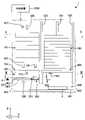
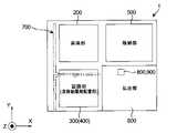
図1から図6は、本発明の実施形態に係る返品薬剤供給装置(薬剤仕分装置)1を示す。返品薬剤供給装置1は、受入部100、昇降部200、認識部300、非格納薬剤配置部400、格納部500、及び払出部600を備える。また、返品薬剤供給装置1は、直交型ロボット700、スカラー型ロボット800、及びサポートトレー900を備える。さらに、返品薬剤供給装置1は、図1に模式的に示す制御装置1000を備える。制御装置1000は、図4に図示する制御盤1001(ディスプレイ1002を備える)からの入力、センサやカメラからの入力等に基づいて、返品薬剤供給装置1の動作を統括的に制御する。(Apparatus overview)
1 to 6 show a returned medicine supply device (medicine sorting device) 1 according to an embodiment of the present invention. The returned-goods
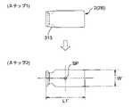
返品薬剤供給装置1の主な機能の概要は、以下の通りである。返品薬剤供給装置1は、例えばアンプル2A、バイアル2B、樹脂アンプル2Cである返品薬剤2(図8参照)の形状、大きさ(長さL1と直径ないし幅W)、種類、使用期限のような性状を認識する。本実施形態では、返品薬剤2には、種類、使用期限等に関する情報を含む文字情報やバーコードが印刷されたラベル3が貼り付けられている。返品薬剤供給装置1は、ラベル3に表示されたこれらの情報を読み取る。また、返品薬剤供給装置1は、認識後の返品薬剤2をその返品薬剤2の識別情報(1個1個の返品薬剤2に付与されたユニークな情報)と関連付けて一時的に格納し、処方データ(例えば電子カルテシステムである上位のシステム(HIS: Hospital Information System)から受信する。)に基づいて、払い出しを行う。格納時には、格納される返品薬剤2の大きさに応じて格納領域が設定される。返品薬剤2の格納は、設定された格納領域に配置された、かつ払出時に個別の返品薬剤2を取出可能となる態様で行われる。さらに、返品薬剤供給装置1は、使用期限が過ぎている返品薬剤2を排出する。「使用期限」の用語に代わって、「有効期限」の用語が使用される場合がある。ただ、これらの用語は実質的には同義である。そこで、本明細書では、混乱を回避するために、「有効期限」を用いずに、「使用期限」のみを使用する。 An overview of the main functions of the returned-goods
(受入部)
図1から図3に示すように、受入部100は、返品薬剤供給装置1を正面から見て左上手前側に配置されている。(receiving department)
As shown in FIGS. 1 to 3, the receiving
図7を併せて参照すると、受入部100は、水平方向(図においてX方向)に互いに対向して配置された固定のラック部材101を備える。ラック部材101には、複数の返品トレー(受入容器)4を多段配置された状態で保持するための、複数対のレール溝101a,101aが設けられている。 Also referring to FIG. 7, the receiving
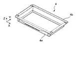
図8及び図9を参照すると、返品トレー4は、図において上方が開口したトレー本体4aと、トレー本体4aの上端縁に設けられたフランジ状部4bとを備える。図8に示すように、返品トレー4に収容されている返品薬剤2(例えばアンプル2A、バイアル2B、樹脂アンプル2C)は、形状、大きさ(長さL1と幅W)、種類、使用期限のような性状が異なっている。また、返品トレー4に収容されている返品薬剤2の向きと姿勢は揃えられておらず、互いに異なる。つまり、返品トレー4に収容されている返品薬剤2は、非整列状態である。ここで返品薬剤2の向きは、図においてXY平面において返品薬剤2の長手方向(返品薬剤2の軸線A)が延びる方向をいう。返品薬剤2についての向きという用語は、返品薬剤2の軸線Aが延びる向きに加え、返品薬剤2の先端2aと基端2bの向いている方向を含む場合がある。ただし、返品トレー4に収容されている返品薬剤2の形状、大きさ、種類、使用期限のような性状が統一されていてもよい。また、返品トレー4に収容されている返品薬剤2の向き及び姿勢が揃えられていてもよい。返品トレー4中の返品薬剤2は、互いに重なり合わせないように収容されている。 Referring to FIGS. 8 and 9, the
図7に示すように、ラック部材101に設けられたレール溝101a,101aにより、返品トレー4のフランジ状4bが支持されている。レール溝101a,101aは、ラック部材101の図においてX方向手前側の端面から奥側の端面まで貫通するように設けられている。そのため、医療従業者のような作業者は、返品薬剤供給装置1の正面側から、返品トレー4をレール溝101a,101aに対して出し入れできる。また、後述する昇降部200は、返品薬剤供給装置1の背面側から返品トレー4をレール溝101a,101aに対して出し入れできる。
(昇降部)As shown in FIG. 7,
(lifting part)
図1から図3に示すように、昇降部200は、返品薬剤供給装置1を正面から見て左奥に配置されている。 As shown in FIGS. 1 to 3, the
図10を併せて参照すると、昇降部200は、Z方向に延びる固定の直動ガイド201と、直動ガイド201に沿って昇降するキャリッジ202と、キャリッジ202に搭載されたテーブル203を備える。テーブル203は底部203aと、底部203aに左右に設けられた側部203b,203bと、底部203aの奥側(Y方向の奥側)に設けられた端部203cとを備える。テーブル203は手前側(Y方向の手前側)が開放している。側部203b,203bには、レール溝204,204が設けられている。レール溝204,204により、返品トレー4のフランジ状4bが支持され、それによってテーブル203に返品トレー4が保持される。 Also referring to FIG. 10 , the
引き続き図10を参照すると、底部203aには返品薬剤供給装置1の奥行方向(Y方向)に延びる固定の直動ガイド205が設けられている。また、この直動ガイド205に沿って水平移動するキャリッジ206に、フック207の基端側が固定されている。 Continuing to refer to FIG. 10, a fixed direct-acting guide 205 extending in the depth direction (Y direction) of the returned-
昇降部200は、受入部100から1個の返品トレー4を取り出して、後述する認識部300と同様の高さ位置(図1において符号Hで概念的に示す)まで降下させることができる(返却トレー取出動作)。また、昇降部200は、認識部300と同様の高さ位置Hから返品トレー4を受入部100に戻すことができる(返却トレー戻し動作)。 The
返却トレー取出動作について説明すると、まず、テーブル203(キャリッジ202)が、取り出し対象の返品トレー4が保持されている受入部100のレール溝101a,101aよりも少し低い位置まで上昇する。次に、フック207(キャリッジ206)が、テーブル203の端部203c側から前進移動(Y方向手前側へ移動)する。続いて、テーブル203が少し上昇し、その結果、返品トレー4のフランジ状部4b(図において奥側の部分)とトレー本体4aとの間の隙間に、フック207が進入する。その後、フック207が、テーブル203の端部203cへ後退移動(Y方向奥側へ移動)する。このフック207の後退移動により、フランジ状部4bがレール溝204に引き込まれ、返品トレー4が受入部100からテーブル203に移載される。最後に、テーブル203(キャリッジ202)が符号Hで示す位置まで降下する。 First, the table 203 (carriage 202) rises to a position slightly lower than the
返却トレー戻し動作について説明すると、まず、テーブル203(キャリッジ202)が符号Hで示す高さ位置から、返品トレー4を戻すレール溝101a,101a(返品トレー4を保持していない)に対応する高さまで上昇する。次に、その後、フック207(キャリッジ206)が、テーブル203の端部203c側から前進移動(Y方向手前側へ移動)する。その結果、フック207によって押された返品トレー4のフランジ状部4bは、レール溝204,204から抜け出て、受入部100のレール溝101a,101aに進入する。その後、テーブル203が少し降下し、それによってフック207は返品トレー4のフランジ状部4b(図において奥側の部分)とトレー本体4aとの間の隙間から下方に抜け出る。最後に、フック207が、テーブル203の端部203c側に後退移動する。 First, the table 203 (carriage 202) moves from a height H to a height corresponding to the
(直交型ロボット)
図11を参照すると、直交型ロボット700(第1ピッキング部)は、図示しない真空源から供給される真空により返品薬剤2を解放可能に吸着する吸着ノズル701を備える。吸着ノズル701の先端には、ゴム製の吸着パッド702が取り付けられている。図1から図3を参照すると、吸着ノズル701が返品薬剤2を吸着保持し、又は吸着保持した返品薬剤2を吸着解除により離すことができる範囲が、昇降部200(前述の高さ位置Hにあるときの返品トレー4)の全範囲と、認識部300及び非格納薬剤位置部400を含むように、直交型ロボット700は構成されている。(orthogonal robot)
Referring to FIG. 11, an orthogonal robot 700 (first picking unit) includes a
直交型ロボット700(吸着ノズル701)は、昇降部200のテーブル203(高さ位置H)に保持された返品トレー4から返品薬剤2を吸着保持して取り出し、認識部300が備える後述の仮置き部(第1認識部)301に移送できる。また、直交型ロボット700は仮置き部301から返品薬剤2を吸着保持して取り出し、認識部300が備える後述のラベル読取部(第2認識部)302に移送できる。さらに、直交型ロボット700は、ラベル読取部302から返品薬剤2を吸着保持して取り出し、非格納薬剤配置部400に移送できる。 The orthogonal robot 700 (suction nozzle 701) sucks and holds the returned
図1から図3及び図11を参照すると、直交型ロボット700は受入部100よりも下方側で返品薬剤供給装置1の奥行き方向(Y方向)に延びる固定のY軸ビーム703と、このY軸ビーム703に沿って移動するキャリッジ704とを備える。キャリッジ704には、返品薬剤供給装置1の幅方向(X方向)に延びるX軸ビーム705が固定されている。また、X軸ビーム705上を移動するキャリッジ706が設けられ、このキャリッジ706にヘッド707が搭載されている。ヘッド707にはボール螺子機構により昇降する昇降ロッド708が設けられている。昇降ロッド708の下端に固定されたブラケット709に、吸着ノズル701が保持されている。吸着ノズル701は、ブラケット709に対してZ軸回りに回転する。ブラケット709と吸着ノズル701の間には、図11のみ図示するばね710が介装されており、吸着ノズル701はブラケット709に対して弾性的に上昇可能である。また、キャリッジ706には、ブラケット709に対する吸着ノズル701の相対的な高さ位置(Z方向の位置)を検出するための位置センサ(図示せず)が搭載されている。 Referring to FIGS. 1 to 3 and 11, the
吸着ノズル701に吸着保持された返品薬剤2は、キャリッジ706の直動によりX方向に移動し、キャリッジ704の直動によりY方向に移動し、昇降ロッド708の昇降によりZ方向に移動する。また、吸着ノズル701に吸着保持された返品薬剤2は、吸着ノズル701のブラケット709に対する回転により、吸着ノズル701の軸線(Z軸)回りに回転する。 The returned
(認識部と非格納薬剤配置部)
図1から図3を参照すると、認識部300は、照明303とカメラ(第1撮影部)304を備える。照明303とカメラ304は、昇降部200の上方に位置している。また、認識部300は、カメラ304と共に本発明における第1認識部の一例を構成する仮置き部301とラベル読取部(本発明における第2認識部の一例)302を備える。仮置き部301とラベル読取部302は、返品薬剤供給装置1を正面から見て左下手前側に配置され、受入部100の下方に位置している。(Recognition unit and non-stored drug placement unit)
Referring to FIGS. 1 to 3,
図12を併せて参照すると、仮置き部301は、返品薬剤2が載置される半透明板305と、この半透明板305の下側に配置された照明306と、半透明板305の上方に位置するカメラ307(第2撮影部)を備える。 Referring also to FIG. 12 , the
図13を併せて参照すると、ラベル読取部302は、回転駆動される無端ベルト308と、この無端ベルト308上に配置されたローラ309とを備える。返品薬剤2は、無端ベルト308とローラ309が回転することで、それ自体の長手方向の軸線A回りに回転する。また、ラベル読取部302は照明310と図1にのみ図示するカメラ311(本発明における第3撮影部の一例)を備える。さらに、ラベル読取部302はバーコードリーダ(第1バーコードリーダ)312を備える。 Also referring to FIG. 13 , the
図12を参照すると、非格納薬剤配置部400は、仮置き部301に隣接し配置された2個の非格納薬剤配置箱401,402を備える。これらの非格納薬剤配置箱401,402は、後述する格納トレー(格納容器)5と同様の、返品薬剤2を保持するための配置溝を備える。 Referring to FIG. 12 , the non-stored
(返品薬剤の認識完了までの動作)
ここで、受入部100の返品トレー4に収容された返品薬剤2に対する、向き及び姿勢と、種類、形状、大きさ、使用期限等の性状との認識が完了するまでの、返品薬剤供給装置1の動作を説明する。(Operation until completion of recognition of returned medicine)
Here, the returned-goods
まず、受入部100から昇降部200のテーブル203に返品トレー4が移載される。返品トレー4の移載後、テーブル203は、高さ位置H(図1参照)まで降下する。テーブル203が高さ位置Hまで降下した後に、認識部300による認識が開始される。まず、照明303からテーブル203上の返品トレー4に対して上方から照明光(指向性の高い光であることが好ましい)を照射しつつ、カメラ304による撮影を行う。カメラ304により撮影された画像に含まれる返品薬剤2が照明光を強く反射している細長い領域から、返品トレー4中の返品薬剤2の位置、向き(XY平面において軸Aが延びる方向であって先端2aと基端2bが向いている方向は含まない)、返品薬剤2の略中間位置(返品薬剤2の吸着保持に適した位置)が認識される。この認識結果に基づいて、直交型ロボット700の吸着ノズル701が返品トレー4中の返品薬剤2を1個ずつ吸着保持し、仮置き部301の半透明板305上に移載する(図12参照)。この際、吸着ノズル701は、それ自体の軸線(Z軸)回りの回転により、吸着保持した返品薬剤2の向きを調節する。 First, the
仮置き部301では、照明306により半透明板305の下方から照明光(高輝度の光であることが好ましい)を照射しつつ、カメラ307による撮影を行う。カメラ307で撮影された画像により、返品薬剤2の形状、大きさ、及び向き(XY平面において軸線Aが延びる方向であって先端2aと基端2bが向いている方向も含む)が認識される。また、カメラ307で撮影された画像により、返品薬剤2の吸着位置(直交型ロボット700の吸着ノズル701とスカラー型ロボット800の吸着ノズル801で吸着される位置)が算出される。返品薬剤2の吸着位置の算出は後に詳述する。カメラ307で撮影された画像による認識結果に基づいて、直交型ロボット700の吸着ノズル701が半透明板305上の返品薬剤2を吸着保持し、ラベル読取部302に移載する。この際、吸着ノズル701は、それ自体の軸線(Z軸)回りに回転により、吸着保持した返品薬剤2の向きを調節する。 In the
ラベル読取部302では、詳細は後述するが、無端ベルト308とローラ309の回転により、返品薬剤2がそれ自体の軸線A(図13参照)回りに回転する。この回転する返品薬剤2に対し、照明310から照明光を照射しつつ、カメラ311による撮影を行う。カメラ311が撮影した画像により、返品薬剤2のラベル3に表示された使用期限等に関する文字情報が認識されると共に、軸線A回りの返品薬剤2の姿勢が認識される。また、カメラ311による撮影に加え、バーコードリーダ312によって、ラベル3に含まれるバーコードが読み取られる。カメラ311が撮影した画像とバーコードリーダ312により読み取られたバーコードにより、返品薬剤2の種類と使用期限が認識される。薬剤の種類及び使用期限の認識は、カメラ311が撮像した画像とバーコードリーダ312によるバーコードの読み取りのいずれか一方のみで行っても良い。例えば、返品薬剤2のラベル3に含まれるバーコードに返品薬剤2の種類と使用期限が含まれている場合、カメラ311を設けずにバーコードリーダ312のみを設け、バーコードリーダ312によるバーコードの読み取りによって、返品薬剤2の種類と使用期限を認識できる。認識終了後、ラベル3のバーコードが表示された領域が上向き(Z方向向き)となる姿勢で返品薬剤2の軸線A回りの回転が停止するように、無端ベルト308とローラ309の回転が停止する。ラベルが上向きであるか否かは、カメラ311の撮影画像に基づいて確認することができる。なお、後述のスカラー型ロボット800の吸着ノズル801が吸着不可能な領域が返品薬剤2に存在する場合(例えば、樹脂アンプル2Cの側面のようにバリが存在する領域や吸着するとラベルがはがれうる領域が返品薬剤2に存在する場合)、その領域が上向きにならないように返品薬剤2の回転が停止されるのが好ましい。そのために、その吸着不可能領域が、薬剤に関連付けされて、後述する薬剤マスターに予め登録されている(予め記憶されている)。 In the
ラベル読取部302では、一対のローラではなく、無端ベルト308とローラ309の回転により、返品薬剤2を軸線A回りに回転させる。無端ベルト308とローラ309の組み合わせは、一対のローラと比較して、回転させることができる返品薬剤2の形状、大きさ、及び種類の範囲が広い。 In the
仮に、ラベル読取部302が一対のローラによって返品薬剤2を回転させる構成である場合、一対のローラの回転軸間の相対的な傾きないしはずれに起因して、返品薬剤2は一対のローラの回転軸に沿った2つの方向のいずれかに移動することがある。かかる返品薬剤2の移動方向を一方向に限定するには、一対のローラの回転軸間の相対的な傾きないしはずれを厳密に調整する必要がある。また、この場合、返品薬剤2が一対のローラに対して傾いた姿勢で供給されることに起因して、返品薬剤2は一対のローラの回転軸に沿った2つの方向のいずれかに移動することもある。 If the
これに対して、本実施形態では、図13に最も明瞭に示すように、無端ベルト308の進行方向に対して、ローラ309の回転軸を傾斜させている。かかる無端ベルト308とローラ309の配置により、返品薬剤2が無端ベルト308の幅方向に移動する方向を一方向(図13において下向き)に制限できる。その結果、ラベル読取部302における返品薬剤2の位置を揃えることができる。 On the other hand, in this embodiment, as shown most clearly in FIG. By arranging the
ラベル読取部302で認識された使用期限が既に経過している場合、あるいはラベル読取部302で使用期限が認識できなった場合、その返品薬剤2は直交型ロボット700の吸着ノズル701により吸着保持されて、非格納薬剤配置部400の非格納薬剤配置箱401,402に移載される。受入部100の返品トレー4のうちいずれか(例えば最下段の返品トレー4)を、非格納配置薬剤用のトレーとし、その返品トレー4に非格納薬剤配置箱401,402の返品薬剤2を戻してもよい。 When the expiration date recognized by the
(スカラー型ロボットとサポートトレー)
図14及び図15を参照すると、スカラー型ロボット800(第2ピッキング部)は、図示しない真空源から供給される真空により返品薬剤2を解放可能に機能に吸着する吸着ノズル801を備える。吸着ノズル801の先端には、ゴム製の吸着パッド802が取り付けられている。吸着ノズル801が返品薬剤2を吸着保持し、又は吸着保持した返品薬剤2を吸着解除により離すことができる範囲が、認識部300のラベル読取部302と、格納部500が備えるすべての格納トレー5の全範囲と、後述する払出位置に配置された払出トレー8の全領域を含むように、スカラー型ロボット800は構成されている。(Scalar type robot and support tray)
Referring to FIGS. 14 and 15, the scalar robot 800 (second picking unit) includes a
スカラー型ロボット800(吸着ノズル801)は、認識部300のラベル読取部302から返品薬剤2を吸着保持して取り出し、格納部500が備える後述の格納トレー5に移送できる。また、スカラー型ロボット800は、格納トレー5から返品薬剤2を吸着保持して取り出し、払出部600の後述する払出トレー8に移送できる。 The scalar robot 800 (suction nozzle 801 ) can pick up the returned
図1から図3、図14、及び図15を参照すると、スカラー型ロボット800は、返品薬剤供給装置1の高さ方向(Z方向)に延びる一対の固定の直動ガイド803,803と、これら直動ガイド803,803上を移動するキャリッジ804,804を備える。キャリッジ804,804によって、返品薬剤供給装置1の幅方向(X方向)に延びるX軸ビーム805の端部が支持されている。X軸ビーム805にベース806が固定されている。ベース806に連結された第1アーム807の基端側がZ軸回りに回動し、第1アーム807の先端側に連結された第2アーム807の基端側もZ軸回りに回動する。第2アーム807の先端側にヘッド809が取り付けられている。ヘッド809に固定されたブラケット810に、吸着ノズル801が保持されている。吸着ノズル801はブラケット810に対してZ軸回りに回転する。ブラケット810と吸着ノズル801の間には、図15のみ図示するばね811が介装されている。そのため、吸着ノズル801はブラケット810に対して弾性的に上昇可能である。 Referring to FIGS. 1 to 3, 14 and 15, the
ヘッド809には、図14にのみ図示するバーコードリーダ812(第2バーコードリーダ)と、返品薬剤2を検知する有無検知センサ820とが搭載されている。バーコードリーダ812は、吸着ノズル801に対して、側方にずれた位置に搭載されており、吸着ノズル801の下方に位置する返品薬剤2に貼付されたラベル3のバーコードを斜め上方から読み取るようになっている。言い換えれば、バーコードリーダ812は、ラベル読取部302における返品薬剤2に対するバーコードリーダ312との位置関係と同様に、吸着ノズル801が対象の返品薬剤2の上方に位置するときに、返品薬剤2に貼付されたラベル3のバーコードに対向するように配置されている。 The
有無検知センサ820は、本実施形態では、反射型の光電センサであって、吸着ノズル801の下方領域に向けて光を照射して、その反射光を受光することで、吸着ノズル801の下方領域における返品薬剤2の有無を検知するものである。 In the present embodiment, the presence/
吸着ノズル801に吸着保持された返品薬剤2は、X軸ビーム805(キャリッジ804)の直動によりZ方向に移動し、第1アーム807と第2アーム807の回動よりXY平面上を移動する。また、吸着ノズル801に吸着保持された返品薬剤2は、吸着ノズル801のブラケット810に対する回転により、吸着ノズル801の軸線(Z軸)回りに回転する。 The returned
図1、図14、及び図15を参照すると、サポートトレー900は、スカラー型ロボット800のベース806に対して昇降するロッド901の下端に固定されている。本実施形態では、サポートトレー900は後述する格納トレー5と同様の返品薬剤2を保持するための配置溝を備える。図15に示すように、ロッド901の昇降により、サポートトレー900は、吸着ノズル801に吸着保持された返品薬剤2に接近する高さ位置と、吸着ノズル801に吸着保持された返品薬剤2から離隔する高さ位置とに昇降移動する。 1, 14 and 15,
吸着ノズル801が返品薬剤2を吸着して移送するとき、スカラー型ロボット800は、第1アーム807、第2アーム808により吸着ノズル801を水平方向に移動させて、サポートトレー900の上方に位置させる。このとき、吸着された返品薬剤2がサポートトレー900の配置溝の向きに一致するように、ヘッド809が回動される。そして、ロッド901を上昇させることで、サポートトレー900が、返品薬剤2から離隔する高さ位置から、返品薬剤2に接近する高さ位置に移動される。これにより、移送中の返品薬剤2が、吸着されている吸着パッド802及び/又は小型吸着パッド818から外れたとしても、吸着ノズル801の下方に落下することを、サポートトレー900で防止することができる。これにより、吸着外れによる返品薬剤2の損傷を防止しつつ、より高速で返品薬剤2を移送できる。 When the
また、サポートトレー900に落下した返品薬剤2は、吸着ノズル801により再び吸着されて、移送されてもよい。このとき、吸着ノズル801に設けた圧力センサ(図示しない)により、吸着が外れたことを検知してもよい。また、上述したように返品薬剤2は、サポートトレー900上の配置溝に向きを一致させられて移送されるので、吸着ノズル801による吸着が外れた場合、向き、姿勢が変わることなく、吸着ノズル801の直下の配置溝に落下することになる。これにより、返品薬剤2が吸着ノズル801の直下にあると予測することができるので、当該返品薬剤2を吸着ノズル801によって再吸着する時の成功率を高めることができる。 Moreover, the returned-
(格納部)
図1から図3に示すように、格納部500は、返品薬剤供給装置1を正面から見て右奥に配置されている。(storage part)
As shown in FIGS. 1 to 3 , the
図16及び図17を併せて参照すると、格納部500はZ方向に延びる直動ガイド501を備える。この直動ガイド501には、格納トレー5を取り出し可能に保持する保持枠502が昇降自在に保持されている。保持枠502は多段に重ねて配置されている。多段配置された格納トレー5の両側には、Z方向に延びる直動ガイド503,503が配置されている。これらの直動ガイド503,503上を昇降するキャリッジ504,504が設けられている。キャリッジ504には、図16に示す引込位置と図17に示す突出位置とに移動可能なリフト部材505が搭載されている。リフト部材505は図において奥行方向にも配置されている。また、リフト部材505を多段配置してもよい。 16 and 17 together, the
図16のようにリフト部材505が引込位置にある状態で、1個の保持枠502に対応する位置にキャリッジ504,504が移動する。次に、リフト部材505が図17に示すように突出位置に移動し、保持枠502の下側に進入する、この状態でキャリッジ504,504が上昇すると、リフト部材505が進入した保持枠502とそれよりも上段の保持枠502とが上方に持ち上げられる。その結果、リフト部材505が進入した保持枠502と、それよりも1段下側の保持枠502との間に、間隔Sが形成される。この間隔Sを介してスカラー型ロボット800の吸着ノズル801は、リフト部材505が進入した保持枠502の1段下側の保持枠502に保持された格納トレー5へのアクセスが可能となる。言い換えれば、この間隔Sが設けられることで、スカラー型ロボット800の吸着ノズル801は、すべての格納トレー5に対して、返品薬剤2を移載する動作と、返品薬剤2を吸着保持して取り出す動作とが可能である。 With the
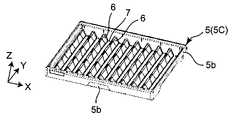
図18Aから図19Cを参照すると、格納トレー5には、比較的小型の返品薬剤2の格納に適した格納トレー5A(Sサイズ)と、中型の返品薬剤2の格納に適した格納トレー5B(Mサイズ)と、比較的大型の返品薬剤2の格納に適した格納トレー5B(Lサイズ)とがある。格納部500は、これら3種類の格納トレー5A~5Bを少なくとも1個備えている。個々の格納トレー5(5A~5C)は、図において上方が開口したトレー本体5aと、トレー本体5aの上端縁に設けられたフランジ状部5bとを備える。 18A to 19C, the
図20を併せて参照すると、トレー本体5aの底部には、返品薬剤供給装置1に奥行方向(Y方向)に延び、返品薬剤供給装置1の幅方向(X方向)に間隔をあけて配置された複数の突条(突部)6が設けられている。隣接する突条6間には、直線状の配置溝(凹部)7が形成されており、この配置溝7に返品薬剤2が収容される。図19A~図19Cを参照すれば明らかなように、3種類の格納トレー5A~5Bは、突条6の寸法(高さ及び幅)とピッチが異なるため、配置溝7の寸法(深さと幅)が異なる。この配置溝7の寸法の相違により、前述のように3種類の格納トレー5A~5Bは、格納するのに適した返品薬剤2の寸法が異なる。 Referring also to FIG. 20 , at the bottom of the
(払出部)
払出部600は搬送機構601を備える。搬送機構601は、図1に模式的に示す入口602から払出位置(格納部500の図において手前側の位置)まで払出トレー8を移動させて位置決めし、払出作業完了後の払出トレー8を図1に模式的に示す出口603から搬出する。(Payment department)
The
(返品薬剤の格納と払出の動作)
認識部300における認識完了後の返品薬剤2を格納部500に格納する動作と、格納部500から払出部600に払出位置に配置された払出トレーに払い出す動作とを説明する。(Operation of storage and dispensing of returned medicine)
The operation of storing the returned-
まず、格納動作を説明する。 First, the storage operation will be explained.
ラベル読取部302の返品薬剤2は、スカラー型ロボット800の吸着ノズル801により吸着保持される。吸着ノズル801により吸着保持された返品薬剤2に対して、少なくともその返品薬剤2の大きさに応じて、格納領域、すなわち格納時に占める範囲と格納位置(どの格納トレー8のどの位置に格納されるか)が設定される。本実施形態では、格納領域のうち格納時に占める範囲はその返品薬剤2の長さL1と幅Wに対応する。格納時に示す領域は、他の返品薬剤2と干渉しないためのマージンを含む。格納部500の複数の格納トレー5のうち、いずれの格納トレー5のいずれの配置溝7に吸着ノズル801により吸着保持されている返品薬剤2を配置可能かが検索される。この検索結果に応じ、返品薬剤2を配置する格納トレー5と配置溝7(返却薬剤2の格納位置)が決定される。1個の格納トレー5に着目すると、図20に示すように「3番」の配置溝7が既に返品薬剤2で埋まっている場合、それ以外の配置溝7が吸着ノズル801により吸着されている返品薬剤2を配置する格納位置の候補となる。例えば、「6番」の溝の場合、2個の返品薬剤2が既に配置されているが、これらの返品薬剤2間の長さが格納しようとしている返品薬剤2について前述した格納時に示す範囲以上であれば、吸着ノズル801により吸着保持されている返品薬剤2を配置する候補となり得る。 The returned
前述のように、ラベル読取部302での認識終了時には、返品薬剤2はラベル3が上向きとなる姿勢である。スカラー型ロボット800の吸着ノズル801は、ラベル3が上向きの姿勢を維持したままで、返品薬剤2を吸着保持して該当する格納トレー5の該当する配置溝7、つまり前述のように決定された決定された格納領域に返品薬剤2を移載する。 As described above, when recognition by the
図16及び図17を参照して説明したように、格納部500は保持枠502間に間隔Sを設けることができるように構成されている。従って、返品薬剤2を吸着保持したスカラー型ロボット800の吸着ノズル801は、多段位置された保持枠502のいずれに保持された格納トレー5に対しても、自由にアクセスし、吸着保持している返品薬剤2を載置できる。 As described with reference to FIGS. 16 and 17, the
また、図18A~図19Cを参照して説明したように、格納部500の格納トレー5には、サイズが異なる3種類の格納トレー5A~5Bが含まれている。従って、格納する返品薬剤2の大きさによる制約を受けずに、認識が終了した返品薬剤2を格納部500に収納できる。 Further, as described with reference to FIGS. 18A to 19C, the
格納部500に格納されている返品薬剤2に関し、制御装置1000は個々の返品薬剤2の識別情報と関連付けて、前述の格納領域、つまりいずれの格納トレー5のいずれの位置(配置溝7とのその配置溝7上での位置)に配置されているかを記憶している。また、制御装置1000は、個々の返品薬品2の識別情報と関連付けて、種類と使用期限を記憶している。 Regarding the returned
次に、払出作業を説明する。 Next, the dispensing work will be explained.
スカラー型ロボット800の吸着ノズル801は、格納部500の格納トレー5から返品薬剤2を吸着保持し、払出位置に配置された払出トレー8に移載する。 The
払出作業は、例えば電子カルテシステムである上位のシステム(HIS: Hospital Information System)から返品薬剤供給装置1が受信した処方データに基づいて実行される。前述のように、格納部500に格納された返品薬剤2の種類及び使用期限と識別情報とが関連付けて記憶され、かつ個々の返品薬剤供給装置1が格納部500のどこに配置されているかも識別情報と関連付けて記憶されている。具体的には、制御装置1000は、格納部500に格納された返品薬剤2の種類、使用期限、及び格納領域と、識別情報とを関連付けて記憶している薬品マスターを備える。しかも、前述のように、多段配置された格納トレー5間に間隔Sを設けることできるので、吸着ノズル801は、多段配置された格納トレー5のいずれに格納された返品薬剤2であっても、必要に応じて自由に吸着保持できる。従って、薬品マスターを参照した結果、処方データに含まれる薬剤が格納部500に格納されている返品薬剤2であることが確認できれば、処方データに応じて制約なく払い出すことができる。また、同一種類の薬剤のうち使用期限が近いものから払い出す等、処方データに応じて効率的な払出が可能である。さらに、薬品マスターを参照した結果、処方データに含まれる薬剤が格納部500に格納されていないこと確認できれば、必要な表示を制御盤1001のディスプレイ1002に表示する等の処理を実行できる。 The dispensing work is executed based on the prescription data received by the returned-goods
以上のように、本実施形態の返品薬剤供給装置1によれば、種類、形状、大きさ、使用期限等の性状が種々異なり、かつ非整列状態で供給された返品薬剤2を、自動的に認識して高い自由度を確保して格納でき、処方データに応じて自由に払い出すことができる。 As described above, according to the returned-goods
(薬剤の形状及び大きさの認識の詳細)
前述したように、認識部300の仮置き部301において、返品薬剤2の形状及び大きさが認識される(形状及び大きさの情報が取得される)。そのために、返品薬剤2は、図1及び図12に示すように、半透明板305の載置面305a(カメラ307側の平面)上に、その長手軸Aが載置面305aに対して平行になるように載置される。そして、半透明板305上に載置された返品薬剤2は、半透明板305の下方に配置された照明306によって光が下方から照射された状態で、半透明板305の上方に配置されたカメラ307によって撮影される。(Details of recognition of drug shape and size)
As described above, the
制御装置1000は、カメラ307によって撮影された画像に基づいて、返品薬剤2の形状及び大きさの情報を取得するように構成されている。すなわち、制御装置1000は、返品薬剤2の形状及び大きさを認識するための認識部として機能する。 The control device 1000 is configured to acquire information on the shape and size of the returned
制御装置1000はまた、返品薬剤2の形状及び大きさの情報を取得するために、返品薬剤2が写るカメラ307の画像を画像処理するように構成されている(画像処理部を有する)。カメラ307の画像に対する画像処理として、例えば、その画像に写る返品薬剤2の像のエッジを検出するためのエッジ検出処理と、画像を二値化(白黒化)する二値化処理とが行われる。エッジ検出処理された画像と二値化処理された画像とに基づいて、制御装置1000は、返品薬剤2の形状と大きさの情報を取得する。 The control device 1000 is also configured to image-process the image of the returned-
また、制御装置1000は、取得した返品薬剤2の形状に基づいて、その返品薬剤2の形状が返品薬剤供給装置1において取り扱い対象の薬剤の形状であるかを判定するように構成されている。 Further, the control device 1000 is configured to determine whether the shape of the returned-
返品トレー4を介して返却される返品薬剤2に、例えば、ラベル読取部302における無端ベルト308とローラ309との間に噛み込む形状の薬剤、スカラー型ロボット800が保持できない形状の薬剤、格納部500に格納できない形状の薬剤、すなわち返品薬剤供給装置1がその構造を原因として取り扱うことができない形状の薬剤が含まれる場合がある。一例として、袋体や箱体に収納された状態の薬剤、部分的に欠損している薬剤、ラベルが部分的に剥離している薬剤、部分的に剥離したラベルが他の薬剤に貼り付いた薬剤などが挙げられる。このような返品薬剤は、返品薬剤供給装置1ではその構造上取り扱うことができないので、取り扱い対象外の薬剤(非格納薬剤)として処理される。非格納薬剤は、前述のように非格納薬剤配置部400の非格納薬剤配置箱401,402を経て、非格納薬剤用の返品トレー4に戻される。 The returned
(薬剤の種類及び使用期限の認識の詳細)
前述したように、ラベル読取部302において、返品薬剤2の種類及び使用期限が認識される(種類及び使用期限の情報が取得される)。そのために、ラベル読取部302は、図13に示すように、返品薬剤2が載置される無端ベルト308と、無端ベルト308上に載置された返品薬剤2と当接し、その返品薬剤2をその軸線Aを中心として回転させるローラ309とを有する。また、ラベル読取部302は、無端ベルト308を駆動するベルト駆動部(図示せず)と、ローラ309を駆動するローラ駆動部(図示せず)とを有する。ベルト駆動部及びローラ駆動部は、例えばモータであって、制御装置1000によって制御される。(Details of Recognition of Drug Types and Expiration Dates)
As described above, the
図13を参照すると、ローラ309は、無端ベルト308の上方に間隔をあけて、例えば1mmの間隔をあけて配置されている。また、無端ベルト308の進行方向Fは、ローラ309の回転中心線Rcの延在方向(Y軸方向)に対して非直交に交差している。例えば、本実施形態の場合、ローラ309の回転中心線Rcの延在方向と無端ベルト308の進行方向Fとの間の角度は、5~15度の範囲である。 Referring to FIG. 13, the
無端ベルト308の進行方向Fは、その上に載置された返品薬剤2がローラ309に接近する方向である。一方、ローラ309の回転方向は、無端ベルト308との対向領域において、無端ベルト308の進行方向FのX方向成分に対して周速が逆方向になるような回転方向である。 The advancing direction F of the
また、本実施形態の場合、無端ベルト308とローラ309との対向領域において、無端ベルト308の移動速度とローラ309の回転速度が同一になるように、無端ベルト308及びローラ309は、制御装置1000によってベルト駆動部及びローラ駆動部を介して駆動制御されている。 In the case of the present embodiment, the
このような無端ベルト308とローラ309によれば、無端ベルト308上に載置された返品薬剤2は、無端ベルト308によって運ばれ、ローラ309に接触する。これにより、返品薬剤2は、ローラ309に当接した状態で維持され、X軸方向に関して位置決めされる。 With the
なお、返品薬剤2(特にアンプル2Aや樹脂アンプル2C)は、ローラ309に当接した状態のときにその基端2bがストッパ317に対向するような向きで、無端ベルト308上に直交ロボット700によって載置されるのが好ましい。仮にアンプル2Aや樹脂アンプル2Cの先端2a(頭部2d)がストッパ317側に位置する向きで無端ベルト308上に載置された場合、無端ベルト308の搬送が開始されることによってその胴部2cの基端2b側の角部が先にローラ309に接触し、その接触した反動によって無端ベルト308上で向きが変わり、その頭部2dが無端ベルト308とローラ309との間に入り込む可能性がある。したがって、返品薬剤2の頭部2dが無端ベルト308とローラ309との間に入り込む可能性がある場合には、その返品薬剤2は、ローラ309に当接した状態のときにその基端2bがストッパ317に対向するような向きで、無端ベルト308上に直交ロボット700によって載置されるのが好ましい。 The returned medicine 2 (particularly the
無端ベルト308の進行方向Fとローラ309の回転中心線Rcの延在方向とが非直交に交差するため、ローラ309に当接した後の返品薬剤2はローラ309にガイドされて該ローラ309の回転中心線Rcの延在方向(Y軸方向)に移動する。最終的には、返品薬剤2の軸線Aの延在方向の一端がストッパ317に当接し、それにより、返品薬剤2は、ローラ309の回転中心線Rcの延在方向(Y軸方向)に関して位置決めされる。その結果、返品薬剤2は、ラベル読取部302に対して位置決めされる。 Since the advancing direction F of the
無端ベルト308の進行方向Fとローラ309の回転中心線Rcの延在方向とが非直交に交差するような無端ベルト308に対するローラ309の配置およびストッパ317により、返品薬剤2は高精度に位置決めされた状態で維持される。 Returned
仮に、無端ベルト308の進行方向Fとローラ309の回転中心線Rcの延在方向とが直交する場合、ローラ309に当接した状態の返品薬剤2は、ローラ309の回転中心線Rcの延在方向に移動し、ストッパ317から離間する可能性がある。このことを考慮して、ストッパ317と返品薬剤2との当接状態を維持するために、無端ベルト308の進行方向Fとローラ309の回転中心線Rcの延在方向とが非直交に交差している。 If the advancing direction F of the
返品薬剤2が高精度に位置決めされた状態で維持されることにより、例えば、ラベル読取部302のカメラ311視野内に返品薬剤2が維持されるとともに、バーコードリーダ312の読取可能領域内に返品薬剤2のラベル3のバーコードがセットされて維持される。その結果、カメラ311とバーコードリーダ312による返品薬剤2の種類と使用期限に対して高い認識精度を確保することができる。 By maintaining the returned
制御装置1000は、カメラ311によって撮影されたラベル3が写る画像に基づいて、返品薬剤2の使用期限の情報を取得するように構成されている(ラベル3に記載されている使用期限を認識するOCR部を有する)。また、制御装置1000は、バーコードリーダ312が読み取ったバーコードに基づいて、返品薬剤2の種類の情報を取得するように構成されている。すなわち、制御装置1000は、返品薬剤2の種類及び使用期限を認識するための認識部一部として機能する。 The control device 1000 is configured to acquire information on the expiration date of the returned
前述したように、ラベル3に記載されているバーコードに返品薬剤2の種類及び使用期限の情報が含まれている場合(例えば、使用期限を示すバーコードがラベル3に印刷されている場合)、バーコードリーダ312が読み取ったバーコードにより、返品薬剤2の種類と使用期限とを含む情報を取得することが可能である。また、その結果として、カメラ311を省略することができる。 As described above, when the barcode printed on the
なお、前述したように、ローラ309によって返品薬剤2が回転されている状態でその返品薬剤2のラベル3から種類及び使用期限を認識するため、その認識に失敗する可能性がある。その対処として、例えば、認識の失敗が所定の回数に達するまでまたは認識作業を繰り返すことによって所定の時間が経過するまで(タイムアウトするまで)、認識作業を繰り返してもよい。例えば、カメラ311によって撮影された画像に写るラベル3に記載されている使用期限をOCR部が認識できない場合、新たな画像がカメラ311によって撮影される。その新たに撮影された画像に写るラベル3の使用期限に対してOCR部は認識作業を実行する。所定の回数(例えば18回)認識に失敗した場合またはタイムアウトした場合、その返品薬剤2は、ラベル3を読み取ることができない非格納薬剤として処理される(非格納薬剤配置部400の非格納薬剤配置箱401、402に格納される)。 As described above, since the type and expiration date are recognized from the
また、制御装置1000は、ラベル読取部302にセットされた返品薬剤2の外径に基づいて、ローラ309の回転速度を制御するように構成されている。 Also, the control device 1000 is configured to control the rotation speed of the
理由を説明すると、返品薬剤2の外径が相対的に小さく、ローラ309の回転速度が相対的に高速である場合、返品薬剤2の周速は高い。そのために、バーコードリーダ312が、返品薬剤2の外周面に貼り付けられたラベル3のバーコードを正確に読み取れない可能性がある。この対処として、制御装置1000は、返品薬剤2の外径が小さくなるにしたがって、ローラ309の回転速度が低下するようにローラ駆動部を制御する。このことを可能とするために、制御装置1000は、認識部300の仮置き部301のカメラ307の画像から取得した返品薬剤2の形状及び大きさ(軸線Aの延在方向の大きさ)に基づいて、返品薬剤2の外径を算出するように構成されている。 To explain the reason, when the outer diameter of the returned
(吸着位置の決定)
次に、図21から図23を参照して、仮置き部301のカメラ307で撮影された画像に基づいて、返品薬剤2の吸着位置(直交型ロボット700の吸着ノズル701とスカラー型ロボット800の吸着ノズル801で吸着される位置)を算出する方法を説明する。(Determination of adsorption position)
Next, referring to FIGS. 21 to 23, based on the image captured by the
図21を参照すると、バイアル2Bは、胴部2cからの頭部2dの突出量が比較的少なく、胴部2cと頭部2dの径の差も小さいので、長さ(全長L1)の概ね中間位置を吸着位置SPに設定すれば、吸着ノズル701,801で吸着した際に重量バランスは良好である。つまり、バイアル2Bの場合、全長L1の概ね中間位置を吸着位置SPに設定すれば、吸着ノズル701,801による保持が安定する。 Referring to FIG. 21, the
引き続き図21を参照すると、アンプル2Aは、胴部2cからの頭部2dの突出量が比較的大きく、胴部2cと頭部2dの径の差も大きいので、全長L1の概ね中間位置を吸着位置SPに設定すると、吸着ノズル701,801で吸着した際に重量バランスが良好でない。アンプル2Aの場合、全長L1ではなく、胴部2cの長さL2の概ね中間位置を吸着位置SPに設定すれば、吸着ノズル701,801で吸着した際に重量バランスは良好である。つまり、アンプル2Aの場合、胴部2cの長さL2の概ね中間位置を吸着位置SPに設定すれば、吸着ノズル701,801による保持が安定する。この点は、樹脂アンプル2Cの場合も同様である。 Continuing to refer to FIG. 21, in the
以上の理由から、仮置き部301のカメラ307で撮影された画像に基づいて、以下の手順により返品薬剤2の吸着位置SPが算出される。 For the above reasons, based on the image captured by the
まず、カメラ307で撮影された画像(返品薬剤2の平面視での画像)の外形輪郭に対する包絡線313が設定される(図22及び図23のステップ1)。また、この包絡線313から凸面度が算出される(図22及び図23のステップ1)。凸面度は包絡線313が直線で返品薬剤2を囲むことができる程、値が1に近づく。すなわち、凸面度の値(最大値は1)が大きい程、胴部2cと頭部2dの径の差が少なく、胴部2cと頭部2dをつなぐ首部の胴部2c及び頭部2dに対する径の差も小さいことを意味する。 First, an
算出された凸面度の値が、予め設定された閾値(例えば0.8~0.9の範囲で設定できる)以上であるならば、カメラ307で撮影した返品薬剤2は、バイアル2Bと推定できる形状を有すると判断できるので、全長L1の中間、かつ幅Wの中間を吸着位置SPに設定する(図22のステップ2)。 If the calculated convexity value is equal to or greater than a preset threshold value (which can be set in the range of 0.8 to 0.9, for example), the returned
算出された凸面度の値が、前述の予め設定された閾値未満であれば、カメラ307で撮影した返品薬剤2は、アンプル2A(あるいは樹脂アンプル2C)と推定できる形状を有すると判断できるので、胴部2aの長さL2の中間を吸着位置SPに設定するために、以下の処理を行う。 If the calculated convexity value is less than the preset threshold, it can be determined that the returned
まず、包絡線313と返品薬剤2の画像の外形輪郭との比較により、胴部2cと頭部2dとの間の首部(部分的に縮径している部分)に相当する、括れ部分314を抽出する(図23のステップ2)。 First, by comparing the
次に、抽出された括れ部分314を直線で囲む矩形領域315を作成する(図23のステップ3)。 Next, a
その後、返品薬剤2の画像の外形輪郭から矩形領域315を除去することで、2つの領域316a,316bを作成する(図23のステップ4)。これらの領域316a,316bは、返品薬剤2の画像の外形輪郭のち括れ部分314以外の領域に相当する。また、これらの領域316a,316bの一方が返品薬剤2の胴部2cに相当し、他方が頭部2dに相当する。領域316a,316bの面積を比較し、面積が大きい方(胴部2cに相当)を処理対象として残し、面積が小さい方(頭部2dに相当)を処理対象から除外する。この例では、領域316aの面積が領域316bの面積よりも大きいので、領域316aを処理対象として残す。 After that, by removing the
最後に、領域316aの長さL2’(アンプル2Aの胴部2cの長さL2に相当)の中間と幅W’(アンプル2Aの胴部2cの幅Wに相当)の中間を吸着位置SPに設定する(図23のステップ4)。 Finally, the midpoint between the length L2′ (corresponding to the length L2 of the
以上の手順により、仮置き部301のカメラ307で撮影された画像に基づいて、返品薬剤2を吸着ノズル701,801で安定して保持できる吸着位置SPを自動的に決定できる。 By the above procedure, based on the image photographed by the
(返品薬剤の形状等の認識から搬送までの処理)
次に、これまで説明してきた返品薬剤2の形状等の認識からその認識結果に基づく返品薬剤2の搬送までの流れの一例を、図24A及び図24Bを参照しながら説明する。(Processing from recognizing the shape, etc. of returned drugs to delivery)
Next, an example of the flow from the recognition of the shape of the returned-
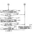
まず、ステップS101において、返品薬剤2が、直交型ロボット700によって認識部300の仮置き部301における半透明板305上に載置される。 First, in step S<b>101 , the returned
次に、ステップS102において、半透明板305上に載置された返品薬剤2が、その上方に配置されたカメラ307によって撮影される。 Next, in step S102, the returned
ステップS102で撮影されたカメラ307の画像は、ステップS103において、制御装置1000によって画像処理される(エッジ検出処理、二値化処理)。 The image captured by the
ステップS104において、制御装置1000は、ステップS103で画像処理されたカメラ307の画像に基づいて、仮置き部301の半透明板305上に載置された返品薬剤2の形状の情報を取得する。 In step S104, the control device 1000 acquires information on the shape of the returned
ステップS105において、制御装置1000は、ステップS104で取得した返品薬剤2の形状の情報に基づいて、仮置き部301の半透明板305上に載置された返品薬剤2の形状が取り扱い対象の薬剤の形状であるか否かを判定する。返品薬剤2の形状が取り扱い対象の薬剤の形状である場合にはステップS106に進み、そうでない場合(取り扱い対象外である場合)にはステップS115に進む。 In step S105, the control device 1000 determines that the shape of the returned-
ステップS106において、制御装置1000は、ステップS103で画像処理されたカメラ307の画像に基づいて、仮置き部301の半透明板305上に載置された返品薬剤2の大きさの情報を取得する。 In step S106, the control device 1000 acquires information on the size of the returned
ステップS107において、制御装置1000は、ステップS106で取得した返品薬剤2の大きさの情報に基づいて、仮置き部301の半透明板305上に載置された返品薬剤2の大きさが取り扱い対象の薬剤の大きさであるか否かを判定する。返品薬剤2の大きさが取り扱い対象の薬剤の大きさである場合にはステップS108に進み、そうでない場合(取り扱い対象外である場合)にはステップS115に進む。 In step S107, the control device 1000 determines that the size of the returned-
ステップS108において、仮置き部301の返品薬剤2は、直交型ロボット700によってラベル読取部302に搬送される。それにより、返品薬剤2は、ラベル読取部302にセットされる。 In step S<b>108 , the returned
ステップS109において、制御装置1000は、ステップS6で取得した返品薬剤2の大きさ(外径)に基づいて、返品薬剤2に当接して該返品薬剤2を回転させるラベル読取部302のローラ309の回転速度を調節する。 In step S109, based on the size (outer diameter) of the returned-
ステップS110において、制御装置1000は、返品薬剤2のラベル3がカメラ311やバーコードリーダ312によって正確に読み取り可能か否か判定する。ラベル3に記載された使用期限や返品薬剤2の種類を示すバーコードを正確に読み取れる場合にはステップS111に進む。例えば、使用期限やバーコードが部分的に消えているなど、これらを正確に読み取れない場合にはステップS115に進む。 In step S<b>110 , the control device 1000 determines whether or not the
ステップS111において、ラベル読取部302において返品薬剤2のラベル3が正確にカメラ311やバーコードリーダ312によって読み取られる。 In step S<b>111 , the
ステップS112において、制御装置1000は、ステップS111で読み取られた返品薬剤2のラベル3に基づいて、その返品薬剤2の種類及び使用期限の情報を取得する。 In step S112, the control device 1000 acquires information on the type and expiration date of the returned-
ステップS113において、制御装置1000は、ステップS112で取得した返品薬剤2の種類及び使用期限の情報に基づいて、ラベル読取部302にセットされた返品薬剤2の種類及び使用期限が取り扱い対象の薬剤の種類及び使用期限であるか否か判定する。すなわち、返品薬剤2の種類が薬品マスターに記憶されている種類であるか否かが判定されるとともに、使用期限が切れていないまたは使用期限が十分にあるか否かが判定される。返品薬剤2の種類及び使用期限の両方が取り扱い対象の薬剤のものである場合にはステップS114に進む。そうではない場合にはステップS115に進む。 In step S113, based on the information on the type and expiration date of the returned
ステップS114において、ラベル読取部302の返品薬剤2が、取り扱い対象の薬剤として、スカラー型ロボット800によって格納部500に搬送される。すなわち、形状、大きさ、種類、及び使用期限が取り扱い対象の薬剤の形状、大きさ、種類、及び使用期限である返品薬剤2が格納部500に格納される。 In step S114, the returned
ステップS115において、ステップS105で形状が取り扱い対象外の薬剤の形状と判定された返品薬剤2、ステップS107で大きさが取り扱い対象外の薬剤の大きさと判定された返品薬剤2、ステップ110でラベル3が読み取り不可能と判定された返品薬剤2、またはステップS113で種類及び使用期限の少なくとも一方が取り扱い対象外の薬剤のものと判定された返品薬剤2は、非格納薬剤として、非格納薬剤配置部400に搬送(格納)される。 In step S115, the returned
(変形例)
以下、上述の実施形態の種々の変形例を説明する。(Modification)
Various modifications of the above embodiment will be described below.
上述の実施の形態の場合、返品薬剤2は、取り扱い対象の薬剤である場合、返品トレー4から、認識部300の仮置き部301とラベル読取部302とを順に経て、格納部500の格納トレー5に格納される。これに代わって、返品薬剤2を、仮置き部301を介さずに、ラベル読取部302を経て格納部500に格納してもよい。 In the case of the above-described embodiment, when the returned
具体的に説明すると、仮置き部301は、返品トレー4を介して返品された返品薬剤2の形状及び大きさが返品薬剤供給装置1で取り扱うことができない形状及び大きさである場合を想定して設けられている。 More specifically, the
しかし、例えばユーザの周知が徹底している或いは薬剤メーカーから納品された箱を開封してすぐにその箱から薬剤を本装置に直接収納するなどして、返品トレー4を介して返品される返品薬剤2のほとんどが返品薬剤供給装置1の取り扱い対象の薬剤である場合、そのような返品薬剤2全てに対して仮置き部301にて形状及び大きさの認識を実行することは非常に無駄になる。 However, for example, if the user is thoroughly informed, or if the box delivered by the drug manufacturer is opened and the drug is directly stored in the device from the box immediately after opening, the returned drug is returned via the
その対処として、返品トレー4内の返品薬剤2は、まず、直交型ロボット700によって認識部300のラベル読取部302に移載される(その無端ベルト308上に載置される)。次に、無端ベルト308およびローラ309の駆動を開始する前に、カメラ311によって無端ベルト308上の返品薬剤2を撮影する。その撮影した画像に基づいて、無端ベルト308上の返品薬剤2の向きが認識される。その認識された向きについて、返品薬剤2の基端2bがストッパ317側に位置するような向きであるか否かが判定される。そうでない場合は、直交型ロボット700によってその向きが変更される。 As a countermeasure, the returned
なお、返品薬剤2の向きは、返品薬剤2が返却トレー4内に存在するとき、すなわちその返品トレー4が昇降部200のテーブル203上に載置されているときに、その返品トレー4の上方に位置するカメラ304が撮影した画像に基づいて認識することも可能である。カメラ304の画像に基づいて返品トレー4内の返品薬剤2の向きを認識し、その認識結果に基づいて、直交型ロボット700は、その返品薬剤2の基端2bがストッパ317側に位置するように該返品薬剤2をラベル読取部302の無端ベルト308上に載置する。 The direction of the returned
返品トレー4から直接ラベル読取部302に移送された返品薬剤2は、カメラ311及びバーコードリーダ312によりその種類及び使用期限が認識される。 The type and expiry date of the returned
認識された種類に基づいて、返品薬剤2の形状及び大きさの情報が取得される。具体的には、制御装置1000が、薬剤の種類、形状、及び大きさを関連付けして記憶するサイズ情報マスタを備える。このサイズ情報マスタに記憶されている情報を参照することにより、ラベル読取部302にて認識された返品薬剤2の種類に対応する形状及び大きさを制御装置1000は取得する。そして、その取得された形状及び大きさに基づいて、その返品薬剤2の格納部500における格納領域が決定される。 Information on the shape and size of the returned
ラベル読取部302にて認識された種類に対応する形状及び大きさの情報がサイズ情報マスタに存在しない場合、その形状及び大きさの情報を取得するために、ラベル読取部302の返品薬剤2が仮置き部301に移送される。そして、前述したように、仮置き部301にて返品薬剤2の形状及び大きさの情報が取得される。その取得された返品薬剤2の形状及び大きさの情報は、その返品薬剤2の種類と関連付けされてサイズ情報マスタに記憶される。また、その形状及び大きさに基づいて、その返品薬剤2の格納部500における格納領域が決定される。 If the shape and size information corresponding to the type recognized by the
なお、サイズ情報マスタに記憶されているまたは新しい返品薬剤2の種類、形状、及び大きさの関連付け情報を、例えばネット環境を介して、更新または追加できるようにしてもよい。例えばサプライヤから供給された薬剤の情報に基づいて、ネット環境に接続されたPC(パーソナルコンピュータ)を介して、サイズ情報マスタ内に、新たな返品薬剤2の種類、形状、及び大きさの関連付け情報を追加してもよい。これにより、ラベル読取部302から仮置き部301に返品薬剤2を移送し、その仮置き部301にて返品薬剤2の形状及び大きさの情報を取得する必要性がなくなる。または低くなる。 It should be noted that the association information of the type, shape, and size of the returned
格納トレーは、実施形態のものに限定されず、例えば、格納トレー5のトレー本体5aの底部に返品薬剤2を配置すると変形し、配置された返品薬剤2の位置と姿勢を維持するように変形可能な部材を配置してもよい。つまり、格納トレー5は、実施形態とは異なる方式で、返品薬剤2の向き及び姿勢が維持されるように平面的に格納できるものでもよい。また、図25に示すような、格納部500がそれぞれ返品薬剤2を配置可能な複数の段部9を備えていてもよい。 The storage tray is not limited to that of the embodiment, and for example, it deforms when the returned
実施形態では、直交型ロボット700とスカラー型ロボット800は、いずれも返品薬剤2を吸着ノズル701,802により保持する。しかし、これらのロボットは、吸着ではなく、機械的に返品薬剤2を解除可能に保持してもよい。 In the embodiment, both the
返品薬剤供給装置を例に本発明を説明したが、本発明は返品薬剤を対象とする薬剤供給装置に限定されない。つまり、受入部に供給される薬剤は、返品薬剤に限定されない。 Although the present invention has been described with reference to a returned medicine supply device, the present invention is not limited to a medicine supply device intended for returned medicines. In other words, the medicines supplied to the receiving section are not limited to returned medicines.
1 返品薬剤供給装置
2 返品薬剤
2a 先端
2b 基端
2c 胴部
2d 頭部
2A アンプル
2B バイアル
2C 樹脂アンプル
3 ラベル
4 返品トレー
4a トレー本体
4b フランジ状部
5,5A,5B,5C 格納トレー
5a トレー本体
5b フランジ状部
6 突条
7 配置溝
8 払出トレー
9 段部
100 受入部
101 ラック部材
101a レール溝
200 昇降部
201 直動ガイド
202 キャリッジ
203 テーブル
203a 底部
203b 側部
203c 端部
204 レール溝
205 直動ガイド
206 キャリッジ
207 フック
300 認識部
301 仮置き部
302 ラベル読取部
303 照明
304 カメラ
305 半透明板
306 照明
307 カメラ
308 無端ベルト
309 ローラ
310 照明
311 カメラ
312 バーコードリーダ
313 包絡線
314 括れ部分
315 矩形領域
316a,316b 領域
400 格納薬剤配置部
401,402 非格納薬剤配置箱
500 格納部
501 直動ガイド
502 保持枠
503 直動ガイド
504 キャリッジ
505 リフト部材
600 払出部
601 搬送機構
602 入口
603 出口
700 直交型ロボット
701 吸着ノズル
702 吸着パッド
703 Y軸ビーム
704 キャリッジ
705 X軸ビーム
706 キャリッジ
707 ヘッド
708 昇降ロッド
709 ブラケット
710 ばね
800 スカラー型ロボット
801 吸着ノズル
802 吸着パッド
803 直動ガイド
804 キャリッジ
805 X軸ビーム
806 ベース
807 第1アーム
808 第2アーム
809 ヘッド
810 ブラケット
811 ばね
812 バーコードリーダ
900 サポートトレー
901 ロッド
1000 制御装置
1001 制御盤
1002 ディスプレイREFERENCE SIGNS LIST 1 Returned drug supply device 2 Returned drug 2a Tip 2b Base end 2c Body 2d Head 2A Ampoule 2B Vial 2C Resin ampoule 3 Label 4 Returned goods tray 4a Tray body 4b Flanged part 5, 5A, 5B, 5C Storage tray 5a Tray body 5b Flange-shaped part 6 Projection 7 Arrangement groove 8 Payout tray 9 Step part 100 Receiving part 101 Rack member 101a Rail groove 200 Lifting part 201 Linear motion guide 202 Carriage 203 Table 203a Bottom part 203b Side part 203c End part 204 Rail groove 205 Linear motion Guide 206 Carriage 207 Hook 300 Recognition Part 301 Temporary Placement Part 302 Label Reading Part 303 Illumination 304 Camera 305 Translucent Plate 306 Illumination 307 Camera 308 Endless Belt 309 Roller 310 Illumination 311 Camera 312 Barcode Reader 313 Envelope 314 Constricted Part 315 Rectangular Area 316a, 316b region 400 stored drug placement unit 401, 402 non-stored drug placement box 500 storage unit 501 linear guide 502 holding frame 503 linear guide 504 carriage 505 lift member 600 delivery unit 601 transport mechanism 602 entrance 603 exit 700 orthogonal robot 701 Suction nozzle 702 Suction pad 703 Y-axis beam 704 Carriage 705 X-axis beam 706 Carriage 707 Head 708 Lifting rod 709 Bracket 710 Spring 800 Scalar type robot 801 Suction nozzle 802 Suction pad 803 Linear motion guide 804 Carriage 805 X-axis beam 806 Base 807 First Arm 808 Second Arm 809 Head 810 Bracket 811 Spring 812 Barcode Reader 900 Support Tray 901 Rod 1000 Control Device 1001 Control Panel 1002 Display
Claims (7)
Translated fromJapanese薬剤を格納する格納トレーと、
処方データに基づいて前記薬剤を前記格納トレーから払い出す、払出機構と
を備え、
前記格納トレーには、前記薬剤が取出可能に保持され、
前記格納トレーに格納された個々の前記薬剤についての種類と前記格納トレー内の位置とを関連付けた情報が記憶されており、
前記払出機構は、前記記憶された情報に基づいて、前記処方データに含まれる前記薬剤が前記格納トレーにあれば、当該薬剤を前記格納トレーから払い出し、
前記薬剤仕分装置は、
前記薬剤が格納された返品トレーと、
前記返品トレーを受け入れる受入部と
をさらに備え、
前記薬剤仕分装置は、前記返品トレーから前記薬剤を取り出して前記格納トレーに格納し、
前記薬剤仕分装置は、前記薬剤の軸線が延びる方向を認識する認識部をさらに備え、
前記薬剤仕分装置は、前記認識部で認識された前記薬剤の前記軸線が延びる方向が予め定められた方向となるように前記薬剤を前記格納トレーに格納するように構成されている、薬剤仕分装置。A drug sorting device,
a storage trayfor storing thedrug ;
a dispensing mechanism for dispensing the drug from the storage tray based on prescription data;
The storage tray holds the drug in a removable manner,
Information is stored that associates the type of each drug stored in the storage tray with the position in the storage tray,
If the medicine contained in the prescription data is in the storage tray, the dispensing mechanism dispenses the medicine from the storage tray based on the stored information,
The drug sorting device
a return tray in which the drug is stored;
a receiving portion for receiving the returned goods tray;
further comprising
The medicine sorting device retrieves the medicine from the return tray and stores it in the storage tray,
The medicine sorting device further comprises a recognition unit that recognizes the direction in which the axis of the medicine extends,
The medicine sorting device is configured to store the medicines in the storage tray such that the extending direction of the axis of the medicine recognized by the recognition unit is a predetermined direction. .
前記凹部には、前記凹部が延びる方向が前記軸線が延びる方向となるように前記薬剤を配置可能である、請求項1に記載の薬剤仕分装置。The storage tray comprises at least a pair of protrusions adjacent to each other and a recess formed between the pair of protrusions,
2. The medicine sorting device according to claim1 , wherein the medicine can be placed in the recess such that the direction in which the recess extends is the direction in which the axis extends.
前記移送部は、
前記受入部から前記薬剤を一つずつ別の動作で移送する第1移送部と、
前記薬剤を前記格納トレーに一つずつ別の動作で移送する第2移送部と
を備える、請求項1から3のいずれか1項に記載の薬剤仕分装置。furthercomprising a transfer unit that transfers the drugsone by one in a separate operation ;
The transfer section is
a first transfer unitthat transfers the drugs one by one from the receiving unit in a separate operation ;
4. The drug sorting apparatus according toany one of claims 1 to 3, further comprising: a second transfer sectionthat transfers the drugs to the storage tray one by one in a separate operation .
前記格納トレーの種類毎に格納するのに適した前記薬剤の長さ及び直径ないし幅が異なる、請求項1から請求項3のいずれか1項に記載の薬剤仕分装置。Equipped with a plurality of types of storage trays,
4. A medication sorting apparatus according to any one of claims 1 to3 , wherein thelength and diameter or width of the medications suitable for storage differ for each type of storage tray.
前記薬剤の軸線が延びる方向を認識部で認識し、
前記薬剤を、前記薬剤が取出可能に保持される格納トレーに、前記認識部で認識された前記薬剤の前記軸線が延びる方向が予め定められた方向となるように格納し、
前記格納トレーに格納された個々の前記薬剤についての種類と前記格納トレー内の位置とを関連付けた情報を記憶し、
前記記憶された情報に基づいて、前記処方データに含まれる前記薬剤が前記格納トレーにあれば、当該薬剤を前記格納トレーから払い出す、薬剤仕分方法。Receive the return tray containing the drug in the receiving unit,
recognizing the direction in whichthe drugaxis extends ,
storing the drug in a storage tray from which the drug is removably held sothat the extending direction of the axis of the drug recognized by the recognition unit is a predetermined direction ;
storinginformation that associates the type of each drug stored in the storage tray with the position in the storage tray;
A medicine sorting method, wherein if the medicine contained in the prescription data is in the storage tray, the medicine is dispensed from the storage tray based on the stored information.
Priority Applications (3)
| Application Number | Priority Date | Filing Date | Title |
|---|---|---|---|
| JP2022146469AJP7421142B2 (en) | 2014-05-09 | 2022-09-14 | Pharmaceutical sorting device |
| JP2023215941AJP7614534B2 (en) | 2014-05-09 | 2023-12-21 | Medicine sorting device |
| JP2024195999AJP7730062B2 (en) | 2014-05-09 | 2024-11-08 | Medicine sorting device |
Applications Claiming Priority (7)
| Application Number | Priority Date | Filing Date | Title |
|---|---|---|---|
| JP2014097933 | 2014-05-09 | ||
| JP2014097933 | 2014-05-09 | ||
| JP2014195845 | 2014-09-25 | ||
| JP2014195845 | 2014-09-25 | ||
| JP2014230991 | 2014-11-13 | ||
| JP2014230991 | 2014-11-13 | ||
| JP2019114006AJP7178709B2 (en) | 2014-05-09 | 2019-06-19 | Drug sorting device and drug sorting method |
Related Parent Applications (1)
| Application Number | Title | Priority Date | Filing Date |
|---|---|---|---|
| JP2019114006ADivisionJP7178709B2 (en) | 2014-05-09 | 2019-06-19 | Drug sorting device and drug sorting method |
Related Child Applications (1)
| Application Number | Title | Priority Date | Filing Date |
|---|---|---|---|
| JP2022146469ADivisionJP7421142B2 (en) | 2014-05-09 | 2022-09-14 | Pharmaceutical sorting device |
Publications (2)
| Publication Number | Publication Date |
|---|---|
| JP2021151511A JP2021151511A (en) | 2021-09-30 |
| JP7147925B2true JP7147925B2 (en) | 2022-10-05 |
Family
ID=54392609
Family Applications (6)
| Application Number | Title | Priority Date | Filing Date |
|---|---|---|---|
| JP2016518232AActiveJP6544351B2 (en) | 2014-05-09 | 2015-05-08 | Drug sorting apparatus and drug sorting method |
| JP2019114006AActiveJP7178709B2 (en) | 2014-05-09 | 2019-06-19 | Drug sorting device and drug sorting method |
| JP2021095792AActiveJP7147925B2 (en) | 2014-05-09 | 2021-06-08 | Drug sorting device and drug sorting method |
| JP2022146469AActiveJP7421142B2 (en) | 2014-05-09 | 2022-09-14 | Pharmaceutical sorting device |
| JP2023215941AActiveJP7614534B2 (en) | 2014-05-09 | 2023-12-21 | Medicine sorting device |
| JP2024195999AActiveJP7730062B2 (en) | 2014-05-09 | 2024-11-08 | Medicine sorting device |
Family Applications Before (2)
| Application Number | Title | Priority Date | Filing Date |
|---|---|---|---|
| JP2016518232AActiveJP6544351B2 (en) | 2014-05-09 | 2015-05-08 | Drug sorting apparatus and drug sorting method |
| JP2019114006AActiveJP7178709B2 (en) | 2014-05-09 | 2019-06-19 | Drug sorting device and drug sorting method |
Family Applications After (3)
| Application Number | Title | Priority Date | Filing Date |
|---|---|---|---|
| JP2022146469AActiveJP7421142B2 (en) | 2014-05-09 | 2022-09-14 | Pharmaceutical sorting device |
| JP2023215941AActiveJP7614534B2 (en) | 2014-05-09 | 2023-12-21 | Medicine sorting device |
| JP2024195999AActiveJP7730062B2 (en) | 2014-05-09 | 2024-11-08 | Medicine sorting device |
Country Status (7)
| Country | Link |
|---|---|
| US (1) | US10275977B2 (en) |
| EP (1) | EP3141237A4 (en) |
| JP (6) | JP6544351B2 (en) |
| KR (1) | KR102404991B1 (en) |
| CN (1) | CN106163485B (en) |
| TW (1) | TWI683659B (en) |
| WO (1) | WO2015170761A1 (en) |
Families Citing this family (15)
| Publication number | Priority date | Publication date | Assignee | Title |
|---|---|---|---|---|
| US9940439B2 (en)* | 2013-11-29 | 2018-04-10 | Atabak Reza Royaee | Method and device for identification and/or sorting of medicines |
| US10275977B2 (en)* | 2014-05-09 | 2019-04-30 | Yuyama Mgf. Co., Ltd. | Method and apparatus for sorting returned medicine based on size |
| KR20250105490A (en)* | 2017-04-14 | 2025-07-08 | 가부시키가이샤 유야마 세이사쿠쇼 | Drug sorting device, sorting container, and drug return method |
| JP6957312B2 (en)* | 2017-10-26 | 2021-11-02 | Phcホールディングス株式会社 | Chemical sorting device |
| JP7376786B2 (en)* | 2017-11-08 | 2023-11-09 | 株式会社湯山製作所 | Drug cassette handling device and drug dispensing device |
| CN109993888B (en)* | 2017-12-29 | 2024-04-26 | 山东新北洋信息技术股份有限公司 | Commodity arrangement method and commodity arrangement device |
| JP6798639B2 (en)* | 2018-03-09 | 2020-12-09 | 株式会社湯山製作所 | Tablet packaging device |
| TWI831775B (en)* | 2018-06-19 | 2024-02-11 | 日商湯山製作所股份有限公司 | Drug sorting device |
| CN108985634B (en)* | 2018-07-19 | 2021-06-25 | 江苏木盟智能科技有限公司 | Article distribution method, server and distribution robot |
| CN108875845B (en)* | 2018-07-26 | 2024-02-20 | 广东数相智能科技有限公司 | Medicine sorting device |
| US10872688B2 (en)* | 2018-07-30 | 2020-12-22 | Arxium, Inc. | Visual analysis pill dispenser |
| JP7088803B2 (en)* | 2018-10-15 | 2022-06-21 | Phcホールディングス株式会社 | Chemical orientation determination device, chemical orientation determination method, and chemical orientation determination program |
| JP7364234B2 (en)* | 2020-11-18 | 2023-10-18 | 株式会社トーショー | Drug sorting equipment and injection drug dispensing system |
| CN113060458A (en)* | 2021-03-12 | 2021-07-02 | 北京华兴长泰物联网技术研究院有限责任公司 | Automatic medicine taking mechanism, medicine discharging and selling machine and control method thereof |
| CN120092097A (en) | 2022-10-31 | 2025-06-03 | 日本精工株式会社 | Induction heating method and manufacturing method of annular component, annular component, bearing, induction heating device, bearing manufacturing method, vehicle manufacturing method, and mechanical equipment manufacturing method |
Citations (2)
| Publication number | Priority date | Publication date | Assignee | Title |
|---|---|---|---|---|
| JP2013215343A (en) | 2012-04-06 | 2013-10-24 | Central Uni Co Ltd | Apparatus and method for classifying returned drug |
| US20130325168A1 (en) | 2011-02-18 | 2013-12-05 | Jun-ho Kim | Automatic medicine warehousing and releasing management system and method of automatically warehousing and releasing medicines thereof |
Family Cites Families (31)
| Publication number | Priority date | Publication date | Assignee | Title |
|---|---|---|---|---|
| JPS5642224Y2 (en)* | 1977-11-29 | 1981-10-02 | ||
| JP2991398B2 (en)* | 1993-11-12 | 1999-12-20 | 株式会社トーショー | Preparation method of injection medicine |
| JP3860271B2 (en)* | 1997-01-20 | 2006-12-20 | 株式会社トーショー | Dispensing drug dispensing method |
| JPH10234824A (en)* | 1997-02-26 | 1998-09-08 | Yuyama Seisakusho:Kk | Medicine delivering apparatus and quantity input device |
| JPH10249771A (en)* | 1997-03-05 | 1998-09-22 | Kanto Auto Works Ltd | Work carrying device for press machine |
| JP4066276B2 (en)* | 1998-01-13 | 2008-03-26 | 株式会社トーショー | Medicine bag storage device |
| US7006893B2 (en)* | 1999-09-22 | 2006-02-28 | Telepharmacy Solutions, Inc. | Systems for dispensing medical products |
| JP4582846B2 (en)* | 2000-01-18 | 2010-11-17 | 株式会社トーショー | Chemical storage device |
| JP2004284600A (en) | 2003-03-19 | 2004-10-14 | Sefa Technology Kk | Cylindrical tray for labeling device |
| JP2004345837A (en)* | 2003-05-26 | 2004-12-09 | Central Uni Co Ltd | Storage device for medical treatment |
| US7123989B2 (en)* | 2003-07-01 | 2006-10-17 | Asteres, Inc. | System and method for providing a random access and random load dispensing unit |
| JP2005237713A (en)* | 2004-02-26 | 2005-09-08 | Tosho Inc | Drug dispenser |
| US7080755B2 (en)* | 2004-09-13 | 2006-07-25 | Michael Handfield | Smart tray for dispensing medicaments |
| US7930064B2 (en)* | 2004-11-19 | 2011-04-19 | Parata Systems, Llc | Automated drug discrimination during dispensing |
| US20060266763A1 (en)* | 2005-05-31 | 2006-11-30 | Katrin Svabo Bech | Automated medication dispensing apparatus |
| JP4891251B2 (en)* | 2005-10-18 | 2012-03-07 | 平田機工株式会社 | Suction head device |
| JP2007161453A (en) | 2005-12-15 | 2007-06-28 | Tsubakimoto Chain Co | Shelf position automatic teaching device |
| KR101248655B1 (en)* | 2007-10-23 | 2013-04-01 | 가부시키가이샤 유야마 세이사쿠쇼 | Drug delivery device |
| EP2143667B1 (en)* | 2008-07-11 | 2011-01-12 | Rowa Automatisierungssysteme GmbH | Storage device for bulk goods and corresponding method |
| JP5564868B2 (en)* | 2008-09-19 | 2014-08-06 | 株式会社湯山製作所 | Drug dispensing device |
| JP2010188483A (en)* | 2009-02-19 | 2010-09-02 | Ihi Corp | Conveying robot |
| JP5306093B2 (en)* | 2009-07-22 | 2013-10-02 | 株式会社トーショー | Chemical management system |
| JP2011078598A (en)* | 2009-10-07 | 2011-04-21 | Seiko Instruments Inc | Automatic medicine feeder |
| JP2011104188A (en) | 2009-11-19 | 2011-06-02 | Panasonic Corp | Medicine management device and method |
| ES2685772T3 (en)* | 2009-12-30 | 2018-10-11 | Jvm Co., Ltd. | Medication management system |
| CA2806813C (en)* | 2010-07-29 | 2018-07-10 | Tosho, Inc. | Tablet splitting apparatus |
| JP5196337B1 (en)* | 2011-04-28 | 2013-05-15 | 株式会社湯山製作所 | Drug inspection device and drug packaging device |
| JP6000195B2 (en)* | 2013-07-03 | 2016-09-28 | 株式会社トーショー | Tablet cassette |
| JP6190672B2 (en)* | 2013-09-05 | 2017-08-30 | パナソニックヘルスケアホールディングス株式会社 | Chemical sorting device, sorting tray for chemical sorting device |
| US10275977B2 (en)* | 2014-05-09 | 2019-04-30 | Yuyama Mgf. Co., Ltd. | Method and apparatus for sorting returned medicine based on size |
| AU2015301018B2 (en)* | 2014-08-05 | 2020-06-25 | Hero Health, Inc. | Dispensable unit retrieval mechanism, identification, and networked notification |
- 2015
- 2015-05-08USUS15/310,067patent/US10275977B2/enactiveActive
- 2015-05-08EPEP15789382.7Apatent/EP3141237A4/ennot_activeCeased
- 2015-05-08CNCN201580019463.5Apatent/CN106163485B/enactiveActive
- 2015-05-08KRKR1020167027898Apatent/KR102404991B1/enactiveActive
- 2015-05-08JPJP2016518232Apatent/JP6544351B2/enactiveActive
- 2015-05-08WOPCT/JP2015/063370patent/WO2015170761A1/enactiveApplication Filing
- 2015-05-08TWTW104114835Apatent/TWI683659B/enactive
- 2019
- 2019-06-19JPJP2019114006Apatent/JP7178709B2/enactiveActive
- 2021
- 2021-06-08JPJP2021095792Apatent/JP7147925B2/enactiveActive
- 2022
- 2022-09-14JPJP2022146469Apatent/JP7421142B2/enactiveActive
- 2023
- 2023-12-21JPJP2023215941Apatent/JP7614534B2/enactiveActive
- 2024
- 2024-11-08JPJP2024195999Apatent/JP7730062B2/enactiveActive
Patent Citations (2)
| Publication number | Priority date | Publication date | Assignee | Title |
|---|---|---|---|---|
| US20130325168A1 (en) | 2011-02-18 | 2013-12-05 | Jun-ho Kim | Automatic medicine warehousing and releasing management system and method of automatically warehousing and releasing medicines thereof |
| JP2013215343A (en) | 2012-04-06 | 2013-10-24 | Central Uni Co Ltd | Apparatus and method for classifying returned drug |
Also Published As
| Publication number | Publication date |
|---|---|
| JP2025016781A (en) | 2025-02-04 |
| WO2015170761A1 (en) | 2015-11-12 |
| JPWO2015170761A1 (en) | 2017-04-20 |
| CN106163485B (en) | 2022-09-09 |
| JP7421142B2 (en) | 2024-01-24 |
| EP3141237A1 (en) | 2017-03-15 |
| JP6544351B2 (en) | 2019-07-17 |
| JP7178709B2 (en) | 2022-11-28 |
| US10275977B2 (en) | 2019-04-30 |
| KR20170007248A (en) | 2017-01-18 |
| CN106163485A (en) | 2016-11-23 |
| KR102404991B1 (en) | 2022-06-07 |
| TWI683659B (en) | 2020-02-01 |
| US20170140601A1 (en) | 2017-05-18 |
| JP2019177184A (en) | 2019-10-17 |
| JP7614534B2 (en) | 2025-01-16 |
| TW201603804A (en) | 2016-02-01 |
| JP7730062B2 (en) | 2025-08-27 |
| JP2021151511A (en) | 2021-09-30 |
| EP3141237A4 (en) | 2017-12-27 |
| JP2022174235A (en) | 2022-11-22 |
| JP2024029074A (en) | 2024-03-05 |
Similar Documents
| Publication | Publication Date | Title |
|---|---|---|
| JP7147925B2 (en) | Drug sorting device and drug sorting method | |
| JP7307373B2 (en) | Drug recognition device and drug sorting device provided with the same | |
| JP7614552B2 (en) | Apparatus and program |
Legal Events
| Date | Code | Title | Description |
|---|---|---|---|
| A521 | Request for written amendment filed | Free format text:JAPANESE INTERMEDIATE CODE: A523 Effective date:20210707 | |
| A621 | Written request for application examination | Free format text:JAPANESE INTERMEDIATE CODE: A621 Effective date:20210707 | |
| A977 | Report on retrieval | Free format text:JAPANESE INTERMEDIATE CODE: A971007 Effective date:20220216 | |
| A131 | Notification of reasons for refusal | Free format text:JAPANESE INTERMEDIATE CODE: A131 Effective date:20220308 | |
| A521 | Request for written amendment filed | Free format text:JAPANESE INTERMEDIATE CODE: A523 Effective date:20220428 | |
| TRDD | Decision of grant or rejection written | ||
| A01 | Written decision to grant a patent or to grant a registration (utility model) | Free format text:JAPANESE INTERMEDIATE CODE: A01 Effective date:20220823 | |
| A61 | First payment of annual fees (during grant procedure) | Free format text:JAPANESE INTERMEDIATE CODE: A61 Effective date:20220905 | |
| R150 | Certificate of patent or registration of utility model | Ref document number:7147925 Country of ref document:JP Free format text:JAPANESE INTERMEDIATE CODE: R150 | |
| R250 | Receipt of annual fees | Free format text:JAPANESE INTERMEDIATE CODE: R250 |