JP7146811B2 - Reference detector element combined with anti-scatter collimator - Google Patents
Reference detector element combined with anti-scatter collimatorDownload PDFInfo
- Publication number
- JP7146811B2 JP7146811B2JP2019561303AJP2019561303AJP7146811B2JP 7146811 B2JP7146811 B2JP 7146811B2JP 2019561303 AJP2019561303 AJP 2019561303AJP 2019561303 AJP2019561303 AJP 2019561303AJP 7146811 B2JP7146811 B2JP 7146811B2
- Authority
- JP
- Japan
- Prior art keywords
- ray
- pixel
- pixels
- primary
- reference pixel
- Prior art date
- Legal status (The legal status is an assumption and is not a legal conclusion. Google has not performed a legal analysis and makes no representation as to the accuracy of the status listed.)
- Active
Links
Images


Classifications
- A—HUMAN NECESSITIES
- A61—MEDICAL OR VETERINARY SCIENCE; HYGIENE
- A61B—DIAGNOSIS; SURGERY; IDENTIFICATION
- A61B6/00—Apparatus or devices for radiation diagnosis; Apparatus or devices for radiation diagnosis combined with radiation therapy equipment
- A61B6/42—Arrangements for detecting radiation specially adapted for radiation diagnosis
- A61B6/4291—Arrangements for detecting radiation specially adapted for radiation diagnosis the detector being combined with a grid or grating
- A—HUMAN NECESSITIES
- A61—MEDICAL OR VETERINARY SCIENCE; HYGIENE
- A61B—DIAGNOSIS; SURGERY; IDENTIFICATION
- A61B6/00—Apparatus or devices for radiation diagnosis; Apparatus or devices for radiation diagnosis combined with radiation therapy equipment
- A61B6/06—Diaphragms
- A—HUMAN NECESSITIES
- A61—MEDICAL OR VETERINARY SCIENCE; HYGIENE
- A61B—DIAGNOSIS; SURGERY; IDENTIFICATION
- A61B6/00—Apparatus or devices for radiation diagnosis; Apparatus or devices for radiation diagnosis combined with radiation therapy equipment
- A61B6/42—Arrangements for detecting radiation specially adapted for radiation diagnosis
- A61B6/4208—Arrangements for detecting radiation specially adapted for radiation diagnosis characterised by using a particular type of detector
- A61B6/4233—Arrangements for detecting radiation specially adapted for radiation diagnosis characterised by using a particular type of detector using matrix detectors
- A—HUMAN NECESSITIES
- A61—MEDICAL OR VETERINARY SCIENCE; HYGIENE
- A61B—DIAGNOSIS; SURGERY; IDENTIFICATION
- A61B6/00—Apparatus or devices for radiation diagnosis; Apparatus or devices for radiation diagnosis combined with radiation therapy equipment
- A61B6/52—Devices using data or image processing specially adapted for radiation diagnosis
- A61B6/5205—Devices using data or image processing specially adapted for radiation diagnosis involving processing of raw data to produce diagnostic data
- A—HUMAN NECESSITIES
- A61—MEDICAL OR VETERINARY SCIENCE; HYGIENE
- A61B—DIAGNOSIS; SURGERY; IDENTIFICATION
- A61B6/00—Apparatus or devices for radiation diagnosis; Apparatus or devices for radiation diagnosis combined with radiation therapy equipment
- A61B6/58—Testing, adjusting or calibrating thereof
- A61B6/582—Calibration
- A61B6/585—Calibration of detector units
- G—PHYSICS
- G01—MEASURING; TESTING
- G01T—MEASUREMENT OF NUCLEAR OR X-RADIATION
- G01T1/00—Measuring X-radiation, gamma radiation, corpuscular radiation, or cosmic radiation
- G01T1/16—Measuring radiation intensity
- G01T1/161—Applications in the field of nuclear medicine, e.g. in vivo counting
- G01T1/164—Scintigraphy
- G01T1/1641—Static instruments for imaging the distribution of radioactivity in one or two dimensions using one or several scintillating elements; Radio-isotope cameras
- G01T1/1648—Ancillary equipment for scintillation cameras, e.g. reference markers, devices for removing motion artifacts, calibration devices
- G—PHYSICS
- G01—MEASURING; TESTING
- G01T—MEASUREMENT OF NUCLEAR OR X-RADIATION
- G01T1/00—Measuring X-radiation, gamma radiation, corpuscular radiation, or cosmic radiation
- G01T1/29—Measurement performed on radiation beams, e.g. position or section of the beam; Measurement of spatial distribution of radiation
- G01T1/2914—Measurement of spatial distribution of radiation
- G01T1/2921—Static instruments for imaging the distribution of radioactivity in one or two dimensions; Radio-isotope cameras
- G01T1/2928—Static instruments for imaging the distribution of radioactivity in one or two dimensions; Radio-isotope cameras using solid state detectors
- G—PHYSICS
- G21—NUCLEAR PHYSICS; NUCLEAR ENGINEERING
- G21K—TECHNIQUES FOR HANDLING PARTICLES OR IONISING RADIATION NOT OTHERWISE PROVIDED FOR; IRRADIATION DEVICES; GAMMA RAY OR X-RAY MICROSCOPES
- G21K1/00—Arrangements for handling particles or ionising radiation, e.g. focusing or moderating
- G21K1/02—Arrangements for handling particles or ionising radiation, e.g. focusing or moderating using diaphragms, collimators
- G21K1/025—Arrangements for handling particles or ionising radiation, e.g. focusing or moderating using diaphragms, collimators using multiple collimators, e.g. Bucky screens; other devices for eliminating undesired or dispersed radiation
- A—HUMAN NECESSITIES
- A61—MEDICAL OR VETERINARY SCIENCE; HYGIENE
- A61B—DIAGNOSIS; SURGERY; IDENTIFICATION
- A61B6/00—Apparatus or devices for radiation diagnosis; Apparatus or devices for radiation diagnosis combined with radiation therapy equipment
- A61B6/52—Devices using data or image processing specially adapted for radiation diagnosis
- A61B6/5258—Devices using data or image processing specially adapted for radiation diagnosis involving detection or reduction of artifacts or noise
- A61B6/5282—Devices using data or image processing specially adapted for radiation diagnosis involving detection or reduction of artifacts or noise due to scatter
Landscapes
- Health & Medical Sciences (AREA)
- Life Sciences & Earth Sciences (AREA)
- Engineering & Computer Science (AREA)
- Medical Informatics (AREA)
- Physics & Mathematics (AREA)
- High Energy & Nuclear Physics (AREA)
- Molecular Biology (AREA)
- Biomedical Technology (AREA)
- General Health & Medical Sciences (AREA)
- Nuclear Medicine, Radiotherapy & Molecular Imaging (AREA)
- Optics & Photonics (AREA)
- Pathology (AREA)
- Veterinary Medicine (AREA)
- Biophysics (AREA)
- Public Health (AREA)
- Radiology & Medical Imaging (AREA)
- Heart & Thoracic Surgery (AREA)
- Surgery (AREA)
- Animal Behavior & Ethology (AREA)
- Spectroscopy & Molecular Physics (AREA)
- General Physics & Mathematics (AREA)
- Computer Vision & Pattern Recognition (AREA)
- Mathematical Physics (AREA)
- General Engineering & Computer Science (AREA)
- Measurement Of Radiation (AREA)
- Apparatus For Radiation Diagnosis (AREA)
- Analysing Materials By The Use Of Radiation (AREA)
- Human Computer Interaction (AREA)
- Pulmonology (AREA)
- Theoretical Computer Science (AREA)
Description
Translated fromJapanese本明細書で開示される主題は、半導体ベースの検出器を含む、散乱防止グリッドを用いる検出器の使用に関する。 The subject matter disclosed herein relates to the use of detectors with anti-scatter grids, including semiconductor-based detectors.
非侵襲的撮像技術は、被検体(患者、製造品、手荷物、包装、または乗客)の内部構造または特徴の画像を非侵襲的に得ることを可能にする。特に、そのような非侵襲的撮像技術は、データを取得し、画像を構築し、場合によっては被検体の内部特徴を表すために、ターゲット体積を通るX線光子の差動透過または音波の反射などの様々な物理的原理に依存している。 Non-invasive imaging techniques allow images of internal structures or features of a subject (patient, article of manufacture, baggage, packaging, or passenger) to be obtained non-invasively. In particular, such non-invasive imaging techniques rely on the differential transmission of X-ray photons or the reflection of sound waves through a target volume to acquire data, construct an image, and possibly represent internal features of a subject. It depends on various physical principles such as
例えば、X線ベースの撮像技術では、X線放射線が人間の患者などの対象とする被検体に及び、放射の一部が検出器に衝突し、そこで強度データが収集される。デジタルX線システムでは、検出器は、検出器表面の個別の画素領域に衝突する放射線の量または強度を表す信号を発生する。その後、信号を処理して、検討のために表示することができる画像を生成することができる。 For example, in X-ray-based imaging techniques, X-ray radiation is directed onto a subject of interest, such as a human patient, and a portion of the radiation impinges on a detector where intensity data is collected. In a digital x-ray system, the detector produces signals representing the amount or intensity of radiation impinging on discrete pixel areas of the detector surface. The signal can then be processed to produce an image that can be displayed for review.
コンピュータ断層撮影(CT)として知られる1つのそのようなX線ベースの技法では、スキャナは、X線源からの扇形または円錐形のX線ビームを、患者などの撮像されている物体の周りの多数の視野角位置に投影し得る。X線ビームは、物体を横切るときに減衰され、検出器における入射X線強度の強度を表す信号を発生する一組の検出器素子によって検出される。信号は、処理されてX線経路に沿った物体の線形減衰係数の線積分を表すデータを発生する。これらの信号は、典型的には、「投影データ」または単に「投影」と呼ばれる。フィルタ補正逆投影法などの再構築技法を使用することによって、患者または撮像される物体の対象とする領域の体積または体積レンダリングを表す画像を生成することができる。医療の場面では、次に再構築された画像またはレンダリングされた体積から病状または他の対象とする構造を特定または識別することができる。 In one such X-ray based technique, known as computed tomography (CT), a scanner directs a fan or cone beam of X-rays from an X-ray source around an object being imaged, such as a patient. It can project to multiple viewing angle positions. The x-ray beam is attenuated as it traverses the object and is detected by a set of detector elements that produce a signal representing the intensity of the incident x-ray intensity at the detector. The signal is processed to generate data representing the line integral of the linear attenuation coefficient of the object along the x-ray path. These signals are typically called "projection data" or simply "projections". Reconstruction techniques, such as filtered backprojection, can be used to generate images representing volumes or volumetric renderings of regions of interest of the patient or imaged object. In a medical setting, pathologies or other structures of interest can then be identified or identified from the reconstructed image or rendered volume.
これらのタイプの撮像技法で使用される放射線検出器は、エネルギー積分モード(すなわち、取得間隔中に蓄積された全積分エネルギーの読み出し)または光子計数モード(各個々のX線光子が検出およびカウントされる)で動作することができる。エネルギー積分は、ほとんどの臨床用途におけるX線検出器の従来のモードである。しかしながら、光子計数検出器は、分解能の向上、コントラスト対ノイズ比を改善する可能性、X線ビーム中の材料をより良好に描写する可能性など、エネルギー積分検出器と比較して他の利点を提供する。 Radiation detectors used in these types of imaging techniques are either in energy integration mode (i.e. readout of the total integrated energy accumulated during the acquisition interval) or photon counting mode (where each individual X-ray photon is detected and counted). ). Energy integration is the conventional mode of X-ray detectors in most clinical applications. However, photon-counting detectors offer other advantages compared to energy-integrating detectors, such as increased resolution, potential for improved contrast-to-noise ratio, and potential for better delineation of materials in the X-ray beam. offer.
多くの場合、放射線源に面する検出器の表面付近または表面上に散乱防止グリッド(例えば、コリメータ)を用いることができる。散乱防止グリッドは、物体による散乱などにより、検出器への直線の経路を進行していないX線光子の影響を低減または排除するのに有用であり得る。しかしながら、そのような散乱防止グリッドの存在の結果は、散乱防止グリッドの下にある検出器のそれらの部分における検出器の利用可能な検出表面の損失となる。 In many cases, an anti-scatter grid (eg, a collimator) can be used near or on the surface of the detector facing the radiation source. An anti-scatter grid can be useful to reduce or eliminate the effects of X-ray photons that do not travel a straight line path to the detector, such as due to scattering by objects. However, the result of the presence of such an anti-scatter grid is a loss of available detection surface of the detector in those portions of the detector that underlie the anti-scatter grid.
一実施形態では、放射線検出器が提供される。この実施形態によれば、放射線検出器は、一次元または二次元の幾何学的形状に配置されたX線減衰隔壁を備える散乱防止コリメータと、放射線検出器パネルとを含む。放射線検出器パネルは、散乱防止コリメータの隔壁の下方にならないように位置決めされた一次画素のアレイ、および1つまたは複数のそれぞれの一次画素に隣接し、それぞれの隔壁または隔壁の交差部の下方に位置決めされた少なくとも1つの基準画素を含む。 In one embodiment, a radiation detector is provided. According to this embodiment, the radiation detector includes an anti-scatter collimator comprising x-ray attenuating partitions arranged in a one-dimensional or two-dimensional geometry, and a radiation detector panel. A radiation detector panel comprises an array of primary pixels positioned so as not to be below the septum of the anti-scatter collimator, and one or more adjacent each primary pixel and below each septum or intersection of septa. It includes at least one positioned reference pixel.
さらなる実施形態では、検出器に対するX線焦点の位置を測定するための方法が提供される。この実施形態によれば、検出器パネルの1つまたは複数の基準画素から読み出された信号は、信号パターンについて分析される。1つまたは複数の基準画素は、検出器パネルに近接して位置決めされた散乱防止コリメータのX線減衰隔壁または隔壁交差部の下方に位置決めされる。信号パターンが検出されない場合、補正措置は取られない。信号パターンが検出される場合、X線焦点の位置は、信号パターンに基づいて推定される。 In a further embodiment, a method is provided for measuring the position of the x-ray focus relative to the detector. According to this embodiment, signals read out from one or more reference pixels of the detector panel are analyzed for signal patterns. One or more reference pixels are positioned below the x-ray attenuating septum or septum intersection of an anti-scatter collimator positioned proximate to the detector panel. If no signal pattern is detected, no corrective action is taken. If a signal pattern is detected, the position of the x-ray focus is estimated based on the signal pattern.
追加の実施形態では、撮像システムが提供される。この実施形態によれば、撮像システムは、動作中に焦点からX線光子を放出するように構成されたX線源と、放射線検出器アセンブリとを含む。放射線検出器アセンブリは、X線減衰隔壁を備える散乱防止コリメータ、および放射線検出器パネルとを含む。放射線検出器パネルは、散乱防止コリメータの隔壁の下方にならないように位置決めされた一次画素のアレイと、それぞれの隔壁または隔壁の交差部の下方に位置決めされた1つまたは複数の基準画素とを含む。撮像システムは、電荷共有事象が発生したとき、1つまたは複数の基準画素およびそれぞれの一次画素からの信号を組み合わせるように構成された読み出し電子回路をさらに含む。 In an additional embodiment, an imaging system is provided. According to this embodiment, an imaging system includes an X-ray source configured to emit X-ray photons from a focal point during operation, and a radiation detector assembly. The radiation detector assembly includes an anti-scatter collimator with x-ray attenuating septa, and a radiation detector panel. The radiation detector panel includes an array of primary pixels positioned so as not to be below the septum of the anti-scatter collimator and one or more reference pixels positioned below each septum or intersection of the septa. . The imaging system further includes readout electronics configured to combine signals from the one or more reference pixels and the respective primary pixels when a charge sharing event occurs.
本発明のこれらおよび他の特徴、態様、および利点は、添付の図面を参照しながら以下の詳細な説明を読解すればより良好に理解され、添付の図面においては、図面全体を通して同一の符号は同一の部分を表している。 These and other features, aspects and advantages of the present invention will be better understood upon reading the following detailed description with reference to the accompanying drawings, in which like reference numerals refer to represent the same part.
1つまたは複数の具体的な実施形態を、以下に記載する。これらの実施形態の簡潔な説明を提供しようと努力しても、実際の実施態様におけるすべての特徴を本明細書に記載できるわけではない。エンジニアリングまたは設計プロジェクトなどの実際の実施態様の開発においては、開発者の特定の目的を達成するために、例えばシステム関連および事業関連の制約条件への対応など実施態様に特有の決定を数多くしなければならないし、また、これらの制約条件は実施態様ごとに異なる可能性があることを理解されたい。さらに、このような開発努力は、複雑で時間がかかるが、それでもなお本開示の利益を有する当業者にとっては、設計、製作、および製造の日常的な仕事であることを理解されたい。 One or more specific embodiments are described below. Despite an effort to provide a concise description of these embodiments, not all features of an actual implementation may be described herein. In the development of an actual implementation, such as an engineering or design project, many implementation-specific decisions, such as meeting system-related and business-related constraints, must be made to achieve the developer's specific objectives. and that these constraints may vary from implementation to implementation. Further, it should be understood that such development efforts, while complex and time consuming, are nevertheless routine tasks of design, fabrication, and manufacture for those skilled in the art having the benefit of this disclosure.
本発明の様々な実施形態の要素を紹介するとき、「1つの(a、an)」、「この(the)」、および「前記(said)」という冠詞は、それらの要素が1つまたは複数存在することを意味するものとする。「備える(comprising)」、「含む(including)」、および「有する(having)」という用語は、包括的であることを意図し、列挙された要素以外にもさらなる要素が存在してもよいことを意味する。さらに、以下の説明におけるあらゆる数値例は非限定的なものであることを意図し、したがって追加の数値、範囲、および百分率は開示される実施形態の範囲内にあるものとする。 When introducing elements of various embodiments of the present invention, the articles "a, an," "the," and "said" refer to one or more of those elements. exist. The terms "comprising," "including," and "having" are intended to be inclusive and indicate that there may be additional elements other than the listed elements. means Furthermore, any numerical examples in the following description are intended to be non-limiting, and thus additional numerical values, ranges, and percentages are intended to be within the disclosed embodiments.
以下の説明は一般に医療撮像の場面で提供されるが、本技法は、そのような医療の場面に限定されないことを理解されたい。実際に、そのような医療の場面における例および説明の提供は、現実の実施態様および用途の事例を提供することによって説明を容易にすることに過ぎない。しかしながら、本手法は、製造された部品または商品の非破壊検査(すなわち、品質管理または品質検討用途)、および/または包装、箱、荷物の非侵襲的検査など(すなわち、セキュリティまたはスクリーニング用途)、他の場面でも利用することができる。一般に、本手法は、光子計数の場面におけるエネルギー弁別が望ましい、任意の撮像またはスクリーニングの場面において望ましい可能性がある。 Although the following description is generally provided in the context of medical imaging, it should be understood that the techniques are not limited to such medical settings. Indeed, providing examples and explanations in such medical contexts merely facilitates the explanation by providing examples of actual implementations and applications. However, the present techniques are not suitable for non-destructive inspection of manufactured parts or goods (i.e. quality control or quality review applications), and/or non-invasive inspection of packages, boxes, packages, etc. (i.e. security or screening applications), It can also be used in other situations. In general, this approach may be desirable in any imaging or screening scenario where energy discrimination in photon counting scenarios is desired.
本明細書で説明するように、本手法は、グリッドとして形成され得る散乱防止コリメータの隔壁の下に存在する検出器セルまたは素子(すなわち、基準検出器セルまたは画素)の使用に関する。そのような手法は、本明細書で説明するように、典型的にはX線光子によって直接照射されない基準検出器セルを用いて、本明細書では活性または読み出し画素とも呼ばれる直接変換検出器の隣り合う一次(すなわち、照射される)画素からの電荷共有事象を補正することを可能にする。つまり、基準検出器がコリメータの下にあるため、一次信号はブロックされる。したがって、基準検出器によって検出される信号は、隣り合う一次または照射される画素に起因し得る電荷共有事象から主に発生する。このようにして、直接変換原理を使用して動作する室温半導体(例えば、ケイ素ベース、テルル化カドミウムベースなど)検出器などの放射線検出器は、一次検出事象によって生成された信号を補足する基準信号を生成し得る。 As described herein, the present approach involves the use of detector cells or elements (ie, reference detector cells or pixels) that underlie the septum of the anti-scatter collimator, which may be formed as a grid. Such an approach, as described herein, typically employs a reference detector cell that is not directly illuminated by X-ray photons, and is next to a direct conversion detector, also referred to herein as an active or readout pixel. Allows to correct for charge sharing events from matching primary (ie illuminated) pixels. That is, the primary signal is blocked because the reference detector is below the collimator. Thus, the signal detected by the reference detector primarily arises from charge-sharing events that can be attributed to adjacent primary or illuminated pixels. In this way, radiation detectors, such as room temperature semiconductor (e.g., silicon-based, cadmium telluride-based, etc.) detectors that operate using the direct conversion principle, generate a reference signal that complements the signal produced by the primary detection event. can generate
加えて、コリメータの影にあるため、基準検出器セルからの信号は、焦点と検出器との間の相対運動に敏感である。つまり、基準検出器セルに対する焦点の移動またはぐらつきは、コリメータがX線光子をブロックするかどうかを決定する場合がある。本明細書で説明するように、相対運動に対するこの感度は、コリメータと源の相対位置を較正するために、または基準検出器セルからの信号の直接フィードバックに基づいてリアルタイムで焦点の位置を調整するために使用することができる。 In addition, being in the shadow of the collimator, the signal from the reference detector cell is sensitive to relative motion between the focal spot and the detector. That is, movement or wobble of the focus relative to the reference detector cell may determine whether the collimator blocks X-ray photons. As described herein, this sensitivity to relative motion can be used to calibrate the relative positions of the collimator and source, or to adjust the position of the focal spot in real time based on direct feedback of the signal from the reference detector cell. can be used for
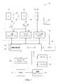
前述の説明を念頭に置いて、図1は、本明細書で説明される構造および手法に従って、散乱防止グリッドまたはコリメータの隔壁の下方に位置する基準検出器セルを使用して画像データを取得および処理するための撮像システム10の一実施形態を示す。図示の実施形態では、システム10は、X線投影データを取得し、表示および分析のために投影データを体積再構築に再構築するように設計されたコンピュータ断層撮影(CT)システムである。CT撮像システム10は、撮像セッション中に1つまたは複数のエネルギースペクトルでのX線生成を可能にする1つまたは複数のX線管または固体放出構造など、1つまたは複数のX線源12を含む。 With the foregoing discussion in mind, FIG. 1 illustrates image data acquisition and detection using a reference detector cell located below a septum of an anti-scatter grid or collimator according to the structures and techniques described herein. 1 illustrates one embodiment of
特定の実施態様では、源12は、X線ビーム20の高強度領域の形状および/もしくは範囲を画定するため、X線ビーム20のエネルギープロファイルを制御もしくは画定するため、ならびに/または場合によっては対象とする領域内にない患者24の部分へのX線露光を制限するために、X線ビーム20を操縦するために使用され得るフィルタアセンブリもしくはビーム整形器22に近接して位置決めされてもよい。実際には、フィルタアセンブリまたはビーム整形器22は、源12と撮像体積との間でガントリ内に組み込まれてもよい。 In certain embodiments, the
X線ビーム20は、被検体(例えば、患者24)または対象とする物体(例えば、製造された構成要素、手荷物、包装など)が位置決めされる領域に進入する。被検体は、X線光子20の少なくとも一部を減衰させることで減衰されたX線光子26をもたらし、これは、本明細書で説明されるように複数の検出器素子(例えば、画素)によって形成された検出器アレイ28に作用する。検出器28は、エネルギー積分検出器、光子計数検出器、エネルギー弁別検出器、または任意の他の適切な放射線検出器であってもよい。例として、検出器28は、エネルギー弁別光子計数検出器であってもよく、その出力は、測定位置においてスキャンまたは撮像セッションに対応する時間間隔にわたって検出器に衝突する光子の数およびエネルギーに関する情報を伝える。一実施形態では、検出器28は、半導体センサ自体がX線光子に曝されたときに測定可能な信号を生成する、ケイ素ストリップまたは他の半導体材料に基づく検出器など、直接変換型の検出器(すなわち、シンチレータ手段を用いない検出器)であってもよい。
図示の例では、検出器28は、典型的にはX線光子を吸収するか、場合によってはブロックする材料で作られる散乱防止コリメータ18に隣接するか、場合によっては近接している。したがって、散乱防止コリメータ18の隔壁に当たるX線光子は、物体24によって反射または偏向された後、場合によっては散乱防止コリメータ18の隔壁に対してある角度で移動した後、検出器28に達することが防止される。逆に、X線源12から検出器28まで比較的直線の経路を進行するX線光子は、散乱防止コリメータ18によって妨げられず、検出器28に達する。これらの光子のごく一部は、散乱防止コリメータの断面に当たって減衰される。本明細書における説明の目的のために、検出器28は、ある場合には、X線源12の視点から見て散乱防止コリメータ18の下方または「影」にあると呼ばれることがある。そのような特徴描写は、コリメータ18が常にX線源12と検出器28との間にあり、X線源12が(実際の向きまたは位置に関係なく)「上」であり、X線照射源として見られる関係を示す。しかしながら、理解されるように、そのような特徴描写は、絶対的な位置または向きの情報を必ずしも示すものではない。 In the illustrated example, the
検出器28に関して、本明細書で説明するように、検出器28は、典型的には、検出器素子のアレイを画定し、各素子は、X線光子に曝されると電気信号を発生する。電気信号は、1つまたは複数の投影データセットを生成するために取得および処理される。図示の例では、検出器28は、システムコントローラ30に結合され、システムコントローラ30は、検出器28によって生成されたデジタル信号の取得を指示する。 With respect to
システムコントローラ30は、フィルタ処理、検査および/または較正プロトコルを実施するように撮像システム10の動作を指示し、取得されたデータを処理することができる。X線源12に関して、システムコントローラ30は、X線検査シーケンスのために電力、焦点場所、制御信号などを供給する。特定の実施形態によれば、システムコントローラ30は、フィルタアセンブリ22、CTガントリ(またはX線源12および検出器28が取り付けられる他の構造的支持体)、ならびに/または検査の過程にわたる患者支持体の並進および/もしくは傾斜の動作を制御し得る。 System controller 30 may direct operation of
加えて、システムコントローラ30は、モータコントローラ36を介して、それぞれ被検体24および/または撮像システム10の構成要素を移動させるために使用される直線位置決めサブシステム32および/または回転サブシステム34の動作を制御することができる。システムコントローラ30は、信号処理回路および関連するメモリ回路を含むことができる。そのような実施形態では、メモリ回路は、X線源12および/またはフィルタアセンブリ22を含む撮像システム10を動作させ、本明細書で説明されるステップおよびプロセスに従って、検出器28によって取得されたデジタル測定値を処理するためにシステムコントローラ30によって実施されるプログラム、ルーチン、および/または符号化アルゴリズムを記憶し得る。一実施形態では、システムコントローラ30は、プロセッサベースのシステムの全部または一部として実装することができる。 In addition, system controller 30, via
源12は、システムコントローラ30内に含まれるX線コントローラ38によって制御することができる。X線コントローラ38は、電力、タイミング信号、および/または焦点サイズおよびスポット場所を源12に提供するように構成することができる。加えて、いくつかの実施形態では、X線コントローラ38は、システム10内の異なる場所にある管またはエミッタが互いに同期して、もしくは互いに独立して動作することができるように源12を選択的に作動させ、または撮像セッション中に異なるエネルギープロファイル間で源を切り替えるように構成され得る。
システムコントローラ30は、データ取得システム(DAS)40を含むことができる。DAS40は、検出器28からのデジタル信号など、検出器28の読み出し電子回路によって収集されたデータを受け取る。次に、DAS40は、コンピュータ42などのプロセッサベースのシステムによる後続の処理のためにデータを変換および/または処理することができる。本明細書で説明される特定の実施態様では、検出器28内の回路は、データ取得システム40への送信前に検出器のアナログ信号をデジタル信号に変換することができる。コンピュータ42は、コンピュータ42によって処理されたデータ、コンピュータ42によって処理されるべきデータ、またはコンピュータ42の画像処理回路44によって実施される命令を記憶することができる1つまたは複数の非一時的メモリデバイス46を含むかまたはそれらと通信することができる。例えば、コンピュータ42のプロセッサは、メモリ46に記憶された1つまたは複数の命令のセットを実施することができ、メモリ46は、コンピュータ42のメモリ、プロセッサのメモリ、ファームウェア、または同様のインスタンス化であってもよい。 System controller 30 may include a data acquisition system (DAS) 40 .
コンピュータ42はまた、オペレータワークステーション48を介してオペレータによって提供される指示およびスキャンパラメータに応答してなど、システムコントローラ30によって可能にされる特徴(すなわち、スキャン動作およびデータ収集)を制御するように適合することができる。システム10はまた、オペレータが関連するシステムデータ、撮像パラメータ、生の撮像データ、再構築データ(例えば、軟組織画像、骨画像、セグメント化された血管樹など)、材料基礎画像、および/または材料分解結果などを見ることを可能にするオペレータワークステーション48に結合されたディスプレイ50を含むことができる。加えて、システム10は、オペレータワークステーション48に結合され、任意の所望の測定結果を印刷するように構成されたプリンタ52を含むことができる。ディスプレイ50およびプリンタ52はまた、(図1に示すように)直接またはオペレータワークステーション48を介してコンピュータ42に接続されてもよい。さらに、オペレータワークステーション48は、画像保管通信システム(PACS)54を含むか、またはそれに結合することができる。PACS54は、遠隔システムまたはクライアント56、放射線科情報システム(RIS)、病院情報システム(HIS)、または内部もしくは外部のネットワークに結合することができ、そのようにして様々な場所の第三者が画像データにアクセスすることができる。
撮像システム10全体の前述の説明を念頭に置いて、本手法は、電荷共有および/または焦点補正などの様々な目的のために散乱防止コリメータ18の下方から測定された信号を利用する。これは、散乱防止コリメータ18の下方の検出器領域(例えば、画素)が非活性化されているか、場合によっては読み出しも利用もされていない従来の技法と対照的である。 With the foregoing description of the
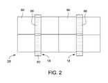
本手法では、散乱防止グリッド隔壁に対応する面積の下方の検出器素子(例えば、画素)は、対応する検出器素子または画素を有する基準検出器として示される。これは、一次元(1D)散乱防止コリメータ18(図2)および二次元(2D)散乱防止コリメータ18(図3)について概念的に示されている。これらの例では、検出器28の一次(すなわち、活性または読み出し)画素80(例えば、500μm×500μm画素または1mm×1mm画素)のアレイが画定されている。一次画素は、スキャンの一部として画像を生成するために処理される投影データの生成に使用される画素である。複数の隔壁82によって画定された散乱防止コリメータ18は、検出器28に隣接して、場合によっては近接して(例えば、上に)設けられる。隔壁82の下の検出器28の面積は、一般に、入射X線光子から遮蔽されている。 In this approach, detector elements (eg, pixels) below the area corresponding to the anti-scatter grid partition are denoted as reference detectors with corresponding detector elements or pixels. This is illustrated conceptually for a one-dimensional (1D) anti-scatter collimator 18 (FIG. 2) and a two-dimensional (2D) anti-scatter collimator 18 (FIG. 3). In these examples, an array of primary (ie, active or readout) pixels 80 (eg, 500 μm×500 μm pixels or 1 mm×1 mm pixels) of
しかしながら、これらの例では、基準検出器画素86(すなわち、基準検出器)は、各一次画素80に隣接する隔壁(82)の下方に設けられる。散乱防止グリッドの隔壁は、有用な信号を最大化するように、一次画素面積に対して比較的狭い断面積を有するので、基準検出器画素の面積は、対応する一次画素面積よりも小さい。 However, in these examples, a reference detector pixel 86 (ie, a reference detector) is provided below the septum (82) adjacent each
基準検出器画素86および一次画素80からの信号は、検出器パネルおよび/またはDASの別々の読み出し回路(例えば、特定用途向け集積回路-ASIC)を使用するなど、別々に読み出すことができ、または同じ読み出し回路を使用して読み出し、制御ロジックに基づいて別々に処理することができる。基準検出器画素から読み取られた信号と一次画素の信号との組合せまたは加算など、本明細書で説明する特定の動作では、そのような組合せまたは加算機能が読み出し回路またはASICに提供され得る。基準画素86から読み出された信号は、本明細書で説明するように、様々な目的に使用され得る。例として、基準画素86からの信号は、焦点の動きの検出/補正または電荷共有補正の一方または両方に使用されてもよい。 The signals from the
例として、図4を参照すると、散乱防止コリメータ18の隔壁82の下にある基準画素86を有する検出器28の側面図が示されている。この例では、X線源12からのX線放出に対応する焦点は、整列位置(焦点90A)および未整列位置(焦点90B)で示されている。そのような焦点の動きに関して、特定の撮像システムでは、焦点位置は、X線管温度の関数のように、x次元(すなわち、横方向)に±25μmおよび/またはz次元(すなわち、縦方向)に150μm以上移動する場合がある。焦点90の未整列または不整列は、システムの現在の較正の欠如などにより、意図的でないこと、または改善された投影データサンプリングのためにX線源で焦点のぐらつきを用いるスキャン手法の使用などにより、意図的なものであり得ることに留意されたい。 By way of example, referring to FIG. 4, a side view of
図4に示すように、焦点が整列位置にあるとき、X線光子26は、散乱防止コリメータ18の隔壁82によって基準検出器画素86に達するのをブロックされ、したがって信号を生成しない。逆に、焦点が整列からオフセットされると、X線光子26は、基準検出器画素86に達することができ、入射X線光子26に応じて信号を生成する。このようにして、基準検出器画素86によって生成された信号を使用して、スキャン中の焦点の移動を追跡することができ、スキャン中に焦点位置の調整係数(1つまたは複数)を計算することを可能にし、これは次に再構築アルゴリズムで使用することができる。そのような調整係数は、スキャン中の焦点の不整列を補償する幾何学的補正係数に対応し得る。 As shown in FIG. 4, when the focal spot is in the aligned position, the
例えば、エアスキャン中の基準検出器信号のパターンを使用して、焦点90の動きを較正することができる。そのような較正は、測定された焦点の不整列を補償するために、スキャン中に取得された信号に較正または補正係数を適用するという形を取ることができる。 For example, the pattern of reference detector signals during the air scan can be used to calibrate the movement of the focal point 90 . Such calibration may take the form of applying a calibration or correction factor to the signals acquired during the scan to compensate for the measured focal misalignment.
別の手法では、検出器28の縁部で観察される基準検出器信号のパターンを使用して、検出器28の縁部にある基準検出器画素86がスキャンされる物体または患者によって完全にブロックされないと仮定すると、スキャン動作中に焦点90の相対位置または動きをキャプチャすることができる。1つのそのような手法では、追跡された焦点位置を使用して、再構築アルゴリズムにおける焦点の不整列を補償する補正または調整を計算することができる(すなわち、再構築目的のために補正された焦点位置を提供する)。 Another approach uses the pattern of the reference detector signal observed at the edge of
上記の手法は、図5のプロセスフローとして示されている。図示のフローでは、1つまたは複数の基準画素86が読み出される(ブロック100)。信号が検出されない場合(決定ブロック102)、プロセスは終了する(ブロック104)。動作に応じて、信号がブロック102で検出される場合、較正係数108を生成することができ(ブロック106)(較正プロセスの一部として実行されるエアスキャン中など)、または検査手順中の焦点の動きを特徴付け(ブロック110)、再構築プロセスのために焦点位置を調整するように使用することができる1つまたは複数のスキャンベースの焦点場所調整112を導出することができる。あるいは、スキャンが実行されているときの焦点場所のリアルタイム修正のために、焦点調整112をスキャン中に使用してもよい。 The above approach is illustrated as a process flow in FIG. In the illustrated flow, one or
別の態様では、散乱防止コリメータ隔壁82の下方に位置する基準検出器画素86の使用は、電荷共有補正のために使用され得る。電荷共有事象は、X線光子事象に応じて生成された電子雲が2つ(またはそれ以上)の隣接する検出器画素に及ぶときに発生し、したがって複数の検出器画素間で1つの事象からの電荷を共有する。本場面において、各一次画素80は、少なくとも1つの基準検出器画素86に隣接している。したがって、基準画素86で検出された電荷共有事象を測定し、それを使用して1つまたは複数の隣接する一次画素80からの測定信号を補正することができる。これは、図6~図8に概念的に示されており、それぞれ1D散乱防止コリメータ18の実施態様の上面図(図6)、2D散乱防止コリメータ18の実施態様の上面図(図7)、および実施態様の側面図(図8)を示す。各図において、X線光子と直接変換センサ材料との相互作用から生じる電子雲120は、一次画素80および基準画素86に及ぶものとして示されている。 Alternatively, the use of
例として、図9を参照すると、1D散乱防止コリメータ18の上面図に基づく簡略化された例が示されている。この例では、検出器28は、第1の一次画素80Aに隣接する第1の基準画素86Aを含む。第1の一次画素は、反対側では第2の一次画素80Bに隣接しており、第2の一次画素80Bは、反対側では第2の基準画素86Bに隣接している。入来するX線束が検出器28に到達するときに比較的均一であると仮定すると、一次画素80Aおよび80Bの場合、電荷共有事象補正項は、基準画素86Aおよび86Bからの信号の加重和でなければならない。 By way of example, referring to FIG. 9, a simplified top view based example of a
図10を参照すると、2D散乱防止コリメータの例に対応するより複雑な例が示されている。この例では、基準検出器画素86A、86B、86C、86D、86E、86F、86G、および86Hによって境界付けられている一次画素80A、80B、80C、および80Dが示されている。この例では、一次画素80Aの場合、電荷共有補正は、基準検出器画素86A、および86Cからの信号の加重和であり、一次画素80Bの場合、電荷共有補正は、基準検出器画素86B、および86Dからの信号の合計であり、一次画素80Cの場合、電荷共有補正は、基準検出器画素86E、および86Gからの信号の合計であり、一次画素80Dの場合、電荷共有補正は、基準検出器画素86F、および86Hからの信号の合計である。 Referring to FIG. 10, a more complex example corresponding to the 2D anti-scatter collimator example is shown. In this example,
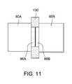
特定の実施態様では、2つの一次画素80を分離する隔壁セグメント130の下に2つ以上の基準検出器画素86を設けることができる。例えば、図11を参照すると、2つの並んだ基準検出器画素86Aおよび86Bは、散乱防止コリメータの同じ隔壁セグメント130の下に位置し、一方の基準検出器画素86Aは、第1の一次画素80Aに近接して位置決めされ、他方の基準検出器画素86Bは、第2の一次画素80Bに近接して位置決めされる。理解され得るように、実施態様の観点から、基準検出器画素86Aおよび86Bは、物理的に別々かつ別個の構造として、または別々かつ別個の回路を使用して電気的に管理される単一の画素構造の異なる部分などにより、基準画素動作(例えば、読み出しおよびリセット)が効果的かつ電気的に分離される共通もしくは単一の構造として提供され得る。 In certain implementations, there may be more than one
理解されるように、この配置では、基準検出器画素86Aによって生成される信号は、主に、第1の一次画素80Aとの電荷共有事象に起因し、基準検出器画素86Bによって生成される信号は、主に、第2の一次画素80Bとの電荷共有事象に起因する。したがって、一次画素80Aが事象によってトリガされると、基準検出器画素86Aからの信号は、電荷共有のために同じ事象によってトリガされ得る。それにより、そのような場合、基準検出器画素86Aからの信号は、読み出し前に一次画素80Aに追加される。同じプロセスが、一次画素80Bおよび基準検出器画素86Bについても成り立つ。 As will be appreciated, in this arrangement the signal produced by
理解されるように、図11の例は簡単にするために1D散乱防止グリッドコリメータの場面で示されているが、同じ原理は2D散乱防止グリッドの場面にも適用することができる。これらの場面では、各一次画素について、直接隣接する基準検出器画素からの信号が電荷共有補正に使用される。例えば、図12の2D散乱防止コリメータの例では、基準検出器画素86Aおよび86Bからの信号は、電荷共有事象での読み出しの前に一次画素80Aに追加され得る。同様に、基準検出器画素86Cおよび86Dからの信号は、電荷共有事象などでの読み出しの前に一次画素80Bに追加され得る。 As will be appreciated, although the example of FIG. 11 is shown in a 1D anti-scatter grid collimator context for simplicity, the same principles can be applied to a 2D anti-scatter grid context. In these scenarios, for each primary pixel, the signal from the immediately adjacent reference detector pixel is used for charge sharing correction. For example, in the 2D anti-scatter collimator example of FIG. 12, signals from
前述を念頭に置いて、図13を参照すると、基準検出器画素140を2D散乱防止コリメータ18の隔壁交差部142の下に設けることもできる。理解されるように、そのような基準検出器画素140は、4つの一次画素に実際には近接または隣接しており、したがってそれらの信号はそれに応じて使用することができる。さらに、異なって位置決めされた基準検出器画素(すなわち、隔壁セグメントの下の基準画素86および隔壁交差部の下の基準画素140)の使用は、異なる補正動作の実行を可能にし得る。 With the foregoing in mind and referring to FIG. 13,
例として、一実施態様では、隔壁セグメントの下の基準検出器画素86から取得された信号は、本明細書で説明するように、電荷共有補正に使用され得る。そのような手法において、隔壁交差部の下の基準検出器画素140は、やはり本明細書で説明するように、焦点整列補正のために使用され得る。このようにして、電荷共有補正と焦点整列補正の両方を同時に実行することができる。信号を電荷共有事象から区別し、かつ信号を焦点の不整列から区別するために、信号のエネルギー情報を使用することができる。典型的には、電荷共有事象により、基準検出器で低エネルギーの信号が発生する。一方、一次信号が焦点の不整列から基準検出器に達する場合、信号はより高いエネルギーを有し、そのような信号を電荷共有信号から弁別するための基礎として使用することができる。 By way of example, in one implementation, the signal obtained from the
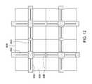
加えて、前述の例は、活性画素80のグループまたはアレイ(例えば、2×1、2×2、4×4アレイまたは他の構成)の周りに位置決めされた隔壁82(およびそれにより基準画素86)を示しているが、他の実施態様では、図14および図15に示すように、各活性画素80を隔壁82で取り囲むことができることを理解されたい。図14および図15に示す例では、散乱防止コリメータ18は、グリッドの各セルが500μm×500μmの検出器画素などの単一の活性画素を包含する2Dコリメータである。図14は、各活性画素80がすべての面で隔壁82によって囲まれ、したがってすべての面に基準画素86を有する例を示す。同様に、図15は、活性画素80に隣接する各隔壁82の下方の単一の基準画素86の代わりに、各活性画素80が当該活性画素80のみに関連付けられた基準画素86によって囲まれるように、並んだ基準画素86の対が代わりに提供され得る対応する例を示す。 In addition, the foregoing example illustrates partition walls 82 (and thereby reference pixels 86) positioned around groups or arrays (eg, 2×1, 2×2, 4×4 arrays or other configurations) of
本発明の技術的効果は、室温半導体検出器システム(例えば、直接変換検出器)と共に使用するためなど、基準検出器として散乱防止コリメータの隔壁の下に位置決めされた検出器素子(すなわち、基準検出器画素)の使用を含む。基準検出器画素が散乱防止コリメータの下にあるので、そこに入射する一次信号は、通常の動作ではブロックされる。したがって、基準検出器画素によって検出される信号は、典型的には、X線焦点が適切に整列されていると仮定して、電荷共有事象から発生する。この場面では、基準検出器画素によって生成された信号を使用して、隣り合う一次画素からの電荷共有事象を補正することができる。 A technical effect of the present invention is the use of a detector element (i.e., reference detection) positioned under the septum of an anti-scatter collimator as a reference detector, such as for use with room temperature semiconductor detector systems (e.g., direct conversion detectors). including the use of Since the reference detector pixel is below the anti-scatter collimator, primary signals incident thereon are blocked in normal operation. Thus, the signal detected by the reference detector pixel typically arises from charge sharing events, assuming the x-ray foci are properly aligned. In this scenario, the signal produced by the reference detector pixel can be used to correct for charge sharing events from neighboring primary pixels.
加えて、基準検出器画素からの信号は、X線焦点と検出器との間の相対運動に敏感である。この関係は、コリメータとX線源の相対位置を較正するために、または基準検出器からの信号の直接フィードバックに基づいてリアルタイムで焦点の位置を調整するために使用することができる。これらの態様は、直接変換検出器システムから忠実度の高い信号を得るために重要であり、それにより画像品質を向上させる。 Additionally, the signal from the reference detector pixel is sensitive to relative motion between the x-ray focus and the detector. This relationship can be used to calibrate the relative position of the collimator and x-ray source, or to adjust the position of the focal spot in real time based on direct feedback of the signal from the reference detector. These aspects are important for obtaining high fidelity signals from direct conversion detector systems, thereby improving image quality.
本明細書は、最良の様式を含む本発明を開示するため、およびどのような当業者も、任意のデバイスまたはシステムの作製および使用ならびに任意の組み込まれた方法の実行を含む本発明の実践を可能にするために、実施例を使用している。本発明の特許可能な範囲は、特許請求の範囲によって定義され、当業者が想到する他の実施例を含むことができる。そのような他の実施例は、特許請求の範囲の文言と異ならない構造要素を有する場合、または特許請求の範囲の文言と実質的な差のない等価の構造要素を含む場合、特許請求の範囲内にあることが意図されている。 This written description is intended to disclose the invention, including the best mode, and to enable any person skilled in the art to practice the invention, including making and using any device or system, and performing any incorporated method. An example is used to enable this. The patentable scope of the invention is defined by the claims, and may include other examples that occur to those skilled in the art. If such other embodiments have structural elements that do not differ from the language of the claims, or if they contain equivalent structural elements that do not materially differ from the language of the claims, intended to be within
10 CT撮像システム
12 X線源
18 散乱防止コリメータ
20 X線ビーム、X線光子
22 ビーム整形器、フィルタアセンブリ
24 患者、物体、被検体
26 減衰されたX線光子
28 検出器、検出器アレイ
30 システムコントローラ
32 直線位置決めサブシステム
34 回転サブシステム
36 モータコントローラ
38 X線コントローラ
40 データ取得システム(DAS)
42 コンピュータ
44 画像処理回路
46 非一時的メモリデバイス、メモリ
48 オペレータワークステーション
50 ディスプレイ
52 プリンタ
54 画像保管通信システム(PACS)
56 遠隔システム、クライアント
80 一次画素、活性画素
80A 第1の一次画素
80B 第2の一次画素
80C 一次画素
80D 一次画素
82 散乱防止コリメータ隔壁
86 基準検出器画素
86A 第1の基準画素、基準検出器画素
86B 第2の基準画素、基準検出器画素
86C 基準検出器画素
86D 基準検出器画素
86E 基準検出器画素
86F 基準検出器画素
86G 基準検出器画素
86H 基準検出器画素
90 焦点
90A 焦点
90B 焦点
100 ブロック
102 決定ブロック
104 ブロック
106 ブロック
108 較正係数
110 ブロック
112 焦点場所調整
120 電子雲
130 隔壁セグメント
140 基準検出器画素
142 隔壁交差部
X 次元
Y 次元
Z 次元10
42
56 remote system,
Claims (20)
Translated fromJapanese前記散乱防止コリメータ(18)の前記隔壁(82)の下方にならないように位置決めされた一次画素(80、80A、80B、80C、80D)のアレイ、および
1つまたは複数のそれぞれの一次画素(80、80A、80B、80C、80D)に隣接し、それぞれの隔壁(82)または隔壁(82)の交差部(142)の下方に位置決めされた少なくとも1つの基準画素(86、86A、86B、86C、86D、86E、86F、86G、86H、140)
を備える放射線検出器パネルと
を備え、
前記基準画素が、X線焦点の動きの検出もしくは補正、又は電荷共有事象補正に使用される信号を出力し、
前記少なくとも1つの基準画素(86、86A、86B、86C、86D、86E、86F、86G、86H、140)が、それぞれの一次画素(80、80A、80B、80C、80D)よりも面積が小さい、放射線検出器アセンブリ。an anti-scatter collimator (18) comprising x-ray attenuating partitions (82) arranged in a one-dimensional or two-dimensional geometry;
an array of primary pixels (80, 80A, 80B, 80C, 80D) positioned so as not to be below said septum (82) of said anti-scatter collimator (18); and one or more respective primary pixels (80 , 80A, 80B, 80C, 80D) and positioned below the respective septum (82) or the intersection (142) of the septum (82). 86D, 86E, 86F, 86G, 86H, 140)
a radiation detector panelcomprising
said reference pixel outputs a signal used for detection or correction of x-ray focal spot motion or charge sharing event correction;
wherein said at least one reference pixel (86, 86A, 86B, 86C, 86D, 86E, 86F, 86G, 86H, 140) has a smaller area than each primary pixel (80, 80A, 80B, 80C, 80D); Radiation detector assembly.
少なくとも1つの基準画素(86、86A、86B、86C、86D、86E、86F、86G、86H、140)から信号を読み出すことであって、前記少なくとも1つの基準画素(86、86A、86B、86C、86D、86E、86F、86G、86H、140)が、検出器パネルに近接して位置決めされた散乱防止コリメータ(18)のX線減衰隔壁(82)または隔壁交差部(142)の下方に位置決めされている、少なくとも1つの基準画素(86、86A、86B、86C、86D、86E、86F、86G、86H、140)から信号を読み出すことと、
前記少なくとも1つの基準画素からの信号を分析して電荷共有事象またはX線焦点(90、90A、90B)の不整列の一方または両方を示すことと、
前記分析に基づいて、前記電荷共有事象またはX線焦点(90、90A、90B)の不整列の一方または両方の補正を実行することと
を含み、
前記少なくとも1つの基準画素(86、86A、86B、86C、86D、86E、86F、86G、86H、140)が、それぞれの一次画素(80、80A、80B、80C、80D)よりも面積が小さい、方法。A method for X-ray signal correction, comprising:
reading a signal fromat least one reference pixel (86, 86A, 86B, 86C, 86D, 86E, 86F, 86G, 86H, 140), saidat least one reference pixel (86, 86A, 86B, 86C, 86D, 86E, 86F, 86G, 86H, 140) below the x-ray attenuation septum (82) or septum intersection (142) of the anti-scatter collimator (18) positioned closeto the detector panel. reading a signal fromatleast one positioned reference pixel (86, 86A, 86B, 86C, 86D, 86E, 86F, 86G, 86H, 140) ;
analyzingthe signal from the at least one reference pixel to indicate one or both of a charge sharing event or misalignment of the x-ray focus (90, 90A, 90B);
performing corrections for one or both of the charge-sharing events or the misalignment of the X-ray foci (90,90A , 90B) based on the analysis;
wherein said at least one reference pixel (86, 86A, 86B, 86C, 86D, 86E, 86F, 86G, 86H, 140) has a smaller area than each primary pixel (80, 80A, 80B, 80C, 80D); Method.
信号パターンが検出されない場合、補正措置を取らないことと、
信号パターンが検出される場合、前記信号パターンに基づいてX線焦点(90、90A、90B)の位置を推定することと
をさらに含む、請求項8に記載の方法。analyzing the signal comprises analyzing the signal for a signal pattern indicative of misalignment of X-ray foci (90, 90A, 90B);
taking no corrective action if no signal pattern is detected;
9. The method of claim 8, further comprising estimating the position of the X-ray focal point (90, 90A, 90B) based on the signal pattern if a signal pattern is detected.
前記X線焦点(90、90A、90B)の不整列を補正する較正係数(108)を生成することと、
前記較正係数(108)を使用して、後続の読み出し動作で前記検出器パネルの複数の一次画素(80、80A、80B、80C、80D)から読み出されたデータを調整してX線焦点(90、90A、90B)の不整列を補償することであって、前記後続の読み出し動作は、物体または患者(24)のスキャンであることと、
前記較正係数(108)を使用して、リアルタイムで焦点(90、90A、90B)の前記位置を調整して前記不整列を補正することと
をさらに含む、請求項8に記載の方法。reading out theat least one reference pixel (86, 86A, 86B, 86C, 86D, 86E, 86F, 86G, 86H, 140) is performed during air scanning;
generating a calibration factor (108) that corrects for misalignment of the x-ray focus (90, 90A, 90B);
Said calibration factor (108) is used to adjust the data read out from a plurality of primary pixels (80, 80A, 80B, 80C, 80D) of said detector panel in subsequent readout operations to provide an x-ray focus ( 90, 90A, 90B), wherein said subsequent readout operation is a scan of the object or patient (24);
9. The method of claim 8, further comprising: using the calibration factor (108) to adjust the position of the focus (90, 90A, 90B) in real time to compensate for the misalignment.
画像再構築中に焦点(90、90A、90B)の不整列の前記調整を使用することと
をさらに含む、請求項8に記載の方法。calculating adjustments for misalignment of the x-ray focus (90, 90A, 90B) observed during the scan;
9. The method of claim 8, further comprising: using said adjustment of focus (90, 90A, 90B) misalignment during image reconstruction.
1つまたは複数のそれぞれの電荷共有信号を生成し、前記電荷共有事象が検出された前記それぞれの基準画素(86、86A、86B、86C、86D、86E、86F、86G、86H、140)に隣接する1つまたは複数のそれぞれの一次画素(80、80A、80B、80C、80D)の前記電荷共有事象を補正すること
をさらに含む、請求項8に記載の方法。analyzing the signal comprises analyzing the signal for charge sharing events;
generating one or more respective charge sharing signals adjacent said respective reference pixel (86, 86A, 86B, 86C, 86D, 86E, 86F, 86G, 86H, 140) where said charge sharing event was detected; 9. The method of claim 8, further comprising: compensating for the charge sharing events of one or more respective primary pixels (80, 80A, 80B, 80C, 80D).
X線減衰隔壁(82)を備える散乱防止コリメータ(18)、および
前記散乱防止コリメータ(18)の前記隔壁(82)の下方にならないように位置決めされた一次画素(80、80A、80B、80C、80D)のアレイと、
それぞれの隔壁(82)または隔壁(82)の交差部(142)の下方に位置決めされた少なくとも1つの基準画素(86、86A、86B、86C、86D、86E、86F、86G、86H、140)と
を備える放射線検出器パネル
を備える、放射線検出器アセンブリと、
電荷共有事象が発生したとき、前記少なくとも1つの基準画素(86、86A、86B、86C、86D、86E、86F、86G、86H、140)およびそれぞれの一次画素(80、80A、80B、80C、80D)からの信号を組み合わせるように構成された読み出し電子回路と
を備え、
前記基準画素が電荷共有事象補正に使用される信号を出力し、
少なくとも1つの前記基準画素(86、86A、86B、86C、86D、86E、86F、86G、86H、140)が、それぞれの一次画素(80、80A、80B、80C、80D)よりも面積が小さい、撮像システム(10)。an x-ray source (12) configured during operation to emit x-ray photons (20) from a focal point (90, 90A, 90B);
an anti-scatter collimator (18) comprising an x-ray attenuating septum (82); and primary pixels (80, 80A, 80B, 80C, 80, 80A, 80B, 80C, 80D) array;
at least one reference pixel (86, 86A, 86B, 86C, 86D, 86E, 86F, 86G, 86H, 140) positioned below each septum (82) or intersection (142) of the septum (82); a radiation detector assembly comprising a radiation detector panel comprising and
When a charge sharing event occurs, theat least one reference pixel (86, 86A, 86B, 86C, 86D, 86E, 86F, 86G, 86H, 140) and each primary pixel (80, 80A, 80B, 80C, readout electronics configured to combine signals from 80D);
the reference pixel outputs a signal used for charge sharing event correction;
at least one of said reference pixels (86, 86A, 86B, 86C, 86D, 86E, 86F, 86G, 86H, 140) is smaller in area than each primary pixel (80, 80A, 80B, 80C, 80D); An imaging system (10).
前記焦点(90、90A、90B)の不整列を補正する較正係数(108)を生成し、
前記較正係数(108)を使用して、後続の読み出し動作で前記一次画素(80、80A、80B、80C、80D)のアレイから読み出されたデータを調整して焦点(90、90A、90B)の不整列を補償し、
画像再構築中に前記データ調整された焦点(90、90A、90B)の不整列を使用する
ようにさらに構成される、請求項17に記載の撮像システム(10)。the processing component comprising:
generating a calibration factor (108) that corrects for misalignment of said focus (90, 90A, 90B);
The calibration factor (108) is used to adjust the data read out from the array of primary pixels (80, 80A, 80B, 80C, 80D) in subsequent readout operations to focus (90, 90A, 90B). compensates for the misalignment of
18. The imaging system (10) of claim 17, further configured to: use the data adjusted focus (90, 90A, 90B) misalignment during image reconstruction.
スキャン中に観察されるX線焦点(90、90A、90B)の不整列の調整を計算し、
フィードバックを提供してリアルタイムで前記焦点(90、90A、90B)の前記位置を調整する
ようにさらに構成される、請求項17に記載の撮像システム(10)。the processing component comprising:
calculating adjustments for misalignment of the X-ray foci (90, 90A, 90B) observed during the scan;
18. The imaging system (10) of claim 17, further configured to provide feedback to adjust the position of the focus (90, 90A, 90B) in real time.
スキャン中に観察される焦点(90、90A、90B)の不整列の調整係数を計算し、
画像再構築中に前記調整係数を使用する
ようにさらに構成される、請求項17に記載の撮像システム(10)。the processing component comprising:
calculating an adjustment factor for the misalignment of focus (90, 90A, 90B) observed during the scan;
18. The imaging system (10) of claim 17, further configured to use said adjustment factor during image reconstruction.
Applications Claiming Priority (3)
| Application Number | Priority Date | Filing Date | Title |
|---|---|---|---|
| US15/589,412 | 2017-05-08 | ||
| US15/589,412US10779778B2 (en) | 2017-05-08 | 2017-05-08 | Reference detector elements in conjunction with an anti-scatter collimator |
| PCT/US2018/031308WO2018208642A1 (en) | 2017-05-08 | 2018-05-07 | Reference detector elements in conjunction with an anti-scatter collimator |
Publications (2)
| Publication Number | Publication Date |
|---|---|
| JP2020519872A JP2020519872A (en) | 2020-07-02 |
| JP7146811B2true JP7146811B2 (en) | 2022-10-04 |
Family
ID=62244570
Family Applications (1)
| Application Number | Title | Priority Date | Filing Date |
|---|---|---|---|
| JP2019561303AActiveJP7146811B2 (en) | 2017-05-08 | 2018-05-07 | Reference detector element combined with anti-scatter collimator |
Country Status (5)
| Country | Link |
|---|---|
| US (1) | US10779778B2 (en) |
| EP (1) | EP3634234A1 (en) |
| JP (1) | JP7146811B2 (en) |
| CN (1) | CN110891489B (en) |
| WO (1) | WO2018208642A1 (en) |
Families Citing this family (11)
| Publication number | Priority date | Publication date | Assignee | Title |
|---|---|---|---|---|
| US10610191B2 (en)* | 2017-07-06 | 2020-04-07 | Prismatic Sensors Ab | Managing geometric misalignment in x-ray imaging systems |
| EP3444826A1 (en)* | 2017-08-14 | 2019-02-20 | Koninklijke Philips N.V. | Low profile anti scatter and anti charge sharing grid for photon counting computed tomography |
| WO2019041223A1 (en)* | 2017-08-31 | 2019-03-07 | Shenzhen United Imaging Healthcare Co., Ltd. | Ct focal point determination method and system |
| CN107582089B (en)* | 2017-09-29 | 2021-06-29 | 上海联影医疗科技股份有限公司 | Collimator, imaging device, focus position tracking method and correction method |
| EP3508887A1 (en)* | 2018-01-09 | 2019-07-10 | Koninklijke Philips N.V. | Charge sharing calibration method and system |
| DE102018102998A1 (en)* | 2018-02-09 | 2019-08-14 | Infineon Technologies Ag | Apparatus, method and computer program for comparing the output of sensor cells |
| US10898159B2 (en)* | 2019-01-11 | 2021-01-26 | General Electric Company | X-ray imaging system use and calibration |
| US11141128B2 (en)* | 2019-12-13 | 2021-10-12 | General Electric Company | Systems and methods for focal spot motion detection and correction |
| US11779296B2 (en)* | 2020-03-20 | 2023-10-10 | Canon Medical Systems Corporation | Photon counting detector based edge reference detector design and calibration method for small pixelated photon counting CT apparatus |
| US11744531B2 (en)* | 2021-06-29 | 2023-09-05 | GE Precision Healthcare LLC | Systems and methods for focal spot motion detection in both x- and y-directions and correction |
| US20240358334A1 (en)* | 2023-04-26 | 2024-10-31 | GE Precision Healthcare LLC | Method and system for focal spot tracking and reducing scatter cross talk in medical imaging |
Citations (4)
| Publication number | Priority date | Publication date | Assignee | Title |
|---|---|---|---|---|
| JP2010213902A (en) | 2009-03-17 | 2010-09-30 | Shimadzu Corp | Radiographic apparatus |
| JP2011106887A (en) | 2009-11-13 | 2011-06-02 | Hitachi Ltd | Radiographic imaging apparatus and nuclear medical diagnostic apparatus using the same |
| US20170016998A1 (en) | 2015-05-28 | 2017-01-19 | General Electric Company | Systems and methods for sub-pixel location determination |
| WO2017122514A1 (en) | 2016-01-12 | 2017-07-20 | 株式会社日立製作所 | Radiation imaging apparatus |
Family Cites Families (21)
| Publication number | Priority date | Publication date | Assignee | Title |
|---|---|---|---|---|
| US4982096A (en)* | 1988-01-06 | 1991-01-01 | Hitachi Medical Corporation | Multi-element radiation detector |
| US6100531A (en)* | 1998-04-17 | 2000-08-08 | Adac Laboratories | Dual-purpose radiation transmission source for nuclear medicine imaging system |
| US6583420B1 (en) | 2000-06-07 | 2003-06-24 | Robert S. Nelson | Device and system for improved imaging in nuclear medicine and mammography |
| WO2005006986A1 (en) | 2003-07-22 | 2005-01-27 | Koninklijke Philips Electronics N.V. | Radiation mask for two dimensional ct detector |
| WO2005102170A1 (en)* | 2004-04-21 | 2005-11-03 | Philips Intellectual Property & Standards Gmbh | Cone-beam coherent-scatter computer tomograph |
| JP2008506945A (en)* | 2004-07-14 | 2008-03-06 | オーボテック メディカル ソリューションズ リミティド | Radiation detector head |
| US7606347B2 (en) | 2004-09-13 | 2009-10-20 | General Electric Company | Photon counting x-ray detector with overrange logic control |
| JP3928647B2 (en)* | 2004-09-24 | 2007-06-13 | 株式会社日立製作所 | Radiation imaging apparatus and nuclear medicine diagnostic apparatus using the same |
| US7101078B1 (en)* | 2005-02-11 | 2006-09-05 | General Electric Company | Methods and systems for imaging system radiation source alignment |
| US20060284097A1 (en)* | 2005-06-16 | 2006-12-21 | Wang Sharon X | Simultaneous scanning by computed tomography (CT) and single photon emission computed tomography (SPECT) with automatic patient motion correction |
| US7450683B2 (en) | 2006-09-07 | 2008-11-11 | General Electric Company | Tileable multi-layer detector |
| US7486764B2 (en) | 2007-01-23 | 2009-02-03 | General Electric Company | Method and apparatus to reduce charge sharing in pixellated energy discriminating detectors |
| EP2276408B1 (en)* | 2008-05-08 | 2019-07-10 | Arineta Ltd. | X ray imaging system with scatter radiation correction and method of using same |
| DE102010020610A1 (en)* | 2010-05-14 | 2011-11-17 | Siemens Aktiengesellschaft | Radiation detector and method for producing a radiation detector |
| US8315352B2 (en)* | 2010-09-16 | 2012-11-20 | General Electric Company | System and method of spectral calibration and basis material decomposition for X-ray CT systems |
| US9135728B2 (en)* | 2012-04-04 | 2015-09-15 | General Electric Company | System and method for multi-energy computed tomography imaging |
| US9510792B2 (en) | 2013-05-17 | 2016-12-06 | Toshiba Medical Systems Corporation | Apparatus and method for collimating X-rays in spectral computer tomography imaging |
| US9002084B2 (en)* | 2013-08-30 | 2015-04-07 | Ge Medical Systems Israel, Ltd | Systems and methods for summing signals from an imaging detector |
| US9204852B2 (en)* | 2013-12-31 | 2015-12-08 | General Electric Company | Systems and methods for increased energy separation in multi-energy X-ray imaging |
| US9219178B2 (en) | 2014-03-21 | 2015-12-22 | Kabushiki Kaisha Toshiba | Method to fabricate collimator structures on a direct conversion semiconductor X-ray detector |
| US10222489B2 (en)* | 2017-03-13 | 2019-03-05 | General Electric Company | Pixel-design for use in a radiation detector |
- 2017
- 2017-05-08USUS15/589,412patent/US10779778B2/enactiveActive
- 2018
- 2018-05-07CNCN201880029775.8Apatent/CN110891489B/enactiveActive
- 2018-05-07JPJP2019561303Apatent/JP7146811B2/enactiveActive
- 2018-05-07WOPCT/US2018/031308patent/WO2018208642A1/ennot_activeCeased
- 2018-05-07EPEP18727118.4Apatent/EP3634234A1/enactivePending
Patent Citations (4)
| Publication number | Priority date | Publication date | Assignee | Title |
|---|---|---|---|---|
| JP2010213902A (en) | 2009-03-17 | 2010-09-30 | Shimadzu Corp | Radiographic apparatus |
| JP2011106887A (en) | 2009-11-13 | 2011-06-02 | Hitachi Ltd | Radiographic imaging apparatus and nuclear medical diagnostic apparatus using the same |
| US20170016998A1 (en) | 2015-05-28 | 2017-01-19 | General Electric Company | Systems and methods for sub-pixel location determination |
| WO2017122514A1 (en) | 2016-01-12 | 2017-07-20 | 株式会社日立製作所 | Radiation imaging apparatus |
Also Published As
| Publication number | Publication date |
|---|---|
| US20180317869A1 (en) | 2018-11-08 |
| CN110891489A (en) | 2020-03-17 |
| WO2018208642A1 (en) | 2018-11-15 |
| JP2020519872A (en) | 2020-07-02 |
| EP3634234A1 (en) | 2020-04-15 |
| CN110891489B (en) | 2023-09-01 |
| US10779778B2 (en) | 2020-09-22 |
Similar Documents
| Publication | Publication Date | Title |
|---|---|---|
| JP7146811B2 (en) | Reference detector element combined with anti-scatter collimator | |
| CN111435120B (en) | Use and calibration of an X-ray imaging system | |
| JP7053650B2 (en) | Pixel design for use in radiation detectors | |
| JP7175922B2 (en) | Scatter correction techniques for use in radiation detectors | |
| US8262288B2 (en) | Focal spot position determiner | |
| CN102793556B (en) | Method and computed tomography system for generating tomographic image datasets | |
| JP6517376B2 (en) | X-ray device with reduced pile-up | |
| CN112971816B (en) | System and method for focus motion detection and correction | |
| WO2017170408A1 (en) | X-ray detection system, x-ray device, and device and method for processing x-ray detection data | |
| JP2022013686A (en) | X-ray CT equipment, data processing method and program | |
| JP2004208884A (en) | X-ray data collector and x-ray ct apparatus | |
| JP7387814B2 (en) | System and method for detection and correction of focal spot motion in both the X and Y directions | |
| JP2024010658A (en) | Photon counting detector device, overlap micropixel addition method, program and photon counting CT device | |
| US10119924B2 (en) | Computed tomography with detector wobble | |
| JP2022013679A (en) | Medical image processing method, medical image processing device and X-ray CT device | |
| JP2021013489A (en) | X-ray CT system and medical processing equipment | |
| JP4430987B2 (en) | Radiation tomography apparatus, tomography method thereof, and correction data calculation method | |
| JP2023012246A (en) | MEDICAL IMAGE PROCESSING APPARATUS, X-RAY CT APPARATUS, MEDICAL IMAGE PROCESSING METHOD AND PROGRAM | |
| JP2024036754A (en) | X-ray CT device, data processing method and data processing program | |
| JP2022158914A (en) | Calibration method and X-ray scanner system | |
| JPH1133019A (en) | Radiation exposure and detection device and tomograph |
Legal Events
| Date | Code | Title | Description |
|---|---|---|---|
| A621 | Written request for application examination | Free format text:JAPANESE INTERMEDIATE CODE: A621 Effective date:20201218 | |
| RD02 | Notification of acceptance of power of attorney | Free format text:JAPANESE INTERMEDIATE CODE: A7422 Effective date:20210520 | |
| RD04 | Notification of resignation of power of attorney | Free format text:JAPANESE INTERMEDIATE CODE: A7424 Effective date:20210524 | |
| A977 | Report on retrieval | Free format text:JAPANESE INTERMEDIATE CODE: A971007 Effective date:20211130 | |
| A131 | Notification of reasons for refusal | Free format text:JAPANESE INTERMEDIATE CODE: A131 Effective date:20220105 | |
| A521 | Request for written amendment filed | Free format text:JAPANESE INTERMEDIATE CODE: A523 Effective date:20220404 | |
| TRDD | Decision of grant or rejection written | ||
| A01 | Written decision to grant a patent or to grant a registration (utility model) | Free format text:JAPANESE INTERMEDIATE CODE: A01 Effective date:20220824 | |
| A61 | First payment of annual fees (during grant procedure) | Free format text:JAPANESE INTERMEDIATE CODE: A61 Effective date:20220921 | |
| R150 | Certificate of patent or registration of utility model | Ref document number:7146811 Country of ref document:JP Free format text:JAPANESE INTERMEDIATE CODE: R150 | |
| S111 | Request for change of ownership or part of ownership | Free format text:JAPANESE INTERMEDIATE CODE: R313113 | |
| R350 | Written notification of registration of transfer | Free format text:JAPANESE INTERMEDIATE CODE: R350 |