JP7146516B2 - Driving evaluation device and in-vehicle device - Google Patents
Driving evaluation device and in-vehicle deviceDownload PDFInfo
- Publication number
- JP7146516B2 JP7146516B2JP2018148830AJP2018148830AJP7146516B2JP 7146516 B2JP7146516 B2JP 7146516B2JP 2018148830 AJP2018148830 AJP 2018148830AJP 2018148830 AJP2018148830 AJP 2018148830AJP 7146516 B2JP7146516 B2JP 7146516B2
- Authority
- JP
- Japan
- Prior art keywords
- vehicle
- driving
- information
- inter
- driving evaluation
- Prior art date
- Legal status (The legal status is an assumption and is not a legal conclusion. Google has not performed a legal analysis and makes no representation as to the accuracy of the status listed.)
- Active
Links
Images


Landscapes
- Control Of Driving Devices And Active Controlling Of Vehicle (AREA)
- Time Recorders, Dirve Recorders, Access Control (AREA)
- Traffic Control Systems (AREA)
Description
Translated fromJapanese 本発明は、運転評価装置および車載器に関し、特に例えば煽り運転のような危険な運転を評価するための技術に関する。 BACKGROUND OF THE
近年、自動車における煽り運転のような危険な運転行為が社会問題になっている。したがって、一般的な運転者や商用車を運転する乗務員などに対して、煽り運転などの行為をしないように指導や教育を行うことが望まれる。 BACKGROUND ART In recent years, dangerous driving behaviors such as driving while driving a car have become a social problem. Therefore, it is desirable to provide guidance and education to general drivers and crew members who drive commercial vehicles so that they do not engage in acts such as reckless driving.
例えば、ドライブレコーダやデジタルタコグラフのような、トラックなどの車両に搭載される車載器は、近年では様々な機能を搭載しているが、煽り運転のような危険な運転行為自体を検出する機能は備えていない。 For example, in-vehicle devices such as drive recorders and digital tachographs installed in vehicles such as trucks are equipped with various functions in recent years. not prepared.
また、車両の運行を管理する企業等においては、各車両の車載器が記録した運行情報を事務所PCで解析して各乗務員の安全運転指導に役立てているが、データ解析により煽り運転のような危険な運転行為を検出することは非常に難しい。 In addition, in companies that manage vehicle operation, the operation information recorded by the on-board equipment of each vehicle is analyzed on the office PC and used for safe driving guidance for each crew member. Detecting dangerous driving behavior is very difficult.
例えば、特許文献1の運転支援装置は、煽り行為を検出して後続車両との事故やトラブルを防止するための技術を示している。具体的には、周辺状況判定部がナビゲーション装置、道路情報収集装置、カメラの出力から周辺の状況を判定し、自車両状態判定部が速度センサ、加速度センサ、カメラ、灯火系および車両制御系の出力から自車両の状態を判定し、他車両状態判定部がカメラ、車両間通信装置、レーダの出力から他車両の状態を判定する。煽り危険度判定部は、周辺状況、自車両状態、他車両状態から煽り危険度を算出し、算出結果に基づいて通知制御や動作制御を実行する。 For example, the driving support device of
また、特許文献2には、車両管理者が速やかにドライバーの運転状況を把握することのできる蛇行運転通報システムが開示されている。具体的には、車載カメラの画像情報を解析して車両と自車線の位置関係を検知し、車両が車線を逸脱した際にドライバーに車線逸脱警報を発する車線逸脱検知装置と、サーバと無線通信可能な車載器とを備え、車載器は、車線逸脱検知装置の車線逸脱警報作動に関する情報を受け取り、サーバに車線逸脱情報を送信する。 Further, Patent Literature 2 discloses a meandering driving notification system that enables a vehicle manager to quickly grasp the driving situation of a driver. Specifically, a lane departure detection device that analyzes image information from an in-vehicle camera to detect the positional relationship between the vehicle and its own lane and issues a lane departure warning to the driver when the vehicle deviates from the lane, and wireless communication with the server. The vehicle-mounted device receives information regarding the lane departure warning activation of the lane departure detection device and transmits the lane departure information to the server.
特許文献3の運転特徴判定システムは、車輌に搭載したカメラが撮像した周辺の画像に基づいて、精度よく運転者の運転の特徴を判定するようになっている。すなわち、車載カメラが撮像した周辺の画像に基づいて、車輌に対するユーザの運転の特徴を判定する。車載通信装置は、車載カメラ、車速センサ、加速度センサ及びGPS受信機等から得られる情報を運転特徴判定装置へ送信する。運転特徴判定装置は、車載通信装置から受信した車載カメラの撮像画像に基づいて車輌の挙動を検出し、車輌が所定挙動を行ったか否かを運転特徴として判定する。運転特徴判定装置は、車載カメラの撮像画像に基づいて、例えば車線変更禁止判定、車線変更頻度判定、白線跨ぎ判定、赤信号進入判定、停車距離判定及び急ブレーキ判定等を行う。 The driving feature determination system of Patent Document 3 accurately determines driving features of the driver based on images of the surroundings captured by a camera mounted on the vehicle. That is, the user's driving characteristics of the vehicle are determined based on the image of the surroundings captured by the vehicle-mounted camera. The in-vehicle communication device transmits information obtained from the in-vehicle camera, vehicle speed sensor, acceleration sensor, GPS receiver, etc. to the driving characteristic determination device. The driving feature determination device detects the behavior of the vehicle based on the captured image of the vehicle-mounted camera received from the vehicle-mounted communication device, and determines whether or not the vehicle behaves as a driving feature. The driving feature determination device performs, for example, lane change prohibition determination, lane change frequency determination, white line crossing determination, red light approach determination, stopping distance determination, and sudden braking determination, etc., based on the image captured by the vehicle-mounted camera.
特許文献4には、十分な警告効果が得られて、適切な運転支援を行うことができる情報提供装置、情報提供方法及び情報提供システムが開示されている。具体的には、車両の進行方向の外側を撮影し、撮影して得られた映像情報を基に車両の車線逸脱を判定し、逸脱している場合、過去X1秒間の車線逸脱検出回数Y1を算出し、算出した車線逸脱検出回数Y1が所定の閾値未満であれば、車線逸脱に対する警告を行い、算出した車線逸脱検出回数Y1が所定の閾値以上であれば、休憩を促す警告を行う。 Patent Literature 4 discloses an information providing device, an information providing method, and an information providing system capable of obtaining a sufficient warning effect and performing appropriate driving assistance. Specifically, the outside of the direction of travel of the vehicle is photographed, and based on the image information obtained by photographing, the lane deviation of the vehicle is determined. If the calculated lane departure detection count Y1 is less than a predetermined threshold value, a warning against lane departure is issued, and if the calculated lane departure detection count Y1 is equal to or greater than the predetermined threshold value, a warning prompting a break is issued.
例えば、特定車両とその前方を走行している他車両との間の車間距離を測定できる場合には、測定した車間距離の大きさに基づいて、煽り運転のような危険行為の可能性を、ある程度は予想できる。しかし、当該特定車両の運転者が意図的に車間距離を詰めたのか、それとも何らかの原因により自然に車間距離が小さくなったのかを区別することは困難である。 For example, if it is possible to measure the inter-vehicle distance between a specific vehicle and another vehicle traveling in front of it, the possibility of dangerous behavior, such as reckless driving, is determined based on the measured inter-vehicle distance. predictable to some extent. However, it is difficult to distinguish whether the driver of the specific vehicle intentionally shortened the inter-vehicle distance or whether the inter-vehicle distance naturally decreased for some reason.
また、実際の運転の状況は、運転者個人の癖などの影響により大きく変動する。したがって、例えば車間距離などの運行情報が異常か否かを区別するために、運行情報を事前に定めた閾値と比較するような場合には、運転者の単なる癖を意図的な危険な運転操作と誤認する可能性がある。 In addition, the actual driving situation greatly fluctuates due to the influence of the driver's personal habits and the like. Therefore, in the case of comparing the operation information with a predetermined threshold in order to distinguish whether the operation information such as the inter-vehicle distance is abnormal, for example, the mere habit of the driver can be regarded as an intentional dangerous driving operation. may be misidentified as
本発明は、上述した事情に鑑みてなされたものであり、その目的は、例えば煽り運転のような異常な運転行為を正しく検出し評価することが可能な運転評価装置および車載器を提供することにある。 SUMMARY OF THE INVENTION The present invention has been made in view of the circumstances described above, and an object of the present invention is to provide a driving evaluation device and an on-vehicle device capable of correctly detecting and evaluating abnormal driving behavior such as lean driving. It is in.
前述した目的を達成するために、本発明に係る運転評価装置および車載器は、下記(1)~(4)を特徴としている。
(1) 車両上で検出された、もしくは過去に記録された運行情報に基づいて、前記車両における危険運転の評価を実施する運転評価装置であって、
前記運行情報が、前記車両と当該車両の前方を走行している他車両との車間距離に応じて変化する第1の情報と、前記車両の走行レーンを区画する左右の線と前記車両との左右方向の相対的な位置関係に応じて変化する第2の情報とを含み、
前記第2の情報に基づいて統計量を算出し、前記第1の情報に基づいて前記車間距離が正常範囲より短くなったことを検知した場合に、前記第2の情報の統計量に基づいて危険運転が行われたか否かを判定する運転評価部、
を備え、
前記運転評価部は、前記第1の情報に基づいて前記車間距離が前記正常範囲にあることを検知している状態で、前記第2の情報に基づいて算出した統計量を学習値として取得し、前記学習値を前記危険運転の判定のための閾値に反映する、
ことを特徴とする運転評価装置。In order to achieve the above object, the driving evaluation device and the vehicle-mounted device according to the present invention are characterized by the following (1) to (4 ).
(1) A driving evaluation device that evaluates dangerous driving in a vehicle based on operation information detected on the vehicle or recorded in the past,
The operation information includes first information that changes according to the inter-vehicle distance between the vehicle and another vehicle running in front of the vehicle, and left and right lines that divide the driving lane of the vehicle and the vehicle. and second information that changes according to the relative positional relationship in the horizontal direction,
A statistic is calculated based on the second information, and when it is detected that the inter-vehicle distance is shorter than the normal range based on the first information, based on the statistic of the second information a driving evaluation unit that determines whether or not dangerous driving has been performed;
with
The driving evaluation unit acquires a statistic calculated based on the second information as a learning value while detecting that the inter-vehicle distance is within the normal range based on the first information. , reflecting the learned value in a threshold value for determining the dangerous driving;
A driving evaluation device characterized by:
(2) 前記運転評価部は、前記車間距離の大きさに、少なくとも前記車両の車速を反映して前記正常範囲を設定する、
ことを特徴とする上記(1)に記載の運転評価装置。(2 ) The driving evaluation unit sets the normal range for the inter-vehicle distance by reflecting at least the vehicle speed of the vehicle;
The driving evaluation device accordingto (1) above, characterized in that:
(3) 前記運転評価部は、前記車両におけるウインカー作動の有無を表す情報を、前記危険運転の判定に利用する、
ことを特徴とする上記(1)又は(2)に記載の運転評価装置。(3 ) The driving evaluation unit uses information indicating whether or not the blinker is activated in the vehicle to determine the dangerous driving.
The driving evaluation device according to the above (1)or (2) , characterized by:
(4) 上記(1)乃至(3)のいずれかに記載の運転評価装置を搭載した、ことを特徴とする車載器。(4 ) A vehicle-mounted device, characterized in that the driving evaluation device according to any one of the above (1) to (3 ) is installed.
上記(1)の構成の運転評価装置によれば、例えば煽り運転のような異常な運転行為を正しく検出し評価することが可能になる。すなわち、煽り運転の場合には、前を走行している他車両への異常接近と共に、左右に蛇行しながら運転するような傾向が一般的に見られる。そこで、第2の情報の統計量を監視することにより、蛇行運転のような異常な運転状況を検知する。そして、車間距離の異常接近を検知した状態で、同時に蛇行運転のような異常が検知された場合には、煽り運転のような異常な運転状況である可能性が非常に高い。 According to the driving evaluation device having the configuration (1) above, it is possible to correctly detect and evaluate an abnormal driving behavior such as, for example, lean driving. That is, in the case of leaning driving, it is generally seen that the vehicle tends to meander left and right while driving abnormally close to another vehicle running in front. Therefore, abnormal driving conditions such as meandering driving are detected by monitoring the statistics of the second information. Then, in a state in which an abnormal approaching distance between the vehicles is detected, if an abnormality such as meandering driving is detected at the same time, it is very likely that the vehicle is in an abnormal driving situation such as rush driving.
更に、上記(1)の構成の運転評価装置によれば、煽り運転のような異常な運転行為を行っていない状態で取得した統計量の学習値を閾値に反映するので、煽り運転の有無を正しく判定することが可能になる。すなわち、運転中における車両の蛇行状況については運転者の個人差の影響が大きいので、事前に定めた閾値を用いて蛇行運転を判定すると、誤判定が生じやすい。そこで、蛇行運転をしていないときの統計量を学習することにより、個人差の影響を排除し、蛇行運転の正しい判定を行うことが容易になる。Furthermore, according to the driving evaluation device having the configuration (1 ) above, the learning value of the statistic acquired in a state in which no abnormal driving action such as swaying is performed is reflected in the threshold value, so the presence or absence of swaying driving can be determined. It is possible to judge correctly. That is, since the meandering state of the vehicle during driving is greatly affected by individual differences between drivers, erroneous determination is likely to occur if meandering driving is determined using a predetermined threshold value. Therefore, by learning the statistic when the vehicle is not meandering, the influence of individual differences can be eliminated, making it easier to correctly determine meandering driving.
上記(2)の構成の運転評価装置によれば、煽り運転のような異常な運転状況か否かを判定する精度を上げることができる。例えば、徐行運転しているような状況では車間距離が小さくなっても時間的に余裕があるので危険な状況は発生しにくく、煽り運転の可能性も低いと考えられる。一方、法定速度を超えるような高速で走行しながら車間距離が小さくなった場合には、衝突までの時間的な余裕がほとんどなく、危険性が高く、意図的な煽り運転の状況である可能性が高いと考えられる。According to the driving evaluation device having the configuration (2 ) above, it is possible to improve the accuracy of determining whether or not the vehicle is in an abnormal driving situation such as a rushing operation. For example, when driving slowly, even if the inter-vehicle distance is small, there is still time to spare, so dangerous situations are less likely to occur, and the possibility of rash driving is considered to be low. On the other hand, if the inter-vehicle distance becomes small while driving at a speed exceeding the legal speed limit, there is almost no time to wait for a collision, which is highly dangerous and may be a situation of intentional slamming. is considered to be high.
上記(3)の構成の運転評価装置によれば、煽り運転のような異常な運転状況か否かを判定する精度を上げることができる。例えば、前方を走行している他車両との車間距離が小さくなった状態で、ウインカー操作を行ったような場合には、単なる車線変更に起因して車両の左右方向の位置が大きく変動したのであり、煽り運転を行っている可能性が低いと考えられる。According to the driving evaluation device having the configuration (3 ) above, it is possible to improve the accuracy of determining whether or not the vehicle is in an abnormal driving situation such as a rushing operation. For example, if the turn signal is operated when the distance between the vehicle and another vehicle running ahead is small, the vehicle's position in the left and right direction will fluctuate greatly due to a mere lane change. Therefore, it is thought that there is a low possibility that the driver is driving under pressure.
上記(4)の構成の車載器によれば、車両の運行中に、煽り運転のような異常な運転状況をリアルタイムで検知し警報等を出力できる。これにより、自車両の運転者に対して危険な状況であることを認識させ、運転マナーを向上させることが可能になる。また、煽り運転などの異常な運転操作のデータを運行情報として記録する際に、記録すべきデータの量を減らすことができる。また、記録された運行データを事務所PC等を用いて評価する際に、データ処理や操作が容易になる。According to the vehicle-mounted device having the configuration (4 ) above, it is possible to detect an abnormal driving situation such as rush driving in real time and output an alarm or the like while the vehicle is running. This makes it possible to make the driver of the own vehicle aware of the dangerous situation and improve driving manners. In addition, when recording data of abnormal driving operations such as rush driving as operation information, the amount of data to be recorded can be reduced. Also, when the recorded operation data is evaluated using an office PC or the like, data processing and operation are facilitated.
本発明の運転評価装置および車載器によれば、煽り運転のような異常な運転行為を正しく検出し評価することが可能になる。 ADVANTAGE OF THE INVENTION According to the driving|running evaluation apparatus and vehicle-mounted device of this invention, it becomes possible to correctly detect and evaluate abnormal driving behaviors, such as a rush driving.
以上、本発明について簡潔に説明した。更に、以下に説明される発明を実施するための形態(以下、「実施形態」という。)を添付の図面を参照して通読することにより、本発明の詳細は更に明確化されるであろう。 The present invention has been briefly described above. Furthermore, the details of the present invention will be further clarified by reading the following detailed description of the invention (hereinafter referred to as "embodiment") with reference to the accompanying drawings. .
本発明に関する具体的な実施形態について、各図を参照しながら以下に説明する。 Specific embodiments relating to the present invention will be described below with reference to each drawing.
<運行管理システムの構成および動作の概要>
本発明の実施の形態における運転評価装置を含む運行管理システム5の構成例を図1に示す。<Outline of operation management system configuration and operation>
FIG. 1 shows a configuration example of an operation management system 5 including a driving evaluation device according to an embodiment of the present invention.
運行管理システム5は、例えばトラックを管理している運送会社やバス会社等の事業者の設備として導入される。この運行管理システム5は、トラックやバス等の各車両の運行状況を管理するものであり、各車両に車載器として搭載された運行記録装置(以下、デジタルタコグラフという)10と、各事業者の事務所等に設置される事務所PC30とで構成されている。デジタルタコグラフ10と、事務所PC30との間は、インターネット70を介して通信できるように接続される。 The operation management system 5 is introduced as equipment of a business operator such as a transportation company or a bus company that manages trucks, for example. This operation management system 5 manages the operation status of each vehicle such as a truck or a bus. It is configured with an
事務所PC30は、事務所に設置された汎用のコンピュータ装置で構成され、車両の運行状況を管理する。ネットワーク70は、デジタルタコグラフ10と広域通信を行う無線基地局8や事務所PC30が接続されるインターネット等のパケット通信網であり、デジタルタコグラフ10と事務所PC30と間で行われるデータ通信を中継する。デジタルタコグラフ10と無線基地局8との間の通信は、LTE(Long Term Evolution)/4G(4th Generation)等のモバイル通信網(携帯回線網)で行われてもよいし、無線LAN(Local Area Network)で行われてもよい。 The
デジタルタコグラフ10は、車両に搭載され、一般的な機能として、出入庫時刻、走行距離、走行時間、走行速度、速度オーバー、エンジン回転数オーバー、急発進、急加速、急減速等の運行データを記録する。 The
また、本実施形態のデジタルタコグラフ10は、上記の機能以外に、ドライブレコーダの機能および運転評価機能も搭載することができる。すなわち、デジタルタコグラフ10を搭載した車両の衝突等の異常な状況を検知した場合に、トリガ信号を出力し、このトリガに同期して画像を含むデータを一定時間だけ自動的に記録し保存することができる。また、例えば自車両の運行中に運転者があおり運転のような危険な加害行為を行ったか否かをデジタルタコグラフ10がリアルタイムで自動的に評価し、その警報を出力して安全運転の指導を行うことができる。 In addition to the functions described above, the
なお、あおり運転の評価を行う機能は、事務所PC30側に搭載することもできる。事務所PC30は、各車両に搭載されたデジタルタコグラフ10が記録した運行データを車両の運行後に解析することにより、必要に応じてあおり運転の評価を行い、各乗務員の安全運転の教育や指導に役立てることができる。 Note that the function of evaluating tailgating can also be installed on the
図1に示したデジタルタコグラフ10は、ハードウェアとして、CPU(マイクロコンピュータ)11、速度I/F(インタフェース)12A、エンジン回転I/F12B、外部入力I/F13、センサ入力I/F14、GPS受信部15、カメラI/F16、不揮発メモリ26A、揮発メモリ26B、記録部17、カードI/F18、音声I/F19、RTC(時計IC)21、SW入力部22、通信部24、表示部27、およびアナログ入力I/F29を内蔵している。 The
CPU11は、予め組み込まれたプログラムに従い、デジタルタコグラフ10の各部を統括的に制御する。不揮発メモリ26Aは、CPU11によって実行される動作プログラムや、CPU11が参照する定数データやテーブルなどを予め保持している。不揮発メモリ26Aは、データの書き換えが可能なメモリであり、保持しているデータは必要に応じて更新できる。 The
記録部17は、運行データや映像等のデータを記録する。カードI/F18には、乗務員が所持するメモリカード65が挿抜自在に接続される。CPU11は、カードI/F18に接続されたメモリカード65に対し運行データ、映像等のデータを書き込む。音声I/F19には、内蔵のスピーカ20が接続される。スピーカ20は、警報等の音声を発する。 The
RTC21(計時部)は、現在時刻を計時する。SW入力部22には、出庫ボタン、入庫ボタン等の各種ボタンのON/OFF信号が入力される。表示部27は、LCD(liquid crystal display)で構成され、通信や動作の状態の他、警報等を表示する。 The RTC 21 (timekeeping unit) measures the current time. The
速度I/F12Aには、車両の速度を検出する車速センサ51が接続され、車速センサ51からの速度パルスが入力される。車速センサ51は、デジタルタコグラフ10にオプションとして設けられてもよいし、デジタルタコグラフ10とは別の装置として設けられてもよい。エンジン回転I/F12Bには、エンジン回転数センサ(図示せず)からの回転パルスが入力される。 A
外部入力I/F13の入力には、自車両のブレーキのオンオフを表すブレーキ信号、左右の方向指示器(ウインカー)の動作状態を表すウインカー信号、自動変速機の変速状態(前進/後退の区別を含む)を表す変速信号等が外部機器(図示せず)から印加される。 Inputs to the external input I/
センサ入力I/F14には、加速度(G値)を検知する(衝撃を感知する)加速度センサ(Gセンサ)28が接続され、Gセンサ28からの信号が入力される。Gセンサとしては、加速度による機械的な変位を、振動として読み取る方式や光学的に読み取る方式を有するものが挙げられるが、特に限定されない。また、Gセンサは、車両前方からの衝撃を感知する(減速Gを検知する)他、左右方向からの衝撃を感知しても(横Gを検知しても)よいし、車両後方からの衝撃を感知しても(加速Gを検知しても)よい。 The sensor input I/
アナログ入力I/F29には、エンジン温度(冷却水温)を検知する温度センサ(図示せず)、燃料量を検知する燃料量センサ(図示せず)等の信号が入力される。CPU11は、これらのI/Fを介して入力される情報を基に、各種の運転状態を検出する。 Analog input I/
GPS受信部15は、GPSアンテナ15aに接続され、GPS(Global Positioning System)衛星から送信される信号の電波を受信し、現在位置(GPS位置情報)の情報を計算して取得する。 The
カメラI/F16の入力には、複数の車載カメラ23、23Bが接続されている。本実施形態では、一方の車載カメラ23は自車両の進行方向前方の道路等の情景を撮影できる向きで固定した状態で車室内に設置されている。したがって、車載カメラ23が撮影する映像の中には、自車両の前方に存在する先行車両、走行中の走行レーン境界を表す白線、路面上の交通規制の標示(制限速度など)が現れる。また、他方の車載カメラ23は、自車両の後方の道路等の情景を撮影できる向きで固定した状態で車室内に設置されている。 A plurality of in-
車載カメラ23、23Bは、例えば広角レンズや魚眼レンズなどの超広角レンズを通して撮像される撮像面に例えば30万画素、100万画素、200万画素が配置されたイメージセンサを有する。イメージセンサは、CMOS(相補性金属酸化膜半導体)センサやCCD(電荷結合素子)センサなど公知のセンサで構成されている。 The in-
車載カメラ23、23Bがそれぞれ出力する映像の信号は、カメラI/F16の内部回路によって画素毎の階調や色を表すデジタル信号に変換され、フレーム毎の画像データとしてカメラI/F16から出力される。 Video signals respectively output by the in-
各車載カメラ23、23Bで撮影された映像(画像データ)は、記録部17の動作により時系列データとして記録されるが、所定時間分だけ記録されるように繰り返し上書きされる。この所定時間は、例えば事故発生時、事故の状況が分かるように、事故発生前後の数秒間(例えば、2秒、4秒、10秒等)に相当する時間である。カメラ23、23Bで撮像される画像は、静止画データの集合として記録してもよいし、動画のデータとして記録してもよい。事故発生前後の映像は、メモリカード65に保存され、更に事務所PC30の表示部33に表示される。 The video (image data) captured by each vehicle-mounted
また、本実施形態のデジタルタコグラフ10は、例えば以下に示す(1)~(6)のような運転支援機能を搭載している。
(1)自車両と先行車両との車間距離が近すぎる場合に警報を出力する機能。
(2)自車両が走行中の走行レーンの範囲を逸脱した場合に警報を出力する機能。
(3)自車両の走行速度が路面標示の制限速度を超えた場合に速度超過の警報を出力する機能。
(4)自車両の前進時に後方から接近する他車両の存在を運転者に知らせる機能。
(5)自車両の後退時などの状況で周囲の障害物等の存在を運転者に知らせる機能。
(6)自車両の運転者によるあおり運転を検知して警報を出力する機能。Further, the
(1) A function of outputting an alarm when the inter-vehicle distance between the own vehicle and the preceding vehicle is too close.
(2) A function of outputting an alarm when the own vehicle deviates from the range of the lane in which it is traveling.
(3) A function of outputting an overspeed warning when the speed of the own vehicle exceeds the speed limit of the road marking.
(4) A function to inform the driver of the presence of another vehicle approaching from behind when the own vehicle is moving forward.
(5) A function to notify the driver of the existence of surrounding obstacles when the vehicle is backing up.
(6) A function of detecting tailgate driving by the driver of the own vehicle and outputting an alarm.
上記(1)~(6)の各機能を実現するためには、各車載カメラ23、23Bで撮影された映像の画像データを処理して、所定のパターン認識を行う必要がある。すなわち、パターン認識により先行車両の位置及び距離を特定したり、走行レーン境界の白線と自車両との相対位置を検出したり、路面標示の制限速度を検出したり、後方の車両や様々な障害物を検出することが必要になる。 In order to realize the above functions (1) to (6), it is necessary to process the image data of the images captured by the vehicle-mounted
上記のようなパターン認識は、CPU11が組み込まれたプログラムに従って所定の認識アルゴリズムを実行することにより実現できる。しかし、処理対象の画像のデータ量が多い場合には、パターン認識に要するCPU11の負荷が非常に大きくなるので、検出の遅延が発生する可能性がある。そこで、本実施形態においては、画像のパターン認識を実行する際に、後述するように検知枠を設けて処理対象のデータ範囲を限定する。 Pattern recognition as described above can be realized by executing a predetermined recognition algorithm according to a program in which the
通信部24は、広域通信を行い、携帯回線網(モバイル通信網)を介して無線基地局8に接続されると、無線基地局8と繋がるインターネット等のネットワーク70を介して、事務所PC30と通信を行う。電源部25は、イグニッションスイッチのオン等によりデジタルタコグラフ10の各部に電力を供給する。 The
一方、事務所PC30は、汎用のオペレーティングシステムで動作するPC(パーソナルコンピュータ)により構成されている。事務所PC30は、運行管理装置として機能し、CPU31、通信部32、表示部33、記憶部34、カードI/F35、操作部36、出力部37、音声I/F38及び外部I/F48を有する。 On the other hand, the
CPU31は、事務所PC30の各部を統括的に制御する。通信部32は、ネットワーク70を介してデジタルタコグラフ10と通信可能である。また、通信部32は、ネットワーク70に接続された各種のデータベース(図示せず)とも接続可能であり、必要なデータを取得可能である。 The
表示部33は、運行管理画面の他、事故映像やハザードマップ等を表示する。記憶部34は、デジタルタコグラフ10から受信した映像を表示したり車両の位置情報を地図上に表示するためのシステム解析ソフトウェア等、各種プログラムを保持している。 The
カードI/F35には、メモリカード65が挿抜自在に装着される。カードI/F35は、デジタルタコグラフ10によって計測され、メモリカード65に記憶された運行データを入力する。操作部36は、キーボードやマウス等を有し、事務所の管理者の操作を受け付ける。出力部37は、各種データを出力する。音声I/F38には、マイク41及びスピーカ42が接続される。事務所の管理者は、マイク41及びスピーカ42を用いて音声通話を行うことも可能であり、車両の事故が発生した場合、救急や警察等への連絡を行う。 A
外部I/F48には、外部記憶装置(ストレージメモリ)54が接続される。外部記憶装置54は、運行データDB56やハザードマップDB57を保持する。運行データDB56には、運行データとして、出入庫時刻、速度、走行距離等の他、急加減速、急ハンドル、速度オーバー、エンジン回転数オーバー等が記録される。ハザードマップDB57には、過去に事故が発生した地点(事故地点)を表すマークが地図に重畳して記述された地図データが登録される。 An external storage device (storage memory) 54 is connected to the external I/
事務所PC30は、メモリカード65に記憶された運行データを入力して該当車両の実際の運行状態を解析する機能を有している。また、この解析機能の中には、あおり運転のような危険な運行状況を自動的に検出する機能も含まれている。すなわち、メモリカード65に記録される運行データの中には、車間距離、車速、自車両と左右白線との左右方向の距離、左右ウインカーの操作状態、車載カメラ23、23Bの画像などが時系列データとして含まれているので、運行データを解析することによりあおり運転を検出できる。 The
<複数の自動車の走行状態の具体例>
道路上を走行している複数の自動車の走行状態の例を図2に示す。
図2に示した例では、道路200上に3つの走行レーン200L、200M、200Rが並んだ状態で存在し、各レーン間の区切りは、境界の白線211、212、213、214で明示されている。<Specific example of running states of a plurality of vehicles>
FIG. 2 shows an example of running states of a plurality of vehicles running on a road.
In the example shown in FIG. 2, three driving
また、図2の例では中央の走行レーン200Mにおいて自車両caと他車両(先行車両)cbとが短い車間距離Labで連なるような状態で、矢印の方向に走行している。自車両caの走行速度Svaと他車両cbの走行速度Svbは例えば同じ程度である。また、図2の例では、他車両cbの後方に位置している自車両caの走行軌跡221aの形状は自車両caの左右方向に比較的大きく蛇行している。 Also, in the example of FIG. 2, the own vehicle ca and the other vehicle (preceding vehicle) cb are running in the direction of the arrow in the
つまり、後方の自車両caは、他車両cbの運転者が自車両caの存在に気づいて脅威を感じるように意図的にあおり運転を行っている。また、自車両caが短い周期で左右に大きく蛇行運転することにより、自車両caの運転者は、車間距離を詰めた行為が意図的なものであることを他車両cbの運転者に気づかせたり、より大きな脅威を感じるように意図的に仕向けていると考えられる。 In other words, the own vehicle ca behind the other vehicle cb intentionally drives at the tail end so that the driver of the other vehicle cb notices the presence of the own vehicle ca and feels threatened. Further, the driver of the own vehicle ca makes the driver of the other vehicle cb aware that the act of reducing the distance between the vehicles is intentional by causing the own vehicle ca to meander left and right in a short cycle. or intentionally make them feel a greater threat.
したがって、図2に示したような状況を正確に把握できれば、自車両caの異常なあおり運転を検知することが可能である。実際には、自車両caに搭載されているデジタルタコグラフ10の機能により、又は事務所PC30のデータ解析機能により、後述する処理手順を用いてあおり運転を検知できる。 Therefore, if the situation as shown in FIG. 2 can be accurately grasped, it is possible to detect abnormal tailgating of the own vehicle ca. Actually, the function of the
<自車両と走行レーンとの位置関係>
自車両と走行レーンとの位置関係の例を図3に示す。
例えば、進行方向前方の車外風景を撮影する車載カメラ23の映像により、図3に示した各検知領域ARL、ARRの可視情報を把握できる。図3の例では、検知領域ARLの中に白線212、および自車両caの車体左端側の像が含まれているので、CPU11が検知領域ARLの像をパターン認識することにより左右方向の白線212の位置PL、および自車両caの左端位置を特定できる。また、検知領域ARRの中に白線213、および自車両caの車体右端側の像が含まれているので、CPU11が検知領域ARRの像をパターン認識することにより白線213の位置PR、および自車両caの右端位置を特定できる。<Positional relationship between own vehicle and driving lane>
FIG. 3 shows an example of the positional relationship between the host vehicle and the travel lane.
For example, the visual information of each detection area ARL and ARR shown in FIG. 3 can be grasped from the image of the vehicle-mounted
したがって、車体の左右端の位置に基づいて左右歩行の車体中央位置Pcを特定することもできるし、図3に示した車幅DW、横方向距離DL、DR、DLc、およびDRcをそれぞれ特定することもできる。横方向距離DLはレーン左側の白線212と車体左端との距離、横方向距離DRはレーン右側の白線213と車体右端との距離、横方向距離DLcはレーン左側の白線212と車体中央との距離、横方向距離DRcはレーン右側の白線213と車体中央との距離である。 Therefore, the vehicle body center position Pc for left and right walking can be specified based on the positions of the left and right ends of the vehicle body, and the vehicle width DW and the lateral distances DL, DR, DLc, and DRc shown in FIG. 3 are specified, respectively. can also The lateral distance DL is the distance between the
つまり、車体中央位置Pc、横方向距離DL、DR、DLc、およびDRcのいずれかの時系列変化を監視することにより、走行軌跡221aの形状を把握し、蛇行運転の状況を検知できる。また、例えば走行軌跡221aにおける蛇行の振幅が大きくなると、自車両caの車体の一部がレーンを跨いだりレーンから外側にはみ出すため、横方向距離DL又はDRがマイナスになる場合もある。したがって、このような蛇行形状の振幅の大きさを、あおり運転の検出に利用できる。また、意図的な蛇行運転の場合には、自然な蛇行運転の場合と比べて蛇行の時間周期が短く(周波数が高く)なる傾向があるので、この違いもあおり運転の検出に利用できる。 That is, by monitoring time-series changes in any one of the vehicle body center position Pc and the lateral distances DL, DR, DLc, and DRc, it is possible to grasp the shape of the
また、上記距離の時系列変化の代わりに、消失点FOE(Focus of Expansion)を監視してもよい。例えば、車載カメラ23の撮影により図4のような画像フレーム100Aが得られる。この画像フレーム100Aに含まれる各白線212、213等の延長線は1つの点で交差する。この点が消失点FOEであり無限遠点に相当する。つまり、自車両が走行レーンに沿って走行する際に、車載カメラと各被写体とが相対的に移動するので、画像フレーム中の各像は流れるように移動する。自車両が走行している状態でこの映像を処理する時には、画像フレームに含まれる各画素の動きを表すベクトル、すなわちオプティカルフローを検出すると、動かない被写体については、全てのオプティカルフローの延長線が1つの点に収束する。この点がFOE、つまり動きの消失点である。図4に示した画像フレームの例では、白線212および白線213の各々の延びる方向がオプティカルフローの方向と一致しているので、これらと地平線の延長線がFOEの位置で交差する状態になる。 Also, a vanishing point FOE (Focus of Expansion) may be monitored instead of the time series change of the distance. For example, an
車両の通常の運転状態においては、明確な蛇行状態で車両が移動することはないので、画像フレーム上の消失点FOEは変化しない。しかし、あおり運転のように明確な蛇行状態で車両が走行する場合には、車両の進行方向が連続的に変化することに起因して、消失点FOEの位置にゆらぎが発生する。したがって、消失点FOEの位置の時系列変化を監視することにより、意図的な蛇行状態を検知し、あおり運転を検出することができる。 Under normal operating conditions of the vehicle, the vanishing point FOE on the image frame does not change since the vehicle does not move in a distinct meandering condition. However, when the vehicle travels in a clear meandering state such as tailgate driving, the position of the vanishing point FOE fluctuates due to the continuous change in the traveling direction of the vehicle. Therefore, by monitoring the time-series change in the position of the vanishing point FOE, intentional meandering can be detected and tailgate driving can be detected.
<映像フレームおよび検知枠の例>
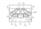
車載カメラが撮影した映像フレーム中の複数の検知枠の例を図4に示す。
図4に示した例では、画像フレーム100A内に7個の検知枠F11~F17が割り当ててある。すなわち、画像フレーム100A内で様々なパターン認識を実施する場合に、認識対象物毎に画像データの処理範囲を検知枠F11~F17のいずれかに限定することにより、処理を高速化すると共に誤検出を減らすことができる。<Example of image frame and detection frame>
FIG. 4 shows an example of multiple detection frames in a video frame captured by an onboard camera.
In the example shown in FIG. 4, seven detection frames F11 to F17 are assigned within the
例えば、図4に示した検知枠F11又はF12の範囲内で、自車両caの前方を走行している他車両cbの像や、レーン左端又は右端の白線212、213の像を認識できる。また、検知枠F14の範囲内で、自車両caの車体端部caLやレーン左端の白線212を認識できる。また、検知枠F16の範囲内で、自車両caの車体端部caRやレーン右端の白線213を認識できる。また、検知枠F13の範囲内で、左側に隣接するレーン内に存在する他車両などを認識できる。また、検知枠F17の範囲内で、右側に隣接するレーン内に存在する他車両などを認識できる。 For example, within the range of the detection frame F11 or F12 shown in FIG. 4, the image of the other vehicle cb running in front of the own vehicle ca and the images of the
<あおり運転評価の処理手順>
図5は、車両におけるあおり運転を評価するための主要な処理手順を示すフローチャートである。図1に示したデジタルタコグラフ10内のCPU11は、図5に示した処理手順を走行中に実行することにより、自車両caの運転者の運転行為によるあおり運転をリアルタイムで検知できる。<Processing procedure for evaluation of tailgate driving>
FIG. 5 is a flowchart showing a main processing procedure for evaluating tailgate driving in a vehicle. The
また、図1に示した事務所PC30内のCPU31は、メモリカード65から入力された運行データを解析する際に、図5に示した処理手順を実行することにより、乗務員の運転状況の評価として、あおり運転の有無を把握することが可能になる。つまり、図5に示した処理手順は、デジタルタコグラフ10および事務所PC30の少なくとも一方が実行することになる。 In addition, when analyzing the operation data input from the
図5に示した処理手順をデジタルタコグラフ10のCPU11が実行する場合の動作について以下に説明する。
CPU11は、ステップS11で自車両caと他車両cbとの間の最新の車間距離Labを計測し、この車間距離Labに相当する時間的な余裕を車間時間Tabとして算出する。車間時間Tabは、例えば車間距離Labと自車両caの走行速度Svaとから求めることができる。あるいは、自車両caと他車両cbの相対速度を用いて車間時間Tabを算出してもよい。The operation when the
In step S11, the
車間距離Labは、例えば車載カメラ23の撮影した映像に基づいて算出することが可能である。また、公知の様々なセンサを用いて車間距離Labを検出してもよい。自車両caの走行速度Svaは、例えば車速センサ51の出力から得ることができる。また、自車両caと他車両cbの相対速度は、車間距離Labの変化から算出できる。 The inter-vehicle distance Lab can be calculated, for example, based on the image captured by the vehicle-mounted
CPU11は、ステップS12でS11の車間時間Tabと事前に定めた閾値Ktとを比較し、車間距離の異常接近の有無を識別する。車間時間Tabが閾値Ktを超えている場合は、車間距離が正常である通常走行状態とみなし、S12からS13を通ってS11に戻り、同じ処理を繰り返す。 In step S12, the
CPU11は、ステップS12で白線認識の統計量を学習する。すなわち、自車両caの走行中レーン左右の白線212、213の認識状態に基づいて、通常走行状態における自車両caの走行軌跡221aの特性を把握するために必要な統計量を算出する。具体的には、図3に示した横方向距離DL、DLc、DR、DRcの1つ又は複数を検出し、その時系列変化のデータを統計的に処理して、走行軌跡221aの形状に関する通常走行状態の統計量を把握し、これを逐次更新する。具体的な統計量としては、変化量の振幅、周波数、分散値などの少なくとも1つを用いる。 The
CPU11は、車間時間Tabが閾値Kt以下の場合は、異常接近状態とみなしてS12からS14に進み、白線認識の統計量を計測する。すなわち、自車両caの走行中レーン左右の白線212、213の認識状態に基づいて、現在の走行状態における自車両caの走行軌跡221aの特性を把握するために必要な統計量を算出する。具体的には、図3に示した横方向距離DL、DLc、DR、DRcの1つ又は複数を検出し、その時系列変化のデータを統計的に処理して、走行軌跡221aの形状に関する最新の統計量を把握し、これを逐次更新する。具体的な統計量としては、変化量の振幅、周波数、分散値などの少なくとも1つを用いる。 When the time headway Tab is equal to or less than the threshold value Kt, the
CPU11は、ステップS15で、S14の統計量Vs1と、S13で学習した通常走行状態の統計量Vs0とを比較する。そして、事前に定めた閾値Ksを利用して「Vs1-Vs0≧Ks」の条件を満たすか否かを識別し、条件を満たす場合は次のステップS16に進み「あおり運転」であると判定する。 In step S15, the
つまり、車間時間Tabから自車両caが他車両cbに異常接近していることをデジタルタコグラフ10が認識し、且つ走行軌跡221aなどの蛇行状態を表す統計量Vs1が、通常走行状態で学習した統計量Vs0に比べて異常に大きい場合に、「あおり運転」をデジタルタコグラフ10が検出する。 That is, the
走行軌跡221aの形状などについては運転者個人の運転の癖などの影響が反映されるので、意図的な蛇行運転か否かを事前に定めた閾値で判定することは難しい。しかし、図5に示した処理手順を実行する場合には、通常走行状態において横方向距離DL、DLc、DR、DRcなどの統計量を学習し、学習した統計量に対する変化量に基づいてあおり運転を判定するので、運転者個人の運転の癖などの影響を排除できる。つまり、精度の高い判定が可能になる。 Since the shape of the
また、メモリカード65に記録された運行データを事務所PC30が解析する際にも、事務所PC30が、上記と同様に図5の処理手順を実行することにより、「あおり運転」を正しく評価することができる。すなわち、図5の処理手順を実行するために必要な情報が運行データとしてメモリカード65上に記録されている場合には、事務所PC30も「あおり運転」を評価できる。 Also, when the
図5の処理手順を実行するために必要な情報は、車載カメラ23が撮影した映像、車間距離、車速、走行軌跡221aの蛇行に関連のある統計量、左右ウインカーの操作情報などの時系列データである。 Information necessary for executing the processing procedure of FIG. 5 includes time-series data such as images captured by the vehicle-mounted
<車載器の動作例>
あおり運転検知の場合の車載器の動作例を図6に示す。すなわち、図5に示したような処理手順の機能をデジタルタコグラフ10が搭載している場合に、デジタルタコグラフ10が図6に示した動作を実行することにより、「あおり運転」の評価結果を有効に活用できる。<Operation example of on-board device>
Fig. 6 shows an example of the operation of the vehicle-mounted device when tailgating is detected. That is, when the
CPU11は、図5のS16で「あおり運転」を検出した場合に、図6のS21からS22の処理に進む。ステップS22では、CPU11は、例えば「危険な運転状態を検出しました、安全運転を心がけましょう」のような警報の音声メッセージをスピーカ20から疑似音声として出力する。 The
CPU11は、次のステップS23で、「あおり運転」のイベントが発生した事実を表すデータを、運行情報として運行情報テーブルTB1に記録する。また、このイベントを後で再評価できるように、当該イベントに関連のあるデータを同時に運行情報テーブルTB1に記録する。具体的には、車載カメラ23が撮影した映像、車間距離、車速、走行軌跡221aの蛇行に関連のある統計量、左右ウインカーの操作情報、ブレーキの操作情報などを記録する。運行情報テーブルTB1は例えばメモリカード65上に配置する。 In the next step S23, the
CPU11は、デジタルタコグラフ10が事務所PC30と通信するための無線通信機能を搭載しているか否かをS24で識別し、搭載している場合は次のS25に進む。ステップS25では、CPU11は「あおり運転」のイベントの発生を表すデータを、通信部24、無線基地局8、ネットワーク70を経由して事務所PC30へ送信する。 In S24, the
事務所PC30を管理している管理者は、事務所PC30が各車両のデジタルタコグラフ10から「あおり運転」のイベント発生を表すデータを受信した場合にはそれを把握することができる。そして、事務所PC30は管理者の操作により、所定の音声メッセージをネットワーク70および無線基地局8を経由して、該当する車両上のデジタルタコグラフ10に対して送信することができる。 The administrator who manages the
CPU11は、事務所PC30から音声等のメッセージを受信した場合に、S26からS27の処理に進み、受信したメッセージをスピーカ20等を利用して運転者に報知する。 When the
<処理手順の変形例>
図7は、車両におけるあおり運転を評価するための処理手順の変形例を示すフローチャートである。デジタルタコグラフ10のCPU11が図7の処理手順を実行する場合の動作について以下に説明する。<Modified Example of Processing Procedure>
FIG. 7 is a flow chart showing a modification of the processing procedure for evaluating tailgate driving in a vehicle. The operation when the
CPU11は、図5のS11と同様に、車間距離Labの計測および車間時間Tabの算出を繰り返し実行する。そして、車間時間Tabから通常走行状態であることを検出している間はS31からS32に進み、走行軌跡221aの統計量に関する学習処理を実施する。 The
CPU11は、車間時間Tabにより自車両caが他車両cbに異常接近した状態を認識すると、S31からS33に進み、図5のS15と同様に走行軌跡221aに関する統計量を比較して異常な蛇行運転か否かを識別する。 When the
CPU11は、S33で異常な蛇行運転を検知した場合はS34に進み、右ウインカー操作の有無を識別する。S34でウインカー操作を検知しなかった場合は、S34からS35に進み、「あおり運転」であると判定する。一方、S34でウインカー操作を検知した場合は、単なる車線変更の可能性が高いため、S31の処理に戻る。 When the
<処理手順の更なる変形例>
図7に示した処理手順では、ウインカー操作を検出した場合にはあおり運転でないと判定するようになっているが、逆に、ある特定の条件が成立している場合には、ウインカー操作を検出した場合に「あおり運転」であると判定するようにしてもよい。例えば、自車両caが現在走行しているレーンの右側に別のレーンが追い越しレーンとして存在しているか否かを識別する。そして、右ウインカー操作ありを検知したにもかかわらず、右側に追い越しレーンが存在していない場合には、CPU11は「あおり運転」であると判定する。<Further Modified Example of Processing Procedure>
In the processing procedure shown in FIG. 7, when the blinker operation is detected, it is determined that it is not tailgate driving. Conversely, when a certain specific condition is satisfied, the blinker operation is detected. It may be determined that the vehicle is "tilting" when the vehicle is driven. For example, it identifies whether or not another lane exists as an overtaking lane on the right side of the lane in which the vehicle ca is currently traveling. If there is no overtaking lane on the right side even though it is detected that the right turn signal has been operated, the
例えば、図2に示したような状況では、自車両caが右ウインカー操作、すなわち車線変更の合図をした後、現在の走行中の走行レーン200Mから右隣の走行レーン200Rに車線変更して、前方の他車両cbを追い越すことができる。 For example, in the situation shown in FIG. 2, after the own vehicle ca operates the right turn signal, that is, signals to change lanes, it changes lanes from the
一方、走行レーン200Rが存在せず、追い越しのための車線変更ができない状況であるにもかかわらず、自車両caが他車両cbに異常接近した状態で自車両caの運転者が右ウインカー操作を実施する場合は、あおり運転の可能性が高い。したがって、走行軌跡221aの蛇行状態の判定に加え、異常な右ウインカー操作を検知して、「あおり運転」の判定精度を高めることができる。 On the other hand, the driver of the own vehicle ca operates the right turn signal while the own vehicle ca is abnormally close to the other vehicle cb in spite of the fact that the
<運転評価装置および車載器の利点>
上述のデジタルタコグラフ10のように運転評価装置の機能を車載器に搭載した場合には、「あおり運転」のような危険な運転行為をリアルタイムで自動的に検出し警報を出力することができる。これにより、自車両caの運転者に危険な状態であることを意識させ、運転マナーを向上させることが可能になる。また、「あおり運転」のイベント情報を含む運行データをメモリカード65に記録することができ、記録する運行データのデータ容量の増大を抑制しつつ、安全運転の推進に役立つ情報を記録することが可能である。<Advantages of the driving evaluation device and onboard device>
When the function of the driving evaluation device is installed in the vehicle-mounted device like the above-described
また、事務所PC30に運転評価装置の機能を搭載した場合には、メモリカード65に記録された運行データを解析する際に、該当する車両を運行した乗務員の「あおり運転」のような危険な運転行為を管理者が把握することができ、安全運転の指導や教育に役立てることができる。 When the
ここで、上述した本発明の実施形態に係る運転評価装置および車載器の特徴をそれぞれ以下[1]~[5]に簡潔に纏めて列記する。
[1] 車両(自車両ca)上で検出された、もしくは過去に記録された運行情報に基づいて、前記車両における危険運転の評価を実施する運転評価装置であって、
前記運行情報が、前記車両と当該車両の前方を走行している他車両(cb)との車間距離(Lab)に応じて変化する第1の情報(車間時間Tab)と、前記車両の走行レーン(200M)を区画する左右の線(212、213)と前記車両との左右方向の相対的な位置関係に応じて変化する第2の情報(横方向距離DL、DLc、DR、又はDRc)とを含み、
前記第2の情報に基づいて統計量(Vs1)を算出し、前記第1の情報に基づいて前記車間距離が正常範囲より短くなったことを検知した場合に、前記第2の情報の統計量に基づいて危険運転が行われたか否かを判定する運転評価部(CPU11、又は31)、
を備えたことを特徴とする運転評価装置(デジタルタコグラフ10、又は事務所PC30)。Here, the features of the driving evaluation device and the vehicle-mounted device according to the embodiment of the present invention described above are briefly listed in [1] to [5] below.
[1] A driving evaluation device for evaluating dangerous driving in a vehicle (self-vehicle ca) based on operation information detected on the vehicle or recorded in the past,
The operation information includes first information (inter-vehicle time Tab) that changes according to the inter-vehicle distance (Lab) between the vehicle and another vehicle (cb) running in front of the vehicle, and the driving lane of the vehicle. second information (lateral distance DL, DLc, DR, or DRc) that changes according to the relative positional relationship in the left-right direction between the left and right lines (212, 213) that divide (200M) and the vehicle; including
A statistic (Vs1) is calculated based on the second information, and when it is detected that the inter-vehicle distance has become shorter than the normal range based on the first information, the statistic of the second information A driving evaluation unit (
A driving evaluation device (
[2] 前記運転評価部は、前記第1の情報に基づいて前記車間距離が前記正常範囲にあることを検知している状態で、前記第2の情報に基づいて算出した統計量(Vs0)を学習値として取得し、前記学習値を前記危険運転の判定のための閾値に反映する、
ことを特徴とする上記[1]に記載の運転評価装置。[2] The driving evaluation unit calculates a statistic (Vs0) based on the second information while detecting that the inter-vehicle distance is within the normal range based on the first information. is acquired as a learning value, and the learning value is reflected in the threshold value for determining the dangerous driving,
The driving evaluation device according to the above [1], characterized by:
[3] 前記運転評価部は、前記車間距離(Lab)の大きさに、少なくとも前記車両の車速(Sva)を反映して前記正常範囲を設定する(S11、S12)、
ことを特徴とする上記[1]又は[2]に記載の運転評価装置。[3] The driving evaluation unit sets the normal range for the inter-vehicle distance (Lab) by reflecting at least the vehicle speed (Sva) of the vehicle (S11, S12);
The driving evaluation device according to the above [1] or [2], characterized by:
[4] 前記運転評価部は、前記車両におけるウインカー作動の有無を表す情報を、前記危険運転の判定に利用する(S34)、
ことを特徴とする上記[1]乃至[3]のいずれかに記載の運転評価装置。[4] The driving evaluation unit uses information indicating whether or not the blinker is activated in the vehicle to determine the dangerous driving (S34);
The driving evaluation device according to any one of [1] to [3], characterized by:
[5] 上記[1]乃至[4]のいずれかに記載の運転評価装置を搭載した、ことを特徴とする車載器(デジタルタコグラフ10)。[5] An on-vehicle device (digital tachograph 10) characterized in that the driving evaluation device according to any one of [1] to [4] is installed.
5 運行管理システム
8 無線基地局
10 デジタルタコグラフ
11,31 CPU
12A 速度I/F
12B エンジン回転I/F
13 外部入力I/F
14 センサ入力I/F
15 GPS受信部
15a GPSアンテナ
16 カメラI/F
17 記録部
18 カードI/F
19 音声I/F
20,42 スピーカ
21 RTC
22 SW入力部
23,23B 車載カメラ
24,32 通信部
25 電源部
26A 不揮発メモリ
26B 揮発メモリ
27 表示部
28 Gセンサ
29 アナログ入力I/F
30 事務所PC
33 表示部
34 記憶部
35 カードI/F
36 操作部
37 出力部
38 音声I/F
41 マイク
48 外部I/F
51 車速センサ
54 外部記憶装置
56 運行データDB
57 ハザードマップDB
65 メモリカード
70 ネットワーク
100A,100B 画像フレーム
200 道路
200L,200M,200R 走行レーン
211,212,213,214 白線
221a 走行軌跡
F11,F12,F13,F14,F15,F16,F17 検知枠
F21,F22 検知枠
ca 自車両
caL,caR 車体端部
cb 他車両
ARL,ARR 検知領域
Lab 車間距離
Sva,Svb 走行速度
PL,PR 白線位置
Pc 車体中央位置
Dw 車幅
DL,DR,DLc,DRc 横方向距離
TB1 運行情報テーブル5 operation management system 8
12A Speed I/F
12B Engine rotation I/F
13 External input I/F
14 Sensor input I/F
15
17
19 Audio I/F
20, 42
22
30 office PCs
33
36
41
51
57 Hazard Map DB
65
Claims (4)
Translated fromJapanese前記運行情報が、前記車両と当該車両の前方を走行している他車両との車間距離に応じて変化する第1の情報と、前記車両の走行レーンを区画する左右の線と前記車両との左右方向の相対的な位置関係に応じて変化する第2の情報とを含み、
前記第2の情報に基づいて統計量を算出し、前記第1の情報に基づいて前記車間距離が正常範囲より短くなったことを検知した場合に、前記第2の情報の統計量に基づいて危険運転が行われたか否かを判定する運転評価部、
を備え、
前記運転評価部は、前記第1の情報に基づいて前記車間距離が前記正常範囲にあることを検知している状態で、前記第2の情報に基づいて算出した統計量を学習値として取得し、前記学習値を前記危険運転の判定のための閾値に反映する、
ことを特徴とする運転評価装置。A driving evaluation device for evaluating dangerous driving in a vehicle based on operation information detected on the vehicle or recorded in the past,
The operation information includes first information that changes according to the inter-vehicle distance between the vehicle and another vehicle running in front of the vehicle, and left and right lines that divide the driving lane of the vehicle and the vehicle. and second information that changes according to the relative positional relationship in the horizontal direction,
A statistic is calculated based on the second information, and when it is detected that the inter-vehicle distance is shorter than the normal range based on the first information, based on the statistic of the second information a driving evaluation unit that determines whether or not dangerous driving has been performed;
with
The driving evaluation unit acquires a statistic calculated based on the second information as a learning value while detecting that the inter-vehicle distance is within the normal range based on the first information. , reflecting the learned value in a threshold value for determining the dangerous driving;
A driving evaluation device characterized by:
ことを特徴とする請求項1に記載の運転評価装置。The driving evaluation unit sets the normal range for the inter-vehicle distance by reflecting at least the vehicle speed of the vehicle.
The driving evaluation device according to claim 1, characterized in that:
ことを特徴とする請求項1又は請求項2に記載の運転評価装置。The driving evaluation unit uses information indicating whether or not the blinker is activated in the vehicle to determine the dangerous driving.
The driving evaluation device according to claim 1or 2 , characterized in that:
Priority Applications (1)
| Application Number | Priority Date | Filing Date | Title |
|---|---|---|---|
| JP2018148830AJP7146516B2 (en) | 2018-08-07 | 2018-08-07 | Driving evaluation device and in-vehicle device |
Applications Claiming Priority (1)
| Application Number | Priority Date | Filing Date | Title |
|---|---|---|---|
| JP2018148830AJP7146516B2 (en) | 2018-08-07 | 2018-08-07 | Driving evaluation device and in-vehicle device |
Publications (2)
| Publication Number | Publication Date |
|---|---|
| JP2020024580A JP2020024580A (en) | 2020-02-13 |
| JP7146516B2true JP7146516B2 (en) | 2022-10-04 |
Family
ID=69618755
Family Applications (1)
| Application Number | Title | Priority Date | Filing Date |
|---|---|---|---|
| JP2018148830AActiveJP7146516B2 (en) | 2018-08-07 | 2018-08-07 | Driving evaluation device and in-vehicle device |
Country Status (1)
| Country | Link |
|---|---|
| JP (1) | JP7146516B2 (en) |
Families Citing this family (14)
| Publication number | Priority date | Publication date | Assignee | Title |
|---|---|---|---|---|
| JP2021152701A (en)* | 2020-03-24 | 2021-09-30 | 株式会社東芝 | Operation characteristic evaluation device and operation characteristic evaluation program |
| CN115335268A (en) | 2020-03-24 | 2022-11-11 | Jvc建伍株式会社 | Dangerous driving warning device, dangerous driving warning system, and dangerous driving warning method |
| JP7528491B2 (en)* | 2020-03-24 | 2024-08-06 | 株式会社Jvcケンウッド | Dangerous driving warning device, dangerous driving warning system, and dangerous driving warning method |
| JP7437761B2 (en)* | 2020-06-24 | 2024-02-26 | 有限会社Tedix | Aggressive driving detection program, aggressive driving detection device, aggressive driving detection system |
| CN111942397A (en)* | 2020-08-06 | 2020-11-17 | 华南理工大学 | Dangerous driving behavior monitoring method and device and storage medium |
| US20230294720A1 (en)* | 2020-08-20 | 2023-09-21 | Mitsubishi Electric Corporation | Drive assist apparatus and drive assist method |
| JP7439696B2 (en)* | 2020-08-25 | 2024-02-28 | スズキ株式会社 | Driving evaluation device |
| JP2022049189A (en)* | 2020-09-16 | 2022-03-29 | 株式会社デンソーテン | Image recording device and image recording method |
| CN114763145A (en)* | 2021-01-12 | 2022-07-19 | 长沙智能驾驶研究院有限公司 | Driving behavior detection method and device, electronic equipment and storage medium |
| JP7501412B2 (en)* | 2021-03-10 | 2024-06-18 | トヨタ自動車株式会社 | Display control device and display control method |
| US20240104975A1 (en)* | 2022-09-27 | 2024-03-28 | Bendix Commercial Vehicle Systems Llc | System and method for detecting and evaluating bursts of driver performance events |
| US12065159B2 (en) | 2022-10-17 | 2024-08-20 | Toyota Motor Engineering & Manufacturing North America, Inc. | Customizable abnormal driving detection |
| CN117095333B (en)* | 2023-08-29 | 2024-11-29 | 上检智联科技(苏州)有限公司 | A vehicle driving safety supervision system based on vehicle-mounted video monitoring |
| CN120116965B (en)* | 2025-05-13 | 2025-07-29 | 成都赛力斯科技有限公司 | Risk coefficient evaluation method and device for rear vehicle |
Citations (4)
| Publication number | Priority date | Publication date | Assignee | Title |
|---|---|---|---|---|
| JP2006205773A (en) | 2005-01-25 | 2006-08-10 | Fujitsu Ten Ltd | Driving supporting device |
| JP2009199328A (en) | 2008-02-21 | 2009-09-03 | Yazaki Corp | Operation recording and evaluating apparatus for vehicle |
| JP2011227571A (en) | 2010-04-15 | 2011-11-10 | Fujitsu Ltd | Information processing method, information processing program, and information processing apparatus |
| WO2018123344A1 (en) | 2016-12-27 | 2018-07-05 | 本田技研工業株式会社 | Vehicle control device, vehicle control method, and program |
Family Cites Families (1)
| Publication number | Priority date | Publication date | Assignee | Title |
|---|---|---|---|---|
| JP2682291B2 (en)* | 1991-09-10 | 1997-11-26 | トヨタ自動車株式会社 | Drowsiness driving detection device for vehicles |
- 2018
- 2018-08-07JPJP2018148830Apatent/JP7146516B2/enactiveActive
Patent Citations (4)
| Publication number | Priority date | Publication date | Assignee | Title |
|---|---|---|---|---|
| JP2006205773A (en) | 2005-01-25 | 2006-08-10 | Fujitsu Ten Ltd | Driving supporting device |
| JP2009199328A (en) | 2008-02-21 | 2009-09-03 | Yazaki Corp | Operation recording and evaluating apparatus for vehicle |
| JP2011227571A (en) | 2010-04-15 | 2011-11-10 | Fujitsu Ltd | Information processing method, information processing program, and information processing apparatus |
| WO2018123344A1 (en) | 2016-12-27 | 2018-07-05 | 本田技研工業株式会社 | Vehicle control device, vehicle control method, and program |
Also Published As
| Publication number | Publication date |
|---|---|
| JP2020024580A (en) | 2020-02-13 |
Similar Documents
| Publication | Publication Date | Title |
|---|---|---|
| JP7146516B2 (en) | Driving evaluation device and in-vehicle device | |
| US11807231B2 (en) | Electronic device for vehicle and operating method thereof | |
| CN107608388B (en) | Autonomous police vehicle | |
| US8493198B1 (en) | Vehicle and mobile device traffic hazard warning techniques | |
| US11198398B2 (en) | Display control device for vehicle, display control method for vehicle, and storage medium | |
| WO2019165381A1 (en) | Distributed computing resource management | |
| JP7207916B2 (en) | In-vehicle device | |
| WO2017022538A1 (en) | Driving evaluation device | |
| CN117922290A (en) | Vehicle display control device | |
| WO2015174017A1 (en) | In-vehicle apparatus and travel image storage system | |
| KR102319383B1 (en) | Method and apparatus for automatically reporting traffic rule violation vehicles using black box images | |
| US10977882B1 (en) | Driver health profile | |
| JP2021099720A (en) | Dangerous driving determination device, dangerous driving determination method, and dangerous driving determination program | |
| JP6959025B2 (en) | Driving evaluation system | |
| JP6974059B2 (en) | On-board unit and driving support device | |
| JP7057074B2 (en) | On-board unit and driving support device | |
| JP7207912B2 (en) | Driving evaluation system | |
| JP6927787B2 (en) | On-board unit and driving support device | |
| US11912313B2 (en) | Human machine interaction monitor | |
| US20220028258A1 (en) | Warning presentation control device, warning presentation control system, method of controlling warning presentation, and recording medium storing warning presentation control program | |
| CN111216631B (en) | Travel control device, control method, and storage medium storing program | |
| JP2023154315A (en) | Vehicle operation recording system, on-vehicle driving information recording processing system, and drive recorder | |
| JP2018195184A (en) | Vehicle device, safe driving support system, and safe driving support method | |
| JP2022074441A (en) | Driver state estimation device, driver state estimation program, daily operation report generation method, and daily operation report | |
| JP7376271B2 (en) | Onboard equipment |
Legal Events
| Date | Code | Title | Description |
|---|---|---|---|
| A621 | Written request for application examination | Free format text:JAPANESE INTERMEDIATE CODE: A621 Effective date:20210716 | |
| A977 | Report on retrieval | Free format text:JAPANESE INTERMEDIATE CODE: A971007 Effective date:20220531 | |
| A131 | Notification of reasons for refusal | Free format text:JAPANESE INTERMEDIATE CODE: A131 Effective date:20220705 | |
| A521 | Request for written amendment filed | Free format text:JAPANESE INTERMEDIATE CODE: A523 Effective date:20220819 | |
| TRDD | Decision of grant or rejection written | ||
| A01 | Written decision to grant a patent or to grant a registration (utility model) | Free format text:JAPANESE INTERMEDIATE CODE: A01 Effective date:20220920 | |
| A61 | First payment of annual fees (during grant procedure) | Free format text:JAPANESE INTERMEDIATE CODE: A61 Effective date:20220921 | |
| R150 | Certificate of patent or registration of utility model | Ref document number:7146516 Country of ref document:JP Free format text:JAPANESE INTERMEDIATE CODE: R150 | |
| S531 | Written request for registration of change of domicile | Free format text:JAPANESE INTERMEDIATE CODE: R313531 | |
| R350 | Written notification of registration of transfer | Free format text:JAPANESE INTERMEDIATE CODE: R350 | |
| R250 | Receipt of annual fees | Free format text:JAPANESE INTERMEDIATE CODE: R250 |