JP7145852B2 - A device for removing organs from the human or animal body - Google Patents
A device for removing organs from the human or animal bodyDownload PDFInfo
- Publication number
- JP7145852B2 JP7145852B2JP2019525837AJP2019525837AJP7145852B2JP 7145852 B2JP7145852 B2JP 7145852B2JP 2019525837 AJP2019525837 AJP 2019525837AJP 2019525837 AJP2019525837 AJP 2019525837AJP 7145852 B2JP7145852 B2JP 7145852B2
- Authority
- JP
- Japan
- Prior art keywords
- tube
- proximal end
- casing
- gripping arm
- proximal
- Prior art date
- Legal status (The legal status is an assumption and is not a legal conclusion. Google has not performed a legal analysis and makes no representation as to the accuracy of the status listed.)
- Active
Links
Images


Classifications
- A—HUMAN NECESSITIES
- A61—MEDICAL OR VETERINARY SCIENCE; HYGIENE
- A61B—DIAGNOSIS; SURGERY; IDENTIFICATION
- A61B17/00—Surgical instruments, devices or methods
- A61B17/32—Surgical cutting instruments
- A61B17/3205—Excision instruments
- A61B17/3207—Atherectomy devices working by cutting or abrading; Similar devices specially adapted for non-vascular obstructions
- A61B17/320758—Atherectomy devices working by cutting or abrading; Similar devices specially adapted for non-vascular obstructions with a rotating cutting instrument, e.g. motor driven
- A—HUMAN NECESSITIES
- A61—MEDICAL OR VETERINARY SCIENCE; HYGIENE
- A61B—DIAGNOSIS; SURGERY; IDENTIFICATION
- A61B17/00—Surgical instruments, devices or methods
- A61B17/00234—Surgical instruments, devices or methods for minimally invasive surgery
- A—HUMAN NECESSITIES
- A61—MEDICAL OR VETERINARY SCIENCE; HYGIENE
- A61B—DIAGNOSIS; SURGERY; IDENTIFICATION
- A61B17/00—Surgical instruments, devices or methods
- A61B17/22—Implements for squeezing-off ulcers or the like on inner organs of the body; Implements for scraping-out cavities of body organs, e.g. bones; for invasive removal or destruction of calculus using mechanical vibrations; for removing obstructions in blood vessels, not otherwise provided for
- A61B17/22031—Gripping instruments, e.g. forceps, for removing or smashing calculi
- A61B17/22032—Gripping instruments, e.g. forceps, for removing or smashing calculi having inflatable gripping elements
- A—HUMAN NECESSITIES
- A61—MEDICAL OR VETERINARY SCIENCE; HYGIENE
- A61B—DIAGNOSIS; SURGERY; IDENTIFICATION
- A61B17/00—Surgical instruments, devices or methods
- A61B17/32—Surgical cutting instruments
- A61B17/3205—Excision instruments
- A—HUMAN NECESSITIES
- A61—MEDICAL OR VETERINARY SCIENCE; HYGIENE
- A61B—DIAGNOSIS; SURGERY; IDENTIFICATION
- A61B17/00—Surgical instruments, devices or methods
- A61B17/34—Trocars; Puncturing needles
- A61B17/3417—Details of tips or shafts, e.g. grooves, expandable, bendable; Multiple coaxial sliding cannulas, e.g. for dilating
- A61B17/3421—Cannulas
- A61B17/3423—Access ports, e.g. toroid shape introducers for instruments or hands
- A—HUMAN NECESSITIES
- A61—MEDICAL OR VETERINARY SCIENCE; HYGIENE
- A61B—DIAGNOSIS; SURGERY; IDENTIFICATION
- A61B17/00—Surgical instruments, devices or methods
- A61B17/00234—Surgical instruments, devices or methods for minimally invasive surgery
- A61B2017/00287—Bags for minimally invasive surgery
- A—HUMAN NECESSITIES
- A61—MEDICAL OR VETERINARY SCIENCE; HYGIENE
- A61B—DIAGNOSIS; SURGERY; IDENTIFICATION
- A61B17/00—Surgical instruments, devices or methods
- A61B17/00234—Surgical instruments, devices or methods for minimally invasive surgery
- A61B2017/00353—Surgical instruments, devices or methods for minimally invasive surgery one mechanical instrument performing multiple functions, e.g. cutting and grasping
- A—HUMAN NECESSITIES
- A61—MEDICAL OR VETERINARY SCIENCE; HYGIENE
- A61B—DIAGNOSIS; SURGERY; IDENTIFICATION
- A61B17/00—Surgical instruments, devices or methods
- A61B2017/00535—Surgical instruments, devices or methods pneumatically or hydraulically operated
- A61B2017/00561—Surgical instruments, devices or methods pneumatically or hydraulically operated creating a vacuum
- A61B2017/00566—Surgical instruments, devices or methods pneumatically or hydraulically operated creating a vacuum fixation of form upon application of vacuum
- A—HUMAN NECESSITIES
- A61—MEDICAL OR VETERINARY SCIENCE; HYGIENE
- A61B—DIAGNOSIS; SURGERY; IDENTIFICATION
- A61B17/00—Surgical instruments, devices or methods
- A61B17/30—Surgical pincettes, i.e. surgical tweezers without pivotal connections
- A61B2017/306—Surgical pincettes, i.e. surgical tweezers without pivotal connections holding by means of suction
- A—HUMAN NECESSITIES
- A61—MEDICAL OR VETERINARY SCIENCE; HYGIENE
- A61B—DIAGNOSIS; SURGERY; IDENTIFICATION
- A61B2217/00—General characteristics of surgical instruments
- A61B2217/002—Auxiliary appliance
- A61B2217/005—Auxiliary appliance with suction drainage system
Landscapes
- Health & Medical Sciences (AREA)
- Surgery (AREA)
- Life Sciences & Earth Sciences (AREA)
- Medical Informatics (AREA)
- Nuclear Medicine, Radiotherapy & Molecular Imaging (AREA)
- Engineering & Computer Science (AREA)
- Biomedical Technology (AREA)
- Heart & Thoracic Surgery (AREA)
- Molecular Biology (AREA)
- Animal Behavior & Ethology (AREA)
- General Health & Medical Sciences (AREA)
- Public Health (AREA)
- Veterinary Medicine (AREA)
- Vascular Medicine (AREA)
- Orthopedic Medicine & Surgery (AREA)
- Surgical Instruments (AREA)
Description
Translated fromJapanese本発明は、人体または動物の体から臓器を除去するための装置に関する。 The present invention relates to a device for removing organs from the human or animal body.
このタイプの装置は、特に疾患または他の悪影響の結果として苦しんできたそしてもはやそれらの機能を適切に果たすことができないかまたは壊死に苦しんでいる内臓の除去に役立つ。特に、この種の装置は病的子宮を除去することを目的としている。上述のタイプの多くの装置は、内視鏡的に作動し、少なくとも2つの内視鏡を備え、その内の1つは除去されるべき臓器を切断するための鉗子を備える。しなしながら、従来技術の装置を使用する際に、除去される臓器の領域において体内に無菌環境を作り出すことは不可能であったか、または極端な努力を要したため、除去された臓器の残留物および残留粒子は体内に残り、それによって体内の望ましくない汚染がもたらされていた。特に従来技術の装置に関する問題は、重力によって切断された臓器がその下の身体部分に落下することに起因する。これは、汚染を助長するだけでなく、無菌性の問題ももたらす。 Devices of this type are particularly useful for removing internal organs that have suffered as a result of disease or other adverse effects and can no longer perform their function properly or are suffering from necrosis. In particular, devices of this kind are intended to remove a diseased uterus. Many devices of the type described above operate endoscopically and include at least two endoscopes, one of which includes forceps for cutting the organ to be removed. However, when using prior art devices, it was not possible or required extreme efforts to create a sterile environment within the body in the area of the removed organ, resulting in residue of the removed organ and Residual particles remained in the body, thereby resulting in unwanted contamination of the body. A problem, particularly with prior art devices, results from gravity causing the severed organ to fall into the underlying body part. This not only encourages contamination, but also poses sterility problems.
本発明の1つの目的は、除去される臓器の領域において身体内に実質的に無菌環境を容易に作り出すのを助ける上述のタイプの改良された装置を提供することである。さらに、除去された臓器の残留物および残留粒子による汚染を実質的に防止することである。 One object of the present invention is to provide an improved apparatus of the type described above that facilitates the creation of a substantially sterile environment within the body in the area of the organ to be removed. A further object is to substantially prevent contamination of removed organs with residue and residual particles.
この目的は、近位端および遠位端を備え、その近位端を有する体に部分的に導入されるように意図されている管を用いて、人体または動物の体から臓器を除去するための装置を備える本発明によって達成される。それにより、管の遠位端を吸引空気源に接続することができ、管の近位端は、除去される臓器と吸引係合するように具体化される。前記装置は、近位端と遠位端とを有する管を少なくとも部分的に囲む管状ケーシングを備える。それにより管に取り付けられ、さらにハンドリング装置を備える。好ましくは、前記装置は、管状ケーシングをその近位端で開きまたは延ばし、それを臓器の周囲に案内または配置するために、好ましくは管に配置されかつ具体化される。そして、前記装置は閉鎖装置を備える。これは、管状ケーシングの近位端と、好ましくはその近位端の領域において管内に設けられている粉砕装置とを閉じるように具体化されている。 The purpose is to remove organs from the human or animal body using a tube comprising a proximal end and a distal end and intended to be partially introduced into the body with its proximal end. This is accomplished by the present invention comprising an apparatus for: The distal end of the tube can thereby be connected to a source of suction air, and the proximal end of the tube is embodied for suction engagement with the organ to be removed. The device comprises a tubular casing that at least partially surrounds a tube having proximal and distal ends. It is thereby attached to the tube and further comprises a handling device. Preferably, the device is arranged and embodied in a tube, preferably in order to open or extend the tubular casing at its proximal end and guide or place it around the organ. The device then comprises a closing device. It is embodied to close the proximal end of the tubular casing and the comminuting device preferably provided within the tube in the region of its proximal end.
本発明の管状ケーシングの使用は、その近位端で最初に開かれまたは延ばされ、続いて臓器の周囲に案内または配置され、そして最後にその近位端で閉じられる。可能な限り必要な無菌性を達成する簡単な方法で安全にそして完全に除去されるべき臓器を囲むことを可能にする。同時に、除去されるべき臓器の残留物または残留粒子による汚染を防ぐ。本発明によれば、これは、体内に挿入される管に配置され具体化され、その近位端で管状ケーシングを開きまたは延ばすように設計され、臓器の周囲に管状ケーシングを案内または配置するように設計されたハンドリング装置と、管状ケーシングの近位端を閉じるように具体化された閉鎖装置を有することによって達成される。“管に配置された”という用語はまた、管に沿ったおよび/または管に隣接したハンドリング装置の位置、ならびに管に取り付けられていない配置を指すこともある。閉鎖装置によって管状ケーシングの近位端を閉鎖した後、管状ケーシングは小袋の形状をとり、これは除去されるべき臓器を収容する。 Use of the tubular casing of the present invention is first opened or extended at its proximal end, then guided or placed around the organ, and finally closed at its proximal end. It allows to surround the organ to be removed safely and completely in a simple way that achieves the necessary sterility as much as possible. At the same time, it prevents contamination of the organs to be removed with residues or residual particles. According to the invention, it is arranged and embodied in a tube that is inserted into the body and is designed to open or extend the tubular casing at its proximal end and to guide or position the tubular casing around the organ. This is achieved by having a handling device designed to and a closure device embodied to close the proximal end of the tubular casing. The term "placed on the tube" may also refer to the location of the handling device along and/or adjacent to the tube, as well as placements that are not attached to the tube. After closing the proximal end of the tubular casing with the closure device, the tubular casing assumes the shape of a sachet, which contains the organ to be removed.
本発明はまた、体から除去されるべき臓器を除去するための簡単であるが効果的な解決策を提供し、それは必要な無菌性のための厳しい要件を満たす。これに関して、本発明は、管の遠位端を吸引空気源に接続することができ、管の近位端が除去されるべき臓器と吸引係合するように具体化されることを意図している。その結果、除去されるべき臓器は、管の近位端に接続された管状ケーシングによって袋状に閉じ込められ、その結果、周囲から分離される。すなわち、体の残りの部分は、管の近位端に吸い込まれる。本発明はさらに、吸引された空気源によって管の近位端に引き込まれている間に、除去されるべき臓器を粉砕する目的で、その近位端の領域において管内に配置されかつ具体化された粉砕装置を提供する。粉砕は、除去されるべき臓器の容積、ひいては小袋のようにその臓器を収容する閉じた管状ケーシングの容積も減少させ、それは除去されるべき臓器が管を通して引き出されることができる容易さを改善する。 The present invention also provides a simple yet effective solution for removing organs to be removed from the body, which meets stringent requirements for necessary sterility. In this regard, the present invention is intended to be embodied such that the distal end of the tube can be connected to a source of suction air and the proximal end of the tube is in suction engagement with the organ to be removed. there is As a result, the organ to be removed is bagged by the tubular casing connected to the proximal end of the tube and thus isolated from the surroundings. That is, the rest of the body is sucked into the proximal end of the tube. The present invention further provides a device positioned and embodied within the tube in the region of its proximal end for the purpose of crushing the organ to be removed while being drawn into the tube's proximal end by an aspirated air source. to provide a crushing device. Crushing reduces the volume of the organ to be removed, and thus also the volume of the closed tubular casing containing that organ like a sachet, which improves the ease with which the organ to be removed can be drawn through the tube. .
この時点で、“近位”という用語は、ドイツ語のDuden辞書によれば“体の中心に近い”という意味であり、この文脈での用語“遠位”とは、ドイツ語のDuden辞書によれば、“体の中心からより遠い”という意味であり、臓器の除去前に体内で除去されるべき臓器に対する位置を指す。 At this point, the term "proximal" according to the German Duden dictionary means "near the center of the body", and the term "distal" in this context means according to the German Duden dictionary. means "farther from the center of the body" and refers to the position relative to the organ to be removed within the body prior to removal of the organ.
本発明の好ましい実施形態およびさらなる発展形態は、従属請求項に記載されている。 Preferred embodiments and further developments of the invention are described in the dependent claims.
その結果、管に対してハンドリング装置を、管の長手方向に沿って伸張された近位端と最終端との間で移動可能に配置することが実際的である。好ましいさらなる発展形態において、ハンドリング装置は、効果的に除去されるべき臓器のそれぞれの位置に応じて臓器の周囲に管状ケーシングを配置するために、管の横断方向に沿って移動可能にも配置される。 As a result, it is practical to dispose the handling device movably relative to the tube between a proximal end and a terminal end extending along the length of the tube. In a preferred further development, the handling device is also arranged movably along the transverse direction of the duct in order to arrange the tubular casing around the organ according to the respective position of the organ to be effectively removed. be.
ハンドリング装置の特に好ましい設計は、対向する位置にある把持アームを備え、その各々が近位端と遠位端とを有することを特徴とする。そして、それは、好ましくは後者の近位端の領域において、管状ケーシングを解放可能に把持するように具体化される。 A particularly preferred design of the handling device is characterized in that it comprises opposed grasping arms, each having a proximal end and a distal end. And it is embodied to releasably grip the tubular casing, preferably in the region of the proximal end of the latter.
有利には、把持アームは、好ましくはそれらの近位端の領域に、管状ケーシングを、好ましくはその近位端で、把持アームに取り外し可能に固定するように具体化された固定手段を備える。 Advantageously, the gripping arms are provided, preferably in the region of their proximal ends, with fastening means embodied to removably fasten the tubular casing, preferably at its proximal end, to the gripping arms.
便宜上、把持アームは管の長手方向に沿って整列している。 For convenience, the gripping arms are aligned along the length of the tube.
好ましくは、把持アームは弾性を有するように具体化され、好ましくは例えば横方向に管の長手方向の範囲に対してある角度で配置される。好ましいさらなる発展形態では、把持アームの弛緩状態において、それぞれ対向する把持アームの近位端は、管の直径よりも小さい距離離れている。近位端と遠位端との間に位置する把持アームの中央部分は、管に対して外側に湾曲している。そのため、少なくとも半径方向に沿って最も外側にある位置では、それぞれの対向する把持アームまでの中央部分の距離は、把持アームの近位端間の距離よりも大きく、好ましくは管の直径よりも大きい。このような把持アームの形状は、管状ケーシングを臓器の周囲に案内または配置するだけでなく、閉じた管状ケーシングによって囲まれた臓器を把持アームの中央部分の領域にしっかりと保持するためにも特に有利である。さらに、形状と組み合わせた弾性はまた、把持アームが最初に弾性によって加えられる力に抗してそれらの近位端で開かれることを確実にし、それはその近位端での管状ケーシングの開放または拡大をもたらす。そして、続いて、弾力性によって発生した予張力は、臓器が閉じ込められた後に把持アームの近位端をそれらの閉鎖位置に戻すために使用される。 Preferably, the gripping arms are embodied elastically and are preferably arranged at an angle to the longitudinal extent of the tube, for example laterally. In a preferred further development, in the relaxed state of the gripping arms, the respective proximal ends of the gripping arms are separated by a distance less than the diameter of the tube. A central portion of the gripping arm, located between the proximal and distal ends, curves outwardly with respect to the tube. Therefore, at least in the radially outermost position, the distance of the central portion to each opposing gripping arm is greater than the distance between the proximal ends of the gripping arms, preferably greater than the diameter of the tube. . Such a gripping arm shape is particularly not only for guiding or positioning the tubular casing around the organ, but also for firmly holding the organ surrounded by the closed tubular casing in the area of the central portion of the gripping arm. Advantageous. Furthermore, the elasticity combined with the shape also ensures that the gripping arms are initially opened at their proximal end against the force exerted by the elasticity, which causes the opening or expansion of the tubular casing at its proximal end. bring. An elastically generated pre-tension is then subsequently used to return the proximal ends of the grasping arms to their closed position after the organ has been trapped.
さらなる好ましい実施形態では、管の外側面はその長手方向に沿ってガイド溝を備え、その中に把持アームは溝の長手方向に沿って移動可能に収容され、この配置は、ハンドリング装置の近位最終位置において、把持アームが、それらの近位端に接続された部分で管の近位端を越えて延び、したがって露出されるように設計されている。これにより、把持アームの特に広範囲の動きが容易になる。 In a further preferred embodiment, the outer surface of the tube is provided along its longitudinal direction with a guide groove, in which the gripping arm is housed movably along the longitudinal direction of the groove, this arrangement being proximal to the handling device. In the final position, the gripping arms are designed to extend beyond the proximal end of the tube at the portion connected to their proximal end and thus be exposed. This facilitates a particularly wide range of movement of the gripping arm.
ハンドリング装置は、好ましくは散散要素を備え、これは管状ケーシングをその近位端で開くか延ばし、それを臓器の周りに案内または配置するために、ハンドリング装置の移動中にそれらが把持アームをその近位最終位置まで少なくとも部分的に広げることができるように具体化されている。 The handling device preferably comprises a diffuser element which opens or extends the tubular casing at its proximal end so that during movement of the handling device they move the gripping arms in order to guide or position it around the organ. It is embodied to be at least partially extendable to its proximal final position.
この実施形態の好ましいさらなる発展形態では、拡散要素は、その近位端の領域内で管に配置されガイド面を有する。これは管の外側と後者の近位端との間に上昇すると、これに把持アームは接触することができるとされている。したがって、それらの近位端または管の近位端における拡散要素のガイド面の半径方向距離は、管の半径よりも大きく、その結果、それらの近位端または管の近位端で対向する拡散要素のガイド面間の半径方向の間隔は管の直径よりも大きい。その結果、この好ましいさらなる発展形態の拡散要素は、把持アームをそれらと接触して展開するように円錐状に作用する。長手方向に沿って延びるガイド溝が管の外側または内側に形成されている。拡散要素はこれらのガイド溝内に優先的に配置されてもよく、それらのガイド面はガイド溝の底部から立ち上がってもよい。 In a preferred further development of this embodiment, the diffusion element has a guide surface arranged on the tube in the region of its proximal end. It is said that the gripping arm can contact it when it rises between the outside of the tube and the proximal end of the latter. Therefore, the radial distance of the guide surfaces of the diffusing elements at their proximal ends or the proximal ends of the tubes is greater than the radius of the tubes, resulting in the opposing diffusing elements at their proximal ends or the proximal ends of the tubes. The radial spacing between the guide surfaces of the elements is greater than the tube diameter. As a result, the diffusing elements of this preferred further development act conically to deploy the gripping arms in contact with them. A longitudinally extending guide groove is formed on the outside or inside of the tube. The diffusing elements may be preferentially arranged within these guide grooves and their guide surfaces may rise from the bottom of the guide grooves.
好ましいさらなる発展形態においては、拡散要素は、いくつかの距離だけ離れて配置され、1つの拡散要素が各把持アームと関連付けられており、拡散要素から把持アームを解放するために、一方の管および/または他方の把持アームは、拡散要素に横方向の次の位置に把持アームを提供するために、互いに対して相対的な運動を行うことができる。したがって、把持アームに対する管の横方向の変位、または管に対する把持アームの横方向の変位、あるいは互いに対する管と把持アームとの対応する結合の横方向の変位は、把持アームを拡散要素から滑り落とし、ひいては把持アームを閉じさせる。 In a preferred further development, the diffusing elements are arranged some distance apart, one diffusing element being associated with each gripping arm, and in order to release the gripping arm from the diffusing element, one tube and one /or the other gripping arm can move relative to each other to present the gripping arm to the next position laterally to the diffusing element. Thus, lateral displacement of the tube relative to the gripping arm, or of the gripping arm relative to the tube, or of the corresponding coupling of the tube and the gripping arm relative to each other, causes the gripping arm to slide off the diffusing element. , which in turn causes the gripping arms to close.
好ましくは、把持アームはそれらの遠位端の領域で互いに接続されている。これは、特に近位端位置への移動中の把持アームの取り扱いを単純化する。有利なさらなる発展形態は、把持アームがそれらの遠位端に取り付けられている環状要素を備えており、これは好ましくは操作要素として使用することができる。 Preferably, the gripping arms are connected to each other in the region of their distal ends. This simplifies handling of the gripping arm, especially during movement to the proximal end position. An advantageous further development comprises annular elements to which the gripping arms are attached at their distal ends, which can preferably be used as operating elements.
閉鎖装置はハンドリング装置に設けられていると好都合である。把持アームが使用される場合、閉鎖装置は、好ましくは、その露出する、すなわち近位端で、把持アームに設けられている閉鎖手段を備える。さらに、閉鎖装置は、好ましくは、管状ケーシングの近位端に設けられたアイまたは小穴、ならびにアイまたは小穴に通すことができる少なくとも1つの糸またはワイヤを含むことができ、その結果として、管状ケーシングの近位端部の閉鎖工程は縫合工程の方法で行われる。 Advantageously, the closing device is provided on the handling device. If a gripping arm is used, the closure device preferably comprises, at its exposed or proximal end, closure means provided on the gripping arm. Further, the closure device can preferably include an eye or eyelet provided at the proximal end of the tubular casing and at least one thread or wire that can be threaded through the eye or eyelet, so that the tubular casing Closing the proximal end of the is done by way of a suture process.
除去されるべき臓器の特に効果的な粉砕を提供するために、粉砕装置は少なくとも1つの回転可能に支持された切断ブレードを含むことが好ましい。 To provide particularly effective comminution of the organ to be removed, the comminution device preferably includes at least one rotatably supported cutting blade.
スリーブは、好ましくは、体の表面上に配置するか、管がスリーブを通って延び、スリーブに対して移動可能であることにより、体の表面に挿入されるように設けられている。このタイプのスリーブは、体の表面上の位置に装置を固定することを容易にし、また、管を臓器の除去されるべき方向に向かって体内に挿入したとき、管のより簡単でより正確な整列も可能にする。 The sleeve is preferably arranged to be inserted into the body surface by placing it on the body surface or by having the tube extend through the sleeve and be movable relative to the sleeve. This type of sleeve facilitates securing the device in position on the surface of the body and also makes it easier and more precise to remove the tube when the tube is inserted into the body in the direction the organ is to be removed. It also allows alignment.
把持アームが含まれる場合、把持アームが優先的にスリーブの内側と管の外側との間に配置され、スリーブの内側と管の外側と接触する。この種の構成は、把持アームの確実な案内を容易にする。把持アームが近位端と遠位端との間に位置する外向きに湾曲形状を有する中央部分で具体化される場合、この配置は、把持アームの湾曲形状のために広がることになる。把持アームがいわゆる開始位置にある、ハンドリング装置の後退した遠位最終位置では、管の外側とスリーブの内側との間の間隙は、実質的な移動の余地を与えないから、把持アームは、スリーブによって実質的に完全に伸張された状態にされ、その結果として実質的に完全に伸張される。その結果、この状態も強制的制約と呼ぶことができ、これは、上述の構成から生じており、把持アームに他の選択を提供するのではなく、完全に延在する形状をとることを意図していない。ハンドリング装置がその近位最終位置に向かう方向に動かされ、それに対応して把持アームが伸びると、次に、少なくとも把持アームの外側に湾曲した中央部分の湾曲形状が、把持アームの中央部分をスリーブの内側に向かって外側に押す力を発生させるのに寄与する限り、把持アームの中央部分の湾曲形状は、最初に把持アームを広げる。把持アームの外側に湾曲した中央部分がスリーブの外側に露出した時、そして把持アームがもはやスリーブから力の影響を受けなくなった時より後に、再び把持アームを閉じる。 If gripping arms are included, the gripping arms are preferentially positioned between the inside of the sleeve and the outside of the tube and contact the inside of the sleeve and the outside of the tube. A configuration of this kind facilitates reliable guidance of the gripping arms. If the gripping arms are embodied with a central portion having an outwardly curved shape located between the proximal and distal ends, this arrangement will widen due to the curved shape of the gripping arms. In the retracted distal final position of the handling device, in which the gripping arms are in the so-called starting position, the gripping arms are in the sleeve because the clearance between the outside of the tube and the inside of the sleeve does not provide substantial room for movement. is substantially fully stretched by and as a result substantially fully stretched. As a result, this condition can also be called a forced constraint, which arises from the configuration described above and is intended to take on a fully extended shape rather than offering other options for the gripping arms. not. When the handling device is moved in a direction toward its proximal final position and the gripping arms are correspondingly extended, then the curved shape of at least the outwardly curved central portion of the gripping arms causes the central portion of the gripping arms to be sleeved. The curved shape of the central portion of the gripping arms initially spreads the gripping arms as long as it contributes to generating an outward pushing force towards the inside of the . After the outwardly curved central portion of the gripping arm is exposed outside the sleeve and the gripping arm is no longer subject to forces from the sleeve, the gripping arm is closed again.
好ましいさらなる発展形態では、スリーブの内側は、ハンドリング装置の移動の方向に沿って延びたガイド溝を備えている。これは把持アームが溝の長手方向に沿って移動可能に配置され、そして配置は、ハンドリング装置の近位最終位置において、それらの近位端に隣接するそれらの部分を有する把持アームが管の近位端を越えて突き出し、その結果、露出されるように設計されている。 In a preferred further development, the inner side of the sleeve is provided with guide grooves extending along the direction of movement of the handling device. This is because the gripping arms are arranged movably along the length of the groove, and the arrangement is such that, in the final proximal position of the handling device, the gripping arms with their portions adjacent their proximal ends are adjacent to the tube. It is designed to protrude beyond the extremity and thus be exposed.
スリーブは、体の表面上で信頼性の高い軸受接触を容易にするためにフランジ状のリムを有するのが好ましい。 The sleeve preferably has a flanged rim to facilitate reliable bearing contact on the body surface.
さらなる好ましい実施形態では、管状ケーシングは、空間を形成しながら内側ケーシングと間隔を空けて取り囲み、加圧空気源を、内側ケーシングと外側ケーシングとの間に形成された間隙に接続することができる、内側ケーシングと外側ケーシングとを有する二重ケーシングとして具体化される。加圧空気源を接続すると、内側ケーシングと外側ケーシングとの間の間隙を膨張させ加圧することが容易になる。これには3つの効果がある。除去されるべき臓器の周りにより大きな空間が作られ、それは装置の取り扱い、特に、ハンドリング装置の取り扱いを容易にする。さらに、除去される臓器の体内環境は安定化している。最後に、そしてこれは非常に重要な側面であり、除去されるべき臓器は加圧され、それは次に臓器の圧縮をもたらし、それは次に吸引作用のためにそこに広がる負圧に加えて作用し、スピードアップし、そしてそれ故、管を通しての臓器の除去を促進する。 In a further preferred embodiment, the tubular casing surrounds the inner casing in a spaced apart manner forming a space, and a source of pressurized air can be connected to the gap formed between the inner casing and the outer casing. It is embodied as a double casing with an inner casing and an outer casing. Connecting a source of pressurized air facilitates inflating and pressurizing the gap between the inner and outer casings. This has three effects. A larger space is created around the organ to be removed, which facilitates the handling of the device, especially the handling device. Furthermore, the internal environment of the removed organ is stabilized. Finally, and this is a very important aspect, the organ to be removed is pressurized, which in turn results in compression of the organ, which then acts in addition to the negative pressure prevailing there due to the suction action. , speeding up and thus facilitating removal of the organ through the tube.
この実施形態では、閉鎖装置は、内側ケーシングの近位端を閉鎖するため、および外側ケーシングの近位端を閉鎖するために、あるいは内側ケーシングと外側ケーシングの近位端を一緒に閉鎖するために具体化され得る。 In this embodiment, the closure device is for closing the proximal end of the inner casing and for closing the proximal end of the outer casing, or for closing the proximal ends of the inner casing and the outer casing together. can be embodied.
この実施形態のさらに好ましいさらなる発展形態では、ハンドリング装置は、内側ケーシングと外側ケーシングとの間に形成された間隙に少なくとも部分的に配置されている。これにより、臓器が摘出されてハンドリング装置と接触することが防止され、臓器を包囲するための管状ケーシングの確実な取扱いが保証される。 In a further preferred further development of this embodiment, the handling device is at least partially arranged in the gap formed between the inner casing and the outer casing. This prevents the organ from being extracted and coming into contact with the handling device and ensures secure handling of the tubular casing for enclosing the organ.
この実施形態のさらに好ましいさらなる発展形態において、内側ケーシングは、管状ケーシングの近位端において外側ケーシングに密封的に接続されている。閉鎖装置は、単一の作動サイクルで内側ケーシングと外側ケーシングとによって形成された管状ケーシングの共通の近位端を閉鎖しなければならないので、このさらなる発展形態は特に有利である。ハンドリング装置の少なくともいくつかの部分が、内側ケーシングと外側ケーシングとの間の空間に配置されている場合は、その近位端を有するハンドリング装置は、内側ケーシングと外側ケーシングとを密封的に接続する管状ケーシングの内側から近位端まで軸受接触し、その結果、管状ケーシングは、ハンドリング装置の助けを借りて、特に容易に取り扱うことができるから、さらなる利点が実現される。これは特に、二重ケーシングとして形成された管状ケーシングを靴下のように引っ張ることができる把持アームを使用するときに当てはまる。 In a further preferred further development of this embodiment, the inner casing is sealingly connected to the outer casing at the proximal end of the tubular casing. This further development is particularly advantageous since the closing device must close the common proximal end of the tubular casing formed by the inner casing and the outer casing in a single actuation cycle. A handling device having its proximal end sealingly connects the inner and outer casings when at least some portion of the handling device is disposed in the space between the inner and outer casings. A further advantage is realized since there is bearing contact from the inside of the tubular casing to the proximal end, so that the tubular casing can be handled particularly easily with the aid of a handling device. This is particularly the case when using gripping arms that can pull the tubular casing, which is formed as a double casing, like a sock.
さらに特に好ましい実施形態では、管は、それらの間に形成された間隙を有する外管によって囲まれる内管のように具体化される。内管は、外管に対して移動可能に配置され、その中で、その近位端に隣接する部分が外管の近位端から延びることができるように配置される。使用前の管状ケーシングは、実質的に内管と外管との間の間隙に配置されており、外管から内管を引き出すことによって露出させることができる。粉砕装置は内管の近位端の領域の内管に設けられている。その結果、本発明のこの実施形態は、内管と外管との間の間隙内に展開する前に、管状ケーシングを“隠す”ことを容易にする。そのため、装置が内管を外管から引っ張ることによって、体内に導入された後にのみ展開される。 In a further particularly preferred embodiment, the tube is embodied as an inner tube surrounded by an outer tube with a gap formed between them. The inner tube is movably arranged relative to the outer tube such that a portion thereof adjacent its proximal end can extend from the proximal end of the outer tube. Before use, the tubular casing is located substantially in the gap between the inner tube and the outer tube and can be exposed by pulling the inner tube out of the outer tube. A comminuting device is provided in the inner tube in the region of the proximal end of the inner tube. As a result, this embodiment of the invention facilitates "hiding" the tubular casing prior to deployment in the gap between the inner and outer tubes. As such, the device is deployed only after it has been introduced into the body by pulling the inner tube from the outer tube.
上記スリーブを使用する場合、スリーブは、好ましくは、外管の近位端部に配置され、あるいは外管自体によって形成される。 When using the sleeve described above, the sleeve is preferably located at the proximal end of the outer tube or formed by the outer tube itself.
さらに、ハンドリング装置は、装置の所要スペースに応じて、内管の外側または外管のいずれかに配置および具体化することができる。 Furthermore, the handling device can be arranged and embodied either outside the inner tube or on the outer tube, depending on the space requirements of the device.
便宜上、除去されるべき臓器の廃棄は内管を通して行われるので、管状ケーシングはその遠位端によって内管に取り付けられるべきである。 Expediently, the tubular casing should be attached by its distal end to the inner tube, since the disposal of the organ to be removed is through the inner tube.
装置の発展形態の前に、内管は通常、外管内に引っ込められており、ハンドリング装置も引っ込められた位置にあり、この位置では、外管および内管を越えて突出することは少なくともない。内管を外管から引き抜く際には、好ましくは、最初に、ハンドリング装置を内管に沿って動かすか、またはハンドリング装置を内管と実質的に平行に動かす。これにより、内管の近位端が除去されるべき臓器の近くに位置するまで、または臓器と接触するまで、ハンドリング装置は管状ケーシングを引き取り、内管と外管との間にもともと形成された間隙から後者の少なくとも大部分を引き抜き、それを外管から取り出す。好ましくは、ハンドリング装置に沿って取られた管状ケーシングの近位端を開くか延ばすために、そしてそれを除去されるべき臓器の周囲に案内または配置するために、ハンドリング装置はその後内管に対して移動される。代替的または補足的に、上述の実施形態のさらなる発展形態では、内管は、外管からのその抽出中に、それが管状ケーシングに沿って取り、後者を実質的に露出するような方法で具体化される。 Prior to the development of the device, the inner tube is usually recessed within the outer tube and the handling device is also in a retracted position, at least not protruding beyond the outer and inner tubes. When extracting the inner tube from the outer tube, the handling device is preferably first moved along the inner tube or the handling device is moved substantially parallel to the inner tube. This causes the handling device to withdraw the tubular casing until the proximal end of the inner tube is located near or in contact with the organ to be removed, removing the inner tube originally formed between the inner and outer tubes. Withdraw at least most of the latter from the gap and remove it from the outer tube. Preferably, the handling device then moves against the inner tube to open or extend the proximal end of the tubular casing taken along the handling device and to guide or position it around the organ to be removed. is moved. Alternatively or additionally, in a further development of the embodiment described above, the inner tube is extracted in such a way that it takes along the tubular casing during its extraction from the outer tube, substantially exposing the latter. be embodied.
管状ケーシングは二重ケーシングとして構成されている場合、好ましくは、内側ケーシングは内管に固定され、外側ケーシングは外管に固定され、そして加圧空気源は、内管と外管との間に形成された間隙に接続され得る。したがって、加圧空気源を体外の装置に接続することが特に簡単かつ同時に信頼できるだけでなく、加圧空気もまた、単純ではあるが効果的な方法で、二重ケーシングとして形成されている管状ケーシングの中で体内に供給される。 When the tubular casing is configured as a double casing, preferably the inner casing is secured to the inner tube, the outer casing is secured to the outer tube, and the pressurized air source is between the inner and outer tubes. It can be connected to the formed gap. Thus, not only is it particularly easy and at the same time reliable to connect the pressurized air source to the extracorporeal device, but also the pressurized air is in a simple but effective manner a tubular casing formed as a double casing. supplied to the body in
好ましい実施形態の例は、図面の助けを借りて以下に説明される。図面は以下に示される。 Examples of preferred embodiments are described below with the aid of the drawings. The drawings are shown below.
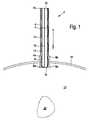
図1は、初期の第1の動作状態における第1の好ましい実施形態に係る、人体または動物の体から臓器を除去するための装置2の概略縦断面図を示している。 FIG. 1 shows a schematic longitudinal section of a device 2 for removing organs from the human or animal body according to a first preferred embodiment in an initial first operating state.
装置2は、開放近位端4aと開放遠位端4bとを有する外管4と、開放近位端6aと開放遠位端6bとを有する内管6とを備える。図示した実施形態の例では、装置2は、開放近位端8aと開放遠位端8bとを含み、外管4の延長部を形成するスリーブ8をさらに含む。それは、その近位端4aを有する外管4がスリーブ8の遠位端8bに取り付けられているからである。外管4とスリーブ8の配置に対して、内管6は、対応する適切な支持またはガイド要素を提供しなければならないために、配置の長手方向に沿って移動可能に支持されている。しかしながら、それらは図には示されていない。一方では外管4の内側とスリーブ8との間で、他方では内管6の外側との間に環状の横断面を有する間隙が延びている。これは、図1に示されている最初の第1の動作状態では、管状ケーシング12を収容している。図示の実施形態の例では、装置2は、スリーブ8の近位端8aの領域に配置されたブレードを備える粉砕装置をさらに備える。図示の実施形態では、内管6の長手方向軸の周りに回転可能に配置された回転ブレードとして具体化されている。前記ブレードは回転軸16の端部に配置されており、その回転軸は内管6の長手方向軸と一致しており、図示されていないモータによって回転させられる。図1からさらに明らかなように、図示の実施形態の例における外管4、内管6およびスリーブ8は、互いに対して実質的に同心円状に配置されているので、それらの長手方向軸は実質的に一致している。 Device 2 comprises an
スリーブ8は、図1からも明らかなように、装置2を人体または動物の体20の皮膚18に挿入するのを助け、同時に装置2を臓器22の方向に固定して体20から取り外す。これにおいて、図1に示される最初の第1の動作状態において、装置2は既に体20の皮膚18上に配置されているか、またはスリーブ8を用いて体20の皮膚18内に挿入されている。それ以外はまだ機能的な動作状態にない。 The
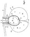
図2は、第2の動作状態にある装置2を示す。この状態では、内管6は外管4およびスリーブ8に対して矢印Aの方向に沿って移動している。それによって、管6はスリーブ8の近位端8aから引き出され、内管6の近位端6aが臓器22に当接するまで、除去されるべき臓器22の方向に体20内により深く挿入されている。しかしながら、その遠位端6bおよびそれに接続された部分を有する内管6は、外管4およびスリーブ8内に留まり続ける。その間、近位端6aに隣接した残りの部分を有する内管6は、スリーブ8から体20内に延び、その結果、この部分は体20内に露出される。同じことが管状ケーシング12にも当てはまり、これは、外管4およびスリーブ8の外への移動中に内管6に沿って取られる。その遠位端12bでは、それは、一方では外管4とスリーブ8との間の残りの間隙10内に、他方では内管6の遠位端6bに隣接する区域内で内管6との間に依然として位置する。しかしながら、他の全ての部分は露出しており、その移動中に内管6に沿って取られたその近位端12aは臓器22の隣に位置している。外管4の開放遠位端4bに接続されているのは、負圧装置、すなわち、図には示されていない吸引装置である。図2において“-p”として概略的に示される負圧を、外管4bのキャビティ4c内および内管6のキャビティ6c内に発生させるために、内管6の開放遠位端6bを介して外管4のキャビティ4cと連通している。内管6のキャビティ6c内の負圧が内管6の近位端6aに吸引作用を生じさせ、その結果として臓器22が内管6の近位端6a内に引き込まれる。このようにして、内管6の近位端6aと除去されるべき臓器22との間の最初のゆるい接触は、内管6の近位端6aで定位置に固定されている臓器22に変わる。 Figure 2 shows the device 2 in a second operating state. In this state, the
図2にさらに概略的に示されるように、例示された実施形態において、小穴26は管状ケーシング12の近位端12aに固定され、その端にループ28aを備えたワイヤまたは糸28が通され得る。図2は、小穴26およびループ28aを通って既に糸が通されている状態の糸28を示す。糸28は通常、装置の使用前に既に適切に準備されている。すなわち、それは、管状ケーシング12の近位端12aの小穴26を通して、そしてそれ自身の一端の一方に設けられたループ28aを通して、ゆるい状態で糸が通されるかまたは案内されている。したがって、図1の最初の第1の動作状態では、糸28は、小穴26およびループ28aと共に、一方の側で外管4とスリーブ8と他方の側で内管6との間の間隙10に、特に通常は、図1には示されていない外管4の近位端4aまたはスリーブ8の領域内に位置している。図2の装置2の第2の作動状態、つまり内管6の伸長状態では、糸28の作動は以下の通り、より詳細に説明され、様々な方法で実行され得る。例えば、糸28は、一方の側で外管4とスリーブ8との間に残っている間隙10を通して、および他方の側で内管の遠位端6bに隣接する内管6の部分を通して、内管6に沿って案内され、そしてその後、外管4のキャビティ4cを介して外側に制御され得る。しかしながら、代替的に、また、図には示されていないが、好ましくは既存の身体開口部を介して体20に挿入される内視鏡を用いて糸28を制御することも考えられる。さらに、上記の予め組み立てられた糸を通す代わりに糸28を小穴26およびループ28aを介して体20内でその後に案内することも少なくとも理論的には可能である。その場合、一般に、図には示されていない内視鏡の助けを借りてしか実施できない。 As shown more schematically in FIG. 2, in the illustrated embodiment,
また、完全を期すために、この時点で、装置2が図2に示すその第2の動作状態に達するときよりも早く、除去されるべき臓器22が分離され、したがって、体20内のその周囲から分離されるべきである。そのために、好ましくは、やはり図示されていない切断ブレードを有する内視鏡が使用される。 Also, for the sake of completeness, at this point the
図3は、第1の実施形態の装置2のさらなる詳細を示す。管状ケーシング12は、内側ケーシング12cと外側ケーシング12dとを有する二重ケーシングとして具体化されている。これにより、内側ケーシング12cと外側ケーシング12dとの間に間隙12eが形成される。図1~図3に示されている動作状態では、管状ケーシング12はその近位端12aで開いている。管状ケーシング12の近位端12aにおける内側ケーシング12cと外側ケーシング12dとの間の間隙12eは、内側ケーシング12cの近位端12caと外側ケーシング12dの近位端12daを、管状ケーシング12の近位端12aの全周を介して互いに接続することによって閉じられている。 FIG. 3 shows further details of the device 2 of the first embodiment.
さらに、図3は、装置2のさらなる構成要素として、把持アーム30の形態のハンドリング装置の少なくとも一部を示している。把持アーム30は、図示の実施形態の例では細長いロッド形状を有し、内管6の長手方向範囲に沿って整列している。把持アーム30は、間隙10内に配置されている。さらに、把持アーム30は、その長手方向の方向に沿って、一方では外管4およびスリーブ8に対して、そして他方では内管6に対して相対的に移動可能である。その目的のために、ハンドリング装置は、図には示されていない、対応する適切な支持および案内手段、ならびに、図には示されていない、アクチュエータおよび/またはハンドリングまたは駆動手段を備える。好ましくは、把持アーム30は、内管6の外側に支持され、内管6の長手方向に沿って移動可能である。その結果、スリーブ8からの内管6の伸長中に、図1に従い、装置2の最初の第1の動作状態から、図2に従い、装置2の第2の動作状態への移行中に、把持アーム30は、少なくとも最初は内管6に沿っている。しかしながら、代替的に、原則として、把持アーム30は、外管4の長手方向に沿って移動可能であるように外管4の内側に支持されることも考えられる。装置2の最初の第1の作動状態では、把持アーム30も一方では外管4とスリーブ8との間の他方では内側管6との間の空間内に収容されている。しかしながら、これは図1および図2では識別できない。 Furthermore, FIG. 3 shows at least part of a handling device in the form of a
さらに図3から明らかなように、把持アーム30は少なくとも内側ケーシング12cと外側ケーシング12との間でそれらの近位端30に隣接する部分に配置されている。そして、結果として、管状ケーシング12内の内側ケーシング12cと外側ケーシング12dとの間に形成された空間12e内にある。つまり、言い換えれば、二重ケーシングとして具体化された管状ケーシング12は、靴下のように把持アーム30を収容する。この目的のために、内側ケーシング12cは、好ましくはその近位端6aの領域で、内管6の外側に固定され、外側ケーシング12dは、スリーブ8または外管4の内側に固定される。これにより、一方では外管4とスリーブ8との間に、他方では内管6との間に形成された間隙10が、内側ケーシング12cと外側ケーシング12dとの間に形成された間隙12eと連通する。このような構成は、この実施形態において、管状ケーシング12が把持アーム30によって確実に案内されるようにする。そして、一方では外側管4とスリーブ8との間で、他方では内側管6との間の空間10から出ている間、図1および図2に示す矢印Aの方向に、スリーブ8からの内管6の伸長運動中だけではなく、内管6に対する管状ケーシング12の相対運動のためにも、特に、管状ケーシング12を内管6の近位端6aを越えて臓器22の除去される方向へと案内する。特に、実質的に図1および図2に示されている矢印Aの方向でも同様である。把持アーム30は、それらの長手方向に沿って移動可能であるだけではなく、図3にも示されているように、横方向に移動可能であり、すなわち、それらは広がることが可能である。図3からも明らかなように、除去されるべき臓器22は、通常内管6の直径よりも大きい。その結果、同期運動の間に、除去されるべき臓器22を囲むことができるようにするために、把持アーム30の外向きの広がり運動も必要とされる。この間、管状ケーシング12を臓器22の周りに配置する。この目的のために、把持アーム30は、図3に概略的に示されるように、枢動可能に相互接続された多数の要素からなる。および/または把持アーム30は、それらの長手方向の広がりに対して横方向に柔軟かつ弾性的に具体化されている。外側に広がる動きは、例えば、マイクロアクチュエータ、および/またはバネ、および/または、図に示されていない、形状および弾性の特別な相互作用によって発生させることが可能である。 3, the gripping
把持アーム30と内管6との間の相対運動は、把持アーム30の拡開運動中に内管6がスリーブ8に向かう方向に逆向きの運動を受けることを意図することによってさえも支援され得る。したがって、図3の矢印Bで示されるように、スリーブ8および外管4の中に引き込まれ始める。これにより、臓器22は、広げられた把持アーム30の間で疑似分娩されることになる。 The relative movement between the gripping
この一連の動きの間、元々広がっていた把持アーム30は、それらの近位端30aを互いに向かって動かすことによって除去されるべき臓器22を囲む。拡開運動とは反対のこの運動は、例えば、図に示されていない、上述のマイクロアクチュエータによって、または特殊な形状設計と弾力性の複合効果によって達成することができる。 During this sequence of motion, the originally spread grasping
図4に示されている方向すなわち矢印Cに沿ってそれぞれの対向する把持アーム30の近位端30aの移動が進むにつれて、把持アーム30は、除去されるべき臓器22を取り囲むので、この運動は閉鎖運動とも呼ぶことができる。この閉鎖運動により、把持アーム30は管状ケーシング12を臓器22の周囲に配置して除去される。これは、内管のキャビティ6c内の吸引効果のために、依然として内管6の近位端6aに取り付けられている。この第4の動作状態では、図4に示されるように、内管6の近位端6aがほぼスリーブ8の近位端8aの高さに位置する程度まで、内管6は再びスリーブ6内に引き込まれる。上述のように、取り付けられた臓器22を有する内管4の上方への移動は、把持アームの閉鎖運動および結果として生じる管状ケーシング12による臓器22の囲い込みを促進する。 As the movement of the proximal ends 30a of the respective opposing grasping
図3および図4の説明とは反対に、図3および図4を用いて説明した一連の動作中に、それらの近位端30aを有する把持アーム30は、通常、実質的に、二重ケーシングとして具体化された管状ケーシング12の閉じた近位端12aの内側と接触している。これはまた、把持アーム30を用いて管状ケーシング12をその近位端部12aの領域内に案内することを容易にする。これは、図5からも明らかである。 Contrary to the description of FIGS. 3 and 4, during the sequence of operations described with FIGS. is in contact with the inside of the closed
図3に係る装置2の第3の動作状態において、また図4に係る装置2の第4の動作状態において、上述した把持アーム30、ループ28aを通って案内される糸28、および管状ケーシング12の近位端12aに配置された小穴26の対応する一連の移動は、記載された移動シーケンス、特に管状ケーシング12による臓器22の囲い込みを妨げないために、非常に緩い状態のままである。 In the third operating state of the device 2 according to FIG. 3 and in the fourth operating state of the device 2 according to FIG. The corresponding series of movements of the
矢印Cの方向への把持アーム30の近位端30aの互いの方への移動の最後の部分は、糸28によって補助されるか、または、糸28を図4に示す矢印Dで示す方向に沿って引っ張り運動させることによって、糸28によってもっぱら引き継がれる。この結果として、管状ケーシング12は、装置2の第5の作動状態を示す図5に示されるように、その近位端12aで閉じることができる。したがって、管状ケーシング12は、その内側ケーシング12cによって囲まれ、除去されるべき臓器22を含む閉じたキャビティ12fを形成する。言い換えれば、管状ケーシング12は、除去されるべき臓器22を収容することができる小袋の形状を有する。 The final portion of the movement of the proximal ends 30a of the gripping
さらに、図5に示す装置2の第5の動作状態では、一方では外管4とスリーブ8との間で、他方では内管6との間の間隙10を通して加圧空気が注入され(図1)、間隙12eにも注入されている。これは、間隙10に隣接し、内側ケーシング12cと外側ケーシング12との間に配置されている。そのために、加圧空気源(図示せず)が外管4の遠位端4bの領域において間隙10に接続されている。この結果、内側ケーシング12cと外側ケーシング12dとの間の間隙12eが膨張し、それによって、この間隙12eに広がる過剰圧力が、図5および図6において符号“+p”によって示される。この過剰圧力は、一方では内側ケーシング12cを介して他方では外側ケーシング12dの膨張を介して除去されるべき臓器22への圧力をもたらす。 Furthermore, in a fifth operating state of the device 2 shown in FIG. 5, pressurized air is injected through the
内管6のキャビティ6c内に広がる負圧のために、処分されるべき臓器22は内管6の近位端6aに吸引されるだけでなく、後者の内側に引かれており、その間に回転ブレード14が矢印Eの方向に回転する有効範囲に達する。間隙12eの上流に広がる過剰圧力のために内側ケーシング12cを介した追加の加圧のために、除去されるべき臓器22は内管6の近位端6a内により強く押し込まれる。同時に臓器22は圧縮を受ける。この効果は、臓器22が回転ブレード14によって個々の小片に細かく砕かれることによって強化され、それは次いで内管6を通して吸い上げることがより容易になる。装置2のこの第6の動作状態が図6に示されており、これは例示目的のために、回転ブレード14によって臓器22から切断された内管6のキャビティ6c内の臓器22の片22aも示している。 Due to the negative pressure prevailing in the
除去されるべき臓器22が内管6の近位端6aでの吸引圧力の複合効果によって圧縮されたとき、過剰圧力は、管状ケーシング12の内側ケーシング12c、および回転ブレード14を介して、少なくともスリーブ8および隣接する外管4の内径よりも小さい幅まで臓器22に加えられ、残りの、こうして収縮した臓器22は、1つのさらなる操作工程において単一片として体20から取り外すことができる。装置2の対応する第7の動作状態が図7に示されている。この作動状態では、二重壁管状ケーシング12の内側ケーシング12cと外側ケーシング12との間の間隙12e内の過圧が遮断されるかまたは排除される。そして、この間隙12eは、外管4の遠位端4bの領域において、外管4と一方の側のスリーブとの間の他方の側の内管6との間の間隙10を介して通気される。その結果、内側ケーシング12cと外側ケーシング12の両方が弛緩状態に入る。内側ケーシング12cが残りの臓器22を収容する小袋の機能を果たし続ける間、よって、残りの臓器22の重量によって負荷をかけ続けると、図7に示すように、外側ケーシング12dは完全に負荷がなくなり、したがって緩んで弛緩した状態になる。 When the
原則として、臓器22は、収縮した状態でも、図7に示すように、回転ブレード14によってさらに細かく砕くことができると考えられる。そして、その後、個々の部分が内管6のキャビティ6cを介して吸引される。しかしながら、図7に示されている第7の作動状態では、回転ブレード14によるさらなる粉砕が行われない。その代わりに、残りの臓器22がその近位端6aに依然として固定された状態で内管6が今度は図7に示される矢印Eの方向に沿って、すなわち完全に体20から出てスリーブ8から外管に移動する。回転ブレード14による臓器のさらなる粉砕はもはや必要ではなくなったので、この内管6の後退移動中に、回転ブレード14を同時に保持する回転軸16が外管4の遠位端4bに向かう方向にスリーブ8から外へ移動することが意図されている。矢印Eに沿った回転軸16および内管6の移動も同期して起こり得る。さらに、この移動中、回転ブレード14はもはや作動していないので、回転軸16はその回転方向に沿って静止している、すなわちもはや回転を受けない。したがって、この実施形態では、回転ブレード14と回転軸16とを含む粉砕装置が設計されている。それは、回転ブレード14がスリーブ8の近位端8aの領域内に位置し、そしてこれにおいては、図1~図6に示されるように、依然として内管6の内側に配置されている、下方の動作位置と、外管の遠位端4bに向かう方向にスリーブ8から分離されている、上部休止位置との間に移動可能に配置されるようにする。それによって、それは依然として内管6内に位置していることが好ましい。関連する支持要素およびガイド要素ならびに場合によっては必要とされる駆動装置は、図には示されていない。 In principle, it is conceivable that the
図8は、第8の動作状態にある装置2を示しており、ここでは、再び回収された内管6を有する外管4が、第8の動作状態にある。管状ケーシング12内に収容されている臓器22は、まだ皮膚18内に残っているスリーブ8から引き抜かれている。続いて、残った臓器22を装置2から取り出し、先に切断した個々の構成要素22aと同じ方法で配置する(図6)。 FIG. 8 shows the device 2 in an eighth operating state, in which the
図9は、まだ閉じた状態のスリーブ8と把持アームの近位端30aのみを拡大した部分斜視図を概略的に示している。図1~図8の図とは対照的に、図9の図は、スリーブ8を体20の皮膚18に挿入する際に皮膚18上に載るようになる円周方向フランジ8cを依然として備えているスリーブ8を示しており、この方法では簡単であるがより効果的に、装置2を皮膚18上の定位置に固定するのを容易にする。 FIG. 9 schematically shows a partial perspective view enlarged only of the still closed
図10は、図9と実質的に同じ図を示し、図9とは対照的に、把持アームは、それらの近位端30aが閉じた状態で示されるだけでなく、それらが実質的に完全にスリーブ8内に引き込まれる位置でも示される。把持アーム30は除去されるべき臓器に向かってさらに延び、これは図10には示されておらず、既にわずかに開いている。 Figure 10 shows a view substantially the same as Figure 9, in contrast to which the gripping arms are not only shown closed at their
図11は、図9と実質的に同じ図を示すが、ここでは把持アーム30は実質的に完全に広げられており、それによってこれは図3に示される装置2の第3の動作状態にほぼ対応する。 FIG. 11 shows a view substantially the same as FIG. 9, but here the gripping
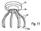
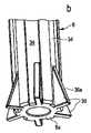
図12は、さらなる好ましい実施形態に係る、人体または動物の体から臓器を除去するための装置の一部としての内管6、スリーブ8、および把持アーム30のユニットの概略斜視図を示す。明瞭さのために、内管6のその近位端6aに隣接するその断面は、スリーブ8から体20の中へ突出しており、したがって露出されている部分のみが示されている。さらに、把持アーム30はハンドリング装置の一部を形成し、その残りは図示されていない。図9~図11に示す実施形態のように、図12の実施形態に示されているスリーブ8も、周方向フランジ8cを備える。 Figure 12 shows a schematic perspective view of a unit of
また、図12の実施形態では、把持アーム30は、それらの遠位端30bにおいて、環状連結要素32を介して互いに接続されている。その結果として、把持要素30は、内管6の長手方向に沿って一緒にかつ同期して動くことができる。したがって、環状連結要素32は、またハンドリング装置(図示されていないの残りの部分)の構成要素であり、好ましくは上述ハンドリング装置の他の構成要素を構成しているが図には示されていない、適切な駆動装置に結合されている。 Also, in the embodiment of FIG. 12, the gripping
さらに、図12の実施形態では、内管6の外側に、前者の長手方向に延びるガイド溝34が設けられ、その中に把持アーム30がガイド溝の長手方向に沿って移動可能に収容されている。 Furthermore, in the embodiment of FIG. 12, the outer side of the
最後に、把持アーム30は、スリーブ8の内側と内管6の外側との間に配置され、一方でスリーブ8の内側と他方で内管6の外側で実質的に接触している。 Finally, the
図12からさらに明らかなように、把持アーム30は弛緩状態で示されている。それぞれの対向する把持アーム30の近位端30aは、内管6の直径より小さい距離だけ離れている。さらに図12によれば、把持アーム30は、それらの近位端30aと遠位端30bとの間に、少なくともそれらの半径方向に沿って最も外側に位置するように、内側管に対して外側に湾曲した中央部分を含む。その範囲において、それぞれの対向する把持アーム30からの中央部分の距離は、内管6の直径よりも大きい。 As further apparent from Figure 12, the
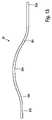
図12に示す把持アーム30のうち、単一の把持アーム30が側面図で図13に示されているので、把持アーム30の範囲および形状は、図13において容易に識別可能である。図13に示す実施形態の例では、把持アーム30は、その近位端30aに隣接して、第1の外向き湾曲した部分30c、その遠位端30bに隣接して、第2の外向きに湾曲した部分30dを備えている。それによって、2つの外側に湾曲した部分30c,30dは中央部分30eを介して接続されており、それは、今度は弓形形状で具体化されている。図13にさらに明らかなように、近位端30aと遠位端30bとは、互いにほぼ同一平面上に位置合わせされている。最後に、把持アーム30は弾性材料、好ましくはプラスチックからなる。 The extent and shape of the gripping
図12~図13に示す実施形態の例では、ハンドリング装置の後退した最終位置において、いわゆる初期位置にある把持アーム30は、一方では外管4とスリーブ8との間で、他方では内管6との間の間隙10内で実質的に完全に引き伸ばされた状態に強制的に運ばれ(図1)、よって、実質的に完全に拡張される。なぜなら、間隙10の半径方向の開口幅は、把持アーム30の半径方向の厚さよりもわずかに大きいだけであるからである。そして、一方では内管6の外側と他方では外管4の内側とスリーブ8との間に間隙10内に実質的な間隙がないからである。その結果、この状態は強制的な拘束と見ることもでき、これは上述の構成の結果であり、把持アーム30を他の選択のままにするのではなく、実質的に完全に伸びた形状をとることである。一旦ハンドリング装置が除去されるべき臓器22に向かって体20内に移動される(図1)。そして、その結果としてその近位最終位置に向かって、最初に第1の外側に湾曲した部分30cの形状は把持アームをそれらの近位端30aの領域で広げる。この広がり移動は、把持アーム30の中央部分30eがスリーブ8からその半径方向外側に最も遠い位置にある部分と共に現れるまで続く。その結果、図11に示されるように、この瞬間に把持アーム30は同様に広げられた位置をとるようになる。スリーブ8からの連続的な動きの間、遠位端30bの方向における中央部分30eと第2の湾曲部分30dとの間の把持アーム30の形状は、それらの近位端30aにおいて把持アーム30の新たな閉鎖を引き起こす。特に、把持アーム30の湾曲した中央部分30eがスリーブ8の外側に露出しているときより遅くなく、したがって、把持アーム30がもはやスリーブ8によって課されるいかなる制約をも受けない。その後、把持アーム30はほぼ図12に示す位置をとる。 12-13, in the retracted final position of the handling device, the
図14は、さらなる好ましい実施形態に係る、人体または動物の体から臓器を除去するための装置の一部としての把持アーム30を有するハンドリング装置の一部を概略斜視図で示す。図14aで明らかなように、ここに示す実施形態は、いわゆる拡散要素36が各ガイド溝34内の内管6の近位端部6aの領域に配置されている点で図12の実施形態と異なる。拡散要素36は三角形状を有し、その外側にガイド面36aを有し、ガイド面36aは関連するガイド溝34の底部から内管6の近位端6aに向かう方向に立ち上がっている。その結果、内管6の近位端6aにおける内管6の中心軸からの拡散要素36のガイド面36aの半径方向距離は、内管6の半径よりも大きい。把持アーム30がスリーブ8の外へ、そしてこのときガイド溝34に沿って移動する間、近位端30aを有する把持アーム30は、最初に拡散要素36のガイド面36aと軸受接触し、連続移動中に拡散要素36のガイド面36aに沿って外側に押される。その結果、拡散要素36は隣接する把持アーム30を広げる際にくさびまたは円錐のように作用する。 Figure 14 shows in schematic perspective view part of a handling device with a
図14でさらに明らかなように、拡散要素36は、把持アーム36の間隔に対応する距離で離間して配置されており、各把持アーム30は1つの拡散要素に関連付けられている。把持アーム30を拡散要素36から取り外すのを容易にするため、これまでは拡散要素を支えていた把持アーム30を、拡散要素36の隣の横方向位置へと通過させるために、一方では内管6および/または他方では把持アーム30を相対運動によって互いに衝突させることができる。その結果、把持アーム30に対する内管6の横方向変位、または把持アーム30をそれらの遠位端30bで接続するリング32に回転運動を加えることによる把持アーム30の横方向変位、または、内管6と把持アーム30との互いに対する横方向の相対変位によって、把持アーム30は拡散要素から滑り落ち、把持アーム30を閉じる。特に、図14bに詳細に示されるように、拡散要素36は、ガイド溝34の幅よりも小さい幅で具体化されてもよく、ガイド溝34内で横方向に配置されてもよい。その結果、把持アーム30が拡散要素36から滑り落ちた後、把持アーム30は再びガイド溝34によって受け入れられることができる。しかしながら、このために、把持アーム30の幅は、拡散要素36の領域内のガイド溝34の残りの内側幅よりも大きくなり得ないことが必要である。 14, the diffusing
Claims (36)
Translated fromJapanese近位端(6a)および遠位端(6b)を備え、その近位端(6a)で体(20)に部分的に挿入されるように意図された管(6)を有し、
管(6)を少なくとも部分的に取り囲み、管(6)に取り付けられる近位端(12a)および遠位端(12b)を有する管状ケーシング(12)を有し、
管状ケーシング(12)の近位端(12a)を閉じるように構成された閉鎖装置(26,28)を有し、
管(6)の遠位端(6b)は、吸引空気源に接続することができ、管(6)の近位端(6a)は、除去するべき臓器(22)と吸引係合するように構成され、
ハンドリング装置(30)は、管(6)に配置され、その近位端(12a)で管状ケーシング(12)を開くかまたは延ばし、臓器(22)の周りにそれを案内または配置するように構成され、前記ハンドリング装置(30)は、管(6)に対して配置され、伸長した近位端位置と後退した遠位端位置との間で後者の長手方向に沿って移動可能であり、
粉砕装置(14,16)は、管(6)内、好ましくはその近位端(6a)の領域に設けられることを特徴とする装置。A device for removing organs from the human or animal body, comprising:
having a tube (6) with a proximal end (6a) and a distal end (6b), intended at its proximal end (6a) to be partially inserted into the body (20),
having a tubular casing (12) at least partially surrounding a tube (6) and having a proximal end (12a) and a distal end (12b) attached to the tube (6);
a closure device (26, 28) configured to close the proximal end (12a) of the tubular casing (12);
The distal end (6b) of tube (6) may be connected to a source of suction air, and the proximal end (6a) of tube (6) is in suction engagement with the organ (22) to be removed. configured,
A handling device (30) is arranged in the tube (6) and configured to open or extend the tubular casing (12) at its proximal end (12a) and guide or position it around the organ (22). said handling device (30) being positioned relative to the tube (6) and movable between an extended proximal end position and a retracted distal end position along the longitudinal direction of the latter;
Device characterizedin that the comminution device (14, 16) is provided in the tube (6), preferably in the region of its proximal end (6a) .
Applications Claiming Priority (3)
| Application Number | Priority Date | Filing Date | Title |
|---|---|---|---|
| DE202016006899 | 2016-11-11 | ||
| DE202016006899.8 | 2016-11-11 | ||
| PCT/EP2017/079067WO2018087368A1 (en) | 2016-11-11 | 2017-11-13 | Device for removing organs from a human or animal body |
Publications (2)
| Publication Number | Publication Date |
|---|---|
| JP2019534109A JP2019534109A (en) | 2019-11-28 |
| JP7145852B2true JP7145852B2 (en) | 2022-10-03 |
Family
ID=60382195
Family Applications (1)
| Application Number | Title | Priority Date | Filing Date |
|---|---|---|---|
| JP2019525837AActiveJP7145852B2 (en) | 2016-11-11 | 2017-11-13 | A device for removing organs from the human or animal body |
Country Status (8)
| Country | Link |
|---|---|
| US (1) | US11134930B2 (en) |
| EP (1) | EP3537987B1 (en) |
| JP (1) | JP7145852B2 (en) |
| CN (1) | CN110213995B (en) |
| CA (1) | CA3045942A1 (en) |
| ES (1) | ES2836449T3 (en) |
| HU (1) | HUE052920T2 (en) |
| WO (1) | WO2018087368A1 (en) |
Families Citing this family (1)
| Publication number | Priority date | Publication date | Assignee | Title |
|---|---|---|---|---|
| JP7145852B2 (en)* | 2016-11-11 | 2022-10-03 | ベルント・ビュッシャーホフ | A device for removing organs from the human or animal body |
Citations (1)
| Publication number | Priority date | Publication date | Assignee | Title |
|---|---|---|---|---|
| JP2007325925A (en) | 2006-06-08 | 2007-12-20 | Olympus Medical Systems Corp | Stone crusher |
Family Cites Families (40)
| Publication number | Priority date | Publication date | Assignee | Title |
|---|---|---|---|---|
| US5556376A (en) | 1988-07-22 | 1996-09-17 | Yoon; Inbae | Multifunctional devices having loop configured portions and collection systems for endoscopic surgical procedures and methods thereof |
| US5176687A (en)* | 1991-05-10 | 1993-01-05 | Hasson Harrith M | Disposable pouch container for isolation and retrieval of tissues removed at laparoscopy |
| US5215521A (en)* | 1991-11-26 | 1993-06-01 | Cochran James C | Laparoscopy organ retrieval apparatus and procedure |
| US5312417A (en)* | 1992-07-29 | 1994-05-17 | Wilk Peter J | Laparoscopic cannula assembly and associated method |
| US6168604B1 (en)* | 1995-10-06 | 2001-01-02 | Metamorphic Surgical Devices, Llc | Guide wire device for removing solid objects from body canals |
| US5779716A (en)* | 1995-10-06 | 1998-07-14 | Metamorphic Surgical Devices, Inc. | Device for removing solid objects from body canals, cavities and organs |
| DE19717790A1 (en)* | 1997-04-26 | 1998-10-29 | Convergenza Ag | Device with a therapeutic catheter |
| JP4255208B2 (en)* | 1997-07-24 | 2009-04-15 | レックス メディカル リミテッド パートナーシップ | Device for resecting subcutaneous target tissue mass |
| US6156055A (en)* | 1999-03-23 | 2000-12-05 | Nitinol Medical Technologies Inc. | Gripping device for implanting, repositioning or extracting an object within a body vessel |
| DE10229137A1 (en) | 2002-06-28 | 2004-01-29 | Ethicon Gmbh | Surgical instrument |
| US20040006355A1 (en)* | 2002-07-03 | 2004-01-08 | Rubicor Medical, Inc. | Methods and devices for cutting and collecting soft tissue |
| US7044956B2 (en)* | 2002-07-03 | 2006-05-16 | Rubicor Medical, Inc. | Methods and devices for cutting and collecting soft tissue |
| EP1603452B1 (en)* | 2003-03-17 | 2017-05-17 | Covidien LP | Endoscopic tissue removal apparatus |
| US7122011B2 (en)* | 2003-06-18 | 2006-10-17 | Rubicor Medical, Inc. | Methods and devices for cutting and collecting soft tissue |
| WO2008124618A1 (en)* | 2007-04-05 | 2008-10-16 | Nmt Medical, Inc. | Implant recovery device |
| US8348827B2 (en)* | 2007-06-12 | 2013-01-08 | Ethicon Endo-Surgery, Inc. | Specimen removal pouch |
| CN100486541C (en)* | 2007-06-25 | 2009-05-13 | 西安远鸿科技有限责任公司 | Invivo-lithotriptor electrode or fiberoptic positioner |
| US9827084B2 (en) | 2007-10-26 | 2017-11-28 | Embolitech, Llc | Intravascular guidewire filter system for pulmonary embolism protection and embolism removal or maceration |
| US8075510B2 (en)* | 2007-12-20 | 2011-12-13 | Vortex Medical, Inc. | Systems and methods for removing undesirable material within a circulatory system |
| US8172772B2 (en)* | 2008-12-11 | 2012-05-08 | Ethicon Endo-Surgery, Inc. | Specimen retrieval device |
| CH701695A1 (en) | 2009-08-27 | 2011-02-28 | Straub Medical Ag | Catheter with protection system for aspirating, fragmenting and out pumping of removable material from hollow bodies or vessels, in particular of the human or animal body. |
| DE102010024360A1 (en)* | 2010-06-18 | 2011-12-22 | Olympus Winter & Ibe Gmbh | Uretersteinsauginstrument with a shaft |
| US20120130392A1 (en)* | 2010-11-18 | 2012-05-24 | Mayo Foundation For Medical Education And Research | Necrosectomy assist device |
| EP2497524A1 (en)* | 2011-03-08 | 2012-09-12 | Sanovas, Inc. | Multi-balloon catheter for extravasated drug delivery |
| US9832980B2 (en)* | 2012-02-22 | 2017-12-05 | Carter J. Kovarik | Selectively bendable remote gripping tool |
| US10226266B2 (en)* | 2012-02-22 | 2019-03-12 | Carter J. Kovarik | Selectively bendable remote gripping tool |
| US9770252B2 (en)* | 2013-03-14 | 2017-09-26 | Boston Scientific Scimed, Inc. | Retrieval device and related methods of use |
| WO2014141226A1 (en) | 2013-03-15 | 2014-09-18 | National University Of Ireland | A device suitable for removing matter from inside the lumen and the wall of a body lumen |
| US9987031B2 (en)* | 2013-06-14 | 2018-06-05 | Covidien Lp | Specimen retrieval device including an integrated sliding grasper |
| WO2015118542A1 (en)* | 2014-02-07 | 2015-08-13 | Yoav Lengel | Tissue extraction devices and methods |
| US20150305757A1 (en)* | 2014-04-28 | 2015-10-29 | NatEmack Holding, LLC | Method and apparatus for enclosure and removal of calculi and foreign bodies |
| WO2015168249A1 (en)* | 2014-04-29 | 2015-11-05 | Board Of Regents Of The University Of Nebraska | Surgical snare device |
| CN107920718B (en)* | 2015-02-23 | 2019-12-17 | 阿特里柯雷股份有限公司 | medical equipment |
| US20160262763A1 (en)* | 2015-03-12 | 2016-09-15 | Covidien Lp | Ligation and specimen retrieval device |
| US9717515B1 (en)* | 2015-08-10 | 2017-08-01 | MW Support Services, LLC | Medical device for sleeve gastrectomy surgery |
| EP3344167B1 (en)* | 2015-09-04 | 2021-12-01 | The Trustees of The University of Pennsylvania | Systems for percutaneous removal of objects from an internal body space |
| CN108348319B (en)* | 2015-09-28 | 2020-03-10 | 斯瑞克公司 | Mechanical embolectomy device and method |
| JP7145852B2 (en)* | 2016-11-11 | 2022-10-03 | ベルント・ビュッシャーホフ | A device for removing organs from the human or animal body |
| US20180193050A1 (en)* | 2017-01-10 | 2018-07-12 | Empire Technology Development Llc | Diverticulum inverting device |
| US10849604B2 (en)* | 2018-01-05 | 2020-12-01 | Gyrus Medical Limited | Method of removing an appendix |
- 2017
- 2017-11-13JPJP2019525837Apatent/JP7145852B2/enactiveActive
- 2017-11-13EPEP17800489.1Apatent/EP3537987B1/enactiveActive
- 2017-11-13HUHUE17800489Apatent/HUE052920T2/enunknown
- 2017-11-13USUS16/349,022patent/US11134930B2/enactiveActive
- 2017-11-13ESES17800489Tpatent/ES2836449T3/enactiveActive
- 2017-11-13WOPCT/EP2017/079067patent/WO2018087368A1/ennot_activeCeased
- 2017-11-13CNCN201780070075.9Apatent/CN110213995B/enactiveActive
- 2017-11-13CACA3045942Apatent/CA3045942A1/enactivePending
Patent Citations (1)
| Publication number | Priority date | Publication date | Assignee | Title |
|---|---|---|---|---|
| JP2007325925A (en) | 2006-06-08 | 2007-12-20 | Olympus Medical Systems Corp | Stone crusher |
Also Published As
| Publication number | Publication date |
|---|---|
| CN110213995A (en) | 2019-09-06 |
| CA3045942A1 (en) | 2018-05-17 |
| WO2018087368A1 (en) | 2018-05-17 |
| US20190261968A1 (en) | 2019-08-29 |
| EP3537987A1 (en) | 2019-09-18 |
| US11134930B2 (en) | 2021-10-05 |
| ES2836449T3 (en) | 2021-06-25 |
| EP3537987B1 (en) | 2020-09-16 |
| CN110213995B (en) | 2022-07-26 |
| JP2019534109A (en) | 2019-11-28 |
| HUE052920T2 (en) | 2021-05-28 |
Similar Documents
| Publication | Publication Date | Title |
|---|---|---|
| US6752822B2 (en) | Body tissue retrievel bag arrangement | |
| US9095328B2 (en) | Endoscopes having multiple lumens for tissue acquisition and removal and related methods of use | |
| US9375224B2 (en) | Device for removing tissue | |
| US11931293B2 (en) | Apparatus and method for cataract extraction | |
| CN100594005C (en) | Orifice introducer | |
| KR101893987B1 (en) | Laparoscopic Surgical Tissue Extraction Device | |
| EP3445260B1 (en) | Specimen retrieval system for use in endoscopic surgery | |
| JP7090094B2 (en) | Methods and devices for cutting the lens in the eye | |
| EP3461421B1 (en) | Specimen retrieval device | |
| US20210113378A1 (en) | Apparatus and method for cataract extraction | |
| CN108618829A (en) | A kind of device for removing calculus of intrahepatic duct | |
| JP7145852B2 (en) | A device for removing organs from the human or animal body | |
| JP2023539124A (en) | Systems and methods for cell collection and protection of collected cells | |
| JP5975257B2 (en) | Area securing instrument and endoscope provided with area securing instrument | |
| US20240032903A1 (en) | Device for medical specimen retrieval | |
| US20140343368A1 (en) | Apparatus and Method for removing a foreign object from a rectal cavity | |
| CN216675802U (en) | Specimen fetching bag | |
| KR102543906B1 (en) | Capture device for stent limb cover | |
| CN215651399U (en) | A mechanism for grasping bile duct stones | |
| HK40006350B (en) | Device for removal of organs from the human or animal body | |
| HK40006350A (en) | Device for removal of organs from the human or animal body | |
| CN115281936A (en) | An eye stabilization system for corneal transplantation | |
| CN119074079A (en) | A laparoscopic specimen removal device | |
| JP2017205162A (en) | Tissue collection device |
Legal Events
| Date | Code | Title | Description |
|---|---|---|---|
| A621 | Written request for application examination | Free format text:JAPANESE INTERMEDIATE CODE: A621 Effective date:20201112 | |
| A977 | Report on retrieval | Free format text:JAPANESE INTERMEDIATE CODE: A971007 Effective date:20210929 | |
| A131 | Notification of reasons for refusal | Free format text:JAPANESE INTERMEDIATE CODE: A131 Effective date:20211005 | |
| A601 | Written request for extension of time | Free format text:JAPANESE INTERMEDIATE CODE: A601 Effective date:20211224 | |
| A601 | Written request for extension of time | Free format text:JAPANESE INTERMEDIATE CODE: A601 Effective date:20220304 | |
| A521 | Request for written amendment filed | Free format text:JAPANESE INTERMEDIATE CODE: A523 Effective date:20220328 | |
| TRDD | Decision of grant or rejection written | ||
| A01 | Written decision to grant a patent or to grant a registration (utility model) | Free format text:JAPANESE INTERMEDIATE CODE: A01 Effective date:20220823 | |
| A61 | First payment of annual fees (during grant procedure) | Free format text:JAPANESE INTERMEDIATE CODE: A61 Effective date:20220920 | |
| R150 | Certificate of patent or registration of utility model | Ref document number:7145852 Country of ref document:JP Free format text:JAPANESE INTERMEDIATE CODE: R150 | |
| R250 | Receipt of annual fees | Free format text:JAPANESE INTERMEDIATE CODE: R250 |