JP7145775B2 - rotating machinery - Google Patents
rotating machineryDownload PDFInfo
- Publication number
- JP7145775B2 JP7145775B2JP2019015196AJP2019015196AJP7145775B2JP 7145775 B2JP7145775 B2JP 7145775B2JP 2019015196 AJP2019015196 AJP 2019015196AJP 2019015196 AJP2019015196 AJP 2019015196AJP 7145775 B2JP7145775 B2JP 7145775B2
- Authority
- JP
- Japan
- Prior art keywords
- flow direction
- steam
- rotor
- casing
- fluid flow
- Prior art date
- Legal status (The legal status is an assumption and is not a legal conclusion. Google has not performed a legal analysis and makes no representation as to the accuracy of the status listed.)
- Active
Links
- 239000012530fluidSubstances0.000claimsdescription81
- 238000011144upstream manufacturingMethods0.000claimsdescription66
- 230000002093peripheral effectEffects0.000claimsdescription63
- 238000007789sealingMethods0.000claimsdescription25
- 239000013598vectorSubstances0.000description6
- 230000007423decreaseEffects0.000description5
- 238000010586diagramMethods0.000description2
- 230000001133accelerationEffects0.000description1
- 230000003247decreasing effectEffects0.000description1
- 230000006866deteriorationEffects0.000description1
- 238000000034methodMethods0.000description1
- 238000000926separation methodMethods0.000description1
Images


Classifications
- F—MECHANICAL ENGINEERING; LIGHTING; HEATING; WEAPONS; BLASTING
- F01—MACHINES OR ENGINES IN GENERAL; ENGINE PLANTS IN GENERAL; STEAM ENGINES
- F01D—NON-POSITIVE DISPLACEMENT MACHINES OR ENGINES, e.g. STEAM TURBINES
- F01D11/00—Preventing or minimising internal leakage of working-fluid, e.g. between stages
- F01D11/08—Preventing or minimising internal leakage of working-fluid, e.g. between stages for sealing space between rotor blade tips and stator
- F—MECHANICAL ENGINEERING; LIGHTING; HEATING; WEAPONS; BLASTING
- F01—MACHINES OR ENGINES IN GENERAL; ENGINE PLANTS IN GENERAL; STEAM ENGINES
- F01D—NON-POSITIVE DISPLACEMENT MACHINES OR ENGINES, e.g. STEAM TURBINES
- F01D5/00—Blades; Blade-carrying members; Heating, heat-insulating, cooling or antivibration means on the blades or the members
- F01D5/12—Blades
- F01D5/22—Blade-to-blade connections, e.g. for damping vibrations
- F01D5/225—Blade-to-blade connections, e.g. for damping vibrations by shrouding
- F—MECHANICAL ENGINEERING; LIGHTING; HEATING; WEAPONS; BLASTING
- F02—COMBUSTION ENGINES; HOT-GAS OR COMBUSTION-PRODUCT ENGINE PLANTS
- F02C—GAS-TURBINE PLANTS; AIR INTAKES FOR JET-PROPULSION PLANTS; CONTROLLING FUEL SUPPLY IN AIR-BREATHING JET-PROPULSION PLANTS
- F02C7/00—Features, components parts, details or accessories, not provided for in, or of interest apart form groups F02C1/00 - F02C6/00; Air intakes for jet-propulsion plants
- F02C7/28—Arrangement of seals
- F—MECHANICAL ENGINEERING; LIGHTING; HEATING; WEAPONS; BLASTING
- F16—ENGINEERING ELEMENTS AND UNITS; GENERAL MEASURES FOR PRODUCING AND MAINTAINING EFFECTIVE FUNCTIONING OF MACHINES OR INSTALLATIONS; THERMAL INSULATION IN GENERAL
- F16J—PISTONS; CYLINDERS; SEALINGS
- F16J15/00—Sealings
- F16J15/44—Free-space packings
- F16J15/447—Labyrinth packings
- F16J15/4472—Labyrinth packings with axial path
- F—MECHANICAL ENGINEERING; LIGHTING; HEATING; WEAPONS; BLASTING
- F01—MACHINES OR ENGINES IN GENERAL; ENGINE PLANTS IN GENERAL; STEAM ENGINES
- F01D—NON-POSITIVE DISPLACEMENT MACHINES OR ENGINES, e.g. STEAM TURBINES
- F01D11/00—Preventing or minimising internal leakage of working-fluid, e.g. between stages
- F01D11/02—Preventing or minimising internal leakage of working-fluid, e.g. between stages by non-contact sealings, e.g. of labyrinth type
- F—MECHANICAL ENGINEERING; LIGHTING; HEATING; WEAPONS; BLASTING
- F05—INDEXING SCHEMES RELATING TO ENGINES OR PUMPS IN VARIOUS SUBCLASSES OF CLASSES F01-F04
- F05D—INDEXING SCHEME FOR ASPECTS RELATING TO NON-POSITIVE-DISPLACEMENT MACHINES OR ENGINES, GAS-TURBINES OR JET-PROPULSION PLANTS
- F05D2220/00—Application
- F05D2220/30—Application in turbines
- F05D2220/31—Application in turbines in steam turbines
- F—MECHANICAL ENGINEERING; LIGHTING; HEATING; WEAPONS; BLASTING
- F05—INDEXING SCHEMES RELATING TO ENGINES OR PUMPS IN VARIOUS SUBCLASSES OF CLASSES F01-F04
- F05D—INDEXING SCHEME FOR ASPECTS RELATING TO NON-POSITIVE-DISPLACEMENT MACHINES OR ENGINES, GAS-TURBINES OR JET-PROPULSION PLANTS
- F05D2240/00—Components
- F05D2240/10—Stators
- F05D2240/12—Fluid guiding means, e.g. vanes
- F05D2240/126—Baffles or ribs
- F—MECHANICAL ENGINEERING; LIGHTING; HEATING; WEAPONS; BLASTING
- F05—INDEXING SCHEMES RELATING TO ENGINES OR PUMPS IN VARIOUS SUBCLASSES OF CLASSES F01-F04
- F05D—INDEXING SCHEME FOR ASPECTS RELATING TO NON-POSITIVE-DISPLACEMENT MACHINES OR ENGINES, GAS-TURBINES OR JET-PROPULSION PLANTS
- F05D2240/00—Components
- F05D2240/10—Stators
- F05D2240/12—Fluid guiding means, e.g. vanes
- F05D2240/127—Vortex generators, turbulators, or the like, for mixing
- F—MECHANICAL ENGINEERING; LIGHTING; HEATING; WEAPONS; BLASTING
- F05—INDEXING SCHEMES RELATING TO ENGINES OR PUMPS IN VARIOUS SUBCLASSES OF CLASSES F01-F04
- F05D—INDEXING SCHEME FOR ASPECTS RELATING TO NON-POSITIVE-DISPLACEMENT MACHINES OR ENGINES, GAS-TURBINES OR JET-PROPULSION PLANTS
- F05D2240/00—Components
- F05D2240/10—Stators
- F05D2240/12—Fluid guiding means, e.g. vanes
- F05D2240/129—Cascades, i.e. assemblies of similar profiles acting in parallel
- F—MECHANICAL ENGINEERING; LIGHTING; HEATING; WEAPONS; BLASTING
- F05—INDEXING SCHEMES RELATING TO ENGINES OR PUMPS IN VARIOUS SUBCLASSES OF CLASSES F01-F04
- F05D—INDEXING SCHEME FOR ASPECTS RELATING TO NON-POSITIVE-DISPLACEMENT MACHINES OR ENGINES, GAS-TURBINES OR JET-PROPULSION PLANTS
- F05D2240/00—Components
- F05D2240/55—Seals
- F—MECHANICAL ENGINEERING; LIGHTING; HEATING; WEAPONS; BLASTING
- F05—INDEXING SCHEMES RELATING TO ENGINES OR PUMPS IN VARIOUS SUBCLASSES OF CLASSES F01-F04
- F05D—INDEXING SCHEME FOR ASPECTS RELATING TO NON-POSITIVE-DISPLACEMENT MACHINES OR ENGINES, GAS-TURBINES OR JET-PROPULSION PLANTS
- F05D2250/00—Geometry
- F05D2250/20—Three-dimensional
- F05D2250/29—Three-dimensional machined; miscellaneous
- F05D2250/294—Three-dimensional machined; miscellaneous grooved
Landscapes
- Engineering & Computer Science (AREA)
- General Engineering & Computer Science (AREA)
- Mechanical Engineering (AREA)
- Chemical & Material Sciences (AREA)
- Combustion & Propulsion (AREA)
- Turbine Rotor Nozzle Sealing (AREA)
- Sealing Using Fluids, Sealing Without Contact, And Removal Of Oil (AREA)
Description
Translated fromJapanese本発明は、静止側と回転側との間に流体の漏えいを抑制するシール装置が配置される回転機械に関するものである。 BACKGROUND OF THE INVENTION 1. Field of the Invention The present invention relates to a rotary machine in which a seal device for suppressing fluid leakage is arranged between a stationary side and a rotating side.
例えば、蒸気タービンは、ケーシング内にロータが軸受により回転自在に支持され、ロータに複数段の動翼が固定される一方、ケーシングに複数段の静翼が複数段の動翼の間に位置するように固定されて構成される。そして、蒸気がケーシングの供給口から供給されると、蒸気が複数の動翼と静翼を通過することで、複数段の動翼を介してロータが駆動回転し、排出口から外部に排出される。 For example, in a steam turbine, a rotor is rotatably supported in a casing by bearings, and a plurality of stages of moving blades are fixed to the rotor, while a plurality of stages of stationary blades are positioned in a casing between the plurality of stages of moving blades. It is fixed and configured as follows. When steam is supplied from the supply port of the casing, the steam passes through the plurality of moving blades and stationary blades, driving the rotor to rotate through the multiple stages of moving blades, and is discharged to the outside from the discharge port. be.
このような蒸気タービンでは、ケーシングと動翼の先端部との間における蒸気の軸方向の漏れ流れを抑制するため、動翼の先端部とケーシングとの間にシール装置が設けられる。このシール装置は、一般的に、ラビリンスシールが適用される。ラビリンスシールは、動翼の先端部やケーシングの内面に複数のシールフィンが設けられて構成される。複数のシールフィンとケーシングの内面や動翼の先端部との間に隙間を形成することで、各シールフィン前後の圧力比を小さくして漏れ流量の抑制を図っている。 In such a steam turbine, a sealing device is provided between the tip of the rotor blade and the casing in order to suppress axial leakage flow of steam between the casing and the tip of the rotor blade. A labyrinth seal is generally applied to this sealing device. A labyrinth seal is configured by providing a plurality of seal fins on the tip of a rotor blade and the inner surface of a casing. By forming a gap between the plurality of seal fins and the inner surface of the casing or the tip of the moving blade, the pressure ratio before and after each seal fin is reduced to suppress the leakage flow rate.
シール装置から漏れた蒸気の流れは、動翼や静翼を通過した蒸気の主流に合流する。動翼を通過した蒸気の主流は、ロータの軸方向に沿った流れであるが、動翼を通過せずにシール装置から漏れた蒸気の流れは、ケーシングの内周面からロータ側に向けて傾斜すると共に、静翼によりロータの周方向に旋回する流れである。この場合、蒸気の主流に対してシール装置からの漏れ蒸気の流れを滑らかに合流させることで、この合流部での混合損失を小さくして性能の低下を抑制することが重要である。このような技術として、例えば、下記特許文献1に記載されたものがある。 The flow of steam that has leaked from the seal device joins the main stream of steam that has passed through the moving blades and stationary blades. The main flow of steam that has passed through the moving blades is along the axial direction of the rotor, but the flow of steam that has leaked from the sealing device without passing through the moving blades flows from the inner peripheral surface of the casing toward the rotor side. It is a flow that is inclined and swirled in the circumferential direction of the rotor by stationary blades. In this case, it is important to smoothly merge the flow of steam leaking from the sealing device with the main stream of steam, thereby reducing the mixing loss at the confluence portion and suppressing the deterioration of the performance. As such a technique, for example, there is one described in Patent Document 1 below.
上述した特許文献1の軸流タービンは、シールフィンより下流側に旋回流調整室を設け、この旋回流調整ロータの軸方向および径方向に延在する複数の遮蔽板を固定したものである。そのため、動翼を通過せずにシール装置から漏れた周方向に旋回する蒸気の流れは、複数の遮蔽板により周方向の速度成分が減少することとなり、蒸気の主流に対してシール装置からの漏れ蒸気の流れを滑らかに合流させることができる。ところが、この従来の軸流タービンでは、遮蔽板がロータの軸方向および径方向に延在する板形状をなすものであることから、周方向に沿った蒸気の流れが遮蔽板に衝突したとき、遮蔽板の連結部に剥離渦が生じて圧力損失が発生するおそれがある。 The axial flow turbine of Patent Document 1 described above has a swirl flow adjustment chamber provided downstream of the seal fins, and a plurality of shield plates extending in the axial direction and radial direction of the swirl flow adjustment rotor are fixed. As a result, the circumferential velocity component of the circumferentially swirling steam flow that leaks from the seal device without passing through the moving blades is reduced by the plurality of shield plates, and the flow of steam from the seal device decreases with respect to the main stream of steam. The flow of leaking steam can be smoothly merged. However, in this conventional axial flow turbine, the shielding plate has a plate shape extending in the axial direction and radial direction of the rotor. A separation vortex may be generated at the connecting portion of the shield plate, which may cause pressure loss.
本発明は上述した課題を解決するものであり、流体の主流に対してシール装置からの漏れる流体を滑らかに合流させることで合流部での混合損失を低減して性能の向上を図る回転機械を提供することを目的とする。 SUMMARY OF THE INVENTION The present invention is intended to solve the above-described problems, and provides a rotating machine that improves performance by reducing mixing loss at the confluence portion by smoothly joining the fluid leaking from the seal device to the main flow of the fluid. intended to provide
上記の目的を達成するための本発明の回転機械は、中空形状をなすケーシングと、前記ケーシング内に回転自在に支持される回転体と、前記回転体の外周部に固定される動翼と、前記動翼に対して流体の流れ方向における下流側に配置されて前記ケーシングの内周部に固定される静翼と、前記ケーシングの内周部と前記動翼の先端部との間に配置されるシール装置と、前記ケーシングにおける前記シール装置より流体の流れ方向の下流側に前記回転体の周方向に沿って設けられる旋回流生成室と、前記旋回流生成室に前記回転体の径方向に沿うと共に前記回転体の周方向に所定間隔を空けて設けられる複数の案内部材と、を備え、前記旋回流生成室は、流体の流れ方向における下流側の壁面が、前記静翼の流体の流れ方向における上流側の縁部より流体の流れ方向における下流側に位置する、ことを特徴とするものである。 A rotating machine according to the present invention for achieving the above object comprises a casing having a hollow shape, a rotating body rotatably supported in the casing, rotor blades fixed to an outer peripheral portion of the rotating body, a stationary blade arranged downstream of the rotor blade in the flow direction of the fluid and fixed to the inner peripheral portion of the casing; a swirling flow generating chamber provided along the circumferential direction of the rotating body downstream of the sealing device in the fluid flow direction in the casing; and a swirling flow generating chamber extending radially of the rotating body. a plurality of guide members along the rotating body and provided at predetermined intervals in the circumferential direction of the rotating body; It is characterized by being positioned downstream in the direction of fluid flow from the edge on the upstream side in the direction.
従って、流体がケーシングの内部に供給されると、流体の主流が静翼と動翼を通過することで動翼が回転する一方、流体の一部が静翼を通過した後にケーシングと動翼の先端部との間に流れるが、シール装置が機能して流体の漏れが抑制される。このとき、シール装置は、一部の流体が漏れ、この漏れ流体が旋回流生成室で旋回した後に静翼と動翼を通過した流体の主流に合流する。シール装置から漏れた漏れ流体は、静翼を通過するものの動翼を通過していないことから周方向の速度成分を有する。ここで、周方向の速度成分を有する漏れ流体は、旋回流生成室に流れ込んだときに複数の案内部材に案内されることで周方向の速度成分が減少される。そして、周方向の速度成分が減少した漏れ流体は、旋回流生成室で旋回した後、旋回流生成室に流れ込む周方向の速度成分を有する漏れ流体に干渉して渦流が発生する。このとき、旋回流生成室が静翼の縁部より流体の流れ方向における下流側に位置することから、旋回流生成室の容積が大きくなり、発生した渦流を閉じ込めることができ、周方向の速度成分が減少した漏れ流体は、流体の主流に滑らかに合流する。その結果、流体の主流に対してシール装置から漏れた流体を滑らかに合流させることで、合流部での混合損失を低減して性能の向上を図ることができる。 Therefore, when the fluid is supplied to the inside of the casing, the main flow of the fluid passes through the stator vanes and the rotor blades, causing the rotor blades to rotate. The sealing device functions to suppress fluid leakage. At this time, a part of the fluid leaks from the seal device, and after this leaked fluid swirls in the swirling flow generating chamber, it joins the main stream of the fluid that has passed through the stationary blade and the moving blade. The leaked fluid that leaks from the sealing device passes through the stator blades but does not pass through the rotor blades, so it has a velocity component in the circumferential direction. Here, the leaked fluid having a velocity component in the circumferential direction is guided by a plurality of guide members when flowing into the swirling flow generating chamber, thereby reducing the velocity component in the circumferential direction. Then, the leaked fluid whose circumferential velocity component has decreased interferes with the leaked fluid having the circumferential velocity component that flows into the swirl flow generation chamber after swirling in the swirl flow generation chamber, thereby generating a swirl. At this time, since the swirling flow generating chamber is located downstream of the edge of the stationary blade in the fluid flow direction, the volume of the swirling flow generating chamber increases, the generated vortex can be confined, and the circumferential velocity increases. Leakage fluid with reduced composition smoothly joins the main stream of fluid. As a result, the fluid leaked from the sealing device is allowed to smoothly merge with the main flow of fluid, thereby reducing mixing loss at the confluence portion and improving performance.
本発明の回転機械では、前記旋回流生成室は、前記ケーシングの内周面と、前記ケーシングにおける前記シール装置に対して流体の流れ方向における下流側に対向する第1壁面と、前記ケーシングの内周面に対して前記回転体の径方向における内側に対向する第2壁面とを有し、複数の案内部材は、少なくとも前記ケーシングの内周面と前記第1壁面に固定され、前記壁面としての前記第1壁面は、前記静翼の流体の流れ方向における上流側の縁部より流体の流れ方向における下流側に位置することを特徴としている。 In the rotary machine of the present invention, the swirling flow generating chamber includes an inner peripheral surface of the casing, a first wall surface facing the sealing device in the casing downstream in the fluid flow direction, and an inner wall surface of the casing. It has a second wall surface facing inward in the radial direction of the rotating body with respect to the peripheral surface, and the plurality of guide members are fixed to at least the inner peripheral surface of the casing and the first wall surface, The first wall surface is characterized in that it is located downstream in the fluid flow direction from the upstream edge of the stationary blade in the fluid flow direction.
従って、案内部材が固定された第1壁面が静翼の流体の流れ方向における上流側の縁部より流体の流れ方向における下流側に位置することから、複数の案内部材により漏れ流体における周方向の速度成分を減少させることができると共に、旋回流生成室の容積を大きして発生した渦流を旋回流生成室に閉じ込めることができる。 Therefore, since the first wall surface to which the guide member is fixed is positioned downstream in the fluid flow direction from the upstream edge of the stationary blade in the fluid flow direction, the plurality of guide members allow the leakage fluid to flow in the circumferential direction. The velocity component can be reduced, and the generated vortex can be confined in the swirl flow generation chamber by increasing the volume of the swirl flow generation chamber.
本発明の回転機械では、前記ケーシングの内周面に凹部が形成され、前記動翼の先端部が前記凹部内に所定隙間をあけて配置され、前記旋回流生成室は、前記凹部における流体の流れ方向における下流側に設けられ、前記凹部の内周面と、前記凹部に設けられる前記第1壁面と、前記ケーシングの内周面から流体の流れ方向の上流側に延出する突起部に設けられる前記第2壁面とを有し、前記第1壁面は、前記静翼の流体の流れ方向における上流側の縁部より流体の流れ方向における下流側に位置することを特徴としている。 In the rotating machine of the present invention, a concave portion is formed in the inner peripheral surface of the casing, the tip portion of the moving blade is arranged in the concave portion with a predetermined gap, and the swirling flow generating chamber is configured to allow fluid flow in the concave portion. Provided on the downstream side in the flow direction, and provided on the inner peripheral surface of the recess, the first wall surface provided in the recess, and the projection extending upstream in the fluid flow direction from the inner peripheral surface of the casing. and the first wall surface is positioned downstream in the fluid flow direction from the edge of the stationary blade on the upstream side in the fluid flow direction.
従って、動翼の先端部が配置された凹部に旋回流生成室を設け、旋回流生成室を構成する第1壁面を静翼の流体の流れ方向における上流側の縁部より流体の流れ方向における下流側に位置させることから、旋回流生成室の容積を大きして発生した渦流を旋回流生成室に閉じ込めることができる。 Therefore, the swirling flow generating chamber is provided in the recess where the tip of the moving blade is arranged, and the first wall surface constituting the swirling flow generating chamber is positioned in the fluid flow direction from the upstream edge of the stationary blade in the fluid flow direction. Since it is positioned on the downstream side, the volume of the swirling flow generating chamber can be increased to confine the generated vortex in the swirling flow generating chamber.
本発明の回転機械では、前記突起部は、流体の流れ方向における上流側の端部が、前記案内部材の流体の流れ方向における上流側の端部より、流体の流れ方向における上流側に位置することを特徴としている。 In the rotary machine of the present invention, the upstream end of the protrusion in the fluid flow direction is positioned upstream in the fluid flow direction from the upstream end of the guide member in the fluid flow direction. It is characterized by
従って、突起部の端部を案内部材の端部より流体の流れ方向における上流側に位置させることから、旋回流生成室から流体の主流に合流する漏れ流体の出口を狭くすることで、旋回流生成室から排出される周方向の速度成分が減少した漏れ流体と、旋回流生成室に流れ込む周方向の速度成分を有する漏れ流体とが干渉して発生した渦流を旋回流生成室に容易に閉じ込めることができる。 Therefore, since the end of the protrusion is located upstream in the flow direction of the fluid from the end of the guide member, the outlet of the leaked fluid that joins the main flow of the fluid from the swirling flow generating chamber is narrowed, thereby generating the swirling flow. The vortex generated by the interference between the leaked fluid discharged from the generation chamber with a reduced circumferential velocity component and the leaked fluid flowing into the swirl flow generation chamber and having a circumferential velocity component is easily confined in the swirl flow generation chamber. be able to.
本発明の回転機械では、前記案内部材は、流体の流れ方向における上流側の端部が、前記突起部の流体の流れ方向における上流側の端部より、流体の流れ方向における上流側に位置することを特徴としている。 In the rotary machine of the present invention, the upstream end of the guide member in the fluid flow direction is positioned upstream in the fluid flow direction from the upstream end of the projection in the fluid flow direction. It is characterized by
従って、案内部材の端部を突起部の端部より流体の流れ方向における上流側に位置させることから、旋回流生成室に流れ込んだ漏れ流体は、複数の案内部材に案内されることで周方向の速度成分が減少されると共に、複数の案内部材との接触により摩耗が増加して強度が低下することとなり、旋回流生成室から排出される周方向の速度成分が減少した漏れ流体と、旋回流生成室に流れ込む周方向の速度成分を有する漏れ流体とが干渉することで発生する渦流を減少させることができる。 Therefore, since the end of the guide member is positioned upstream in the flow direction of the fluid from the end of the protrusion, the leaked fluid that has flowed into the swirling flow generating chamber is guided by the plurality of guide members and In addition, contact with a plurality of guide members causes wear to increase and strength to decrease. As a result, the leakage fluid discharged from the swirling flow generation chamber has a reduced velocity component in the circumferential direction, and the swirl It is possible to reduce eddy currents generated by interference with leakage fluid having a velocity component in the circumferential direction flowing into the flow generating chamber.
本発明の回転機械では、前記案内部材と前記第2壁面との間に前記回転体の周方向に連通する連通部が設けられることを特徴としている。 The rotary machine of the present invention is characterized in that a communicating portion communicating in the circumferential direction of the rotor is provided between the guide member and the second wall surface.
従って、案内部材と第2壁面との間に連通部を設けることから、旋回流生成室から排出される周方向の速度成分が減少した漏れ流体と、旋回流生成室に流れ込む周方向の速度成分を有する漏れ流体とが干渉して発生した渦流を旋回流生成室の連通部に閉じ込めて渦強度を低減することができる。 Therefore, since the communicating portion is provided between the guide member and the second wall surface, the leaked fluid discharged from the swirling flow generation chamber has a reduced circumferential velocity component, and the circumferential velocity component flowing into the swirling flow generation chamber is reduced. The vortex intensity can be reduced by confining the vortex generated by interference with the leaked fluid having a
本発明の回転機械では、前記連通部は、前記動翼の先端部より前記回転体の径方向における外側まで設けられることを特徴としている。 The rotary machine of the present invention is characterized in that the communicating portion is provided from the tip portion of the rotor blade to the outer side in the radial direction of the rotating body.
従って、連通部を動翼の先端部より外側まで設けることから、発生した渦流を旋回流生成室の連通部に適正に閉じ込めて渦強度を低減することができる。 Therefore, since the communication portion is provided to the outer side of the tip portion of the moving blade, the generated vortex can be properly confined in the communication portion of the swirling flow generating chamber to reduce the vortex strength.
本発明の回転機械では、前記動翼は、先端部にシュラウドが固定され、前記シュラウドは、流体の流れ方向の下流側に、前記連通部側へ延出する第1案内面が設けられることを特徴としている。 In the rotary machine of the present invention, a shroud is fixed to a tip portion of the rotor blade, and the shroud is provided with a first guide surface extending toward the communicating portion on a downstream side in a fluid flow direction. Characterized by
従って、動翼に固定されたシュラウドの下流側に連通部側へ延出する第1案内面を設けることから、シール装置からの漏れ流れを連通部に適正に案内することができる。 Therefore, since the first guide surface extending toward the communication portion is provided downstream of the shroud fixed to the rotor blade, the leakage flow from the seal device can be properly guided to the communication portion.
本発明の回転機械では、前記シュラウドは、流体の流れ方向の下流側に前記回転体の径方向における内側を向く第2案内面が設けられることを特徴としている。 In the rotary machine of the present invention, the shroud is provided with a second guide surface facing inward in the radial direction of the rotating body on the downstream side in the flow direction of the fluid.
従って、シュラウドの下流側に径方向における内側を向く第2案内面を設けることから、旋回流生成室から流体の主流に合流する漏れ流体を第2案内面により滑らかに主流に合流させることができる。 Therefore, since the second guide surface facing inward in the radial direction is provided on the downstream side of the shroud, the leaked fluid that joins the main flow of fluid from the swirling flow generating chamber can be smoothly joined to the main flow by the second guide surface. .
本発明の回転機械では、前記案内部材は、前記回転体の径方向における内側に位置する第1案内体と、前記回転体の径方向における外側に位置して前記第1案内体より前記流体の流れ方向における上流側に延出する第2案内体とを有することを特徴としている。 In the rotary machine of the present invention, the guide member includes a first guide body positioned radially inside the rotor and a guide member positioned radially outside the rotor so that the fluid flows more efficiently than the first guide body. and a second guide extending upstream in the flow direction.
従って、案内部材として、径方向における内側に位置する第1案内体と、径方向における外側に位置して第1案内体より上流側に延出する第2案内体とを設けることから、旋回流生成室に流れ込んだ漏れ流体は、複数の案内部材に案内される前に強度が低下した後、複数の第1案内体および第2案内体に案内されることで周方向の速度成分が減少されると共に、複数の第2案内体との接触により摩耗が増加して強度が低下することとなり、旋回流生成室から排出される周方向の速度成分が減少した漏れ流体と、旋回流生成室に流れ込む周方向の速度成分を有する漏れ流体とが干渉することで発生する渦流を減少させることができる。 Therefore, by providing the first guide body positioned radially inward and the second guide body positioned radially outward and extending upstream from the first guide body as guide members, the swirling flow can be The leaked fluid that has flowed into the generation chamber is reduced in strength before being guided by the plurality of guide members, and then guided by the plurality of first and second guide members to reduce the velocity component in the circumferential direction. At the same time, contact with the plurality of second guide bodies causes wear to increase and strength to decrease. It is possible to reduce eddy currents that are generated by interference with the leaking fluid that flows in and has a velocity component in the circumferential direction.
本発明の回転機械によれば、流体の主流に対してシール装置から漏れる流体を滑らかに合流させることで、合流部での混合損失を低減して性能の向上を図ることができる。 According to the rotary machine of the present invention, the fluid leaking from the seal device is allowed to smoothly merge with the main flow of the fluid, thereby reducing the mixing loss at the confluence portion and improving the performance.
以下に添付図面を参照して、本発明に係る回転機械の好適な実施形態を詳細に説明する。なお、この実施形態により本発明が限定されるものではなく、また、実施形態が複数ある場合には、各実施形態を組み合わせて構成するものも含むものである。 A preferred embodiment of a rotary machine according to the present invention will be described in detail below with reference to the accompanying drawings. It should be noted that the present invention is not limited by this embodiment, and when there are a plurality of embodiments, the present invention includes a combination of each embodiment.
[第1実施形態]
図4は、本実施形態の蒸気タービンを表す概略図である。なお、以下の説明にて、ロータの軸方向をA、ロータの径方向をR、ロータの周方向をCで表記する。[First embodiment]
FIG. 4 is a schematic diagram showing the steam turbine of this embodiment. In the following description, A is the axial direction of the rotor, R is the radial direction of the rotor, and C is the circumferential direction of the rotor.
本実施形態では、本発明の回転機械として、蒸気タービンを例に挙げて説明する。図4に示すように、蒸気タービン10は、ケーシング11と、ロータ(回転体)12と、静翼13と、動翼14と、シール装置15とを備える。 In this embodiment, a steam turbine will be described as an example of a rotary machine of the present invention. As shown in FIG. 4 , the
ケーシング11は、中空形状をなし、内部にロータ12が水平方向に沿って配置されている。ロータ12は、ケーシング11に設けられた軸受20により軸心Oを中心として回転自在に支持される。静翼13は、ケーシング11の内周部にロータ12の軸方向Aに所定間隔を空けて複数固定される。ロータ12は、外周部に軸方向Aに所定間隔を空けて複数のロータディスク21が固定されており、動翼14は、各ロータディスク21の外周部に複数固定される。各静翼13と各動翼14は、ロータ12の径方向Rに沿うと共に、ロータ12の周方向に所定間隔を空けて配置され、ロータ12の軸方向Aに沿って交互に配置される。 The
ケーシング11は、軸方向Aの一端部側に蒸気供給口22が設けられ、蒸気供給口22は、蒸気通路23を通して各静翼13および各動翼14が配置される翼列部24に連通される。この翼列部24は、排気室25を通して蒸気排出口26に連通される。 The
また、ロータ12は、軸方向Aの各端部とケーシング11との間にシール部材27が設けられる。各シール部材27は、各軸受20よりも内部側、つまり、静翼13および動翼14側に配置される。更に、動翼14における径方向Rの外側に位置する先端部と、ケーシング11の内周部との間にシール装置15が設けられる。 Further, the
そのため、蒸気Sが蒸気供給口22から蒸気通路23を通して翼列部24に供給されると、この蒸気Sが複数の静翼13および複数の動翼14を通過することで、各動翼14を介してロータ12が駆動回転し、このロータ12に連結された図示しない発電機を駆動する。その後、動翼14を駆動した蒸気Sは、排気室25を通して蒸気排出口26から排出される。 Therefore, when the steam S is supplied from the
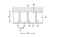
ここで、上述した蒸気タービン10におけるケーシング11と静翼13と動翼14とシール装置15との関係について詳細に説明する。図1は、第1実施形態の回転機械としての蒸気タービンにおける蒸気の流れを説明するための要部断面図、図2は、図1のII-II断面図、図3は、図1のIII-III断面図である。 Here, the relationship between the
図1から図3に示すように、シール装置15は、ケーシング11と動翼14の先端部との間に設けられる。シール装置15は、ケーシング11と動翼14の先端部との間をロータ12の軸方向Aに沿って高圧側Hから低圧側Lに流れる蒸気(流体)Sの流れの漏えいを抑制するものである。ここで、蒸気Sは、高圧側Hから低圧側Lに流れ、主流蒸気S1は、静翼13および動翼14を通過するように、蒸気流れ方向A1に沿って流れる。また、主流蒸気S1は、静翼13を通過した後、一部がケーシング11と動翼14の先端部との間のシール装置15に流れ、シール装置15からの漏れる漏れ蒸気S2が発生する。この漏れ蒸気S2は、静翼13を通過するものの、動翼14を通過していないことから、周方向Cの速度成分を有する。 As shown in FIGS. 1 to 3 , the sealing
すなわち、主流蒸気S1は、周方向Cの速度成分をほぼ持たない軸方向Aの流れであり、静翼13の前縁側に絶対速度ベクトルV1で流入する。主流蒸気S1は、静翼13の翼間を通過するときに増速および転向され、周方向Cの速度成分を持つ絶対速度ベクトルV2となり、静翼13の後縁側から流出する。静翼13から流出した蒸気Sは、大部分が動翼14に衝突することで、動翼14と共にロータ12を所定の回転速度で回転方向C1に回転させる。このとき、蒸気Sは、動翼14を通過するときに減速および転向され、周方向Cの速度成分をほぼ持たない軸方向Aに沿う絶対速度ベクトルV3となる。但し、主流蒸気S1が周方向Cの速度成分を持った流れの場合であっても、動翼14を回転させる作用は同様である。 That is, the mainstream steam S1 is a flow in the axial direction A that has almost no velocity component in the circumferential direction C, and flows into the leading edge side of the
一方、静翼13の翼間を通過した蒸気Sの絶対速度ベクトルV2は周方向Cの速度成分を持っており、動翼14を通過せずにシール装置15からの漏れた漏れ蒸気S2は、後述のシールフィンによる加減速や側壁やカバーの粘性摩擦により、速度は変化しているものの、周方向Cの速度成分を持つ流れである。そのため、漏れ蒸気S2が、周方向Cの速度成分をほぼ持たない絶対速度ベクトルV3の主流蒸気S1に合流するとき、合流部で混合損失が発生する。 On the other hand, the absolute velocity vector V2 of the steam S that has passed between the
なお、ここでは、主流蒸気S1が周方向Cの速度成分をほぼ持たない衝動タービンを対象にして説明したが、主流蒸気S1が周方向Cの速度成分を持つ反動タービンの場合であっても、主流蒸気S1と漏れ蒸気S2の方向ベクトルは異なるので、衝動タービンと同様に合流部で混合損失が発生する。本発明は、この反動タービンにも適用でき、また有効である。 Here, the description has been made with reference to the impulse turbine in which the mainstream steam S1 has almost no speed component in the circumferential direction C, but even in the case of the reaction turbine in which the mainstream steam S1 has a speed component in the circumferential direction C, Since the direction vectors of the mainstream steam S1 and the leak steam S2 are different, a mixing loss occurs at the confluence portion as in the impulse turbine. The present invention is also applicable and effective to this reaction turbine.
第1実施形態の蒸気タービン10は、旋回流生成室31と、複数の案内部材32とを備える。旋回流生成室31は、ケーシング11におけるシール装置15より蒸気流れ方向A1の下流側にロータ12の周方向Cに沿って設けられる。複数の案内部材32は、旋回流生成室31にロータ12の径方向Rに沿うと共に、ロータ12の周方向Cに所定間隔を空けて設けられる。 A
静翼13は、径方向Rの外側に位置する基端部がケーシング11の内周部に固定される一方、動翼14は、径方向Rの内側に位置する基端部がロータ12(図4参照)の外周部に固定される。動翼14は、軸方向Aに所定間隔を空けて配置される各静翼13の間に配置される。動翼14は、径方向Rの外側に位置する先端部にシュラウド41が設けられる。シール装置15は、ケーシング11の内周部と動翼14におけるシュラウド41の外周部との間に配置される。 The
ケーシング11は、シュラウド41の外周部に対向する内周面11aに凹部42が設けられる。凹部42は、ロータ12の周方向Cに沿って設けられる環状溝である。動翼14のシュラウド41は、ケーシング11の凹部42内に所定隙間をあけて配置される。シール装置15は、複数のシールフィン43,44,45を有する。シールフィン43,44は、基端部がケーシング11における凹部42の内周面42aに固定され、先端部が動翼14におけるシュラウド41の外周面41aに向けて延出される。シールフィン45は、シールフィン43,44の間に配置され、基端部が動翼14におけるシュラウド41の外周面41aに固定され、先端部がケーシング11における凹部42の内周面42aに向けて延出される。 The
シールフィン43,44,45は、ロータ12の軸方向Aに所定間隔を空けて設けられる。シールフィン43,44,45は、ロータ12の周方向Cに沿って設けられる。シールフィン43,44は、先端部とシュラウド41の外周面41aとの間に所定隙間が確保される。また、シールフィン45は、先端部と凹部42の内周面42aとの間に所定隙間が確保される。それぞれの所定隙間は、ほぼ同じ寸法に設定される。なお、シールフィン43,44,45の数や取付位置は、上述したものに限定されるものではない。 The
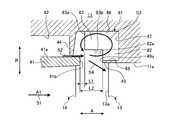
ケーシング11の凹部42は、軸方向Aの長さが動翼14のシュラウド41の軸方向Aの長さより長い。すなわち、凹部42は、動翼14の前縁よりも蒸気流れ方向A1の上流側から、動翼14の後縁よりも蒸気流れ方向A1の下流側まで設けられる。旋回流生成室31は、凹部42における動翼14の後縁よりも蒸気流れ方向A1の下流側に設けられる。旋回流生成室31は、ケーシング11(凹部42)の内周面46と、ケーシング11におけるシール装置15に対して蒸気流れ方向A1における下流側に対向する第1壁面47と、ケーシング11の内周面11aに対してロータ12(図4参照)の径方向Rにおける内側に対向する第2壁面48とを有する。ここで、旋回流生成室31は、蒸気流れ方向A1における下流側の第1壁面47が、静翼13の蒸気流れ方向A1における上流側の前縁部13aより蒸気流れ方向A1における下流側に位置する。 The
すなわち、内周面46は、凹部42の内周面42aより径方向Rの外側に位置し、周方向Cに沿って連続する。第1壁面47は、径方向Rに平行であると共に内周面46に直交する面であり、周方向Cに沿って連続する。第1壁面47は、旋回流生成室31よりロータ12における径方向Rの内側の内周面11aに固定された静翼13の前縁部13aより蒸気流れ方向A1における下流側に位置する。ケーシング11は、凹部42における蒸気流れ方向A1の下流側に、ケーシング11の内周面11aから蒸気流れ方向A1の上流側(凹部42側)に延出する突起部49が形成される。第2壁面48は、突起部49における径方向Rの外側に設けられると共に、内周面46に平行で第1壁面47に直交する面であり、周方向Cに沿って連続する。 That is, the inner
案内部材32は、ロータ12の径方向Rおよび軸方向Aに沿った板形状をなす。案内部材32は、内周面46と第1壁面47と第2壁面48に固定される。案内部材32の蒸気流れ方向A1における上流側の端部の位置と、突起部49の蒸気流れ方向A1における上流の端部の位置とは、軸方向Aにおいて同じ位置である。また、案内部材32は、蒸気流れ方向A1の上流側の端面32aがシールフィン44およびシュラウド41と軸方向Aにおいて所定距離だけ離間して配置される。 The
そのため、蒸気Sがケーシング11の内部に供給されて動翼14が回転するとき、蒸気Sは、高圧側Hから低圧側Lに蒸気流れ方向A1に沿って流れる。このとき、蒸気Sは、主流蒸気S1が静翼13および動翼14を通過するように流れ、一部が動翼14を通過することなく、ケーシング11と動翼14の先端部との間に設けられたシール装置15に流れる。このシール装置15は、蒸気Sの漏れを抑制するものの、一部が漏れて漏れ蒸気S2が発生する。シール装置15から漏れた漏れ蒸気S2は、旋回流生成室31で旋回した後に静翼13と動翼14を通過した主流蒸気S1に合流する。 Therefore, when the steam S is supplied to the inside of the
このとき、シール装置15から漏れた漏れ蒸気S2は、静翼13を通過するものの動翼14を通過していないことから、周方向Cの速度成分を有する。周方向Cの速度成分を有する漏れ蒸気S2は、旋回流生成室31内で周方向Cに沿う軸心を有する旋回流蒸気S3となる。すなわち、漏れ蒸気S2は、案内部材32案内されることで周方向Cの速度成分が減少された旋回流蒸気S3となる。そして、周方向Cの速度成分が減少して旋回流生成室31内を旋回した旋回流蒸気S3は、旋回流生成室31に流れ込む周方向Cの速度成分を有する漏れ蒸気S2に干渉して渦流が発生する。本実施形態では、旋回流生成室31が静翼13の前縁部13aより蒸気流れ方向A1における下流側に位置することから、旋回流生成室31の容積が大きくなっている。そのため、発生した渦流を旋回流生成室31内に閉じ込めることができ、周方向Cの速度成分が減少した漏れ蒸気S4は、シュラウド41と突起部49の間を通り、動翼14を通過した主流蒸気S1に滑らかに合流する。 At this time, the leaked steam S2 that has leaked from the
このように第1実施形態の回転機械にあっては、中空形状をなすケーシング11と、ケーシング11内に回転自在に支持されるロータ12と、ロータ12の外周部に固定される動翼14と、動翼14に対して蒸気流れ方向A1における下流側に配置されてケーシング11の内周部に固定される静翼13と、ケーシング11の内周部と動翼14の先端部との間に配置されるシール装置15と、ケーシング11におけるシール装置15より蒸気流れ方向A1の下流側にロータ12の周方向Cに沿って設けられる旋回流生成室31と、旋回流生成室31にロータ12の径方向Rに沿うと共にロータ12の周方向Cに所定間隔を空けて設けられる複数の案内部材32とを備え、旋回流生成室31は、蒸気流れ方向A1における下流側の第1壁面47が、静翼13の蒸気流れ方向A1における上流側の前縁部13aより蒸気流れ方向A1における下流側に位置する。 Thus, in the rotary machine of the first embodiment, the
従って、周方向Cの速度成分を有する漏れ蒸気S2は、旋回流生成室31に流れ込んだときに複数の案内部材32に案内されることで周方向Cの速度成分が減少される。そして、周方向Cの速度成分が減少して旋回流生成室31内を旋回した旋回流蒸気S3は、旋回流生成室31に流れ込む周方向Cの速度成分を有する漏れ蒸気S2に干渉して渦流が発生するが、この渦流を容積が大きくなった旋回流生成室31内に閉じ込めることができ、周方向Cの速度成分が減少した漏れ蒸気S4は、主流蒸気S1に滑らかに合流する。その結果、その結果、主流蒸気S1に対してシール装置15から漏れた蒸気Sを滑らかに合流させることで、合流部での混合損失を低減して性能の向上を図ることができる。 Therefore, the leaked steam S2 having a velocity component in the circumferential direction C is guided by the plurality of
第1実施形態本発明の回転機械では、旋回流生成室31は、凹部42の内周面46と、ケーシング11におけるシール装置15に対して蒸気流れ方向A1における下流側に対向する第1壁面47と、凹部42の内周面42aに対してロータ12の径方向Rにおける内側に対向する第2壁面48とを有し、複数の案内部材32を内周面46と第1壁面47に固定し、第1壁面47を静翼13の前縁部13aより下流側に位置させる。従って、複数の案内部材32により漏れ蒸気S2における周方向Cの速度成分を減少させることができると共に、旋回流生成室31の容積を大きして発生した渦流を旋回流生成室31に閉じ込めることができる。 First Embodiment In the rotary machine of the present invention, the swirling
第3実施形態の回転機械では、旋回流生成室31を凹部42における蒸気流れ方向A1における下流側に設け、凹部42の内周面46と、凹部42に設けられる第1壁面47と、ケーシング11の内周面11aから蒸気流れ方向A1の上流側に延出する突起部49に設けられる第2壁面48とを有し、第1壁面47を静翼13の前縁部13aより下流側に位置させる。従って、旋回流生成室31の容積を大きして発生した渦流を旋回流生成室31に閉じ込めることができる。 In the rotary machine of the third embodiment, the swirling
[第2実施形態]
図5は、第2実施形態の回転機械としての蒸気タービンにおける蒸気の流れを説明するための要部断面図である。なお、第2実施形態の基本的な構成は、上述した第1実施形態と同様であり、図1を用いて説明し、第1実施形態と同様の機能を有する部材には、同一の符号を付して詳細な説明は省略する。[Second embodiment]
FIG. 5 is a cross-sectional view of the essential part for explaining the flow of steam in the steam turbine as the rotary machine of the second embodiment. The basic configuration of the second embodiment is the same as that of the above-described first embodiment, and will be described with reference to FIG. , and detailed description thereof will be omitted.
第2実施形態において、図1および図5に示すように、蒸気タービン10は、ケーシング11と、ロータ12と、静翼13と、動翼14と、シール装置15と、旋回流生成室31と、複数の案内部材61とを備える。 In the second embodiment, as shown in FIGS. 1 and 5, a
旋回流生成室31は、ケーシング11におけるシール装置15より蒸気流れ方向A1の下流側にロータ12の周方向Cに沿って設けられる。複数の案内部材61は、旋回流生成室31にロータ12の径方向Rに沿うと共に、ロータ12の周方向Cに所定間隔を空けて設けられる。案内部材61は、内周面46と第1壁面47と第2壁面48に固定される。ここで、旋回流生成室31は、蒸気流れ方向A1における下流側の第1壁面47が、静翼13の蒸気流れ方向A1における上流側の前縁部13aより蒸気流れ方向A1における下流側に位置する。 The swirling
また、突起部49は、蒸気流れ方向A1における上流の端部の位置が、案内部材61の蒸気流れ方向A1における上流側の端部の位置より、蒸気流れ方向A1における上流側に位置する。すなわち、シュラウド41の後端面41bと案内部材61の蒸気流れ方向A1の上流側の端面61aとの距離L1は、シュラウド41の後端面41bと突起部49の蒸気流れ方向A1における上流の端面49aとの距離L2より長い。つまり、L1>L2である。 In addition, the upstream end of the
このように第2実施形態の回転機械では、突起部49は、蒸気流れ方向A1における上流側の端面49aが、案内部材61の蒸気流れ方向A1における上流側の端面61aより、蒸気流れ方向A1における上流側に位置している。 As described above, in the rotary machine of the second embodiment, the
従って、旋回流生成室31から主流蒸気S1に合流する漏れ蒸気S4の出口を狭くすることで、旋回流生成室31から排出される周方向Cの速度成分が減少した旋回流蒸気S3と、旋回流生成室31に流れ込む周方向Cの速度成分を有する漏れ蒸気S2とが干渉して発生した渦流を旋回流生成室31に容易に閉じ込めることができる。 Therefore, by narrowing the outlet of the leaked steam S4 that joins the main steam S1 from the swirl
[第3実施形態]
図6は、第3実施形態の回転機械としての蒸気タービンにおける蒸気の流れを説明するための要部断面図である。なお、第3実施形態の基本的な構成は、上述した第1実施形態と同様であり、図1を用いて説明し、第1実施形態と同様の機能を有する部材には、同一の符号を付して詳細な説明は省略する。[Third Embodiment]
FIG. 6 is a cross-sectional view of essential parts for explaining the flow of steam in a steam turbine as a rotary machine of the third embodiment. The basic configuration of the third embodiment is the same as that of the above-described first embodiment, and will be described with reference to FIG. , and detailed description thereof will be omitted.
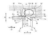
第3実施形態において、図1および図6に示すように、蒸気タービン10は、ケーシング11と、ロータ12と、静翼13と、動翼14と、シール装置15と、旋回流生成室31と、複数の案内部材71とを備える。 In the third embodiment, as shown in FIGS. 1 and 6, a
旋回流生成室31は、ケーシング11におけるシール装置15より蒸気流れ方向A1の下流側にロータ12の周方向Cに沿って設けられる。複数の案内部材71は、旋回流生成室31にロータ12の径方向Rに沿うと共に、ロータ12の周方向Cに所定間隔を空けて設けられる。案内部材71は、内周面46と第1壁面47に固定される。ここで、旋回流生成室31は、蒸気流れ方向A1における下流側の第1壁面47が、静翼13の蒸気流れ方向A1における上流側の前縁部13aより蒸気流れ方向A1における下流側に位置する。 The swirling
また、案内部材71は、蒸気流れ方向A1における上流側の端部が、突起部49の蒸気流れ方向A1における上流側の端部より、蒸気流れ方向A1における上流側に位置する。すなわち、シュラウド41の後端面41bと案内部材71の蒸気流れ方向A1の上流側の端面71aとの距離L1は、シュラウド41の後端面41bと突起部49の蒸気流れ方向A1における上流の端面49aとの距離L2より短い。つまり、L1<L2である。 Further, the upstream end of the
また、案内部材71と第2壁面48との間にロータ12の周方向に連通する連通部72が設けられる。つまり、案内部材71は、内周面46と第1壁面47とにだけ固定されており、第2壁面48に固定されずにここに連通部72が設けられる。この連通部72は、動翼14のシュラウド41における外周面41aよりロータ12の径方向Rにおける外側まで設けられる。 A
このように第3実施形態の回転機械では、案内部材71の蒸気流れ方向A1における上流側の端面71aが、突起部49における蒸気流れ方向A1における上流側の端面49aより、蒸気流れ方向A1における上流側に位置する。 As described above, in the rotary machine of the third embodiment, the
従って、旋回流生成室31に流れ込んだ漏れ蒸気S2は、複数の案内部材71に案内されることで周方向Cの速度成分が減少されると共に、複数の案内部材71との接触により摩耗が増加して強度が低下することとなる。そのため、旋回流生成室31から排出される周方向Cの速度成分が減少した旋回流蒸気S3と、旋回流生成室31に流れ込む周方向Cの速度成分を有する漏れ蒸気S2とが干渉することで発生する渦流を減少させることができる。 Therefore, the leaked steam S2 that has flowed into the swirling
第3実施形態の回転機械では、案内部材71と第2壁面48との間にロータ12の周方向Cに連通する連通部72を設ける。従って、旋回流生成室31から排出される周方向Cの速度成分が減少した旋回流蒸気S3と、旋回流生成室31に流れ込む周方向Cの速度成分を有する漏れ蒸気S2とが干渉することで発生する渦流を旋回流生成室31の連通部72に閉じ込めて渦強度を低減することができる。 In the rotary machine of the third embodiment, a communicating
第3実施形態の回転機械では、連通部72を動翼14のシュラウド41の外周面41aよりロータ12の径方向Rにおける外側まで設ける。従って、発生した渦流を旋回流生成室31の連通部72に適正に閉じ込めて渦強度を低減することができる。 In the rotary machine of the third embodiment, the
[第4実施形態]
図7は、第4実施形態の回転機械としての蒸気タービンにおける蒸気の流れを説明するための要部断面図である。なお、第4実施形態の基本的な構成は、上述した第1実施形態と同様であり、図1を用いて説明し、第1実施形態と同様の機能を有する部材には、同一の符号を付して詳細な説明は省略する。[Fourth Embodiment]
FIG. 7 is a cross-sectional view of essential parts for explaining the flow of steam in a steam turbine as a rotary machine of the fourth embodiment. The basic configuration of the fourth embodiment is the same as that of the first embodiment described above, and will be described with reference to FIG. , and detailed description thereof will be omitted.
第4実施形態において、図1および図7に示すように、蒸気タービン10は、ケーシング11と、ロータ12と、静翼13と、動翼14と、シール装置15と、旋回流生成室31と、複数の案内部材81とを備える。 In the fourth embodiment, as shown in FIGS. 1 and 7, a
旋回流生成室31は、ケーシング11におけるシール装置15より蒸気流れ方向A1の下流側にロータ12の周方向Cに沿って設けられる。複数の案内部材81は、旋回流生成室31にロータ12の径方向Rに沿うと共に、ロータ12の周方向Cに所定間隔を空けて設けられる。案内部材81は、内周面46と第1壁面47と第2壁面48に固定される。ここで、旋回流生成室31は、蒸気流れ方向A1における下流側の第1壁面47が、静翼13の蒸気流れ方向A1における上流側の前縁部13aより蒸気流れ方向A1における下流側に位置する。 The swirling
案内部材81は、ロータ12の径方向Rにおける内側に位置する第1案内体82と、ロータ12の径方向Rにおける外側に位置して第1案内体82より蒸気流れ方向A1における上流側に延出する第2案内体83とを有する。そして、突起部49は、蒸気流れ方向A1における上流の端部の位置が、第1案内体82の蒸気流れ方向A1における上流側の端部の位置と、軸方向Aにおいて同じ位置である。すなわち、シュラウド41の後端面41bと第2案内体83の蒸気流れ方向A1の上流側の端面83aとの距離L1は、シュラウド41の後端面41bと突起部49の蒸気流れ方向A1における上流の端面49aおよび第1案内体82の蒸気流れ方向A1における上流の端面82aとの距離L2より短い。つまり、L1<L2である。 The
このように第4実施形態の回転機械では、案内部材81は、ロータ12の径方向Rにおける内側に位置する第1案内体82と、ロータ12の径方向Rにおける外側に位置して第1案内体82より蒸気流れ方向A1における上流側に延出する第2案内体83とを有する。 As described above, in the rotary machine of the fourth embodiment, the
従って、旋回流生成室31に流れ込んだ漏れ蒸気S2は、複数の案内部材81に案内される前に強度が低下した後、複数の第1案内体82および第2案内体83に案内されることで周方向の速度成分が減少されると共に、複数の第2案内体83との接触により摩耗が増加して強度が低下することとなり、旋回流生成室31から排出される周方向Cの速度成分が減少した旋回流蒸気S3と、旋回流生成室31に流れ込む周方向Cの速度成分を有する漏れ蒸気S2とが干渉することで発生する渦流を減少させることができる。 Therefore, the leaked steam S2 that has flowed into the swirling
[第5実施形態]
図8は、第5実施形態の回転機械としての蒸気タービンにおける蒸気の流れを説明するための要部断面図である。なお、第5実施形態の基本的な構成は、上述した第1実施形態と同様であり、図1を用いて説明し、第1実施形態と同様の機能を有する部材には、同一の符号を付して詳細な説明は省略する。[Fifth embodiment]
FIG. 8 is a cross-sectional view of essential parts for explaining the flow of steam in a steam turbine as a rotary machine of the fifth embodiment. The basic configuration of the fifth embodiment is the same as that of the above-described first embodiment, and will be described with reference to FIG. , and detailed description thereof will be omitted.
第5実施形態において、図1および図8に示すように、蒸気タービン10は、ケーシング11と、ロータ12と、静翼13と、動翼14と、シール装置15と、旋回流生成室31と、複数の案内部材91とを備える。 In the fifth embodiment, as shown in FIGS. 1 and 8, a
旋回流生成室31は、ケーシング11におけるシール装置15より蒸気流れ方向A1の下流側にロータ12の周方向Cに沿って設けられる。複数の案内部材91は、旋回流生成室31にロータ12の径方向Rに沿うと共に、ロータ12の周方向Cに所定間隔を空けて設けられる。案内部材91は、内周面46と第1壁面47に固定される。ここで、旋回流生成室31は、蒸気流れ方向A1における下流側の第1壁面47が、静翼13の蒸気流れ方向A1における上流側の前縁部13aより蒸気流れ方向A1における下流側に位置する。 The swirling
また、案内部材91は、蒸気流れ方向A1における上流側の端部が、突起部49の蒸気流れ方向A1における上流側の端部より、蒸気流れ方向A1における上流側に位置する。そして、案内部材91と第2壁面48との間にロータ12の周方向に連通する連通部92が設けられる。つまり、案内部材91は、内周面46と第1壁面47とにだけ固定されており、第2壁面48に固定されずにここに連通部92が設けられる。この連通部92は、動翼14のシュラウド41における外周面41aよりロータ12の径方向Rにおける外側まで設けられる。 Further, the upstream end of the
更に、動翼14のシュラウド41は、蒸気流れ方向A1の下流側の外周面41aに、連通部92側へ延出する第1案内面93が設けられると共に、蒸気流れ方向A1の下流側にロータ12の径方向Rにおける内側を向く第2案内面94が設けられる。そして、シュラウド41の第1案内面93と案内部材91の蒸気流れ方向A1の上流側の端面91aとの距離L1は、シュラウド41の後端面41bと突起部49の蒸気流れ方向A1における上流の端面49aとの距離L2より短い。つまり、L1<L2である。 Further, the
このように第5実施形態の回転機械では、動翼14のシュラウド41は、蒸気流れ方向A1の下流側の外周面41aに、連通部92側へ延出する第1案内面93が設けられる。従って、シール装置15からの漏れ蒸気S2を連通部92に適正に案内することができる。 Thus, in the rotary machine of the fifth embodiment, the
第5実施形態の回転機械では、動翼14のシュラウド41は、蒸気流れ方向A1の下流側にロータ12の径方向Rにおける内側を向く第2案内面94が設けられる。従って、旋回流生成室31から主流蒸気S1に合流する旋回流蒸気S3を第2案内面94により滑らかに主流蒸気S1に合流させることができる。 In the rotary machine of the fifth embodiment, the
なお、上述した実施形態では、シール装置をラビリンスシールとしたが、別の非接触式シールでもよい。 In addition, in the above-described embodiment, the sealing device is a labyrinth seal, but another non-contact type seal may be used.
また、上述した実施形態では、本発明の回転機械を蒸気タービン10に適用したが、蒸気タービンに限らず、圧縮機や排気タービンなど、作動時に内部の圧力が外部の圧力より高くなる回転機械に適用することができる。 Further, in the above-described embodiment, the rotary machine of the present invention is applied to the
10 蒸気タービン(回転機械)
11 ケーシング
11a 内周面
12 ロータ
13 静翼
14 動翼
15 シール装置
20 軸受
21 ロータディスク
22 蒸気供給口
23 蒸気通路
24 翼列部
25 排気室
26 蒸気排出口
31 旋回流生成室
32,61,71,81,91 案内部材
32a,61a,71a,82a,83a,91a 端面
41 シュラウド
41a 外周面
41b 後端面
42 凹部
42a 内周面
43,44,45 シールフィン
46 内周面
47 第1壁面
48 第2壁面
49 突起部
49a 端面
72,92 連通部
82 第1案内体
83 第2案内体
93 第1案内面
94 第2案内面
A 軸方向
A1 蒸気流れ方向
C 周方向
C1 回転方向
R 径方向
S 蒸気
S1 主流蒸気
S2 漏れ蒸気
S3 旋回流蒸気
S4 漏れ蒸気10 steam turbine (rotating machine)
Claims (10)
Translated fromJapanese前記ケーシング内に回転自在に支持される回転体と、
前記回転体の外周部に固定される動翼と、
前記動翼に対して流体の流れ方向における下流側に配置されて前記ケーシングの内周部に固定される静翼と、
前記ケーシングの内周部と前記動翼の先端部との間に配置されるシール装置と、
前記ケーシングにおける前記シール装置より流体の流れ方向の下流側に前記回転体の周方向に沿って設けられる旋回流生成室と、
前記旋回流生成室に前記回転体の径方向に沿うと共に前記回転体の周方向に所定間隔を空けて設けられる複数の案内部材と、
を備え、
前記旋回流生成室は、流体の流れ方向における下流側の壁面が、前記静翼の流体の流れ方向における上流側の縁部より流体の流れ方向における下流側に位置する、
ことを特徴とする回転機械。a casing having a hollow shape;
a rotating body rotatably supported in the casing;
a moving blade fixed to the outer peripheral portion of the rotating body;
a stationary blade fixed to an inner peripheral portion of the casing disposed downstream of the rotor blade in the flow direction of the fluid;
a seal device disposed between an inner peripheral portion of the casing and a tip portion of the rotor blade;
a swirling flow generation chamber provided along the circumferential direction of the rotating body downstream of the seal device in the casing in the fluid flow direction;
a plurality of guide members provided in the swirling flow generating chamber along the radial direction of the rotor and at predetermined intervals in the circumferential direction of the rotor;
with
In the swirl flow generating chamber, a wall surface on the downstream side in the fluid flow direction is positioned downstream in the fluid flow direction from an edge portion on the upstream side in the fluid flow direction of the stationary blade.
A rotating machine characterized by:
Priority Applications (8)
| Application Number | Priority Date | Filing Date | Title |
|---|---|---|---|
| JP2019015196AJP7145775B2 (en) | 2019-01-31 | 2019-01-31 | rotating machinery |
| KR1020217022232AKR102579622B1 (en) | 2019-01-31 | 2019-11-13 | rotating machine |
| US17/422,391US11702947B2 (en) | 2019-01-31 | 2019-11-13 | Rotating machine |
| CN201980090015.2ACN113631797B (en) | 2019-01-31 | 2019-11-13 | rotating machinery |
| MX2021008565AMX2021008565A (en) | 2019-01-31 | 2019-11-13 | Rotary machine. |
| PCT/JP2019/044478WO2020158106A1 (en) | 2019-01-31 | 2019-11-13 | Rotary machine |
| PH1/2021/551655APH12021551655A1 (en) | 2019-01-31 | 2019-11-13 | Rotating machine |
| DE112019006786.9TDE112019006786T5 (en) | 2019-01-31 | 2019-11-13 | ROTARY MACHINE |
Applications Claiming Priority (1)
| Application Number | Priority Date | Filing Date | Title |
|---|---|---|---|
| JP2019015196AJP7145775B2 (en) | 2019-01-31 | 2019-01-31 | rotating machinery |
Publications (2)
| Publication Number | Publication Date |
|---|---|
| JP2020122446A JP2020122446A (en) | 2020-08-13 |
| JP7145775B2true JP7145775B2 (en) | 2022-10-03 |
Family
ID=71841984
Family Applications (1)
| Application Number | Title | Priority Date | Filing Date |
|---|---|---|---|
| JP2019015196AActiveJP7145775B2 (en) | 2019-01-31 | 2019-01-31 | rotating machinery |
Country Status (8)
| Country | Link |
|---|---|
| US (1) | US11702947B2 (en) |
| JP (1) | JP7145775B2 (en) |
| KR (1) | KR102579622B1 (en) |
| CN (1) | CN113631797B (en) |
| DE (1) | DE112019006786T5 (en) |
| MX (1) | MX2021008565A (en) |
| PH (1) | PH12021551655A1 (en) |
| WO (1) | WO2020158106A1 (en) |
Families Citing this family (3)
| Publication number | Priority date | Publication date | Assignee | Title |
|---|---|---|---|---|
| JP7145774B2 (en)* | 2019-01-31 | 2022-10-03 | 三菱重工業株式会社 | rotating machinery |
| JP7267022B2 (en)* | 2019-01-31 | 2023-05-01 | 三菱重工業株式会社 | rotating machinery |
| CN117449919B (en)* | 2023-12-12 | 2025-07-01 | 哈尔滨汽轮机厂有限责任公司 | Steam seal device of steam turbine and steam turbine |
Citations (3)
| Publication number | Priority date | Publication date | Assignee | Title |
|---|---|---|---|---|
| JP2007321721A (en) | 2006-06-05 | 2007-12-13 | Toshiba Corp | Axial turbine stage and axial turbine |
| EP2096262A1 (en) | 2008-02-26 | 2009-09-02 | Siemens Aktiengesellschaft | Axial flow turbine with low shroud leakage losses |
| JP2014234714A (en) | 2013-05-31 | 2014-12-15 | 三菱日立パワーシステムズ株式会社 | Axial flow turbine |
Family Cites Families (18)
| Publication number | Priority date | Publication date | Assignee | Title |
|---|---|---|---|---|
| JPS578302A (en)* | 1980-06-19 | 1982-01-16 | Hitachi Ltd | Internal stage structure of multistage axial-flow machine |
| JPS5985351U (en) | 1982-11-30 | 1984-06-09 | 日野自動車株式会社 | piston ring |
| DE3505491A1 (en)* | 1985-02-16 | 1986-08-21 | MTU Motoren- und Turbinen-Union München GmbH, 8000 München | GASKET FOR A FLUID MACHINE |
| JP2004011553A (en)* | 2002-06-07 | 2004-01-15 | Mitsubishi Heavy Ind Ltd | Axial flow type turbo machine |
| JP2009047043A (en)* | 2007-08-17 | 2009-03-05 | Mitsubishi Heavy Ind Ltd | Axial flow turbine |
| CN103985760B (en)* | 2009-12-25 | 2017-07-18 | 株式会社半导体能源研究所 | Semiconductor device |
| US8584469B2 (en)* | 2010-04-12 | 2013-11-19 | Siemens Energy, Inc. | Cooling fluid pre-swirl assembly for a gas turbine engine |
| JP5591042B2 (en)* | 2010-09-17 | 2014-09-17 | 三菱重工業株式会社 | Turbine |
| JP5567077B2 (en)* | 2012-08-23 | 2014-08-06 | 三菱重工業株式会社 | Rotating machine |
| JP5985351B2 (en) | 2012-10-25 | 2016-09-06 | 三菱日立パワーシステムズ株式会社 | Axial flow turbine |
| JP2014141912A (en)* | 2013-01-23 | 2014-08-07 | Mitsubishi Heavy Ind Ltd | Rotary machine |
| WO2014115706A1 (en)* | 2013-01-23 | 2014-07-31 | 三菱重工業株式会社 | Seal mechanism and rotating machine provided with seal mechanism |
| JP2015094220A (en)* | 2013-11-08 | 2015-05-18 | 三菱日立パワーシステムズ株式会社 | Axial flow turbine |
| US10830060B2 (en)* | 2016-12-02 | 2020-11-10 | General Electric Company | Engine component with flow enhancer |
| JP2018135847A (en)* | 2017-02-23 | 2018-08-30 | 三菱重工業株式会社 | Axial flow rotary machine |
| WO2018181855A1 (en)* | 2017-03-30 | 2018-10-04 | 三菱日立パワーシステムズ株式会社 | Steam turbine exhaust chamber, and steam turbine |
| US11149555B2 (en)* | 2017-06-14 | 2021-10-19 | General Electric Company | Turbine engine component with deflector |
| JP6783257B2 (en)* | 2018-01-31 | 2020-11-11 | 三菱重工業株式会社 | Axial rotating machine |
- 2019
- 2019-01-31JPJP2019015196Apatent/JP7145775B2/enactiveActive
- 2019-11-13WOPCT/JP2019/044478patent/WO2020158106A1/ennot_activeCeased
- 2019-11-13DEDE112019006786.9Tpatent/DE112019006786T5/enactivePending
- 2019-11-13USUS17/422,391patent/US11702947B2/enactiveActive
- 2019-11-13CNCN201980090015.2Apatent/CN113631797B/enactiveActive
- 2019-11-13MXMX2021008565Apatent/MX2021008565A/enunknown
- 2019-11-13PHPH1/2021/551655Apatent/PH12021551655A1/enunknown
- 2019-11-13KRKR1020217022232Apatent/KR102579622B1/enactiveActive
Patent Citations (3)
| Publication number | Priority date | Publication date | Assignee | Title |
|---|---|---|---|---|
| JP2007321721A (en) | 2006-06-05 | 2007-12-13 | Toshiba Corp | Axial turbine stage and axial turbine |
| EP2096262A1 (en) | 2008-02-26 | 2009-09-02 | Siemens Aktiengesellschaft | Axial flow turbine with low shroud leakage losses |
| JP2014234714A (en) | 2013-05-31 | 2014-12-15 | 三菱日立パワーシステムズ株式会社 | Axial flow turbine |
Also Published As
| Publication number | Publication date |
|---|---|
| MX2021008565A (en) | 2021-08-11 |
| CN113631797B (en) | 2023-01-20 |
| KR20210100726A (en) | 2021-08-17 |
| PH12021551655A1 (en) | 2022-05-16 |
| KR102579622B1 (en) | 2023-09-15 |
| JP2020122446A (en) | 2020-08-13 |
| US20220120188A1 (en) | 2022-04-21 |
| US11702947B2 (en) | 2023-07-18 |
| CN113631797A (en) | 2021-11-09 |
| WO2020158106A1 (en) | 2020-08-06 |
| DE112019006786T5 (en) | 2021-12-30 |
Similar Documents
| Publication | Publication Date | Title |
|---|---|---|
| CN105934615B (en) | Seal structure and rotating machinery | |
| JP7145775B2 (en) | rotating machinery | |
| US11136897B2 (en) | Seal device and turbomachine | |
| JP7145774B2 (en) | rotating machinery | |
| US11187097B2 (en) | Rotary machine | |
| CN103291379B (en) | Turbine | |
| JP7267022B2 (en) | rotating machinery | |
| CN108368744B (en) | Sealing fin, sealing structure and turbine machine | |
| JP6662661B2 (en) | Seal structure and turbo machinery | |
| JP6571257B2 (en) | Sealing device and turbomachine | |
| JP2015048771A (en) | Fluid machinery | |
| WO2019187330A1 (en) | Rotary machine | |
| TR2021011202T (en) | ROTATING MACHINE | |
| JP6638938B2 (en) | Rotating machinery | |
| JP2025526557A (en) | Turbine assembly for axial flow turbine and axial flow turbine | |
| JP2024127079A (en) | Seal devices and rotating machines | |
| JP2019100204A (en) | Turbine and rotor blade |
Legal Events
| Date | Code | Title | Description |
|---|---|---|---|
| A625 | Written request for application examination (by other person) | Free format text:JAPANESE INTERMEDIATE CODE: A625 Effective date:20210917 | |
| A711 | Notification of change in applicant | Free format text:JAPANESE INTERMEDIATE CODE: A712 Effective date:20220119 | |
| TRDD | Decision of grant or rejection written | ||
| A01 | Written decision to grant a patent or to grant a registration (utility model) | Free format text:JAPANESE INTERMEDIATE CODE: A01 Effective date:20220823 | |
| A61 | First payment of annual fees (during grant procedure) | Free format text:JAPANESE INTERMEDIATE CODE: A61 Effective date:20220920 | |
| R150 | Certificate of patent or registration of utility model | Ref document number:7145775 Country of ref document:JP Free format text:JAPANESE INTERMEDIATE CODE: R150 |