JP7143736B2 - Driving support device, wearable device, driving support method and program - Google Patents
Driving support device, wearable device, driving support method and programDownload PDFInfo
- Publication number
- JP7143736B2 JP7143736B2JP2018217670AJP2018217670AJP7143736B2JP 7143736 B2JP7143736 B2JP 7143736B2JP 2018217670 AJP2018217670 AJP 2018217670AJP 2018217670 AJP2018217670 AJP 2018217670AJP 7143736 B2JP7143736 B2JP 7143736B2
- Authority
- JP
- Japan
- Prior art keywords
- user
- vehicle
- wearable device
- determined
- recording function
- Prior art date
- Legal status (The legal status is an assumption and is not a legal conclusion. Google has not performed a legal analysis and makes no representation as to the accuracy of the status listed.)
- Active
Links
Images


Classifications
- H—ELECTRICITY
- H04—ELECTRIC COMMUNICATION TECHNIQUE
- H04B—TRANSMISSION
- H04B1/00—Details of transmission systems, not covered by a single one of groups H04B3/00 - H04B13/00; Details of transmission systems not characterised by the medium used for transmission
- H04B1/38—Transceivers, i.e. devices in which transmitter and receiver form a structural unit and in which at least one part is used for functions of transmitting and receiving
- H04B1/3827—Portable transceivers
- H04B1/385—Transceivers carried on the body, e.g. in helmets
- B—PERFORMING OPERATIONS; TRANSPORTING
- B60—VEHICLES IN GENERAL
- B60R—VEHICLES, VEHICLE FITTINGS, OR VEHICLE PARTS, NOT OTHERWISE PROVIDED FOR
- B60R16/00—Electric or fluid circuits specially adapted for vehicles and not otherwise provided for; Arrangement of elements of electric or fluid circuits specially adapted for vehicles and not otherwise provided for
- B60R16/02—Electric or fluid circuits specially adapted for vehicles and not otherwise provided for; Arrangement of elements of electric or fluid circuits specially adapted for vehicles and not otherwise provided for electric constitutive elements
- H—ELECTRICITY
- H04—ELECTRIC COMMUNICATION TECHNIQUE
- H04W—WIRELESS COMMUNICATION NETWORKS
- H04W4/00—Services specially adapted for wireless communication networks; Facilities therefor
- H04W4/02—Services making use of location information
- H04W4/023—Services making use of location information using mutual or relative location information between multiple location based services [LBS] targets or of distance thresholds
- G—PHYSICS
- G02—OPTICS
- G02B—OPTICAL ELEMENTS, SYSTEMS OR APPARATUS
- G02B27/00—Optical systems or apparatus not provided for by any of the groups G02B1/00 - G02B26/00, G02B30/00
- G02B27/01—Head-up displays
- G02B27/017—Head mounted
- G—PHYSICS
- G02—OPTICS
- G02B—OPTICAL ELEMENTS, SYSTEMS OR APPARATUS
- G02B27/00—Optical systems or apparatus not provided for by any of the groups G02B1/00 - G02B26/00, G02B30/00
- G02B27/01—Head-up displays
- G02B27/017—Head mounted
- G02B27/0172—Head mounted characterised by optical features
- G—PHYSICS
- G06—COMPUTING OR CALCULATING; COUNTING
- G06V—IMAGE OR VIDEO RECOGNITION OR UNDERSTANDING
- G06V20/00—Scenes; Scene-specific elements
- G06V20/50—Context or environment of the image
- G06V20/59—Context or environment of the image inside of a vehicle, e.g. relating to seat occupancy, driver state or inner lighting conditions
- G06V20/593—Recognising seat occupancy
- H—ELECTRICITY
- H04—ELECTRIC COMMUNICATION TECHNIQUE
- H04B—TRANSMISSION
- H04B17/00—Monitoring; Testing
- H04B17/20—Monitoring; Testing of receivers
- H04B17/27—Monitoring; Testing of receivers for locating or positioning the transmitter
- H—ELECTRICITY
- H04—ELECTRIC COMMUNICATION TECHNIQUE
- H04B—TRANSMISSION
- H04B17/00—Monitoring; Testing
- H04B17/30—Monitoring; Testing of propagation channels
- H04B17/309—Measuring or estimating channel quality parameters
- H04B17/318—Received signal strength
- H—ELECTRICITY
- H04—ELECTRIC COMMUNICATION TECHNIQUE
- H04N—PICTORIAL COMMUNICATION, e.g. TELEVISION
- H04N23/00—Cameras or camera modules comprising electronic image sensors; Control thereof
- H04N23/50—Constructional details
- H04N23/54—Mounting of pick-up tubes, electronic image sensors, deviation or focusing coils
- H—ELECTRICITY
- H04—ELECTRIC COMMUNICATION TECHNIQUE
- H04N—PICTORIAL COMMUNICATION, e.g. TELEVISION
- H04N23/00—Cameras or camera modules comprising electronic image sensors; Control thereof
- H04N23/57—Mechanical or electrical details of cameras or camera modules specially adapted for being embedded in other devices
- H—ELECTRICITY
- H04—ELECTRIC COMMUNICATION TECHNIQUE
- H04W—WIRELESS COMMUNICATION NETWORKS
- H04W4/00—Services specially adapted for wireless communication networks; Facilities therefor
- H04W4/30—Services specially adapted for particular environments, situations or purposes
- H04W4/40—Services specially adapted for particular environments, situations or purposes for vehicles, e.g. vehicle-to-pedestrians [V2P]
- H04W4/44—Services specially adapted for particular environments, situations or purposes for vehicles, e.g. vehicle-to-pedestrians [V2P] for communication between vehicles and infrastructures, e.g. vehicle-to-cloud [V2C] or vehicle-to-home [V2H]
- G—PHYSICS
- G02—OPTICS
- G02B—OPTICAL ELEMENTS, SYSTEMS OR APPARATUS
- G02B27/00—Optical systems or apparatus not provided for by any of the groups G02B1/00 - G02B26/00, G02B30/00
- G02B27/01—Head-up displays
- G02B27/0101—Head-up displays characterised by optical features
- G02B2027/0138—Head-up displays characterised by optical features comprising image capture systems, e.g. camera
- G—PHYSICS
- G02—OPTICS
- G02B—OPTICAL ELEMENTS, SYSTEMS OR APPARATUS
- G02B27/00—Optical systems or apparatus not provided for by any of the groups G02B1/00 - G02B26/00, G02B30/00
- G02B27/01—Head-up displays
- G02B27/0101—Head-up displays characterised by optical features
- G02B2027/014—Head-up displays characterised by optical features comprising information/image processing systems
- G—PHYSICS
- G02—OPTICS
- G02B—OPTICAL ELEMENTS, SYSTEMS OR APPARATUS
- G02B27/00—Optical systems or apparatus not provided for by any of the groups G02B1/00 - G02B26/00, G02B30/00
- G02B27/01—Head-up displays
- G02B27/017—Head mounted
- G02B2027/0178—Eyeglass type
- G—PHYSICS
- G02—OPTICS
- G02B—OPTICAL ELEMENTS, SYSTEMS OR APPARATUS
- G02B27/00—Optical systems or apparatus not provided for by any of the groups G02B1/00 - G02B26/00, G02B30/00
- G02B27/01—Head-up displays
- G02B27/0179—Display position adjusting means not related to the information to be displayed
- G02B2027/0187—Display position adjusting means not related to the information to be displayed slaved to motion of at least a part of the body of the user, e.g. head, eye
- H—ELECTRICITY
- H04—ELECTRIC COMMUNICATION TECHNIQUE
- H04B—TRANSMISSION
- H04B1/00—Details of transmission systems, not covered by a single one of groups H04B3/00 - H04B13/00; Details of transmission systems not characterised by the medium used for transmission
- H04B1/38—Transceivers, i.e. devices in which transmitter and receiver form a structural unit and in which at least one part is used for functions of transmitting and receiving
- H04B1/3827—Portable transceivers
- H04B1/385—Transceivers carried on the body, e.g. in helmets
- H04B2001/3866—Transceivers carried on the body, e.g. in helmets carried on the head
Landscapes
- Engineering & Computer Science (AREA)
- Physics & Mathematics (AREA)
- Signal Processing (AREA)
- Computer Networks & Wireless Communication (AREA)
- General Physics & Mathematics (AREA)
- Optics & Photonics (AREA)
- Electromagnetism (AREA)
- Multimedia (AREA)
- Quality & Reliability (AREA)
- Theoretical Computer Science (AREA)
- Mechanical Engineering (AREA)
- Traffic Control Systems (AREA)
- User Interface Of Digital Computer (AREA)
- Controls And Circuits For Display Device (AREA)
Description
Translated fromJapanese本発明は、運転支援装置、ウェアラブル装置、運転支援方法およびプログラムに関する。 TECHNICAL FIELD The present invention relates to a driving assistance device, a wearable device, a driving assistance method, and a program.
画像をメガネのレンズ上で結像することによってユーザに認識させるウェアラブル装置が知られている(例えば特許文献1参照)。このウェアラブル装置は、装着したユーザの周辺や他者等の被写体を撮像するカメラを備え、ユーザの装着時にカメラが連続的に撮像した映像を投影したり、ユーザの周辺の物体の検出に用いたりしている。 A wearable device is known that allows a user to recognize an image by forming an image on lenses of eyeglasses (see, for example, Patent Document 1). This wearable device is equipped with a camera that captures images of subjects such as the surroundings of the user wearing the device and others, and projects images continuously captured by the camera when the wearable device is worn by the user, and uses it to detect objects in the vicinity of the user. is doing.
ところで、ウェアラブル装置は、一般生活でも広く活用される可能性が極めて高く、ユーザが装着した状態で車両に乗車して運転することが考えられる。この場合、ウェアラブル装置は、取得した画像等を含む各種情報を、ネットワークを介して車両やサーバへ送信することで、車両やサーバから提供された新たなコンテンツやサービスを使用することができる。 By the way, wearable devices are very likely to be widely used in everyday life, and it is conceivable that users wear them while driving in vehicles. In this case, the wearable device can use new content and services provided by the vehicle or server by transmitting various information including acquired images to the vehicle or server via the network.
しかしながら、高速大容量通信の発展に伴って、ウェアラブル装置によって取得された各種情報は、ユーザが乗車する車両へ送信されたり、ネットワークを介してサーバへ送信したされたりすることで、装着したユーザや撮影された他者が意図しない形で使用されてしまう虞があった。このため、従来のウェアラブル装置では、装着したユーザや他者へのプライバシーに対して配慮した動作を行っていないという問題点があった。 However, with the development of high-speed large-capacity communication, various information acquired by the wearable device is transmitted to the vehicle in which the user rides, or is transmitted to the server via the network, so that the user wearing the wearable device There is a risk that the photographed person may be used in an unintended manner. For this reason, conventional wearable devices have a problem that they do not operate in consideration of the privacy of the user who wears them and other people.
本発明は、上記に鑑みてなされたものであって、装着したユーザや他者へのプライバシーに対して配慮した動作を行うことができる運転支援装置、ウェアラブル装置、運転支援方法およびプログラムを提供することを目的とする。 The present invention has been made in view of the above, and provides a driving support device, a wearable device, a driving support method, and a program that can perform operations in consideration of the privacy of the user wearing the device and others. for the purpose.
上述した課題を解決し、目的を達成するために、本発明に係る運転支援装置は、メモリと、ハードウェアを有するプロセッサと、を備え、前記プロセッサは、車両とユーザとの相対的な位置関係を示す乗車状況に基づいて、ユーザが装着するウェアラブル装置が有する機能であって、プライバシーに関わる情報を取得する機能の動作を切り替える制御を行う。 In order to solve the above-described problems and achieve the object, a driving assistance device according to the present invention includes a memory and a processor having hardware, the processor is configured to determine the relative positional relationship between the vehicle and the user. is a function of the wearable device worn by the user, and control is performed to switch the operation of the function of acquiring information related to privacy, based on the riding situation indicating .
また、前記プロセッサは、当該運転支援装置と前記ウェアラブル装置との距離が所定値以上であるか否かを判定し、前記距離が前記所定値以上であると判定した場合、前記ユーザが前記車両から降車した状態であると判定し、前記機能を停止する一方、前記距離が前記所定値以上でないと判定した場合、前記ユーザが前記車両に乗車した状態であると判定し、前記機能を開始してもよい。 Further, the processor determines whether or not a distance between the driving assistance device and the wearable device is equal to or greater than a predetermined value, and if the processor determines that the distance is equal to or greater than the predetermined value, the user moves away from the vehicle. It is determined that the user has gotten off the vehicle, and the function is stopped. On the other hand, if it is determined that the distance is not equal to or greater than the predetermined value, it is determined that the user is in the vehicle and the function is started. good too.
これによれば、ユーザがウェアラブル装置を装着したまま車両を降車した場合であっても、プロセッサがウェアラブル装置の機能であって、プライバシーに関わる情報を取得する機能を停止することで、ウェアラブル装置によって取得可能な情報がユーザや他者の意図しない形で使用されることを防止することができ、かつ、ユーザが車両に乗車した場合、プロセッサがウェアラブル装置の機能であって、プライバシーに関わる情報を取得する機能を開始することで、ウェアラブル装置によって取得された情報を用いた運転支援を行うことができる。 According to this, even if the user leaves the vehicle while wearing the wearable device, the processor stops the function of the wearable device to acquire information related to privacy. It is possible to prevent acquirable information from being used in a manner unintended by the user or others, and when the user gets into the vehicle, the processor is a function of the wearable device and protects the privacy-related information. Driving assistance using the information acquired by the wearable device can be performed by starting the acquisition function.
また、前記プロセッサは、前記車両のエンジンを始動するイグニッションスイッチがオフ状態または前記車両の電源を起動する起動スイッチがオフ状態であるか否かを判定し、前記イグニッションスイッチがオフ状態または前記起動スイッチがオフ状態である場合、前記ユーザが前記車両から降車した状態であると判定し、前記機能を停止する一方、前記イグニッションスイッチがオン状態および前記起動スイッチがオン状態である場合、前記ユーザが前記車両に乗車した状態であると判定し、前記機能を開始してもよい。 The processor determines whether an ignition switch for starting an engine of the vehicle is in an off state or a start switch for starting a power source of the vehicle is in an off state, and determines whether the ignition switch is in an off state or the start switch is in an off state. is off, it is determined that the user has exited the vehicle, and the function is stopped. It may be determined that the user is in the vehicle, and the function may be started.
これによれば、ユーザが車両の運転を終えてウェアラブル装置を装着したまま車両を降車した場合であっても、プロセッサがウェアラブル装置の機能であって、プライバシーに関わる情報を取得する機能を停止することで、ウェアラブル装置によって取得可能な情報がユーザや他者の意図しない形で使用されることを防止することができ、かつ、ユーザが車両に乗車して車両の運転を開始した場合、プロセッサがウェアラブル装置の機能であって、プライバシーに関わる情報を取得する機能を開始することで、ウェアラブル装置によって取得された情報を用いた運転支援を行うことができる。 According to this, even when the user finishes driving the vehicle and gets off the vehicle with the wearable device still attached, the processor stops the function of the wearable device, which is the function of acquiring information related to privacy. Thus, it is possible to prevent the information obtainable by the wearable device from being used in an unintended manner by the user or others, and when the user gets into the vehicle and starts driving the vehicle, the processor Driving assistance using the information acquired by the wearable device can be performed by starting a function of the wearable device that acquires information related to privacy.
また、前記プロセッサは、前記ウェアラブル装置から受信する信号の信号強度が所定値未満であるか否かを判定し、前記信号強度が前記所定値未満である場合、前記ユーザが前記車両から降車した状態であると判定し、前記機能を停止する一方、前記信号強度が前記所定値未満でない場合、前記ユーザが前記車両に乗車した状態であると判定し、前記機能を開始してもよい。 In addition, the processor determines whether or not the signal strength of the signal received from the wearable device is less than a predetermined value, and if the signal strength is less than the predetermined value, the user exits the vehicle. and the function is stopped, and if the signal strength is not less than the predetermined value, it may be determined that the user is in the vehicle and the function is started.
これによれば、ユーザがウェアラブル装置を装着したまま車両を降車した場合であっても、プロセッサがウェアラブル装置の機能であって、プライバシーに関わる情報を取得する機能を停止することで、ウェアラブル装置によって取得可能な情報がユーザや他者の意図しない形で使用されることを防止することができ、かつ、ユーザが車両に乗車した場合、プロセッサがウェアラブル装置の機能であって、プライバシーに関わる情報を取得する機能を開始することで、ウェアラブル装置によって取得された情報を用いた運転支援を行うことができる。 According to this, even if the user leaves the vehicle while wearing the wearable device, the processor stops the function of the wearable device to acquire information related to privacy. It is possible to prevent acquirable information from being used in a manner unintended by the user or others, and when the user gets into the vehicle, the processor is a function of the wearable device and protects the privacy-related information. Driving assistance using the information acquired by the wearable device can be performed by starting the acquisition function.
また、前記車両のドアの開閉状態を検出する開閉スイッチと、前記車両の運転席に対する着座の状態を検出するシートセンサと、をさらに備え、前記プロセッサは、前記開閉スイッチが検出した検出結果および前記シートセンサの検出結果に基づいて、前記乗車状況を判定し、前記ユーザが前記車両から降車した状態であると判定した場合、前記機能を停止する一方、前記ユーザが前記車両に乗車した状態であると判定した場合、前記機能を開始してもよい。 An open/close switch for detecting an open/closed state of a door of the vehicle, and a seat sensor for detecting a seating state with respect to a driver's seat of the vehicle. Based on the detection result of the seat sensor, the boarding condition is determined, and when it is determined that the user has exited the vehicle, the function is stopped while the user has boarded the vehicle. If so, the function may be initiated.
これによれば、ユーザが車両の運転を終えてウェアラブル装置を装着したまま車両を降車した場合であっても、プロセッサがウェアラブル装置の機能であって、プライバシーに関わる情報を取得する機能を停止することで、ウェアラブル装置によって取得可能な情報がユーザや他者の意図しない形で使用されることを防止することができ、かつ、ユーザが車両に乗車して車両の運転を開始した場合、プロセッサがウェアラブル装置の機能であって、プライバシーに関わる情報を取得する機能を開始することで、ウェアラブル装置によって取得された情報を用いた運転支援を行うことができる。 According to this, even when the user finishes driving the vehicle and gets off the vehicle with the wearable device still attached, the processor stops the function of the wearable device, which is the function of acquiring information related to privacy. Thus, it is possible to prevent the information obtainable by the wearable device from being used in an unintended manner by the user or others, and when the user gets into the vehicle and starts driving the vehicle, the processor Driving assistance using the information acquired by the wearable device can be performed by starting a function of the wearable device that acquires information related to privacy.
また、前記プロセッサは、前記車両および前記ウェアラブル装置を撮像した画像データに基づいて、前記乗車状況を判定し、前記ユーザが前記車両から降車した状態であると判定した場合、前記機能を停止する一方、前記ユーザが前記車両に乗車した状態であると判定した場合、前記機能を開始してもよい。 Further, the processor determines the boarding status based on image data obtained by imaging the vehicle and the wearable device, and stops the function when determining that the user has exited the vehicle. and when it is determined that the user is in the vehicle, the function may be started.
これによれば、ユーザがウェアラブル装置を装着したまま車両を降車した場合であっても、プロセッサがウェアラブル装置の機能であって、プライバシーに関わる情報を取得する機能を停止することで、ウェアラブル装置によって取得可能な情報がユーザや他者の意図しない形で使用されることを防止することができ、かつ、ユーザが車両に乗車した場合、プロセッサがウェアラブル装置の機能であって、プライバシーに関わる情報を取得する機能を開始することで、ウェアラブル装置によって取得された情報を用いた運転支援を行うことができる。 According to this, even if the user leaves the vehicle while wearing the wearable device, the processor stops the function of the wearable device to acquire information related to privacy. It is possible to prevent acquirable information from being used in a manner unintended by the user or others, and when the user gets into the vehicle, the processor is a function of the wearable device and protects the privacy-related information. Driving assistance using the information acquired by the wearable device can be performed by starting the acquisition function.
また、前記プロセッサは、前記ウェアラブル装置から送信された画像データに基づいて、前記乗車状況を判定し、前記ユーザが前記車両から降車した状態であると判定した場合、前記機能を停止する一方、前記ユーザが前記車両に乗車した状態であると判定した場合、前記機能を開始してもよい。 Further, the processor determines the boarding condition based on the image data transmitted from the wearable device, and when determining that the user has exited the vehicle, stops the function. The function may be initiated when it is determined that the user is in the vehicle.
これによれば、ユーザがウェアラブル装置を装着したまま車両を降車した場合であっても、プロセッサがウェアラブル装置の機能であって、プライバシーに関わる情報を取得する機能を停止することで、ウェアラブル装置によって取得可能な情報がユーザや他者の意図しない形で使用されることを防止することができ、かつ、ユーザが車両に乗車した場合、プロセッサがウェアラブル装置の機能であって、プライバシーに関わる情報を取得する機能を開始することで、ウェアラブル装置によって取得された情報を用いた運転支援を行うことができる。 According to this, even if the user leaves the vehicle while wearing the wearable device, the processor stops the function of the wearable device to acquire information related to privacy. It is possible to prevent acquirable information from being used in a manner unintended by the user or others, and when the user gets into the vehicle, the processor is a function of the wearable device and protects the privacy-related information. Driving assistance using the information acquired by the wearable device can be performed by starting the acquisition function.
また、前記ウェアラブル装置から送信された装着信号であって、前記ユーザが前記ウェアラブル装置の装着状態を示す装着信号に基づいて、前記ユーザが前記ウェアラブル装置を装着しているか否かを判定し、前記ユーザが前記車両に乗車した状態であると判定された場合において、前記ユーザが前記ウェアラブル装置を装着していない状態であると判定したとき、前記機能を停止する一方、前記ユーザが前記車両に乗車した状態であると判定された場合において、前記ユーザが前記ウェアラブル装置を装着している状態であると判定したとき、前記機能を開始してもよい。 determining whether or not the user is wearing the wearable device based on the wearing signal transmitted from the wearable device and indicating a wearing state of the wearable device by the user; When it is determined that the user is not wearing the wearable device when it is determined that the user is in the vehicle, the function is stopped while the user is in the vehicle. When it is determined that the user is wearing the wearable device, the function may be started.
これによれば、ユーザが車両に乗車した場合であっても、ユーザがウェアラブル装置を装着するまで、ウェアラブル装置による情報の取得を防止することができるので、ユーザや他者へのプライバシーに対して配慮した動作を行うことができる。 According to this, even when the user gets into the vehicle, it is possible to prevent the wearable device from acquiring information until the user wears the wearable device. Able to act with consideration.
また、前記プロセッサは、前記機能が停止されている場合において、前記機能の動作を開始する開始信号が入力されたとき、前記機能を開始してもよい。 Further, the processor may start the function when a start signal for starting the operation of the function is input when the function is stopped.
これによれば、ユーザが車両から降車している場合であっても、緊急時にウェアラブル装置によって各種情報を取得することができるので、証拠として用いることができる、または火事や天災等の突発的な状況を記録することができる。 According to this, even when the user gets out of the vehicle, various information can be acquired by the wearable device in an emergency, and can be used as evidence, or in the event of a sudden fire, natural disaster, or the like. You can record the situation.
また、前記ウェアラブル装置は、動画撮影可能な撮像部と、位置情報を取得するGPSセンサと、前記ユーザのバイタル情報を取得するバイタルセンサと、所定の位置に画像を投影する投影部と、を備え、前記機能は、前記撮像部による動画撮影機能、前記撮像部によって撮影された動画データを記録する記録機能、前記撮像部によって撮影された動画データ、前記GPSセンサが取得した前記位置情報および前記バイタルセンサが取得した前記バイタル情報のいずれか一つ以上を送信する送信機能、前記GPSセンサが前記位置情報を取得する取得機能および前記投影部が前記画像を投影する投影機能のいずれか一つ以上であってもよい。 Further, the wearable device includes an imaging unit capable of capturing moving images, a GPS sensor that acquires position information, a vital sensor that acquires vital information of the user, and a projection unit that projects an image at a predetermined position. , the functions include a moving image capturing function by the imaging unit, a recording function for recording moving image data captured by the imaging unit, moving image data captured by the imaging unit, the position information acquired by the GPS sensor, and the vital signs. any one or more of a transmission function of transmitting any one or more of the vital information acquired by the sensor, an acquisition function of the GPS sensor acquiring the position information, and a projection function of the projection unit projecting the image. There may be.
これによれば、ユーザの乗車状況に応じて、動画撮影機能、記録機能、送信機能および投影機能のいずれか一つ以上を制限するので、ユーザや他者へのプライバシーに対して配慮した動作を行うことができる。 According to this, one or more of the video shooting function, the recording function, the transmission function, and the projection function is restricted according to the user's boarding status, so that the operation can be performed in consideration of the privacy of the user and others. It can be carried out.
また、前記ウェアラブル装置は、所定の位置に画像を投影する投影部を備え、前記プロセッサは、前記乗車状況を判定し、前記ユーザが前記車両から降車した状態であると判定した場合、前記投影部が投影する前記画像を前記ユーザが歩行に適した表示内容に切り替える一方、前記ユーザが前記車両に乗車した状態であると判定した場合、前記投影部が投影する前記画像を、前記ユーザの運転を支援する表示内容に切り替えてもよい。 In addition, the wearable device includes a projection unit that projects an image at a predetermined position, and the processor determines the riding situation, and if the user is determined to have exited the vehicle, the projection unit While switching the image projected by the to display content suitable for the user to walk, if it is determined that the user is in the vehicle, the image projected by the projection unit is changed to display content suitable for the user's driving. You may switch to the display content to support.
これによれば、ユーザの乗車状況に応じて、ウェアラブル装置が投影する画像の表示内容を切り替えるので、ユーザの乗車状況に応じた表示を行うことができる。 According to this, since the display content of the image projected by the wearable device is switched according to the user's riding condition, the display can be performed according to the user's riding condition.
また、本発明に係るウェアラブル装置は、車両と双方向に通信可能であり、ユーザが装着するウェアラブル装置であって、前記車両と前記ユーザとの相対的な位置関係を示す乗車状況を受信する通信部と、ハードウェアを有するプロセッサと、を備え、前記プロセッサは、前記乗車状況に基づいて、当該ウェアラブル装置が有する機能であって、プライバシーに関わる情報を取得する機能の動作を切り替える制御を行う。 Further, a wearable device according to the present invention is capable of two-way communication with a vehicle, is worn by a user, and is a wearable device that receives a boarding situation indicating a relative positional relationship between the vehicle and the user. and a processor having hardware, wherein the processor controls switching of the operation of the function of acquiring information related to privacy, which is a function of the wearable device, based on the riding situation.
また、本発明に係る運転支援方法は、車両のユーザによる運転を支援する運転支援装置が実行する運転支援方法であって、前記車両と前記ユーザとの相対的な位置関係を示す乗車状況を取得し、メモリから読み出した前記乗車状況に基づいて、前記ユーザが装着するウェアラブル装置が有する機能であって、プライバシーに関わる情報を取得する機能の動作を切り替える制御を行う。 Further, a driving assistance method according to the present invention is a driving assistance method executed by a driving assistance device for assisting driving by a user of a vehicle, wherein a riding situation indicating a relative positional relationship between the vehicle and the user is acquired. Then, based on the riding condition read from the memory, control is performed to switch the operation of the function of the wearable device worn by the user, which is a function of acquiring information related to privacy.
また、本発明に係る運転支援方法は、車両と双方向に通信可能であり、ユーザが装着するウェアラブル装置が実行する運転支援方法であって、前記車両と前記ユーザとの相対的な位置関係を示す乗車状況を受信し、メモリから読み出した前記乗車状況に基づいて、当該ウェアラブル装置が有する機能であって、プライバシーに関わる情報を取得する機能の動作を切り替える制御を行う。 Further, a driving assistance method according to the present invention is a driving assistance method that is capable of two-way communication with a vehicle and executed by a wearable device worn by a user, wherein the relative positional relationship between the vehicle and the user is determined. It receives the indicated riding situation, and controls switching of the operation of the function of acquiring information related to privacy, which is a function of the wearable device, based on the riding situation read from the memory.
また、本発明に係るプログラムは、車両のユーザによる運転を支援する運転支援装置に実行させるプログラムであって、前記車両と前記ユーザとの相対的な位置関係を示す乗車状況を取得し、メモリから読み出した前記乗車状況に基づいて、前記ユーザが装着するウェアラブル装置が有する機能であって、プライバシーに関わる情報を取得する機能の動作を切り替える制御を行う。 Further, a program according to the present invention is a program to be executed by a driving assistance device for assisting driving of a vehicle by a user, acquiring a riding situation indicating a relative positional relationship between the vehicle and the user, Control is performed to switch the operation of the function of acquiring information related to privacy, which is a function of the wearable device worn by the user, based on the read riding condition.
また、本発明に係るプログラムは、車両と双方向に通信可能であり、ユーザが装着するウェアラブル装置が実行するプログラムであって、前記車両と前記ユーザとの相対的な位置関係を示す乗車状況を受信し、メモリから読み出した前記乗車状況に基づいて、当該ウェアラブル装置が有する機能であって、プライバシーに関わる情報を取得する機能の動作を切り替える制御を行う。 Further, a program according to the present invention is a program that is bidirectionally communicable with a vehicle and executed by a wearable device worn by a user, and which displays a riding situation indicating a relative positional relationship between the vehicle and the user. Based on the received ride status read out from the memory, control is performed to switch the operation of the function of acquiring information related to privacy, which is a function of the wearable device.
本発明によれば、車両に対するユーザの乗車状況に基づいて、ウェアラブル装置におけるプライバシーに関わる所定の機能を切り替える制御を行うことによって、ウェアラブル装置によって取得可能な各種情報がユーザや他者の意図しない形で使用されることを防止することができるので、ユーザや他者へのプライバシーに対して配慮した動作を行うことができるという効果を奏する。 According to the present invention, various types of information obtainable by the wearable device can be obtained in a form unintended by the user or others by performing control to switch predetermined functions related to privacy in the wearable device based on the user's boarding status of the vehicle. Since it is possible to prevent the device from being used by the user, there is an effect that the operation can be performed in consideration of the privacy of the user and others.
以下、本発明を実施するための形態を図面とともに詳細に説明する。なお、以下の実施の形態により本発明が限定されるものでない。また、以下において、同一の部分には同一の符号を付して説明する。 Hereinafter, the form for carrying out the present invention is explained in detail with a drawing. It should be noted that the present invention is not limited by the following embodiments. Also, the same parts are denoted by the same reference numerals in the following description.
(実施の形態1)
図1は、実施の形態1に係る運転支援システムの概略構成を示す図である。図2は、実施の形態1に係る運転支援システムの機能構成を示すブロック図である。図1および図2に示す運転支援システム1000は、車両100に設けられた運転支援装置1と、ユーザU1が装着可能であり、運転支援装置1と所定の通信規格に従って双方向に通信を行うウェアラブル装置2と、を備える。(Embodiment 1)
FIG. 1 is a diagram showing a schematic configuration of a driving support system according to
〔運転支援装置の構成〕
まず、運転支援装置1の構成について説明する。図1および図2に示す運転支援装置1は、車両100に搭載され、この車両100に搭載された他のECU(Electronic Control Unit)と連携しながら車両100内の運転者に対して運転を支援する。図1および図2に示す運転支援装置1は、イグニッションスイッチ10(以下、「IGスイッチ10」という)と、シートセンサ(自動車用乗員検知センサ)11と、開閉センサ12(ドア開閉センサ)と、カーナビゲーションシステム13と、通信部14と、ECU15等と、を備える。[Configuration of driving support device]
First, the configuration of the driving
IGスイッチ10は、エンジンやモータ等の電気系統の始動および停止を受け付ける。IGスイッチ10は、オン状態となった場合、IG電源を始動させ、オフ状態となった場合、IG電源を停止させる。 The
シートセンサ11は、運転席に対する着座の状態を検出し、この検出結果をECU15へ出力する。シートセンサ11は、座面の下に配置された荷重検出装置や圧力センサ等を用いて構成される。 The seat sensor 11 detects a seating state with respect to the driver's seat and outputs the detection result to the ECU 15 . The seat sensor 11 is configured using a load detection device, a pressure sensor, or the like arranged under the seat surface.
開閉センサ12は、ユーザの出入りするドアの開閉を検出し、この検出結果をECU15へ出力する。開閉センサ12は、例えばプッシュスイッチ等を用いて構成される。 The open/close sensor 12 detects opening and closing of the door through which the user enters and exits, and outputs the detection result to the ECU 15 . The open/close sensor 12 is configured using, for example, a push switch or the like.
カーナビゲーションシステム13は、GPS(Global Positioning System)センサ131と、地図データベース132と、報知装置133と、を有する。 The car navigation system 13 has a GPS (Global Positioning System) sensor 131 , a
GPSセンサ131は、複数のGPS衛星や送信アンテナからの信号を受信し、受信した信号に基づいて車両100の位置を算出する。GPSセンサ131は、GPS受信センサ等を用いて構成される。なお、GPSセンサ131を複数個搭載し車両100の向き精度向上を図ってもよい。 GPS sensor 131 receives signals from a plurality of GPS satellites and transmission antennas, and calculates the position of
地図データベース132は、各種の地図データを記憶する。地図データベース132は、HDD(Hard Disk Drive)やSSD(Solid State Drive)等の記録媒体を用いて構成されてもよい。 The
報知装置133は、画像、映像および文字情報を表示する表示部133aと、音声や警報音等の音を発生する音声出力部133bや骨伝導等を有してもよい。表示部133aは、液晶や有機EL等の表示ディスプレイを用いて構成される。音声出力部133bは、スピーカ等を用いて構成される。 The
このように構成されたカーナビゲーションシステム13は、GPSセンサ131によって取得した現在の車両100の位置を、地図データベース132が記憶する地図データに重ねることによって、車両100が現在走行している道路および目的地までの経路等を含む情報を、表示部133aと音声出力部133bとによって運転者に対して報知する。 The car navigation system 13 configured in this way superimposes the current position of the
通信部14は、ECU15の制御のもと、基地局およびネットワークを介して所定の通信規格に従って各種情報を図示しないサーバへ送信するとともに、サーバから各種情報を受信する。また、通信部14は、ウェアラブル装置2、他の車両またはユーザ端末装置等に対して所定の通信規格に従って各種情報を送信するとともに、各種情報をウェアラブル装置2、他の車両またはユーザ端末装置等から受信する。通信部14は、無線通信可能な複数の通信モジュールを用いて構成される。 Under the control of the ECU 15, the communication unit 14 transmits various types of information to a server (not shown) and receives various types of information from the server according to a predetermined communication standard via a base station and a network. In addition, the communication unit 14 transmits various types of information according to a predetermined communication standard to the
ECU15は、運転支援装置1を構成する各部の動作を制御する。ECU15は、メモリと、CPU等のハードウェアを有するプロセッサを用いて構成される。ECU15は、車両100とユーザとの相対的な位置関係を示す乗車状況に基づいて、ユーザが装着するウェアラブル装置2が有する機能であって、プライバシーに関わる情報を取得する機能の動作を切り替える制御を行う。具体的には、ECU15は、運転支援装置1とウェアラブル装置2との距離が所定値以上であるか否かを判定し、距離が所定値以上であると判定した場合、ユーザが車両100から降車した状態であると判定し、ウェアラブル装置2が有する機能であって、プライバシーに関わる情報を取得する機能を停止する。また、ECU15は、距離が所定値以上でないと判定した場合、ユーザが車両100に乗車したと判定し、ウェアラブル装置2が有する機能であって、プライバシーに関わる情報を取得する機能を開始する。 The ECU 15 controls the operation of each part that configures the driving
ここで、所定値とは、例えば車両100のドアを開閉するリモコンキーによる電波が届く距離である。また、所定値は、適宜設定することができ、例えば種々の国で定められた規定値を示す距離であってもよい。また、乗車とは、ユーザが車両100に着座した状態およびユーザが車両100に所定値未満の距離に位置する状態のいずれかである。さらに、降車とは、ユーザが車両100から所定値以上離れた距離に位置する状態である。 Here, the predetermined value is, for example, the distance at which radio waves from a remote control key for opening and closing the door of the
また、プライバシーに関わる情報を取得する機能とは、少なくともウェアラブル装置2による動画撮影機能、ウェアラブル装置2による撮影によって生成された動画データを記録する記録機能(保存機能)、ウェアラブル装置によって撮影された動画データ、ウェアラブル装置2が取得した位置情報およびウェアラブル装置2を装着したユーザのバイタル情報のいずれか一つ以上を運転支援装置1またはサーバへ送信する送信機能、ウェアラブル装置2が位置情報を取得する取得機能およびウェアラブル装置2が画像を投影する投影機能のいずれか一つ以上である。なお、以下においては、プライバシーに関わる情報を取得する機能として、ウェアラブル装置2による動画撮影機能を一例として説明する。また、実施の形態1では、ECU15がプロセッサとして機能する。 In addition, the function of acquiring information related to privacy includes at least a movie shooting function by the
〔ウェアラブル装置の構成〕
次に、ウェアラブル装置2の構成について説明する。図3は、ウェアラブル装置2の概略構成を示す図である。図1~図3に示すウェアラブル装置2は、運転者であるユーザU1が装着自在であり、拡張現実(AR)を実現可能な眼鏡型の装置である。さらに、ウェアラブル装置2は、ユーザの視野領域からの光を透過しつつ、ユーザの視野領域内において仮想的な画像を視認できるようにユーザの網膜の画像を結像させる装置である。さらに、ウェアラブル装置2は、運転支援装置1へ動画データ等を含む情報を送信するとともに、運転支援装置1から運転支援情報を受信する。ウェアラブル装置2は、通信部20と、撮像装置21と、9軸センサ22と、投影部24と、GPSセンサ25と、装着センサ26と、制御部27等と、を備える。[Configuration of wearable device]
Next, the configuration of the
通信部20は、制御部27の制御のもと、ネットワークを介して所定の通信規格に従って各種情報を運転支援装置1またはサーバへ送信するとともに、運転支援装置1またはサーバから各種情報を受信する。通信部20は、無線通信可能な通信モジュールを用いて構成される。 Under the control of the control unit 27, the
撮像装置21は、図3に示すように、複数設けられてもよい。撮像装置21は、制御部27の制御のもと、例えばユーザの視線の先を撮像することによって画像データを生成し、この画像データを制御部27へ出力する。撮像装置21は、1または複数のレンズで構成された光学系と、この光学系が集光した被写体像を受光することによって画像データを生成するCCDやCMOS等を用いて構成される。 A plurality of
9軸センサ22は、3軸ジャイロセンサ、3軸加速度センサおよび3軸地磁気センサを用いて構成される。9軸センサ22は、ウェアラブル装置2に生じる角速度および加速度を検出し、この検出結果を制御部27へ出力する。また、9軸センサ22は、地磁気を検出することによって絶対方向を検出し、この検出結果を制御部27へ出力する。 The 9-axis sensor 22 is configured using a 3-axis gyro sensor, a 3-axis acceleration sensor, and a 3-axis geomagnetic sensor. The 9-axis sensor 22 detects angular velocity and acceleration occurring in the
視線センサ23は、ウェアラブル装置2の装着者であるユーザの視線の向きを検出し、この検出結果を制御部27へ出力する。視線センサ23は、光学系と、CCDまたはCMOSと、メモリと、CPUやGPU等のハードウェアを有するプロセッサを用いて構成される。視線センサ23は、例えば周知のテンプレートマッチングを用いて運転者の目の動かない部分を基準点(例えば目頭)として検出し、かつ、目の動く部分(例えば虹彩)を動点として検出し、この基準点と動点との位置関係に基づいて運転者の視線の向きを検出する。 The line-of-sight sensor 23 detects the line-of-sight direction of the user who wears the
投影部24は、制御部27の制御のもと、画像、映像および文字情報をウェアラブル装置表示部(例えばレンズ部)や運転者の網膜またはレンズに向けて投影する。投影部24は、RGBの各々のレーザ光を照射するRGBレーザビーム、レーザ光を反射するMEMSミラー、MEMSミラーから反射されたレーザ光を運転者の網膜へ投影する反射ミラー等を用いて構成される。 Under the control of the control unit 27, the projection unit 24 projects images, videos, and text information toward the display unit of the wearable device (for example, the lens unit) or the driver's retina or lens. The projection unit 24 is configured using an RGB laser beam for irradiating each of the RGB laser beams, a MEMS mirror for reflecting the laser beam, a reflecting mirror for projecting the laser beam reflected from the MEMS mirror onto the driver's retina, and the like. be.
GPSセンサ25は、複数のGPS衛星からの信号を受信し、受信した信号に基づいてウェアラブル装置2の位置を算出する。GPSセンサ25は、算出したウェアラブル装置2の位置を制御部27へ出力する。GPSセンサ25は、GPS受信センサ等を用いて構成される。 The
装着センサ26は、ユーザの装着状態を検出し、この検出結果を制御部27へ出力する。装着センサ26は、例えばユーザがウェアラブル装置2を装着した際の圧力を検出する圧力センサ、ユーザの体温、脈拍、脳波、血圧および発汗状態等のバイタル情報を検出するバイタルセンサ等を用いて構成される。 The wearing sensor 26 detects the wearing state of the user and outputs the detection result to the control section 27 . The wearable sensor 26 is configured using, for example, a pressure sensor that detects pressure when the
制御部27は、ウェアラブル装置2を構成する各部の動作を制御する。制御部27は、メモリと、CPU等のハードウェアを有するプロセッサを用いて構成される。 The control unit 27 controls the operation of each unit that configures the
〔運転支援装置の処理〕
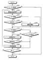
次に、運転支援装置1が実行する処理について説明する。図4は、運転支援装置1が実行する処理の概要を示すフローチャートである。[Processing of driving support device]
Next, processing executed by the driving
図4に示すように、ECU15は、乗車状況を取得する(ステップS101)。具体的には、ECU15は、通信部14を介して取得したウェアラブル装置2のGPSセンサ25からウェアラブル装置2の位置情報、IGスイッチ10からIG電源に関する状態情報、シートセンサ11の検出結果および開閉センサ12の検出結果の各々を車両100とユーザとの相対的な位置関係を示す乗車状況として取得する。 As shown in FIG. 4, the ECU 15 acquires the boarding status (step S101). Specifically, the ECU 15 acquires the position information of the
続いて、ECU15は、ユーザが車両100に乗車したか否かを判定する(ステップS102)。例えば、ECU15は、通信部14を介して取得したウェアラブル装置2のGPSセンサ25が検出した位置情報とカーナビゲーションシステム13のGPSセンサ131が検出した位置情報とに基づいて、車両100とウェアラブル装置2との距離を算出し、この算出した距離が所定値以上であるか否かを判定し、距離が所定値以上である場合、ユーザが車両100から降車したと判定する一方、距離が所定値以上でない場合、ユーザが車両100に乗車したと判定する。ECU15によってユーザが車両100に乗車したと判定された場合(ステップS102:Yes)、運転支援装置1は、後述するステップS103へ移行する。これに対して、ECU15によってユーザが車両100に乗車していないと判定された場合(ステップS102:No)、運転支援装置1は、後述するステップS106へ移行する。 Subsequently, the ECU 15 determines whether or not the user has boarded the vehicle 100 (step S102). For example, the ECU 15 detects the
ステップS103において、ECU15は、ユーザがウェアラブル装置2を装着しているか否かを判定する。具体的には、ECU15は、通信部14を介してウェアラブル装置2の装着センサ26から検出結果を示す装着信号を受信し、受信した装着信号に基づいて、ユーザがウェアラブル装置2を装着しているか否かを判定する。ECU15によってユーザがウェアラブル装置2を装着していると判定された場合(ステップS103:Yes)、運転支援装置1は、後述するステップS104へ移行する。これに対して、ECU15によってユーザがウェアラブル装置2を装着していないと判定された場合(ステップS103:No)、運転支援装置1は、後述するステップS106へ移行する。 In step S103, the ECU 15 determines whether the
ステップS104において、ECU15は、通信部14を介してウェアラブル装置2の撮像装置21が動画を録画中であるか否かを判定する。ECU15によってウェアラブル装置2の撮像装置21が動画を記録中であると判定された場合(ステップS104:Yes)、運転支援装置1は、後述するステップS106へ移行する。これに対して、ECU15によってウェアラブル装置2の撮像装置21が動画を記録中でないと判定された場合(ステップS104:No)、運転支援装置1は、後述するステップS105へ移行する。 In step S<b>104 , the ECU 15 determines whether or not the
ステップS105において、ECU15は、通信部14を介してウェアラブル装置2の撮像装置21に対して動画の録画を開始させる。具体的には、ECU15は、通信部14を介してウェアラブル装置2の撮像装置21に対して動画撮影を指示するREC信号を送信する。これにより、ユーザが車両100に乗車した際に、ウェアラブル装置2による録画が自動的に開始される。ステップS105の後、運転支援装置1は、後述するステップS106へ移行する。 In step S<b>105 , the ECU 15 causes the
続いて、ECU15は、ユーザが車両100から降車したか否かを判定する(ステップS106)。例えば、ECU15は、通信部14を介して取得したウェアラブル装置2のGPSセンサ25が検出した位置情報とカーナビゲーションシステム13のGPSセンサ131が検出した位置情報とに基づいて、車両100とウェアラブル装置2との距離を算出し、この算出した距離が所定値以上であるか否かを判定し、距離が所定値以上である場合、ユーザが車両100から降車したと判定する一方、距離が所定値以上でない場合、ユーザが車両100に乗車したと判定する。なお、ECU15は、開閉センサ12から入力される検出結果およびシートセンサ11の検出結果に基づいて、ユーザが車両100を降車したか否かを判定してもよい。ECU15によってユーザが車両100から降車したと判定された場合(ステップS106:Yes)、運転支援装置1は、後述するステップS107へ移行する。これに対して、ECU15によってユーザが車両100から降車していないと判定された場合(ステップS106:No)、運転支援装置1は、後述するステップS111へ移行する。 Subsequently, the ECU 15 determines whether or not the user has gotten off the vehicle 100 (step S106). For example, the ECU 15 detects the
ステップS107において、ECU15は、ウェアラブル装置2の撮像装置21による動画の記録を停止する。具体的には、ECU15は、通信部14を介してウェアラブル装置2の撮像装置21による動画の記録を停止させる停止信号を送信する。 In step S<b>107 , the ECU 15 stops recording the moving image by the
続いて、ECU15は、通信部14を介してウェアラブル装置2または図示しないサーバから録画指示があるか否かを判定する(ステップS108)。具体的には、ECU15は、車両100の周辺環境において緊急事態の場合、例えば車両100が交通事故、火災および天災等の発生に遭遇した場合において、通信部14を介して図示しないサーバから送信される録画を開始する開始信号が入力されたとき、サーバから録画指示があったと判定する。また、ECU15は、通信部14を介してウェアラブル装置2の9軸センサ22から所定値以上の加速度を検出した検出結果が入力された場合、この検出結果を開始信号として入力を受け付ける。ECU15によってウェアラブル装置2または図示しないサーバから録画指示があったと判定された場合(ステップS108:Yes)、運転支援装置1は、後述するステップS109へ移行する。これに対して、ECU15によってウェアラブル装置2または図示しないサーバから録画指示がなかったと判定された場合(ステップS108:No)、運転支援装置1は、後述するステップS110へ移行する。 Subsequently, the ECU 15 determines whether or not there is a recording instruction from the
ステップS109において、ECU15は、通信部14を介してウェアラブル装置2の撮像装置21にREC信号を送信することによって動画を一定時間録画させる。これにより、ウェアラブル装置2は、ECU15によって動画撮影機能に制限が掛けられて録画が禁止されている場合であっても、車両100の周辺環境において事故や事件等に遭遇したとき、録画を開始することができるので、証拠動画として用いることができたり、火事や天災等の突発的な状況を記録することができたりする。 In step S<b>109 , the ECU 15 transmits a REC signal to the
続いて、ECU15は、IGスイッチ10がオフ状態となったか否かを判定する(ステップS110)。ECU15によってIGスイッチ10がオフ状態であると判定された場合(ステップS110:Yes)、運転支援装置1は、本処理を終了する。これに対して、ECU15によってIGスイッチ10がオフ状態でないと判定された場合(ステップS110:No)、運転支援装置1は、上述したステップS101へ戻る。 Subsequently, the ECU 15 determines whether or not the
ステップS111において、ECU15は、ユーザがウェアラブル装置2を脱衣したか否かを判定する。具体的には、ECU15は、通信部14を介してウェアラブル装置2の装着センサ26から検出結果を取得し、取得した検出結果に基づいて、ユーザがウェアラブル装置2を脱衣したか否かを判定する。ECU15によってユーザがウェアラブル装置2を脱衣していると判定された場合(ステップS111:Yes)、運転支援装置1は、ステップS107へ移行する。これに対して、ECU15によってユーザがウェアラブル装置2を脱衣していないと判定された場合(ステップS111:No)、運転支援装置1は、後述するステップS110へ移行する。 In step S111, the ECU 15 determines whether or not the
以上説明した実施の形態1によれば、ECU15が車両100に対するユーザの乗車状況に基づいて、ウェアラブル装置2が有する機能であって、プライバシーに関わる情報を取得する機能を切り替える制御を行うことによって、ウェアラブル装置2によって取得可能な各種情報がユーザや他者の意図しない形で使用されることを防止することができるので、ユーザや他者へのプライバシーに対して配慮した動作を行うことができる。 According to the first embodiment described above, the ECU 15 performs control to switch the function of the
また、実施の形態1によれば、ECU15が運転支援装置1とウェアラブル装置2との距離が所定値以上であるか否かを判定し、運転支援装置1とウェアラブル装置2との距離が所定値以上であると判定した場合、ユーザが車両100から降車したと判定し、ウェアラブル装置2の撮像装置21による録画を停止する一方、運転支援装置1とウェアラブル装置2との距離が所定値以上でないと判定した場合、ユーザが車両100に乗車したと判定し、ウェアラブル装置2の撮像装置21による録画を開始するので、ユーザがウェアラブル装置2を装着したまま車両100を降車した場合であっても、ウェアラブル装置2によって取得可能な情報がユーザや他者の意図しない形で使用されることを防止することができ、かつ、ユーザが車両100に乗車した場合、ウェアラブル装置2によって取得された情報を用いた運転支援を行うことができる。 Further, according to
また、実施の形態1によれば、ECU15が車両100にユーザが乗車したと判定した場合において、ユーザがウェアラブル装置2を装着していないと判定したとき、ウェアラブル装置の撮像装置21による録画を停止して禁止する一方、車両100にユーザが乗車したと判定した場合において、ユーザがウェアラブル装置2を装着していると判定したとき、ウェアラブル装置の撮像装置21による録画を開始することによって、車両100の乗車時のみウェアラブル装置2を装着するユーザに対して、ウェアラブル装置2を装着するまで、ウェアラブル装置2による情報の取得を防止することができるので、ユーザや他者へのプライバシーに対して配慮した動作を行うことができるうえ、ウェアラブル装置2の消費電力の低減を図ることができる。 Further, according to the first embodiment, when the ECU 15 determines that the user has boarded the
また、実施の形態1によれば、ECU15がウェアラブル装置2の撮像装置21による動画撮影を停止している場合において、サーバから開始信号が入力されたとき、ウェアラブル装置2の撮像装置21による動画撮影を開始するので、ユーザが車両100から降車している場合や車両100の運転を終了している場合であっても、緊急時にウェアラブル装置2の撮像装置21によって録画を開始することができるので、証拠動画として用いることができたり、または火事や天災等の突発的な状況を記録することができたりする。 Further, according to
また、実施の形態1によれば、ECU15がウェアラブル装置2の動画撮影機能、動画データを記録する記録機能、動画データ、位置情報およびバイタル情報のいずれか一つ以上を送信する送信機能、GPSセンサ25が位置情報を取得する取得機能および投影部24が画像を投影する投影機能のいずれか一つ以上を切り替える制御を行うことによって、ウェアラブル装置2によって取得可能な各種情報がユーザや他者の意図しない形で使用されることを防止することができるので、ユーザや他者へのプライバシーに対して配慮した動作を行うことができる。 Further, according to
なお、実施の形態1では、ECU15がIGスイッチ10の状態または車両100の電源を起動する起動スイッチ(READYスイッチ)の状態に基づいて、車両100に対するユーザの乗車状況を判定してもよい。この場合において、ECU15は、IGスイッチ10の状態または起動スイッチの状態がオフ状態であるか否かを判定し、IGスイッチ10の状態または起動スイッチの状態がオフ状態であるとき、ユーザが車両100から降車したと判定し、ウェアラブル装置2の撮像装置21による動画撮影の録画を停止する一方、IGスイッチ10の状態または起動スイッチの状態がオン状態であるとき、ユーザが車両100に乗車したと判定し、ウェアラブル装置の撮像装置21による動画撮影の録画を開始する。これにより、ユーザが車両100の運転を終えてウェアラブル装置2を装着したまま車両100を降車した場合であっても、ウェアラブル装置2によって取得可能な各種情報がユーザや他者の意図しない形で使用されることを防止することができ、かつ、ユーザが車両100に乗車して車両100の運転を開始した場合、ウェアラブル装置2によって各種情報を取得することができるので、ウェアラブル装置2によって取得された情報を用いた運転支援を行うことができる。 In the first embodiment, the ECU 15 may determine the user's boarding status of the
また、実施の形態1では、ECU15がウェアラブル装置2から受信した信号の信号強度に基づいて、車両100に対するユーザの乗車状況を判定してもよい。この場合において、ECU15は、ウェアラブル装置2から受信した信号の信号強度が所定値未満であるか否かを判定し、信号強度が所定値未満であるとき、ユーザが車両100から降車したと判定し、ウェアラブル装置2の撮像装置21による録画を停止する一方、信号強度が所定値未満でないとき、ユーザが車両100に乗車すると判定し、ウェアラブル装置の撮像装置21による録画を開始する。これにより、ユーザがウェアラブル装置2を装着したまま車両100を降車した場合であっても、ウェアラブル装置2によって取得可能な各種情報がユーザや他者の意図しない形で使用されることを防止することができ、かつ、ユーザが車両100に乗車した場合、ウェアラブル装置2によって各種情報を取得することができるので、ウェアラブル装置2によって取得された情報を用いた運転支援を行うことができる。 Further, in
また、実施の形態1では、開閉センサ12から入力される検出結果およびシートセンサ11の検出結果に基づいて、ユーザが車両100に乗車したか否かを判定してもよい。この場合、ECU15は、開閉センサ12から取得した検出結果に基づいて、車両100のドアが開いたか否かを判定する。そして、ECU15は、車両100のドアが開いたと判定したとき、シートセンサ11の検出結果に基づいて、ユーザが運転席に対して着座したか否かを判定し、ユーザが運転席に対して着座していると判定したとき、ユーザが車両100に乗車したと判定し、ユーザが車両100に乗車したと判定し、ウェアラブル装置の撮像装置21による動画撮影の録画を開始する。これに対して、ECU15は、ユーザが運転席に対して着座していないと判定したとき、ユーザが車両100から降車したと判定し、ウェアラブル装置2の撮像装置21による動画撮影の録画を停止する。これにより、ユーザが車両100の運転を終えてウェアラブル装置2を装着したまま車両100を降車した場合であっても、ウェアラブル装置2によって取得可能な各種情報がユーザや他者の意図しない形で使用されることを防止することができ、かつ、ユーザが車両100に乗車して車両100の運転を開始した場合、ウェアラブル装置2によって取得された情報を用いた運転支援を行うことができる。 Further, in
また、実施の形態1では、ECU15がウェアラブル装置2の撮像装置21によって撮像された画像データに基づいて、車両100に対するユーザの乗車状況を判定してもよい。この場合において、ECU15は、ウェアラブル装置2の撮像装置21によって撮像された画像データに基づいて、ユーザが車両100から降車したと判定した場合、ウェアラブル装置による動画データの記録機能、ウェアラブル装置2の送信機能、投影部24が画像を投影する投影機能のいずれかを一つ以上を停止する一方、ユーザが車両100に乗車したと判定した場合、ウェアラブル装置2の送信機能、記録機能、投影部24が画像を投影する投影機能のいずれかを一つ以上を開始する。これにより、ユーザがウェアラブル装置を装着したまま車両を降車した場合であっても、ウェアラブル装置によって取得可能な各種情報がユーザや他者の意図しない形で使用されることを防止することができ、かつ、ユーザが車両に乗車した場合、ウェアラブル装置によって各種情報を取得することができるので、ウェアラブル装置2によって取得された情報を用いた運転支援を行うことができる。 Further, in
また、実施の形態1では、ECU15がユーザの乗車状況に基づいて、ウェアラブル装置の投影部24が投影する画像の表示内容を切り替えてもよい。具体的には、ECU15は、運転支援装置1とウェアラブル装置2との距離が所定値以上であるか否かを判定し、運転支援装置1とウェアラブル装置2との距離が所定値以上であると判定した場合、ユーザが車両100から降車した状態であると判定し、投影部24が投影する画像をユーザが歩行に適した表示内容に切り替える。ここで、ユーザが歩行に適した表示内容とは、GPSセンサ25に基づく周辺情報、例えばグルメ情報、イベント情報および観光地情報等である。これに対して、ECU15は、運転支援装置1とウェアラブル装置2との距離が所定値以上でないと判定した場合、ユーザが車両100に乗車した状態であると判定し、投影部24が投影する画像をユーザの運転を支援する表示内容に切り替える。ここで、運転を支援する表示内容とは、車両100の速度情報、運転支援装置1のカーナビゲーションシステム13から送信された地図情報および道路情報等である。これにより、ユーザの乗車状況に応じて、ウェアラブル装置2が投影する画像の表示内容を切り替えるので、ユーザの乗車状況に応じた表示を行うことができる。 In
また、実施の形態1では、ECU15が通信部14を介してウェアラブル装置2のGPSセンサ25が検出した位置情報とカーナビゲーションシステム13のGPSセンサ131が検出した位置情報とに基づいて、車両100とウェアラブル装置2との距離を算出していたが、例えば通信部14を介して他車と車車間通信や路車間通信を行うことによって取得した画像データに基づいて、車両100とウェアラブル装置2と距離を算出してもよい。 Further, in the first embodiment, the ECU 15 communicates with the
また、実施の形態1では、ECU15が通信部14およびネットワークを介して、ウェアラブル装置2が図示しないサーバ上にアップロードしたウェアラブル装置2の位置情報をサーバから取得し、取得したウェアラブル装置の位置情報とカーナビゲーションシステム13のGPSセンサ131が検出した位置情報とに基づいて、車両100とウェアラブル装置2と距離を算出してもよい。もちろん、ECU15は、通信部14およびネットワークを介して、ウェアラブル装置2の位置情報以外に、ウェアラブル装置2の撮像装置21によって撮像された画像データをサーバから取得することによって、車両100とユーザとの相対的な位置関係を示す乗車状況を判定してもよい。 Further, in the first embodiment, the ECU 15 acquires from the server, via the communication unit 14 and the network, the position information of the
(実施の形態2)
次に、実施の形態2について説明する。実施の形態2に係る運転システムは、上述した実施の形態1に係る運転支援システム1000と同一の構成を有し、ウェアラブル装置が実行する処理が異なる。具体的には、上述した実施の形態1では、車両100に設けられた運転支援装置1がウェアラブル装置2の録画機能をユーザの乗車状況に基づいて、切り替える制御を行っていたが、実施の形態2では、ウェアラブル装置がユーザの乗車状況に基づいて、録画機能を切り替える制御を行う。以下においては、実施の形態2に係るウェアラブル装置が実行する処理について説明する。なお、上述した実施の形態1に係る運転支援システム1000と同一の構成には同一の符号を付して詳細な説明は省略する。(Embodiment 2)
Next,
〔ウェアラブル装置の処理〕
実施の形態2に係るウェアラブル装置2が実行する処理について説明する。図5は、ウェアラブル装置2が実行する処理の概要を示すフローチャートである。[Processing of wearable device]
Processing executed by the
図5に示すように、まず、制御部27は、装着センサ26から入力された検出結果を示す装着信号に基づいて、ユーザがウェアラブル装置2を装着しているか否かを判定する(ステップS201)。制御部27によってユーザがウェアラブル装置2を装着していると判定された場合(ステップS201:Yes)、ウェアラブル装置2は、後述するステップS202へ移行する。これに対して、制御部27によってユーザがウェアラブル装置2を装着していないと判定された場合(ステップS201:No)、ウェアラブル装置2は、本処理を終了する。 As shown in FIG. 5, first, the control unit 27 determines whether or not the
続いて、制御部27は、通信部20を介して運転支援装置1から車両100とユーザとの相対的な位置関係を示す乗車状況を取得し(ステップS202)、ユーザが車両100に乗車したか否かを判定する(ステップS203)。具体的には、制御部27は、通信部20を介して運転支援装置1のGPSセンサ131から車両100の位置情報およびGPSセンサ25が算出した位置情報に基づいて、車両100とウェアラブル装置2との距離を算出し、この距離が所定値以上であるか判定し、距離が所定値以上であると判定した場合、ユーザが車両100から降車した状態であると判定し、距離が所定値以上であると判定した場合、ユーザが車両100から降車した状態であると判定し、距離が所定値以上でないと判定した場合、ユーザが車両100に乗車した状態であると判定する。制御部27によってユーザが車両100に乗車したと判定された場合(ステップS203:Yes)、ウェアラブル装置2は、後述するステップS204へ移行する。これに対して、制御部27によってユーザが車両100に乗車していないと判定された場合(ステップS203:No)、ウェアラブル装置2は、後述するステップS206へ移行する。 Subsequently, the control unit 27 acquires the riding situation indicating the relative positional relationship between the
ステップS204~ステップS211は、上述した図3のステップS104~ステップS111それぞれに対応する。 Steps S204 to S211 correspond to steps S104 to S111 in FIG. 3 described above, respectively.
以上説明した実施の形態2によれば、制御部27が車両100に対するユーザの乗車状況に基づいて、ウェアラブル装置2が有するプライバシーに関わる情報を取得可能な所定の機能を切り替える制御を行うことによって、ウェアラブル装置2によって取得可能な各種情報がユーザや他者の意図しない形で使用されることを防止することができるので、ウェアラブル装置2によって取得された情報を用いた運転支援を行うことができる。 According to the second embodiment described above, the control unit 27 performs control to switch a predetermined function capable of acquiring privacy-related information possessed by the
なお、実施の形態2では、制御部27が運転支援装置1とウェアラブル装置2との距離に基づいて、車両100とユーザとの相対的な位置関係を示す乗車状況を判定していたが、上述した実施の形態1と同様に、距離以外に、IGスイッチ10の状態または車両100の電源を起動する起動スイッチ(READYスイッチ)の状態、シートセンサ11または開閉センサ12の検出結果、ウェアラブル装置2から受信する信号の信号強度およびウェアラブル装置2の撮像装置21によって撮像された画像データのいずれか1つ以上に基づいて、車両100とユーザとの相対的な位置関係を示す乗車状況を判定してもよい。 In the second embodiment, the control unit 27 determines the riding situation indicating the relative positional relationship between the
また、実施の形態2では、制御部27が運転支援装置1から乗車状況を取得していたが、例えば通信部20を介して他車と車車間通信や路車間通信を行い、他車が車両100とウェアラブル装置2を装着したユーザとを撮像した画像データを取得することによって、車両100に対するユーザの乗車状況を判定し、この判定結果に基づいて、ウェアラブル装置2が有するプライバシーに関わる情報を取得可能な所定の機能を切り替える制御を行ってもよい。 In addition, in the second embodiment, the control unit 27 acquires the boarding status from the driving
また、実施の形態2では、制御部27が通信部20およびネットワークを介して、運転支援装置1が図示しないサーバ上にアップロードした車両100とユーザとの相対的な位置関係を示す乗車状況をサーバから取得し、この取得した乗車状況に基づいて、ウェアラブル装置2が有するプライバシーに関わる情報を取得可能な所定の機能を切り替える制御を行ってもよい。 Further, in the second embodiment, the control unit 27 receives the riding situation showing the relative positional relationship between the
(実施の形態3)
次に、実施の形態3について説明する。上述した実施の形態1では、運転支援装置1のECU15がユーザの乗車状況に基づいて、ウェアラブル装置2の録画記録を切り替えていたが、実施の形態3では、サーバが運転支援装置およびウェアラブル装置の各々から乗車状況を取得することによってウェアラブル装置の録画機能を切り替える制御を行う。なお、上述した実施の形態1に係る運転支援システム1000と同一の構成には同一の符号を付して詳細な説明は省略する。(Embodiment 3)
Next, Embodiment 3 will be described. In the first embodiment described above, the ECU 15 of the driving
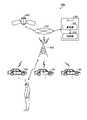
図6は、実施の形態3に係る運転支援システムの概略構成を示す模式図である。図6に示す運転支援システム1001は、複数の車両100の各々に搭載された運転支援装置1と、ユーザU1が装着したウェアラブル装置2と、サーバ300と、を備える。複数の運転支援装置1、ウェアラブル装置2およびサーバ300は、基地局400およびネットワーク500を介して相互に情報通信可能に構成されている。また、サーバ300は、基地局400およびネットワーク500を介してGPS衛星600から車両100の上空を撮像もしくは、車車間通信によって取得した他車画像から作像して画像データを取得する。 FIG. 6 is a schematic diagram showing a schematic configuration of a driving support system according to Embodiment 3. As shown in FIG. A driving
〔サーバの構成〕
次に、サーバ300の構成について説明する。サーバ300は、通信部301と、制御部302と、を備える。[Server configuration]
Next, the configuration of
通信部301は、制御部302の制御のもと、ネットワーク500および基地局400を介して所定の通信規格に従って各種情報を送信するとともに、各種情報を受信する。また、通信部301は、制御部302の制御のもと、各車両100の運転支援装置1およびウェアラブル装置2に対して所定の通信規格に従って各種情報を送信するとともに、GPS衛星600、各車両100の運転支援装置1およびウェアラブル装置2から各種情報を受信する。通信部301は、無線通信可能な通信モジュールを用いて構成される。なお、実施の形態3では、運転支援装置1の機能をウェアラブル装置2に内蔵させてもよい。 Under the control of the
制御部302は、メモリと、CPUまたは複数のニューラルネットワークで構成されたディープラーニング等の機械学習で用いられるAIチィップ等のハードウェアを有するプロセッサを用いて構成される。制御部302は、通信部301を介して、運転支援装置1が搭載された車両100の位置情報とウェアラブル装置2の位置情報とに基づいて、ユーザU1が車両100に乗車したか否かを判定し、車両100に乗車している場合、ウェアラブル装置2による動画の録画を開始させるREC信号をウェアラブル装置2へ送信する一方、ユーザU1が車両100から降車した場合、ウェアラブル装置2による動画の録画を停止させる停止信号をウェアラブル装置2へ送信する。なお、制御部302は、GPS衛星600から画像データを取得し、取得した画像データに対応する画像から車両100とウェアラブル装置2との距離を算出し、この距離が所定未満である場合、ユーザU1が車両100に搭乗していると判定し、ウェアラブル装置2にREC信号を送信するようにしてもよい。 The
以上説明した実施の形態3によれば、制御部302が通信部301を介して運転支援装置1が搭載された車両100の位置情報とウェアラブル装置2の位置情報とに基づいて、ユーザU1が車両100に乗車したか否かを判定し、車両100に乗車している場合、ウェアラブル装置2による動画の録画を開始させるREC信号をウェアラブル装置2へ送信する一方、ユーザU1が車両100から降車した場合、ウェアラブル装置2による動画の録画を停止させる停止信号をウェアラブル装置2へ送信するので、ユーザがウェアラブル装置2を装着したまま車両100を降車した場合であっても、ウェアラブル装置2によって取得可能な各種情報がユーザや他者の意図しない形で使用されることを防止することができ、かつ、ユーザが車両100に乗車した場合、ウェアラブル装置2によって各種情報を取得することができるので、ウェアラブル装置2によって取得された情報を用いた運転支援を行うことができる。 According to the third embodiment described above, based on the position information of the
なお、実施の形態3では、制御部302が運転支援装置1とウェアラブル装置2との距離に基づいて、車両100とユーザとの相対的な位置関係を示す乗車状況を判定していたが、上述した実施の形態1と同様に、距離以外に、IGスイッチ10の状態または車両100の電源を起動する起動スイッチ(READYスイッチ)の状態、シートセンサ11または開閉センサ12の検出結果、ウェアラブル装置2から受信する信号の信号強度およびウェアラブル装置2の撮像装置21によって撮像された画像データのいずれか1つ以上に基づいて、車両100とユーザとの相対的な位置関係を示す乗車状況を判定してもよい。 In the third embodiment, the
また、実施の形態3では、制御部302が運転支援装置1とウェアラブル装置2との距離に基づいて、車両100とユーザとの相対的な位置関係を示す乗車状況を判定していたが、例えば他の車両100が撮像した画像データ、車車間通信や路車間通信等で取得された情報に基づいて、車両100とユーザとの相対的な位置関係を示す乗車状況を判定してもよい。 Further, in Embodiment 3, the
(実施の形態1~3に係る変形例)
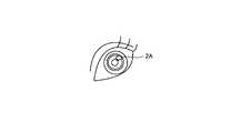
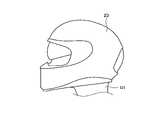
なお、実施の形態1~3では、運転者が装着可能な眼鏡型のウェアラブル装置2を用いた例を説明していたが、これに限定されることなく、種々のウェアラブル装置に適用することができる。例えば図7に示すように撮像機能を有するコンタクトレンズ型のウェアラブル装置2Aであっても適用することができる。さらに、図8のウェアラブル装置2Bまたは図9の脳内チップ型のウェアラブル装置2CのようにユーザU1の脳へ直接的に伝達する装置であっても適用することができる。さらにまた、図10のウェアラブル装置2Dのようにバイザーを備えたヘルメット形状に構成されてもよい。この場合は、ウェアラブル装置2Dは、バイザーに画像を投影して表示するものであってもよい。(Modifications according to
In
また、実施の形態1~3では、ウェアラブル装置2が運転者の網膜に投影することによって画像を視認させていたが、例えば眼鏡等のレンズに画像を投影して表示するものであってもよい。 Further, in
また、実施の形態2では、ウェアラブル装置2が運転者の網膜に投影することによって画像を視認させていたが、例えば眼鏡等のレンズに画像を投影して表示するものであってもよい。 Further, in
(その他の実施の形態)
また、実施の形態1~3では、上述してきた「部」を、「回路」などに読み替えることができる。例えば、制御部は、制御回路に読み替えることができる。(Other embodiments)
Further, in
また、実施の形態1~3に係る運転支援装置では、ECUまたは制御部がウェアラブル装置の機能であって、プライバシーに関わる情報を取得する機能の動作を切り替える制御を行っていたが、これに限定されることなく、ECUやGPU(Graphics Processing Unit)に代えて、ECUやGPUより適したデバイス、例えばFPGA(Field Programmable Gate Array)、DSP(Digital Signal Processing)およびメモリ等で構成されるデバイスやニューラルネットワークを用いた機械学習等のデータ処理および画像処理に用いられるAIチップが行ってもよい。 Further, in the driving support devices according to the first to third embodiments, the ECU or the control unit is a function of the wearable device, and performs control to switch the operation of the function of acquiring information related to privacy, but is limited to this. Instead of ECUs and GPUs (Graphics Processing Units), devices that are more suitable than ECUs and GPUs, such as FPGAs (Field Programmable Gate Arrays), DSPs (Digital Signal Processing), memory devices, and neural devices An AI chip used for data processing such as machine learning using a network and image processing may perform.
また、実施の形態1~3に係る運転支援装置およびウェアラブル装置に実行させるプログラムは、インストール可能な形式または実行可能な形式のファイルデータでCD-ROM、フレキシブルディスク(FD)、CD-R、DVD(Digital Versatile Disk)、USB媒体、フラッシュメモリ等のコンピュータで読み取り可能な記録媒体に記録されて提供される。 Further, the program to be executed by the driving support device and the wearable device according to
また、実施の形態1~3に係る運転支援装置およびウェアラブル装置に実行させるプログラムは、インターネット等のネットワークに接続されたコンピュータ上に格納し、ネットワーク経由でダウンロードさせることにより提供するように構成してもよい。 Further, the programs to be executed by the driving support device and the wearable device according to
なお、本明細書におけるフローチャートの説明では、「まず」、「その後」、「続いて」等の表現を用いてステップ間の処理の前後関係を明示していたが、本実施の形態を実施するために必要な処理の順序は、それらの表現によって一意的に定められるわけではない。即ち、本明細書で記載したフローチャートにおける処理の順序は、矛盾のない範囲で変更することができる。 In addition, in the description of the flowcharts in this specification, expressions such as "first", "after", and "following" are used to clearly indicate the anteroposterior relationship of the processing between steps. The order of processing required to do so is not uniquely determined by those representations. That is, the order of processing in the flow charts described herein may be changed within a consistent range.
さらなる効果や変形例は、当業者によって容易に導き出すことができる。本発明のより広範な態様は、以上のように表しかつ記述した特定の詳細および代表的な実施の形態に限定されるものではない。従って、添付のクレームおよびその均等物によって定義される総括的な発明の概念の精神または範囲から逸脱することなく、様々な変更が可能である。 Further effects and modifications can be easily derived by those skilled in the art. The broader aspects of the invention are not limited to the specific details and representative embodiments shown and described above. Accordingly, various changes may be made without departing from the spirit or scope of the general inventive concept defined by the appended claims and equivalents thereof.
1 運転支援装置
2,2A,2B,2C ウェアラブル装置
10 IGスイッチ
11 シートセンサ
12 開閉センサ
13 カーナビゲーションシステム
14,20,301 通信部
15 ECU
21 撮像装置
22 9軸センサ
23 視線センサ
24 投影部
25,131 GPSセンサ
26 装着センサ
27,302 制御部
100 車両
300 サーバ
1000,1001 運転支援システム1 driving
21 imaging device 22 9-axis sensor 23 line-of-sight sensor 24
Claims (16)
Translated fromJapaneseハードウェアを有するプロセッサと、
を備え、
前記プロセッサは、
車両とユーザとの相対的な位置関係を示す乗車状況に基づいて、ユーザが装着するウェアラブル装置が有する撮像装置による録画機能の動作を切り替える制御を行う、
運転支援装置。memory;
a processor having hardware;
with
The processor
Based on the riding situation indicating the relative positional relationship between the vehicle and the user, control is performed to switch the operation of therecording function by the imaging device of the wearable device worn by the user.
Driving assistance device.
前記プロセッサは、
当該運転支援装置と前記ウェアラブル装置との距離が所定値以上であるか否かを判定し、
前記距離が前記所定値以上であると判定した場合、前記ユーザが前記車両から降車した状態であると判定し、前記録画機能を停止する一方、
前記距離が前記所定値以上でないと判定した場合、前記ユーザが前記車両に乗車した状態であると判定し、前記録画機能を開始する、
運転支援装置。The driving support device according to claim 1,
The processor
determining whether the distance between the driving support device and the wearable device is equal to or greater than a predetermined value;
If it is determined that the distance is equal to or greater than the predetermined value, it is determined that the user has exited the vehicle, and therecording function is stopped;
If it is determined that the distance is not equal to or greater than the predetermined value, it is determined that the user is in the vehicle, and therecording function is started.
Driving assistance device.
前記プロセッサは、
前記車両のエンジンを始動するイグニッションスイッチがオフ状態または前記車両の電源を起動する起動スイッチがオフ状態であるか否かを判定し、
前記イグニッションスイッチがオフ状態または前記起動スイッチがオフ状態である場合、前記ユーザが前記車両から降車した状態であると判定し、前記録画機能を停止する一方、
前記イグニッションスイッチがオン状態または前記起動スイッチがオン状態である場合、前記ユーザが前記車両に乗車した状態であると判定し、前記録画機能を開始する、
運転支援装置。The driving support device according to claim 1,
The processor
determining whether an ignition switch for starting an engine of the vehicle is in an OFF state or a start switch for starting a power source of the vehicle is in an OFF state;
When the ignition switch is in the OFF state or the start switch is in the OFF state, it is determined that the user has exited the vehicle, and therecording function is stopped;
If the ignition switch is onor the activation switch is on, it is determined that the user is in the vehicle, and therecording function is started.
Driving assistance device.
前記プロセッサは、
前記ウェアラブル装置から受信する信号の信号強度が所定値未満であるか否かを判定し、
前記信号強度が前記所定値未満である場合、前記ユーザが前記車両から降車した状態であると判定し、前記録画機能を停止する一方、
前記信号強度が前記所定値未満でない場合、前記ユーザが前記車両に乗車した状態であると判定し、前記録画機能を開始する、
運転支援装置。The driving support device according to claim 1,
The processor
determining whether the signal strength of the signal received from the wearable device is less than a predetermined value;
If the signal strength is less than the predetermined value, it is determined that the user has exited the vehicle, and therecording function is stopped;
If the signal strength is not less than the predetermined value, determine that the user is in the vehicle and start therecording function;
Driving assistance device.
前記車両のドアの開閉状態を検出する開閉スイッチと、
前記車両の運転席に対する着座の状態を検出するシートセンサと、
をさらに備え、
前記プロセッサは、
前記開閉スイッチが検出した検出結果および前記シートセンサの検出結果に基づいて、前記乗車状況を判定し、
前記ユーザが前記車両から降車した状態であると判定した場合、前記録画機能を停止する一方、
前記ユーザが前記車両に乗車した状態であると判定した場合、前記録画機能を開始する、
運転支援装置。The driving support device according to claim 1,
an open/close switch for detecting an open/closed state of a door of the vehicle;
a seat sensor that detects a seating state with respect to the driver's seat of the vehicle;
further comprising
The processor
determining the riding situation based on the detection result detected by the open/close switch and the detection result of the seat sensor;
When it is determined that the user has gotten off the vehicle, while stopping therecording function,
When it is determined that the user is in the vehicle, starting therecording function;
Driving assistance device.
前記プロセッサは、
他の車両または前記ウェアラブル装置が撮像した画像データに基づいて、前記乗車状況を判定し、
前記ユーザが前記車両から降車した状態であると判定した場合、前記録画機能を停止する一方、
前記ユーザが前記車両に乗車した状態であると判定した場合、前記録画機能を開始する、
運転支援装置。The driving support device according to claim 1,
The processor
determining the boarding situation based on image data captured byanother vehicle or the wearable device ;
When it is determined that the user has gotten off the vehicle, while stopping therecording function,
When it is determined that the user is in the vehicle, starting therecording function;
Driving assistance device.
前記プロセッサは、
前記ウェアラブル装置から送信された画像データに基づいて、前記乗車状況を判定し、
前記ユーザが前記車両から降車した状態であると判定した場合、前記録画機能を停止する一方、
前記ユーザが前記車両に乗車した状態であると判定した場合、前記録画機能を開始する、
運転支援装置。The driving support device according to claim 1,
The processor
Based on the image data transmitted from the wearable device, determine the riding situation,
When it is determined that the user has gotten off the vehicle, while stopping therecording function,
When it is determined that the user is in the vehicle, starting therecording function;
Driving assistance device.
前記ウェアラブル装置から送信された装着信号であって、前記ユーザが前記ウェアラブル装置の装着状態を示す装着信号に基づいて、前記ユーザが前記ウェアラブル装置を装着しているか否かを判定し、
前記ユーザが前記車両に乗車した状態であると判定された場合において、前記ユーザが前記ウェアラブル装置を装着していない状態であると判定したとき、前記録画機能を停止する一方、
前記ユーザが前記車両に乗車した状態であると判定した場合、前記録画機能を開始する、
運転支援装置。The driving support device according to any one of claims 1 to 7,
Determining whether the user is wearing the wearable device based on the wearing signal transmitted from the wearable device and indicating the wearing state of the wearable device by the user;
When it is determined that the user is not wearing the wearable device when it is determined that the user is in the vehicle, therecording function is stopped;
When it is determined that the user is in the vehicle, starting therecording function;
Driving assistance device.
前記プロセッサは、
前記録画機能が停止されている場合において、前記録画機能の動作を開始する開始信号が入力されたとき、前記録画機能を開始する、
運転支援装置。The driving support device according to any one of claims 1 to 8,
The processor
When therecording function is stopped and a start signal for starting the operation of therecording function is input, therecording function is started;
Driving assistance device.
前記ウェアラブル装置は、
動画撮影可能な撮像部と、
位置情報を取得するGPSセンサと、
前記ユーザのバイタル情報を取得するバイタルセンサと、
所定の位置に画像を投影する投影部と、
を備える、
運転支援装置。The driving support device according to any one of claims 1 to 9,
The wearable device
an imaging unit capable of shooting moving images;
a GPS sensor that acquires position information;
a vital sensor for acquiring vital information of the user;
a projection unit that projects an image at a predetermined position;
comprising
Driving assistance device.
前記ウェアラブル装置は、
所定の位置に画像を投影する投影部を備え、
前記プロセッサは、
前記乗車状況を判定し、
前記ユーザが前記車両から降車した状態であると判定した場合、前記投影部が投影する前記画像を前記ユーザが歩行に適した表示内容に切り替える一方、
前記ユーザが前記車両に乗車した状態であると判定した場合、前記投影部が投影する前記画像を、前記ユーザの運転を支援する表示内容に切り替える、
運転支援装置。The driving support device according to claim 1,
The wearable device
Equipped with a projection unit that projects an image at a predetermined position,
The processor
determining the boarding situation;
When it is determined that the user has exited the vehicle, the image projected by the projection unit is switched to display content suitable for walking by the user,
When it is determined that the user is in the vehicle, the image projected by the projection unit is switched to display content for assisting the user in driving;
Driving assistance device.
前記車両と前記ユーザとの相対的な位置関係を示す乗車状況を受信する通信部と、
ハードウェアを有するプロセッサと、
を備え、
前記プロセッサは、
前記乗車状況に基づいて、当該ウェアラブル装置が有する撮像装置による録画機能の動作を切り替える制御を行う、
ウェアラブル装置。A wearable device that can communicate bidirectionally with a vehicle and is worn by a user,
a communication unit that receives a boarding situation indicating a relative positional relationship between the vehicle and the user;
a processor having hardware;
with
The processor
Based on the riding situation, control is performed to switch the operation of therecording function by the imaging device of the wearable device.
wearable device.
前記車両と前記ユーザとの相対的な位置関係を示す乗車状況を取得し、
メモリから読み出した前記乗車状況に基づいて、前記ユーザが装着するウェアラブル装置が有する撮像装置による録画機能の動作を切り替える制御を行う、
運転支援方法。A driving assistance method executed by a driving assistance device for assisting driving by a user of a vehicle,
Acquiring a riding situation indicating a relative positional relationship between the vehicle and the user;
Based on the riding situation read from the memory, perform control to switch the operation of therecording function by the imaging device of the wearable device worn by the user;
Driving assistance method.
前記車両と前記ユーザとの相対的な位置関係を示す乗車状況を受信し、
メモリから読み出した前記乗車状況に基づいて、当該ウェアラブル装置が有する撮像装置による録画機能の動作を切り替える制御を行う、
運転支援方法。A driving support method that is bidirectionally communicable with a vehicle and executed by a wearable device worn by a user,
receiving a boarding situation indicating a relative positional relationship between the vehicle and the user;
Based on the riding situation read from the memory, control to switch the operation of therecording function by the imaging device of the wearable device;
Driving assistance method.
前記車両と前記ユーザとの相対的な位置関係を示す乗車状況を取得し、
メモリから読み出した前記乗車状況に基づいて、前記ユーザが装着するウェアラブル装置が有する撮像装置による録画機能の動作を切り替える制御を行う、
プログラム。A program to be executed by a driving support device that supports driving by a user of a vehicle,
Acquiring a riding situation indicating a relative positional relationship between the vehicle and the user;
Based on the riding situation read from the memory, perform control to switch the operation of therecording function by the imaging device of the wearable device worn by the user;
program.
前記車両と前記ユーザとの相対的な位置関係を示す乗車状況を受信し、
メモリから読み出した前記乗車状況に基づいて、当該ウェアラブル装置が有する撮像装置による録画機能の動作を切り替える制御を行う、
プログラム。A program that is bidirectionally communicable with a vehicle and executed by a wearable device worn by a user,
receiving a boarding situation indicating a relative positional relationship between the vehicle and the user;
Based on the riding situation read from the memory, control to switch the operation of therecording function by the imaging device of the wearable device;
program.
Priority Applications (3)
| Application Number | Priority Date | Filing Date | Title |
|---|---|---|---|
| JP2018217670AJP7143736B2 (en) | 2018-11-20 | 2018-11-20 | Driving support device, wearable device, driving support method and program |
| US16/672,570US11418909B2 (en) | 2018-11-20 | 2019-11-04 | Driver-assistance device, wearable device, driver-assistance method, and computer-readable recording medium |
| CN201911119023.3ACN111196230B (en) | 2018-11-20 | 2019-11-15 | Driving support device, wearable device, driving support method, and program |
Applications Claiming Priority (1)
| Application Number | Priority Date | Filing Date | Title |
|---|---|---|---|
| JP2018217670AJP7143736B2 (en) | 2018-11-20 | 2018-11-20 | Driving support device, wearable device, driving support method and program |
Publications (2)
| Publication Number | Publication Date |
|---|---|
| JP2020086726A JP2020086726A (en) | 2020-06-04 |
| JP7143736B2true JP7143736B2 (en) | 2022-09-29 |
Family
ID=70726670
Family Applications (1)
| Application Number | Title | Priority Date | Filing Date |
|---|---|---|---|
| JP2018217670AActiveJP7143736B2 (en) | 2018-11-20 | 2018-11-20 | Driving support device, wearable device, driving support method and program |
Country Status (3)
| Country | Link |
|---|---|
| US (1) | US11418909B2 (en) |
| JP (1) | JP7143736B2 (en) |
| CN (1) | CN111196230B (en) |
Families Citing this family (6)
| Publication number | Priority date | Publication date | Assignee | Title |
|---|---|---|---|---|
| US11200656B2 (en)* | 2019-01-11 | 2021-12-14 | Universal City Studios Llc | Drop detection systems and methods |
| JP2021192202A (en)* | 2020-06-05 | 2021-12-16 | トヨタ自動車株式会社 | Experience system, experience providing method and program |
| JP7537269B2 (en)* | 2020-12-21 | 2024-08-21 | トヨタ自動車株式会社 | Charging Sheet and Program |
| CN117348242A (en)* | 2022-06-28 | 2024-01-05 | 深圳市中兴微电子技术有限公司 | An information projection method, device and vehicle control system |
| CN115214535A (en)* | 2022-07-13 | 2022-10-21 | 浙江极氪智能科技有限公司 | Vehicle control method, device, system and medium |
| CN115793540A (en)* | 2022-12-01 | 2023-03-14 | 蔚来软件科技(上海)有限公司 | Clothing, driving system, and clothing-based driving equipment control method |
Citations (6)
| Publication number | Priority date | Publication date | Assignee | Title |
|---|---|---|---|---|
| JP2005034520A (en) | 2003-07-18 | 2005-02-10 | Tokai Rika Co Ltd | Physical condition monitoring system |
| JP2009214591A (en) | 2008-03-07 | 2009-09-24 | Denso Corp | Physical condition interlocking control system |
| JP2015089808A (en) | 2013-11-06 | 2015-05-11 | ハーマン インターナショナル インダストリーズ インコーポレイテッド | Adaptation of vehicle systems based on wearable devices |
| US20160039424A1 (en) | 2014-08-11 | 2016-02-11 | Lg Electronics Inc. | Wearable device and method of operating the same |
| JP2018513804A (en) | 2015-04-10 | 2018-05-31 | ローベルト ボツシユ ゲゼルシヤフト ミツト ベシユレンクテル ハフツングRobert Bosch Gmbh | Privacy-protected remote view system |
| JP2018092415A (en) | 2016-12-05 | 2018-06-14 | 株式会社デンソーテン | Wearable terminal and method to estimate status of wearer thereof |
Family Cites Families (21)
| Publication number | Priority date | Publication date | Assignee | Title |
|---|---|---|---|---|
| JP2003179917A (en) | 2001-12-08 | 2003-06-27 | Shigeaki Kawai | Service-recording system in automobile operation |
| JP2010062778A (en) | 2008-09-03 | 2010-03-18 | Nec Saitama Ltd | Image shooting device and method of controlling image shooting |
| JP5316995B2 (en) | 2009-10-26 | 2013-10-16 | 株式会社ユピテル | Vehicle recording device |
| US11203355B2 (en)* | 2011-04-22 | 2021-12-21 | Emerging Automotive, Llc | Vehicle mode for restricted operation and cloud data monitoring |
| US8885877B2 (en) | 2011-05-20 | 2014-11-11 | Eyefluence, Inc. | Systems and methods for identifying gaze tracking scene reference locations |
| WO2013074899A1 (en)* | 2011-11-16 | 2013-05-23 | Flextronics Ap, Llc | Configurable dash display |
| US9883340B2 (en)* | 2012-08-10 | 2018-01-30 | Here Global B.V. | Method and apparatus for providing group route recommendations |
| CN104102007A (en)* | 2013-04-12 | 2014-10-15 | 聚晶半导体股份有限公司 | Head-mounted display and control method thereof |
| KR20150026336A (en)* | 2013-09-02 | 2015-03-11 | 엘지전자 주식회사 | Wearable display device and method of outputting content thereof |
| US9098956B2 (en)* | 2013-09-26 | 2015-08-04 | Lytx, Inc. | Dynamic uploading protocol |
| US9619718B2 (en)* | 2013-12-18 | 2017-04-11 | Johnson Controls Technology Company | In-vehicle camera and alert systems |
| EP2891589B1 (en)* | 2014-01-06 | 2024-09-25 | Harman International Industries, Incorporated | Automatic driver identification |
| KR101942793B1 (en)* | 2015-07-03 | 2019-01-28 | 엘지전자 주식회사 | Driver Assistance Apparatus and Vehicle Having The Same |
| KR101730321B1 (en)* | 2015-08-03 | 2017-04-27 | 엘지전자 주식회사 | Driver assistance apparatus and control method for the same |
| JP2017068595A (en) | 2015-09-30 | 2017-04-06 | ソニー株式会社 | Information processing device, information processing method, and program |
| US9900315B2 (en)* | 2015-10-30 | 2018-02-20 | GM Global Technology Operations LLC | Enabling and inhibiting synchronization of privacy settings |
| IL243772B (en)* | 2016-01-25 | 2018-03-29 | Everysight Ltd | Line-of-sight-based content-sharing dynamic ad-hoc networks |
| JP6593803B2 (en)* | 2017-03-10 | 2019-10-23 | 株式会社Subaru | Image display device |
| US11270595B2 (en)* | 2018-10-03 | 2022-03-08 | T-Mobile Usa, Inc. | Mobile aerial drone early warning privacy breach detect, intercept, and defend systems and methods |
| US10820141B2 (en)* | 2018-11-16 | 2020-10-27 | Here Global B.V. | Method and apparatus for presenting privacy-respectful and personalized location-based comments based on passenger context and vehicle proximity to the location |
| US20200177841A1 (en)* | 2018-11-29 | 2020-06-04 | International Business Machines Corporation | Obtaining video from vehicles |
- 2018
- 2018-11-20JPJP2018217670Apatent/JP7143736B2/enactiveActive
- 2019
- 2019-11-04USUS16/672,570patent/US11418909B2/enactiveActive
- 2019-11-15CNCN201911119023.3Apatent/CN111196230B/enactiveActive
Patent Citations (6)
| Publication number | Priority date | Publication date | Assignee | Title |
|---|---|---|---|---|
| JP2005034520A (en) | 2003-07-18 | 2005-02-10 | Tokai Rika Co Ltd | Physical condition monitoring system |
| JP2009214591A (en) | 2008-03-07 | 2009-09-24 | Denso Corp | Physical condition interlocking control system |
| JP2015089808A (en) | 2013-11-06 | 2015-05-11 | ハーマン インターナショナル インダストリーズ インコーポレイテッド | Adaptation of vehicle systems based on wearable devices |
| US20160039424A1 (en) | 2014-08-11 | 2016-02-11 | Lg Electronics Inc. | Wearable device and method of operating the same |
| JP2018513804A (en) | 2015-04-10 | 2018-05-31 | ローベルト ボツシユ ゲゼルシヤフト ミツト ベシユレンクテル ハフツングRobert Bosch Gmbh | Privacy-protected remote view system |
| JP2018092415A (en) | 2016-12-05 | 2018-06-14 | 株式会社デンソーテン | Wearable terminal and method to estimate status of wearer thereof |
Also Published As
| Publication number | Publication date |
|---|---|
| JP2020086726A (en) | 2020-06-04 |
| US20200162844A1 (en) | 2020-05-21 |
| CN111196230A (en) | 2020-05-26 |
| US11418909B2 (en) | 2022-08-16 |
| CN111196230B (en) | 2023-06-23 |
Similar Documents
| Publication | Publication Date | Title |
|---|---|---|
| JP7143736B2 (en) | Driving support device, wearable device, driving support method and program | |
| KR102667182B1 (en) | Vehicle control device and vehicle control method | |
| KR102552285B1 (en) | Portable electronic device and method thereof | |
| CN106094809B (en) | vehicle driving aids | |
| KR20240074777A (en) | Vehicle and mobile device interface for vehicle occupant assistance | |
| KR20240067906A (en) | Vehicle and mobile device interface for vehicle occupant assistance | |
| JP2024111090A (en) | Information processing device, information processing method, program, and vehicle | |
| CN112534487B (en) | Information processing apparatus, moving body, information processing method, and program | |
| KR20200096215A (en) | Image processing apparatus and image processing method | |
| JP6491601B2 (en) | In-vehicle mobile device management | |
| US11151775B2 (en) | Image processing apparatus, display system, computer readable recoring medium, and image processing method | |
| US11110933B2 (en) | Driving support device, wearable device, driving support system, driving support method, and computer-readable recording medium | |
| JP6683185B2 (en) | Information processing device, driver monitoring system, information processing method, and information processing program | |
| JP2019046276A (en) | IMAGE PROCESSING APPARATUS, IMAGE PROCESSING METHOD, AND PROGRAM | |
| EP3806045A1 (en) | Record/play device, record/play method, and program | |
| KR20200136398A (en) | Exposure control device, exposure control method, program, photographing device, and moving object | |
| JP7147527B2 (en) | Support device, support method and program | |
| JP6717330B2 (en) | Eye-gaze detecting device, control method of the eye-gaze detecting device, method of detecting corneal reflection image position, and computer program | |
| CN113085884B (en) | Moving object control device, moving object control method, and storage medium | |
| KR102781701B1 (en) | Anomaly detection device and anomaly detection method and program and information processing system | |
| KR20170024943A (en) | Vitual image generating apparatus, head mounted display and vehicle | |
| KR101526408B1 (en) | Apparatus for rescuing emergency situation using head-up display of vehicle | |
| CN116547729A (en) | Attention object sharing device and attention object sharing method | |
| JP7130994B2 (en) | In-vehicle device, backward determination method, and backward determination program | |
| WO2020241292A1 (en) | Signal processing device, signal processing method, program, and imaging device |
Legal Events
| Date | Code | Title | Description |
|---|---|---|---|
| A621 | Written request for application examination | Free format text:JAPANESE INTERMEDIATE CODE: A621 Effective date:20210322 | |
| A977 | Report on retrieval | Free format text:JAPANESE INTERMEDIATE CODE: A971007 Effective date:20220210 | |
| A131 | Notification of reasons for refusal | Free format text:JAPANESE INTERMEDIATE CODE: A131 Effective date:20220315 | |
| A521 | Request for written amendment filed | Free format text:JAPANESE INTERMEDIATE CODE: A523 Effective date:20220331 | |
| TRDD | Decision of grant or rejection written | ||
| A01 | Written decision to grant a patent or to grant a registration (utility model) | Free format text:JAPANESE INTERMEDIATE CODE: A01 Effective date:20220816 | |
| A61 | First payment of annual fees (during grant procedure) | Free format text:JAPANESE INTERMEDIATE CODE: A61 Effective date:20220829 | |
| R151 | Written notification of patent or utility model registration | Ref document number:7143736 Country of ref document:JP Free format text:JAPANESE INTERMEDIATE CODE: R151 |