JP7143290B2 - mitral valve spacer device - Google Patents
mitral valve spacer deviceDownload PDFInfo
- Publication number
- JP7143290B2 JP7143290B2JP2019518503AJP2019518503AJP7143290B2JP 7143290 B2JP7143290 B2JP 7143290B2JP 2019518503 AJP2019518503 AJP 2019518503AJP 2019518503 AJP2019518503 AJP 2019518503AJP 7143290 B2JP7143290 B2JP 7143290B2
- Authority
- JP
- Japan
- Prior art keywords
- anchor
- clasp
- configuration
- actuation
- spacer member
- Prior art date
- Legal status (The legal status is an assumption and is not a legal conclusion. Google has not performed a legal analysis and makes no representation as to the accuracy of the status listed.)
- Active
Links
Images


Classifications
- A—HUMAN NECESSITIES
- A61—MEDICAL OR VETERINARY SCIENCE; HYGIENE
- A61F—FILTERS IMPLANTABLE INTO BLOOD VESSELS; PROSTHESES; DEVICES PROVIDING PATENCY TO, OR PREVENTING COLLAPSING OF, TUBULAR STRUCTURES OF THE BODY, e.g. STENTS; ORTHOPAEDIC, NURSING OR CONTRACEPTIVE DEVICES; FOMENTATION; TREATMENT OR PROTECTION OF EYES OR EARS; BANDAGES, DRESSINGS OR ABSORBENT PADS; FIRST-AID KITS
- A61F2/00—Filters implantable into blood vessels; Prostheses, i.e. artificial substitutes or replacements for parts of the body; Appliances for connecting them with the body; Devices providing patency to, or preventing collapsing of, tubular structures of the body, e.g. stents
- A61F2/02—Prostheses implantable into the body
- A61F2/24—Heart valves ; Vascular valves, e.g. venous valves; Heart implants, e.g. passive devices for improving the function of the native valve or the heart muscle; Transmyocardial revascularisation [TMR] devices; Valves implantable in the body
- A61F2/2442—Annuloplasty rings or inserts for correcting the valve shape; Implants for improving the function of a native heart valve
- A61F2/246—Devices for obstructing a leak through a native valve in a closed condition
- A—HUMAN NECESSITIES
- A61—MEDICAL OR VETERINARY SCIENCE; HYGIENE
- A61B—DIAGNOSIS; SURGERY; IDENTIFICATION
- A61B17/00—Surgical instruments, devices or methods
- A61B17/12—Surgical instruments, devices or methods for ligaturing or otherwise compressing tubular parts of the body, e.g. blood vessels or umbilical cord
- A61B17/122—Clamps or clips, e.g. for the umbilical cord
- A61B17/1227—Spring clips
- A—HUMAN NECESSITIES
- A61—MEDICAL OR VETERINARY SCIENCE; HYGIENE
- A61B—DIAGNOSIS; SURGERY; IDENTIFICATION
- A61B17/00—Surgical instruments, devices or methods
- A61B17/12—Surgical instruments, devices or methods for ligaturing or otherwise compressing tubular parts of the body, e.g. blood vessels or umbilical cord
- A61B17/128—Surgical instruments, devices or methods for ligaturing or otherwise compressing tubular parts of the body, e.g. blood vessels or umbilical cord for applying or removing clamps or clips
- A61B17/1285—Surgical instruments, devices or methods for ligaturing or otherwise compressing tubular parts of the body, e.g. blood vessels or umbilical cord for applying or removing clamps or clips for minimally invasive surgery
- A—HUMAN NECESSITIES
- A61—MEDICAL OR VETERINARY SCIENCE; HYGIENE
- A61F—FILTERS IMPLANTABLE INTO BLOOD VESSELS; PROSTHESES; DEVICES PROVIDING PATENCY TO, OR PREVENTING COLLAPSING OF, TUBULAR STRUCTURES OF THE BODY, e.g. STENTS; ORTHOPAEDIC, NURSING OR CONTRACEPTIVE DEVICES; FOMENTATION; TREATMENT OR PROTECTION OF EYES OR EARS; BANDAGES, DRESSINGS OR ABSORBENT PADS; FIRST-AID KITS
- A61F2/00—Filters implantable into blood vessels; Prostheses, i.e. artificial substitutes or replacements for parts of the body; Appliances for connecting them with the body; Devices providing patency to, or preventing collapsing of, tubular structures of the body, e.g. stents
- A61F2/02—Prostheses implantable into the body
- A61F2/24—Heart valves ; Vascular valves, e.g. venous valves; Heart implants, e.g. passive devices for improving the function of the native valve or the heart muscle; Transmyocardial revascularisation [TMR] devices; Valves implantable in the body
- A61F2/2442—Annuloplasty rings or inserts for correcting the valve shape; Implants for improving the function of a native heart valve
- A61F2/2463—Implants forming part of the valve leaflets
- A—HUMAN NECESSITIES
- A61—MEDICAL OR VETERINARY SCIENCE; HYGIENE
- A61F—FILTERS IMPLANTABLE INTO BLOOD VESSELS; PROSTHESES; DEVICES PROVIDING PATENCY TO, OR PREVENTING COLLAPSING OF, TUBULAR STRUCTURES OF THE BODY, e.g. STENTS; ORTHOPAEDIC, NURSING OR CONTRACEPTIVE DEVICES; FOMENTATION; TREATMENT OR PROTECTION OF EYES OR EARS; BANDAGES, DRESSINGS OR ABSORBENT PADS; FIRST-AID KITS
- A61F2/00—Filters implantable into blood vessels; Prostheses, i.e. artificial substitutes or replacements for parts of the body; Appliances for connecting them with the body; Devices providing patency to, or preventing collapsing of, tubular structures of the body, e.g. stents
- A61F2/02—Prostheses implantable into the body
- A61F2/24—Heart valves ; Vascular valves, e.g. venous valves; Heart implants, e.g. passive devices for improving the function of the native valve or the heart muscle; Transmyocardial revascularisation [TMR] devices; Valves implantable in the body
- A61F2/2442—Annuloplasty rings or inserts for correcting the valve shape; Implants for improving the function of a native heart valve
- A61F2/2466—Delivery devices therefor
- A—HUMAN NECESSITIES
- A61—MEDICAL OR VETERINARY SCIENCE; HYGIENE
- A61F—FILTERS IMPLANTABLE INTO BLOOD VESSELS; PROSTHESES; DEVICES PROVIDING PATENCY TO, OR PREVENTING COLLAPSING OF, TUBULAR STRUCTURES OF THE BODY, e.g. STENTS; ORTHOPAEDIC, NURSING OR CONTRACEPTIVE DEVICES; FOMENTATION; TREATMENT OR PROTECTION OF EYES OR EARS; BANDAGES, DRESSINGS OR ABSORBENT PADS; FIRST-AID KITS
- A61F2/00—Filters implantable into blood vessels; Prostheses, i.e. artificial substitutes or replacements for parts of the body; Appliances for connecting them with the body; Devices providing patency to, or preventing collapsing of, tubular structures of the body, e.g. stents
- A61F2/95—Instruments specially adapted for placement or removal of stents or stent-grafts
- A61F2/9517—Instruments specially adapted for placement or removal of stents or stent-grafts handle assemblies therefor
- A—HUMAN NECESSITIES
- A61—MEDICAL OR VETERINARY SCIENCE; HYGIENE
- A61B—DIAGNOSIS; SURGERY; IDENTIFICATION
- A61B17/00—Surgical instruments, devices or methods
- A61B17/00234—Surgical instruments, devices or methods for minimally invasive surgery
- A61B2017/00238—Type of minimally invasive operation
- A61B2017/00243—Type of minimally invasive operation cardiac
- A—HUMAN NECESSITIES
- A61—MEDICAL OR VETERINARY SCIENCE; HYGIENE
- A61B—DIAGNOSIS; SURGERY; IDENTIFICATION
- A61B17/00—Surgical instruments, devices or methods
- A61B2017/00743—Type of operation; Specification of treatment sites
- A61B2017/00778—Operations on blood vessels
- A61B2017/00783—Valvuloplasty
- A—HUMAN NECESSITIES
- A61—MEDICAL OR VETERINARY SCIENCE; HYGIENE
- A61F—FILTERS IMPLANTABLE INTO BLOOD VESSELS; PROSTHESES; DEVICES PROVIDING PATENCY TO, OR PREVENTING COLLAPSING OF, TUBULAR STRUCTURES OF THE BODY, e.g. STENTS; ORTHOPAEDIC, NURSING OR CONTRACEPTIVE DEVICES; FOMENTATION; TREATMENT OR PROTECTION OF EYES OR EARS; BANDAGES, DRESSINGS OR ABSORBENT PADS; FIRST-AID KITS
- A61F2210/00—Particular material properties of prostheses classified in groups A61F2/00 - A61F2/26 or A61F2/82 or A61F9/00 or A61F11/00 or subgroups thereof
- A61F2210/0014—Particular material properties of prostheses classified in groups A61F2/00 - A61F2/26 or A61F2/82 or A61F9/00 or A61F11/00 or subgroups thereof using shape memory or superelastic materials, e.g. nitinol
- A—HUMAN NECESSITIES
- A61—MEDICAL OR VETERINARY SCIENCE; HYGIENE
- A61F—FILTERS IMPLANTABLE INTO BLOOD VESSELS; PROSTHESES; DEVICES PROVIDING PATENCY TO, OR PREVENTING COLLAPSING OF, TUBULAR STRUCTURES OF THE BODY, e.g. STENTS; ORTHOPAEDIC, NURSING OR CONTRACEPTIVE DEVICES; FOMENTATION; TREATMENT OR PROTECTION OF EYES OR EARS; BANDAGES, DRESSINGS OR ABSORBENT PADS; FIRST-AID KITS
- A61F2220/00—Fixations or connections for prostheses classified in groups A61F2/00 - A61F2/26 or A61F2/82 or A61F9/00 or A61F11/00 or subgroups thereof
- A61F2220/0008—Fixation appliances for connecting prostheses to the body
- A61F2220/0016—Fixation appliances for connecting prostheses to the body with sharp anchoring protrusions, e.g. barbs, pins, spikes
- A—HUMAN NECESSITIES
- A61—MEDICAL OR VETERINARY SCIENCE; HYGIENE
- A61F—FILTERS IMPLANTABLE INTO BLOOD VESSELS; PROSTHESES; DEVICES PROVIDING PATENCY TO, OR PREVENTING COLLAPSING OF, TUBULAR STRUCTURES OF THE BODY, e.g. STENTS; ORTHOPAEDIC, NURSING OR CONTRACEPTIVE DEVICES; FOMENTATION; TREATMENT OR PROTECTION OF EYES OR EARS; BANDAGES, DRESSINGS OR ABSORBENT PADS; FIRST-AID KITS
- A61F2220/00—Fixations or connections for prostheses classified in groups A61F2/00 - A61F2/26 or A61F2/82 or A61F9/00 or A61F11/00 or subgroups thereof
- A61F2220/0025—Connections or couplings between prosthetic parts, e.g. between modular parts; Connecting elements
- A61F2220/0075—Connections or couplings between prosthetic parts, e.g. between modular parts; Connecting elements sutured, ligatured or stitched, retained or tied with a rope, string, thread, wire or cable
Landscapes
- Health & Medical Sciences (AREA)
- Cardiology (AREA)
- Life Sciences & Earth Sciences (AREA)
- Engineering & Computer Science (AREA)
- Biomedical Technology (AREA)
- Animal Behavior & Ethology (AREA)
- Veterinary Medicine (AREA)
- Heart & Thoracic Surgery (AREA)
- Vascular Medicine (AREA)
- General Health & Medical Sciences (AREA)
- Public Health (AREA)
- Surgery (AREA)
- Transplantation (AREA)
- Oral & Maxillofacial Surgery (AREA)
- Medical Informatics (AREA)
- Reproductive Health (AREA)
- Nuclear Medicine, Radiotherapy & Molecular Imaging (AREA)
- Molecular Biology (AREA)
- Prostheses (AREA)
- Materials For Medical Uses (AREA)
Description
Translated fromJapanese本開示は、一般的に、自然心臓弁を封止して中を通る逆流を防ぐか、または低減することを助けるための補綴デバイスおよび関係する方法、さらにはそのような補綴デバイスを植え込むためのデバイスおよび関係する方法に関するものである。 The present disclosure relates generally to prosthetic devices and related methods for sealing native heart valves to help prevent or reduce reflux therethrough, as well as methods for implanting such prosthetic devices. Devices and related methods.
自然心臓弁(すなわち、大動脈弁、肺動脈弁、三尖弁、および僧帽弁)は、心臓血管系を通る適切な供給量の血液の前方流を確実にする重要な機能を果たす。これらの心臓弁は、先天性奇形、炎症過程、伝染病、感染状態、または疾病によって、損傷し、したがって作用を弱められ得る。弁へのそのような損傷は、結果として、重大な心臓血管系副作用または死亡を引き起こし得る。何年にもわたって、そのような損傷した弁に対する決定的治療法は、心臓切開手術における弁の外科的修復または置換術であった。しかしながら、そのような心臓切開手術は、侵襲性が高く、多くの合併症を引き起こしがちである。したがって、心臓弁に欠陥のある高齢のおよび虚弱な患者は、未治療のままになることが多かった。つい最近、心臓切開手術に比べて侵襲性がかなり低い方式で補綴デバイスを導入し、埋め込むための経血管技法が開発された。自然僧帽弁および大動脈弁にアクセスするために使用される1つの特定の経血管技法は、経中隔技法である。経中隔技法は、カテーテルを右大腿静脈内に挿入し、下大静脈内を上に進ませ、そして右心房内に送り込むことを含む。次いで、中隔が穿刺され、カテーテルが左心房内に通される。そのような経血管技法は、その高い成功率により人気が増してきている。 The native heart valves (ie, the aortic, pulmonary, tricuspid, and mitral valves) perform an important function of ensuring an adequate supply of forward flow of blood through the cardiovascular system. These heart valves can be damaged and thus weakened by congenital malformations, inflammatory processes, infections, infectious conditions, or diseases. Such damage to the valve can result in serious cardiovascular side effects or death. For many years, the definitive treatment for such damaged valves has been surgical repair or replacement of the valve in open heart surgery. However, such open heart surgery is highly invasive and prone to many complications. Therefore, elderly and frail patients with heart valve defects were often left untreated. More recently, transvascular techniques have been developed for introducing and implanting prosthetic devices in a much less invasive manner than open heart surgery. One particular transvascular technique used to access the native mitral and aortic valves is the transseptal technique. The transseptal technique involves inserting a catheter into the right femoral vein, advanced up the inferior vena cava, and into the right atrium. The septum is then punctured and a catheter is passed into the left atrium. Such transvascular techniques are becoming increasingly popular due to their high success rate.
健康な心臓は、下側頂点に向かって先細りである一般的に円錐状の形状を有する。心臓は4室構成であり、左心房と、右心房と、左心室と、右心室とを備える。心臓の左側および右側は、隔壁と一般的に称される壁によって隔てられる。ヒトの心臓の自然僧帽弁は、左心房を左心室に接続する。僧帽弁は、他の自然心臓弁と非常に異なる解剖学的構造を有する。僧帽弁は、これは僧帽弁口を囲む自然弁組織の輪状部分である輪状部分と、輪から左心室内へ下降して延在する、一対の尖、すなわち弁尖とを備える。僧帽弁輪は、「D字」形、卵形、または長軸と短軸とを有する他の何らかの完全な円ではない断面形状を形成し得る。前尖は、後尖より大きく、一緒に閉じられたときに弁尖の当接する自由縁の間に一般的に「C字」形の境界を形成することができる。 A healthy heart has a generally conical shape that tapers to the lower apex. The heart is four-chambered, comprising a left atrium, a right atrium, a left ventricle, and a right ventricle. The left and right sides of the heart are separated by a wall commonly referred to as the septum. The natural mitral valve of the human heart connects the left atrium to the left ventricle. The mitral valve has a very different anatomy than other native heart valves. The mitral valve comprises an annulus, which is the annulus of native valve tissue surrounding the mitral orifice, and a pair of cusps, or leaflets, that extend from the annulus down into the left ventricle. The mitral annulus may form a "D" shape, oval, or some other non-perfect circular cross-sectional shape having a major axis and a minor axis. The anterior leaflet is larger than the posterior leaflet and can form a generally "C" shaped boundary between the abutting free edges of the leaflets when closed together.
適切に動作したときに、前尖および後尖は一緒に、一方向弁として機能し、血液が左心房から左心室へのみ流れることを可能にする。左心房は、肺静脈から酸素を豊富に含んだ血液を受け取る。左心房の筋肉が収縮し、左心室が拡張する(「心室拡張期」または「拡張期」とも称される)と、左心房内に集められた酸素を豊富に含んだ血液は左心室内に流れ込む。左心房の筋肉が弛緩し、左心室の筋肉が収縮する(「心室収縮期」または「収縮期」とも称される)と、左心室内の血圧が増大し、この増大が、2つの弁尖を付勢して一緒にし、それによって、一方向僧帽弁を閉じ、それによって血液は左心房内に逆流することができず、その代わりに、大動脈弁を通して左心室から吐き出される。2つの弁尖が圧力により脱出し、僧帽弁輪を通して左心房の方へ折り返すのを防ぐために、腱索と呼ばれる複数の線維索が弁尖を左心室内の乳頭筋に繋留する。 When working properly, the anterior and posterior leaflets together act as a one-way valve, allowing blood to flow only from the left atrium to the left ventricle. The left atrium receives oxygen-rich blood from the pulmonary veins. As the muscles in the left atrium contract and the left ventricle expands (also called "ventricular diastole" or "diastole"), the oxygen-rich blood that has collected in the left atrium moves into the left ventricle. flow in. When the left atrial muscle relaxes and the left ventricular muscle contracts (also called "ventricular systole" or "systole"), the pressure in the left ventricle increases, which increases the pressure on the two valve leaflets. are forced together, thereby closing the one-way mitral valve so that blood cannot flow back into the left atrium and instead is expelled out of the left ventricle through the aortic valve. Multiple cords of fibers called chordae tendineae tether the leaflets to the papillary muscles in the left ventricle to prevent the two leaflets from protruding under pressure and folding back through the mitral annulus toward the left atrium.
僧帽弁逆流は、心収縮の収縮期に自然僧帽弁が適切に閉じることができず、血液が左心室から左心房内に流れ込むときに生じる。僧帽弁逆流は、心臓弁膜症の最も一般的な形態である。僧帽弁逆流は、左心室の拡張の結果生じる、弁尖逸脱、乳頭筋不全、および/または僧帽弁輪の伸びなどの異なる原因を有する。弁尖の中心部分における僧帽弁逆流は、中心ジェット僧帽弁逆流と称され、弁尖の一方の交連(すなわち、弁尖が接触する位置)のより近くでの僧帽弁逆流は、偏心ジェット僧帽弁逆流と称され得る。 Mitral regurgitation occurs when the native mitral valve fails to close properly during systole and blood flows from the left ventricle into the left atrium. Mitral regurgitation is the most common form of valvular heart disease. Mitral regurgitation has different causes such as leaflet prolapse, papillary muscle insufficiency, and/or stretching of the mitral annulus resulting from left ventricular dilatation. Mitral regurgitation in the central portion of the leaflets is referred to as central jet mitral regurgitation, mitral regurgitation closer to one of the leaflet commissures (i.e., where the leaflets meet) is referred to as eccentric May be referred to as jet mitral regurgitation.
僧帽弁逆流を治療するためのいくつかの従来技法は、自然僧帽弁弁尖の部分同士を直接縫い合わせること(「アルフィエーリ」縫合として知られる)を含む。他の従来技法は、自然僧帽弁尖の接合縁上にクリップされるMitraClip(登録商標)などの弁尖クリップの使用を含み、それらを一緒に保持してアルフィエーリ縫合を模倣する。しかし残念なことに、MitraClip(登録商標)デバイスには、多くの欠点がある。たとえば、弁尖を互いに直接固定することで、過度の応力を弁尖にかける可能性があり、延いては引き裂きと単一弁尖脱離を引き起こし得る。また、MitraClip(登録商標)デバイスは、比較的狭い外形を有し、弁尖の非常に小さな領域のみを捕らえる可能性があり、弁尖上に応力がかかる領域を形成し、場合によっては弁尖に外傷を負わせることもあり得る。弁尖同士を直接留めることも、また、接合縁の捕らえられた部分が心室拡張期に分離するのを妨げ、これは僧帽弁を通る順行性血流を阻害し得る。 Some conventional techniques for treating mitral regurgitation involve directly suturing portions of the native mitral valve leaflets together (known as an "Alfieri" suture). Other conventional techniques involve the use of leaflet clips, such as the MitraClip®, which are clipped over the coaptation margins of the native mitral valve leaflets and hold them together to mimic the Alfieri suture. Unfortunately, the MitraClip® device has a number of drawbacks. For example, directly pinning the leaflets together can place excessive stress on the leaflets, which can lead to tearing and single leaflet prolapse. Also, the MitraClip® device has a relatively narrow profile and can only trap a very small area of the leaflet, creating an area of stress on the leaflet and possibly even may inflict trauma to the Pinching the leaflets directly together also prevents the trapped portion of the coaptation margin from separating during ventricular diastole, which can inhibit antegrade blood flow through the mitral valve.
さらに、MitraClip(登録商標)デバイスを植え込むための手術は、多くの理由から比較的困難で、時間もかかる。たとえば、クリップ部材が、心臓周期において移動する、自然弁尖の背後に来るようにデバイスを適切に位置決めすることは困難である。さらに、MitraClip(登録商標)デバイスを位置決めするか、または取り出すときに、クリップ部材は、腱索などの、隣接する組織上で絡み合うか、または引っ掛かることがあり得る。絡み合った組織からデバイスを取り外すのは、難しく、組織に傷を付ける可能性がある。もう1つの欠点は、単一のMitraClip(登録商標)デバイスは、典型的には、弁尖の非常に小さい領域しか一緒に保持されないので僧帽弁逆流を十分に低減しないという点である。そのようなものとして、2乃至4個のデバイスなどの、複数のデバイスが、典型的には、逆流に適切に対処するために必要であり、手術の複雑さが増し、手術の時間が伸びる。 Additionally, surgery to implant the MitraClip® device is relatively difficult and time consuming for a number of reasons. For example, it is difficult to properly position the device so that the clip member is behind the native valve leaflets, which move during the cardiac cycle. Additionally, when positioning or removing the MitraClip® device, the clip members can become entangled or snag on adjacent tissue, such as chordae tendineae. Removing the device from entangled tissue can be difficult and traumatic. Another drawback is that a single MitraClip® device typically does not adequately reduce mitral regurgitation because only a very small area of the leaflets are held together. As such, multiple devices, such as 2 to 4 devices, are typically required to adequately address reflux, increasing surgical complexity and lengthening surgical time.
さらに、左心房の小さな閉鎖空間内でMitraClip(登録商標)送達システムの遠位端部分を操作することは困難である。たとえば、MitraClip(登録商標)送達システムは、前後方向、上下方向、および左右方向におけるインプラントの独立した位置決めを許さない。MitraClip(登録商標)送達システムの制限があるため、左右方向の送達システムの調整は、たとえば、インプラントの上下方向位置決めを変化させる。したがって、インプラントをMitraClip(登録商標)送達システムを使用して接合縁に沿って所望の配置に位置決めすることは、困難であり、および/または時間もかかる。 Additionally, it is difficult to maneuver the distal end portion of the MitraClip® delivery system within the small confined space of the left atrium. For example, the MitraClip® delivery system does not allow independent positioning of the implant in the anterior-posterior, superior-inferior and lateral directions. Due to the limitations of the MitraClip® delivery system, lateral adjustment of the delivery system, for example, changes the vertical positioning of the implant. Therefore, it is difficult and/or time consuming to position the implant along the coaptation margins in the desired placement using the MitraClip® delivery system.
したがって、僧帽弁逆流を処置するための改善されたデバイスおよび方法が引き続き必要である。 Accordingly, there continues to be a need for improved devices and methods for treating mitral regurgitation.
本明細書において説明されるのは、ヒトの心臓の僧帽弁、大動脈弁、三尖弁、または肺動脈弁領域のうちの1つに植え込まれることが主に意図される補綴デバイスの実施形態、さらにはそれを植え込むための装置および方法の実施形態である。補綴デバイスは、欠陥のある自然弁の機能を回復させ、および/または置き換えるのを助けるために使用できる。 Described herein are embodiments of prosthetic devices primarily intended to be implanted in one of the mitral, aortic, tricuspid, or pulmonary valve regions of the human heart. , as well as embodiments of devices and methods for implanting same. Prosthetic devices can be used to help restore and/or replace the function of a defective native valve.
植え込み可能な補綴デバイスは、スペーサー部材と、複数のアンカーと、複数のクラスプとを備え得る。スペーサー部材は、心臓の自然弁尖の間に配設されるように構成され得る。アンカーは、スペーサー部材に結合され、自然弁尖をスペーサー部材に対して固定するように構成され得る。クラスプは、それぞれのアンカーに結合され、自然弁尖をアンカーに固定するように構成され得る。クラスプは、開放構成と閉鎖構成との間で独立して移動可能であるものとしてよい。 An implantable prosthetic device may comprise a spacer member, multiple anchors, and multiple clasps. The spacer member may be configured to be disposed between the natural valve leaflets of the heart. An anchor may be coupled to the spacer member and configured to secure the native valve leaflets to the spacer member. A clasp may be coupled to each anchor and configured to secure the native valve leaflets to the anchor. The clasps may be independently movable between open and closed configurations.
一代表的実施形態において、植え込み可能な補綴デバイスは、スペーサー部材と、複数のアンカーと、複数のクラスプとを備える。スペーサー部材は、心臓の自然弁尖の間に配設されるように構成される。アンカーは、スペーサー部材に結合され、自然弁尖をスペーサー部材に対して固定するように構成される。クラスプは、それぞれのアンカーに結合され、自然弁尖をアンカーに固定するように構成される。クラスプは、開放構成と閉鎖構成との間で独立して移動可能である。 In one exemplary embodiment, an implantable prosthetic device comprises a spacer member, a plurality of anchors, and a plurality of clasps. The spacer member is configured to be disposed between the native valve leaflets of the heart. An anchor is coupled to the spacer member and configured to secure the native valve leaflets to the spacer member. A clasp is coupled to each anchor and configured to secure the native valve leaflets to the anchor. The clasps are independently movable between open and closed configurations.
いくつかの実施形態において、補綴デバイスは、スペーサー部材が半径方向に圧縮され、アンカーの少なくとも一部に関して軸方向に相隔てて並ぶ、圧縮構成と、スペーサー部材が圧縮構成に関して半径方向外向きに拡張し、アンカーの少なくとも一部と重なる、拡張構成との間で移動可能である。 In some embodiments, the prosthetic device comprises a compressed configuration in which the spacer members are radially compressed and axially spaced apart with respect to at least a portion of the anchors; and movable between an expanded configuration that overlaps at least a portion of the anchor.
いくつかの実施形態において、アンカーは、第1の構成と第2の構成との間でスペーサー部材に関して枢動可能である。アンカーの第1の部分とスペーサー部材との間に成す角度は、アンカーが第1の構成にあるときに約120度より大きい。 In some embodiments, the anchor is pivotable with respect to the spacer member between the first configuration and the second configuration. The angle between the first portion of the anchor and the spacer member is greater than about 120 degrees when the anchor is in the first configuration.
いくつかの実施形態において、アンカーは、第1の部分と、第2の部分と、第1の部分と第2の部分との間に配設されるジョイント部分とを有する。第1の部分は、スペーサー部材に結合される。 In some embodiments, the anchor has a first portion, a second portion, and a joint portion disposed between the first portion and the second portion. The first portion is attached to the spacer member.
いくつかの実施形態において、アンカーの少なくとも一部は、アンカーの第2の部分である。 In some embodiments, at least a portion of the anchor is the second portion of the anchor.
いくつかの実施形態において、第1の部分は、圧縮構成において第2の部分に関して隔てて並び、拡張構成において第2の部分と重なる。 In some embodiments, the first portion is spaced apart with respect to the second portion in the compressed configuration and overlaps the second portion in the expanded configuration.
いくつかの実施形態において、アンカーは、第1の構成と第2の構成との間でスペーサー部材に関して枢動可能である。アンカーの第1の部分とスペーサー部材との間に成す角度は、アンカーが第1の構成にあるときに約180度であり、アンカーの第1の部分とスペーサー部材との間に成す角度は、アンカーが第2の構成にあるときに約0度である。 In some embodiments, the anchor is pivotable with respect to the spacer member between the first configuration and the second configuration. The angle between the first portion of the anchor and the spacer member is about 180 degrees when the anchor is in the first configuration, and the angle between the first portion of the anchor and the spacer member is: Approximately 0 degrees when the anchor is in the second configuration.
いくつかの実施形態において、クラスプは取り付け部分とアーム部分とを備え、取り付け部分はアンカーに結合され、アーム部分は開放構成と閉鎖構成との間で取り付け部分に関して枢動可能である。 In some embodiments, the clasp comprises an attachment portion and an arm portion, the attachment portion coupled to the anchor and the arm portion pivotable relative to the attachment portion between an open configuration and a closed configuration.
いくつかの実施形態において、クラスプは、取り付け部分とアーム部分との間に自然弁尖を捕らえるように構成される。 In some embodiments, the clasp is configured to capture the native valve leaflets between the attachment portion and the arm portion.
いくつかの実施形態において、クラスプは、閉鎖構成に付勢されるように構成される。 In some embodiments, the clasp is configured to be biased to the closed configuration.
いくつかの実施形態において、クラスプは、クラスプが閉鎖構成内にあるときに予荷重を有するように構成される。 In some embodiments, the clasp is configured to have a preload when the clasp is in the closed configuration.
いくつかの実施形態において、クラスプは、自然弁尖の組織と係合するように構成されているバーブを備える。 In some embodiments, the clasp comprises barbs configured to engage tissue of the native valve leaflets.
いくつかの実施形態において、スペーサー部材およびアンカーは、材料の単一の単位個片から形成される。 In some embodiments, the spacer member and anchor are formed from a single unitary piece of material.
いくつかの実施形態において、スペーサー部材およびアンカーは、ニチノールを含む編組または織り材料を備える。 In some embodiments, the spacer member and anchor comprise a braided or woven material comprising Nitinol.
いくつかの実施形態において、補綴デバイスは、自然僧帽弁内に植え込むように、また僧帽弁逆流を低減するように構成される。 In some embodiments, the prosthetic device is configured to be implanted within the native mitral valve and to reduce mitral regurgitation.
別の代表的実施形態において、植え込み可能な補綴デバイスは、スペーサー部材と、複数のアンカーと、および複数のクラスプとを備える。スペーサー部材は、心臓の自然弁尖の間に配設されるように構成される。アンカーは、スペーサー部材に結合され、自然弁尖をスペーサー部材に対して固定するように構成される。アンカーは、第1の構成と第2の構成との間でスペーサー本体部に関して枢動可能である。アンカーの少なくとも一部とスペーサー部材との間に成す角度は、アンカーが第1の構成にあるときに約180度であり、アンカーの少なくとも一部とスペーサー部材との間に成す角度は、アンカーが第2の構成にあるときに約0度である。クラスプは、それぞれのアンカーに結合され、自然弁尖をアンカーに固定するように構成される。クラスプは、開放構成と閉鎖構成との間で移動可能である。 In another exemplary embodiment, an implantable prosthetic device comprises a spacer member, a plurality of anchors, and a plurality of clasps. The spacer member is configured to be disposed between the native valve leaflets of the heart. An anchor is coupled to the spacer member and configured to secure the native valve leaflets to the spacer member. The anchor is pivotable relative to the spacer body between the first configuration and the second configuration. The angle between at least a portion of the anchor and the spacer member is about 180 degrees when the anchor is in the first configuration, and the angle between at least a portion of the anchor and the spacer member is about 180 degrees when the anchor is in the first configuration. Approximately 0 degrees when in the second configuration. A clasp is coupled to each anchor and configured to secure the native valve leaflets to the anchor. The clasp is movable between an open configuration and a closed configuration.
いくつかの実施形態において、アンカーは、第1の部分と、第2の部分と、第1の部分と第2の部分との間に配設されるジョイント部分とを有する。第1の部分は、スペーサー部材に結合される。アンカーの少なくとも一部は、アンカーの第1の部分である。 In some embodiments, the anchor has a first portion, a second portion, and a joint portion disposed between the first portion and the second portion. The first portion is attached to the spacer member. At least a portion of the anchor is the first portion of the anchor.
いくつかの実施形態において、クラスプは、開放構成と閉鎖構成との間で別々に移動可能である。 In some embodiments, the clasps are separately moveable between open and closed configurations.
別の代表的実施形態において、アセンブリは、植え込み可能な補綴デバイスと送達装置とを備える。植え込み可能な補綴デバイスは、スペーサー部材と、複数のアンカーと、複数のクラスプと、第1のカラーと、第2のカラーとを有する。アンカーの第1の端部分は、スペーサー部材の第1の端部分に結合され、アンカーの第2の端部分は、第1のカラーに結合される。第2のカラーは、スペーサー部材の第2の端部分に結合され、クラスプは、アンカーに結合される。送達装置は、第1のシャフトと、第2のシャフトと、複数のクラスプ制御部材とを有する。第1のシャフトは、補綴デバイスの第1のカラーに解放可能に結合され、第2のシャフトは、補綴デバイスの第2のカラーに解放可能に結合され、クラスプ制御部材は、補綴デバイスのクラスプに解放可能に結合される。クラスプ制御部材を作動させると、クラスプが開放構成と閉鎖構成との間で移動する。 In another exemplary embodiment, an assembly comprises an implantable prosthetic device and a delivery apparatus. The implantable prosthetic device has a spacer member, a plurality of anchors, a plurality of clasps, a first collar and a second collar. A first end portion of the anchor is coupled to the first end portion of the spacer member and a second end portion of the anchor is coupled to the first collar. A second collar is coupled to the second end portion of the spacer member and a clasp is coupled to the anchor. The delivery device has a first shaft, a second shaft and a plurality of clasp control members. A first shaft is releasably coupled to a first collar of the prosthetic device, a second shaft is releasably coupled to a second collar of the prosthetic device, and a clasp control member is coupled to the clasp of the prosthetic device. releasably bound. Actuation of the clasp control member moves the clasp between the open and closed configurations.
いくつかの実施形態において、送達装置は、第1のシャフトおよび第2のシャフトを互いに関して移動させると、補綴デバイスが、アンカーが半径方向に圧縮され、軸方向に伸長する構成にある、第1の構成と、アンカーが半径方向に拡張され、軸方向に圧縮される構成にあり、アンカーとスペーサー部材との間で自然弁尖を捕らえるようにスペーサー部材と少なくとも部分的に重なる、第2の構成との間で移動するように構成される。 In some embodiments, the delivery apparatus moves the first shaft and the second shaft with respect to each other so that the prosthetic device is in a configuration in which the anchor is radially compressed and the anchor is axially stretched. and a second configuration wherein the anchor is in a radially expanded and axially compressed configuration and at least partially overlaps the spacer member to trap the native valve leaflets between the anchor and the spacer member. configured to move between
いくつかの実施形態において、送達装置は、クラスプ制御機構をさらに備え、クラスプ制御部材は、クラスプ制御機構に解放可能に結合される。クラスプ制御機構は、クラスプ制御部材が同時にまたは別々に、のいずれかで作動され得るように構成される。 In some embodiments, the delivery device further comprises a clasp control mechanism and the clasp control member is releasably coupled to the clasp control mechanism. The clasp control mechanism is configured so that the clasp control members can be actuated either simultaneously or separately.
いくつかの実施形態において、クラスプ制御部材は、第1のクラスプ制御部材と第2のクラスプ制御部材とを備える。クラスプ制御機構は、第1の側部と、第2の側部と、第1の側部と第2の側部とを選択的に結合する取り外し可能ピンとを備える。第1のクラスプ制御部材は、クラスプ制御機構の第1の側部に解放可能に結合され、第2のクラスプ制御部材は、クラスプ制御機構の第2の側部に解放可能に結合される。 In some embodiments, the clasp control member comprises a first clasp control member and a second clasp control member. The clasp control mechanism includes a first side, a second side, and a removable pin selectively coupling the first side and the second side. A first clasp control member is releasably coupled to the first side of the clasp control mechanism and a second clasp control member is releasably coupled to the second side of the clasp control mechanism.
いくつかの実施形態において、送達装置は、第1のシャフトおよび第2のシャフトに結合され、第1のシャフトと第2のシャフトとの間の相対的な軸方向移動を選択的に妨げるように構成される係止機構をさらに備える。 In some embodiments, a delivery device is coupled to the first shaft and the second shaft to selectively impede relative axial movement between the first shaft and the second shaft. Further comprising a locking mechanism configured.
いくつかの実施形態において、係止機構は、回転可能ノブを備える。 In some embodiments, the locking mechanism comprises a rotatable knob.
いくつかの実施形態において、係止機構は、係止構成から解放構成に選択的に移動可能であるように構成される。係止機構は、係止構成において第1のシャフトと第2のシャフトとの間の相対的な軸方向移動を妨げ、係止機構は、解放構成において第1のシャフトと第2のシャフトとの間の相対的な軸方向移動を許す。 In some embodiments, the locking mechanism is configured to be selectively movable from a locked configuration to an unlocked configuration. The locking mechanism prevents relative axial movement between the first shaft and the second shaft in the locked configuration, and the locking mechanism prevents relative axial movement between the first shaft and the second shaft in the released configuration. allow relative axial movement between
いくつかの実施形態において、係止機構は、ノブと、打ち込みネジと、ガイドピンとを備える。ノブは、第2のシャフトおよび打ち込みネジに回転可能に結合され、打ち込みネジは、第1のシャフトに結合され、ガイドピンは、第2のシャフトに結合され、ノブと打ち込みネジとの間の相対的な回転移動を妨げるように構成される。ノブを第2のシャフトおよび打ち込みネジに関して回転させると、その結果、第1のシャフトと第2のシャフトとの間で相対的な軸方向移動が生じる。 In some embodiments, the locking mechanism comprises a knob, a drive screw and a guide pin. A knob is rotatably coupled to the second shaft and the drive screw, the drive screw is coupled to the first shaft, the guide pin is coupled to the second shaft, and a relative relationship between the knob and the drive screw is provided. configured to impede mechanical rotational movement. Rotation of the knob with respect to the second shaft and the drive screw results in relative axial movement between the first and second shafts.
いくつかの実施形態において、第1のシャフトおよび第1のカラーは、螺合可能に結合される。 In some embodiments, the first shaft and first collar are threadably coupled.
いくつかの実施形態において、第1のカラーは、内腔を備える。第1のシャフトは、第1のシャフトの遠位端部分に配設された半径方向拡張可能部材を備える。拡張可能部材は、拡張可能部材が圧縮状態にあるときに拡張可能部材が第1のカラーの内腔に挿通され得るように、また拡張可能部材が第1のカラーの内腔に挿通され、拡張可能部材が拡張状態にあるときに拡張可能部材が第1のカラーの内腔から引き抜けないように構成される。 In some embodiments, the first collar comprises a lumen. The first shaft includes a radially expandable member disposed at the distal end portion of the first shaft. The expandable member is expanded such that the expandable member can be inserted through the lumen of the first collar when the expandable member is in the compressed state, and the expandable member is inserted through the lumen of the first collar and expanded. The expandable member is configured to prevent withdrawal from the lumen of the first collar when the expandable member is in the expanded state.
別の代表的実施形態において、植え込み可能な補綴デバイスは、スペーサー部材と、複数のアンカーと、および複数のクラスプとを備える。スペーサー部材は、心臓の自然弁尖の間に配設されるように構成される。アンカーは、スペーサー部材に結合され、自然弁尖をスペーサー部材に対して固定するように構成される。クラスプは、自然弁尖をアンカーに固定し、固定端部分および自由端部分を有するように構成される。固定端部分は、アンカーに結合される。自由端部分はバーブを有する。自由端部分は、開放構成と閉鎖構成との間で固定端部分に関して枢動可能である。自由端部分は、バーブが自然弁尖の組織と係合する第1の位置からバーブが自然弁尖の組織から係脱する第2の位置まで開放構成で軸方向に移動可能である。 In another exemplary embodiment, an implantable prosthetic device comprises a spacer member, a plurality of anchors, and a plurality of clasps. The spacer member is configured to be disposed between the native valve leaflets of the heart. An anchor is coupled to the spacer member and configured to secure the native valve leaflets to the spacer member. The clasp is configured to secure the native valve leaflet to the anchor and has a fixed end portion and a free end portion. A fixed end portion is coupled to the anchor. The free end portion has barbs. The free end portion is pivotable relative to the fixed end portion between an open configuration and a closed configuration. The free end portion is axially movable in an open configuration from a first position in which the barbs engage tissue of the native valve leaflets to a second position in which the barbs disengage from tissue of the native valve leaflets.
別の代表的実施形態において、植え込み可能な補綴デバイスは、スペーサー部材と、複数のアンカーと、および複数のクラスプとを備える。スペーサー部材は、心臓の自然僧帽弁尖の間に配設されるように構成される。アンカーは、スペーサー部材に結合される。アンカーは、心室収縮期に自然僧帽弁尖をスペーサー部材に対して固定し、心室拡張期に自然僧帽弁尖がスペーサー部材から遠ざかることを許すように構成される。クラスプは、それぞれのアンカーに結合され、自然弁尖をアンカーに固定するように構成される。クラスプは、開放構成と閉鎖構成との間で移動可能である。 In another exemplary embodiment, an implantable prosthetic device comprises a spacer member, a plurality of anchors, and a plurality of clasps. The spacer member is configured to be disposed between the natural mitral valve leaflets of the heart. An anchor is coupled to the spacer member. The anchor is configured to secure the native mitral valve leaflets relative to the spacer member during ventricular systole and allow the native mitral valve leaflets to move away from the spacer member during ventricular diastole. A clasp is coupled to each anchor and configured to secure the native valve leaflets to the anchor. The clasp is movable between an open configuration and a closed configuration.
さらに別の代表的実施形態において、植え込み可能な補綴デバイスは、スペーサー部材と、スリーブと、複数のアンカーと、ピストンとを備える。スペーサー部材は、心臓の自然弁尖の間に配設されるように構成される。スリーブは、スペーサー部材に結合され、スペーサー部材内に半径方向に配設される。アンカーは、自然弁尖をスペーサー部材に対して固定し、第1の端部分および第2の端部分を有するように構成される。第1の端部分は、スペーサー部材に結合される。アンカーは、伸長構成と短縮構成との間で移動可能である。ピストンは、アンカーの第2の端部分に結合される。ピストンは、第1の構成と第2の構成との間でシリンダーに関して軸方向に移動可能である。アンカーは、ピストンが第1の構成にあるときに伸長構成を取る。アンカーは、ピストンが第2の構成にあるときに短縮構成を取る。 In yet another exemplary embodiment, an implantable prosthetic device includes a spacer member, a sleeve, a plurality of anchors, and a piston. The spacer member is configured to be disposed between the native valve leaflets of the heart. A sleeve is coupled to and radially disposed within the spacer member. The anchor secures the native valve leaflet to the spacer member and is configured to have a first end portion and a second end portion. The first end portion is coupled to the spacer member. The anchor is movable between an extended configuration and a shortened configuration. A piston is coupled to the second end portion of the anchor. The piston is axially moveable with respect to the cylinder between first and second configurations. The anchor assumes an extended configuration when the piston is in the first configuration. The anchor assumes a shortened configuration when the piston is in the second configuration.
別の代表的実施形態において、アセンブリは、前の段落の補綴デバイスと、送達装置とを備える。送達装置は、外側シャフトと、作動シャフトと、複数のテザーとを備える。外側シャフトは、第1の内腔と、第1の内腔から半径方向外向きに配設される複数の第2の内腔とを有する。作動シャフトは、第1の内腔を通って延在する。作動シャフトは、外側シャフトに関して軸方向に移動可能であり、補綴デバイスのピストンに解放可能に結合される。テザーは、第2の内腔を通って延在し、補綴デバイスに解放可能に結合される。テザーをピンと張ると、植え込み可能な補綴デバイスおよび外側シャフトが互いの方へ移動する。テザーを緩ませると、植え込み可能な補綴デバイスおよび外側シャフトが互いから隔たるのを許す。 In another exemplary embodiment, an assembly comprises the prosthetic device of the previous paragraph and a delivery device. The delivery device comprises an outer shaft, an actuation shaft and a plurality of tethers. The outer shaft has a first lumen and a plurality of second lumens disposed radially outwardly from the first lumen. An actuation shaft extends through the first lumen. The actuation shaft is axially moveable relative to the outer shaft and releasably coupled to the piston of the prosthetic device. A tether extends through the second lumen and is releasably coupled to the prosthetic device. Tightening the tether moves the implantable prosthetic device and outer shaft toward each other. Loosening the tether allows the implantable prosthetic device and outer shaft to separate from each other.
いくつかの実施形態において、テザーの各々は、約180度だけ周上にオフセットされる第2の内腔のうちの2つの中に配設される。 In some embodiments, each of the tethers is disposed within two of the second lumens that are circumferentially offset by about 180 degrees.
いくつかの実施形態において、補綴デバイスは、複数のクラスプをさらに備える。クラスプは、それぞれのアンカーに結合され、自然弁尖をアンカーに固定するように構成される。クラスプは、開放構成と閉鎖構成との間で移動可能である。送達装置の外側シャフトは、第1の内腔から半径方向外向きに配設される複数の第3の内腔をさらに備える。送達装置は、第3の内腔を通って延在し、補綴デバイスのクラスプに解放可能に結合される複数の制御部材をさらに備える。制御材料をピンと張ると、クラスプは開放構成に移動する。制御材料を緩ませると、クラスプが閉鎖構成に移動することを許す。 In some embodiments, the prosthetic device further comprises multiple clasps. A clasp is coupled to each anchor and configured to secure the native valve leaflets to the anchor. The clasp is movable between an open configuration and a closed configuration. The outer shaft of the delivery device further comprises a plurality of third lumens disposed radially outwardly from the first lumen. The delivery apparatus further comprises a plurality of control members extending through the third lumen and releasably coupled to the clasp of the prosthetic device. Tightening the control material moves the clasp to an open configuration. Loosening the control material allows the clasp to move to the closed configuration.
いくつかの実施形態において、制御部材の各々は、約180度だけ周上にオフセットされる第3の内腔のうちの2つの中に配設される。 In some embodiments, each of the control members is disposed within two of the third lumens that are circumferentially offset by about 180 degrees.
いくつかの実施形態において、第2の内腔のうちの各々は、約90度だけ隣接する第2の内腔に関して周上でオフセットされる。第3の内腔のうちの各々は、約90度だけ隣接する第3の内腔に関して周上でオフセットされる。第2の内腔のうちの各々は、約45度だけ隣接する第3の内腔に関して周上でオフセットされる。 In some embodiments, each of the second lumens is circumferentially offset with respect to the adjacent second lumen by about 90 degrees. Each of the third lumens is circumferentially offset with respect to an adjacent third lumen by approximately 90 degrees. Each of the second lumens is circumferentially offset with respect to the adjacent third lumen by about 45 degrees.
別の代表的実施形態において、アセンブリは、植え込み可能な補綴デバイスと送達装置とを備える。植え込み可能な補綴デバイスは、スペーサー部材と、複数のアンカーと、複数のクラスプと、第1のカラーと、第2のカラーとを有する。アンカーの第1の端部分は、スペーサー部材の第1の端部分に結合され、アンカーの第2の端部分は、第1のカラーに結合される。第2のカラーは、スペーサー部材の第2の端部分に結合され、クラスプは、アンカーに結合され、開放構成と閉鎖構成との間で独立して移動可能である。送達装置は、第1のシャフトと、第2のシャフトと、複数のテザーと、複数のクラスプ制御部材とを有する。第1のシャフトは、テザーによって補綴デバイスの第1のカラーに解放可能に結合され、第2のシャフトは、補綴デバイスの第2のカラーに解放可能に結合され、クラスプ制御部材は、補綴デバイスのクラスプに解放可能に結合される。クラスプ制御部材を作動させると、クラスプが開放構成と閉鎖構成との間で移動する。テザーをピンと張ると、補綴デバイスおよび第1のシャフトは互いの方へ移動し、テザーを緩ませると、補綴デバイスおよび第1のシャフトは互いから隔たるのを許す。 In another exemplary embodiment, an assembly comprises an implantable prosthetic device and a delivery apparatus. The implantable prosthetic device has a spacer member, a plurality of anchors, a plurality of clasps, a first collar and a second collar. A first end portion of the anchor is coupled to the first end portion of the spacer member and a second end portion of the anchor is coupled to the first collar. A second collar is coupled to the second end portion of the spacer member and a clasp is coupled to the anchor and independently movable between open and closed configurations. The delivery device has a first shaft, a second shaft, multiple tethers, and multiple clasp control members. A first shaft releasably coupled to a first collar of the prosthetic device by a tether, a second shaft releasably coupled to a second collar of the prosthetic device, and a clasp control member of the prosthetic device. Releasably coupled to the clasp. Actuation of the clasp control member moves the clasp between the open and closed configurations. Tightening the tether moves the prosthetic device and the first shaft toward each other, and loosening the tether allows the prosthetic device and the first shaft to move away from each other.
別の代表的実施形態において、送達装置用のハンドルは、本体部と、本体部に結合されるアンカー作動機構とを備える。アンカー作動機構は、補綴スペーサーデバイスのアンカーに結合され、補綴スペーサーデバイスのアンカーを閉鎖構成と開放構成との間で移動するように構成される。アンカー作動機構は、ノブと、第1の動作モードと第2の動作モードとの間でアンカー作動機構を移動するように構成されているモードセレクターボタンとを備える。アンカー作動機構が第1の動作モードにあるときに、ノブは本体部に関して回転可能であり、ノブが回転すると、補綴スペーサーデバイスのアンカーが閉鎖構成と開放構成との間で移動する。アンカー作動機構が第2の動作モードにあるときに、ノブは本体部に関して軸方向に摺動可能であり、ノブを軸方向に摺動させると、補綴スペーサーデバイスのアンカーが閉鎖構成と開放構成との間で移動する。 In another exemplary embodiment, a handle for a delivery device comprises a body portion and an anchor actuation mechanism coupled to the body portion. An anchor actuation mechanism is coupled to the anchor of the prosthetic spacer device and configured to move the anchor of the prosthetic spacer device between the closed configuration and the open configuration. The anchor actuation mechanism comprises a knob and a mode selector button configured to move the anchor actuation mechanism between a first mode of operation and a second mode of operation. When the anchor actuating mechanism is in the first mode of operation, the knob is rotatable relative to the body portion such that rotation of the knob moves the anchor of the prosthetic spacer device between the closed configuration and the open configuration. The knob is axially slidable relative to the body portion when the anchor actuating mechanism is in the second mode of operation such that axial sliding of the knob causes the anchor of the prosthetic spacer device to move between a closed configuration and an open configuration. move between
いくつかの実施形態において、ハンドルは、本体部に結合されるクラスプ作動機構をさらに備える。クラスプ作動機構は、補綴スペーサーデバイスのクラスプに結合されるように構成され、補綴スペーサーデバイスのクラスプを閉鎖構成と開放構成との間で移動するように構成される。 In some embodiments, the handle further comprises a clasp actuation mechanism coupled to the body portion. A clasp actuation mechanism is configured to be coupled to the clasp of the prosthetic spacer device and configured to move the clasp of the prosthetic spacer device between the closed configuration and the open configuration.
一代表的実施形態において、送達装置のための位置決めツールは、本体部と1つまたは複数の突出部とを備える。本体部は、送達装置のハンドルの第1の部分に解放可能に結合されるように構成される。突出部は本体部から延在し、送達装置のハンドルの第2の部分と解放可能に係合するように構成されている。位置決めツールは、送達装置のハンドルの第1の部分と第2の部分との間の相対的移動を位置決めツールがそれに結合されるときに妨げる。 In one representative embodiment, a positioning tool for a delivery device comprises a body portion and one or more protrusions. The body portion is configured to be releasably coupled to the first portion of the handle of the delivery device. A projection extends from the body portion and is configured to releasably engage a second portion of the handle of the delivery device. The positioning tool prevents relative movement between the first portion and the second portion of the handle of the delivery device when the positioning tool is coupled thereto.
本開示の様々な革新的技術は、組み合わせてまたは別々に使用され得る。この「発明の概要」は、以下の「発明を実施するための形態」でさらに説明される簡素化された形式の概念の選択を導入するために用意される。この「発明の概要」は、請求される主題の鍵となる特徴または本質的特徴を識別することを意図しておらず、また請求される主題の範囲を制限するために使用されることも意図しない。本開示の前述のおよび他の目的、特徴、および利点は、添付図面を参照しつつ進む次の詳細な説明からより明らかになるであろう。 Various innovations of this disclosure may be used in combination or separately. This Summary of the Invention is provided to introduce a selection of concepts in a simplified form that are further described below in the Detailed Description. This Summary of the Invention is not intended to identify key features or essential features of the claimed subject matter, nor is it intended to be used to limit the scope of the claimed subject matter. do not do. The foregoing and other objects, features, and advantages of the present disclosure will become more apparent from the following detailed description that proceeds with reference to the accompanying drawings.
一般的考慮事項
本発明を説明することを目的として、本開示の実施形態のいくつかの態様、利点、および新規性のある特徴が本明細書において説明される。開示される方法、装置、およびシステムは、いかなる形でも制限するものとして解釈されるべきでない。その代わりに、本開示は、単独のまた互いとの様々な組合せおよび部分的組合せの様々な開示される実施形態のすべての新規性のある非自明の特徴および態様を対象とする。方法、装置、およびシステムは、特定の態様または特徴またはこれらの組合せに限定されず、また開示される実施形態が1つまたは複数の特定の利点が存在すること、または問題が解決されることを要求するものではない。General Considerations For the purpose of illustrating the invention, certain aspects, advantages and novel features of the disclosed embodiments are described herein. The disclosed methods, devices, and systems should not be construed as limiting in any way. Instead, this disclosure is directed to all novel and non-obvious features and aspects of the various disclosed embodiments alone and in various combinations and subcombinations with each other. The methods, apparatus, and systems are not limited to any particular aspect or feature or combination thereof, and it is believed that the disclosed embodiments exhibit one or more specific advantages or solve problems. not a requirement.
開示される実施形態のうちのいくつかの方法の動作は、発表の便宜のため特定の順次的順序で説明されるが、この説明の仕方は、特定の順序が以下に規定される特定の言語で要求されていない限り、再配置を包含することは理解されるであろう。たとえば、順次的に説明される動作は、場合によっては、再配置されるか、または同時に実行され得る。さらに、簡単にするため、添付図面は、開示される方法が他の方法と併せて使用され得る様々な仕方を示さないことがある。それに加えて、説明では、開示される方法を説明するために「提供する」または「達成する」のような言い回しを使用することもある。これらの言い回しは、実行される実際の動作の高水準の抽象化である。これらの言い回しに対応する実際の動作は特定の実装形態に応じて変わり得るものであり、当業者によって容易に認識可能である。 Although the operations of the methods of some of the disclosed embodiments are described in a particular sequential order for the convenience of presentation, this manner of description is consistent with the specific language in which the particular order is defined below. It will be understood to include rearrangement unless required by . For example, operations described sequentially may in some cases be rearranged or performed concurrently. Furthermore, for the sake of simplicity, the accompanying drawings may not show the various ways in which the disclosed methods can be used in conjunction with other methods. Additionally, the description may also use phrases like "provide" or "achieve" to describe the disclosed methods. These phrases are high-level abstractions of the actual actions that are performed. The actual actions corresponding to these phrases may vary depending on the particular implementation and are readily recognizable by those skilled in the art.
本出願および請求項で使用されるように、「a、an」および「the」で示される単数形は、文脈上明らかにそうでないことを示さない限り、複数形を含む。それに加えて、「含む、備える(include)」という言い回しは「備える、含む(comprise)」を意味する。さらに、「結合される」という言い回しは、物理的に、機械的に、化学的に、磁気的に、および/または電気的に結合されるか、もしくは連結されることを一般的に意味し、特定の反対語がない限り結合されるか、または関連付けられる項目の間の中間要素の存在を除外しない。 As used in this application and the claims, singular forms denoting "a, an" and "the" include plural forms unless the context clearly dictates otherwise. Additionally, the phrase "include" means "comprise." Further, the phrase "coupled" generally means physically, mechanically, chemically, magnetically, and/or electrically coupled or coupled, It does not exclude the presence of intermediate elements between items that are combined or related unless specified opposites.
本明細書で使用されるように、「近位」という語は、ユーザにより近く、埋め込み部位からより遠いデバイスの位置、方向、または部分を指す。本明細書で使用されるように、「遠位」という語は、ユーザからより遠く、埋め込み部位により近いデバイスの位置、方向、または部分を指す。したがって、たとえば、デバイスの近位運動は、植え込み部位から遠ざかり使用者に向かう(たとえば、患者の身体から外への)デバイスの運動であるが、デバイスの遠位運動は、使用者から遠ざかり植え込み部位に向かう(たとえば、患者の身体内への)デバイスの運動である。「長手方向」および「軸方向」という語は、他の形で明示的に定義されていない限り、近位および遠位方向に延在する軸を指す。 As used herein, the term "proximal" refers to a location, orientation, or portion of the device that is closer to the user and further from the implantation site. As used herein, the term "distal" refers to a location, orientation, or portion of the device that is farther from the user and closer to the site of implantation. Thus, for example, proximal motion of the device is motion of the device away from the implantation site and toward the user (eg, out of the patient's body), whereas distal motion of the device is motion of the device away from the user and the implantation site. movement of the device toward (eg, into the patient's body). The terms "longitudinal" and "axial" refer to axes extending in proximal and distal directions, unless expressly defined otherwise.
本明細書で使用されるように、「近似的に」という言い回しは、リストに挙げられる値およびリストに挙げられる値の10%以内の任意の値を意味する。たとえば、「約100度」は、90から110度までの、端の値を含む、任意の値を意味する。 As used herein, the phrase "approximately" means the listed value and any value within 10% of the listed value. For example, "about 100 degrees" means any value between 90 and 110 degrees, including the extreme values.
例示的な実施形態
本明細書において説明されるのは、ヒトの心臓の僧帽弁、大動脈弁、三尖弁、または肺動脈弁領域のうちの1つに植え込まれることが主に意図される補綴スペーサーデバイスの実施形態、さらにはそれを植え込むための装置および方法の実施形態である。補綴スペーサーデバイスは、欠陥のある自然弁の機能を回復させ、および/または置き換えるのを助けるために使用できる。Exemplary Embodiments Described herein are primarily intended to be implanted in one of the mitral, aortic, tricuspid, or pulmonary valve regions of the human heart. 1 is an embodiment of a prosthetic spacer device, as well as an apparatus and method for implanting same. A prosthetic spacer device can be used to help restore and/or replace the function of a defective native valve.
補綴スペーサーデバイスは、スペーサー部材と少なくとも1つのアンカーとを備える。いくつかの実施形態において、補綴スペーサーデバイスは、少なくとも1つのクラスプと、少なくとも1つのカラーとをさらに備える。 A prosthetic spacer device comprises a spacer member and at least one anchor. In some embodiments, the prosthetic spacer device further comprises at least one clasp and at least one collar.
スペーサー部材は、自然に完全接合しない不適切に機能しる自然弁尖の間の空間を埋めるために自然弁開口部内に位置決めされるように構成され得る。そのようなものとして、スペーサー部材は、自然弁尖の間により効果的なシールを形成するのを助け、逆流(たとえば、僧帽弁逆流)を防ぐか、または最小限度に抑える。スペーサー部材は、血液を通さず、自然弁尖がスペーサー部材の側部の周りで閉じ逆流する血液流(たとえば、心室収縮期に左心室から戻る形で左心房内に流れ込む血液)を阻止することを許す構造を備えることができる。 The spacer member may be configured to be positioned within the native valve orifice to fill the space between improperly functioning native valve leaflets that do not fully coapt naturally. As such, the spacer member helps form a more effective seal between the native valve leaflets to prevent or minimize regurgitation (eg, mitral regurgitation). The spacer member is blood impervious and the native valve leaflets close around the sides of the spacer member to prevent retrograde blood flow (e.g., blood flowing back into the left atrium from the left ventricle during ventricular systole). can be provided with a structure that allows
スペーサー部材は、様々な形状を有することができる。いくつかの実施形態において、スペーサー部材は、丸形断面形状を有する伸長シリンダー形状を有することができる。他の実施形態では、スペーサー部材は、卵形断面形状、三日月形断面形状、または様々な他の非シリンダー形状を有することができる。 The spacer member can have various shapes. In some embodiments, the spacer member can have an elongated cylindrical shape with a round cross-sectional shape. In other embodiments, the spacer member can have an oval cross-sectional shape, a crescent cross-sectional shape, or various other non-cylindrical shapes.
スペーサー部材を有する補綴スペーサーデバイスを構成すると、たとえば、自然弁尖を互いに直接クリップするデバイスと比較して逆流を低減するために患者体内に複数の補綴スペーサーデバイスを植え込む必要性を低減することができる。 Constructing a prosthetic spacer device with spacer members can, for example, reduce the need to implant multiple prosthetic spacer devices within a patient to reduce reflux compared to devices that clip the native valve leaflets directly together. .
自然僧帽弁内に植え込むように構成されているいくつかの実施形態において、スペーサー部材は、心臓の左心房内に、もしくは隣接する位置に置かれる心房または上端と、心臓の左心室内に、もしくは隣接する位置に置かれる心室または下端と、自然僧帽弁尖の間に延在する環状側面とを有することができる。 In some embodiments configured for implantation within the native mitral valve, the spacer member is positioned within or adjacent to the left atrium of the heart, the atrium or upper extremity, and the left ventricle of the heart; Or it can have the ventricle or inferior end positioned adjacently and the annular side extending between the native mitral valve leaflets.
アンカーは、補綴スペーサーデバイスを、スペーサー部材が自然弁尖の間に位置決めされるように自然弁尖のうちの1つまたは複数に固定するように構成され得る。アンカーは、自然弁尖がアンカーとスペーサー部材との間に捕らわれるように植え込まれたときに自然弁尖の背後に位置決めされるように構成され得る。 The anchors may be configured to secure the prosthetic spacer device to one or more of the native valve leaflets such that the spacer member is positioned between the native valve leaflets. The anchor may be configured to be positioned behind the native valve leaflets when implanted such that the native valve leaflets are captured between the anchor and the spacer member.
いくつかの実施形態において、アンカーの第1の端部分は、スペーサー部材の下端部分に取り付けられるものとしてよく、アンカーの第2の端部分は、スペーサー部材の下端部分の下に配設される第1のカラーに取り付けられるものとしてよい。いくつかの実施形態において、補綴スペーサーデバイスは、スペーサー部材の上端部分に取り付ける第2のカラーを備えることができる。 In some embodiments, the first end portion of the anchor may be attached to the lower end portion of the spacer member and the second end portion of the anchor may be disposed below the lower end portion of the spacer member. It may be attached to one collar. In some embodiments, the prosthetic spacer device can comprise a second collar that attaches to the top portion of the spacer member.
第1および/または第2のカラーは、補綴スペーサーデバイスを送達装置に解放可能に接続するように構成され得る。いくつかの実施形態において、第1および第2のカラーは、互いに関して独立して移動可能であるものとしてよい。 The first and/or second collar may be configured to releasably connect the prosthetic spacer device to the delivery apparatus. In some embodiments, the first and second collars may be independently moveable with respect to each other.
いくつかの実施形態において、クラスプがアンカーに取り付けられる。クラスプは、自然弁尖を捕らえ、アンカーに固定するように構成され得る。いくつかの実施形態において、補綴スペーサーデバイスは、複数のクラスプを備える。いくつかの実施形態において、クラスプは、互いにおよび/またはアンカーに関して独立してまたは別々に作動可能である。 In some embodiments, a clasp is attached to the anchor. The clasp can be configured to capture the native leaflet and secure it to the anchor. In some embodiments, the prosthetic spacer device comprises multiple clasps. In some embodiments, the clasps are independently or separately operable with respect to each other and/or the anchor.
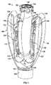
図1~図5は、補綴スペーサーデバイス100およびそのコンポーネントの例示的な一実施形態を示す。図1を参照すると、補綴スペーサーデバイス100は、スペーサー部材102と、複数のパドルまたはアンカー104(たとえば、例示される実施形態の2つ)と、複数のクラスプ106(たとえば、例示される実施形態における2つ)と、第1のカラー108と、第2のカラー110とを備えることができる。図3に最もよく示されるように、アンカー104の第1の端部分112は、スペーサー部材102の第1の端部分114に結合され、そこから延在するものとしてよく、アンカー104の第2の端部分116は、第1のカラー108に結合され得る。第2のカラー110は、スペーサー部材102の第2の端部分118に結合され得る。 1-5 illustrate one exemplary embodiment of a
スペーサー部材102およびアンカー104は、様々な方法で一緒に結合され得る。たとえば、例示される実施形態に示されるように、スペーサー部材102およびアンカー104は、スペーサー部材102とアンカー104とを単一の、単位コンポーネントとして一体形成することによって一緒に結合され得る。これは、たとえば、スペーサー部材102とアンカー104とを、編組または織りニチノールワイヤなどの、編組または織り材料から形成することによってなされ得る。他の実施形態では、スペーサー部材102およびアンカー104は、溶接、留め具、接着剤、および/または結合のための他の手段によって一緒に結合され得る。
図2を参照すると、アンカー104は、ジョイント部分124によって分離される第1の部分120と第2の部分122とを備えることができる。このようにして、アンカー104は、第1の部分120が脚の上側部分に類似し、第2の部分122が脚の下側部分に類似し、ジョイント部分124が脚の膝部分に類似するという点で脚に類似するように構成される。 Referring to FIG. 2,
いくつかの実施形態において、第1の部分120および第2の部分122は、ジョイント部分124によって一緒に結合される別々のコンポーネントであってよい。たとえば、特定の一実施形態において、第1の部分120および第2の部分122は、他にもあるがとりわけ、ジョイント部分124として働く布覆いによって一緒に結合されるプレートまたはシャフトであってよい。 In some embodiments,
アンカー104は、第1のカラー108としたがってアンカー104とをスペーサー部材102に関してスペーサー部材102の第1の端部分114と第2の端部分118との間に延在する長手方向軸に沿って軸方向移動することによって様々な構成の間を移動するように構成され得る。たとえば、アンカー104は、第1のカラー108をアンカー104がピンと張られるようにスペーサー部材102から遠ざかる方向に移動することによって真っ直ぐな、または実質的に真っ直ぐな、または展開された構成で位置決めされ得る。真っ直ぐな構成では、アンカー104のジョイント部分124は、スペーサー部材102の長手方向軸に隣接する(たとえば、図20に示される構成に類似する)。
真っ直ぐな構成から、アンカー104は、第1のカラー108をスペーサー部材102の方へ移動することによって完全に折り畳まれた構成(たとえば、図1)に移動され得る。最初に、第1のカラー108がスペーサー部材102の方へ移動するにつれ、アンカー104はジョイント部分124のところで曲がり、ジョイント部分124は図2~図3に示されるように、スペーサー部材102の長手方向軸に関して半径方向に外向きに、およびスペーサー部材102の第1の端部分114の方へ軸方向に移動する。第1のカラー108がスペーサー部材102の方へ移動し続けると、ジョイント部分124は、図1に示されるように、スペーサー部材102の長手方向軸に関して半径方向に内向きに、およびスペーサー部材102の第2の端部分118の方へ軸方向に移動する。 From a straight configuration,
いくつかの実施形態において、アンカー104の第1の部分120とスペーサー部材102との間に成す角度は、アンカー104が真っ直ぐな構成にあるときに約180度であるものとしてよく(たとえば、図20を参照)、アンカー104の第1の部分120とスペーサー部材102との間に成す角度は、アンカー104が完全に折り畳まれた構成にあるときに約0度であるものとしてよい。アンカー104は、アンカー104の第1の部分120とスペーサー部材102との間に成す角度が約10~170度または約45~135度であり得るように様々な部分的に折り畳まれた構成で位置決めされ得る。 In some embodiments, the angle between
補綴スペーサーデバイス100を、アンカー104が真っ直ぐな、またはほぼ真っ直ぐな構成(たとえば、スペーサー部材102に関して約120~180度)に伸長し得るように構成することには、いくつかの利点があり得る。たとえば、これは、補綴スペーサーデバイス100の半径方向クリンプ外形(radial crimp profile)を縮小することができる。これは、また、自然弁尖を捕らえるより大きな開口部を形成することによって自然弁尖を捕らえるのをより容易にすることができる。それに加えて、比較的狭い、真っ直ぐな構成は、補綴スペーサーデバイス100を送達装置内に位置決めし、および/または取り出すときに補綴スペーサーデバイス100が自然解剖学的構造(たとえば、腱索)内で絡み合うことを防ぐか、またはその可能性を減じることができる。 There may be several advantages to configuring
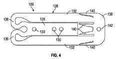
ここでも図2を参照すると、クラスプ106は、取り付け部分126とアーム部分128とを備えることができる。取り付け部分126は、縫合糸、接着剤、留め具(たとえば、プレート129)、溶接、および/または結合するための手段などの、様々な方法でアンカー104の第1の部分120に結合され得る。 Referring again to FIG. 2, clasp 106 can include
アーム部分128は、開放構成(たとえば、図2)と閉鎖構成(図1および図3)との間で取り付け部分126に関して枢動することができる。いくつかの実施形態において、クラスプ106は、閉鎖構成に付勢され得る。開放構成では、取り付け部分126およびアーム部分128は、自然弁尖が取り付け部分126とアーム部分128との間に位置決めされ得るように枢動して互いから遠ざかる。閉鎖構成では、取り付け部分126およびアーム部分128は、互いの方へ枢動し、それによって自然弁尖を取り付け部分126とアーム部分128との間にクランプする。
図4~図5を参照すると、各取り付け部分126(図4~図5に示される1つだけ)は、1つまたは複数の開口部130(たとえば、例示される実施形態では3つ)を備えることができる。開口部130のうちの少なくともいくつかは、取り付け部分126をアンカー104に結合するために使用され得る。たとえば、縫合糸および/または留め具は、クラスプ106の開口部130を通って延在し、またアンカー104を通って延在して取り付け部分126をアンカー104に固定することができる 4-5, each mounting portion 126 (only one shown in FIGS. 4-5) includes one or more openings 130 (eg, three in the illustrated embodiment). be able to. At least some of
アーム部分128の各々は、相隔てて並びスロット134を形成する2つの側部梁132を備えることができる。スロット134は、取り付け部分126を受けるように構成され得る。アーム部分128は、取り付け部分126に結合される固定端部分136と、固定端部分136に対向して配設される自由端部分138とをさらに備え得る。 Each
各アーム部分128の自由端部分138は、バーブ140および/または自然弁尖組織と摩擦係合するための他の手段などの把持要素を備えることができる。把持要素は、自然弁尖組織と係合し、および/または貫通してクラスプ106の取り付け部分126とアーム部分128との間に自然弁尖を保持するのを助けるように構成され得る。 The
自由端部分138は、また、小穴または開口部142を備えることができ、これは自由端部分138を取り付け部分126に関してアーム部分128を枢動させるように構成されている作動機構に結合するために使用できる。クラスプ106を作動機構に結合することに関するさらなる詳細が以下に提示される。
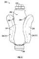
いくつかの実施形態において、クラスプ106は、ニチノール、ステンレス鋼、および/または形状記憶ポリマーなどの形状記憶材料から形成され得る。いくつかの実施形態において、クラスプ106は、材料(たとえば、ニチノール)のフラットシート片を図4に示される構成にレーザー切断し、次いでクラスプ106を図5に示される構成に形状固定することによって形成され得る。 In some embodiments,
このようにしてクラスプ106を形状固定することは、いくつかの利点を提供することができる。たとえば、クラスプ106は、形状固定構成(たとえば、図5)からクラスプ106の半径方向クリンプ外形を短縮する、フラット構成(たとえば、図4)に圧縮され得る。また、これは、補綴スペーサーデバイス100が前進させられてカテーテルシャフト(たとえば、図20を参照)に通されるか、またはその中に取り出されるときにバーブ140がアンカー140の方へ半径方向内向きを指すので、補綴スペーサーデバイス100を送達装置のカテーテルシャフトに関して追跡し取り出す機能も改善する。これは、したがって、クラスプ106がカテーテルシャフトを引っ掛けたり、または裂いたりすることを防ぐか、またはその可能性を低減する。 Form-locking the
それに加えて、図5に示される構成でクラスプ106を形状固定することで、クラスプ106が閉鎖構成にあるときにクラスプ106のクランプ力を高めることができる。これは、アーム部分128が、アンカー104が形状固定構成の方へのアーム部分128のさらなる移動を防ぐのでクラスプ106がアンカー104(たとえば、図3)に取り付けられたときにアーム部分128が達成できる位置を超える第1の位置(たとえば、図5)への取り付け部分126に関して形状固定されるからである。この結果、アーム部分128は、クラスプ106がアンカー104に取り付けられ、閉鎖構成にあるときに予荷重を有する(すなわち、クランプ力がゼロより大きく)なる。したがって、図5の構成でクラスプ106を形状固定することで、閉鎖構成で形状固定されるクラスプと比較してクラスプ106のクランプ力を高めることができる。このようにして、アーム部分128と取り付け部分126との間の接続部は、スプリングヒンジとして機能し、アーム部分128を閉鎖構成に付勢する。 Additionally, by form-locking
クラスプ106の予荷重の大きさは、アーム部分128が取り付け部分126に関して形状固定される角度を調整することによって変えることができる。たとえば、アーム部分128と取り付け部分126との間に成す相対的角度を大きくすると予荷重が増加し、アーム部分128と取り付け部分126との間に成す相対的角度を小さくすると予荷重が減少する。クラスプ106を閉位置に付勢するために、アーム部分128と取り付け部分126との間にバネ(たとえば、トーションバネ)または別のタイプの付勢要素を結合することなどによる、他の技法および機構が使用され得る。さらに代替的に、クラスプ106は、取り付け部分126なしで対応するアンカー104に接続されるものとしてよく、付勢要素は、アンカーに対してクラスプ106を閉鎖構成に付勢するために使用され得る。 The amount of preload on
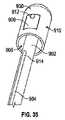
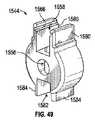
いくつかの実施形態において、第2のカラー110および/またはスペーサー部材102は、第2のカラー110および/またはスペーサー部材102内を血液が流れるのを低減するか、または防ぐように構成されている止血封止部材144を備えることができる。たとえば、いくつかの実施形態において、封止部材144は、図1に示されるように、複数の可撓性フラップ146を備えることができる。フラップ146は、封止構成から開放構成に枢動して送達装置が第2のカラー110を通って延在することを可能にするように構成され得る。送達装置が取り外されるときに、フラップ146は開放構成から封止構成に戻るように構成され得る。 In some embodiments,
図6~図8は、補綴スペーサーデバイス200の例示的な一実施形態を示す。補綴スペーサーデバイス200は、スペーサー部材202と、複数のアンカー204と、複数のクラスプ206と、第1のまたは遠位カラー208と、第2のまたは近位カラー210とを有する。補綴スペーサーデバイス200のこれらのコンポーネントは、補綴スペーサーデバイス100の対応するコンポーネントに実質的に類似するように構成され得る。 6-8 illustrate one exemplary embodiment of a
補綴スペーサーデバイス200は、複数のアンカー伸長部材212も備え得る。アンカー伸長部材212の各々は、遠位カラー208に結合され遠位カラー208から延在する第1のまたは固定端部分214と、固定端部分214に対向して配設される第2のまたは自由端部分216とを有するループ形状構造として構成され得る。アンカー伸長部材212は、アンカー204よりも遠くスペーサー部材202の周上に延在するように構成され得る。たとえば、いくつかの実施形態において、アンカー伸長部材212の各々は、スペーサー部材202の周の約半分に延在するものとしてよく(図7に最もよく示されるように)、アンカー204は、スペーサー部材202の周の半分未満に延在するものとしてよい(図6に最もよく示されるように)。アンカー伸長部材212は、また、スペーサー部材202の外径を超えて横方向に(すなわち、スペーサー部材202の長手方向軸に垂直に)延在するように構成され得る。
アンカー伸長部材212は、補綴スペーサーデバイス200が折り畳まれた構成(たとえば、図6~図8)にあるときにアンカー伸長部材212の自由端部分216がアンカー204のジョイント部分218に隣接して軸方向に、およびアンカー204の第1の部分220と第2の部分222との間で半径方向に配設されるようにさらに構成され得る。
このようにしてアンカー伸長部材212を構成することは、アンカー204単独と比較して広い表面積を提供する。これにより、たとえば、自然弁尖を捕らえて固定することがより容易になり得る。増大した表面積は、また、自然弁尖に対するアンカー204およびアンカー伸長部材212のクランプ力を自然弁尖の比較的広い表面に分散させ、自然弁尖組織をさらに保護することができる。 Configuring
アンカー伸長部材212の表面積が増大することでも、自然弁尖のクランプされていない部分が、スペーサー部材202に対向して、補綴スペーサーデバイス200に隣接する位置で接合して一緒になるように自然弁尖が補綴スペーサーデバイス200にクランプされることを可能にすることができる。これは、たとえば、自然弁尖の封止を改善し、それにより、僧帽弁逆流を防ぐか、またはさらに低減することができる。 The increased surface area of the
図8を参照すると、補綴スペーサーデバイス200は、カバー224も備え得る。いくつかの実施形態において、カバー224は、スペーサー部材202、アンカー204、および/またはアンカー伸長部材212上に配設され得る。カバー224は、血流が補綴スペーサー部材200を通るのを防ぐか、または低減し、および/または自然組織内部成長を促進するように構成され得る。いくつかの実施形態において、カバー224は、PET、ベロア、または他の好適な繊維などの布もしくは織物であってよい。他の実施形態において、織物の代わりに、またはそれに加えて、カバー224は、補綴スペーサーデバイス200に施されるコーティング(たとえば、ポリマー)を含み得る。補綴スペーサーデバイス200は、図6~図7および図12~図13ではカバー224なしで、図8、図11、および図20~図27ではカバー224ありで図示されることに留意されたい。いくつかの実施形態において、カバー224は、所定の長さの時間(たとえば、1日もしくは数日、数週間、または数ヶ月)にわたってスペーサー部材202を通って血液が流れることを可能にするように選択された空隙率を有することができる。時間の経過とともにスペーサーデバイスが内皮化するにつれ、スペーサー部材を通って逆流する血流の量がゆっくりと、徐々に減り、このことにより植え込みの後に左心室にかかる応力の量が減少し得る。所定の期間にわたってスペーサー部材を逆流する血流が通るのを許すカバーのさらなる詳細は、参照により本明細書に組み込まれる2017年9月7日に出願した米国仮出願第62/555,240号において開示される。 Referring to FIG. 8,
図9は、環状スペーサー部材302と、スペーサー部材302の外面を覆う織物カバー(図示せず)と、スペーサー部材302から延在するアンカー304とを備える補綴スペーサーデバイス300の例示的な一実施形態を示す。カバーまたは追加のカバーも、アンカー304の上に延在し得る。各アンカー304の端部は、アンカー304の端部分およびスペーサー部材302のストラットの周りにクリンプされ得るそれぞれのスリーブ306によってスペーサー部材302のそれぞれのストラットに結合され得る。スペーサー部材302のフレーム上に装着されるのは1つまたは複数のバーブもしくは突出部308であってよい。突出部308の自由端は、丸形、先が尖った形状、棘のある形状などを含む様々な形状を含み得る。突出部308は、アンカー304の自由端の下の領域内で自然弁尖を内向きにスペーサー部材302内に押し進めるような形状である、アンカー304により自然弁尖に対して保持力を加えることができる。 FIG. 9 illustrates one exemplary embodiment of a
図10は、補綴スペーサーデバイス400の例示的な一実施形態を示す。補綴スペーサーデバイス400は、環状スペーサー部材402と、スペーサー部材を覆う織物カバー(図示せず)と、スペーサー部材402から延在するアンカー404とを備えることができ、補綴スペーサーデバイス300に類似する構成をとり得る。カバーは、アンカーの外面も覆うものとしてよい。 FIG. 10 shows an exemplary embodiment of a
補綴スペーサーデバイス400のアンカー404は、各アンカー404の自由端のところのカーブがアンカー304に比べて広く、大きい半径を有することを除き補綴スペーサーデバイス300のアンカー304に類似するように構成され得る。そのようなものとして、アンカー404は、アンカー304に比べてスペーサー部材402の比較的広い部分を覆う。これは、たとえば、自然弁尖組織をさらに保護するために、自然弁尖に対するアンカー404のクランプ力を自然弁尖の比較的広い表面に分散させることができる。また、自然弁尖がスペーサー部材402に対向して補綴スペーサーデバイス400に隣接する位置で接合して一緒になるように自然弁尖が補綴スペーサーデバイス400に対してクランプされるので封止を改善することができる。
また、スペーサー部材402のフレーム上に装着されるのは1つまたは複数のバーブもしくは突出部406であってよい。突出部406の自由端は、自然弁尖と係合し、および/または貫通することができる突出部406の範囲を制限するように構成されているストッパー408を備えることができる。 Also mounted on the frame of
補綴スペーサーデバイスに関する追加の詳細は、たとえば、参照により本明細書に組み込まれる、米国特許出願第2016/0331523号および米国仮出願第62/161,688号に見ることができる。 Additional details regarding prosthetic spacer devices can be found, for example, in US Patent Application No. 2016/0331523 and US Provisional Application No. 62/161,688, which are incorporated herein by reference.
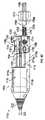
補綴スペーサーデバイス(たとえば、デバイス100、200、300、400)は送達装置に結合され、送達アセンブリを形成することができる。送達装置は、患者の自然心臓弁領域内への補綴スペーサーデバイスの経皮送達、位置決め、および/または固定を行うために使用され得る。 A prosthetic spacer device (eg,
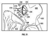
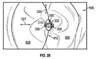
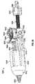
図11~図27は、例示的な送達アセンブリ500およびそのコンポーネントを示す。図11を参照すると、送達アセンブリ500は、補綴スペーサーデバイス200と、送達装置502とを備え得る。送達装置502は、複数のカテーテルと1つまたは複数のカテーテル安定化装置とを備え得る。たとえば、例示される実施形態において、送達装置502は、第1のカテーテル504と、第2のカテーテル506と、第3のカテーテル508と、カテーテル安定化装置510とを備える。第2のカテーテル506は、第1のカテーテル504を同軸上に通って延在し、第3のカテーテル508は、第1のカテーテル504および第2のカテーテル506を同軸上に通って延在する。補綴スペーサーデバイス200は、以下でさらに説明されるように、送達装置502の第3のカテーテル508の遠位端部分に解放可能に結合され得る。 11-27 show an
カテーテル安定化装置510の各々は、手技実行時に患者および送達装置の他のコンポーネントに関して対応するカテーテルを静止状態に保持するために使用され得る。安定化装置510は、共通のテーブルまたは支持プラットフォーム上に位置決めされるものとしてよく、これは次いで手術台上に置かれるものとしてよい。たとえば、カテーテルを患者の血管系内に手動で挿入し、カテーテルの遠位端を患者体内の所望の配置に位置決めした後、医者は、次いで、カテーテルを対応する安定化装置510内に置き、手技実行中に別のカテーテルを操作できるように医者の手を解放するようにできる。カテーテル安定化装置および安定化装置を支持するための支持プラットフォームに関するさらなる詳細は、参照により本明細書に組み込まれる2017年4月28日に出願した米国特許出願第62/491,392号において開示される。 Each
例示される実施形態において、送達アセンブリ500は、たとえば、経中隔送達アプローチを介して補綴スペーサーデバイス200を自然僧帽弁内に植え込むように構成される。他の実施形態において、送達アセンブリ500は、補綴スペーサーデバイス200をヒトの心臓の大動脈弁、三尖弁、または肺動脈弁領域内に植え込むように構成され得る。また、送達アセンブリ500は、経中隔、経大動脈、経血管などを含む、様々な送達方法に合わせて構成され得る。 In the illustrated embodiment,
図13を参照すると、補綴スペーサーデバイス200の第1のまたは遠位カラー208は、ボア226を備え得る。いくつかの実施形態において、ボア226は、図12に最もよく示されるように、送達装置502の作動シャフト512の対応する雄ネジと解放可能に係合するように構成されている雌ネジを備えることができる。 Referring to FIG. 13, first or
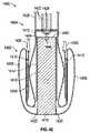
図13を再び参照すると、補綴スペーサーデバイス200の第2のまたは近位カラー210は、遠位カラー208のボア226に軸方向に位置合わせされる中心開口部228を備えることができる。近位カラー210の中心開口部228は、図12に最もよく示されるように、送達装置502の作動シャフト512を摺動可能に受けるように構成され得る。いくつかの実施形態において、近位カラー210および/またはスペーサー部材202は、作動シャフト512が中心開口部228から引き出されるときに中心開口部228を封止するように構成されている封止部材(図示されていないが、ただし、たとえば、図1に示される封止部材144を参照)を有することができる。 Referring again to FIG. 13 , the second or
図13に最もよく示されるように、近位カラー210は、また、複数の隆起部または突出部230と突出部230内に形成された複数のガイド開口部232とを備えることができる。突出部230は、半径方向外向きに延在し、ガイド開口部232に関して周上でオフセット(たとえば、90度)され得る。ガイド開口部232は、中心開口部228から半径方向外向きに配設され得る。近位カラー210の突出部230およびガイド開口部232は、図12に示されるように、送達装置502のカプラー514に解放可能に係合するように構成され得る。 As best shown in FIG. 13,
再び図11を参照すると、上で述べたように、送達装置502は、第1のカテーテル504と第2のカテーテル506とを備えることができる。第1のカテーテル504および第2のカテーテル506は、たとえば、植え込み配置(たとえば、心臓の自然僧帽弁領域)に接近し、および/または第3のカテーテル508を植え込み配置のところに位置決めするために使用され得る。 Referring again to FIG. 11, the
第1のカテーテル504および第2のカテーテル506は、それぞれ、ハンドル517、519から延在する第1のシースもしくはシャフト516および第2のシースもしくはシャフト518を備えることができる。第1のカテーテル504および第2のカテーテル506は、シース516、518が操縦可能であるように構成され得る。たとえば、図示されていないが、第2のカテーテル506は、1つまたは複数のプルワイヤと、1つまたは複数の可撓性の、軸方向に非圧縮性であるプルワイヤスリーブ(たとえば、螺旋コイル)とを備えることができる。プルワイヤおよびスリーブは、シャフト518の一部を通って延在することができ、スリーブは、シャフト518に関して自由に移動することができるが、これは参照により本明細書に組み込まれる米国特許出願公開第2016/0158497号においてさらに説明されるとおりである。これは、たとえば、植え込みカテーテル(たとえば、第3のカテーテル508)の遠位端部分およびしたがって補綴スペーサーデバイスを1つまたは複数の他の方向(たとえば、下側方向/上側方向)で僧帽弁に関して同軸にさらに保ちながら、シャフト518の操縦可能な遠位端部分518aが1つまたは複数の方向に(たとえば、後内側交連と前外側交連との間の自然僧帽弁尖の間の接合線の「C字」形を辿る内側/外側および/または前側/後側方向に)偏向され、移動され、および/または回転されることを可能にすることができる。 The
第1のカテーテル504に関する追加の詳細は、たとえば、参照により本明細書に組み込まれる、2017年10月27日に出願した米国特許出願第15/796,436号に見ることができる。第2のカテーテル506に関する追加の詳細は、たとえば、米国特許出願公開第2016/0158497号に見ることができる。 Additional details regarding
なおも図11を参照すると、送達装置502は、上で述べたように、第3のカテーテル508を備えることもできる。第3のカテーテル508は、たとえば、以下でさらに説明されるように、植え込み配置で補綴スペーサーデバイス200を送達し、操作し、位置決めし、および/または配備するために使用できる。 Still referring to FIG. 11, the
図15を参照すると、第3のカテーテル508は、内側または作動シャフト512と、カプラー514と、外側シャフト520と、ハンドル522(概略図に示される)と、クラスプ制御部材524とを備えることができる。外側シャフト520の近位端部分520aは、ハンドル522に結合されハンドル522から遠位に延在するものとしてよく、外側シャフト520の遠位端部分520bは、カプラー514に結合されるものとしてよい。作動シャフト512の近位端部分512aは、作動ノブ526に結合され得る。作動シャフト512は、ノブ526(概略として示される)から遠位に、ハンドル522を通り、外側シャフト520を通り、カプラー514を通って延在し得る。作動シャフト512は、外側シャフト520およびハンドル522に関して(たとえば、軸方向におよび/または回転可能に)移動可能であるものとしてよい。クラスプ制御部材524は、ハンドル522および外側シャフト520を通って延在し、ハンドル522および外側シャフト520に関して軸方向に移動可能であるものとしてよい。クラスプ制御部材524は、また、作動シャフト512に関して軸方向に移動可能であるものとしてよい。 Referring to FIG. 15, a
いくつかの実施形態において、第3のカテーテル508の外側シャフト520は、操縦可能であるように構成され得る。たとえば、図示されていないが、第3のカテーテル508は、プルワイヤと可撓性の、軸方向に非圧縮性であるプルワイヤスリーブ(たとえば、螺旋コイル)とを備えることができる。 In some embodiments, the
図12~図13に最もよく示されるように、第3のカテーテル508の作動シャフト512は、補綴スペーサーデバイス200の遠位カラー208に解放可能に結合され得る。たとえば、いくつかの実施形態において、作動シャフト512の遠位端部分512bは、補綴スペーサーデバイス200のボア226の雌ネジと解放可能に係合するように構成されている雄ネジを備えることができる。そのようなものとして、補綴スペーサーデバイス200の遠位カラー208に関して作動シャフト512を第1の方向に(たとえば、時計回りに)回転させることで、作動シャフト512を遠位カラー208に解放可能に固定する。補綴スペーサーデバイス200の遠位カラー208に関して作動シャフト512を第2の方向に(たとえば、反時計回りに)回転させることで、作動シャフト512を遠位カラー208から解放する。 As best shown in FIGS. 12-13,
次に図12~図14を参照すると、第3のカテーテル508のカプラー514は、補綴スペーサーデバイス200の近位カラー210に解放可能に結合され得る。たとえば、いくつかの実施形態において、カプラー514は、複数の可撓性アーム528と、複数の安定化装置部材530とを備えることができる。可撓性アーム528は、開口532と、ポート533(図13)と、小穴534(図14)とを備えることができる。 12-14, the
可撓性アーム528は、第1のまたは解放構成(図13)と第2のまたは結合構成(図12および図14)との間で枢動するように構成され得る。第1の構成において、可撓性アーム528は、安定化装置部材530に関して半径方向外向きに延在する。第2の構成において、可撓性アーム528は、図14に最もよく示されるように、安定化装置部材530と軸方向に平行に延在し、小穴534は半径方向に重なり合う。可撓性アーム528は、第1の構成に付勢されるように構成(たとえば、形状固定)され得る。
補綴スペーサーデバイス200は、カプラー514の安定化装置部材530を補綴スペーサーデバイス200のガイド開口部232内に挿入することによってカプラー514に解放可能に結合され得る。カプラー514の可撓性アーム528は、第1の構成から第2の構成に半径方向内向きに枢動させられるものとしてよく、それにより、補綴スペーサーデバイス200の突出部230は可撓性アーム528の開口532内に半径方向に延在する。可撓性アーム528は、作動シャフト512の遠位端部分512bを小穴534の開口部536に挿入して通すことによって第2の構成に保持されるものとしてよく、これは、可撓性アーム528が第2の構成から第1の構成に半径方向外向きに枢動することを防ぎ、それによって補綴スペーサーデバイス200をカプラー514に解放可能に結合する。
補綴スペーサーデバイス200は、作動シャフト512の遠位端部分512bが小穴534の開口部536から抜けるようにカプラー514に関して作動シャフト512を近位に引っ込めることによってカプラー514から解放され得る。これは、可撓性アーム528が第2の構成から第1の構成に半径方向外向きに枢動することを可能にし、それにより、補綴スペーサーデバイス200の突出部230を可撓性アーム528の開口532から引き抜く。安定化装置部材530は、可撓性アーム528が解放される間および解放された後に補綴スペーサーデバイス200のガイド開口部232内に挿入されたままにすることができる。これは、たとえば、可撓性アーム528が解放される間に補綴スペーサーデバイス200が移動する(たとえば、シフトするおよび/または揺れ動く)のを防ぐことができる。次いで、安定化装置部材530は、補綴スペーサーデバイス200に関してカプラー514を近位に引っ込めることによって補綴スペーサーデバイス200のガイド開口部232から引き抜かれ、それによって、補綴スペーサーデバイス200をカプラー514から解放することができる。
図15を参照すると、第3のカテーテル508の外側シャフト520は、ハンドル522に結合される、近位端部分520aと、カプラー514に結合される、遠位端部分520bとの間で軸方向に延在する伸長シャフトであるものとしてよい。外側シャフト520は、また、近位端部分520aと遠位端部分520bとの間に配設される中間部分520cも備え得る。 15,
図16を参照すると、外側シャフト520は、作動シャフト内腔538を含む、複数の軸方向に延在する内腔と、複数の制御部材内腔540(たとえば、例示される実施形態では4つ)とを備え得る。いくつかの実施形態において、外側シャフト520は、4つより多い(たとえば、6つ)または少ない(たとえば、2つ)制御部材内腔540を備えることができる。 16, the
作動シャフト内腔538は、作動シャフト512を受けるように構成されるものとしてよく、制御部材内腔540は、1つまたは複数のクラスプ制御部材524を受けるように構成されるものとしてよい。内腔538、540は、また、作動シャフト512およびクラスプ制御部材524がそれぞれの内腔538、540に関して移動可能であり得る(たとえば、軸方向におよび/または回転可能に)ように構成されてもよい。特定の実施形態において、内腔538、540は、内腔538、540内の摩擦を減じるように構成されているライナーまたはコーティングを備えることができる。たとえば、内腔538、540は、PTFEを含むライナーを備えることができる。
なおも図15~図16を参照すると、外側シャフト520は、金属およびポリマーを含む、様々な材料から形成され得る。たとえば、特定の一実施形態において、近位端部分520aはステンレス鋼を備えることができ、遠位端部分520bおよび中間部分520cはPEBA(たとえば、PEBAX(登録商標))を備えることができる。外側シャフト520は、部分520a、520b、および520c上に還流するポリマーなどの、外側被覆またはコーティングも備えることができる。 Still referring to FIGS. 15-16,
外側シャフト520は、内腔538、540から半径方向外向きに配設される1つまたは複数のコイル部分542を備えることができる。たとえば、特定の一実施形態において、外側シャフト520は、第1のコイル542aと、第2のコイル542bと、第3のコイル542cとを備えることができる。第1のコイル542aは半径方向に最も外側のコイルであってよく、第3のコイル542cは半径方向に最も内側のコイルであってよく、第2のコイル542bは第1のコイル542aと第3のコイル542cとの間に半径方向に配設されるものとしてよい。
コイル部分542は、様々な材料および/または構成を備え得る。たとえば、コイル部分542は、ステンレス鋼から形成され得る。特定の一実施形態において、第1のコイル542aおよび第3のコイル542cは左巻き構成で巻かれたステンレス鋼コイルを含み、第2のコイル542bは右巻き構成で巻かれたステンレス鋼コイルを含む。
コイル部分542は、また、様々なピッチを備え得る。コイル部分542の1つまたは複数のコイル部分のピッチは、1つまたは複数の他のコイル部分542のピッチと同じか、または異なっていてもよい。特定の一実施形態において、第1のコイル542aおよび第2のコイル542bは、第1のピッチ(たとえば、0.74インチ)を有することができ、第3のコイルは、第2のピッチ(たとえば、0.14インチ)を備えることができる。
外側シャフト520は、第3のコイル542cから半径方向内向きに配設される結合層544も備え得る。結合層544は、PEBA(たとえば、PEBAX(登録商標)などの、ポリマーを含む、様々な材料から形成され得る。
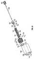
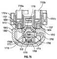
図17~図19に示されるように、第3のカテーテル508のハンドル522は、ハウジング546と、作動係止機構548と、クラスプ制御機構550と、フラッシング機構552とを備えることができる。図17を参照すると、ハウジング546の遠位端部分は、外側シャフト520の近位端部分520aに結合され得る。作動係止機構548、クラスプ制御機構550、およびフラッシング機構552は、ハウジング546の近位端に結合され得る。作動係止機構548は、作動シャフト512の位置をハウジング546および外側シャフト520に関して選択的に係止するように構成され得る。クラスプ制御機構550は、クラスプ制御部材524の近位端部分にも結合されるものとしてよく、ハンドル522に関してクラスプ制御部材524を固定し、外側シャフト520および作動シャフト512に関してクラスプ制御部材524を移動するように構成され得る。フラッシング機構552は、外側シャフト520を患者の血管系内に挿入する前に外側シャフト520を(たとえば、生理食塩水で)フラッシングするように構成され得る。 As shown in FIGS. 17-19, the
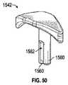
図18~図19に最もよく示されるように、ハンドル522のハウジング546は、本体部554と、本体部554の遠位端部分に結合されるノーズ部分556とを備えることができる。本体部554およびノーズ部分556は、留め具558および/またはピン560(たとえば、例示される実施形態に示されるような)、接着剤、および/または他の結合手段を含む、様々な方式で一緒に結合され得る。ハウジング546は、ポリマー(たとえば、ポリカーボネート)を含む、様々な材料から形成され得る。 As best shown in FIGS. 18-19,
ハウジング546の本体部554は、作動シャフト内腔562、制御部材内腔564(図19)、および作動シャフト内腔562(図18)に流体的に接続されるフラッシング内腔566を含む、複数の内腔を備えることができる。図19に最もよく示されるように、本体部554は、作動チューブ568ならびに作動シャフト内腔562および制御部材内腔564内にそれぞれ少なくとも部分的に配設される制御部材チューブ570を含む、複数のチューブ(たとえば、ハイポチューブ)も備え得る。チューブ568、570は、それぞれ内腔562、564に関して軸方向に移動可能(たとえば、摺動可能)であるものとしてよい。
作動チューブ568の近位端は、本体部554から近位に延在し、ノブ526と、作動シャフト512の近位端部分512aとに結合され得る。制御部材チューブ570の近位端は、本体部554から近位に延在し、クラスプ制御機構550と、クラスプ制御部材524とに結合され得る。 A proximal end of
チューブ568、570の遠位端は、ハウジング546に関してチューブ568、570の軸方向移動を制限するためにストッパーと係合するように構成されているフランジ572、574を備えることができる。たとえば、フランジ572、574は、本体部554のそれぞれの表面(たとえば、リップ部)と接触して、チューブ568、570がそれぞれ内腔562、564の近位端から完全に抜けてしまうのを防ぐように構成され得る。 The distal ends of
作動チューブ568は、作動シャフト512の近位端部分を受け、その近位端部分に結合されるように構成され得る。制御部材チューブ570は、以下でさらに説明されるように、クラスプ制御機構550の一部を受けるように構成され得る。チューブ568、570は、ポリマーおよび金属(たとえば、ステンレス鋼)を含む、様々な材料から形成され得る。
いくつかの実施形態において、本体部554は、内腔を通り、シャフトおよび/またはチューブの周りを流れる血液漏出を防ぐか、または低減するように構成されている複数のシール部材576(たとえば、Oリング)を備えることができる。シール部材は、たとえば、留め具578(たとえば、中空係止またはソケットジャム止めネジ)によって、本体部554に関して固定され得る。 In some embodiments, the
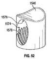
図19に最もよく示されるように、ハウジング546のノーズ部分556は、作動シャフト内腔580および制御部材内腔582を含む、複数の内腔を備えることができる。ノーズ部分556の作動シャフト内腔580は、本体部554の作動シャフト内腔562と同軸上に延在し得る。ノーズ部分556の制御部材内腔582の近位端は、ノーズ部分556の近位端で本体部554の制御部材内腔564と位置合わせされ得る(すなわち、内腔582、564は同じ平面内にある)。制御部材内腔582は、ある角度(すなわち、本体部554の制御部材内腔564に関する)で近位端から互いの方へ延在するものとしてよく、制御部材内腔582の遠位端は、ノーズ部分556の遠位端の近くの配置でノーズ部分556の作動シャフト内腔580と交差することができる。言い換えると、内腔582の近位端は、カテーテルの長手方向軸に平行な第1の平面(すなわち、本体部554の制御部材内腔564の平面)内にあり、内腔582の遠位端は、カテーテルの長手方向軸に平行な第2の平面(すなわち、本体部554の作動シャフト内腔562の平面)内にある。 As best shown in FIG. 19,
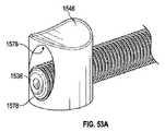
図18に最もよく示されるように、ノーズ部分556の作動シャフト内腔580は、外側シャフト520の近位端部分を受けるように構成され得る。外側シャフト520の近位端部分は、接着剤、留め具、摩擦嵌め、および/または他の結合手段などによる様々な方法でノーズ部分556に結合され得る。 As best shown in FIG. 18,
なおも図18を参照すると、ハンドル522の作動係止機構548は、ハウジング546の本体部554の近位端部分と、作動チューブ568とに結合され得る。作動係止機構548は、作動チューブ568とハウジング546との間の相対的移動を選択的に制御するように構成され得る。これは、延いては、作動シャフト512(作動チューブ568に結合される)と外側シャフト520(ハウジング546のノーズ部分556に結合される)との間の相対的移動を選択的に制御する。 Still referring to FIG. 18, an
いくつかの実施形態において、作動係止機構548は係止構成を備え、これは、作動チューブ568とハウジング546との間の相対的移動を防ぐ、係止構成と、作動チューブ568とハウジング546との間の相対的移動を可能にする、解放構成とを備えることができる。いくつかの実施形態において、作動係止機構548は、作動チューブ568とハウジング546との間の相対的移動を可能にする1つまたは複数の中間構成(すなわち、係止および解放構成に加えて)を含むように構成されるものとしてよいが、相対的移動を引き起こすのに必要な力は、作動係止機構が解放構成にあるときに比べて大きい。 In some embodiments, the
例示される実施形態の図18に示されるように、作動係止機構548は、ロック(たとえば、Tuohy-Borstアダプタ)584とカプラー(たとえば、メスルアーカプラー)586とを備えることができる。カプラー586は、ロック584の遠位端に取り付けられ、ハウジング546の本体部554の近位端に結合され得る。作動チューブ568は、ロック584およびカプラー586を通して同軸上で延在し得る。そのようなものとして、ロック584のノブ588を第1の方向(たとえば、時計回り)に回転させることで、作動チューブ568上のロック584の摩擦係合を高め、それにより、作動チューブ568とハウジング546との間の相対的移動をより難しくするか、または完全に防ぐことができる。ロック584のノブ588を第2の方向(たとえば、反時計回り)に回転させることで、作動チューブ568上のロック584の摩擦係合を減じて、それにより、作動チューブ568とハウジング546との間の相対的移動をしやすくすることができる。 As shown in FIG. 18 of the illustrated embodiment, the
他の実施形態において、作動係止機構548は、作動チューブ568とハウジング546との間の相対的移動を防ぐように構成されている他の構成を含むことができる。たとえば、作動係止機構548は、弁のプランジャ部分が作動チューブ568と選択的に係合するストップコック弁に類似する構成のロックを備えることができる。 In other embodiments,
いくつかの実施形態において、作動係止機構548は、解放部材(たとえば、止めネジまたはピン)を備えることができる。解放部材は、ハウジング546内に延在することができ、作動チューブ568と選択的に係合することができる。解放部材が作動チューブ568と係合されたときに(たとえば、解放部材をハウジング546内に挿入し、作動チューブ568と接触させることによって)、解放部材は、たとえば、作動チューブ568、およびしたがって、(たとえば、アンカー204を作動させたときに)作動シャフト512がそれぞれの内腔568、580から完全に抜けるのを防ぐことができる。解放部材が作動チューブ568から解放されるときに(たとえば、ハウジング546から引き抜き、および/または作動チューブ546との接触から外すことによって)、作動チューブ568、およびしたがって、作動シャフト512は、それぞれの内腔568、580から完全に引き抜かれ得る(たとえば、補綴スペーサーデバイス200を送達装置502から解放したときに)。 In some embodiments, the
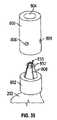
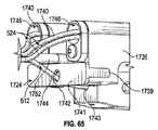
クラスプ制御機構550は、アクチュエータ部材590と、1つまたは複数の係止部材592(たとえば、例示される実施形態では2つ)を備えることができる。アクチュエータ部材590の遠位端部分は、制御部材チューブ570に結合されてよく、これは、図18に最もよく示されるように、ハウジング546の本体部554の近位端から延在する。係止部材592は、アクチュエータ部材590の近位端部分に結合され得る。 The
例示される実施形態に示されるように、アクチュエータ部材590は、任意選択で、第1の側部594と、接続ピン598によって第1の側部594に選択的に結合される第2の側部596とを備えることができる。アクチュエータ部材590は、第1の側部594および第2の側部596が、接続ピン598が第1の側部594および第2の側部596に挿通されたときに一緒に移動するように構成され得る。接続ピン598が引き抜かれるときに、第1の側部594および第2の側部596は互いに関して移動され得る。これは、クラスプ制御部材524(係止部材592によって第1の側部594および第2の側部596に解放可能に結合される)が個別に作動されることを可能にし得る。 As shown in the illustrated embodiment, the
第1の側部594と第2の側部596との間の接続は、第1の側部594および第2の側部596が軸方向に(すなわち、近位および遠位に)移動し得るが、接続ピン598が引き抜かれたときには互いに関して回転可能に移動し得ないように構成される。これは、たとえば、第1の側部594をキースロットまたは溝を備えるように構成し、第2の側部596を第1の側部594のキースロットまたは溝に対応するキー突出部または舌部を備えるように構成することによって達成され得る。これは、たとえば、クラスプ制御部材524が外側シャフト520に関して捻ることを防ぐか、またはその可能性を減じることができる。 The connection between the
第1の側部594および第2の側部596は、軸方向に延在する内腔501を備えることができる。内腔501の遠位端は、制御部材チューブ570の近位端部分を受けるように構成され得る。内腔501の近位端は、係止部材592の一部を受けるように構成され得る。上で述べたように、クラスプ制御部材524の近位端部分は、それぞれの係止部材592を通って延在する。
係止部材592は、クラスプ制御部材524とアクチュエータ部材590のそれぞれの第1の側部594または第2の側部596との間の相対的移動を選択的に制御するように構成され得る。係止部材592は、クラスプ制御部材524とそれぞれの第1の側部594または第2の側部596との間の相対的移動を妨げる、係止構成と、クラスプ制御部材524とそれぞれの第1の側部594または第2の側部596との間の相対的移動を可能にする、解放構成とを備えることができる。いくつかの実施形態において、係止部材592は、また、クラスプ制御部材524とそれぞれの第1の側部594または第2の側部596との間の相対的移動を可能にする1つまたは複数の中間構成(すなわち、係止および解放構成に加えて)を備え得るが、相対的移動を引き起こすのに必要な力は、係止部材592が解放構成にあるときに比べて大きい。 Locking
例示される実施形態において示されるように、係止部材592は、ストップコック弁と類似の構成を取ることができる。したがって、ノブ503を第1の方向(たとえば、時計回り)に回転させることで、クラスプ制御部材524上の係止部材592の間の摩擦係合を高め、クラスプ制御部材524とそれぞれの第1の側部594または第2の側部596との間の相対的移動をより難しくするか、または完全に防ぐことができる。ノブ503を第2の方向(たとえば、時計回り)に回転させることで、クラスプ制御部材524上の係止部材592の間の摩擦係合を減じて、クラスプ制御部材524とそれぞれの第1の側部594または第2の側部596との間の相対的移動をしやすくすることができる。他の実施形態において、係止部材592は、クラスプ制御部材524上の係止部材592の間の相対的移動を防ぐように構成されている他の構成を含むことができる。 As shown in the illustrated embodiment, locking
フラッシング機構552は、フラッシングチューブ505と弁507(たとえば、ストップコック弁)とを備えることができる。フラッシングチューブ505の遠位端は、フラッシング内腔566に結合され、流体的に連通し、したがって本体部554の作動シャフト内腔562と流体的に連通することができる。フラッシングチューブ505の近位端は、弁507に結合され得る。このようにして、フラッシング機構552は、外側シャフト520を患者の血管系内に挿入する前に外側シャフト520を(たとえば、生理食塩水で)フラッシングするように構成され得る。
クラスプ制御部材524は、以下でさらに説明されるように、クラスプ206の構成を操作するように構成され得る。図15に最もよく示されるように、クラスプ制御部材524の各々は、縫合糸(たとえば、ワイヤまたは糸)ループとして構成され得る。クラスプ制御部材524の近位端部分は、クラスプ制御機構550の近位端部分から近位に延在するものとしてよく、クラスプ制御機構550の係止部材592に解放可能に結合されるものとしてよい。
係止部材592から、クラスプ制御部材524はクラスプ制御機構550の内腔501を通り、制御部材チューブ570を通り、ハンドル522の制御部材内腔564、582を通り、外側シャフト520の制御部材内腔540を通って遠位に延在するループを形成することができる。クラスプ制御部材524は、内腔540から半径方向外向きに、たとえば、カプラー514のポート533(図13)を通って延在し得る。次いで、クラスプ制御部材524は、クラスプ206の開口部234(たとえば、補綴スペーサーデバイス100の開口部142に類似する)を通って延在することができる。次いで、クラスプ制御部材524は、カプラー514へ近位に戻り、カプラー514のポート533を通って半径方向内向きに、次いで外側シャフト520およびハンドル522を通って近位に、クラスプ制御機構550の係止部材592に延在することができる。 From locking
図15において、クラスプ制御部材524は、弛んでいるように示され、クラスプ206は、クラスプ206の開口部234を通って延在するクラスプ制御部材524を例示するために部分的に開いている。しかしながら、通常はクラスプ制御部材524が弛んでいるときに、クラスプ206は、閉鎖構成にある。 In FIG. 15
例示される実施形態に示されるように、クラスプ制御部材524の各々は、外側シャフト520の複数の制御部材内腔540を通って延在するものとしてよい。たとえば、クラスプ制御部材524の各々は、内腔540のうちの2つを通ってループするものとしよい。他の実施形態では、クラスプ制御部材524の各々は、単一の制御部材内腔540内に配設され得る。さらに他の実施形態では、複数のクラスプ制御部材524が、単一の制御部材内腔540内に配設され得る。 As shown in the illustrated embodiment, each of the
クラスプ制御部材524がクラスプ206に結合された状態で、クラスプ制御機構550は、開放構成と閉鎖構成との間でクラスプ206を作動させるために使用され得る。クラスプ206は、アクチュエータ部材590をノブ526およびハウジング546に関して近位に移動することによって開くことができる。これは、クラスプ制御部材524の引張力を高め、クラスプ206を閉鎖構成から開放構成に移動させる。クラスプ206は、アクチュエータ部材590をノブ526およびハウジング546に関して遠位に移動することによって閉じることができる。これは、クラスプ制御部材524にかかる引張力を減じ、クラスプ206を開放構成から閉鎖構成に移動することを可能にする。クラスプ206は、接続ピン598を取り外し、第1の側部594または第2の側部596を互いに、ノブ526に、およびハウジング546に関して移動することによって個別に作動させることができる。 With
ハンドル522が図17~図18に最もよく示されるように組み立てられたときに、作動シャフト512は、ノブ526から遠位に、作動チューブ568を通り、ハウジング546の作動内腔562、580を通り、外側シャフト520の作動シャフト内腔538を通り、カプラー514を通って遠位に延在し得る。 When handle 522 is assembled as best shown in FIGS. 17-18,
図20~図27は、送達アセンブリ500が、たとえば、経中隔送達アプローチを使用して補綴スペーサーデバイス200を心臓602の自然僧帽弁600内に植え込むために使用されることを示す。図示されていないが、ガイドワイヤが導入器シースを通して患者の血管系(たとえば、大腿静脈)内に挿入され得る。ガイドワイヤは、前進させられて大腿静脈を通り、下大静脈を通り、右心房内に入り、心房中隔604を通り(たとえば、卵円窩を経由して)、左心房606内に送り込まれ得る。第1のカテーテル504の第1のシース516は、第1のシース516の遠位端部分が左心房606内に配設されるようにガイドワイヤ上で前進させられるものとしてよく、これは図20に最もよく示される。 20-27 show that
補綴スペーサーデバイス200が第3のカテーテル508に結合され(たとえば、図12に示されるように)、半径方向に圧縮され、送達構成で構成されている場合、補綴スペーサーデバイス200は、第2のカテーテル506の第2のシース518内に装填され、補綴スペーサーデバイス200を送達構成に保持することができる。このようにして、第2のシース518の遠位端部分は補綴インプラント200用の送達カプセルとしての機能を果たす。いくつかの実施形態において、半径方向に圧縮された送達構成は、軸方向伸長構成(たとえば、図20に示される構成に類似する)であってよい。他の実施形態において、半径方向に圧縮された送達構成は、軸方向短縮構成(たとえば、図22に示される構成に類似する)であってよい。次いで、第2のカテーテル506は補綴スペーサーデバイス200および第3のカテーテル508とともに、第2のシース518の遠位端部分が、図20に示されるように、第1のシース516の遠位端部分から外向きに延在し、左心房606内に配設されるまで、一緒に前進させられ第1のカテーテル504に通されるものとしてよい。 When the
図20に示されるように、補綴スペーサーデバイス200は、第2のシース518に関して第3のカテーテル508の外側シャフト520および作動シャフト512を遠位に前進させ、および/または外側シャフト520および作動シャフト512に関して第2のシース518を引っ込めることによって第2のシース518から前進させられるものとしてよく、それにより、アンカー204を強制的に第2のシース518から押し進めることができる。第2のシース518から露出した後、アンカー204は、第3のカテーテル508の外側シャフト520に関して第3のカテーテル508の作動シャフト512を引っ込めること、および/または作動シャフト512に関して外側シャフト520を前進させ、アンカー204を図20に示される構成から図21に示される部分的に折り畳まれた構成に、次いで図22に示される完全に折り畳まれた構成になるように曲げることによって折り畳まれ得る。これは、たとえば、作動係止機構548を解放構成にし(たとえば、ノブ588をハンドル522に関して反時計回りに回転させることによって)、次いで、ハウジング546に関してノブ526を近位に移動することによって達成され得る。手技の任意の時点において、医者は、作動シャフト512および外側シャフト520の相対的位置、およびしたがって、アンカー204の位置を、作動係止機構548を作動させることによって係止することができる。 As shown in FIG. 20,
次いで、補綴スペーサーデバイス200は、図22に示されるように、第2のカテーテル506の第2のシース518を操作する(たとえば、操縦するおよび/または曲げる)ことによって自然僧帽弁600に関して同軸上に位置決めされ得る。第2のシース518の曲率は、遠位操縦可能セクション518aが操縦可能セクション518aから近位に延在するセクション518bに関して約90度の角度を成すように延在するように調整され得る(たとえば、操縦機構により)。都合のよいことに、これは、自然僧帽弁によって定められる平面に実質的に垂直である軸に沿って操縦可能遠位セクション518aと補綴スペーサーデバイス200とを位置決めする。別の言い方をすると、操縦可能遠位セクション518aと補綴スペーサーデバイス200とを通って延在する軸は、自然僧帽弁の流路と同軸であるか、または実質的に平行であるということである。 The
第1のカテーテル504の第1のシース516および左心房606に関して第2のカテーテル506の第2のシース518および第3のカテーテル508の外側シャフト520を(たとえば、矢印521によって示される方向に)引っ込めるか、または前進させると、第3のカテーテル508の外側シャフト520および補綴スペーサーデバイス200は自然弁尖608に関して内側および外側方向に(たとえば、図28の矢印523によって示される方向に)移動する。第2のシース518および外側シャフト520が前進させられ、および/または引っ込められると、上側/下側方向(たとえば、図22に示される方位の上/下)への自然僧帽弁に関する補綴スペーサーデバイス200の位置決めは、少なくとも実質的に一定のままであり、および/または第2のシース518は第2のカテーテル506の操縦機構の構成により「ホイップ」しないが、これは上で説明される。第1のカテーテル504の第1のシース516および左心房606に関して第2のカテーテル506の第2のシース518を(たとえば、図22の矢印525によって示される方向に)回転させる(「トルクを与える」とも称され得る)と、第3のカテーテル508の外側シャフト520および補綴スペーサーデバイス200は前側/後側方向に(たとえば、図28の矢印527によって示される方向に)枢動する。補綴スペーサーデバイス200は、また、アンカー204を自然僧帽弁600の自然弁尖608と位置合わせするために自然僧帽弁600に関して(たとえば、ハウジング546を回転させることによって)回転させられ得る。上側/下側方向(たとえば、図22に示される方位の上/下)への自然僧帽弁に関する補綴スペーサーデバイス200の位置決めは、第2のカテーテル506の第2のシースに関して第3のカテーテル508の外側シャフト520を引っ込める/前進させることによって調整され得る。したがって、開示される送達装置の一利点は、補綴スペーサーデバイスの位置決めが3つの方向(すなわち、内側/外側、前側/後側、および上側/下側方向)に独立して調整できることである。たとえば、補綴スペーサーデバイスが内側/外側方向に移動するように送達装置を作動させても、前側/後側方向または上側/下側方向への補綴スペーサーデバイスの位置決めに影響しない。したがって、送達装置502の3方向および/または独立操縦性は、医師が補綴スペーサーデバイス200を比較的高速でおよび/または容易な方式で自然弁尖に関する所望の植え込み位置に(たとえば、自然弁尖の接合線612(図28)の中心の近くのA2/P2位置に)正確におよび/または精密に位置決めすることを可能にする。 Retract
次いで、補綴スペーサーデバイス200のアンカー204は、ハウジング546に関して遠位にノブ526を移動することによって図23に示される構成になるように部分的に開かれる(すなわち、スペーサー部材202に関して半径方向外向きに移動される)ものとしてよい。次いで、補綴スペーサーデバイス200は、第2のカテーテル506に関して第3のカテーテル508のハンドル522を前進させることによって、前進させられて自然僧帽弁600の輪に通され、少なくとも部分的に左心室610に送り込まれるものとしてよい。次いで、アンカー204が自然弁尖608の心室部分の背後(たとえば、A2/P2位置)に位置決めされ、スペーサー部材202は、自然弁尖608の心房側に配設されるように補綴スペーサーデバイス200は、部分的に引っ込められる。代替的に、補綴スペーサーデバイス200は完全に折り畳まれた構成で(図22に示されるように)、前進させられて自然弁に通され、その後アンカー204は開かれ得る。
この構成では、自然弁尖608は、クラスプ206で自然弁尖を捕らえることによってアンカー204に関して固定され得る。自然弁尖608は、アクチュエータ部材590を作動させることによって同時にまたは別々に捕らえられ得る。たとえば、図24は、別個の弁尖捕獲を示す。これは、接続ピン598をアクチュエータ部材590から取り外し、第1の側部594または第2の側部596を互いに、ノブ526に、およびハウジング546に関して移動することによって達成され得る。第1の側部594または第2の側部596をノブ526およびハウジング546に関して遠位に移動することで、自然弁尖608上のクラスプ206が閉じる(たとえば、図24に例示されるような左クラスプ206によって示されるように)。第1の側部594または第2の側部596をノブ526およびハウジング546に関して近位に移動することで、クラスプ206が開く(たとえば、図24に例示されるような右クラスプ206によって示されるように)。クラスプ206が閉じられた後、医師は、クラスプ206を再び開き、クラスプ206の位置決めを調整することができる。 In this configuration,
クラスプ206が再び開くと、クラスプ206は、最初に、クラスプ206がスペーサー部材202と(たとえば、図23に示されるように)接触するまでスペーサー部材202の方へ半径方向内向きに(図24の右クラスプ206で示されるように)移動する。いくつかの場合において、クラスプ206のバーブ236は、クラスプ206が再び開かれるときに自然弁尖608を保持し、スペーサー部材202の方へ自然弁尖608を引くものとしてよい。クラスプ206がスペーサー部材202と接触した後、クラスプ制御部材524をさらに引っ張ることで、クラスプ206はスペーサー部材202に関してわずかに近位に移動する(そしてアンカー204をわずかに広げる)。クラスプ206が近位に移動することで、たとえば、バーブ236は自然弁尖608から引き出すことができ、これは補綴スペーサーデバイス200の再位置決めおよび/または取り出しを円滑にすることができる。 When clasp 206 reopens, clasp 206 initially moves radially inward toward spacer member 202 (see FIG. 24) until
自然弁尖608の両方がクラスプ206内に固定される場合、医師は、ノブ526をハウジング546に関して近位に移動することができる。これは、図25に示されるように、アンカー204を引き、したがって自然弁尖608をスペーサー部材202に対して半径方向内向きに引く。次いで、医師は、位置決めおよび/または逆流の低減を観察することができる。再位置決めまたは取り外しが望まれる場合、医師は、アンカー204および/またはクラスプ206を再び開くことができる。 With both
所望の位置決めおよび/または逆流の低減が達成された後、医師は補綴スペーサーデバイス200を送達装置502から解放することができる。クラスプ206は、クラスプ制御部材524を係止部材592から解放し、クラスプ制御部材524をクラスプ206の開口部234から螺合解除することによって送達装置502から解放され得る。補綴スペーサーデバイス200の遠位カラー208は、作動シャフト512がボア226から抜けるようにハウジング546に関してノブ526を第2の方向に回転させることによって送達装置502から解放され得る。次いで、作動シャフト512は、ハウジング546に関してノブ526を近位に引くことによって補綴スペーサーデバイス200を通して近位に引っ込められ得る。補綴スペーサーデバイス200の近位カラー210は、作動シャフト512の遠位端部分がカプラー514の小穴534から抜けるようにカプラー514に関して作動シャフト512を近位に引っ込めることによって送達装置502から解放され得る。これは、カプラー514の可撓性アーム528が近位カラー210の突出部230から半径方向外向きに遠ざかることを可能にする。次いで、カプラー514の安定化装置部材530は、ハウジング546を近位に引くことによって近位カラー210のガイド開口部232から引き抜かれ、それによって、補綴スペーサーデバイス200を図26に示されるように送達装置502から解放することができる。 After the desired positioning and/or reduction of reflux is achieved, the
次いで、第3のカテーテル508のシャフト512、520は、第2のカテーテル506の第2のシース518内に近位に引っ込められるものとしてよく、第2のカテーテル506の第2のシース518は、第1のカテーテル504の第1のシース516内に近位に引っ込められ得る。カテーテル504、506、508は、近位に引っ込められ、患者の血管系から取り出されるものとしてよい。 The
補綴スペーサーデバイス200がA2/P2位置に植え込まれた状態で、自然僧帽弁600は、いくつかの実施形態において、図27に示されるように、心室拡張期に二重弁口を備えることができる。心室収縮期に、自然弁尖608は、図28に示されるように、補綴スペーサーデバイス200に一緒におよび/または当たって接合し、僧帽弁逆流を防ぐか、または低減することができる。 With the
他の実施形態において、アンカー204は、図29に示されるように、自然僧帽弁600が単一の弁口を有するように心室拡張期にスペーサー部材202に関して半径方向外向きに移動し部分的に開いた構成になるものとしてよい。アンカー204は、自然弁尖608が、図28に示されるように、補綴スペーサーデバイス200に一緒におよび/または当たって接合し、僧帽弁逆流を防ぐか、または低減するように心室収縮期にスペーサー部材202に関して半径方向内向きに移動して閉鎖構成になるものとしてよい。アンカー204が自然心周期で開閉するときに、クラスプ206は、図28~図29に示されるように、自然弁尖608をアンカー204に当てて保持することができる。 In another embodiment, the
補綴スペーサーデバイス200をこのようにして構成することで、自然弁尖608が植え込み後に自然に移動するようにできる。これは、たとえば、心室拡張期に順行性血流を促進することができ、その一方で、心室収縮期に逆行性血流を低減するか、または防ぐことができる。これは、また、自然弁尖への自然組織損傷を低減するか、または防ぐことができる。時間が経つうちに、内皮化がアンカーとスペーサー部材との間に組織ブリッジを形成し得る。 Configuring the
図30~図31は、特に第3のカテーテル508とともに使用するための、送達装置502に対するハンドル700の別の例示的な実施形態を示す。図30を参照すると、ハンドル700は、ハウジング702と、作動制御機構704と、クラスプ制御機構550と、フラッシング機構(図示されていないが、たとえば図17のフラッシング機構552を参照)とを備えることができる。ハウジング702は、本体部706とノーズ部分556とを備えることができる。ハウジング702のノーズ部分556は、外側シャフト520の近位端部分に結合され得る。作動制御機構704、クラスプ制御機構550、およびフラッシング機構552は、ハウジング702の本体部706の近位端に結合され得る。 30-31 show another exemplary embodiment of a
ハンドル700は、ハウジング702に関する作動制御機構704の第1のノブ718の回転移動が作動チューブ568および作動シャフト512の軸方向移動を引き起こすようにハンドル700が構成されることを除きハンドル522に類似する構成を取ることができるが、ハンドル522は、ハウジング546に関するノブ526の軸方向移動(たとえば、押すことと引くこと)が作動チューブ568および作動シャフト512の軸方向移動を引き起こすように構成される。 Handle 700 is similar to handle 522 except
上で述べたように、ハウジング702は、本体部706とノーズ部分556とを備えることができる。図31を参照すると、ハウジング702の本体部706は、作動内腔708と、制御部材内腔710と、フランジ部分712とを備えることができる。フランジ部分712は、本体部706の近位端部分から軸方向に、および作動内腔708の周りで環状に延在し得る。 As mentioned above,
本体部706のフランジ部分712は、1つまたは複数の周方向溝714と、ボア(図示されず)と、ガイドピン716とを備えることができる。溝714は、以下でさらに説明されるように、作動制御機構704と相互作用するように構成され得る。ボアは、フランジ部分712の外径から内径へ半径方向内向きに延在するものとしてよく、ガイドピン716を受けるように構成され得る。ガイドピン716は、ボア内に部分的に配設されるものとしてよく、ガイドピン716が作動内腔708内に突き出るようにボアから半径方向内向きに延在し得る。
図31をなおも参照すると、作動制御機構704は、第1のノブ718と、取り付けピン720と、駆動ネジ722と、コレット724と、第2のノブ726とを備えることができる。第1のノブ718は、遠位端部分728と近位端部分730とを有することができる。第1のノブ718は、遠位端部分728の内径が近位端部分730の内径より比較的大きくなるように構成され得る。遠位端部分728は、遠位端部分728の外径から内径へ半径方向内向きに延在する側部開口部732を備えることができる。 Still referring to FIG. 31 , the
図30を再び参照すると、遠位端部分728の内径は、第1のノブ718の遠位端部分728が本体部706のフランジ部分712の上に延在できるように構成され得る。開口部732(図31)は、第1のノブ718がフランジ部分712の上に配設されるときに溝714と軸方向に位置合わせするように構成され得る。取り付けピン720は、第1のノブ718の開口部732を通って延在し、フランジ部分712の溝714内に貫入するように構成され得る。このようにして、取り付けピン720は、第1のノブ718とフランジ部分712との間で相対的回転移動を許し、相対的軸方向移動を妨げる。 Referring again to FIG. 30 , the inner diameter of
第1のノブ718の近位端部分730の内径は、駆動ネジ722の対応する雄ネジ734と係合するように構成されている雌ネジ(図示せず)を有することができる。図31に最もよく示されるように、駆動ネジ722は、雄ネジ734を横切って軸方向に延在するスロット736を有することができる。スロット736は、フランジ部分712のガイドピン716を受けるように構成され得る。そのようなものとして、ハンドル700が組み立てられ(図30)、第1のノブ718がフランジ部分712に関して回転させられるときに、ガイドピン716は、駆動ネジ722が第1のノブ718と一緒に回転するのを防ぎ、駆動ネジ722を第1のノブ718およびフランジ部分712に関して軸方向に移動させる。このようにして、第1のノブ718を第1の方向(たとえば、時計回り)に回転させると、駆動ネジがハウジング702に関して遠位に移動し、第1のノブ718を第2の方向(たとえば、反時計回り)に回転させると、駆動ネジがハウジング702に関して近位に移動する。 An inner diameter of the
駆動ネジ722は、また、図31に示されるように、内腔738を有することができる。内腔738は、作動チューブ568が駆動ネジ722を通って延在できるように構成され得る。内腔738は、コレット724の遠位端部分740が内腔738の近位端部分内にも挿入され得るように構成されるものとしてよい。
第2のノブ726は、第1の遠位部分742と第2の近位部分744とを備えることができる。遠位部分742は、駆動ネジ722の雄ネジ734に対応する雌ネジ(図示せず)を備えることができる。近位部分744は、コレット724の近位端部分746と係合をするように構成されている円錐状内面を備えることができる。
組み立てられたとき(図30)、作動チューブ568は、駆動ネジ722の内腔738内を通り、コレット724を通り、第2のノブ726を通って延在し得る。第2のノブ726は、コレット724の上に配設されるものとしてよく、第2のノブの遠位部分742の雌ネジは、駆動ネジ722の雄ネジ734と螺合可能に係合することができる。したがって、第2のノブ726を駆動ネジ722に関して第1の方向(たとえば、時計回り)に回転させることで、第2のノブ726の近位部分744をコレット724の近位端部分746の方へ移動させ、それにより、コレット724を作動チューブ568に当たるように半径方向内向きに付勢する。結果として、作動チューブ568および駆動ネジ722は、第1のノブ718がハウジング702に関して回転するときに一緒に軸方向に移動する。第2のノブ726を駆動ネジ722に関して第2の方向(たとえば、反時計回り)に回転させることで、第2のノブ726の遠位部分742をコレット724の近位端部分746から遠ざけ、それにより、コレット724が作動チューブ568に関して半径方向外向きに移動することを可能にする。その結果、作動チューブ568および駆動ネジ722は互いに関して移動することができる。 When assembled ( FIG. 30 ),
コレット724の代わりにまたはそれに加えて、ハンドル700の作動制御機構704は、解放部材(たとえば、止めネジまたはピン)を備えることができる。解放部材は、ハウジング702内に(たとえば、ハウジング702の近位端の近くに)延在してよく、駆動ネジ722および作動チューブ568と選択的に(たとえば、螺合可能に)係合することができる。解放部材が駆動ネジ722および作動チューブ568と係合されたときに(たとえば、解放部材をハウジング702内に挿入し、駆動ネジ722および作動チューブ568と接触させることによって)、解放部材は、たとえば、作動チューブ568が駆動ネジ722に関して移動することを防ぐことができ、したがって(たとえば、アンカー204を作動させたときに)作動シャフト512がそれぞれの内腔568、580から完全に抜けるのを防ぐことができる。解放部材が駆動ネジ722および作動チューブ568から解放されるときに(たとえば、ハウジング702から引き抜き、および/または作動チューブ546との接触から外すことによって)、作動チューブ568、およびしたがって、作動シャフト512は駆動ネジ722に関して移動することができ、したがってそれぞれの内腔568、580から完全に引き抜かれ得る(たとえば、補綴スペーサーデバイス200を送達装置502から解放したときに)。 Alternatively or in addition to
補綴スペーサーデバイス200が送達装置502の作動シャフト512および外側シャフト520に結合される場合、医師は、ハンドル700の作動制御機構704を使用して補綴スペーサーデバイス200のスペーサー部材202に関して補綴スペーサーデバイス200のアンカー204を操作することができる。作動制御機構704は、第2のノブ726を駆動ネジ722に関して第1の方向に回転させることによって作動し、作動チューブ568およびしたがって作動シャフト512を駆動ネジ722に固定することができる。次いで、医師は、第1のノブ718をハウジング702に関して回転させることができ、これにより、駆動ネジ722およびしたがって作動チューブ568および作動シャフト512はハウジング702およびしたがって外側シャフト520に関して軸方向に移動する。次いで、これは、アンカー204(遠位カラー208を介して作動シャフト512に結合される)をスペーサー部材202(カプラー514および近位カラー210を介して外側シャフト520に結合される)に関して移動させる。 When
補綴スペーサーデバイス200は、第2のノブ726を駆動ネジ722に関して第2の方向に回転させることによって送達装置502から解放され得る。これは、作動チューブ568およびしたがって作動シャフト512が駆動ネジ722に関して移動することを可能にする。次いで、送達装置502のシャフト512、520は、上で説明されるように、補綴スペーサーデバイス200のそれぞれのカラー208、210から取り外され得る。
送達装置を、作動制御機構704を伴うように構成することはいくつかの利点をもたらし得る。たとえば、ハンドル700の第1のノブ718を作動させるために必要な回転力は、ハンドル700のノブ526を作動させるために必要な軸力より小さくてよい。 Configuring a delivery device with an
作動制御機構704は、また、ノブ526の軸方向移動よりもむしろ作動シャフト512の軸方向移動が第1のノブ718の回転および駆動ネジ722のネジ山のピッチによって制御されるのでアンカー204の比較的精密な制御を行うことを可能にする。言い換えると、作動制御機構704は、たとえば、第1のノブ718の1回転が作動シャフト512を小さな軸方向距離(たとえば、1mm)だけ移動するように構成され得るが、ノブ526およびしたがって作動シャフト512を小さな増分(たとえば、1mm)単位で軸方向に移動することは比較的に難しい場合がある。
それに加えて、作動制御機構704は、シャフト512がうっかり移動し解放されるのを防ぐか、または低減することができる。たとえば、作動制御機構704は作動シャフト512を動かすために第1のノブ718の回転移動を必要とするので、これは、ノブ526にうっかり接触した場合に作動シャフト512が移動することを防ぐか、またはその可能性を低減することができる。また、医師は、ノブ526を回転させて作動シャフト512を補綴スペーサーデバイス200の遠位カラー208から解放し、作動シャフト512を近位に引っ込めることができる前に作動チューブ568を駆動ネジ722から解放するために第2のノブ726を回転させなければならない。この2段階解放プロセスがあれば、医師が補綴スペーサーデバイス200を送達装置502からうっかり解放する可能性を減じることができる。 Additionally,
図32~図33は、カプラー800および近位カラー802の例示的な実施形態を示す。図示されていないが、カプラー800は、カプラー514と同様にして外側シャフト520(図16)の遠位端部分に結合され得る。図示されるように、近位カラー802は、近位カラー210(図13)と同様にしてスペーサー部材202の近位端部分に結合され得る。そのようなものとして、カプラー800および近位カラー802は、たとえば、送達アセンブリ500のカプラー514および近位カラー210の代わりに、それぞれ、補綴スペーサーデバイス200を外側シャフト520(図16)に解放可能に結合するために使用され得る。 32-33 illustrate exemplary embodiments of
図33を参照すると、カプラー800は、軸方向伸長内腔804と、複数の半径方向伸長開口部806とを備えることができる。内腔804は、作動シャフト512(図32)を受けるように構成され得る。開口部806は、以下でさらに説明されるように、近位カラー802を受けるように構成され得る。 Referring to FIG. 33 ,
近位カラー802は、複数の近位伸長タブまたはフィンガー808を備えることができる。フィンガー808の自由端部分810は、その上に半径方向伸長突出部812が形成されてよい。フィンガー808は、第1のまたは休止状態(図33)と第2のまたは偏向状態(図32)との間で枢動するように構成され得る。第1の状態において、フィンガー808の自由端部分810は、互いに対して半径方向内向きに押し付け合う。第2の状態において、フィンガー808の自由端部分810は、互いから半径方向に相隔てて並ぶ。
図32を参照すると、カプラー800および近位カラー802は、カプラー800内に近位カラー802のフィンガー808を位置決めすることによって解放可能に一緒に結合され得る。次いで、作動シャフト512は前進させられて、カプラー800の内腔804を通り、近位カラー802のフィンガー808を通り、それにより、フィンガー808の自由端部分810を第1の状態から第2の状態に半径方向外向きに枢動させることができる。フィンガー808の突出部812およびカプラー800の開口部806は、突出部812が開口部806内に延在し、それによってカプラー800を近位カラー802に解放可能に結合するように回転可能に位置合わせされ得る。カプラー800は、作動シャフト512を近位カラー802のフィンガー808から引っ込めることによって近位カラー802から解放され得る。これは、フィンガー808の自由端部分810が、第2の状態から第1の状態に枢動して戻ることを可能にし、フィンガー808の突出部812をカプラー800の開口部806から引き抜かせ、それによりカプラー800を近位カラー802から解放する。 Referring to FIG. 32 ,
いくつかの実施形態において、近位カラー802のフィンガー808は、フィンガー808が第1の状態にあるときに止血シールを形成するように構成され得る。これは、たとえば、補綴スペーサーデバイス200が患者体内に植え込まれるときに血液が近位カラー802を通って流れるのを防ぐか、または低減することができる。 In some embodiments,
図34~図35は、たとえば、送達アセンブリ500とともに使用され得る、遠位カラー900、作動シャフト902、および開放部材(たとえば、ワイヤ)904の例示的な実施形態を示す。図示されていないが、遠位カラー900は、補綴スペーサーデバイス200の遠位端部分に結合され得る。作動シャフト902の近位端部分(図示せず)は、作動チューブ568およびノブ526に結合され得る。作動シャフト902は、近位端部分から遠位にハンドル522(図17)を通り、外側シャフト520(図17)を通り、補綴スペーサーデバイス200(図12)内に延在し得る。作動シャフト902の遠位端部分は、補綴スペーサーデバイス200の遠位カラー900に解放可能に結合され得る。そのようなものとして、遠位カラー900および作動シャフト902は、たとえば、それぞれ遠位カラー208および送達アセンブリ500の作動シャフト512の代わりに使用され得る。 FIGS. 34-35 show exemplary embodiments of a
図35を参照すると、遠位カラー900は、中心ボア906と、遠位カラー900の側面910内に形成(たとえば、レーザー切断)されたタブまたは舌部908を備えることができる。舌部908は、その中に開口部912が形成(たとえば、レーザー切断)されるものとしてよい。 Referring to FIG. 35,
中心ボア906は、作動シャフト902の遠位端部分を受けるように構成されるものとしてよい。舌部908は、第1のまたは休止構成(図35)から第2のまたは偏向構成(図34)へ遠位カラー900の側面910に関して枢動可能であるものとしてよい。第1の構成において、舌部908は側面910と同一平面にあるものとしてよい。第2の構成において、舌部908は、側面910に関して半径方向内向きに延在し、中心ボア906内に突き出るものとしてよい。舌部908は、第1の構成の方へ付勢され得る(たとえば、形状固定される)。 Central bore 906 may be configured to receive a distal end portion of
舌部908は、たとえば、図34に示されるように、遠位カラー900を作動シャフト902に解放可能に結合するために使用され得る。たとえば、作動シャフト902は、遠位カラー900の中心ボア906内に挿入され得る。次いで、舌部908は、舌部908が作動シャフト902に押し付けられ、カラー900に関して作動シャフト902を摩擦で保持するように第1の構成から第2の構成に半径方向内向きに押されるものとしてよい。次いで、解放部材904は、解放部材904の遠位端部分914が舌部908の開口部912を通って延在するように遠位に前進させられ得る。したがって、解放部材904は、第2の構成の舌部908を作動シャフト902にあてがって保持し、それにより遠位カラー900を作動シャフト902に解放可能に結合する。
遠位カラー900は、解放部材904の遠位端部分914が舌部908の開口部912から抜けるように解放部材904を近位に引っ込めることによって作動シャフト902から解放され得る。これは、舌部が第2の状態から第1の状態へ半径方向外向きに戻り、それによって、遠位カラー900を作動シャフト902から解放することを可能にする。
この構成は、いくつかの利点をもたらし得る。たとえば、いくつかの実施形態において、遠位カラー900および作動シャフト902は、ネジ山なしで形成され得る。ネジ山を取り除くことで、遠位カラー900および作動シャフト902を製造することがしやすくなり、および/または製造コストを下げることができる。ネジ山を作動シャフト902から取り除くことで、作動シャフト902が送達アセンブリ500の別のコンポーネントを引っ掛けたり、引っ掛かったりする可能性を減じることもできる。 This configuration can provide several advantages. For example, in some embodiments,
図36~図37は、たとえば、送達アセンブリ500とともに使用され得る、カプラー1000、近位カラー1002、遠位カラー1004、および作動シャフト1006の例示的な実施形態を示す。図36を参照すると、カプラー1000は、外側シャフト520の遠位端部分に結合され得る。近位カラー1002は、補綴スペーサーデバイス200(部分断面図で概略が示される)の近位端部分に結合されるものとしてよく、遠位カラー1004は、補綴スペーサーデバイス200の遠位端部分に結合され得る。作動シャフト1006の近位端部分(図示せず)は、作動チューブ568およびノブ526に結合され得る。作動シャフト1006は、近位端部分から遠位にハンドル522(図17)を通り、外側シャフト520(図17)を通り、補綴スペーサーデバイス200(図12)内に延在し得る。作動シャフト1006の遠位端部分は、補綴スペーサーデバイス200の遠位カラー1004に解放可能に結合され得る。そのようなものとして、カプラー1000、近位カラー1002、遠位カラー1004、および作動シャフト1006は、たとえば、それぞれカプラー514、近位カラー210、遠位カラー208、および送達アセンブリ500の作動シャフト512の代わりに使用され得る。 36-37 show exemplary embodiments of
図37を参照すると、カプラー1000は、接続部分1008と、複数のピン1010(たとえば、例示される実施形態では3つ)と、1つまたは複数の固定部材1012(たとえば、例示される実施形態では3つ)とを備えることができる。ピン1010および固定部材は、接続部分1008に結合され接続部分1008から遠位に延在するものとしてよい。 37,
接続部分1008は、作動シャフト1006を摺動可能に受けるように構成されている軸方向伸長内腔1014を有することができる。いくつかの実施形態において、接続部分1008は、また、図36に示されるように、外側シャフト520の遠位端部分内に挿入されるように構成されている凹んだ外向きの表面1015(図37)を有することができる。 Connecting
図37に最もよく示されるように、ピン1010は、互いに関して、および固定部材1012に関して周上に隔てて並ぶものとしてよい。固定部材1012は、互いに関して周上に隔てて並ぶものとしてよい。いくつかの実施形態において、ピン1010および固定部材1012は、接続部分1008上に交互型のパターンで(たとえば、ピン-固定部材-ピンのように)配置構成され得る。 As best shown in FIG. 37, the
図36を参照すると、ピン1010は、近位カラー1002の開口部1016内に延在するように構成され得る。いくつかの実施形態では、固定部材1012は、縫合糸ループであってよい。固定部材1012は、近位カラー1002の開口部1016を通って延在し、作動シャフト1006の周りに延在するように構成され得る。わかりやすくするため、図36には、作動シャフト1006の周りに延在する固定部材1012が1つだけ示される。 Referring to FIG. 36,
再び図37を参照すると、開口部1016に加えて、近位カラー1002は、開口部1016から半径方向内向きに配設される中心内腔1018を備えることができる。中心内腔1018は軸方向に延在するものとしてよく、図36に示されるように、作動シャフト1006を摺動可能に受けるように構成され得る。 Referring again to FIG. 37 , in addition to
遠位カラー1004は、図36に示されるように、作動シャフト1006が摺動可能に遠位カラー1004を通って延在できるようにスリーブと同様に構成され得る。
作動シャフト1006は、作動シャフト1006の遠位端部分1022のところ、またはその近くに配設される半径方向拡張可能部分1020を備えることができる。半径方向拡張可能部分1020は、圧縮構成から拡張構成に選択的に拡張可能であるように構成され得る。たとえば、半径方向拡張可能分1020は膨張可能バルーンまたは拡張可能メッシュ(たとえば、編組)バスケットであってよい。
半径方向拡張可能部分1020は、半径方向拡張可能部分1020が圧縮構成にあるときに半径方向拡張可能部分1020の外径が遠位カラー1004の内径、近位カラー1002の中心内腔1018、およびカプラー1000の内腔1014より小さくなるように構成され得る。半径方向拡張可能部分1020が拡張構成にあるときに、半径方向拡張可能部分1020の外径は遠位カラー1004の内径より大きい。したがって、拡張構成では、半径方向拡張可能部分1020は、遠位端部分1022が遠位カラー1004に関して近位に移動することを妨げることができる。 Radial
図36に示されるように、補綴スペーサーデバイス200は、ピン1010および固定部材1012を近位カラー1002のそれぞれの開口部1016に挿通することによって外側シャフト520および作動シャフト1006に解放可能に結合され得る。半径方向拡張可能部分1020が圧縮構成にある場合、作動シャフト1006は、半径方向拡張可能部分1020が遠位カラー1004に関して配設されるように遠位に前進させられ、カプラー1000の内腔を通り、近位カラー1002の中心内腔1018および固定部材1012を通り、遠位カラー1004を通るものとしてよい。次いで、作動シャフト1006の半径方向拡張可能部分1020は、圧縮構成から拡張構成に拡張されるものとしてよく、それにより、補綴スペーサーデバイス200を外側シャフト520および作動シャフト1006に解放可能に結合することができる。 As shown in FIG. 36,
補綴スペーサーデバイス200は、作動シャフト1006の半径方向拡張可能部分1020を圧縮し、作動シャフト1006を、遠位カラー1004を通り、固定部材1012および近位カラー1002の中心内腔1018を通って近位に引っ込めることによって外側シャフト520および作動シャフト1006から解放され得る。次いで、外側シャフト520は、ピン1010および固定部材1012が近位カラー1002内の開口部1016から引き抜かれるように補綴スペーサーデバイス200に関して近位に引っ込められ、それにより、補綴スペーサーデバイス200を外側シャフト520および作動シャフト1006から解放することができる。 The
図38~図39は、たとえば、送達アセンブリ500のクラスプ制御部材524の代わりに使用され得る、クラスプ制御部材1100の例示的な実施形態を示す。図39を参照すると、クラスプ制御部材1100は、スリーブ1102と、接続部材1104と、解放部材1106とを備えることができる。接続部材1104および解放部材1106は、軸方向にスリーブ1102を通って延在することができ、スリープ1102に関して移動可能であるものとしてよい。 38-39 illustrate an exemplary embodiment of a
スリープ1102の近位端部分(図示せず)は、制御部材チューブ570に結合されるものとしてよく、スリーブ1108の遠位端部分は、以下でさらに説明されるように、接続部材1104および解放部材1106によって補綴スペーサーデバイス200のクラスプ206に解放可能に結合され得る。 A proximal end portion (not shown) of
接続部材1104は、たとえば、送達装置502のクラスプ制御機構550から制御部材チューブ570を通り、スリーブ1102を通り、クラスプ206の開口部234を通って遠位に延在する縫合糸ループであってよい。接続部材1104は、解放部材1106によって補綴スペーサーデバイス200のクラスプ206に解放可能に結合され得る。 Connecting
解放部材1106は、たとえば、送達装置502のクラスプ制御機構550から制御部材チューブ570を通り、スリーブ1102を通り、接続部材1104のループを通って遠位に延在するワイヤであってもよい。このようにして、解放部材1106は、接続部材1104がクラスプ206の開口部234を通って抜けるのを防ぐことによって接続部材1104およびしたがってスリーブ1102をクラスプ206に解放可能に結合する。接続部材1104は、解放部材1106を接続部材1104のループから引き抜き、接続部材1104をクラスプ206の開口部234から引き抜くことによってクラスプ206から解放され得る。
スリーブ1102が接続部材1104および解放部材1106によって補綴スペーサーデバイス200のクラスプ206に解放可能に結合される場合、クラスプ206は、外側シャフト520および作動シャフト512に関してスリーブ1102を軸方向に移動することによって(一緒に、または別々にのいずれかで)作動させることができる。これは、たとえば、ハウジング546および作動チューブ568に関して、制御部材チューブ570を介してスリーブ1102に結合される、アクチュエータ部材590を移動することによって達成され得る。アクチュエータ部材590をハウジング546および作動チューブ568に関して近位に移動することでクラスプ206を開くことができ、アクチュエータ部材590をハウジング546および作動チューブ568に関して遠位に移動することでクラスプ206を閉じることができる。 When
スリーブ1102は、比較的硬質であるので(たとえば、クラスプ制御部材524と比較して)、スリーブ1102は、クラスプ206を押して閉じるために使用され得る(閉位置へのクラスプ206の付勢の代わりに、またはそれに加えて)。このように押すことができることは、自然弁尖がクラスプ206内に捕らえられ、それによりアンカー204に固定されることを確実にすることを助け得る。 Because
図40は、ガイドレール1200の例示的な一実施形態を示す。ガイドレール1200は、たとえば、補綴スペーサーデバイス200のそれぞれのクラスプ206に結合され得る。いくつかの実施形態において、クラスプ制御部材1100は、図39に関して上で説明されるものと同様のスネア風にガイドレール1200に解放可能に結合され得る。 FIG. 40 shows an exemplary embodiment of
クラスプ制御部材1100を、クラスプ206に直接ではなくガイドレール1200に結合することで、クラスプ206が開放構成と閉鎖構成との間を移動するときにクラスプ制御部材1100をガイドレール1200に沿って長手方向に摺動することを可能にする。これは、たとえば、クラスプ206が作動させられるとクラスプ制御部材1100がアンカー204に関して比較的一定の角度を維持することを可能にし得る。たとえば、クラスプ制御部材1100は、クラスプ206が引っ張られて開いたときにガイドレール1200の第1の側部1202の方へ外向きに摺動することができ、クラスプ制御部材1100は、クラスプ206が押されて閉じたときにガイドレール1200の第2の側部1204の方へ内向きに摺動することができる。これは、したがって、クラスプ制御部材1100を作動させるために必要な力を低減することができる。 Coupling
図41は、シャフト1300の例示的な一実施形態を示す。シャフト1300は、たとえば、第3のカテーテル508の外側シャフト520の代わりに送達装置502とともに使用できる。シャフト1300は、作動シャフト内腔1302を含む、複数の軸方向に延在する内腔と、作動シャフト内腔1302から半径方向外向きに配設される複数の制御部材内腔1304(たとえば、例示される実施形態では4つ、1304a、1304b、1304c、1304d--「制御部材内腔1304」と総称される)とを備え得る。制御部材内腔1304は、互いに関して相隔てて並ぶものとしてよく、作動シャフト内腔1302の周上に均等に分散され得る。たとえば、制御部材内腔1304の各々は、隣接する制御部材内腔1304から約90度に配置され得る。 FIG. 41 shows an exemplary embodiment of
作動シャフト内腔1302は、作動シャフト512を受けるように構成されるものとしてよく、制御部材内腔1304は、クラスプ制御部材524を受けるように構成されるものとしてよい。内腔1302、1304は、また、作動シャフト512およびクラスプ制御部材524がそれぞれ内腔1302、1304に関して移動可能であり得る(たとえば、軸方向におよび/または回転可能に)ように構成されてもよい。特定の実施形態において、内腔1302、1304は、それぞれ、内腔1302、1304と作動シャフト512およびクラスプ制御部材524の間の摩擦を減じるように構成されているライナーまたはコーティング(たとえば、PTFE)を備えることができる。
クラスプ制御部材524の各々は、制御部材内腔1304のうちの1つまたは複数を通って延在し、補綴スペーサーデバイス200のクラスプ206の周りに延在するものとしてよい。たとえば、いくつかの実施形態において、各クラスプ制御部材524は、周上で90度だけオフセットされる一対の制御部材内腔1304を通って延在することができる。特定の一実施形態において、第1のクラスプ制御部材524は、内腔1304a、1304bを通って延在し、補綴スペーサーデバイス200の第1のクラスプ206の周りに延在するものとしてよく、第2のクラスプ制御部材524は、内腔1304c、1304dを通って延在し、補綴スペーサーデバイス200の第2のクラスプ206の周りに延在するものとしてよい。 Each of
そのような実施形態において、シャフト1300がクラスプ制御部材524のうちの1つ(たとえば、図41に示されるように右)に対応する2つの内腔の間に配向される方向に偏向されたときに、内腔1304a、1304bは両方とも、それらがカーブの内径上にあるので短縮し、内腔1304c、1304dは両方とも、それらがカーブの外径上にあるので伸長する。クラスプ制御部材524は内腔1304内で軸方向に自由に移動できるので、第1のクラスプ制御部材524(カーブの内径上に配設される)の張力が低減され、したがって、第1のクラスプ206は、クラスプの付勢により閉鎖構成の方へわずかに移動することができるが、第2のクラスプ制御部材524(カーブの外径上に配設される)の張力は高まり、したがって第2のクラスプ206は開放構成の方へわずかに移動することができる。シャフト1300が180度回転されたとき、内腔1304a、1304bおよび第1のクラスプ制御部材524は、カーブの内径からカーブの外径へ移動し、それにより、張力を高め、第1のクラスプ206をわずかに開き、内腔1304c、1304dおよび第2のクラスプ制御部材524は、曲がりの外径から曲がりの内径へ移動し、それにより、張力を減少させ、クラスプ206をわずかに閉じる。 In such embodiments, when
他の実施形態において、第1のクラスプ制御部材524は、内腔1304aを通って延在し、第1のクラスプ206の周りに延在し、内腔1304cを通って延在するものとしてよい。第2のクラスプ制御部材524は、内腔1304bを通って延在し、第2のクラスプ206の周りに延在し、内腔1304dを通って延在するものとしてよい。各クラスプ制御部材524を周上で180度だけオフセットされる一対の制御部材内腔1304に螺合して通すことは、いくつかの利点をもたらし得る。たとえば、この構成は、シャフト1300が偏向されおよび/または回転されるときに(たとえば、補綴スペーサーデバイス200の位置決めの際に)クラスプ制御部材524がクラスプ206上で均一な張力を維持することを可能にする。これは、シャフト1300が偏向され、および/または回転したときに各内腔1304が短縮/伸長する長さが、それぞれの対角線上反対側の内腔1304が伸長/短縮する等しいが反対方向である長さだけオフセットされ、また内腔1304が短縮/伸長するとクラスプ制御部材524が内腔1304およびクラスプ206に関して移動できるからである。したがって、補綴スペーサーデバイス200のクラスプ206は、シャフト1300の偏向および/または回転に関係なく開放および/または閉鎖構成を維持する。 In other embodiments, first
シャフト1300は、金属およびポリマーを含む、様々な材料から形成され得る。たとえば、特定の一実施形態において、シャフト1300は、第1の部分または層1306と、第2の部分または層1308と、第3の部分または層1310とを備えることができる。第1の部分1306は半径方向に最も外側の部分であってよく、第3の部分1310は半径方向に最も内側の部分であってよく、第2の部分1308は第1の部分1306と第3の部分1310との間に半径方向に配設されるものとしてよい。いくつかの実施形態において、第1の部分1306および第3の部分1310は、ポリマー材料(たとえば、55DのタイプDショアデュロメータ値を有するPEBA)から形成されてよく、第2の部分1308は、金属材料(たとえば、編組ステンレス鋼)から形成され得る。
このようにしてシャフト1300を構成することで、たとえば、シャフト1300の遠位端部分の制御をさらに改善することができる。たとえば、この構成は、シャフト1300が近位端部分のところで(たとえば、ハンドル522のハウジング546を回転させることによって)回転させられたときにシャフト1300の遠位端部分のところの「ホイップ」(たとえば、急なまたは突然の移動)を防ぐか、または低減することができる。そのようなものとして、医師は、医師が補綴スペーサーデバイスを回転して補綴スペーサーデバイスのアンカーを自然弁尖と位置合わせするときなど植え込みの手技の際にシャフト1300の遠位端部分およびしたがって補綴スペーサーデバイス(たとえば、補綴スペーサーデバイス200)のより精密な制御を行うことができる。 By configuring
いくつかの実施形態において、ハンドル522のハウジング546は、制御部材内腔1304に結合される4つの制御部材内腔564、582(すなわち、各々4つ)を備えることができることに留意されたい。そのようなものとして、各クラスプ制御部材524の各長手方向延在セクションは別個の内腔内でハンドル522のクラスプ制御機構550から補綴スペーサーデバイス200へ遠位に延在し得る。 Note that in some embodiments, the
図42~図45は、補綴スペーサーデバイス1402と送達装置1404とを備える例示的な送達アセンブリ1400を示す。補綴スペーサーデバイス1402は、自然心臓弁(たとえば、自然僧帽弁)を通る逆流を低減するか、または防ぐように構成され得る。図42~図43および図45に示されるように、補綴スペーサーデバイス1402は、補綴スペーサーデバイスを植え込むために使用され得る、送達装置1404に解放可能に結合され得る。 42-45 show an
図42を参照すると、補綴スペーサーデバイス1402は、スペーサー部材1406と、複数のアンカー1408と、複数のクラスプ1410とを備え得る。いくつかの実施形態において、スペーサー部材1406、アンカー1408、およびクラスプ1410は、それぞれ、補綴スペーサーデバイス200のスペーサー部材202、アンカー204、およびクラスプ206と同様に構成され得る。 42, a
補綴スペーサーデバイス1400は、また、近位カラー1412と、スリーブまたはシリンダー1414と、ピストン1416とを備えることができる。近位カラー1412およびシリンダー1414は、スペーサー部材1406に結合されるものとしてよく、ピストン1416は、アンカー1408に結合されるものとしてよい。
近位カラー1412は、スペーサー部材1406の近位端部分(すなわち、例示されるような上端部分)に結合され、近位端部分の周りに環状に延在し得る。近位カラー1412は、たとえば、以下でさらに説明されるように、補綴スペーサーデバイス1400を送達装置1404に結合するために使用され得る。いくつかの実施形態において、近位カラー1412は、送達装置1404のテザー1432を受けるためのコネクタ部材を有することができる。コネクタ部材は、たとえば、テザーを近位カラー1412に接続するための開口部、小穴、および/または他の好適な手段を備えることができる。 A
シリンダー1414は、スペーサー部材1406の少なくとも一部に結合され、そこを通って同軸上で延在することができる。シリンダー1414は、留め具、縫合糸、接着剤、溶接、および/または結合するための他の手段などの、様々な方法でスペーサー部材1406に結合され得る。シリンダー1414は、ピストン1416がシリンダー1414を通って軸方向に移動することができるようなサイズおよび構成を取ることができる。そのようなものとして、シリンダー1414は、たとえば、補綴スペーサーデバイス1400が短縮/機能的構成(たとえば、図42)および伸長/送達構成(たとえば、図43)などの様々な構成の間で移動されるときにピストン1416のためのガイドとして使用され得る。
ピストン1416の遠位端部分1418は、アンカー1408の遠位端部分1420に結合され得る。これは、留め具、縫合糸、接着剤、溶接、および/または他の結合手段などの、様々な方法で達成され得る。ピストン1416の近位端部分1422は、送達装置1404に結合され得る。たとえば、いくつかの実施形態において、ピストン1416の近位端部分1422は、送達装置1404の作動シャフト1428の対応する雄ネジを受けるように構成されている雌ネジを有するボアまたは開口部1424を備えることができる。ピストン1416(送達装置と組み合わせて)は、たとえば、折り畳まれた/機能的構成(たとえば、図42)と真っ直ぐな/送達構成(たとえば、図43)などの様々な構成の間でアンカー1408を移動するために使用され得る。 A
送達装置1400は、外側シャフト1426と、作動シャフト1428と、複数のクラスプ制御部材1430と、複数のテザー1432とを有する植え込みカテーテル(たとえば、送達装置502の第3のカテーテル508に類似する)を備えることができる。外側シャフト1426は、たとえば、補綴スペーサーデバイス1402の植え込み手技の際に補綴スペーサーデバイス1402を位置決めするために使用され得る。作動シャフト1428は、たとえば、機能的構成(図42)と送達構成(たとえば、図43)との間で補綴スペーサーデバイス1402を移動するために使用され得る。クラスプ制御部材1430は、たとえば、クラスプ1410を開放構成と閉鎖構成との間で移動するために使用され得る。テザー1432は、たとえば、補綴スペーサーデバイス1402を外側シャフト1426に結合するために使用され得る。
図44を参照すると、外側シャフト1426は、作動シャフト内腔1434を含む、複数の内腔と、複数の制御部材内腔1436と、複数のテザー内腔1438とを備え得る。外側シャフト1426は、さもなければ、外側シャフト520および/またはシャフト1300に類似する構成を取り得る。 44, the
図42を再び参照すると、作動シャフト1428は、作動シャフト512に類似する構成を取り得る。いくつかの実施形態において、作動シャフト1428の遠位端部分は、ピストン1416の近位端部分1422内の開口部1424の雌ネジと螺合可能に嵌合するように構成されている雄ネジ1440を備えることができる。 Referring again to FIG. 42,
他の実施形態において、作動シャフト1428は、様々な方法で補綴スペーサーデバイス1402のアンカー1408に結合され得る。図示されていないが、補綴スペーサーデバイス1402は、たとえば、ピストン1416の代わりに、またはそれに加えて遠位カラー108、208、900、および/または1004に類似する構成を取る遠位カラーを備えることができ、作動シャフト1428は、作動シャフト512、902、および/または1006に類似する構成を取り得る。 In other embodiments,
クラスプ制御部材1430は、送達装置502のクラスプ制御部材524に類似する構成を取り得る。クラスプ制御部材1430は、外側シャフト1426の制御部材内腔1436を通って延在し、補綴スペーサーデバイス1402のクラスプ1410の周りに延在するものとしてよい。クラスプ制御材料1430をピンと張ると、クラスプ1410を開放構成に移動することができる。クラスプ制御部材1430を緩ませることで、クラスプ1410が閉鎖構成に移動することを可能にすることができる(閉鎖構成の方へのクラスプ1410の付勢により)。
いくつかの実施形態において、クラスプ制御部材1430の各々は、外側シャフト1426の制御部材内腔1436のうちの2つを通って延在するものとしてよい。いくつかの実施形態において、各クラスプ制御部材1430は、シャフト1300に関して上で説明されるものと同様にして180度だけ互いから周上でオフセットされる2つの制御部材内腔1436を通って延在することができる。 In some embodiments, each of
テザー1432は、外側シャフト1426のテザー内腔1438を通って延在し、補綴スペーサーデバイス1402の近位端(たとえば、近位カラー1412を通る)の周りに延在するものとしてよい。テザー1432をピンと張ることで、補綴スペーサーデバイス1402の近位端部分を外側シャフト1426(たとえば、図42~図43)の遠位端部分の方へ引くことができる。テザー1432を緩めることで、補綴スペーサーデバイス1402の近位端部分が外側シャフト1426(たとえば、図45)の遠位端部分から分離するのを許すことができる。 A
いくつかの実施形態において、テザー1432の各々は、外側シャフト1426のテザー内腔1438のうちの2つを通って延在するものとしてよい。いくつかの実施形態において、各テザー1432は、180度だけ互いから周上でオフセットされる2つのテザー内腔1438を通って延在することができる。 In some embodiments, each of
補綴スペーサーデバイス1402が外側シャフト1426(テザー1432を介して)、作動シャフト1428、およびクラスプ制御部材1430によって送達装置1404に結合される場合、送達アセンブリ1400は、たとえば、患者の心臓の自然心臓弁内に補綴スペーサーデバイス1402を植え込むために使用され得る。これは、たとえば、補綴スペーサーデバイス1402を前進させ送達装置502の第1のカテーテル504および第2のカテーテル506に通し、患者の心臓内に送達構成(たとえば、図43)の補綴スペーサーデバイス1402とともに送り込むことによって達成され得る。補綴スペーサーデバイス1402は、第1のカテーテル504および第2のカテーテル506の遠位端から前進させて出すことができる。次いで、補綴スペーサーデバイス1402は、ピストン1416がシリンダー1414を通って移動し、ピストン1416の近位端部分1422が近位カラー1412に隣接して配設されるように作動シャフト1428を外側シャフト1426に関して近位に移動することによって送達構成から機能的構成(たとえば、図42)に移動され得る。 When
送達装置1404の作動シャフト1428および/またはクラスプ制御部材1430は、自然心臓弁尖をクラスプ1410で捕らえるように作動されるものとしてよく、自然弁尖はスペーサー部材1406に対して固定され得る。これは、送達アセンブリ500に関して上で説明され、図22~図25に示されるものと同様に実行され得る。
補綴スペーサーデバイス1402が自然弁尖に固定される場合に、補綴スペーサーデバイス1402の機能性および/または位置決めが、評価され得る。評価するために、医師は、たとえば、ピストン1416から作動シャフト1428を解放し、作動シャフトの遠位端部分が外側シャフト1426の中心内腔1434内に配設されるように作動シャフトを近位に移動することができる。クラスプ制御部材1430およびテザー1432は、外側シャフト1426が引っ込められて補綴スペーサーデバイス1402の近位端部分から遠ざかり、シャフト1426の遠位端が補綴スペーサーデバイス1402から間隔をあけて並び得るように緩められ得る。このようにして、補綴スペーサーデバイス1402は、送達装置1400から部分的に解放されるが、クラスプ制御部材1430およびテザー1432は、補綴スペーサーデバイス1402に結合されたままである。クラスプ制御部材1430およびテザー1432が柔軟で、緩んでいるので、補綴スペーサーデバイス1402は、送達装置1404から完全に解放されたかのように移動し、および/または機能することができる。その結果、部分的解放構成は、たとえば、医師が外側シャフト1426および/または作動シャフト1428に接続される間に補綴スペーサーデバイス1402を評価するときよりも補綴スペーサーデバイス1402を完全に解放する前に補綴スペーサーデバイス1402の機能性および/または位置決めをより適切に評価することを可能にし得る。これは、外側シャフト1426および/または作動シャフト1428が、クラスプ制御部材1430およびテザー1432より比較的硬く、したがって補綴スペーサーデバイス1402が送達装置1404から部分的にまたは完全に解放されたときと比べて補綴スペーサーデバイス1402の位置および/または血行動態を変え得るからである。 The functionality and/or positioning of the
医師が補綴スペーサーデバイス1402の位置決めを調整したい場合、テザー1432は締め付けられ、外側シャフト1426の遠位端部分は、補綴スペーサーデバイス1402の近位端部分に当接するようにテザー1432上を遠位に前進させられ得る。作動シャフト1428は、外側シャフト1426の中心内腔1434を通して遠位に前進させられ、ピストン1416の近位端部分1422に再接続され得る。次いで、補綴スペーサーデバイス1402は、それぞれ作動シャフト1428および/またはクラスプ制御部材1430を作動させてアンカー1408および/またはクラスプ1410を操作することによって自然弁尖に関して移動/再位置決めされ得る。次いで、医師は、補綴スペーサーデバイス1402の位置決めおよび/または機能性を再評価し、望ましい場合に、追加の調整を行うことができる。 When the physician wishes to adjust the positioning of
部分的解放構成から、補綴スペーサーデバイス1402は、クラスプ制御部材1430を補綴スペーサーデバイス1402のクラスプ1410から引き抜き、テザー1432を補綴スペーサーデバイス1402の近位端部分から引き抜くことによって送達装置1404から完全に解放され得る。次いで、クラスプ制御部材1430およびテザー1432は、外側シャフト1426の内腔1436、1438内に近位に引っ込められるものとしてよく、外側シャフトは作動シャフト1428と一緒に、第1のカテーテル504および第2のカテーテル506を通して近位に引っ込められ、患者の身体から取り出されるものとしてよい。 From the partially released configuration, the
テザー1432は、インプラントの手術を評価するために送達装置にそのままつながれている間に補綴インプラントが植え込まれることを可能にし、その後、インプラントの手術が医者によって確認された後、送達装置からインプラントを完全に解放する、ように本明細書において開示される実施形態のどれかに組み込まれ得る。 The
図46~図54は、ハンドル1500およびそのコンポーネントの例示的な一実施形態を示す。ハンドル1500は、たとえば、ハンドル522の代わりに送達装置502の第3のカテーテル508とともに使用できる。図46を参照すると、ハンドル1500は、接続部材1502、フラッシング機構1504、ハウジング1506、アンカー作動機構1508、およびクラスプ作動機構1510の5個の主コンポーネントを有する。 46-54 illustrate an exemplary embodiment of
ハンドル1500の構成は、一般的にハンドル522、700の構成に類似する。ハンドル1500のアンカー作動機構1508は、以下でさらに説明されるように、使用者がアンカー作動機構1508の作動ノブ1512を軸方向に移動する(たとえば、押す/引く)こと(たとえば、上で説明されるノブ526の作動に類似する)、または作動ノブ1512を回転させること(たとえば、上で説明されるノブ718の作動に類似する)によって補綴スペーサーデバイスのアンカー(たとえば、アンカー204)を作動させることを可能にするように構成される。このようにして、アンカー作動機構1508は、アンカー作動機構1508の軸方向作動と回転作動との両方をもたらし、これは本明細書では「ハイブリッド作動」とも称される。 The configuration of
なおも図46を参照すると、接続部材1502は、ハウジング1506の遠位端部分および外側シャフト520(図示せず)の近位端部分520aに結合され得る。接続部材1502は、外側シャフト520に対して張力緩和を行うように構成され得る。外側シャフトにかかる張力を低減することで、たとえば、ハウジング1506の近くの外側シャフト520によじれができるのを低減することができる。 Still referring to FIG. 46, connecting
次に図47を参照すると、接続部材1502は、たとえば、遠位端部分1514から近位端部分1516へ半径方向外向きに先細りになる略円錐状の形状を有することができる。接続部材1502は、屈曲を円滑にし得る、1つもしくは複数のスリット、または溝1518も有することができる。スリット1518は、接続部材1502の周上に延在し得る。 Referring now to FIG. 47, connecting
図46に示されるように、ハンドル1500のフラッシング機構1504は、ハウジング1506および外側シャフト(図示せず)に結合され、流体的に連通することができる。このようにして、フラッシング機構1504は、第3のカテーテル508を患者の身体内に挿入する前に外側シャフトを(たとえば、生理食塩水で)フラッシングするために使用され得る。 As shown in FIG. 46, a
図47に示されるように、ハンドル1500のハウジング1506は、ノーズ部分1520と本体部1522とを備えることができる。ノーズ部分1520および本体部1522は、たとえば、留め具(たとえば、ボルト)1524で一緒に結合され得る。ノーズ部分1520および本体部1522は、作動シャフト内腔1526および制御部材内腔1528を含む、複数の内腔を備えることができる。作動チューブ1530は、作動シャフト内腔1526内に配設され、作動シャフト内腔1526に関して軸方向に移動可能であるものとしてよい。クラスプ制御チューブ1532は、制御部材内腔1528内に配設され、制御部材内腔1528に関して軸方向に移動可能であるものとしてよい。 As shown in FIG. 47,
ハウジング1506の本体部1522は、また、以下でさらに説明されるように、アンカー作動機構1508の1つまたは複数のコンポーネントを受けるように構成されているスロット1534とボア1536とを備えることができる。スロット1534は、ハウジング1506の作動シャフト内腔1526内に半径方向に、およびそれに沿って軸方向に延在し得る。ボア1536は、スロット1534の近位に配設されてよく、ハウジング1506の作動シャフト内腔1526内に半径方向に延在し得る。
いくつかの実施形態において、ハウジング1506は、作動内腔1526の長手方向軸に垂直な平面内で取られた略三角形の断面形状を有することができる。他の実施形態では、ハウジングは、矩形、円形などの様々な他の形状であってもよい。 In some embodiments,
アンカー作動機構1508は、作動シャフト512をハウジング1506(およびしたがって外側シャフト520)、ならびにしたがって補綴スペーサーデバイス200(作動シャフト512に結合され得る)のアンカー204に関して軸方向に移動するために使用され得る。アンカー作動機構1508は、補綴スペーサーデバイスから作動シャフトを解放するためにも使用され得る。アンカー作動機構1508は、作動チューブ1530と、駆動ネジ1538と、作動ノブ1512と、解放ノブ1540と、解放ピン1542と、ブッシング1544と、モードセレクターボタン1546と、付勢要素(たとえば、バネ)1548とを備えることができる。
図48を参照すると、作動チューブ1530は、作動チューブの遠位端部分に配設されるフランジ1550と、作動チューブの遠位端部分から近位端部分まで延在する内腔1552とを有することができる。フランジ1550は、たとえば、作動チューブ1530を解放ピン1542およびブッシング1544に結合するために使用され得る。内腔1552は、たとえば、作動シャフト(たとえば、作動シャフト512)を受けることができる。 48, the working
図48に示されるように、フランジ1550は、1つまたは複数の陥凹部分もしくは「平坦部」1554(たとえば、フランジ1550の対角線上反対側に2つ)を有することができる。このようにして、作動チューブ1530のフランジ1550は、ブッシング1544の第1の開口部1556(図49)内に挿入されるものとしてよく、解放ピン1542は、図51に示されるように、作動チューブ1530およびブッシング1544を一緒に結合するためにブッシング1544の第2の開口部1558(図49)内に挿入されるものとしてよい。図50を参照すると、解放ピン1542は、溝1562によって相隔てて並ぶ1つまたは複数のタブ1560(たとえば、例示される実施形態では2つ)を有することができる。再び図51を参照すると、解放ピン1542のタブ1560および溝1562ならびに/または作動チューブ1530のフランジ1550は、解放ピン1542のタブ1560が作動チューブ1530の平坦部1554に沿って延在し係合するようなサイズおよび構成を有することができる。係合構成(たとえば、図51)では、解放ピン1542は、作動チューブ1530とブッシング1544との間の相対的移動(たとえば、回転および軸方向)を制限する。 As shown in FIG. 48, the
いくつかの実施形態において、解放ピン1542およびブッシング1544は、それぞれ、係止要素1564、1566を有することができる。係止要素1564、1566は、たとえば、解放ピン1542およびブッシング1544を係合構成に保持するのを補助することができる。係止要素1566は、ブッシング1544の内面上に形成されたスロットであってよく、係止要素1564は、解放ピン1542上に形成され、対応するスロット1566内に受け入れられるサイズのタブまたは突起部であってよい。代替的に、タブ1564はブッシング上に形成されてよく、スロット1566は解放ピン上に形成されてよい。タブ1564は、スロット1566内に受け入れられたときに、ブッシングに関して解放ピンがうっかり移動してしまうのを防ぎ、さらに使用者が望んだときに解放ピンがブッシングから手動で取り出せるようにする。 In some embodiments,
図47を参照すると、駆動ネジ1538は、内腔1568と、遠位部分1570と、近位部分1572とを備えることができる。内腔1568は、駆動ネジ1538の遠位部分1570から駆動ネジ1538の近位部分1572まで延在し得る。 47,
駆動ネジ1538および/または作動チューブ1530の内腔1568は、作動チューブ1530が内腔1568を通って延在できるような、また作動チューブ1530が駆動ネジ1538に関して回転可能に、および軸方向に移動できるようなサイズおよび構成とすることができる。
駆動ネジ1538の遠位部分1570は、以下でさらに説明されるように、モードセレクターボタン1546の対応するネジ山(たとえば、雌ネジ)と係合するように構成されているネジ山(たとえば、雄ネジ)を備えることができる。
駆動ネジ1538の近位部分1572は、作動ノブ1512に結合され固定され得る。そのようなものとして、作動ノブ1512の移動(たとえば、回転および軸方向)が生じると、その結果、駆動ネジ1538の対応する移動が生じ得る。いくつかの実施形態において、作動ノブ1512は、留め具(たとえば、止めネジ)、接着剤、および/または留めるための他の手段により駆動ネジに結合され固定され得る。他の実施形態において、作動ノブ1512は、作動ノブ1512と駆動ネジ1538とを単一の単位コンポーネントとして一体形成することによって駆動ネジ1538に結合され固定され得る。 A
解放ノブ1540は、作動チューブ1530の近位端部分に結合され固定され得る。そのようなものとして、解放ノブ1540の移動(たとえば、回転および/または軸方向)が生じると、その結果、作動チューブ1530の対応する移動が生じ得る。いくつかの実施形態において、作動ノブ1512は、留め具(たとえば、止めネジ)、接着剤、および/または留めるための他の手段により駆動ネジ1538に結合され固定され得る。
図52を参照すると、モードセレクターボタン1546は、開口部1574を有することができる。開口部1574は楕円形であり、駆動ネジ1538を受けるように構成され得る。開口部1574を画成する環状表面は、第1の部分1576(すなわち、図示される配向の上側部分)と第2の部分1578(すなわち、図示される配向の下側部分)とを有することができる。第1の部分1576は、概して滑らかであり得る。第2の部分1578は、図53Aに示されるように、駆動ネジ1538の遠位部分1570の対応するネジ山と係合するように構成されているネジ山(たとえば、雌ネジ)を有することができる。ボタン1546の開口部1574は、図53Bに示されるように、ボタン1546の第1の部分1576が駆動ネジ1538と接触したときに、ボタン1546の第2の部分1578のネジ山が駆動ネジ1538のネジ山から係脱するようなサイズおよび構成を取り得る。この構成は、以下でさらに説明されるように、ボタン1546と駆動ネジ1538との間の相対的移動(たとえば、軸方向)を可能にする。 Referring to FIG. 52,
図46~図47を参照すると、ハンドル1500のアンカー作動機構1508は、ブッシング1544の耳部1580(図49)がハウジング1506のスロット1534から延出するようにブッシング1544をハウジング1506の作動内腔1526内に挿入することによって組み立てられ得る。このようにして、ハウジング1506のスロット1534は、ハウジング1506の作動内腔1526内のブッシング1544の相対的軸方向移動を可能にし、ブッシング1544とハウジング1506との間の相対的回転移動を制限するブッシング1544のためのトラックまたはガイドとして働き得る。いくつかの実施形態において、ブッシング1544は、ブッシング1544とハウジング1506との間の相対的回転移動を制限するためにハウジング1506の作動内腔1526の対応する嵌合特徴部(たとえば、レール1586および/または切欠1588(図54))と係合することができる追加の嵌合特徴部(たとえば、スロット1582および/またはタブ1584(図49))を有することができる。 46-47,
付勢部材1548は、ハウジング1506のボア1536内に位置決めされるものとしてよく、モードセレクターボタン1546は、付勢部材1548上に、またボア1536内に配設されるものとしてよい。次いで、ボタン1546は、ボタン1546の開口部1574がハウジング1506の作動内腔1526と半径方向に揃うようにハウジング1506のボア1536に関して内向きに押され得る(ボタン1546にかかる付勢部材1548の外向きの力に打ち勝つ)。 A biasing
この構成において、駆動ネジ1538は、ハウジングの作動内腔1526内に挿入され、ボタン1546の開口部1574に通されるものとしてよく、それにより駆動ネジ1538の遠位端部分1570はブッシング1544に当接する。 In this configuration,
作動チューブ1530は、解放ノブ1540が作動ノブ1512に当接するように、また作動チューブ1530のフランジ1550が駆動ネジ1538の内腔1568から遠位に延在しブッシング1544の第1の開口部1556内に延在するように駆動ネジ1538の内腔1568に挿通され得る。解放ピン1542は、図51に示されるように、ブッシング1544の第2の開口部1558内に挿入されるものとしてよく、それにより、解放ピン1560のタブ1560は、フランジ1550の平坦部1554と係合する。したがって、解放ピン1542が係合されていれば、作動チューブ1530はブッシング1544またはハウジング1506に関して回転することができない。また、作動シャフト1530および駆動ネジ1538は軸方向に一緒に移動する。これは、作動シャフトがブッシング1544(駆動ネジ1538の内腔1568内に延在できない)のせいで駆動シャフト1538に関して近位に移動できない、また作動シャフトが解放ノブ1540(作動ノブ1512を超えて延在できない)のせいで駆動シャフト1538に関して遠位に移動できないからである。しかしながら、駆動ネジ1538は、作動シャフト1530に関して回転することができる。
組み立てられた後(たとえば、図46)、アンカー作動機構1508は、回転モードおよび摺動モードで動作可能である。付勢部材1548が駆動ネジ1538(たとえば、図53Aを参照)のネジ山に対してモードセレクターボタン1546のネジ山付きの第2の部分1578を付勢するので、既定の動作モードは回転モードである。 After being assembled (eg, FIG. 46),
代替的実施形態において、モードセレクターボタン1546は、既定の動作モードが摺動モードであるように構成され得る。これは、たとえば、ボタン1546のネジ山付き部分1578および滑らかな部分1576の配置を切り替えることによって達成され得る。 In an alternate embodiment,
回転モードでは、補綴スペーサーデバイスのアンカーは、ハウジング1506に関して作動ノブ1512を回転させることによって作動され得る。これは、駆動ネジ1538をボタン1546に関して軸方向に移動する。駆動ネジ1538が軸方向に移動すると、駆動ネジ1538はそれと一緒に軸方向に作動チューブ1530(および作動チューブ1530に結合され得る作動シャフト512)を運ぶ。また、解放ピン1542は、スロット1532に関して軸方向に移動し、ブッシング1544は、作動内腔1526に関して軸方向に移動する。 In rotation mode, the anchor of the prosthetic spacer device can be actuated by rotating
ハウジング1506に関して第1の方向(たとえば、時計回り)に作動ノブ1512を回転させると、その結果、補綴スペーサーデバイスのアンカーは開くか、またはスペーサー本体部から遠ざかるように広がり得る。ハウジング1506に関して第2の方向(たとえば、反時計回り)に作動ノブ1512を回転させると、その結果、補綴スペーサーデバイスのアンカーは閉じるか、またはスペーサー本体部の方へ折り畳まれ得る。 Rotating the
回転モードから摺動モードに切り替えるために、使用者はモードセレクターボタン1546をハウジング1506に関して内向きに押すことができる。この移動は、ボタン1546のネジ山を駆動ネジ1538のネジ山から係脱し、それによって、使用者が作動ノブ1512をハウジング1506に関して遠位に押すことによって補綴スペーサーデバイスのアンカーを開くこと、または作動ノブ1512をハウジング1506に関して近位に引くことによって補綴スペーサーデバイスのアンカーを閉じることを可能にする。 To switch from rotating mode to sliding mode, a user can press
デュアル/ハイブリッド作動モードがあるため、ハンドル1500はいくつかの著しい利点をもたらす。たとえば、ハンドル1500は、使用者が押す/引く作動のクイックおよび/または粗調整ならびに回転作動の精密および/または微調整の両方を行うことを可能にする。ハンドル1500は、また、使用者が作動ノブ1512を回転させおよび/またはモードセレクターボタン1546を押し、作動ノブ1512を軸方向に移動することをせずに作動シャフト512がハウジング1506に関して移動されることはあり得ないのでいずれの動作モードでも係止機構を実現する。 With dual/hybrid modes of operation, handle 1500 offers several significant advantages. For example, the
作動シャフトを補綴スペーサーデバイスから解放するために、使用者は解放ピン1542を作動チューブ1530、ブッシング1544、およびスロット1534から引き抜くことができる。これは、使用者がハウジング1506に関して解放ノブ1540を(たとえば、反時計回りに)回転させることを可能にし、これにより、結果として、作動チューブ1530および作動シャフトがハウジング1506および補綴スペーサーデバイスに関して回転することになる。これは、補綴スペーサーデバイスの遠位カラーから作動シャフトを引っ込めることができる。次いで、解放ノブ1540が、補綴スペーサーデバイスおよび外側シャフト520のカプラー514から作動シャフトを引き抜くためにハウジング1506に関して近位に移動され、それによって、補綴スペーサーデバイスを送達装置から解放することができる。 A user can withdraw
いくつかの実施形態において、解放ノブ1540および解放ピン1542は第1の色(たとえば、青色)であってよく、作動ノブ1512は第2の色(たとえば、黒色)であってよく、モードセレクターボタン1546は第3の色(たとえば、灰色)であってよい。これは、たとえば、使用者に、解放ノブ1540および解放ピン1542が関係すること(すなわち、それらが同じ色であるため)を示す視覚的インジケータ、ならびに作動ノブ1512、解放ノブ1540、およびモードセレクターボタン1546が別々の機能を実行すること(すなわち、それらが異なる色であるため)を示す視覚的インジケータを提供することができる。 In some embodiments,
それに加えて、または代替的に、解放ノブ1540および解放ピン1542は、コンポーネントを使いやすくおよび/または直観的な使い方ができるようにレタリング(たとえば、「Release」)、記号(たとえば、鍵のかかっていない鍵)、および/または質感(たとえば、リブ)などの他のインジケータまたは特徴部を有することができる。同様に、モードセレクターボタン1546および/または作動ノブ1512は、1つまたは複数のそのようなインジケータまたは特徴部を有することができる。 Additionally or alternatively,
ハンドル1500のクラスプ制御機構1510は、上で説明されるクラスプ制御機構550に類似する構成を取り得る。
図55~図61Dは、ハンドル1600およびそのコンポーネントの例示的な一実施形態を示しる。ハンドル1600は、たとえば、ハンドル522の代わりに送達装置502の第3のカテーテル508とともに使用できる。図55を参照すると、ハンドル1600は、接続部材1602、フラッシング機構(図示せず)、ハウジング1604、アンカー作動機構1606、およびクラスプ作動機構1608の5個の主コンポーネントを有する。 55-61D illustrate an exemplary embodiment of
ハンドル1600は、ハンドル1500に類似する構成を取る。ハンドル1600のアンカー作動機構1606は、以下でさらに説明されるように、使用者がアンカー作動機構1606の作動ノブ1610の軸方向(すなわち、遠位/近位)移動、および作動ノブ1610の回転移動(すなわち、時計回り/反時計回り)によって補綴スペーサーデバイスのアンカー(たとえば、アンカー204)を作動させることを可能にするように構成される。このようにして、アンカー作動機構1508は、ハイブリッドアンカー作動(たとえば、ハンドル1500に類似する)を実現する。
ハンドル1600のハウジング1604は、ノーズ部分1612と、本体部1614と、支持部分1616とを備えることができる。ノーズ部分1612の遠位端は、接続部材1602および/または外側シャフト520に結合されてよく、ノーズ部分1612の近位端は、本体部1614の遠位端に結合され得る。支持部分1616は、本体部1614の近位端に結合され得る。
ハウジング1604のノーズ部分1612、本体部1614、および支持部分1616は、作動内腔(図示せず)を備えることができる。ノーズ部分1612および本体部1614は、複数の(たとえば、2つの)クラスプ制御内腔(図示せず)も備え得る。
ハウジング1604の本体部1614は、略円筒形または略丸形の形状を有することができる。円筒形の形状は、たとえば、(たとえば、外側シャフト520を回転させるときに)ハンドル1600が任意の回転配向で物体(たとえば、テーブル)に置かれるか、または固定されることを可能にすることができる。円筒形の形状は、また、ハンドル1600がハンドルを枢動させるかまたはどさっと落とす平坦な側を有しないので物体に関してその回転配向を維持するのを助けることができる。
ハウジング1604の支持部分1616は、略矩形の形状を有することができる。いくつかの実施形態において、支持部分1616の縁は丸く、本体部1614の半径に類似する半径を有することができる。
図56を参照すると、ハウジング1604の支持部分1616は、作動内腔から延在するスロット1618を備え得る。スロット1618は、作動機構1606の解放ピン1622および/またはブッシング1624を受けるように構成され得る(たとえば、ハンドル1500のスロット1534に類似する)。支持部分1616は、ボア1620を備えることもできる。ボア1620は、作動機構1606のモードセレクターボタン1626および付勢部材(たとえば、バネ)1628を受けるように構成され得る。 Referring to FIG. 56,
図56を参照すると、ハンドル1600の作動機構1606は、作動チューブ1630と、駆動ネジ1632と、作動ノブ1610と、解放ノブ1634と、解放ピン1622と、ブッシング1624と、モードセレクターボタン1626と、付勢要素1628とを備えることができる。作動機構1606は、ハンドル1500に類似する作動機構1508と同様にして構成され、組み立てられ、操作され得る。たとえば、図57~図59は、それぞれ、作動チューブ1630、ブッシング1624、および解放ピン1622の遠位部分1636の詳細図を示す。図60は、解放ピン1622によってブッシング1624に結合される作動チューブ1630の遠位部分1636を示す。図55は、組み立てられ、ハウジング1604に結合される作動機構1606全体を示す。 56, the
図55を参照すると、ハンドル1600のクラスプ制御機構1608は、クラスプチューブ1638と、アクチュエータ1640と、係止部材1642とを備えることができる。例示される実施形態において、2つのチューブ、クラスプチューブ1632、2つのアクチュエータ1640、および2つの係止部材1642がある。他の実施形態では、クラスプ制御機構1608は、2つより多い(たとえば、3つ)または少ない(たとえば、1つ)チューブ、アクチュエータ、および係止部材を有することができる。 55, the
クラスプチューブ1638の各々の遠位端部分は、本体部1614のそれぞれの制御内腔内に配設され、それに関して軸方向に移動可能であるものとしてよい。クラスプチューブ1638の各々の近位端部分は、それぞれのアクチュエータ1640に結合されるものとしてよい。係止部材1642(たとえば、ストップコック)の各々は、それぞれのアクチュエータ1640に結合され得る。クラスプ制御部材524(図15)は、クラスプチューブ1638を通って延在することができ、係止部材1642によってアクチュエータに解放可能に固定され得る。 A distal end portion of each of the
アクチュエータ1640は、たとえば、取り外し可能ピン1644によって、選択的に一緒に結合され得る。そのようなものとして、アクチュエータ1640は、ピン1644がアクチュエータ1640内に挿入されるときに同時にクラスプ制御部材524(およびしたがって補綴スペーサーデバイスのクラスプ206)を作動させるように一緒に移動され得る。ピン1644が取り出されるときに、アクチュエータ1640(クラスプ206)は、個別に移動され得る。 Actuators 1640 may be selectively coupled together by
図61Aを参照すると、いくつかの実施形態において、アクチュエータ1640の各々は、ハウジング1604の支持部分1616に面するアクチュエータ1640の表面上に配設され、および/またはそこから延在する保持部材(たとえば、ピン)1646を有することができる。保持部材1646は、ハウジング1604の支持部分1616と係合してアクチュエータ1640およびハウジング1604の相対的位置を保持し、次いで、補綴スペーサーデバイスのクラスプの位置決めを保持するように構成され得る。 61A, in some embodiments, each of
いくつかの実施形態において、保持部材1646は、ハウジング1604の制御内腔に関してわずかに軸外れにクラスプチューブ1638を位置決めするようなサイズおよび/または構成を取ることができる。このようにして、クラスプチューブ1638は、支持部分1616に保持部材1646を押し付ける付勢部材として働く。この力の結果、クラスプチューブ1638と支持部分1616との間に摩擦係合が生じ、それにより、アクチュエータ1640が支持部分1616に関してうっかり移動される可能性を減じる。摩擦係合は、クラスプを閉位置の方へ付勢することによって引き起こされるクラスプ制御部材およびアクチュエータにかかる引張力に打ち勝つことによって補綴デバイスのクラスプの開位置への位置決めを保持することも助ける。 In some embodiments,
他の実施形態では、保持部材1646は、ハウジング1604の制御内腔の同軸上でクラスプチューブ1638を位置決めするようなサイズおよび/または構成を取ることができ、ハウジング1604の支持部分1616は、アクチュエータ1640に面する支持部分1616の表面に配設され、および/またはそこから延在する、1つまたは複数の保持要素(それぞれ図61A~図61D示され、また「保持要素1648」と一般的におよび/または総称的に称される保持要素1648a、1648b、1648c、および1648dを参照のこと)を有することができる。保持要素1648は、アクチュエータ1640および/または保持部材1646と係合してアクチュエータ1640およびハウジング1604の相対的位置を保持し、次いで、補綴スペーサーデバイスのクラスプの位置決めを保持するように構成され得る。 In other embodiments, the
図61Aは、例示的な保持要素1648aを示す。保持要素1648aは、アクチュエータ1640の保持部材1646の方へ延在し、および/または係合する突出部または隆起部を備える。したがって、アクチュエータ1640がハウジング1604に関して移動するために、保持部材1646は、保持要素1648a上に移動されなければならない。保持部材1646が保持要素1648a上に移動すると、クラスプチューブ1648はハウジングの制御内腔に関してわずかに軸外れに押され、それにより制御内腔とクラスプチューブ1638との間の摩擦係合を増大させる。これは、次いで、ハウジング1604に関してアクチュエータ1640を移動することを比較的難しくする。補綴スペーサーデバイス上のクラスプを開くために、アクチュエータ1640は、最も近位にある位置(図61Aに示されるような)に移動される。保持部材1646と保持要素1648aとの係合は、クラスプの引張力の下でアクチュエータ1640の移動に抵抗し、それによってクラスプをその開位置に保持する。クラスプを閉じるために、使用者は、保持部材1646を保持要素1648a上に押す十分な力によりアクチュエータ1640を遠位に(図61Aでは左に)押すことができる。望ましい場合、使用者は、アクチュエータを支持部分1616から遠ざかる方へ、保持部材1646が保持要素1648aを取り除けるようにそれらのアクチュエータを遠位に押しながら、わずかに持ち上げることができる。 FIG. 61A shows an
図61Bは、たとえば、保持要素1648aの代わりに、使用され得る、別の例示的な保持要素1648bを示す。保持要素1648bは、比較的緩やかな傾きの遠位部分と、比較的急な傾きの近位部分とを有する。保持要素1648bの急な傾きの近位部分は、保持部材1646(およびしたがってアクチュエータ1640)を最も近位にある位置に選択的に保持するためのロックとして働き得る。アクチュエータ1640は、保持部材1646が保持要素1648bの急な傾きの近位部分を「登り」、保持要素1648bの緩やかな傾きの遠位部分上に移動するように十分な遠位力(および/または垂直力)をアクチュエータ1640に印加することによって最も近位にある位置から移動され得る。保持部材1648が保持要素1648bの頂点を通った後、アクチュエータは、緩やかな傾きの遠位部分(およびクラスプ制御部材524上の張力)により遠位方向に比較的容易に移動する傾向がある。アクチュエータ1640は、保持部材1646が保持要素1648bの緩やかな傾きの遠位部分を「登り」、保持要素1648bの急な傾きの近位部分上に移動するのに十分な力でアクチュエータ1640を近位に移動することによって最も近位にある位置に移動され得る。緩やかな傾きの部分は、急な傾きの部分に比べて急な変わり方をあまりしないので、アクチュエータ1640を保持要素1648bの遠位部分上で近位に移動するのに必要な力は、アクチュエータ1640を保持要素1648bの近位部分の遠位に移動するのに必要な力に比べて使用者からは比較的気付きにくい(すなわち、容易に思える)。これは、保持要素1648aの近位側および遠位側に類似の傾きを有する、図61Aに示される保持要素1648aとは対照的である。 FIG. 61B shows another
図61Cは、たとえば、保持要素1648a、1648bの代わりに、使用され得る、別の例示的な保持要素1648cを示す。保持要素1648cは、比較的緩やかな傾きの遠位部分と、比較的急な傾きの近位部分とを有する。保持要素1648cの近位部分は、保持要素1648b(図61B)の近位部分の傾きに実質的に類似する傾きを有する。保持要素1648cの遠位部分は、図61Bに示される保持要素1648bの遠位部分の傾きよりなおいっそう緩やかである傾きを有する。 FIG. 61C shows another
図61Dは、たとえば、保持要素1648a、1648b、1648cの代わりに、使用され得る、さらに別の例示的な保持要素1648dを示す。保持要素1648dは、近位側に垂直に延在する壁またリップ部と、遠位側に比較的急な傾きの部分とを有する。そのようなものとして、アクチュエータ1640を遠位に移動するために、使用者は、アクチュエータ1640を保持要素1648dの上で持ち上げ遠位に移動し、クラスプがその開放構成から閉鎖構成に移動することを可能にし得る。このようにして、保持要素1648dの垂直リップ部は、保持要素1684a、1684b、および/または1684cと比較してアクチュエータがうっかり遠位に移動される可能性を減じることができる。 FIG. 61D shows yet another
いくつかの実施形態において、保持要素1648は、アクチュエータ1640を支持部分1616の近位端の近くに保持するように構成され、および/または位置決めされ得る。これは、たとえば、補綴スペーサーデバイスのクラスプを開放構成に保持するのを助けることができる。 In some embodiments, retaining element 1648 can be configured and/or positioned to retain
いくつかの実施形態において、支持部分1616は、支持部分の長さに沿った様々な配置において複数の保持要素1648を有することができる。たとえば、第1の保持要素は、支持部分の近位端の近くに位置決めされるものとしてよく(たとえば、アクチュエータ1640を最も近位にある位置に保持し、クラスプをその開放構成に保持する)、第2の保持要素は、支持部分の遠位端の近くに位置決めされるものとしてよい(たとえば、アクチュエータを最も遠位にある位置に保持し、クラスプをその閉鎖構成に保持する)。 In some embodiments, the
図62~図75は、ハンドル1700およびそのコンポーネントの例示的な一実施形態を示す。ハンドル1700は、補綴スペーサーデバイスを位置決めし、固定し、および/または配備するために、たとえば、ハンドル522の代わりに送達装置502の第3のカテーテル508とともに使用できる。図62を参照すると、ハンドル1700は、接続部材(張力緩和材と称されることもある)1702、ハウジング1704、アンカー作動機構1706、クラスプ作動機構1708、およびフラッシング機構1710(図63に部分的に示される)、の5個の主コンポーネントを有する。 62-75 illustrate an exemplary embodiment of
ハンドル1700は、ハンドル1500、1600と概して同様にして構成され機能する。ハンドル1700のアンカー作動機構1706は、使用者がモードセレクターボタン1714を押しながらアンカー作動機構1706の作動ノブ1712を押す/引くことのいずれか、またはモードセレクターボタン1714を押さずに作動ノブ1712を回転させることによって補綴スペーサーデバイスのアンカー(たとえば、補綴スペーサーデバイス200のアンカー204)を作動させることを可能にするように構成される。このようにして、アンカー作動機構1706は、ハイブリッドアンカー作動(たとえば、ハンドル1600に類似する)を実現する。
ハンドル1700のハウジング1704は、本体部分1716と、支持部分1718とを備えることができる。本体部分1716の遠位端は、接続部材1702および/または外側シャフト520に結合されてよい。本体部1716は、第1の部分1716a(すなわち、図62に示される配向の上側部分)と第2の部分1716b(すなわち、図62に示される配向の下側部分)とを有することができる。支持部分1718は、本体部1716の近位端から(たとえば、本体部1716の第2の部分1716bから)延在し得る。支持部分1718は、第1の部分1718a(すなわち、図62に示される配向の上側部分)と第2の部分1718b(すなわち、図62に示される配向の下側部分)とを有することができる。
いくつかの実施形態において、本体部1716の1つもしくは複数の部分および/または支持部分1720の1つもしくは複数の部分は、単一の単位コンポーネントとして一体形成(たとえば、成形)されるか、または一緒に(たとえば、留め具、摩擦係合(たとえば、タブ)、接着剤、溶接、および/または留めるための他の手段により)結合される別個のコンポーネントとして形成され得る。たとえば、図62~図63に示されるように、本体部1716の第2の部分1716b、1718b、および支持部分1718は、一体形成されてよく、本体部1716の第1の部分1716aおよび第2の部分1716bは、留め具(たとえば、ネジ1720)により一緒に結合されてよく、支持部分1718の第1の部分1718aおよび第2の部分1718bは、留め具(たとえば、ネジ1720)により一緒に結合されてよい。他の実施形態では、本体部1716の第1の部分1716aおよび第2の部分1716bは、一体形成され得る。 In some embodiments, one or more portions of
図64~図65を参照すると、ハンドル1700は、ハウジング1704内に配設され、および/または結合される様々なコンポーネントをさらに備えることができる。たとえば、いくつかの実施形態において、ハンドル1700は、任意選択で、結合部材1722、安定化装置部材1724、および/またはシャフトガイド部材1726を備えることができる。 64-65, handle 1700 can further comprise various components disposed within and/or coupled to
図66~図67を参照すると、結合部材1722は、シャフト部分1728と、シャフト部分1728から半径方向外向きに延在するフランジ部分1730と、結合部材1722の遠位端から近位端へシャフト部分1728を通り軸方向に延在する内腔1732とを有することができる。いくつかの実施形態において、シャフト部分1728は、半径方向外向きに延在する突出部または隆起部1734を有することができる。 66-67,
図64に示されるように、接続部材1702は、結合部材1722のシャフト部分1728の上に部分的に延在するものとしてよく、隆起部1734は、それらの間の相対的移動を防ぐのを助けることができる。フランジ部分1730は、結合部材1722をハウジング1704に(たとえば、留め具1736により)接続するように構成され得る。外側シャフト520は、内腔1732の遠位端部分内に延在するものとしてよく、作動シャフト512およびクラスプ制御部材524は、外側シャフト520および内腔1730の近位端から延在するものとしてよい。 As shown in FIG. 64, connecting
いくつかの実施形態において、結合部材1722は、内腔1732を複数のセグメントに分割する仕切り1738を有することができる。仕切り1738は、内腔1732の近位端部分内に配置され得る。例示される実施形態において、仕切り1738は、略「Y字形」の形状であり、したがって、内腔1732を3つのセグメント1732a、1732b、1732cに分割する。たとえば、セグメント1732aは、クラスプ制御部材524のうちの1つを受けるように構成されるものとしてよく、セグメント1732bは、クラスプ制御部材524のうちの別の1つを受けるように構成されるものとしてよく、セグメント1732cは、作動シャフト512を受けるように構成されるものとしてよい。 In some embodiments,
特定の実施形態において、仕切り1738は、所定の回転配向において結合部材1722(およびしたがってハンドル1700)に関して外側シャフト520(およびしたがって外側シャフト520の遠位端部分に結合される補綴スペーサーデバイス)を配向するように構成され得る。これは、仕切り1738の軸1733を結合部材1722の軸1735に関して角度θに位置決めすることによって達成され得る。軸1733と1735との間の角度θは、0~360度の範囲内であってよい。いくつかの実施形態において、軸1733と1735との間の角度θは、15~90度の範囲内であってよい。特定の一実施形態において、軸1733と1735との間の角度θは、約45度であってよい。結合部材1722は、外側シャフトのクラスプ制御内腔(たとえば、図41に示される外側シャフト1300の内腔1304a~1304dを参照)の対を結合部材1722のそれぞれのセグメント1732a、1732bと位置合わせすることによって第3のカテーテルの外側シャフトに結合され得る。結合部材1722は、外側シャフトと一緒に、シャフトガイド部材1726およびハウジング1704に結合され得る。結合部材1722は、1つの回転配向で(たとえば、その非対称的形状により)シャフトガイド部材1726およびハウジング1704にのみ結合され得るので、結合部材1722の回転配向は、ハンドル1700に関して外側シャフトの回転配向をこうして決定する。 In certain embodiments,
外側シャフトとハンドル1700との間の所定の配向は、たとえば、補綴スペーサーデバイスが外側シャフト520に結合され、前進させられて患者の血管系内に通され植え込み配置に達したときに自然解剖学的構造に関して補綴スペーサーデバイスを回転可能に位置合わせするように選択され得る(たとえば、角度θを経由して)。たとえば、経中隔送達アプローチを介して補綴スペーサーデバイスを患者の自然僧帽弁のところに植え込むように構成されている送達アセンブリ(たとえば、ハンドル1700を備える補綴スペーサーデバイス200および送達装置502)について、仕切り1738は、図67に示されるように約45度である角度θで配向され得る。このようにして配向されたときに、補綴スペーサーデバイスは、補綴スペーサーデバイスがシース518から配備され、僧帽弁(たとえば、図20~図23を参照)と同軸に位置決めされたときに補綴スペーサーデバイスのアンカーが僧帽弁の自然弁尖と少なくとも実質的に回転可能に揃えられるように自然解剖学的構造に関して配向され、ハンドル1700は、クラスプ作動機構が上方に向く(たとえば、図62に示される配向で)ように回転可能に配向される。 The predetermined orientation between the outer shaft and the
これは、たとえば、医者が植え込み手技の実行時に補綴スペーサーデバイスを位置合わせするのに費やす時間を短縮することができる。これは、また、結合部材1722に関して外側シャフト520を配向するのに必要な推量作業の量を減らすことによって製造プロセスの効率および精度を改善することができる。 This can, for example, reduce the amount of time a physician spends aligning a prosthetic spacer device during an implantation procedure. This can also improve the efficiency and accuracy of the manufacturing process by reducing the amount of guesswork required to orient
仕切り1738は、たとえば、スリーブ1740(図65)(クラスプ制御部材が通って延在する)と外側シャフト520のジョイント部のところの漏出を減らすことによって、外側シャフト520とハンドル1700との間の止血封止を改善することもできる。
図65に示されるように、安定化装置部材1724は、留め具、接着剤、および/または他の結合手段(たとえば、タブ1739)などによって、シャフトガイド部材1726の遠位端部分に結合され得る。安定化装置部材1724は、外側シャフト520(図64)の近位端とシャフトガイド部材1726の遠位端部分のポート1743との間に相隔てて並ぶ支持部分1741を備えることができる。安定化装置部材1724は、作動シャフト512およびそのスリーブ1744が通って延在し得る開口部1742も備えることができる。このようにして、安定化装置部材1724は、たとえば、作動シャフト512の部分、および外側シャフト520とシャフトガイド部材1726との間に配設されるスリーブ1744を支持することができる。そのようなものとして、安定化装置部材1724は、たとえば、アンカー作動機構1706を作動させたときに作動シャフト512に生じる座屈またはよじれを低減することができる。これは、次いで、アンカー作動機構1706およびしたがって補綴スペーサーデバイスのアンカー作動の機能性および/または信頼性を改善する。 As shown in FIG. 65,
安定化装置部材1724および仕切り1738は、ハンドル1700の他のコンポーネントをわかりやすく示すために図64に示されていないことに留意されたい。 Note that
シャフトガイド部材1726は、クラスプ制御内腔1746(たとえば、例示される実施形態では2つ)と、作動シャフト内腔1748と、フラッシング内腔1750とを備えることができる。クラスプ制御部材524は、クラスプ制御内腔1746を通って延在するものとしてよく、クラスプ制御機構1708に結合され得る。作動シャフト512は、作動シャフト内腔1748を通って延在するものとしてよく、アンカー作動機構1706に結合されるものとしてよい。フラッシング内腔1750は、フラッシングチューブ(図64)の第1の部分1752と、フラッシング機構1710(図63)のフラッシングチューブ(図63)の第2の部分1754とに結合され得る。
アンカー作動機構1706は、作動シャフト512に結合され得る。上で述べたように、ハンドル1700のアンカー作動機構1706は、使用者がモードセレクターボタン1714を押しながらアンカー作動機構1706の作動ノブ1712を押す/引くことのいずれか、またはモードセレクターボタン1714を押さずに作動ノブ1712を回転させることによって作動シャフト512およびしたがって補綴スペーサーデバイスのアンカーを作動させることを可能にするように構成される。
図62を参照すると、ハンドル1700の近位端部分から始まり、遠位端部分の方へ移動する間に、アンカー作動機構1706は、解放ノブ1756と、作動ノブ1712と、駆動シャフト1758と、モードセレクターボタン1714と、解放ピン1760とを備え得る。図68~図69を参照すると、アンカー作動機構1706(図62)は、それぞれ遠位および近位作動スリーブ1762、1764と、スリーブ1762、1764に結合され、それらの間に延在するフェルール1766とを備えることもできる。図69に示されるように、作動シャフト512は、スリーブ1762、1764およびフェルール1766を通って延在し、それらに結合され固定され得る。このようにして、作動シャフト512、スリーブ1762、1764、およびフェルール1766は、一緒に、軸方向に移動することと回転可能に移動することの両方を行う。図75を参照すると、アンカー作動機構1706は、ブッシング1768も備え得る。作動機構のコンポーネントおよび動作は、以下でさらに説明される。 62, starting at the proximal end portion of
図62を再び参照すると、駆動シャフト1758の近位端部分1758aは、ハウジング1704の外側に配設されるものとしてよく、作動ノブ1712は、それに結合され固定され得る。駆動シャフト1758は、ハウジング1704の近位開口部1770を通って延在することができる。次に図75を参照すると、駆動シャフト1758は、モードセレクターボタン1714(図示されていないが、たとえば、図52に示されるモードセレクターボーダー1546の開口部1574を参照)の開口部を通って延在し、ブッシング1768の開口部1772を通って延在することができる。駆動シャフト1758の遠位端部分1758bは、駆動シャフト1758がブッシング1768に関して回転することができるが、ブッシング1768に関して軸方向には移動できないようにブッシング1768に結合され得る。これは、たとえば、駆動シャフト1758の遠位端部分1758bをブッシング1768の遠位および近位側で留め具(たとえば、Cクリップ1774)によりブッシング1768に結合することによって達成され得る。 Referring again to FIG. 62, a
図62に示されるように、駆動シャフト1758は、ネジ山付き部分1776を備え得る。モードセレクターボタン1714(ハウジング1704に移動可能に結合される)は、モードセレクターボタン1714が第1の動作モードにあるときに駆動シャフト1758のネジ山付き部分1776と螺合可能に係合するように構成されているネジ山付き部分を備えることができる。第1の動作モードにおいて、駆動シャフト1758は、作動ノブ1712をハウジング1704に関して回転させることによってモードセレクターボタン1714に関して軸方向に移動され得る。例示される実施形態において、駆動シャフト1758のネジ山付き部分およびモードセレクターボタン1714は、「左」ネジである。そのようなものとして、駆動シャフト1758をモードセレクターボタン部分1714に関して時計回りに回転させると、駆動シャフト1758はハウジング1704に関して近位に移動し、駆動シャフト1758をモードセレクターボタン部分1714に関して反時計回りに回転させると、駆動シャフト1758はハウジング1704に関して遠位に移動する。他の実施形態において、駆動シャフト1758のネジ山付き部分およびモードセレクターボタン1714は、「右」ネジであるものとしてよい。それらの実施形態において、駆動シャフト1758をモードセレクターボタン部分1714に関して反時計回りに回転させると、駆動シャフト1758はハウジング1704に関して近位に移動し、駆動シャフト1758をモードセレクターボタン部分1714に関して時計回りに回転させると、駆動シャフト1758はハウジング1704に関して遠位に移動する。 As shown in FIG. 62,
モードセレクターボタン1714は、モードセレクターボタン1714が第2の動作モードにあるときに駆動シャフト1758と係合するように構成されている非ネジ山付き部分を備えることもできる。第2の動作モードにおいて、駆動シャフト1758は、作動ノブ1712をハウジング1704に関して押すかまたは引くことによってモードセレクターボタン1714に関して軸方向に移動され得る。モードセレクターボタン1714は、既定の動作モードとして第1の動作モードまたは第2の動作モードのいずれかに付勢されるものとしてよく(たとえば、バネなどの付勢部材により)、モードセレクターボタン1714を押すことによって既定の動作モードから他の動作モードに移動され得る。
駆動シャフト1758が第1の動作モードおよび第2の動作モードの両方においてモードセレクターボタン1714に関して軸方向に移動するときに駆動シャフト1758およびモードセレクターボタン1714の開口部を同軸上にあるように保つことを助けるために、ブッシング1768およびハウジング1704は、それぞれの嵌合特徴部を備えることができる。たとえば、例示される実施形態において、ブッシング1768は、図75に示されるように、ハウジング1704のそれぞれのスロット内に配設され得るタブまたは突出部1778を備える。ブッシング1768のタブ1778およびブッシング1704のスロットは、ブッシング1768およびしたがって駆動シャフト1758がハウジング1704およびモードセレクターボタン1714に関して軸方向に移動することを可能にし、それらの間の横方向(たとえば、図75に示される配向における左/右)および垂直方向(たとえば、図75に示される配向における上/下)移動を妨げる。その結果、ブッシング1768は、駆動シャフト1758とモードセレクターボタン1714の開口部とを同軸上に保つことを助ける。同軸性を維持することは、たとえば、駆動シャフト1758がモードセレクターボタン1714に関してバインドすることを低減するか、もしくは妨げ、および/またはコンポーネント間の滑らかな、制御可能な移動を促進することができる。 Keeping the
図62を参照すると、作動シャフト512の近位端部分512a(図15)および/または近位スリーブ1764(図69)は、解放ノブ1756に(たとえば、留め具、接着剤などで)固定され得る。図71に最もよく示されるように、駆動シャフト1758は、作動シャフト512、スリーブ1762、1764、およびフェルール1766が通って延在することができる軸方向に延在する内腔1780を有することができる。駆動シャフト1758の内腔は、作動シャフト512、スリーブ1762、1764、およびフェルール1766が駆動シャフト1758に関して移動可能(たとえば、回転可能に、軸方向に)であるようなサイズおよび/または構成を取り得る。これは、作動シャフト512、スリーブ1762、1764、およびフェルール1766の直径より少なくともわずかに大きい直径を有する駆動シャフト1758の内腔1780を形成することによって達成され得る。近位スリーブ1764および駆動シャフト1758は、解放ノブ1756の遠位端部分が作動ノブ1712の近位端部分に隣接するか、または接触して配設されたときに(たとえば、図62に示されるように)、フェルール1766(近位スリーブ1764の遠位端部分に結合される)が駆動シャフト1758の遠位端部分1758bに隣接して配設されるようなサイズを有することができる。 62,
フェルール1766から、遠位スリーブ1762および作動シャフト512は、ハウジング1704の支持部分1718を通って遠位に延在し得る。図64~図65に示されるように、作動シャフト512は、シャフトガイド部材1726の作動シャフト内腔1748を通って遠位に延在し、スリーブ1744内に延在することができる。スリーブ1744および作動シャフト512は、シャフトガイド部材1726のポート1743から出て、安定化装置部材1724の開口部1742を通って延在し、外側シャフト520の作動シャフト内腔538(図16)を通って延在し得る。図12に示されるように、作動シャフト512の遠位端部分512bは、スリーブ1744、および外側シャフト520の遠位端部分520bを超えて遠位に延在し、補綴スペーサーデバイス200の遠位カラー208に螺合可能に結合され得る。 From
送達装置502の作動シャフト512が補綴スペーサーデバイス200の遠位カラー208に結合された状態で、作動シャフト512は、解放ピン1760を介してアンカー作動機構1706に解放可能に結合され得る。これは、図62に示されるように、解放ピン1760がフェルール1766と係合するように解放ピン1760をハウジング1704の支持部分1718の窓部1782に挿通することによって達成され得る。 With
図68~図69を参照すると、解放ピン1760およびフェルール1766は、解放ピン1760がフェルール1766と係合するときにそれらの間の相対的移動(たとえば、回転可能移動および/または軸方向移動)を妨げるように構成され得る。たとえば、いくつかの実施形態において、フェルール1766は、フェルールの長手方向軸に垂直な平面内で取られた非円形(たとえば、矩形、六角形など)の断面外形を有する第1の陥凹部分1784を備えるものとしてよい。第1の陥凹部分1784は、いくつかの場合において、「平坦部」と呼ばれることもある。解放ピン1760は、非円形の第1の切欠を画成し、フェルール1766の第1の陥凹部分1784と係合するように構成されている顎部1786の第1の対を有することができる。解放ピン1760の非円形表面とフェルール1766との間の係合は、解放ピン1760とフェルール1766との間の相対的回転移動を妨げることができる。顎部1786の第1の対とフェルール1766の段部1788との間の係合は、解放ピン1760とフェルール1766との間の相対的軸方向移動を妨げることができる。 68-69,
なおも図68~図69を参照すると、フェルール1766は、任意選択で、フェルールの長手方向軸に垂直な平面内で取られた円形の断面外形を有する第2の陥凹部分1790を備えるものとしてよい。解放ピン1760は、任意選択で、円形の第2の切欠を画成し、フェルール1766の第2の陥凹部分1790と係合するように構成されている顎部1792の第2の対を有することができる。したがって、顎部1792の第2の対とフェルール1766の段部1794との間の係合は、解放ピン1760とフェルール1766との間の相対的軸方向移動を妨げることができる。第2の陥凹部分1790および顎部1792の第2の対の円形構成は、たとえば、顎部1792の第2の対がフェルール1766の段部1794と接触する表面積は顎部1786の第1の対がフェルール1766の段部1788と接触する表面積より比較的広いので解放ピン1760および/またはフェルール1766が軸方向荷重に耐える能力を改善することができる。 Still referring to FIGS. 68-69,
解放ピン1760は、また、解放ピンがフェルール1766に結合されたときに作動シャフト512とハウジング1704との間の相対的回転移動を妨げることができる。これは、解放ピン1760が表面1798によって画成されるハウジング1704の支持部分1718のスロット1796内に配設されるからである。使用者が解放ノブ1756を介して作動シャフト512を回転させようとした場合、解放ピン1760は、ハウジング1704の表面1798と接触し、解放ピン1760がハウジング1704に関して回転するのを妨げる。したがって、解放ピン1760がフェルール1766に結合されたときに、解放ピン1760は、解放ノブ1756がハウジング1704に関して回転するのを妨げ、次いでこれは作動シャフト512が補綴スペーサーデバイス200から解放されることを妨げる。
解放ピン1760および解放ノブ1756は、解放ピン1760がフェルール1766に結合されたときに作動シャフト512と駆動シャフト1758との間の相対的軸方向移動を妨げる。これは、解放ノブ1756(近位スリーブ1764を介して作動シャフト512に結合される)が駆動シャフト1758の近位端部分1758aと接触し、それによって、作動シャフト512が駆動シャフト1758に関して遠位に移動するのを妨げるからであり、また解放ピン1760(フェルール1766を介して作動シャフト512に結合される)が駆動シャフト1758の遠位端部分1758bと接触し、それによって、作動シャフト512が駆動シャフト1758に関して近位に移動するのを妨げるからである。その結果、作動シャフト512は、解放ピン1760がフェルール1766に結合されたときに駆動シャフト1758とともに軸方向に移動する。駆動シャフト1758をハウジング1704に関して遠位に移動すると、駆動シャフト1758の遠位端部分1758bが解放ピン1760に対して付勢され、したがって、作動シャフト512が遠位に移動する(たとえば、補綴スペーサーデバイス200のアンカー204を開く)。駆動シャフト1758をハウジング1704に関して近位に移動すると、駆動シャフト1758の近位端部分1758aが解放ノブ1756に対して付勢され、したがって、作動シャフト512が近位に移動する(たとえば、補綴スペーサーデバイス200のアンカー204を閉じる)。
駆動シャフト1758および作動シャフト512がハウジング1704に関して軸方向に移動すると、解放ピン1760は、スロット1796内で軸方向に摺動する。いくつかの実施形態において、解放ピン1760は、ハウジング1704に関する解放ピン1760の軸方向位置に関係なく使用者からアクセス可能であるものとしてよい。そのような実施形態において、使用者は、いつでも解放ピン1760をフェルール1766から取り外すことができ、これにより、作動シャフト512は駆動シャフト1758とは独立して移動できる。これは、たとえば、解放ピン1760が駆動シャフト1758の軸方向位置に関係なく使用者からアクセス可能であるように窓部1782の寸法設定を軸方向に行うことによって達成され得る。
他の実施形態では、ハウジング1704の支持部分1718は、解放ピン1760がハウジング1704に関して1つまたは複数の所定の配置において使用者からアクセス可能であり、1つまたは複数の他の配置では使用者から隠されるように構成され得る。たとえば、例示される実施形態において、図62に示されるように、解放ピン1760は使用者からアクセス可能であり(ハウジング1704の窓部1782を介して)、したがって作動シャフト512(駆動シャフト1758を介して)がハウジング1704に関して1つの所定の配置にあるときのみ取り外し可能である。これは、窓部1782が解放ピン1760よりわずかにしか大きくないからである。作動シャフト512がハウジング1704に関して他の軸位置にあるときに、図70~図71に示されるように、解放ピン1760は窓部1782と位置合わせされず、したがってハウジング1704によって使用者から隠される。いくつかの実施形態において、解放ピン1760が使用者からアクセス可能である所定の配置は、駆動シャフト1758の最も近位にある位置に対応するものとしてよい。駆動シャフトのこの位置は、補綴スペーサーデバイス200のアンカー204を完全閉鎖構成(たとえば、図25)にする作動シャフト512の位置に対応する。そのような実施形態において、したがって、ハウジング1704は、補綴スペーサーデバイス200のアンカー204が患者の心臓の自然弁尖に固定される前に使用者が作動シャフト512を補綴スペーサーデバイス200から(解放ピン1760を引っ張り、解放ノブ1756を回転させることによって)解放する可能性を低減する追加の安全対策として働く。 In other embodiments, the
図72を参照すると、クラスプ作動機構1708は、1つまたは複数のクラスプアクチュエータ1701と、1つまたは複数のクラスプチューブ1703と、1つまたは複数の係止部材1705(たとえば、ストップコック)とを備えることができる。たとえば、例示される実施形態において、クラスプアクチュエータ1701、クラスプチューブ1703、および係止部材1705の各々の2つがある。これらのそれぞれのコンポーネントは、個別には「17XXa」または「17XXb」(たとえば、第1のクラスプアクチュエータ1701aおよび第2のクラスプアクチュエータ1701b)と称され、「17XX」(たとえば、クラスプアクチュエータ1701)と総称される。図62に最もよく示されるように、クラスプチューブ1703の遠位端部分は、シャフトガイド部材1726(図64)に移動可能に結合され、ハウジング1704の支持部分1718に略平行なハウジング1704の本体部1716から近位に延在するものとしてよい。クラスプアクチュエータ1701は、クラスプチューブ1703の近位端部分に結合され固定されるものとしてよい。係止部材1705は、クラスプアクチュエータ1701に結合され固定され得る。 72,
図72および図64~図65を参照すると、クラスプ制御部材524の各々(クラスプアクチュエータ1701の他の特徴部を示すために図72に示されるもののみ)は、それぞれのクラスプアクチュエータ1701から、それぞれの係止部材1705を通り、クラスプアクチュエータ1701の内腔(図示せず)を通り、それぞれのクラスプチューブ1703を通り、シャフトガイド部材1726のそれぞれのクラスプ制御内腔1746を通り、それぞれのスリーブ1740を通り、外側シャフト520のそれぞれの内腔540(図16)を通り、補綴スペーサーデバイス200のそれぞれのクラスプ206の開口部238(図15)を通って延在し、次いで、略同じ経路を辿るが逆の順序で(ただし各クラスプ制御部材524の端部分は上でさらに説明されるように外側シャフト520の異なる内腔540を通過する)クラスプアクチュエータ1701に引き返すループを形成することができる。 72 and 64-65, each of the clasp control members 524 (only those shown in FIG. 72 to show other features of the clasp actuator 1701) is connected from a
係止部材1705は、クラスプ制御部材524およびその張力をクラスプ作動機構1708に関して固定するために使用され得る。そのようなものとして、クラスプアクチュエータを遠位に移動することで、クラスプ制御部材524にかかる張力を減少させ(補綴スペーサーデバイス200のクラスプ206を閉じる)、クラスプアクチュエータを近位に移動することで、クラスプ制御部材524にかかる張力を増大させる(補綴スペーサーデバイス200のクラスプ206を開く)。 Locking
図70を参照すると、クラスプアクチュエータ1701は、また、ハウジング1704の支持部分1718上に配設される保持要素1711と係合するように構成されている保持部材1709を備えることができる。保持部材1709および保持要素1711は、補綴スペーサーデバイス200のクラスプ206の開位置に対応する、近位位置にクラスプアクチュエータ1701を選択的に保持するように構成され得る。これらの特徴部は、クラスプ206が、たとえば、クラスプアクチュエータ1701を遠位に移動させ得る閉位置の方へのクラスプ206の付勢によって引き起こされる張力がクラスプ制御部材524に与えられることにより、または使用者がクラスプアクチュエータ1701を誤って遠位に押すことにより、うっかり閉じることを防ぐのを助けることができる。 Referring to FIG. 70,
第1のクラスプアクチュエータ1701aおよび第2のクラスプアクチュエータ1701bは、クラスプアクチュエータが一緒に移動され得るか(たとえば、ピン1709がクラスプアクチュエータに挿通されたとき)、または個別に移動され得る(たとえば、ピン1709がクラスプアクチュエータから取り外されたとき)ように選択的に一緒に(たとえば、ピン1713によって)結合され得る。
いくつかの実施形態において、ハウジング1704の支持部分1718は、図70に示されるように、支持部分1718の近位端のところに配設されるストッパー1715を有することもできる。ストッパー1715は、たとえば、クラスプアクチュエータ1701の移動を近位方向に制限することができる。図72を参照すると、いくつかの実施形態において、ストッパー1715は、その中に形成された開口部1717を有することができる。開口部1717は、ピン1713がクラスプアクチュエータ1701から取り出されるときにピン1713を受け入れ、保管するように構成され得る(たとえば、個別のクラスプ作動のため)。 In some embodiments, the
クラスプアクチュエータ1701は、また、クラスプ制御部材524の端部をクラスプアクチュエータ1701に固定するように、および/またはクラスプ制御部材524の端部をクラスプアクチュエータ1701から解放するように構成されている1つまたは複数の任意選択の特徴部を備えることができる。たとえば、図72に示されるように、各クラスプアクチュエータ1701は、切欠1721が中に形成される1つもしくは複数の隆起部および/またはチャネルが中を通って延在する1つもしくは複数の突起1731を有することができる。クラスプ制御部材524の一方の端部は、それぞれの係止部材1705から、突起1731のチャネルを通り、切欠1721を通って延在することができる。このようにして、チャネルおよび切欠1721は、クラスプ制御部材524のガイドとして働き得る。これは、たとえば、クラスプ制御部材524がハンドル1700の別のコンポーネント(たとえば、係止部材1705)と絡み合う可能性を低減し得る。各クラスプアクチュエータ1701は、また、支柱1707が間に置かれる複数の相隔てて並ぶ開口部1723(たとえば、例示される実施形態では2つ)を有することができる。このようにして、クラスプ制御部材524の各々の一方の端部は、それぞれのクラスプアクチュエータ1701の支柱1707に巻き付けられ、固定され(たとえば、結び付けられ)得る。
クラスプ制御部材524の各々の他方の端部は、それぞれの係止部材1705から延在するものとしてよく、ピン1713に結合され(たとえば、結び付けられ)得る。クラスプアクチュエータ1701の各々は、それをクラスプアクチュエータ1701から解放するためにそれぞれのクラスプ制御部材524にアクセスするためのアクセスポイント(たとえば、スロット1725)を有することができる。アクセスポイントは、結合配置(たとえば、開口部1723)と係止部材1705との間に配設され得る。その結果、スロット1725は、たとえば、使用者が外科用メスなどの切削工具を使ってクラスプ制御部材524にアクセスし、切断することができる配置を提供することができる。 The other end of each
クラスプ制御部材524は、接着剤、クリップ、結び目、および/または他の固定手段などの、様々な他の方法でクラスプアクチュエータ1701および/またはピン1713に固定され得る。
図72には1つのクラスプ制御部材524(クラスプアクチュエータ1701aに結合される)のみが図示されることに留意されたい。これは、結合され、中を通って延在する別のクラスプ制御部材524も有し得る、クラスプアクチュエータ1701bの隆起部1719、切欠1721、開口部1723、およびスロット1725をわかりやすく例示するためである。 Note that only one clasp control member 524 (coupled to clasp actuator 1701a) is shown in FIG. This is to better illustrate the
図73~図75は、任意選択でハンドル1700ともに、使用されるクラスプ位置決めツール1800の例示的な一実施形態を示す。クラスプ位置決めツール1800は、たとえば、使用者がクラスプ制御部材における緩みを取り除き、張力をかける間にハンドルのアンカー作動機構に関して所定の位置にハンドルのクラスプ作動機構を位置決めするために使用され得る。そのようなものとして、クラスプ位置決めツール1800は、クラスプ制御部材における張力を一貫して精密にかけることを確実にするのを助けることができる。 73-75 show one exemplary embodiment of a
クラスプ位置決めツール1800は本明細書ではハンドル1700とともに使用されるものとして説明されるが、クラスプ位置決めツール1800は、様々な他のハンドル(ハンドル522、700、1500、および/または1600を含む)とともに使用され、および/または使用するように適合されるものとしてよく、ならびに/あるいはハンドルはクラスプ位置決めツール1800とともに使用するように適合され得る。 Although
図73を参照すると、クラスプ位置決めツール1800は、本体部1802と、本体部1802から延在する1つまたは複数の突出部1804(たとえば、例示される実施形態では2つ)とを備えることができる。一般的に言えば、本体部1802は、クラスプ位置決めツール1800をハウジング1704に解放可能に結合し、アンカー作動機構1706をハウジング1704に関して位置決めするように構成されるものとしてよく、突出部1804は、クラスプ位置決めツール1800をクラスプ作動機構1708に解放可能に結合し、クラスプ作動機構1708をハウジング1704に関して位置決めするように構成されるものとしてよい。 73, a
クラスプ位置決めツール1800の本体部1802は、側部に形成された第1の開口部1806と、近位端部分に形成された第2の開口部1808とを備えることができる。第1の開口部1806は、図74に示されるように、ハンドル1700のモードセレクターボタン1714へのアクセスを提供するように構成され得る。第2の開口部1808は、図74にも示されるように、アンカー作動機構1706の駆動シャフト1758が中を通って延在できるように、また作動ノブ1712が中を通って延在できないように構成され得る。このようにして、本体部1802は、作動ノブ1712が第2の開口部1808に隣接する本体部1802の近位端に当接したときに作動シャフト1758の移動を遠位方向に制限することができる。 The
図73を再び参照すると、本体部1802は、本体部1802の近位端から隔てて並ぶリップ部または段部1810を備えることができる。リップ部または段部1810は、ハウジング1704の支持部分1718の近位端と係合するように構成され得る。したがって、リップ部1810は、ハウジング1704に関するクラスプ位置決めツール1800の移動を遠位方向に制限することができる。 Referring again to FIG. 73,
図75を参照すると、本体部1802は、また、半径方向内向きに延在する1つまたは複数のフランジ部分1812を有することができる。フランジ部分1812は、以下でさらに説明されるように、クラスプ位置決めツール1800をハンドル1700に解放可能に結合するように構成され得る。 Referring to FIG. 75,
突出部1804は、本体部1802のフランジ部分1812から外向きに延在し得る(たとえば、図75に示される配向で垂直方向に)。突出部1804は、クラスプ作動機構1708の係止部材1705の開口部1727内に延在するように構成され得る。このようにして、突出部1804は、ハウジング1704に関するクラスプアクチュエータ1701の移動を遠位方向に制限することができる。
ハンドル1700の係止部材1705の開口部1727へのアクセスを提供するために、ハウジング1704の支持部分1718は、図63に最もよく示されるように、中に形成される陥凹部1729を有することができる。陥凹部1729は、ハウジング1704の窓部1782と軸方向に位置合わせされ得る。 To provide access to the
クラスプ位置決めツール1800は、図73に示されるように、係止部材1705の開口部1727(図63)をハウジング1704の陥凹部1729と軸方向に位置合わせすることによって、また解放ピン1760がハウジング1704の窓部1782と位置合わせされないように作動機構1706を遠位に移動することによってハンドル1700に結合され得る。次いで、クラスプ位置決めツール1800の突出部1804は、図74に示されるように、開口部1727内に挿入され得る。クラスプ位置決めツール1800は、図73に示されるように、解放ピン1760がハウジング1704の窓部1782と位置合わせされ、したがってクラスプ位置決めツール1800のフランジ1812と位置合わせされるように作動機構1706を近位に移動することによってハンドル1700に(たとえば、出荷のために)固定されるか、または係止され得る。係止構成では、解放ピン1760は、解放ピン1760がハウジング1704の陥凹部1729のうちの1つを塞ぎ、クラスプ位置決めツール1800のフランジ1812のうちの1つと接触するのでクラスプ位置決めツール1800が係止部材1705の開口部1727から取り出されるのを妨げる。図示されていないが、作動ノブ1712が窓部1782と位置合わせされるときに、作動ノブ1712は、クラスプ位置決めツール1800の近位端から相隔てて並ぶ。
上で述べたように、ハンドル1700は、送達装置(たとえば、送達装置502、1404)の一部であってよく、これは補綴スペーサーデバイス(たとえば、補綴スペーサーデバイス200、1402)と一緒になって、送達アセンブリの少なくとも一部を形成することができる。送達アセンブリを組み立て、ハンドル1700およびクラスプ位置決めツール1800を使用する例示的な方法は以下で説明される。 As noted above, handle 1700 may be part of a delivery device (eg,
送達装置502のクラスプ制御部材524は、クラスプ制御部材524をクラスプ206(図15)の開口部234に通してループさせることによって補綴スペーサーデバイス200のクラスプ206に結合され得る。クラスプ制御部材524は、係止部材1705およびクラスプアクチュエータ1701(図72を参照)を介してハンドル1700に固定され得る。この時点で、補綴スペーサーデバイス200のクラスプ206は、それぞれクラスプアクチュエータ1701を近位および遠位に移動することによって開閉できる。送達装置502の外側シャフト520は、送達装置(図12~図14を参照)のカプラー514および作動シャフト512を介して補綴スペーサーデバイス200の近位カラー210に結合され得る。送達装置502の作動シャフト512は、作動シャフト512の遠位端部分512bを遠位カラー208のボア226内に挿入し、解放ノブ1756を補綴スペーサーデバイス200(図14および図62を参照)に関して第1の方向(たとえば、時計回り)に回転させることによって補綴スペーサーデバイス200の遠位カラー208に結合されるものとしてよい。この時点で、補綴スペーサーデバイス200のアンカー204は、それぞれ解放ノブ1756を遠位および近位に移動することによって開閉できる。
送達装置502および補綴スペーサーデバイス200が解放可能に一緒に結合される状態で、作動シャフト512は、ハンドル1700のアンカー作動機構1706に解放可能に結合され得る。これは、たとえば、次の行為のうちの少なくともいくつかで達成され得る。作動ノブ1712は、駆動シャフト1758の遠位端部分1758bがハウジング1704(図62を参照)の窓部1782に関して近位に配設されるように位置決めされ得る。これは、作動ノブ1712をハウジング1704に関して第1の方向(たとえば、時計回り)に回転させることによって、および/またはモードセレクターボタン1714を押し、作動ノブ1712をハウジング1704に関して近位に移動することによって達成され得る。フェルール1766(作動シャフト512および解放ノブ1756に結合される)は、駆動シャフト1758の内腔1780から露出され、解放ノブ1756の遠位端を作動ノブ1712の近位端に隣接するように位置決めすることによってハウジング1704の窓部1782と軸方向に位置合わせされ得る。駆動シャフト1758およびフェルール1766がこの位置にある状態で、解放ピン1760は、解放ピン1760をハウジング1704(図62を参照)の窓部1782に挿通し、解放ピン1760の顎部1786、1792をフェルール1766(図68を参照)のそれぞれの陥凹部分1784、1790の上に付勢することによってフェルール1766に結合され得る。解放ピン1760がフェルール1766に結合される状態で、作動シャフト512(およびしたがって補綴スペーサーデバイス200のアンカー204)は、アンカー作動機構1706の駆動シャフト1758とともに軸方向に移動する。 With
作動シャフト512がアンカー作動機構1706に結合された後、作動ノブ1712をハウジング1704に関して第2の方向(たとえば、反時計回り)に回転させ、および/またはモードセレクターボタン1714を押し、作動ノブ1712をハウジング1704に関して遠位に移動すると、結果として、アンカー204は開放構成(図20を参照)の方へ移動する。作動ノブ1712をハウジング1704に関して第1の方向(たとえば、時計回り)に回転させ、および/またはモードセレクターボタン1714を押し、作動ノブ1712をハウジング1704に関して近位に移動すると、結果として、アンカー204は閉位置(図25を参照)の方へ移動する。 After
クラスプ位置決めツール1800は、上で説明されるようにハンドル1700に結合され固定され得る(図73~図75を参照)。送達装置と、補綴スペーサーデバイスと、クラスプ位置決めツール1800とを備えるアセンブリは、この構成で、パッケージングされ、および/または使用者に送り届けられ得る。
送達アセンブリを植え込む準備をするために、使用者は、緩みを取り除き、および/またはクラスプ位置決めツール1800でクラスプ制御部材524の張力を調整することができる。これは、ハンドル1700の駆動シャフト1758を最も近位にある位置から遠位に移動することによって達成されるものとしてよく、これは、作動ノブ1712の遠位端がクラスプ位置決めツール1800の近位端に接触するまで解放ピン1760がクラスプ位置決めツール1800のフランジ1812と軸方向に位置合わせされることから、クラスプ位置決めツール1800をハンドル1700に固定するために使用される。これは、作動ノブ1712をハウジング1704に関して第2の方向(たとえば、反時計回り)に回転させことによって、および/またはモードセレクターボタン1714を押し、作動ノブ1712をハウジング1704に関して遠位に移動することによって達成され得る。これは、補綴スペーサーデバイス200のアンカー204を完全閉鎖構成(たとえば、図25)から少なくとも部分的に開いている開放構成(たとえば、図23)に移動する。アンカー204がこの位置にある場合に、使用者は、クラスプ作動機構1708の係止部材1705を開き、緩みを取り除き、および/または他の何らかの形でクラスプ制御部材524の張力を調整することができる。次いで、使用者は係止部材1705を閉じることによってクラスプ制御部材524上に所望の張力を保持することができ、これはクラスプ制御部材524がハンドル1700のクラスプ作動機構1708に関して移動することを妨げる。次いで、クラスプ制御部材524の第1の端部分は両方とも、クラスプ作動機構1708(図72を参照)のピン1713に結合され(たとえば、結び付けられ)得る。クラスプ制御部材524の第2の端部分の各々は、クラスプ制御部材524を切欠1721内に位置決めし、クラスプ制御部材524を開口部1723に通してループさせ、クラスプ制御部材524をそれ自体に結び付けることによってそれぞれのクラスプアクチュエータ1701に結合され得る。クラスプ制御部材524の端部を固定することで、たとえば、係止部材1705が開かれる場合であってもクラスプ制御部材524がクラスプ206から解放されるリスクを低減することができる。各クラスプ制御部材524の端部を互いから分離する(すなわち、一端をクラスプアクチュエータ1701に、他端をピン1713に結び付けることによって)ことで、クラスプ制御部材524を容易に切断できる(たとえば、解放手順において)。 To prepare the delivery assembly for implantation, the user can remove slack and/or adjust the tension of
クラスプ位置決めツール1800は、クラスプ位置決めツール1800の突出部1804をハンドル1700の開口部1727から引き抜き、本体部1802をハンドル1700のハウジング1704から取り外すことによってハンドル1700から取り外され得る。
フラッシング機構1710は、送達アセンブリを(たとえば、生理食塩水で)フラッシングするために使用され得る。
補綴スペーサーデバイス200は、作動ノブ1712およびクラスプアクチュエータ1701を最も遠位にある位置に移動することによって送達構成に位置決めされ得る。このことは、アンカー204を伸長し、クラスプ206を閉じる(図20を参照)。
第3のカテーテル508(図11)に結合される、補綴スペーサーデバイス200は、第1のカテーテル504および第2のカテーテル506(図11を参照)に挿通され、植え込み配置(図20を参照)に隣接して位置決めされ得る。カテーテル504、506、508(ハンドル1700を含む)は、自然心臓弁尖(図20~22を参照)に関して補綴スペーサーデバイス200を位置決めするために使用され得る。 The
植え込み配置において、ハンドル1700のアンカー作動機構1706は、伸長送達構成(たとえば、図20)、位置決め構成(たとえば、図22)、および弁尖捕獲構成(たとえば、図23)の間で補綴スペーサーデバイス200のアンカー204を操作するために使用され得る。作動ノブ1712をハウジング1704に関して第1の方向(たとえば、時計回り)に回転させ、および/またはモードセレクターボタン1714を押し、作動ノブ1712をハウジング1704に関して近位に移動することでアンカー204を閉じ、作動ノブ1712をハウジング1704に関して第2の方向(たとえば、反時計回り)に回転させ、および/またはモードセレクターボタン1714を押し、作動ノブ1712をハウジング1704に関して遠位に移動することで、アンカー204を開く。 In the implanted configuration,
補綴スペーサーデバイス200のアンカー206がそれぞれの自然弁尖の背後に位置決めされた状態で、ハンドル1700のクラスプ作動機構1708は、閉鎖構成(たとえば、図20~図22は閉鎖構成のクラスプ206を示す)と開放構成(たとえば、図23は開放構成のクラスプ206を示す)との間で補綴スペーサーデバイス200のクラスプ206を操作してそれぞれのクラスプ206内に自然弁尖を捕らえるために使用され得る。クラスプアクチュエータ1701をハウジング1704に関して近位に移動することで、補綴スペーサーデバイス200のクラスプ206を開く。クラスプアクチュエータ1701をハウジング1704に関して遠位に移動することで、補綴スペーサーデバイス200のクラスプ206を閉じる。クラスプアクチュエータ1701の保持部材1709がハウジング1704の保持要素1711に関して近位に配設されるようにクラスプアクチュエータ1701を位置決めすることで、クラスプアクチュエータ1701を最も近位にある位置に保持するが、これは補綴スペーサーデバイス200のクラスプ206を開放構成に保持する。クラスプアクチュエータ1701をハウジング1704の保持要素1711の上に持ち上げ、クラスプアクチュエータ1701を最も近位にある位置から移動することで、クラスプアクチュエータ1701をハウジングに関して自由に移動させることを可能にし、補綴スペーサーデバイス200のクラスプ206の開閉を可能にする。補綴スペーサーデバイス200の両方のクラスプ206は、クラスプアクチュエータ1701がピン1713(図72)によって一緒に結合されたときに同時に操作できる。補綴スペーサーデバイス200の各クラスプ206は、ピン1713がクラスプアクチュエータ1701から取り外されたときに独立して操作され得る。 With the
自然弁尖が補綴スペーサーデバイス200のそれぞれのクラスプ206内に捕らえられた後、ハンドル1700のアンカー作動機構1706は、補綴スペーサーデバイス200のアンカー204を弁尖捕獲構成(たとえば、図23~図24)から閉鎖構成(たとえば、図25)に操作するために使用され得る。これは、作動ノブ1712をハウジング1704に関して第1の方向(たとえば、時計回り)に回転させ、および/またはモードセレクターボタン1714を押し、作動ノブ1712をハウジング1704に関して近位に移動することによって達成され得る。次いで、これは、図25に示されるように、自然弁尖を補綴スペーサーデバイス200のスペーサー部材202の方へ内向きに引き寄せる。 After the native leaflets are captured within the
使用者は、アンカー作動機構1706および/またはクラスプ作動機構1708を操作することによって、アンカー204および/またはクラスプ206を再度開き補綴スペーサーデバイス200の位置を変更し、および/または取り出すことができる。 A user can re-open
スペーサーデバイス200が所望の配置に植え込まれた後、使用者は、補綴スペーサーデバイス200から送達装置を解放することができる。解放手順の一態様は、クラスプ制御部材524をクラスプ206から解放するものである。これは、ハンドル1700の係止部材1705を開くことによって達成され得る。使用者は、外科用メスをクラスプアクチュエータ1701のスロット1725(図62)内に挿入し、クラスプ制御部材524と接触させることによってそれぞれのクラスプアクチュエータ1701から自由にクラスプ制御部材524の第2の端部分を切断することができる。次いで、使用者は、少なくとも第2の端部分が補綴スペーサーデバイス200のクラスプ206の開口部234から抜けるまでクラスプ制御部材524の第1の端部分を引くことができる。 The user can release the delivery apparatus from the
解法手順の第2の態様は、補綴スペーサーデバイス200の遠位カラー208から作動シャフト512の遠位端部分512bを解放することである。これは、作動ノブ1712をハウジング1704に関して最も近位にある位置に移動することによって達成され得る。これは、解放ピン1760をハウジング1704の窓部1782と軸方向に位置合わせし、これにより、補綴スペーサーデバイス200のアンカー204が完全閉鎖構成を取ることを確実にする。使用者は、解放ピン1760を把持し、それをハウジング1704の窓部1782を通して引き抜くことによってフェルール1766から分離することができる。解放ピン1760が取り外された状態で、作動シャフト512およびしたがって解放ノブ1756は、ハウジングに関して回転することができ、ハウジング1704、駆動シャフト1758、および作動ノブ1712に関して近位に移動することができる。したがって、使用者は、ハンドル1700の解放ノブ1756をハウジング1704に関して第2の方向(たとえば、反時計回り)に回転させることによって補綴スペーサーデバイス200の遠位カラー208から作動シャフト512を取り外すことができる。 A second aspect of the solution procedure is to release
解法手順の第3の態様は、補綴スペーサーデバイス200の近位カラー210から外側シャフト520を解放することである。これは、作動シャフト512の遠位端部分512bが送達装置のカプラー514の近位に配設されるまでハンドル1700の解放ノブ1756を近位に移動し、次いでハンドル1700のハウジング1704(およびしたがって外側シャフト520)を補綴スペーサーデバイス200に関して近位に移動することによって達成され得る。 A third aspect of the solution procedure is to release
送達装置が補綴スペーサーデバイス200から解放された状態で、送達装置504のカテーテル504、506、508が患者から取り外され得る。 With the delivery system released from the
例に関して明細書で説明される特徴は、特に断りのない限り、他の例のうちの1つまたは複数において説明される他の特徴と組み合わせることができる。たとえば、補綴スペーサーデバイス100の特徴は、補綴スペーサーデバイス200と組み合わせることができ、その逆も可能である。別の例として、送達装置のハンドル(たとえば、ハンドル522、700、1500、1600、および/または1700)の特徴のうちの1つまたは複数は、別のハンドルの特徴のうちの1つまたは複数と組み合わせることができる。 Features described herein in connection with an example may be combined with other features described in one or more of the other examples unless stated otherwise. For example, features of
本開示の原理が応用され得る多くの可能な実施形態に照らして、例示される実施形態は、好ましい例にすぎず、特許請求の範囲を制限するものとして解釈されるべきでないことは了解されるであろう。むしろ、特許請求される主題の範囲は、次の特許請求の範囲およびその均等物によって定義される。 It is understood that in light of the many possible embodiments in which the principles of this disclosure may be applied, the illustrated embodiments are preferred examples only and should not be construed as limiting the scope of the claims. Will. Rather, the scope of claimed subject matter is defined by the following claims and their equivalents.
100 補綴スペーサーデバイス
102 スペーサー部材
104 パドルまたはアンカー
106 クラスプ
108 第1のカラー
110 第2のカラー
112 第1の端部分
114 第1の端部分
116 第2の端部分
118 第2の端部分
120 第1の部分
122 第2の部分
124 ジョイント部分
126 取り付け部分
128 アーム部分
129 プレート
130 開口部
132 側部梁
134 スロット
136 固定端部分
138 自由端部分
140 バーブ
142 開口部
144 止血封止部材
146 フラップ
200 補綴スペーサーデバイス
202 スペーサー部材
204 アンカー
206 複数のクラスプ
208 第1のまたは遠位カラー
210 第2のまたは近位カラー
212 アンカー伸長部材
214 第1のまたは固定端部分
216 第2のまたは自由端部分
218 ジョイント部分
220 第1の部分
222 第2の部分
224 カバー
226 ボア
228 中心開口部
230 突出部
232 ガイド開口部
234 開口部
236 バーブ
300 補綴スペーサーデバイス
302 環状スペーサー部材
304 アンカー
306 スリーブ
308 突出部
400 補綴スペーサーデバイス
402 環状スペーサー部材
404 アンカー
406 バーブもしくは突出部
408 ストッパー
500 送達アセンブリ
501 内腔
502 送達装置
504 第1のカテーテル
505 フラッシングチューブ
506 第2のカテーテル
507 弁
508 第3のカテーテル
510 カテーテル安定化装置
512 作動シャフト
512a 近位端部分
512b 遠位端部分
514 カプラー
516 第1のシースもしくはシャフト
518 第2のシースもしくはシャフト
518a 遠位端部分
518a 遠位操縦可能セクション
518b セクション
517、519 ハンドル
520 外側シャフト
520a 近位端部分
520b 遠位端部分
520c 中間部分
522 ハンドル
524 クラスプ制御部材
526 作動ノブ
528 可撓性アーム
530 安定化装置部材
532 開口
533 ポート
534 小穴
536 開口部
538 作動シャフト内腔
540 制御部材内腔
542 コイル部分
542a 第1のコイル
542b 第2のコイル
542c 第3のコイル
544 結合層
546 ハウジング
548 作動係止機構
550 クラスプ制御機構
552 フラッシング機構
554 本体部
556 ノーズ部分
558 留め具
560 ピン
562 作動シャフト内腔
564 制御部材内腔
566 フラッシング内腔
568 作動チューブ
570 制御部材チューブ
572、574 フランジ
576 シール部材
578 留め具
580 作動シャフト内腔
582 制御部材内腔
584 ロック(たとえば、Tuohy-Borstアダプタ)
586 カプラー(たとえば、メスルアーカプラー)
588 ノブ
590 アクチュエータ部材
592 係止部材
594 第1の側部
596 第2の側部
598 接続ピン
600 自然僧帽弁
602 心臓
604 心房中隔
606 左心房
608 自然弁尖
610 左心室
612 接合線
700 ハンドル
702 ハウジング
704 作動制御機構
706 本体部
708 作動内腔
710 制御部材内腔
712 フランジ部分
714 周方向溝
716 ガイドピン
718 ノブ
720 取り付けピン
722 駆動ネジ
724 コレット
726 第2のノブ
728 遠位端部分
730 近位端部分
732 側部開口部
734 雄ネジ
736 スロット
738 内腔
740 遠位端部分
742 第1の遠位部分
744 第2の近位部分
746 近位端部分
800 カプラー
802 近位カラー
804 軸方向伸長内腔
806 半径方向伸長開口部
808 近位伸長タブまたはフィンガー
810 自由端部分
812 半径方向伸長突出部
900 遠位カラー
902 作動シャフト
904 開放部材(たとえば、ワイヤ)
906 中心ボア
908 タブまたは舌部
910 側面
912 開口部
1000 カプラー
1002 近位カラー
1004 遠位カラー
1006 作動シャフト
1008 接続部分
1010 ピン
1012 固定部材
1014 軸方向伸長内腔
1015 凹んだ外向きの表面
1016 開口部
1020 半径方向拡張可能部分
1022 遠位端部分
1100 クラスプ制御部材
1102 スリーブ
1104 接続部材
1106 解放部材
1108 スリーブ
1200 ガイドレール
1202 第1の側部
1204 第2の側部
1300 シャフト
1302 作動シャフト内腔
1304、1304a、1304b、1304c、1304d 制御部材内腔
1306 第1の部分
1308 第2の部分
1310 第3の部分
1400 送達アセンブリ
1402 補綴スペーサーデバイス
1404 送達装置
1406 スペーサー部材
1408 アンカー
1410 クラスプ
1412 近位カラー
1414 スリーブまたはシリンダー
1416 ピストン
1418 遠位端部分
1420 遠位端部分
1422 近位端部分
1424 開口部
1426 外側シャフト
1428 作動シャフト
1430 クラスプ制御部材
1432 テザー
1434 作動シャフト内腔
1436 制御部材内腔
1438 テザー内腔
1440 雄ネジ
1500 ハンドル
1502 接続部材
1504 フラッシング機構
1506 ハウジング
1508 アンカー作動機構
1510 クラスプ作動機構
1512 作動ノブ
1514 遠位端部分
1516 近位端部分
1518 スリット、または溝
1520 ノーズ部分
1522 本体部
1524 留め具(たとえば、ボルト)
1526 作動シャフト内腔
1528 制御部材内腔
1530 作動チューブ
1534 スロット
1536 ボア
1538 駆動ネジ
1540 解放ノブ
1542 解放ピン
1544 ブッシング
1546 モードセレクターボタン
1548 付勢要素(たとえば、バネ)
1550 フランジ
1554 陥凹部分もしくは「平坦部」
1556 第1の開口部
1558 第2の開口部
1560 タブ
1562 溝
1564、1566 係止要素
1568 内腔
1570 遠位部分
1572 近位部分
1574 開口部
1576 第1の部分
1578 第2の部分
1580 耳部
1582 スロット
1584 タブ
1586 レール
1588 切欠
1600 ハンドル
1602 接続部材
1604 ハウジング
1606 アンカー作動機構
1608 クラスプ作動機構
1610 作動ノブ
1612 ノーズ部分
1614 本体部
1616 支持部分
1618 スロット
1620 ボア
1622 解放ピン
1624 ブッシング
1626 モードセレクターボタン
1628 付勢部材(たとえば、バネ)
1630 作動チューブ
1632 駆動ネジ
1634 解放ノブ
1636 遠位部分
1638 クラスプチューブ
1640 アクチュエータ
1642 係止部材
1644 ピン
1648 保持要素
1648a、1648b、1648c、1648d 保持要素
1684a、1684b、1684c、1648d 保持要素
1700 ハンドル
1701 クラスプアクチュエータ
1701a 第1のクラスプアクチュエータ
1701b 第2のクラスプアクチュエータ
1702 接続部材
1703 クラスプチューブ
1704 ハウジング
1705 係止部材
1706 アンカー作動機構
1707 支柱
1708 クラスプ作動機構
1709 保持部材
1710 フラッシング機構
1711 保持要素
1712 作動ノブ
1713 ピン
1714 モードセレクターボタン
1715 ストッパー
1716 本体部分
1716a 第1の部分
1716b 第2の部分
1717 開口部
1718 支持部分
1718a 第1の部分
1718b 第2の部分
1719 隆起部
1720 支持部分
1721 切欠
1722 結合部材
1723 開口部
1724 安定化装置部材
1725 スロット
1726 シャフトガイド部材
1727 開口部
1728 シャフト部分
1729 陥凹部
1730 フランジ部分
1731 突起
1732 内腔
1732a、1732b、1732c セグメント
1733 軸
1734 突出部または隆起部
1735 軸
1736 留め具
1738 仕切り
1739 タブ
1741 支持部分
1742 開口部
1743 ポート
1744 スリーブ
1746 クラスプ制御内腔
1748 作動シャフト内腔
1750 フラッシング内腔
1752 第1の部分
1754 第2の部分
1756 解放ノブ
1758 駆動シャフト
1758a 近位端部分
1758b 遠位端部分
1760 解放ピン
1762 遠位作動スリーブ
1764 近位作動スリーブ
1766 フェルール
1768 ブッシング
1770 近位開口部
1772 開口部
1774 Cクリップ
1776 ネジ山付き部分
1778 タブまたは突出部
1780 内腔
1782 窓部
1784 第1の陥凹部分
1786 顎部
1788 段部
1790 第2の陥凹部分
1792 顎部
1794 段部
1796 スロット
1798 表面
1800 クラスプ位置決めツール
1802 本体部
1804 突出部
1806 第1の開口部
1808 第2の開口部
1810 リップ部または段部
1812 フランジ部分100 prosthetic spacer device 102 spacer member 104 paddle or anchor 106 clasp 108 first collar 110 second collar 112 first end portion 114 first end portion 116 second end portion 118 second end portion 120 first part 122 second part 124 joint part 126 attachment part 128 arm part 129 plate 130 opening 132 side beam 134 slot 136 fixed end part 138 free end part 140 barb 142 opening 144 hemostatic sealing member 146 flap 200 prosthetic spacer Device 202 Spacer Member 204 Anchor 206 Plurality of Clasps 208 First or Distal Collar 210 Second or Proximal Collar 212 Anchor Extension Member 214 First or Fixed End Portion 216 Second or Free End Portion 218 Joint Portion 220 First Part 222 Second Part 224 Cover 226 Bore 228 Central Opening 230 Protrusion 232 Guide Opening 234 Opening 236 Barb 300 Prosthetic Spacer Device 302 Annular Spacer Member 304 Anchor 306 Sleeve 308 Protrusion 400 Prosthetic Spacer Device 402 Annular Spacer member 404 Anchor 406 Barb or protrusion 408 Stopper 500 Delivery assembly 501 Lumen 502 Delivery device 504 First catheter 505 Flushing tube 506 Second catheter 507 Valve 508 Third catheter 510 Catheter stabilizer 512 Actuation shaft 512a proximal end portion 512b distal end portion 514 coupler 516 first sheath or shaft 518 second sheath or shaft 518a distal end portion 518a distal steerable section 518b sections 517, 519 handle 520 outer shaft 520a proximal end portion 520b Distal end portion 520c Intermediate portion 522 Handle 524 Clasp control member 526 Actuation knob 528 Flexible arm 530 Stabilizer member 532 Aperture 533 Port 534 Eyelet 536 Aperture 538 Actuation shaft lumen 540 Control member lumen 542 Coil portion 542a First Coil 542b Second Coil 542c Third Coil 544 Tie Layer 546 Housing 548 Actuation Lock Mechanism 550 Clasp Control Mechanism 552 Flushing Mechanism 554 Body Portion 556 Nose Portion 558 Clasp 560 Pin 562 Actuation Shaft Bore 564 Control Member Lumen 566 Flushing Lumen 568 Actuation Tube 570 Control Member Tube 572, 574 Flange 576 Seal Member 578 Fastener 580 Actuation Shaft Lumen 582 Control Member Lumen 584 Lock (e.g. Tuohy-Borst Adapter)
586 couplers (e.g. female luer couplers)
588
906
1526
1550
1556
1630 actuation tube 1632 drive screw 1634 release knob 1636 distal portion 1638 clasp tube 1640 actuator 1642 locking member 1644 pin 1648 retention element 1648a, 1648b, 1648c, 1648d retention element 1684a, 1684b, 1684c, 1648d retention element actuator 1700 handle clasp 1700 1701a first clasp actuator 1701b second clasp actuator 1702 connecting member 1703 clasp tube 1704 housing 1705 locking member 1706 anchor actuation mechanism 1707 post 1708 clasp actuation mechanism 1709 retention member 1710 flushing mechanism 1711 retention element 1712 actuation knob 1713 pin 1714 mode selector button 1715 stopper 1716 body portion 1716a first portion 1716b second portion 1717 opening 1718 support portion 1718a first portion 1718b second portion 1719 ridge 1720 support portion 1721 notch 1722 coupling member 1723 opening 1724 stabilizing Device member 1725 slot 1726 shaft guide member 1727 opening 1728 shaft portion 1729 recess 1730 flange portion 1731 protrusion 1732 bore 1732a, 1732b, 1732c segment 1733 shaft 1734 protrusion or ridge 1735 shaft 1736 tab support 17438 tab 17438 Portion 1742 Aperture 1743 Port 1744 Sleeve 1746 Clasp Control Lumen 1748 Actuation Shaft Lumen 1750 Flushing Lumen 1752 First Portion 1754 Second Portion 1756 Release Knob 1758 Drive Shaft 1758a Proximal End Portion 1758b Distal Portion 1760 Release Pin 1762 Distal Working Sleeve 1764 Proximal Working Sleeve 1766 Ferrule 1768 Bushing 1770 Proximal Opening 1772 Opening 1774 C-Clip 1776 Threaded Portion 1778 Tab or Protrusion 1780 Lumen 1782 Window 1784 First Recessed Portion 1786 Jaw 1788 Shoulder 1790 Recessed portion of 2 1792 Jaw 1794 Step 1796 Slot 1798 Surface 1800 Clasp positioning tool 1802 Body portion 1804 Protrusion 1806 First opening 1808 Second opening 1810 Lip or step 1812 Flange portion
Claims (21)
Translated fromJapanese前記スペーサー部材に結合され、前記自然弁尖を前記スペーサー部材に対して固定するように構成されている複数のアンカーであって、前記アンカーは、第1の構成と第2の構成との間で前記スペーサー部材に関して枢動可能であり、前記アンカーの第1の部分と前記スペーサー部材との間に成す角度は、前記アンカーが前記第1の構成にあるときに約120度より大きい、アンカーと、
それぞれのアンカーに結合され、前記自然弁尖を前記アンカーに固定するように構成された複数のクラスプであって、開放構成と閉鎖構成との間で独立して移動可能である複数のクラスプと、
を含んでなることを特徴とする、植え込み可能な補綴デバイス。a spacer member configured to be disposed between the native valve leaflets of the heart;
A plurality ofanchors coupled to the spacer member and configured to secure the native valve leaflets relative to the spacer member, the anchors moving between a first configuration and a second configuration. an anchor pivotable with respect to the spacer member, wherein an angle between a first portion of the anchor and the spacer member is greater than about 120 degrees when the anchor is in the first configuration ;
a plurality of clasps coupled to respective anchors and configured to secure the native valve leaflets to the anchors, the clasps being independently movable between an open configuration and a closed configuration;
An implantable prosthetic device comprising:
前記スペーサー部材に結合され、前記自然弁尖を前記スペーサー部材に対して固定するように構成されている複数のアンカーであって、第1の構成と第2の構成との間で前記スペーサー部材に関して枢動可能であり、前記アンカーが前記第1の構成にあるときに前記アンカーの少なくとも一部と前記スペーサー部材との間で成す角度が約180度で、前記アンカーが前記第2の構成にあるときに前記アンカーの前記少なくとも一部と前記スペーサー部材との間に成す前記角度が約0度である、複数のアンカーと、
それぞれのアンカーに結合され、前記自然弁尖を前記アンカーに固定するように構成された複数のクラスプであって、開放構成と閉鎖構成との間で独立して移動可能である複数のクラスプと、
を含んでなることを特徴とする、植え込み可能な補綴デバイス。a spacer member configured to be disposed between the native valve leaflets of the heart;
a plurality of anchors coupled to the spacer member and configured to secure the native valve leaflets relative to the spacer member, the anchors being between a first configuration and a second configuration with respect to the spacer member; pivotable and wherein an angle between at least a portion of said anchor and said spacer member is about 180 degrees when said anchor is in said first configuration and said anchor is in said second configuration; a plurality of anchors, sometimes wherein said angle between said at least a portion of said anchor and said spacer member is about 0 degrees;
a plurality of clasps coupled to respective anchors and configured to secure the native valve leaflets to the anchors, the clasps being independently movable between an open configuration and a closed configuration;
An implantable prosthetic device comprising:
前記スペーサー部材に結合され、前記自然弁尖を前記スペーサー部材に対して固定するように構成されている複数のアンカーであって、前記アンカーは、第1の部分と、第2の部分と、前記第1の部分と前記第2の部分との間に配設されるジョイント部分とを有し、前記第1の部分は、前記スペーサー部材に結合されている、アンカーと、 A plurality of anchors coupled to the spacer member and configured to secure the native valve leaflets to the spacer member, the anchors comprising a first portion, a second portion, and the an anchor having a joint portion disposed between a first portion and said second portion, said first portion being coupled to said spacer member;
それぞれのアンカーに結合され、前記自然弁尖を前記アンカーに固定するように構成された複数のクラスプであって、開放構成と閉鎖構成との間で独立して移動可能である複数のクラスプと、 a plurality of clasps coupled to respective anchors and configured to secure the native valve leaflets to the anchors, the clasps being independently movable between an open configuration and a closed configuration;
を含んでなることを特徴とする、植え込み可能な補綴デバイス。 An implantable prosthetic device comprising:
心臓の自然弁尖の間に配設されるように構成されているスペーサー部材と、 a spacer member configured to be disposed between the native valve leaflets of the heart;
前記スペーサー部材に結合され、前記自然弁尖を前記スペーサー部材に対して固定するように構成されている複数のアンカーと、 a plurality of anchors coupled to the spacer member and configured to secure the native valve leaflets relative to the spacer member;
それぞれのアンカーに結合され、前記自然弁尖を前記アンカーに固定するように構成された複数のクラスプであって、開放構成と閉鎖構成との間で独立して移動可能である複数のクラスプと、 a plurality of clasps coupled to respective anchors and configured to secure the native valve leaflets to the anchors, the clasps being independently movable between an open configuration and a closed configuration;
を含み、including
前記補綴デバイスは、前記スペーサー部材が半径方向に圧縮されかつ前記アンカーの少なくとも一部に関して軸方向に相隔てて並ぶ圧縮構成と、前記スペーサー部材が前記圧縮構成に関して半径方向外向きに拡張しかつ前記アンカーの少なくとも一部と重なる拡張構成と、の間で移動可能であり、 a compressed configuration in which the spacer members are radially compressed and axially spaced apart with respect to at least a portion of the anchor; and a compressed configuration in which the spacer members expand radially outward with respect to the compressed configuration and the movable between an expanded configuration that overlaps at least a portion of the anchor;
前記アンカーの前記少なくとも一部は、前記アンカーの第2の部分であることを特徴とすることを特徴とする、植え込み可能な補綴デバイス。 An implantable prosthetic device, characterized in that said at least part of said anchor is a second part of said anchor.
心臓の自然弁尖の間に配設されるように構成されているスペーサー部材と、 a spacer member configured to be disposed between the native valve leaflets of the heart;
前記スペーサー部材に結合され、前記自然弁尖を前記スペーサー部材に対して固定するように構成されている複数のアンカーであって、前記アンカーは、第1の部分と、第2の部分と、前記第1の部分と前記第2の部分との間に配設されるジョイント部分とを有し、前記第1の部分は、植え込み可能な前記補綴デバイスが圧縮構成にある場合に前記第2の部分に関して隔てて並び、植え込み可能な前記補綴デバイスが拡張構成にある場合に前記第2の部分と重なり、前記第1の部分は、前記スペーサー部材に結合されている、アンカーと、 A plurality of anchors coupled to the spacer member and configured to secure the native valve leaflets to the spacer member, the anchors comprising a first portion, a second portion, and the a joint portion disposed between a first portion and said second portion, said first portion connecting said second portion when said implantable prosthetic device is in a compressed configuration; an anchor spaced apart with respect to and overlapping said second portion when said implantable prosthetic device is in an expanded configuration, said first portion being coupled to said spacer member;
それぞれのアンカーに結合され、前記自然弁尖を前記アンカーに固定するように構成された複数のクラスプであって、開放構成と閉鎖構成との間で独立して移動可能である複数のクラスプと、 a plurality of clasps coupled to respective anchors and configured to secure the native valve leaflets to the anchors, the clasps being independently movable between an open configuration and a closed configuration;
を含んでなることを特徴とする、植え込み可能な補綴デバイス。 An implantable prosthetic device comprising:
前記スペーサー部材に結合され、前記自然弁尖を前記スペーサー部材に対して固定するように構成されている複数のアンカーであって、前記アンカーは、第1の構成と第2の構成との間で前記スペーサー部材に関して枢動可能であり、前記アンカーの第1の部分と前記スペーサー部材との間に成す角度は、前記アンカーが前記第1の構成にあるときに約180度であり、前記アンカーの前記第1の部分と前記スペーサー部材との間に成す前記角度は、前記アンカーが前記第2の構成にあるときに約0度である、アンカーと、 A plurality of anchors coupled to the spacer member and configured to secure the native valve leaflets relative to the spacer member, the anchors moving between a first configuration and a second configuration. pivotable with respect to the spacer member, the angle between the first portion of the anchor and the spacer member being about 180 degrees when the anchor is in the first configuration; an anchor, wherein the angle between the first portion and the spacer member is about 0 degrees when the anchor is in the second configuration;
それぞれのアンカーに結合され、前記自然弁尖を前記アンカーに固定するように構成された複数のクラスプであって、開放構成と閉鎖構成との間で独立して移動可能である複数のクラスプと、 a plurality of clasps coupled to respective anchors and configured to secure the native valve leaflets to the anchors, the clasps being independently movable between an open configuration and a closed configuration;
を含んでなることを特徴とする、植え込み可能な補綴デバイス。An implantable prosthetic device comprising:
Priority Applications (3)
| Application Number | Priority Date | Filing Date | Title |
|---|---|---|---|
| JP2022145249AJP7422831B2 (en) | 2017-05-10 | 2022-09-13 | mitral valve spacer device |
| JP2023013928AJP7502495B2 (en) | 2017-05-10 | 2023-02-01 | Mitral Valve Spacer Device |
| JP2024091359AJP7737508B2 (en) | 2017-05-10 | 2024-06-05 | Mitral Valve Spacer Device |
Applications Claiming Priority (9)
| Application Number | Priority Date | Filing Date | Title |
|---|---|---|---|
| US201762504389P | 2017-05-10 | 2017-05-10 | |
| US62/504,389 | 2017-05-10 | ||
| US201762571552P | 2017-10-12 | 2017-10-12 | |
| US62/571,552 | 2017-10-12 | ||
| US201862659253P | 2018-04-18 | 2018-04-18 | |
| US62/659,253 | 2018-04-18 | ||
| US15/973,892 | 2018-05-08 | ||
| US15/973,892US10959846B2 (en) | 2017-05-10 | 2018-05-08 | Mitral valve spacer device |
| PCT/US2018/031959WO2018209021A1 (en) | 2017-05-10 | 2018-05-10 | Mitral valve spacer device |
Related Child Applications (1)
| Application Number | Title | Priority Date | Filing Date |
|---|---|---|---|
| JP2022145249ADivisionJP7422831B2 (en) | 2017-05-10 | 2022-09-13 | mitral valve spacer device |
Publications (2)
| Publication Number | Publication Date |
|---|---|
| JP2020519314A JP2020519314A (en) | 2020-07-02 |
| JP7143290B2true JP7143290B2 (en) | 2022-09-28 |
Family
ID=64096936
Family Applications (4)
| Application Number | Title | Priority Date | Filing Date |
|---|---|---|---|
| JP2019518503AActiveJP7143290B2 (en) | 2017-05-10 | 2018-05-10 | mitral valve spacer device |
| JP2022145249AActiveJP7422831B2 (en) | 2017-05-10 | 2022-09-13 | mitral valve spacer device |
| JP2023013928AActiveJP7502495B2 (en) | 2017-05-10 | 2023-02-01 | Mitral Valve Spacer Device |
| JP2024091359AActiveJP7737508B2 (en) | 2017-05-10 | 2024-06-05 | Mitral Valve Spacer Device |
Family Applications After (3)
| Application Number | Title | Priority Date | Filing Date |
|---|---|---|---|
| JP2022145249AActiveJP7422831B2 (en) | 2017-05-10 | 2022-09-13 | mitral valve spacer device |
| JP2023013928AActiveJP7502495B2 (en) | 2017-05-10 | 2023-02-01 | Mitral Valve Spacer Device |
| JP2024091359AActiveJP7737508B2 (en) | 2017-05-10 | 2024-06-05 | Mitral Valve Spacer Device |
Country Status (14)
| Country | Link |
|---|---|
| US (5) | US10959846B2 (en) |
| EP (4) | EP3531979B1 (en) |
| JP (4) | JP7143290B2 (en) |
| CN (3) | CN113796991A (en) |
| CA (1) | CA3061231A1 (en) |
| DK (2) | DK3531979T3 (en) |
| ES (3) | ES3002725T3 (en) |
| HR (1) | HRP20241437T1 (en) |
| HU (1) | HUE069848T2 (en) |
| MX (5) | MX2019012661A (en) |
| PL (1) | PL4186472T3 (en) |
| PT (1) | PT3531979T (en) |
| SG (2) | SG11201909647XA (en) |
| WO (1) | WO2018209021A1 (en) |
Families Citing this family (135)
| Publication number | Priority date | Publication date | Assignee | Title |
|---|---|---|---|---|
| US8652202B2 (en) | 2008-08-22 | 2014-02-18 | Edwards Lifesciences Corporation | Prosthetic heart valve and delivery apparatus |
| US10517719B2 (en) | 2008-12-22 | 2019-12-31 | Valtech Cardio, Ltd. | Implantation of repair devices in the heart |
| US9968452B2 (en) | 2009-05-04 | 2018-05-15 | Valtech Cardio, Ltd. | Annuloplasty ring delivery cathethers |
| US8449599B2 (en) | 2009-12-04 | 2013-05-28 | Edwards Lifesciences Corporation | Prosthetic valve for replacing mitral valve |
| US8870950B2 (en) | 2009-12-08 | 2014-10-28 | Mitral Tech Ltd. | Rotation-based anchoring of an implant |
| US20110224785A1 (en) | 2010-03-10 | 2011-09-15 | Hacohen Gil | Prosthetic mitral valve with tissue anchors |
| US8579964B2 (en) | 2010-05-05 | 2013-11-12 | Neovasc Inc. | Transcatheter mitral valve prosthesis |
| US9763657B2 (en) | 2010-07-21 | 2017-09-19 | Mitraltech Ltd. | Techniques for percutaneous mitral valve replacement and sealing |
| US11653910B2 (en) | 2010-07-21 | 2023-05-23 | Cardiovalve Ltd. | Helical anchor implantation |
| US9554897B2 (en) | 2011-04-28 | 2017-01-31 | Neovasc Tiara Inc. | Methods and apparatus for engaging a valve prosthesis with tissue |
| US9308087B2 (en) | 2011-04-28 | 2016-04-12 | Neovasc Tiara Inc. | Sequentially deployed transcatheter mitral valve prosthesis |
| EP3345573B1 (en) | 2011-06-23 | 2020-01-29 | Valtech Cardio, Ltd. | Closure element for use with annuloplasty structure |
| US8852272B2 (en) | 2011-08-05 | 2014-10-07 | Mitraltech Ltd. | Techniques for percutaneous mitral valve replacement and sealing |
| WO2013021374A2 (en)* | 2011-08-05 | 2013-02-14 | Mitraltech Ltd. | Techniques for percutaneous mitral valve replacement and sealing |
| EP2739214B1 (en) | 2011-08-05 | 2018-10-10 | Cardiovalve Ltd | Percutaneous mitral valve replacement and sealing |
| US9011468B2 (en) | 2011-09-13 | 2015-04-21 | Abbott Cardiovascular Systems Inc. | Independent gripper |
| US8945177B2 (en) | 2011-09-13 | 2015-02-03 | Abbott Cardiovascular Systems Inc. | Gripper pusher mechanism for tissue apposition systems |
| US9345573B2 (en) | 2012-05-30 | 2016-05-24 | Neovasc Tiara Inc. | Methods and apparatus for loading a prosthesis onto a delivery system |
| US20150351906A1 (en) | 2013-01-24 | 2015-12-10 | Mitraltech Ltd. | Ventricularly-anchored prosthetic valves |
| US9439763B2 (en) | 2013-02-04 | 2016-09-13 | Edwards Lifesciences Corporation | Prosthetic valve for replacing mitral valve |
| US9572665B2 (en) | 2013-04-04 | 2017-02-21 | Neovasc Tiara Inc. | Methods and apparatus for delivering a prosthetic valve to a beating heart |
| US9622863B2 (en) | 2013-11-22 | 2017-04-18 | Edwards Lifesciences Corporation | Aortic insufficiency repair device and method |
| EP3174502B1 (en) | 2014-07-30 | 2022-04-06 | Cardiovalve Ltd | Apparatus for implantation of an articulatable prosthetic valve |
| WO2016090308A1 (en) | 2014-12-04 | 2016-06-09 | Edwards Lifesciences Corporation | Percutaneous clip for repairing a heart valve |
| CN110141399B (en) | 2015-02-05 | 2021-07-27 | 卡迪尔维尔福股份有限公司 | Prosthetic valve with axial sliding frame |
| US9974651B2 (en) | 2015-02-05 | 2018-05-22 | Mitral Tech Ltd. | Prosthetic valve with axially-sliding frames |
| EP3294219B1 (en) | 2015-05-14 | 2020-05-13 | Edwards Lifesciences Corporation | Heart valve sealing devices and delivery devices therefor |
| CA3007660A1 (en) | 2015-12-15 | 2017-06-22 | Neovasc Tiara Inc. | Transseptal delivery system |
| US10433952B2 (en) | 2016-01-29 | 2019-10-08 | Neovasc Tiara Inc. | Prosthetic valve for avoiding obstruction of outflow |
| US10531866B2 (en) | 2016-02-16 | 2020-01-14 | Cardiovalve Ltd. | Techniques for providing a replacement valve and transseptal communication |
| US11219746B2 (en) | 2016-03-21 | 2022-01-11 | Edwards Lifesciences Corporation | Multi-direction steerable handles for steering catheters |
| US10835714B2 (en) | 2016-03-21 | 2020-11-17 | Edwards Lifesciences Corporation | Multi-direction steerable handles for steering catheters |
| US10799675B2 (en) | 2016-03-21 | 2020-10-13 | Edwards Lifesciences Corporation | Cam controlled multi-direction steerable handles |
| EP3868306A1 (en) | 2016-06-20 | 2021-08-25 | Evalve, Inc. | Transapical removal device |
| US10973638B2 (en) | 2016-07-07 | 2021-04-13 | Edwards Lifesciences Corporation | Device and method for treating vascular insufficiency |
| US20190231525A1 (en) | 2016-08-01 | 2019-08-01 | Mitraltech Ltd. | Minimally-invasive delivery systems |
| CA3031187A1 (en) | 2016-08-10 | 2018-02-15 | Cardiovalve Ltd. | Prosthetic valve with concentric frames |
| US10653862B2 (en) | 2016-11-07 | 2020-05-19 | Edwards Lifesciences Corporation | Apparatus for the introduction and manipulation of multiple telescoping catheters |
| CA3042588A1 (en) | 2016-11-21 | 2018-05-24 | Neovasc Tiara Inc. | Methods and systems for rapid retraction of a transcatheter heart valve delivery system |
| US10905554B2 (en) | 2017-01-05 | 2021-02-02 | Edwards Lifesciences Corporation | Heart valve coaptation device |
| US11224511B2 (en)* | 2017-04-18 | 2022-01-18 | Edwards Lifesciences Corporation | Heart valve sealing devices and delivery devices therefor |
| EP4613214A2 (en) | 2017-04-18 | 2025-09-10 | Edwards Lifesciences Corporation | Heart valve sealing devices and delivery devices therefor |
| US10799312B2 (en) | 2017-04-28 | 2020-10-13 | Edwards Lifesciences Corporation | Medical device stabilizing apparatus and method of use |
| US10959846B2 (en) | 2017-05-10 | 2021-03-30 | Edwards Lifesciences Corporation | Mitral valve spacer device |
| US10842619B2 (en) | 2017-05-12 | 2020-11-24 | Edwards Lifesciences Corporation | Prosthetic heart valve docking assembly |
| EP3648678A4 (en) | 2017-07-06 | 2021-03-24 | Raghuveer Basude | TISSUE GRIPPING DEVICES AND RELATED PROCEDURES |
| CN111050702B (en)* | 2017-07-13 | 2022-07-05 | 坦迪尼控股股份有限公司 | Prosthetic heart valve and devices and methods for delivering the prosthetic heart valve |
| US11571305B2 (en) | 2017-07-24 | 2023-02-07 | Emory University | Cardiac valve leaflet enhancer devices and systems |
| US12064347B2 (en) | 2017-08-03 | 2024-08-20 | Cardiovalve Ltd. | Prosthetic heart valve |
| US11246704B2 (en) | 2017-08-03 | 2022-02-15 | Cardiovalve Ltd. | Prosthetic heart valve |
| US11793633B2 (en) | 2017-08-03 | 2023-10-24 | Cardiovalve Ltd. | Prosthetic heart valve |
| US10888421B2 (en) | 2017-09-19 | 2021-01-12 | Cardiovalve Ltd. | Prosthetic heart valve with pouch |
| CA3073834A1 (en) | 2017-08-25 | 2019-02-28 | Neovasc Tiara Inc. | Sequentially deployed transcatheter mitral valve prosthesis |
| US11051940B2 (en) | 2017-09-07 | 2021-07-06 | Edwards Lifesciences Corporation | Prosthetic spacer device for heart valve |
| US11065117B2 (en) | 2017-09-08 | 2021-07-20 | Edwards Lifesciences Corporation | Axisymmetric adjustable device for treating mitral regurgitation |
| US20190083242A1 (en) | 2017-09-19 | 2019-03-21 | Cardiovalve Ltd. | Systems and methods for implanting a prosthetic valve within a native heart valve |
| US11040174B2 (en) | 2017-09-19 | 2021-06-22 | Edwards Lifesciences Corporation | Multi-direction steerable handles for steering catheters |
| US9895226B1 (en) | 2017-10-19 | 2018-02-20 | Mitral Tech Ltd. | Techniques for use with prosthetic valve leaflets |
| US11083581B2 (en) | 2017-12-04 | 2021-08-10 | Edwards Lifesciences Corporation | Expandable heart valve coaptation device |
| GB201720803D0 (en) | 2017-12-13 | 2018-01-24 | Mitraltech Ltd | Prosthetic Valve and delivery tool therefor |
| US10123873B1 (en) | 2018-01-09 | 2018-11-13 | Edwards Lifesciences Corporation | Native valve repair devices and procedures |
| US10238493B1 (en) | 2018-01-09 | 2019-03-26 | Edwards Lifesciences Corporation | Native valve repair devices and procedures |
| US10231837B1 (en) | 2018-01-09 | 2019-03-19 | Edwards Lifesciences Corporation | Native valve repair devices and procedures |
| FI3964175T3 (en) | 2018-01-09 | 2024-12-03 | Edwards Lifesciences Corp | Native valve repair devices |
| US10136993B1 (en) | 2018-01-09 | 2018-11-27 | Edwards Lifesciences Corporation | Native valve repair devices and procedures |
| US10159570B1 (en) | 2018-01-09 | 2018-12-25 | Edwards Lifesciences Corporation | Native valve repair devices and procedures |
| US10245144B1 (en) | 2018-01-09 | 2019-04-02 | Edwards Lifesciences Corporation | Native valve repair devices and procedures |
| US10111751B1 (en) | 2018-01-09 | 2018-10-30 | Edwards Lifesciences Corporation | Native valve repair devices and procedures |
| US10105222B1 (en) | 2018-01-09 | 2018-10-23 | Edwards Lifesciences Corporation | Native valve repair devices and procedures |
| US10076415B1 (en) | 2018-01-09 | 2018-09-18 | Edwards Lifesciences Corporation | Native valve repair devices and procedures |
| US10973639B2 (en) | 2018-01-09 | 2021-04-13 | Edwards Lifesciences Corporation | Native valve repair devices and procedures |
| GB201800399D0 (en) | 2018-01-10 | 2018-02-21 | Mitraltech Ltd | Temperature-control during crimping of an implant |
| JP7349997B2 (en)* | 2018-01-16 | 2023-09-25 | メドフリー, インコーポレイテッド | Tissue grasping devices and related methods |
| US11389297B2 (en) | 2018-04-12 | 2022-07-19 | Edwards Lifesciences Corporation | Mitral valve spacer device |
| US11207181B2 (en) | 2018-04-18 | 2021-12-28 | Edwards Lifesciences Corporation | Heart valve sealing devices and delivery devices therefor |
| US10779946B2 (en) | 2018-09-17 | 2020-09-22 | Cardiovalve Ltd. | Leaflet-testing apparatus |
| US10945844B2 (en) | 2018-10-10 | 2021-03-16 | Edwards Lifesciences Corporation | Heart valve sealing devices and delivery devices therefor |
| CN113271890B (en) | 2018-11-08 | 2024-08-30 | 内奥瓦斯克迪亚拉公司 | Ventricular deployment of transcatheter mitral valve prosthesis |
| CN113226223A (en) | 2018-11-20 | 2021-08-06 | 爱德华兹生命科学公司 | Deployment tools and methods for delivering devices to native heart valves |
| CA3118988A1 (en) | 2018-11-21 | 2020-05-28 | Edwards Lifesciences Corporation | Heart valve sealing devices, delivery devices therefor, and retrieval devices |
| CR20210312A (en) | 2018-11-29 | 2021-09-14 | Edwards Lifesciences Corp | Catheterization method and apparatus |
| JP2022520377A (en)* | 2019-02-11 | 2022-03-30 | エドワーズ ライフサイエンシーズ コーポレイション | Heart valve sealing device and its delivery device |
| GB201901887D0 (en) | 2019-02-11 | 2019-04-03 | Cardiovalve Ltd | Device for conditioning ex vivo pericardial tissue |
| ES2969252T3 (en) | 2019-02-14 | 2024-05-17 | Edwards Lifesciences Corp | Heart valve sealing devices and delivery devices therefor |
| JP7531504B2 (en)* | 2019-02-25 | 2024-08-09 | エドワーズ ライフサイエンシーズ コーポレイション | Devices and methods for repairing valvular insufficiency - Patents.com |
| CA3132873A1 (en) | 2019-03-08 | 2020-09-17 | Neovasc Tiara Inc. | Retrievable prosthesis delivery system |
| CA3135753C (en) | 2019-04-01 | 2023-10-24 | Neovasc Tiara Inc. | Controllably deployable prosthetic valve |
| US11491006B2 (en) | 2019-04-10 | 2022-11-08 | Neovasc Tiara Inc. | Prosthetic valve with natural blood flow |
| US11779742B2 (en) | 2019-05-20 | 2023-10-10 | Neovasc Tiara Inc. | Introducer with hemostasis mechanism |
| MX2021013557A (en)* | 2019-05-20 | 2021-12-10 | Edwards Lifesciences Corp | Heart valve sealing devices, delivery devices therefor, and retrieval devices. |
| US11534303B2 (en) | 2020-04-09 | 2022-12-27 | Evalve, Inc. | Devices and systems for accessing and repairing a heart valve |
| JP7520897B2 (en) | 2019-06-20 | 2024-07-23 | ニオバスク ティアラ インコーポレイテッド | Thin prosthetic mitral valve |
| JP7543391B2 (en)* | 2019-07-15 | 2024-09-02 | エバルブ,インコーポレイティド | Method of Actuating Individual Proximal Elements |
| JP7566004B2 (en) | 2019-07-15 | 2024-10-11 | エバルブ,インコーポレイティド | Wide clip with non-deforming wings |
| CA3147410A1 (en) | 2019-07-15 | 2021-01-21 | Evalve, Inc. | Proximal element actuator fixation and release mechanisms |
| WO2021025979A1 (en) | 2019-08-02 | 2021-02-11 | Edwards Lifesciences Corporation | Rotary application of fibrous material to medical devices |
| EP4033970B1 (en) | 2019-09-26 | 2024-11-20 | Evalve, Inc. | Systems for intra-procedural cardiac pressure monitoring |
| MX2021014819A (en)* | 2019-10-09 | 2022-01-18 | Edwards Lifesciences Corp | SEALING DEVICES FOR HEART VALVES AND SUPPLY DEVICES THEREFORE. |
| US11464636B2 (en) | 2019-10-11 | 2022-10-11 | Evalve, Inc. | Repair clip for variable tissue thickness |
| BR112021024928A2 (en)* | 2019-10-15 | 2022-04-26 | Edwards Lifesciences Corp | Heart valve sealing devices and delivery devices therefor |
| WO2021092107A1 (en) | 2019-11-06 | 2021-05-14 | Evalve, Inc. | Stabilizer for a medical delivery system |
| EP4292546B1 (en) | 2019-11-08 | 2025-04-23 | Evalve, Inc. | Medical device delivery system with locking system |
| US11701229B2 (en) | 2019-11-14 | 2023-07-18 | Evalve, Inc. | Kit with coaptation aid and fixation system and methods for valve repair |
| US11801140B2 (en) | 2019-11-14 | 2023-10-31 | Evalve, Inc. | Catheter assembly with coaptation aid and methods for valve repair |
| WO2021098371A1 (en)* | 2019-11-19 | 2021-05-27 | 杭州德晋医疗科技有限公司 | Independently controllable valve clamping system |
| US12109115B2 (en) | 2019-12-18 | 2024-10-08 | Evalve, Inc. | Wide clip with deformable width |
| CR20210634A (en)* | 2019-12-23 | 2022-05-30 | Edwards Lifesciences Corp | HEART VALVE SEALING DEVICES AND ADMINISTRATION DEVICES THEREOF |
| EP3915493B1 (en)* | 2020-03-30 | 2022-08-10 | Lepu Medical Technology (Beijing) Co., Ltd. | Heart valve clip |
| WO2021221748A1 (en) | 2020-04-28 | 2021-11-04 | Edwards Lifesciences Corporation | Silk-based electrospun materials for implant systems and devices |
| US11395910B2 (en) | 2020-05-20 | 2022-07-26 | Rainbow Medical Ltd. | Passive pump |
| US12133799B2 (en)* | 2020-06-24 | 2024-11-05 | Medtronic Vascular, Inc. | Ligating devices and methods for heart valve repair |
| US11857417B2 (en) | 2020-08-16 | 2024-01-02 | Trilio Medical Ltd. | Leaflet support |
| CN111920549A (en)* | 2020-09-10 | 2020-11-13 | 上海纽脉医疗科技有限公司 | Clip body of mitral valve clamping device, mitral valve clamping device and repair equipment |
| WO2022068188A1 (en)* | 2020-09-29 | 2022-04-07 | 上海捍宇医疗科技股份有限公司 | Clamping device |
| WO2022081328A1 (en)* | 2020-10-15 | 2022-04-21 | Evalve, Inc. | Biased distal assemblies with locking mechanism |
| CN112168427A (en)* | 2020-11-02 | 2021-01-05 | 上海竑宇医疗科技有限公司 | Heart apex implantation cusp clamping device and heart apex implantation cusp clamping method |
| US12357459B2 (en) | 2020-12-03 | 2025-07-15 | Cardiovalve Ltd. | Transluminal delivery system |
| BR112023022260A2 (en) | 2021-04-28 | 2023-12-26 | Edwards Lifesciences Corp | ADMINISTRATION DEVICES FOR HEART VALVE TREATMENT DEVICES |
| EP4082481B1 (en) | 2021-04-30 | 2024-04-17 | Evalve Inc. | Fixation device having a flexure portion |
| IT202100012578A1 (en)* | 2021-05-17 | 2022-11-17 | Star Tric S R L | ARTICULATED PROSTHESIS FOR TRICUSPID OR MITRAL VALVE AND RELATED CLAMPING DEVICE |
| CN113331996A (en)* | 2021-05-25 | 2021-09-03 | 北京领健医疗科技有限公司 | Anchoring clamp and valve closing instrument using same |
| CN113288517A (en)* | 2021-05-25 | 2021-08-24 | 北京领健医疗科技有限公司 | Valve closing apparatus |
| US11484700B1 (en) | 2021-10-25 | 2022-11-01 | Yossi Gross | Mechanical treatment of heart failure |
| US11357629B1 (en) | 2021-10-25 | 2022-06-14 | Rainbow Medical Ltd. | Diastolic heart failure treatment |
| CN118382408A (en) | 2021-11-19 | 2024-07-23 | 爱德华兹生命科学公司 | Heart valve repair device |
| WO2023146859A1 (en) | 2022-01-26 | 2023-08-03 | Edwards Lifesciences Corporation | Delivery devices for heart valve repair and replacement devices |
| WO2023167825A1 (en) | 2022-03-02 | 2023-09-07 | Edwards Lifesciences Corporation | Heart valve repair devices and delivery devices therefor |
| CN115844595B (en)* | 2023-03-03 | 2023-05-16 | 上海汇禾医疗器械有限公司 | Anchor clamps device of repeatable operation |
| USD1071198S1 (en) | 2023-06-28 | 2025-04-15 | Edwards Lifesciences Corporation | Cradle |
| WO2025019677A1 (en) | 2023-07-20 | 2025-01-23 | Edwards Lifesciences Corporation | Heart valve repair devices and delivery devices therefor |
| US12433749B2 (en) | 2023-08-25 | 2025-10-07 | Emory University | Systems, devices, and methods for reducing heart valve regurgitation |
| WO2025059278A1 (en) | 2023-09-13 | 2025-03-20 | Edwards Lifesciences Corporation | Heart valve repair devices and delivery devices therefor |
| WO2025106329A1 (en) | 2023-11-16 | 2025-05-22 | Edwards Lifesciences Corporation | Heart valve repair devices and delivery devices therefor |
| WO2025155480A1 (en) | 2024-01-17 | 2025-07-24 | Edward Slifesciences Corporation | Systems and methods for implantable medical devices |
| US12396855B1 (en) | 2024-07-25 | 2025-08-26 | Nyra Medical, Inc. | Systems, devices, and methods for reducing heart valve regurgitation |
Citations (4)
| Publication number | Priority date | Publication date | Assignee | Title |
|---|---|---|---|---|
| US20040220593A1 (en) | 2003-05-01 | 2004-11-04 | Secant Medical, Llc | Restraining clip for mitral valve repair |
| JP2014530666A (en) | 2011-09-13 | 2014-11-20 | アボット、カーディオバスキュラー、システムズ、インコーポレーテッドAbbott Cardiovascular Systems Inc. | Stand-alone gripper |
| WO2016183485A1 (en) | 2015-05-14 | 2016-11-17 | Edwards Lifesciences Corporation | Heart valve sealing devices and delivery devices therefor |
| US20170100250A1 (en) | 2015-10-09 | 2017-04-13 | Evalve, Inc. | Delivery catheter handle and methods of use |
Family Cites Families (658)
| Publication number | Priority date | Publication date | Assignee | Title |
|---|---|---|---|---|
| US519297A (en) | 1894-05-01 | Bauer | ||
| DE2232914A1 (en) | 1971-07-12 | 1973-02-08 | Jeanette Lois Rubricius | SURGICAL CLAMP |
| US3874388A (en) | 1973-02-12 | 1975-04-01 | Ochsner Med Found Alton | Shunt defect closure system |
| US4340091A (en) | 1975-05-07 | 1982-07-20 | Albany International Corp. | Elastomeric sheet materials for heart valve and other prosthetic implants |
| US4035849A (en) | 1975-11-17 | 1977-07-19 | William W. Angell | Heart valve stent and process for preparing a stented heart valve prosthesis |
| JPS5936A (en) | 1982-06-24 | 1984-01-05 | オリンパス光学工業株式会社 | Flexible tube of endoscope |
| US4506669A (en) | 1982-09-22 | 1985-03-26 | Blake Joseph W Iii | Skin approximator |
| US4693248A (en) | 1983-06-20 | 1987-09-15 | Ethicon, Inc. | Two-piece tissue fastener with deformable retaining receiver |
| US4592340A (en) | 1984-05-02 | 1986-06-03 | Boyles Paul W | Artificial catheter means |
| US4590937A (en) | 1985-01-07 | 1986-05-27 | American Cyanamid Company | Nonmetallic surgical clip |
| US5125895A (en) | 1986-07-22 | 1992-06-30 | Medtronic Versaflex, Inc. | Steerable catheter |
| JPS63158064A (en) | 1986-12-23 | 1988-07-01 | テルモ株式会社 | Blood vessel dilating catheter |
| US4803983A (en) | 1987-03-23 | 1989-02-14 | Siegel Irwin M | Muscle biopsy clamp |
| US5478353A (en) | 1987-05-14 | 1995-12-26 | Yoon; Inbae | Suture tie device system and method for suturing anatomical tissue proximate an opening |
| US5266073A (en) | 1987-12-08 | 1993-11-30 | Wall W Henry | Angioplasty stent |
| CA1330285C (en) | 1987-12-22 | 1994-06-21 | Geoffrey S. Martin | Triple lumen catheter |
| US4994077A (en) | 1989-04-21 | 1991-02-19 | Dobben Richard L | Artificial heart valve for implantation in a blood vessel |
| US5318529A (en) | 1989-09-06 | 1994-06-07 | Boston Scientific Corporation | Angioplasty balloon catheter and adaptor |
| US5059177A (en) | 1990-04-19 | 1991-10-22 | Cordis Corporation | Triple lumen balloon catheter |
| US5411552A (en) | 1990-05-18 | 1995-05-02 | Andersen; Henning R. | Valve prothesis for implantation in the body and a catheter for implanting such valve prothesis |
| DK124690D0 (en) | 1990-05-18 | 1990-05-18 | Henning Rud Andersen | FAT PROTECTION FOR IMPLEMENTATION IN THE BODY FOR REPLACEMENT OF NATURAL FLEET AND CATS FOR USE IN IMPLEMENTING A SUCH FAT PROTECTION |
| CA2049123C (en) | 1990-09-13 | 2002-01-15 | David T. Green | Apparatus and method for subcuticular stapling of body tissue |
| US5611794A (en) | 1990-10-11 | 1997-03-18 | Lasersurge, Inc. | Clamp for approximating tissue sections |
| US5176698A (en) | 1991-01-09 | 1993-01-05 | Scimed Life Systems, Inc. | Vented dilatation cathether and method for venting |
| US5171252A (en) | 1991-02-05 | 1992-12-15 | Friedland Thomas W | Surgical fastening clip formed of a shape memory alloy, a method of making such a clip and a method of using such a clip |
| US5370685A (en) | 1991-07-16 | 1994-12-06 | Stanford Surgical Technologies, Inc. | Endovascular aortic valve replacement |
| AU658932B2 (en) | 1991-10-18 | 1995-05-04 | Ethicon Inc. | Endoscopic tissue manipulator |
| US5363861A (en) | 1991-11-08 | 1994-11-15 | Ep Technologies, Inc. | Electrode tip assembly with variable resistance to bending |
| US5192297A (en) | 1991-12-31 | 1993-03-09 | Medtronic, Inc. | Apparatus and method for placement and implantation of a stent |
| US5327905A (en) | 1992-02-14 | 1994-07-12 | Boaz Avitall | Biplanar deflectable catheter for arrhythmogenic tissue ablation |
| US5201757A (en) | 1992-04-03 | 1993-04-13 | Schneider (Usa) Inc. | Medial region deployment of radially self-expanding stents |
| US5325845A (en) | 1992-06-08 | 1994-07-05 | Adair Edwin Lloyd | Steerable sheath for use with selected removable optical catheter |
| JPH08502438A (en) | 1993-02-22 | 1996-03-19 | ヴァリーラブ・インコーポレーテッド | Laparoscopic distraction tension retractor device and method |
| US5797960A (en) | 1993-02-22 | 1998-08-25 | Stevens; John H. | Method and apparatus for thoracoscopic intracardiac procedures |
| US6010531A (en) | 1993-02-22 | 2000-01-04 | Heartport, Inc. | Less-invasive devices and methods for cardiac valve surgery |
| US5389077A (en) | 1993-03-03 | 1995-02-14 | Uresil Corporation | Minimally invasive body cavity penetrating instruments |
| NL9300572A (en) | 1993-03-31 | 1994-10-17 | Cordis Europ | Method for manufacturing an extrusion profile with length-varying properties and catheter manufactured therewith. |
| US5450860A (en) | 1993-08-31 | 1995-09-19 | W. L. Gore & Associates, Inc. | Device for tissue repair and method for employing same |
| US5607462A (en) | 1993-09-24 | 1997-03-04 | Cardiac Pathways Corporation | Catheter assembly, catheter and multi-catheter introducer for use therewith |
| DE69532976T2 (en) | 1994-03-14 | 2005-05-04 | Cryolife, Inc. | METHOD OF MANUFACTURING TISSUE FOR IMPLANTATION |
| US5564004A (en) | 1994-04-13 | 1996-10-08 | International Business Machines Corporation | Method and system for facilitating the selection of icons |
| US5824044A (en) | 1994-05-12 | 1998-10-20 | Endovascular Technologies, Inc. | Bifurcated multicapsule intraluminal grafting system |
| US5728068A (en) | 1994-06-14 | 1998-03-17 | Cordis Corporation | Multi-purpose balloon catheter |
| JP3970341B2 (en) | 1994-06-20 | 2007-09-05 | テルモ株式会社 | Vascular catheter |
| US5554185A (en) | 1994-07-18 | 1996-09-10 | Block; Peter C. | Inflatable prosthetic cardiovascular valve for percutaneous transluminal implantation of same |
| US5632760A (en) | 1994-10-20 | 1997-05-27 | Cordis Corporation | Balloon catheter for stent implantation |
| US5599305A (en) | 1994-10-24 | 1997-02-04 | Cardiovascular Concepts, Inc. | Large-diameter introducer sheath having hemostasis valve and removable steering mechanism |
| US5779688A (en) | 1994-10-28 | 1998-07-14 | Intella Interventional Systems, Inc. | Low profile balloon-on-a-wire catheter with shapeable and/or deflectable tip and method |
| US5487746A (en) | 1994-11-23 | 1996-01-30 | Yu; George W. | Surgical clip having a longitudinal opening through which clamped tissue protrudes |
| US5609598A (en) | 1994-12-30 | 1997-03-11 | Vnus Medical Technologies, Inc. | Method and apparatus for minimally invasive treatment of chronic venous insufficiency |
| US5695504A (en) | 1995-02-24 | 1997-12-09 | Heartport, Inc. | Devices and methods for performing a vascular anastomosis |
| US5626607A (en) | 1995-04-03 | 1997-05-06 | Heartport, Inc. | Clamp assembly and method of use |
| US5888247A (en) | 1995-04-10 | 1999-03-30 | Cardiothoracic Systems, Inc | Method for coronary artery bypass |
| US5891112A (en) | 1995-04-28 | 1999-04-06 | Target Therapeutics, Inc. | High performance superelastic alloy braid reinforced catheter |
| US5565004A (en) | 1995-05-30 | 1996-10-15 | Christoudias; George C. | Christoudias twin forceps approximator |
| US5639274A (en) | 1995-06-02 | 1997-06-17 | Fischell; Robert E. | Integrated catheter system for balloon angioplasty and stent delivery |
| US5716417A (en) | 1995-06-07 | 1998-02-10 | St. Jude Medical, Inc. | Integral supporting structure for bioprosthetic heart valve |
| JP3782113B2 (en) | 1995-06-12 | 2006-06-07 | コーディス ウェブスター,インコーポレイティド | Catheter with electromagnetic guidance sensor |
| DE19532846A1 (en) | 1995-09-06 | 1997-03-13 | Georg Dr Berg | Valve for use in heart |
| US5836311A (en) | 1995-09-20 | 1998-11-17 | Medtronic, Inc. | Method and apparatus for temporarily immobilizing a local area of tissue |
| US5591195A (en) | 1995-10-30 | 1997-01-07 | Taheri; Syde | Apparatus and method for engrafting a blood vessel |
| US6579305B1 (en) | 1995-12-07 | 2003-06-17 | Medtronic Ave, Inc. | Method and apparatus for delivery deployment and retrieval of a stent comprising shape-memory material |
| CN1142351A (en) | 1996-01-09 | 1997-02-12 | 郑宏 | Closing device for atrial septal defect |
| US5782746A (en) | 1996-02-15 | 1998-07-21 | Wright; John T. M. | Local cardiac immobilization surgical device |
| US6182664B1 (en) | 1996-02-19 | 2001-02-06 | Edwards Lifesciences Corporation | Minimally invasive cardiac valve surgery procedure |
| US5727569A (en) | 1996-02-20 | 1998-03-17 | Cardiothoracic Systems, Inc. | Surgical devices for imposing a negative pressure to fix the position of cardiac tissue during surgery |
| US5894843A (en) | 1996-02-20 | 1999-04-20 | Cardiothoracic Systems, Inc. | Surgical method for stabilizing the beating heart during coronary artery bypass graft surgery |
| US6132370A (en) | 1996-04-26 | 2000-10-17 | Genzyme Corporation | Retractor-mounted coronary stabilizer |
| US20050245894A1 (en) | 1996-05-20 | 2005-11-03 | Medtronic Vascular, Inc. | Methods and apparatuses for drug delivery to an intravascular occlusion |
| DE19627992A1 (en) | 1996-07-11 | 1998-01-22 | Storz Karl Gmbh & Co | Instrument with two independent jaws |
| US6217585B1 (en) | 1996-08-16 | 2001-04-17 | Converge Medical, Inc. | Mechanical stent and graft delivery system |
| JP3968444B2 (en) | 1996-08-23 | 2007-08-29 | ボストン サイエンティフィック サイムド,インコーポレイテッド | Stent delivery mechanism with stent fixation device |
| US5741297A (en) | 1996-08-28 | 1998-04-21 | Simon; Morris | Daisy occluder and method for septal defect repair |
| US5968068A (en) | 1996-09-12 | 1999-10-19 | Baxter International Inc. | Endovascular delivery system |
| US5749890A (en) | 1996-12-03 | 1998-05-12 | Shaknovich; Alexander | Method and system for stent placement in ostial lesions |
| US5921979A (en) | 1996-12-18 | 1999-07-13 | Guidant Corporation | Apparatus and method for tissue and organ stabilization |
| US5776142A (en) | 1996-12-19 | 1998-07-07 | Medtronic, Inc. | Controllable stent delivery system and method |
| EP0850607A1 (en) | 1996-12-31 | 1998-07-01 | Cordis Corporation | Valve prosthesis for implantation in body channels |
| US5891017A (en) | 1997-01-31 | 1999-04-06 | Baxter Research Medical, Inc. | Surgical stabilizer and method for isolating and immobilizing cardiac tissue |
| US5938616A (en) | 1997-01-31 | 1999-08-17 | Acuson Corporation | Steering mechanism and steering line for a catheter-mounted ultrasonic transducer |
| US5972020A (en) | 1997-02-14 | 1999-10-26 | Cardiothoracic Systems, Inc. | Surgical instrument for cardiac valve repair on the beating heart |
| US6508825B1 (en) | 1997-02-28 | 2003-01-21 | Lumend, Inc. | Apparatus for treating vascular occlusions |
| US5885271A (en) | 1997-03-14 | 1999-03-23 | Millennium Cardiac Strategies, Inc. | Device for regional immobilization of a compliant body |
| US6143016A (en) | 1997-04-21 | 2000-11-07 | Advanced Cardiovascular Systems, Inc. | Sheath and method of use for a stent delivery system |
| US6019777A (en) | 1997-04-21 | 2000-02-01 | Advanced Cardiovascular Systems, Inc. | Catheter and method for a stent delivery system |
| US6017358A (en) | 1997-05-01 | 2000-01-25 | Inbae Yoon | Surgical instrument with multiple rotatably mounted offset end effectors |
| US5957835A (en) | 1997-05-16 | 1999-09-28 | Guidant Corporation | Apparatus and method for cardiac stabilization and arterial occlusion |
| US6004329A (en) | 1997-05-29 | 1999-12-21 | Baxter International Inc. | Shape-adjustable surgical implement handle |
| US6033361A (en) | 1997-06-02 | 2000-03-07 | General Surgical Innovations, Inc. | Vascular retractor |
| US5861024A (en) | 1997-06-20 | 1999-01-19 | Cardiac Assist Devices, Inc | Electrophysiology catheter and remote actuator therefor |
| EP2133030A1 (en) | 1997-06-27 | 2009-12-16 | The Trustees of Columbia University of the City of New York | Method and apparatus for circulatory valve repair |
| AU9478498A (en) | 1997-09-11 | 1999-03-29 | Genzyme Corporation | Articulating endoscopic implant rotator surgical apparatus and method for using same |
| FR2768324B1 (en) | 1997-09-12 | 1999-12-10 | Jacques Seguin | SURGICAL INSTRUMENT FOR PERCUTANEOUSLY FIXING TWO AREAS OF SOFT TISSUE, NORMALLY MUTUALLY REMOTE, TO ONE ANOTHER |
| US5916147A (en) | 1997-09-22 | 1999-06-29 | Boury; Harb N. | Selectively manipulable catheter |
| US6120496A (en) | 1998-05-05 | 2000-09-19 | Scimed Life Systems, Inc. | Surgical method and apparatus for positioning a diagnostic or therapeutic element within the body and coupling device for use with same |
| US5961536A (en) | 1997-10-14 | 1999-10-05 | Scimed Life Systems, Inc. | Catheter having a variable length balloon and method of using the same |
| US6086600A (en) | 1997-11-03 | 2000-07-11 | Symbiosis Corporation | Flexible endoscopic surgical instrument for invagination and fundoplication |
| US6027510A (en) | 1997-12-08 | 2000-02-22 | Inflow Dynamics Inc. | Stent delivery system |
| US6200315B1 (en) | 1997-12-18 | 2001-03-13 | Medtronic, Inc. | Left atrium ablation catheter |
| US6530952B2 (en) | 1997-12-29 | 2003-03-11 | The Cleveland Clinic Foundation | Bioprosthetic cardiovascular valve system |
| US6251092B1 (en) | 1997-12-30 | 2001-06-26 | Medtronic, Inc. | Deflectable guiding catheter |
| US6193734B1 (en) | 1998-01-23 | 2001-02-27 | Heartport, Inc. | System for performing vascular anastomoses |
| US5944738A (en) | 1998-02-06 | 1999-08-31 | Aga Medical Corporation | Percutaneous catheter directed constricting occlusion device |
| US6949106B2 (en) | 1998-02-24 | 2005-09-27 | Endovia Medical, Inc. | Surgical instrument |
| US6174327B1 (en) | 1998-02-27 | 2001-01-16 | Scimed Life Systems, Inc. | Stent deployment apparatus and method |
| US6527979B2 (en) | 1999-08-27 | 2003-03-04 | Corazon Technologies, Inc. | Catheter systems and methods for their use in the treatment of calcified vascular occlusions |
| US7569062B1 (en) | 1998-07-15 | 2009-08-04 | St. Jude Medical, Inc. | Mitral and tricuspid valve repair |
| US6165183A (en) | 1998-07-15 | 2000-12-26 | St. Jude Medical, Inc. | Mitral and tricuspid valve repair |
| US6468285B1 (en) | 1998-09-03 | 2002-10-22 | The Cleveland Clinic Foundation | Surgical instruments and procedures |
| US6544215B1 (en) | 1998-10-02 | 2003-04-08 | Scimed Life Systems, Inc. | Steerable device for introducing diagnostic and therapeutic apparatus into the body |
| US5980534A (en) | 1998-10-07 | 1999-11-09 | Gimpelson; Richard J. | Cervical clamp |
| CA2358387C (en) | 1998-12-31 | 2007-11-13 | Jeffrey E. Yeung | Tissue fastening devices and delivery means |
| US6193732B1 (en) | 1999-01-08 | 2001-02-27 | Cardiothoracic System | Surgical clips and apparatus and method for clip placement |
| US6500147B2 (en) | 1999-02-22 | 2002-12-31 | Medtronic Percusurge, Inc. | Flexible catheter |
| DE19907646A1 (en) | 1999-02-23 | 2000-08-24 | Georg Berg | Valve for blood vessels uses flap holders and counterpart holders on stent to latch together in place and all channeled for guide wire. |
| US6514228B1 (en) | 1999-03-05 | 2003-02-04 | Scimed Life Systems, Inc. | Balloon catheter having high flow tip |
| US7811296B2 (en) | 1999-04-09 | 2010-10-12 | Evalve, Inc. | Fixation devices for variation in engagement of tissue |
| US6752813B2 (en) | 1999-04-09 | 2004-06-22 | Evalve, Inc. | Methods and devices for capturing and fixing leaflets in valve repair |
| AU770243B2 (en) | 1999-04-09 | 2004-02-19 | Evalve, Inc. | Methods and apparatus for cardiac valve repair |
| US20040044350A1 (en) | 1999-04-09 | 2004-03-04 | Evalve, Inc. | Steerable access sheath and methods of use |
| US8216256B2 (en) | 1999-04-09 | 2012-07-10 | Evalve, Inc. | Detachment mechanism for implantable fixation devices |
| US7226467B2 (en) | 1999-04-09 | 2007-06-05 | Evalve, Inc. | Fixation device delivery catheter, systems and methods of use |
| WO2006116558A2 (en) | 1999-04-09 | 2006-11-02 | Evalve, Inc. | Device and methods for endoscopic annuloplasty |
| US10327743B2 (en) | 1999-04-09 | 2019-06-25 | Evalve, Inc. | Device and methods for endoscopic annuloplasty |
| WO2000067641A1 (en) | 1999-05-11 | 2000-11-16 | Williamson Warren P Iv | Surgical clamp devices and methods especially useful in cardiac surgery |
| US6241743B1 (en) | 1999-05-13 | 2001-06-05 | Intellicardia, Inc. | Anastomosis device and method |
| US6858034B1 (en) | 1999-05-20 | 2005-02-22 | Scimed Life Systems, Inc. | Stent delivery system for prevention of kinking, and method of loading and using same |
| US20040039342A1 (en) | 2000-06-08 | 2004-02-26 | Jonathan Eppstein | Transdermal integrated actuator device, methods of making and using same |
| US6544279B1 (en) | 2000-08-09 | 2003-04-08 | Incept, Llc | Vascular device for emboli, thrombus and foreign body removal and methods of use |
| US6383171B1 (en) | 1999-10-12 | 2002-05-07 | Allan Will | Methods and devices for protecting a passageway in a body when advancing devices through the passageway |
| US6312447B1 (en) | 1999-10-13 | 2001-11-06 | The General Hospital Corporation | Devices and methods for percutaneous mitral valve repair |
| US6626930B1 (en) | 1999-10-21 | 2003-09-30 | Edwards Lifesciences Corporation | Minimally invasive mitral valve repair method and apparatus |
| US6471672B1 (en) | 1999-11-10 | 2002-10-29 | Scimed Life Systems | Selective high pressure dilation balloon |
| US7018406B2 (en) | 1999-11-17 | 2006-03-28 | Corevalve Sa | Prosthetic valve for transluminal delivery |
| US8579966B2 (en) | 1999-11-17 | 2013-11-12 | Medtronic Corevalve Llc | Prosthetic valve for transluminal delivery |
| FR2815844B1 (en) | 2000-10-31 | 2003-01-17 | Jacques Seguin | TUBULAR SUPPORT FOR THE PERCUTANEOUS POSITIONING OF A REPLACEMENT HEART VALVE |
| FR2800984B1 (en) | 1999-11-17 | 2001-12-14 | Jacques Seguin | DEVICE FOR REPLACING A HEART VALVE PERCUTANEOUSLY |
| US6458153B1 (en) | 1999-12-31 | 2002-10-01 | Abps Venture One, Ltd. | Endoluminal cardiac and venous valve prostheses and methods of manufacture and delivery thereof |
| MXPA02007426A (en) | 2000-01-31 | 2003-10-14 | Cook Biotech Inc | Stent valves and uses of same. |
| US6454799B1 (en) | 2000-04-06 | 2002-09-24 | Edwards Lifesciences Corporation | Minimally-invasive heart valves and methods of use |
| US7083628B2 (en) | 2002-09-03 | 2006-08-01 | Edwards Lifesciences Corporation | Single catheter mitral valve repair device and method for use |
| JP4940390B2 (en) | 2000-07-14 | 2012-05-30 | クック メディカル テクノロジーズ エルエルシー | Medical device having knitted structure and coil |
| SE0002878D0 (en) | 2000-08-11 | 2000-08-11 | Kimblad Ola | Device and method of treatment of atrioventricular regurgitation |
| WO2002022054A1 (en) | 2000-09-12 | 2002-03-21 | Gabbay S | Valvular prosthesis and method of using same |
| US7510572B2 (en) | 2000-09-12 | 2009-03-31 | Shlomo Gabbay | Implantation system for delivery of a heart valve prosthesis |
| US7381220B2 (en) | 2000-09-20 | 2008-06-03 | Ample Medical, Inc. | Devices, systems, and methods for supplementing, repairing, or replacing a native heart valve leaflet |
| US6461382B1 (en) | 2000-09-22 | 2002-10-08 | Edwards Lifesciences Corporation | Flexible heart valve having moveable commissures |
| US6269829B1 (en) | 2000-09-29 | 2001-08-07 | Industrial Technology Research Institute | Integrated gas meter |
| US6723038B1 (en) | 2000-10-06 | 2004-04-20 | Myocor, Inc. | Methods and devices for improving mitral valve function |
| JP2002205486A (en) | 2000-11-09 | 2002-07-23 | Mitsubishi Pencil Co Ltd | Writing utensil excellent in cap-off performance |
| US6508806B1 (en) | 2000-12-13 | 2003-01-21 | Advanced Cardiovascular Systems, Inc. | Catheter with multi-layer wire reinforced wall construction |
| EP1341487B1 (en) | 2000-12-15 | 2005-11-23 | Angiomed GmbH & Co. Medizintechnik KG | Stent with valve |
| US6764504B2 (en) | 2001-01-04 | 2004-07-20 | Scimed Life Systems, Inc. | Combined shaped balloon and stent protector |
| EP1355590B1 (en) | 2001-01-30 | 2008-12-10 | Edwards Lifesciences AG | Medical system for remodeling an extravascular tissue structure |
| US20020107531A1 (en) | 2001-02-06 | 2002-08-08 | Schreck Stefan G. | Method and system for tissue repair using dual catheters |
| ES2257539T3 (en) | 2001-02-28 | 2006-08-01 | Rex Medical, L.P. | APPLIANCE TO SUPPLY ABLATIVE FLUID FOR THE TREATMENT OF INJURIES. |
| US7011094B2 (en) | 2001-03-02 | 2006-03-14 | Emphasys Medical, Inc. | Bronchial flow control devices and methods of use |
| US6537290B2 (en) | 2001-03-05 | 2003-03-25 | Edwards Lifesciences Corporation | Sealing access cannula system |
| US7374571B2 (en) | 2001-03-23 | 2008-05-20 | Edwards Lifesciences Corporation | Rolled minimally-invasive heart valves and methods of manufacture |
| US7556646B2 (en) | 2001-09-13 | 2009-07-07 | Edwards Lifesciences Corporation | Methods and apparatuses for deploying minimally-invasive heart valves |
| US6733525B2 (en) | 2001-03-23 | 2004-05-11 | Edwards Lifesciences Corporation | Rolled minimally-invasive heart valves and methods of use |
| US6837867B2 (en) | 2001-04-30 | 2005-01-04 | Biosense Webster, Inc. | Steerable catheter with reinforced tip |
| US6585718B2 (en) | 2001-05-02 | 2003-07-01 | Cardiac Pacemakers, Inc. | Steerable catheter with shaft support system for resisting axial compressive loads |
| US20020173811A1 (en) | 2001-05-21 | 2002-11-21 | Hosheng Tu | Apparatus and methods for valve removal |
| US7338514B2 (en) | 2001-06-01 | 2008-03-04 | St. Jude Medical, Cardiology Division, Inc. | Closure devices, related delivery methods and tools, and related methods of use |
| US7377938B2 (en) | 2001-07-19 | 2008-05-27 | The Cleveland Clinic Foundation | Prosthetic cardiac value and method for making same |
| FR2828263B1 (en) | 2001-08-03 | 2007-05-11 | Philipp Bonhoeffer | DEVICE FOR IMPLANTATION OF AN IMPLANT AND METHOD FOR IMPLANTATION OF THE DEVICE |
| US6776765B2 (en) | 2001-08-21 | 2004-08-17 | Synovis Life Technologies, Inc. | Steerable stylet |
| EP1432369B1 (en) | 2001-08-31 | 2008-02-27 | Mitral Interventions | Apparatus for valve repair |
| US20070112358A1 (en) | 2001-09-06 | 2007-05-17 | Ryan Abbott | Systems and Methods for Treating Septal Defects |
| US6760883B2 (en) | 2001-09-13 | 2004-07-06 | Agere Systems Inc. | Generating log-likelihood values in a maximum a posteriori processor |
| US6893460B2 (en) | 2001-10-11 | 2005-05-17 | Percutaneous Valve Technologies Inc. | Implantable prosthetic valve |
| US6866669B2 (en) | 2001-10-12 | 2005-03-15 | Cordis Corporation | Locking handle deployment mechanism for medical device and method |
| US6962597B2 (en) | 2001-10-24 | 2005-11-08 | Scimed Life Systems, Inc. | Inner member support block |
| US7594926B2 (en) | 2001-11-09 | 2009-09-29 | Boston Scientific Scimed, Inc. | Methods, systems and devices for delivering stents |
| MXPA04004603A (en) | 2001-11-16 | 2005-03-07 | Merial Ltd | Automatic poultry injection delivery apparatus. |
| US20070073389A1 (en) | 2001-11-28 | 2007-03-29 | Aptus Endosystems, Inc. | Endovascular aneurysm devices, systems, and methods |
| US7147657B2 (en) | 2003-10-23 | 2006-12-12 | Aptus Endosystems, Inc. | Prosthesis delivery systems and methods |
| US20070198038A1 (en) | 2001-12-03 | 2007-08-23 | Cohen Adam L | Microdevices for Tissue Approximation and Retention, Methods for Using, and Methods for Making |
| US7137993B2 (en) | 2001-12-03 | 2006-11-21 | Xtent, Inc. | Apparatus and methods for delivery of multiple distributed stents |
| WO2003053256A1 (en) | 2001-12-13 | 2003-07-03 | Sumitomo Bakelite Company Limited | Clip device for endoscope and clip for endoscope for use therein |
| US20030144573A1 (en) | 2001-12-19 | 2003-07-31 | Heilman Marlin S. | Back-flow limiting valve member |
| US20030120341A1 (en) | 2001-12-21 | 2003-06-26 | Hani Shennib | Devices and methods of repairing cardiac valves |
| US7189258B2 (en) | 2002-01-02 | 2007-03-13 | Medtronic, Inc. | Heart valve system |
| US8308797B2 (en) | 2002-01-04 | 2012-11-13 | Colibri Heart Valve, LLC | Percutaneously implantable replacement heart valve device and method of making same |
| US6764510B2 (en) | 2002-01-09 | 2004-07-20 | Myocor, Inc. | Devices and methods for heart valve treatment |
| US7887573B2 (en) | 2002-02-22 | 2011-02-15 | Boston Scientific Scimed, Inc. | Method and apparatus for deployment of an endoluminal device |
| US7048754B2 (en) | 2002-03-01 | 2006-05-23 | Evalve, Inc. | Suture fasteners and methods of use |
| US6855137B2 (en) | 2002-03-07 | 2005-02-15 | Visionary Biomedical, Inc. | Catheter shaft with coextruded stiffener |
| US20070185376A1 (en) | 2002-03-11 | 2007-08-09 | Wilson Roger F | System and method for positioning a laparoscopic device |
| US7094244B2 (en) | 2002-03-26 | 2006-08-22 | Edwards Lifesciences Corporation | Sequential heart valve leaflet repair device and method of use |
| US7052511B2 (en) | 2002-04-04 | 2006-05-30 | Scimed Life Systems, Inc. | Delivery system and method for deployment of foreshortening endoluminal devices |
| US6911039B2 (en) | 2002-04-23 | 2005-06-28 | Medtronic Vascular, Inc. | Integrated mechanical handle with quick slide mechanism |
| US7105016B2 (en) | 2002-04-23 | 2006-09-12 | Medtronic Vascular, Inc. | Integrated mechanical handle with quick slide mechanism |
| US6552578B1 (en) | 2002-06-10 | 2003-04-22 | Pericom Semiconductor Corp. | Power down circuit detecting duty cycle of input signal |
| US7101395B2 (en) | 2002-06-12 | 2006-09-05 | Mitral Interventions, Inc. | Method and apparatus for tissue connection |
| US8348963B2 (en) | 2002-07-03 | 2013-01-08 | Hlt, Inc. | Leaflet reinforcement for regurgitant valves |
| US8172856B2 (en) | 2002-08-02 | 2012-05-08 | Cedars-Sinai Medical Center | Methods and apparatus for atrioventricular valve repair |
| DE20321838U1 (en) | 2002-08-13 | 2011-02-10 | JenaValve Technology Inc., Wilmington | Device for anchoring and aligning heart valve prostheses |
| EP1534146B1 (en) | 2002-08-13 | 2008-01-23 | The General Hospital Corporation | Cardiac devices for percutaneous repair of atrioventricular valves |
| US20040034365A1 (en) | 2002-08-16 | 2004-02-19 | Lentz David J. | Catheter having articulation system |
| US7727247B2 (en) | 2002-08-21 | 2010-06-01 | Olympus Corporation | Living tissue ligation device |
| US7322995B2 (en) | 2002-09-13 | 2008-01-29 | Damage Control Surgical Technologies, Inc. | Method and apparatus for vascular and visceral clipping |
| US7137184B2 (en) | 2002-09-20 | 2006-11-21 | Edwards Lifesciences Corporation | Continuous heart valve support frame and method of manufacture |
| US8454628B2 (en) | 2002-09-20 | 2013-06-04 | Syntheon, Llc | Surgical fastener aligning instrument particularly for transoral treatment of gastroesophageal reflux disease |
| CN100553590C (en) | 2002-10-01 | 2009-10-28 | 安普尔医药公司 | The device of finishing semilunar valve annulus |
| AU2003277118A1 (en) | 2002-10-01 | 2004-04-23 | Ample Medical, Inc. | Devices for retaining native heart valve leaflet |
| US20040097979A1 (en) | 2002-11-14 | 2004-05-20 | Oleg Svanidze | Aortic valve implantation device |
| AU2003290979A1 (en) | 2002-11-15 | 2004-06-15 | The Government Of The United States Of America As Represented By The Secretary Of Health And Human Services | Method and device for catheter-based repair of cardiac valves |
| EP1572009A2 (en) | 2002-12-17 | 2005-09-14 | Applied Medical Resources Corporation | Surgical staple-clip and applier |
| US6945956B2 (en) | 2002-12-23 | 2005-09-20 | Medtronic, Inc. | Steerable catheter |
| US20070156197A1 (en) | 2005-12-15 | 2007-07-05 | Cardiac Pacemakers, Inc. | Method and apparatus for improved medical device profile |
| JP4145149B2 (en) | 2003-01-17 | 2008-09-03 | オリンパス株式会社 | Biological tissue clip device |
| US6987995B2 (en) | 2003-03-12 | 2006-01-17 | Biosense Webster, Inc. | Multifunctional catheter handle |
| US7250041B2 (en) | 2003-03-12 | 2007-07-31 | Abbott Cardiovascular Systems Inc. | Retrograde pressure regulated infusion |
| US7381210B2 (en) | 2003-03-14 | 2008-06-03 | Edwards Lifesciences Corporation | Mitral valve repair system and method for use |
| US7399315B2 (en) | 2003-03-18 | 2008-07-15 | Edwards Lifescience Corporation | Minimally-invasive heart valve with cusp positioners |
| US7175656B2 (en) | 2003-04-18 | 2007-02-13 | Alexander Khairkhahan | Percutaneous transcatheter heart valve replacement |
| AU2004233848B2 (en) | 2003-04-24 | 2010-03-04 | Cook Medical Technologies Llc | Artificial valve prosthesis with improved flow dynamics |
| US6913614B2 (en) | 2003-05-08 | 2005-07-05 | Cardia, Inc. | Delivery system with safety tether |
| US10631871B2 (en) | 2003-05-19 | 2020-04-28 | Evalve, Inc. | Fixation devices, systems and methods for engaging tissue |
| US7972347B2 (en) | 2003-06-27 | 2011-07-05 | Surgical Security, Llc | Device for surgical repair, closure, and reconstruction |
| US7201772B2 (en) | 2003-07-08 | 2007-04-10 | Ventor Technologies, Ltd. | Fluid flow prosthetic device |
| US7621948B2 (en) | 2003-07-21 | 2009-11-24 | The Trustees Of The University Of Pennsylvania | Percutaneous heart valve |
| US8500792B2 (en) | 2003-09-03 | 2013-08-06 | Bolton Medical, Inc. | Dual capture device for stent graft delivery system and method for capturing a stent graft |
| US7758625B2 (en) | 2003-09-12 | 2010-07-20 | Abbott Vascular Solutions Inc. | Delivery system for medical devices |
| US7452363B2 (en) | 2003-09-30 | 2008-11-18 | Ethicon Endo-Surgery, Inc. | Applier for fastener for single lumen access anastomosis |
| US20050075719A1 (en) | 2003-10-06 | 2005-04-07 | Bjarne Bergheim | Minimally invasive valve replacement system |
| US7967829B2 (en) | 2003-10-09 | 2011-06-28 | Boston Scientific Scimed, Inc. | Medical device delivery system |
| US7553324B2 (en) | 2003-10-14 | 2009-06-30 | Xtent, Inc. | Fixed stent delivery devices and methods |
| US7329279B2 (en) | 2003-12-23 | 2008-02-12 | Sadra Medical, Inc. | Methods and apparatus for endovascularly replacing a patient's heart valve |
| US7824443B2 (en) | 2003-12-23 | 2010-11-02 | Sadra Medical, Inc. | Medical implant delivery and deployment tool |
| US8343213B2 (en) | 2003-12-23 | 2013-01-01 | Sadra Medical, Inc. | Leaflet engagement elements and methods for use thereof |
| US7780725B2 (en) | 2004-06-16 | 2010-08-24 | Sadra Medical, Inc. | Everting heart valve |
| US8828078B2 (en) | 2003-12-23 | 2014-09-09 | Sadra Medical, Inc. | Methods and apparatus for endovascular heart valve replacement comprising tissue grasping elements |
| US7748389B2 (en) | 2003-12-23 | 2010-07-06 | Sadra Medical, Inc. | Leaflet engagement elements and methods for use thereof |
| US8603160B2 (en) | 2003-12-23 | 2013-12-10 | Sadra Medical, Inc. | Method of using a retrievable heart valve anchor with a sheath |
| EP2926767B2 (en) | 2003-12-23 | 2023-03-08 | Boston Scientific Scimed, Inc. | Repositionable heart valve |
| US7887574B2 (en) | 2003-12-23 | 2011-02-15 | Scimed Life Systems, Inc. | Stent delivery catheter |
| US8840663B2 (en) | 2003-12-23 | 2014-09-23 | Sadra Medical, Inc. | Repositionable heart valve method |
| US7959666B2 (en) | 2003-12-23 | 2011-06-14 | Sadra Medical, Inc. | Methods and apparatus for endovascularly replacing a heart valve |
| US7381219B2 (en) | 2003-12-23 | 2008-06-03 | Sadra Medical, Inc. | Low profile heart valve and delivery system |
| US20050165429A1 (en) | 2004-01-23 | 2005-07-28 | Peter Douglas | Surgical clamp possessing a combined parallel and scissor style clamp head |
| US8337545B2 (en) | 2004-02-09 | 2012-12-25 | Cook Medical Technologies Llc | Woven implantable device |
| CA2813136A1 (en) | 2004-02-27 | 2005-09-15 | Aortx, Inc. | Prosthetic heart valve delivery systems and methods |
| US7753932B2 (en) | 2004-03-25 | 2010-07-13 | Boston Scientific Scimed, Inc. | Medical device and related methods of packaging |
| NL1025830C2 (en) | 2004-03-26 | 2005-02-22 | Eric Berreklouw | Prosthesis e.g. heart valve secured in place by ring with shape memory material anchor, includes anchor temperature control system |
| BRPI0510107A (en) | 2004-04-23 | 2007-09-25 | 3F Therapeutics Inc | implantable protein valve |
| CA2563426C (en) | 2004-05-05 | 2013-12-24 | Direct Flow Medical, Inc. | Unstented heart valve with formed in place support structure |
| US7704268B2 (en) | 2004-05-07 | 2010-04-27 | Nmt Medical, Inc. | Closure device with hinges |
| US8444657B2 (en) | 2004-05-07 | 2013-05-21 | Usgi Medical, Inc. | Apparatus and methods for rapid deployment of tissue anchors |
| JP4774048B2 (en) | 2004-05-14 | 2011-09-14 | エヴァルヴ インコーポレイテッド | Locking mechanism of fixing device engaged with tissue and tissue engaging method |
| US20050288766A1 (en) | 2004-06-28 | 2005-12-29 | Xtent, Inc. | Devices and methods for controlling expandable prostheses during deployment |
| US7763066B2 (en) | 2004-07-28 | 2010-07-27 | Cook Incorporated | Stent with an end member having a lateral extension |
| US9061120B2 (en) | 2004-08-05 | 2015-06-23 | Oscor Inc. | Catheter control mechanism and steerable catheter |
| US20060052867A1 (en) | 2004-09-07 | 2006-03-09 | Medtronic, Inc | Replacement prosthetic heart valve, system and method of implant |
| US7704277B2 (en) | 2004-09-14 | 2010-04-27 | Edwards Lifesciences Ag | Device and method for treatment of heart valve regurgitation |
| EP1827247B8 (en) | 2004-09-24 | 2020-05-06 | W.L. Gore & Associates, Inc. | Occluder device double securement system for delivery/recovery of such occluder device |
| WO2006037073A2 (en) | 2004-09-27 | 2006-04-06 | Evalve, Inc. | Methods and devices for tissue grasping and assessment |
| US8052592B2 (en) | 2005-09-27 | 2011-11-08 | Evalve, Inc. | Methods and devices for tissue grasping and assessment |
| WO2009053952A2 (en) | 2007-10-26 | 2009-04-30 | Mednua Limited | A medical device for use in treatment of a valve |
| US20060178700A1 (en) | 2004-12-15 | 2006-08-10 | Martin Quinn | Medical device suitable for use in treatment of a valve |
| JP4758173B2 (en) | 2004-12-24 | 2011-08-24 | オリンパス株式会社 | Ligation device |
| US7691095B2 (en) | 2004-12-28 | 2010-04-06 | St. Jude Medical, Atrial Fibrillation Division, Inc. | Bi-directional steerable catheter control handle |
| US7869865B2 (en) | 2005-01-07 | 2011-01-11 | Biosense Webster, Inc. | Current-based position sensing |
| US8287583B2 (en) | 2005-01-10 | 2012-10-16 | Taheri Laduca Llc | Apparatus and method for deploying an implantable device within the body |
| US7578838B2 (en) | 2005-01-12 | 2009-08-25 | Cook Incorporated | Delivery system with helical shaft |
| US20100298929A1 (en) | 2005-02-07 | 2010-11-25 | Thornton Troy L | Methods, systems and devices for cardiac valve repair |
| CA2597066C (en) | 2005-02-07 | 2014-04-15 | Evalve, Inc. | Methods, systems and devices for cardiac valve repair |
| WO2011034628A1 (en) | 2005-02-07 | 2011-03-24 | Evalve, Inc. | Methods, systems and devices for cardiac valve repair |
| US7708748B2 (en) | 2005-03-30 | 2010-05-04 | Ethicon Endo-Surgery, Inc. | Anastomosis device |
| SE531468C2 (en) | 2005-04-21 | 2009-04-14 | Edwards Lifesciences Ag | An apparatus for controlling blood flow |
| US7914569B2 (en) | 2005-05-13 | 2011-03-29 | Medtronics Corevalve Llc | Heart valve prosthesis and methods of manufacture and use |
| WO2006127412A1 (en) | 2005-05-20 | 2006-11-30 | The Cleveland Clinic Foundation | Apparatus and methods for repairing the function of a diseased valve and method for making same |
| WO2006127509A2 (en) | 2005-05-20 | 2006-11-30 | Mayo Foundation For Medical Education And Research | Devices and methods for reducing cardiac valve regurgitation |
| JP4912395B2 (en) | 2005-05-24 | 2012-04-11 | エドワーズ ライフサイエンシーズ コーポレイション | Rapid placement prosthetic heart valve |
| US7938851B2 (en) | 2005-06-08 | 2011-05-10 | Xtent, Inc. | Devices and methods for operating and controlling interventional apparatus |
| US8157851B2 (en) | 2005-06-08 | 2012-04-17 | Xtent, Inc. | Apparatus and methods for deployment of multiple custom-length prostheses |
| US7780723B2 (en) | 2005-06-13 | 2010-08-24 | Edwards Lifesciences Corporation | Heart valve delivery system |
| US7618413B2 (en) | 2005-06-22 | 2009-11-17 | Boston Scientific Scimed, Inc. | Medical device control system |
| US8147506B2 (en) | 2005-08-05 | 2012-04-03 | Ethicon Endo-Surgery, Inc. | Method and clamp for gastric reduction surgery |
| US8167932B2 (en) | 2005-10-18 | 2012-05-01 | Edwards Lifesciences Corporation | Heart valve delivery system with valve catheter |
| US8449606B2 (en) | 2005-10-26 | 2013-05-28 | Cardiosolutions, Inc. | Balloon mitral spacer |
| US8778017B2 (en) | 2005-10-26 | 2014-07-15 | Cardiosolutions, Inc. | Safety for mitral valve implant |
| JP2009513255A (en) | 2005-10-26 | 2009-04-02 | ザ・ブリガム・アンド・ウイメンズ・ホスピタル・インコーポレイテッド | Apparatus and method for treating mitral regurgitation |
| US7785366B2 (en) | 2005-10-26 | 2010-08-31 | Maurer Christopher W | Mitral spacer |
| US8092525B2 (en) | 2005-10-26 | 2012-01-10 | Cardiosolutions, Inc. | Heart valve implant |
| US9259317B2 (en) | 2008-06-13 | 2016-02-16 | Cardiosolutions, Inc. | System and method for implanting a heart implant |
| US8764820B2 (en) | 2005-11-16 | 2014-07-01 | Edwards Lifesciences Corporation | Transapical heart valve delivery system and method |
| EP1959864B1 (en) | 2005-12-07 | 2018-03-07 | Medtronic, Inc. | Connection systems for two piece prosthetic heart valve assemblies |
| US20070213813A1 (en) | 2005-12-22 | 2007-09-13 | Symetis Sa | Stent-valves for valve replacement and associated methods and systems for surgery |
| EP2316381B2 (en) | 2005-12-22 | 2018-05-23 | Symetis SA | Cardiac valve prosthesis |
| US7947074B2 (en) | 2005-12-23 | 2011-05-24 | Attila Meretei | Implantable prosthetic valve |
| US20070156224A1 (en) | 2006-01-04 | 2007-07-05 | Iulian Cioanta | Handle system for deploying a prosthetic implant |
| WO2007083288A2 (en) | 2006-01-23 | 2007-07-26 | Atria Medical Inc. | Heart anchor device |
| US20070191154A1 (en) | 2006-02-10 | 2007-08-16 | Genereux Dana A | Racquet sport apparatus & method |
| EP1988851A2 (en) | 2006-02-14 | 2008-11-12 | Sadra Medical, Inc. | Systems and methods for delivering a medical implant |
| EP1991168B1 (en) | 2006-02-16 | 2016-01-27 | Transcatheter Technologies GmbH | Minimally invasive heart valve replacement |
| US7749266B2 (en) | 2006-02-27 | 2010-07-06 | Aortx, Inc. | Methods and devices for delivery of prosthetic heart valves and other prosthetics |
| US8147541B2 (en) | 2006-02-27 | 2012-04-03 | Aortx, Inc. | Methods and devices for delivery of prosthetic heart valves and other prosthetics |
| WO2007109621A2 (en) | 2006-03-20 | 2007-09-27 | Xtent, Inc. | Apparatus and methods for deployment of linked prosthetic segments |
| US8496700B2 (en) | 2006-03-23 | 2013-07-30 | Edrich Health Technologies, Inc. | Aortic valve replacement |
| CN101045022B (en)* | 2006-03-30 | 2010-08-25 | 温宁 | Self-expanding stent axial wire-drawing tensioning mechanism |
| US20140066736A1 (en) | 2006-03-31 | 2014-03-06 | Abbott Diabetes Care Inc. | Analyte Sensor Calibration Management |
| US20070239254A1 (en) | 2006-04-07 | 2007-10-11 | Chris Chia | System for percutaneous delivery and removal of a prosthetic valve |
| US20070244546A1 (en) | 2006-04-18 | 2007-10-18 | Medtronic Vascular, Inc. | Stent Foundation for Placement of a Stented Valve |
| US8518024B2 (en) | 2006-04-24 | 2013-08-27 | Transenterix, Inc. | System and method for multi-instrument surgical access using a single access port |
| EP2366364B1 (en) | 2006-04-27 | 2014-09-10 | Cook Medical Technologies LLC | Deploying medical implants |
| US20080091169A1 (en) | 2006-05-16 | 2008-04-17 | Wayne Heideman | Steerable catheter using flat pull wires and having torque transfer layer made of braided flat wires |
| US20080234660A2 (en) | 2006-05-16 | 2008-09-25 | Sarah Cumming | Steerable Catheter Using Flat Pull Wires and Method of Making Same |
| US8052731B2 (en) | 2006-06-02 | 2011-11-08 | Cardiac Pacemakers, Inc. | Medical electrical lead with expandable fixation features |
| IE20070428A1 (en) | 2006-06-15 | 2007-12-21 | Mednua Ltd | A medical device suitable for use in treatment of a valve |
| US8529597B2 (en) | 2006-08-09 | 2013-09-10 | Coherex Medical, Inc. | Devices for reducing the size of an internal tissue opening |
| US9220487B2 (en) | 2006-08-09 | 2015-12-29 | Coherex Medical, Inc. | Devices for reducing the size of an internal tissue opening |
| US8167894B2 (en) | 2006-08-09 | 2012-05-01 | Coherex Medical, Inc. | Methods, systems and devices for reducing the size of an internal tissue opening |
| EP2397108B1 (en) | 2006-09-08 | 2013-08-07 | Edwards Lifesciences Corporation | Apparatus for treating a defective heart valve |
| US8894682B2 (en) | 2006-09-11 | 2014-11-25 | Boston Scientific Scimed, Inc. | PFO clip |
| US7713284B2 (en) | 2006-09-13 | 2010-05-11 | Crofford Theodore W | Self-opening skin staple |
| US8876894B2 (en) | 2006-09-19 | 2014-11-04 | Medtronic Ventor Technologies Ltd. | Leaflet-sensitive valve fixation member |
| US8834564B2 (en) | 2006-09-19 | 2014-09-16 | Medtronic, Inc. | Sinus-engaging valve fixation member |
| US8029556B2 (en) | 2006-10-04 | 2011-10-04 | Edwards Lifesciences Corporation | Method and apparatus for reshaping a ventricle |
| US7749235B2 (en) | 2006-10-20 | 2010-07-06 | Ethicon Endo-Surgery, Inc. | Stomach invagination method and apparatus |
| US20110257723A1 (en) | 2006-11-07 | 2011-10-20 | Dc Devices, Inc. | Devices and methods for coronary sinus pressure relief |
| EP2097012A4 (en) | 2006-11-07 | 2012-08-15 | David Stephen Celermajer | Devices and methods for the treatment of heart failure |
| US8052732B2 (en) | 2006-11-14 | 2011-11-08 | Medtronic Vascular, Inc. | Delivery system for stent-graft with anchoring pins |
| US8585716B2 (en) | 2006-12-13 | 2013-11-19 | Boston Scientific Scimed, Inc. | Apparatus for applying hemostatic clips |
| US8070799B2 (en) | 2006-12-19 | 2011-12-06 | Sorin Biomedica Cardio S.R.L. | Instrument and method for in situ deployment of cardiac valve prostheses |
| US20080177389A1 (en) | 2006-12-21 | 2008-07-24 | Rob Gene Parrish | Intervertebral disc spacer |
| EP2101661B1 (en) | 2006-12-26 | 2016-03-02 | Cook Medical Technologies LLC | Delivery system and sheath for endoluminal prosthesis |
| US7731706B2 (en) | 2006-12-29 | 2010-06-08 | St. Jude Medical, Atrial Fibrillation Division, Inc. | True angular catheter shaft deflection apparatus |
| US9192471B2 (en) | 2007-01-08 | 2015-11-24 | Millipede, Inc. | Device for translumenal reshaping of a mitral valve annulus |
| US20080173691A1 (en) | 2007-01-24 | 2008-07-24 | Medtronic Vascular, Inc. | Low-Profile Vascular Closure Systems and Methods of Using Same |
| US8986326B2 (en) | 2007-01-26 | 2015-03-24 | Olympus Medical Systems Corp. | Gasper and grasping tool |
| EP2117469B1 (en) | 2007-02-05 | 2014-07-09 | Boston Scientific Limited | Percutaneous valve system |
| US7753949B2 (en) | 2007-02-23 | 2010-07-13 | The Trustees Of The University Of Pennsylvania | Valve prosthesis systems and methods |
| US8070802B2 (en) | 2007-02-23 | 2011-12-06 | The Trustees Of The University Of Pennsylvania | Mitral valve system |
| US8979872B2 (en) | 2007-03-13 | 2015-03-17 | Longevity Surgical, Inc. | Devices for engaging, approximating and fastening tissue |
| US20100121425A1 (en) | 2007-04-05 | 2010-05-13 | Tamotsu Shimada | Stent delivery system |
| ATE545392T1 (en) | 2007-04-27 | 2012-03-15 | Terumo Corp | SYSTEM FOR APPLYING A STENT |
| US8480730B2 (en) | 2007-05-14 | 2013-07-09 | Cardiosolutions, Inc. | Solid construct mitral spacer |
| EP2659861B1 (en) | 2007-05-15 | 2019-03-13 | JenaValve Technology, Inc. | Handle for manipulating a catheter tip, catheter system and medical insertion system for inserting a self-expandable heart valve stent |
| EP3375479B1 (en) | 2007-05-18 | 2023-03-22 | Boston Scientific Scimed, Inc. | Medical drive systems |
| US20080294230A1 (en) | 2007-05-24 | 2008-11-27 | Cook Incorporated | Apparatus and methods for deploying self-expanding stents |
| US20080294247A1 (en) | 2007-05-25 | 2008-11-27 | Medical Entrepreneurs Ii, Inc. | Prosthetic Heart Valve |
| ES2788453T3 (en) | 2007-06-04 | 2020-10-21 | St Jude Medical Llc | Prosthetic heart valves |
| MX2009013568A (en) | 2007-06-11 | 2010-04-21 | Valentx Inc | Endoscopic delivery devices and methods. |
| US7771416B2 (en) | 2007-06-14 | 2010-08-10 | Ethicon Endo-Surgery, Inc. | Control mechanism for flexible endoscopic device and method of use |
| CA2690936A1 (en) | 2007-06-22 | 2008-12-31 | Noah Roth | Heatable delivery device |
| JP5248606B2 (en) | 2007-06-26 | 2013-07-31 | セント ジュード メディカル インコーポレイテッド | Device for implanting a collapsible / expandable prosthetic heart valve |
| US7914515B2 (en) | 2007-07-18 | 2011-03-29 | St. Jude Medical, Atrial Fibrillation Division, Inc. | Catheter and introducer catheter having torque transfer layer and method of manufacture |
| US8326878B2 (en) | 2007-07-19 | 2012-12-04 | Carnegie Research, Inc. | System for and method of processing business personnel information |
| DE202008018557U1 (en) | 2007-08-21 | 2015-10-26 | Symetis Sa | A replacement flap |
| WO2009026563A2 (en) | 2007-08-23 | 2009-02-26 | Direct Flow Medical, Inc. | Translumenally implantable heart valve with formed in place support |
| JP2009056515A (en)* | 2007-08-29 | 2009-03-19 | Nippon Densan Corp | Actuator unit for prosthetic arm |
| US8114154B2 (en) | 2007-09-07 | 2012-02-14 | Sorin Biomedica Cardio S.R.L. | Fluid-filled delivery system for in situ deployment of cardiac valve prostheses |
| US20090138079A1 (en) | 2007-10-10 | 2009-05-28 | Vector Technologies Ltd. | Prosthetic heart valve for transfemoral delivery |
| US8597347B2 (en) | 2007-11-15 | 2013-12-03 | Cardiosolutions, Inc. | Heart regurgitation method and apparatus |
| ES2781686T3 (en) | 2007-12-14 | 2020-09-04 | Edwards Lifesciences Corp | Leaflet Junction Frame for a Prosthetic Valve |
| US8366603B2 (en) | 2007-12-21 | 2013-02-05 | Boston Scientific Scimed, Inc. | Endoscope including a multifunction conductor |
| US8431057B2 (en) | 2007-12-30 | 2013-04-30 | St. Jude Medical, Atrial Fibrillation Division, Inc. | Catheter shaft and method of its manufacture |
| US8157853B2 (en) | 2008-01-24 | 2012-04-17 | Medtronic, Inc. | Delivery systems and methods of implantation for prosthetic heart valves |
| AU2009206340B2 (en) | 2008-01-24 | 2012-06-14 | Medtronic Vascular Inc. | Infundibular reducer device delivery system and related methods |
| US8968393B2 (en) | 2008-02-28 | 2015-03-03 | Medtronic, Inc. | System and method for percutaneous mitral valve repair |
| EP3912597A1 (en) | 2008-02-29 | 2021-11-24 | Edwards Lifesciences Corporation | Expandable member for deploying a prosthetic device |
| US8048024B2 (en) | 2008-03-17 | 2011-11-01 | Boston Scientific Scimed, Inc. | Steering mechanism |
| US8313525B2 (en) | 2008-03-18 | 2012-11-20 | Medtronic Ventor Technologies, Ltd. | Valve suturing and implantation procedures |
| US20090276040A1 (en) | 2008-05-01 | 2009-11-05 | Edwards Lifesciences Corporation | Device and method for replacing mitral valve |
| US8128642B2 (en) | 2008-05-02 | 2012-03-06 | Tyco Healthcare Group Lp | Fluid delivery system for surgical instruments |
| US8096985B2 (en) | 2008-05-07 | 2012-01-17 | Guided Delivery Systems Inc. | Deflectable guide |
| US9061119B2 (en) | 2008-05-09 | 2015-06-23 | Edwards Lifesciences Corporation | Low profile delivery system for transcatheter heart valve |
| US20090287304A1 (en) | 2008-05-13 | 2009-11-19 | Kardium Inc. | Medical Device for Constricting Tissue or a Bodily Orifice, for example a mitral valve |
| PL4223257T3 (en) | 2008-06-06 | 2024-09-23 | Edwards Lifesciences Corporation | LOW-PROFILE TRANSCATHETIC HEART VALVE |
| US8323335B2 (en) | 2008-06-20 | 2012-12-04 | Edwards Lifesciences Corporation | Retaining mechanisms for prosthetic valves and methods for using |
| JP5038988B2 (en) | 2008-07-24 | 2012-10-03 | 株式会社東芝 | Optical receiver |
| US7976574B2 (en) | 2008-08-08 | 2011-07-12 | Advanced Cardiovascular Systems, Inc. | Delivery system with variable delivery rate for deploying a medical device |
| US8652202B2 (en) | 2008-08-22 | 2014-02-18 | Edwards Lifesciences Corporation | Prosthetic heart valve and delivery apparatus |
| US8137308B2 (en) | 2008-09-16 | 2012-03-20 | Biosense Webster, Inc. | Catheter with adjustable deflection sensitivity |
| CA2737272A1 (en) | 2008-09-22 | 2010-03-25 | Boston Scientific Scimed, Inc. | Biasing a catheter balloon |
| WO2010040009A1 (en) | 2008-10-01 | 2010-04-08 | Cardiaq Valve Technologies, Inc. | Delivery system for vascular implant |
| US9149376B2 (en) | 2008-10-06 | 2015-10-06 | Cordis Corporation | Reconstrainable stent delivery system |
| EP3238661B1 (en) | 2008-10-10 | 2019-05-22 | Boston Scientific Scimed, Inc. | Medical devices and delivery systems for delivering medical devices |
| EP3613383B1 (en) | 2008-11-21 | 2023-08-30 | Percutaneous Cardiovascular Solutions Pty Limited | Heart valve prosthesis |
| JP2010125200A (en) | 2008-11-28 | 2010-06-10 | Mizutec:Kk | Medical grasping device |
| US8308798B2 (en) | 2008-12-19 | 2012-11-13 | Edwards Lifesciences Corporation | Quick-connect prosthetic heart valve and methods |
| US8808368B2 (en) | 2008-12-22 | 2014-08-19 | Valtech Cardio, Ltd. | Implantation of repair chords in the heart |
| US8715342B2 (en) | 2009-05-07 | 2014-05-06 | Valtech Cardio, Ltd. | Annuloplasty ring with intra-ring anchoring |
| US8147542B2 (en) | 2008-12-22 | 2012-04-03 | Valtech Cardio, Ltd. | Adjustable repair chords and spool mechanism therefor |
| US20100174363A1 (en) | 2009-01-07 | 2010-07-08 | Endovalve, Inc. | One Piece Prosthetic Valve Support Structure and Related Assemblies |
| US20100249497A1 (en) | 2009-03-30 | 2010-09-30 | Peine William J | Surgical instrument |
| US8366767B2 (en) | 2009-03-30 | 2013-02-05 | Causper Medical Inc. | Methods and devices for transapical delivery of a sutureless valve prosthesis |
| CA2961053C (en) | 2009-04-15 | 2019-04-30 | Edwards Lifesciences Cardiaq Llc | Vascular implant and delivery system |
| AU2010242820B2 (en) | 2009-05-01 | 2014-12-11 | Cayenne Medical, Inc. | Meniscal repair systems and methods |
| US8439970B2 (en) | 2009-07-14 | 2013-05-14 | Edwards Lifesciences Corporation | Transapical delivery system for heart valves |
| ES2592173T3 (en) | 2009-09-25 | 2016-11-28 | Boston Scientific Scimed, Inc. | Tissue approach devices |
| WO2011041571A2 (en) | 2009-10-01 | 2011-04-07 | Kardium Inc. | Medical device, kit and method for constricting tissue or a bodily orifice, for example, a mitral valve |
| US20130190861A1 (en) | 2012-01-23 | 2013-07-25 | Tendyne Holdings, Inc. | Prosthetic Valve for Replacing Mitral Valve |
| US8449599B2 (en) | 2009-12-04 | 2013-05-28 | Edwards Lifesciences Corporation | Prosthetic valve for replacing mitral valve |
| US20110137331A1 (en) | 2009-12-07 | 2011-06-09 | Michael Walsh | Perfusion device |
| US8870950B2 (en) | 2009-12-08 | 2014-10-28 | Mitral Tech Ltd. | Rotation-based anchoring of an implant |
| US8475523B2 (en) | 2010-02-17 | 2013-07-02 | Medtronic, Inc. | Distal tip assembly for a heart valve delivery catheter |
| JP5588711B2 (en) | 2010-03-30 | 2014-09-10 | 富士フイルム株式会社 | Ligation device |
| US9326853B2 (en) | 2010-07-23 | 2016-05-03 | Edwards Lifesciences Corporation | Retaining mechanisms for prosthetic valves |
| US10076327B2 (en) | 2010-09-14 | 2018-09-18 | Evalve, Inc. | Flexible actuator mandrel for tissue apposition systems |
| AU2011306028B2 (en) | 2010-09-20 | 2014-07-17 | St. Jude Medical, Cardiology Division, Inc. | Valve leaflet attachment in collapsible prosthetic valves |
| US8104149B1 (en) | 2010-09-22 | 2012-01-31 | Geraghty, Llc | Money clip |
| DK4233795T3 (en) | 2010-10-05 | 2024-08-26 | Edwards Lifesciences Corp | Prosthetic heart valve |
| US9149607B2 (en) | 2010-10-08 | 2015-10-06 | Greatbatch Ltd. | Bi-directional catheter steering handle |
| EP2627264B1 (en) | 2010-10-11 | 2015-06-17 | Cook Medical Technologies LLC | Medical devices with detachable pivotable jaws |
| JP5989653B2 (en) | 2010-11-03 | 2016-09-07 | バイオカーディア, インコーポレイテッドBiocardia, Inc. | Steerable introducer sheath system |
| US8764774B2 (en) | 2010-11-09 | 2014-07-01 | Cook Medical Technologies Llc | Clip system having tether segments for closure |
| US9072517B2 (en) | 2010-11-15 | 2015-07-07 | Wake Forest University Health Sciences | Natural orifice transluminal endoscopic devices for closure of luminal perforations and associated methods |
| RU2485908C2 (en) | 2010-12-07 | 2013-06-27 | Компания с ограниченной ответственностью Глобитек 2000 | Method of creating hemostasis with possibility of blood flow recovery in tubular elastic structures of organism and devices for its realisation |
| US10398445B2 (en) | 2011-01-11 | 2019-09-03 | Amsel Medical Corporation | Method and apparatus for clamping tissue layers and occluding tubular body structures |
| EP2478868A1 (en) | 2011-01-25 | 2012-07-25 | The Provost, Fellows, Foundation Scholars, and the other Members of Board, of the College of the Holy and Undivided Trinity of Queen Elizabeth | Implant device |
| US9155619B2 (en) | 2011-02-25 | 2015-10-13 | Edwards Lifesciences Corporation | Prosthetic heart valve delivery apparatus |
| US9554897B2 (en) | 2011-04-28 | 2017-01-31 | Neovasc Tiara Inc. | Methods and apparatus for engaging a valve prosthesis with tissue |
| US8685319B2 (en) | 2011-04-29 | 2014-04-01 | Medtronic, Inc. | Combination oxygenator and arterial filter device with a fiber bundle of continuously wound hollow fibers for treating blood in an extracorporeal blood circuit |
| US8771347B2 (en) | 2011-05-23 | 2014-07-08 | California Institute Of Technology | Accommodating intraocular lens |
| JP5872692B2 (en) | 2011-06-21 | 2016-03-01 | トゥエルヴ, インコーポレイテッド | Artificial therapy device |
| US9119716B2 (en) | 2011-07-27 | 2015-09-01 | Edwards Lifesciences Corporation | Delivery systems for prosthetic heart valve |
| US9161837B2 (en) | 2011-07-27 | 2015-10-20 | The Cleveland Clinic Foundation | Apparatus, system, and method for treating a regurgitant heart valve |
| US8852272B2 (en) | 2011-08-05 | 2014-10-07 | Mitraltech Ltd. | Techniques for percutaneous mitral valve replacement and sealing |
| EP2739214B1 (en) | 2011-08-05 | 2018-10-10 | Cardiovalve Ltd | Percutaneous mitral valve replacement and sealing |
| US20140324164A1 (en) | 2011-08-05 | 2014-10-30 | Mitraltech Ltd. | Techniques for percutaneous mitral valve replacement and sealing |
| WO2013021374A2 (en) | 2011-08-05 | 2013-02-14 | Mitraltech Ltd. | Techniques for percutaneous mitral valve replacement and sealing |
| US20130041314A1 (en) | 2011-08-11 | 2013-02-14 | Cook Medical Technologies Llc | Steerable Catheters |
| EP2747709A4 (en) | 2011-09-09 | 2015-04-15 | Univ Emory | SYSTEMS, DEVICES AND METHODS FOR REPAIRING CARDIAC VALVE LESIONS |
| US9387075B2 (en) | 2011-09-12 | 2016-07-12 | Highlife Sas | Transcatheter valve prosthesis |
| US8945177B2 (en) | 2011-09-13 | 2015-02-03 | Abbott Cardiovascular Systems Inc. | Gripper pusher mechanism for tissue apposition systems |
| JP5343113B2 (en) | 2011-09-15 | 2013-11-13 | 富士フイルム株式会社 | Clip unit and ligating apparatus using the same |
| JP6133309B2 (en) | 2011-10-19 | 2017-05-24 | トゥエルヴ, インコーポレイテッド | Prosthetic heart valve device |
| US9039757B2 (en) | 2011-10-19 | 2015-05-26 | Twelve, Inc. | Prosthetic heart valve devices, prosthetic mitral valves and associated systems and methods |
| US9827093B2 (en) | 2011-10-21 | 2017-11-28 | Edwards Lifesciences Cardiaq Llc | Actively controllable stent, stent graft, heart valve and method of controlling same |
| CN104023656B (en) | 2011-12-05 | 2017-02-15 | Pi-R-方形有限公司 | Calcium deposits in broken heart valves |
| CN104114127B (en) | 2011-12-09 | 2017-09-05 | 爱德华兹生命科学公司 | Prosthetic heart valve with improved commissural support |
| US8652145B2 (en) | 2011-12-14 | 2014-02-18 | Edwards Lifesciences Corporation | System and method for crimping a prosthetic valve |
| US20150094802A1 (en) | 2012-02-28 | 2015-04-02 | Mvalve Technologies Ltd. | Single-ring cardiac valve support |
| US20130304197A1 (en) | 2012-02-28 | 2013-11-14 | Mvalve Technologies Ltd. | Cardiac valve modification device |
| EP2846743B1 (en)* | 2012-04-12 | 2016-12-14 | Bolton Medical Inc. | Vascular prosthetic delivery device |
| CA2872611C (en) | 2012-05-16 | 2020-09-15 | Edwards Lifesciences Corporation | Systems and methods for placing a coapting member between valvular leaflets |
| US9474605B2 (en) | 2012-05-16 | 2016-10-25 | Edwards Lifesciences Corporation | Devices and methods for reducing cardiac valve regurgitation |
| US10327810B2 (en) | 2016-07-05 | 2019-06-25 | Mainstay Medical Limited | Systems and methods for enhanced implantation of electrode leads between tissue layers |
| US20150157268A1 (en) | 2012-07-04 | 2015-06-11 | Vectorious Medical Technologies Ltd | Organ wall retention mechanism for implants |
| ES2735536T3 (en) | 2012-08-10 | 2019-12-19 | Sorin Group Italia Srl | A valve prosthesis and a kit |
| US9468525B2 (en) | 2012-08-13 | 2016-10-18 | Medtronic, Inc. | Heart valve prosthesis |
| WO2014034254A1 (en) | 2012-08-30 | 2014-03-06 | オリンパスメディカルシステムズ株式会社 | Opening closer |
| US9510946B2 (en) | 2012-09-06 | 2016-12-06 | Edwards Lifesciences Corporation | Heart valve sealing devices |
| CN105078615B (en)* | 2012-09-21 | 2018-10-09 | 上海微创心通医疗科技有限公司 | Interior tube assembly for implant delivery system |
| US9216018B2 (en)* | 2012-09-29 | 2015-12-22 | Mitralign, Inc. | Plication lock delivery system and method of use thereof |
| US9282972B1 (en) | 2012-10-14 | 2016-03-15 | Innovative Urololy, Llc | Surgical clips with penetrating locking mechanism and non-slip clamping surfaces |
| US9220507B1 (en) | 2012-10-14 | 2015-12-29 | Manoj B. Patel | Tissue spreading vascular clips with locking mechanism and non-slip clamping surfaces |
| WO2014064694A2 (en) | 2012-10-23 | 2014-05-01 | Valtech Cardio, Ltd. | Controlled steering functionality for implant-delivery tool |
| US10029073B2 (en) | 2012-11-13 | 2018-07-24 | Abbott Cardiovascular Systems, Inc. | Steerable assembly for surgical catheter |
| FR2999069B1 (en) | 2012-12-06 | 2016-03-11 | In2Bones | COMPRESSION STAPLE WITH CONVERGENT LEGS |
| US8986371B2 (en) | 2013-01-08 | 2015-03-24 | Medtronic CV Luxembourg S.a.r.l. | Method of treating paravalvular leakage after prosthetic valve implantation |
| US20140200662A1 (en) | 2013-01-16 | 2014-07-17 | Mvalve Technologies Ltd. | Anchoring elements for intracardiac devices |
| US20150351906A1 (en) | 2013-01-24 | 2015-12-10 | Mitraltech Ltd. | Ventricularly-anchored prosthetic valves |
| US9439763B2 (en) | 2013-02-04 | 2016-09-13 | Edwards Lifesciences Corporation | Prosthetic valve for replacing mitral valve |
| US9926719B2 (en) | 2013-02-13 | 2018-03-27 | Nabors Drilling Technologies Usa, Inc. | Slingshot side saddle substructure |
| WO2014138482A1 (en) | 2013-03-07 | 2014-09-12 | Cedars-Sinai Medical Center | Method and apparatus for percutaneous delivery and deployment of a cardiovascular prosthesis |
| US9657817B2 (en) | 2013-03-11 | 2017-05-23 | Boston Scientific Scimed, Inc. | Deflection mechanism |
| US9119713B2 (en) | 2013-03-11 | 2015-09-01 | St. Jude Medical, Cardiology Division, Inc. | Transcatheter valve replacement |
| US20140277427A1 (en) | 2013-03-14 | 2014-09-18 | Cardiaq Valve Technologies, Inc. | Prosthesis for atraumatically grasping intralumenal tissue and methods of delivery |
| US9232998B2 (en) | 2013-03-15 | 2016-01-12 | Cardiosolutions Inc. | Trans-apical implant systems, implants and methods |
| JP6221300B2 (en) | 2013-03-28 | 2017-11-01 | 住友ベークライト株式会社 | Catheter and catheter operation part |
| WO2014179763A1 (en) | 2013-05-03 | 2014-11-06 | Medtronic Inc. | Valve delivery tool |
| US9763781B2 (en) | 2013-05-07 | 2017-09-19 | George Kramer | Inflatable transcatheter intracardiac devices and methods for treating incompetent atrioventricular valves |
| US10149759B2 (en) | 2013-05-09 | 2018-12-11 | Mitrassist Medical Ltd. | Heart valve assistive prosthesis |
| EP2999436B1 (en) | 2013-05-20 | 2018-08-29 | Edwards Lifesciences Corporation | Prosthetic heart valve delivery apparatus |
| EP3003220A1 (en) | 2013-05-29 | 2016-04-13 | Mvalve Technologies Ltd. | Cardiac valve support device fitted with valve leaflets |
| WO2014201452A1 (en) | 2013-06-14 | 2014-12-18 | Cardiosolutions, Inc. | Mitral valve spacer and system and method for implanting the same |
| WO2014204257A2 (en) | 2013-06-19 | 2014-12-24 | 주식회사 엘지화학 | Bag material film |
| US9393111B2 (en) | 2014-01-15 | 2016-07-19 | Sino Medical Sciences Technology Inc. | Device and method for mitral valve regurgitation treatment |
| US20150100116A1 (en) | 2013-10-07 | 2015-04-09 | Medizinische Universitat Wien | Implant and method for improving coaptation of an atrioventricular valve |
| EP3062744B1 (en)* | 2013-10-28 | 2020-01-22 | Tendyne Holdings, Inc. | Prosthetic heart valve and systems for delivering the same |
| US9622863B2 (en) | 2013-11-22 | 2017-04-18 | Edwards Lifesciences Corporation | Aortic insufficiency repair device and method |
| JP2016538076A (en) | 2013-11-28 | 2016-12-08 | ムバルブ・テクノロジーズ・リミテッド | Intracardiac device comprising a stabilizing element with improved fatigue resistance |
| US10098734B2 (en) | 2013-12-05 | 2018-10-16 | Edwards Lifesciences Corporation | Prosthetic heart valve and delivery apparatus |
| WO2015112645A1 (en) | 2014-01-21 | 2015-07-30 | Levita Magnetics International Corp. | Laparoscopic graspers and systems therefor |
| CN108836414B (en) | 2014-02-14 | 2021-06-29 | 爱德华兹生命科学公司 | Percutaneous leaflet augmentation |
| EP3782585B1 (en) | 2014-02-21 | 2023-06-28 | Mitral Valve Technologies Sàrl | Prosthetic mitral valve and anchoring device |
| US20150257757A1 (en) | 2014-03-14 | 2015-09-17 | Boston Scientific Scimed, Inc. | Methods and apparatus for clipping tissue |
| US9572666B2 (en) | 2014-03-17 | 2017-02-21 | Evalve, Inc. | Mitral valve fixation device removal devices and methods |
| US10390943B2 (en) | 2014-03-17 | 2019-08-27 | Evalve, Inc. | Double orifice device for transcatheter mitral valve replacement |
| US9532870B2 (en) | 2014-06-06 | 2017-01-03 | Edwards Lifesciences Corporation | Prosthetic valve for replacing a mitral valve |
| US10111749B2 (en) | 2014-06-11 | 2018-10-30 | Medtronic Vascular, Inc. | Prosthetic valve with flow director |
| EP3157469B2 (en) | 2014-06-18 | 2024-10-02 | Polares Medical Inc. | Mitral valve implants for the treatment of valvular regurgitation |
| JP6799526B2 (en) | 2014-07-23 | 2020-12-16 | コルヴィア メディカル インコーポレイテッド | Equipment and methods for the treatment of heart failure |
| WO2016040526A1 (en) | 2014-09-10 | 2016-03-17 | Cedars-Sinai Medical Center | Method and apparatus for percutaneous delivery and deployment of a cardiac valve prosthesis |
| US10016272B2 (en) | 2014-09-12 | 2018-07-10 | Mitral Valve Technologies Sarl | Mitral repair and replacement devices and methods |
| US10105225B2 (en) | 2014-10-22 | 2018-10-23 | Medtronic, Inc. | Devices, systems and methods for tissue approximation, including approximating mitral valve leaflets |
| US9750605B2 (en) | 2014-10-23 | 2017-09-05 | Caisson Interventional, LLC | Systems and methods for heart valve therapy |
| US9700445B2 (en) | 2014-11-04 | 2017-07-11 | Abbott Cardiovascular Systems, Inc. | One-way actuator knob |
| US11173031B2 (en) | 2014-11-17 | 2021-11-16 | Mitrassist Medical Ltd. | Assistive device for a cardiac valve |
| WO2016090308A1 (en)* | 2014-12-04 | 2016-06-09 | Edwards Lifesciences Corporation | Percutaneous clip for repairing a heart valve |
| CR20170245A (en) | 2014-12-05 | 2017-09-14 | Edwards Lifesciences Corp | DIRIGIBLE CATETER WITH TRACTION CABLE |
| US9901352B2 (en) | 2014-12-12 | 2018-02-27 | Atricure, Inc. | Occlusion clip |
| US10188392B2 (en) | 2014-12-19 | 2019-01-29 | Abbott Cardiovascular Systems, Inc. | Grasping for tissue repair |
| RU2708222C2 (en) | 2015-01-05 | 2019-12-04 | Стрейт Эксесс Текнолоджиз Холдингз (Пти) Лтд | Heart valve leaflet capture device |
| WO2016110760A1 (en) | 2015-01-05 | 2016-07-14 | Strait Access Technologies Holdings (Pty) Ltd | Heart valve leaflet capture device |
| US10188833B2 (en) | 2015-01-21 | 2019-01-29 | Medtronic Vascular, Inc. | Guide catheter with steering mechanisms |
| US10524912B2 (en) | 2015-04-02 | 2020-01-07 | Abbott Cardiovascular Systems, Inc. | Tissue fixation devices and methods |
| CA2983002C (en)* | 2015-04-16 | 2023-07-04 | Tendyne Holdings, Inc. | Apparatus and methods for delivery, repositioning, and retrieval of transcatheter prosthetic valves |
| US9740918B1 (en) | 2015-05-20 | 2017-08-22 | Amazon Technologies, Inc. | Detecting objects in multiple images using integral images |
| US10376673B2 (en) | 2015-06-19 | 2019-08-13 | Evalve, Inc. | Catheter guiding system and methods |
| US10238494B2 (en) | 2015-06-29 | 2019-03-26 | Evalve, Inc. | Self-aligning radiopaque ring |
| GB2539977A (en) | 2015-06-30 | 2017-01-04 | British Telecomm | Communications Network |
| US10667815B2 (en) | 2015-07-21 | 2020-06-02 | Evalve, Inc. | Tissue grasping devices and related methods |
| EP3324855B1 (en) | 2015-07-23 | 2024-03-20 | Cedars-Sinai Medical Center | Device for securing heart valve leaflets |
| US10413408B2 (en) | 2015-08-06 | 2019-09-17 | Evalve, Inc. | Delivery catheter systems, methods, and devices |
| EP3334382B1 (en) | 2015-08-14 | 2020-12-16 | Caisson Interventional, LLC | Systems and methods for heart valve therapy |
| US10350047B2 (en) | 2015-09-02 | 2019-07-16 | Edwards Lifesciences Corporation | Method and system for packaging and preparing a prosthetic heart valve and associated delivery system |
| US10588744B2 (en) | 2015-09-04 | 2020-03-17 | Edwards Lifesciences Corporation | Delivery system for prosthetic heart valve |
| CN106491245B (en) | 2015-09-06 | 2018-08-07 | 先健科技(深圳)有限公司 | Valve clamping device |
| US10470906B2 (en)* | 2015-09-15 | 2019-11-12 | Merit Medical Systems, Inc. | Implantable device delivery system |
| US10456243B2 (en) | 2015-10-09 | 2019-10-29 | Medtronic Vascular, Inc. | Heart valves prostheses and methods for percutaneous heart valve replacement |
| US10226309B2 (en) | 2015-10-09 | 2019-03-12 | Evalve, Inc. | Devices, systems, and methods to support, stabilize, and position a medical device |
| USD809139S1 (en) | 2015-10-09 | 2018-01-30 | Evalve, Inc. | Handle for a medical device |
| US10321996B2 (en) | 2015-11-11 | 2019-06-18 | Edwards Lifesciences Corporation | Prosthetic valve delivery apparatus having clutch mechanism |
| FR3043907A1 (en) | 2015-11-23 | 2017-05-26 | Alain Dibie | ASSEMBLY FOR REPLACING THE TRICUSPID ATRIO-VENTRICULAR VALVE |
| US10265169B2 (en) | 2015-11-23 | 2019-04-23 | Edwards Lifesciences Corporation | Apparatus for controlled heart valve delivery |
| US10583007B2 (en) | 2015-12-02 | 2020-03-10 | Edwards Lifesciences Corporation | Suture deployment of prosthetic heart valve |
| US10357351B2 (en) | 2015-12-04 | 2019-07-23 | Edwards Lifesciences Corporation | Storage assembly for prosthetic valve |
| PL3184081T3 (en) | 2015-12-22 | 2021-10-04 | Medira Ag | Prosthetic mitral valve coaptation enhancement device |
| US10099050B2 (en) | 2016-01-21 | 2018-10-16 | Medtronic, Inc. | Interventional medical devices, device systems, and fixation components thereof |
| US10675442B2 (en) | 2016-02-08 | 2020-06-09 | Nextern, Inc. | Robotically augmented catheter manipulation handle |
| US10299924B2 (en) | 2016-02-10 | 2019-05-28 | Abbott Cardiovascular Systems Inc. | System and method for implant delivery |
| US10779941B2 (en) | 2016-03-08 | 2020-09-22 | Edwards Lifesciences Corporation | Delivery cylinder for prosthetic implant |
| WO2017153603A1 (en) | 2016-03-11 | 2017-09-14 | Cerus Endovascular Limited | Occlusion device |
| US10799675B2 (en) | 2016-03-21 | 2020-10-13 | Edwards Lifesciences Corporation | Cam controlled multi-direction steerable handles |
| US10307243B2 (en) | 2016-03-29 | 2019-06-04 | Spiration, Inc. | Dual membrane airway valve |
| CN105726072B (en) | 2016-04-14 | 2018-02-27 | 江苏大学 | A kind of bicuspid valve air bag closure plate occluder and method for implantation being implanted into through the apex of the heart |
| US11185413B2 (en) | 2016-07-13 | 2021-11-30 | Medfree, Inc. | Tissue grasping devices and related methods |
| WO2018013856A1 (en) | 2016-07-13 | 2018-01-18 | Medfree, Inc. | Tissue grasping devices and related methods |
| US10478304B2 (en) | 2016-07-20 | 2019-11-19 | Abbott Cardiovascular Systems Inc. | Independent system for tricuspid valve repair |
| US10350062B2 (en) | 2016-07-21 | 2019-07-16 | Edwards Lifesciences Corporation | Replacement heart valve prosthesis |
| CN106175986B (en) | 2016-07-26 | 2017-12-01 | 复旦大学附属中山医院 | A kind of valve clamping machine |
| WO2018022919A1 (en) | 2016-07-28 | 2018-02-01 | Evalve, Inc. | Systems and methods for intra-procedural cardiac pressure monitoring |
| CN106175845B (en) | 2016-08-01 | 2019-01-15 | 上海纽脉医疗科技有限公司 | A kind of mitral leaflet reparation closing device |
| CN107789017B (en) | 2016-08-31 | 2020-12-01 | 上海锦葵医疗器械股份有限公司 | Mitral valve clip |
| WO2018050203A1 (en) | 2016-09-16 | 2018-03-22 | Coramaze Technologies Gmbh | Heart implant |
| WO2018050200A1 (en) | 2016-09-16 | 2018-03-22 | Coramaze Technologies Gmbh | Heart implant |
| US10420574B2 (en) | 2016-09-19 | 2019-09-24 | Richard Devere Thrasher, III | Double forceps |
| US11071564B2 (en) | 2016-10-05 | 2021-07-27 | Evalve, Inc. | Cardiac valve cutting device |
| US10653862B2 (en) | 2016-11-07 | 2020-05-19 | Edwards Lifesciences Corporation | Apparatus for the introduction and manipulation of multiple telescoping catheters |
| US10398552B2 (en) | 2016-11-15 | 2019-09-03 | Abbott Cardiovascular Systems Inc. | Fixation devices, systems and methods for heart valve leaf repair |
| US10548614B2 (en) | 2016-11-29 | 2020-02-04 | Evalve, Inc. | Tricuspid valve repair system |
| US10420565B2 (en) | 2016-11-29 | 2019-09-24 | Abbott Cardiovascular Systems Inc. | Cinch and post for tricuspid valve repair |
| US10575841B1 (en) | 2016-11-29 | 2020-03-03 | The Lonnie and Shannon Paulos Trust | Soft locking suture anchor assembly and methods of use |
| US10603165B2 (en) | 2016-12-06 | 2020-03-31 | Edwards Lifesciences Corporation | Mechanically expanding heart valve and delivery apparatus therefor |
| WO2018106710A1 (en) | 2016-12-06 | 2018-06-14 | Boston Scientific Scimed, Inc. | Compressive coupler for reloadable hemostasis clipping device |
| US10779837B2 (en) | 2016-12-08 | 2020-09-22 | Evalve, Inc. | Adjustable arm device for grasping tissues |
| WO2018119192A1 (en) | 2016-12-21 | 2018-06-28 | TriFlo Cardiovascular Inc. | Heart valve support device and methods for making and using the same |
| US10905554B2 (en) | 2017-01-05 | 2021-02-02 | Edwards Lifesciences Corporation | Heart valve coaptation device |
| US11013600B2 (en) | 2017-01-23 | 2021-05-25 | Edwards Lifesciences Corporation | Covered prosthetic heart valve |
| WO2018145055A1 (en) | 2017-02-06 | 2018-08-09 | Caisson Interventional Llc | Systems and methods for heart valve therapy |
| US10675439B2 (en) | 2017-02-21 | 2020-06-09 | Abbott Cardiovascular Systems Inc. | High torsion delivery catheter element |
| US10952852B2 (en) | 2017-02-24 | 2021-03-23 | Abbott Cardiovascular Systems Inc. | Double basket assembly for valve repair |
| US11224511B2 (en) | 2017-04-18 | 2022-01-18 | Edwards Lifesciences Corporation | Heart valve sealing devices and delivery devices therefor |
| EP4613214A2 (en) | 2017-04-18 | 2025-09-10 | Edwards Lifesciences Corporation | Heart valve sealing devices and delivery devices therefor |
| US10959846B2 (en)* | 2017-05-10 | 2021-03-30 | Edwards Lifesciences Corporation | Mitral valve spacer device |
| WO2018209313A1 (en) | 2017-05-12 | 2018-11-15 | Evalve, Inc. | Long arm valve repair clip |
| US10869759B2 (en) | 2017-06-05 | 2020-12-22 | Edwards Lifesciences Corporation | Mechanically expandable heart valve |
| US10779829B2 (en) | 2017-06-07 | 2020-09-22 | Evalve, Inc. | Tissue compression device for cardiac valve repair |
| EP3417831B2 (en) | 2017-06-19 | 2023-05-24 | HVR Cardio Oy | Delivery device for an annuloplasty implant |
| EP3648678A4 (en) | 2017-07-06 | 2021-03-24 | Raghuveer Basude | TISSUE GRIPPING DEVICES AND RELATED PROCEDURES |
| US20190030285A1 (en) | 2017-07-27 | 2019-01-31 | Evalve, Inc. | Intravascular delivery system with centralized steering |
| PL422397A1 (en) | 2017-07-29 | 2019-02-11 | Endoscope Spółka Z Ograniczoną Odpowiedzialnością | System for controlling the medical probe tip, preferably the endoscope probe and the endoscope handle |
| US11173032B2 (en) | 2017-08-28 | 2021-11-16 | Edwards Lifesciences Corporation | Transcatheter device for treating mitral regurgitation |
| US11051940B2 (en) | 2017-09-07 | 2021-07-06 | Edwards Lifesciences Corporation | Prosthetic spacer device for heart valve |
| CA3078412C (en) | 2017-10-19 | 2022-05-24 | Shanghai Hanyu Medical Technology Co., Ltd | Valve clamping device |
| WO2019083999A1 (en) | 2017-10-24 | 2019-05-02 | St. Jude Medical, Cardiology Division, Inc. | System for measuring impedance between a plurality of electrodes of a medical device |
| US20190159782A1 (en) | 2017-11-28 | 2019-05-30 | Covidien Lp | Surgical ligation clip with tissue stop member |
| CN109953779B (en) | 2017-12-26 | 2021-08-31 | 先健科技(深圳)有限公司 | Clamping device and system for securing tissue |
| FI3964175T3 (en) | 2018-01-09 | 2024-12-03 | Edwards Lifesciences Corp | Native valve repair devices |
| US10123873B1 (en) | 2018-01-09 | 2018-11-13 | Edwards Lifesciences Corporation | Native valve repair devices and procedures |
| US10159570B1 (en) | 2018-01-09 | 2018-12-25 | Edwards Lifesciences Corporation | Native valve repair devices and procedures |
| US10136993B1 (en) | 2018-01-09 | 2018-11-27 | Edwards Lifesciences Corporation | Native valve repair devices and procedures |
| US10231837B1 (en) | 2018-01-09 | 2019-03-19 | Edwards Lifesciences Corporation | Native valve repair devices and procedures |
| US10111751B1 (en) | 2018-01-09 | 2018-10-30 | Edwards Lifesciences Corporation | Native valve repair devices and procedures |
| US10245144B1 (en) | 2018-01-09 | 2019-04-02 | Edwards Lifesciences Corporation | Native valve repair devices and procedures |
| US10076415B1 (en) | 2018-01-09 | 2018-09-18 | Edwards Lifesciences Corporation | Native valve repair devices and procedures |
| US10507109B2 (en) | 2018-01-09 | 2019-12-17 | Edwards Lifesciences Corporation | Native valve repair devices and procedures |
| US10130475B1 (en) | 2018-01-09 | 2018-11-20 | Edwards Lifesciences Corporation | Native valve repair devices and procedures |
| US10973639B2 (en) | 2018-01-09 | 2021-04-13 | Edwards Lifesciences Corporation | Native valve repair devices and procedures |
| US10238493B1 (en) | 2018-01-09 | 2019-03-26 | Edwards Lifesciences Corporation | Native valve repair devices and procedures |
| US10105222B1 (en) | 2018-01-09 | 2018-10-23 | Edwards Lifesciences Corporation | Native valve repair devices and procedures |
| WO2019157331A1 (en) | 2018-02-08 | 2019-08-15 | Spence Paul A | Methods, apparatus and devices to treat heart valves |
| US11389297B2 (en) | 2018-04-12 | 2022-07-19 | Edwards Lifesciences Corporation | Mitral valve spacer device |
| US11207181B2 (en) | 2018-04-18 | 2021-12-28 | Edwards Lifesciences Corporation | Heart valve sealing devices and delivery devices therefor |
| CN119700378A (en) | 2018-04-24 | 2025-03-28 | 拉古维尔·巴苏德 | Retrievable tissue grasping device, spacer, artificial valve and related methods |
| CN110495972B (en) | 2018-05-17 | 2025-04-25 | 杭州德晋医疗科技有限公司 | Valve clip and valve clip system |
| KR102747261B1 (en) | 2018-07-29 | 2024-12-26 | 쿠스파 엘티디. | Transcatheter artificial leaflet for valvular regurgitation |
| US10945844B2 (en) | 2018-10-10 | 2021-03-16 | Edwards Lifesciences Corporation | Heart valve sealing devices and delivery devices therefor |
| US11364117B2 (en) | 2018-10-15 | 2022-06-21 | St. Jude Medical, Cardiology Division, Inc. | Braid connections for prosthetic heart valves |
| CN209996540U (en) | 2018-11-04 | 2020-01-31 | 上海汇挚医疗科技有限公司 | Clamp, valve annulus clamp assembly and valve annulus repair system |
| CN113226223A (en) | 2018-11-20 | 2021-08-06 | 爱德华兹生命科学公司 | Deployment tools and methods for delivering devices to native heart valves |
| CA3118988A1 (en) | 2018-11-21 | 2020-05-28 | Edwards Lifesciences Corporation | Heart valve sealing devices, delivery devices therefor, and retrieval devices |
| CR20210312A (en) | 2018-11-29 | 2021-09-14 | Edwards Lifesciences Corp | Catheterization method and apparatus |
| JP2022520377A (en) | 2019-02-11 | 2022-03-30 | エドワーズ ライフサイエンシーズ コーポレイション | Heart valve sealing device and its delivery device |
| ES2969252T3 (en) | 2019-02-14 | 2024-05-17 | Edwards Lifesciences Corp | Heart valve sealing devices and delivery devices therefor |
| SG11202108429PA (en) | 2019-02-20 | 2021-09-29 | Edwards Lifesciences Corp | Counterflexing steerable catheter for transcatheter heart valve therapy |
| CN113660916A (en) | 2019-02-25 | 2021-11-16 | 爱德华兹生命科学公司 | heart valve sealing device |
| JP7531504B2 (en) | 2019-02-25 | 2024-08-09 | エドワーズ ライフサイエンシーズ コーポレイション | Devices and methods for repairing valvular insufficiency - Patents.com |
| EP4585166A3 (en) | 2019-04-22 | 2025-10-15 | Edwards Lifesciences Corporation | Heart valve repair |
| US11701227B2 (en) | 2019-05-06 | 2023-07-18 | The Regents Of The University Of California | Delivery system for transcatheter valves |
| JP7147079B2 (en) | 2019-05-17 | 2022-10-04 | ボストン サイエンティフィック サイムド,インコーポレイテッド | Medical imaging device and system |
| MX2021013557A (en) | 2019-05-20 | 2021-12-10 | Edwards Lifesciences Corp | Heart valve sealing devices, delivery devices therefor, and retrieval devices. |
| US10842628B1 (en) | 2019-05-22 | 2020-11-24 | TriFlo Cardiovascular Inc. | Heart valve support device |
| EP4005532A4 (en) | 2019-07-31 | 2022-09-28 | Hangzhou Valgen Medtech Co., Ltd. | Valve clamp having membrane and valve clamping system |
| CN110338857B (en) | 2019-08-02 | 2024-03-29 | 上海纽脉医疗科技有限公司 | Clamp holder for repairing valve leaflet |
| CN211723546U (en) | 2019-08-06 | 2020-10-23 | 上海捍宇医疗科技有限公司 | A valve clamp and its clamping system |
| CN211243911U (en) | 2019-08-12 | 2020-08-14 | 杭州德晋医疗科技有限公司 | Recoverable valve clamping device and valve clamping device recovery system |
| EP4014894A4 (en) | 2019-08-13 | 2022-08-31 | Hangzhou Valgen Medtech Co., Ltd. | Adjustable valve clamping device and valve clamping system |
| US11497506B2 (en) | 2019-08-28 | 2022-11-15 | Shanghai Huihe Healthcare Technology Co., Ltd. | Clamping instrument and clamping assembly |
| CN110537946B (en) | 2019-09-26 | 2024-07-26 | 上海纽脉医疗科技有限公司 | Tissue clamping device and application method thereof |
| EP4037613A1 (en) | 2019-09-30 | 2022-08-10 | Edwards Lifesciences Corporation | Heart valve sealing devices and delivery devices therefor |
| MX2021014819A (en) | 2019-10-09 | 2022-01-18 | Edwards Lifesciences Corp | SEALING DEVICES FOR HEART VALVES AND SUPPLY DEVICES THEREFORE. |
| CN110664515A (en) | 2019-10-15 | 2020-01-10 | 北京航天卡迪技术开发研究所 | Transverse and vertical clamping mitral valve clamp and conveying system |
| BR112021024928A2 (en) | 2019-10-15 | 2022-04-26 | Edwards Lifesciences Corp | Heart valve sealing devices and delivery devices therefor |
| CN212346813U (en) | 2019-10-31 | 2021-01-15 | 杭州德晋医疗科技有限公司 | Valve clamping device capable of detecting clamping state of valve and valve clamping system |
| WO2021098371A1 (en) | 2019-11-19 | 2021-05-27 | 杭州德晋医疗科技有限公司 | Independently controllable valve clamping system |
| US12109115B2 (en) | 2019-12-18 | 2024-10-08 | Evalve, Inc. | Wide clip with deformable width |
| CR20210634A (en) | 2019-12-23 | 2022-05-30 | Edwards Lifesciences Corp | HEART VALVE SEALING DEVICES AND ADMINISTRATION DEVICES THEREOF |
| CN116211543A (en) | 2020-03-18 | 2023-06-06 | 杭州德晋医疗科技有限公司 | Valve clamping device and valve clamping system |
| KR20220155380A (en) | 2020-03-31 | 2022-11-22 | 상하이 뉴메드 메디컬 씨오., 엘티디. | tissue clamping device |
| EP4591910A3 (en) | 2020-03-31 | 2025-09-17 | Edwards Lifesciences Corporation | High flexibility implant catheter with low compression |
| CN212415988U (en) | 2020-04-02 | 2021-01-29 | 科凯(南通)生命科学有限公司 | Valve repair clamp |
| EP4125723B1 (en) | 2020-05-11 | 2024-09-04 | Shanghai Newmed Medical Co., Ltd. | Mitral valve repair device and control handle thereof |
| US20210401434A1 (en) | 2020-06-24 | 2021-12-30 | Medtronic Vascular, Inc. | Apparatus and methods for removal of heart valve ligation clip |
| WO2022006087A2 (en) | 2020-06-30 | 2022-01-06 | Edwards Lifesciences Corporation | Systems and methods for heart valve leaflet repair |
| US20230270549A1 (en) | 2020-07-22 | 2023-08-31 | Mtex Cardio Ag | Cardiac leaflet coapters |
| EP4196052A1 (en) | 2020-08-14 | 2023-06-21 | Edwards Lifesciences Corporation | Valve repair implant with leaflet tension indication |
| CN212490263U (en) | 2020-08-17 | 2021-02-09 | 杭州德晋医疗科技有限公司 | Valve clamping device with adjustable supporting force and valve clamping system |
| AU2021336779A1 (en) | 2020-09-01 | 2023-03-16 | Edwards Lifesciences Corporation | Medical device stabilizing systems |
| CN111870398B (en) | 2020-09-07 | 2025-06-06 | 上海捍宇医疗科技股份有限公司 | Valve clamp |
| CN111870399A (en) | 2020-09-07 | 2020-11-03 | 上海捍宇医疗科技有限公司 | A valve clamp with occlusion function |
| CN111920549A (en) | 2020-09-10 | 2020-11-13 | 上海纽脉医疗科技有限公司 | Clip body of mitral valve clamping device, mitral valve clamping device and repair equipment |
| CN112120831A (en) | 2020-09-25 | 2020-12-25 | 上海捍宇医疗科技有限公司 | A clamp with expandable arms |
| WO2022068188A1 (en) | 2020-09-29 | 2022-04-07 | 上海捍宇医疗科技股份有限公司 | Clamping device |
| CN112168427A (en) | 2020-11-02 | 2021-01-05 | 上海竑宇医疗科技有限公司 | Heart apex implantation cusp clamping device and heart apex implantation cusp clamping method |
| JP2023549243A (en) | 2020-11-13 | 2023-11-22 | エドワーズ ライフサイエンシーズ イノベーション (イスラエル) リミテッド | Valve leaflet treatment system and method |
| KR20230124011A (en) | 2020-12-23 | 2023-08-24 | 에드워즈 라이프사이언시스 코포레이션 | Heart valve repair device and delivery device therefor |
| JP2024502674A (en) | 2021-01-15 | 2024-01-22 | エドワーズ ライフサイエンシーズ イノベーション (イスラエル) リミテッド | Leaflet support between commissures |
| JP2024503697A (en) | 2021-01-15 | 2024-01-26 | エドワーズ ライフサイエンシーズ コーポレイション | Heart valve sealing device and delivery device therefor |
| JP2024504346A (en) | 2021-01-21 | 2024-01-31 | エドワーズ ライフサイエンシーズ イノベーション (イスラエル) リミテッド | Fasteners for percutaneous devices |
| WO2022177640A1 (en) | 2021-02-18 | 2022-08-25 | St. Jude Medical, Cardiology Division, Inc. | A contact quality system and method |
| EP4308042A1 (en) | 2021-03-19 | 2024-01-24 | Evalve, Inc. | Systems for tissue grasping and assessment |
| WO2022212172A1 (en) | 2021-03-30 | 2022-10-06 | Edwards Lifesciences Corporation | Medical device support and method of use |
| CN215019733U (en) | 2021-04-02 | 2021-12-07 | 上海汇禾医疗科技有限公司 | Clamping apparatus |
| WO2023278663A2 (en) | 2021-07-01 | 2023-01-05 | Edwards Lifesciences Corporation | Heart valve repair devices and delivery devices therefor |
| EP4370065A1 (en) | 2021-07-16 | 2024-05-22 | Edwards Lifesciences Corporation | Devices and methods for addressing valve leaflet problems |
| EP4373393A1 (en) | 2021-07-20 | 2024-05-29 | Edwards Lifesciences Corporation | Sensing heart valve repair devices |
| MX2024000291A (en) | 2021-07-23 | 2024-03-14 | Edwards Lifesciences Corp | Heart valve repair devices. |
| US20230218291A1 (en) | 2021-08-13 | 2023-07-13 | Ventrimend, Inc | Edge to edge repair of the mitral valve |
| CN113476182B (en) | 2021-09-06 | 2021-11-19 | 上海汇禾医疗器械有限公司 | Conveying interface of human heart implantation instrument and using method |
| CN113855328A (en) | 2021-09-30 | 2021-12-31 | 宁波健世科技股份有限公司 | A transcatheter heart valve replacement system |
| EP4432933A1 (en) | 2021-11-15 | 2024-09-25 | Boston Scientific Scimed Inc. | Devices, systems, and methods for positioning a leaflet clip |
- 2018
- 2018-05-08USUS15/973,892patent/US10959846B2/enactiveActive
- 2018-05-10CNCN202111112257.2Apatent/CN113796991A/enactivePending
- 2018-05-10EPEP18798070.1Apatent/EP3531979B1/enactiveActive
- 2018-05-10PTPT187980701Tpatent/PT3531979T/enunknown
- 2018-05-10HRHRP20241437TTpatent/HRP20241437T1/enunknown
- 2018-05-10SGSG11201909647Xpatent/SG11201909647XA/enunknown
- 2018-05-10CNCN202311651287.XApatent/CN117530812A/enactivePending
- 2018-05-10WOPCT/US2018/031959patent/WO2018209021A1/ennot_activeCeased
- 2018-05-10EPEP24205300.7Apatent/EP4516249A3/enactivePending
- 2018-05-10ESES22214646Tpatent/ES3002725T3/enactiveActive
- 2018-05-10SGSG10202108052VApatent/SG10202108052VA/enunknown
- 2018-05-10MXMX2019012661Apatent/MX2019012661A/enunknown
- 2018-05-10JPJP2019518503Apatent/JP7143290B2/enactiveActive
- 2018-05-10DKDK18798070.1Tpatent/DK3531979T3/enactive
- 2018-05-10CNCN201880004440.0Apatent/CN109963529B/enactiveActive
- 2018-05-10CACA3061231Apatent/CA3061231A1/enactivePending
- 2018-05-10PLPL22214646.6Tpatent/PL4186472T3/enunknown
- 2018-05-10ESES20157740Tpatent/ES2937070T3/enactiveActive
- 2018-05-10ESES18798070Tpatent/ES2879884T3/enactiveActive
- 2018-05-10EPEP22214646.6Apatent/EP4186472B1/enactiveActive
- 2018-05-10EPEP20157740.0Apatent/EP3685802B1/enactiveActive
- 2018-05-10HUHUE22214646Apatent/HUE069848T2/enunknown
- 2018-05-10DKDK20157740.0Tpatent/DK3685802T3/enactive
- 2019
- 2019-10-23MXMX2023008705Apatent/MX2023008705A/enunknown
- 2019-10-23MXMX2023008704Apatent/MX2023008704A/enunknown
- 2019-10-23MXMX2023008706Apatent/MX2023008706A/enunknown
- 2019-10-23MXMX2023008702Apatent/MX2023008702A/enunknown
- 2020
- 2020-01-03USUS16/733,659patent/US10646342B1/enactiveActive
- 2020-04-08USUS16/842,837patent/US10820998B2/enactiveActive
- 2021
- 2021-03-29USUS17/216,537patent/US12048625B2/enactiveActive
- 2022
- 2022-09-13JPJP2022145249Apatent/JP7422831B2/enactiveActive
- 2023
- 2023-02-01JPJP2023013928Apatent/JP7502495B2/enactiveActive
- 2024
- 2024-06-05JPJP2024091359Apatent/JP7737508B2/enactiveActive
- 2024-06-26USUS18/754,906patent/US20240350269A1/enactivePending
Patent Citations (4)
| Publication number | Priority date | Publication date | Assignee | Title |
|---|---|---|---|---|
| US20040220593A1 (en) | 2003-05-01 | 2004-11-04 | Secant Medical, Llc | Restraining clip for mitral valve repair |
| JP2014530666A (en) | 2011-09-13 | 2014-11-20 | アボット、カーディオバスキュラー、システムズ、インコーポレーテッドAbbott Cardiovascular Systems Inc. | Stand-alone gripper |
| WO2016183485A1 (en) | 2015-05-14 | 2016-11-17 | Edwards Lifesciences Corporation | Heart valve sealing devices and delivery devices therefor |
| US20170100250A1 (en) | 2015-10-09 | 2017-04-13 | Evalve, Inc. | Delivery catheter handle and methods of use |
Also Published As
Similar Documents
| Publication | Publication Date | Title |
|---|---|---|
| JP7143290B2 (en) | mitral valve spacer device | |
| JP7687967B2 (en) | Heart valve sealing device and delivery device thereof | |
| CN211884155U (en) | Valve repair device for repairing a patient's native valve | |
| HK40064912A (en) | Mitral valve spacer device | |
| HK40093234A (en) | Mitral valve spacer device | |
| HK40093234B (en) | Mitral valve spacer device | |
| HK40032478B (en) | Mitral valve spacer device | |
| HK40032478A (en) | Mitral valve spacer device | |
| HK40073160A (en) | Heart valve sealing devices and delivery devices therefor |
Legal Events
| Date | Code | Title | Description |
|---|---|---|---|
| A621 | Written request for application examination | Free format text:JAPANESE INTERMEDIATE CODE: A621 Effective date:20210507 | |
| A977 | Report on retrieval | Free format text:JAPANESE INTERMEDIATE CODE: A971007 Effective date:20220330 | |
| A131 | Notification of reasons for refusal | Free format text:JAPANESE INTERMEDIATE CODE: A131 Effective date:20220411 | |
| A521 | Request for written amendment filed | Free format text:JAPANESE INTERMEDIATE CODE: A523 Effective date:20220711 | |
| TRDD | Decision of grant or rejection written | ||
| A01 | Written decision to grant a patent or to grant a registration (utility model) | Free format text:JAPANESE INTERMEDIATE CODE: A01 Effective date:20220815 | |
| A61 | First payment of annual fees (during grant procedure) | Free format text:JAPANESE INTERMEDIATE CODE: A61 Effective date:20220914 | |
| R150 | Certificate of patent or registration of utility model | Ref document number:7143290 Country of ref document:JP Free format text:JAPANESE INTERMEDIATE CODE: R150 | |
| R250 | Receipt of annual fees | Free format text:JAPANESE INTERMEDIATE CODE: R250 |