JP7141779B1 - Mounted body design support device, mounted body design support method, and mounted body design support program - Google Patents
Mounted body design support device, mounted body design support method, and mounted body design support programDownload PDFInfo
- Publication number
- JP7141779B1 JP7141779B1JP2022077803AJP2022077803AJP7141779B1JP 7141779 B1JP7141779 B1JP 7141779B1JP 2022077803 AJP2022077803 AJP 2022077803AJP 2022077803 AJP2022077803 AJP 2022077803AJP 7141779 B1JP7141779 B1JP 7141779B1
- Authority
- JP
- Japan
- Prior art keywords
- reference direction
- projection
- information
- design support
- positions
- Prior art date
- Legal status (The legal status is an assumption and is not a legal conclusion. Google has not performed a legal analysis and makes no representation as to the accuracy of the status listed.)
- Active
Links
Images


Classifications
- A—HUMAN NECESSITIES
- A61—MEDICAL OR VETERINARY SCIENCE; HYGIENE
- A61B—DIAGNOSIS; SURGERY; IDENTIFICATION
- A61B34/00—Computer-aided surgery; Manipulators or robots specially adapted for use in surgery
- A61B34/10—Computer-aided planning, simulation or modelling of surgical operations
- A—HUMAN NECESSITIES
- A61—MEDICAL OR VETERINARY SCIENCE; HYGIENE
- A61B—DIAGNOSIS; SURGERY; IDENTIFICATION
- A61B17/00—Surgical instruments, devices or methods
- A61B17/56—Surgical instruments or methods for treatment of bones or joints; Devices specially adapted therefor
- A61B17/58—Surgical instruments or methods for treatment of bones or joints; Devices specially adapted therefor for osteosynthesis, e.g. bone plates, screws or setting implements
- A61B17/68—Internal fixation devices, including fasteners and spinal fixators, even if a part thereof projects from the skin
- A61B17/80—Cortical plates, i.e. bone plates; Instruments for holding or positioning cortical plates, or for compressing bones attached to cortical plates
- G—PHYSICS
- G06—COMPUTING OR CALCULATING; COUNTING
- G06T—IMAGE DATA PROCESSING OR GENERATION, IN GENERAL
- G06T17/00—Three dimensional [3D] modelling, e.g. data description of 3D objects
- A—HUMAN NECESSITIES
- A61—MEDICAL OR VETERINARY SCIENCE; HYGIENE
- A61B—DIAGNOSIS; SURGERY; IDENTIFICATION
- A61B17/00—Surgical instruments, devices or methods
- A61B17/56—Surgical instruments or methods for treatment of bones or joints; Devices specially adapted therefor
- A61B2017/568—Surgical instruments or methods for treatment of bones or joints; Devices specially adapted therefor produced with shape and dimensions specific for an individual patient
- A—HUMAN NECESSITIES
- A61—MEDICAL OR VETERINARY SCIENCE; HYGIENE
- A61B—DIAGNOSIS; SURGERY; IDENTIFICATION
- A61B34/00—Computer-aided surgery; Manipulators or robots specially adapted for use in surgery
- A61B34/10—Computer-aided planning, simulation or modelling of surgical operations
- A61B2034/108—Computer aided selection or customisation of medical implants or cutting guides
- G—PHYSICS
- G06—COMPUTING OR CALCULATING; COUNTING
- G06T—IMAGE DATA PROCESSING OR GENERATION, IN GENERAL
- G06T2210/00—Indexing scheme for image generation or computer graphics
- G06T2210/41—Medical
Landscapes
- Health & Medical Sciences (AREA)
- Engineering & Computer Science (AREA)
- Life Sciences & Earth Sciences (AREA)
- Orthopedic Medicine & Surgery (AREA)
- Surgery (AREA)
- General Health & Medical Sciences (AREA)
- Biomedical Technology (AREA)
- Heart & Thoracic Surgery (AREA)
- Medical Informatics (AREA)
- Molecular Biology (AREA)
- Animal Behavior & Ethology (AREA)
- Nuclear Medicine, Radiotherapy & Molecular Imaging (AREA)
- Public Health (AREA)
- Veterinary Medicine (AREA)
- Physics & Mathematics (AREA)
- Robotics (AREA)
- Neurology (AREA)
- Computer Graphics (AREA)
- Geometry (AREA)
- Software Systems (AREA)
- General Physics & Mathematics (AREA)
- Theoretical Computer Science (AREA)
- Apparatus For Radiation Diagnosis (AREA)
- Surgical Instruments (AREA)
- Measurement Of The Respiration, Hearing Ability, Form, And Blood Characteristics Of Living Organisms (AREA)
- Processing Or Creating Images (AREA)
Abstract
Translated fromJapanese
Description
Translated fromJapanese本発明は、装着体設計支援装置、装着体設計支援方法、及び、装着体設計支援プログラムに関する。 The present invention relates to a mounted body design support device, a mounted body design support method, and a mounted body design support program.
生体を構成する部分の表面である生体構成面に装着される装着体を設計する装着体設計方法が知られている。例えば、特許文献1に記載の装着体設計方法は、生体構成面の反転表面を有するように装着体を設計する。 2. Description of the Related Art There is known a mounting body designing method for designing a mounting body to be mounted on a living body constituting surface, which is a surface of a part constituting a living body. For example, the mounting body designing method described in
ところで、装着体が生体構成面に装着される位置(換言すると、装着位置)、及び、装着体が生体構成面に装着された状態における、装着体の生体構成面に対する方向(換言すると、装着方向)は、装着体の目的及び用途等に応じて多様である。しかしながら、上記装着体設計方法においては、装着位置及び装着方向に応じた装着体の設計を容易に行うことができないという課題があった。 By the way, the position at which the mounting body is mounted on the biological construction surface (in other words, the mounting position), and the direction of the mounting body with respect to the biological construction surface when the mounting body is mounted on the biological construction surface (in other words, the mounting direction) ) are various according to the purpose and application of the mounting body. However, in the mounting body designing method, there is a problem that the mounting body cannot be easily designed according to the mounting position and mounting direction.
また、骨折している部位を接合する際に当該部位を含む骨の表面を推定する技術が知られている。そこで、本願の発明者らは、上記装着体設計方法における生体構成面として、上記技術において推定された骨の表面を用いることを検討した。 Also known is a technique for estimating the surface of a bone including a fractured site when joining the fractured site. Therefore, the inventors of the present application have studied using the surface of the bone estimated in the above technique as the biological structural surface in the mounting body design method.
ところで、実際の骨の表面は、推定された骨の表面と相違することが多い。しかしながら、上記装着体設計方法においては、装着体は、生体構成面の反転表面を有するように設計される。このため、上記装着体設計方法によって設計された装着体においては、装着体を実際の骨の表面に十分に適合できない虞があった。なお、この種の課題は、骨の表面以外の生体構成面についても同様に生じ得る。 By the way, the actual bone surface often differs from the estimated bone surface. However, in the mounting body designing method, the mounting body is designed to have a reversed surface of the biological structure surface. For this reason, there is a possibility that the mounting body designed by the mounting body designing method described above cannot be sufficiently adapted to the actual surface of the bone. It should be noted that this type of problem can also occur on biostructural surfaces other than the surface of bones.
本発明の目的の一つは、生体構成面に十分に適合できる装着体の設計を支援することである。 One of the purposes of the present invention is to assist in the design of wearables that are sufficiently conformable to the anatomy.
一つの側面では、装着体設計支援装置は、生体を構成する部分の表面である生体構成面に装着される装着体の設計を支援する。
装着体設計支援装置は、基準方向情報受付部と、位置情報受付部と、投影位置情報取得部と、平滑曲面情報取得部と、装着体形状情報生成部と、を備える。In one aspect, the wearable body design support device supports the design of a wearable body to be worn on a living body forming surface, which is the surface of a part forming a living body.
The mounting body design support apparatus includes a reference direction information receiving section, a position information receiving section, a projection position information acquiring section, a smooth curved surface information acquiring section, and a mounting body shape information generating section.
基準方向情報受付部は、生体構成面に対して基準となる方向である基準方向を表す基準方向情報を受け付ける。
位置情報受付部は、基準方向に直交する平面である基準平面における、装着体に対応する領域である装着体対応領域の位置を表す位置情報を受け付ける。The reference direction information receiving unit receives reference direction information representing a reference direction that is a reference direction with respect to the biostructure plane.
The position information receiving unit receives position information representing the position of the mounted object corresponding region, which is the region corresponding to the mounted object, on a reference plane orthogonal to the reference direction.
投影位置情報取得部は、生体構成面の三次元形状を表す生体構成面形状情報と、受け付けられた基準方向情報と、受け付けられた位置情報と、に基づいて、基準平面における装着体対応領域内の複数の標本位置が基準方向にて生体構成面にそれぞれ投影された複数の投影位置を表す投影位置情報を取得する。 The projection position information acquisition unit is configured to, based on the living body constituting surface shape information representing the three-dimensional shape of the living body constituting surface, the received reference direction information, and the received position information, determine the projection position within the wearing object corresponding region on the reference plane. projection position information representing a plurality of projection positions at which the plurality of sample positions are projected onto the biological body configuration plane in the reference direction.
平滑曲面情報取得部は、取得された投影位置情報に基づいて、複数の投影位置を制御点群として用いることにより定められる平滑な曲面である平滑曲面を表す平滑曲面情報を取得する。
装着体形状情報生成部は、取得された平滑曲面情報に基づいて、平滑曲面の少なくとも一部を装着体が有するように装着体の三次元形状を表す装着体形状情報を生成する。The smooth curved surface information acquisition unit acquires smooth curved surface information representing a smooth curved surface determined by using a plurality of projection positions as a control point group, based on the acquired projection position information.
The mounted body shape information generation unit generates mounted body shape information representing a three-dimensional shape of the mounted body such that the mounted body has at least a portion of the smooth curved surface based on the obtained smooth curved surface information.
他の一つの側面では、装着体設計支援方法は、生体を構成する部分の表面である生体構成面に装着される装着体の設計を支援する。
装着体設計支援方法は、
生体構成面に対して基準となる方向である基準方向を表す基準方向情報を受け付け、
基準方向に直交する平面である基準平面における、装着体に対応する領域である装着体対応領域の位置を表す位置情報を受け付け、
生体構成面の三次元形状を表す生体構成面形状情報と、受け付けられた基準方向情報と、受け付けられた位置情報と、に基づいて、基準平面における装着体対応領域内の複数の標本位置が基準方向にて生体構成面にそれぞれ投影された複数の投影位置を表す投影位置情報を取得し、
取得された投影位置情報に基づいて、複数の投影位置を制御点群として用いることにより定められる平滑な曲面である平滑曲面を表す平滑曲面情報を取得し、
取得された平滑曲面情報に基づいて、平滑曲面の少なくとも一部を装着体が有するように装着体の三次元形状を表す装着体形状情報を生成する、
ことを含む。In another aspect, the wearable body design support method supports the design of a wearable body to be worn on a living body constituting surface, which is a surface of a part constituting a living body.
The mounting body design support method includes:
Receiving reference direction information representing a reference direction, which is a reference direction with respect to the biostructure plane,
Receiving position information representing the position of a mounted body corresponding region, which is a region corresponding to the mounted body, on a reference plane that is a plane orthogonal to the reference direction;
A plurality of sample positions within the mounted body corresponding region on the reference plane are determined as references based on the bio-construction surface shape information representing the three-dimensional shape of the bio-construction surface, the received reference direction information, and the received position information. Acquiring projection position information representing a plurality of projection positions respectively projected onto the biological body configuration plane in a direction;
acquiring smooth curved surface information representing a smooth curved surface that is a smooth curved surface determined by using a plurality of projection positions as a control point group, based on the acquired projection position information;
Based on the obtained smooth curved surface information, generating mounting body shape information representing a three-dimensional shape of the mounting body so that the mounting body has at least a portion of the smooth curved surface;
Including.
他の一つの側面では、装着体設計支援プログラムは、生体を構成する部分の表面である生体構成面に装着される装着体の設計を支援する処理をコンピュータに実行させる。 In another aspect, the wearable object design support program causes the computer to execute processing for supporting the design of the wearable object to be worn on the living body constituting surface, which is the surface of the part constituting the living body.
処理は、
生体構成面に対して基準となる方向である基準方向を表す基準方向情報を受け付け、
基準方向に直交する平面である基準平面における、装着体に対応する領域である装着体対応領域の位置を表す位置情報を受け付け、
生体構成面の三次元形状を表す生体構成面形状情報と、受け付けられた基準方向情報と、受け付けられた位置情報と、に基づいて、基準平面における装着体対応領域内の複数の標本位置が基準方向にて生体構成面にそれぞれ投影された複数の投影位置を表す投影位置情報を取得し、
取得された投影位置情報に基づいて、複数の投影位置を制御点群として用いることにより定められる平滑な曲面である平滑曲面を表す平滑曲面情報を取得し、
取得された平滑曲面情報に基づいて、平滑曲面の少なくとも一部を装着体が有するように装着体の三次元形状を表す装着体形状情報を生成する、
ことを含む。Processing is
Receiving reference direction information representing a reference direction, which is a reference direction with respect to the biostructure plane,
Receiving position information representing the position of a mounted body corresponding region, which is a region corresponding to the mounted body, on a reference plane that is a plane orthogonal to the reference direction;
A plurality of sample positions within the mounted body corresponding region on the reference plane are determined as references based on the bio-construction surface shape information representing the three-dimensional shape of the bio-construction surface, the received reference direction information, and the received position information. Acquiring projection position information representing a plurality of projection positions respectively projected onto the biological body configuration plane in a direction;
acquiring smooth curved surface information representing a smooth curved surface that is a smooth curved surface determined by using a plurality of projection positions as a control point group, based on the acquired projection position information;
Based on the obtained smooth curved surface information, generating mounting body shape information representing a three-dimensional shape of the mounting body so that the mounting body has at least a portion of the smooth curved surface;
Including.
生体構成面に十分に適合できる装着体の設計を支援することができる。 It can assist in the design of a wearable body that is sufficiently conformable to the anatomy.
以下、本発明の、装着体設計支援装置、装着体設計支援方法、及び、装着体設計支援プログラムに関する各実施形態について図1乃至図17を参照しながら説明する。 1 to 17, each embodiment of a mounted body design support device, a mounted body design support method, and a mounted body design support program according to the present invention will be described below.
<第1実施形態>
(概要)
第1実施形態の装着体設計支援装置は、生体を構成する部分の表面である生体構成面に装着される装着体の設計を支援する。
装着体設計支援装置は、基準方向情報受付部と、位置情報受付部と、投影位置情報取得部と、平滑曲面情報取得部と、装着体形状情報生成部と、を備える。<First Embodiment>
(Overview)
The wearable body design support apparatus of the first embodiment supports the design of a wearable body to be worn on a living body forming surface, which is the surface of a part forming a living body.
The mounting body design support apparatus includes a reference direction information receiving section, a position information receiving section, a projection position information acquiring section, a smooth curved surface information acquiring section, and a mounting body shape information generating section.
基準方向情報受付部は、生体構成面に対して基準となる方向である基準方向を表す基準方向情報を受け付ける。
位置情報受付部は、基準方向に直交する平面である基準平面における、装着体に対応する領域である装着体対応領域の位置を表す位置情報を受け付ける。The reference direction information receiving unit receives reference direction information representing a reference direction that is a reference direction with respect to the biostructure plane.
The position information receiving unit receives position information representing the position of the mounted object corresponding region, which is the region corresponding to the mounted object, on a reference plane orthogonal to the reference direction.
投影位置情報取得部は、生体構成面の三次元形状を表す生体構成面形状情報と、受け付けられた基準方向情報と、受け付けられた位置情報と、に基づいて、基準平面における装着体対応領域内の複数の標本位置が基準方向にて生体構成面にそれぞれ投影された複数の投影位置を表す投影位置情報を取得する。 The projection position information acquisition unit is configured to, based on the living body constituting surface shape information representing the three-dimensional shape of the living body constituting surface, the received reference direction information, and the received position information, determine the projection position within the wearing object corresponding region on the reference plane. projection position information representing a plurality of projection positions at which the plurality of sample positions are projected onto the biological body configuration plane in the reference direction.
平滑曲面情報取得部は、取得された投影位置情報に基づいて、複数の投影位置を制御点群として用いることにより定められる平滑な曲面である平滑曲面を表す平滑曲面情報を取得する。
装着体形状情報生成部は、取得された平滑曲面情報に基づいて、平滑曲面の少なくとも一部を装着体が有するように装着体の三次元形状を表す装着体形状情報を生成する。The smooth curved surface information acquisition unit acquires smooth curved surface information representing a smooth curved surface determined by using a plurality of projection positions as a control point group, based on the acquired projection position information.
The mounted body shape information generation unit generates mounted body shape information representing a three-dimensional shape of the mounted body such that the mounted body has at least a portion of the smooth curved surface based on the obtained smooth curved surface information.
これによれば、装着体設計支援装置のユーザは、基準方向情報、及び、位置情報を装着体設計支援装置に入力することにより、装着体形状情報を容易に生成することができる。従って、基準方向、及び、装着体対応領域の位置に応じた装着体の設計を容易に行うことができる。
また、上記装着体設計支援装置によれば、装着体が平滑曲面の少なくとも一部を有するように装着体形状情報が生成される。従って、生体構成面に十分に適合できる装着体の設計を支援できる。
次に、第1実施形態の装着体設計支援装置について、より詳細に説明する。According to this, the user of the wearing body design assistance device can easily generate the wearing body shape information by inputting the reference direction information and the position information into the wearing body design assistance device. Therefore, it is possible to easily design the mounting body according to the reference direction and the position of the mounting body corresponding region.
Further, according to the mounting body design support device, the mounting body shape information is generated so that the mounting body has at least a part of the smooth curved surface. Therefore, it is possible to support the design of a wearable body that is sufficiently compatible with the biological structure.
Next, the mounting body design support device of the first embodiment will be described in more detail.
(構成)
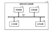
図1に表されるように、装着体設計支援装置10は、バスBU1を介して互いに接続された、処理装置11、記憶装置12、入力装置13、及び、出力装置14を備える。例えば、装着体設計支援装置10は、コンピュータ(換言すると、情報処理装置)により構成される。なお、コンピュータは、サーバ型コンピュータ、デスクトップ型コンピュータ、ラップトップ型コンピュータ、又は、タブレット型コンピュータであってよい。また、コンピュータは、据置型ゲーム機、携帯型ゲーム機、テレビ受像機、又は、スマートフォン等の少なくとも一部であってよい。また、装着体設計支援装置10は、互いに通信可能に接続された複数の装置により構成されてもよい。(Constitution)
As shown in FIG. 1, the mounting body
処理装置11は、記憶装置12に記憶されているプログラムを実行することにより、記憶装置12、入力装置13、及び、出力装置14を制御する。これにより、処理装置11は、後述する機能を実現する。 The
本例では、処理装置11は、CPU(Central Processing Unit)である。なお、処理装置11は、CPUに代えて、又は、CPUに加えて、MPU(Micro Processing Unit)、GPU(Graphics Processing Unit)、又は、DSP(Digital Signal Processor)を含んでもよい。 In this example, the
本例では、記憶装置12は、揮発性メモリと不揮発性メモリとを含む。例えば、記憶装置12は、RAM(Random Access Memory)、ROM(Read Only Memory)、半導体メモリ、有機メモリ、HDD(Hard Disk Drive)、及び、SSD(Solid State Drive)の少なくとも1つを含む。 In this example,
入力装置13は、装着体設計支援装置10の外部から情報を入力する。本例では、入力装置13は、キーボード、及び、マウスを備える。なお、入力装置13は、マイクロフォンを備えていてもよい。 The
出力装置14は、装着体設計支援装置10の外部に情報を出力する。本例では、出力装置14は、ディスプレイを備える。なお、出力装置14は、スピーカを備えていてもよい。また、装着体設計支援装置10は、入力装置13及び出力装置14の両方を構成するタッチパネル式のディスプレイを備えてもよい。 The
(機能)
装着体設計支援装置10は、生体を構成する部分の表面である生体構成面に装着される装着体の設計を支援する。本例では、生体を構成する部分は、骨折している部位を含む骨である。本例では、装着体は、骨接合用プレートである。なお、生体を構成する部分は、骨折している部位を含まない骨、又は、皮膚であってもよい。また、例えば、装着体は、装具、又は、運動を補助するための運動補助具であってもよい。(function)
The wearable body
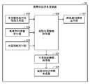
図2に表されるように、装着体設計支援装置10の機能は、生体構成面形状情報生成部101と、基準方向情報受付部102と、位置情報受付部103と、投影位置情報取得部104と、平滑曲面情報取得部105と、装着体形状情報生成部106と、異常通知情報出力部107と、を含む。 As shown in FIG. 2 , the functions of the wearable body
生体構成面形状情報生成部101は、生体構成面の三次元形状を表す生体構成面形状情報を生成する。本例では、生体構成面は、骨等値面と表されてもよい。
本例では、生体構成面形状情報生成部101は、生体を構成する部分の三次元形状を表す生体構成部形状情報に基づいて生体構成面形状情報を生成する。例えば、生体構成部形状情報は、CT(Computed Tomography)、MRI(Magnetic Resonance Imaging)、CR(Computed Radiography)、又は、DR(Digital Radiography)と呼ばれる技術を用いて取得されてよい。例えば、生体構成部形状情報は、DICOM(Digital Imaging and Communications in Medicine)と呼ばれる規格に従った情報であってよい。The living body constituting surface shape
In this example, the living body constituting surface shape
本例では、生体構成部形状情報は、予め記憶装置12に記憶されている。なお、生体構成部形状情報は、記録媒体、又は、通信回線を介して装着体設計支援装置10に入力されてよい。 In this example, the body component shape information is stored in advance in the
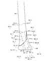
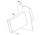
基準方向情報受付部102、及び、位置情報受付部103は、図3及び図4に表されるように、生体構成面形状情報生成部101により生成された生体構成面形状情報が表す、生体構成面BSの三次元形状を出力装置14を介して表示する。図3及び図4は、互いに異なる方向から見た生体構成面BSを表す。生体構成面BSは、骨折している部位BRを含む。 As shown in FIGS. 3 and 4, the reference direction
基準方向情報受付部102は、生体構成面BSに対して基準となる方向である基準方向RDを表す基準方向情報を受け付ける。
位置情報受付部103は、基準方向RDに直交する平面である基準平面PLにおける、装着体に対応する領域である装着体対応領域ARの位置を表す位置情報を受け付ける。The reference direction
The position
装着体対応領域ARは、長方形状である。本例では、装着体対応領域ARは、装着体の形状を含む最小の長方形状である。なお、装着体の形状は、装着体設計支援装置10のユーザによって入力装置13を介して入力された情報に基づいて設定されてよい。また、装着体の形状は、予め設定されていてもよい。
本例では、位置情報、及び、基準方向情報は、装着体設計支援装置10のユーザによって入力装置13を介して入力される。The mounting object corresponding area AR is rectangular. In this example, the mounting body corresponding area AR has a minimum rectangular shape that includes the shape of the mounting body. The shape of the wearing body may be set based on information input by the user of the wearing body
In this example, the position information and the reference direction information are input via the
投影位置情報取得部104は、生体構成面形状情報生成部101により生成された生体構成面形状情報と、基準方向情報受付部102により受け付けられた基準方向情報と、位置情報受付部103により受け付けられた位置情報と、に基づいて投影位置情報を取得する。 The projection position
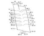
図5及び図6に表されるように、投影位置情報は、基準平面PLにおける装着体対応領域AR内のN個の標本位置SP-1~SP-Nが基準方向RDにて生体構成面BSにそれぞれ投影されたN個の投影位置PP-1~PP-Nを表す。Nは、4以上の整数を表す。本例では、Nは、15を表す。 As shown in FIGS. 5 and 6, the projection position information is such that the N sample positions SP-1 to SP-N in the mounting object corresponding area AR on the reference plane PL are projected on the living body configuration plane BS in the reference direction RD. represents N projection positions PP-1 to PP-N respectively projected onto . N represents an integer of 4 or more. In this example, N represents fifteen.
本例では、N個の標本位置SP-1~SP-Nは、格子状に位置する。本例では、N個の標本位置SP-1~SP-Nは、装着体対応領域ARの短辺方向において、所定の短辺方向間隔にて等間隔に位置するとともに、装着体対応領域ARの長辺方向において、所定の長辺方向間隔にて等間隔に位置する。本例では、短辺方向間隔と長辺方向間隔とは互いに異なる。なお、短辺方向間隔と長辺方向間隔とは互いに等しくてもよい。 In this example, N sample positions SP-1 to SP-N are located in a grid. In this example, the N sample positions SP-1 to SP-N are positioned at equal intervals in the short side direction of the mounting body corresponding area AR at predetermined intervals in the short side direction. They are positioned at equal intervals in the long side direction at predetermined intervals in the long side direction. In this example, the interval in the short side direction and the interval in the long side direction are different from each other. Note that the interval in the short side direction and the interval in the long side direction may be equal to each other.
例えば、短辺方向間隔は、装着体対応領域ARの短辺の長さが長くなるほど長くなるように設定されてよい。例えば、長辺方向間隔は、装着体対応領域ARの長辺の長さが長くなるほど長くなるように設定されてよい。また、例えば、長辺方向間隔は、装着体対応領域ARの短辺の長さが長くなるほど長くなるように設定されてよい。
また、短辺方向間隔、及び、長辺方向間隔は、装着体設計支援装置10のユーザによって入力装置13を介して入力された情報に基づいて設定されてもよい。For example, the interval in the short side direction may be set to increase as the length of the short side of the mounting object corresponding area AR increases. For example, the interval in the long side direction may be set to increase as the length of the long side of the mounting body corresponding area AR increases. Further, for example, the interval in the long side direction may be set so as to increase as the length of the short side of the mounting body corresponding area AR increases.
Also, the short side direction interval and the long side direction interval may be set based on information input by the user of the mounting body
本例では、投影位置情報取得部104は、第1投影位置補正処理、第2投影位置補正処理、及び、第3投影位置補正処理を実行する。なお、投影位置情報取得部104は、第1投影位置補正処理、第2投影位置補正処理、及び、第3投影位置補正処理の少なくとも一部を実行しなくてもよい。 In this example, the projection position
先ず、第1投影位置補正処理について説明を加える。
本例では、第1投影位置補正処理において、投影位置情報取得部104は、N個の標本位置SP-1~SP-Nのそれぞれに対して、当該標本位置SP-nである着目標本位置SP-nに対する投影位置PP-nの基準方向RDにおける成分である基準方向成分と、基準値と、の差の大きさが閾値よりも大きい場合、当該着目標本位置SP-nに対する投影位置PP-nを、当該着目標本位置SP-nに隣接する標本位置に対する投影位置である隣接投影位置に基づいて補正する。nは、1乃至Nの整数を表す。First, the first projection position correction processing will be described.
In this example, in the first projection position correction process, the projection position
本例では、投影位置PP-nは、互いに直交する、x軸、y軸、及び、z軸を有するとともに、原点が装着体対応領域ARの重心に一致し、且つ、z軸の正方向が基準方向RDに一致する直交座標系を用いて表される。従って、本例では、基準方向成分は、投影位置PP-nのz軸における座標に対応する。換言すると、基準方向成分の大きさは、投影位置PP-nの基準平面PLからの距離に対応する。なお、直交座標系の原点は、装着体対応領域ARの重心と異なる位置を有していてもよい。 In this example, the projection position PP-n has x-axis, y-axis, and z-axis that are orthogonal to each other, the origin coincides with the center of gravity of the mounting object corresponding area AR, and the positive direction of the z-axis is It is represented using a Cartesian coordinate system that coincides with the reference direction RD. Therefore, in this example, the reference direction component corresponds to the coordinates of the projection position PP-n on the z-axis. In other words, the magnitude of the reference direction component corresponds to the distance of the projection position PP-n from the reference plane PL. Note that the origin of the orthogonal coordinate system may have a position different from the center of gravity of the mounting object corresponding area AR.
具体的には、投影位置情報取得部104は、N個の標本位置SP-1~SP-Nのそれぞれに対して、当該標本位置SP-nである着目標本位置SP-nに対する投影位置PP-nの基準方向成分を取得する。 Specifically, for each of the N sample positions SP-1 to SP-N, the projection position
次いで、投影位置情報取得部104は、N個の標本位置SP-1~SP-Nに対してそれぞれ取得されたN個の投影位置PP-1~PP-Nの基準方向成分に基づいて、基準値、第1閾値、及び、第2閾値を決定する。 Next, the projection position
本例では、基準値は、N個の投影位置PP-1~PP-Nの基準方向成分の平均値である。第1閾値は、N個の投影位置PP-1~PP-Nの基準方向成分の標準偏差に、所定の第1係数を乗じた値である。本例では、第1係数は、正の実数(例えば、3.0)である。第2閾値は、N個の投影位置PP-1~PP-Nの基準方向成分の標準偏差に、所定の第2係数を乗じた値である。本例では、第2係数は、第1係数よりも小さい正の実数(例えば、1.5)である。なお、第2係数は、第1係数と等しくてもよい。 In this example, the reference value is the average value of the reference direction components of the N projection positions PP-1 to PP-N. The first threshold is a value obtained by multiplying the standard deviation of the reference direction components of the N projection positions PP-1 to PP-N by a predetermined first coefficient. In this example, the first coefficient is a positive real number (eg, 3.0). The second threshold is a value obtained by multiplying the standard deviation of the reference direction components of the N projection positions PP-1 to PP-N by a predetermined second coefficient. In this example, the second coefficient is a positive real number (eg, 1.5) that is less than the first coefficient. Note that the second coefficient may be equal to the first coefficient.
次いで、投影位置情報取得部104は、N個の標本位置SP-1~SP-Nのそれぞれに対して、当該標本位置SP-nである着目標本位置SP-nに対する投影位置PP-nの基準方向成分から、決定された基準値を減じた値である基準方向成分差を取得する。 Next, for each of the N sample positions SP-1 to SP-N, the projection position
次いで、投影位置情報取得部104は、N個の標本位置SP-1~SP-Nのそれぞれに対して、当該標本位置SP-nである着目標本位置SP-nに対して取得された基準方向成分差に基づいて、当該着目標本位置SP-nに対する投影位置PP-nを補正する必要があるか否かを判定する。 Next, for each of the N sample positions SP-1 to SP-N, the projection position
本例では、投影位置情報取得部104は、着目標本位置SP-nに対して取得された基準方向成分差が負の値を有する場合において、当該基準方向成分差の大きさが、決定された第1閾値よりも大きいとき、当該着目標本位置SP-nに対する投影位置PP-nを補正する必要があると判定し、一方、当該基準方向成分差の大きさが、決定された第1閾値以下であるとき、当該着目標本位置SP-nに対する投影位置PP-nを補正する必要がないと判定する。 In this example, when the reference direction component difference obtained for the target sample position SP-n has a negative value, the projection position
本例では、着目標本位置SP-nに対して取得された基準方向成分差が負の値を有することは、着目標本位置SP-nに対する投影位置PP-nが、平行平面よりも基準平面PLに近いことに対応する。本例では、平行平面は、基準平面PLに平行であるとともに、z軸における座標が基準値を有する位置を通る平面である。 In this example, the fact that the reference direction component difference acquired for the sample position SP-n of interest has a negative value means that the projected position PP-n with respect to the sample position SP-n of interest is closer to the reference plane than the parallel plane. It corresponds to being close to the plane PL. In this example, the parallel plane is a plane that is parallel to the reference plane PL and passes through the position whose coordinate on the z-axis has the reference value.
また、本例では、投影位置情報取得部104は、着目標本位置SP-nに対して取得された基準方向成分差が正の値を有する場合において、当該基準方向成分差の大きさが、決定された第2閾値よりも大きいとき、当該着目標本位置SP-nに対する投影位置PP-nを補正する必要があると判定し、一方、当該基準方向成分差の大きさが、決定された第2閾値以下であるとき、当該着目標本位置SP-nに対する投影位置PP-nを補正する必要がないと判定する。 Further, in this example, when the reference direction component difference obtained for the target sample position SP-n has a positive value, the projection position
本例では、着目標本位置SP-nに対して取得された基準方向成分差が正の値を有することは、着目標本位置SP-nに対する投影位置PP-nが、平行平面よりも、基準平面PLから遠いことに対応する。 In this example, the fact that the reference direction component difference acquired for the sample position SP-n of interest has a positive value means that the projected position PP-n with respect to the sample position SP-n of interest is closer to the parallel plane than the parallel plane. It corresponds to being far from the reference plane PL.
本例では、投影位置情報取得部104は、補正する必要があると判定された投影位置(換言すると、補正要投影位置)PP-nに対する標本位置(換言すると、補正要標本位置)SP-nのそれぞれに対して、当該標本位置SP-nである着目標本位置SP-nに対する拡張隣接投影位置群のうちの、補正する必要がないと判定された投影位置(換言すると、補正不要投影位置)の基準方向成分の平均値を、当該着目標本位置SP-nに対する投影位置PP-nの基準方向成分として設定することにより、当該着目標本位置SP-nに対する投影位置PP-nを補正する。 In this example, the projection position
本例では、着目標本位置SP-nに対する拡張隣接投影位置群は、着目標本位置SP-nに隣接する標本位置である直接隣接標本位置に対する投影位置である直接隣接投影位置からなる直接隣接投影位置群と、着目標本位置SP-nに隣接する2個の標本位置のそれぞれに隣接する標本位置である間接隣接標本位置に対する投影位置である間接隣接投影位置からなる間接隣接投影位置群と、からなる。 In this example, the group of extended adjacent projection positions for the sample position SP-n of interest is a group of directly adjacent projection positions that are projection positions for the immediately adjacent sample positions that are sample positions adjacent to the sample position SP-n of interest. a projection position group and an indirect adjacent projection position group consisting of indirect adjacent projection positions which are projection positions for indirect adjacent sample positions which are sample positions adjacent to each of two sample positions adjacent to the target sample position SP-n; , consisting of
本例では、着目標本位置SP-nが装着体対応領域ARの外縁を構成する4つの辺以外の位置を有する場合、直接隣接投影位置群は、4個の直接隣接投影位置からなるとともに、間接隣接投影位置群は、4個の間接隣接投影位置からなる。例えば、着目標本位置SP-5に対する直接隣接投影位置群は、投影位置PP-2、投影位置PP-4、投影位置PP-6、及び、投影位置PP-8からなる。着目標本位置SP-5に対する間接隣接投影位置群は、投影位置PP-1、投影位置PP-3、投影位置PP-7、及び、投影位置PP-9からなる。 In this example, when the specimen position SP-n of interest has a position other than the four sides forming the outer edge of the mounting object corresponding area AR, the directly adjacent projected position group consists of four directly adjacent projected positions, The group of indirectly adjacent projection positions consists of four indirectly adjacent projection positions. For example, the group of direct neighboring projection positions for the specimen position of interest SP-5 consists of projection position PP-2, projection position PP-4, projection position PP-6, and projection position PP-8. The indirectly adjacent projection position group for the target specimen position SP-5 consists of projection position PP-1, projection position PP-3, projection position PP-7, and projection position PP-9.
本例では、着目標本位置SP-nが装着体対応領域ARの外縁を構成する辺のうちの、装着体対応領域ARの外縁を構成する隅以外の位置を有する場合、直接隣接投影位置群は、3個の直接隣接投影位置からなるとともに、間接隣接投影位置群は、2個の間接隣接投影位置からなる。例えば、着目標本位置SP-7に対する直接隣接投影位置群は、投影位置PP-4、投影位置PP-8、及び、投影位置PP-10からなる。着目標本位置SP-7に対する間接隣接投影位置群は、投影位置PP-5、及び、投影位置PP-11からなる。 In this example, when the target specimen position SP-n has a position other than the corners forming the outer edge of the mounting object corresponding area AR among the sides forming the outer edge of the mounting object corresponding area AR, the directly adjacent projection position group consists of three directly adjacent projection positions, and a group of indirect neighboring projection positions consists of two indirect neighboring projection positions. For example, the group of direct neighboring projection positions for the specimen position of interest SP-7 consists of projection position PP-4, projection position PP-8, and projection position PP-10. The group of indirectly adjacent projection positions for the sample position of interest SP-7 consists of a projection position PP-5 and a projection position PP-11.
本例では、着目標本位置SP-nが装着体対応領域ARの外縁を構成する隅の位置を有する場合、直接隣接投影位置群は、2個の直接隣接投影位置からなるとともに、間接隣接投影位置群は、1個の間接隣接投影位置からなる。例えば、着目標本位置SP-3に対する直接隣接投影位置群は、投影位置PP-2、及び、投影位置PP-6からなる。着目標本位置SP-3に対する間接隣接投影位置群は、投影位置PP-5からなる。
このようにして、投影位置情報取得部104は、第1投影位置補正処理を実行する。In this example, when the target specimen position SP-n has a corner position forming the outer edge of the mounting body corresponding area AR, the group of directly adjacent projection positions consists of two directly adjacent projection positions and an indirect adjacent projection position. A position group consists of one indirect neighbor projection position. For example, the group of direct neighboring projection positions for the target specimen position SP-3 consists of projection positions PP-2 and projection positions PP-6. The group of indirect adjacent projection positions for the sample position of interest SP-3 consists of the projection position PP-5.
In this manner, the projection position
次に、第2投影位置補正処理について説明を加える。
本例では、第2投影位置補正処理において、投影位置情報取得部104は、N個の標本位置SP-1~SP-Nに対するN個の投影位置PP-1~PP-Nの基準方向成分を二値化することにより、N個の標本位置SP-1~SP-Nのそれぞれに、第1値又は第2値からなる2つの値のいずれかを割り当てる。更に、第2投影位置補正処理において、投影位置情報取得部104は、N個の標本位置SP-1~SP-Nのそれぞれに対して、当該標本位置SP-nである着目標本位置SP-nに割り当てられた値と異なる値が、当該着目標本位置SP-nに隣接するすべての標本位置に割り当てられた場合、当該着目標本位置SP-nに対する投影位置PP-nを、当該着目標本位置SP-nに隣接する標本位置に対する投影位置である隣接投影位置に基づいて補正する。Next, a description of the second projection position correction process will be added.
In this example, in the second projection position correction process, the projection position
具体的には、投影位置情報取得部104は、N個の標本位置SP-1~SP-Nのそれぞれに対して、当該標本位置SP-nである着目標本位置SP-nに対する投影位置PP-nの基準方向成分を取得する。 Specifically, for each of the N sample positions SP-1 to SP-N, the projection position
次いで、投影位置情報取得部104は、N個の標本位置SP-1~SP-Nに対してそれぞれ取得されたN個の投影位置PP-1~PP-Nの基準方向成分に基づいて、N個の投影位置PP-nの基準方向成分を二値化するための二値化閾値を決定する。本例では、二値化閾値の決定は、大津の二値化法(換言すると、大津の方法)と呼ばれる方法を用いて行われる。 Next, the projection position
次いで、投影位置情報取得部104は、N個の標本位置SP-1~SP-Nのそれぞれに対して、当該標本位置SP-nである着目標本位置SP-nに対する投影位置PP-nの基準方向成分が、二値化閾値よりも小さい場合、当該着目標本位置SP-nに第1値を割り当て、一方、二値化閾値以上である場合、当該着目標本位置SP-nに第2値を割り当てる。本例では、第2値は、第1値よりも大きい。例えば、第1値は、0であるとともに、第2値は、1であってよい。 Next, for each of the N sample positions SP-1 to SP-N, the projection position
次いで、投影位置情報取得部104は、N個の標本位置SP-1~SP-Nのそれぞれに対して、当該標本位置SP-nである着目標本位置SP-nに割り当てられた値が孤立している場合、当該着目標本位置SP-nに対する拡張隣接投影位置群を構成する、すべての拡張隣接投影位置の基準方向成分の平均値を、当該着目標本位置SP-nに対する投影位置PP-nの基準方向成分として設定することにより、当該着目標本位置SP-nに対する投影位置PP-nを補正する。 Next, for each of the N sample positions SP-1 to SP-N, the projection position
本例では、着目標本位置SP-nに割り当てられた値が孤立することは、当該着目標本位置SP-nに割り当てられた値と異なる値が、当該着目標本位置SP-nに対する直接隣接標本位置のすべてに割り当てられていることに対応する。なお、着目標本位置SP-nに割り当てられた値が孤立することは、当該着目標本位置SP-nに割り当てられた値と異なる値が、当該着目標本位置SP-nに対する、直接隣接標本位置、及び、間接隣接標本位置のすべてに割り当てられていることに対応していてもよい。
このようにして、投影位置情報取得部104は、第2投影位置補正処理を実行する。In this example, the isolation of the value assigned to the sample position of interest SP-n means that a value different from the value assigned to the sample position of interest SP-n is directly assigned to the sample position of interest SP-n. Corresponds to being assigned to all of the adjacent sample locations. The isolation of the value assigned to the target sample position SP-n means that a value different from the value assigned to the target sample position SP-n is directly adjacent to the target sample position SP-n. It may correspond to being assigned to all sample locations and indirect adjacent sample locations.
In this manner, the projection position
次に、第3投影位置補正処理について説明を加える。
本例では、第3投影位置補正処理において、投影位置情報取得部104は、N個の標本位置SP-1~SP-Nのそれぞれに対して、当該標本位置SP-nである着目標本位置SP-nを通るとともに基準方向RDにて延在する直線上に生体構成面BSが存在しない場合、当該着目標本位置SP-nに対する投影位置PP-nを、当該着目標本位置SP-nに隣接する標本位置に対する投影位置に基づいて決定する。Next, a description of the third projection position correction process will be added.
In this example, in the third projection position correction process, the projection position
具体的には、投影位置情報取得部104は、N個の標本位置SP-1~SP-Nのそれぞれに対して、当該標本位置SP-nである着目標本位置SP-nを通るとともに基準方向RDにて延在する直線(換言すると、投影直線)上に生体構成面BSが存在するか否かを判定する。 Specifically, for each of the N sample positions SP-1 to SP-N, the projection position
次いで、投影位置情報取得部104は、投影直線上に生体構成面BSが存在しないと判定された標本位置(換言すると、不存在標本位置)SP-nのそれぞれに対して、当該標本位置SP-nである着目標本位置SP-nに対する拡張隣接投影位置群のうちの、投影直線上に生体構成面BSが存在すると判定された投影位置(換言すると、存在投影位置)の基準方向成分の平均値を、当該着目標本位置SP-nに対する投影位置PP-nの基準方向成分として設定することにより、当該着目標本位置SP-nに対する投影位置PP-nを決定する。
このようにして、投影位置情報取得部104は、第3投影位置補正処理を実行する。Next, the projection position
Thus, the projection position
投影位置情報取得部104は、第1投影位置補正処理、第2投影位置補正処理、及び、第3投影位置補正処理を実行することにより補正された、N個の投影位置PP-1~PP-Nを表す投影位置情報を取得する。 The projection position
平滑曲面情報取得部105は、投影位置情報取得部104により取得された投影位置情報に基づいて、補助位置情報を取得する。補助位置情報は、M個の補助位置を表す。Mは、2以上の整数を表す。本例では、Mは、装着体対応領域ARの外縁を構成する4つの辺上に位置する標本位置SP-nの数(本例では、16)に、装着体対応領域ARの外縁を構成する隅に位置する標本位置SP-nの数(本例では、4)を加えた数(本例では、20)を表す。 The smooth curved surface
本例では、図7及び図8に表されるように、M個の補助位置は、6個の短辺拡張補助位置SU-1,SU-2,SU-3,SD-13,SD-14,SD-15からなる短辺拡張補助位置群と、10個の長辺拡張補助位置SR-3,SR-6,SR-9,SR-12,SR-15,SL-1,SL-4,SL-7,SL-10,SL-13からなる長辺拡張補助位置群と、4個の隅拡張補助位置SC-1,SC-3,SC-13,SC-15からなる隅拡張補助位置群と、からなる。 In this example, as shown in FIGS. 7 and 8, the M auxiliary positions are six short side extension auxiliary positions SU-1, SU-2, SU-3, SD-13, SD-14. , SD-15, and 10 long side extension assist positions SR-3, SR-6, SR-9, SR-12, SR-15, SL-1, SL-4, Long side extension assisting position group consisting of SL-7, SL-10, SL-13 and corner extension assisting position group consisting of four corner expanding assisting positions SC-1, SC-3, SC-13, SC-15 and consists of
本例では、短辺拡張補助位置は、装着体対応領域ARの外縁を構成する2つの短辺上に位置する標本位置SP-nに対する投影位置PP-nを短辺拡張方向へ短辺拡張距離だけ移動させた位置を有する。短辺拡張方向は、移動させる対象となる投影位置PP-nに対する標本位置SP-nが位置する短辺、及び、基準方向RDのそれぞれに直交し、且つ、装着体対応領域ARの外方へ向かう方向である。 In this example, the short side extension auxiliary position is the projection position PP-n with respect to the specimen position SP-n located on the two short sides forming the outer edge of the mounting object corresponding area AR, and the short side extension distance in the short side extension direction. has a position shifted by The direction of extension of the short side is orthogonal to the short side where the sample position SP-n is located with respect to the projection position PP-n to be moved, and the reference direction RD, and extends outward from the mounting object corresponding area AR. It is the direction to go.
本例では、短辺拡張距離は、短辺拡張方向における標本位置SP-n間の間隔(換言すると、長辺方向間隔)よりも長い。本例では、短辺拡張距離は、装着体対応領域ARの短辺の長さが長くなるほど長くなるとともに、装着体対応領域ARの長辺の長さが長くなるほど長くなるように設定される。 In this example, the short side extension distance is longer than the interval between the sample positions SP-n in the short side extension direction (in other words, the long side direction interval). In this example, the short side extension distance is set to increase as the length of the short side of the mounting body corresponding area AR increases, and to increase as the length of the long side of the mounting body corresponding area AR increases.
例えば、3個の短辺拡張補助位置SU-1,SU-2,SU-3は、装着体対応領域ARの外縁を構成する短辺上に位置する3個の標本位置SP-1,SP-2,SP-3に対する3個の投影位置PP-1,PP-2,PP-3を短辺拡張方向へ短辺拡張距離だけそれぞれ移動させた位置を有する。従って、3個の短辺拡張補助位置SU-1,SU-2,SU-3の基準方向成分は、3個の投影位置PP-1,PP-2,PP-3の基準方向成分にそれぞれ一致する。 For example, the three short-side extension auxiliary positions SU-1, SU-2, and SU-3 correspond to the three sample positions SP-1 and SP- located on the short sides forming the outer edge of the mounting body corresponding area AR. 2 and SP-3 are moved in the short side extension direction by the short side extension distance. Therefore, the reference direction components of the three short side extension auxiliary positions SU-1, SU-2, and SU-3 match the reference direction components of the three projection positions PP-1, PP-2, and PP-3, respectively. do.
本例では、長辺拡張補助位置は、装着体対応領域ARの外縁を構成する2つの長辺上に位置する標本位置SP-nに対する投影位置PP-nを長辺拡張方向へ長辺拡張距離だけ移動させた位置を有する。長辺拡張方向は、移動させる対象となる投影位置PP-nに対する標本位置SP-nが位置する長辺、及び、基準方向RDのそれぞれに直交し、且つ、装着体対応領域ARの外方へ向かう方向である。 In this example, the long side expansion auxiliary position is the projection position PP-n with respect to the sample position SP-n located on the two long sides forming the outer edge of the mounting object corresponding area AR, and the long side expansion distance in the long side expansion direction. has a position shifted by The direction of extension of the long side is orthogonal to the long side where the sample position SP-n is located with respect to the projection position PP-n to be moved, and the reference direction RD, and extends outward from the mounting object corresponding area AR. It is the direction to go.
本例では、長辺拡張距離は、長辺拡張方向における標本位置SP-n間の間隔(換言すると、短辺方向間隔)よりも長い。本例では、長辺拡張距離は、装着体対応領域ARの短辺の長さが長くなるほど長くなるとともに、装着体対応領域ARの長辺の長さが長くなるほど長くなるように設定される。本例では、長辺拡張距離は、短辺拡張距離よりも長い。 In this example, the long side extension distance is longer than the interval between the sample positions SP-n in the long side extension direction (in other words, the interval in the short side direction). In this example, the long side expansion distance is set to be longer as the short side of the mounting body corresponding area AR is longer and longer as the long side of the mounting body corresponding area AR is longer. In this example, the long side extension distance is longer than the short side extension distance.
例えば、5個の長辺拡張補助位置SR-3,SR-6,SR-9,SR-12,SR-15は、装着体対応領域ARの外縁を構成する長辺上に位置する5個の標本位置SP-3,SP-6,SP-9,SP-12,SP-15に対する5個の投影位置PP-3,PP-6,PP-9,PP-12,PP-15を長辺拡張方向へ長辺拡張距離だけそれぞれ移動させた位置を有する。従って、5個の長辺拡張補助位置SR-3,SR-6,SR-9,SR-12,SR-15の基準方向成分は、5個の投影位置PP-3,PP-6,PP-9,PP-12,PP-15の基準方向成分にそれぞれ一致する。 For example, the five long side extension auxiliary positions SR-3, SR-6, SR-9, SR-12, and SR-15 are five positions located on the long sides forming the outer edge of the mounted body corresponding area AR. Long side extension of five projection positions PP-3, PP-6, PP-9, PP-12, PP-15 for sample positions SP-3, SP-6, SP-9, SP-12, SP-15 It has a position moved by the long side expansion distance in each direction. Therefore, the reference direction components of the five long side extension auxiliary positions SR-3, SR-6, SR-9, SR-12 and SR-15 are the five projection positions PP-3, PP-6 and PP- 9, PP-12, and PP-15, respectively.
本例では、隅拡張補助位置は、装着体対応領域ARの外縁を構成する4つの隅上に位置する標本位置SP-nに対する投影位置PP-nを、短辺拡張方向へ短辺拡張距離だけ移動させるとともに長辺拡張方向へ長辺拡張距離だけ移動させた位置を有する。 In this example, the corner extension auxiliary positions are the projection positions PP-n with respect to the specimen positions SP-n located on the four corners forming the outer edge of the mounting object corresponding area AR, and are extended by the short side extension distance in the short side extension direction. It is moved and has a position that is moved by the long side extension distance in the long side extension direction.
例えば、隅拡張補助位置SC-13は、装着体対応領域ARの外縁を構成する隅に位置する標本位置SP-13に対する投影位置PP-13を、短辺拡張方向へ短辺拡張距離だけ移動させるとともに長辺拡張方向へ長辺拡張距離だけ移動させた位置を有する。従って、隅拡張補助位置SC-13の基準方向成分は、投影位置PP-13の基準方向成分に一致する。 For example, the corner extension auxiliary position SC-13 moves the projected position PP-13 with respect to the sample position SP-13 located at the corner forming the outer edge of the mounting object corresponding area AR by the short side extension distance in the short side extension direction. and a position moved in the long side extension direction by the long side extension distance. Therefore, the reference direction component of the corner expansion assistance position SC-13 matches the reference direction component of the projection position PP-13.
図9に表されるように、平滑曲面情報取得部105は、投影位置情報取得部104により取得された投影位置情報が表すN個の投影位置PP-1~PP-Nと、取得された補正位置情報が表すM個の補助位置SU-1,SU-2,SU-3,SD-13,SD-14,SD-15,SR-3,SR-6,SR-9,SR-12,SR-15,SL-1,SL-4,SL-7,SL-10,SL-13,SC-1,SC-3,SC-13,SC-15と、を制御点群として用いることにより定められる平滑な曲面である平滑曲面SSを表す平滑曲面情報を取得する。 As shown in FIG. 9, the smooth curved surface
本例では、平滑曲面SSは、Bスプライン(B-Spline)曲面である。なお、平滑曲面は、Bスプライン曲面以外のスプライン曲面(例えば、NURBS(Non-Uniform Rational B-Spline)曲面)、又は、ベジェ曲面であってもよい。 In this example, the smooth curved surface SS is a B-Spline curved surface. The smooth curved surface may be a spline curved surface other than the B-spline curved surface (for example, a NURBS (Non-Uniform Rational B-Spline) curved surface) or a Bezier curved surface.
なお、平滑曲面情報取得部105は、補助位置を制御点群として用いることなく、N個の投影位置PP-1~PP-Nのみを制御点群として用いることにより定められる平滑な曲面である平滑曲面SSを表す平滑曲面情報を取得してもよい。 Note that the smooth curved surface
装着体形状情報生成部106は、平滑曲面情報取得部105により取得された平滑曲面情報に基づいて、当該平滑曲面情報が表す平滑曲面SSの少なくとも一部(例えば、一部、又は、全部)を装着体が有するように装着体の三次元形状を表す装着体形状情報を生成する。 Based on the smooth curved surface information acquired by the smooth curved surface
具体的には、図10に表されるように、装着体形状情報生成部106は、平滑曲面SSを基準方向RDに沿って(本例では、基準方向RDと逆方向へ)第1距離だけ移動させることにより形成される第1移動立体MC1の三次元形状を表す第1移動立体情報を生成する。 Specifically, as shown in FIG. 10, the mounted body shape
次いで、図11に表されるように、装着体形状情報生成部106は、装着体対応領域ARを基準方向RDに沿って(本例では、基準方向RDへ)、第1距離よりも長い第2距離だけ移動させることにより形成される第2移動立体MC2の三次元形状を表す第2移動立体情報を生成する。 Next, as shown in FIG. 11, the mounted body shape
次いで、図12及び図13に表されるように、装着体形状情報生成部106は、生成された、第1移動立体情報及び第2移動立体情報に基づいて、第1移動立体MC1と、第2移動立体MC2と、が交差することにより生成される交差立体CCの三次元形状を表す交差立体情報を生成する。 Next, as shown in FIGS. 12 and 13, the mounted body shape
次いで、装着体形状情報生成部106は、生成された交差立体情報に基づいて装着体形状情報を生成する。本例では、装着体形状情報生成部106は、交差立体情報が表す交差立体CCの角の少なくとも一部を丸めた(換言すると、交差立体CCの角の少なくとも一部がフィレット加工された)三次元形状を、装着体の三次元形状として表す装着体形状情報を生成する。なお、装着体形状情報生成部106は、交差立体情報が表す交差立体CCの三次元形状を、装着体の三次元形状として表す装着体形状情報を生成してもよい。 Next, the mounted body shape
異常通知情報出力部107は、投影位置情報取得部104により取得された投影位置情報に基づいて、処理異常条件が成立するか否かを判定する。本例では、異常通知情報出力部107は、第1投影位置補正処理、第2投影位置補正処理、及び、第3投影位置補正処理を実行する前に取得された投影位置情報に基づいて上記判定を行う。 The abnormality notification
本例では、処理異常条件は、不存在比が所定の異常閾値よりも大きい、という条件である。不存在比は、N個の標本位置SP-1~SP-Nの総数(本例では、N)に対する、N個の標本位置SP-1~SP-Nのうちの、当該標本位置SP-nを通るとともに基準方向RDにて延在する直線(換言すると、投影直線)上に生体構成面BSが存在しない標本位置SP-nの数の比である。本例では、異常閾値は、0よりも大きく、且つ、1よりも小さい実数である。 In this example, the processing abnormality condition is that the nonexistence ratio is greater than a predetermined abnormality threshold. The absence ratio is the sample position SP-n among the N sample positions SP-1 to SP-N with respect to the total number of the N sample positions SP-1 to SP-N (N in this example). , and extending in the reference direction RD (in other words, projection straight line). In this example, the anomaly threshold is a real number greater than 0 and less than 1.
異常通知情報出力部107は、処理異常条件が成立する場合、装着体形状情報を正常に生成できない旨を表す異常通知情報を出力装置14を介して出力する。
なお、装着体設計支援装置10の機能は、異常通知情報出力部107を含まなくてもよい。
装着体設計支援装置10の機能の説明は、以下の装着体設計支援装置10の動作の説明によって補足されてよい。The abnormality notification
Note that the function of the wearing body
The description of the functions of the mounted body
(動作)
次に、装着体設計支援装置10の動作について、図14乃至図17を参照しながら説明する。
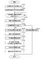
装着体設計支援装置10は、装着体設計支援装置10のユーザにより入力装置13を介して入力される実行指示に従って、図14に表される処理を実行する。
先ず、装着体設計支援装置10は、生体構成面形状情報を生成する(図14のステップS101)。(motion)
Next, the operation of the wearing body
The mounted body
First, the wearing body
次いで、装着体設計支援装置10は、ステップS101にて生成された生体構成面形状情報が表す、生体構成面BSの三次元形状を出力装置14を介して表示する(図14のステップS102)。 Next, the mounting body
次いで、装着体設計支援装置10は、基準平面PLにおける装着体対応領域ARの位置を表す位置情報と、基準方向RDを表す基準方向情報と、を受け付けるまで待機する(図14のステップS103の「No」ルート)。 Next, the mounted body
装着体設計支援装置10は、位置情報、及び、基準方向情報が入力装置13を介して装着体設計支援装置10に入力された場合、位置情報、及び、基準方向情報を受け付け、ステップS103にて「Yes」と判定し、ステップS104へ進む。 When the position information and the reference direction information are input to the mounted body
次いで、装着体設計支援装置10は、ステップS101にて生成された生体構成面形状情報と、ステップS103にて受け付けられた、位置情報、及び、基準方向情報と、に基づいて投影位置情報を取得する(図14のステップS104)。 Next, the mounted body
次いで、装着体設計支援装置10は、ステップS104にて取得された投影位置情報に基づいて、処理異常条件が成立するか否かを判定する(図14のステップS105)。
装着体設計支援装置10は、処理異常条件が成立しない場合、ステップS105にて「No」と判定し、ステップS106へ進む。Next, based on the projection position information acquired in step S104, the mounted body
When the processing abnormality condition is not satisfied, the mounted body
次いで、装着体設計支援装置10は、投影位置補正処理を実行する(図14のステップS106)。本例では、装着体設計支援装置10は、投影位置補正処理において、図15に表される第3投影位置補正処理を実行し、その後、図16に表される第1投影位置補正処理を実行し、その後、図17に表される第2投影位置補正処理を実行する。
なお、装着体設計支援装置10は、第1投影位置補正処理の前に、第2投影位置補正処理を実行してもよい。Next, the mounted body
Note that the mounted body
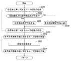
図15に表されるように、第3投影位置補正処理において、装着体設計支援装置10は、N個の標本位置SP-1~SP-Nのそれぞれを1つずつ順に処理対象として用いるループ処理(ステップS201~ステップS205)を実行する。 As shown in FIG. 15, in the third projection position correction process, the mounted body
このループ処理において、装着体設計支援装置10は、処理対象の標本位置SP-nである着目標本位置SP-nを通るとともに基準方向RDにて延在する直線(換言すると、投影直線)上に生体構成面BSが存在するか否かを判定する(図15のステップS202)。 In this loop processing, the mounting body
装着体設計支援装置10は、投影直線上に生体構成面BSが存在する場合、ステップS202にて「Yes」と判定し、生体構成面BSが存在する旨を表す存在情報を着目標本位置SP-nと対応付けて保持する(図15のステップS203)。 If the body structure plane BS exists on the projected straight line, the mounted body
また、装着体設計支援装置10は、投影直線上に生体構成面BSが存在しない場合、ステップS202にて「No」と判定し、生体構成面BSが存在しない旨を表す不存在情報を着目標本位置SP-nと対応付けて保持する(図15のステップS204)。 If the body structure plane BS does not exist on the projected straight line, the mounted body
次いで、装着体設計支援装置10は、N個の標本位置SP-1~SP-Nのすべてに対して、上記ループ処理(ステップS201~ステップS205)を実行した後、ステップS206へ進む。 Next, the mounting body
次いで、装着体設計支援装置10は、N個の標本位置SP-1~SP-Nのうちの、ステップS204にて不存在情報と対応付けられた標本位置である不存在標本位置SP-nのそれぞれを1つずつ順に処理対象として用いるループ処理(ステップS206~ステップS208)を実行する。 Next, the mounting body
このループ処理において、装着体設計支援装置10は、処理対象の不存在標本位置SP-nである着目標本位置SP-nに対する拡張隣接投影位置群のうちの、ステップS204にて存在情報と対応付けられた標本位置である存在標本位置に対する投影位置(換言すると、存在投影位置)の基準方向成分の平均値を、当該着目標本位置SP-nに対する投影位置PP-nの基準方向成分として設定することにより、当該着目標本位置SP-nに対する投影位置PP-nを決定する(図15のステップS207)。 In this loop processing, the mounting body
次いで、装着体設計支援装置10は、不存在標本位置SP-nのすべてに対して、上記ループ処理(ステップS206~ステップS208)を実行した後、図15の処理を終了する。 Next, the mounted body
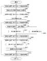
次いで、図16に表されるように、第1投影位置補正処理において、装着体設計支援装置10は、N個の標本位置SP-1~SP-Nのそれぞれを1つずつ順に処理対象として用いるループ処理(ステップS301~ステップS303)を実行する。 Next, as shown in FIG. 16, in the first projection position correction process, the mounted body
このループ処理において、装着体設計支援装置10は、処理対象の標本位置SP-nである着目標本位置SP-nに対する投影位置PP-nの基準方向成分を取得する(図16のステップS302)。 In this loop processing, the mounting body
次いで、装着体設計支援装置10は、N個の標本位置SP-1~SP-Nのすべてに対して、上記ループ処理(ステップS301~ステップS303)を実行した後、ステップS304へ進む。 Next, the mounting body
次いで、装着体設計支援装置10は、ステップS302にて、N個の標本位置SP-1~SP-Nに対してそれぞれ取得されたN個の投影位置PP-1~PP-Nの基準方向成分に基づいて、基準値、第1閾値、及び、第2閾値を決定する(図16のステップS304)。 Next, in step S302, the mounted body
次いで、装着体設計支援装置10は、N個の標本位置SP-1~SP-Nのそれぞれを1つずつ順に処理対象として用いるループ処理(ステップS305~ステップS312)を実行する。 Next, the mounting body
このループ処理において、装着体設計支援装置10は、処理対象の標本位置SP-nである着目標本位置SP-nに対する投影位置PP-nの基準方向成分から、ステップS304にて決定された基準値を減じた値である基準方向成分差を取得する(図16のステップS306)。 In this loop processing, the mounting body
次いで、装着体設計支援装置10は、ステップS306にて取得された基準方向成分差が0よりも小さいか否かを判定する(図16のステップS307)。
基準方向成分差が0よりも小さい場合、装着体設計支援装置10は、ステップS307にて「Yes」と判定し、基準方向成分差の大きさが、ステップS304にて決定された第1閾値よりも大きいか否かを判定する(図16のステップS308)。Next, the mounted body
If the reference direction component difference is smaller than 0, the mounted body
基準方向成分差の大きさが第1閾値よりも大きい場合、装着体設計支援装置10は、ステップS308にて「Yes」と判定し、当該着目標本位置SP-nに対する投影位置PP-nを補正する必要がある旨を表す補正要情報を当該着目標本位置SP-nと対応付けて保持する(図16のステップS309)。 If the magnitude of the reference direction component difference is greater than the first threshold, the mounted body
また、基準方向成分差の大きさが第1閾値以下である場合、装着体設計支援装置10は、ステップS308にて「No」と判定し、当該着目標本位置SP-nに対する投影位置PP-nを補正する必要がない旨を表す補正不要情報を当該着目標本位置SP-nと対応付けて保持する(図16のステップS310)。 Further, when the magnitude of the reference direction component difference is equal to or less than the first threshold value, the mounted body
また、基準方向成分差が0以上である場合、装着体設計支援装置10は、ステップS307にて「No」と判定し、基準方向成分差の大きさが、ステップS304にて決定された第2閾値よりも大きいか否かを判定する(図16のステップS311)。 Further, when the reference direction component difference is 0 or more, the mounted body
基準方向成分差の大きさが第2閾値よりも大きい場合、装着体設計支援装置10は、ステップS311にて「Yes」と判定し、当該着目標本位置SP-nに対する投影位置PP-nを補正する必要がある旨を表す補正要情報を当該着目標本位置SP-nと対応付けて保持する(図16のステップS309)。 If the magnitude of the reference direction component difference is greater than the second threshold, the mounted body
また、基準方向成分差の大きさが第2閾値以下である場合、装着体設計支援装置10は、ステップS311にて「No」と判定し、当該着目標本位置SP-nに対する投影位置PP-nを補正する必要がない旨を表す補正不要情報を当該着目標本位置SP-nと対応付けて保持する(図16のステップS310)。 Further, when the magnitude of the reference direction component difference is equal to or less than the second threshold, the mounted body
次いで、装着体設計支援装置10は、N個の標本位置SP-1~SP-Nのすべてに対して、上記ループ処理(ステップS305~ステップS312)を実行した後、ステップS313へ進む。 Next, the mounting body
次いで、装着体設計支援装置10は、N個の標本位置SP-1~SP-Nのうちの、ステップS309にて補正要情報と対応付けられた標本位置SP-nである補正要標本位置SP-nのそれぞれを1つずつ順に処理対象として用いるループ処理(ステップS313~ステップS315)を実行する。 Next, the mounting body
このループ処理において、装着体設計支援装置10は、処理対象の補正要標本位置SP-nである着目標本位置SP-nに対する拡張隣接投影位置群のうちの、補正不要情報が対応付けられた標本位置に対する投影位置(換言すると、補正不要投影位置)の基準方向成分の平均値を、当該着目標本位置SP-nに対する投影位置PP-nの基準方向成分として設定することにより、当該着目標本位置SP-nに対する投影位置PP-nを補正する(図16のステップS314)。 In this loop processing, the mounting body
次いで、装着体設計支援装置10は、補正要標本位置SP-nのすべてに対して、上記ループ処理(ステップS313~ステップS315)を実行した後、図16の処理を終了する。 Next, the mounted body
次いで、図17に表されるように、第2投影位置補正処理において、装着体設計支援装置10は、N個の標本位置SP-1~SP-Nのそれぞれを1つずつ順に処理対象として用いるループ処理(ステップS401~ステップS403)を実行する。 Next, as shown in FIG. 17, in the second projection position correction process, the mounted body
このループ処理において、装着体設計支援装置10は、処理対象の標本位置SP-nである着目標本位置SP-nに対する投影位置PP-nの基準方向成分を取得する(図17のステップS402)。 In this loop processing, the mounting body
次いで、装着体設計支援装置10は、N個の標本位置SP-1~SP-Nのすべてに対して、上記ループ処理(ステップS401~ステップS403)を実行した後、ステップS404へ進む。 Next, the mounting body
次いで、装着体設計支援装置10は、ステップS402にて、N個の標本位置SP-1~SP-Nに対してそれぞれ取得されたN個の投影位置PP-1~PP-Nの基準方向成分に基づいて、二値化閾値を決定する(図17のステップS404)。 Next, in step S402, the mounted body
次いで、装着体設計支援装置10は、N個の標本位置SP-1~SP-Nのそれぞれを1つずつ順に処理対象として用いるループ処理(ステップS405~ステップS409)を実行する。 Next, the mounting body
このループ処理において、装着体設計支援装置10は、処理対象の標本位置SP-nである着目標本位置SP-nに対する投影位置PP-nの基準方向成分が、ステップS404にて決定された二値化閾値よりも小さいか否かを判定する(図17のステップS406)。 In this loop processing, the mounting body
投影位置PP-nの基準方向成分が二値化閾値よりも小さい場合、装着体設計支援装置10は、ステップS406にて「Yes」と判定し、第1値を表す第1値情報を着目標本位置SP-nと対応付けて保持することにより、着目標本位置SP-nに第1値を割り当てる(図17のステップS407)。
また、投影位置PP-nの基準方向成分が二値化閾値以上である場合、装着体設計支援装置10は、ステップS406にて「No」と判定し、第2値を表す第2値情報を着目標本位置SP-nと対応付けて保持することにより、着目標本位置SP-nに第2値を割り当てる(図17のステップS408)。If the reference direction component of the projection position PP-n is smaller than the binarization threshold, the mounted body
Further, when the reference direction component of the projection position PP-n is equal to or greater than the binarization threshold, the mounted body
次いで、装着体設計支援装置10は、N個の標本位置SP-1~SP-Nのすべてに対して、上記ループ処理(ステップS405~ステップS409)を実行した後、ステップS410へ進む。 Next, the mounting body
次いで、装着体設計支援装置10は、N個の標本位置SP-1~SP-Nのそれぞれを1つずつ順に処理対象として用いるループ処理(ステップS410~ステップS413)を実行する。 Next, the mounting body
このループ処理において、装着体設計支援装置10は、処理対象の標本位置SP-nである着目標本位置SP-nに割り当てられた値が孤立しているか否かを判定する(図17のステップS411)。 In this loop processing, the mounting body
着目標本位置SP-nに割り当てられた値が孤立している場合、装着体設計支援装置10は、ステップS411にて「Yes」と判定し、当該着目標本位置SP-nに対する拡張隣接投影位置群を構成する、すべての拡張隣接投影位置の基準方向成分の平均値を、当該着目標本位置SP-nに対する投影位置PP-nの基準方向成分として設定することにより、当該着目標本位置SP-nに対する投影位置PP-nを補正する(図17のステップS412)。 When the value assigned to the target sample position SP-n is isolated, the mounted body
また、着目標本位置SP-nに割り当てられた値が孤立していない場合、装着体設計支援装置10は、ステップS411にて「No」と判定し、ステップS412の処理を実行することなく、ステップS413へ進む。 Further, when the value assigned to the target specimen position SP-n is not isolated, the mounted body
次いで、装着体設計支援装置10は、N個の標本位置SP-1~SP-Nのすべてに対して、上記ループ処理(ステップS410~ステップS413)を実行した後、図17の処理を終了する。
このようにして、装着体設計支援装置10は、図14のステップS106にて、投影位置補正処理を実行する。Next, the mounting body
In this manner, the mounting body
次いで、装着体設計支援装置10は、ステップS106にて補正されたN個の投影位置PP-1~PP-Nを表す投影位置情報に基づいて、補助位置情報を取得する(図14のステップS107)。 Next, the mounted body
次いで、装着体設計支援装置10は、ステップS106にて補正されたN個の投影位置PP-1~PP-Nを表す投影位置情報と、ステップS107にて取得された補助位置情報と、に基づいて平滑曲面情報を取得する(図14のステップS108)。 Next, based on the projection position information representing the N projection positions PP-1 to PP-N corrected in step S106 and the auxiliary position information acquired in step S107, the mounted body
次いで、装着体設計支援装置10は、ステップS108にて取得された平滑曲面情報と、ステップS103にて受け付けられた位置情報及び基準方向情報と、に基づいて、第1移動立体情報、及び、第2移動立体情報を取得する(図14のステップS109)。 Next, based on the smooth curved surface information acquired in step S108 and the position information and reference direction information received in step S103, the mounted body
次いで、装着体設計支援装置10は、ステップS109にて取得された、第1移動立体情報、及び、第2移動立体情報に基づいて交差立体情報を生成する(図14のステップS110)。
次いで、装着体設計支援装置10は、ステップS110にて生成された交差立体情報に基づいて装着体形状情報を生成する(図14のステップS111)。
次いで、装着体設計支援装置10は、図14の処理を終了する。Next, the wearing body
Next, the mounted body
Next, the mounting body
なお、装着体設計支援装置10は、ステップS105にて処理異常条件が成立する場合、ステップS105にて「Yes」と判定し、ステップS112へ進む。次いで、装着体設計支援装置10は、異常通知情報を出力装置14を介して出力する。次いで、装着体設計支援装置10は、ステップS106~ステップS111の処理を実行することなく、図14の処理を終了する。 It should be noted that when the processing abnormality condition is established in step S105, the mounted body
以上、説明したように、第1実施形態の装着体設計支援装置10は、生体を構成する部分の表面である生体構成面BSに装着される装着体の設計を支援する。
装着体設計支援装置10は、基準方向情報受付部102と、位置情報受付部103と、投影位置情報取得部104と、平滑曲面情報取得部105と、装着体形状情報生成部106と、を備える。As described above, the wearable object
The mounting body
基準方向情報受付部102は、生体構成面BSに対して基準となる方向である基準方向RDを表す基準方向情報を受け付ける。
位置情報受付部103は、基準方向RDに直交する平面である基準平面PLにおける、装着体に対応する領域である装着体対応領域ARの位置を表す位置情報を受け付ける。The reference direction
The position
投影位置情報取得部104は、生体構成面BSの三次元形状を表す生体構成面形状情報と、受け付けられた基準方向情報と、受け付けられた位置情報と、に基づいて、基準平面PLにおける装着体対応領域AR内の複数の標本位置SP-1~SP-Nが基準方向RDにて生体構成面BSにそれぞれ投影された複数の投影位置PP-1~PP-Nを表す投影位置情報を取得する。 The projection position
平滑曲面情報取得部105は、取得された投影位置情報に基づいて、複数の投影位置PP-1~PP-Nを制御点群として用いることにより定められる平滑な曲面である平滑曲面SSを表す平滑曲面情報を取得する。
装着体形状情報生成部106は、取得された平滑曲面情報に基づいて、平滑曲面SSの少なくとも一部を装着体が有するように装着体の三次元形状を表す装着体形状情報を生成する。Based on the acquired projection position information, the smooth curved surface
Based on the obtained smooth curved surface information, the mounted body shape
これによれば、装着体設計支援装置10のユーザは、基準方向情報、及び、位置情報を装着体設計支援装置10に入力することにより、装着体形状情報を容易に生成することができる。従って、基準方向RD、及び、装着体対応領域ARの位置に応じた装着体の設計を容易に行うことができる。
また、装着体設計支援装置10によれば、装着体が平滑曲面SSの少なくとも一部を有するように装着体形状情報が生成される。従って、生体構成面BSに十分に適合できる装着体の設計を支援できる。According to this, the user of the mounted body
Further, according to the mounting body
更に、第1実施形態の装着体設計支援装置10において、装着体形状情報生成部106は、平滑曲面SSを基準方向RDに沿って第1距離だけ移動させることにより形成される第1移動立体MC1と、装着体対応領域ARを基準方向RDに沿って第1距離よりも長い第2距離だけ移動させることにより形成される第2移動立体MC2と、が交差することにより生成される交差立体CCの三次元形状を表す交差立体情報を生成し、生成された交差立体情報に基づいて装着体形状情報を生成する。 Furthermore, in the mounted body
これによれば、基準方向RDにて装着体を見た場合において、装着体対応領域ARの形状を有し、且つ、生体構成面BSに適合する板状である装着体を容易に設計できる。従って、例えば、骨折している部位を接合するために当該部位を含む骨の表面に装着される骨接合用プレートを容易に設計できる。 According to this, when the mounting body is viewed in the reference direction RD, it is possible to easily design the mounting body having the shape of the mounting body corresponding area AR and having a plate shape that conforms to the biostructure plane BS. Therefore, for example, an osteosynthesis plate can be easily designed to be attached to the surface of a bone containing a fractured site in order to bond the site.
更に、第1実施形態の装着体設計支援装置10において、装着体対応領域ARは、長方形状であり、複数の標本位置SP-1~SP-Nは、格子状に位置する。 Furthermore, in the mounting body
これによれば、互いに隣接する標本位置SP-n間の距離を調整することにより、平滑曲面SSが生体構成面BSに適合する程度(換言すると、平滑曲面SSの生体構成面BSに対する適合度)を容易に調整することができる。 According to this, by adjusting the distance between the sample positions SP-n adjacent to each other, the degree of conformity of the smooth curved surface SS to the biomedical structure surface BS (in other words, the degree of conformity of the smooth curved surface SS to the biomedical structure surface BS) can be easily adjusted.
更に、第1実施形態の装着体設計支援装置10において、平滑曲面情報取得部105は、装着体対応領域ARの外縁を構成する4つの辺のそれぞれに対して、当該辺、及び、基準方向RDのそれぞれに直交し、且つ、装着体対応領域ARの外方へ向かう方向である拡張方向へ、当該辺上に位置する標本位置SP-nに対する投影位置PP-nを移動させた補助位置SU-1,SU-2,SU-3,SD-13,SD-14,SD-15,SR-3,SR-6,SR-9,SR-12,SR-15,SL-1,SL-4,SL-7,SL-10,SL-13,SC-1,SC-3,SC-13,SC-15を、複数の投影位置PP-1~PP-Nに加えて制御点群として用いる。 Furthermore, in the mounting body
これによれば、装着体対応領域ARの外縁の近傍における、平滑曲面SSの生体構成面BSに対する適合度を高めることができる。 According to this, it is possible to improve the degree of conformity of the smooth curved surface SS to the biostructure surface BS in the vicinity of the outer edge of the mounting body corresponding area AR.
更に、第1実施形態の装着体設計支援装置10において、投影位置情報取得部104は、複数の標本位置SP-1~SP-Nの1つである着目標本位置SP-nに対する投影位置PP-nの基準方向RDにおける成分と、基準値と、の差の大きさが閾値よりも大きい場合、当該着目標本位置SP-nに対する投影位置PP-nを、当該着目標本位置SP-nに隣接する標本位置に対する投影位置に基づいて補正する。 Furthermore, in the mounted body
ところで、投影位置PP-nの基準方向RDにおける成分と、基準値と、の差の大きさが過大である投影位置PP-nが存在する場合、平滑曲面SSの生体構成面BSに対する適合度が過度に低くなる虞がある。
これに対し、装着体設計支援装置10によれば、投影位置PP-nの基準方向RDにおける成分と、基準値と、の差の大きさが過大である投影位置PP-nを補正できる。従って、平滑曲面SSの生体構成面BSに対する適合度が過度に低くなることを抑制できる。By the way, when there is a projection position PP-n in which the difference between the component of the projection position PP-n in the reference direction RD and the reference value is excessive, the degree of conformity of the smooth curved surface SS to the biostructure plane BS is low. There is a risk that it will be too low.
On the other hand, according to the mounting body
更に、第1実施形態の装着体設計支援装置10において、投影位置情報取得部104は、複数の標本位置SP-1~SP-Nに対する複数の投影位置PP-1~PP-Nの基準方向RDにおける成分を二値化することにより、複数の標本位置SP-1~SP-Nのそれぞれに、第1値又は第2値からなる2つの値のいずれかを割り当てるとともに、複数の標本位置SP-1~SP-Nの1つである着目標本位置SP-nに割り当てられた値と異なる値が、当該着目標本位置SP-nに隣接するすべての標本位置に割り当てられた場合、当該着目標本位置SP-nに対する投影位置PP-nを、当該着目標本位置SP-nに隣接する標本位置に対する投影位置に基づいて補正する。 Furthermore, in the mounted body
ところで、投影位置PP-nの基準方向RDにおける成分が、当該投影位置PP-nに隣接する投影位置と過度に大きく異なる投影位置PP-nが存在する場合、平滑曲面SSの生体構成面BSに対する適合度が過度に低くなる虞がある。
これに対し、装着体設計支援装置10によれば、投影位置PP-nの基準方向RDにおける成分が、当該投影位置PP-nに隣接する投影位置と過度に大きく異なる投影位置PP-nを補正できる。従って、平滑曲面SSの生体構成面BSに対する適合度が過度に低くなることを抑制できる。By the way, when there is a projected position PP-n in which the component of the projected position PP-n in the reference direction RD is excessively different from the projected position adjacent to the projected position PP-n, the smooth curved surface SS with respect to the biological body structure plane BS There is a risk that the degree of conformity will be excessively low.
On the other hand, according to the mounting body
更に、第1実施形態の装着体設計支援装置10において、投影位置情報取得部104は、複数の標本位置SP-1~SP-Nの1つである着目標本位置SP-nを通るとともに基準方向RDにて延在する直線上に生体構成面BSが存在しない場合、当該着目標本位置SP-nに対する投影位置PP-nを、当該着目標本位置SP-nに隣接する標本位置に対する投影位置に基づいて決定する。 Furthermore, in the mounted body
ところで、標本位置SP-nを通るとともに基準方向RDにて延在する直線上に生体構成面BSが存在しない場合、当該標本位置SP-nに対する投影位置PP-nを適切に設定しないと、平滑曲面SSの生体構成面BSに対する適合度が過度に低くなる虞がある。
これに対し、装着体設計支援装置10によれば、標本位置SP-nを通るとともに基準方向RDにて延在する直線上に生体構成面BSが存在しない場合、当該標本位置SP-nに対する投影位置PP-nが、当該投影位置PP-nに隣接する投影位置に基づいて決定される。従って、平滑曲面SSの生体構成面BSに対する適合度が過度に低くなることを抑制できる。By the way, in the case where the body structure plane BS does not exist on a straight line passing through the sample position SP-n and extending in the reference direction RD, the projection position PP-n with respect to the sample position SP-n is not appropriately set, otherwise the smooth There is a possibility that the degree of conformity of the curved surface SS to the biostructure surface BS will be excessively low.
On the other hand, according to the mounting object
更に、第1実施形態の装着体設計支援装置10は、複数の標本位置SP-1~SP-Nの総数に対する、複数の標本位置SP-1~SP-Nのうちの、当該標本位置SP-nを通るとともに基準方向RDにて延在する直線上に生体構成面BSが存在しない標本位置SP-nの数の比が異常閾値よりも大きい場合、装着体形状情報を正常に生成できない旨を表す異常通知情報を出力する異常通知情報出力部107を備える。 Further, the mounting object
ところで、標本位置SP-nを通るとともに基準方向RDにて延在する直線上に生体構成面BSが存在しない標本位置SP-nの数の、標本位置SP-1~SP-Nの総数に対する比が高くなるほど、生体構成面BSに十分に適合する平滑曲面SSが生成される確率が低くなる。従って、装着体設計支援装置10によれば、装着体が生体構成面BSに十分に適合しない虞を、装着体設計支援装置10のユーザに認識させることができる。 By the way, the ratio of the number of sample positions SP-n where the biological structure plane BS does not exist on a straight line passing through the sample position SP-n and extending in the reference direction RD to the total number of sample positions SP-1 to SP-N , the probability of generating a smooth curved surface SS that satisfactorily matches the biostructure surface BS decreases. Therefore, according to the mounting body
なお、本発明は、上述した実施形態に限定されない。例えば、上述した実施形態に、本発明の趣旨を逸脱しない範囲内において当業者が理解し得る様々な変更が加えられてよい。 In addition, this invention is not limited to embodiment mentioned above. For example, various modifications that can be understood by those skilled in the art may be added to the above-described embodiments without departing from the scope of the present invention.
10 装着体設計支援装置
11 処理装置
12 記憶装置
13 入力装置
14 出力装置
101 生体構成面形状情報生成部
102 基準方向情報受付部
103 位置情報受付部
104 投影位置情報取得部
105 平滑曲面情報取得部
106 装着体形状情報生成部
107 異常通知情報出力部
AR 装着体対応領域
BS 生体構成面
BU1 バス
CC 交差立体
MC1 第1移動立体
MC2 第2移動立体
PL 基準平面
PP-1~PP-N 投影位置
RD 基準方向
SC-1,SC-3,SC-13,SC-15 隅拡張補助位置
SP-1~SP-N 標本位置
SR-3,SR-6,SR-9,SR-12,SR-15,SL-1,SL-4,SL-7,SL-10,SL-13 長辺拡張補助位置
SS 平滑曲面
SU-1,SU-2,SU-3,SD-13,SD-14,SD-15 短辺拡張補助位置10 Mounting body
Claims (10)
Translated fromJapanese前記生体構成面に対して基準となる方向である基準方向を表す基準方向情報を受け付ける基準方向情報受付部と、
前記基準方向に直交する平面である基準平面における、前記装着体に対応する領域である装着体対応領域の位置を表す位置情報を受け付ける位置情報受付部と、
前記生体構成面の三次元形状を表す生体構成面形状情報と、前記受け付けられた基準方向情報と、前記受け付けられた位置情報と、に基づいて、前記基準平面における前記装着体対応領域内の複数の標本位置が前記基準方向にて前記生体構成面にそれぞれ投影された複数の投影位置を表す投影位置情報を取得する投影位置情報取得部と、
前記取得された投影位置情報に基づいて、前記複数の投影位置を制御点群として用いることにより定められる平滑な曲面である平滑曲面を表す平滑曲面情報を取得する平滑曲面情報取得部と、
前記取得された平滑曲面情報に基づいて、前記平滑曲面の少なくとも一部を前記装着体が有するように前記装着体の三次元形状を表す装着体形状情報を生成する装着体形状情報生成部と、
を備える、装着体設計支援装置。A wearable body design support device for supporting the design of a wearable body to be worn on a living body constituting surface, which is a surface of a part constituting a living body, comprising:
a reference direction information receiving unit that receives reference direction information representing a reference direction that is a reference direction with respect to the biological body configuration plane;
a position information receiving unit that receives position information representing a position of a mounted body corresponding region that corresponds to the mounted body on a reference plane that is a plane orthogonal to the reference direction;
Based on the living body constituting surface shape information representing the three-dimensional shape of the living body constituting surface, the received reference direction information, and the received position information, a plurality of a projection position information acquisition unit that acquires projection position information representing a plurality of projection positions at which the sample positions of are respectively projected onto the biological body configuration plane in the reference direction;
a smooth curved surface information acquisition unit that acquires smooth curved surface information representing a smooth curved surface that is a smooth curved surface determined by using the plurality of projection positions as a control point group, based on the acquired projection position information;
a mounting body shape information generating unit that generates mounting body shape information representing a three-dimensional shape of the mounting body so that the mounting body has at least part of the smooth curved surface based on the acquired smooth curved surface information;
A wearing body design support device comprising:
前記装着体形状情報生成部は、前記平滑曲面を前記基準方向に沿って第1距離だけ移動させることにより形成される第1移動立体と、前記装着体対応領域を前記基準方向に沿って前記第1距離よりも長い第2距離だけ移動させることにより形成される第2移動立体と、が交差することにより生成される交差立体の三次元形状を表す交差立体情報を生成し、前記生成された交差立体情報に基づいて前記装着体形状情報を生成する、装着体設計支援装置。The mounting body design support device according to claim 1,
The mounted body shape information generation unit is configured to move the smooth curved surface by a first distance along the reference direction, and move the mounted body corresponding region along the reference direction to the first moving body. generating intersection solid information representing a three-dimensional shape of an intersection solid generated by intersecting a second moving solid formed by moving a second distance longer than one distance; A wearing body design support device that generates the wearing body shape information based on three-dimensional information.
前記装着体対応領域は、長方形状であり、
前記複数の標本位置は、格子状に位置する、装着体設計支援装置。The mounted body design support device according to claim 1 or 2,
The mounting body corresponding region is rectangular,
The mounting object design support device, wherein the plurality of sample positions are arranged in a grid pattern.
前記平滑曲面情報取得部は、前記装着体対応領域の外縁を構成する4つの辺のそれぞれに対して、当該辺、及び、前記基準方向のそれぞれに直交し、且つ、前記装着体対応領域の外方へ向かう方向である拡張方向へ、当該辺上に位置する標本位置に対する投影位置を移動させた補助位置を、前記複数の投影位置に加えて前記制御点群として用いる、装着体設計支援装置。The mounting body design support device according to claim 3,
The smooth curved surface information acquisition unit is configured to obtain four sides that form an outer edge of the mounting object corresponding area, each of which is orthogonal to each of the four sides and the reference direction and outside the mounting object corresponding area. A device for supporting design of a mounted body, which uses, in addition to the plurality of projected positions, as the control point group an auxiliary position obtained by moving a projected position with respect to a sample position located on the side in an extension direction, which is a direction toward one side.
前記投影位置情報取得部は、前記複数の標本位置の1つである着目標本位置に対する投影位置の前記基準方向における成分と、基準値と、の差の大きさが閾値よりも大きい場合、当該着目標本位置に対する投影位置を、当該着目標本位置に隣接する標本位置に対する投影位置に基づいて補正する、装着体設計支援装置。The mounted body design support device according to claim 1 or 2,
The projection position information acquiring unit, when a magnitude of a difference between a component in the reference direction of the projection position with respect to the sample position of interest, which is one of the plurality of sample positions, and a reference value is larger than a threshold, A mounting body design support apparatus that corrects a projection position for a specimen position of interest based on a projection position for a specimen position adjacent to the specimen position of interest.
前記投影位置情報取得部は、前記複数の標本位置に対する前記複数の投影位置の前記基準方向における成分を二値化することにより、前記複数の標本位置のそれぞれに、第1値又は第2値からなる2つの値のいずれかを割り当てるとともに、前記複数の標本位置の1つである着目標本位置に割り当てられた値と異なる値が、当該着目標本位置に隣接するすべての標本位置に割り当てられた場合、当該着目標本位置に対する投影位置を、当該着目標本位置に隣接する標本位置に対する投影位置に基づいて補正する、装着体設計支援装置。The mounted body design support device according to claim 1 or 2,
The projection position information acquisition unit binarizes components in the reference direction of the plurality of projection positions with respect to the plurality of sample positions, thereby converting each of the plurality of sample positions from a first value or a second value to and a value different from the value assigned to the sample position of interest, which is one of the plurality of sample positions, is assigned to all sample positions adjacent to the sample position of interest. In this case, the mounting body design support apparatus corrects the projection position for the target sample position based on the projection position for the sample position adjacent to the target sample position.
前記投影位置情報取得部は、前記複数の標本位置の1つである着目標本位置を通るとともに前記基準方向にて延在する直線上に前記生体構成面が存在しない場合、当該着目標本位置に対する投影位置を、当該着目標本位置に隣接する標本位置に対する投影位置に基づいて決定する、装着体設計支援装置。The mounted body design support device according to claim 1 or 2,
The projection position information acquisition unit determines, when the living body constituting plane does not exist on a straight line passing through a target sample position, which is one of the plurality of sample positions, and extending in the reference direction, the target sample position based on the projection position for the sample position adjacent to the target sample position.
前記複数の標本位置の総数に対する、前記複数の標本位置のうちの、当該標本位置を通るとともに前記基準方向にて延在する直線上に前記生体構成面が存在しない標本位置の数の比が異常閾値よりも大きい場合、前記装着体形状情報を正常に生成できない旨を表す異常通知情報を出力する異常通知情報出力部を備える、装着体設計支援装置。The mounted body design support device according to claim 1 or 2,
Abnormal ratio of the number of specimen positions, out of the plurality of specimen positions, where the biological body configuration plane does not exist on a straight line passing through the specimen position and extending in the reference direction, with respect to the total number of the plurality of specimen positions. A mounted body design support apparatus, comprising: an abnormality notification information output unit that outputs abnormality notification information indicating that the mounted body shape information cannot be normally generated when the mounted body shape information is larger than a threshold value.
前記生体構成面に対して基準となる方向である基準方向を表す基準方向情報を受け付け、
前記基準方向に直交する平面である基準平面における、前記装着体に対応する領域である装着体対応領域の位置を表す位置情報を受け付け、
前記生体構成面の三次元形状を表す生体構成面形状情報と、前記受け付けられた基準方向情報と、前記受け付けられた位置情報と、に基づいて、前記基準平面における前記装着体対応領域内の複数の標本位置が前記基準方向にて前記生体構成面にそれぞれ投影された複数の投影位置を表す投影位置情報を取得し、
前記取得された投影位置情報に基づいて、前記複数の投影位置を制御点群として用いることにより定められる平滑な曲面である平滑曲面を表す平滑曲面情報を取得し、
前記取得された平滑曲面情報に基づいて、前記平滑曲面の少なくとも一部を前記装着体が有するように前記装着体の三次元形状を表す装着体形状情報を生成する、
ことを含む、装着体設計支援方法。A mounting body design support method for supporting the design of a mounting body to be mounted on a living body constituting surface, which is a surface of a part constituting a living body, comprising:
Receiving reference direction information representing a reference direction that is a reference direction with respect to the biological body configuration plane;
Receiving positional information representing a position of a mounted body corresponding region, which is a region corresponding to the mounted body, on a reference plane that is a plane orthogonal to the reference direction;
Based on the living body constituting surface shape information representing the three-dimensional shape of the living body constituting surface, the received reference direction information, and the received position information, a plurality of acquiring projection position information representing a plurality of projection positions at which the sample positions of are respectively projected onto the biological body configuration plane in the reference direction;
Acquiring smooth curved surface information representing a smooth curved surface that is a smooth curved surface determined by using the plurality of projection positions as a control point group, based on the acquired projection position information;
based on the acquired smooth curved surface information, generating mounting body shape information representing a three-dimensional shape of the mounting body such that the mounting body has at least a portion of the smooth curved surface;
A mounting body design support method, comprising:
前記処理は、
前記生体構成面に対して基準となる方向である基準方向を表す基準方向情報を受け付け、
前記基準方向に直交する平面である基準平面における、前記装着体に対応する領域である装着体対応領域の位置を表す位置情報を受け付け、
前記生体構成面の三次元形状を表す生体構成面形状情報と、前記受け付けられた基準方向情報と、前記受け付けられた位置情報と、に基づいて、前記基準平面における前記装着体対応領域内の複数の標本位置が前記基準方向にて前記生体構成面にそれぞれ投影された複数の投影位置を表す投影位置情報を取得し、
前記取得された投影位置情報に基づいて、前記複数の投影位置を制御点群として用いることにより定められる平滑な曲面である平滑曲面を表す平滑曲面情報を取得し、
前記取得された平滑曲面情報に基づいて、前記平滑曲面の少なくとも一部を前記装着体が有するように前記装着体の三次元形状を表す装着体形状情報を生成する、
ことを含む、装着体設計支援プログラム。A wearable body design support program for causing a computer to execute a process for supporting the design of a wearable body to be worn on a living body structure surface, which is a surface of a part constituting a living body, comprising:
The processing is
Receiving reference direction information representing a reference direction that is a reference direction with respect to the biological body configuration plane;
Receiving positional information representing a position of a mounted body corresponding region, which is a region corresponding to the mounted body, on a reference plane that is a plane orthogonal to the reference direction;
Based on the living body constituting surface shape information representing the three-dimensional shape of the living body constituting surface, the received reference direction information, and the received position information, a plurality of acquiring projection position information representing a plurality of projection positions at which the sample positions of are respectively projected onto the biological body configuration plane in the reference direction;
Acquiring smooth curved surface information representing a smooth curved surface that is a smooth curved surface determined by using the plurality of projection positions as a control point group, based on the acquired projection position information;
based on the acquired smooth curved surface information, generating mounting body shape information representing a three-dimensional shape of the mounting body such that the mounting body has at least a portion of the smooth curved surface;
A wearable body design support program including:
Priority Applications (4)
| Application Number | Priority Date | Filing Date | Title |
|---|---|---|---|
| JP2022077803AJP7141779B1 (en) | 2022-05-10 | 2022-05-10 | Mounted body design support device, mounted body design support method, and mounted body design support program |
| EP23803202.3AEP4523631A1 (en) | 2022-05-10 | 2023-02-09 | Mounted body designing assistance device, mounted body designing assistance method, and mounted body designing assistance program |
| PCT/JP2023/004361WO2023218711A1 (en) | 2022-05-10 | 2023-02-09 | Mounted body designing assistance device, mounted body designing assistance method, and mounted body designing assistance program |
| US18/941,216US20250082407A1 (en) | 2022-05-10 | 2024-11-08 | Mounted body design assistance device, mounted body design assistance method, and mounted body design assistance program |
Applications Claiming Priority (1)
| Application Number | Priority Date | Filing Date | Title |
|---|---|---|---|
| JP2022077803AJP7141779B1 (en) | 2022-05-10 | 2022-05-10 | Mounted body design support device, mounted body design support method, and mounted body design support program |
Publications (2)
| Publication Number | Publication Date |
|---|---|
| JP7141779B1true JP7141779B1 (en) | 2022-09-26 |
| JP2023166931A JP2023166931A (en) | 2023-11-22 |
Family
ID=83400877
Family Applications (1)
| Application Number | Title | Priority Date | Filing Date |
|---|---|---|---|
| JP2022077803AActiveJP7141779B1 (en) | 2022-05-10 | 2022-05-10 | Mounted body design support device, mounted body design support method, and mounted body design support program |
Country Status (4)
| Country | Link |
|---|---|
| US (1) | US20250082407A1 (en) |
| EP (1) | EP4523631A1 (en) |
| JP (1) | JP7141779B1 (en) |
| WO (1) | WO2023218711A1 (en) |
Cited By (1)
| Publication number | Priority date | Publication date | Assignee | Title |
|---|---|---|---|---|
| WO2024257540A1 (en)* | 2023-06-11 | 2024-12-19 | 国立大学法人東北大学 | Attachable body design assistance device, attachable body design assistance method, attachable body design assistance program, and attachable body |
Citations (3)
| Publication number | Priority date | Publication date | Assignee | Title |
|---|---|---|---|---|
| WO2013053614A1 (en) | 2011-10-14 | 2013-04-18 | Academisch Medisch Centrum Bij De Universiteit Van Amsterdam | Method to provide at least one patient specific device to be used for bone correction, a treatment kit, a method of operating a data-processing system, a computer program, and a correction and fixation device and a cutting assisting device for bone correction |
| JP2019188196A (en) | 2013-10-15 | 2019-10-31 | ラシュワン マフホウズ,モハメド | Bone reconstruction and orthopedic implants |
| CN113143432A (en) | 2021-04-14 | 2021-07-23 | 常州工程职业技术学院 | Personalized bone fracture plate design method based on contralateral bone shape matching |
Family Cites Families (1)
| Publication number | Priority date | Publication date | Assignee | Title |
|---|---|---|---|---|
| ES2922488T3 (en) | 2018-02-22 | 2022-09-15 | Univ Zuerich | Method for designing a registration instrument for osteosynthesis and a system comprising the registration instrument |
- 2022
- 2022-05-10JPJP2022077803Apatent/JP7141779B1/enactiveActive
- 2023
- 2023-02-09EPEP23803202.3Apatent/EP4523631A1/enactivePending
- 2023-02-09WOPCT/JP2023/004361patent/WO2023218711A1/ennot_activeCeased
- 2024
- 2024-11-08USUS18/941,216patent/US20250082407A1/enactivePending
Patent Citations (3)
| Publication number | Priority date | Publication date | Assignee | Title |
|---|---|---|---|---|
| WO2013053614A1 (en) | 2011-10-14 | 2013-04-18 | Academisch Medisch Centrum Bij De Universiteit Van Amsterdam | Method to provide at least one patient specific device to be used for bone correction, a treatment kit, a method of operating a data-processing system, a computer program, and a correction and fixation device and a cutting assisting device for bone correction |
| JP2019188196A (en) | 2013-10-15 | 2019-10-31 | ラシュワン マフホウズ,モハメド | Bone reconstruction and orthopedic implants |
| CN113143432A (en) | 2021-04-14 | 2021-07-23 | 常州工程职业技术学院 | Personalized bone fracture plate design method based on contralateral bone shape matching |
Cited By (1)
| Publication number | Priority date | Publication date | Assignee | Title |
|---|---|---|---|---|
| WO2024257540A1 (en)* | 2023-06-11 | 2024-12-19 | 国立大学法人東北大学 | Attachable body design assistance device, attachable body design assistance method, attachable body design assistance program, and attachable body |
Also Published As
| Publication number | Publication date |
|---|---|
| WO2023218711A1 (en) | 2023-11-16 |
| JP2023166931A (en) | 2023-11-22 |
| EP4523631A1 (en) | 2025-03-19 |
| US20250082407A1 (en) | 2025-03-13 |
Similar Documents
| Publication | Publication Date | Title |
|---|---|---|
| JP7580987B2 (en) | Method for determining accuracy of a three-dimensional model for use in orthopaedic surgery - Patents.com | |
| CN113034389B (en) | Image processing method, device, computer equipment and storage medium | |
| JP7141779B1 (en) | Mounted body design support device, mounted body design support method, and mounted body design support program | |
| CN111276244B (en) | Computer-assisted method for fracture reduction | |
| CN115038401A (en) | Methods and devices for external fixators | |
| US20250022171A1 (en) | Monoscopic radiographic image and three-dimensional model registration methods and systems | |
| CN113262048A (en) | Spatial registration method and device, terminal equipment and intraoperative navigation system | |
| CN108109143B (en) | Medical image cutting method based on hybrid activity skeleton pattern | |
| CN102473296A (en) | Digital image subtraction | |
| JP6167841B2 (en) | Medical image processing apparatus and program | |
| JPWO2013005455A1 (en) | Shape extraction method and shape extraction system | |
| CN113749680B (en) | Scanning positioning method, scanning positioning device, storage medium and computer equipment | |
| JP4434621B2 (en) | Medical image forming apparatus and method | |
| JP4205683B2 (en) | Image processing method and image processing program | |
| CN115908479A (en) | A brain tissue drift correction method and surgical navigation system | |
| CN116109660A (en) | Contour Segmentation Method and Related Device Based on Ultrasonic Image | |
| JP7385213B2 (en) | Non-rigid image registration adjustment support device, non-rigid image registration adjustment support method and program | |
| JP6299045B2 (en) | Image processing apparatus, image processing method, and X-ray imaging apparatus | |
| JP4888316B2 (en) | Abnormal shadow detection device and program | |
| CN118657817B (en) | Image processing method, system, medium and product | |
| JP2001325594A (en) | Feature amount extraction device, image processing device, image processing system, image processing method, and storage medium | |
| CN107736895B (en) | A kind of protocol parameter configuration method, device and terminal | |
| CN115457106A (en) | Tooth center positioning method of oral-scanning dental model, storage medium and electronic equipment | |
| JP2007325629A (en) | Medical image display | |
| TW202424996A (en) | Three-dimensional real-time positioning method for orthopedic surgery using artificial intelligence |
Legal Events
| Date | Code | Title | Description |
|---|---|---|---|
| A621 | Written request for application examination | Free format text:JAPANESE INTERMEDIATE CODE: A621 Effective date:20220628 | |
| A871 | Explanation of circumstances concerning accelerated examination | Free format text:JAPANESE INTERMEDIATE CODE: A871 Effective date:20220628 | |
| TRDD | Decision of grant or rejection written | ||
| A01 | Written decision to grant a patent or to grant a registration (utility model) | Free format text:JAPANESE INTERMEDIATE CODE: A01 Effective date:20220817 | |
| A61 | First payment of annual fees (during grant procedure) | Free format text:JAPANESE INTERMEDIATE CODE: A61 Effective date:20220905 | |
| R150 | Certificate of patent or registration of utility model | Ref document number:7141779 Country of ref document:JP Free format text:JAPANESE INTERMEDIATE CODE: R150 | |
| R250 | Receipt of annual fees | Free format text:JAPANESE INTERMEDIATE CODE: R250 |