JP7138786B2 - Continuous rotation of surgical instruments - Google Patents
Continuous rotation of surgical instrumentsDownload PDFInfo
- Publication number
- JP7138786B2 JP7138786B2JP2021521955AJP2021521955AJP7138786B2JP 7138786 B2JP7138786 B2JP 7138786B2JP 2021521955 AJP2021521955 AJP 2021521955AJP 2021521955 AJP2021521955 AJP 2021521955AJP 7138786 B2JP7138786 B2JP 7138786B2
- Authority
- JP
- Japan
- Prior art keywords
- pins
- electrosurgical
- pair
- shaft
- rotor
- Prior art date
- Legal status (The legal status is an assumption and is not a legal conclusion. Google has not performed a legal analysis and makes no representation as to the accuracy of the status listed.)
- Active
Links
Images


Classifications
- A—HUMAN NECESSITIES
- A61—MEDICAL OR VETERINARY SCIENCE; HYGIENE
- A61B—DIAGNOSIS; SURGERY; IDENTIFICATION
- A61B18/00—Surgical instruments, devices or methods for transferring non-mechanical forms of energy to or from the body
- A61B18/04—Surgical instruments, devices or methods for transferring non-mechanical forms of energy to or from the body by heating
- A61B18/12—Surgical instruments, devices or methods for transferring non-mechanical forms of energy to or from the body by heating by passing a current through the tissue to be heated, e.g. high-frequency current
- A61B18/14—Probes or electrodes therefor
- A61B18/1442—Probes having pivoting end effectors, e.g. forceps
- A61B18/1445—Probes having pivoting end effectors, e.g. forceps at the distal end of a shaft, e.g. forceps or scissors at the end of a rigid rod
- A—HUMAN NECESSITIES
- A61—MEDICAL OR VETERINARY SCIENCE; HYGIENE
- A61B—DIAGNOSIS; SURGERY; IDENTIFICATION
- A61B18/00—Surgical instruments, devices or methods for transferring non-mechanical forms of energy to or from the body
- A61B18/04—Surgical instruments, devices or methods for transferring non-mechanical forms of energy to or from the body by heating
- A61B18/12—Surgical instruments, devices or methods for transferring non-mechanical forms of energy to or from the body by heating by passing a current through the tissue to be heated, e.g. high-frequency current
- A61B18/1206—Generators therefor
- A—HUMAN NECESSITIES
- A61—MEDICAL OR VETERINARY SCIENCE; HYGIENE
- A61B—DIAGNOSIS; SURGERY; IDENTIFICATION
- A61B18/00—Surgical instruments, devices or methods for transferring non-mechanical forms of energy to or from the body
- A61B18/04—Surgical instruments, devices or methods for transferring non-mechanical forms of energy to or from the body by heating
- A61B18/12—Surgical instruments, devices or methods for transferring non-mechanical forms of energy to or from the body by heating by passing a current through the tissue to be heated, e.g. high-frequency current
- A61B18/14—Probes or electrodes therefor
- A61B18/1482—Probes or electrodes therefor having a long rigid shaft for accessing the inner body transcutaneously in minimal invasive surgery, e.g. laparoscopy
- A—HUMAN NECESSITIES
- A61—MEDICAL OR VETERINARY SCIENCE; HYGIENE
- A61B—DIAGNOSIS; SURGERY; IDENTIFICATION
- A61B18/00—Surgical instruments, devices or methods for transferring non-mechanical forms of energy to or from the body
- A61B2018/00053—Mechanical features of the instrument of device
- A61B2018/00172—Connectors and adapters therefor
- A61B2018/00178—Electrical connectors
- A—HUMAN NECESSITIES
- A61—MEDICAL OR VETERINARY SCIENCE; HYGIENE
- A61B—DIAGNOSIS; SURGERY; IDENTIFICATION
- A61B18/00—Surgical instruments, devices or methods for transferring non-mechanical forms of energy to or from the body
- A61B2018/00053—Mechanical features of the instrument of device
- A61B2018/00184—Moving parts
- A61B2018/00202—Moving parts rotating
- A—HUMAN NECESSITIES
- A61—MEDICAL OR VETERINARY SCIENCE; HYGIENE
- A61B—DIAGNOSIS; SURGERY; IDENTIFICATION
- A61B18/00—Surgical instruments, devices or methods for transferring non-mechanical forms of energy to or from the body
- A61B2018/00571—Surgical instruments, devices or methods for transferring non-mechanical forms of energy to or from the body for achieving a particular surgical effect
- A61B2018/00589—Coagulation
- A—HUMAN NECESSITIES
- A61—MEDICAL OR VETERINARY SCIENCE; HYGIENE
- A61B—DIAGNOSIS; SURGERY; IDENTIFICATION
- A61B18/00—Surgical instruments, devices or methods for transferring non-mechanical forms of energy to or from the body
- A61B2018/00571—Surgical instruments, devices or methods for transferring non-mechanical forms of energy to or from the body for achieving a particular surgical effect
- A61B2018/00601—Cutting
- A—HUMAN NECESSITIES
- A61—MEDICAL OR VETERINARY SCIENCE; HYGIENE
- A61B—DIAGNOSIS; SURGERY; IDENTIFICATION
- A61B18/00—Surgical instruments, devices or methods for transferring non-mechanical forms of energy to or from the body
- A61B2018/00571—Surgical instruments, devices or methods for transferring non-mechanical forms of energy to or from the body for achieving a particular surgical effect
- A61B2018/0063—Sealing
Landscapes
- Health & Medical Sciences (AREA)
- Surgery (AREA)
- Engineering & Computer Science (AREA)
- Life Sciences & Earth Sciences (AREA)
- Biomedical Technology (AREA)
- Otolaryngology (AREA)
- Nuclear Medicine, Radiotherapy & Molecular Imaging (AREA)
- Plasma & Fusion (AREA)
- Physics & Mathematics (AREA)
- Heart & Thoracic Surgery (AREA)
- Medical Informatics (AREA)
- Molecular Biology (AREA)
- Animal Behavior & Ethology (AREA)
- General Health & Medical Sciences (AREA)
- Public Health (AREA)
- Veterinary Medicine (AREA)
- Surgical Instruments (AREA)
Description
Translated fromJapanese関連出願の相互参照
本出願は、2018年10月24日に出願された米国仮特許出願第62/749,841号の優先権を主張する。CROSS-REFERENCE TORELATED APPLICATIONS This application claims priority to US Provisional Patent Application No. 62/749,841, filed October 24, 2018.
発明の分野
本発明は、外科手術器具に関し、より具体的には、外科手術器具が、360度回転し続けることができる電動構成要素を有することを可能にするためのアプローチに関する。FIELD OF THE INVENTION The present invention relates to surgical instruments and, more particularly, to approaches for enabling surgical instruments to have motorized components that can continue to rotate 360 degrees.
関連技術の説明
電気手術血管シーラーおよびメスなどの外科手術器具は、器具が治療される組織に簡単に適用され得るように、細長いシャフトの端部に位置付けられたジョーまたは他の器具を有する。器具は、器具に電気的に連結された発電機によって供給される高周波エネルギーの使用を通してなど、電動式であり得る。器具を発電機に連結するための従来的なアプローチは、通電ワイヤを使用することである。しかしながら、多くのタイプの外科手術装置は、器具を回転させることができるように設計される。有線装置は、ある一定の量を回転され得るが、ある時点で、さらなる回転は、非回転要素と回転要素との間に延在するワイヤの長さによって制限される。極端な場合、器具のさらなる回転は、ワイヤの切断および電気機能の喪失を引き起こし得る。したがって、ユーザが、電力の喪失または装置の損傷の心配なく、必要と思われるだけ器具を回転させることができる一方で、外科手術装置の電動式器具に電気的連続性を送達できるアプローチに対するニーズが当技術分野において存在する。Description of the Related Art Surgical instruments, such as electrosurgical vessel sealers and scalpels, have jaws or other instruments positioned at the end of an elongated shaft so that the instrument can be easily applied to the tissue to be treated. The instrument may be motorized, such as through the use of radio frequency energy supplied by a generator electrically coupled to the instrument. A conventional approach for connecting instruments to generators is to use current-carrying wires. However, many types of surgical instruments are designed to allow rotation of the instrument. A wired device can be rotated a certain amount, but at some point further rotation is limited by the length of wire extending between the non-rotating and rotating elements. In extreme cases, further rotation of the instrument can cause wire disconnection and loss of electrical function. Accordingly, there is a need for an approach that can deliver electrical continuity to the powered instruments of a surgical apparatus while allowing the user to rotate the instrument as much as they deem necessary without fear of loss of power or damage to the instrument. exist in the art.
本発明は、電気外科手術装置のハウジング内に位置付けられ、電気外科手術電源と回転可能シャフトの端部に位置する電気外科手術器具との間の電気的連続性を維持しうる連続回転アセンブリを含む。本発明は、互いに電気的に分離された一対のリングを有するステータを含む。ステータはシャフトの周りに位置付けられ、回転に対して固定される。互いに電気的に分離された第一および第二のピンのセットを有するローターは、シャフトの周りに位置付けられ、それと共に回転可能である。ローターは、リングの対の一つと接触して位置する第一のピンのセットと、ピンの対の他方と接触して位置する第二のピンのセットとを含む。一対のワイヤは、電気外科手術電源への相互接続を可能にするために、リングの対にそれぞれ連結され得る。装置のハウジングは、ステータに当接するように位置付けられ、ステータの回転を防止する第一のリブを画定し得る。ハウジングはさらに、ローターに隣接して位置付けられた第二のリブを画定し得る。ブッシングは、ローターと第二のリブとの間に位置付けられ、ローターの回転を容易にすることができる。シャフトは、それらが共に回転するように、ローターのタングと係合する長手方向スロットを含み得る。第一および第二のピンのセットは、リングと確実に係合するためのポゴピンであってもよい。電気外科手術器具は、第一および第二の対向するジョーを有し得、第一および第二の対向するジョーの各々は、第二のワイヤの対のそれぞれによって、第一および第二のピンのセットのそれぞれの一つに電気的に連結される。 The present invention includes a continuous rotating assembly positioned within a housing of an electrosurgical apparatus and capable of maintaining electrical continuity between an electrosurgical power source and an electrosurgical instrument located at the end of a rotatable shaft. . The present invention includes a stator having a pair of rings electrically isolated from each other. A stator is positioned about the shaft and is fixed against rotation. A rotor having first and second sets of pins electrically isolated from each other is positioned about the shaft and is rotatable therewith. The rotor includes a first set of pins positioned in contact with one of the pair of rings and a second set of pins positioned in contact with the other of the pair of pins. A pair of wires may be respectively coupled to a pair of rings to allow interconnection to an electrosurgical power source. A housing of the device may define a first rib positioned to abut the stator and prevent rotation of the stator. The housing may further define a second rib positioned adjacent the rotor. A bushing may be positioned between the rotor and the second rib to facilitate rotation of the rotor. The shaft may include longitudinal slots that engage the tangs of the rotor so that they rotate together. The first and second sets of pins may be pogo pins for positive engagement with the ring. The electrosurgical instrument may have first and second opposing jaws, each of the first and second opposing jaws being connected by a respective second pair of wires to the first and second pins. are electrically coupled to each one of the set of .
本発明はまた、電気外科手術装置に連続回転を提供する方法を含む。一つの工程は、第一のピンのセットが、回転に対して固定されるようにステータのリングの対の一方と接触して位置付けられ、第二のピンのセットが、リングの対の他方と接触して位置付けられるように、互いから電気的に分離された第一および第二のピンのセットを有するローターを電気外科手術装置の回転可能シャフトに連結することを含む。別の工程は、第一および第二のピンのセットを、シャフトに取り付けられた電気外科手術装置の電気外科手術器具に連結することを含む。さらなる工程は、電気外科手術電源が電気外科手術器具と電気的に連続するように、ステータのリングの対を電気外科手術電源に連結することを含む。方法はさらに、軸が回転する時にリングの対と接触したままの第一および第二のピンのセットの結果として電気外科手術電源と電気外科手術器具との間に電気連続性が維持されるようにステータが固定されたまま、シャフトを回転させてローターの回転を引き起こす工程を含み得る。 The present invention also includes a method of providing continuous rotation to an electrosurgical device. In one step, a first set of pins are positioned in contact with one of a pair of stator rings so as to be fixed against rotation, and a second set of pins are positioned in contact with the other of the pair of rings. Coupling a rotor having first and second sets of pins electrically isolated from each other to be positioned in contact with a rotatable shaft of an electrosurgical apparatus. Another step includes coupling the first and second sets of pins to an electrosurgical instrument of an electrosurgical device mounted on the shaft. A further step includes coupling the pair of rings of the stator to an electrosurgical power source such that the electrosurgical power source is in electrical communication with the electrosurgical instrument. The method further comprises maintaining electrical continuity between the electrosurgical power source and the electrosurgical instrument as a result of the first and second sets of pins remaining in contact with the pair of rings as the shaft rotates. Rotating the shaft to cause rotation of the rotor while the stator remains fixed to the .
本発明は、添付図面と併せて以下の詳細な説明を読むことにより、より完全に理解され、認識される。 The invention will be more fully understood and appreciated upon reading the following detailed description in conjunction with the accompanying drawings.
図を参照すると、同様の数字は、全体を通して同様の部分を指し、電気外科手術発電機などの電気外科手術電源16に連結されたシャフト18の端部の電気外科手術ジョー14の対として図示された、外科手術器具に電気的連続性を提供するための連続回転アセンブリ12を有する外科手術装置10が図1に示される。本発明は、電気外科手術用鉗子、電気外科手術用ペンシルなど、電気外科手術電源16の供給源に連結される器具を有する他の外科手術装置に組み込まれ得ることが認識されるべきである。 Referring to the figures, like numerals refer to like parts throughout and are illustrated as a pair of electrosurgical jaws 14 at the end of a shaft 18 coupled to an electrosurgical power source 16, such as an electrosurgical generator. Also shown in FIG. 1 is a surgical apparatus 10 having a continuous rotating assembly 12 for providing electrical continuity to surgical instruments. It should be appreciated that the present invention may be incorporated into other surgical devices such as electrosurgical forceps, electrosurgical pencils, etc., having instruments coupled to a source of electrosurgical power 16 .
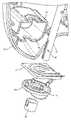
図2を参照すると、連続回転アセンブリ12は、ステータ22と連続的に接触して保持されるローター20を含む。ローター20は、互いに電気的に分離された導電性ピン24および26の第一および第二のセットを担う。ステータ22は、互いに電気的に分離され、それぞれ第一および第二のピンのセット24および26とそれぞれ嵌合するように整列される第一および第二のリング28および30を支持する。例えば、第一および第二のリング28は、シャフト18の周りに同心円状に位置付けら得る。ステータ22は、ハウジング32の内部内に形成された第一のリブ34によってなど、装置10のハウジング32内に固定される。ローター20は、それと回転するためにジョー14を支持する装置10のシャフト18に連結される。例えば、シャフト18は、ローター20のタング38を収容し、シャフト18が回転する場合にローター20に回転力を付与するスロット36を含み得る。 Referring to FIG. 2, continuously rotating assembly 12 includes
図2に示されるように、第一のピンのセット24は、第一のリング28と接触するように位置付けられる。第二のピンのセット26は、第二のリング30に接触するように位置付けられる。第一および第二のピンのセット24および26は、ステータ22に対するローター20の任意の回転中に、第一および第二のリング28および30との安定した電気的接触を維持するばね式先端を有するポゴピンであることが好ましい。ベアリング40は、ハウジング32内で第二のリブ42に対して、また導電リング28および30に対応して第一および第二のピンのセット24および26の間の接触が保持されるように、ローター20をステータ22と接触したままにするようにローター20に対して当接して位置付けられ得る。 As shown in FIG. 2, the first pin set 24 is positioned in contact with the first ring 28 . A second set of
第一のワイヤの対46および48は、接触パッド50を介して、第一および第二のピンのセット24および26にそれぞれ連結され得る。ワイヤ46および48は、シャフト18内に延在し、ジョー14内に保持された電極に接続する。第一のワイヤの対46および48は、ローター20およびシャフト18と共に回転し、そのため、シャフト18のいかに回転するかに関するいかなる張力も受けない。第二のワイヤのセット52および54は、リング28および30のそれぞれを電気外科手術電源16に相互接続する。結果として、電気外科手術電源16は、切断および凝固処置のために、ジョー14に電気的に相互接続される。装置10のシャフト18が電気外科手術処置中に長手方向軸X-Xの周りを回転する場合、ローター20は、ステータ22が静止したまま、シャフト18と共に回転する。ローター20の第一および第二のピンのセット24および26は、任意の回転の間、それぞれリング28および30と接触し続ける。ステータ22が定位置に固定されているため、ワイヤ52および54は、シャフト18の回転と共に移動または伸張する必要がなく、そのためシャフト18がどのように回転しても意図せず外れることはない。結果として、ジョー14と電気外科手術電源16との間の電気的連続性は、シャフト18の回転の程度にかかわらず維持される。事実、シャフト18は、断線や電気部品による電気的連続性の喪失の懸念なく、ジョー14と電気外科手術電源16との間の電気的連結を維持したまま、連続的に回転され得る。 A
Claims (13)
Translated fromJapanese長手方向軸の周りの回転のためにシャフトによって支持される電気外科手術器具、
前記シャフトの周りに位置付けられかつ回転に対して固定されたステータであって、互いに電気的に分離されかつ電気外科手術電源への接続のために構成される同心円状に位置付けられた一対のリングを含む、ステータ、および、
互いに電気的に分離されかつ前記電気外科手術器具に電気的に連結された第一の一組のピンおよび第二の一組のピンを有するローターを含み、
前記第一の一組のピンは同一円状に位置付けられており、前記第二の一組のピンは同一円状に位置付けられており、
前記第一の一組のピンが前記一対のリングのうちの一方と接触して位置付けられ、前記第二の一組のピンが前記一対のリングのうちの他方と接触して位置付けられるように、前記ローターが前記シャフトの周りに位置付けられかつ回転可能である、電気外科手術装置。An electrosurgical device comprising:
an electrosurgical instrument supported by a shaft for rotation about a longitudinal axis;
A stator positioned about said shaftand fixed against rotation,a pair of concentrically positioned rings electrically isolated fromeach otherand configured for connection to an electrosurgical power supply. a stator, and
a rotorhavinga first set of pins and a second set of pins electrically isolated from each otherand electrically coupled to the electrosurgical instrument;
said first set of pins being positioned on the same circle and said second set of pins being positioned on the same circle;
such that the first set of pins is positioned in contact with one of the pair of rings and the secondset of pins is positioned in contact with the otherof the pair of rings; An electrosurgical apparatus,wherein the rotor is positioned and rotatable about the shaft.
互いに電気的に分離されかつ同心円状に位置付けられた第一の一組のピンおよび第二の一組のピンを有するローターの、前記第一の一組のピンが、回転に対して固定されたステータの同心円状に位置付けられた一対のリングの一方と接触して位置付けられ、前記第二の一組のピンが、前記一対のリングの他方と接触して位置付けられるように、前記ローターを前記電気外科手術装置の回転可能シャフトに連結するステップ、
一対の第一のワイヤの一方が前記第一の一組のピンを、前記一対の第一のワイヤの他方が前記第二の一組のピンを、それぞれ前記シャフトに取り付けられた前記電気外科手術装置の電気外科手術器具に連結するステップ、および、
電気外科手術電源が前記電気外科手術器具と電気的に連続するように、一対の第二のワイヤの一方が前記ステータの前記一対のリングの一方を、前記一対の第二のワイヤの他方が前記一対のリングの他方を、それぞれ前記電気外科手術電源に連結するステップを含む、方法。A method of operating an electrosurgical device that provides continuous rotation , comprising:
The first set of pins of a rotor having a first set of pins and a second set of pins electrically isolated from each other and concentrically positioned are fixed against rotation.The rotor is positioned in contact with oneof a pair of concentrically positioned rings of a stator, and the secondset of pins is positioned in contact with the other of the pair of rings. coupling to a rotatable shaft of a surgical device;
one of the pair of first wires attached to the first set of pins and the other of the pair of first wires attached to the shaft to attach the second set of pins, respectively. connecting to an electrosurgical instrument of the device; and
One of the second pair of wires connects oneof the pair of rings of the stator andthe other of the second pair of wires connects the stator so that an electrosurgical power supply is in electrical communication with the electrosurgical instrument. A methodcomprising coupling the other of a pair of rings, respectively, to the electrosurgical power source.
Applications Claiming Priority (3)
| Application Number | Priority Date | Filing Date | Title |
|---|---|---|---|
| US201862749841P | 2018-10-24 | 2018-10-24 | |
| US62/749,841 | 2018-10-24 | ||
| PCT/US2019/057788WO2020086801A1 (en) | 2018-10-24 | 2019-10-24 | Continuous rotation of a surgical instrument |
Publications (2)
| Publication Number | Publication Date |
|---|---|
| JP2022505568A JP2022505568A (en) | 2022-01-14 |
| JP7138786B2true JP7138786B2 (en) | 2022-09-16 |
Family
ID=68582377
Family Applications (1)
| Application Number | Title | Priority Date | Filing Date |
|---|---|---|---|
| JP2021521955AActiveJP7138786B2 (en) | 2018-10-24 | 2019-10-24 | Continuous rotation of surgical instruments |
Country Status (9)
| Country | Link |
|---|---|
| US (1) | US20210393318A1 (en) |
| EP (1) | EP3870089B1 (en) |
| JP (1) | JP7138786B2 (en) |
| KR (1) | KR102558687B1 (en) |
| CN (1) | CN112888392B (en) |
| AU (1) | AU2019365225B2 (en) |
| CA (1) | CA3115542C (en) |
| ES (1) | ES2923275T3 (en) |
| WO (1) | WO2020086801A1 (en) |
Citations (7)
| Publication number | Priority date | Publication date | Assignee | Title |
|---|---|---|---|---|
| JP2002127074A (en) | 2000-10-17 | 2002-05-08 | Alps Electric Co Ltd | Connecting unit for turning angle sensor and actuator using this connecting unit |
| JP2006062019A (en) | 2004-08-26 | 2006-03-09 | Sharp Corp | Robot hand |
| JP2012070857A (en) | 2010-09-28 | 2012-04-12 | Terumo Corp | Medical manipulator |
| WO2012132860A1 (en) | 2011-03-28 | 2012-10-04 | オリンパスメディカルシステムズ株式会社 | Ultrasound therapy device |
| JP2014236984A (en) | 2012-03-19 | 2014-12-18 | オリンパスメディカルシステムズ株式会社 | Gripping treatment device |
| JP2017513566A (en) | 2014-03-26 | 2017-06-01 | エシコン・エンド−サージェリィ・エルエルシーEthicon Endo−Surgery, LLC | Surgical instruments utilizing sensor adaptation |
| JP2017513560A (en) | 2014-03-26 | 2017-06-01 | エシコン・エンド−サージェリィ・エルエルシーEthicon Endo−Surgery, LLC | Feedback algorithm of surgical instrument manual escape system |
Family Cites Families (19)
| Publication number | Priority date | Publication date | Assignee | Title |
|---|---|---|---|---|
| GB1108616A (en)* | 1965-08-25 | 1968-04-03 | Oliver Pell Control Ltd | Improvements in or relating to intermittently operated power-driven mechanisms |
| US3940199A (en)* | 1975-01-23 | 1976-02-24 | Oscar Frederick Ecklund | Rotary contactor for thermocouples |
| US7951071B2 (en)* | 1999-06-02 | 2011-05-31 | Tyco Healthcare Group Lp | Moisture-detecting shaft for use with an electro-mechanical surgical device |
| JP3984119B2 (en)* | 2002-08-06 | 2007-10-03 | オリンパス株式会社 | Lens shutter device |
| US20090198272A1 (en)* | 2008-02-06 | 2009-08-06 | Lawrence Kerver | Method and apparatus for articulating the wrist of a laparoscopic grasping instrument |
| US8852183B2 (en)* | 2009-06-05 | 2014-10-07 | Microline Surgical Inc. | Scissor tip for bipolar high frequency endoscope |
| US10959769B2 (en)* | 2010-11-05 | 2021-03-30 | Ethicon Llc | Surgical instrument with slip ring assembly to power ultrasonic transducer |
| WO2013119545A1 (en)* | 2012-02-10 | 2013-08-15 | Ethicon-Endo Surgery, Inc. | Robotically controlled surgical instrument |
| JP5883343B2 (en)* | 2012-04-12 | 2016-03-15 | 株式会社スズキプレシオン | Medical manipulator |
| US9351754B2 (en)* | 2012-06-29 | 2016-05-31 | Ethicon Endo-Surgery, Llc | Ultrasonic surgical instruments with distally positioned jaw assemblies |
| GB201418486D0 (en)* | 2014-10-17 | 2014-12-03 | Creo Medical Ltd | Cable for conveying radiofrequency and/or microwave frequency energy to an electrosurgical instrument |
| US10245095B2 (en)* | 2015-02-06 | 2019-04-02 | Ethicon Llc | Electrosurgical instrument with rotation and articulation mechanisms |
| US10376302B2 (en)* | 2015-02-18 | 2019-08-13 | Medtronic Xomed, Inc. | Rotating electrical connector for RF energy enabled tissue debridement device |
| US11134968B2 (en)* | 2015-03-16 | 2021-10-05 | Cilag Gmbh International | Surgical jaw coupling methods and devices |
| US20160270842A1 (en)* | 2015-03-20 | 2016-09-22 | Ethicon Endo-Surgery, Llc | Electrosurgical device having controllable current paths |
| US11045223B2 (en)* | 2015-12-11 | 2021-06-29 | Reach Surgical, Inc. | Modular signal interface system and powered trocar |
| CA3011531A1 (en)* | 2016-02-01 | 2017-08-10 | E-Vision Smart Optics, Inc. | Prism-enhanced lenses and methods of using prism-enhanced lenses |
| US20180256241A1 (en)* | 2017-03-08 | 2018-09-13 | Memic Innovative Surgery Ltd. | Monopolar and bipolar electrosurgery device |
| US11564686B2 (en)* | 2017-06-28 | 2023-01-31 | Cilag Gmbh International | Surgical shaft assemblies with flexible interfaces |
- 2019
- 2019-10-24JPJP2021521955Apatent/JP7138786B2/enactiveActive
- 2019-10-24USUS17/288,022patent/US20210393318A1/enactivePending
- 2019-10-24CNCN201980069877.7Apatent/CN112888392B/enactiveActive
- 2019-10-24WOPCT/US2019/057788patent/WO2020086801A1/ennot_activeCeased
- 2019-10-24AUAU2019365225Apatent/AU2019365225B2/enactiveActive
- 2019-10-24ESES19804955Tpatent/ES2923275T3/enactiveActive
- 2019-10-24EPEP19804955.3Apatent/EP3870089B1/enactiveActive
- 2019-10-24KRKR1020217012330Apatent/KR102558687B1/enactiveActive
- 2019-10-24CACA3115542Apatent/CA3115542C/enactiveActive
Patent Citations (7)
| Publication number | Priority date | Publication date | Assignee | Title |
|---|---|---|---|---|
| JP2002127074A (en) | 2000-10-17 | 2002-05-08 | Alps Electric Co Ltd | Connecting unit for turning angle sensor and actuator using this connecting unit |
| JP2006062019A (en) | 2004-08-26 | 2006-03-09 | Sharp Corp | Robot hand |
| JP2012070857A (en) | 2010-09-28 | 2012-04-12 | Terumo Corp | Medical manipulator |
| WO2012132860A1 (en) | 2011-03-28 | 2012-10-04 | オリンパスメディカルシステムズ株式会社 | Ultrasound therapy device |
| JP2014236984A (en) | 2012-03-19 | 2014-12-18 | オリンパスメディカルシステムズ株式会社 | Gripping treatment device |
| JP2017513566A (en) | 2014-03-26 | 2017-06-01 | エシコン・エンド−サージェリィ・エルエルシーEthicon Endo−Surgery, LLC | Surgical instruments utilizing sensor adaptation |
| JP2017513560A (en) | 2014-03-26 | 2017-06-01 | エシコン・エンド−サージェリィ・エルエルシーEthicon Endo−Surgery, LLC | Feedback algorithm of surgical instrument manual escape system |
Also Published As
| Publication number | Publication date |
|---|---|
| CA3115542C (en) | 2023-04-25 |
| AU2019365225B2 (en) | 2022-06-30 |
| AU2019365225A1 (en) | 2021-05-20 |
| KR20210069065A (en) | 2021-06-10 |
| EP3870089B1 (en) | 2022-06-15 |
| CN112888392B (en) | 2024-06-28 |
| CN112888392A (en) | 2021-06-01 |
| JP2022505568A (en) | 2022-01-14 |
| KR102558687B1 (en) | 2023-07-24 |
| CA3115542A1 (en) | 2020-04-30 |
| ES2923275T3 (en) | 2022-09-26 |
| WO2020086801A1 (en) | 2020-04-30 |
| US20210393318A1 (en) | 2021-12-23 |
| EP3870089A1 (en) | 2021-09-01 |
Similar Documents
| Publication | Publication Date | Title |
|---|---|---|
| US6955676B2 (en) | Shaped scalpel | |
| US8734476B2 (en) | Coupling for slip ring assembly and ultrasonic transducer in surgical instrument | |
| US20010000531A1 (en) | Electrocauterizing tool for orthopedic shave devices | |
| RU2014145014A (en) | ELECTRICAL CONNECTION FOR ULTRASONIC SURGICAL INSTRUMENTS COMPLETE WITH ROTATION OPTION | |
| CN109009414B (en) | Surgical instrument and end effector thereof | |
| CN104519820A (en) | Electrosurgical instrument and system | |
| JP7138786B2 (en) | Continuous rotation of surgical instruments | |
| JP2019524275A (en) | Ultrasonic surgical device with reduced electrical interference | |
| CN217447937U (en) | Ultrasonic scalpel | |
| CN113876414A (en) | Slip ring contact assembly for electrosurgical instrument | |
| CN219000543U (en) | Bipolar electric surgical knife | |
| US20080269736A1 (en) | Autoclaveable handle with stripping mechanism to attach a disposable connecting cable | |
| US7601151B2 (en) | Endoscopic high-frequency treatment tool | |
| US20240407798A1 (en) | Treatment instrument with vibration generating device | |
| CN112043372A (en) | High-frequency electric knife | |
| JP3772039B2 (en) | Surgical device | |
| JP4388339B2 (en) | Ultrasonic treatment device | |
| CN112237476A (en) | High-frequency electric knife |
Legal Events
| Date | Code | Title | Description |
|---|---|---|---|
| A621 | Written request for application examination | Free format text:JAPANESE INTERMEDIATE CODE: A621 Effective date:20210422 | |
| A977 | Report on retrieval | Free format text:JAPANESE INTERMEDIATE CODE: A971007 Effective date:20220405 | |
| A131 | Notification of reasons for refusal | Free format text:JAPANESE INTERMEDIATE CODE: A131 Effective date:20220419 | |
| A521 | Request for written amendment filed | Free format text:JAPANESE INTERMEDIATE CODE: A523 Effective date:20220714 | |
| TRDD | Decision of grant or rejection written | ||
| A01 | Written decision to grant a patent or to grant a registration (utility model) | Free format text:JAPANESE INTERMEDIATE CODE: A01 Effective date:20220830 | |
| A61 | First payment of annual fees (during grant procedure) | Free format text:JAPANESE INTERMEDIATE CODE: A61 Effective date:20220906 | |
| R150 | Certificate of patent or registration of utility model | Ref document number:7138786 Country of ref document:JP Free format text:JAPANESE INTERMEDIATE CODE: R150 | |
| R250 | Receipt of annual fees | Free format text:JAPANESE INTERMEDIATE CODE: R250 |