JP7138449B2 - Parts accumulator - Google Patents
Parts accumulatorDownload PDFInfo
- Publication number
- JP7138449B2 JP7138449B2JP2018033019AJP2018033019AJP7138449B2JP 7138449 B2JP7138449 B2JP 7138449B2JP 2018033019 AJP2018033019 AJP 2018033019AJP 2018033019 AJP2018033019 AJP 2018033019AJP 7138449 B2JP7138449 B2JP 7138449B2
- Authority
- JP
- Japan
- Prior art keywords
- parts
- hose
- component
- stacking
- central member
- Prior art date
- Legal status (The legal status is an assumption and is not a legal conclusion. Google has not performed a legal analysis and makes no representation as to the accuracy of the status listed.)
- Active
Links
Images


Classifications
- B—PERFORMING OPERATIONS; TRANSPORTING
- B65—CONVEYING; PACKING; STORING; HANDLING THIN OR FILAMENTARY MATERIAL
- B65G—TRANSPORT OR STORAGE DEVICES, e.g. CONVEYORS FOR LOADING OR TIPPING, SHOP CONVEYOR SYSTEMS OR PNEUMATIC TUBE CONVEYORS
- B65G47/00—Article or material-handling devices associated with conveyors; Methods employing such devices
- B65G47/02—Devices for feeding articles or materials to conveyors
- B65G47/04—Devices for feeding articles or materials to conveyors for feeding articles
- B65G47/12—Devices for feeding articles or materials to conveyors for feeding articles from disorderly-arranged article piles or from loose assemblages of articles
- B65G47/14—Devices for feeding articles or materials to conveyors for feeding articles from disorderly-arranged article piles or from loose assemblages of articles arranging or orientating the articles by mechanical or pneumatic means during feeding
- B65G47/1407—Devices for feeding articles or materials to conveyors for feeding articles from disorderly-arranged article piles or from loose assemblages of articles arranging or orientating the articles by mechanical or pneumatic means during feeding the articles being fed from a container, e.g. a bowl
- B65G47/1442—Devices for feeding articles or materials to conveyors for feeding articles from disorderly-arranged article piles or from loose assemblages of articles arranging or orientating the articles by mechanical or pneumatic means during feeding the articles being fed from a container, e.g. a bowl by means of movement of the bottom or a part of the wall of the container
- B65G47/145—Jigging or reciprocating movement
- B—PERFORMING OPERATIONS; TRANSPORTING
- B65—CONVEYING; PACKING; STORING; HANDLING THIN OR FILAMENTARY MATERIAL
- B65G—TRANSPORT OR STORAGE DEVICES, e.g. CONVEYORS FOR LOADING OR TIPPING, SHOP CONVEYOR SYSTEMS OR PNEUMATIC TUBE CONVEYORS
- B65G27/00—Jigging conveyors
- B65G27/02—Jigging conveyors comprising helical or spiral channels or conduits for elevation of materials
- B—PERFORMING OPERATIONS; TRANSPORTING
- B65—CONVEYING; PACKING; STORING; HANDLING THIN OR FILAMENTARY MATERIAL
- B65G—TRANSPORT OR STORAGE DEVICES, e.g. CONVEYORS FOR LOADING OR TIPPING, SHOP CONVEYOR SYSTEMS OR PNEUMATIC TUBE CONVEYORS
- B65G27/00—Jigging conveyors
- B65G27/10—Applications of devices for generating or transmitting jigging movements
- B65G27/16—Applications of devices for generating or transmitting jigging movements of vibrators, i.e. devices for producing movements of high frequency and small amplitude
- B—PERFORMING OPERATIONS; TRANSPORTING
- B65—CONVEYING; PACKING; STORING; HANDLING THIN OR FILAMENTARY MATERIAL
- B65G—TRANSPORT OR STORAGE DEVICES, e.g. CONVEYORS FOR LOADING OR TIPPING, SHOP CONVEYOR SYSTEMS OR PNEUMATIC TUBE CONVEYORS
- B65G47/00—Article or material-handling devices associated with conveyors; Methods employing such devices
- B65G47/02—Devices for feeding articles or materials to conveyors
- B65G47/04—Devices for feeding articles or materials to conveyors for feeding articles
- B65G47/12—Devices for feeding articles or materials to conveyors for feeding articles from disorderly-arranged article piles or from loose assemblages of articles
- B65G47/14—Devices for feeding articles or materials to conveyors for feeding articles from disorderly-arranged article piles or from loose assemblages of articles arranging or orientating the articles by mechanical or pneumatic means during feeding
- B65G47/1407—Devices for feeding articles or materials to conveyors for feeding articles from disorderly-arranged article piles or from loose assemblages of articles arranging or orientating the articles by mechanical or pneumatic means during feeding the articles being fed from a container, e.g. a bowl
- B65G47/1414—Devices for feeding articles or materials to conveyors for feeding articles from disorderly-arranged article piles or from loose assemblages of articles arranging or orientating the articles by mechanical or pneumatic means during feeding the articles being fed from a container, e.g. a bowl by means of movement of at least the whole wall of the container
- B65G47/1421—Vibratory movement
Landscapes
- Engineering & Computer Science (AREA)
- Mechanical Engineering (AREA)
- Feeding Of Articles To Conveyors (AREA)
- Jigging Conveyors (AREA)
Description
Translated fromJapanese本発明は、部品生産ラインの所定の2つの工程の間に設置され、その上流側工程から排出される部品を集積し、下流側工程に供給する部品集積装置に関する。 The present invention relates to a parts stacking apparatus installed between two predetermined processes of a parts production line, stacking parts discharged from the upstream process, and supplying them to the downstream process.
転がり軸受のころ等、比較的小さな部品を生産する部品生産ラインでは、連続する2つの工程の間に、その上流側工程から排出される部品を一旦集積した後、下流側工程に自動的に供給する部品集積装置として、振動式ボウルフィーダ(「パーツフィーダ」とも呼ばれる。)が設置されることがある。 In parts production lines that produce relatively small parts such as rollers for rolling bearings, parts discharged from the upstream process are once accumulated between two consecutive processes and then automatically supplied to the downstream process. A vibrating bowl feeder (also called a "parts feeder") is sometimes installed as a parts stacking device.
一般的な振動式ボウルフィーダは、内周壁に螺旋状の搬送路が形成されたボウルと、ボウルが取り付けられる上部振動体と、上部振動体の下方に設置される基台と、ボウルの周方向に等間隔で配され、上部振動体と基台とを連結する複数の傾斜板ばねと、上部振動体と基台との間に設けられる加振機構とで基本的に構成され、その加振機構から上部振動体を介してボウルに付与されるねじり振動によって、ボウルの底部に集積された部品をボウルの螺旋状搬送路に沿って搬送し、ボウルの上部から下流側工程に供給するようになっている。 A general vibratory bowl feeder consists of a bowl with a spiral conveying path formed on the inner peripheral wall, an upper vibrating body to which the bowl is attached, a base installed below the upper vibrating body, and a It is basically composed of a plurality of inclined leaf springs arranged at equal intervals and connecting the upper vibrating body and the base, and a vibration mechanism provided between the upper vibrating body and the base. Parts accumulated at the bottom of the bowl are conveyed along the spiral conveying path of the bowl by the torsional vibration imparted to the bowl from the mechanism via the upper vibrating body, and are supplied from the upper part of the bowl to downstream processes. It's becoming
また、振動式ボウルフィーダには、ボウルの搬送路の表面に摩擦材層を設けることにより、搬送路表面と部品との間の摩擦係数を大きくして、部品の搬送能力を向上させ、下流側工程への部品供給能力を確保できるようにしているものもある(例えば、特許文献1参照。)。 In the vibrating bowl feeder, a friction material layer is provided on the surface of the conveying path of the bowl to increase the coefficient of friction between the conveying path surface and the parts, thereby improving the conveying ability of the parts. Some of them are designed to ensure the ability to supply parts to the process (see, for example, Patent Literature 1).
ところが、上記のような振動式ボウルフィーダは、部品供給能力の面では十分な性能を有していても、上流側工程および下流側工程が加工工程である場合、下流側工程の加工方法等によっては、以下に述べるように部品の品質を低下させてしまうおそれがあった。 However, even if the vibrating bowl feeder as described above has sufficient performance in terms of parts supply capacity, if the upstream process and the downstream process are processing processes, the processing method of the downstream process etc. However, there is a possibility that the quality of the parts may be degraded as described below.
まず、振動式ボウルフィーダの下流側の工程でスルーフィード加工方式による加工を行う場合について説明する。スルーフィード加工方式の加工機としては、例えば、図6に示すようなセンタレス研削盤や、図7(a)、(b)に示すような超仕上げ機がある。 First, the case where processing by the through-feed processing method is performed in the downstream process of the vibratory bowl feeder will be described. Examples of through-feed processing machines include a centerless grinder as shown in FIG. 6 and a superfinishing machine as shown in FIGS. 7(a) and 7(b).
図6のセンタレス研削盤は、円筒状の砥石51と調整車52を、それぞれの軸心が相対的にわずかに傾斜するように並べて配置し、同じ方向に回転させることにより、その砥石51と調整車52の間に連続的に送り込まれる転がり軸受の外輪Aをブレード53で支持して軸方向に送りながら、外輪A外周面へ砥石51を押し付けて外輪Aの外径研削を行うものである。 In the centerless grinder shown in FIG. 6, a
また、図7の超仕上げ機は、一対のフィードロール54、55を、図6の砥石51と調整車52の場合と同様の位置関係で配置し、同じ方向に回転させることにより、両フィードロール54、55間に連続的に送り込まれる針状ころBを軸方向に送りながら、針状ころBの外周面へ板状の砥石56を押し当てた状態で、砥石56を針状ころBの送り方向に揺動させることにより、針状ころBの外径面を超仕上げ加工するものである。なお、砥石56は、エアシリンダ57のロッド57aの下端に取り付けられた状態で砥石ホルダ58に上下方向移動可能に支持されており、そのエアシリンダ57の作動によって上下動し、エアシリンダ57および砥石ホルダ58と一体に揺動するようになっている。 In the superfinishing machine of FIG. 7, a pair of
このようなスルーフィード加工方式の加工機は、連続的に送り込まれる被加工物に砥石を押し付けて、同時に複数個の被加工物の加工を行うことができるため、生産性が非常に高いという特長がある。 This type of through-feed processing machine is characterized by extremely high productivity because it can process multiple workpieces at the same time by pressing the grindstone against the workpieces that are continuously fed. There is
一方、一般的な加工設備では、それ自体から発生する熱(加工熱、モータやスピンドル等の構成部品から発生する熱)や、雰囲気温度、クーラント温度等の影響を受けて膨張したり収縮したりするため、砥石等の加工具と被加工物との位置関係が変化し(この現象を「温度ドリフト」と呼ぶ。)、結果的に加工順列とともに加工寸法が徐々に変化していくことが多い。 On the other hand, in general processing equipment, it expands and contracts due to the heat generated by itself (processing heat, heat generated from components such as motors and spindles), ambient temperature, coolant temperature, etc. As a result, the positional relationship between a processing tool such as a grindstone and the workpiece changes (this phenomenon is called "temperature drift"), and as a result, the processing dimensions often change gradually along with the processing order. .
そして、振動式ボウルフィーダでは、上流側工程から排出された部品を、ランダムに(上流側工程での加工順列とは無関係に)ボウル底部に集積した後、1個ずつ下流側工程に供給するため、振動式ボウルフィーダの下流側の工程では上流側の工程とは異なる加工順列で部品の加工が行われることになる。In the vibratory bowl feeder, the parts discharged from the upstream process are randomly accumulated on the bottom of the bowl (regardless of the processing order in the upstream process), and then supplied one by one to the downstream process. In the downstream process of the vibrating bowl feeder, parts are processed in a different processing sequence from the upstream process.
したがって、振動式ボウルフィーダの下流側にスルーフィード加工方式の加工機が接続されている場合、その下流側の加工機では、同時に加工される部品(被加工物)の間で加工前の寸法誤差のバラツキが大きくなるので、部品と砥石との間の面圧のバラツキも大きくなり、加工精度が低下して、一部の部品で加工後の寸法や表面性状が許容範囲から外れるおそれがある。 Therefore, if a through-feed processing machine is connected to the downstream side of the vibrating bowl feeder, the dimensional error before processing between the parts (workpieces) that are processed at the same time in the processing machine on the downstream side , the surface pressure between the parts and the grinding wheel also varies, reducing the machining accuracy and possibly causing the dimensions and surface properties of some parts to fall outside the permissible range.
また、振動式ボウルフィーダでは、搬送中の部品が、振動によって、あるいは姿勢不良のために排除されて、搬送路からボウル底部へ落下し、落下した部品がボウル底部の部品に衝突することにより、両方の部品に打ちキズ等が発生し、製品となった部品の外観品質に悪影響を与えるおそれもある。 In the vibrating bowl feeder, the parts being transported are removed by vibration or due to poor posture and fall from the transport path to the bottom of the bowl. There is also a possibility that bruises or the like may occur on both parts, adversely affecting the appearance quality of the finished parts.
そこで、本発明は、上流側工程から排出された部品を、上流側工程での順列を保持したまま集積し、表面キズを発生させることなく搬送して、下流側工程に供給できる部品集積装置を提供することを課題とする。 Therefore, the present invention provides a component stacking apparatus that stacks components discharged from an upstream process while maintaining the order in the upstream process, conveys them without causing surface scratches, and supplies them to a downstream process. The task is to provide
上記の課題を解決するために、本発明は、部品生産ラインの所定の2つの工程の間に設置され、その2つの工程のうちの上流側工程から排出される部品を集積し、下流側工程に供給する部品集積装置において、前記上流側工程の部品排出口に一端部を接続され、前記下流側工程の部品供給口に他端部を接続されるホースを、円筒状の中心部材の外周と内周の少なくとも一方に螺旋状に配置してなる部品集積部と、前記部品集積部に前記中心部材の軸心まわりのねじり振動を付与する振動発生部とを備え、前記ホースは、その内径が所定の姿勢の部品を1個だけ通過可能とする寸法に形成されており、前記上流側工程の部品排出口から排出された部品が、所定の姿勢で1個ずつ前記ホースの一端部に進入し、前記部品集積部のねじり振動によって前記ホース内を搬送されていき、進入時と同じ順番で前記ホースの他端部から前記下流側工程の部品供給口に供給される構成を採用した。 In order to solve the above problems, the present invention is installed between two predetermined processes of a parts production line, accumulates parts discharged from the upstream process of the two processes, and collects the parts discharged from the downstream process. , a hose having one end connected to the parts discharge port of the upstream process and the other end connected to the parts supply port of the downstream process is connected to the outer circumference of the cylindrical central member The hose has a component stacking portion spirally arranged on at least one of its inner circumferences, and a vibration generating portion that imparts torsional vibration about the axis of the central member to the component stacking portion. The size is formed so that only one component having a predetermined posture can pass through, and the components discharged from the component discharge port of the upstream process enter one end of the hose one by one in a predetermined posture. , the components are conveyed through the hose by the torsional vibration of the components stacking section, and are supplied from the other end of the hose to the component supply port of the downstream process in the same order as when entering.
すなわち、部品生産ラインの所定の2つの工程をつなぐホースを、円筒状の中心部材の外周と内周の少なくとも一方に螺旋状に配置して部品集積部とし、そのホースの内径を所定の姿勢の部品が1個だけ通過可能な寸法とし、部品集積部にねじり振動を付与してホース内の部品を搬送する構成とすることにより、上流側工程から排出された部品を、ホース内で上流側工程の順列通りに集積し、部品どうしの衝突による表面キズを発生させることなく搬送して、下流側工程に供給できるようにしたのである。 That is, a hose that connects two predetermined processes of a parts production line is spirally arranged on at least one of the outer circumference and the inner circumference of a cylindrical central member to form a parts stacking portion, and the inner diameter of the hose is set in a predetermined posture. The dimensions are such that only one part can pass through, and torsional vibration is imparted to the part stacking section to transport the parts in the hose. In this way, the parts are stacked in the correct order, transported without causing surface scratches due to collisions between parts, and supplied to the downstream process.
上記の構成において、前記ホースを、前記中心部材の外周と内周の少なくとも一方に着脱可能に配置されているものとすれば、集積・搬送の対象となる部品の種類やサイズが変わった場合にも、変更後の部品に応じた内径のホースに交換するだけで対応でき、段取作業が効率よく行えるようになる。 In the above configuration, if the hose is detachably arranged on at least one of the outer circumference and the inner circumference of the central member, when the type or size of the parts to be stacked and transported changes. can be handled by simply replacing the hose with a hose with an inner diameter that matches the part after the change, making setup work more efficient.
また、前記ホース内に部品とともに潤滑用の液体が供給されるようにすれば、その液体が搬送方向の前後の部品どうしの間に介在するようになり、より確実に部品の表面キズの発生を防止することができる。 Further, if a lubricating liquid is supplied into the hose together with the parts, the liquid will be interposed between the front and rear parts in the conveying direction, thereby more reliably preventing the occurrence of scratches on the surfaces of the parts. can be prevented.
また、前記振動発生部を、前記部品集積部に付与するねじり振動のねじり方向を反転できる構成とすれば、部品を上り方向で搬送するか下り方向で搬送するかを選択できるようになるので、上流側工程および下流側工程を含めたレイアウトの自由度が大きくなる。 Further, if the vibration generating section is configured to be capable of reversing the torsional direction of the torsional vibration imparted to the component stacking section, it becomes possible to select whether to transport the components in the upward direction or the downward direction. The degree of freedom of layout including upstream and downstream processes is increased.
そして、前記振動発生部としては、前記中心部材が取り付けられる上部振動体と、前記上部振動体の下方に設置される基台と、前記中心部材の周方向に所定の間隔で配され、前記上部振動体と基台を連結する複数の弾性部材と、前記上部振動体と基台の間に水平方向の振動を発生させる加振機構とからなるものを採用することができる。 The vibration generating section includes an upper vibrating body to which the central member is attached, a base installed below the upper vibrating body, and arranged at predetermined intervals in the circumferential direction of the central member. It is possible to adopt a structure comprising a plurality of elastic members that connect the vibrating body and the base, and a vibrating mechanism that generates horizontal vibration between the upper vibrating body and the base.
本発明は、前記所定の2つの工程が部品の加工工程である場合に、特に効果的に適用することができる。 The present invention can be applied particularly effectively when the predetermined two processes are part machining processes.
本発明の部品集積装置は、上述したように、所定の姿勢の部品が1個だけ通過可能な内径のホースを、円筒状の中心部材の外周と内周の少なくとも一方に螺旋状に配置して部品集積部とし、その部品集積部にねじり振動を付与してホース内の部品を搬送するようにしたので、上流側工程から排出された部品を、上流側工程の順列を保持したまま集積・搬送して、下流側工程に供給することができる。 As described above, the component stacking apparatus of the present invention has a hose with an inner diameter that allows only one component in a predetermined posture to pass through, and is spirally arranged on at least one of the outer circumference and the inner circumference of a cylindrical central member. A component stacking section is used, and torsional vibration is imparted to the component stacking section to transport the components in the hose. and can be supplied to downstream processes.
したがって、この部品集積装置を設置した部品生産ラインでは、部品集積装置の上流側工程および下流側工程が加工工程である場合、上流側工程で加工設備の温度ドリフト等によって部品の加工寸法が加工順列とともに変化していても、下流側工程で上流側工程と同じ加工順列で部品加工を行えるので、上流側工程の寸法誤差のバラツキが下流側工程の加工精度に及ぼす影響が少なく、加工完了後の部品寸法精度を向上させることができる。 Therefore, in a parts production line in which this parts stacking device is installed, if the upstream process and the downstream process of the parts stacking device are processing processes, the processing dimensions of the parts may change due to the temperature drift of the processing equipment in the upstream process. Even if there is a change in the machining order, the parts can be machined in the downstream process in the same order as the upstream process. Part dimensional accuracy can be improved.
また、本発明の部品集積装置では、部品をホースに通して集積・搬送するので、部品どうしの衝突による表面キズを発生させるおそれがなく、製品となった部品の表面品質の向上も図れる。 In addition, in the component stacking apparatus of the present invention, since components are stacked and transported through a hose, there is no risk of surface scratches due to collisions between components, and the surface quality of finished products can be improved.
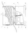
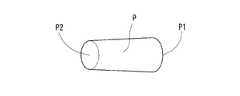
以下、図1乃至図5に基づき、本発明の実施形態を説明する。この部品集積装置は、部品生産ラインの所定の2つの工程の間に設置されるもので、図1乃至図3に示すように、部品集積部1と、部品集積部1の下側面に接続される振動発生部2とからなり、図4に示すように軸方向の一端側P1が他端側P2よりも大径に形成された筒状の部品P、具体的には円錐ころ軸受に組み込まれる円錐ころを集積および搬送の対象としている。そして、図示は省略するが、この部品集積装置の上流側の工程は部品Pの外周面を粗研削する工程であり、部品集積装置の下流側の工程は、部品Pの外周面をスルーフィード加工方式で仕上げ研削する工程である。 An embodiment of the present invention will be described below with reference to FIGS. 1 to 5. FIG. This component stacking apparatus is installed between two predetermined processes of a component production line, and as shown in FIGS. As shown in FIG. 4, one end side P1 in the axial direction is formed to have a larger diameter than the other end side P2. Tapered rollers are targeted for accumulation and transportation. Although illustration is omitted, the upstream process of the component stacking apparatus is a process of rough grinding the outer peripheral surface of the component P, and the downstream process of the component stacking apparatus is through-feed machining of the outer peripheral surface of the component P. It is a process of finish grinding by the method.
前記部品集積部1は、図1乃至図3に示すように、円筒状の中心部材3の外周に樹脂製のホース4を螺旋状に巻き付けた(配置した)もので、中心部材3の外周の上端側から離れていくホース4の一端部が上流側工程の部品排出口(図示省略)に接続され、中心部材3の外周の下端側から離れていくホース4の他端部が下流側工程の部品供給口(図示省略)に接続され、部品Pを下り方向で搬送するようになっている。そのホース4は、中心部材3の上端側および下端側において中心部材3の外周から離れる位置の近傍で、それぞれホース固定具5によって中心部材3に固定されており、各ホース固定具5を取り外すことにより容易に着脱できるようになっている。 As shown in FIGS. 1 to 3, the
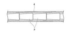
そして、前記ホース4は、図5に示すように、その内径が所定の姿勢(ここでは軸方向をホース4の径方向と直交する方向に向けた姿勢)の部品Pを1個だけ通過可能とする寸法に形成されている。ここで、集積・搬送の対象となる部品の種類やサイズが変われば、ホースの内径も変える必要があるが、上記のようにホースは中心部材の外周に着脱可能に巻き付けているので、部品変更時の段取作業はホースを変更後の部品に応じた内径のものに交換するだけでよく、手間がかからない。 As shown in FIG. 5, the
また、図示は省略するが、ホース4内には部品Pとともに潤滑用の液体として洗浄油や研削クーラント等が供給され、ホース4内の各部品Pがその前後の部品Pとの接触、ホースとの接触による表面キズを生じにくいようになっている。Although not shown, cleaning oil, grindingcoolant , or the like is supplied as a lubricating liquid together with the parts P into the
前記振動発生部2は、一般的な構造の振動式ボウルフィーダのボウルを取り外したもので、図1および図2に示すように、部品集積部1の中心部材3が取り付けられる円板状の上部振動体6と、上部振動体6の下方に設置される基台7と、中心部材3の周方向に所定の間隔で配され、上部振動体6と基台7を連結する複数の弾性部材としての板ばね8とを備えている。各板ばね8は、それぞれ鉛直面に対して同じ角度だけ傾斜した姿勢で、上部振動体6および基台7に取り付けられている。また、上部振動体6の外周には板ばね8を覆う円筒状のカバー9が取り付けられており、基台7は床上に固定された防振ゴム等の防振部材10によって支持されている。 The
そして、図示は省略するが、上部振動体6と基台7の間には水平方向の振動を発生させる加振機構が設けられている。その加振機構は、基台7に取り付けられる交流電磁石と上部振動体6に取り付けられる可動鉄心とからなり、その電磁石と可動鉄心との間に作用する断続的な電磁吸引力によって上部振動体6を振動させるものである。これにより、振動発生部2がその上部振動体6から部品集積部1に中心部材3の軸心まわりのねじり振動を付与し、中心部材3の外周に螺旋状に巻き付けられたホース4の内部を部品Pが搬送されるようになっている。 Although not shown, a vibrating mechanism for generating horizontal vibration is provided between the
なお、この実施形態では部品Pを下り方向で搬送しているが、振動発生部2は加振機構の配置等を変えるだけで、部品集積部1に付与するねじり振動のねじり方向を反転できる構成となっているので、部品Pを上り方向で搬送するように変更することもできる。そして、このように搬送方向を選択できることにより、上流側工程および下流側工程を含めたレイアウトの自由度が大きくなっている。 In this embodiment, the component P is conveyed in the downward direction, but the
この部品集積装置は、上記の構成であり、上流側工程の部品排出口から排出された部品Pが、所定の姿勢で1個ずつホース4の一端部に進入し、部品集積部1のねじり振動によってホース4内を搬送されていき、進入時と同じ順番でホース4の他端部から下流側工程の部品供給口に供給されるようになっている。すなわち、上流側工程から排出された部品Pを、上流側工程の加工順列を保持したまま集積・搬送して、下流側工程に供給することができる。 This component stacking apparatus has the above configuration, and the components P discharged from the component discharge port of the upstream process enter one end of the
したがって、上流側工程で粗研削設備の温度ドリフト等によって部品Pの外径寸法が加工順列とともに変化していても、下流側工程では上流側工程と同じ加工順列で仕上げ研削を行えるので、スルーフィード加工方式の研削機で同時に研削される部品Pは、加工前の寸法誤差のバラツキが小さく、ほぼ同じ面圧で砥石を押し付けられることになる。これにより、従来の振動式ボウルフィーダを用いた場合に比べて、上流側工程での外径寸法誤差のバラツキが下流側工程の研削精度に及ぼす影響が少なくなり、研削完了後の部品Pの外径寸法精度を向上させることができる。 Therefore, even if the outer diameter dimension of the part P changes along with the machining sequence in the upstream process due to the temperature drift of the rough grinding equipment, etc., in the downstream process, finish grinding can be performed in the same machining sequence as the upstream process. The parts P to be ground at the same time by the grinding machine of the processing method have little variation in dimensional error before processing, and can be pressed against the grindstone with substantially the same surface pressure. As a result, compared with the case of using a conventional vibrating bowl feeder, the influence of variation in the outer diameter dimensional error in the upstream process on the grinding accuracy in the downstream process is reduced, and the outer diameter of the part P after grinding is completed. The diameter dimension accuracy can be improved.
また、従来の振動式ボウルフィーダでは、搬送中の部品が搬送路からボウル底部へ落下し、落下した部品とボウル底部の部品の衝突により両方の部品に打ちキズ等が発生することがあるのに対し、この部品集積装置では、部品Pをホース4に通して集積・搬送するので、部品Pどうしの衝突による表面キズを発生させるおそれがなく、また、ホース4内には、前述したように部品Pとともに潤滑用液体が供給されていて部品P同士等の接触も防いでいるので、研削完了後の部品Pの表面品質の向上を図ることもできる。 In addition, in the conventional vibrating bowl feeder, the parts being conveyed fall from the conveying path to the bottom of the bowl, and the dropped parts and the parts at the bottom of the bowl collide with each other, causing scratches on both parts. On the other hand, in this parts stacking apparatus, since the parts P are stacked and transported through the
また、この部品集積装置では、上流側工程から受け入れたすべての部品Pを搬送中に上流側へ戻すことなく下流側工程に供給するので、振動式ボウルフィーダと同等以上の部品供給能力が得られる。 In addition, in this parts stacking apparatus, all the parts P received from the upstream process are supplied to the downstream process without being returned to the upstream side during transportation, so that a parts supply capacity equal to or greater than that of a vibratory bowl feeder can be obtained. .
さらに、全体的な構造としては、一般的な振動式ボウルフィーダのボウルを部品集積部1に代えたものとなっているので、市販の振動式ボウルフィーダの改造により容易に製作することができる。そして、既設の部品生産ラインで工程間の部品搬送にホースを用いた搬送方式を採用している場合は、その工程間の部品搬送用ホースの途中に部品集積部1のホース4を接続するだけで、部品Pの集積・搬送の機能を発揮できるようになるという利点もある。 Furthermore, as for the overall structure, since the bowl of a general vibrating bowl feeder is replaced with the
今回開示された実施の形態はすべての点で例示であって制限的なものではないと考えられるべきである。本発明の範囲は、上記した意味ではなく、特許請求の範囲によって示され、特許請求の範囲と均等の意味および範囲内でのすべての変更が含まれることが意図される。 It should be considered that the embodiments disclosed this time are illustrative in all respects and not restrictive. The scope of the present invention is indicated by the scope of the claims rather than the meaning described above, and is intended to include all modifications within the scope and meaning equivalent to the scope of the claims.
例えば、実施形態の部品集積部は、円筒状の中心部材の外周にホースを螺旋状に巻き付けたものとしたが、そのホースは中心部材の内周に螺旋状に配置してもよいし、中心部材の外周と内周の両方に螺旋状に配置してもよい。 For example, in the component stacking section of the embodiment, the hose is spirally wound around the outer circumference of the cylindrical central member, but the hose may be arranged spirally around the inner circumference of the central member, or It may be spirally arranged on both the outer and inner circumferences of the member.
また、部品集積部では、実施形態のようにホース内に潤滑用の液体を供給することが望ましいが、前後の部品どうしの接触による部品の搬送方向端部の表面キズがあまり問題とならないような場合には、ホース内への液体の供給を行わないようにして構造の簡素化を図ることもできる。 In addition, in the parts stacking section, it is desirable to supply a lubricating liquid to the inside of the hose as in the embodiment. In some cases, the structure can be simplified by not supplying the liquid into the hose.
また、ホースの材質は、実施形態のような樹脂に限らず、金属製のパイプなどの中空状のものを用いることができる。 Further, the material of the hose is not limited to resin as in the embodiment, and a hollow material such as a metal pipe can be used.
また、実施形態では、振動発生部として一般的な振動式ボウルフィーダの一部を利用するようにしたが、振動発生部の構成はこれに限らず、部品集積部にねじり振動を付与することができるようになっていればよい。 Further, in the embodiment, a part of a general vibrating bowl feeder is used as the vibration generator, but the configuration of the vibration generator is not limited to this, and torsional vibration can be applied to the component stacking section. It would be nice if they were able to do so.
そして、本発明は、実施形態で説明したような円錐ころを集積・搬送の対象とする部品集積装置に限らず、各種のころ軸受のころ等で、部品生産ラインの途中でスルーフィード加工方式による加工を受ける部品を対象とし、スルーフィード加工方式による加工を行う工程とその上流側の工程の間に設置される部品集積装置に広く効果的に適用できる。 The present invention is not limited to the component stacking device for stacking and transporting tapered rollers as described in the embodiment, but can also be used for rollers of various types of roller bearings, etc., by the through-feed machining method in the middle of the component production line. The present invention can be widely and effectively applied to a component stacking apparatus installed between a process for processing parts to be processed by the through-feed machining method and an upstream process.
さらに、本発明の部品集積装置は、部品生産ラインの2つの加工工程の間に設置されるだけでなく、検査・搬送・投入等にも使用することができる。 Furthermore, the component stacking apparatus of the present invention can be used not only for installation between two processing steps in a component production line, but also for inspection, transportation, loading, and the like.
1 部品集積部
2 振動発生部
3 中心部材
4 ホース
5 ホース固定具
6 上部振動体
7 基台
8 板ばね
9 カバー
10 防振部材
P 部品(円錐ころ)1
Claims (6)
Translated fromJapanese前記上流側工程の部品排出口に一端部を接続され、前記下流側工程の部品供給口に他端部を接続されるホースを、円筒状の中心部材の外周と内周の少なくとも一方に螺旋状に配置してなる部品集積部と、前記部品集積部に前記中心部材の軸心まわりのねじり振動を付与する振動発生部とを備え、
前記ホースは、その内径が所定の姿勢の部品を1個だけ通過可能とする寸法に形成されており、
前記ホースの一端部と他端部を除く部位は、前記中心部材の軸心方向で隣り合う部分どうしが接触するように配置されており、
前記上流側工程の部品排出口から排出された部品が、所定の姿勢で1個ずつ前記ホースの一端部に進入し、前記部品集積部のねじり振動によって前記ホース内を搬送されていき、進入時と同じ順番で前記ホースの他端部から前記下流側工程の部品供給口に供給されるようになっていることを特徴とする部品集積装置。In a parts stacking apparatus installed between two predetermined processes of a parts production line, stacking parts discharged from an upstream process of the two processes and supplying them to a downstream process,
A hose having one end connected to the parts discharge port of the upstream process and the other end connected to the parts supply port of the downstream process is spirally wound around at least one of the outer circumference and the inner circumference of the cylindrical central member. and a vibration generator that imparts torsional vibration about the axis of the central member to the parts stacking unit,
The hose has an inner diameter that is sized to allow passage of only one component in a predetermined posture,
Parts other than one end and the other end of the hose are arranged so that adjacent parts in the axial direction of the central member are in contact with each other,
The parts discharged from the part discharge port of the upstream process enter one end of the hose one by one in a predetermined posture, and are conveyed in the hose by the torsional vibration of the parts stacking section. A component stacking apparatus, wherein the components are supplied from the other end of the hose to the component supply port of the downstream process in the same order as the above.
Priority Applications (3)
| Application Number | Priority Date | Filing Date | Title |
|---|---|---|---|
| JP2018033019AJP7138449B2 (en) | 2018-02-27 | 2018-02-27 | Parts accumulator |
| US16/970,261US11186440B2 (en) | 2018-02-27 | 2019-02-26 | Parts accumulator |
| PCT/JP2019/007202WO2019167917A1 (en) | 2018-02-27 | 2019-02-26 | Part stacking device |
Applications Claiming Priority (1)
| Application Number | Priority Date | Filing Date | Title |
|---|---|---|---|
| JP2018033019AJP7138449B2 (en) | 2018-02-27 | 2018-02-27 | Parts accumulator |
Publications (2)
| Publication Number | Publication Date |
|---|---|
| JP2019147650A JP2019147650A (en) | 2019-09-05 |
| JP7138449B2true JP7138449B2 (en) | 2022-09-16 |
Family
ID=67804972
Family Applications (1)
| Application Number | Title | Priority Date | Filing Date |
|---|---|---|---|
| JP2018033019AActiveJP7138449B2 (en) | 2018-02-27 | 2018-02-27 | Parts accumulator |
Country Status (3)
| Country | Link |
|---|---|
| US (1) | US11186440B2 (en) |
| JP (1) | JP7138449B2 (en) |
| WO (1) | WO2019167917A1 (en) |
Families Citing this family (1)
| Publication number | Priority date | Publication date | Assignee | Title |
|---|---|---|---|---|
| CN115196367B (en)* | 2022-07-13 | 2023-05-09 | 辽宁傲农饲料有限公司 | Dust removal anti-blocking material vibration lifting device |
Citations (2)
| Publication number | Priority date | Publication date | Assignee | Title |
|---|---|---|---|---|
| JP2009113961A (en) | 2007-11-08 | 2009-05-28 | Abe Tekkosho:Kk | Closed type oscillating vertical transport machine |
| CN206939699U (en) | 2017-07-24 | 2018-01-30 | 新乡市德科筛分机械有限公司 | A kind of vertical vibration hoist |
Family Cites Families (14)
| Publication number | Priority date | Publication date | Assignee | Title |
|---|---|---|---|---|
| JPS5213098Y2 (en)* | 1972-11-14 | 1977-03-24 | ||
| JPS5140346B2 (en) | 1972-12-21 | 1976-11-02 | ||
| JPS5324713B2 (en) | 1974-05-09 | 1978-07-22 | ||
| JPS5328203Y2 (en)* | 1974-05-15 | 1978-07-15 | ||
| US4021902A (en)* | 1976-06-04 | 1977-05-10 | Roland Max G | Coiled vibratory feeder |
| JPS59143808A (en)* | 1983-02-04 | 1984-08-17 | Shinko Electric Co Ltd | Article storing device |
| US4821782A (en)* | 1987-01-29 | 1989-04-18 | Hyer Industries, Inc. | Powder feeder |
| US5143253A (en)* | 1988-09-02 | 1992-09-01 | Tdk Corporation | Chip packaging means and supply mechanism for supplying chips by using the chip packaging means |
| JPH02132019A (en) | 1988-11-10 | 1990-05-21 | Canon Inc | Image forming device |
| JP2909824B2 (en)* | 1989-03-30 | 1999-06-23 | エヌデーシー株式会社 | Posture conversion method and device for half flat bearing |
| DE19925789A1 (en)* | 1999-06-05 | 2000-12-07 | Philips Corp Intellectual Pty | Storage device for components and device with such a storage device |
| AU2001281665A1 (en)* | 2000-10-04 | 2002-04-15 | Kramer Ag Bassersdorf | Self-cleaning oscillating conveyor for deburring, dedusting and the onward transport of small parts |
| US6669435B2 (en)* | 2001-03-28 | 2003-12-30 | Vishay Intertechnology, Inc. | Precision resistor tube feeder |
| FR2983186B1 (en)* | 2011-11-24 | 2014-01-17 | Technical Alliance | HELICOIDAL VIBRATOR TRANSPORT DEVICE |
- 2018
- 2018-02-27JPJP2018033019Apatent/JP7138449B2/enactiveActive
- 2019
- 2019-02-26USUS16/970,261patent/US11186440B2/enactiveActive
- 2019-02-26WOPCT/JP2019/007202patent/WO2019167917A1/ennot_activeCeased
Patent Citations (2)
| Publication number | Priority date | Publication date | Assignee | Title |
|---|---|---|---|---|
| JP2009113961A (en) | 2007-11-08 | 2009-05-28 | Abe Tekkosho:Kk | Closed type oscillating vertical transport machine |
| CN206939699U (en) | 2017-07-24 | 2018-01-30 | 新乡市德科筛分机械有限公司 | A kind of vertical vibration hoist |
Also Published As
| Publication number | Publication date |
|---|---|
| US11186440B2 (en) | 2021-11-30 |
| WO2019167917A1 (en) | 2019-09-06 |
| US20210107742A1 (en) | 2021-04-15 |
| JP2019147650A (en) | 2019-09-05 |
Similar Documents
| Publication | Publication Date | Title |
|---|---|---|
| TWI735649B (en) | Grinding device | |
| JP5675973B2 (en) | Machine for deep rolling of wheelset shaft | |
| KR102458795B1 (en) | Methods and apparatus for profile and surface preparation of retaining rings utilized in chemical mechanical polishing processes | |
| KR20100092873A (en) | Processing method and grinding apparatus for lens | |
| JP7138449B2 (en) | Parts accumulator | |
| KR20070067730A (en) | Equipment for manufacturing ball bearings and superfinishing machines | |
| JP2019130642A (en) | Cylinder polishing device | |
| KR20140029932A (en) | Pipe polishing machine | |
| CN105538125B (en) | A kind of Superfinishing machine supporting mechanism | |
| JP5134863B2 (en) | Manufacturing method of conductive roller | |
| JP2004106149A (en) | Automatic workpiece grinding device and automatic workpiece grinding method | |
| JP7064661B2 (en) | Grinding and polishing grindstone with outer diameter increase / decrease control and grinding / polishing / honing processing method with this outer diameter increase / decrease control grinding and polishing grindstone | |
| CN205325418U (en) | Super smart quick -witted supporting mechanism | |
| KR102458268B1 (en) | Automatic machining system for outer wheel body of wheel bearing assembly | |
| JP2021074840A (en) | Grinding device of angular bearing and carrying method of angular bearing | |
| JP2006297548A (en) | Continuously workable cylindrical grinder | |
| JP2009142957A (en) | Method for manufacturing pipe with flange member | |
| CN107498430A (en) | Numerically control grinder for processed complex curved surface | |
| KR101857587B1 (en) | silicon filament finishing automatic grinding machine with a material rotating method and polishing system using the same | |
| CN207387325U (en) | For the numerically control grinder of processed complex curved surface | |
| JP4142604B2 (en) | Rotating electrical machine shaft, shaft manufacturing method, and shaft grinding apparatus | |
| US20210370374A1 (en) | Burnishing machine | |
| KR100423358B1 (en) | A polishing machine having a adjust idle roller | |
| JPH02250758A (en) | Outer diameter grinding method for disk-shaped work and grinder | |
| JP7210307B2 (en) | Method for manufacturing metal parts |
Legal Events
| Date | Code | Title | Description |
|---|---|---|---|
| A621 | Written request for application examination | Free format text:JAPANESE INTERMEDIATE CODE: A621 Effective date:20210126 | |
| A131 | Notification of reasons for refusal | Free format text:JAPANESE INTERMEDIATE CODE: A131 Effective date:20220111 | |
| A601 | Written request for extension of time | Free format text:JAPANESE INTERMEDIATE CODE: A601 Effective date:20220113 | |
| A521 | Request for written amendment filed | Free format text:JAPANESE INTERMEDIATE CODE: A523 Effective date:20220512 | |
| TRDD | Decision of grant or rejection written | ||
| A01 | Written decision to grant a patent or to grant a registration (utility model) | Free format text:JAPANESE INTERMEDIATE CODE: A01 Effective date:20220809 | |
| A61 | First payment of annual fees (during grant procedure) | Free format text:JAPANESE INTERMEDIATE CODE: A61 Effective date:20220906 | |
| R150 | Certificate of patent or registration of utility model | Ref document number:7138449 Country of ref document:JP Free format text:JAPANESE INTERMEDIATE CODE: R150 | |
| R250 | Receipt of annual fees | Free format text:JAPANESE INTERMEDIATE CODE: R250 |