JP7136997B2 - Automatic retraction with target position selection - Google Patents
Automatic retraction with target position selectionDownload PDFInfo
- Publication number
- JP7136997B2 JP7136997B2JP2021505871AJP2021505871AJP7136997B2JP 7136997 B2JP7136997 B2JP 7136997B2JP 2021505871 AJP2021505871 AJP 2021505871AJP 2021505871 AJP2021505871 AJP 2021505871AJP 7136997 B2JP7136997 B2JP 7136997B2
- Authority
- JP
- Japan
- Prior art keywords
- trailer
- coupler
- vehicle
- user selection
- tow
- Prior art date
- Legal status (The legal status is an assumption and is not a legal conclusion. Google has not performed a legal analysis and makes no representation as to the accuracy of the status listed.)
- Active
Links
Images


Classifications
- G—PHYSICS
- G05—CONTROLLING; REGULATING
- G05D—SYSTEMS FOR CONTROLLING OR REGULATING NON-ELECTRIC VARIABLES
- G05D1/00—Control of position, course, altitude or attitude of land, water, air or space vehicles, e.g. using automatic pilots
- G05D1/02—Control of position or course in two dimensions
- G05D1/021—Control of position or course in two dimensions specially adapted to land vehicles
- G05D1/0212—Control of position or course in two dimensions specially adapted to land vehicles with means for defining a desired trajectory
- G05D1/0225—Control of position or course in two dimensions specially adapted to land vehicles with means for defining a desired trajectory involving docking at a fixed facility, e.g. base station or loading bay
- B—PERFORMING OPERATIONS; TRANSPORTING
- B60—VEHICLES IN GENERAL
- B60D—VEHICLE CONNECTIONS
- B60D1/00—Traction couplings; Hitches; Draw-gear; Towing devices
- B60D1/01—Traction couplings or hitches characterised by their type
- B60D1/06—Ball-and-socket hitches, e.g. constructional details, auxiliary devices, their arrangement on the vehicle
- B—PERFORMING OPERATIONS; TRANSPORTING
- B60—VEHICLES IN GENERAL
- B60D—VEHICLE CONNECTIONS
- B60D1/00—Traction couplings; Hitches; Draw-gear; Towing devices
- B60D1/58—Auxiliary devices
- B60D1/62—Auxiliary devices involving supply lines, electric circuits, or the like
- B—PERFORMING OPERATIONS; TRANSPORTING
- B60—VEHICLES IN GENERAL
- B60W—CONJOINT CONTROL OF VEHICLE SUB-UNITS OF DIFFERENT TYPE OR DIFFERENT FUNCTION; CONTROL SYSTEMS SPECIALLY ADAPTED FOR HYBRID VEHICLES; ROAD VEHICLE DRIVE CONTROL SYSTEMS FOR PURPOSES NOT RELATED TO THE CONTROL OF A PARTICULAR SUB-UNIT
- B60W30/00—Purposes of road vehicle drive control systems not related to the control of a particular sub-unit, e.g. of systems using conjoint control of vehicle sub-units
- B60W30/18—Propelling the vehicle
- B60W30/18009—Propelling the vehicle related to particular drive situations
- B60W30/18036—Reversing
- G—PHYSICS
- G05—CONTROLLING; REGULATING
- G05D—SYSTEMS FOR CONTROLLING OR REGULATING NON-ELECTRIC VARIABLES
- G05D1/00—Control of position, course, altitude or attitude of land, water, air or space vehicles, e.g. using automatic pilots
- G05D1/02—Control of position or course in two dimensions
- G05D1/021—Control of position or course in two dimensions specially adapted to land vehicles
- G05D1/0231—Control of position or course in two dimensions specially adapted to land vehicles using optical position detecting means
- B—PERFORMING OPERATIONS; TRANSPORTING
- B60—VEHICLES IN GENERAL
- B60D—VEHICLE CONNECTIONS
- B60D1/00—Traction couplings; Hitches; Draw-gear; Towing devices
- B60D1/24—Traction couplings; Hitches; Draw-gear; Towing devices characterised by arrangements for particular functions
- B60D1/36—Traction couplings; Hitches; Draw-gear; Towing devices characterised by arrangements for particular functions for facilitating connection, e.g. hitch catchers, visual guide means, signalling aids
- B—PERFORMING OPERATIONS; TRANSPORTING
- B60—VEHICLES IN GENERAL
- B60W—CONJOINT CONTROL OF VEHICLE SUB-UNITS OF DIFFERENT TYPE OR DIFFERENT FUNCTION; CONTROL SYSTEMS SPECIALLY ADAPTED FOR HYBRID VEHICLES; ROAD VEHICLE DRIVE CONTROL SYSTEMS FOR PURPOSES NOT RELATED TO THE CONTROL OF A PARTICULAR SUB-UNIT
- B60W2300/00—Indexing codes relating to the type of vehicle
- B60W2300/14—Tractor-trailers, i.e. combinations of a towing vehicle and one or more towed vehicles, e.g. caravans; Road trains
- B—PERFORMING OPERATIONS; TRANSPORTING
- B60—VEHICLES IN GENERAL
- B60W—CONJOINT CONTROL OF VEHICLE SUB-UNITS OF DIFFERENT TYPE OR DIFFERENT FUNCTION; CONTROL SYSTEMS SPECIALLY ADAPTED FOR HYBRID VEHICLES; ROAD VEHICLE DRIVE CONTROL SYSTEMS FOR PURPOSES NOT RELATED TO THE CONTROL OF A PARTICULAR SUB-UNIT
- B60W2420/00—Indexing codes relating to the type of sensors based on the principle of their operation
- B60W2420/40—Photo, light or radio wave sensitive means, e.g. infrared sensors
- B60W2420/403—Image sensing, e.g. optical camera
- B—PERFORMING OPERATIONS; TRANSPORTING
- B60—VEHICLES IN GENERAL
- B60W—CONJOINT CONTROL OF VEHICLE SUB-UNITS OF DIFFERENT TYPE OR DIFFERENT FUNCTION; CONTROL SYSTEMS SPECIALLY ADAPTED FOR HYBRID VEHICLES; ROAD VEHICLE DRIVE CONTROL SYSTEMS FOR PURPOSES NOT RELATED TO THE CONTROL OF A PARTICULAR SUB-UNIT
- B60W2540/00—Input parameters relating to occupants
- B60W2540/18—Steering angle
- B—PERFORMING OPERATIONS; TRANSPORTING
- B60—VEHICLES IN GENERAL
- B60W—CONJOINT CONTROL OF VEHICLE SUB-UNITS OF DIFFERENT TYPE OR DIFFERENT FUNCTION; CONTROL SYSTEMS SPECIALLY ADAPTED FOR HYBRID VEHICLES; ROAD VEHICLE DRIVE CONTROL SYSTEMS FOR PURPOSES NOT RELATED TO THE CONTROL OF A PARTICULAR SUB-UNIT
- B60W2540/00—Input parameters relating to occupants
- B60W2540/215—Selection or confirmation of options
- B—PERFORMING OPERATIONS; TRANSPORTING
- B60—VEHICLES IN GENERAL
- B60W—CONJOINT CONTROL OF VEHICLE SUB-UNITS OF DIFFERENT TYPE OR DIFFERENT FUNCTION; CONTROL SYSTEMS SPECIALLY ADAPTED FOR HYBRID VEHICLES; ROAD VEHICLE DRIVE CONTROL SYSTEMS FOR PURPOSES NOT RELATED TO THE CONTROL OF A PARTICULAR SUB-UNIT
- B60W2554/00—Input parameters relating to objects
- B60W2554/80—Spatial relation or speed relative to objects
- B60W2554/801—Lateral distance
Landscapes
- Engineering & Computer Science (AREA)
- Transportation (AREA)
- Mechanical Engineering (AREA)
- Automation & Control Theory (AREA)
- Physics & Mathematics (AREA)
- Aviation & Aerospace Engineering (AREA)
- Radar, Positioning & Navigation (AREA)
- Remote Sensing (AREA)
- General Physics & Mathematics (AREA)
- Electromagnetism (AREA)
- Control Of Driving Devices And Active Controlling Of Vehicle (AREA)
- Fittings On The Vehicle Exterior For Carrying Loads, And Devices For Holding Or Mounting Articles (AREA)
- Traffic Control Systems (AREA)
Description
Translated fromJapanese本開示は、選択されたターゲット位置に向かって牽引車両を自動後退させるための方法および装置に関する。 The present disclosure relates to methods and apparatus for automatically reversing a tow vehicle toward a selected target location.
背景技術
トレーラは、一般に、動力を有する牽引車両によって牽引される、動力を有しない車両である。トレーラは、ユーティリティトレーラ、ポップアップ式キャンパ、トラベルトレーラ、家畜トレーラ、平台型トレーラ、閉鎖型カーキャリアおよびボートトレーラなどであってよい。牽引車両は、自動車、クロスオーバ、トラック、バン、SUV(sports-utility-vehicle)、RV(recreational vehicle)またはトレーラに連結されてトレーラを牽引するように構成された別の任意の車両であってよい。トレーラは、トレーラヒッチを使用して、動力を有する車両に連結可能である。受け手側のヒッチは、牽引車両に取り付けられ、連結を形成するためにトレーラヒッチに連結される。トレーラヒッチは、ボールおよびソケット、第五輪およびがん首、またはトレーラジャックであってよい。別の連結機構も使用可能である。いくつかの実施例では、トレーラと、動力を有する車両との間の機械的連結に加え、トレーラは、牽引車両に電気的に接続されている。したがってこの電気的な接続により、トレーラは、動力を有する車両の後方ライト回路から給電されることが可能であり、これにより、トレーラは、動力を有する車両のライトと同期するテールランプ、方向指示器およびブレーキライトを有することができる。BACKGROUND OF THE INVENTION A trailer is generally a non-motorized vehicle that is towed by a motorized towing vehicle. Trailers may be utility trailers, pop-up campers, travel trailers, livestock trailers, flatbed trailers, closed car carriers, boat trailers, and the like. A towing vehicle may be an automobile, crossover, truck, van, sports-utility-vehicle (SUV), recreational vehicle (RV), or any other vehicle coupled to and configured to tow a trailer. good. A trailer is connectable to a powered vehicle using a trailer hitch. The receiver hitch is attached to the tow vehicle and connected to the trailer hitch to form the connection. A trailer hitch may be a ball and socket, a fifth wheel and neck, or a trailer jack. Alternative coupling mechanisms are also available. In some examples, in addition to the mechanical connection between the trailer and the powered vehicle, the trailer is electrically connected to the towing vehicle. This electrical connection thus allows the trailer to be powered from the powered vehicle's rear light circuit, thereby providing the trailer with tail lamps, turn signals and taillights synchronized with the powered vehicle's lights. Can have brake lights.
センサ技術における最近の進歩は、自動運転の改良に結び付いている。したがって、車両をトレーラにヒッチングするためにトレーラに向かって操縦可能な自動車両後退システムを提供することは望ましい。 Recent advances in sensor technology have been linked to improved autonomous driving. Accordingly, it would be desirable to provide an automated vehicle reversing system that is steerable toward a trailer to hitch the vehicle onto the trailer.
概要
本開示の一態様により、牽引車両の後ろに位置付けられたトレーラに向かって牽引車両を自律操縦させる方法が提供される。この方法では、牽引車両の後部に位置付けられかつデータ処理ハードウェアと通信するカメラから、1つ以上の画像をデータ処理ハードウェアにおいて受信する。この方法では、1つ以上の画像内のトレーラ表現の第1ユーザ選択をデータ処理ハードスイッチングにおいて受信する。第1ユーザ選択は、トレーラ表現を取り囲むバウンディングボックスを含んでいてよい。この方法ではまた、トレーラ表現の第1ユーザ選択に関連付けられたトレーラに向かって後方向に牽引車両を自律操縦させる第1命令を、データ処理ハードウェアから、データ処理ハードウェアと通信する運転システムに送信する。この方法ではまた、1つ以上の画像内の、トレーラのトレーラカプラに関連付けられたカプラ表現の第2ユーザ選択をデータ処理ハードウェアにおいて受信する。第2ユーザ選択は、カプラ表現を取り囲むカプラバウンディングボックスを含んでいてよい。この方法では付加的に、カプラ表現の第2ユーザ選択に関連付けられたトレーラカプラに向かって後方向に牽引車両を自律操縦させる第2命令を、データ処理ハードウェアから運転システムに送信する。SUMMARY According to one aspect of the present disclosure, a method is provided for autonomously steering a tow vehicle toward a trailer positioned behind the tow vehicle. In this method, one or more images are received at the data processing hardware from a camera positioned at the rear of the towing vehicle and in communication with the data processing hardware. In the method, a first user selection of trailer representations in one or more images is received in data processing hardswitching. A first user selection may include a bounding box surrounding the trailer representation. The method also includes providing, from the data processing hardware, to an operating system in communication with the data processing hardware a first instruction to autonomously steer the towing vehicle in a rearward direction toward the trailer associated with the first user selection of the trailer representation. Send. The method also receives at the data processing hardware a second user selection of coupler representations associated with trailer couplers of the trailer in the one or more images. A second user selection may include a coupler bounding box surrounding the coupler representation. The method additionally includes sending a second command from the data processing hardware to the operating system to autonomously steer the towing vehicle in a rearward direction toward the trailer coupler associated with the second user selection of the coupler representation.
本開示の複数の実装形態には、1つ以上の以下の選択的な特徴が含まれていてよい。いくつかの実装形態において、この方法では、トレーラ表現の第1ユーザ選択に関連付けられたトレーラに向かって後方向に牽引車両を自律操縦させるのに伴って、1つ以上の画像内でトレーラバウンディングボックスを追跡する。この方法ではまた、カプラ表現の第2ユーザ選択に関連付けられたトレーラカプラに向かって後方向に牽引車両を自律操縦させるのに伴って、1つ以上の画像内でカプラバウンディングボックスを追跡してもよい。いくかの実施例において、この方法では、データ処理ハードウェアと通信するセンサシステムからホイールティックセンサデータおよびステアリングホイール角度データを受信する。この方法では、ホイールティックセンサデータおよびステアリングホイール角度データに基づいて、車両位置を特定し、トレーラおよびカプラに対して相対的な牽引車両位置に基づいて、第1命令および/または第2命令をそれぞれ調整する。 Implementations of the disclosure may include one or more of the following optional features. In some implementations, the method includes moving the trailer bounding box in the one or more images as the tow vehicle autonomously steers backward toward the trailer associated with the first user selection of the trailer representation. track. The method also includes tracking the coupler bounding box in the one or more images as the tow vehicle autonomously steers backward toward the trailer coupler associated with the second user selection of the coupler representation. good. In some embodiments, the method receives wheel tick sensor data and steering wheel angle data from a sensor system in communication with data processing hardware. The method includes determining a vehicle position based on wheel tick sensor data and steering wheel angle data and issuing a first command and/or a second command based on the towing vehicle position relative to the trailer and coupler, respectively. adjust.
いくつかの実装形態において、この方法では、牽引車両の牽引ボールの牽引ボール位置を特定する。後方向に牽引車両が自律操縦する間に、この方法では、牽引ボール位置と、牽引バウンディングボックスまたはカプラバウンディングボックスの中心との間の長手方向距離および横方向距離を特定する。ここでこの中心は、トレーラバウンディングボックスまたはカプラバウンディングボックスの底部の中心である。第1命令および第2命令は、長手方向距離および横方向距離を減少させる。 In some implementations, the method identifies a tow ball location for a tow ball of a tow vehicle. While the tow vehicle autonomously steers in the rearward direction, the method identifies the longitudinal and lateral distances between the tow ball position and the center of the tow bounding box or coupler bounding box. Here this center is the center of the bottom of the trailer bounding box or the coupler bounding box. The first and second instructions decrease the longitudinal distance and the lateral distance.
本開示の別の一態様により、牽引車両の後ろに位置付けられたトレーラに向かってこの牽引車両を自律操縦させるシステムが提供される。このシステムには、データ処理ハードウェアと、このデータ処理ハードウェアと通信するメモリハードウェアとが含まれている。このメモリハードウェアには、データ処理ハードウェア上で実行される場合に、このデータ処理ハードウェアに上述の方法を含む動作を実行させる命令が格納されている。 Another aspect of the present disclosure provides a system for autonomously steering a towing vehicle toward a trailer positioned behind the towing vehicle. The system includes data processing hardware and memory hardware in communication with the data processing hardware. Stored in the memory hardware are instructions which, when executed on the data processing hardware, cause the data processing hardware to perform operations, including the methods described above.
本開示の1つ以上の実装形態の詳細は、添付の図面および以下の説明に記載されている。他の態様、特徴および利点は、説明および図面ならびに特許請求の範囲から明らかになろう。 The details of one or more implementations of the disclosure are set forth in the accompanying drawings and the description below. Other aspects, features and advantages will be apparent from the description and drawings and from the claims.
種々異なる図において同様の参照符号は、同様の要素を示す。 Similar reference numerals in the different figures indicate similar elements.
詳細な説明
自動車、クロスオーバ、トラック、バン、SUV(sports-utility-vehicle)およびRV(recreational vehicle)のような、しかしこれらに限定されない牽引車両は、トレーラを牽引するように構成されていてよい。牽引車両は、トレーラヒッチによってトレーラに連結される。トレーラまでの手動による後退には、運転者の大きな努力が必要になることがある。運転者は、絶えず後方の車両カメラを監視して、車両の牽引ボールがトレーラのカプラの下に来るように車両を操舵しなければならない。したがって、車両の後方の周囲環境の画像から識別されかつユーザディスプレイのようなユーザインタフェースに表示される、運転者によって指定された位置、例えばトレーラに向かって自律的に後退することができる牽引車両を有することが望ましい。DETAILED DESCRIPTION Towing vehicles such as, but not limited to, automobiles, crossovers, trucks, vans, sports-utility-vehicles (SUVs) and recreational vehicles (RVs) may be configured to tow trailers. . A tow vehicle is coupled to the trailer by a trailer hitch. Manual reversing to the trailer may require significant driver effort. The driver must constantly monitor the rear vehicle camera and steer the vehicle so that the vehicle tow ball is under the trailer coupler. Thus, a tow vehicle that can autonomously back toward a driver-specified location, e.g. It is desirable to have
図1~図6を参照すると、いくつかの実装形態において、牽引車両100の運転者が望むのは、牽引車両100の後ろに位置付けられたトレーラ200を牽引することである。牽引車両100は、選択されたトレーラ200、200a~cに関連付けられた運転者選択142の指示を受け取るように構成可能である。運転者選択142は、トレーラ表現146またはカプラ表現502の周りのバウンディングボックス144aであってよい。いくつかの実施例において、運転者は牽引車両100を位置決めして、トレーラ200が、牽引車両100の後ろにあるようにし、これにより、牽引車両100は、選択されたトレーラ200に向かって自律操縦可能になる。いくつかの実施例において、牽引車両100は、選択されたトレーラ200に向かって自律操縦し、トレーラ200から、あらかじめ定められた第1距離だけ離れて停止し、これにより、トレーラカプラ212の表現502が、十分に接近し、例えばライン400において、ユーザディスプレイ140に明瞭に見えるようになる。次に運転者は、ディスプレイ140においてカプラ表現の位置を選択することができ、この選択は、ズーム機能、例えばズームイン/アウトによって容易にすることが可能であり、これにより、カプラ表現の選択において高いレベルの精度が可能になる。カプラ表現502の選択を運転者が確認すると、牽引車両100は、カプラ212に向かって後方向Rに自律操縦する。牽引車両100は、例えば、カプラ212から数インチまたは数センチメートル以内のあらかじめ定められた第2距離で停止可能であり、これにより、運転者は、牽引車両100とトレーラ200とのヒッチングを手動で終えることができる。別の実施例では牽引車両100は、トレーラ200に自動的にヒッチングされる。 Referring to FIGS. 1-6, in some implementations, an operator of
牽引車両100は、例えば、x、yおよびz成分を有する運転コマンドに基づき、道路表面にわたって牽引車両100を操縦する運転システム110を含んでいてよい。図示したように運転システム110には、右前輪112、112a、左前輪112、112b、右後輪112、112cおよび左後輪112、112dが含まれる。運転システム110には、別の車輪構成も含まれていてよい。運転システム110には、それぞれの車輪112、112a~dに関連付けられたブレーキを含むブレーキシステム114と、牽引車両100の速度および方向を調整するように構成されている加速システム116とが含まれていてもよい。さらに、運転システム110には、それぞれの車輪112、112a~dに関連付けられたタイヤと、タイヤ空気と、ばねと、ショックアブソーバと、牽引車両100をその車輪112、112a~dに連結しかつ牽引車両100と車輪112、112a~dとの間の相対運動を可能にする連結機構と含むサスペンションシステム118が含まれていてよい。サスペンションシステム118は、牽引車両100の高さを調整するように構成可能であり、これにより、牽引車両ヒッチ120(例えば車両牽引ボール122)と、トレーラヒッチ210(例えばトレーラヒッチカプラ212およびトレーラヒッチバー214)とを位置合わせでき、これにより、牽引車両100とトレーラ200と間の自律連結が可能になる。 Tow
牽引車両100は、牽引車両100によって定められる互いに垂直な3つの軸、すなわち横方向軸X、前後方向軸Yおよび中央の垂直方向軸Zに対して相対的な運動のさまざまな組み合わせによって道路表面10にわたって移動可能である。横方向軸Xは、牽引車両100の右側と左側との間に延在している。前後方向軸Yに沿った前方への運転方向は、Fで示されており、前方移動とも称される。さらに、前後方向軸Yに沿った後尾または後方への運転方向はRで示されており、後方移動とも称される。サスペンションシステム118により、牽引車両100のサスペンションが調整される場合、牽引車両100は、X軸および/またはY軸の周りに傾斜可能であるか、または中央の垂直方向軸Zに沿って移動可能である。 The towing
牽引車両100は、ユーザインタフェース130を含んでいてよい。ユーザインタフェース130は、ディスプレイ140、入力メカニズムとして使用されるノブ132およびボタン134を含んでいてよい。いくつかの実施例において、ディスプレイ140にはノブ132およびボタン134が表示されていてよい。これに対し、別の複数の実施例では、ノブ132およびボタン134は、ノブとボタンとの組み合わせである。いくつかの実施例において、ユーザインタフェース130は、1つ以上の入力メカニズムまたはタッチスクリーンディスプレイ140を介して、運転者から1つ以上のユーザコマンドを受け取り、かつ/または1つ以上の通知を運転者に表示する。ユーザインタフェース130は、車両コントローラ160と通信し、この車両コントローラ160それ自体は、センサシステム150と通信する。いくつかの実施例では、ディスプレイ140により、牽引車両100の周囲環境の画像151が表示され、これにより、1つ以上の動作の実行を開始する1つ以上のコマンドが(運転者から)ユーザインタフェース130によって受け取られることになる。いくつかの実施例では、ユーザディスプレイ140により、牽引車両100の後方の周囲環境の画像151が表示される。この場合、運転者は、周囲環境を示す画像151内の位置であって、運転者が車両をそこに向かって自律操縦させたい位置(すなわちトレーラ200)を選択可能である。いくつかの実施例では、ユーザディスプレイ140により、牽引車両100の後ろに位置付けられたトレーラ200の1つ以上の表現146が表示され、運転者は、運転者が、牽引車両100をそれに向かって操縦させたいトレーラ200の表現146を選択する。
牽引車両100は、確実かつロバストな運転を行うためにセンサシステム150を含んでいてよい。センサシステム150は、牽引車両100の周囲環境の認識を作成するために、個別にまたは互いに組み合わせて使用され得る異なるタイプの複数のセンサを含んでいてよく、この周囲環境の認識は、センサシステム150によって検出される対象体および障害物に基づいて、牽引車両100が、運転するために、またインテリジェントな決定を行うに際して運転者を補助するために使用される。
センサシステム150は、牽引車両100によって支持される1つ以上のカメラ152を含んでいてよい。いくつかの実装形態において、牽引車両100には、牽引車両100に対して後方の運転経路のビューを提供するために取り付けられているリアカメラ152が含まれる。リアカメラ152は、広角パノラマまたは半球画像を作成するために、大きな視覚的な歪みを形成する超広角レンズを含む魚眼レンズを含んでいてよい。魚眼カメラにより、極めて広い画角を有する画像が取り込まれる。さらに、魚眼カメラによって取り込まれる画像は、特徴的な凸状の非直線的な外観を有する。また牽引車両100の後方の画像を取り込むために別の複数のタイプのカメラも使用可能である。上述のようにリアカメラ152によって取り込まれた画像151は、ディスプレイ140に表示され、画像151により、牽引車両100の後ろに位置付けられた1つ以上のトレーラ200、200a~cの1つ以上のトレーラ表現146、146a~cを含む、牽引車両100の後方の周囲環境が示される。 Sensor system 150 may include one or
いくつかの実施例において、センサシステム150には、牽引車両100の1つ以上のホイール112、112a~dに関連付けられた1つ以上のホイールエンコーダ154も含まれる。ホイールエンコーダ154は、ホイールの角度位置または運動をアナログまたはデジタル出力信号に変換する電気機械装置である。したがってホイールエンコーダ154により、ホイール112、112a~dが移動した速度および距離が特定される。センサシステム150には、ステアリングホイールの位置角度および回転速度のようなステアリングホイール角度データ157を測定するステアリングホイール角度センサ156も含まれていてよい。 In some examples, sensor system 150 also includes one or more wheel encoders 154 associated with one or more wheels 112 , 112 a - d of towing
センサシステム150には、車両運動、すなわち速度、角速度、位置などを検出する別の複数のセンサ158も含まれていてよい。これらの別のセンサ158には、(1つ以上の加速度計を使用して)車両の直線加速度および(1つ以上のジャイロスコープを使用して)回転速度を測定するように構成された慣性計測装置(IMU:inertial measurement unit)が含まれていてよい。いくつかの実施例では、IMUにより、牽引車両100の方位基準も特定される。したがってIMUにより、牽引車両100のピッチ、ロールおよびヨーが特定される。いくつかの実施例において、別の複数のセンサ158には、対象体(例えばトレーラ200)の範囲、角度または速度を特定するように構成されたレーダセンサが含まれていてよい。レーダセンサ158により、無線信号が伝送され、伝送された信号の反射が戻るのに要する時間が測定される。レーダセンサにより、対象体との距離が、信号の速度と、往復時間の2分の1との積として特定される。レーダセンサは、牽引車両100の速度も特定可能である。この速度は、第1時刻におけるレーダセンサ158から対象体への距離と、第2時刻におけるレーダセンサ158から対象体への距離とに基づいていてよい。したがってレーダセンサ158により、第1時刻と第2時刻との間の差分によって除算した、第1時刻における距離と、第2時刻における距離との間の差分に基づいて速度が特定可能である。別の複数のセンサ158には、ソナー、LIDAR(Light Detection and Ranging、離れたターゲットの範囲および/または別の情報を求めるために散乱光の特性を測定する光リモートセンシングを必要とし得る)、LADAR(Laser Detection and Ranging)、超音波などが含まれてよいが、これらには限定されない。 Sensor system 150 may also include a plurality of other sensors 158 that detect vehicle motion, ie, speed, angular velocity, position, and the like. These other sensors 158 include inertial measurements configured to measure linear acceleration (using one or more accelerometers) and rotational velocity (using one or more gyroscopes) of the vehicle. A device (IMU: inertial measurement unit) may be included. In some embodiments, the IMU also identifies the orientation reference of the towing
車両コントローラ160には、コンピューティングデバイス(またはプロセッサ)162(例えば1つ以上のコンピューティングプロセッサを有する中央処理ユニット)が含まれており、これは、コンピューティングプロセッサ162上で実行可能な命令を格納可能な非一時的なメモリ164(例えばハードディスク、フラッシュメモリ、ランダムアクセスメモリ)と通信する。いくつかの実施例では、車両コントローラ160により、ヒッチ支援システム170および運転支援システム190が実行される。
いくつかの実施例では、牽引車両100を目的箇所に向かって自律運転させるために、ヒッチ支援システム170により、この目的箇所(例えば、選択されたトレーラ200)が特定される。ヒッチ支援システム170は、カメラ152から画像151を受信し、かつ/または1つ以上のセンサ154~158からセンサデータ153を受信し、トレーラ200の位置を特定する。この位置は、牽引車両100を基準にして、例えば、長手方向距離DLg、横方向距離DLt、垂直方向距離HCaおよび/またはカメラ152と、トレーラ200の正面またはトレーラカプラ212との間の角度として、ユーザインタフェース130を介して運転者によって識別される。さらに、いくつかの実施例では、ヒッチ支援システム170により、牽引車両100とトレーラ200との間の角度(図示せず)、すなわち車両ヒッチ120と、トレーラヒッチ210またはトレーラ200の正面との間の角度も特定される。長手方向距離DLg、横方向距離DLtおよび垂直方向距離HCaは、トレーラ200に向かって牽引車両100を後退させる間に運転者によって使用可能であるか、または牽引車両100がトレーラ200に向かって自律操縦している間に使用可能である。In some embodiments, the destination (eg, the selected trailer 200) is identified by the hitch assistance system 170 in order to autonomously drive the
図2および図3を参照すると、いくつかの実装形態において、ヒッチ支援システム170には、トレーラ追跡器172aおよびカプラ追跡器172bを有する追跡器172が含まれている。トレーラ追跡器172aは、牽引車両100が、トレーラ200に向かって後方向Rに自律操縦している間に、トレーラ200、例えばトレーラ200の正面202を追跡するように構成されており、カプラ追跡器172bは、トレーラカプラ212を追跡するように構成されている。 2 and 3, in some implementations, the hitch assistance system 170 includes a tracker 172 having a
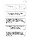
図3には、運転者によって選択されたトレーラ200に向かって牽引車両100に自律操縦させる、コントローラ160によって実行されるステップについてのフローチャート300が示されている。ブロック302において、運転者は、ユーザインタフェース130によってヒッチ支援システム170の実行を開始する。ディスプレイ140は、牽引車両100の後方ビューを含む、リアカメラ152から受信した画像151を表示する。運転者は、牽引車両100の後ろに位置付けられた1つ以上のトレーラ200、200a~cから、トレーラ200に関連付けられかつ選択されたトレーラ表現146aの周りで、トレーラバウンディングボックス144aを手動で入力するかまたは描画することができる。ブロック304では、ヒッチ支援システム170により、実ワールド座標においてまたはカメラ152に対して相対的に車両牽引ボール122の位置を特定する。別の複数の実施例では、ヒッチ支援システム170により、メモリハードウェア164から車両牽引ボール122の位置を取り出し可能である。ブロック306では、トレーラ追跡器172aにより、選択されたトレーラバウンディングボックス144aに基づいて、画像151内でのトレーラ表現146aの位置を識別し、牽引車両100が後方に移動する間にトレーラ200(すなわちトレーラ200の正面202)を追跡する。ブロック308では、運転者は、トレーラ表現についての自分の選択が完了したことをユーザインタフェース130によって指示するか、または運転者は、牽引車両100をバックギアに入れ、これによって牽引車両100に、トレーラバウンディングボックス144a内のトレーラ表現146aに関連付けられたトレーラ200に向かって、その自律操縦を開始させる。自律操縦の間、運動補正システム180により、トレーラ追跡器172aによって供給されるデータに基づき、車両100が、トレーラバウンディングボックス144aに向かって操縦するように維持する補正ステアリング角度が特定されてこれが実現される。いくつの実施例では、トレーラ追跡器172aにより、牽引車両100の前後方向軸Yと、トレーラバウンディングボックス144aの底辺の中心点であるバウンディングボックス中心145とが考慮される。トレーラ追跡器172aおよび運動補正システム180により、牽引車両100の前後方向軸Yと、トレーラ200を含むバウンディングボックス中心点145とが位置合わせされる。いくつかの実装形態では、図4に示したように、トレーラ追跡器172aにより、トレーラ200からあらかじめ定めた距離に位置付けられたバウンディングボックスヒットライン400が特定される。したがってブロック312では、牽引車両100が、トレーラ200に向かって後方向Rに自律操縦している間に、牽引車両100がバウンディングボックスヒットライン400に到達したか否かがトレーラ追跡器172aによってチェックされる。トレーラ追跡器172aにより、牽引車両100が、バウンディングボックスヒットライン400に到達したことが特定されると、トレーラ追跡器172aは、ブロック314に示したように、牽引車両100を停止するように運転者支援システム190および/または運転システム110に指示する。引き続いてブロック316において、ユーザインタフェース130が、ディスプレイ140によって運転者に求めるのは、図5Aおよび図5Bに示したような画像151により、トレーラカプラ212のカプラ表現502の周りのカプラバウンディングボックス144bを入力することである。いくつかの実施例では、ブロック316において、牽引車両100の位置がバウンディングボックスヒットライン400にあることにより、画像151によってトレーラ200およびカプラ212のさらに接近した画像が取り込まれる。付加的には運転者は、カプラ表現502の周りのより正確なカプラバウンディングボックス144bを提供するために、トレーラカプラ212の周りのバウンディングボックス144bを入力する前に画像151にズームインすることが可能である。 FIG. 3 shows a
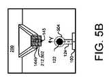
ブロック318では、カプラ追跡器172bにより、選択されたカプラバウンディングボックス144bに基づいて、画像151内のカプラ表現502の位置が識別される。ブロック320では、運転者は、カプラ表現502についての自分の選択が完了したことをユーザインタフェース130によって指示するか、または運転者は、牽引車両100をバックギアに入れ、これにより、ブロック322において、牽引車両100に、バウンディングボックス144b内のカプラ表現502に関連付けられたカプラ212に向かってその自律操縦を継続させる。自律操縦の間、運動補正システム180により、車両100が、選択されたカプラバウンディングボックス144bに関連付けられたカプラ212に向かって操縦するように維持する補正ステアリング角度が特定されてこれが実現される。カプラ追跡器172bおよび運動補正システム180により、牽引車両100の前後方向軸Yと、カプラ212を含むカプラバウンディングボックス144bの底辺のボックス中心点145とが位置合わせされる。いくつかの実施例では、コントローラ160により、さらに、影に対するロバストネスを向上させるために、より詳しく言えば、カプラ212が日光の下にありかつ操縦の間に影に入る場合に、カプラ212を含む画像151が処理される。機能を改善してさらに原画像に取り入れて戻すために、カプラバウンディングボックス144bの周りで、例えば、変換(例えば、ベイヤー変換、CLAHEまたはアフィン変換)を実行する。このとき、結果的に得られる画像は、カプラ212を追跡するためにカプラ追跡器172bによって使用される。いくつかの実装形態では、図5Bに示したように、カプラ追跡器172bにより、画像151内の車両牽引ボール122が識別され、車両牽引ボール122の周りに牽引ボールバウンディングサークル504が生成される。ブロック324では、カプラ追跡器172bにより、バウンディングボックス144bが、バウンディングサークル504に到達するかまたはこれと重なるか否かが特定される。カプラ追跡器172bにより、バウンディングボックス144bがバウンディングサークル504に到達するかまたはこれと重なることが特定されると、トレーラ追跡器172aは、ブロック326に示したように、牽引車両100を停止するように運転支援システム190および/または運転システム110に指示する。 At block 318,
いくつかの実装形態では、ヒッチ支援システム170により、牽引車両100を後方向Rに操縦する間に、追跡器172の、したがって運動補正システム180の精度を改善するために、追跡器172に加えて車両運動推定器174が実行される。車両運動推定器174は、ホイールエンコーダ154からホイールティックデータ155と、ステアリングホイール角度センサ156からステアリングホイール角度データ157とを受信して、車両位置、車両の向き、車速および車両角速度を特定する。追跡器172(すなわちトレーラ追跡器172aおよびカプラ追跡器172b)は、牽引車両100が後方向Rに自律操縦するのに伴って、トレーラ200またはトレーラカプラ212の追跡を改善するために、車両運動推定器174からのデータを使用可能である。いくつかの実施例において、追跡器出力データおよび車両運動推定器出力データは融合され、運動補正システム180は、融合されたこのデータに依拠して、トレーラ200またはカプラ212に向かう車両操縦を決定する。 In some implementations, the hitch assist system 170, while steering the
再び図2を参照すると、車両コントローラ160は、バウンディングボックス144、144a、144bに向かう自律操縦を車両100に維持させる補正ステアリング角度を特定してこれを実現する運動補正システム180を実行する。牽引車両100が、バウンディングボックス144に向かって自律操縦するのに伴い、運動補正システム180は、センサデータおよび追跡されたデータを連続して受信することに基づいて車両自律操縦を調整する。いくつかの実施例では、対象体検出システムにより、車両100とトレーラ200との間の1つ以上の対象体を識別し、1つ以上の対象体の位置に関連するデータを運動補正システム180に送信する。この場合、運動補正システム180により、1つ以上の対象体を回避するために車両自律操縦が調整される。いくつかの実施例では、運動補正システム180により、衝突の確率が特定され、衝突の確率が、あらかじめ定められた閾値を上回る場合、運動補正システム180により、車両自律運動操縦が調整され、これが運転支援システム190に送信される。 Referring again to FIG. 2,
運動補正システム180によって車両自律運動操縦が特定されると、車両コントローラ160により、運転支援システム190が実行される。運転支援システム190それ自体には自律動作192が含まれる。自律動作192は、車両自律動作操縦を受信し、コマンド/命令191を運転システム110に送信する1つ以上の動作192a~cを実行して、車両自律運動操縦に基づいて車両100に自律運転させ、これにより、バウンディングボックス144、144a、144bに向かって車両100を自律運転させる。 Once an autonomous vehicle maneuver has been identified by the motion correction system 180 , the
自律動作192a~cは、ブレーキング動作192a、加減速動作192b、ステアリング動作192cのような1つ以上の動作を含んでいてよいが、これらには限定されない。それぞれの動作192a~cは、後方への運転、特定の角度での方向転換、ブレーキング、加速、減速などのような行動を車両100に取らせる。車両コントローラ160は、運転システム110を制御することによって、より具体的には運転システム110に信号、コマンドまたは命令191を出すことによって、道路表面にわたって任意の方向に車両100を操縦可能である。 Autonomous actions 192a-c may include, but are not limited to, one or more actions such as braking action 192a, acceleration/deceleration action 192b, and steering action 192c. Each action 192a-c causes the
ブレーキング動作192aは、車両自律操縦に基づき、車両100を停止させるか、または車両100を減速するために実行可能である。ブレーキング動作192aは、牽引車両100を停止するか、または牽引車両100の速度を減じるために、運転システム110、例えばブレーキシステム(図示せず)に信号、コマンドまたは命令191を送信する。 Braking operation 192a may be performed to stop
加減速動作192bは、車両自律操縦に基づいて、加速または減速することにより、牽引車両100の速度を変更するために実行可能である。加減速動作192bは、減速のためにブレーキシステム114に、または加速のために加速システム116に信号、コマンドまたは命令191を送信する。 The acceleration/deceleration operation 192b can be performed to change the speed of the towing
ステアリング動作192cは、車両自律操縦に基づいて、牽引車両100の方向を変更するために実行可能である。したがってステアリング動作192cは、運転システム110に方向を変更させるステアリングの角度を示す信号、コマンドまたは命令191を加速システム116に送信する。 A steering operation 192c may be performed to change the direction of the
上述のようにコントローラ160により、ヒッチ支援システム170、運動補正システム180および運転支援システム190がリアルタイムに実行される。したがって上記のシステムにより、限定された運転者入力しか必要としない自動化された方法が提供される。
図6には、図1~図5Bに示したシステムを使用して、選択されたトレーラ200に向かって後方向Rに車両100(例えば牽引車両)を自律操縦させる方法600の動作の例示的な構成が示されている。方法600では、ブロック602において、牽引車両100の後部に位置付けられかつデータ処理ハードウェア162と通信するカメラ152から、1つ以上の画像をデータ処理ハードウェア162において受信する。方法600では、ブロック604において、1つ以上の画像151内のトレーラ表現146の第1ユーザ選択(例えばトレーラバウンディングボックス144、144a)をデータ処理ハードウェア162において受信する。方法600では、ブロック606において、トレーラ表現146の第1ユーザ選択144aに関連付けられたトレーラ200に向かって後方向Rに牽引車両100を自律操縦させる第1命令191を、データ処理ハードウェア162から、データ処理ハードウェア162と通信する運転システム110に送信する。方法600では、ブロック608において、1つ以上の画像151内のカプラ表現502の第2ユーザ選択(例えばカプラバウンディングボックス144、144b)をデータ処理ハードウェア162において受信する。カプラ表現502は、トレーラ200のトレーラカプラ212に関連付けられている。方法600では、ブロック610において、カプラ表現502の第2ユーザ選択144bに関連付けられたトレーラカプラ212に向かって後方向Rに牽引車両100を自律操縦させる第2命令191を、データ処理ハードウェア162から運転システム110に送信する。 FIG. 6 illustrates exemplary operations of a
いくつかの実装形態において、方法600では、トレーラ表現の第1ユーザ選択に関連付けられたトレーラに向かって後方向に牽引車両が自律操縦するのに伴って、1つ以上の画像内のトレーラバウンディングボックス144aを追跡する。方法600ではまた、カプラ表現502の第2ユーザ選択144bに関連付けられたトレーラカプラ212に向かって後方向Rに牽引車両100を自律操縦させるのに伴って、1つ以上の画像151内でカプラバウンディングボックス144bを追跡する。方法600ではまた、1つ以上のホイールエンコーダ154からホイールティックセンサデータ155を、またステアリングホイール角度センサ156からステアリングホイール角度データ157を受信してもよい。方法600では、ホイールティックセンサデータ155およびステアリングホイール角度データ157に基づいて、車両位置を特定し、トレーラおよびカプラに対して相対的な牽引車両位置に基づいて、第1命令および/または第2命令191をそれぞれ調整する。 In some implementations, the
いくつかの実装形態において、方法600では、牽引車両100の牽引ボール122の牽引ボール位置を特定する。後方向Rに牽引車両100が自律操縦する間に、方法600では、牽引ボールと、トレーラバウンディングボックス144aまたはカプラバウンディングボックス144bの中心との間の長手方向距離DLgおよび横方向距離DLtを特定する。ここで中心145は、トレーラバウンディングボックス144aまたはカプラバウンディングボックス144bの底部の中心である。いくつかの実施例では、第1および第2命令は、長手方向距離DLgおよび横方向距離DLtを減少させる。In some implementations,
ここで説明したシステムおよび技術のさまざまな実装形態は、デジタル電子回路、集積回路、特別に設計されたASIC(application specific integrated circuit)、コンピュータハードウェア、ファームウェア、ソフトウェアおよび/またはこれらの組み合わせで実現可能である。これらのさまざまな実装形態は、少なくとも1つのプログラマブルプロセッサを含むプログラマブルシステム上で実行可能および/またはインタープリト可能な1つ以上のコンピュータプログラムにおける実装形態を含むことができ、このプログラマブルプロセッサは、記憶システムおよび少なくとも1つの入力デバイスからデータおよび命令を受信し、また記憶システムおよび少なくとも1つの出力デバイスにデータおよび命令を送信するために接続される特殊用途または汎用のものであってよい。 Various implementations of the systems and techniques described herein can be implemented in digital electronic circuits, integrated circuits, specially designed application specific integrated circuits (ASICs), computer hardware, firmware, software and/or combinations thereof. is. These various implementations may include implementations in one or more computer programs executable and/or interpretable on a programmable system that includes at least one programmable processor, which is a storage system. and to receive data and instructions from and at least one input device, and to transmit data and instructions to a storage system and at least one output device.
(プログラム、ソフトウェア、ソフトウェアアプリケーションまたはコードとしても知られている)これらのコンピュータプログラムには、プログラマブルプロセッサ用の機械命令が含まれ、高水準手続き型および/またはオブジェクト指向プログラミング言語および/またはアセンブリ言語/機械語で実現可能である。ここで使用される「機械読み出し可能媒体」および「コンピュータ読み出し可能媒体」という用語は、機械読み出し可能信号として機械命令を受信する機械読み出し可能媒体を含む、プログラマブルプロセッサに機械命令および/またはデータを供給するために使用される任意のコンピュータプログラム製品、装置および/またはデバイス(例えば磁気ディスク、光ディスク、メモリ、PLD(Programmable Logic Device))のことである。「機械読み出し可能信号」という用語は、プログラマブルプロセッサに機械命令および/またはデータを供給するために使用される任意の信号のことである。 These computer programs (also known as programs, software, software applications or code) contain machine instructions for programmable processors and can be written in high-level procedural and/or object-oriented programming languages and/or assembly language/ It can be implemented in machine language. The terms "machine-readable medium" and "computer-readable medium" as used herein provide machine instructions and/or data to a programmable processor, including any machine-readable medium that receives machine instructions as machine-readable signals. any computer program product, apparatus and/or device (eg, magnetic disk, optical disk, memory, PLD (Programmable Logic Device)) used to The term "machine-readable signal" refers to any signal used to provide machine instructions and/or data to a programmable processor.
本明細書で説明した対象事項および機能的な動作の実装形態は、本明細書で開示した複数の構造およびこれらの構造の等価物、またはこれらの1つ以上の組み合わせを含め、デジタル電子回路、またはコンピュータソフトウェア、ファームウェアまたはハードウェアで実現可能である。さらに本明細書で説明した対象事項は、1つ以上のコンピュータプログラム製品、すなわち、データ処理装置による実行のために、またはその動作を制御するためにコンピュータ読み出し可能媒体に符号化されるコンピュータプログラム命令の1つ以上のモジュールとして実装可能である。コンピュータ読み出し可能媒体は、機械読み出し可能記憶装置、機械読み出し可能記憶基体、メモリデバイス、機械読み出し可能伝播信号に影響を及ぼす組成物、またはこれらの1つ以上の組み合わせであってよい。「データ処理装置」、「コンピューティングデバイス」および「コンピューティングプロセッサ」という用語には、例としてプログラマブルプロセッサ、コンピュータまたはマルチプロセッサまたはマルチコンピュータを含む、データを処理するすべての装置、デバイスおよび機械が包含される。装置は、ハードウェアに加えて、対象となるコンピュータプログラムに対する実行環境を作成するコード、例えばプロセッサファームウェア、プロトコルスタック、データベース管理システム、オペレーティングシステムまたはこれらの1つ以上の組み合わせを構成するコードを含んでいてよい。伝播信号は、人工的に生成される信号、例えば、適切な受信装置への送信用に情報を符号化するために生成される、機械で生成される電気信号、光信号または電磁信号である。 The subject matter and functional operational implementations described herein include the structures disclosed herein and equivalents of those structures, or combinations of one or more thereof, including digital electronic circuits, Or it can be implemented in computer software, firmware or hardware. Furthermore, the subject matter described herein may be one or more computer program products, i.e., computer program instructions encoded on a computer readable medium for execution by, or for controlling the operation of, a data processing apparatus. can be implemented as one or more modules of A computer-readable medium may be a machine-readable storage device, a machine-readable storage substrate, a memory device, a composition that affects a machine-readable propagated signal, or a combination of one or more of these. The terms "data processing apparatus", "computing device" and "computing processor" encompass all apparatus, devices and machines that process data including, by way of example, programmable processors, computers or multiprocessors or multicomputers. be done. In addition to hardware, the apparatus includes code that creates an execution environment for the subject computer program, such as processor firmware, protocol stacks, database management systems, operating systems, or code that constitutes a combination of one or more of these. you can stay A propagated signal is an artificially generated signal, for example, a machine-generated electrical, optical, or electromagnetic signal generated to encode information for transmission to a suitable receiving device.
同様に、動作は、図面において特定の順序で描画されているが、このことは、このような動作が、ここで示した特定の順序または順番に実行されるか、または所望の結果を達成するために、説明されたすべての動作が実行されることを要求していると理解すべきではない。特定の状況では、マルチタスキングおよび並列処理が有利になることがある。さらに、上述の複数の実施形態においてさまざまなシステムコンポーネントが分離されていることは、すべての実施形態においてこのように分離されることを要求していると理解すべきではなく、上述のプログラムコンポーネントおよびシステムは、一般に、単一のソフトウェア製品に一体で統合可能であるか、または複数のソフトウェア製品にパッケージング可能であると理解すべきである。 Similarly, although acts may be drawn in the figures in a particular order, it does not mean that such acts are performed in the specific order or order presented or to achieve the desired result. should not be construed as requiring that all of the operations described be performed. Multitasking and parallel processing can be advantageous in certain situations. Furthermore, the separation of various system components in the above-described embodiments should not be understood to require such separation in all embodiments, rather than the program components and It should be understood that the system can generally be integrated together into a single software product or packaged into multiple software products.
ここまで多くの実装形態を説明した。それにもかかわらず、本開示の精神および範囲を逸脱することなく、さまざまな変更を行い得ることを理解されたい。したがって別の実装形態も以下の特許請求の範囲内にある。 A number of implementations have been described thus far. Nevertheless, it should be understood that various modifications may be made without departing from the spirit and scope of the disclosure. Accordingly, other implementations are within the scope of the following claims.
Claims (12)
Translated fromJapanese前記牽引車両の後部に位置付けられかつデータ処理ハードウェアと通信するカメラから、1つ以上の画像を前記データ処理ハードウェアにおいて受信するステップと、
1つ以上の前記画像内のトレーラ表現の第1ユーザ選択を前記データ処理ハードウェアにおいて受信するステップと、
前記トレーラ表現の前記第1ユーザ選択に関連付けられた前記トレーラに向かって後方向に前記牽引車両を自律操縦させる第1命令を、前記データ処理ハードウェアから、前記データ処理ハードウェアと通信する運転システムに送信するステップと、
1つ以上の前記画像内の、前記トレーラのトレーラカプラに関連付けられたカプラ表現の第2ユーザ選択を前記データ処理ハードウェアにおいて受信するステップと、
前記カプラ表現の前記第2ユーザ選択に関連付けられた前記トレーラカプラに向かって前記後方向に前記牽引車両を自律操縦させる第2命令を、前記データ処理ハードウェアから前記運転システムに送信するステップと、
を含み、
前記方法は、
前記牽引車両の牽引ボールの牽引ボール位置を特定するステップと、
前記後方向に前記牽引車両が自律操縦する間に、前記牽引ボール位置と、トレーラバウンディングボックスまたはカプラバウンディングボックスの中心との間の長手方向距離および横方向距離を特定するステップと、
をさらに含み、
前記中心は、前記トレーラバウンディングボックスまたは前記カプラバウンディングボックスの底部の中心である、
方法。A method of autonomously steering a tow vehicle toward a trailer positioned behind the tow vehicle, the method comprising:
receiving at the data processing hardware one or more images from a camera positioned at the rear of the towing vehicle and in communication with the data processing hardware;
receiving at the data processing hardware a first user selection of trailer representations in one or more of the images;
A driving system communicating from the data processing hardware to the data processing hardware first instructions to autonomously steer the tow vehicle in a rearward direction toward the trailer associated with the first user selection of the trailer representation. sending to
receiving at the data processing hardware a second user selection of coupler representations associated with trailer couplers of the trailer in one or more of the images;
sending a second instruction from the data processing hardware to the driving system to autonomously steer the towing vehicle in the rearward direction toward the trailer coupler associated with the second user selection of the coupler representation;
including
The method includes:
identifying a tow ball location of a tow ball of the tow vehicle;
determining longitudinal and lateral distances between the tow ball position and the center of a trailer bounding box or coupler bounding box while the tow vehicle autonomously steers in the rearward direction;
further comprising
the center is the center of the bottom of the trailer bounding box or the coupler bounding box;
Method.
前記カプラ表現の前記第2ユーザ選択に関連付けられた前記トレーラカプラに向かって前記後方向に前記牽引車両が自律操縦するのに伴って、1つ以上の前記画像内で前記第2ユーザ選択を追跡するステップと、
をさらに含む、請求項1記載の方法。Tracking the firstuser selection in one or more of the images as the tow vehicle autonomously steers in the rearward direction toward the trailer associated with the first user selection of the trailer representation. a step;
Tracking the seconduser selection in one or more of the images as the tow vehicle autonomously steers in the rearward direction toward the trailer coupler associated with the second user selection of the coupler representation. and
2. The method of claim 1, further comprising:
前記ホイールティックセンサデータおよび前記ステアリングホイール角度データに基づいて牽引車両位置を特定するステップと、
前記トレーラおよび前記トレーラカプラに対して相対的な前記牽引車両位置に基づいて、前記第1命令および/または前記第2命令をそれぞれ調整するステップと、
をさらに含む、請求項4記載の方法。receiving wheel tick sensor data and steering wheel angle data from a sensor system in communication with the data processing hardware;
determining atow vehicle position based on the wheel tick sensor data and the steering wheel angle data;
adjusting the first command and/or the second command based on thetow vehicle position relative to the trailer and the trailer coupler, respectively;
5. The method of claim 4, further comprising:
通信を行うデータ処理ハードウェアと、
前記データ処理ハードウェアと通信するメモリハードウェアと、
を有し、
前記メモリハードウェアには、前記データ処理ハードウェア上で実行される場合に、前記データ処理ハードウェアに動作を実行させる命令が格納されており、前記動作は、
前記牽引車両の後部に位置付けられかつ前記データ処理ハードウェアと通信するカメラから、1つ以上の画像を受信し、
1つ以上の前記画像内のトレーラ表現の第1ユーザ選択を受信し、
前記トレーラ表現の前記第1ユーザ選択に関連付けられた前記トレーラに向かって後方向に前記牽引車両を自律操縦させる第1命令を運転システムに送信し、
1つ以上の前記画像内の、前記トレーラのトレーラカプラに関連付けられたカプラ表現の第2ユーザ選択を受信し、
前記カプラ表現の前記第2ユーザ選択に関連付けられた前記トレーラカプラに向かって前記後方向に前記牽引車両を自律操縦させる第2命令を、前記運転システムに送信する、
ことを含み、
前記動作は、
前記牽引車両の牽引ボールの牽引ボール位置を特定し、
前記後方向に前記牽引車両が自律操縦する間に、前記牽引ボール位置と、トレーラバウンディングボックスまたはカプラバウンディングボックスの中心との間の長手方向距離および横方向距離を特定すること
をさらに含み、前記中心は、前記トレーラバウンディングボックスまたは前記カプラバウンディングボックスの底部の中心である、
システム。A system for autonomously steering a tow vehicle toward a trailer positioned behind the tow vehicle, the system comprising:
data processing hardware for communication;
memory hardware in communication with the data processing hardware;
has
The memory hardware stores instructions that, when executed on the data processing hardware, cause the data processing hardware to perform an operation, the operation comprising:
receiving one or more images from a camera positioned at the rear of the towing vehicle and in communication with the data processing hardware;
receiving a first user selection of a trailer representation in one or more of said images;
sending a first command to a driving system to autonomously steer the towing vehicle in a rearward direction toward the trailer associated with the first user selection of the trailer representation;
receiving a second user selection of coupler representations associated with trailer couplers of the trailer in one or more of the images;
sending a second command to the driving system to autonomously steer the towing vehicle in the rearward direction toward the trailer coupler associated with the second user selection of the coupler representation;
including
The operation is
identifying a tow ball location for a tow ball of the tow vehicle;
Determining longitudinal and lateral distances between the tow ball position and the center of a trailer bounding box or coupler bounding box while the tow vehicle autonomously steers in the rearward direction.
wherein the center is the center of the bottom of the trailer bounding box or the coupler bounding box.
system.
前記トレーラ表現の前記第1ユーザ選択に関連付けられた前記トレーラに向かって前記後方向に前記牽引車両が自律操縦するのに伴って、1つ以上の前記画像内で前記第1ユーザ選択を追跡し、
前記カプラ表現の前記第2ユーザ選択に関連付けられた前記トレーラカプラに向かって前記後方向に前記牽引車両が自律操縦するのに伴って、1つ以上の前記画像内で前記第2ユーザ選択を追跡する、
ことを含む、請求項7記載のシステム。Said operation further comprises:
tracking the firstuser selection in one or more of the images as the tow vehicle autonomously steers in the rearward direction toward the trailer associated with the first user selection of the trailer representation; ,
Tracking the seconduser selection in one or more of the images as the tow vehicle autonomously steers in the rearward direction toward the trailer coupler associated with the second user selection of the coupler representation. do,
8. The system of claim7 , comprising:
前記データ処理ハードウェアと通信するセンサシステムからホイールティックセンサデータおよびステアリングホイール角度データを受信し、
前記ホイールティックセンサデータおよび前記ステアリングホイール角度データに基づいて牽引車両位置を特定し、
前記トレーラおよび前記トレーラカプラに対して相対的な前記牽引車両位置に基づいて、前記第1命令および/または前記第2命令をそれぞれ調整する、
ことを含む、請求項10記載のシステム。Said operation further comprises:
receiving wheel tick sensor data and steering wheel angle data from a sensor system in communication with the data processing hardware;
determining atow vehicle position based on the wheel tick sensor data and the steering wheel angle data;
adjusting the first command and/or the second command based on thetow vehicle position relative to the trailer and the trailer coupler, respectively;
11. The system of claim10 , comprising:
Applications Claiming Priority (5)
| Application Number | Priority Date | Filing Date | Title |
|---|---|---|---|
| US201862714419P | 2018-08-03 | 2018-08-03 | |
| US62/714,419 | 2018-08-03 | ||
| US16/530,933US11148667B2 (en) | 2018-08-03 | 2019-08-02 | Automated reversing by choice of target location |
| US16/530,933 | 2019-08-02 | ||
| PCT/US2019/045080WO2020028895A1 (en) | 2018-08-03 | 2019-08-05 | Automated reversing by choice of target location |
Publications (2)
| Publication Number | Publication Date |
|---|---|
| JP2021533027A JP2021533027A (en) | 2021-12-02 |
| JP7136997B2true JP7136997B2 (en) | 2022-09-13 |
Family
ID=69227306
Family Applications (1)
| Application Number | Title | Priority Date | Filing Date |
|---|---|---|---|
| JP2021505871AActiveJP7136997B2 (en) | 2018-08-03 | 2019-08-05 | Automatic retraction with target position selection |
Country Status (5)
| Country | Link |
|---|---|
| US (1) | US11148667B2 (en) |
| EP (1) | EP3829960B1 (en) |
| JP (1) | JP7136997B2 (en) |
| CN (1) | CN112752700B (en) |
| WO (1) | WO2020028895A1 (en) |
Families Citing this family (21)
| Publication number | Priority date | Publication date | Assignee | Title |
|---|---|---|---|---|
| US11518204B2 (en)* | 2018-05-01 | 2022-12-06 | Continental Autonomous Mobility US, LLC | Trailer detection and autonomous hitching |
| US10829152B2 (en)* | 2018-11-08 | 2020-11-10 | Ford Global Technologies, Llc | Automated hitching system with subject trailer selection from multiple identified trailers |
| US11030476B2 (en)* | 2018-11-29 | 2021-06-08 | Element Ai Inc. | System and method for detecting and tracking objects |
| US11491833B2 (en)* | 2019-01-29 | 2022-11-08 | Ford Global Technologies, Llc | System and methods for vehicle alignment control |
| US11180146B2 (en)* | 2019-05-14 | 2021-11-23 | Ford Global Technologies, Llc | Brake control technique to stop a vehicle for assisting automatic trailer hitching |
| US11904778B2 (en)* | 2019-05-14 | 2024-02-20 | Magna Electronics Inc. | Vehicular rear vision system with trailer connection verification |
| US11192552B2 (en)* | 2019-06-13 | 2021-12-07 | Ford Global Technologies, Llc | Vehicle motion control for trailer alignment |
| US11104300B2 (en)* | 2019-07-01 | 2021-08-31 | Nio Usa, Inc. | Radio frequency tag relay attack prevention and notification |
| US11299158B2 (en) | 2019-07-02 | 2022-04-12 | Ford Global Technologies, Llc | Unintended standstill response in an assisted hitching operation |
| US11427199B2 (en)* | 2019-08-22 | 2022-08-30 | Ford Global Technologies Llc | System for aligning a vehicle hitch location identifier with a trailer coupler |
| US11487290B2 (en)* | 2019-10-08 | 2022-11-01 | Toyota Motor North America, Inc. | Systems and methods for tracking an accessory by a wheelchair and coupling the wheelchair to the accessory |
| DE102020103597A1 (en)* | 2020-02-12 | 2021-08-12 | Saf-Holland Gmbh | Method and system for determining an orientation of a trailer with respect to a towing vehicle |
| IT202000012133A1 (en) | 2020-05-27 | 2021-11-27 | Nicola Carelli | NEW SYSTEM FOR THE PRODUCTION OF ELECTRICITY AND CRYPTOCURRENCIES BY ROLLING MOTION |
| EP4001058B1 (en)* | 2020-11-12 | 2025-07-09 | Volvo Truck Corporation | A system for guiding a vehicle towards a connecting vehicle which is to be connected to the vehicle |
| US11676300B2 (en)* | 2020-12-09 | 2023-06-13 | Continental Autonomous Mobility US, LLC | Method for real-time tow ball detection |
| US20220203786A1 (en)* | 2020-12-30 | 2022-06-30 | Continental Automotive Systems, Inc. | Method and assembly for positioning a vehicle relative to a trailer |
| CN113552888B (en)* | 2021-07-29 | 2022-07-19 | 中国第一汽车股份有限公司 | Driving track control method, device, equipment and medium applied to unmanned vehicle |
| CN113428155B (en)* | 2021-08-11 | 2022-08-19 | 浙江吉利控股集团有限公司 | Method and device for butting tractor and traction carriage and storage medium |
| CN113771561A (en)* | 2021-09-23 | 2021-12-10 | 广州小鹏汽车科技有限公司 | Vehicle towing method, electronic device, towing vehicle and storage medium |
| US11995877B2 (en)* | 2021-12-23 | 2024-05-28 | Continental Autonomous Mobility US, LLC | Visual tracking of target features |
| US20250303806A1 (en)* | 2024-03-29 | 2025-10-02 | Pebble Mobility, Inc. | Systems and methods for positioning one or more coupling sensors on an autonomous electric-powered trailer |
Citations (3)
| Publication number | Priority date | Publication date | Assignee | Title |
|---|---|---|---|---|
| US20160288601A1 (en) | 2015-04-01 | 2016-10-06 | Robert Bosch Gmbh | Trailer coupling assistance system with vehicle video camera |
| JP2016203972A (en) | 2015-04-14 | 2016-12-08 | コンチネンタル オートモーティブ システムズ インコーポレイテッドContinental Automotive Systems, Inc. | Automated hitching assist system |
| US20160378118A1 (en) | 2015-06-23 | 2016-12-29 | GM Global Technology Operations LLC | Smart trailer hitch control using hmi assisted visual servoing |
Family Cites Families (6)
| Publication number | Priority date | Publication date | Assignee | Title |
|---|---|---|---|---|
| US6292094B1 (en)* | 2001-01-16 | 2001-09-18 | General Motors Corporation | Vehicle-trailer backing-up control system with vehicle rear wheel steering |
| JP2002359839A (en)* | 2001-03-29 | 2002-12-13 | Matsushita Electric Ind Co Ltd | Rear view camera image display method and device |
| JP3945467B2 (en)* | 2003-10-02 | 2007-07-18 | 日産自動車株式会社 | Vehicle retraction support apparatus and method |
| US8138899B2 (en)* | 2009-07-01 | 2012-03-20 | Ford Global Technologies, Llc | Rear camera backup assistance with touchscreen display using two points of interest |
| US9914333B2 (en) | 2012-07-05 | 2018-03-13 | Uusi, Llc | Vehicle trailer connect system |
| US11148488B2 (en)* | 2018-06-26 | 2021-10-19 | Ford Global Technologies, Llc | System and method for positioning a vehicle with reduced variation |
- 2019
- 2019-08-02USUS16/530,933patent/US11148667B2/enactiveActive
- 2019-08-05EPEP19755479.3Apatent/EP3829960B1/enactiveActive
- 2019-08-05WOPCT/US2019/045080patent/WO2020028895A1/ennot_activeCeased
- 2019-08-05CNCN201980065021.2Apatent/CN112752700B/enactiveActive
- 2019-08-05JPJP2021505871Apatent/JP7136997B2/enactiveActive
Patent Citations (3)
| Publication number | Priority date | Publication date | Assignee | Title |
|---|---|---|---|---|
| US20160288601A1 (en) | 2015-04-01 | 2016-10-06 | Robert Bosch Gmbh | Trailer coupling assistance system with vehicle video camera |
| JP2016203972A (en) | 2015-04-14 | 2016-12-08 | コンチネンタル オートモーティブ システムズ インコーポレイテッドContinental Automotive Systems, Inc. | Automated hitching assist system |
| US20160378118A1 (en) | 2015-06-23 | 2016-12-29 | GM Global Technology Operations LLC | Smart trailer hitch control using hmi assisted visual servoing |
Also Published As
| Publication number | Publication date |
|---|---|
| CN112752700A (en) | 2021-05-04 |
| US11148667B2 (en) | 2021-10-19 |
| EP3829960B1 (en) | 2025-10-08 |
| WO2020028895A1 (en) | 2020-02-06 |
| JP2021533027A (en) | 2021-12-02 |
| CN112752700B (en) | 2024-05-17 |
| US20200039517A1 (en) | 2020-02-06 |
| EP3829960A1 (en) | 2021-06-09 |
Similar Documents
| Publication | Publication Date | Title |
|---|---|---|
| JP7136997B2 (en) | Automatic retraction with target position selection | |
| EP3787909B1 (en) | Coupler and tow-bar detection for automated trailer hitching via cloud points | |
| JP7124117B2 (en) | Trailer detection and autonomous hitching | |
| CN112424002B (en) | Visual Object Tracker | |
| JP7412412B2 (en) | Automatic reversing by following user-selected trajectory and estimating vehicle movement | |
| JP7520875B2 (en) | Autonomous steering and parking of vehicles-trailers | |
| CN112805207B (en) | User adjustable trajectory for automatic vehicle reversing | |
| EP4032066B1 (en) | Automatic trailer camera calibration | |
| US12405364B2 (en) | Fusion of short range radars and tailgate cameras for trailer angle estimation | |
| JP2023536468A (en) | A long-term visual trailer tracker for vehicle-trailer angle estimation | |
| JP7630602B2 (en) | Method and system for determining trailer angle and non-transitory computer readable medium - Patents.com | |
| WO2022087561A1 (en) | Trained trailer parking system and method |
Legal Events
| Date | Code | Title | Description |
|---|---|---|---|
| A621 | Written request for application examination | Free format text:JAPANESE INTERMEDIATE CODE: A621 Effective date:20210331 | |
| A977 | Report on retrieval | Free format text:JAPANESE INTERMEDIATE CODE: A971007 Effective date:20220325 | |
| A131 | Notification of reasons for refusal | Free format text:JAPANESE INTERMEDIATE CODE: A131 Effective date:20220404 | |
| A521 | Request for written amendment filed | Free format text:JAPANESE INTERMEDIATE CODE: A523 Effective date:20220701 | |
| TRDD | Decision of grant or rejection written | ||
| A01 | Written decision to grant a patent or to grant a registration (utility model) | Free format text:JAPANESE INTERMEDIATE CODE: A01 Effective date:20220803 | |
| A61 | First payment of annual fees (during grant procedure) | Free format text:JAPANESE INTERMEDIATE CODE: A61 Effective date:20220901 | |
| R150 | Certificate of patent or registration of utility model | Ref document number:7136997 Country of ref document:JP Free format text:JAPANESE INTERMEDIATE CODE: R150 | |
| R250 | Receipt of annual fees | Free format text:JAPANESE INTERMEDIATE CODE: R250 |