JP7134229B2 - Tissue grasping device and related method - Google Patents
Tissue grasping device and related methodDownload PDFInfo
- Publication number
- JP7134229B2 JP7134229B2JP2020521853AJP2020521853AJP7134229B2JP 7134229 B2JP7134229 B2JP 7134229B2JP 2020521853 AJP2020521853 AJP 2020521853AJP 2020521853 AJP2020521853 AJP 2020521853AJP 7134229 B2JP7134229 B2JP 7134229B2
- Authority
- JP
- Japan
- Prior art keywords
- anchor
- prosthetic
- leaf spring
- mitral valve
- delivery
- Prior art date
- Legal status (The legal status is an assumption and is not a legal conclusion. Google has not performed a legal analysis and makes no representation as to the accuracy of the status listed.)
- Active
Links
Images


Classifications
- A—HUMAN NECESSITIES
- A61—MEDICAL OR VETERINARY SCIENCE; HYGIENE
- A61F—FILTERS IMPLANTABLE INTO BLOOD VESSELS; PROSTHESES; DEVICES PROVIDING PATENCY TO, OR PREVENTING COLLAPSING OF, TUBULAR STRUCTURES OF THE BODY, e.g. STENTS; ORTHOPAEDIC, NURSING OR CONTRACEPTIVE DEVICES; FOMENTATION; TREATMENT OR PROTECTION OF EYES OR EARS; BANDAGES, DRESSINGS OR ABSORBENT PADS; FIRST-AID KITS
- A61F2/00—Filters implantable into blood vessels; Prostheses, i.e. artificial substitutes or replacements for parts of the body; Appliances for connecting them with the body; Devices providing patency to, or preventing collapsing of, tubular structures of the body, e.g. stents
- A61F2/02—Prostheses implantable into the body
- A61F2/24—Heart valves ; Vascular valves, e.g. venous valves; Heart implants, e.g. passive devices for improving the function of the native valve or the heart muscle; Transmyocardial revascularisation [TMR] devices; Valves implantable in the body
- A61F2/2442—Annuloplasty rings or inserts for correcting the valve shape; Implants for improving the function of a native heart valve
- A61F2/2463—Implants forming part of the valve leaflets
- A—HUMAN NECESSITIES
- A61—MEDICAL OR VETERINARY SCIENCE; HYGIENE
- A61B—DIAGNOSIS; SURGERY; IDENTIFICATION
- A61B17/00—Surgical instruments, devices or methods
- A61B17/12—Surgical instruments, devices or methods for ligaturing or otherwise compressing tubular parts of the body, e.g. blood vessels or umbilical cord
- A61B17/122—Clamps or clips, e.g. for the umbilical cord
- A—HUMAN NECESSITIES
- A61—MEDICAL OR VETERINARY SCIENCE; HYGIENE
- A61F—FILTERS IMPLANTABLE INTO BLOOD VESSELS; PROSTHESES; DEVICES PROVIDING PATENCY TO, OR PREVENTING COLLAPSING OF, TUBULAR STRUCTURES OF THE BODY, e.g. STENTS; ORTHOPAEDIC, NURSING OR CONTRACEPTIVE DEVICES; FOMENTATION; TREATMENT OR PROTECTION OF EYES OR EARS; BANDAGES, DRESSINGS OR ABSORBENT PADS; FIRST-AID KITS
- A61F2/00—Filters implantable into blood vessels; Prostheses, i.e. artificial substitutes or replacements for parts of the body; Appliances for connecting them with the body; Devices providing patency to, or preventing collapsing of, tubular structures of the body, e.g. stents
- A61F2/02—Prostheses implantable into the body
- A61F2/24—Heart valves ; Vascular valves, e.g. venous valves; Heart implants, e.g. passive devices for improving the function of the native valve or the heart muscle; Transmyocardial revascularisation [TMR] devices; Valves implantable in the body
- A61F2/2442—Annuloplasty rings or inserts for correcting the valve shape; Implants for improving the function of a native heart valve
- A61F2/246—Devices for obstructing a leak through a native valve in a closed condition
- A—HUMAN NECESSITIES
- A61—MEDICAL OR VETERINARY SCIENCE; HYGIENE
- A61B—DIAGNOSIS; SURGERY; IDENTIFICATION
- A61B17/00—Surgical instruments, devices or methods
- A61B17/12—Surgical instruments, devices or methods for ligaturing or otherwise compressing tubular parts of the body, e.g. blood vessels or umbilical cord
- A61B17/122—Clamps or clips, e.g. for the umbilical cord
- A61B17/1227—Spring clips
- A—HUMAN NECESSITIES
- A61—MEDICAL OR VETERINARY SCIENCE; HYGIENE
- A61B—DIAGNOSIS; SURGERY; IDENTIFICATION
- A61B17/00—Surgical instruments, devices or methods
- A61B17/00234—Surgical instruments, devices or methods for minimally invasive surgery
- A61B2017/00238—Type of minimally invasive operation
- A61B2017/00243—Type of minimally invasive operation cardiac
- A—HUMAN NECESSITIES
- A61—MEDICAL OR VETERINARY SCIENCE; HYGIENE
- A61B—DIAGNOSIS; SURGERY; IDENTIFICATION
- A61B17/00—Surgical instruments, devices or methods
- A61B2017/00535—Surgical instruments, devices or methods pneumatically or hydraulically operated
- A61B2017/00557—Surgical instruments, devices or methods pneumatically or hydraulically operated inflatable
- A—HUMAN NECESSITIES
- A61—MEDICAL OR VETERINARY SCIENCE; HYGIENE
- A61B—DIAGNOSIS; SURGERY; IDENTIFICATION
- A61B17/00—Surgical instruments, devices or methods
- A61B2017/00743—Type of operation; Specification of treatment sites
- A61B2017/00778—Operations on blood vessels
- A61B2017/00783—Valvuloplasty
- A—HUMAN NECESSITIES
- A61—MEDICAL OR VETERINARY SCIENCE; HYGIENE
- A61F—FILTERS IMPLANTABLE INTO BLOOD VESSELS; PROSTHESES; DEVICES PROVIDING PATENCY TO, OR PREVENTING COLLAPSING OF, TUBULAR STRUCTURES OF THE BODY, e.g. STENTS; ORTHOPAEDIC, NURSING OR CONTRACEPTIVE DEVICES; FOMENTATION; TREATMENT OR PROTECTION OF EYES OR EARS; BANDAGES, DRESSINGS OR ABSORBENT PADS; FIRST-AID KITS
- A61F2/00—Filters implantable into blood vessels; Prostheses, i.e. artificial substitutes or replacements for parts of the body; Appliances for connecting them with the body; Devices providing patency to, or preventing collapsing of, tubular structures of the body, e.g. stents
- A61F2/0077—Special surfaces of prostheses, e.g. for improving ingrowth
- A—HUMAN NECESSITIES
- A61—MEDICAL OR VETERINARY SCIENCE; HYGIENE
- A61F—FILTERS IMPLANTABLE INTO BLOOD VESSELS; PROSTHESES; DEVICES PROVIDING PATENCY TO, OR PREVENTING COLLAPSING OF, TUBULAR STRUCTURES OF THE BODY, e.g. STENTS; ORTHOPAEDIC, NURSING OR CONTRACEPTIVE DEVICES; FOMENTATION; TREATMENT OR PROTECTION OF EYES OR EARS; BANDAGES, DRESSINGS OR ABSORBENT PADS; FIRST-AID KITS
- A61F2/00—Filters implantable into blood vessels; Prostheses, i.e. artificial substitutes or replacements for parts of the body; Appliances for connecting them with the body; Devices providing patency to, or preventing collapsing of, tubular structures of the body, e.g. stents
- A61F2/02—Prostheses implantable into the body
- A61F2/24—Heart valves ; Vascular valves, e.g. venous valves; Heart implants, e.g. passive devices for improving the function of the native valve or the heart muscle; Transmyocardial revascularisation [TMR] devices; Valves implantable in the body
- A61F2/2442—Annuloplasty rings or inserts for correcting the valve shape; Implants for improving the function of a native heart valve
- A61F2/2466—Delivery devices therefor
- A—HUMAN NECESSITIES
- A61—MEDICAL OR VETERINARY SCIENCE; HYGIENE
- A61F—FILTERS IMPLANTABLE INTO BLOOD VESSELS; PROSTHESES; DEVICES PROVIDING PATENCY TO, OR PREVENTING COLLAPSING OF, TUBULAR STRUCTURES OF THE BODY, e.g. STENTS; ORTHOPAEDIC, NURSING OR CONTRACEPTIVE DEVICES; FOMENTATION; TREATMENT OR PROTECTION OF EYES OR EARS; BANDAGES, DRESSINGS OR ABSORBENT PADS; FIRST-AID KITS
- A61F2/00—Filters implantable into blood vessels; Prostheses, i.e. artificial substitutes or replacements for parts of the body; Appliances for connecting them with the body; Devices providing patency to, or preventing collapsing of, tubular structures of the body, e.g. stents
- A61F2/95—Instruments specially adapted for placement or removal of stents or stent-grafts
- A61F2002/9528—Instruments specially adapted for placement or removal of stents or stent-grafts for retrieval of stents
- A—HUMAN NECESSITIES
- A61—MEDICAL OR VETERINARY SCIENCE; HYGIENE
- A61F—FILTERS IMPLANTABLE INTO BLOOD VESSELS; PROSTHESES; DEVICES PROVIDING PATENCY TO, OR PREVENTING COLLAPSING OF, TUBULAR STRUCTURES OF THE BODY, e.g. STENTS; ORTHOPAEDIC, NURSING OR CONTRACEPTIVE DEVICES; FOMENTATION; TREATMENT OR PROTECTION OF EYES OR EARS; BANDAGES, DRESSINGS OR ABSORBENT PADS; FIRST-AID KITS
- A61F2210/00—Particular material properties of prostheses classified in groups A61F2/00 - A61F2/26 or A61F2/82 or A61F9/00 or A61F11/00 or subgroups thereof
- A61F2210/0014—Particular material properties of prostheses classified in groups A61F2/00 - A61F2/26 or A61F2/82 or A61F9/00 or A61F11/00 or subgroups thereof using shape memory or superelastic materials, e.g. nitinol
- A—HUMAN NECESSITIES
- A61—MEDICAL OR VETERINARY SCIENCE; HYGIENE
- A61F—FILTERS IMPLANTABLE INTO BLOOD VESSELS; PROSTHESES; DEVICES PROVIDING PATENCY TO, OR PREVENTING COLLAPSING OF, TUBULAR STRUCTURES OF THE BODY, e.g. STENTS; ORTHOPAEDIC, NURSING OR CONTRACEPTIVE DEVICES; FOMENTATION; TREATMENT OR PROTECTION OF EYES OR EARS; BANDAGES, DRESSINGS OR ABSORBENT PADS; FIRST-AID KITS
- A61F2220/00—Fixations or connections for prostheses classified in groups A61F2/00 - A61F2/26 or A61F2/82 or A61F9/00 or A61F11/00 or subgroups thereof
- A61F2220/0008—Fixation appliances for connecting prostheses to the body
- A—HUMAN NECESSITIES
- A61—MEDICAL OR VETERINARY SCIENCE; HYGIENE
- A61F—FILTERS IMPLANTABLE INTO BLOOD VESSELS; PROSTHESES; DEVICES PROVIDING PATENCY TO, OR PREVENTING COLLAPSING OF, TUBULAR STRUCTURES OF THE BODY, e.g. STENTS; ORTHOPAEDIC, NURSING OR CONTRACEPTIVE DEVICES; FOMENTATION; TREATMENT OR PROTECTION OF EYES OR EARS; BANDAGES, DRESSINGS OR ABSORBENT PADS; FIRST-AID KITS
- A61F2250/00—Special features of prostheses classified in groups A61F2/00 - A61F2/26 or A61F2/82 or A61F9/00 or A61F11/00 or subgroups thereof
- A61F2250/0003—Special features of prostheses classified in groups A61F2/00 - A61F2/26 or A61F2/82 or A61F9/00 or A61F11/00 or subgroups thereof having an inflatable pocket filled with fluid, e.g. liquid or gas
- A—HUMAN NECESSITIES
- A61—MEDICAL OR VETERINARY SCIENCE; HYGIENE
- A61F—FILTERS IMPLANTABLE INTO BLOOD VESSELS; PROSTHESES; DEVICES PROVIDING PATENCY TO, OR PREVENTING COLLAPSING OF, TUBULAR STRUCTURES OF THE BODY, e.g. STENTS; ORTHOPAEDIC, NURSING OR CONTRACEPTIVE DEVICES; FOMENTATION; TREATMENT OR PROTECTION OF EYES OR EARS; BANDAGES, DRESSINGS OR ABSORBENT PADS; FIRST-AID KITS
- A61F2250/00—Special features of prostheses classified in groups A61F2/00 - A61F2/26 or A61F2/82 or A61F9/00 or A61F11/00 or subgroups thereof
- A61F2250/0014—Special features of prostheses classified in groups A61F2/00 - A61F2/26 or A61F2/82 or A61F9/00 or A61F11/00 or subgroups thereof having different values of a given property or geometrical feature, e.g. mechanical property or material property, at different locations within the same prosthesis
- A61F2250/0051—Special features of prostheses classified in groups A61F2/00 - A61F2/26 or A61F2/82 or A61F9/00 or A61F11/00 or subgroups thereof having different values of a given property or geometrical feature, e.g. mechanical property or material property, at different locations within the same prosthesis differing in tissue ingrowth capacity, e.g. made from both ingrowth-promoting and ingrowth-preventing parts
Landscapes
- Health & Medical Sciences (AREA)
- Cardiology (AREA)
- Life Sciences & Earth Sciences (AREA)
- General Health & Medical Sciences (AREA)
- Public Health (AREA)
- Veterinary Medicine (AREA)
- Engineering & Computer Science (AREA)
- Biomedical Technology (AREA)
- Heart & Thoracic Surgery (AREA)
- Vascular Medicine (AREA)
- Animal Behavior & Ethology (AREA)
- Oral & Maxillofacial Surgery (AREA)
- Transplantation (AREA)
- Surgery (AREA)
- Molecular Biology (AREA)
- Medical Informatics (AREA)
- Nuclear Medicine, Radiotherapy & Molecular Imaging (AREA)
- Reproductive Health (AREA)
- Prostheses (AREA)
Description
Translated fromJapanese(関連出願の相互参照)
本願は、2017年7月6日に出願された、仮特許出願第62/529,373号(弁理士整理番号第50389-705.101号)、2017年7月6日に出願された、第62/529,384号(弁理士整理番号第50389-706.101号)、2017年7月6日に出願された、第62/529,389号(弁理士整理番号第50389-707.101号)、2017年7月6日に出願された、第62/529,392号(弁理士整理番号第50389-708.101号)、2017年7月6日に出願された、第62/529,380号(弁理士整理番号第52206-705.101号)の利益を主張する。(Cross reference to related applications)
This application is based on Provisional Patent Application No. 62/529,373 (Attorney Docket No. 50389-705.101) filed July 6, 2017; 62/529,384 (Patent Attorney Docket No. 50389-706.101), No. 62/529,389 (Patent Attorney Docket No. 50389-707.101) filed on July 6, 2017 ), No. 62/529,392 filed July 6, 2017 (Patent Attorney Docket No. 50389-708.101), No. 62/529, filed July 6, 2017, 380 (Patent Attorney Docket No. 52206-705.101).
本願は、概して、心臓弁を修復するための医療デバイスおよび方法に関する。より具体的には、本発明は、低侵襲性および他の手技を通した僧帽弁および三尖心臓弁、静脈弁、および他の組織構造の修復のための方法およびデバイスに関する。 This application relates generally to medical devices and methods for repairing heart valves. More specifically, the present invention relates to methods and devices for the repair of mitral and tricuspid heart valves, venous valves, and other tissue structures through minimally invasive and other procedures.
自然心臓弁(すなわち、大動脈弁、肺動脈弁、三尖弁、および僧帽弁)は、心血管系を通した血液の適正な供給の順流を確実にする際に重要な機能を果たす。これらの心臓弁は、先天性奇形、炎症プロセス、感染性症状、または疾患によってあまり効果的ではないものにされ得る。弁へのそのような損傷は、深刻な心血管系障害または死亡をもたらし得る。長年にわたって、そのような障害に対する最終的な処置は、心臓切開外科手術の間の弁の外科手術修復または置換であった。しかしながら、そのような外科手術は、高度に侵襲性であり、多くの合併症を起こしやすい。したがって、欠陥のある心臓弁を伴う高齢および虚弱な患者は、多くの場合、処置を受けなかった。より最近では、経血管技法が、心臓切開外科手術よりもはるかに侵襲性ではない様式で補綴デバイスを導入および埋込するために開発された。そのような経血管技法は、それらの高い成功率に起因して需要が高まっている。 The native heart valves (ie, the aortic, pulmonary, tricuspid, and mitral valves) perform an important function in ensuring the proper forward flow of blood supply through the cardiovascular system. These heart valves can be rendered less effective by congenital malformations, inflammatory processes, infectious conditions, or disease. Such damage to valves can result in serious cardiovascular injury or death. For many years, the definitive treatment for such disorders was surgical repair or replacement of the valve during open heart surgery. However, such surgery is highly invasive and prone to many complications. Therefore, elderly and frail patients with defective heart valves often did not receive treatment. More recently, transvascular techniques have been developed to introduce and implant prosthetic devices in a much less invasive manner than open heart surgery. Such transvascular techniques are in increasing demand due to their high success rate.
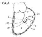
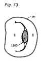
健康な心臓は、下側頂点に向かってテーパ状になる略円錐形状を有する。心臓は、4つに仕切られ、左心房と、右心房と、左心室と、右心室とを含む。心臓の左および右側は、概して、中隔と称される壁によって分離される。ヒト心臓の自然僧帽弁は、左心房を左心室に接続する。僧帽弁は、他の自然心臓弁と非常に異なる解剖学的構造を有する。僧帽弁は、僧帽弁オリフィスを囲繞する自然弁組織の環状部分である弁輪部分と、弁輪から左心室の中に下方に延在する先端の対または尖とを含む。僧帽弁輪は、D形、長円形、または別様に長軸および短軸を有する非真円断面形状を形成することができる。前尖は、後尖よりも大きく、それらがともに閉鎖されるとき、尖の当接する遊離縁の間に略「C」形境界を形成することができる。 A healthy heart has a generally conical shape that tapers to the lower apex. The heart is divided into four compartments, including the left atrium, right atrium, left ventricle, and right ventricle. The left and right sides of the heart are generally separated by a wall called the septum. The natural mitral valve of the human heart connects the left atrium to the left ventricle. The mitral valve has a very different anatomy than other native heart valves. The mitral valve includes an annulus portion, which is an annular portion of native valve tissue that surrounds the mitral valve orifice, and apical pairs or cusps that extend downward from the annulus into the left ventricle. The mitral annulus can form a D-shaped, oval, or otherwise non-circular cross-sectional shape having major and minor axes. The anterior leaflet is larger than the posterior leaflet and can form a generally "C" shaped boundary between the abutting free edges of the leaflets when they are closed together.
適切に動作しているとき、前尖および後尖は、血液が左心房から左心室にのみ流動することを可能にするための一方向弁としてともに機能する。左心房は、肺静脈から酸素化された血液を受容する。左心房の筋肉が収縮し、左心室が拡張すると、左心房内に収集された酸素化血液は、左心室に流入する。左心房の筋肉が弛緩し、左心室の筋肉が収縮すると、左心室内の血圧の増加は、2つの尖をともに押勢し、それによって、血液が左心房に逆流し得ず、代わりに、大動脈弁を通して左心室から排出されるように、一方向僧帽弁を閉鎖する。2つの尖が、圧力下で脱出し、僧帽弁輪を通して左心房に向かって折り返すことを防止するために、腱索と呼ばれる複数の線維索が、尖を左心室内の乳頭筋につなぐ。 When working properly, the anterior and posterior leaflets function together as a one-way valve to allow blood to flow only from the left atrium to the left ventricle. The left atrium receives oxygenated blood from the pulmonary veins. As the left atrial muscle contracts and the left ventricle dilates, oxygenated blood collected in the left atrium flows into the left ventricle. When the left atrium muscles relax and the left ventricular muscles contract, the increased blood pressure within the left ventricle forces the two cusps together so that blood cannot flow back into the left atrium, instead The one-way mitral valve is closed so that the left ventricle drains through the aortic valve. To prevent the two cusps from protruding under pressure and folding back through the mitral annulus toward the left atrium, multiple cords of fibers called chordae tendineae connect the cusps to the papillary muscles in the left ventricle.
僧帽弁逆流は、心臓収縮の収縮期の間に自然僧帽弁が適切に閉鎖できず、血液が左心室から左心房に流入するときに起こる。僧帽弁逆流は、心臓弁膜症の最も一般的な形態である。僧帽弁逆流は、尖脱出、機能不全の乳頭筋、および/または左心室の拡張からもたらされる僧帽弁輪の延伸等の異なる原因を有する。尖の中心部分における僧帽弁逆流は、中心ジェット僧帽弁逆流と称され得、尖の1つの交連(すなわち、尖が接する場所)により近傍の僧帽弁逆流は、偏心ジェット僧帽弁逆流と称され得る。僧帽弁逆流を処置するためのいくつかの従来技法は、自然僧帽弁尖の一部を相互に直接縫付することを含む。僧帽弁逆流のための最も一般的な処置は、弁置換または尖および弁輪再造形を含む弁修復に依拠し、後者は、概して、弁輪形成術と称される。他の従来技法は、自然僧帽弁尖の間に埋込されるスペーサの使用を含む。これらの従来技法にもかかわらず、僧帽弁逆流を処置するための改良されたデバイスおよび方法の継続的必要性がある。 Mitral regurgitation occurs when the native mitral valve fails to close properly during systole and blood flows from the left ventricle into the left atrium. Mitral regurgitation is the most common form of valvular heart disease. Mitral regurgitation has different causes, such as cusp prolapse, dysfunctional papillary muscles, and/or stretching of the mitral annulus resulting from dilatation of the left ventricle. Mitral regurgitation in the central portion of the leaflet may be referred to as central jet mitral regurgitation, and mitral regurgitation proximal to one of the leaflet's commissures (i.e., where the leaflets meet) is eccentric jet mitral regurgitation. can be called Some conventional techniques for treating mitral regurgitation involve sewing portions of the natural mitral valve leaflets directly together. The most common treatment for mitral regurgitation relies on valve replacement or valve repair, including leaflet and annulus remodeling, the latter commonly referred to as annuloplasty. Other conventional techniques involve the use of spacers that are implanted between the natural mitral valve leaflets. Despite these conventional techniques, there is a continuing need for improved devices and methods for treating mitral regurgitation.
本発明は、逆流を防止または低減させるために自然心臓弁をシールするために、インプラントおよび補綴デバイス等の装置およびそのような装置を加工し、埋込し、使用するための方法を提供する。
(スペーサ)The present invention provides devices such as implants and prosthetic devices and methods for fabricating, implanting and using such devices to seal native heart valves to prevent or reduce backflow.
(Spacer)
1.非圧縮性本体。いくつかの実施形態では、心臓弁逆流を処置するための補綴デバイスは、第1の端部、第2の端部、および第1の端部から第2の端部まで延在する外面を有する、半径方向に非圧縮性および/または非拡張可能な本体と、接続部分および尖捕捉部分を有するアンカとを備え、接続部分は、本体が半径方向拡張状態にあるとき、尖捕捉部分が本体の外面に対して付勢されるように本体に結合され、補綴デバイスは、アンカの尖捕捉部分と本体の外面との間の自然心臓弁の尖を捕捉するように構成され、本体は、第1の端部から第2の端部まで延在する方向において、および第2の端部から第1の端部まで延在する方向において、血液が本体を通して流動することを防止するように構成される。 1. Incompressible body. In some embodiments, a prosthetic device for treating heart valve regurgitation has a first end, a second end, and an outer surface extending from the first end to the second end. , a radially incompressible and/or non-expandable body and an anchor having a connecting portion and a leaflet capturing portion, wherein the connecting portion is such that when the body is in a radially expanded state, the leaflet capturing portion is attached to the body. The prosthetic device is coupled to the body so as to be biased against the outer surface, the prosthetic device configured to capture the cusps of the native heart valve between the cusp capture portion of the anchor and the outer surface of the body, the body including a first configured to prevent blood from flowing through the body in a direction extending from the end of the body to the second end and in a direction extending from the second end to the first end .
2.非圧縮性剛性本体。いくつかの実施形態では、心臓弁逆流を処置するための補綴デバイスは、第1の端部、第2の端部、および第1の端部から第2の端部まで延在する外面を有する、半径方向に非圧縮性および剛性の本体と、接続部分および尖捕捉部分を有するアンカとを備え、接続部分は、尖捕捉部分が本体の外面に対して付勢されるように本体に結合され、補綴デバイスは、アンカの尖捕捉部分と本体の外面との間の自然心臓弁の尖を捕捉するように構成され、本体は、第1の端部から第2の端部まで延在する方向において、および第2の端部から第1の端部まで延在する方向において、血液が本体を通して流動することを防止するように構成される。 2. Incompressible rigid body. In some embodiments, a prosthetic device for treating heart valve regurgitation has a first end, a second end, and an outer surface extending from the first end to the second end. , a radially incompressible and rigid body, and an anchor having a connecting portion and a leaflet capturing portion, the connecting portion coupled to the body such that the leaflet capturing portion is biased against the outer surface of the body. , the prosthetic device configured to capture the cusps of the native heart valve between the cusp-capturing portion of the anchor and the outer surface of the body, the body extending in a direction extending from the first end to the second end; and in a direction extending from the second end to the first end to prevent blood from flowing through the body.
3.非圧縮性可撓性本体。いくつかの実施形態では、心臓弁逆流を処置するための補綴デバイスは、第1の端部、第2の端部、および第1の端部から第2の端部まで延在する外面を有する、半径方向に非圧縮性および可撓性の本体と、接続部分および尖捕捉部分を有するアンカとを備え、接続部分は、尖捕捉部分が本体の外面に対して付勢されるように本体に結合され、補綴デバイスは、アンカの尖捕捉部分と本体の外面との間の自然心臓弁の尖を捕捉するように構成され、本体は、第1の端部から第2の端部まで延在する方向において、および第2の端部から第1の端部まで延在する方向において、血液が本体を通して流動することを防止するように構成される。 3. An incompressible flexible body. In some embodiments, a prosthetic device for treating heart valve regurgitation has a first end, a second end, and an outer surface extending from the first end to the second end. , a radially incompressible and flexible body and an anchor having a connecting portion and a leaflet capturing portion, the connecting portion being attached to the body such that the leaflet capturing portion is biased against the outer surface of the body. Coupled, the prosthetic device is configured to capture the cusps of the native heart valve between the cusp-capturing portion of the anchor and the outer surface of the body, the body extending from the first end to the second end. and in a direction extending from the second end to the first end to prevent blood from flowing through the body.
4.アンカレス非圧縮性本体。いくつかの実施形態では、心臓弁逆流を処置するための補綴デバイスは、第1の端部、第2の端部、および第1の端部から第2の端部まで延在する外面を有し、支持部分を有する、半径方向に非圧縮性および/または非拡張可能な本体を備え、支持部分は、ある程度の摺動移動が存在し得るように尖が本体の外面に対して位置付けられるように本体に結合されるが、しかしながら、全体的に、本体の位置は、第1の端部から第2の端部まで延在する方向において、および第2の端部から第1の端部まで延在する方向において、血液が本体を通して流動することを防止するように構成される。 4. Anchorage incompressible body. In some embodiments, a prosthetic device for treating heart valve regurgitation has a first end, a second end, and an outer surface extending from the first end to the second end. and a radially incompressible and/or non-expandable body having a support portion such that the cusps are positioned against the outer surface of the body such that there may be some degree of sliding movement. However, overall, the position of the body is in a direction extending from the first end to the second end and from the second end to the first end. It is configured to prevent blood from flowing through the body in the direction of extension.
5.アンカレス非圧縮性剛性本体。いくつかの実施形態では、心臓弁逆流を処置するための補綴デバイスは、第1の端部、第2の端部、および第1の端部から第2の端部まで延在する外面を有し、支持部分を有する、半径方向に非圧縮性および剛性の本体を備え、支持部分は、ある程度の摺動移動が存在し得るように尖が本体の外面に対して位置付けられるように本体に結合されるが、しかしながら、全体的に、本体の位置は、第1の端部から第2の端部まで延在する方向において、および第2の端部から第1の端部まで延在する方向において、血液が本体を通して流動することを防止するように構成される。 5. Anchorage incompressible rigid body. In some embodiments, a prosthetic device for treating heart valve regurgitation has a first end, a second end, and an outer surface extending from the first end to the second end. and a radially incompressible and rigid body having a support portion, the support portion coupled to the body such that the cusps are positioned against the outer surface of the body such that there may be some degree of sliding movement. However, generally the position of the body is in the direction extending from the first end to the second end and in the direction extending from the second end to the first end. is configured to prevent blood from flowing through the body.
6.アンカレス非圧縮性可撓性本体。いくつかの実施形態では、心臓弁逆流を処置するための補綴デバイスは、第1の端部、第2の端部、および第1の端部から第2の端部まで延在する外面を有し、支持部分を有する、半径方向に非圧縮性および可撓性の本体を備え、支持部分は、ある程度の摺動移動が存在し得るように尖が本体の外面に対して位置付けられるように本体に結合されるが、しかしながら、全体的に、本体の位置は、第1の端部から第2の端部まで延在する方向において、および第2の端部から第1の端部まで延在する方向において、血液が本体を通して流動することを防止するように構成される。 6. Anchorage incompressible flexible body. In some embodiments, a prosthetic device for treating heart valve regurgitation has a first end, a second end, and an outer surface extending from the first end to the second end. and a radially incompressible and flexible body having a support portion such that the cusps are positioned against the outer surface of the body such that there may be some degree of sliding movement. However, generally the position of the body is in a direction extending from the first end to the second end and from the second end to the first end. and configured to prevent blood from flowing through the body in a direction to.
7.アンカレス自由浮遊式圧縮可能および拡張可能本体。いくつかの実施形態では、心臓弁逆流を処置するための補綴デバイスは、第1の端部、第2の端部、および第1の端部から第2の端部まで延在する外面を有する、アンカレスかつ半径方向に圧縮可能および半径方向に拡張可能な本体を備え、外面は、半径方向拡張状態にあるとき、尖と接触し、本体は、第1の端部から第2の端部まで延在する方向において、および第2の端部から第1の端部まで延在する方向において、血液が本体を通して流動することを防止するように構成され、閉じ込められた空間内で自由に浮遊するように構成される。 7. Anchorage free-floating compressible and expandable body. In some embodiments, a prosthetic device for treating heart valve regurgitation has a first end, a second end, and an outer surface extending from the first end to the second end. , an anchorless, radially compressible and radially expandable body, the outer surface contacting the cusps when in the radially expanded state, the body extending from the first end to the second end; configured to prevent blood from flowing through the body in the direction of extension and in the direction extending from the second end to the first end and freely float within the confined space; configured as
8.アンカレス回収可能自由浮遊式圧縮可能および拡張可能本体。いくつかの実施形態では、心臓弁逆流を処置するための補綴デバイスは、第1の端部、第2の端部、および第1の端部から第2の端部まで延在する外面を有する、アンカレスかつ半径方向に圧縮可能および半径方向に拡張可能な本体を備え、外面は、半径方向拡張状態にあるとき、尖と接触し、本体は、第1の端部から第2の端部まで延在する方向において、および第2の端部から第1の端部まで延在する方向において、血液が本体を通して流動することを防止するように構成され、閉じ込められた空間内で自然弁に対して自由に浮遊するように構成され、第1の端部または第2の端部のいずれかから、および/または両方の端部から回収可能である。 8. Anchorless retractable free-floating compressible and expandable body. In some embodiments, a prosthetic device for treating heart valve regurgitation has a first end, a second end, and an outer surface extending from the first end to the second end. , an anchorless, radially compressible and radially expandable body, the outer surface contacting the cusps when in the radially expanded state, the body extending from the first end to the second end; configured to prevent blood from flowing through the body in a direction of extension and in a direction extending from the second end to the first end, against the native valve within the confined space; configured to be free-floating in the air and retrievable from either the first end or the second end and/or from both ends.
9.アンカレス回収可能自由浮遊式非圧縮性および拡張可能本体。いくつかの実施形態では、心臓弁逆流を処置するための補綴デバイスは、第1の端部、第2の端部、および第1の端部から第2の端部まで延在する外面を有する、アンカレスかつ半径方向に非圧縮性および半径方向に非拡張可能な本体を備え、外面は、半径方向拡張状態にあるとき、尖と接触し、本体は、第1の端部から第2の端部まで延在する方向において、および第2の端部から第1の端部まで延在する方向において、血液が本体を通して流動することを防止するように構成され、閉じ込められた空間内で自然弁に対して自由に浮遊するように構成され、第1の端部または第2の端部または両方の端部のいずれかから回収可能である。 9. Anchorless retractable free-floating incompressible and expandable body. In some embodiments, a prosthetic device for treating heart valve regurgitation has a first end, a second end, and an outer surface extending from the first end to the second end. , an anchorless and radially incompressible and radially non-expandable body, the outer surface contacting the cusps when in the radially expanded state, the body extending from the first end to the second end; a native valve within the confined space configured to prevent blood from flowing through the body in a direction extending to the portion and in a direction extending from the second end to the first end; and is retrievable from either the first end or the second end or both ends.
10.支持構造を伴うアンカレス回収可能自由浮遊式圧縮可能および拡張可能本体。いくつかの実施形態では、心臓弁逆流を処置するための補綴デバイスは、第1の端部、第2の端部、および第1の端部から第2の端部まで延在する外面を有し、心房または心室または両方の中に延在する支持構造を有する、アンカレスかつ半径方向に圧縮可能および半径方向に拡張可能な本体を備え、外面は、半径方向拡張状態にあるとき、尖と接触し、本体は、第1の端部から第2の端部まで延在する方向において、および第2の端部から第1の端部まで延在する方向において、血液が本体を通して流動することを防止するように構成され、支持構造によって画定されるような閉じ込められた空間内で自然弁に対して自由に浮遊するように構成される。 10. Anchorage retractable free-floating compressible and expandable body with support structure. In some embodiments, a prosthetic device for treating heart valve regurgitation has a first end, a second end, and an outer surface extending from the first end to the second end. and an anchorless, radially compressible and radially expandable body having a support structure extending into the atrium or the ventricle or both, the outer surface contacting the cusps when in the radially expanded state. and the body permits blood to flow through the body in a direction extending from the first end to the second end and in a direction extending from the second end to the first end. configured to prevent and to float freely relative to the native valve within a confined space as defined by the support structure.
11.弁および周囲の流動。いくつかの実施形態では、本体は、圧縮状態に非半径方向に圧縮可能であり、尖受容間隙が、本体とアンカの尖捕捉部分との間に存在し、本体は、拡張状態に伸縮自在に自己拡張可能である。いくつかの実施形態では、アンカは、第1のクリップ部分と、第2のクリップ部分とを備え、本デバイスは、第1および第2のクリップ部分の間の尖を捕捉するように構成される。いくつかの実施形態では、本体は、ニチノールから形成され、拡張状態に非半径方向に自己拡張可能である。いくつかの実施形態では、本体は、金属フレームと、フレーム上に搭載される血液不浸透性織物とを備える。いくつかの実施形態では、本体は、血液が、拡張期の間に、心房から心室に、人工弁を通してと、本体と捕捉されていない尖との間で本体の周囲でとの両方で流動することを可能にするように構成され、捕捉されていない尖が本体の周囲で閉鎖することを可能にし、収縮期の間に僧帽弁逆流を防止するように構成される。 11. valves and surrounding fluids. In some embodiments, the body is non-radially compressible to the compressed state, the leaflet-receiving gap exists between the body and the leaflet-capturing portion of the anchor, and the body is telescoping to the expanded state. Self extensible. In some embodiments, the anchor comprises a first clip portion and a second clip portion, and the device is configured to capture a cusp between the first and second clip portions. . In some embodiments, the body is formed from nitinol and is non-radially self-expandable to the expanded state. In some embodiments, the body comprises a metal frame and a blood impermeable fabric mounted on the frame. In some embodiments, the body allows blood to flow during diastole both from the atria to the ventricles, through the prosthetic valve, and around the body between the body and the uncaptured cusps. and is configured to allow uncaptured leaflets to close around the body to prevent mitral regurgitation during systole.
12.アンカ。いくつかの実施形態では、本体の外面は、それに対してアンカが付勢される第1の側と、第1の側に対向する第2の側とを備え、アンカの接続部分は、本体の第2の側上で本体に結合される。いくつかの実施形態では、アンカは、接続場所において本体の第2の側に結合される伸長部材を備え、伸長部材は、接続場所から本体の第1の端部を横断して延在する心室部分を備える。いくつかの実施形態では、心室部分は、第1および第2の心室部分を備え、第1の心室部分は、第2の心室部分に略平行である。 12. anchor. In some embodiments, the exterior surface of the body comprises a first side against which the anchor is biased and a second side opposite the first side, and the connecting portion of the anchor comprises Coupled to the body on the second side. In some embodiments, the anchor comprises an elongate member coupled to the second side of the body at the connection location, the elongate member extending from the connection location across the first end of the body. prepare the part. In some embodiments, the ventricular portion comprises first and second ventricular portions, the first ventricular portion being substantially parallel to the second ventricular portion.
13.心房安定化、形状。いくつかの実施形態では、アンカは、本体の第1の端部に結合され、本デバイスはさらに、本体の第2の端部から延在する心房安定化部材を備える。いくつかの実施形態では、本体は、捕捉された尖の運動とともに自然心臓弁内で移動するように構成される。いくつかの実施形態では、本体の心房端部部分は、本体の心房端部部分に向かって移動する直径が縮小するテーパ状肩部を備える。いくつかの実施形態では、本体は、三日月形断面形状を備える。いくつかの実施形態では、本体は、ドッグボーン形状を備える。いくつかの実施形態では、心房または心室区分は、ループを形成する、または本体の移動を限定するような形状に構成される。いくつかの実施形態では、本体は、平坦にされた長円形形状を備える。いくつかの実施形態では、アンカは、第1および第2のアンカを備え、本デバイスは、両方の自然僧帽弁尖に固着されるように構成される。 13. Atrial stabilization, shape. In some embodiments, the anchor is coupled to the first end of the body and the device further comprises an atrial stabilizing member extending from the second end of the body. In some embodiments, the body is configured to move within the native heart valve with movement of the captured leaflet. In some embodiments, the atrial end portion of the body comprises a tapered shoulder of decreasing diameter moving toward the atrial end portion of the body. In some embodiments, the body comprises a crescent cross-sectional shape. In some embodiments, the body comprises a dogbone shape. In some embodiments, the atrial or ventricular compartment is configured in a shape to form a loop or to limit movement of the body. In some embodiments, the body comprises a flattened oval shape. In some embodiments, the anchor comprises first and second anchors and the device is configured to be anchored to both native mitral valve leaflets.
いくつかの実施形態では、心臓弁逆流を処置するための補綴デバイスは、接続部分と、遊離端部分とを有する主要本体部分を備え、接続部分は、本デバイスが自然僧帽弁オリフィス内に埋込されるように、2つの自然僧帽弁尖のうちの第1のものに結合されるように構成され、本デバイスが自然僧帽弁オリフィス内に埋込されると、遊離端部分は、収縮期の間に2つの自然僧帽弁尖のうちの第2のものに向かって側方に移動し、それによって、収縮期の間にオリフィスをシールし、僧帽弁逆流を低減させることに役立ち、遊離端部分は、拡張期の間に第2の自然僧帽弁尖から離れるように側方に移動し、拡張期の間に血液が左心房から左心室に流動することを可能にする。 In some embodiments, a prosthetic device for treating heart valve regurgitation comprises a main body portion having a connecting portion and a free end portion, wherein the connecting portion allows the device to be implanted within the native mitral valve orifice. configured to be coupled to a first of the two native mitral valve leaflets such that when the device is implanted within the native mitral valve orifice, the free end portion: To move laterally towards the second of the two native mitral valve leaflets during systole, thereby sealing the orifice and reducing mitral regurgitation during systole. Serving, the free end portion moves laterally away from the second native mitral valve leaflet during diastole, allowing blood to flow from the left atrium to the left ventricle during diastole. .
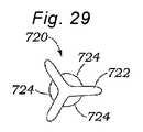
いくつかの実施形態では、主要本体の接続部分は、遊離端部分よりも厚い。いくつかの実施形態では、主要本体部分はさらに、第1の自然僧帽弁尖に隣接する左心房内の自然僧帽弁輪に接触する心房部分を備える。いくつかの実施形態では、本デバイスはさらに、第1の自然僧帽弁尖の下側端部の周囲をクリップ留めする心室アンカを備え、それによって、本デバイスを第1の自然僧帽弁尖に固着させる。いくつかの実施形態では、アンカは、広い上側端部部分および比較的に狭い縮径部部分を伴うパドル形状を備え、縮径部部分は、上側端部部分を主要本体に結合する。いくつかの実施形態では、アンカまたは本体のいずれかは、本デバイスを安定化させるために、外傷性および/または非外傷性返しを有する。いくつかの実施形態では、本体は、膨張可能バルーンから作製される。 In some embodiments, the connecting portion of the main body is thicker than the free end portion. In some embodiments, the main body portion further comprises an atrial portion that contacts the native mitral annulus in the left atrium adjacent the first native mitral valve leaflet. In some embodiments, the device further comprises a ventricular anchor that clips around the lower end of the first native mitral valve leaflet, thereby attaching the device to the first native mitral valve leaflet. stick to. In some embodiments, the anchor comprises a paddle shape with a wide upper end portion and a relatively narrow reduced diameter portion, the reduced diameter portion coupling the upper end portion to the main body. In some embodiments, either the anchor or the body have traumatic and/or atraumatic barbs to stabilize the device. In some embodiments, the body is made from an inflatable balloon.
14.板ばね。いくつかの好ましい実施形態では、本発明のデバイス、システム、および方法は、処置部位における組織の固定のために適合される。例示的組織固定用途は、心臓弁修復、中隔欠損修復、血管結紮および咬持、裂傷修復、および創傷閉鎖を含むが、本発明は、多種多様な組織接近および修復手技における使用を見出し得る。特に好ましい実施形態では、本発明のデバイス、システム、および方法は、逆流のための治療として、心臓弁、特に、僧帽弁の修復のために適合される。本発明は、逆流を低減させるために、「切端」または「ボウタイ」技法を使用して2つ以上の弁尖が接合されることを可能にするが、従来のアプローチのように胸部および心臓壁を通した観血術を要求しない。加えて、尖の位置は、石灰化、脱出、または動揺等の疾患のタイプおよび程度に応じて、罹患した僧帽弁において変動し得る。これらのタイプの疾患は、一方の尖が他方よりも可動性(例えば、捕捉することがより困難)であり、したがって、他方の尖と同一の把持において対称的に把持することがより困難であることをもたらし得る。本発明の特徴は、固定デバイスが、予測不可能な標的組織幾何学形状の課題を満たすように適合され、かついったんこれが捕捉されると、組織に対してよりロバストな把持を提供することを可能にする。本発明は、インプラントが埋込後に回収されることを可能にする特徴を備える。加えて、本発明は、随意に、公知かつ典型的な可視化技法を組み込み、デバイス留置手技が全身麻酔の使用を伴わずに実施されることを可能にする。 14. Leaf spring. In some preferred embodiments, the devices, systems and methods of the present invention are adapted for fixation of tissue at a treatment site. Exemplary tissue fixation applications include heart valve repair, septal defect repair, vessel ligation and occlusion, laceration repair, and wound closure, but the present invention may find use in a wide variety of tissue access and repair procedures. In particularly preferred embodiments, the devices, systems and methods of the present invention are adapted for repair of heart valves, particularly mitral valves, as a treatment for regurgitation. The present invention allows two or more leaflets to be brought together using the "incisal" or "bowtie" technique to reduce regurgitation, but the thoracic and heart wall as in conventional approaches. Does not require invasive surgery through the Additionally, leaflet position may vary in a diseased mitral valve depending on the type and degree of disease such as calcification, prolapse, or perturbation. In these types of disorders, one cusp is more mobile (e.g., more difficult to grasp) than the other and thus more difficult to grasp symmetrically in the same grasp as the other cusp. can bring about A feature of the present invention is that the fixation device can be adapted to meet the challenges of unpredictable target tissue geometries and, once captured, provide a more robust grip on the tissue. to The present invention includes features that allow the implant to be retrieved after implantation. Additionally, the present invention optionally incorporates known and typical visualization techniques to allow device placement procedures to be performed without the use of general anesthesia.
本発明のデバイス、システム、および方法は、介入システムを形成するために、個別に、または種々の組み合わせにおいて使用され得る種々のデバイスを中心とする。好ましい実施形態では、介入システムは、マルチカテーテル誘導システム、送達カテーテル、および介入デバイスを含む。これらの構成要素はそれぞれ、本明細書に議論されるであろう。 The devices, systems, and methods of the present invention focus on various devices that can be used individually or in various combinations to form an interventional system. In preferred embodiments, the interventional system includes a multi-catheter guidance system, a delivery catheter, and an interventional device. Each of these components will be discussed herein.
例示的実施形態では、本発明は、外側アーム(または固定要素)の対を有する固定デバイスを提供し、各外側アームは、遊離端と、組織に係合するための係合面とを有し、外側アームは、組織を捕捉するための第1の位置と組織を固定するための第2の位置との間で移動可能である。好ましくは、係合面は、第1の位置において離間され、第2の位置においてともにより近接し、概して、相互に向かって面する。固定デバイスは、好ましくは、伸長シャフトと、近位端と、遠位端とを有する送達カテーテルによって、患者の身体内の標的場所に送達され、送達カテーテルは、血管穿刺または切開または外科手術貫通等の遠隔アクセス点から標的場所に位置付けられるように構成される。好ましい実施形態では、標的場所は、心臓内の弁である。 In an exemplary embodiment, the invention provides a fixation device having a pair of outer arms (or fixation elements), each outer arm having a free end and an engagement surface for engaging tissue. , the outer arm is movable between a first position for capturing tissue and a second position for securing tissue. Preferably, the engagement surfaces are spaced apart in the first position and closer together in the second position and generally face toward each other. The fixation device is preferably delivered to a target location within the patient's body by a delivery catheter having an elongated shaft, a proximal end and a distal end, the delivery catheter being used for vascular puncture or incision or surgical penetration or the like. is configured to be positioned at a target location from a remote access point of the. In a preferred embodiment, the target location is a valve within the heart.
本発明の特定の利点は、平行または垂直関係において僧帽弁の尖(またはこれが使用される任意の他の組織)を接合し、およびその解剖学的外形に沿って尖を把持するその能力である。言い換えると、接合深さを殆どまたは全く伴わなくても、尖は、それらの近位上流面が、相互に平行に配置され、概して、接合点における弁を通した流動の方向と整合されるように、捕捉され、ともに引き寄せられ、固定され得る。固定デバイスのいくつかの実施形態では、十分に剛性の外側アーム、高度に摩擦的かつ圧縮性の内側アーム、および受動的閉鎖機構の使用は、最適な接合構成を達成するために、尖を垂直に保ちながら(血流と整合される)、尖が離間関係において把持され、次いで、接合関係においてともに引き寄せられることを可能にする。 A particular advantage of the present invention is its ability to coapt the mitral valve leaflets (or any other tissue in which it is used) in a parallel or perpendicular relationship and to grasp the leaflets along their anatomical contours. be. In other words, with little or no coaptation depth, the cusps are arranged such that their proximal upstream faces are arranged parallel to each other and generally aligned with the direction of flow through the valve at the coaptation point. can be captured, drawn together, and secured. In some embodiments of the fixation device, the use of a sufficiently rigid outer arm, a highly frictional and compressible inner arm, and a passive closure mechanism keep the cusps perpendicular to achieve the optimal coaptation configuration. (aligned with blood flow), allowing the cusps to be grasped in a spaced apart relationship and then drawn together in a coaptational relationship.
本発明の特定の利点は、尖の解剖学的輪郭と並んで把持しながら、尖形状の近接する解剖学的関係において僧帽弁の尖(またはこれが使用される任意の他の組織)を接合するその能力である。言い換えると、尖は、それらの自然解剖学的形状が留保されるように、捕捉され、ともに引き寄せられ、固定され得る。固定デバイスのいくつかの実施形態では、十分に可撓性の外側アーム、高度に摩擦的かつ圧縮性の内側アーム、および受動的閉鎖機構の使用は、最適な接合構成を達成するために、尖を垂直に保ちながら(血流と整合される)、尖が離間関係において把持され、次いで、接合関係においてともに引き寄せられることを可能にする。 A particular advantage of the present invention is that it joins the mitral valve cusps (or any other tissue in which it is used) in cusp-shaped proximal anatomical relationship while grasping alongside the anatomical contours of the cusps. It is its ability to In other words, the cusps can be captured, drawn together, and fixed such that their natural anatomical shape is retained. In some embodiments of the fixation device, the use of a fully flexible outer arm, a highly frictional and compressible inner arm, and a passive closure mechanism are used to achieve an optimal coaptation configuration. Keeping the apex vertical (aligned with blood flow), allow the cusps to be grasped in a spaced apart relationship and then drawn together in a coaptational relationship.
固定デバイスは、好ましくは、本デバイスの外形を最小限にするように構成される送達位置における外側アームとともに送達される。心房側から僧帽弁に接近するとき、固定デバイスのいくつかの実施形態は、本デバイスが、心室側から尖を把持することが可能であるように、送達デバイスシャフトの縦方向軸に対して約90°を下回る、好ましくは、約20°を下回る角度を形成する略近位方向に向く外側アームの遊離端とともに送達されることを可能にする。本位置では、係合面は、概して、相互に向かって面しており、相互に対して約180°を下回る、好ましくは、約40°を下回る角度において配置される。心室アプローチに関して、送達位置では、外側アームの遊離端は、略遠位方向に向いており、心室側から尖を把持することが可能であるように、送達デバイスシャフトの縦方向軸に対して約90°を下回る、好ましくは、約20°を下回る角度を形成する。本位置では、係合面は、概して、相互に向かって面しており、通常、相互に対して約180°を下回る、好ましくは、約90°を下回る角度において配置される。代替として、いくつかの心室アプローチでは、送達位置において略近位方向に向く固定要素の遊離端および相互から離れるように面する係合面を有することが、好ましくあり得る。 The fixation device is preferably delivered with the outer arm in the delivery position configured to minimize the profile of the device. When approaching the mitral valve from the atrial side, some embodiments of the fixation device are positioned relative to the longitudinal axis of the delivery device shaft so that the device is able to grasp the leaflet from the ventricular side. It allows delivery with the free end of the outer arm facing in a generally proximal direction forming an angle of less than about 90°, preferably less than about 20°. In this position, the engagement surfaces generally face each other and are arranged at an angle of less than about 180°, preferably less than about 40°, relative to each other. For the ventricular approach, in the delivery position, the free end of the outer arm faces generally distally and is about 1.5 mm to the longitudinal axis of the delivery device shaft so as to be able to grasp the cusp from the ventricular side. It forms an angle of less than 90°, preferably less than about 20°. In this position, the engagement surfaces generally face each other and are typically arranged at an angle of less than about 180°, preferably less than about 90°, relative to each other. Alternatively, in some ventricular approaches, it may be preferable to have the free ends of the fixation elements facing generally proximally in the delivery position and the engagement surfaces facing away from each other.
本発明のデバイスおよびシステムの可逆性および除去可能性を提供するために、尖は、縫合糸またはワイヤおよび/またはカテーテルを使用して、十分に可撓性のアームから持ち上げられる。僧帽弁修復用途では、これは、腱索、弁尖、およびデバイスが絡合した状態になり得る他の組織の存在に起因して、特に重要である。(反転位置における)僧帽弁の心房側からのアプローチに関して、遊離端は、カテーテルシャフトに対して略遠位方向に向いており、係合面は、概して、相互から離れるように面し、通常、相互に対して約180°を上回る、好ましくは、270°を上回る角度において配置されるであろう。模倣された反転位置における弁への心室アプローチに関して、遊離端は、カテーテルシャフトに対して遠位方向に向いており、係合面は、概して、相互に向かって面し、通常、相互に対して約180°を下回る、好ましくは、90°を下回る角度において配置されているであろう。これには、アームを反転させ、係脱させる意図がある。 To provide reversibility and removability of the devices and systems of the present invention, the cusps are lifted from sufficiently flexible arms using sutures or wires and/or catheters. In mitral valve repair applications, this is particularly important due to the presence of chordae, leaflets, and other tissues that can become entangled with the device. For an atrial approach to the mitral valve (in the everted position), the free end faces generally distally with respect to the catheter shaft, and the engagement surfaces generally face away from each other, usually , to each other at an angle of more than about 180°, preferably more than 270°. For a ventricular approach to the valve in a simulated inverted position, the free ends face distally with respect to the catheter shaft and the engagement surfaces generally face toward each other, usually toward each other. It will be arranged at an angle of less than about 180°, preferably less than 90°. This is intended to flip and disengage the arm.
開放位置において、外側アームの係合面は、好ましくは、その中で弁尖または他の標的組織を捕捉する面積を最大限にするように、相互に対して最大180°の角度を形成する。外側アームは、好ましくは、係合面が相互に係合する、または相互に対して0°と同程度に小さい角度を形成する閉鎖位置まで可撓性である。遠位アームは、種々の厚さ、幾何学形状、および間隔の組織の固定を可能にするために、近位アームに対向する圧縮力を付与しながら、可撓性であり、種々の位置のうちのいずれかに恒久的に残されるように構成される。 In the open position, the engagement surfaces of the outer arms preferably form an angle of up to 180° with respect to each other to maximize the area for capturing leaflets or other target tissue therein. The outer arms are preferably flexible to a closed position in which the engagement surfaces engage each other or form an angle with each other as small as 0°. The distal arm is flexible and can be positioned in various locations while imparting an opposing compressive force to the proximal arm to allow fixation of tissue of various thicknesses, geometries, and spacings. configured to remain permanently in one of the
本発明の特定の利点は、外側および内側アームの両方が十分に超弾性かつ可撓性であり、a)尖の解剖学的形状およびb)尖に対する生理学的力と共形化するようにわずかな移動を可能にしながら、組織に対して永続的かつ緩やかな反力を付与することである。 A particular advantage of the present invention is that both the lateral and medial arms are sufficiently superelastic and flexible, and have a slight flex to conform to a) the anatomical shape of the cusps and b) the physiological forces on the cusps. It is to give a permanent and gentle reaction force to the tissue while allowing smooth movement.
本発明の別の特定の利点は、摩擦要素(返し)がアーム本体の長軸に沿って内側に設置され、連続的かつ中実の側面によって閉じ込められることである。MitraClip(R)デバイスとは異なり、返しは、側に沿って暴露されない。これは、腱索、弁尖、およびデバイスが絡合した状態になり得る他の組織の絡合のリスクを有意に低減させるため、有利である。さらに、本特徴は、縫合糸またはワイヤまたは潜在的に固定デバイスと接触し得る他のそのような送達カテーテル要素の絡合のリスクを低減させる。 Another particular advantage of the present invention is that the friction elements (barbs) are located internally along the long axis of the arm body and are confined by continuous and solid sides. Unlike the MitraClip(R) device, the barbs are not exposed along the sides. This is advantageous as it significantly reduces the risk of entanglement of chordae, leaflets, and other tissues that can become entangled with the device. In addition, this feature reduces the risk of entanglement of sutures or wires or other such delivery catheter elements that may potentially contact the fixation device.
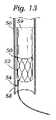
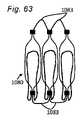
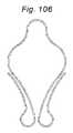
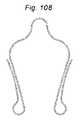
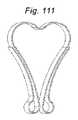
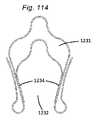
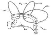
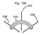
本発明の一側面は、血管に隣接する組織を再成形するために血管内に展開されるように適合される、組織成形デバイスを提供する。例示的実施形態では、本デバイスは、心房および心室側から尖に係合するための板ばね様並置特徴を備える。2つのそのような板ばね特徴は、僧帽弁の後尖および前尖のそれぞれを把持するために、基部において接続されてもよい。いくつかの実施形態では、上記の板ばねは、シート金属および/またはワイヤおよび/またはストリップおよび/または任意の他の好適な材料形態から作製されることができる。いくつかの実施形態では、板ばねは、捕捉された組織/尖を把持および/または拘束するために、アンカおよび/または返しを有することができる。 One aspect of the invention provides a tissue shaping device adapted to be deployed within a blood vessel to reshape tissue adjacent to the blood vessel. In an exemplary embodiment, the device comprises leaf spring-like apposition features for engaging the cusps from the atrial and ventricular sides. Two such leaf spring features may be connected at the base to grasp the posterior and anterior leaflets of the mitral valve, respectively. In some embodiments, the leaf springs described above can be made from sheet metal and/or wire and/or strip and/or any other suitable material form. In some embodiments, the leaf spring can have anchors and/or barbs to grasp and/or constrain the captured tissue/leaf.
いくつかの実施形態では、板ばねは、逆流をより良好に軽減するために、尖を拘束することに加えて、弁輪を緊締するように構成される。 In some embodiments, the leaf spring is configured to tighten the annulus in addition to constraining the leaflets to better mitigate regurgitation.
いくつかの実施形態では、対向する板ばねは、切断パターンの有無を問わず、ワイヤおよび/またはシート金属および/またはストリップおよび/または中実および/または中空形態の組み合わせから形成されることができる。 In some embodiments, the opposing leaf springs can be formed from a combination of wire and/or sheet metal and/or strip and/or solid and/or hollow forms with or without cut patterns. .
いくつかの実施形態では、板ばねは、それらが送達システム内で圧縮構成にあり、拡張構成において展開され得るように、拡張可能および/または圧縮可能であり得る。 In some embodiments, the leaf springs can be expandable and/or compressible such that they can be in a compressed configuration and deployed in an expanded configuration within the delivery system.
いくつかの実施形態では、カテーテルシャフトは、板ばねの特徴を操作し、尖を捕捉するために使用されてもよい。 In some embodiments, the catheter shaft may be used to manipulate leaf spring features and capture cusps.
いくつかの実施形態では、カテーテルは、板ばねを操作し、両方の尖を同時に捕捉するか、または尖を連続的に捕捉するかのいずれかのために、縫合糸またはワイヤまたは介入カテーテル技術において一般的に使用される任意の他の一般的な技法を使用してもよい。 In some embodiments, the catheter manipulates the leaf spring to either capture both cusps simultaneously or to capture the cusps sequentially or sutures or wires or in interventional catheter techniques. Any other commonly used technique may be used.
いくつかの実施形態では、1つのみの並置する板ばねが、対向する板ばねの対の代わりに使用されてもよい。これは、一方の尖(前尖または後尖)のみを捕捉する一方、他方の尖は、自由である。 In some embodiments, only one side-by-side leaf spring may be used in place of a pair of opposing leaf springs. It captures only one leaflet (anterior or posterior) while the other leaflet is free.
いくつかの実施形態では、前僧帽弁尖および後僧帽弁尖のうちの捕捉されていないものは、補綴シールデバイスが自然僧帽弁に埋込されているとき、シールデバイスに固着されない。 In some embodiments, the non-captured ones of the anterior and posterior mitral valve leaflets are not anchored to the sealing device when the prosthetic sealing device is implanted in the native mitral valve.
いくつかの実施形態では、左心室を介して自然僧帽弁領域に送達デバイスを前進させるステップは、左心室の頂点における切開部を通して左心室の中に送達デバイスを挿入するステップを含む。 In some embodiments, advancing the delivery device through the left ventricle into the native mitral valve region comprises inserting the delivery device into the left ventricle through an incision at the apex of the left ventricle.
いくつかの実施形態では、左心室から自然僧帽弁領域に送達システムを前進させるステップは、左心室の頂点における切開部を通して左心室の中に送達デバイスを挿入するステップを含む。 In some embodiments, advancing the delivery system from the left ventricle to the native mitral valve region comprises inserting the delivery device into the left ventricle through an incision at the apex of the left ventricle.
いくつかの実施形態では、送達システムが心臓の自然僧帽弁領域に前進されるとき、アンカは、補綴シールデバイスの本体の側に沿って遠位に延在する送達カテーテル内で略直線化位置に保持される。 In some embodiments, the anchor is in a generally straightened position within a delivery catheter extending distally along a side of the body of the prosthetic sealing device when the delivery system is advanced into the native mitral region of the heart. is held to
いくつかの実施形態では、心臓の自然僧帽弁に補綴シールデバイスを埋込する方法は、送達システムを心臓の左心房から心臓の自然僧帽弁領域に前進させるステップであって、送達システムは、補綴シールデバイスを格納する、ステップと、補綴シールデバイスのアンカが送達システム内に閉じ込められないように送達システムの外側シースを近位に後退させるステップと、自然僧帽弁尖が補綴シールデバイスのアンカと送達システムとの間に位置付けられるように心臓の左心房に向かって送達システムを後退させるステップと、補綴シールデバイスの本体が送達システム内に閉じ込められないように送達システムの内側シースを近位に後退させるステップであって、本体は、収縮期および拡張期の間に本体を通した血液の流動を防止するように構成される、ステップと、心臓の自然僧帽弁領域から送達システムを除去するステップとを含む。 In some embodiments, a method of implanting a prosthetic sealing device in a native mitral valve of a heart comprises advancing a delivery system from the left atrium of the heart to a native mitral valve region of the heart, wherein the delivery system comprises: , retracting the prosthetic sealing device; proximally retracting the outer sheath of the delivery system so that the anchor of the prosthetic sealing device is not trapped within the delivery system; retracting the delivery system toward the left atrium of the heart so that it is positioned between the anchor and the delivery system; and proximally moving the inner sheath of the delivery system so that the body of the prosthetic sealing device is not trapped within the delivery system. wherein the body is configured to prevent blood flow through the body during systole and diastole; and removing the delivery system from the natural mitral valve region of the heart. and the step of
いくつかの実施形態では、左心房から自然僧帽弁領域に送達システムを前進させるステップは、左心房と右心房との間の中隔の一部における切開部を通して送達システムを前進させるステップを含む。いくつかの実施形態では、送達システムが心臓の自然僧帽弁領域に前進されるとき、本デバイスは、補綴シールデバイスの本体から近位に延在する送達カテーテル内の略直線化位置に保持される。 In some embodiments, advancing the delivery system from the left atrium to the native mitral valve region comprises advancing the delivery system through an incision in a portion of the septum between the left and right atria. . In some embodiments, the device is held in a generally straightened position within a delivery catheter extending proximally from the body of the prosthetic sealing device as the delivery system is advanced to the native mitral region of the heart. be.
15.スペーサ板ばね。他の側面では、本発明は、自然心臓弁をシールし、それを通した逆流を防止または低減させることに役立てるための補綴デバイスおよび関連方法、およびそのような補綴デバイスを埋込するためのデバイスおよび関連方法を提供する。 15. Spacer leaf spring. In other aspects, the invention provides prosthetic devices and related methods to help seal a native heart valve and prevent or reduce reflux therethrough, and devices for implanting such prosthetic devices. and related methods.
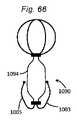
本発明の一側面は、血管に隣接する組織を再成形するために血管内に展開されるように適合される組織成形デバイスを提供する。例示的実施形態では、本デバイスは、心房および心室側から尖に係合するために、板ばねと、スペーサ様特徴とを備える。2つのそのような板ばね特徴は、僧帽弁の後尖および前尖のそれぞれを把持するために、基部および/または頂点において接続されてもよい。さらに、本発明は、逆流を軽減するために、スペーサと組み合わせてアルフィエリ切端弁修復を模倣する。 One aspect of the present invention provides a tissue shaping device adapted to be deployed within a blood vessel to reshape tissue adjacent the blood vessel. In an exemplary embodiment, the device includes leaf springs and spacer-like features to engage the cusps from the atrial and ventricular sides. Two such leaf spring features may be connected at the base and/or apex to grasp the posterior and anterior leaflets of the mitral valve, respectively. Additionally, the present invention mimics an Alfieri incisal valve repair in combination with a spacer to mitigate backflow.
いくつかの実施形態では、上記の板ばねは、シート金属および/またはワイヤから作製されることができる。いくつかの実施形態では、板ばねは、弾性および/または超弾性金属またはポリマーおよび/またはセラミックから作製されることができる。 In some embodiments, the leaf springs can be made from sheet metal and/or wire. In some embodiments, the leaf springs can be made from elastic and/or superelastic metals or polymers and/or ceramics.
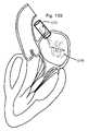
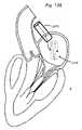
いくつかの実施形態では、補綴デバイスは、自然僧帽弁オリフィス内に埋込され、2つの自然僧帽弁尖のうちの第1のものに、または第1の自然僧帽弁尖に隣接する自然僧帽弁輪に結合される、または自由に浮遊するように構成される、板ばねを備え、埋込されると、本デバイスは、2つの接合する尖の間の空間を充填するように構成され、したがって、第1の自然僧帽弁尖または第1の自然僧帽弁尖に隣接する僧帽弁輪に結合されない組み立てられたデバイスの遊離部分は、2つの自然僧帽弁尖のうちの第2のものに向かって側方に移動し、それに対してシールし、僧帽弁逆流を低減させ、拡張期の間、第1の自然僧帽弁尖または第1の自然僧帽弁尖に隣接する自然僧帽弁輪に結合されない本デバイスの部分は、第2の自然僧帽弁尖から離れるように側方に移動し、血液が左心房から左心室に流動することを可能にする。 In some embodiments, the prosthetic device is implanted within the native mitral valve orifice and adjacent to the first of the two native mitral valve leaflets or the first native mitral valve leaflet. Comprising a leaf spring that is either coupled to the native mitral annulus or configured to float freely, when implanted the device fills the space between the two coapting leaflets. The free portion of the assembled device that is configured and thus not bonded to the first native mitral valve leaflet or the mitral annulus adjacent to the first native mitral valve leaflet is one of the two native mitral valve leaflets. moves laterally toward and seals against the second of the mitral valves to reduce mitral regurgitation and during diastole the first native mitral valve leaflet or the first native mitral valve leaflet The portion of the device that is not bound to the native mitral annulus adjacent to the mitral valve moves laterally away from the second native mitral valve leaflet, allowing blood to flow from the left atrium to the left ventricle. .
いくつかの実施形態では、組み立てられた区画化シートは、逆流を低減させるように、自然弁との直接接触を介してか、または心房または心室壁を使用するかのいずれかで、該自然僧帽弁尖の間に本デバイスを位置付けるように構成される、心室および/または心房アンカまたは支持構造を備える。 In some embodiments, the assembled compartmentalized sheet is placed in the native valve, either through direct contact with the native valve or using the atrial or ventricular wall, to reduce regurgitation. A ventricular and/or atrial anchor or support structure configured to position the device between the capsular leaflets.
いくつかの実施形態では、組み立てられたシートの心室端部は、自然僧帽弁尖の下方の左心室内の場所に繋留される。いくつかの実施形態では、組み立てられたシートの下側端部は、左心室内の乳頭筋頭部に繋留される。いくつかの実施形態では、組み立てられたシートは、略台形形状を有し、より広い部分が、僧帽弁輪に隣接し、より狭い部分が、自然僧帽弁尖の間に位置付けられる。 In some embodiments, the ventricular end of the assembled sheet is anchored at a location within the left ventricle below the native mitral valve leaflets. In some embodiments, the lower edge of the assembled sheet is anchored to the papillary muscle head in the left ventricle. In some embodiments, the assembled sheet has a generally trapezoidal shape with the wider portion adjacent to the mitral valve annulus and the narrower portion positioned between the native mitral valve leaflets.
いくつかの実施形態では、組み立てられたシートの心房端部は、自然僧帽弁尖の上方の左心房内の場所に繋留される。いくつかの実施形態では、組み立てられたシートは、略台形形状を有し、より狭い部分が、僧帽弁輪にあり、より広い部分が、弁輪の上方および/または下方に位置付けられる。 In some embodiments, the atrial end of the assembled sheet is anchored at a location in the left atrium above the native mitral valve leaflets. In some embodiments, the assembled seat has a generally trapezoidal shape with a narrower portion at the mitral annulus and a wider portion positioned above and/or below the annulus.
いくつかの実施形態では、前僧帽弁尖および後僧帽弁尖のうちの捕捉されていないものは、補綴シールデバイスが自然僧帽弁に埋込されているとき、シールデバイスに固着されない。 In some embodiments, the non-captured ones of the anterior and posterior mitral valve leaflets are not anchored to the sealing device when the prosthetic sealing device is implanted in the native mitral valve.
いくつかの実施形態では、左心室を介して自然僧帽弁領域に送達デバイスを前進させるステップは、左心室の頂点における切開部を通して左心室の中に送達デバイスを挿入するステップを含む。 In some embodiments, advancing the delivery device through the left ventricle into the native mitral valve region comprises inserting the delivery device into the left ventricle through an incision at the apex of the left ventricle.
いくつかの実施形態では、左心房から自然僧帽弁領域に送達システムを前進させるステップは、左心房内の切開部を通して送達デバイスを挿入するステップを含む。 In some embodiments, advancing the delivery system from the left atrium to the native mitral valve region comprises inserting the delivery device through an incision in the left atrium.
いくつかの実施形態では、送達システムが心臓の自然僧帽弁領域に前進されるとき、心室アンカは、補綴シールデバイスの本体の側に沿って遠位に延在する送達カテーテル内で略直線化位置に保持される。 In some embodiments, the ventricular anchor is substantially straightened within the delivery catheter extending distally along the side of the body of the prosthetic sealing device when the delivery system is advanced into the native mitral region of the heart. held in place.
いくつかの実施形態では、心臓の自然僧帽弁に補綴シールデバイスを埋込する方法は、送達システムを心臓の左心房から心臓の自然僧帽弁領域に前進させるステップであって、送達システムは、補綴シールデバイスを格納する、ステップと、補綴シールデバイスのアンカが送達システム内に閉じ込められないように送達システムの外側シースを近位に後退させるステップと、自然僧帽弁尖が補綴シールデバイスのアンカと送達システムとの間に位置付けられるように心臓の左心房に向かって送達システムを後退させるステップと、補綴シールデバイスの本体が送達システム内に閉じ込められないように送達システムの内側シースを近位に後退させるステップであって、本体は、収縮期および拡張期の間に本体を通した血液の流動を防止するように構成される、ステップと、心臓の自然僧帽弁領域から送達システムを除去するステップとを含む。 In some embodiments, a method of implanting a prosthetic sealing device in a native mitral valve of a heart comprises advancing a delivery system from the left atrium of the heart to a native mitral valve region of the heart, wherein the delivery system comprises: , retracting the prosthetic sealing device; proximally retracting the outer sheath of the delivery system so that the anchor of the prosthetic sealing device is not trapped within the delivery system; retracting the delivery system toward the left atrium of the heart so that it is positioned between the anchor and the delivery system; and proximally moving the inner sheath of the delivery system so that the body of the prosthetic sealing device is not trapped within the delivery system. wherein the body is configured to prevent blood flow through the body during systole and diastole; and removing the delivery system from the natural mitral valve region of the heart. and the step of
いくつかの実施形態では、左心房から自然僧帽弁領域に送達システムを前進させるステップは、左心房と右心房との間の中隔の一部における切開部を通して送達システムを前進させるステップを含む。いくつかの実施形態では、送達システムが心臓の自然僧帽弁領域に前進されるとき、アンカは、補綴シールデバイスの本体から近位に延在する送達カテーテル内の略直線化位置に保持される。 In some embodiments, advancing the delivery system from the left atrium to the native mitral valve region comprises advancing the delivery system through an incision in a portion of the septum between the left and right atria. . In some embodiments, the anchor is held in a substantially straightened position within a delivery catheter extending proximally from the body of the prosthetic sealing device as the delivery system is advanced to the native mitral valve region of the heart. .
16.スペーサシート。他の側面では、本発明は、自然心臓弁をシールし、それを通した逆流を防止または低減させることに役立てるための補綴デバイスおよび関連方法、およびそのような補綴デバイスを埋込するためのデバイスおよび関連方法を提供する。 16. spacer sheet. In other aspects, the invention provides prosthetic devices and related methods to help seal a native heart valve and prevent or reduce reflux therethrough, and devices for implanting such prosthetic devices. and related methods.
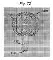
いくつかの実施形態では、補綴デバイスは、心腔内で組み立てられ、自然僧帽弁オリフィス内に埋込され、2つの自然僧帽弁尖のうちの第1のものに、または第1の自然僧帽弁尖に隣接する自然僧帽弁輪に結合される、または自由に浮遊するように構成される、区画化シートを備え、埋込されると、シートは、2つの接合する尖の間の空間を充填するように構成され、したがって、第1の自然僧帽弁尖または第1の自然僧帽弁尖に隣接する僧帽弁輪に結合されない組み立てられたシートの遊離部分は、2つの自然僧帽弁尖のうちの第2のものに向かって側方に移動し、それに対してシールし、僧帽弁逆流を低減させ、拡張期の間、第1の自然僧帽弁尖または第1の自然僧帽弁尖に隣接する自然僧帽弁輪に結合されないシートの部分は、第2の自然僧帽弁尖から離れるように側方に移動し、血液が左心房から左心室に流動することを可能にする。 In some embodiments, the prosthetic device is assembled within the heart chamber, implanted within the native mitral valve orifice, attached to the first of the two native mitral valve leaflets, or attached to the first native mitral valve leaflet. A compartmentalized sheet configured to be bound or free-floating to the native mitral annulus adjacent the mitral valve leaflets; The free portion of the assembled sheet configured to fill the space of and thus not bonded to the first native mitral valve leaflet or the mitral annulus adjacent to the first native mitral valve leaflet is divided into two It moves laterally toward and seals against the second of the native mitral valve leaflets, reduces mitral regurgitation, and during diastole either the first native mitral valve leaflet or the second one. The portion of the seat not bound to the native mitral annulus adjacent one native mitral valve leaflet moves laterally away from the second native mitral valve leaflet, allowing blood to flow from the left atrium to the left ventricle. make it possible to
いくつかの実施形態では、補綴デバイスは、心腔内で組み立てられ、自然僧帽弁オリフィス内に埋込され、2つの自然僧帽弁尖に結合されるように構成される、区画化シートを備え、埋込されると、シートは、組み立てられシートが収縮期の間に僧帽弁逆流をシールするように、2つの接合する尖の間の空間を充填するように構成される。 In some embodiments, the prosthetic device comprises a compartmentalized sheet configured to be assembled within the heart chamber, embedded within the native mitral valve orifice, and coupled to two native mitral valve leaflets. When provided and implanted, the sheet is configured to fill the space between the two coapting leaflets such that the assembled sheet seals against mitral regurgitation during systole.
いくつかの実施形態では、組み立てられた区画化シートは、逆流を低減させるように、自然弁または心房または心室壁のいずれかとの直接接触を介して、該自然僧帽弁尖の間に本デバイスを位置付けるように構成される、心室および/または心房アンカまたは支持構造を備える。 In some embodiments, the assembled compartmentalized sheet is placed between the native mitral valve leaflets through direct contact with either the native valve or the atrial or ventricular wall to reduce regurgitation. a ventricular and/or atrial anchor or support structure configured to position the
いくつかの実施形態では、組み立てられたシートの下側端部は、自然僧帽弁尖の下方の左心室内の場所に繋留される。いくつかの実施形態では、組み立てられたシートの下側端部は、左心室内の乳頭筋頭部に繋留される。いくつかの実施形態では、上側端部は、心房壁に繋留される。いくつかの実施形態では、組み立てられたシートは、略台形形状を有し、より広い部分が、僧帽弁輪に隣接し、より狭い部分が、自然僧帽弁尖の間に位置付けられる。 In some embodiments, the lower end of the assembled sheet is anchored at a location within the left ventricle below the native mitral valve leaflets. In some embodiments, the lower edge of the assembled sheet is anchored to the papillary muscle head in the left ventricle. In some embodiments, the upper end is anchored to the atrial wall. In some embodiments, the assembled sheet has a generally trapezoidal shape with the wider portion adjacent to the mitral valve annulus and the narrower portion positioned between the native mitral valve leaflets.
いくつかの実施形態では、前僧帽弁尖および後僧帽弁尖のうちの捕捉されていないものは、補綴シールデバイスが自然僧帽弁に埋込されているとき、シールデバイスに固着されない。 In some embodiments, the non-captured ones of the anterior and posterior mitral valve leaflets are not anchored to the sealing device when the prosthetic sealing device is implanted in the native mitral valve.
いくつかの実施形態では、左心室を介して自然僧帽弁領域に送達デバイスを前進させるステップは、左心室の頂点における切開部を通して左心室の中に送達デバイスを挿入するステップを含む。 In some embodiments, advancing the delivery device through the left ventricle into the native mitral valve region comprises inserting the delivery device into the left ventricle through an incision at the apex of the left ventricle.
いくつかの実施形態では、送達システムが心臓の自然僧帽弁領域に前進されるとき、アンカは、補綴シールデバイスの本体の側に沿って遠位に延在する送達カテーテル内で略直線化位置に保持される。 In some embodiments, the anchor is in a generally straightened position within a delivery catheter extending distally along a side of the body of the prosthetic sealing device when the delivery system is advanced into the native mitral region of the heart. is held to
いくつかの実施形態では、心臓の自然僧帽弁に補綴シールデバイスを埋込する方法は、送達システムを心臓の左心房から心臓の自然僧帽弁領域に前進させるステップであって、送達システムは、補綴シールデバイスを格納する、ステップと、補綴シールデバイスのアンカが送達システム内に閉じ込められないように送達システムの外側シースを近位に後退させるステップと、自然僧帽弁尖が補綴シールデバイスのアンカと送達システムとの間に位置付けられるように心臓の左心房に向かって送達システムを後退させるステップと、補綴シールデバイスの本体が送達システム内に閉じ込められないように送達システムの内側シースを近位に後退させるステップであって、本体は、収縮期および拡張期の間に本体を通した血液の流動を防止するように構成される、ステップと、心臓の自然僧帽弁領域から送達システムを除去するステップとを含む。 In some embodiments, a method of implanting a prosthetic sealing device in a native mitral valve of a heart comprises advancing a delivery system from the left atrium of the heart to a native mitral valve region of the heart, wherein the delivery system comprises: , retracting the prosthetic sealing device; proximally retracting the outer sheath of the delivery system so that the anchor of the prosthetic sealing device is not trapped within the delivery system; retracting the delivery system toward the left atrium of the heart so that it is positioned between the anchor and the delivery system; and proximally moving the inner sheath of the delivery system so that the body of the prosthetic sealing device is not trapped within the delivery system. wherein the body is configured to prevent blood flow through the body during systole and diastole; and removing the delivery system from the natural mitral valve region of the heart. and the step of
いくつかの実施形態では、左心房から自然僧帽弁領域に送達システムを前進させるステップは、左心房と右心房との間の中隔の一部における切開部を通して送達システムを前進させるステップを含む。いくつかの実施形態では、送達システムが心臓の自然僧帽弁領域に前進されるとき、アンカは、補綴シールデバイスの本体から近位に延在する送達カテーテル内の略直線化位置に保持される。 In some embodiments, advancing the delivery system from the left atrium to the native mitral valve region comprises advancing the delivery system through an incision in a portion of the septum between the left and right atria. . In some embodiments, the anchor is held in a generally straightened position within a delivery catheter extending proximally from the body of the prosthetic sealing device as the delivery system is advanced to the native mitral valve region of the heart. .
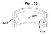
17.弁輪再成形デバイス。他の側面では、本発明は、血管に隣接する組織を再成形するために血管内に展開されるように適合される組織成形デバイス(経皮的僧帽弁輪形成デバイス等)を提供する。本デバイスは、血管壁に係合するためにカテーテルによって展開されるように適合される、第1の摩擦部材(または遠位アンカまたは返し)と、第2の摩擦部材(または近位アンカまたは返し)とを備え、本デバイスは、2つの摩擦部材に係合し、第1の摩擦部材と第2の摩擦部材との間に配置され、それらを動作可能に接続する支持構造を提供する一方、十分な表面積を用いて弁輪を緊締し、緊締力を分散させ、チーズカッタ効果を軽減する能力を提供するように適合される板ばね特徴を含む。いくつかの実施形態では、板ばね支持構造は、加えて、弁輪に対して半径方向圧縮力を付与するように構成されることができる。いくつかの実施形態では、摩擦部材は、組織と非外傷的に係合するように構成される返しである。いくつかの実施形態では、組織との係合をさらに強化するために、第1および第2の摩擦部材の間に中間摩擦部材が存在してもよい。いくつかの実施形態では、摩擦部材は、冠静脈洞に係合するように適合される。いくつかの実施形態では、摩擦部材は、冠静脈洞に係合するように適合され、デバイス全体(板ばねを含む)は、弁輪を再成形し、僧帽弁逆流を軽減するように構成される。 17. Annulus reshaping device. In another aspect, the invention provides a tissue shaping device (such as a percutaneous mitral annuloplasty device) adapted to be deployed within a blood vessel to reshape tissue adjacent to the blood vessel. The device comprises a first friction member (or distal anchor or barb) and a second friction member (or proximal anchor or barb) adapted to be deployed by the catheter to engage the vessel wall. ), wherein the device engages the two friction members and provides a support structure disposed between and operatively connecting the first friction member and the second friction member, while Includes leaf spring features adapted to provide the ability to clamp the valve annulus with sufficient surface area to distribute the clamping force and mitigate the cheese-cutter effect. In some embodiments, the leaf spring support structure can additionally be configured to impart a radial compressive force on the valve annulus. In some embodiments, the friction member is a barb configured to atraumatically engage tissue. In some embodiments, there may be an intermediate friction member between the first and second friction members to further enhance tissue engagement. In some embodiments, the friction member is adapted to engage the coronary sinus. In some embodiments, the friction member is adapted to engage the coronary sinus and the entire device (including leaf springs) is configured to reshape the valve annulus and reduce mitral regurgitation. be done.
いくつかの実施形態では、本発明は、血管に隣接する組織を再成形するために血管内に展開されるように適合される組織成形デバイス(経皮的僧帽弁輪形成デバイス等)を提供する。本デバイスは、血管壁に係合するためにカテーテルによって展開されるように適合され得る、第1のアンカと、第2のアンカと、伸縮式板ばねとを備える。2つのアンカは、展開の間に非外傷的に可逆的に係合または係脱されることができ、伸縮式板ばねは、弁輪を緊締し、加えて、弁輪に対して半径方向圧縮力を付与するように操作されることができる。いくつかの実施形態では、本方法は、伸縮式板ばねを展開構成において係止するステップを含む。いくつかの実施形態では、アンカは、冠静脈洞に係合するように適合される。 In some embodiments, the present invention provides a tissue shaping device (such as a percutaneous mitral annuloplasty device) adapted to be deployed within a blood vessel to reshape tissue adjacent to the blood vessel. do. The device comprises a first anchor, a second anchor and a telescoping leaf spring that can be adapted to be deployed by the catheter to engage the vessel wall. The two anchors can be reversibly engaged or disengaged atraumatically during deployment, and the telescoping leaf spring tightens the annulus and additionally provides radial compression against the annulus. It can be manipulated to impart force. In some embodiments, the method includes locking the telescoping leaf spring in the deployed configuration. In some embodiments, the anchor is adapted to engage the coronary sinus.
いくつかの実施形態では、本発明は、血管に隣接する組織を再成形するために血管内に展開されるように適合される組織成形デバイス(経皮的僧帽弁輪形成デバイス等)を提供する。本デバイスは、血管壁に係合するためにカテーテルによって展開されるように適合され得る、第1のアンカと、第2のアンカと、弾性拡張可能板ばねとを備える。2つのアンカは、展開の間に非外傷的に可逆的に係合または係脱されることができ、弾性拡張可能板ばねは、弁輪を緊締し、加えて、弁輪に対して半径方向圧縮力を付与するように操作されることができる。いくつかの実施形態では、アンカは、冠静脈洞に係合するように適合される。 In some embodiments, the present invention provides a tissue shaping device (such as a percutaneous mitral annuloplasty device) adapted to be deployed within a blood vessel to reshape tissue adjacent to the blood vessel. do. The device comprises a first anchor, a second anchor, and an elastically expandable leaf spring that can be adapted to be deployed by the catheter to engage the vessel wall. The two anchors can be reversibly engaged or disengaged atraumatically during deployment, and the elastically expandable leaf spring tightens the annulus as well as radially to the annulus. It can be manipulated to apply a compressive force. In some embodiments, the anchor is adapted to engage the coronary sinus.
いくつかの実施形態では、本方法は、第1の係留ステップ後にカテーテル内で第1のアンカおよび/または第2のアンカを捕捉するステップを含む。捕捉するステップは、送達構成におけるカテーテルの内側にアンカを設置するために、アンカにわたって遠位にカテーテルを前進させるステップを含んでもよい。 In some embodiments, the method includes capturing the first anchor and/or the second anchor within the catheter after the first anchoring step. The capturing step may include advancing the catheter distally over the anchor to position the anchor inside the catheter in the delivery configuration.
いくつかの実施形態では、本方法は、第1の係留ステップ後に僧帽弁輪形成デバイスに対して近位に指向される力を印加するステップを含む。いくつかの実施形態では、本方法は、第2の係留ステップ後に送達ツールから本デバイスを結合解除するステップを含む。結合解除するステップは、本デバイスからヒッチワイヤを解放し、本デバイスからテザーを除去するステップを含んでもよい。 In some embodiments, the method includes applying a proximally directed force to the mitral annuloplasty device after the first anchoring step. In some embodiments, the method includes uncoupling the device from the delivery tool after the second anchoring step. Uncoupling may include releasing the hitch wire from the device and removing the tether from the device.
いくつかの実施形態では、本デバイスは、弁輪のサイズに適応するためにより大きくまたはより小さくスケーリングされる。 In some embodiments, the device is scaled larger or smaller to accommodate the size of the annulus.
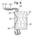
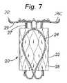
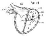
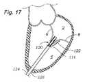
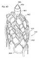
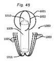
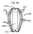
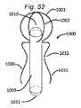
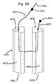
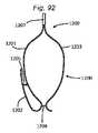
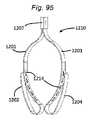
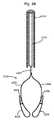
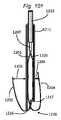
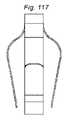
本発明の第1の具体的側面では、補綴シールデバイスは、心房板ばね区画と、心室板ばね区画とを有する板ばねを備える。区画は、基部において継合され、開放力に応答して開放し、尖受容間隙を形成し、開放力が除去されると、相互に向かって伸縮自在に閉鎖するように再構成される。本体が、板ばねの基部に取り付けられ、本体は、本体を通した血液の流動を阻止するために拡張するように構成される。 In a first specific aspect of the invention, a prosthetic sealing device comprises a leaf spring having an atrial leaf spring section and a ventricular leaf spring section. The compartments are joined at the base and reconfigured to open in response to an opening force to form a leaflet-receiving gap and telescopically close toward each other when the opening force is removed. A body is attached to the base of the leaf spring, the body configured to expand to prevent blood flow through the body.
特定の実施形態では、本体は、自己拡張構造を備えてもよい、またはバルーン拡張可能ステント様構造を備えてもよい。他の特定の実施形態では、本体は、バルーンを備えてもよく、補綴シールデバイスは、埋込後のサイズ調節を可能にするために、バルーンを遠隔で膨張させるためのインフレータまたは他の手段を備えてもよい。またさらなる特定の実施形態では、本体は、中空シャフトを備えてもよく、シャフトは、典型的には、可撓性および/または折畳可能である。代替として、本体は、中実可撓性本体を備えてもよい、圧縮可能かつ可撓性であるスポンジ様材料を含んでもよい、またはゲル様材料を含んでよい。 In certain embodiments, the body may comprise a self-expanding structure or may comprise a balloon expandable stent-like structure. In certain other embodiments, the body may comprise a balloon and the prosthetic sealing device may include an inflator or other means for remotely inflating the balloon to allow post-implantation size adjustment. You may prepare. In still further particular embodiments, the body may comprise a hollow shaft, which is typically flexible and/or collapsible. Alternatively, the body may comprise a solid flexible body, may comprise a compressible and flexible sponge-like material, or may comprise a gel-like material.
なおもさらなる特定の実施形態では、本体および板ばねは、組織内殖を助長する材料で被覆またはコーティングされてもよい。例えば、組織内殖助長材料は、ポリエステル織物を含んでもよい。 In still further specific embodiments, the body and leaf springs may be covered or coated with a material that encourages tissue ingrowth. For example, the tissue ingrowth promoting material may comprise polyester fabric.
さらに他の特定の実施形態では、板ばねは、尖を確実に把持するための非外傷性返しを備えてもよい。板ばねおよび本体は、ニッケルチタン合金等の形状記憶または超弾性材料から作製されてもよい。 In still other particular embodiments, the leaf springs may include atraumatic barbs for positive gripping of the cusps. The leaf springs and body may be made from a shape memory or superelastic material such as a nickel titanium alloy.
なおも他の特定の実施形態では、補綴シールデバイスはさらに、前尖および後尖の両方を固着させるように構成される板ばねの第2のセットを備え、本体は、板ばねの2つのセットの間に、またはその側に取り付けられてもよい。ある場合には、補綴シールデバイスはさらに、3つの三尖弁の尖のそれぞれを固着させるように構成される板ばねの第3のセットを備え、本体は、板ばねの間に、またはその側に取り付けられてもよい。 In still other particular embodiments, the prosthetic sealing device further comprises a second set of leaf springs configured to anchor both the anterior and posterior leaflets, the body comprising the two sets of leaf springs may be attached between or on the side of the In some cases, the prosthetic sealing device further comprises a third set of leaf springs configured to anchor each of the three tricuspid valve cusps, the body being between or on either side of the leaf springs. may be attached to the
さらに付加的な特定の実施形態では、補綴シールデバイスはさらに、単一の尖を固着させるように構成される板ばねの2つ以上のセットを備える。 In still additional specific embodiments, the prosthetic sealing device further comprises two or more sets of leaf springs configured to anchor a single cusp.
他の事例では、補綴シールデバイスは、埋込の間および/または後に補綴デバイスを回収するように構成される回収縫合糸を備える。随意に、補綴デバイスは、瘢痕/線維組織の形成を阻止する材料で被覆またはコーティングされてもよい。 In other instances, the prosthetic sealing device includes retrieval sutures configured to retrieve the prosthetic device during and/or after implantation. Optionally, the prosthetic device may be covered or coated with a material that inhibits scar/fibrous tissue formation.
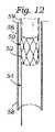
第2の具体的側面では、本発明は、僧帽弁および三尖弁を含む心臓弁における逆流を阻止するための方法を提供する。本方法は、上記に説明されるような補綴シールデバイスを提供するステップを含む。送達カニューレの送達ポートが、患者内の標的心臓弁に隣接して位置付けられ、補綴シールデバイスの心室区画が、送達カニューレの送達ポートを通して遠位に前進される。補綴シールデバイスの心室区画は、標的尖の一方の側上に位置付けられ、補綴シールデバイスの心房区画は、送達カテーテルの送達ポートを通して遠位に前進され、尖受容間隙を形成する。尖受容間隙は、標的尖にわたって位置付けられ、補綴シールデバイスはさらに、板ばね区画が標的尖にわたって伸縮自在に閉鎖し、それを捕捉するように、ポートから前進される。テザーまたは縫合糸が、随意に、板ばねを持ち上げる、および/または降下させ、標的尖の再位置付けおよび/または再捕捉を可能にするために使用されてもよい。典型的には、本体は、次いで、それを通した血液の流動を阻止するために拡張される。 In a second specific aspect, the invention provides methods for inhibiting regurgitation in heart valves, including the mitral and tricuspid valves. The method includes providing a prosthetic sealing device as described above. A delivery port of the delivery cannula is positioned adjacent a target heart valve in the patient and a ventricular compartment of the prosthetic sealing device is advanced distally through the delivery port of the delivery cannula. The ventricular compartment of the prosthetic sealing device is positioned on one side of the target cusp and the atrial compartment of the prosthetic sealing device is advanced distally through the delivery port of the delivery catheter to form the cusp-receiving gap. A leaflet-receiving gap is positioned over the target leaflet and the prosthetic sealing device is further advanced from the port such that the leaf spring section telescopically closes over and captures the target leaflet. A tether or suture may optionally be used to lift and/or lower the leaf spring to allow repositioning and/or recapture of the target leaflet. Typically, the body is then expanded to prevent blood flow therethrough.
標的心臓弁は、典型的には、僧帽弁であり、標的尖は、後尖または前尖であってもよい。単一の標的尖のみが捕捉されるとき、捕捉されていない尖は、補綴シールデバイスが埋込された後に自由に機能したままである。代替として、補綴シールデバイス上に板ばねの第2のセットを伴う第2の弁尖が、両方の尖を捕捉するために使用されてもよい。 The target heart valve is typically the mitral valve and the target leaflet may be the posterior leaflet or the anterior leaflet. When only a single target cusp is captured, the uncaptured cusp remains free to function after the prosthetic sealing device is implanted. Alternatively, a second leaflet with a second set of leaf springs on the prosthetic sealing device may be used to capture both leaflets.
以下の付番された付記は、本明細書に説明される本発明の他の実施例、側面、および実施形態を説明する。
332The following numbered appendices describe other examples, aspects, and embodiments of the inventions described herein.
332
1. 心臓の自然僧帽弁に補綴シールデバイスを埋込する方法であって、送達カテーテルを心臓の左心房から心臓の自然僧帽弁領域に前進させるステップであって、送達カテーテルは、半径方向非圧縮構成において補綴シールデバイスを格納する、ステップと、補綴シールデバイスのアンカがカテーテルから移動し、アンカの端部部分と送達カテーテルとの間に尖受容間隙を形成するように、送達カテーテルに対して遠位に補綴シールデバイスを前進させるステップと、間隙内に後僧帽弁尖または前僧帽弁尖のいずれかを位置付けるステップと、本体が弾性的に伸縮性のアンカの一部と相互作用するように、送達カテーテルから補綴シールデバイスの半径方向非圧縮本体を前進させ、間隙を縮小させ、本体とアンカの端部部分との間の尖を捕捉するステップであって、本体は、収縮期および拡張期の間に本体を通した血液の流動を防止するように構成される、ステップとを含み、前尖および後尖のうちの捕捉されていないものは、補綴シールデバイスが自然僧帽弁において意図される使用のために埋込されているとき、補綴シールデバイスに固着されない、方法。 1. A method of implanting a prosthetic sealing device in the native mitral valve of the heart, comprising advancing a delivery catheter from the left atrium of the heart into the native mitral valve region of the heart, the delivery catheter being radially incompressible. retracting the prosthetic sealing device in a configuration; and distally relative to the delivery catheter such that the anchor of the prosthetic sealing device moves from the catheter to form a leaflet-receiving gap between the end portion of the anchor and the delivery catheter. advancing the prosthetic sealing device into position; positioning either the posterior mitral valve leaflet or the anterior mitral valve leaflet within the gap; and advancing the radially incompressible body of the prosthetic sealing device from the delivery catheter to reduce the gap and capture the cusp between the body and the end portion of the anchor, the body undergoing systole and diastole configured to prevent the flow of blood through the body during the period, wherein the uncaught one of the anterior and posterior leaflets is such that the prosthetic sealing device is intended at the native mitral valve. A method of not adhering to a prosthetic sealing device when implanted for use.
2. 左心房から自然僧帽弁を通して送達カテーテルを前進させるステップは、左心房と右心房との間の中隔の一部における切開部を通して送達カテーテルを前進させるステップを含む、付記1に記載の方法。 2.
3. 送達カテーテルが心臓の自然僧帽弁領域に前進されるとき、アンカは、補綴シールデバイスの本体から遠位に延在する送達カテーテル内で略直線化位置に保持される、付記1に記載の方法。 3.
4. 本デバイスは、送達カテーテル内で側方に圧縮され、送達時に自己拡張する、付記1に記載の方法。 4. 10. The method of
5. 本デバイスは、送達カテーテル内で側方に圧縮され、送達時に機械的に拡張される、付記1に記載の方法。 5.
6. 本デバイスは、送達カテーテル内で折畳され、送達時に自己折畳解除する、付記1に記載の方法。 6.
7. 本デバイスは、送達カテーテル内で収縮構成にあり、送達の間に膨張される、付記1に記載の方法。 7.
8. 本デバイスは、送達カテーテル内で収縮構成にあり、送達後に膨張される、付記1に記載の方法。 8.
9. 本体は、ワイヤ、ロッド、平坦ワイヤ、シート金属、またはそれらの組み合わせを含み、本体は、返しまたは尖の確実な捕捉を助長する特徴を備える、付記1に記載の方法。 9.
10. アンカは、ワイヤ、ロッド、平坦ワイヤ、シート金属、またはそれらの組み合わせを含む、付記1に記載の方法。 10.
11. 本デバイスは、ワイヤ、ロッド、平坦ワイヤ、シート金属、またはそれらの組み合わせを含み、本デバイスは、返しまたは尖の確実な捕捉を助長する特徴を備える、付記1に記載の方法。 11. 10. The method of
12. 補綴デバイス材料は、金属、ポリマー、セラミック、超弾性、形状記憶、ガス、液体、有機材料、またはそれらの組み合わせを含む、付記1に記載の方法。 12.
13. 補綴デバイスは、織物カバー、ポリマーまたは金属コーティング、薬物、有機材料、またはそれらの組み合わせで完全または部分的に被覆される、付記1に記載の方法。 13.
14. 自然僧帽弁に補綴シールデバイスを埋込する方法であって、左心室を介して自然僧帽弁領域に送達デバイスを前進させるステップであって、送達カテーテルは、非圧縮構成における補綴シールデバイスを格納する、ステップと、尖受容間隙がアンカの端部部分と送達デバイスとの間に形成されるように、補綴シールデバイスの本体が非圧縮構成にある間、補綴シールデバイスのアンカが送達デバイスから半径方向に移動することを可能にするステップと、尖が本体とアンカとの間に捕捉されるように、間隙内に後僧帽弁尖または前僧帽弁尖のいずれかを位置付けるステップであって、本体は、収縮期および拡張期の間に本体を通した血液の流動を防止するように構成される、ステップとを含み、前僧帽弁尖および後僧帽弁尖のうちの捕捉されていないものは、補綴シールデバイスが自然僧帽弁において意図される使用のために埋込されているとき、補綴シールデバイスに固着されない、方法。 14. A method of implanting a prosthetic sealing device in a native mitral valve comprising advancing a delivery device through the left ventricle into the native mitral valve region, wherein a delivery catheter moves the prosthetic sealing device in an uncompressed configuration. retracting and retracting the anchor of the prosthetic sealing device from the delivery device while the body of the prosthetic sealing device is in the uncompressed configuration such that a leaflet-receiving gap is formed between the end portion of the anchor and the delivery device; and positioning either the posterior mitral leaflet or the anterior mitral leaflet within the gap so that the leaflet is trapped between the body and the anchor. and the body is configured to prevent blood flow through the body during systole and diastole, and the captured one of the anterior and posterior mitral valve leaflets. A method that does not adhere to the prosthetic sealing device when the prosthetic sealing device is implanted for its intended use in the native mitral valve.
15. 左心室を介して自然僧帽弁領域に送達デバイスを前進させるステップは、左心室の頂点における切開部を通して左心室の中に送達デバイスを挿入するステップを含む、付記14に記載の方法。 15. 15. The method of
16. 左心室から自然僧帽弁を通して送達カテーテルを前進させるステップは、大動脈を通して送達カテーテルを前進させるステップを含む、付記14に記載の方法。 16. 15. The method of
17. 送達カテーテルが心臓の自然僧帽弁領域に前進されるとき、アンカは、送達カテーテル内の略直線化位置に保持される、付記14に記載の方法。 17. Clause 15. The method of
18. 補綴デバイスを埋込する方法であって、送達装置を使用して埋込場所に非圧縮構成における補綴デバイスを前進させるステップであって、補綴デバイスは、スペーサ本体と、第1のアンカと、第2のアンカとを備え、アンカは、伸縮自在に付勢され、第1および第2の構成を有する、ステップと、補綴シールデバイスのアンカが第1の構成においてカテーテルから移動し、第1のアンカの端部部分と送達カテーテルとの間に尖受容間隙を形成するように、送達カテーテルに対して遠位に補綴シールデバイスを前進させるステップと、第1のアンカによって形成される間隙内に後僧帽弁尖または前僧帽弁尖のいずれかを位置付けるステップと、第1のアンカが第2の構成に遷移し、第2のアンカが第1の位置に遷移するように、送達カテーテルに対して遠位に補綴シールデバイスを操作するステップであって、第1のアンカは、第1の尖を伸縮自在に捕捉する、ステップと、第2のアンカによって形成される間隙内に第2の僧帽弁尖を位置付けるステップと、第2のアンカが第2の構成に遷移するように、送達カテーテルに対して遠位に補綴シールデバイスを操作するステップであって、第2のアンカは、第2の尖を伸縮自在に捕捉する、ステップと、本体が弾性的に伸縮性のアンカの一部と相互作用するように、送達カテーテルから補綴シールデバイスの非圧縮本体を前進させるステップと、本体とアンカの端部部分との間の尖を捕捉するステップであって、本体は、収縮期および拡張期の間に本体を通した血液の流動を防止するように構成される、ステップとを含み、補綴シールデバイスは、自然僧帽弁において意図される使用のために埋込される、方法。 18. A method of implanting a prosthetic device comprising the steps of advancing the prosthetic device in an uncompressed configuration to an implantation site using a delivery apparatus, the prosthetic device comprising a spacer body, a first anchor and a first anchor. two anchors, the anchors being telescopically biased and having first and second configurations; and the anchors of the prosthetic sealing device displaced from the catheter in the first configuration and the first anchors. advancing the prosthetic sealing device distally with respect to the delivery catheter to form a leaflet-receiving gap between the end portion of the posterior and the delivery catheter; positioning either the mitral leaflet or the anterior mitral leaflet; and relative to the delivery catheter such that the first anchor transitions to the second configuration and the second anchor transitions to the first position. manipulating the prosthetic sealing device distally, wherein the first anchor telescopically captures the first cusp; positioning the leaflets; and manipulating the prosthetic sealing device distal to the delivery catheter such that the second anchor transitions to the second configuration, the second anchor telescopically capturing the cusps; advancing the non-compressed body of the prosthetic sealing device from the delivery catheter such that the body elastically interacts with a portion of the stretchable anchor; capturing the cusps between the end portions, the body being configured to prevent blood flow through the body during systole and diastole; and A method, wherein the device is implanted for intended use in the native mitral valve.
19. 左心房から自然僧帽弁を通して送達カテーテルを前進させるステップは、左心房と右心房との間の中隔の一部における切開部を通して送達カテーテルを前進させるステップを含む、付記18に記載の方法。 19. 19. The method of Clause 18, wherein advancing the delivery catheter from the left atrium through the native mitral valve comprises advancing the delivery catheter through an incision in a portion of the septum between the left and right atria.
20. 送達カテーテルが心臓の自然僧帽弁領域に前進されるとき、アンカは、送達カテーテル内の略直線化位置に保持される、付記18に記載の方法。 20. Clause 19. The method of Clause 18, wherein the anchor is held in a substantially straightened position within the delivery catheter as the delivery catheter is advanced into the heart's native mitral valve region.
21. 左心室を介して自然僧帽弁領域に送達デバイスを前進させるステップは、左心室の頂点における切開部を通して左心室の中に送達デバイスを挿入するステップを含む、付記18に記載の方法。 21. 19. The method of paragraph 18, wherein advancing the delivery device through the left ventricle into the native mitral valve region comprises inserting the delivery device into the left ventricle through an incision at the apex of the left ventricle.
22. 左心室から自然僧帽弁を通して送達カテーテルを前進させるステップは、大動脈を通して送達カテーテルを前進させるステップを含む、付記18に記載の方法。
側方付記22. 19. The method of Clause 18, wherein advancing the delivery catheter from the left ventricle through the native mitral valve comprises advancing the delivery catheter through the aorta.
Side note
23. 心臓の自然僧帽弁に補綴シールデバイスを埋込する方法であって、送達カテーテルを心臓の左心房から心臓の自然僧帽弁領域に前進させるステップであって、送達カテーテルは、側方圧縮構成において補綴シールデバイスを格納するステップと、補綴シールデバイスのアンカがカテーテルから移動し、アンカの端部部分と送達カテーテルとの間に尖受容間隙を形成するように、送達カテーテルに対して遠位に補綴シールデバイスを前進させるステップと、間隙内に後僧帽弁尖または前僧帽弁尖のいずれかを位置付けるステップと、本体がアンカの端部部分に向かって側方に自己拡張するように、送達カテーテルから補綴シールデバイスの側方圧縮本体を前進させ、間隙を縮小させ、本体とアンカの端部部分との間の尖を捕捉するステップであって、本体は、収縮期および拡張期の間に本体を通した血液の流動を防止するように構成される、ステップとを含み、前尖および後尖のうちの捕捉されていないものは、補綴シールデバイスが自然僧帽弁において意図される使用のために埋込されているとき、補綴シールデバイスに固着されない、方法。 23. A method of implanting a prosthetic sealing device in the native mitral valve of the heart, comprising advancing a delivery catheter from the left atrium of the heart into the native mitral valve region of the heart, the delivery catheter being in a lateral compression configuration. retracting the prosthetic sealing device in and distally relative to the delivery catheter such that the anchor of the prosthetic sealing device is displaced from the catheter to form a leaflet-receiving gap between the end portion of the anchor and the delivery catheter. advancing a prosthetic sealing device; positioning either the posterior mitral valve leaflet or the anterior mitral valve leaflet within the gap; and causing the body to self-expand laterally toward the end portion of the anchor; advancing a laterally compressed body of a prosthetic sealing device from the delivery catheter to reduce the gap and capture the cusp between the body and the end portion of the anchor, the body compressing during systole and diastole; configured to prevent the flow of blood through the body to and from the uncaught one of the anterior and posterior leaflets of the prosthetic sealing device for its intended use in the native mitral valve. A method that does not adhere to a prosthetic sealing device when implanted for the purpose.
24. 自然僧帽弁に補綴シールデバイスを埋込する方法であって、左心室を介して自然僧帽弁領域に送達デバイスを前進させるステップであって、送達カテーテルは、側方圧縮構成において補綴シールデバイスを格納する、ステップと、尖受容間隙がアンカの端部部分と送達デバイスとの間に形成されるように、補綴シールデバイスの本体が圧縮構成にある間、補綴シールデバイスのアンカが送達デバイスから側方に移動することを可能にするステップと、間隙内に後僧帽弁尖または前僧帽弁尖のいずれかを位置付けるステップと、尖が本体とアンカとの間に捕捉されるように、補綴シールデバイスの本体が側方に自己拡張することを可能にするステップであって、本体は、収縮期および拡張期の間に本体を通した血液の流動を防止するように構成される、ステップとを含み、前僧帽弁尖および後僧帽弁尖のうちの捕捉されていないものは、補綴シールデバイスが自然僧帽弁において意図される使用のために埋込されているとき、補綴シールデバイスに固着されない、方法。 24. A method of implanting a prosthetic sealing device in a native mitral valve comprising advancing a delivery device through the left ventricle into the native mitral valve region, wherein the delivery catheter extends the prosthetic sealing device in a laterally compressed configuration. and retracting the anchor of the prosthetic sealing device from the delivery device while the body of the prosthetic sealing device is in the compressed configuration such that a leaflet-receiving gap is formed between the end portion of the anchor and the delivery device. allowing lateral movement; positioning either the posterior mitral valve leaflet or the anterior mitral valve leaflet within the gap; allowing the body of the prosthetic sealing device to laterally self-expand, wherein the body is configured to prevent blood flow through the body during systole and diastole; and the non-captured ones of the anterior and posterior mitral valve leaflets form a prosthetic seal when the prosthetic sealing device is implanted for its intended use in the native mitral valve. A method that is not attached to the device.
25. 補綴デバイスを埋込する方法であって、送達装置を使用して埋込場所に側方圧縮構成における補綴デバイスを前進させるステップであって、補綴デバイスは、スペーサ本体と、第1のアンカと、第2のアンカとを備え、アンカは、伸縮自在に付勢され、第1および第2の構成を有する、ステップと、補綴シールデバイスのアンカが第1の構成においてカテーテルから移動し、第1のアンカの端部部分と送達カテーテルとの間に尖受容間隙を形成するように、送達カテーテルに対して遠位に補綴シールデバイスを前進させるステップと、第1のアンカによって形成される間隙内に後僧帽弁尖または前僧帽弁尖のいずれかを位置付けるステップと、第1のアンカが第2の構成に遷移し、第2のアンカが第1の構成に遷移するように、送達カテーテルに対して遠位に補綴シールデバイスを前進させるステップであって、第1のアンカは、第1の尖を伸縮自在に捕捉する、ステップと、第2のアンカによって形成される間隙内に第2の僧帽弁尖を位置付けるステップと、第2のアンカが第2の構成に遷移し、尖を伸縮自在に捕捉するように、送達カテーテルに対して遠位に補綴シールデバイスを前進させるステップと、本体が伸縮自在に側方に拡張し、弾性的に伸縮性のアンカの一部と相互作用し、尖とさらに係合するように、送達カテーテルから補綴シールデバイスの側方圧縮本体を前進させるステップと、本体とアンカの端部部分との間の尖を捕捉するステップであって、本体は、収縮期および拡張期の間に本体を通した血液の流動を防止するように構成される、ステップとを含み、補綴シールデバイスは、自然僧帽弁において意図される使用のために埋込される、方法。
(支持を伴うスペーサ付記)25. A method of implanting a prosthetic device comprising advancing the prosthetic device in a laterally compressed configuration to an implantation site using a delivery apparatus, the prosthetic device comprising a spacer body, a first anchor, a second anchor, the anchor telescopically biased and having first and second configurations; and the anchor of the prosthetic sealing device displaced from the catheter in the first configuration and the first advancing a prosthetic sealing device distally relative to the delivery catheter to form a leaflet-receiving gap between the end portion of the anchor and the delivery catheter; positioning either the mitral valve leaflet or the anterior mitral valve leaflet; distally advancing a prosthetic sealing device with a first anchor telescopically capturing the first cusp; positioning the capsular leaflet; advancing the prosthetic sealing device distally relative to the delivery catheter such that the second anchor transitions to a second configuration and telescopically captures the leaflet; advancing a lateral compression body of the prosthetic sealing device from the delivery catheter so as to telescopically expand laterally, resiliently interact with a portion of the stretchable anchor, and further engage the cusp; capturing a cusp between the body and an end portion of the anchor, the body configured to prevent blood flow through the body during systole and diastole; A method comprising: a prosthetic sealing device being implanted for intended use in a native mitral valve.
(Spacer added with support)
26. 心臓の自然僧帽弁に補綴シールデバイスを埋込する方法であって、送達カテーテルを心臓の左心房から心臓の自然僧帽弁領域に前進させるステップであって、送達カテーテルは、可撓性空間占有構成において補綴シールデバイスを格納し、補綴シールデバイスは、可撓性本体と、心房支持構造と、心室支持構造とを備える、ステップと、補綴シールデバイスの心室支持構造がカテーテルから移動し、心室空間内で拡張するように、送達カテーテルに対して遠位に補綴シールデバイスを前進させるステップと、本体が弁輪および/または尖接合空間に跨架するように、送達カテーテルから補綴シールデバイスを前進させるステップと、送達カテーテルを後退させ、心房支持構造を解放するステップであって、それによって、心房支持構造は、心房空間内で伸縮自在に拡張する、ステップとを含み、本体は、収縮期および拡張期の間に本体を通した血液の流動を防止するように構成され、補綴デバイスは、補綴シールデバイスが自然僧帽弁において意図される使用のために埋込されているとき、2つの支持構造によって制約されるような限定された運動を可能にされる、方法。 26. A method of implanting a prosthetic sealing device in the native mitral valve of the heart, comprising advancing a delivery catheter from the left atrium of the heart into the native mitral valve region of the heart, the delivery catheter extending through a flexible space. storing the prosthetic sealing device in an occupied configuration, the prosthetic sealing device comprising a flexible body, an atrial support structure, and a ventricular support structure; advancing the prosthetic sealing device distally relative to the delivery catheter to expand within the space; and retracting the delivery catheter to release the atrial support structure, whereby the atrial support structure telescopically expands within the atrial space, the body moving during systole and Configured to prevent blood flow through the body during diastole, the prosthetic device has two supports when the prosthetic sealing device is implanted for its intended use in the native mitral valve. A method that allows limited movement as constrained by the structure.
27. 自然僧帽弁に補綴シールデバイスを埋込する方法であって、左心室を介して自然僧帽弁領域に、および左心房の中に送達デバイスを前進させるステップであって、送達カテーテルは、可撓性空間占有構成において補綴シールデバイスを格納し、補綴シールデバイスは、可撓性本体と、心房支持構造と、心室支持構造とを備える、ステップと、左心房内で心房支持構造を解放するように送達カテーテルを操作するステップであって、それによって、心房支持構造は、左心房内で伸縮自在に拡張する、ステップと、本体が弁輪および/または尖接合空間に跨架するように、補綴デバイスをさらに展開するように送達カテーテルを操作するステップと、心室支持構造を解放するように送達カテーテルを操作するステップであって、それによって、心室支持構造は、心室空間内で伸縮自在に拡張する、ステップとを含み、本体は、収縮期および拡張期の間に本体を通した血液の流動を防止するように構成され、補綴デバイスは、補綴シールデバイスが自然僧帽弁において意図される使用のために埋込されているとき、2つの支持構造によって制約されるような限定された運動を可能にされる、方法。
(心房および/または心室支持構造を伴う拡張可能スペーサ付記)27. A method of implanting a prosthetic sealing device in a native mitral valve, comprising advancing a delivery device through the left ventricle into the native mitral valve region and into the left atrium, wherein the delivery catheter is capable of storing a prosthetic sealing device in a flexible space-occupying configuration, the prosthetic sealing device comprising a flexible body, an atrial support structure, and a ventricular support structure; and to release the atrial support structure within the left atrium. manipulating the delivery catheter to thereby telescopically expand the atrial support structure within the left atrium and the prosthesis so that the body spans the annulus and/or apical junction space; Manipulating the delivery catheter to further deploy the device and manipulating the delivery catheter to release the ventricular support structure, whereby the ventricular support structure telescopically expands within the ventricular space. and wherein the body is configured to prevent the flow of blood through the body during systole and diastole, and the prosthetic device is adapted for the intended use of the prosthetic sealing device in the native mitral valve. A method of allowing limited movement as constrained by two support structures when implanted for.
(expandable spacer with atrial and/or ventricular support structure)
28. 心臓の自然僧帽弁に補綴シールデバイスを埋込する方法であって、送達カテーテルを心臓の左心房から心臓の自然僧帽弁領域に前進させるステップであって、送達カテーテルは、圧縮構成において補綴シールデバイスを格納し、補綴シールデバイスは、本体と、心房支持構造と、心室支持構造とを備える、ステップと、補綴シールデバイスの心室支持構造がカテーテルから移動し、心室空間内で拡張するように、送達カテーテルに対して遠位に補綴シールデバイスを前進させるステップと、本体が伸縮自在に拡張し、弁輪および/または尖接合空間に跨架するように、送達カテーテルから補綴シールデバイスを前進させるステップと、送達カテーテルを後退させ、心房支持構造を解放するステップであって、それによって、心房支持構造は、心房空間内で伸縮自在に拡張する、ステップとを含み、拡張された本体は、収縮期および拡張期の間に本体を通した血液の流動を防止するように構成され、補綴デバイスは、補綴シールデバイスが自然僧帽弁において意図される使用のために埋込されているとき、2つの支持構造によって制約されるような限定された運動を可能にされる、方法。 28. A method of implanting a prosthetic sealing device in the native mitral valve of the heart, comprising advancing a delivery catheter from the left atrium of the heart into the native mitral valve region of the heart, the delivery catheter moving the prosthesis in a compressed configuration. Retracting a sealing device, the prosthetic sealing device comprising a body, an atrial support structure, and a ventricular support structure, steps such that the ventricular support structure of the prosthetic sealing device moves from the catheter and expands within the ventricular space. advancing the prosthetic sealing device distally relative to the delivery catheter; and advancing the prosthetic sealing device from the delivery catheter such that the body telescopically expands and spans the annulus and/or apical junction space. and retracting the delivery catheter to release the atrial support structure, whereby the atrial support structure telescopically expands within the atrial space, the expanded body contracting. 2. The prosthetic device is configured to prevent blood flow through the body during phase and diastole, and the prosthetic device is configured to prevent blood flow through the body during phase and diastole, and the prosthetic device is configured to prevent blood from flowing through the body during phase and diastole; A method that allows limited movement as constrained by a single support structure.
29. 自然僧帽弁に補綴シールデバイスを埋込する方法であって、左心室を介して自然僧帽弁領域に、および左心房の中に送達デバイスを前進させるステップであって、送達カテーテルは、圧縮構成において補綴シールデバイスを格納し、補綴シールデバイスは、本体と、心房支持構造と、心室支持構造とを備える、ステップと、左心房内で心房支持構造を解放するように送達カテーテルを操作するステップであって、それによって、心房支持構造は、左心房内で伸縮自在に拡張する、ステップと、本体が伸縮自在に拡張し、弁輪および/または尖接合空間に跨架するように、補綴デバイスをさらに展開するように送達カテーテルを操作するステップと、心室支持構造を解放するように送達カテーテルを操作するステップであって、それによって、心室支持構造は、心室空間内で伸縮自在に拡張する、ステップとを含み、本体は、収縮期および拡張期の間に本体を通した血液の流動を防止するように構成され、補綴デバイスは、補綴シールデバイスが自然僧帽弁において意図される使用のために埋込されているとき、2つの支持構造によって制約されるような限定された運動を可能にされる、方法。
(バルーンスペーサ付記)29. A method of implanting a prosthetic sealing device in a native mitral valve comprising advancing a delivery device through the left ventricle into the native mitral valve region and into the left atrium, the delivery catheter being compressed storing a prosthetic sealing device in a configuration, the prosthetic sealing device comprising a body, an atrial support structure, and a ventricular support structure; and manipulating the delivery catheter to release the atrial support structure within the left atrium. wherein the atrial support structure telescopically expands within the left atrium and the prosthetic device such that the body telescopically expands and spans the annulus and/or apical junction space. and manipulating the delivery catheter to release the ventricular support structure, whereby the ventricular support structure telescopically expands within the ventricular space. and wherein the body is configured to prevent blood flow through the body during systole and diastole, and the prosthetic device is adapted for use in the native mitral valve for which the prosthetic sealing device is intended. A method of allowing limited motion as constrained by two support structures when implanted in a.
(Balloon spacer attached)
30. 心臓の自然僧帽弁に補綴シールデバイスを埋込する方法であって、送達カテーテルを心臓の左心房から心臓の自然僧帽弁領域に前進させるステップであって、送達カテーテルは、収縮構成において補綴シールデバイスを格納する、ステップと、膨張可能本体と、アンカとを備えるステップであって、本体およびアンカは、ともに取り付けられる、ステップと、補綴シールデバイスのアンカがカテーテルから移動し、アンカの端部部分と送達カテーテルとの間に尖受容間隙を形成するように、送達カテーテルに対して遠位に補綴シールデバイスを前進させるステップと、間隙内に後僧帽弁尖または前僧帽弁尖のいずれかを位置付けるステップと、送達カテーテルから補綴シールデバイスの収縮された本体を前進させ、本体がアンカの端部部分に向かって膨張するように本体を膨張させ、間隙を縮小させ、本体とアンカの端部部分との間の尖を捕捉するステップであって、本体は、収縮期および拡張期の間に本体を通した血液の流動を防止するように構成される、ステップとを含み、前尖および後尖のうちの捕捉されていないものは、補綴シールデバイスが自然僧帽弁において意図される使用のために埋込されているとき、補綴シールデバイスに固着されない、方法。 30. A method of implanting a prosthetic sealing device in the native mitral valve of the heart, comprising advancing a delivery catheter from the left atrium of the heart into the native mitral valve region of the heart, the delivery catheter moving the prosthesis in a contracted configuration. retracting a sealing device comprising: an inflatable body; and an anchor, wherein the body and the anchor are attached together; moving the anchor of the prosthetic sealing device from the catheter; advancing a prosthetic sealing device distally relative to the delivery catheter to form a leaflet-receiving gap between the segment and the delivery catheter; and advancing the contracted body of the prosthetic sealing device from the delivery catheter, inflating the body so that it expands toward the end portion of the anchor, reducing the gap, and separating the ends of the body and the anchor. capturing the cusps between the anterior cusps and the anterior cusps, the body being configured to prevent blood flow through the body during systole and diastole; A method, wherein the uncaptured one of the posterior leaflets is not adhered to the prosthetic sealing device when the prosthetic sealing device is implanted for its intended use in the native mitral valve.
31. 左心房から自然僧帽弁を通して送達カテーテルを前進させるステップは、左心房と右心房との間の中隔の一部における切開部を通して送達カテーテルを前進させるステップを含む、付記30に記載の方法。 31. 31. The method of
32. 送達カテーテルが心臓の自然僧帽弁領域に前進されるとき、アンカは、補綴シールデバイスの本体から遠位に延在する送達カテーテル内で略直線化位置に保持される、付記30に記載の方法。 32. 31. The method of
33. 本デバイスの本体は、送達カテーテル内で収縮構成にあり、送達の間に膨張される、付記30に記載の方法。 33. 31. The method of
34. 本デバイスの本体は、送達カテーテル内で収縮構成にあり、送達後に膨張される、付記30に記載の方法。 34. 31. The method of
35. 本デバイスの本体は、送達カテーテル内で収縮構成にあり、送達の間に膨張される、付記30に記載の方法。 35. 31. The method of
36. 本デバイスは、送達カテーテル内で収縮構成にあり、送達後に膨張される、付記30に記載の方法。 36. 31. The method of
37. 自然僧帽弁に補綴シールデバイスを埋込する方法であって、左心室を介して自然僧帽弁領域に送達デバイスを前進させるステップであって、送達カテーテルは、収縮構成において補綴シールデバイスを格納する、ステップと、膨張可能本体と、アンカとを備えるステップであって、本体およびアンカは、ともに取り付けられる、ステップと、尖受容間隙がアンカの端部部分と送達デバイスとの間に形成されるように、補綴シールデバイスの本体が収縮構成にある間、補綴シールデバイスのアンカが送達デバイスから伸縮自在に移動することを可能にするステップと、間隙内に後僧帽弁尖または前僧帽弁尖のいずれかを位置付けるステップと、尖が本体とアンカとの間に捕捉されるように、膨張するように補綴シールデバイスの本体を膨張させるステップであって、本体は、収縮期および拡張期の間に本体を通した血液の流動を防止するように構成される、ステップとを含み、前僧帽弁尖および後僧帽弁尖のうちの捕捉されていないものは、補綴シールデバイスが自然僧帽弁において意図される使用のために埋込されているとき、補綴シールデバイスに固着されない、方法。 37. A method of implanting a prosthetic sealing device in a native mitral valve, comprising advancing a delivery device through the left ventricle into the native mitral valve region, wherein a delivery catheter retracts the prosthetic sealing device in a contracted configuration. and an expandable body and an anchor, wherein the body and the anchor are attached together, and a leaflet-receiving gap is formed between the end portion of the anchor and the delivery device. allowing the anchor of the prosthetic sealing device to telescopically move from the delivery device while the body of the prosthetic sealing device is in the contracted configuration; positioning any of the cusps; and inflating the body of the prosthetic sealing device such that the cusps are captured between the body and the anchor, the body being in systolic and diastolic states. configured to prevent blood flow through the body between the uncaught ones of the anterior mitral valve leaflets and the posterior mitral valve leaflets so that the prosthetic sealing device is in contact with the natural mitral valve leaflet; A method that does not adhere to the prosthetic sealing device when implanted for its intended use in the capillary valve.
38. 補綴デバイスを埋込する方法であって、送達装置を使用して埋込場所に側方圧縮構成における補綴デバイスを前進させるステップであって、補綴デバイスは、膨張可能スペーサ本体と、第1のアンカと、第2のアンカとを備え、アンカは、伸縮自在に付勢され、第1および第2の構成を有する、ステップと、補綴シールデバイスのアンカが第1の構成においてカテーテルから移動し、第1のアンカの端部部分と送達カテーテルとの間に尖受容間隙を形成するように、送達カテーテルに対して遠位に補綴シールデバイスを前進させるステップと、第1のアンカによって形成される間隙内に後僧帽弁尖または前僧帽弁尖のいずれかを位置付けるステップと、第1のアンカが第2の構成に遷移し、第2のアンカが第1の構成に遷移するように、送達カテーテルに対して遠位に補綴シールデバイスを前進させるステップであって、第1のアンカは、第1の尖を伸縮自在に捕捉する、ステップと、第2のアンカによって形成される間隙内に第2の僧帽弁尖を位置付けるステップと、第2のアンカが第2の構成に遷移し、尖を伸縮自在に捕捉するように、送達カテーテルに対して遠位に補綴シールデバイスを前進させるステップと、送達カテーテルから補綴シールデバイスの収縮された本体を前進させ、本体がアンカの端部部分に向かって膨張するように本体を膨張させ、尖とさらに係合させ、本体とアンカの端部部分との間の尖を確実に捕捉するステップであって、本体は、収縮期および拡張期の間に本体を通した血液の流動を防止するように構成される、ステップとを含み、補綴シールデバイスは、自然僧帽弁において意図される使用のために埋込される、方法。 38. A method of implanting a prosthetic device comprising advancing the prosthetic device in a laterally compressed configuration to an implantation site using a delivery apparatus, the prosthetic device comprising an inflatable spacer body and a first anchor. and a second anchor, the anchor being telescopically biased and having first and second configurations; the anchor of the prosthetic sealing device moving from the catheter in the first configuration; advancing a prosthetic sealing device distally with respect to the delivery catheter to form a leaflet-receiving gap between an end portion of one anchor and the delivery catheter; positioning either the posterior mitral valve leaflet or the anterior mitral valve leaflet in the delivery catheter such that the first anchor transitions to the second configuration and the second anchor transitions to the first configuration; advancing a prosthetic sealing device distally relative to the first anchor, wherein the first anchor telescopically captures the first cusp; and advancing the prosthetic sealing device distally relative to the delivery catheter such that the second anchor transitions to a second configuration and telescopically captures the leaflets; Advancing the contracted body of the prosthetic sealing device from the delivery catheter, inflating the body so that it expands toward the end portion of the anchor, further engages the cusps, and engages the body and the end portion of the anchor. the body is configured to prevent blood flow through the body during systole and diastole; the prosthetic sealing device comprising: A method implanted for intended use in a native mitral valve.
39. 左心房から自然僧帽弁を通して送達カテーテルを前進させるステップは、左心房と右心房との間の中隔の一部における切開部を通して送達カテーテルを前進させるステップを含む、付記38に記載の方法。 39. 39. The method of
40. 送達カテーテルが心臓の自然僧帽弁領域に前進されるとき、アンカは、送達カテーテル内の略直線化位置に保持される、付記38に記載の方法。 40. Clause 39. The method of
41. 左心室を介して自然僧帽弁領域に送達デバイスを前進させるステップは、左心室の頂点における切開部を通して左心室の中に送達デバイスを挿入するステップを含む、付記38に記載の方法。 41. 39. The method of
42. 左心室から自然僧帽弁を通して送達カテーテルを前進させるステップは、大動脈を通して送達カテーテルを前進させるステップを含む、付記38に記載の方法。
支持を伴う膨張可能スペーサ42. 39. The method of
Inflatable spacer with support
43. 心臓の自然僧帽弁に補綴シールデバイスを埋込する方法であって、送達カテーテルを心臓の左心房から心臓の自然僧帽弁領域に前進させるステップであって、送達カテーテルは、収縮構成において補綴シールデバイスを格納し、補綴シールデバイスは、膨張可能本体と、心房支持構造と、心室支持構造とを備える、ステップと、補綴シールデバイスの心室支持構造がカテーテルから移動し、心室空間内で拡張するように、送達カテーテルに対して遠位に補綴シールデバイスを前進させるステップと、本体が弁輪および/または尖接合空間に跨架するように、送達カテーテルから補綴シールデバイスを前進させるステップと、本体を膨張させるステップと、送達カテーテルを後退させ、心房支持構造を解放するステップであって、それによって、心房支持構造は、心房空間内で伸縮自在に拡張する、ステップとを含み、膨張された本体は、収縮期および拡張期の間に本体を通した血液の流動を防止するように構成され、補綴デバイスは、補綴シールデバイスが自然僧帽弁において意図される使用のために埋込されているとき、2つの支持構造によって制約されるような限定された運動を可能にされる、方法。 43. A method of implanting a prosthetic sealing device in the native mitral valve of the heart, comprising advancing a delivery catheter from the left atrium of the heart into the native mitral valve region of the heart, the delivery catheter moving the prosthesis in a contracted configuration. Retracting a sealing device, the prosthetic sealing device comprising an inflatable body, an atrial support structure, and a ventricular support structure, a step and the ventricular support structure of the prosthetic sealing device displaces from the catheter and expands within the ventricular space. advancing the prosthetic sealing device distally with respect to the delivery catheter; advancing the prosthetic sealing device from the delivery catheter such that the body spans the annulus and/or the coaptation space; and retracting the delivery catheter to release the atrial support structure, whereby the atrial support structure telescopically expands within the atrial space, the inflated body is configured to prevent blood flow through the body during systole and diastole, and the prosthetic device is implanted for its intended use in the native mitral valve. A method when allowed limited motion as constrained by two support structures.
44. 自然僧帽弁に補綴シールデバイスを埋込する方法であって、左心室を介して自然僧帽弁領域に、および左心房の中に送達デバイスを前進させるステップであって、送達カテーテルは、収縮構成において補綴シールデバイスを格納し、補綴シールデバイスは、膨張可能本体と、心房支持構造と、心室支持構造とを備える、ステップと、左心房内で心房支持構造を解放するように送達カテーテルを操作するステップであって、それによって、心房支持構造は、左心房内で伸縮自在に拡張する、ステップと、本体が弁輪および/または尖接合空間に跨架するように、補綴デバイスをさらに展開するように送達カテーテルを操作するステップと、本体を膨張させるステップと、心室支持構造を解放するように送達カテーテルを操作するステップであって、それによって、心室支持構造は、心室空間内で伸縮自在に拡張する、ステップとを含み、本体は、収縮期および拡張期の間に本体を通した血液の流動を防止するように構成され、補綴デバイスは、補綴シールデバイスが自然僧帽弁において意図される使用のために埋込されているとき、2つの支持構造によって制約されるような限定された運動を可能にされる、方法。
板ばね付記44. A method of implanting a prosthetic sealing device in a native mitral valve comprising advancing a delivery device through the left ventricle into the native mitral valve region and into the left atrium, wherein the delivery catheter is deflated. storing a prosthetic sealing device in a configuration, the prosthetic sealing device comprising an inflatable body, an atrial support structure, and a ventricular support structure; and operating the delivery catheter within the left atrium to release the atrial support structure. further deploying the prosthetic device such that the body spans the annulus and/or apical junction space, whereby the atrial support structure telescopically expands within the left atrium; inflating the body; and manipulating the delivery catheter to release the ventricular support structure, whereby the ventricular support structure is telescopically retractable within the ventricular space. expanding, wherein the body is configured to prevent blood flow through the body during systole and diastole, and the prosthetic device is intended for a prosthetic sealing device in the native mitral valve. A method that allows limited movement as constrained by two support structures when implanted for use.
Leaf spring attachment
45. 心臓の自然僧帽弁に補綴シールデバイスを埋込する方法であって、送達カテーテルを心臓の左心房から心臓の自然僧帽弁領域に前進させるステップであって、送達カテーテルは、直線化構成において補綴シールデバイスを格納し、補綴シールデバイスは、基部においてともに伸縮自在に継合される、心房板ばね区画と、心室板ばね区画とを備える、ステップと、補綴シールデバイスの心室区画がカテーテルから移動し、アンカの端部部分と送達カテーテルとの間に尖受容間隙を形成するように、送達カテーテルに対して遠位に補綴シールデバイスを前進させるステップと、間隙内に後僧帽弁尖または前僧帽弁尖のいずれかを位置付けるステップと、板ばねの心房区画が心室板ばねの端部部分に向かって伸縮自在に移動するように、送達カテーテルから補綴シールデバイスの心房部分を前進させ、間隙を縮小させ、板ばねの心房および心室区画の間の尖を捕捉するステップとを含み、前尖および後尖のうちの捕捉されていないものは、補綴シールデバイスが自然僧帽弁において意図される使用のために埋込されているとき、補綴シールデバイスに固着されない、方法。 45. A method of implanting a prosthetic sealing device in the native mitral valve of the heart, comprising advancing a delivery catheter from the left atrium of the heart into the native mitral valve region of the heart, the delivery catheter being in a straightened configuration. housing a prosthetic sealing device, the prosthetic sealing device comprising an atrial leaf spring section and a ventricular leaf spring section telescopically joined together at a base; and advancing the prosthetic sealing device distally relative to the delivery catheter to form a leaflet-receiving gap between the end portion of the anchor and the delivery catheter; positioning one of the mitral valve leaflets; advancing the atrial portion of the prosthetic sealing device from the delivery catheter such that the atrial section of the leaf spring telescopically moves toward the end portion of the ventricular leaf spring; and capturing the cusps between the atrial and ventricular compartments of the leaf spring, the uncaught one of the anterior and posterior leaflets being the prosthetic sealing device intended in the native mitral valve. A method that does not adhere to a prosthetic sealing device when implanted for use.
46. 左心房から自然僧帽弁を通して送達カテーテルを前進させるステップは、左心房と右心房との間の中隔の一部における切開部を通して送達カテーテルを前進させるステップを含む、付記45に記載の方法。 46. 46. The method of Clause 45, wherein advancing the delivery catheter from the left atrium through the native mitral valve comprises advancing the delivery catheter through an incision in a portion of the septum between the left and right atria.
47. 送達カテーテルが心臓の自然僧帽弁領域に前進されるとき、アンカは、補綴シールデバイスの本体から遠位に延在する送達カテーテル内で略直線化位置に保持される、付記45に記載の方法。 47. Clause 46. The method of Clause 45, wherein the anchor is held in a substantially straightened position within the delivery catheter extending distally from the body of the prosthetic sealing device as the delivery catheter is advanced into the native mitral region of the heart. .
48. 板バネは、シート金属から作製される、付記45に記載の方法。 48. 46. The method of clause 45, wherein the leaf spring is made from sheet metal.
49. 板ばねは、ワイヤ、ロッド、平坦ワイヤ、シート金属、またはそれらの組み合わせから作製され、板ばねの心房および/または心室区画は、尖の確実な把持を強化するために、返し等の摩擦特徴を有する、付記45に記載の方法。 49. The leaf spring is made from wire, rod, flat wire, sheet metal, or combinations thereof, and the atrial and/or ventricular compartments of the leaf spring are provided with frictional features, such as barbs, to enhance positive gripping of the leaflets. 46. The method of clause 45, comprising:
50. アンカは、ワイヤ、ロッド、平坦ワイヤ、シート金属、またはそれらの組み合わせから作製される、付記45に記載の方法。 50. 46. The method of Clause 45, wherein the anchor is made from wire, rod, flat wire, sheet metal, or combinations thereof.
51. 補綴デバイスは、金属、ポリマー、セラミック、超弾性、形状記憶、ガス、液体、ゲル、またはそれらの組み合わせから作製される、付記45に記載の方法。 51. 46. The method of Clause 45, wherein the prosthetic device is made from metal, polymer, ceramic, superelastic, shape memory, gas, liquid, gel, or combinations thereof.
52. 自然僧帽弁に補綴シールデバイスを埋込する方法であって、左心室を介して自然僧帽弁領域に送達デバイスを前進させるステップであって、送達カテーテルは、直線化構成において補綴シールデバイスを格納し、補綴シールデバイスは、基部においてともに伸縮自在に継合される、心房板ばね区画と、心室板ばね区画とを備える、ステップと、尖受容間隙が板ばねの心室区画の端部部分と送達デバイスとの間に形成されるように、板ばねの心房区画が送達デバイス内で直線化構成にある間、板ばねの心室区画が送達デバイスから伸縮自在に側方に移動することを可能にするステップと、間隙内に後僧帽弁尖または前僧帽弁尖のいずれかを位置付けるステップと、尖が2つの板ばね区画の間に捕捉されるように、板ばねの心房区画が心室区画に向かって伸縮自在に移動することを可能にするステップとを含み、前僧帽弁尖および後僧帽弁尖のうちの捕捉されていないものは、補綴シールデバイスが自然僧帽弁において意図される使用のために埋込されているとき、補綴シールデバイスに固着されない、方法。 52. A method of implanting a prosthetic sealing device in a native mitral valve, comprising advancing a delivery device through the left ventricle into the native mitral valve region, wherein a delivery catheter moves the prosthetic sealing device in a straightened configuration. A retractable prosthetic sealing device comprises an atrial leaf spring section and a ventricular leaf spring section telescopically joined together at a base, and a leaflet receiving gap with an end portion of the ventricular section of the leaf spring. allowing the ventricular section of the leaf spring to telescopically move laterally from the delivery device while the atrial section of the leaf spring is in a straightened configuration within the delivery device so as to be formed between the delivery device; positioning either the posterior mitral valve leaflet or the anterior mitral valve leaflet within the gap; and allowing the uncaught one of the anterior and posterior mitral valve leaflets to move toward and away from the prosthetic sealing device intended in the native mitral valve. not adhere to the prosthetic sealing device when implanted for use with a prosthetic seal.
53. 補綴デバイスを埋込する方法であって、送達装置を使用して埋込場所に直線化構成における補綴デバイスを前進させるステップであって、補綴デバイスは、基部において接続される、第1の板ばねと、第2の板ばねとを備え、各板ばねは、相互に向かう付勢とともに構成される、心房区画と、心室区画とを備え、板ばねの心室区画は、第1および第2の構成を有する、ステップと、補綴シールデバイスの第1の心室区画が第1の構成においてカテーテルから移動し、第1の区画の端部部分と送達カテーテルとの間に尖受容間隙を形成するように、送達カテーテルに対して遠位に補綴シールデバイスを前進させるステップと、第1の心室板ばね区画によって形成される間隙内に後僧帽弁尖または前僧帽弁尖のいずれかを位置付けるステップと、第1の心室板ばね区画が第2の構成に遷移し、第2の心室板ばね区画が第1の構成に遷移するように、送達カテーテルに対して遠位に補綴シールデバイスを前進させるステップであって、第1の心室板ばね区画は、第1の尖を伸縮自在に捕捉する、ステップと、第2の心室板ばね区画によって形成される間隙内に第2の僧帽弁尖を位置付けるステップと、第2の心室板ばね区画が第2の構成に遷移し、尖を伸縮自在に捕捉するように、補綴シールデバイスを可能にするステップと、第1の尖が第1の板ばねの第1の心房および心室区画の間に捕捉され、第2の尖が第2の板ばねの第2の心房および心室区画の間に捕捉されるように、送達カテーテルから直線化補綴シールデバイスを前進させるステップとを含み、板ばね補綴デバイスは、収縮期の間に血液の逆流を防止するように構成され、アルフィエリ切端修復技法と同様に、補綴シールデバイスは、自然僧帽弁において意図される使用のために埋込される、方法。
(スペーサおよび板ばね付記)53. A method of implanting a prosthetic device, the steps of advancing the prosthetic device in a straightened configuration to an implantation site using a delivery apparatus, the prosthetic device being connected at a base to a first leaf spring. and a second leaf spring, each leaf spring comprising an atrial compartment and a ventricular compartment configured with a bias toward each other, the ventricular compartments of the leaf spring being in the first and second configurations and such that the first ventricular compartment of the prosthetic sealing device is displaced from the catheter in the first configuration to form an apex-receiving gap between the end portion of the first compartment and the delivery catheter; advancing a prosthetic sealing device distally relative to the delivery catheter and positioning either the posterior mitral valve leaflet or the anterior mitral valve leaflet within the gap formed by the first ventricular leaf spring segment; advancing the prosthetic sealing device distally relative to the delivery catheter such that the first ventricular leaf spring section transitions to the second configuration and the second ventricular leaf spring section transitions to the first configuration; wherein the first ventricular leaf spring segment telescopically captures the first leaflet; and positioning the second mitral valve leaflet within the gap formed by the second ventricular leaf spring segment. and enabling the prosthetic sealing device such that the second ventricular leaf spring section transitions to a second configuration and telescopically captures the leaflets; Advance a straightened prosthetic sealing device from the delivery catheter such that it is captured between one atrial and ventricular compartment and a second cusp is captured between the second atrial and ventricular compartment of the second leaf spring wherein the leaf spring prosthetic device is configured to prevent backflow of blood during systole, and similar to the Alfieri incisal repair technique, the prosthetic sealing device is of intended use in the native mitral valve. embedded for the method.
(Indicated with spacer and leaf spring)
54. 心臓の自然僧帽弁に補綴シールデバイスを埋込する方法であって、送達カテーテルを心臓の左心房から心臓の自然僧帽弁領域に前進させるステップであって、送達カテーテルは、圧縮および直線化構成において補綴シールデバイスを格納し、補綴シールデバイスは、板ばねと、本体とを備え、板ばねは、基部においてともに伸縮自在に継合される、心房板ばね区画と、心室板ばね区画とを備え、本体は、板ばねの基部に取り付けられる、ステップと、補綴シールデバイスの心室区画がカテーテルから移動し、アンカの端部部分と送達カテーテルとの間に尖受容間隙を形成するように、送達カテーテルに対して遠位に補綴シールデバイスを前進させるステップと、間隙内に後僧帽弁尖または前僧帽弁尖のいずれかを位置付けるステップと、板ばねの心房区画が心室板ばねの端部部分に向かって伸縮自在に移動するように、送達カテーテルから補綴シールデバイスの心房部分および本体を前進させ、間隙を縮小させ、板ばねの心房および心室区画の間の尖を捕捉するステップとを含み、本体は、伸縮自在に拡張し、収縮期および拡張期の間に本体を通した血液の流動を防止するように構成され、前尖および後尖のうちの捕捉されていないものは、補綴シールデバイスが自然僧帽弁において意図される使用のために埋込されているとき、補綴シールデバイスに固着されない、方法。 54. A method of implanting a prosthetic sealing device in the native mitral valve of the heart, comprising advancing a delivery catheter from the left atrium of the heart into the native mitral valve region of the heart, wherein the delivery catheter is compressed and straightened. housing a prosthetic sealing device in a configuration, the prosthetic sealing device comprising a leaf spring and a body, the leaf spring having an atrial leaf spring section and a ventricular leaf spring section telescopically joined together at a base; wherein the body is attached to the base of the leaf spring, step and delivery such that the ventricular compartment of the prosthetic sealing device moves out of the catheter and forms a cusp-receiving gap between the end portion of the anchor and the delivery catheter. advancing a prosthetic sealing device distally with respect to the catheter; positioning either the posterior mitral valve leaflet or the anterior mitral valve leaflet within the gap; advancing the atrial portion and body of the prosthetic sealing device from the delivery catheter for telescoping movement toward the portion to reduce the gap and capture the cusp between the atrial and ventricular compartments of the leaf spring. , the body telescopically expands and is configured to prevent blood flow through the body during systole and diastole, and the uncaught one of the anterior and posterior leaflets forms a prosthetic seal; A method wherein the device is not affixed to the prosthetic sealing device when the device is implanted for its intended use in the native mitral valve.
55. 自然僧帽弁に補綴シールデバイスを埋込する方法であって、左心室を介して自然僧帽弁領域に送達デバイスを前進させるステップであって、送達カテーテルは、圧縮および直線化構成において補綴シールデバイスを格納し、補綴シールデバイスは、板ばねと、本体とを備え、板ばねは、基部においてともに伸縮自在に継合される、心房板ばね区画と、心室板ばね区画とを備え、本体は、板ばねの基部に取り付けられる、ステップと、尖受容間隙が板ばねの心室区画の端部部分と送達デバイスとの間に形成されるように、板ばねの心房区画が送達デバイス内で直線化構成にある間、板ばねの心室区画が送達デバイスから伸縮自在に側方に移動することを可能にするステップと、間隙内に後僧帽弁尖または前僧帽弁尖のいずれかを位置付けるステップと、尖が2つの板ばね区画の間に捕捉されるように、板ばねの心房区画が心室区画に向かって伸縮自在に移動することを可能にするステップとを含み、本体は、伸縮自在に拡張し、収縮期および拡張期の間に本体を通した血液の流動を防止するように構成され、前僧帽弁尖および後僧帽弁尖のうちの捕捉されていないものは、補綴シールデバイスが自然僧帽弁において意図される使用のために埋込されているとき、補綴シールデバイスに固着されない、方法。 55. A method of implanting a prosthetic sealing device in a native mitral valve, comprising advancing a delivery device through the left ventricle into the native mitral valve region, wherein the delivery catheter moves the prosthetic seal in a compressed and straightened configuration. A prosthetic sealing device housing device comprising a leaf spring and a body, the leaf spring comprising an atrial leaf spring section and a ventricular leaf spring section telescopically joined together at a base, the body comprising: , attached to the base of the leaf spring, and straightening the atrial section of the leaf spring within the delivery device such that a leaflet-receiving gap is formed between an end portion of the ventricular section of the leaf spring and the delivery device. Allowing the ventricular compartment of the leaf spring to telescopically move laterally from the delivery device while in configuration and positioning either the posterior mitral leaflet or the anterior mitral leaflet within the gap. and allowing the atrial section of the leaf spring to telescopically move toward the ventricular section such that the apex is trapped between the two leaf spring sections, wherein the body telescopically comprises: A prosthetic sealing device configured to expand and prevent the flow of blood through the body during systole and diastole, and which of the anterior and posterior mitral valve leaflets are not captured. is not affixed to the prosthetic sealing device when implanted for its intended use in the native mitral valve.
56. 補綴デバイスを埋込する方法であって、送達装置を使用して埋込場所に圧縮および直線化構成における補綴デバイスを前進させるステップであって、補綴デバイスは、第1の板ばねと、圧縮可能本体と、第2の板ばねとを備え、本体は、2つの板ばねの間に挟装され、本体、第1の板ばね、および第2の板ばねは、基部において接続され、各板ばねは、相互に向かう伸縮性の付勢とともに構成される、心房区画と、心室区画とを備え、板ばねの心室区画は、第1および第2の構成を有する、ステップと、補綴シールデバイスの第1の心室区画が第1の構成においてカテーテルから移動し、第1の区画の端部部分と送達カテーテルとの間に尖受容間隙を形成するように、送達カテーテルに対して遠位に補綴シールデバイスを前進させるステップと、第1の心室板ばね区画によって形成される間隙内に後僧帽弁尖または前僧帽弁尖のいずれかを位置付けるステップと、第1の心室板ばね区画が第2の構成に遷移し、第2の心室板ばね区画が第1の構成に遷移するように、送達カテーテルに対して遠位に補綴シールデバイスを前進させるステップであって、第1の心室板ばね区画は、第1の尖を伸縮自在に捕捉する、ステップと、第2の心室板ばね区画によって形成される間隙内に第2の僧帽弁尖を位置付けるステップと、第2の心室板ばね区画が第2の構成に遷移し、尖を伸縮自在に捕捉するように、補綴シールデバイスを可能にするステップと、第1の尖が第1の板ばねの第1の心房および心室区画の間に捕捉され、第2の尖が第2の板ばねの第2の心房および心室区画の間に捕捉されるように、送達カテーテルから直線化補綴シールデバイスを前進させるステップとを含み、本体は、2つの尖の間の空間を占有するように伸縮自在に拡張し、補綴デバイスの拡張された本体は、収縮期の間に血液の逆流を防止するように構成され、補綴シールデバイスは、自然僧帽弁において意図される使用のために埋込される、方法。 56. A method of implanting a prosthetic device comprising advancing the prosthetic device in a compressed and straightened configuration to an implantation site using a delivery apparatus, the prosthetic device comprising a first leaf spring and a compressible a body and a second leaf spring, the body sandwiched between the two leaf springs, the body, the first leaf spring, and the second leaf spring connected at a base; comprises an atrial compartment and a ventricular compartment configured with elastic biases toward each other, the ventricular compartment of the leaf spring having first and second configurations; a prosthetic sealing device distal to the delivery catheter such that one ventricular compartment is displaced from the catheter in the first configuration to form an apex-receiving gap between the end portion of the first compartment and the delivery catheter; positioning either the posterior mitral leaflet or the anterior mitral leaflet within the gap formed by the first ventricular leaf spring section; configuration and advancing the prosthetic sealing device distally relative to the delivery catheter such that the second ventricular leaf spring section transitions to the first configuration, wherein the first ventricular leaf spring section is , telescopically capturing the first leaflet; positioning the second mitral valve leaflet within the gap formed by the second ventricular leaf spring section; transitioning to configuration 2, enabling the prosthetic sealing device to telescopically capture the cusp, and the first cusp being captured between the first atrial and ventricular compartments of the first leaf spring; and advancing a straightened prosthetic sealing device from the delivery catheter such that the second cusp is captured between the second atrial and ventricular compartments of the second leaf spring, the body comprising the two cusps. telescopically expanding to occupy the space between the prosthetic device, the expanded body of the prosthetic device configured to prevent backflow of blood during systole, and the prosthetic sealing device at the native mitral valve A method embedded for its intended use.
57. 本体は、超弾性ステント様材料を含む、付記56に記載の方法。 57. 57. The method of
58. 左心房から自然僧帽弁を通して送達カテーテルを前進させるステップは、左心房と右心房との間の中隔の一部における切開部を通して送達カテーテルを前進させるステップを含む、付記56に記載の方法。 58. 57. The method of
59. 送達カテーテルが心臓の自然僧帽弁領域に前進されるとき、アンカは、補綴シールデバイスの本体から遠位に延在する送達カテーテル内で略直線化位置に保持される、付記56に記載の方法。 59. 57. The method of
60. 本デバイスは、送達カテーテル内で側方に圧縮され、送達時に自己拡張し、2つの板ばねの心室区画は、同時に送達カテーテルから移動し、それらの端部部分と送達カテーテルとの間に尖受容間隙を形成し、本体および送達カテーテルの心房区画を前進させることは、板ばねの心室および心房区画の間の尖の捕捉を可能にし、心房区画は、縫合糸、ワイヤ、または機械的レバーを使用して、2つの尖の再位置付けおよび/または繰り返しの捕捉を同時に、または連続的に可能にする、付記56に記載の方法。 60. The device is laterally compressed within the delivery catheter and self-expands upon delivery such that the two leaf spring ventricular compartments move simultaneously from the delivery catheter, creating an apical receptacle between their end portions and the delivery catheter. Forming a gap and advancing the atrial compartment of the body and delivery catheter allows capture of the apex between the ventricle of the leaf spring and the atrial compartment, which uses sutures, wires, or a mechanical lever. 57, to allow repositioning and/or repeated capture of the two cusps simultaneously or sequentially.
61. 本デバイスは、送達カテーテル内で側方に圧縮され、本体は、送達時に機械的に拡張される、付記56に記載の方法。 61. 57. The method of
62. 本体は、送達カテーテル内で折畳され、送達時に自己折畳解除する、付記56に記載の方法。 62. 57. The method of
63. 本体は、送達カテーテル内で収縮構成にあり、送達の間に膨張される、付記56に記載の方法。 63. 57. The method of
64. 本体は、送達カテーテル内で収縮構成にあり、送達後に膨張される、付記56に記載の方法。 64. 57. The method of
65. 本体は、ワイヤ、ロッド、平坦ワイヤ、シート金属、またはそれらの組み合わせを含む、付記56に記載の方法。 65. 57. The method of
66. 板ばねは、ワイヤ、ロッド、平坦ワイヤ、シート金属、またはそれらの組み合わせを含む、付記56に記載の方法。 66. 57. The method of
67. 本デバイスは、ワイヤ、ロッド、平坦ワイヤ、シート金属、またはそれらの組み合わせを含む、付記56に記載の方法。 67. 57. The method of
68. 補綴デバイス材料は、金属、ポリマー、セラミック、超弾性、形状記憶、ガス、液体、有機材料、またはそれらの組み合わせを含む、付記56に記載の方法。 68. 57. The method of
69. 補綴デバイスは、ポリエステル、炭素、グラフェン、フッ化炭素(例えば、PTFE、PFA、FEP、ECTFE、ETFE)、ポリプロピレン、PEEK、PVDF、HDPE、LDPE、UHMWPE、ホスホリルコリン、ヒドロキシアパタイト、CaP、THV、ポリグリセロールセバケート、ポリ乳酸、ポリグリコール酸、ポリマー、金属、セラミック、および/または吸収性ウェブ、繊維、編組、編成、織成、または非織成織物、ポリマー、金属(例えば、チタン、タンタル、金、白金)、セラミック、薬物、無機および/または有機材料コーティング、またはそれらの組み合わせで完全または部分的に被覆される、付記56に記載の方法。
(スペーサシート付記)69. Prosthetic devices are polyester, carbon, graphene, fluorocarbon (e.g., PTFE, PFA, FEP, ECTFE, ETFE), polypropylene, PEEK, PVDF, HDPE, LDPE, UHMWPE, phosphorylcholine, hydroxyapatite, CaP, THV, polyglycerol. Sebacate, polylactic acid, polyglycolic acid, polymers, metals, ceramics and/or absorbent webs, fibers, braids, knitted, woven or non-woven fabrics, polymers, metals (e.g. titanium, tantalum, gold, 57. The method of
(Spacer sheet attached)
70. 心臓の自然僧帽弁に補綴シールデバイスを埋込する方法であって、送達カテーテルを心臓の左心房から心臓の自然僧帽弁領域に前進させるステップであって、送達カテーテルは、側方圧縮構成において補綴シールデバイスを格納する、ステップと、補綴シールデバイスがカテーテルから移動し、交連間の間隙に沿って弁輪に対して着座するように、送達カテーテルに対して遠位に補綴シールデバイスを前進させるステップと、その自然構成に拡張し、それによって、本体と尖との間の間隙を縮小させるステップとを含み、本体は、収縮期および拡張期の間に本体を通した血液の流動を防止するように構成される、方法。 70. A method of implanting a prosthetic sealing device in the native mitral valve of the heart, comprising advancing a delivery catheter from the left atrium of the heart into the native mitral valve region of the heart, the delivery catheter being in a lateral compression configuration. and advancing the prosthetic sealing device distally relative to the delivery catheter such that the prosthetic sealing device moves from the catheter and seats against the annulus along the intercommissural gap. and expanding to its natural configuration, thereby reducing the gap between the body and the cusps, the body preventing blood flow through the body during systole and diastole. A method configured to.
71. 本体に取り付けられるアンカまたは支持部材は、これを尖の間の間隙内に保つ、付記70に記載の方法。 71. 71. The method of clause 70, wherein the anchor or support member attached to the body keeps it within the gap between the cusps.
72. 左心房から自然僧帽弁を通して送達カテーテルを前進させるステップは、左心房と右心房との間の中隔の一部における切開部を通して送達カテーテルを前進させるステップを含む、付記70に記載の方法。 72. 71. The method of Clause 70, wherein advancing the delivery catheter from the left atrium through the native mitral valve comprises advancing the delivery catheter through an incision in a portion of the septum between the left and right atria.
73. 送達カテーテルが心臓の自然僧帽弁領域に前進されるとき、アンカは、補綴シールデバイスの本体から遠位に延在する送達カテーテル内で略直線化位置に保持される、付記70に記載の方法。 73. Clause 71. The method of Clause 70, wherein the anchor is held in a generally straightened position within the delivery catheter extending distally from the body of the prosthetic sealing device as the delivery catheter is advanced into the native mitral valve region of the heart. .
74. 心臓の自然僧帽弁に補綴シールデバイスを埋込する方法であって、心臓の左心房から心臓の自然僧帽弁領域に送達カテーテルを前進させるステップであって、送達カテーテルは、心房内で組み立てられ得る一連の区画を含有する補綴シールデバイスを格納する、ステップを含み、組み立てられた本体は、尖の間隙内に留置され、間隙を縮小させ、弁逆流を軽減する、方法。
(弁輪再成形デバイス付記)74. A method of implanting a prosthetic sealing device in the native mitral valve of the heart, comprising advancing a delivery catheter from the left atrium of the heart to a native mitral valve region of the heart, the delivery catheter being assembled within the atrium. retracting a prosthetic sealing device containing a series of compartments that can be adjusted, wherein the assembled body is placed within the apical gap to reduce the gap and reduce valve regurgitation.
(Additional annulus reshaping device)
75. 患者の心臓に対して僧帽弁輪形成術を実施する方法であって、僧帽弁デバイスを冠静脈洞に経皮的に送達するステップであって、僧帽弁デバイスは、第1のアンカと、第2のアンカと、その間に延在する板ばね様伸長本体とを備え、伸長本体は、僧帽弁デバイスの縦方向軸を画定する、ステップと、冠静脈洞内で係留構成において第1のアンカを係留するステップであって、係留構成では、第1のアンカは、可撓性伸長部材と、固着部材の遠位端においてその中で可撓性伸長部材の第1および第2の端部を固着させるための固着部材とを備え、固着部材は、概して、縦方向軸に沿って伸長本体と整合され、可撓性伸長部材の第1の区画は、第1のアンカの遠位端から第1のアンカの近位端まで延在し、固着部材の近位の伸長本体に係合し、可撓性伸長部材の第2の区画は、第1の区画が伸長本体に係合する場所から第1のアンカの遠位端まで延在する、ステップと、冠静脈洞内に第2のアンカを係留するステップとを含む、方法。 75. A method of performing mitral annuloplasty on a patient's heart comprising percutaneously delivering a mitral valve device to the coronary sinus, the mitral valve device a second anchor and a leaf spring-like elongated body extending therebetween, the elongated body defining a longitudinal axis of the mitral valve device; anchoring one anchor, wherein in the anchored configuration the first anchor comprises the flexible elongate member and the first and second flexible elongate members therein at the distal end of the anchoring member; a securing member for securing the ends, the securing member generally aligned with the elongate body along the longitudinal axis, the first section of the flexible elongate member distal to the first anchor; extending from the end to the proximal end of the first anchor and engaging the proximal elongate body of the anchoring member, the second section of the flexible elongate member having the first section engaging the elongate body; extending from a location to a distal end of the first anchor; and anchoring the second anchor within the coronary sinus.
76. 伸長部材は、摺動し得る複数の部材から作製され、遠位および近位アンカの間の距離を低減させることができる、付記75に記載の方法。 76. 76. The method of paragraph 75, wherein the elongate member is made of multiple members that can slide to reduce the distance between the distal and proximal anchors.
77. 摺動部材を展開構成において係止するステップをさらに含む、付記75に記載の方法。 77. 76. The method of clause 75, further comprising locking the sliding member in the deployed configuration.
78. 第1および第2のアンカの間に1つを上回る中間アンカおよび伸長部材が存在する、付記75に記載の方法。 78. 76. The method of clause 75, wherein there is more than one intermediate anchor and elongated member between the first and second anchors.
79. 伸長部材は、延伸可能および/または弾性および/または超弾性である、付記75に記載の方法。 79. 76. The method of clause 75, wherein the elongate member is stretchable and/or elastic and/or superelastic.
80. 本デバイスは、生体適合性を改良するために、金属またはポリマーでコーティングおよび/または被覆される、付記75に記載の方法。 80. 76. The method of paragraph 75, wherein the device is coated and/or coated with a metal or polymer to improve biocompatibility.
81. 本デバイスは、組織内殖を改良するために、金属またはポリマーでコーティングおよび/または被覆される、付記75に記載の方法。 81. 76. The method of paragraph 75, wherein the device is coated and/or coated with a metal or polymer to improve tissue ingrowth.
82. 本デバイスは、埋込後の容易な除去可能性のために組織内殖を限定するために、金属またはポリマーでコーティングおよび/または被覆される、付記75に記載の方法。 82. 76. The method of paragraph 75, wherein the device is coated and/or coated with a metal or polymer to limit tissue ingrowth for easy removability after implantation.
83. 本デバイスは、生体吸収性金属および/またはポリマーから作製される、付記75に記載の方法。 83. 76. The method of paragraph 75, wherein the device is made from bioabsorbable metals and/or polymers.
84. 本デバイスは、金属および/またはポリマーから作製される、付記75に記載の方法。 84. 76. The method of clause 75, wherein the device is made of metal and/or polymer.
85. 本デバイスは、薬物でコーティングおよび/または含浸および/または充填される、付記75に記載の方法。
(自然心臓弁埋込付記)85. 76. The method of paragraph 75, wherein the device is coated and/or impregnated and/or filled with a drug.
(Natural Heart Valve Implantation Note)
86. 心臓の自然弁に補綴シールデバイスを埋込する方法であって、送達カテーテルを心臓の自然弁領域に前進させるステップであって、送達カテーテルは、半径方向非圧縮構成において補綴シールデバイスを格納する、ステップと、補綴シールデバイスの1つ以上のアンカがカテーテルから移動し、アンカの端部部分と送達カテーテルとの間に尖受容間隙を形成するように、送達カテーテルに対して遠位に補綴シールデバイスを前進させるステップと、間隙内に弁尖の全てまたは一部を位置付けるステップと、本体が弾性的に伸縮性のアンカの一部と相互作用するように、補綴シールデバイスの半径方向非圧縮本体を送達カテーテルから前進させ、本体とアンカの端部部分との間の尖を捕捉するステップであって、本体は、収縮期および拡張期の間に本体を通した血液の流動を防止するように構成される、ステップとを含み、捕捉されていない尖のうちのいずれかは、補綴シールデバイスが自然弁における意図される使用のために埋込されているとき、補綴シールデバイスに固着されない、方法。 86. 1. A method of implanting a prosthetic sealing device in a native valve of the heart, comprising advancing a delivery catheter into a native valve region of the heart, the delivery catheter retracting the prosthetic sealing device in a radially uncompressed configuration; and a prosthetic sealing device distal to the delivery catheter such that one or more anchors of the prosthetic sealing device are displaced from the catheter to form a leaflet-receiving gap between the end portion of the anchor and the delivery catheter. positioning all or a portion of the leaflets within the gap; and moving the radially incompressible body of the prosthetic sealing device such that the body interacts with a portion of the elastically stretchable anchor. Advancing from the delivery catheter and capturing the cusp between the body and the end portion of the anchor, the body configured to prevent blood flow through the body during systole and diastole. wherein any of the uncaptured cusps are not adhered to the prosthetic sealing device when the prosthetic sealing device is implanted for its intended use in the native valve.
87. 自然弁は、三尖弁であり、補綴デバイスは、2つまたはそれを下回るアンカを有する、上記の付記86に記載の方法。 87. 86. The method of Clause 86 above, wherein the native valve is a tricuspid valve and the prosthetic device has two or fewer anchors.
88. 自然弁は、三尖弁であり、補綴デバイスは、3つ以上のアンカを有する、上記の付記86に記載の方法。 88. 86. The method of Clause 86 above, wherein the native valve is a tricuspid valve and the prosthetic device has three or more anchors.
89. 上記の付記または本願に説明される例示的実施形態および実施例のうちのいずれか、いくつか、または全ては、本願に説明される技法のうちのいくつかを含む、公知のデバイス回収可能方法を使用して回収可能にされることができる、上記の付記1-88に記載の方法。 89. Any, some, or all of the above notes or the exemplary embodiments and examples described herein may be used to implement known device retrievable methods, including some of the techniques described herein. The method of paragraphs 1-88 above, which can be made retrievable using.
90. 本明細書に説明される特徴および利益の全てを提供するわけではない場合がある実施形態または実施例または付記を含み、その明白な修正および均等物を含み、上記の付記に主張される実施形態実施例の具体的特徴および側面の種々の組み合わせまたは副次的組み合わせを含む実施形態を含む、特定の変形例および修正が、当業者に明白であり、任意の方法のステップは、連続的に実施される必要はない、上記の付記1-88に記載の方法。
本発明は、例えば、以下を提供する。
(項目1)
補綴シールデバイスであって、
板ばねであって、前記板ばねは、心房板ばね区画と、心室板ばね区画とを有し、前記区画は、基部において継合されており、かつ、開放力に応答して開放し、尖受容間隙を形成することと、前記開放力が除去されると、相互に向かって伸縮自在に閉鎖することとを行うように構成される、板ばねと、
前記板ばねの基部に取り付けられる本体であって、前記本体は、前記本体を通した血液の流動を阻止するために拡張するように構成される、本体と
を備える、補綴シールデバイス。
(項目2)
前記本体は、自己拡張構造を備える、項目1に記載の補綴シールデバイス。
(項目3)
前記本体は、バルーン拡張可能構造を備える、項目1に記載の補綴シールデバイス。
(項目4)
前記本体は、バルーンを備える、項目1に記載の補綴シールデバイス。
(項目5)
埋込後のサイズ調節を可能にするために、前記バルーンを遠隔で膨張させるためのインフレータをさらに備える、項目4に記載の補綴シールデバイス。
(項目6)
前記本体は、中空シャフトを備え、前記シャフトは、可撓性および/または折畳可能である、項目1に記載の補綴シールデバイス。
(項目7)
前記本体は、中実可撓性本体を備える、項目1に記載の補綴シールデバイス。
(項目8)
前記本体は、圧縮可能かつ可撓性であるスポンジ様材料を含む、項目1に記載の補綴シールデバイス。
(項目9)
前記本体は、ゲル様材料を含む、項目1に記載の補綴シールデバイス。
(項目10)
前記本体および前記板ばねは、組織内殖を助長する材料で被覆またはコーティングされる、項目1に記載の補綴シールデバイス。
(項目11)
前記組織内殖助長材料は、ポリエステル織物を含む、項目10に記載の補綴シールデバイス。
(項目12)
前記板ばねは、尖を確実に把持するための非外傷性返しを備える、項目1に記載の補綴シールデバイス。
(項目13)
前記板ばねおよび本体は、形状記憶および/または超弾性材料を含む、項目1に記載の補綴シールデバイス。
(項目14)
前記形状記憶または超弾性材料は、ニッケルチタン合金を含む、項目13に記載の補綴シールデバイス。
(項目15)
前尖および後尖の両方を固着させるように構成される板ばねの第2のセットをさらに備え、前記本体は、前記板ばねの間に、またはその側に取り付けられる、前記項目のいずれか1項に記載の補綴シールデバイス。
(項目16)
前記3つの三尖弁の尖のそれぞれを固着させるように構成される板ばねの第3のセットをさらに備え、前記本体は、前記板ばねの間に、またはその側に取り付けられる、項目16に記載の補綴シールデバイス。
(項目17)
単一の尖を固着させるように構成される板ばねの2つ以上のセットをさらに備える、前記項目のいずれか1項に記載の補綴シールデバイス。
(項目18)
埋込の間および/または後に前記補綴デバイスの回収を可能にするように構成される回収特徴をさらに備える、前記項目のいずれか1項に記載の補綴シールデバイス。
(項目19)
前記補綴デバイスは、瘢痕/線維組織の形成を阻止する材料で被覆またはコーティングされる、項目18に記載の補綴シールデバイス。
(項目20)
方法であって、
前記項目のいずれか1項に記載の補綴シールデバイスを提供することと、
患者内の標的心臓弁に隣接して送達カニューレの送達ポートを位置付けることと、
前記補綴シールデバイスの心室区画を前記送達カテーテルの送達ポートを通して遠位に前進させることと、
前記補綴シールデバイスの心室区画を標的尖の一方の側上に位置付けることと、
前記補綴シールデバイスの心房区画を前記送達カテーテルの送達ポートを通して遠位に前進させ、前記尖受容間隙を形成することと、
前記尖受容間隙を前記標的尖にわたって位置付けることと、
前記板ばね区画が前記標的尖にわたって伸縮自在に閉鎖し、それを捕捉するように、前記ポートから前記補綴シールデバイスをさらに前進させることと、
前記本体を拡張させ、それを通した血液の流動を阻止することと
を含む、方法。
(項目21)
前記標的心臓弁は、僧帽弁である、項目20に記載の方法。
(項目22)
前記標的弁尖は、後尖である、項目21に記載の方法。
(項目23)
前記標的弁尖は、前尖である、項目21に記載の方法。
(項目24)
前記補綴シールデバイスが埋込された後、捕捉されていない尖は、自由に機能したままである、項目20-23のいずれか1項に記載の方法。
(項目25)
前記補綴シールデバイス上の板ばねの第2のセットを用いて第2の弁尖を捕捉することをさらに含む、項目20-21に記載の方法。
(項目26)
前記標的心臓弁は、三尖弁である、項目20に記載の方法。
(項目27)
前記3つの三尖弁の尖のうちのいずれか1つを固着させるように構成される板ばねの第2のセットをさらに備え、前記本体は、前記板ばねの間に、またはその側に取り付けられる、項目20に記載の補綴シールデバイス。
(項目28)
前記3つの三尖弁の尖のうちのいずれか2つを固着させるように構成される板ばねの第2のセットをさらに備え、前記本体は、前記板ばねの間に、またはその側に取り付けられる、項目20に記載の補綴シールデバイス。
(項目29)
前記3つの三尖弁の尖のそれぞれを固着させるように構成される板ばねの第2および第3のセットをさらに備え、前記本体は、前記板ばねの間に、またはその側に取り付けられる、項目20に記載の補綴シールデバイス。
(項目30)
埋込の間または後に前記デバイスの再位置付け、再捕捉、および/または回収を可能にする回収特徴をさらに備える、項目20に記載の補綴シールデバイス。90. Embodiments claimed in the above addendum, including embodiments or examples or addendums that may not provide all of the features and benefits described herein, including obvious modifications and equivalents thereof Certain variations and modifications, including embodiments involving various combinations or subcombinations of specific features and aspects of the examples, will be apparent to those skilled in the art and any method steps may be performed sequentially. The method of Appendix 1-88 above.
The present invention provides, for example, the following.
(Item 1)
A prosthetic sealing device comprising:
A leaf spring, said leaf spring having an atrial leaf spring section and a ventricular leaf spring section, said sections being joined at a base and opening in response to an opening force to provide an apex. leaf springs configured to form a receiving gap and telescopically close toward each other when the opening force is removed;
a body attached to the base of the leaf spring, the body configured to expand to prevent blood flow through the body; and
A prosthetic sealing device comprising:
(Item 2)
2. The prosthetic sealing device of
(Item 3)
2. The prosthetic sealing device of
(Item 4)
2. The prosthetic sealing device of
(Item 5)
5. The prosthetic sealing device of item 4, further comprising an inflator for remotely inflating the balloon to allow for post-implantation size adjustment.
(Item 6)
2. The prosthetic sealing device of
(Item 7)
2. The prosthetic sealing device of
(Item 8)
2. The prosthetic sealing device of
(Item 9)
2. The prosthetic sealing device of
(Item 10)
2. The prosthetic sealing device of
(Item 11)
11. The prosthetic sealing device of
(Item 12)
2. The prosthetic sealing device of
(Item 13)
2. The prosthetic sealing device of
(Item 14)
14. The prosthetic sealing device of item 13, wherein the shape memory or superelastic material comprises a nickel titanium alloy.
(Item 15)
Any one of the preceding items, further comprising a second set of leaf springs configured to anchor both the anterior and posterior leaflets, wherein the body is mounted between or to the sides of the leaf springs. A prosthetic sealing device as described in
(Item 16)
in item 16, further comprising a third set of leaf springs configured to anchor each of said three tricuspid valve cusps, said body mounted between or to the sides of said leaf springs. A prosthetic sealing device as described.
(Item 17)
The prosthetic sealing device of any one of the preceding items, further comprising two or more sets of leaf springs configured to anchor a single cusp.
(Item 18)
A prosthetic sealing device according to any one of the preceding items, further comprising a retrieval feature configured to allow retrieval of the prosthetic device during and/or after implantation.
(Item 19)
19. The prosthetic sealing device of item 18, wherein the prosthetic device is covered or coated with a material that inhibits scar/fibrous tissue formation.
(Item 20)
a method,
providing a prosthetic sealing device according to any one of the preceding items;
positioning a delivery port of the delivery cannula adjacent to a target heart valve within the patient;
advancing a ventricular compartment of the prosthetic sealing device distally through a delivery port of the delivery catheter;
positioning the ventricular compartment of the prosthetic sealing device on one side of the target apex;
advancing the atrial compartment of the prosthetic sealing device distally through the delivery port of the delivery catheter to form the cusp-receiving gap;
positioning the cusp receptacle cleft over the target cusp;
further advancing the prosthetic sealing device from the port such that the leaf spring section telescopically closes over and captures the target cusp;
expanding the body to prevent blood flow therethrough;
A method, including
(Item 21)
21. The method of
(Item 22)
22. The method of item 21, wherein the target leaflet is the posterior leaflet.
(Item 23)
22. The method of item 21, wherein the target leaflet is the anterior leaflet.
(Item 24)
24. The method of any one of items 20-23, wherein uncaptured cusps remain free to function after the prosthetic sealing device is implanted.
(Item 25)
The method of paragraphs 20-21, further comprising capturing a second leaflet with a second set of leaf springs on the prosthetic sealing device.
(Item 26)
21. The method of
(Item 27)
further comprising a second set of leaf springs configured to anchor any one of the three tricuspid valve leaflets, the body mounted between or to the side of the leaf springs; 21. The prosthetic sealing device of
(Item 28)
further comprising a second set of leaf springs configured to anchor any two of the three tricuspid valve cusps, wherein the body is mounted between or to the side of the leaf springs; 21. The prosthetic sealing device of
(Item 29)
further comprising second and third sets of leaf springs configured to anchor each of the three tricuspid valve cusps, wherein the body is mounted between or to the sides of the leaf springs; 21. A prosthetic sealing device according to
(Item 30)
21. The prosthetic sealing device according to
本明細書に説明されるものは、主として、ヒト心臓の僧帽弁、大動脈弁、三尖弁、または肺動脈弁領域のうちの1つに埋込されることが意図される補綴デバイス、および同一物を埋込するための装置および方法の実施形態である。補綴デバイスは、欠陥のある自然僧帽弁の機能性を復元および/または置換することに役立てるために使用されることができる。開示される実施形態は、いかようにも限定として解釈されるべきではない。代わりに、本開示は、単独で、および相互との種々の組み合わせおよび副次的組み合わせにおいて、種々の開示される実施形態の全ての新規かつ非自明な特徴および側面を対象とする。
(スペーサ)Described herein are prosthetic devices primarily intended to be implanted in one of the mitral, aortic, tricuspid, or pulmonary valve regions of the human heart, and the same 1 is an embodiment of a device and method for implanting an object; Prosthetic devices can be used to help restore and/or replace the functionality of a defective native mitral valve. The disclosed embodiments should not be construed as limiting in any way. Instead, the present disclosure is directed to all novel and non-obvious features and aspects of the various disclosed embodiments alone and in various combinations and subcombinations with each other.
(Spacer)
いくつかの実施形態では、補綴デバイスは、本体と、アンカとを備える。本体は、自然僧帽弁オリフィス内に位置付けられ、自然尖の間により効果的なシールを作成することに役立ち、僧帽弁逆流を防止または最小限にするように構成される。本体は、血液に不浸透性であり、自然尖が心室収縮期の間に本体の側の周囲で閉鎖することを可能にし、血液が左心室から左心房に戻るように流入しないように遮断する構造を備えることができる。本体は、本体が完全に自然に閉鎖しない不適切に機能する自然僧帽弁尖の間の空間を充填し得るため、時として、本明細書ではスペーサと称される。いくつかの実施形態では、本体は、環状本体内に位置付けられる補綴弁構造を備えることができる。 In some embodiments, a prosthetic device comprises a body and an anchor. The body is configured to be positioned within the native mitral valve orifice and help create a more effective seal between the native leaflets to prevent or minimize mitral valve regurgitation. The body is impermeable to blood and allows the natural apex to close around the side of the body during ventricular systole, blocking blood from flowing from the left ventricle back into the left atrium. A structure can be provided. The body is sometimes referred to herein as a spacer because it may fill the space between the improperly functioning natural mitral valve leaflets where the body does not fully spontaneously close. In some embodiments, the body can comprise a prosthetic valve structure positioned within the annular body.
本体は、種々の形状を有することができる。いくつかの実施形態では、本体は、丸形断面形状を有する伸長円筒形形状を有することができる。他の実施形態では、本体は、卵形断面形状、三日月形断面形状、または種々の他の非円筒形形状を有することができる。本体は、左心房内、またはそれに隣接して位置付けられる心房または上側端部、左心室内、またはそれに隣接して位置付けられる心室または下側端部、および自然僧帽弁尖の間に延在する環状側面を有することができる。 The body can have various shapes. In some embodiments, the body can have an elongated cylindrical shape with a round cross-sectional shape. In other embodiments, the body can have an oval cross-sectional shape, a crescent cross-sectional shape, or various other non-cylindrical shapes. The body extends between the atrium or superior end located in or adjacent to the left atrium, the ventricle or inferior end located in or adjacent to the left ventricle, and the native mitral valve leaflets. It can have annular sides.
本体は、中実または中空、弾性または圧縮可能または非圧縮性または可撓性またはそれらの組み合わせであり得る。 The body can be solid or hollow, elastic or compressible or incompressible or flexible or combinations thereof.
アンカ、返し、および/または支持部材が、補綴本体が2つの自然尖の間に位置付けられるように、補綴デバイス実施形態を自然僧帽弁尖および/または弁輪のうちの一方および/または両方に固着させるように構成されることができる。アンカは、本体の心室領域、心房領域、環状領域、および/または尖において本体に取り付けられることができる。アンカは、尖がアンカと本体との間に捕捉されるように、埋込されると、自然尖の上方および/または後方に位置付けられるように構成されることができる。代替として、アンカは、埋込されると、自然尖または弁輪の間で移動するある程度の自由を伴って、または自由を全く伴わずに本デバイスを拘束するように位置付けられるように構成されることができる。 Anchors, barbs, and/or support members are provided to position the prosthetic device embodiment against one and/or both of the native mitral valve leaflets and/or the annulus such that the prosthetic body is positioned between the two native leaflets. It can be configured to stick. Anchors can be attached to the body at the ventricular region, the atrial region, the annular region, and/or the apex of the body. The anchor can be configured to be positioned superior and/or posterior to the natural cusp when implanted such that the cusp is captured between the anchor and the body. Alternatively, the anchor is configured to be positioned to constrain the device when implanted with some or no freedom to move between the natural leaflets or annulus. be able to.
補綴デバイスは、送達シースを介して埋込されるように構成されることができる。本体およびアンカは、中実または中空、圧縮可能または非圧縮性、および剛性または可撓性であり得る。本デバイスは、アンカが最初に本体から離れるように半径方向または側方に自己拡張することを可能にし、本体とアンカとの間に間隙を作成するように構成されることができる。尖は、次いで、間隙内に位置付けられることができる。本体は、次いで、尖に接触することを可能にされ、本体とアンカとの間の間隙を閉鎖し、本体とアンカとの間の尖を捕捉することができる。種々の実施形態に関する埋込方法は、異なり得、各実施形態に関して下記により完全に議論される。潜在的送達方法が、例えば、米国特許第9,414,918 B2号(参照することによってその全体として本明細書に組み込まれる)に説明されている。 A prosthetic device can be configured to be implanted through a delivery sheath. The body and anchor can be solid or hollow, compressible or incompressible, and rigid or flexible. The device can be configured to allow the anchor to self-expand radially or laterally away from the body first, creating a gap between the body and the anchor. The cusp can then be positioned within the gap. The body is then allowed to contact the cusp, closing the gap between the body and the anchor and capturing the cusp between the body and the anchor. Implantation methods for various embodiments may differ and are discussed more fully below with respect to each embodiment. Potential delivery methods are described, for example, in US Pat. No. 9,414,918 B2, which is incorporated herein by reference in its entirety.
本明細書に開示されるいくつかの実施形態は、概して、自然僧帽弁尖のうちの1つのみに固着されるように構成される。しかしながら、他の実施形態は、1つを上回るアンカを備え、両方の僧帽弁尖に固着されるように構成されることができる。さらに、後日に埋込された本体の回収を可能にするアンカを伴う他の実施形態も存在する。別様に記載されない限り、単一のアンカを備える本明細書に開示される実施形態のうちのいずれかは、随意に、特定の実施形態が尖のうちの特定のものに固着されるものとして示されるかどうかにかかわらず、前僧帽弁尖に固着される、または後僧帽弁尖に固着される、または両方に固着されることができる。 Some embodiments disclosed herein are generally configured to be anchored to only one of the natural mitral valve leaflets. However, other embodiments can be configured with more than one anchor and anchored to both mitral valve leaflets. Additionally, other embodiments exist with anchors that allow retrieval of the implanted body at a later date. Unless stated otherwise, any of the embodiments disclosed herein comprising a single anchor are optionally referred to as the particular embodiment being anchored to a particular one of the cusps. Whether or not shown, it can be anchored to the anterior mitral leaflet, or to the posterior mitral leaflet, or both.
本明細書に開示されるいくつかの実施形態は、概して、弁輪に固着されるように構成される。本明細書に開示されるいくつかの実施形態は、概して、心房壁または特徴によって固着および/または支持されるように構成される。本明細書に開示されるいくつかの実施形態は、概して、心室壁または特徴によって固着および/または支持されるように構成される。本明細書に開示されるいくつかの実施形態は、概して、心房壁および/または心室壁および/または弁輪および/または尖および/または腱および/または他の心臓特徴によって固着および/または支持されるように構成される。 Some embodiments disclosed herein are generally configured to be anchored to a valve annulus. Some embodiments disclosed herein are generally configured to be anchored and/or supported by an atrial wall or feature. Some embodiments disclosed herein are generally configured to be anchored and/or supported by ventricular walls or features. Some embodiments disclosed herein are generally anchored and/or supported by atrial walls and/or ventricular walls and/or annulus and/or cusps and/or tendons and/or other cardiac features. configured to
本明細書に開示されるいくつかの実施形態は、概して、慢性症状にわたる組織組み込みを助長するためのコーティングまたはカバーを有するアンカまたはアンカ様支持構造とともに構成される。しかしながら、他の実施形態は、後日にデバイス回収/除去を可能にするように、組織内殖を殆どまたは全く助長しない生体適合性コーティングまたはカバーを備える。別様に記載されない限り、実施形態のうちのいずれかは、特定の実施形態が被覆またはコーティングされるものとして示されるかどうかにかかわらず、a)組織を完全に組み込む、b)組織を部分的に組み込む、またはc)組織の組み込みを殆どまたは全く伴わない、または本デバイスの種々の部位における組織組み込みの組み合わせを伴うように構成されてもよい。 Some embodiments disclosed herein are generally configured with an anchor or anchor-like support structure having a coating or covering to facilitate tissue integration over chronic conditions. However, other embodiments comprise a biocompatible coating or covering that encourages little or no tissue ingrowth to allow for device retrieval/removal at a later date. Unless otherwise stated, any of the embodiments may a) fully incorporate tissue, b) partially incorporate tissue, regardless of whether a particular embodiment is indicated as covered or coated. or c) with little or no tissue integration, or with a combination of tissue integration at various sites of the device.
さらに、いくつかの実施形態はまた、随意に、付加的安定化を提供するため等、1つ以上の心房および/または心室アンカを含むことができる。別様に記載されない限り、本明細書に開示される実施形態のうちのいずれかは、随意に、特定の実施形態が心房(および/または心室)アンカとともに示されるかどうかにかかわらず、心房(および/または心室)アンカを含むことができる、または心房(および/または心室)アンカを含まない場合がある。 Additionally, some embodiments may also optionally include one or more atrial and/or ventricular anchors, such as to provide additional stabilization. Unless stated otherwise, any of the embodiments disclosed herein optionally may be referred to as an atrial (and/or ventricular) anchor, regardless of whether the particular embodiment is shown with an atrial (and/or ventricular) anchor. and/or ventricular) anchors or may not include atrial (and/or ventricular) anchors.
開示される補綴デバイスのうちのいくつかは、アンカを尖の周囲に引っ掛けて、本デバイスを左心房に向かって押勢する高い収縮期圧力に抵抗するように自然腱索からの張力を利用することによって、心房塞栓形成から防止される。拡張期の間、本デバイスは、左心室の中への塞栓形成に抵抗するために、本体とアンカとの間に捕捉される尖に対して付与される圧縮力に依拠することができる。 Some of the disclosed prosthetic devices hook anchors around the apex and utilize tension from the natural chordae to resist the high systolic pressures that push the device toward the left atrium. This prevents atrial embolization. During diastole, the device may rely on compressive forces applied to the leaflets captured between the body and the anchor to resist embolization into the left ventricle.
開示される補綴デバイスのうちのいくつかは、ロバストな組織組み込みを可能にするアンカおよび/またはコーティング/カバーを有する。一方、開示される補綴デバイスのうちのいくつかは、限定された組織組み込みを有する、またはいかなる組織組み込みも有しておらず、インプラントデバイスが埋込後に後で除去(外植)されることを可能にするように設計されるアンカおよび/またはコーティング/カバーを有する。 Some of the disclosed prosthetic devices have anchors and/or coatings/covers that enable robust tissue integration. On the other hand, some of the disclosed prosthetic devices have limited or no tissue integration, allowing the implant device to be later removed (explanted) after implantation. have anchors and/or coatings/covers designed to enable
図1は、本体12と、アンカ14とを備える、補綴デバイス10の例示的実施形態を示す。デバイス10は、後僧帽弁尖8に固着され、尖8の遊離端は、アンカ14と本体12との間に捕捉される。図1では、前僧帽弁尖6は、血液が左心房2から左心室4に流入する際、拡張期の間に本体12から分離されるように示される。僧帽弁尖が相互から離れて開放する際、デバイス10は、後尖8とともに移動し、前尖6が本体12から離れるように開放することを可能にすることができる。収縮期の間、尖に対する背圧は、本体12の周囲でそれらをともに閉鎖し、僧帽弁逆流を防止する。 FIG. 1 shows an exemplary embodiment of
図2は、代替として、後僧帽弁尖8がデバイス10に向かって、かつそれから離れるように自由に関節接合する、前僧帽弁尖6に固着されるデバイス10を示す。 FIG. 2 alternatively shows the
図3は、本体22と、心室アンカ24と、心房アンカ26とを有する補綴デバイス20を示す。デバイス20は、心室アンカ24を介して後尖8に固着されるように示される。心房アンカ26は、本体22の心房端部に隣接する場所から、後尖8に隣接する左心房2の僧帽弁輪または他の側方部分に向かって側方に延在することができる。心房アンカ26は、本デバイスを安定化させることに役立つことができる。例えば、心房アンカ26は、本体22が傾斜することを防止し、僧帽弁オリフィスを通して血流方向に沿ってこれが縦方向に配向されるように保つことができる。心房アンカ26はまた、本デバイス20が左心室4の中に塞栓形成することを防止することに役立つことができる。 FIG. 3 shows a
図4および5は、デバイス20のための心房アンカの2つの代替実施形態を示す、心房端面図である。図4は、本体22への2つの接続によって支持される格子タイプフレームワークを備える心房アンカ26Aを示す一方、図5は、本体22への2つの接続の間にループにおいて延在する単一の伸長部材を備える心房アンカ26Bを示す。両方の実施形態では、心房アンカは、係合力を拡散し、組織損傷を回避し、増加された組織内殖を助長するように、心房組織と係合するように構成される比較的により広い、またはより幅広い端部部分を備える。 4 and 5 are atrial end views showing two alternative embodiments of atrial anchors for
図6-8は、円筒形本体22と、心室アンカ24と、心房アンカ26Cとを有する、補綴デバイス20の例示的実施形態の3つの図を示す。心室アンカ24は、図6および7に示されるように、本体22の心室端部に隣接する2つの接続点から、本体の心房端部に向かって本体の一方の側に沿って延在する伸長部材を備える。心室アンカは、本体22の略円筒形側面の周囲に輪郭付けられる。心房アンカ26Cは、弧において並んで結合されるいくつかの菱形区画29から構成される格子タイプフレームワークを備える。心房アンカ26Cはさらに、これを本体の心房端部に隣接して本体22に結合する3つの接続部材27を備える。図6に示されるように、心房部材26Cは、概して、本体22の心室アンカ24と同一の側まで側方に延在する。心房アンカの半径方向外向き端部部分は、左心房の湾曲幾何学形状に共形化するために上向き曲率を有することができる。菱形区画29はそれぞれ、ある場合には、隣接する組織に圧接する、および/またはそれを貫通し得る半径方向外向き先端30を備える。 6-8 show three views of an exemplary embodiment of
デバイス20は、図3-9の最終アンカ構成において示される。送達構成では、心房アンカ26は、本体22の側に対して下に折畳される、または本体22から離れるように上向きに延在されることができる。さらに、心房アンカ26は、特に、格子タイプ構造を有する実施形態では、円周方向に圧縮されることができる。
本体22は、図6-9に示されるように、血液不浸透性織物28で被覆された環状金属フレーム32を備えることができる。本体の一方または両方の端部はまた、図8に示されるように、血液不浸透性織物28またはフィルム28で被覆されることができる。織物またはフィルム層は、例えば、PTFE、FEP、ePTFE、シリコーン、ポリエチレンテレフタレート(PET)、またはポリウレタン等のフルオロポリマーを含むことができる。本明細書に説明されるスペーサのうちのいずれかは(フレームとしてのみ示される場合であっても)、血液がスペーサを通して流動することを防止し得る、スペーサを被覆するそのような血液不浸透性織物層を含むことができる。フレーム32は、複数の相互接続された金属支柱を備えるメッシュ様構造を含むことができる。他の実施形態では、本体は、剛性または可撓性ロッド等の材料の中実ブロックを含むことができる。いくつかの実施形態では、本体22は、中空である、管様である、または材料で充填されることができる。
図9は、僧帽弁に埋込される図6-8のデバイス20の左心房2からの図である。本体22は、シール位置における自然尖6、8の間に位置付けられ、心房アンカ26Cは、後僧帽弁尖8に隣接する心房組織と係合される。本体22の心房端部は、開放する一方、本体の心室端部は、不浸透性織物28で被覆される。 FIG. 9 is a view from
フレーム22、36は、金属、ポリマー、またはセラミックから形成されることができる。弾性材料から形成されるとき、フレーム22、36は、例えば、図10a-10dに示されるように、送達構成に側方に圧縮または平坦化および/または折畳されることができ、本デバイスを送達装置のシース内に設置することによって送達構成において保定されることができる。シースから展開されると、フレーム22、36は、弾性的に側方に反跳する、またはその機能的サイズまで折畳解除することができる。
図11は、本体52と、本体の第1の側に取り付けられ、本体の心室端部の周囲に延在し、本体の第1の側と対向する本体の第2の側に沿って延在するアンカ54とを有する、補綴デバイス50の例示的実施形態を示す。デバイス50は、アンカ54と本体52の第2の側との間の僧帽弁尖を捕捉し、僧帽弁オリフィス内に本体を固着させるように構成される。本体52は、例えば、上記に説明されるように、血液不浸透性織物によって被覆される中実剛性本体または中実可撓性本体または側方圧縮可能および折畳可能金属ステントを備えることができる。 FIG. 11 shows a
図12-15は、送達カテーテル56からのデバイス50の展開の例示的方法を図示する。図12では、本体52は、カテーテル56内に示され、アンカ54は、直線化または広げられた状態において本体の心室端部から遠位に延在する。プッシャ部材59が、デバイス50をカテーテル56に対して遠位に押動するために、またはカテーテルが後退される際にデバイス50を定常に保持するために使用されることができる。図13では、伸長アンカ54が、カテーテルの遠位出口58から延在し始めるように、カテーテル56は、デバイス50から近位に後退される、および/またはデバイス50は、カテーテル56から遠位に前進される。アンカ54が出口58から移動する際、アンカは、図11の形状に向かって自然に戻り始め、これがカテーテルの閉じ込め力から解放されるにつれて徐々にカールする。図14では、アンカ54全体が、カテーテル56から移動し、図11のその自然な形状に戻っている。本カール作用は、本デバイスが図14の構成にある間、間隙60内に僧帽弁尖を握持し、位置付けるために使用されることができる。図15では、本体52の心室端部62は、出口58から前進し始め、本体の心室端部62が、間隙60およびアンカ54内に捕捉される僧帽弁と接触することを可能にする。図11に示される完全前進状態では、本体は、僧帽弁と完全に接触し、間隙は、尖が間隙内に留置されるときに本体およびアンカによって係合されるように望ましく定寸される。 12-15 illustrate an exemplary method of deployment of
しかしながら、代替実施形態では、そのような間隙は、本デバイスがその展開状態にあるときに存在しない場合がある(すなわち、アンカ54は、尖がこれらの2つの構成要素の間に位置付けられていないとき、本体52に接触する)。例えば、これは、アンカ54を、これが本体52に向かって弾性的に付勢されるように構成することによって達成され得る。これは、本体52とアンカ54との間に位置付けられるとき、尖に対する堅い把持を可能にする。加えて、アンカ54および/または本体52は、尖をさらに拘束するために返しを有してもよい。 However, in alternate embodiments, such a gap may not exist when the device is in its deployed state (i.e.,
本明細書に開示される例示的補綴デバイスは、いくつかの異なるアプローチを介して僧帽領域に送達されることができる。図16は、単一のアンカ102を有し、例示的経中隔心房アプローチを介してカテーテル104を用いて送達される例示的補綴デバイス100を示す。本アプローチでは、カテーテル104は、下大静脈110、右心房112を通して、かつ中隔114内に作製された切開部を通して通過し、左心房2に到達する。カテーテル104の遠位端部部分106は、心臓への送達の間に圧縮状態において補綴デバイス100を含有するためのシースとしての役割を果たす。送達装置はさらに、カテーテル104を通して同軸上に延在するプッシャ部材116を含むことができる。いったんカテーテルが左心房2に進入すると、デバイス100の埋込は、本明細書の図11-15に関連して説明される方法と同様に実施されることができる。本明細書に説明される補綴デバイスは、当業者に一般的な他の例示的アプローチまたは方法を介して、および/または、例えば、米国特許第9,414,918 B2号(参照することによって前述で本明細書に組み込まれる)に説明されるように埋込されることができる。図17は、単一のアンカ122を有し、例示的経心尖アプローチにおいて心臓の頂点126を通して送達デバイス124とともに送達される、例示的補綴デバイス120を示す。図17に示される経心尖アプローチでは、補綴デバイス120は、送達デバイス124の遠位端内に保持される。送達デバイス124は、心臓頂点126における切開部を通して挿入され、左心室4を通して僧帽領域に送達される。送達デバイス124は、自然僧帽弁尖6または8のうちの1つを捕捉するために、図17に示されるように、アンカ122が、送達デバイス124から、補綴デバイス120の依然として圧縮された本体から離れるように半径方向に拡張することを可能にする特徴を有することができる。例えば、送達デバイス124は、それを通してアンカ122が延在し得るスロットをシース124の遠位端部分において提供することによって等、補綴デバイスの本体が内側シース内に保持される間にアンカ122を解放するように構成される外側シースを有することができる。いくつかの実施形態では、送達デバイス124は、米国特許第US 9,414,918 B2号(参照することによって前述で本明細書に組み込まれる)に説明される送達デバイス2000と類似し得る。送達デバイス124はまた、米国特許第US 9,439,763 B2号(その全開示は、参照することによって本明細書に組み込まれる)に説明される送達デバイスと類似し得、それにおいて説明されるものと類似する方法を介して補綴デバイスを埋込するために使用されることができる。
複数のアンカを有するスペーサThe exemplary prosthetic devices disclosed herein can be delivered to the mitral region via several different approaches. FIG. 16 shows an exemplary
Spacer with multiple anchors
いくつかの実施形態では、補綴デバイスは、本体が1つを上回る尖にクリップ留めされ得るように、本体と、複数のアンカとを含むことができる。そのような実施形態は、2つ以上の尖を相互に効果的に結合するために使用されることができる。したがって、そのようなデバイスは、尖の間の接合の機会または程度を増加させることに役立てるために、自然尖を相互により近接させ、それらの移動性を制限するために使用されることができる。 In some embodiments, the prosthetic device can include a body and multiple anchors such that the body can be clipped to more than one cusp. Such embodiments can be used to effectively couple two or more cusps to each other. Accordingly, such devices can be used to bring the native cusps closer together and limit their mobility to help increase the chance or degree of coaptation between the cusps.
図18-21は、本体602と、第1のアンカ604と、第2のアンカ606とを有する、補綴スペーサ600を示す。本体602およびアンカ606、606は、送達カテーテル内での患者の心臓の中への送達のための種々の好適な材料のうちのいずれかから加工されることができる。代替として、本体602は、本体602の断面が患者の心臓の中への送達のために縮小され、次いで、その中での最終展開構成に拡張され得るように、折畳可能または側方に拡張可能であり得る(例えば、これは、ニチノール等の自己拡張する材料を含むフレームから加工されることができる)。 18-21 show a
図19および20は、アンカが類似する構造を有し得ることを示す。各アンカ604、606は、第1および第2の内側部分608、610と、第1および第2の底部部分612、614と、底部部分612、614の上側端部の間に延在し、それらを接続する主要ループ部分616とを含み得る、比較的に弾性の金属材料の単一片(例えば、伸長ワイヤ)から作製されることができる。内側部分608、610は、本体602の内側に機械的に結合されることができる。内側部分608、610は、本体602の下側端部から個別の底部部分612、614まで下向きに延在することができ、これらは、それぞれ、主要ループ部分616に出会うように本体602の下側端部の周囲で上向きに湾曲することができる。 Figures 19 and 20 show that the anchor can have a similar structure. Each
図20および21は、アンカ604、606の構造および本体602へのそれらの接続が、アンカ604、606の主要ループ部分616を付勢し、本体602の側と接触させることを示す。したがって、使用時、スペーサ600は、前および後自然尖6、8にクリップ留めされ、尖6、8のうちの一方は、アンカ604と本体602との間にクリップ留めされ、尖6、8のうちの他方は、アンカ606と本体602との間にクリップ留めされることができる。図21は、間隙がアンカ604、606と本体602との間に存在するように、アンカ604、606が弾性的に離れるように広げられ得ることを示す。したがって、スペーサ600は、アンカ604、606が本体602の側に対する閉鎖構成において患者の自然僧帽弁の領域の中に導入されることができる(図18-20)。アンカ604、606は、次いで、離れるように広げられる、または開放構成に拡張されることができ(図21)、したがって、スペーサは、アンカ604、606と本体602との間の間隙内に自然尖6、8とともに位置付けられることができ、その後、アンカ604、606は、尖6、8を捕捉し、それにスペーサ600をクリップ留めするために、それらの独自の伸縮性の下で閉鎖構成に戻ることを可能にされることができる。前述の実施形態で先に言及されるように、アンカ604、606の両方および/または本体602は、改良された尖拘束のために突出する返しを有してもよい。 20 and 21 show that the structure of
補綴スペーサ600は、図1に示される補綴スペーサ10に関して説明されるように、第1のアンカ604を使用して後自然僧帽弁尖8にクリップ留めされることができ、図2に示される補綴スペーサ10に関して上記に説明されるように、第2のアンカ606を使用して前自然僧帽弁尖6にクリップ留めされることができる。図22、23は、補綴スペーサ600が尖6、8の両方に(例えば、カーペンティエ命名法によって識別されるように、尖のA2およびP2領域において)クリップ留めされるとき、これはそれらを一緒にし、僧帽弁オリフィスの全体的面積を減少させ、拡張期の間に僧帽弁オリフィスを2つのオリフィス618、620に分割することを示す。したがって、それを通して僧帽弁逆流が起こり得る面積は、縮小され、尖接合は、スペーサ600の場所において開始されることができ、尖は、より容易に完全に接合することができ、それによって、僧帽弁逆流を防止または最小限にする。 The
図24は、左心房から視認されるように、前および後自然尖6、8のA2およびP2領域にクリップ留めされる二重アンカスペーサの代替実施形態を示す。 FIG. 24 shows an alternative embodiment of a dual anchor spacer clipped to the A2 and P2 regions of the anterior and posterior
図25は、スペーサ660の本体が、拡張期の間に血液が左心室に流入することを可能にし、収縮期の間に左心房の中への血液の逆流を遮断する、1つ以上の可撓性尖666を有する補綴弁を備える、二重アンカスペーサ660の実施形態を示す。本実施形態では、自然尖6、8は、相互により近接させられ、自然僧帽弁オリフィスは、拡張期の間に2つのオリフィス662、664に分割される。スペーサ660の本体は、中実な材料片ではなく、補綴弁を備えるため、拡張期の間の尖の間の合計有効開放面積(例えば、それを通して血液が流動し得る面積)は、本実施形態において、図23に図示される実施形態を上回る。 FIG. 25 illustrates that the body of
図26-30は、僧帽弁内のスペーサに関して上記に説明されるものと類似する様式でヒト心臓の三尖弁内の尖にクリップ留めされ得る、3つのアンカを有するスペーサの実施形態を示す。図26は、円形本体712と、3つのアンカ702とを有する三尖弁スペーサ700を示す。図27は、(血液が右心室から圧送される際、右心室から視認されるように)三尖弁内に埋込されるスペーサ700を示し、3つのアンカ702はそれぞれ、三尖弁の個別の尖704にクリップ留めされ、それによって、それらを相互に結合する。図28は、血液が右心房から右心室にオリフィス706、708、710を通して圧送される際、三尖弁の尖704にクリップ留めされるスペーサ700を示す。図29は、本体722と、3つのクリップ724とを有する、代替三尖弁スペーサ720を示す。示されるように、本体722は、略Y形状を有することができる。図30は、本体732と、3つのクリップ734とを有する、代替三尖弁スペーサ730を示す。示されるように、本体732は、略三角形形状を有することができる。 26-30 show an embodiment of a spacer with three anchors that can be clipped to the cusps within the tricuspid valve of the human heart in a manner similar to that described above for the spacer within the mitral valve. . FIG. 26 shows a
図31-32は、自然僧帽弁内に位置付けられる、本体752と、第1および第2のアンカ754、756とを有する、例示的二重アンカスペーサ750を示す。図31は、拡張期の間の左心房2からのスペーサ750を示す。図31に見られ得るように、それを通して逆流が起こり得るいかなる開口部も、見られない。図32では、望ましいように、それを通して血液が拡張期の間に左心房2から左心室4に流動し得る2つの開口部758、760が存在する。 31-32 show an exemplary dual anchor spacer 750 having a
図33および34は、主要本体802と、第1および第2のアンカ804、806とを備える、例示的二重アンカスペーサ800を示す。主要本体802は、複数の開放セルをともに形成し、第1および第2の端部部分816、818を有する略環状形状を形成するように配列される、複数の相互接続される支柱808を備えることができる。本体802は、剛性、弾性、または可撓性であるように形成されることができる。例えば、本体802は、ニッケルチタン合金(ニチノール(R))等の形状記憶材料、またはチタン、PEEK、および/またはPLGA等のステントにおいて使用される他の一般的なインプラント材料から加工されることができる。 33 and 34 show an exemplary
第1のアンカ804は、主要本体802の第1の端部部分816に結合され得る第1および第2の端部部分810、812と、第1および第2の端部部分810、812の間に延在し得るループ部分814とを備えることができる。第1および第2の端部部分810、812は、本体802の第1の端部部分816から離れるように延在し、次いで、戻るようにカールし、主要本体802の第2の端部部分818に向かって延在することができる。ループ部分814は、第1の端部部分810に結合され、概して、主要本体802の第2の端部部分818に向かって延在し、戻るようにカールし、主要本体802の第1の端部部分816に向かって延在し、第2の端部部分812に結合されることができる。 The
したがって、第1のアンカ804は、主要本体802の第1の端部部分816に結合され、主要本体802の側に沿ってその第2の端部部分818に向かって延在することができる。第2のアンカ806は、類似する構造を有することができ、これが主要本体802の対向する側に沿って延在するように主要本体802に結合されることができる。本実施形態では、スペーサ800は、アンカ804、806と主要本体802の個別の側との間に自然組織を挟持することによって、自然組織にクリップ留めされることができる。アンカ804、806は、種々の好適な材料から作製されることができ、一例示的実施形態では、形状記憶材料であるニチノールから加工されることができる。図示される実施形態におけるアンカ804、806は、主要本体802とは別個の材料片から加工され、結合機構820を使用して主要本体802に結合される。結合機構820は、例えば、主要本体802の第1の端部816における支柱およびアンカの隣接部分の周囲に延在するクリンプリングであり得る。しかしながら、代替実施形態では、アンカ804、806および主要本体802は、相互に一体的に(すなわち、単一の材料片から)加工されることができる。図34に最良に示されるように、主要本体802は、端部から視認されるとき、略楕円形または長円形形状を有することができるが、代替実施形態では、主要本体は、円等、端部から視認されるとき、種々の好適な形状のうちのいずれかを有するように形成されることができる。 Accordingly,
図35および36は、ポリエステル、ポリエチレンテレフタレート(PET)、PTFEまたはポリウレタン等のフルオロポリマーから作製されるもの等の血液不浸透性織物材料822において被覆されるスペーサ800を示す。織物材料822は、編成された嵩の高い布等、比較的に厚く、強く、軟質であり得る。織物材料822は、自然組織との接触のためにより軟質な表面を提供し、したがって、スペーサ800の埋込によって自然組織に引き起こされる外傷を低減させるように選択されることができる、スペーサ800の中への自然組織内殖を助長するように選択されることができる、および/または自然組織とそれらが接触するスペーサ800の部分との間に形成されるシールを改良するように選択されることができる。加えて、図36は、織物層824が主要本体802の中心において開口部の全てまたは実質的に全てを被覆するように配置され得ることを示す。層824は、血液不浸透性であり、それによって、スペーサ800を通した血液の流動を遮断することができる。層824は、織物822と同一の材料から形成されることができ、織物822および層824はともに、スペーサがその中に埋込されているとき、心臓弁を通した血液の逆流を防止するように機能することができる。 Figures 35 and 36 show a
図37および38は、上記に説明されるように織物において被覆され、2つの異なる構成において送達デバイス870内に位置するスペーサ800を示す。図37は、アンカ804、806が送達デバイス870の遠位端部分に向かって延在するように、送達デバイス870の内側シース872内に位置するその主要本体部分802を有するスペーサ800を示す。本実施形態では、外側シース874は、内側シース872の側に対してアンカ804、806を保定し、固着させるために、遠位に延在されることができる。そのような構成は、下記に説明されるように、スペーサを経心尖的に送達するために使用されることができる。いくつかの実施形態では、外側シース874の後退は、アンカ804、806が離れるように広げられた構成に自己拡張することを可能にすることができる。 Figures 37 and 38
図37はまた、押進可能エキスパンダまたはレバー876が離れるように広がるようにアンカ804、806を押進するために使用され得ることを示す。押進可能エキスパンダ876は、外側シース874が後退されると、半径方向に自己拡張する半径方向自己拡張レバーであり得る、またはそれらが医師によって(エキスパンダ876に動作可能に接続されるハンドル上の制御ノブを作動することによって等)作動されると、内側シースから離れるように半径方向に拡張するように別様に構成される。エキスパンダ876は、代替として、離れるように広がるようにアンカ804、806を押進するために医師によって作動され得る縫合糸または他の機構であり得る。いくつかの実施形態では、外側シース874の後退は、アンカ804、806が第1の離れるように広げられた構成に自己拡張することを可能にすることができ、押進可能エキスパンダ876は、第2の離れるように広げられた構成にさらに半径方向に拡張するようにアンカ804、806を押進するために作動されることができる。そのような実施形態では、エキスパンダ876は、アンカ804、806を第2の離れるように広げられた構成に半径方向に拡張させるために作動されることができ、次いで、アンカ804、806が半径方向に内向きに移動し、第1の離れるように広げられた構成に戻ることを可能にするために作動されることができる。 FIG. 37 also shows that a pushable expander or
図37および38は、アンカ804、806が、概して、本体802の外側に沿ってスペーサ800の第2の端部部分818に向かって延在するように送達システム870内に位置するスペーサ800を図示する。しかしながら、代替実施形態では、送達システム870内の本体802およびアンカ804、806の構成および送達システム870からのスペーサ800の展開は、デバイス50および送達カテーテル56に関して図12-15に図示されるものと類似し得る。 37 and 38 illustrate spacer 800 positioned within
図38は、アンカ804、806が送達デバイス870の近位端部分に向かって延在するように、送達デバイス870の内側シース872内に位置するその主要本体部分802を有するスペーサ800を示す。本実施形態では、外側シース874は、内側シース872の側に対してアンカ804、806を保定し、固着させるために、遠位に延在されることができる。そのような構成は、下記に説明されるように、スペーサを経心房的に送達するために使用されることができる。 FIG. 38 shows spacer 800 with its
本明細書に説明される補綴スペーサは、低侵襲性アプローチを使用して送達されることができる。図39-42は、それによって補綴スペーサ800が、送達システム920を使用して患者の僧帽弁の領域に送達され得る種々のアプローチを示す。例えば、補綴スペーサは、経心尖アプローチ(図39)を介して、経中隔アプローチ(図40)を介して、経心房アプローチ(図41)を介して、または経大腿動脈アプローチ(図42)を介して送達されることができる。図39-42は、送達システム920が、外側シース922と、内側シース924と、外側シース922および内側シース924を通して延在し得るガイドワイヤ930とを備え得ることを示す。送達システム920はまた、プッシャ要素(図39-42に図示されないが、上記に説明されるものと類似する)を含むことができ、これは、内側シース924内でスペーサ800を移動させるために作動されることができる。外側シース922、内側シース924、ガイドワイヤ930、およびプッシャ要素は、それぞれ、相互に対して近位に後退される、または遠位に延在されることができる。ガイドワイヤ930は、患者の脈管内の適切な場所へのシステム920の他の構成要素の送達を誘導するために使用されることができる。ガイドワイヤ930は、スペーサ800内、例えば、織物層824内の小さい開口部または細孔を通して延在することができ、小さい開口部または細孔は、実質的な血液がそれを通して流動することができないほど十分に小さい。 The prosthetic spacers described herein can be delivered using a minimally invasive approach. 39-42 illustrate various approaches by which
図39および42は、経心尖アプローチを介した自然僧帽弁へのスペーサ800の展開が、少なくとも両方の場合において弁が左心室から僧帽弁に送達されるため、経大腿アプローチを介した弁800の展開と類似し得ることを示す。経心尖または経大腿動脈アプローチを介したスペーサ800の送達のために送達システム920を準備する際、スペーサ800は、システム920内に位置し、スペーサ800の第2の端部部分818は、システム920の遠位端に配置されることができる(図37に示されるもの等)。経心尖および経大腿動脈アプローチでは、送達システム920は、最初に、スペーサ800を左心室から自然僧帽弁の領域に送達するために使用されることができる。経心尖アプローチでは、送達デバイス920は、胸部における開口部および心臓の頂点を介して左心室の中に挿入される。経大腿アプローチでは、送達デバイス920は、大腿動脈の中に挿入され、送達デバイスの遠位端が左心室内に来るまで、大動脈を通して逆行方向に前進されることができる。外側シース922は、次いで、アンカ804、806がもはや外側シース922内に閉じ込められなくなるまで近位に後退されることができる。いくつかの実施形態では、アンカ804、806は、図39および42に示される、離れるように広げられた構成に自己拡張するように構成されることができる。他の実施形態では、上記に説明されるように、送達システム920は、(図37の実施形態に関して上記に説明されるもの等)離れるように広げられた構成に離れるように広がるようにアンカ804、806を押進するための機構を含むことができる。デバイス920は、次いで、自然僧帽弁尖が離れるように広げられたアンカ804、806と本体802との間に位置付けられるように遠位に前進されることができる。内側シース924は、次いで、本体802がもはや内側シース924内に閉じ込められないように後退されることができ、自然僧帽弁尖の間で拡張構成に半径方向に拡張することができる。いくつかの実施形態では、本体802は、自然尖が本体802とアンカ804、806との間で挟持されるように拡張することができる。代替実施形態では、上記に説明されるように、離れるように広がるようにアンカ804、806を押進するための機構は、アンカ804、806が主要本体802に向かって半径方向に内向きに移動することを可能にするように作動され、それによって、主要本体802とアンカ804、806との間に自然尖を挟持することができる。 Figures 39 and 42 illustrate that deployment of
図40および41は、経中隔アプローチを介した自然僧帽弁へのスペーサ800の展開が、少なくとも両方の場合において弁が左心房から僧帽弁に送達されるため、経心房アプローチを介した弁800の展開と類似し得ることを示す。経中隔または経心房アプローチを介したスペーサ800の送達のために送達システム920を準備する際、スペーサ800は、システム920内に位置し、スペーサ800の第1の端部部分816は、システム920の遠位端に配置されることができる(図38に示されるもの等)。これらのアプローチでは、送達システム920は、最初に、スペーサ800を左心房から自然僧帽弁の領域に送達するために使用されることができる。外側シース922は、次いで、アンカ804、806が外側シース922内にもはや閉じ込められないように近位に後退されることができる。いくつかの実施形態では、アンカ804、806は、図40および41に示される、離れるように広げられた構成に自己拡張するように構成されることができる。他の実施形態では、上記に説明されるように、送達システム920は、離れるように広げられた構成に離れるように広がるようにアンカ804、806を押進するための機構を含むことができる。 40 and 41 illustrate deployment of
システム920は、次いで、自然僧帽弁尖が離れるように広げられたアンカ804、806と本体802との間に位置付けられるように近位に後退されることができる。内側シース924は、次いで、本体802がもはや内側シース924内に閉じ込められないように後退されることができ、自然僧帽弁尖の間で拡張構成に拡張することができる。いくつかの実施形態では、本体802は、自然尖が本体802とアンカ804、806との間に挟持されるように側方に拡張することができる。代替実施形態では、上記に説明されるように、離れるように広がるようにアンカ804、806を押進するための機構は、アンカ804、806が主要本体802に向かって半径方向に内向きに移動することを可能にするように作動され、それによって、主要本体802とアンカ804、806との間に自然尖を挟持することができる。 The
上記に説明される4つのアプローチのうちのいずれかでは、いったん自然尖がスペーサ800によって捕捉されると、送達システム920は、後退され、患者の脈管から除去されることができる。スペーサ800は、自然僧帽弁領域内に留まり、主要本体802は、2つの自然尖の間に位置し、それによって、僧帽弁逆流を低減または防止することに役立つことができる。類似する技法が、患者の必要性に応じて、自然大動脈弁、三尖弁、または肺動脈弁にスペーサを送達するために使用され得ることを理解されたい。 In any of the four approaches described above, once the natural cusp is captured by
図43は、任意の好適な送達方法を介して、例えば、上記に説明される経心尖、経中隔、経心房、または経大腿技法を使用して、自然僧帽弁の領域に送達され得る例示的二重アンカスペーサ950を示す。スペーサ950は、主要本体952と、第1のアンカ954と、第2のアンカ956と、ノーズコーン958とを含むことができる。スペーサ950はまた、主要本体部分952を縮径部部分964に結合し得るテーパ状部分962を含むことができる。テーパ状部分962は、主要本体952の幅から縮径部部分964の幅までテーパ状であり得る可変幅を有することができる。縮径部部分964は、その中にノーズコーン958の一部を受容するように構成されることができ、ノーズコーン958に結合されることができる。主要本体952およびアンカ954、956は、他の実施形態に関して上記に説明されるように、種々の材料から加工されることができ、ノーズコーン958は、長期埋込可能シリコーンまたは他の好適なエラストマ等の種々の好適な材料から加工されることができる。 FIG. 43 may be delivered to the region of the native mitral valve via any suitable delivery method, for example using the transapical, transseptal, transatrial, or transfemoral techniques described above. An exemplary
ノーズコーン958は、ノーズコーン958の長さを通して、かつそれに沿って延在し得る小さい細孔、または開口部、またはスリット966を有することができる。ガイドワイヤ930等のガイドワイヤを利用する好適な送達方法に従って、ガイドワイヤは、開口部966を通して延在し、したがって、織物層における開口部または細孔の必要性を排除することができる。スペーサ950は、拡張期血流の間の流体力学の改良もまた提供し得る、そのテーパ状先端に起因して、自然心臓弁の横断を促進することができる。ガイドワイヤが開口部966から除去されると、開口部は、その独自の伸縮性および/または血圧下で閉鎖し、したがって、自然心臓弁に埋込されたシールされたスペーサを残すことができる。代替として、または加えて、開口部966は、有意な量の血液がノーズコーン958を通して進行することを防止するために十分に小さくあり得る。 The
図44-55は、弁領域内の制約された場所および/または自由浮遊および/または除去可能性またはそれらの組み合わせを可能にする、種々のアンカ構成を有する例示的補綴デバイスを示す。本体1009は、剛性、可撓性、弾性、中空(膨張可能バルーン等)、および/または中実であり得る。前述のデバイス実施形態で言及されるように、これらの補綴デバイスは、コーティングまたはカバーの有無を問わず、金属、ポリマー、および/またはセラミックから作製されることができる。 FIGS. 44-55 illustrate exemplary prosthetic devices with various anchor configurations that allow for constrained location and/or free floating and/or removability or combinations thereof within the valve area.
図44は、PEEK等の弾性ポリマーまたはニチノール等の超弾性金属から作製され得るループ状心房支持構造1001、1002を示す。デバイス1000の心室端部1011において、心室支持構造1005、1004、および1005は、本体1009の先端から片持ち支持される。これらの構造は、延伸構成における送達カテーテルの内側に装填されることができ、図44-45に示されるような展開構成を伸縮自在にとることができる。 FIG. 44 shows looped
心房および心室支持構造の両方は、心房ループを把持し、デバイス全体をカテーテルの中に後退させることによって、心房側からの埋込後の本デバイスの回収を可能にするように構成される。図45は、図44に示される実施形態の変形例を示し、複数の心室支持構造1003、1005が、前および後僧帽弁側面と整合されるように構成される。図46は、本体1009の心房側1010および心室側1011の両方においてループ状支持構造を有する実施形態を示す。図47は、図45に示される実施形態に基づく実施形態を示し、付加的支持構造1030、1031が、本体1009の心房側1010から片持ち支持され、弁輪を横断して跨架し、遊離端が、心室側1011において終端する。これらの支持構造1030、1031は、僧帽弁の交連間構造と整合されるように構成される。本体1009の長さに沿った弁輪の好ましい場所は、1032によって示される。図48-54は、図44-47に先に説明される支持構造の異なる構成を示す。これらの実施形態では、支持構造1015-1018は、図48のデバイス1000の本体1009から生じる一方、1012、1014、1003、1005は、図50の本体1009の先端から生じる。図49、51は、支持構造1001、1002、1012、1014、1021-1026、1030、1031が本体1009の種々の互い違いにされた場所から生じる実施形態を示す。図52-54は、弁輪場所1032により良好に共形化するための窪み様特徴を伴う弁輪を横断して跨架する支持構造を示す。図55は、弁輪を横断して跨架する支持構造が閉鎖ループ1037、1038を形成する実施形態を示す。 Both the atrial and ventricular support structures are configured to allow retrieval of the device after implantation from the atrial side by grasping the atrial loop and retracting the entire device into the catheter. FIG. 45 shows a variation of the embodiment shown in FIG. 44 in which multiple
図56は、ヒト心臓の一部を示し、図48に示されるものと類似する例示的デバイスが、僧帽弁内に展開される。 FIG. 56 shows a portion of a human heart with an exemplary device similar to that shown in FIG. 48 deployed within the mitral valve.
図57は、2つの実施形態1000がクリンプ1051および1052を使用してともに紐付けされる実施形態の実施例を示す。見られ得るように、ストリングは、遠位端において1051において終端し、両方の本体1009を通過し、したがって、送達カテーテル内で、それらは、連携して装填されることができる。展開の間、近位クリンプは、2つの本体をともに緊締するように摺動され、過剰なストリングは、切断されることができる。図58および59は、本体1079が非円形であり、ストリングが本デバイスの心房先端1010から進入および退出する代替実施形態を示す。図59は、近位クリンプを係止し、過剰なストリング1074を切断する直前の緊締構成を示す。単一のストリングのみが、2つの本体をともに緊締する図57-59の概念を解説するために使用されているが、複数のストリングまたは単一の機械的特徴の任意の組み合わせが、可逆的または不可逆的に、2つの本体をともに組み立て、係止するために使用され得ることを理解されたい。 FIG. 57 shows an example of an embodiment in which two
図60は、付加的心房支持部材1015、1016および心室支持部材1017、1018を伴う図59に示されるものと類似する例示的デバイス実施形態が僧帽弁内に展開される、ヒト心臓の一部を示す。 Figure 60 is a portion of a human heart with an exemplary device embodiment similar to that shown in Figure 59 with additional
図39-42に説明される4つのアプローチのうちのいずれかおよび図12-15に説明される展開方法が、図44-55および図57-60に示されるデバイス実施形態および/またはそれらの組み合わせに適用されることができる。 Any of the four approaches described in FIGS. 39-42 and deployment methods described in FIGS. 12-15 can be used with the device embodiments and/or combinations thereof illustrated in FIGS. 44-55 and 57-60. can be applied to
図61-67は、スペーサとしてのバルーンに基づく例示的実施形態を示す。図61は、心房安定器1001、1002を有する例示的実施形態1080を示す。加えて、これは、埋込後の後日にインプラントの回収の目的のために使用され得るループ1083を伴う自己シール端部1082を含有する。回収ループは、放射線不透過性顔料またはマーカを含有する。簡易化のために示されないが、回収ループは、図61-67に描写される例示的実施形態を横断して、バルーンの一方または両方の端部において構成されることができる。回収を支援することに加えて、ループは、図62に示されるような取外可能膨張シャフトを使用して、バルーンの膨張または収縮の間にバルーンを安定化させるために使用されてもよい。カテーテル産業に一般的な任意の明白な取外可能インターフェースが、使用されてもよい。例えば、インターフェース1082は、20~60のデュロメータを伴うポリウレタンまたはシリコーン等の自己シールエラストマおよび第US9351862 B2号(その全開示は、参照することによって本明細書に組み込まれる)に解説されるものと類似する出射可能針ベースのカテーテルとともに構成されることができる。 Figures 61-67 show exemplary embodiments based on balloons as spacers. FIG. 61 shows an
図63は、3つのバルーンの横並びスタックから成る例示的実施形態を示す。全ての3つのバルーンは、同時に、または個別に膨張されるように構成されてもよい。示されないが、これらのバルーンは、個別に、または単一の血液適合性シートにおいて被覆されてもよい。これは、間隙および他の特徴を被覆し、組織内殖を助長するように構成される場合とそうではない場合がある平滑な封入体を提供するためである。 FIG. 63 shows an exemplary embodiment consisting of a side-by-side stack of three balloons. All three balloons may be configured to be inflated simultaneously or individually. Although not shown, these balloons may be coated individually or in a single hemocompatible sheet. This is to provide smooth inclusions that may or may not be configured to cover gaps and other features and encourage tissue ingrowth.
図64は、自然僧帽弁内に位置付けられる例示的3バルーンスペーサ1080を示す。 FIG. 64 shows an exemplary 3-
図65-67は、幅広い本体形状1094を伴う単一バルーン設計の代替例示的構成を示す。図65は、正面図を示す一方、図66は、側面図を示す。しかしながら、バルーンの形状は、適宜(例えば、三日月形において)構成されてもよい。代替として、バルーンは、例えば、図67に示されるように、僧帽弁内の間隙の形状に自動共形化するように可撓性(および/または柔軟性)であるように構成されてもよい。 65-67 show an alternative exemplary configuration of a single balloon design with a
埋込されたデバイス1080、1090の回収は、一般的な介入技法を使用して実施されてもよい。例えば、ガイドシャフトが、スペーサデバイス1080に近接近して挿入され、把持器が、次いで、支持構造1001、1002を緊締する、および/またはバルーン端部1082をカテーテルシャフトと接近させるために使用され得る、典型的な回収ループ1083を把持するために使用されることができる。針カテーテルが、次いで、バルーン端部1082を穿刺し、バルーンを収縮させるために使用されることができる。いったんバルーン1084、1094の本体が収縮されると、デバイス全体が、次いで、カテーテルシャフトの中に後退され、本体から回収されることができる。 Retrieval of implanted
図68-73は、スペーサデバイス1080と類似する代替例示的構成1100を示すが、しかしながら、バルーンの代わりに、スペーサ本体1102は、拡張可能被覆ステントに基づく。図68は、織物で部分的に被覆される心房支持構造1101を伴う例示的実施形態を示す。図69は、露出した心房ステントベースの支持構造1101および被覆されたステントベースのスペーサ1102を伴う代替例示的実施形態を示す。図70は、心房支持構造/アンカ1030、1031および心室支持構造/アンカ1003、1005を伴う、図69に先に示される実施形態を示す。図71は、球形心房支持構造1101および心室支持構造1003、1005を伴う代替実施形態を示す。 Figures 68-73 show an alternative
埋込されたデバイス1100の回収は、一般的な介入技法を使用して実施されてもよい。例えば、典型的なガイドシャフトが、スペーサデバイス1100に近接近して挿入され、把持器が、支持構造1001、1003、1005、1030、1031、および/または本体1102をシャフトの中に緊締するために使用され得る典型的な緊締ケーブルを伴う(図68に示されるような)典型的な回収ループ1083を把持するために使用されることができる。デバイス1100全体が、次いで、カテーテルシャフトの中に後退され、本体から回収されることができる。
板ばねRetrieval of implanted
leaf spring
把持は、好ましくは、非外傷性であり、これは、いくつかの利益を提供する。非外傷性とは、本発明のデバイスおよび方法が、尖構造または機能のいかなる有意な臨床的障害も引き起こすことなく、弁尖に適用され、次いで、除去され得ることを意味する。尖および弁は、本発明が適用される前と実質的に同じように機能し続ける。したがって、尖のある程度の微小な貫通またはへこみが、本発明を使用して起こり得るが、依然として、「非外傷性」の定義を満たす。これは、本発明のデバイスが、弁機能に悪影響を及ぼすことなく、罹患した弁に適用され、所望される場合、除去または再位置付けされることを可能にする。加えて、ある場合には、把持、固定のいずれか、または両方の間に尖を穿刺する、または別様にそれに恒久的に影響を及ぼすことが必要である、または望ましくあり得ることを理解されたい。これらの場合のうちのいくつかでは、把持および固定は、単一のデバイスによって遂行されてもよい。いくつかの実施形態が、これらの結果を達成するために提供されるが、基本的特徴の一般的概観が、本明細書に提示されるであろう。そのような特徴は、本発明の範囲を限定することを意図しておらず、本願において後で提示される個々の実施形態の説明のための基礎を提供することを目標として提示される。 Grasping is preferably atraumatic, which provides several benefits. Atraumatic means that the devices and methods of the present invention can be applied to and then removed from the leaflets without causing any significant clinical impairment of leaflet structure or function. The leaflets and valves continue to function substantially the same as before the invention was applied. Thus, some minor piercing or indentation of the cusps can occur using the present invention and still meet the definition of "atraumatic." This allows the device of the present invention to be applied to a diseased valve and removed or repositioned if desired without adversely affecting valve function. In addition, it will be appreciated that in some cases it may be necessary or desirable to puncture or otherwise permanently affect the cusps during either or both of grasping and fixation. sea bream. In some of these cases, grasping and fixation may be accomplished by a single device. Several embodiments are provided to achieve these results, but a general overview of the basic features will be presented here. Such features are not intended to limit the scope of the invention, but are presented for the purpose of providing a basis for the description of the particular embodiments presented later in this application.
本発明のデバイスおよび方法は、所望の処置部位の近傍に位置付けられ、標的組織を把持するために使用される介入ツールの使用に依拠する。血管内用途では、介入ツールは、典型的には、介入カテーテルである。外科手術用途では、介入ツールは、典型的には、介入器具である。好ましい実施形態では、把持された組織の固定は、インプラントとして残される介入ツールの一部を用いて把持を維持することによって遂行される。本発明は、身体全体を通した組織接近および固定のための種々の用途を有し得るが、弁、特に、僧帽弁および三尖弁等の心臓弁の修復のために特に明確に適合されている。 The devices and methods of the present invention rely on the use of interventional tools that are positioned near the desired treatment site and used to grasp the target tissue. For intravascular applications, the interventional tool is typically an interventional catheter. In surgical applications, interventional tools are typically interventional instruments. In preferred embodiments, fixation of the grasped tissue is accomplished by maintaining the grasp with a portion of the interventional tool left as an implant. Although the present invention may have a variety of applications for tissue approximation and fixation throughout the body, it is particularly well suited for repair of valves, particularly heart valves such as the mitral and tricuspid valves. ing.
補綴デバイスは、送達シースを介して埋込されるように構成されることができる。本体およびアンカは、中実または中空、圧縮可能または非圧縮性、および剛性または可撓性であり得る。いくつかの実施形態では、本体およびアンカは、板ばねを備える。本デバイスは、本体とアンカとの間に間隙を作成するために、アンカが、最初に本体から離れるように半径方向に、または側方に自己拡張することを可能にするように構成されることができる。尖は、次いで、間隙内に位置付けられることができる。本体は、次いで、尖に接触することを可能にされ、本体とアンカとの間の間隙を閉鎖し、本体とアンカとの間の尖を捕捉することができる。種々の実施形態に関する埋込方法は、異なり得、各実施形態に関して下記により完全に議論される。 A prosthetic device can be configured to be implanted through a delivery sheath. The body and anchor can be solid or hollow, compressible or incompressible, and rigid or flexible. In some embodiments, the body and anchor comprise leaf springs. The device is configured to allow the anchor to self-expand radially away from the body initially or laterally to create a gap between the body and the anchor. can be done. The cusp can then be positioned within the gap. The body is then allowed to contact the cusp, closing the gap between the body and the anchor and capturing the cusp between the body and the anchor. Implantation methods for various embodiments may differ and are discussed more fully below with respect to each embodiment.
本明細書に開示されるいくつかの実施形態は、概して、自然僧帽弁尖のうちの1つのみに固着されるように構成される。しかしながら、他の実施形態は、1つを上回るアンカを備え、両方の僧帽弁尖に固着されるように構成されることができる。さらに、後日に埋込された本体の回収を可能にするアンカを伴う他の実施形態も存在する。別様に記載されない限り、単一のアンカを備える本明細書に開示される実施形態のうちのいずれかは、随意に、特定の実施形態が尖のうちの特定のものに固着されるものとして示されるかどうかにかかわらず、前僧帽弁尖に固着される、または後僧帽弁尖に固着される、または両方に固着されることができる。 Some embodiments disclosed herein are generally configured to be anchored to only one of the natural mitral valve leaflets. However, other embodiments can be configured with more than one anchor and anchored to both mitral valve leaflets. Additionally, other embodiments exist with anchors that allow retrieval of the implanted body at a later date. Unless stated otherwise, any of the embodiments disclosed herein comprising a single anchor are optionally referred to as the particular embodiment being anchored to a particular one of the cusps. Whether or not shown, it can be anchored to the anterior mitral leaflet, or to the posterior mitral leaflet, or both.
本明細書に開示されるいくつかの実施形態は、概して、慢性症状にわたる組織組み込みを助長するためのコーティングまたはカバーを有するアンカまたはアンカ様支持構造とともに構成される。しかしながら、他の実施形態は、後日にデバイス回収/除去を可能にするように、組織内殖を殆どまたは全く助長しない生体適合性コーティングまたはカバーを備える。別様に記載されない限り、実施形態のうちのいずれかは、特定の実施形態が被覆またはコーティングされるものとして示されるかどうかにかかわらず、a)組織を完全に組み込む、b)組織を部分的に組み込む、またはc)組織の組み込みを殆どまたは全く伴わない、または本デバイスの種々の部位における組織組み込みの組み合わせを伴うように構成されてもよい。 Some embodiments disclosed herein are generally configured with an anchor or anchor-like support structure having a coating or covering to facilitate tissue integration over chronic conditions. However, other embodiments comprise a biocompatible coating or covering that encourages little or no tissue ingrowth to allow for device retrieval/removal at a later date. Unless otherwise stated, any of the embodiments may a) fully incorporate tissue, b) partially incorporate tissue, regardless of whether a particular embodiment is indicated as covered or coated. or c) with little or no tissue integration, or with a combination of tissue integration at various sites of the device.
さらに、いくつかの実施形態はまた、随意に、付加的安定化を提供するため等、1つ以上の心房および/または心室アンカを含むことができる。別様に記載されない限り、本明細書に開示される実施形態のうちのいずれかは、随意に、特定の実施形態が心房(および/または心室)アンカとともに示されるかどうかにかかわらず、心房(および/または心室)アンカを含むことができる、または心房(および/または心室)アンカを含まない場合がある。 Additionally, some embodiments may also optionally include one or more atrial and/or ventricular anchors, such as to provide additional stabilization. Unless stated otherwise, any of the embodiments disclosed herein optionally may be referred to as an atrial (and/or ventricular) anchor, regardless of whether the particular embodiment is shown with an atrial (and/or ventricular) anchor. and/or ventricular) anchors or may not include atrial (and/or ventricular) anchors.
図74は、基部1131において第3の板ばねと連続的である、心房板ばね区画1141と、心室板ばね区画1142とを備える補綴デバイス1130の例示的実施形態を示す。心房および/または心室板ばね1141、1142のいずれかは、アンカまたは返しまたは摩擦要素を有することができる(例示的心房摩擦要素1146が、図74および75に示される)。これらのアンカは、非外傷性であるように構成され、2つの板ばね1141、1142の間の間隙に応じて、組織を解放または拘束するように設計されることができる。板ばね1141および1142の間の間隙は、カテーテルシャフトおよび/または縫合糸/ワイヤおよび/またはカスタム送達機構を使用して心室板ばね1142を拘束しながら、縫合糸またはワイヤを使用して心房板ばね1141を引動する等、一般的な介入カテーテル技術を使用して操作されることができる。 FIG. 74 shows an exemplary embodiment of a
図75は、図74に示される例示的実施形態の3D図を示す。本図および後続の類似する図では、返しは、容易な図示のために直線化構成において示される。 FIG. 75 shows a 3D view of the exemplary embodiment shown in FIG. In this and subsequent similar figures, the barbs are shown in a straightened configuration for ease of illustration.
一方、図76は、延伸ストリップのレーザ切断シート金属を使用してデバイス実施形態1130を作製する一例示的製造方法を示す。一実施形態では、デバイス1130は、超弾性ニチノールから作製されることができる。他の実施形態では、デバイス1130は、弾性ポリマー、金属、セラミック、またはそれらの組み合わせから作製されることができる。 FIG. 76, on the other hand, illustrates one exemplary manufacturing method for making
図77は、この場合では、管状部材1145を使用して、基部においてともに締結/接合/溶接/圧着される、2つのデバイス1130(図74に前述で示されるような)を使用して形成されるデバイス1140の例示的実施形態を示す。各シート金属構成要素は、心房側1141(または1143)と、心室側1142(または1144)とを有する。心房(および/または心室)側は、空間1147および1148内に尖を保持するために返し1146(または摩擦要素)を有してもよい。 FIG. 77 is formed using two devices 1130 (as shown above in FIG. 74) which in this case are fastened/joined/welded/crimped together at the base using a
図78は、図77に示されるような例示的実施形態1140の3D図を示す。 FIG. 78 shows a 3D view of
図79-81は、送達カテーテル1150からのデバイス1140の展開の例示的方法を図示する。図79では、デバイス1140は、カテーテル1150内に部分的に示され、心房板ばね1141、1143は、近位に延在する一方、心室板ばね1142、1144は、直線化または広げられた状態において遠位に延在される。プッシャ部材1151が、カテーテル1150に対して遠位にデバイス1140を押動するために、またはカテーテルが後退される際にデバイス1140を定常に保持するために使用されることができる。図80では、心室板ばね1142、1144が、カテーテルの遠位端1156から延在し始めるように、カテーテル1150は、デバイス1140から近位に後退される、および/またはデバイス1140は、カテーテル1150から遠位に前進される。板ばね1142、1144が遠位縁1156から移動するにつれて、板ばね1142、1144は、その所定の形状に弾性的に跳ね返り始める。本弾性跳ね返り作用は、本デバイスがその構成にある間に間隙1153、1154内に僧帽弁尖を握持し、位置付けるために使用されることができる。図81では、デバイス1140全体が、カテーテル1150から移動し、全ての板ばね1141、1142、1143、および1144が、図77のそれらの自然な形状に戻っている一方、尖は、間隙1147および1148内に捕捉/係留されたままである。 79-81 illustrate an exemplary method of deployment of
図82-84は、送達カテーテル1157からのデバイス1140の展開の例示的方法を図示し、ユーザは、一度に1つの尖を連続的に握持および/または拘束することができる。本方法は、図79-81に先に図示および説明されるようなわずかに修正された方法であり、カテーテルシャフト1157の遠位端を除く全ての構成要素は、段付きであり、すなわち、図85に示されるような前遠位縁1156および後縁1155が存在する。図82では、デバイス1140は、大部分がカテーテル1157内にあるように示され、心房板ばね1141、1143は、近位に延在する一方、心室板ばね1142、1144は、直線化または広げられた状態において遠位に延在される。プッシャ部材1151が、カテーテル1157に対して遠位にデバイス1140を押動するために、またはカテーテルが後退される際にデバイス1140を定常に保持するために使用されることができる。図83では、オフセット1155のため、板ばね1144が、最初に弾性的に跳ね返る一方、板ばね1140が、依然としてシャフト1157の遠位区画1156によって直線位置に拘束されるように、カテーテル1157は、デバイス1140から近位に後退される、および/またはデバイス1140は、カテーテル1150から遠位に前進される。したがって、ユーザが、空間1153内の1つの尖を選択的に握持および/または拘束することを可能にする。図84では、ユーザは、次いで、第2の心室板ばね1142も弾性的に跳ね返り、ユーザが第2の尖をここで握持および/または拘束することを可能にするように、デバイス1140をカテーテル1157からさらに外に後退および/または押動する。いったん両方の尖が握持および/または拘束されると、ユーザは、デバイス1140を完全に展開することができ、尖は、本デバイスの空間1147および1148内に拘束される。いくつかの実施形態では、板ばねの遊離端は、レバーまたは縫合糸を使用して操作されることができる。例えば、心房板ばね1141および1143の遊離端は、縫合糸を使用して、尖から連続的または同時のいずれかで板ばね1141および1143を持ち上げ、尖の再位置付けおよび/または再捕捉を可能にするように操作されることができる。同一の線において、放射線不透過性マーカを伴う回収縫合糸ループが、板ばね1141、1143の2つの遊離端を横断して取り付けられてもよい。 82-84 illustrate an exemplary method of deployment of
図86は、前僧帽弁尖1164および後僧帽弁尖1167を伴う心臓の概略断面を示す。図87は、僧帽弁尖内に展開されるデバイス1140の実施例を示す。 FIG. 86 shows a schematic cross-section of the heart with the anterior
図88は、僧帽弁尖のうちの1つにおいて展開される(図74のような)デバイス1130の実施例を示す。 FIG. 88 shows an example of device 1130 (as in FIG. 74) deployed in one of the mitral valve leaflets.
図89は、板ばね1173、1175およびワイヤループ1174、1177の組み合わせである例示的デバイス1170を示す。図90は、デバイス1170の3D図を示す。本設計の利点は、a)ワイヤループがカテーテルの内側にある間に圧縮状態で装填され、展開時に側方に拡張することができ、これは、尖拘束の面積を事実上増加させる、b)板ばねが本デバイスに構造安定性を追加し、ワイヤループを補完する、およびc)板ばね上の摩擦要素または返し1172が尖を非外傷的に把持、固着、および/または拘束するように構成されることができることである。例示的デバイス1170は、心房側から尖を把持するための板ばねおよび図91に示されるような尖の心室側におけるワイヤループとともに示されるが、いくつかの実施形態では、板ばねは、心室側上にある、ワイヤループは、心房側上にある、および/またはそれらの組み合わせであってもよい。 FIG. 89 shows an
一般的に公知の介入および低侵襲性技法が、本明細書に説明されるデバイスのうちのいずれかを展開するために使用されてもよい。例えば、アプローチのうちのいくつかは、経中隔、経心尖、経心房、および経大動脈弁であってもよい。
スペーサ板ばねCommonly known interventional and minimally invasive techniques may be used to deploy any of the devices described herein. For example, some of the approaches may be transseptal, transapical, transatrial, and transaortic.
spacer leaf spring
いくつかの実施形態では、補綴デバイスは、本体と、アンカとを備える。本体は、自然僧帽弁オリフィス内に位置付けられ、自然尖の間により効果的なシールを作成することに役立ち、僧帽弁逆流を防止または最小限にするように構成される。本体は、血液に不浸透性であり、自然尖が心室収縮期の間に本体の側の周囲で閉鎖することを可能にし、血液が左心室から左心房に戻るように流入しないように遮断する構造を備えることができる。本体は、本体が完全に自然に閉鎖しない不適切に機能する自然僧帽弁尖の間の空間を充填し得るため、時として、本明細書ではスペーサと称される。 In some embodiments, a prosthetic device comprises a body and an anchor. The body is configured to be positioned within the native mitral valve orifice and help create a more effective seal between the native leaflets to prevent or minimize mitral valve regurgitation. The body is impermeable to blood and allows the natural apex to close around the side of the body during ventricular systole, blocking blood from flowing from the left ventricle back into the left atrium. A structure can be provided. The body is sometimes referred to herein as a spacer because it may fill the space between the improperly functioning natural mitral valve leaflets where the body does not fully spontaneously close.
本体は、弾性または非弾性または圧縮可能または非圧縮性または可撓性またはそれらの組み合わせであり得る。 The body can be elastic or inelastic or compressible or incompressible or flexible or combinations thereof.
本体は、板ばねから作製される、または板ばね様特徴を有することができ、シート、ストリップ、ワイヤ、および/または繊維から作製されることができる。 The body can be made from leaf springs or have leaf spring-like features and can be made from sheets, strips, wires, and/or fibers.
アンカおよび/または支持部材が、本体が2つの自然尖の間に位置付けられるように、本デバイスを自然僧帽弁尖および/または弁輪のうちの一方または両方に固着させるように構成されることができる。アンカは、本体の心室端部、心房端部、および/または弁輪に隣接する場所において本体に取り付けられることができる。アンカは、尖がアンカと本体との間に捕捉されるように、埋込されると、自然尖の上方および/または後方に位置付けられるように構成されることができる。代替として、アンカは、埋込されると、自然尖または弁輪の間で移動するある程度の自由を伴って本デバイスを拘束するように位置付けられるように構成されることができる。 the anchors and/or support members are configured to anchor the device to one or both of the native mitral valve leaflets and/or the annulus such that the body is positioned between the two native leaflets; can be done. Anchors can be attached to the body at the ventricular end, the atrial end, and/or at locations adjacent to the annulus of the body. The anchor can be configured to be positioned superior and/or posterior to the natural cusp when implanted such that the cusp is captured between the anchor and the body. Alternatively, the anchor can be configured to be positioned to constrain the device when implanted with some freedom to move between the natural leaflets or annulus.
アンカは、本体の連続または延在部である、および/または本体に別個に取り付けられることができる。アンカおよび本体の一方または両方が、板ばね様特徴を有することができる。 The anchor can be a continuation or extension of the body and/or separately attached to the body. One or both of the anchor and body can have leaf spring-like features.
補綴デバイスは、送達シースを介して埋込されるように構成されることができる。本体およびアンカは、中実または中空、圧縮可能または非圧縮性、および剛性または可撓性であり得る。本デバイスは、アンカが最初に本体から離れるように半径方向または側方に自己拡張することを可能にし、本体とアンカとの間に間隙を作成するように構成されることができる。尖は、次いで、間隙内に位置付けられることができる。本体は、次いで、尖に接触することを可能にされ、本体とアンカとの間の間隙を閉鎖し、本体とアンカとの間の尖を捕捉することができる。種々の実施形態に関する埋込方法は、異なり得、各実施形態に関して下記により完全に議論される。これらおよび他の送達方法に関する付加的情報が、米国特許第9,414,918 B2号(参照することによって前述で本明細書に組み込まれる)に見出されることができる。 A prosthetic device can be configured to be implanted through a delivery sheath. The body and anchor can be solid or hollow, compressible or incompressible, and rigid or flexible. The device can be configured to allow the anchor to self-expand radially or laterally away from the body first, creating a gap between the body and the anchor. The cusp can then be positioned within the gap. The body is then allowed to contact the cusp, closing the gap between the body and the anchor and capturing the cusp between the body and the anchor. Implantation methods for various embodiments may differ and are discussed more fully below with respect to each embodiment. Additional information regarding these and other delivery methods can be found in US Pat. No. 9,414,918 B2, previously incorporated by reference.
本明細書に開示されるいくつかの実施形態は、概して、自然僧帽弁尖のうちの1つのみに固着されるように構成される。しかしながら、他の実施形態は、1つを上回るアンカを備え、両方の僧帽弁尖に固着されるように構成されることができる。さらに、後日に埋込された本体の回収を可能にするアンカを伴う他の実施形態も存在する。別様に記載されない限り、単一のアンカを備える本明細書に開示される実施形態のうちのいずれかは、随意に、特定の実施形態が尖のうちの特定のものに固着されるものとして示されるかどうかにかかわらず、前僧帽弁尖に固着される、または後僧帽弁尖に固着される、または両方に固着されることができる。 Some embodiments disclosed herein are generally configured to be anchored to only one of the natural mitral valve leaflets. However, other embodiments can be configured with more than one anchor and anchored to both mitral valve leaflets. Additionally, other embodiments exist with anchors that allow retrieval of the implanted body at a later date. Unless stated otherwise, any of the embodiments disclosed herein comprising a single anchor are optionally referred to as the particular embodiment being anchored to a particular one of the cusps. Whether or not shown, it can be anchored to the anterior mitral leaflet, or to the posterior mitral leaflet, or both.
本明細書に開示されるいくつかの実施形態は、概して、弁輪に固着されるように構成される。本明細書に開示されるいくつかの実施形態は、概して、心房壁または特徴によって固着および/または支持されるように構成される。本明細書に開示されるいくつかの実施形態は、概して、心室壁または特徴によって固着および/または支持されるように構成される。本明細書に開示されるいくつかの実施形態は、概して、心房壁および/または心室壁および/または弁輪および/または尖および/または腱および/または他の心臓特徴によって固着および/または支持されるように構成される。 Some embodiments disclosed herein are generally configured to be anchored to a valve annulus. Some embodiments disclosed herein are generally configured to be anchored and/or supported by an atrial wall or feature. Some embodiments disclosed herein are generally configured to be anchored and/or supported by ventricular walls or features. Some embodiments disclosed herein are generally anchored and/or supported by atrial walls and/or ventricular walls and/or annulus and/or cusps and/or tendons and/or other cardiac features. configured to
本明細書に開示されるいくつかの実施形態は、概して、慢性症状にわたる組織組み込みを助長するためのコーティングまたはカバーを有する板ばねまたはアンカまたはアンカ様支持構造とともに構成される。しかしながら、他の実施形態は、後日にデバイス回収/除去を可能にするように、組織内殖を殆どまたは全く助長しない生体適合性コーティングまたはカバーを備える。別様に記載されない限り、実施形態のうちのいずれかは、特定の実施形態が被覆またはコーティングされるものとして示されるかどうかにかかわらず、a)組織を完全に組み込む、b)組織を部分的に組み込む、またはc)組織の組み込みを殆どまたは全く伴わない、または本デバイスの種々の部位における組織組み込みの組み合わせを伴うように構成されてもよい。 Some embodiments disclosed herein are generally configured with leaf springs or anchors or anchor-like support structures having coatings or covers to facilitate tissue integration over chronic conditions. However, other embodiments comprise a biocompatible coating or covering that encourages little or no tissue ingrowth to allow for device retrieval/removal at a later date. Unless otherwise stated, any of the embodiments may a) fully incorporate tissue, b) partially incorporate tissue, regardless of whether a particular embodiment is indicated as covered or coated. or c) with little or no tissue integration, or with a combination of tissue integration at various sites of the device.
いくつかの実施形態はまた、随意に、付加的安定化を提供するように、1つ以上の心房および/または心室アンカを含むことができる。別様に記載されない限り、本明細書に開示される実施形態のうちのいずれかは、随意に、特定の実施形態が心房(および/または心室)アンカとともに示されるかどうかにかかわらず、心房(および/または心室)アンカを含むことができる、または心房(および/または心室)アンカを含まない場合がある。 Some embodiments can also optionally include one or more atrial and/or ventricular anchors to provide additional stabilization. Unless stated otherwise, any of the embodiments disclosed herein optionally may be referred to as an atrial (and/or ventricular) anchor, regardless of whether the particular embodiment is shown with an atrial (and/or ventricular) anchor. and/or ventricular) anchors or may not include atrial (and/or ventricular) anchors.
開示される補綴デバイスのうちのいくつかは、アンカを尖の周囲に引っ掛けて、本デバイスを左心房に向かって押勢する高い収縮期圧力に抵抗するように自然腱索からの張力を利用することによって、心房塞栓形成から防止される。拡張期の間、本デバイスは、左心室の中への塞栓形成に抵抗するために、本体とアンカとの間に捕捉される尖に対して付与される圧縮力に依拠することができる。 Some of the disclosed prosthetic devices hook anchors around the apex and utilize tension from the natural chordae to resist the high systolic pressures that push the device toward the left atrium. This prevents atrial embolization. During diastole, the device may rely on compressive forces applied to the leaflets captured between the body and the anchor to resist embolization into the left ventricle.
図92は、板ばね1201、1202、1203から作製される本体を備える、補綴デバイス1200の例示的実施形態を示す。本体板ばねは、締結具、溶接、または管状構造1207を使用してともに取り付けられる2つの連続的板ばねから作製される。本体板ばね内の面積または容積は、血液不浸透性構造または織物で被覆されることができる。さらに、本体は、開放セル(係止構造1208を伴わない)または図92に示されるような閉鎖セルであり得る。デバイス1200は、後僧帽弁尖に固着され、尖の遊離端は、間隙1205によって示されるようなアンカ1202と本体1201との間に捕捉される。僧帽弁尖が相互から離れて開放する際、デバイス1200は、後尖とともに移動し、前尖がデバイス1200から離れるように開放することを可能にすることができる。収縮期の間、尖に対する背圧は、デバイス1200の周囲でそれらをともに閉鎖し、僧帽弁逆流を防止する。 FIG. 92 shows an exemplary embodiment of a
図93は、心房支持構造1209を伴うデバイス1200を示す。心房支持構造1209はまた、デバイス1200が左心室の中に解放されることを(塞栓形成することを)防止することに役立つことができる。心房支持構造1209は、摩擦要素および/または返しを備えることができる。 FIG. 93
図94は、補綴デバイス1210を示し、締結具、溶接、または管状構造1207を使用してともに取り付けられる2つの連続的本体板ばね1201、1203およびアンカ板ばね1202、1204から作製される。本体板ばね内の面積または容積は、血液不浸透性構造または織物で被覆されることができる。さらに、本体は、開放セル(係止構造1208を伴わない)または図92に示されるような閉鎖セルであり得る。デバイス1210は、後尖および前尖の両方に固着される。例えば、後僧帽弁尖は、間隙1205によって示されるようなアンカ1202と本体1201との間に捕捉されることができる。一方、前僧帽弁尖は、間隙1206によって示されるようなアンカ1204と本体1203との間に捕捉されることができる。僧帽弁尖が拡張期の間に相互から離れて開放する際、間隙1205および1206内に依然として固着される尖の一部が存在し、したがって、僧帽弁逆流を防止するためにアルフィエリ切端技法およびスペーサの組み合わせを形成する。開放セル構造(1208を伴わない)の場合では、間隙1211は、拡張期の間に増加する、および/または収縮期の間に減少するように構成されることができ、逆もまた同様である。 FIG. 94 shows a
図95は、補綴デバイス1210の3D図を示す。摩擦要素または返し1214が、尖をさらに固着させるために使用されてもよい。返し1214は、描画ソフトウェア限界に起因して、屈曲形状の代わりに事前形成された形状において示されることに留意されたい。 FIG. 95 shows a 3D view of the
図96-98は、送達カテーテル1212からのデバイス1210の展開の例示的方法を図示する。図96では、デバイス1210は、カテーテル1212内に示され、アンカ板ばね1202、1204は、直線化または圧縮および/または広げられた状態における本体板ばね1201、1203の心室端部から遠位に延在する。プッシャ部材1213が、カテーテル1212に対して遠位にデバイス1210を押動するために、またはカテーテルが後退される際にデバイス1210を定常に保持するために使用されることができる。図97では、伸長アンカ板ばね1202、1204が、カテーテルの遠位出口1212から延在し始めるように、カテーテル1212は、デバイス1210から近位に後退される、および/またはデバイス1210は、カテーテル1212から遠位に前進される。アンカ板ばね1202、1204が出口1212から移動するにつれて、アンカは、図94の形状に向かって自然に戻り始め、これがカテーテルの閉じ込め力から解放されるにつれて徐々にカールする。したがって、尖を捕捉するために使用され得る間隙1205、1206を作成する。図98では、デバイス1210全体が、カテーテル1212から移動し、図95のその自然な形状に戻っている。デバイス1210がカテーテル1212から移動するにつれて、図92のような事前構成されたデバイス形状に戻る試みにおいて、本体板ばね1201、1203は、拡張する一方、アンカ板ばね1202、1204は、さらにカールする。本拡張およびカール作用は、間隙1205、1206内に僧帽弁尖を握持し、位置付けるために使用されることができる。好ましい実施形態では、間隙1205、1206は、捕捉された尖が本体およびアンカ板ばねによって確実かつ非外傷的に係合されるように構成される。 96-98 illustrate an exemplary method of deployment of
ユーザが本デバイス内の捕捉された尖の位置に満足しない場合、ユーザは、デバイス1210から尖を係脱させ、再び試行してもよい。これは、介入カテーテルに一般的な方法を使用することによって達成されることができる。例えば、デバイス1210は、(例えば、機械的ロック、縫合糸、または解放ピンを使用して)プッシャ1213に一時的に固着されてもよい。したがって、カテーテルの内側でプッシャ1213を後退させることによって、ユーザは、カテーテルの中に戻るようにデバイス1210を後退させることができ、これは、順に、本体板ばね1201、1203を圧縮し、アンカ板ばね1202、1204を真っ直ぐにし、それによって、尖を係脱させる。デバイスおよび尖捕捉が許容可能である場合、ユーザは、プッシャ1213からデバイス1210を係脱させることによって、本デバイスを完全に展開してもよい。 If the user is not satisfied with the location of the captured cusps within the device, the user may disengage the cusps from
図99-103は、送達カテーテル1215からのデバイス1210の展開の例示的方法を図示し、ユーザは、一度に1つの尖を連続的に握持および/または拘束することができる。本方法は、図96-98に先に図示および説明されるようなわずかに修正された方法であり、カテーテルシャフト1215の遠位端を除く全ての構成要素は、段付きであり、すなわち、図103に示されるような前遠位縁1216および後縁1217が存在する。図99では、デバイス1210は、カテーテル1212内に示され、アンカ板ばね1202、1204は、直線化または圧縮および/または広げられた状態における本体板ばね1201、1203の心室端部から遠位に延在する。プッシャ部材1213が、カテーテル1215に対して遠位にデバイス1210を押動するために、またはカテーテル1215が後退される際にデバイス1210を定常に保持するために使用されることができる。図100では、伸長アンカ板ばね1204が、最初に、カテーテルの遠位出口1216から延在し始めるように、カテーテル1215は、デバイス1210から近位に後退される、および/またはデバイス1210は、カテーテルから遠位に前進される。この間、アンカ板ばね1202は、段付き遠位カテーテル先端1212によって直線化位置に依然として拘束される。アンカ板ばね1204が陥凹出口1217から移動するにつれて、アンカ板ばねは、図102の形状に向かって自然に戻り始め、これがカテーテルの閉じ込め力から解放されるにつれて徐々にカールする。したがって、単一の尖を捕捉するために使用され得る間隙1206を作成する。図101では、ユーザは、次いで、第2のアンカ板ばね1202も弾性的に跳ね返り、ユーザが第2の尖をここで握持および/または拘束することを可能にするように、デバイス1210をカテーテル1215からさらに外に後退および/または押動する。いったん両方の尖が握持および/または拘束されると、ユーザは、デバイス1210を完全に展開することができる一方、尖は、本デバイスの空間1205および1206内に拘束される。 99-103 illustrate an exemplary method of deployment of
図104-111は、板ばねベースのスペーサ実施形態の種々の例示的形状を示す。さらに、これらの実施形態は、単一の連続的シート金属を使用して構築される。しかしながら、これらの形状は、シート金属、ストリップ、ワイヤ、編組、管、および他のステント様構造等の1つを上回る構造区画を使用して達成されてもよい。 104-111 show various exemplary shapes of leaf spring-based spacer embodiments. Additionally, these embodiments are constructed using a single continuous sheet metal. However, these shapes may be achieved using more than one structural section such as sheet metal, strips, wires, braids, tubes, and other stent-like structures.
図112は、板ばねスペーサ1220の閉鎖セル本体の実施例を示す。これは、底部1221において本体アンカ板ばね1223および1225を継合することによっても達成される。閉鎖セル本体は、開放セル構造と比較してより高い構造強度を提供する。図113は、図111に示される実施形態の3D図を示す。 FIG. 112 shows a closed cell body embodiment of
図114は、平面内入れ子実施形態の実施例を示す。本具体的実施例では、板ばねは、場所1234に沿って接合または締結および/または溶接される。それによって、閉鎖セル板ばねスペーサ1231および開放セル板ばねスペーサ1232の利益を組み合わせる。図115は、図114に示される例示的実施形態の3D図を示す。 FIG. 114 shows an example of an in-plane nested embodiment. In this particular example, the leaf springs are joined or fastened and/or welded along
図116-118は、例示的平面外入れ子実施形態の正面図、側面図、および3D図を示す。図119は、図118に示される例示的挿入器の3D図を示す。 116-118 show front, side and 3D views of exemplary out-of-plane nesting embodiments. FIG. 119 shows a 3D view of the exemplary inserter shown in FIG.
図120は、心臓の概略断面を示す。図121は、僧帽弁内に所望の構成において埋込される例示的実施形態1220を示す。 FIG. 120 shows a schematic cross-section of the heart. FIG. 121 shows an
平面内および平面外入れ子板ばねベースのスペーサの任意の組み合わせが、使用されてもよい。これは、血液不浸透性カバーまたは障壁との組み合わせの有無を問わず、弁逆流に対処するための実施形態を構成するために使用されてもよい。加えて、1209等の種々の形状および設計の複数の心房および/または心室支持構造が、使用されてもよい。
スペーサシートAny combination of in-plane and out-of-plane nested leaf spring-based spacers may be used. This may be used to construct embodiments for combating valvular regurgitation, with or without combination with a blood impermeable cover or barrier. Additionally, multiple atrial and/or ventricular support structures of various shapes and designs such as 1209 may be used.
spacer sheet
図122および123は、両側上に切り欠き1252、1253を伴う三日月形スペーサ実施形態1250を示す。図124は、僧帽弁断面の上面図の概略図を示し、図125は、僧帽弁の内側に着座されるデバイス1250の概略図を示す。デバイス1250は、可撓性、弾性、剛性、中実、中空、および/または圧縮可能の任意の組み合わせであり得ることに留意されたい。例えば、一実施形態では、デバイス1250は、より小さい直径のカテーテルを可能にするために、長さに沿って直線化され、高さに沿って圧縮されることができる。 Figures 122 and 123 show a
さらに、デバイス1250は、例示として図126-131に示されるような心房アンカまたは支持部材と対合されてもよい。心房アンカまたは支持部材のみが図126-131に示されるが、これらのアンカまたは支持部材の変形例または組み合わせが、心房側、心室側、および/または弁輪において使用され得ることに留意されたい。 Additionally, the
図126-128は、心房側上のループ状アンカまたは支持部材を示す。これらは、金属、ポリマー、またはセラミックから作製されることができる。例えば、それらは、ニチノール金属等の超弾性である、またはPEEK等の構造ポリマーから作製されることができる。さらに、これらは、カテーテル内に装填される間に直線化または延伸されることができ、図に示されるようなそれらの展開された形状を可逆的に再びとることができる。図129-131は、片持ち梁のような遊離端を伴うデバイス1250の本体から出現する心房側上のアンカまたは支持部材を示す。加えて、図131は、弁輪アンカ1269を示す。これらのアンカまたは支持部材は全て、金属、ポリマー、またはセラミックから作製されることができる。例えば、それらは、ニチノール金属等の超弾性である、またはPEEK等の構造ポリマーから作製されることができる。さらに、これらは、カテーテル内に装填される間に直線化または延伸されることができ、図に示されるようなそれらの展開された形状を可逆的に再びとることができる。 Figures 126-128 show a looped anchor or support member on the atrial side. These can be made from metals, polymers, or ceramics. For example, they can be superelastic such as Nitinol metal, or made from structural polymers such as PEEK. In addition, they can be straightened or stretched while being loaded into the catheter, and reversibly resume their deployed shape as shown in the figures. Figures 129-131 show anchors or support members on the atrial side emerging from the body of
図132は、心臓の空洞内、好ましくは、左心房内に組み立てられ得るいくつかの区画から作製されるスペーサの実施形態を示す。区画は、織物において結合、結紮、ヒンジ留め、被着されてもよい、または任意の他の明白な方法が、拘束されるが、なおも移動可能な構成において継合するために使用されることができる。区画はそれぞれ、延伸/伸長構成においてカテーテルの中に装填される。図133のデバイスの3D概略図でさらに分かり得るように、区画がカテーテルから押動される際、ストリング、ワイヤ、または縫合糸1273が、厚さが増加する構成においてそれらをともに引動するために使用される。これを達成するための1つの方法は、縫合糸1273の最遠位末端上のボール様アンカ1276および可動アンカ1277を有することによる。可動アンカは、次いで、所定の構成において係止されることができ、縫合糸の過剰な近位端は、切断され、図134に示されるようにデバイス1270を解放および展開することができる。 FIG. 132 shows an embodiment of a spacer made of several compartments that can be assembled within the cavity of the heart, preferably within the left atrium. The compartments may be joined, ligated, hinged, wrapped in fabric, or any other obvious method used to join in a constrained, yet movable configuration. can be done. Each segment is loaded into the catheter in an extended/extended configuration. As can be further seen in the 3D schematic of the device in FIG. 133, strings, wires or
図135は、経中隔カテーテルを介して左心房内に展開されているデバイス1270の概略図を示す。図136は、縫合糸が所望の構成において本デバイスを組み立てるために使用されている次の段階を示す。図137は、本デバイスが僧帽弁内に展開される最終構成を示す。これは、加えて、前述で説明され、図131に示されるアンカと同様に、付加的心房アンカ1281および1282および心室アンカ1284および1285を伴う実施形態における変形例を示す。 FIG. 135 shows a schematic of
デバイス1270の1つの他の明白な変形例は、全ての区画が、ニチノール等の超弾性材料の単一のシートから切断され、図134のようなその最終構成において形状設定され得ることであり得る。したがって、直線化され、送達カテーテルの中に装填されるとき、これは、カテーテルから押動されるときに縫合糸1273の使用の有無を問わず、所定の形状設定構成において自己集合する。
弁輪再成形デバイスOne other obvious variation of
annulus reshaping device
患者の心臓に対して僧帽弁輪形成術を実施する例示的方法が、説明される。上記に示されるように、血管内弁輪再成形デバイスは、好ましくは、送達または直線化または圧潰条件における近位および遠位アンカを伴う介入血管カテーテルを使用して、装填され、所望の場所に送達される。本デバイスの板ばねは、弾性材料から作製され、好ましくは、ニチノール等の超弾性材料から作製される。ユーザは、血管内デバイスを前進させることによって、またはカテーテルを後退させることによって、またはそれらの組み合わせによって、カテーテルから冠静脈洞の管腔の中に血管内デバイスの遠位端を展開してもよい。送達ツールが、カテーテルに対する血管内デバイスの遠位移動を提供してもよく、テザーが、本デバイスの近位移動を提供する、またはカテーテルの遠位運動に対する血管内デバイスの位置を維持してもよい。これが形成されるニチノール材料の本質的な回復性のため、板ばねは、これがカテーテルから展開されるとすぐに湾曲し始める。板ばねの本湾曲は、遠位アンカを組織と係合させる。 An exemplary method of performing mitral annuloplasty on a patient's heart is described. As indicated above, the endovascular annulus reshaping device is preferably loaded using an interventional vascular catheter with proximal and distal anchors in a delivery or straightened or collapsed condition and placed in the desired location. delivered. The leaf springs of the device are made from an elastic material, preferably a superelastic material such as Nitinol. The user may deploy the distal end of the intravascular device from the catheter into the lumen of the coronary sinus by advancing the intravascular device or by retracting the catheter or a combination thereof. . A delivery tool may provide distal movement of the intravascular device relative to the catheter, and a tether may provide proximal movement of the device or maintain position of the intravascular device relative to distal movement of the catheter. good. Due to the inherent recoverability of the Nitinol material from which it is formed, the leaf spring begins to bend as soon as it is deployed from the catheter. This curvature of the leaf spring causes the distal anchor to engage tissue.
次に、血管内デバイスは、遠位アンカに対して近位に指向される緊締力を印加するようにテザーを引動することによって張力付与され、それによって、冠静脈洞および隣接する近傍の弁輪組織の形状を修正する。蛍光透視法、超音波、または他の撮像技術が、本デバイスが僧帽弁逆流を低減させるために十分に僧帽弁輪の形状を修正するときを検出するために使用されてもよい。 The intravascular device is then tensioned by pulling the tether to apply a proximally directed cinching force against the distal anchor, thereby tightening the coronary sinus and the adjacent proximal valve annulus. Correct the shape of the tissue. Fluoroscopy, ultrasound, or other imaging techniques may be used to detect when the device modifies the shape of the mitral annulus sufficiently to reduce mitral regurgitation.
いったん本デバイスが満足の行くまで緊締されると、近位アンカは、カテーテルから展開される。いくつかの実施形態では、近位アンカは、冠静脈洞内で展開されるが、これは、他の血管内でも同様に展開されてもよい。最後に、血管内デバイスを送達ツールに結合する結合器が、経皮的ステント送達産業において一般的な任意の方法を使用して解放されることができる。例えば、ヒッチワイヤが、最初に抜去され、それによって、これが引動され得るようにループを解放し、それによって、血管内デバイスを送達ツールから結合解除する。 Once the device is satisfactorily cinched, the proximal anchor is deployed from the catheter. In some embodiments, the proximal anchor is deployed within the coronary sinus, although it may be deployed within other vessels as well. Finally, the coupler that couples the intravascular device to the delivery tool can be released using any method common in the percutaneous stent delivery industry. For example, the hitch wire is withdrawn first, thereby releasing the loop so that it can be pulled, thereby uncoupling the intravascular device from the delivery tool.
いくつかの実施形態では、本デバイスをカテーテルの中に再捕捉することによって、展開後に血管内デバイスを移動または除去することが、必要であり得る。これは、血管内デバイス全体が再度カテーテルの内側に来るように、本デバイスにわたってカテーテルを前進させることによって行われることができる。いくつかの実施形態では、テザーは、カテーテルを定常に保持しながら血管内デバイスを近位に引動するために使用されてもよい。結合器が捕捉に先立って本デバイスから取り外されている場合、本デバイスは、テザー、フック、または把持器を用いて本デバイスの近位端を把持し、本デバイスにわたって遠位にカテーテルを前進させることによって、送達カテーテルまたは別のカテーテルの中に再捕捉されてもよい。 In some embodiments, it may be necessary to move or remove the intravascular device after deployment by recapturing the device within the catheter. This can be done by advancing the catheter over the intravascular device so that the entire intravascular device is again inside the catheter. In some embodiments, a tether may be used to pull the intravascular device proximally while holding the catheter steady. If the coupler has been removed from the device prior to capture, the device grasps the proximal end of the device with a tether, hook, or grasper and advances the catheter distally over the device. It may thereby be recaptured in the delivery catheter or another catheter.
図138は、冠静脈洞内で展開される弁輪再成形デバイス1330の実施形態を示す。本発明は、本デバイスが留置される血管の近傍の組織を支持する、またはその形状を変化させる医療デバイスおよびその使用に関する。本発明は、僧帽弁輪の形状を変化させる、またはそれを支持することによって、僧帽弁逆流を低減させる際に特に有用である。特許第US 9,526,616 B2号は、弁輪を緊締するための類似するアプローチを説明するが、しかしながら、そのデバイスは、ワイヤを使用し、緊締力を生成するために、両方の端部を固着させるように動脈の壁に対して拡張することに依拠する。血管の壁に対する拡張は、安全ではなく、信頼性がない場合がある。少なすぎると、滑りにつながり得、多すぎると、外傷性であり得、穿孔につながり得る。さらに、緊締ワイヤは、周辺組織に対してチーズカッタ効果を及ぼし得る。本発明1330は、弁輪を緊締するために幅広い非外傷性板ばね1331を使用することに基づき、端部を固着させるために非外傷性摩擦要素1332および1336を使用する。板ばねの幅広い表面積は、ワイヤのチーズカッタリスクを軽減し、微小な返し1332および1336は、非外傷性であるが、所望の緊締力を用いて本デバイスを定位置に固着させることに役立つことができる。さらに、板ばねの弾性性質のため、これは、弁輪に対して半径方向圧縮力を付与するように構成されることができる。 FIG. 138 shows an embodiment of an
図139は、図138の実施形態1330の3D側面を示す。 FIG. 139 shows a 3D side view of
図140および141は、伸縮式板ばね1344および1346を使用することによって、強化された緊締および半径方向圧縮を提供する弁輪再成形デバイス1340の代替実施形態を示す。図140および141に見られ得るように、1344および1346は、平行移動し、図141のような最終緊締位置に係止されることができる。さらに、板ばね1344および1346の重複は、図138等における単一の板ばねデバイスと比較して、増加された半径方向圧縮または力を提供することができる。 140 and 141 show an alternative embodiment of an
図142は、板ばね1348の弾性拡張および圧縮によって改良された緊締を可能にする弁輪再成形デバイスのさらに別の変形例を示す。1348は、延伸可能板ばねパターンの一実施例を示すが、ステントおよび医療デバイス産業において日常的に使用される他の明白なパターンまたはパターンの組み合わせが、使用されてもよい。 FIG. 142 shows yet another variation of an annulus reshaping device that allows for improved clamping through elastic expansion and compression of
図143は、心房が除去された心臓1350の上面図である。描写されるように、心臓は、僧帽弁1352、肺動脈弁1354、大動脈弁1356、および三尖弁1358を含むいくつかの弁を含む。僧帽弁1352は、前尖1360、後尖1362、および弁輪1364を含む。弁輪1364は、尖1360および1362を包囲し、それらの個別の間隔を維持し、心臓1350の左心室収縮の間の完全な僧帽弁閉鎖を確実にするように機能する。図示されるように、冠静脈洞1366は、僧帽弁1352を部分的に包囲し、僧帽弁輪1364に隣接する。冠静脈洞1366は、心臓1350の静脈系の一部であり、左心房と左心室との間のAV溝に沿って延在する。これは、冠静脈洞1366を、僧帽弁輪1364と本質的に同一の平面内に置き、僧帽弁幾何学形状を再成形し、適切な弁機能を復元するために、冠静脈洞1366を成形デバイス1330の留置のために利用可能にする。 FIG. 143 is a top view of
図144は、冠静脈洞1366内で展開可能である血管内組織成形デバイス1330の1つの可能性として考えられる実施形態を図示する。図138および139に図示されるように、デバイス1330は、遠位アンカ/返し1332および近位アンカ/返し1336を伴う板ばね1331を備える。遠位アンカ1332および近位アンカ1336の両方は、それらの展開構成において示され、冠静脈洞1366内に確実に位置付けられる。図144はさらに、冠静脈洞1366内に血管内デバイス1330を送達し、位置付けるためのカテーテル1372を備える送達ツール1370を想像線において描写する。 FIG. 144 illustrates one possible embodiment of an endovascular
図145は、冠静脈洞1366内のその送達された構成におけるデバイス1330の実施例を示す。 FIG. 145 shows an example of
図146は、本発明の血管内デバイスを患者の身体内の所望の場所に送達する一実施形態を図示する。切開部1380が、血管へのアクセスを得るために、患者の皮膚において作製される。血管は、例えば、頸静脈であってもよい。ガイドカテーテル1382が、その遠位端が血管内デバイスに関する所望の場所の近傍に位置付けられるまで、患者の脈管を通して前進される。ガイドカテーテル1382を位置付けた後、典型的な同軸ステント送達カテーテルと類似する送達カテーテルおよび前進機構1384が、ガイドカテーテル1382を通して挿入され、患者の身体内の所望の場所に血管内デバイスを展開する。好ましい実施形態では、送達カテーテルは、その遠位端が冠静脈洞の内側に来るまで前進される。
カテーテル区分FIG. 146 illustrates one embodiment of delivering an intravascular device of the present invention to a desired location within a patient's body. An
Catheter segment
図39-42に説明される4つのアプローチのうちのいずれかでは、マーカカテーテルまたは他の類似するデバイスが、送達を協調させ、望ましい送達位置が達成されることを確実にすることに役立てるために使用されることができる。例示的な好適なマーカカテーテルは、血液造影のために設計された標準カテーテル、例えば、その上に規則的な間隔で配置された比較的に高密度の金属マーカバンド(例えば、放射線不透過性マーカバンド)を有する比較的に低密度のプラスチック材料から作製されたカテーテルを含むことができる。したがって、本デバイスは、患者の脈管の中に導入されることができ、心エコー法または蛍光透視法下で視認されることができる。代替として、マーカワイヤが、マーカカテーテルの代わりに使用されることができる。別の好適な代替技法は、左心房血管造影であり、これは、医師が患者の心臓の構成要素を可視化することに役立つことができる。 In any of the four approaches illustrated in FIGS. 39-42, marker catheters or other similar devices are used to coordinate delivery and help ensure that the desired delivery location is achieved. can be used. Exemplary suitable marker catheters include standard catheters designed for hematography, e.g., relatively dense metal marker bands (e.g., radiopaque markers) placed at regular intervals thereon. a catheter made from a relatively low density plastic material having a band). Thus, the device can be introduced into a patient's vasculature and viewed under echocardiography or fluoroscopy. Alternatively, a marker wire can be used in place of the marker catheter. Another suitable alternative technique is left atrial angiography, which can help the physician visualize the components of the patient's heart.
マーカカテーテルまたはマーカワイヤが、患者の脈管の中に導入され、患者の心臓の近傍の脈管の具体的面積に前進されることができる。例えば、マーカカテーテルは、患者の頸静脈または大腿静脈から、右心房の中に、次いで、患者の冠静脈洞の中に前進されることができる。別の実施例として、マーカカテーテルは、患者の大腿動脈から患者の回旋動脈に前進されることができる。別の実施例として、マーカカテーテルは、患者の左心房の中に前進されることができる。いったん冠静脈洞、回旋動脈、左心房、または患者の脈管の他の好適な面積内に位置すると、マーカカテーテルは、補綴デバイスの望ましい埋込を送達し、確実にする際に医師を支援するために使用されることができる。例えば、冠静脈洞は、僧帽弁の場所および高さの近傍で心臓の周囲に延在し、したがって、医師が埋込のために補綴デバイスを適切に定寸し、位置付けるために役立つことができる。 A marker catheter or wire can be introduced into the patient's vessel and advanced to a specific area of the vessel near the patient's heart. For example, a marker catheter can be advanced from the patient's jugular or femoral vein, into the right atrium, and then into the patient's coronary sinus. As another example, a marker catheter can be advanced from the patient's femoral artery into the patient's circumflex artery. As another example, a marker catheter can be advanced into the patient's left atrium. Once positioned within the coronary sinus, circumflex artery, left atrium, or other suitable area of the patient's vasculature, the marker catheter assists the physician in delivering and ensuring the desired implantation of the prosthetic device. can be used for For example, the coronary sinus extends around the heart near the location and level of the mitral valve and thus can help the physician to properly size and position the prosthetic device for implantation. can.
例えば、患者の脈管は、心エコー法、蛍光透視法、または医師が送達されている補綴デバイスおよびマーカカテーテルを視認することを可能にする他の可視化技法下で視認されることができる。医師は、最初に、患者の左心房から患者の左心室まで延在する軸(「短軸」と称される)に沿って本デバイスを視認することができる。短軸に沿って本デバイスを視認することによって、医師は、自然僧帽弁の特徴のサイズの推定値を提供し得る、マーカカテーテルのサイズおよび場所に基づく所望のサイズおよび/または構成に埋込可能補綴デバイスを展開することができる。代替として、または加えて、医師は、マーカカテーテルを使用し、患者の自然心臓弁のサイズの推定値を取得することができ、その測定値から、患者の自然心臓弁内に埋込される補綴デバイスが、異なるサイズを有するデバイスのセット、例えば、異なる直径を有するデバイスのセットから選択されることができる。 For example, the patient's vessels can be viewed under echocardiography, fluoroscopy, or other visualization techniques that allow the physician to see the prosthetic devices and marker catheters being delivered. A physician can initially view the device along an axis extending from the patient's left atrium to the patient's left ventricle (referred to as the "short axis"). By viewing the device along the short axis, the physician can provide an estimate of the size of the features of the native mitral valve implant in the desired size and/or configuration based on the size and location of the marker catheter. Possible prosthetic devices can be deployed. Alternatively, or in addition, the physician can use the marker catheter to obtain an estimate of the size of the patient's native heart valve, and from that measurement, the prosthesis implanted within the patient's native heart valve. Devices can be selected from a set of devices having different sizes, eg, different diameters.
医師はまた、短軸に垂直な軸(「長軸」と称される)に沿って本デバイスを視認することができる。長軸は、交連から交連まで等のいくつかの配向を有することができるが、一具体的実施形態では、長軸は、自然僧帽弁のA2場所からP2場所に配向される。長軸に沿って本デバイスを視認することによって、医師は、埋込可能デバイスの心房アンカが左心房内に(マーカカテーテルの上方に)位置し、埋込可能デバイスの心室アンカが左心室内に(マーカカテーテルの下方に)位置するように、短軸に沿った望ましい場所においてマーカカテーテルに対して埋込可能補綴デバイスを整合させることができる。 The physician can also view the device along an axis perpendicular to the short axis (referred to as the "long axis"). The long axis can have several orientations, such as from commissure to commissure, but in one specific embodiment the long axis is oriented from the A2 to P2 location of the native mitral valve. By viewing the device along the long axis, the physician can determine that the implantable device's atrial anchor is in the left atrium (above the marker catheter) and the implantable device's ventricular anchor is in the left ventricle. The implantable prosthetic device can be aligned with the marker catheter at the desired location along the short axis so that it lies (underneath the marker catheter).
本明細書に説明されるマルチアンカスペーサは、心臓弁における逆流を処置するための以前の技法に優るいくつかの利点を提供する。例えば、本明細書に説明されるマルチアンカスペーサは、その自然尖が全く接合することができない患者を処置するために使用されることができる一方、多くの以前の技法は、ある程度の量の自然接合が有効であることを要求した。加えて、本明細書に説明されるスペーサ(例えば、スペーサ640)は、他の公知の技法よりも容易に偏心ジェット逆流を処置することができる。実施形態は、2つおよび3つのアンカとともに例証されているが、本明細書に説明される技法は、概して、任意の数のアンカを有するスペーサへの適用である。 The multi-anchor spacers described herein offer several advantages over previous techniques for treating regurgitation in heart valves. For example, while the multi-anchor spacers described herein can be used to treat patients whose natural cusps are unable to coapt at all, many previous techniques lack some amount of natural cusps. Requires the join to be valid. Additionally, the spacers described herein (eg, spacer 640) can more easily treat eccentric jet regurgitation than other known techniques. Although embodiments are illustrated with two and three anchors, the techniques described herein generally apply to spacers having any number of anchors.
図51は、図47に先に説明されるような弁輪跨架アンカ1030および1031が、1001および1002等の他の心房アンカのクラスタから生じる実施形態の実施例を示す。さらに、本体1009の心室側から生じるいかなるアンカも存在しない。 FIG. 51 shows an example of an embodiment in which the transannular anchors 1030 and 1031 as previously described in FIG. 47 arise from clusters of other atrial anchors such as 1001 and 1002. Additionally, there are no anchors originating from the ventricular side of
図52-54は、弁輪跨架アンカ1030および1031が、僧帽弁内にデバイス1000を適切に位置付け、配置するために種々の形状において構成される、種々の実施形態の実施例を示す(1032は、本体1009の長さに沿った弁輪の意図される位置を示す)。 FIGS. 52-54 show examples of various embodiments in which the spanning annulus anchors 1030 and 1031 are configured in various shapes to properly position and position the
図55は、図44-47および51-54のものと類似する心房アンカを伴う実施形態のあるバージョンを示す。しかしながら、弁輪跨架アンカ1037および1038は、本体1009において生じ、終端し、閉鎖ループを形成する。 Figure 55 shows a version of the embodiment with atrial anchors similar to those of Figures 44-47 and 51-54. However, the spanning annulus anchors 1037 and 1038 originate and terminate in the
図56は、心臓の僧帽弁における図48に説明される実施形態の実施例を示す。 FIG. 56 shows an example of the embodiment illustrated in FIG. 48 on the mitral valve of the heart.
図74および75は、例示的板ばねデバイス1130を示す。 74 and 75 show an exemplary
図76は、例示的板ばねデバイス1130のレーザ切断平坦パターンを示す。 FIG. 76 shows a laser cut flat pattern of an exemplary
図77は、クリンプ、溶接等の任意の好適かつ周知の技法を用いて、または締結具を用いて固定される、構造長方形管を使用して継合される2つの板ばねデバイス1130から作製されるデバイス実施形態1140の実施例を示す。これらの板ばねは、レーザ切断シート金属またはストリップ(平坦ワイヤ)から作製されることができる。各シート金属構成要素は、心房側1141(または1143)と、心室側1142(または1144)とを有する。心房(および/または心室)側は、空間1147および1148内に尖を保持するために返し1146(または摩擦要素)を有してもよい。 FIG. 77 is made from two
図78は、図77に示されるデバイス1140の3D側面を示す。(レーザ切断された返しは、CADソフトウェア限界に起因して事前形成された形状において示されることに留意されたい)。 FIG. 78 shows a 3D side view of
図79は、延伸構成においてカテーテル1150の中に装填され、本デバイスの心室側1142および1144をカテーテルから出すように(プッシャ1151を使用して)部分的に展開されるデバイス実施形態1140を示す。本構成では、デバイスアームの心室側は、依然として、比較的に直線であることに留意されたい。 FIG. 79
図80は、アームの心室側が元々の形状に弾性的に戻ることが可能であるように、プッシャ1151がデバイス1140をカテーテル1150からさらに押動する、後の構成を示す。これは、間隙1153および1154を作成し、これらは、次いで、僧帽弁尖を捕捉するように操縦されることができる。 FIG. 80 shows a later configuration in which
図81は、プッシャ1151が(カテーテルの外側にデバイス1140を完全に押動/展開するために)完全に延在されるデバイス1140の完全展開構成を示す。これは、アームの心房側を元々の形状に弾性的に戻させ、したがって、間隙1147および1148内の僧帽弁尖を捕捉する。図79-81の説明される展開技法は、代替として、図12-15に説明される技法と類似し得ることに留意されたい。さらに、カテーテル1150からデバイス1140を押動する代わりに、ユーザは、代替として、プッシャ1151を定位置に保持し、カテーテル1150を後退させ、デバイス1140を展開することができる。 FIG. 81 shows a fully deployed configuration of
図82-85は、一度に1つの僧帽弁尖の捕捉を可能にするデバイス1140のカテーテルベースの展開の変形例を示す。これは、主として、図85に見られるように、カテーテルシャフト1156の遠位端に設計された段状窪み1155が存在するカテーテルシャフト構成1157を使用することによって達成される。 Figures 82-85 show a variation of catheter-based deployment of
図82は、図79と類似し、デバイス1140は、延伸構成においてカテーテルの中に弾性的に装填される。 FIG. 82 is similar to FIG. 79,
図83に示されるように、デバイス1140がプッシャ1151によって外に押動される際、心室アーム1144の一方の側は、シャフト1155の切断側面に起因して、最初にその元々の形状に弾性的に戻る一方、心室アーム1140の他方の側は、突出シャフト1156によって引き起こされる拘束のため、直線構成のままである。 As shown in FIG. 83, when the
図84は、アーム1140もカテーテルシャフト1156によって拘束されず、それによって、その元々の形状に弾性的に戻るように、本デバイスがカテーテルからさらに押動される、展開の次の段階を示す。これは、ユーザが、間隙1154内の第2の僧帽弁を捕捉することを可能にする。 FIG. 84 shows the next stage of deployment, in which the
図84は、図81と同様に、これがカテーテルから完全に押動されるときのデバイス1140の展開構成を示す。 FIG. 84, like FIG. 81, shows the deployed configuration of
カテーテル/ステント産業において一般的に使用される方法を用いて、デバイス1140をプッシャ1151に一時的に取り付けることが、可能であることに留意されたい。それによって、ユーザが、カテーテル1157の内側でデバイス1140を押動するだけではなく、また、引動/後退させることも可能にする。したがって、脱出するための手段を提供する。本デバイスは、ユーザがプッシャ1151からデバイス1140を遠隔に係脱させる場合のみ完全に展開されることができる。 Note that it is possible to temporarily attach
図94は、クリンプ、溶接、または締結具等の任意の好適かつ周知の技法を用いて固定される構造長方形管1207を使用して継合される2つの板ばねから作製される僧帽弁スペーサデバイス1210の代替実施形態を示す。これらの板ばねは、レーザ切断シート金属またはストリップ(平坦ワイヤ)から作製されることができる。各シート金属構成要素は、心房側1201(または1203)と、心室側1202(または1204)とを有する。心房(および/または心室)側は、空間1205および1206内に尖を保持するために返し1214(または摩擦要素)を有してもよい。 FIG. 94 is a mitral valve spacer made from two leaf springs joined using a structural
図95は、図94に示されるデバイス1210の3D側面を示す。(レーザ切断された返し1214は、尖を捕捉または固着させるために間隙1205(または1206)に向かって形成されるように意図されるが、しかしながら、それらは、CADソフトウェア限界に起因して事前形成された形状において示されることに留意されたい)。 FIG. 95 shows a 3D side view of
図96-98は、図79-81に説明されるようなデバイス1140と同様に、デバイス1210の展開を示す。 Figures 96-98 show the deployment of
図104-111は、1つの連続的板ばねから作製されるスペーサ1210の代替実施形態を示す。形状が異なり、わずかな変動を提供するが、それらは、一般に、スペーサ1210と同様に機能する。 Figures 104-111 show an alternative embodiment of
図112は、板ばねスペーサ1220の閉鎖セル本体の実施例を示す。これは、底部1221において板ばね1223および1225を継合することによって達成される。閉鎖セル本体は、開放セル構造と比較してより高い構造強度を提供する。板ばね1223、1225の両方は、心房側から僧帽弁尖を固着させるためのアンカまたは摩擦要素を備え得る一方、板ばね1224、1227は、心室側から尖を定位置に保持する。 FIG. 112 shows a closed cell body embodiment of
図113は、図112に示されるように、デバイス1220の3D側面を示す。 FIG. 113 shows a 3D side view of the
図121は、心臓の僧帽弁内に展開されるようなデバイス1220の概略図を示す。デバイス1220は、図96-103を参照して前述に解説されるようなデバイスと同様に展開され得ることに留意されたい。 FIG. 121 shows a schematic diagram of a
図122および123は、両側上に切り欠き1252、1253を伴う三日月形スペーサ実施形態1250を示す。図124は、僧帽弁の上面図の概略図を示し、図125は、僧帽弁の内側に着座されるデバイス1250の概略図を示す。デバイス1250は、可撓性、弾性、剛性、中実、中空、および/または圧縮可能の任意の組み合わせであり得ることに留意されたい。例えば、一実施形態では、デバイス1250は、より小さい直径のカテーテルを可能にするために、長さに沿って直線化され、高さに沿って圧縮されることができる。さらに、デバイス1250は、デバイス1000の種々の実施形態において前述で示されるような心房および/または心室アンカと対合されてもよい。 Figures 122 and 123 show a
図132は、心臓の空洞内、好ましくは、左心房内に組み立てられ得るいくつかの区画から作製されるスペーサの実施形態を示す。区画は、織物において結合、屈曲、撓曲、結紮、ヒンジ留め、被着されてもよい、または任意の他の明白な方法が、拘束されるが、なおも移動可能な構成において継合するために使用されることができる。区画はそれぞれ、延伸/伸長構成においてカテーテルの中に装填される。図133のデバイスの3D概略図でさらに分かり得るように、区画がカテーテルから押動される際、ストリング、ワイヤ、または縫合糸1273が、厚さが増加する構成においてそれらをともに引動するために使用される。これを達成するための1つの方法は、縫合糸1273の最遠位末端上のボール様アンカと、いったん本デバイスがカテーテルから完全に出され、所定の構成になると、ユーザによって係止されることもできる可動アンカとを有することによる。可動アンカは、次いで、係止され、縫合糸の過剰な近位端は、切断され、図134に示されるようにデバイス1270を解放および展開することができる。 FIG. 132 shows an embodiment of a spacer made of several compartments that can be assembled within the cavity of the heart, preferably within the left atrium. The compartments may be bonded, bent, flexed, knotted, hinged, wrapped in fabric, or any other obvious way to join in a constrained but still movable configuration. can be used for Each segment is loaded into the catheter in an extended/extended configuration. As can be further seen in the 3D schematic of the device in FIG. 133, strings, wires or
図135は、経中隔カテーテルを介して左心房内に展開されているデバイス1270の概略図を示す。図136は、縫合糸が所望の構成において本デバイスを組み立てるために使用されている次の段階を示す。図137は、本デバイスが僧帽弁内に展開される最終構成を示す。これは、加えて、前述で説明され、図55に示されるアンカと同様に、付加的心房アンカ1281および1282および心室アンカ1284および1285を伴う実施形態における変形例を示す。 FIG. 135 shows a schematic of
デバイス1270の1つの他の明白な変形例は、全ての区画が、ニチノール等の超弾性材料の単一のシートから切断され、図134のようなその最終構成において形状設定され得ることであり得る。したがって、直線化され、送達カテーテルの中に装填されるとき、これは、カテーテルから押動されるときに縫合糸1273の使用の有無を問わず、所定の形状設定構成において自己集合する。 One other obvious variation of
図138は、冠状大心静脈において展開される弁輪再成形デバイス1330の実施形態を示す。本明細書で使用されるように、「冠静脈洞」は、冠静脈洞自体のみではなく、また、大心静脈を含む、冠静脈洞と関連付けられる静脈系も指す。本発明は、本デバイスが留置される血管の近傍の組織を支持する、またはその形状を変化させる医療デバイスおよびその使用に関する。本発明は、僧帽弁輪の形状を変化させる、またはそれを支持することによって、僧帽弁逆流を低減させる際に特に有用である。特許第US 9,526,616 B2号は、弁輪を緊締するための類似するアプローチを説明するが、しかしながら、そのデバイスは、ワイヤを使用し、緊締力を生成するために、両方の端部を固着させるように動脈の壁に対して拡張することに依拠する。動脈の壁に対する拡張は、外傷性であり得、さらに、緊締ワイヤは、チーズカッタ効果を有し得る。本発明1330は、弁輪を緊締するために幅広い非外傷性板ばねを使用することに基づき、端部を固着させるために非外傷性摩擦要素を使用する。板ばねの幅広い表面積は、ワイヤのチーズカッタリスクを軽減し、微小な返しは、非外傷性であるが、所望の緊締力を用いて本デバイスを定位置に固着させることに役立つことができる。さらに、板ばねの弾性性質のため、これは、弁輪に対して半径方向圧縮力を付与するように構成されることができる。 FIG. 138 shows an embodiment of an
図139は、図138の実施形態1330の3D側面を示す。非外傷性遠位アンカまたは返し1332および近位アンカまたは返し1336は、緊締を可能にする一方、1331は、ワイヤよりも広い表面積を提供し、加えて、弁輪に対して半径方向圧縮力を付与するように構成されることができる。 FIG. 139 shows a 3D side view of
図140および141は、2つの部分的板ばねを使用することによって、強化された緊締および半径方向圧縮を提供する弁輪再成形デバイス1330の代替実施形態を示す。図140および141に見られ得るように、1344および1346は、要求に応じて平行移動し、図141のような最終緊締位置に係止されることができる。さらに、板ばね1344および1346の重複は、図139に示されるような同様に設計された単一の板ばねとして増加された半径方向圧縮または力を提供することができる。 Figures 140 and 141 show an alternative embodiment of an
図142は、1348の弾性拡張および圧縮によって改良された緊締を可能にする弁輪再成形デバイスのさらに別の変形例を示す。1348は、パターンの一実施例を示すが、ステントおよび医療デバイス産業において日常的に使用される他の明白なパターンまたはパターンの組み合わせが、使用されてもよい。 FIG. 142 shows yet another variation of an annulus reshaping device that allows for improved tightening through elastic expansion and compression of 1348. FIG. 1348 shows one example of a pattern, but other obvious patterns or combinations of patterns routinely used in the stent and medical device industry may be used.
図143は、心房が除去された心臓1350の上面図である。描写されるように、心臓は、僧帽弁1352、肺動脈弁1354、大動脈弁1356、および三尖弁1358を含むいくつかの弁を含む。僧帽弁1352は、前尖1360、後尖1362、および弁輪1364を含む。弁輪1364は、尖1360および1362を包囲し、それらの個別の間隔を維持し、心臓1350の左心室収縮の間の完全な僧帽弁閉鎖を確実にするように機能する。図示されるように、冠静脈洞1366は、僧帽弁1352を部分的に包囲し、僧帽弁輪1364に隣接する。冠静脈洞1366は、心臓1350の静脈系の一部であり、左心房と左心室との間のAV溝に沿って延在する。これは、冠静脈洞1366を、僧帽弁輪1364と本質的に同一の平面内に置き、僧帽弁幾何学形状を再成形し、適切な弁機能を復元するために、冠静脈洞1366を成形デバイス1330の留置のために利用可能にする。 FIG. 143 is a top view of
図144は、冠静脈洞1366内で展開可能である血管内組織成形デバイス1330の1つの可能性として考えられる実施形態を図示する。図144および145に図示されるように、デバイス1330は、遠位アンカ/返し1332および近位アンカ/返し1336を伴う板ばねを備える。遠位アンカ1332および近位アンカ1336の両方は、それらの展開構成において示され、冠静脈洞1366内に確実に位置付けられる。図144はさらに、冠静脈洞1366内に血管内デバイス1330を送達し、位置付けるためのカテーテル1372を備える送達ツール1370を想像線において描写する。 FIG. 144 illustrates one possible embodiment of an endovascular
図146は、本発明の血管内デバイスを患者の身体内の所望の場所に送達する一実施形態を図示する。切開部1380が、血管へのアクセスを得るために、患者の皮膚において作製される。血管は、例えば、頸静脈であってもよい。ガイドカテーテル1382が、その遠位端が血管内デバイスに関する所望の場所の近傍に位置付けられるまで、患者の脈管を通して前進される。ガイドカテーテル1382を位置付けた後、典型的な同軸ステント送達カテーテルと類似する送達カテーテルおよび前進機構1384が、ガイドカテーテル1382を通して挿入され、患者の身体内の所望の場所に血管内デバイスを展開する。好ましい実施形態では、送達カテーテルは、その遠位端が冠静脈洞の内側に来るまで前進される。 FIG. 146 illustrates one embodiment of delivering an intravascular device of the present invention to a desired location within a patient's body. An
本発明に説明される全てのインプラント実施形態は、随意に、生体適合性および組織界面を改良するために、コーティングされてもよい。 All implant embodiments described in this invention may optionally be coated to improve biocompatibility and tissue interface.
コーティングは、金属またはポリマーであり得る。金属コーティングの実施例は、チタン、TiN、タンタル、金、白金である。ポリマーコーティングの実施例は、フルオロポリマー:PTFE、PFA、FEP、ECTFE、ETFE、パリレン、ポリエステル、PET、ポリプロピレン、PEEK、PVDF、HDPE、LDPE、UHMWPE、ホスホリルコリン、ヒドロキシアパタイト、THV、CaP、生分解性:ポリ(乳酸)、ポリ(グリコール酸)である。 The coating can be metallic or polymeric. Examples of metal coatings are titanium, TiN, tantalum, gold, platinum. Examples of polymer coatings are Fluoropolymers: PTFE, PFA, FEP, ECTFE, ETFE, Parylene, Polyester, PET, Polypropylene, PEEK, PVDF, HDPE, LDPE, UHMWPE, Phosphorylcholine, Hydroxyapatite, THV, CaP, Biodegradable : Poly (lactic acid), poly (glycolic acid).
全てのインプラント実施形態は、随意に、生体適合性および組織界面を改良するために、被覆されてもよい。カバーは、金属またはポリマーであり得る。加えて、カバーは、織物、ウェブ、繊維、編組、織成、または非織成であり得る。金属カバーの実施例は、チタン、タンタル、金、白金である。ポリマーコーティングの実施例は、フルオロポリマー:PTFE、PFA、FEP、ECTFE、ETFE、パリレン、ポリエステル、PET、ポリプロピレン、PEEK、PVDF、HDPE、LDPE、UHMWPE、ホスホリルコリン、ヒドロキシアパタイト、CaP、THV、生分解性:ポリ(乳酸)、ポリ(グリコール酸)である。 All implant embodiments may optionally be coated to improve biocompatibility and tissue interface. The cover can be metal or polymer. Additionally, the cover can be woven, web, fibrous, braided, woven, or non-woven. Examples of metal covers are titanium, tantalum, gold, platinum. Examples of polymer coatings are Fluoropolymers: PTFE, PFA, FEP, ECTFE, ETFE, Parylene, Polyester, PET, Polypropylene, PEEK, PVDF, HDPE, LDPE, UHMWPE, Phosphorylcholine, Hydroxyapatite, CaP, THV, Biodegradable : Poly (lactic acid), poly (glycolic acid).
当業者に明白なように、実施形態の変形例は、上記に説明される種々の例示的実施形態の種々の側面または特徴または副次構成要素および/または部分を組み合わせる、または代用することによって形成されてもよい。例えば、図1のスペーサアンカ14は、板ばね特徴がスペーサ本体12に取り付けられる、板ばね1130と、スペーサ本体12とを備える新しい実施形態を形成するために、片面板ばね1130(図74)と置換されてもよい。 As will be apparent to those skilled in the art, variations of the embodiments may be formed by combining or substituting various aspects or features or subcomponents and/or portions of the various exemplary embodiments described above. may be For example, the
当業者に明白なように、実施形態の変形例は、上記に説明される種々の例示的実施形態の種々の側面または特徴または副次構成要素および/または部分を組み合わせる、または代用することによって形成されてもよい。例えば、スペーサアンカ14(図1)は、2つ以上の板ばね1130特徴がスペーサ本体12を同一の尖または複数の尖に取り付けられるために使用される、板ばね1130と、スペーサ本体12とを備える新しい実施形態を形成するために、2つ以上の片面板ばねデバイス1130(図74)と置換されてもよい。例えば、2つの板ばね1130は、逆流を防止するために、スペーサ本体12がその間に挟装される前尖および後尖に取り付けられるために使用されてもよい。 As will be apparent to those skilled in the art, variations of the embodiments may be formed by combining or substituting various aspects or features or subcomponents and/or portions of the various exemplary embodiments described above. may be For example, spacer anchor 14 (FIG. 1) includes
当業者に明白なように、実施形態の変形例は、上記に説明される種々の例示的実施形態の種々の側面または特徴または副次構成要素、未加工材料、および/または部分を組み合わせる、または代用することによって形成されてもよい。例えば、図74に示されるような例示的板ばね1130実施形態の意図は、丸形または長方形または任意の他の幾何学形状ワイヤを使用して設計されることができる。さらに、ワイヤから作製される板ばねは、機能において例示的板ばね1130実施形態と類似する構成を達成するために、ともに機械的に取り付けられる単一のワイヤまたは複数のワイヤまたはワイヤのループを備えることができる。 As will be apparent to those skilled in the art, variations of the embodiments combine various aspects or features or subcomponents, raw materials, and/or portions of the various exemplary embodiments described above, or It may be formed by substituting For example, the intent of the
当業者は、本明細書に説明および請求される種々の実施例および実施形態および側面が、本願全体を通して部分的または全体的に組み合わせられ得ることを理解するであろう。 Those skilled in the art will appreciate that the various examples and embodiments and aspects described and claimed herein can be combined in part or in whole throughout the application.
以下は、本願において使用される参照番号の一覧である。
2 左心房
4 左心室
6 前僧帽弁尖
8 後僧帽弁尖
10 単一尖取付スペーサデバイスの例示的実施形態
12 例示的デバイス10の本体
14 実施形態10のアンカ
20 心房アンカを伴う単一尖取付デバイスの例示的実施形態
22 例示的デバイス20の本体
24 実施形態20の心室アンカ
26 実施形態20の心房アンカ
26A アンカ26の構成される格子タイプフレームワーク
26B 26の構成される単一の伸長ループ
26C アンカ26の多くの菱形区画を伴う構成される格子タイプフレームワーク
27 本体22への心房アンカ26Cの接続部材
28 血液不浸透性織物カバー
29 心房アンカ26Cに取り付けられる菱形区画
30 各菱形区画29の端部における先端
32 本体22上に見出される織物28で被覆される環状金属フレーム
50 単一尖取付デバイスの例示的実施形態
52 例示的デバイス50の本体
54 実施形態50のアンカ
56 デバイス50のための送達カテーテル
58 カテーテル56の遠位出口
59 カテーテル56に対して遠位にデバイス50を押動するための部材
60 僧帽弁尖が存在するであろうカールするアンカ54と本体52との間の間隙
62 本体52の心室端部
100 単一尖取付デバイスの例示的実施形態
102 実施形態100のアンカ
104 デバイス100のための送達カテーテル
106 カテーテル104の遠位端部分
110 下大静脈
112 右心房
114 中隔
116 カテーテル104を通して同軸上に延在するプッシャ部材
120 単一尖取付デバイスの例示的実施形態
122 実施形態120のアンカ
124 デバイス120のための送達デバイス
126 頂点
600 二重尖取付スペーサデバイスの例示的実施形態
602 例示的デバイス600の本体
604 実施形態600の第1のアンカ
606 実施形態600の第2のアンカ
608 アンカ604、606の第1の内側部分
610 アンカ604、606の第2の内側部分
612 アンカ604、606の第1の底部部分
614 アンカ604、606の第2の底部部分
616 アンカ604、606の主要ループ部分
618 拡張期の間の分割される僧帽弁オリフィスのうちの1つ
620 拡張期の間の他方の分割される僧帽弁オリフィス
660 二重アンカスペーサデバイスの例示的実施形態
662 拡張期の間の分割される僧帽弁オリフィスのうちの1つ
664 拡張期の間の他方の分割される自然僧帽弁オリフィス
666 左心室と左心房との間の血流を可能にする尖
700 三尖弁スペーサデバイスの例示的実施形態
702 実施形態700の3つのアンカ
704 三尖弁の尖
706 右心房と右心室との間の血流を可能にする3つのオリフィスのうちの1つ
708 右心房と右心室との間の第2のオリフィス
710 右心房と右心室との間の第3のオリフィス
712 例示的デバイス700の円形本体
720 三尖弁スペーサデバイスの代替実施形態
722 デバイス720のY形本体
724 実施形態720の3つのクリップ
730 三尖弁スペーサデバイスの代替実施形態
732 デバイス730の三角形本体
734 実施形態730の3つのクリップ
750 二重アンカスペーサデバイスの例示的実施形態
752 例示的デバイス750の本体
754 実施形態750の第1のアンカ
756 実施形態750の第2のアンカ
758 拡張期の間に血液が左心房から左心室に流動するための2つの開口部のうちの1つ
760 左心房から左心室への血流のための第2の開口部
800 二重アンカスペーサデバイスの例示的実施形態
802 例示的デバイス800の本体
804 実施形態800の第1のアンカ
806 実施形態800の第2のアンカ
808 本体802上の相互接続された支柱
810 第1のアンカ804の第1の端部部分
812 第1のアンカ804の第2の端部部分
814 第1および第2の端部部分810、812の間に延在するループ部分
816 本体802の第1の端部部分
818 本体802の第2の端部部分
820 本体802上の結合機構
822 スペーサ800のための織物材料
824 本体802の中心における開口部の全てを被覆する織物層
870 スペーサ800のための送達デバイス
872 送達デバイス870の内側シース
874 送達デバイス870の外側シース
876 離れるように広がるようにアンカ804、806を押進するためのエキスパンダ
920 患者の僧帽弁の領域へのデバイス800のための送達システム
922 送達システム920の外側シース
924 送達システム920の内側シース
930 外側シース922および内側シース924を通して延在し得るガイドワイヤ
1000 種々のアンカ構成を伴う補綴デバイスの例示的実施形態
1001 デバイス1000のループ状心房支持構造
1002 デバイス1000のループ状心房支持構造
1003 デバイス1000の心室支持構造
1004 デバイス1000の心室支持構造
1005 デバイス1000の心室支持構造
1009 例示的デバイス1000の本体
1010 本体1009の心房側
1011 本体1009の心室側
1012 本体1009の先端から生じる支持構造
1014 本体1009の先端から生じる支持構造
1015 本体1009からの支持構造
1016 本体1009からの支持構造
1017 本体1009からの支持構造
1018 本体1009からの支持構造
1021 本体1009の種々の互い違いにされた場所から生じる支持構造
1022 本体1009の種々の互い違いにされた場所から生じる支持構造
1023 本体1009の種々の互い違いにされた場所から生じる支持構造
1024 本体1009の種々の互い違いにされた場所から生じる支持構造
1025 本体1009の種々の互い違いにされた場所から生じる支持構造
1026 本体1009の種々の互い違いにされた場所から生じる支持構造
1030 デバイス1000の支持構造
1031 デバイス1000の支持構造
1032 本体1009の長さに沿った弁輪の場所
1037 場所1032における支持構造の閉鎖ループ形態
1038 場所1032における支持構造の閉鎖ループ形態
1051 2つの実施形態1000をともに紐付けるために使用されるクリンプ
1052 2つの実施形態1000をともに紐付けるために使用されるクリンプ
1061 2つの実施形態1000を通して延設され、ともに保持するためのストリング
1062 2つの実施形態1000を通して延設され、ともに保持するためのストリング
1063 2つの実施形態1000を通して延設され、ともに保持するためのストリング
1064 2つの実施形態1000を通して延設され、ともに保持するためのストリング
1065 クリンプ1052の後ろの過剰なストリング
1070 デバイス1000の代替実施形態
1072 2つの実施形態1070を通して延設される開始ストリング
1073 クリンプ1052の前の2つの実施形態1070を通して延設されるストリングの端部
1074 係止された近位クリンプ1052の後ろの過剰なストリング
1079 代替実施形態1070の非円形本体
1080 スペーサとしてのバルーンに基づく例示的実施形態
1082 実施形態1080のための自己シール端部
1083 デバイス1080、1100の一方または両方の端部における回収ループ
1084 例示的デバイス1080のためのバルーンの本体
1086 実施形態1080の心室支持/アンカ構造
1088 実施形態1080の取外可能膨張シャフト
1090 幅広い柔軟な本体形状を伴う単一バルーン設計の代替実施形態
1094 実施形態1090のバルーン本体
1100 ステント様構造を伴う代替実施形態
1101 デバイス1100の心房支持構造
1102 例示的デバイス1100のスペーサ本体
1103 本体1102の心室側
1130 板ばねを伴う補綴デバイスの例示的実施形態
1131 基部におけるデバイス1130の板ばね
1140 2つのデバイス1130を使用するデバイスの例示的実施形態
1141 デバイス1130の心房板ばね
1142 デバイス1130の心室板ばね
1143 心房板ばね1141と対向するデバイス1140の心房板ばね
1144 心室板ばね1142と対向するデバイス1140の心室板ばね
1145 デバイス1140を形成するために2つのデバイス1130を結合する管状部材
1146 デバイス1130の心房摩擦要素
1147 尖がデバイス1140の自然な形状において係留されたままである間隙
1148 尖を係留された状態に保つための他の間隙1147と対向する間隙
1149 図76に示されるようなデバイス1130の基部における締結孔
1150 デバイス1140のための送達カテーテル
1151 デバイス1150を押動するためのプッシャ部材
1153 デバイス1140の構成の間の心房および心室板ばねの間の間隙
1154 構成の間の他方の間隙1153と対向する間隙
1155 カテーテル1150および1157の後端
1156 カテーテル1150および1157の前遠位端
1157 デバイス1140のための代替送達カテーテル
1164 心臓の前僧帽弁尖
1167 心臓の後僧帽弁尖
1170 板ばねおよびワイヤループを伴う補綴デバイスの例示的実施形態
1171 デバイス1170の基部における管状部材
1172 デバイス1170の板ばね上の摩擦返し
1173 デバイス1170の心房板ばね
1174 デバイス1170の心室ワイヤループ
1175 板ばね1173と対向する板ばね
1177 ワイヤループ1174と対向するワイヤループ
1200 本体およびアンカ板ばねを伴う補綴デバイスの例示的実施形態
1201 デバイス1200の本体板ばね
1202 デバイス1200のアンカ板ばね
1203 本体板ばね1201と対向する他方の本体板ばね
1204 アンカ板ばね1202と対向する他方のアンカ板ばね(デバイス1200にはない)
1205 本体板ばね1201とアンカ板ばね1202との間の間隙
1206 本体板ばね1203とアンカ板ばね1204との間の間隙
1207 デバイス1200の2つの本体板ばねをともに保持する管状構造
1208 デバイス1200の対向する板バネを保持する基部構造
1209 デバイス1200の心房支持構造
1210 アンカ板ばね1204を伴うデバイス1200の代替実施形態
1211 デバイス1210(1208を伴わない)の対向する板ばねの間の基部間隙
1212 デバイス1210のための送達カテーテル
1213 デバイス1210のためのプッシャ部材
1214 デバイス1210の尖をより固着させるための摩擦返し
1215 デバイス1210のための代替送達カテーテル
1216 カテーテル1215の前端
1217 カテーテル1215の後端
1220 板ばねスペーサの例示的実施形態
1221 本体板アンカばねが継合する底部場所
1223 デバイス1220の本体板ばね
1224 デバイス1220のアンカ板ばね
1225 板ばね1223と対向する他方の本体板ばね
1227 板ばね1224と対向する他方のアンカ板ばね
1231 閉鎖セル板ばねスペーサ
1232 開放セル板ばねスペーサ
1234 図114において板ばねが接合される場所
1250 三日月形スペーサデバイスの例示的実施形態
1252 デバイス1250の一方の側上の切り欠き
1253 切り欠き1252と対向する他方の切り欠き
1254 デバイス1250の心房側上のループ状支持部材
1255 デバイス1250の心房側上のループ状支持部材
1256 デバイス1250の心房側上のループ状支持部材
1264 デバイス1250の心房側上の代替支持部材
1265 デバイス1250の心房側上の代替支持部材
1266 デバイス1250の心房側上の代替支持部材
1269 デバイス1250の弁輪アンカ
1270 スペーサデバイスの例示的実施形態
1272 デバイス1270のための送達カテーテル
1273 カテーテルを通してデバイス1270の区画を引動するために使用される縫合糸
1274 実施形態1270の本体
1276 縫合糸1273の遠位端上のボール様アンカ
1277 縫合糸1273の他方の側上の可動アンカ
1281 デバイス1270の心房アンカ
1282 アンカ1281と対向する心房アンカ
1284 デバイス1270の心室アンカ
1285 アンカ1285と対向する心室アンカ
1330 弁輪再成形デバイスの例示的実施形態
1331 デバイス1330のための幅広い非外傷性板ばね
1332 一方の端部を固着させるためのデバイス1330の摩擦部材
1336 部材1332と対向する他方の摩擦部材
1338 デバイス1330の一方の端部における孔
1339 孔1338と対向する他方の孔
1340 弁輪再成形デバイス1330の代替実施形態
1341 デバイス1340に関する圧縮経路
1344 デバイス1340に関する重複する板ばねのうちの1つ
1346 板ばね1344と対向する他方の板ばね
1348 デバイス1340のための代替延伸可能板ばね
1350 心房が除去された心臓の上面図
1352 僧帽弁
1354 肺動脈弁
1356 大動脈弁
1358 三尖弁
1360 僧帽弁1352における前尖
1362 僧帽弁1352における後尖
1364 僧帽弁1352における弁輪
1366 僧帽弁1352を部分的に方位する冠静脈洞
1370 デバイス1330およびカテーテル1372のための送達ツール
1372 冠静脈洞1366内にデバイス1330を送達し、位置付けるために使用されるカテーテル
1380 血管への患者の皮膚における切開部
1382 ガイドカテーテル
1384 ガイドカテーテル1382を通して挿入される送達カテーテル
Below is a list of reference numbers used in this application.
2 Left atrium 4 Left ventricle 6 Anterior mitral leaflet 8 Posterior mitral leaflet 10 Exemplary embodiment of single leaflet attachment spacer device 12 Body 14 of exemplary device 10 Anchor 20 of embodiment 10 Single with atrial anchor Exemplary Apex Attachment Device Embodiment 22 Body 24 of Exemplary Device 20 Ventricular Anchor 26 of Embodiment 20 Atrial Anchor 26A of Embodiment 20 Lattice Type Framework 26B of Anchor 26 Constructed Single Extension of 26 Loops 26C Lattice-type framework 27 constructed with a number of diamond-shaped sections of anchor 26 Connection member 28 of atrial anchor 26C to body 22 Blood-impermeable fabric cover 29 Diamond-shaped section 30 attached to atrial anchor 26C Each diamond-shaped section 29 Annular metal frame 50 covered with fabric 28 found on body 22 Exemplary embodiment of single cusp attachment device 52 Body 54 of exemplary device 50 Anchor 56 of embodiment 50 For device 50 a delivery catheter 58 of a distal outlet 59 of the catheter 56 a member 60 for pushing the device 50 distally relative to the catheter 56 between the curling anchor 54 and the body 52 where the mitral valve leaflets will reside Gap 62 Ventricular end 100 of body 52 Exemplary embodiment 102 of single cusp attachment device Anchor 104 of embodiment 100 Delivery catheter 106 for device 100 Distal end portion 110 of catheter 104 Inferior vena cava 112 Right atrium 114 Middle Separation 116 Pusher member 120 extending coaxially through catheter 104 Exemplary embodiment 122 of single cusp attachment device Anchor 124 of embodiment 120 Delivery device 126 for device 120 Vertex 600 Exemplary dual cusp attachment spacer device Embodiment 602 Body 604 of exemplary device 600 First anchor 606 of embodiment 600 Second anchor 608 of embodiment 600 First inner portion 610 of anchors 604,606 Second inner portion 612 of anchors 604,606 A first bottom portion 614 of the anchors 604, 606 A second bottom portion 616 of the anchors 604, 606 A main loop portion 618 of the anchors 604, 606 One of the split mitral valve orifices during diastole 620 Expansion The other split mitral valve orifice 660 during phase An exemplary embodiment of a dual anchor spacer device 662 One of the split mitral valve orifices during diastole 664 Dilation The other split natural mitral valve orifice 666 during tension phase A cusp 700 allowing blood flow between the left ventricle and the left atrium Exemplary embodiment 702 of the tricuspid valve spacer device Three of embodiment 700 Anchor 704 Tricuspid cusp 706 One of three orifices 708 allowing blood flow between the right atrium and right ventricle A second orifice 710 between the right atrium and right ventricle Right atrium and right Third Orifice 712 Between Ventricles Circular Body 720 of Exemplary Device 700 Alternate Embodiment of Tricuspid Spacer Device 722 Y-Shaped Body 724 of Device 720 Three Clips 730 of Embodiment 720 Alternate Tricuspid Spacer Device Embodiment 732 Triangular Body 734 of Device 730 Three Clips 750 of Embodiment 730 Exemplary Embodiment of Dual Anchor Spacer Device 752 Body 754 of Exemplary Device 750 First Anchor 756 of Embodiment 750 Second of Embodiment 750 Anchor 758 of one of two openings 760 for blood flow from the left atrium to the left ventricle during diastole, and a second opening 800 for blood flow from the left atrium to the left ventricle. Exemplary embodiment of anchor spacer device 802 Body 804 of exemplary device 800 First anchor 806 of embodiment 800 Second anchor 808 of embodiment 800 Interconnected struts 810 on body 802 of first anchor 804 a first end portion 812 a second end portion 814 of the first anchor 804 a loop portion 816 extending between the first and second end portions 810, 812 a first end portion of the body 802 818 a second end portion 820 of the body 802 a coupling mechanism 822 on the body 802 a textile material 824 for the spacer 800 a textile layer 870 covering all of the openings in the center of the body 802 a delivery device 872 for the spacer 800 Delivery An inner sheath 874 of the device 870 An outer sheath 876 of the delivery device 870 An expander 920 for urging the anchors 804, 806 to spread apart A delivery system 922 for the device 800 to the region of the patient's mitral valve Delivery Outer sheath 924 of system 920 Inner sheath 930 of delivery system 920 Guide wire 1000 that may extend through outer sheath 922 and inner sheath 924 Exemplary embodiments of prosthetic devices with various anchor configurations 1001 Looped atrial support structure of device 1000 1002 Deva Looped atrial support structure 1003 of chair 1000 Ventricular support structure 1004 of device 1000 Ventricular support structure 1005 of device 1000 Ventricular support structure 1009 of device 1000 Body 1010 of exemplary device 1000 Atrial side 1011 of body 1009 Ventricular side 1012 of body 1009 Body Support structure 1014 arising from the tip of body 1009 Support structure 1015 arising from the tip of body 1009 Support structure 1016 from body 1009 Support structure 1017 from body 1009 Support structure 1018 from body 1009 Support structures 1022 arising from staggered locations Support structures 1023 arising from various staggered locations on body 1009 Support structures 1024 arising from various staggered locations on body 1009 Various staggered locations on body 1009 support structure 1025 arising from the body 1009 support structure 1026 arising from various staggered locations of the body 1009 support structure 1030 arising from the various staggered locations of the body 1009 support structure 1030 of the device 1000 support structure 1032 of the device 1000 Location of the annulus along the length 1037 Closed loop configuration of the support structure 1038 at location 1032 Closed loop configuration of the support structure at location 1032 1051 Crimp 1052 used to tie the two embodiments 1000 together Two Embodiments Crimp 1061 used to string 1000 together String 1062 extending through the two embodiments 1000 to hold them together String 1063 extending through the two embodiments 1000 to hold them together Two embodiments String 1064 extending through 1000 to hold together Two embodiments String 1065 extending through 1000 to hold together Excess string 1070 behind crimp 1052 Alternate embodiment 1072 of device 1000 Two embodiments starting string 1073 extending through 1070 end of string 1074 extending through two embodiments 1070 before crimp 1052 excess string 1079 behind locked proximal crimp 1052 Circular body 1080 Balloon-based exemplary embodiment 1082 as spacer Self-sealing ends 1083 for embodiment 1080 Retrieval loops 1084 at one or both ends of device 1080, 1100 Balloon body 1086 for exemplary device 1080 Ventricular support/anchor structure 1088 for embodiment 1080 Embodiment 1080 Alternate Embodiment 1094 of Single Balloon Design with Wide Flexible Body Shape Balloon Body 1100 of Embodiment 1090 Alternate Embodiment with Stent-Like Structure 1101 Atrial Support Structure 1102 of Device 1100 Exemplary Device 1100 ventricular side 1130 of body 1102 exemplary embodiment of prosthetic device 1131 leaf spring 1140 of device 1130 at the base exemplary embodiment of device 1140 using two devices 1130 atrial leaf spring of device 1130 1142 ventricular leaf spring 1143 of device 1130 atrial leaf spring 1144 of device 1140 opposite atrial leaf spring 1141 ventricular leaf spring 1145 of device 1140 opposite ventricular leaf spring 1142 combining two devices 1130 to form device 1140 Tubular member 1146 Atrial friction element 1147 of device 1130 Gap 1148 in which the apex remains anchored in the natural shape of device 1140 Gap 1149 opposite other gaps 1147 to keep the apex anchored Shown in FIG. a
1205
本開示のある実施形態が詳細に説明されているが、ある変形例および修正が、本明細書に説明される全ての特徴および利益を提供しない場合がある実施形態または実施例または付記を含め、当業者に明白となるであろう。本開示は、具体的に開示される実施形態を超えて、他の代替または付加的実施形態および/または使用およびその明白な修正および均等物に及ぶことが、当業者によって理解されるであろう。加えて、いくつかの変形例が、可変詳細において示され、説明されているが、本開示の範囲内である他の修正が、本開示に基づいて当業者に容易に明白となるであろう。また、実施形態の具体的特徴および側面の種々の組み合わせまたは副次的組み合わせが、成され得、依然として本開示の範囲内に該当することが考慮される。故に、開示される実施形態の種々の特徴および側面は、本開示の可変モードを形成するために、相互に組み合わせられる、または相互に代用され得ることを理解されたい。例えば、僧帽弁修復に関して具体的に説明される実施形態のうちのいくつかは、三尖弁の使用のために容易に修正または構成されることができる。したがって、開示される本明細書における本開示の範囲は、上記に説明される特定の開示される実施形態または実施例によって限定されるべきではないことを意図している。上記に説明される実施形態および実施例の全てに関して、任意の方法のステップは、連続的に実施される必要はない。最後に、インプラント、デバイス、板ばね、シート、スペーサ、および/または補綴デバイスという用語は、同義的に使用されてもよい。 While certain embodiments of the present disclosure have been described in detail, certain variations and modifications, including embodiments or examples or notes, may not provide all the features and benefits described herein; It will be clear to those skilled in the art. It will be appreciated by those skilled in the art that the present disclosure extends beyond the specifically disclosed embodiments to other alternative or additional embodiments and/or uses and obvious modifications and equivalents thereof. . Additionally, while certain variations have been shown and described in varying detail, other modifications within the scope of the present disclosure will be readily apparent to those skilled in the art based on the present disclosure. . It is also contemplated that various combinations or subcombinations of the specific features and aspects of the embodiments can be made and still fall within the scope of the disclosure. Thus, it should be understood that various features and aspects of the disclosed embodiments can be combined or substituted for each other to form variable modes of the present disclosure. For example, some of the embodiments specifically described for mitral valve repair can be readily modified or configured for use with a tricuspid valve. Accordingly, it is intended that the scope of the disclosure herein disclosed should not be limited by the specific disclosed embodiments or examples set forth above. For all of the embodiments and examples described above, any method step need not be performed sequentially. Finally, the terms implant, device, leaf spring, sheet, spacer and/or prosthetic device may be used interchangeably.
Claims (6)
Translated fromJapanese第1の板ばねであって、前記第1の板ばねは、心房板ばね区画と、心室板ばね区画とを有し、前記区画は、基部において継合されており、かつ、開放力に応答して開放し、尖受容間隙を形成することと、前記開放力が除去されると、相互に向かって伸縮自在に閉鎖することとを行うように構成される、第1の板ばねと、
第2の板ばねであって、前記第2の板ばねは、心房板ばね区画と、心室板ばね区画とを有し、前記区画は、基部において継合されており、かつ、開放力に応答して開放し、尖受容間隙を形成することと、前記開放力が除去されると、相互に向かって伸縮自在に閉鎖することとを行うように構成される、第2の板ばねと、
前記第1の板ばねの前記基部および前記第2の板ばねの前記基部に取り付けられる本体であって、前記本体は、前記本体を通した血液の流動を阻止するために拡張するように構成される、本体と
を備え、
前記第1の板ばねおよび前記第2の板ばねは、閉鎖セル本体を達成するように前記基部において継合されている、補綴シールデバイス。A prosthetic sealing device comprising:
A first leaf spring, saidfirst leaf spring having an atrial leaf spring section and a ventricular leaf spring section, said sections being joined at a base and responsive to an opening force. afirst leaf spring configured to open to form a leaflet-receiving gap and telescopically close toward each other when the opening force is removed;
A second leaf spring, said second leaf spring having an atrial leaf spring section and a ventricular leaf spring section, said sections joined at a base and responsive to opening forces. a second leaf spring configured to open to form a leaflet-receiving gap and telescopically close toward each other when the opening force is removed;
a body attached to the base ofthe first leaf spring and the baseof the second leaf spring, the body configured to expand to prevent blood flow through the body; witha main body and
A prosthetic sealing device,wherein the first leaf spring and the second leaf spring are joined at the base to achieve a closed cell body .
Applications Claiming Priority (11)
| Application Number | Priority Date | Filing Date | Title |
|---|---|---|---|
| US201762529389P | 2017-07-06 | 2017-07-06 | |
| US201762529373P | 2017-07-06 | 2017-07-06 | |
| US201762529384P | 2017-07-06 | 2017-07-06 | |
| US201762529392P | 2017-07-06 | 2017-07-06 | |
| US201762529380P | 2017-07-06 | 2017-07-06 | |
| US62/529,373 | 2017-07-06 | ||
| US62/529,384 | 2017-07-06 | ||
| US62/529,380 | 2017-07-06 | ||
| US62/529,389 | 2017-07-06 | ||
| US62/529,392 | 2017-07-06 | ||
| PCT/US2018/041016WO2019010370A1 (en) | 2017-07-06 | 2018-07-06 | Tissue grasping devices and related methods |
Publications (3)
| Publication Number | Publication Date |
|---|---|
| JP2020526365A JP2020526365A (en) | 2020-08-31 |
| JP2020526365A5 JP2020526365A5 (en) | 2021-08-19 |
| JP7134229B2true JP7134229B2 (en) | 2022-09-09 |
Family
ID=64951243
Family Applications (1)
| Application Number | Title | Priority Date | Filing Date |
|---|---|---|---|
| JP2020521853AActiveJP7134229B2 (en) | 2017-07-06 | 2018-07-06 | Tissue grasping device and related method |
Country Status (5)
| Country | Link |
|---|---|
| US (2) | US11648118B2 (en) |
| EP (1) | EP3648678A4 (en) |
| JP (1) | JP7134229B2 (en) |
| CN (1) | CN111050668A (en) |
| WO (1) | WO2019010370A1 (en) |
Families Citing this family (64)
| Publication number | Priority date | Publication date | Assignee | Title |
|---|---|---|---|---|
| US10517719B2 (en) | 2008-12-22 | 2019-12-31 | Valtech Cardio, Ltd. | Implantation of repair devices in the heart |
| US8449599B2 (en) | 2009-12-04 | 2013-05-28 | Edwards Lifesciences Corporation | Prosthetic valve for replacing mitral valve |
| EP3345573B1 (en) | 2011-06-23 | 2020-01-29 | Valtech Cardio, Ltd. | Closure element for use with annuloplasty structure |
| US9439763B2 (en) | 2013-02-04 | 2016-09-13 | Edwards Lifesciences Corporation | Prosthetic valve for replacing mitral valve |
| US9622863B2 (en) | 2013-11-22 | 2017-04-18 | Edwards Lifesciences Corporation | Aortic insufficiency repair device and method |
| WO2016090308A1 (en) | 2014-12-04 | 2016-06-09 | Edwards Lifesciences Corporation | Percutaneous clip for repairing a heart valve |
| EP3294219B1 (en) | 2015-05-14 | 2020-05-13 | Edwards Lifesciences Corporation | Heart valve sealing devices and delivery devices therefor |
| US11833034B2 (en) | 2016-01-13 | 2023-12-05 | Shifamed Holdings, Llc | Prosthetic cardiac valve devices, systems, and methods |
| US10799675B2 (en) | 2016-03-21 | 2020-10-13 | Edwards Lifesciences Corporation | Cam controlled multi-direction steerable handles |
| US11219746B2 (en) | 2016-03-21 | 2022-01-11 | Edwards Lifesciences Corporation | Multi-direction steerable handles for steering catheters |
| US10973638B2 (en) | 2016-07-07 | 2021-04-13 | Edwards Lifesciences Corporation | Device and method for treating vascular insufficiency |
| US11185413B2 (en) | 2016-07-13 | 2021-11-30 | Medfree, Inc. | Tissue grasping devices and related methods |
| US10653862B2 (en) | 2016-11-07 | 2020-05-19 | Edwards Lifesciences Corporation | Apparatus for the introduction and manipulation of multiple telescoping catheters |
| WO2018119192A1 (en)* | 2016-12-21 | 2018-06-28 | TriFlo Cardiovascular Inc. | Heart valve support device and methods for making and using the same |
| US10905554B2 (en) | 2017-01-05 | 2021-02-02 | Edwards Lifesciences Corporation | Heart valve coaptation device |
| US11224511B2 (en) | 2017-04-18 | 2022-01-18 | Edwards Lifesciences Corporation | Heart valve sealing devices and delivery devices therefor |
| EP4613214A2 (en) | 2017-04-18 | 2025-09-10 | Edwards Lifesciences Corporation | Heart valve sealing devices and delivery devices therefor |
| US10799312B2 (en) | 2017-04-28 | 2020-10-13 | Edwards Lifesciences Corporation | Medical device stabilizing apparatus and method of use |
| US10959846B2 (en) | 2017-05-10 | 2021-03-30 | Edwards Lifesciences Corporation | Mitral valve spacer device |
| EP3648678A4 (en) | 2017-07-06 | 2021-03-24 | Raghuveer Basude | TISSUE GRIPPING DEVICES AND RELATED PROCEDURES |
| US11051940B2 (en) | 2017-09-07 | 2021-07-06 | Edwards Lifesciences Corporation | Prosthetic spacer device for heart valve |
| US11065117B2 (en) | 2017-09-08 | 2021-07-20 | Edwards Lifesciences Corporation | Axisymmetric adjustable device for treating mitral regurgitation |
| US11040174B2 (en) | 2017-09-19 | 2021-06-22 | Edwards Lifesciences Corporation | Multi-direction steerable handles for steering catheters |
| FI3964175T3 (en) | 2018-01-09 | 2024-12-03 | Edwards Lifesciences Corp | Native valve repair devices |
| US10231837B1 (en) | 2018-01-09 | 2019-03-19 | Edwards Lifesciences Corporation | Native valve repair devices and procedures |
| US10123873B1 (en) | 2018-01-09 | 2018-11-13 | Edwards Lifesciences Corporation | Native valve repair devices and procedures |
| US10111751B1 (en) | 2018-01-09 | 2018-10-30 | Edwards Lifesciences Corporation | Native valve repair devices and procedures |
| JP7349997B2 (en) | 2018-01-16 | 2023-09-25 | メドフリー, インコーポレイテッド | Tissue grasping devices and related methods |
| CN119700378A (en) | 2018-04-24 | 2025-03-28 | 拉古维尔·巴苏德 | Retrievable tissue grasping device, spacer, artificial valve and related methods |
| US20200390552A1 (en)* | 2018-07-10 | 2020-12-17 | Syntach Ag | Implantable cardiac valve improvement device, system and procedure |
| USD908874S1 (en)* | 2018-07-11 | 2021-01-26 | Edwards Lifesciences Corporation | Collapsible heart valve sizer |
| AU2019325548B2 (en) | 2018-08-21 | 2025-06-26 | Shifamed Holdings, Llc | Prosthetic cardiac valve devices, systems, and methods |
| CN113260337A (en) | 2018-10-05 | 2021-08-13 | 施菲姆德控股有限责任公司 | Prosthetic heart valve devices, systems, and methods |
| US10945844B2 (en) | 2018-10-10 | 2021-03-16 | Edwards Lifesciences Corporation | Heart valve sealing devices and delivery devices therefor |
| CN113056302B (en) | 2018-10-19 | 2023-03-28 | 施菲姆德控股有限责任公司 | Adjustable medical device |
| CN113226223A (en) | 2018-11-20 | 2021-08-06 | 爱德华兹生命科学公司 | Deployment tools and methods for delivering devices to native heart valves |
| CA3118988A1 (en) | 2018-11-21 | 2020-05-28 | Edwards Lifesciences Corporation | Heart valve sealing devices, delivery devices therefor, and retrieval devices |
| CR20210312A (en) | 2018-11-29 | 2021-09-14 | Edwards Lifesciences Corp | Catheterization method and apparatus |
| ES2969252T3 (en) | 2019-02-14 | 2024-05-17 | Edwards Lifesciences Corp | Heart valve sealing devices and delivery devices therefor |
| JP7531504B2 (en)* | 2019-02-25 | 2024-08-09 | エドワーズ ライフサイエンシーズ コーポレイション | Devices and methods for repairing valvular insufficiency - Patents.com |
| EP3941391B1 (en) | 2019-03-19 | 2024-12-04 | Shifamed Holdings, LLC | Prosthetic cardiac valve devices, systems |
| JP7712873B2 (en)* | 2019-03-25 | 2025-07-24 | インキュービー8・メディカル・テクノロジーズ・リミテッド・ライアビリティ・カンパニー | Artificial Heart Valves |
| CN114786595B (en)* | 2019-12-09 | 2025-09-19 | 波士顿科学国际有限公司 | Edge-to-edge prosthetic device for valve |
| EP4125618A4 (en) | 2020-03-25 | 2024-07-03 | Raghuveer Basude | TISSUE GRIPPING DEVICES AND RELATED METHODS |
| CN116456937A (en) | 2020-08-31 | 2023-07-18 | 施菲姆德控股有限责任公司 | Prosthetic Valve Delivery System |
| WO2022083027A1 (en)* | 2020-10-21 | 2022-04-28 | 江苏臻亿医疗科技有限公司 | Adjustable and removable valve clamping device |
| CN114376766B (en)* | 2020-10-21 | 2025-09-23 | 杭州端佑医疗科技有限公司 | Adjustable and removable valve clamping device |
| CN116710029A (en)* | 2020-11-20 | 2023-09-05 | 半月医疗有限公司 | Tricuspid valve repair device and related systems and methods |
| WO2022109620A1 (en)* | 2020-11-20 | 2022-05-27 | Half Moon Medical, Inc. | Cardiac valve repair devices and associated systems and methods |
| US12329635B2 (en) | 2020-12-04 | 2025-06-17 | Shifamed Holdings, Llc | Flared prosthetic cardiac valve delivery devices and systems |
| KR20230124011A (en)* | 2020-12-23 | 2023-08-24 | 에드워즈 라이프사이언시스 코포레이션 | Heart valve repair device and delivery device therefor |
| CN114788712A (en)* | 2021-01-26 | 2022-07-26 | 梁怀民 | EY ventricular septal defect plugging device |
| US12201521B2 (en) | 2021-03-22 | 2025-01-21 | Shifamed Holdings, Llc | Anchor position verification for prosthetic cardiac valve devices |
| JP2024515349A (en)* | 2021-04-21 | 2024-04-09 | エドワーズ ライフサイエンシーズ コーポレイション | Fabric for transplantation |
| EP4329672A1 (en)* | 2021-04-28 | 2024-03-06 | Université de Technologie de Compiègne | Implant for heart valve repair |
| CN113712707A (en)* | 2021-06-25 | 2021-11-30 | 宁波健世科技股份有限公司 | Prosthetic device for preventing valve regurgitation |
| CN113940792B (en)* | 2021-12-22 | 2023-02-28 | 科瑞迈吉(北京)医疗科技有限公司 | Mitral valve forceps holder and mitral valve forceps holder conveying device |
| CN114404110A (en)* | 2022-02-10 | 2022-04-29 | 复旦大学附属中山医院 | Plugging device with clamping piece |
| CN117297832B (en)* | 2022-06-21 | 2024-04-02 | 启晨(上海)医疗器械有限公司 | Mitral valve device |
| CN115670744A (en)* | 2022-09-08 | 2023-02-03 | 赛诺心畅医疗科技有限公司 | Treatment device and treatment method for native valve leaflet of heart valve |
| WO2024259166A2 (en)* | 2023-06-13 | 2024-12-19 | Raghuveer Basude | Cardiovascular devices and methods |
| USD1071198S1 (en) | 2023-06-28 | 2025-04-15 | Edwards Lifesciences Corporation | Cradle |
| US12433749B2 (en)* | 2023-08-25 | 2025-10-07 | Emory University | Systems, devices, and methods for reducing heart valve regurgitation |
| US12396855B1 (en) | 2024-07-25 | 2025-08-26 | Nyra Medical, Inc. | Systems, devices, and methods for reducing heart valve regurgitation |
Citations (8)
| Publication number | Priority date | Publication date | Assignee | Title |
|---|---|---|---|---|
| WO2004071336A2 (en) | 2003-02-06 | 2004-08-26 | The General Hospital Corporation D/B/A Massachusetts General Hospital | Hydrophilic fibrous capsule resistant prosthetic device |
| US20040220593A1 (en) | 2003-05-01 | 2004-11-04 | Secant Medical, Llc | Restraining clip for mitral valve repair |
| JP2006528034A (en) | 2003-07-21 | 2006-12-14 | ザ・トラスティーズ・オブ・ザ・ユニバーシティ・オブ・ペンシルバニア | Percutaneous heart valve |
| JP2008514307A (en) | 2004-09-27 | 2008-05-08 | エヴァルヴ インコーポレイテッド | Method and apparatus for grasping and evaluating tissue |
| US20130338764A1 (en) | 2009-09-15 | 2013-12-19 | Evalve, Inc. | Methods, systems and devices for cardiac valve repair |
| US20140067048A1 (en) | 2012-09-06 | 2014-03-06 | Edwards Lifesciences Corporation | Heart Valve Sealing Devices |
| US20150273119A1 (en) | 2014-03-26 | 2015-10-01 | Snu R&Db Foundation | Formulation comprising anti-scarring agents and biocompatible polymers for medical device coating |
| JP2016506794A (en) | 2013-02-04 | 2016-03-07 | エドワーズ ライフサイエンシーズ コーポレイションEdwards Lifesciences Corporation | Prosthetic valve for mitral valve replacement |
Family Cites Families (242)
| Publication number | Priority date | Publication date | Assignee | Title |
|---|---|---|---|---|
| US3671979A (en) | 1969-09-23 | 1972-06-27 | Univ Utah | Catheter mounted artificial heart valve for implanting in close proximity to a defective natural heart valve |
| US3874338A (en) | 1972-10-09 | 1975-04-01 | Fritz Happel | Milking cup |
| US4056854A (en) | 1976-09-28 | 1977-11-08 | The United States Of America As Represented By The Department Of Health, Education And Welfare | Aortic heart valve catheter |
| BE887056Q (en) | 1979-01-19 | 1981-05-04 | Whitman Med Corp | STABILIZATION MOUNT FOR AN INTRAVENOUS CATHETER |
| US4484579A (en) | 1982-07-19 | 1984-11-27 | University Of Pittsburgh | Commissurotomy catheter apparatus and method |
| US4917089A (en) | 1988-08-29 | 1990-04-17 | Sideris Eleftherios B | Buttoned device for the transvenous occlusion of intracardiac defects |
| US4994077A (en) | 1989-04-21 | 1991-02-19 | Dobben Richard L | Artificial heart valve for implantation in a blood vessel |
| US5092872A (en) | 1989-07-28 | 1992-03-03 | Jacob Segalowitz | Valvulotome catheter |
| US5221261A (en) | 1990-04-12 | 1993-06-22 | Schneider (Usa) Inc. | Radially expandable fixation member |
| US5411552A (en) | 1990-05-18 | 1995-05-02 | Andersen; Henning R. | Valve prothesis for implantation in the body and a catheter for implanting such valve prothesis |
| DK124690D0 (en) | 1990-05-18 | 1990-05-18 | Henning Rud Andersen | FAT PROTECTION FOR IMPLEMENTATION IN THE BODY FOR REPLACEMENT OF NATURAL FLEET AND CATS FOR USE IN IMPLEMENTING A SUCH FAT PROTECTION |
| US5025060A (en) | 1990-10-15 | 1991-06-18 | Kansai Paint Co., Ltd. | Dispersion of fine particles of a polymer |
| US5769812A (en) | 1991-07-16 | 1998-06-23 | Heartport, Inc. | System for cardiac procedures |
| US5400770A (en) | 1992-01-15 | 1995-03-28 | Nakao; Naomi L. | Device utilizable with endoscope and related method |
| US5332402A (en) | 1992-05-12 | 1994-07-26 | Teitelbaum George P | Percutaneously-inserted cardiac valve |
| US5718725A (en) | 1992-12-03 | 1998-02-17 | Heartport, Inc. | Devices and methods for intracardiac procedures |
| US5797960A (en) | 1993-02-22 | 1998-08-25 | Stevens; John H. | Method and apparatus for thoracoscopic intracardiac procedures |
| US5478344A (en) | 1993-10-08 | 1995-12-26 | United States Surgical Corporation | Surgical suturing apparatus with loading mechanism |
| ES2340142T3 (en) | 1994-07-08 | 2010-05-31 | Ev3 Inc. | SYSTEM TO CARRY OUT AN INTRAVASCULAR PROCEDURE. |
| US5554185A (en) | 1994-07-18 | 1996-09-10 | Block; Peter C. | Inflatable prosthetic cardiovascular valve for percutaneous transluminal implantation of same |
| US6117144A (en) | 1995-08-24 | 2000-09-12 | Sutura, Inc. | Suturing device and method for sealing an opening in a blood vessel or other biological structure |
| US6168622B1 (en) | 1996-01-24 | 2001-01-02 | Microvena Corporation | Method and apparatus for occluding aneurysms |
| US5989284A (en) | 1997-02-18 | 1999-11-23 | Hearten Medical, Inc. | Method and device for soft tissue modification |
| EP2133030A1 (en) | 1997-06-27 | 2009-12-16 | The Trustees of Columbia University of the City of New York | Method and apparatus for circulatory valve repair |
| IT1293068B1 (en) | 1997-07-01 | 1999-02-11 | Kempro Italiana S R L | PROCEDURE FOR OBTAINING A HIGH CONCENTRATION COLLOIDAL SILICA SUSPENSION AND PRODUCT SO OBTAINED |
| US5928260A (en) | 1997-07-10 | 1999-07-27 | Scimed Life Systems, Inc. | Removable occlusion system for aneurysm neck |
| GB9716497D0 (en) | 1997-08-05 | 1997-10-08 | Bridport Gundry Plc | Occlusion device |
| FR2768324B1 (en) | 1997-09-12 | 1999-12-10 | Jacques Seguin | SURGICAL INSTRUMENT FOR PERCUTANEOUSLY FIXING TWO AREAS OF SOFT TISSUE, NORMALLY MUTUALLY REMOTE, TO ONE ANOTHER |
| US5925060A (en) | 1998-03-13 | 1999-07-20 | B. Braun Celsa | Covered self-expanding vascular occlusion device |
| SE514546C2 (en) | 1998-05-18 | 2001-03-12 | Allgon Ab | An antenna system and a radio communication device comprising an antenna system |
| AU756080B2 (en) | 1998-06-04 | 2003-01-02 | New York University | Endovascular thin film devices and methods for treating and preventing stroke |
| US6165183A (en) | 1998-07-15 | 2000-12-26 | St. Jude Medical, Inc. | Mitral and tricuspid valve repair |
| EP1109499B1 (en) | 1998-09-04 | 2007-08-15 | Boston Scientific Limited | Detachable aneurysm neck closure patch |
| US7410482B2 (en) | 1998-09-04 | 2008-08-12 | Boston Scientific-Scimed, Inc. | Detachable aneurysm neck bridge |
| US7128073B1 (en) | 1998-11-06 | 2006-10-31 | Ev3 Endovascular, Inc. | Method and device for left atrial appendage occlusion |
| US6152144A (en) | 1998-11-06 | 2000-11-28 | Appriva Medical, Inc. | Method and device for left atrial appendage occlusion |
| US7044134B2 (en) | 1999-11-08 | 2006-05-16 | Ev3 Sunnyvale, Inc | Method of implanting a device in the left atrial appendage |
| US7226467B2 (en) | 1999-04-09 | 2007-06-05 | Evalve, Inc. | Fixation device delivery catheter, systems and methods of use |
| AU770243B2 (en) | 1999-04-09 | 2004-02-19 | Evalve, Inc. | Methods and apparatus for cardiac valve repair |
| US8216256B2 (en) | 1999-04-09 | 2012-07-10 | Evalve, Inc. | Detachment mechanism for implantable fixation devices |
| US6752813B2 (en) | 1999-04-09 | 2004-06-22 | Evalve, Inc. | Methods and devices for capturing and fixing leaflets in valve repair |
| US20040044350A1 (en) | 1999-04-09 | 2004-03-04 | Evalve, Inc. | Steerable access sheath and methods of use |
| US7811296B2 (en) | 1999-04-09 | 2010-10-12 | Evalve, Inc. | Fixation devices for variation in engagement of tissue |
| US6626930B1 (en) | 1999-10-21 | 2003-09-30 | Edwards Lifesciences Corporation | Minimally invasive mitral valve repair method and apparatus |
| AU2004229028B2 (en) | 1999-10-21 | 2007-05-31 | Edwards Lifesciences Corporation | Minimally invasive mitral valve repair method and apparatus |
| TW491214U (en) | 2000-12-12 | 2002-06-11 | Pei-Shiou Huang | Improved shelf for soft drinks |
| US6530880B2 (en) | 2001-03-29 | 2003-03-11 | Endius Incorporated | Apparatus for supporting an endoscope |
| US20030181927A1 (en) | 2001-06-21 | 2003-09-25 | Wallace Michael P. | Aneurysm neck obstruction device |
| US20030028209A1 (en) | 2001-07-31 | 2003-02-06 | Clifford Teoh | Expandable body cavity liner device |
| US6845776B2 (en) | 2001-08-27 | 2005-01-25 | Richard S. Stack | Satiation devices and methods |
| US6755869B2 (en) | 2001-11-09 | 2004-06-29 | Boston Scientific Corporation | Intragastric prosthesis for the treatment of morbid obesity |
| US6575971B2 (en) | 2001-11-15 | 2003-06-10 | Quantum Cor, Inc. | Cardiac valve leaflet stapler device and methods thereof |
| US7048754B2 (en) | 2002-03-01 | 2006-05-23 | Evalve, Inc. | Suture fasteners and methods of use |
| US7695488B2 (en) | 2002-03-27 | 2010-04-13 | Boston Scientific Scimed, Inc. | Expandable body cavity liner device |
| US20030195553A1 (en) | 2002-04-12 | 2003-10-16 | Scimed Life Systems, Inc. | System and method for retaining vaso-occlusive devices within an aneurysm |
| US7033384B2 (en) | 2002-08-30 | 2006-04-25 | Satiety, Inc. | Stented anchoring of gastric space-occupying devices |
| US6834837B2 (en) | 2002-11-07 | 2004-12-28 | Rultract, Inc. | Surgical instrument support device and method |
| US20040143342A1 (en) | 2003-01-16 | 2004-07-22 | Stack Richard S. | Satiation pouches and methods of use |
| US6981980B2 (en) | 2003-03-19 | 2006-01-03 | Phagia Technology | Self-inflating intragastric volume-occupying device |
| US7597704B2 (en) | 2003-04-28 | 2009-10-06 | Atritech, Inc. | Left atrial appendage occlusion device with active expansion |
| US7093527B2 (en) | 2003-06-10 | 2006-08-22 | Surpass Medical Ltd. | Method and apparatus for making intraluminal implants and construction particularly useful in such method and apparatus |
| US7316706B2 (en) | 2003-06-20 | 2008-01-08 | Medtronic Vascular, Inc. | Tensioning device, system, and method for treating mitral valve regurgitation |
| DE10338702B9 (en) | 2003-08-22 | 2007-04-26 | Occlutech Gmbh | Occlusioninstrument |
| US20060259137A1 (en) | 2003-10-06 | 2006-11-16 | Jason Artof | Minimally invasive valve replacement system |
| US20050075719A1 (en)* | 2003-10-06 | 2005-04-07 | Bjarne Bergheim | Minimally invasive valve replacement system |
| US9526616B2 (en) | 2003-12-19 | 2016-12-27 | Cardiac Dimensions Pty. Ltd. | Mitral valve annuloplasty device with twisted anchor |
| US7449024B2 (en) | 2003-12-23 | 2008-11-11 | Abbott Laboratories | Suturing device with split arm and method of suturing tissue |
| US20120041550A1 (en) | 2003-12-23 | 2012-02-16 | Sadra Medical, Inc. | Methods and Apparatus for Endovascular Heart Valve Replacement Comprising Tissue Grasping Elements |
| US8182528B2 (en) | 2003-12-23 | 2012-05-22 | Sadra Medical, Inc. | Locking heart valve anchor |
| US8500751B2 (en) | 2004-03-31 | 2013-08-06 | Merlin Md Pte Ltd | Medical device |
| JP4774048B2 (en) | 2004-05-14 | 2011-09-14 | エヴァルヴ インコーポレイテッド | Locking mechanism of fixing device engaged with tissue and tissue engaging method |
| US8052592B2 (en) | 2005-09-27 | 2011-11-08 | Evalve, Inc. | Methods and devices for tissue grasping and assessment |
| NZ554495A (en) | 2004-10-15 | 2010-09-30 | Bfkw Llc | Bariatric device and method with lumen exerting force on eosophagus or stomach areas |
| US20060167494A1 (en) | 2005-01-21 | 2006-07-27 | Loubert Suddaby | Aneurysm repair method and apparatus |
| WO2011034628A1 (en) | 2005-02-07 | 2011-03-24 | Evalve, Inc. | Methods, systems and devices for cardiac valve repair |
| CA2597066C (en) | 2005-02-07 | 2014-04-15 | Evalve, Inc. | Methods, systems and devices for cardiac valve repair |
| US20060206199A1 (en) | 2005-03-12 | 2006-09-14 | Churchwell Stacey D | Aneurysm treatment devices |
| US7569014B2 (en) | 2005-09-07 | 2009-08-04 | West Coast Surgical, Llc | Connector for a surgical retractor |
| US20160030036A1 (en) | 2005-09-14 | 2016-02-04 | Boss Instruments, Ltd., Inc. | Endoscopic Suturing Needle Loader Device, System And Method |
| US8449606B2 (en)* | 2005-10-26 | 2013-05-28 | Cardiosolutions, Inc. | Balloon mitral spacer |
| US20070158513A1 (en) | 2006-01-12 | 2007-07-12 | Levahn Intellectual Property Holding Company, Llc | Surgical clamp and tool support system |
| US20070288083A1 (en) | 2006-05-12 | 2007-12-13 | Hines Richard A | Exclusion Device and System For Delivery |
| CA2660851A1 (en) | 2006-08-17 | 2008-02-21 | Nfocus Neuromedical, Inc. | Isolation devices for the treatment of aneurysms |
| US9456877B2 (en) | 2006-12-01 | 2016-10-04 | Boston Scientific Scimed, Inc. | Direct drive instruments and methods of use |
| US8108069B2 (en) | 2007-01-10 | 2012-01-31 | Hansen Medical, Inc. | Robotic catheter system and methods |
| US8529431B2 (en) | 2007-02-14 | 2013-09-10 | Bfkw, Llc | Bariatric device and method |
| US8070802B2 (en) | 2007-02-23 | 2011-12-06 | The Trustees Of The University Of Pennsylvania | Mitral valve system |
| US8303622B2 (en)* | 2007-03-14 | 2012-11-06 | St. Jude Medical, Inc. | Heart valve chordae replacement methods and apparatus |
| WO2008132745A2 (en) | 2007-04-30 | 2008-11-06 | Spatz Fgia, Inc. | Non-endoscopic insertion and removal of a device |
| US20110022149A1 (en) | 2007-06-04 | 2011-01-27 | Cox Brian J | Methods and devices for treatment of vascular defects |
| US8034061B2 (en) | 2007-07-12 | 2011-10-11 | Aga Medical Corporation | Percutaneous catheter directed intravascular occlusion devices |
| US8361138B2 (en) | 2007-07-25 | 2013-01-29 | Aga Medical Corporation | Braided occlusion device having repeating expanded volume segments separated by articulation segments |
| US8323294B2 (en) | 2007-08-21 | 2012-12-04 | Depuy Spine, Inc. | Tether tensioning instrument |
| EP2211779B1 (en)* | 2007-10-15 | 2014-08-20 | Edwards Lifesciences Corporation | Transcatheter heart valve with micro-anchors |
| US9044318B2 (en) | 2008-02-26 | 2015-06-02 | Jenavalve Technology Gmbh | Stent for the positioning and anchoring of a valvular prosthesis |
| EP2633823B1 (en) | 2008-04-21 | 2016-06-01 | Covidien LP | Braid-ball embolic devices and delivery systems |
| US8974487B2 (en) | 2008-05-01 | 2015-03-10 | Aneuclose Llc | Aneurysm occlusion device |
| WO2009152352A2 (en) | 2008-06-13 | 2009-12-17 | Aspen Medtech, Inc. | Shockwave balloon catheter system |
| US8262692B2 (en) | 2008-09-05 | 2012-09-11 | Merlin Md Pte Ltd | Endovascular device |
| US20100069948A1 (en) | 2008-09-12 | 2010-03-18 | Micrus Endovascular Corporation | Self-expandable aneurysm filling device, system and method of placement |
| US8162969B2 (en) | 2008-10-16 | 2012-04-24 | Obalon Therapeutics, Inc. | Intragastric device |
| US8470013B2 (en) | 2008-10-20 | 2013-06-25 | Imds Corporation | Systems and methods for aneurysm treatment and vessel occlusion |
| US9044618B2 (en) | 2008-11-05 | 2015-06-02 | Shockwave Medical, Inc. | Shockwave valvuloplasty catheter system |
| US9398922B2 (en) | 2008-12-18 | 2016-07-26 | Devicor Medical Products, Inc. | Targeting set for MRI biopsy device with probe holster support |
| WO2010081067A1 (en) | 2009-01-12 | 2010-07-15 | Becton, Dickinson And Company | Systems and methods for providing a convection-enhanced delivery device |
| US9011522B2 (en) | 2009-04-10 | 2015-04-21 | Lon Sutherland ANNEST | Device and method for temporary or permanent suspension of an implantable scaffolding containing an orifice for placement of a prosthetic or bio-prosthetic valve |
| US10064628B2 (en) | 2009-06-17 | 2018-09-04 | Coherex Medical, Inc. | Medical device for modification of left atrial appendage and related systems and methods |
| EP2387951B1 (en) | 2010-05-23 | 2012-12-26 | Occlutech Holding AG | Braided medical device and manufacturing method therefore |
| US9326853B2 (en) | 2010-07-23 | 2016-05-03 | Edwards Lifesciences Corporation | Retaining mechanisms for prosthetic valves |
| US10076327B2 (en) | 2010-09-14 | 2018-09-18 | Evalve, Inc. | Flexible actuator mandrel for tissue apposition systems |
| WO2012044917A1 (en) | 2010-10-01 | 2012-04-05 | Bfkw, Llc | Intraluminal device and method |
| US8920447B2 (en) | 2010-10-19 | 2014-12-30 | Apollo Endosurgery, Inc. | Articulated gastric implant clip |
| US9398969B2 (en) | 2010-10-19 | 2016-07-26 | Apollo Endosurgery, Inc. | Upper stomach gastric implants |
| US8864840B2 (en) | 2010-10-19 | 2014-10-21 | Apollo Endosurgery, Inc. | Intragastric implants with collapsible frames |
| WO2012074751A1 (en) | 2010-11-17 | 2012-06-07 | Boston Scientific Scimed, Inc. | Bearing assembly for instrument |
| US8979826B2 (en) | 2010-12-29 | 2015-03-17 | Boston Scientific Scimed, Inc. | Instrument holder |
| US20120172973A1 (en) | 2010-12-30 | 2012-07-05 | Cook Medical Technologies Llc | Self-expanding occlusion device |
| ES2653806T3 (en) | 2011-01-21 | 2018-02-08 | Obalon Therapeutics, Inc. | Intragastric device |
| US8647358B2 (en) | 2011-01-21 | 2014-02-11 | Obalon Therapeutics Inc. | Intragastric device |
| EP2688525B1 (en) | 2011-03-23 | 2019-08-21 | Daidalos Solutions B.V. | Medical instrument, ring prosthesis, stent and stented valve |
| US20120283768A1 (en) | 2011-05-05 | 2012-11-08 | Sequent Medical Inc. | Method and apparatus for the treatment of large and giant vascular defects |
| CA2836284C (en) | 2011-05-20 | 2019-06-18 | Bfkw, Llc | Intraluminal device and method with enhanced anti-migration |
| JP5872692B2 (en)* | 2011-06-21 | 2016-03-01 | トゥエルヴ, インコーポレイテッド | Artificial therapy device |
| US20120330341A1 (en) | 2011-06-22 | 2012-12-27 | Becking Frank P | Folded-Flat Aneurysm Embolization Devices |
| US9198668B2 (en) | 2011-08-04 | 2015-12-01 | Cook Medical Technologies Llc | Cerebral aneurysm closure device |
| WO2013021374A2 (en)* | 2011-08-05 | 2013-02-14 | Mitraltech Ltd. | Techniques for percutaneous mitral valve replacement and sealing |
| US20140343602A1 (en) | 2011-08-19 | 2014-11-20 | Brian J. Cox | Expandable occlusion device and methods |
| US9216076B2 (en) | 2011-09-09 | 2015-12-22 | Endoluminal Sciences Pty. Ltd. | Means for controlled sealing of endovascular devices |
| US9011468B2 (en) | 2011-09-13 | 2015-04-21 | Abbott Cardiovascular Systems Inc. | Independent gripper |
| US9119625B2 (en) | 2011-10-05 | 2015-09-01 | Pulsar Vascular, Inc. | Devices, systems and methods for enclosing an anatomical opening |
| US8261648B1 (en) | 2011-10-17 | 2012-09-11 | Sequent Medical Inc. | Braiding mechanism and methods of use |
| US9827093B2 (en) | 2011-10-21 | 2017-11-28 | Edwards Lifesciences Cardiaq Llc | Actively controllable stent, stent graft, heart valve and method of controlling same |
| US8938283B2 (en) | 2011-12-01 | 2015-01-20 | Neochord, Inc. | Surgical navigation for repair of heart valve leaflets |
| BR112014016789A8 (en) | 2012-01-06 | 2017-07-04 | Inceptus Medical LLC | expandable occlusion devices and methods of use |
| CA3049059C (en) | 2012-01-17 | 2023-03-07 | Metactive Medical, Inc. | Expandable body device and method of use |
| US10987208B2 (en) | 2012-04-06 | 2021-04-27 | Merlin Md Pte Ltd. | Devices and methods for treating an aneurysm |
| CA2872611C (en)* | 2012-05-16 | 2020-09-15 | Edwards Lifesciences Corporation | Systems and methods for placing a coapting member between valvular leaflets |
| KR102313261B1 (en) | 2012-06-05 | 2021-10-14 | 메리트 메디컬 시스템즈, 인크. | Esophageal stent |
| US9642673B2 (en) | 2012-06-27 | 2017-05-09 | Shockwave Medical, Inc. | Shock wave balloon catheter with multiple shock wave sources |
| US8938573B2 (en)* | 2012-06-30 | 2015-01-20 | Intel Corporation | Row hammer condition monitoring |
| AU2013300176B2 (en) | 2012-08-06 | 2017-08-17 | Shockwave Medical, Inc. | Low profile electrodes for an angioplasty shock wave catheter |
| US9554815B2 (en) | 2012-08-08 | 2017-01-31 | Shockwave Medical, Inc. | Shockwave valvuloplasty with multiple balloons |
| US9522012B2 (en) | 2012-09-13 | 2016-12-20 | Shockwave Medical, Inc. | Shockwave catheter system with energy control |
| US9333000B2 (en) | 2012-09-13 | 2016-05-10 | Shockwave Medical, Inc. | Shockwave catheter system with energy control |
| CA2892521C (en)* | 2012-12-31 | 2019-05-21 | Edwards Lifesciences Corporation | Surgical heart valves adapted for post-implant expansion |
| WO2014136056A1 (en) | 2013-03-04 | 2014-09-12 | Medical Research, Infrastructure And Health Services Fund Of The Tel-Aviv Medical Center | Cardiac valve commissure brace |
| US11399842B2 (en) | 2013-03-13 | 2022-08-02 | Conformal Medical, Inc. | Devices and methods for excluding the left atrial appendage |
| US9289297B2 (en) | 2013-03-15 | 2016-03-22 | Cardiosolutions, Inc. | Mitral valve spacer and system and method for implanting the same |
| US9302075B2 (en) | 2013-04-26 | 2016-04-05 | Furqan Tejani | Catheter retention device |
| US9867629B2 (en) | 2013-07-31 | 2018-01-16 | Shockwave Medical, Inc. | Angioplasty balloon |
| WO2015023479A1 (en) | 2013-08-16 | 2015-02-19 | Svip 8 Llc | Devices and systems anchored in the gastrointestinal tract |
| AU2014317930B2 (en) | 2013-09-06 | 2018-11-08 | Covidien Lp | Microwave ablation catheter, handle, and system |
| EP3102115A4 (en) | 2014-01-28 | 2017-11-08 | University of Maryland, Baltimore | Expandable endoscopic device |
| US9572666B2 (en) | 2014-03-17 | 2017-02-21 | Evalve, Inc. | Mitral valve fixation device removal devices and methods |
| US10390943B2 (en) | 2014-03-17 | 2019-08-27 | Evalve, Inc. | Double orifice device for transcatheter mitral valve replacement |
| US10105225B2 (en) | 2014-10-22 | 2018-10-23 | Medtronic, Inc. | Devices, systems and methods for tissue approximation, including approximating mitral valve leaflets |
| US9901445B2 (en) | 2014-11-21 | 2018-02-27 | Boston Scientific Scimed, Inc. | Valve locking mechanism |
| WO2016090308A1 (en) | 2014-12-04 | 2016-06-09 | Edwards Lifesciences Corporation | Percutaneous clip for repairing a heart valve |
| US10188392B2 (en)* | 2014-12-19 | 2019-01-29 | Abbott Cardiovascular Systems, Inc. | Grasping for tissue repair |
| CN110141399B (en) | 2015-02-05 | 2021-07-27 | 卡迪尔维尔福股份有限公司 | Prosthetic valve with axial sliding frame |
| WO2016133950A1 (en) | 2015-02-17 | 2016-08-25 | Medtronic Vascular Inc. | Methods for anchoring a heart valve prosthesis in a transcatheter valve implantation procedure |
| US10667815B2 (en) | 2015-07-21 | 2020-06-02 | Evalve, Inc. | Tissue grasping devices and related methods |
| US10226309B2 (en) | 2015-10-09 | 2019-03-12 | Evalve, Inc. | Devices, systems, and methods to support, stabilize, and position a medical device |
| US10238495B2 (en) | 2015-10-09 | 2019-03-26 | Evalve, Inc. | Delivery catheter handle and methods of use |
| WO2017087195A1 (en) | 2015-11-18 | 2017-05-26 | Shockwave Medical, Inc. | Shock wave electrodes |
| WO2017153603A1 (en) | 2016-03-11 | 2017-09-14 | Cerus Endovascular Limited | Occlusion device |
| US10736632B2 (en) | 2016-07-06 | 2020-08-11 | Evalve, Inc. | Methods and devices for valve clip excision |
| CN106201084A (en) | 2016-07-11 | 2016-12-07 | 京东方科技集团股份有限公司 | Contact panel and preparation method thereof, touch control display apparatus |
| WO2018013856A1 (en) | 2016-07-13 | 2018-01-18 | Medfree, Inc. | Tissue grasping devices and related methods |
| US11185413B2 (en) | 2016-07-13 | 2021-11-30 | Medfree, Inc. | Tissue grasping devices and related methods |
| WO2018017935A1 (en) | 2016-07-22 | 2018-01-25 | Cornell University | Left atrial appendage occluder device |
| US10420565B2 (en) | 2016-11-29 | 2019-09-24 | Abbott Cardiovascular Systems Inc. | Cinch and post for tricuspid valve repair |
| AU2018203053B2 (en)* | 2017-01-23 | 2020-03-05 | Cephea Valve Technologies, Inc. | Replacement mitral valves |
| US10548731B2 (en) | 2017-02-10 | 2020-02-04 | Boston Scientific Scimed, Inc. | Implantable device and delivery system for reshaping a heart valve annulus |
| EP4613214A2 (en)* | 2017-04-18 | 2025-09-10 | Edwards Lifesciences Corporation | Heart valve sealing devices and delivery devices therefor |
| US10575950B2 (en) | 2017-04-18 | 2020-03-03 | Twelve, Inc. | Hydraulic systems for delivering prosthetic heart valve devices and associated methods |
| US11224511B2 (en) | 2017-04-18 | 2022-01-18 | Edwards Lifesciences Corporation | Heart valve sealing devices and delivery devices therefor |
| EP3614933A1 (en) | 2017-04-27 | 2020-03-04 | Boston Scientific Scimed, Inc. | Occlusive medical device with fabric retention barb |
| US10959846B2 (en) | 2017-05-10 | 2021-03-30 | Edwards Lifesciences Corporation | Mitral valve spacer device |
| US10779829B2 (en) | 2017-06-07 | 2020-09-22 | Evalve, Inc. | Tissue compression device for cardiac valve repair |
| US10966737B2 (en) | 2017-06-19 | 2021-04-06 | Shockwave Medical, Inc. | Device and method for generating forward directed shock waves |
| WO2018237165A1 (en) | 2017-06-21 | 2018-12-27 | Troy Thornton | DISTRIBUTION SYSTEM FOR MITRAL VALVE APPLICATION DEVICE |
| EP3648678A4 (en) | 2017-07-06 | 2021-03-24 | Raghuveer Basude | TISSUE GRIPPING DEVICES AND RELATED PROCEDURES |
| US20190030285A1 (en) | 2017-07-27 | 2019-01-31 | Evalve, Inc. | Intravascular delivery system with centralized steering |
| US11083572B2 (en) | 2017-08-31 | 2021-08-10 | Half Moon Medical, Inc. | Prosthetic leaflet device |
| US11051940B2 (en) | 2017-09-07 | 2021-07-06 | Edwards Lifesciences Corporation | Prosthetic spacer device for heart valve |
| EP3694421A4 (en) | 2017-10-10 | 2021-06-16 | Raghuveer Basude | Tissue grasping devices and related methods |
| US10709462B2 (en) | 2017-11-17 | 2020-07-14 | Shockwave Medical, Inc. | Low profile electrodes for a shock wave catheter |
| US10159570B1 (en) | 2018-01-09 | 2018-12-25 | Edwards Lifesciences Corporation | Native valve repair devices and procedures |
| JP7349997B2 (en) | 2018-01-16 | 2023-09-25 | メドフリー, インコーポレイテッド | Tissue grasping devices and related methods |
| EP3773267B1 (en) | 2018-03-27 | 2024-04-24 | Medtronic, Inc. | Devices for aortic valve preparation prior to transcatheter prosthetic valve procedures |
| US11331103B2 (en) | 2018-03-29 | 2022-05-17 | Boston Scientific Scimed, Inc. | Occlusive medical device with fixation members |
| CN119700378A (en) | 2018-04-24 | 2025-03-28 | 拉古维尔·巴苏德 | Retrievable tissue grasping device, spacer, artificial valve and related methods |
| EP4512318A3 (en) | 2018-05-02 | 2025-04-09 | Boston Scientific Scimed, Inc. | Occlusive sealing sensor system |
| WO2019226868A1 (en) | 2018-05-23 | 2019-11-28 | Boston Scientific Scimed, Inc. | Occlusive device with expandable member |
| US11382635B2 (en) | 2018-07-06 | 2022-07-12 | Boston Scientific Scimed, Inc. | Occlusive medical device |
| US10321995B1 (en)* | 2018-09-20 | 2019-06-18 | Vdyne, Llc | Orthogonally delivered transcatheter heart valve replacement |
| WO2020097397A1 (en) | 2018-11-07 | 2020-05-14 | Raghuveer Basude | Anti-reflex devices and methods for their use |
| US11589873B2 (en) | 2018-12-31 | 2023-02-28 | Biosense Webster (Israel) Ltd. | Occlusion detection by pressure measurement |
| JP2022518028A (en) | 2019-01-16 | 2022-03-11 | ハーフ ムーン メディカル インコーポレイテッド | Implantable joining support equipment with sensors and related systems and methods |
| WO2020163852A1 (en) | 2019-02-08 | 2020-08-13 | Children's Medical Center Corporation | Optical delivery and insertion of artificial chordae tendineae |
| WO2020163659A1 (en) | 2019-02-08 | 2020-08-13 | NXT Biomedical | Left atrial appendage stasis reduction |
| JP2022520377A (en) | 2019-02-11 | 2022-03-30 | エドワーズ ライフサイエンシーズ コーポレイション | Heart valve sealing device and its delivery device |
| ES2969252T3 (en) | 2019-02-14 | 2024-05-17 | Edwards Lifesciences Corp | Heart valve sealing devices and delivery devices therefor |
| JP7595021B2 (en) | 2019-03-12 | 2024-12-05 | ハーフ ムーン メディカル インコーポレイテッド | HEART VALVE REPAIR DEVICE WITH ANNULOPLASTIC FEATURES AND ASSOCIATED SYSTEMS AND METHODS - Patent application |
| US12251308B2 (en) | 2019-05-20 | 2025-03-18 | Half Moon Medical, Inc. | Delivery systems for cardiac valve devices |
| MX2021013557A (en) | 2019-05-20 | 2021-12-10 | Edwards Lifesciences Corp | Heart valve sealing devices, delivery devices therefor, and retrieval devices. |
| US11523906B2 (en) | 2019-07-01 | 2022-12-13 | Boston Scientific Scimed, Inc. | Detachable sliding actuators for valve repair devices |
| CA3147410A1 (en) | 2019-07-15 | 2021-01-21 | Evalve, Inc. | Proximal element actuator fixation and release mechanisms |
| JP7566004B2 (en) | 2019-07-15 | 2024-10-11 | エバルブ,インコーポレイティド | Wide clip with non-deforming wings |
| CN111772874B (en) | 2019-08-06 | 2024-11-05 | 上海捍宇医疗科技股份有限公司 | A valve clamp and a clamping system thereof |
| EP4563099A3 (en) | 2019-08-30 | 2025-08-06 | Boston Scientific Scimed, Inc. | Left atrial appendage implant with sealing disk |
| US11883291B2 (en) | 2019-09-19 | 2024-01-30 | Half Moon Medical, Inc. | Valve repair devices with coaptation structures and multiple leaflet capture clips |
| US11419611B2 (en) | 2019-10-24 | 2022-08-23 | Virender K. Sharma | Left atrial appendage closure device and method |
| CN114786594A (en) | 2019-12-18 | 2022-07-22 | 波士顿科学国际有限公司 | Left atrial appendage closure device with anticoagulant covering |
| WO2021154417A1 (en) | 2020-01-28 | 2021-08-05 | Boston Scientific Scimed, Inc. | Implantable device having rounded struts and method of manufacture |
| EP4125618A4 (en) | 2020-03-25 | 2024-07-03 | Raghuveer Basude | TISSUE GRIPPING DEVICES AND RELATED METHODS |
| US20230146949A1 (en) | 2020-03-25 | 2023-05-11 | Universitat Zurich | Medical occluder delivery systems |
| GB202005439D0 (en) | 2020-04-14 | 2020-05-27 | Aurigen Medical Ltd | A device for occlusion of a left a trial appendage of a heart |
| EP3912595B1 (en) | 2020-05-19 | 2023-01-04 | AVVie GmbH | Implant for improving coaptation of an atrioventricular valve |
| WO2021263145A1 (en) | 2020-06-25 | 2021-12-30 | Squadra Lifesciences, Inc. | Methods and apparatus for occluding the left atrial appendage |
| EP4196052A1 (en) | 2020-08-14 | 2023-06-21 | Edwards Lifesciences Corporation | Valve repair implant with leaflet tension indication |
| WO2022081328A1 (en) | 2020-10-15 | 2022-04-21 | Evalve, Inc. | Biased distal assemblies with locking mechanism |
| CN113440309B (en) | 2020-10-26 | 2025-08-15 | 上海汇禾医疗科技有限公司 | Releasable assembly for securing a push rod |
| CN112773563B (en) | 2020-10-26 | 2021-11-02 | 上海汇禾医疗科技有限公司 | Separable conveying and clamping device |
| US11992232B2 (en) | 2020-10-27 | 2024-05-28 | Shockwave Medical, Inc. | System for treating thrombus in body lumens |
| WO2022133088A1 (en) | 2020-12-17 | 2022-06-23 | Boston Scientific Scimed, Inc. | Implant devices, systems, and methods for annulus reduction |
| AU2022221631A1 (en) | 2021-02-16 | 2023-09-07 | Conkay Medical Systems, Inc. | Devices, systems, and methods for treating conditions of the heart |
| EP4059455A1 (en) | 2021-03-15 | 2022-09-21 | Myra Medical Sàrl | Transcatheter resection apparatus for native or bioprosthetic heart valves |
| EP4308042A1 (en) | 2021-03-19 | 2024-01-24 | Evalve, Inc. | Systems for tissue grasping and assessment |
| EP4082481B1 (en) | 2021-04-30 | 2024-04-17 | Evalve Inc. | Fixation device having a flexure portion |
| CN113288517A (en) | 2021-05-25 | 2021-08-24 | 北京领健医疗科技有限公司 | Valve closing apparatus |
| CN113499169B (en) | 2021-08-02 | 2025-04-25 | 近江(天津)医疗科技有限公司 | Valve clamp and valve clamp system |
| WO2023038929A1 (en) | 2021-09-08 | 2023-03-16 | Boston Scientific Scimed, Inc. | Occlusive implant with multi-sharpness split tip soft tissue anchors |
| US20230084358A1 (en) | 2021-09-13 | 2023-03-16 | Boston Scientific Scimed, Inc. | Friction reduction for implantable devices, and associated systems and methods |
| EP4416686A1 (en) | 2021-10-14 | 2024-08-21 | FEops NV | Systems and methods for automatically detecting anatomical features for preoperative cardiac implant simulations |
| CR20240179A (en) | 2021-10-19 | 2024-06-12 | Shockwave Medical Inc | Intravascular lithotripsy catheter with interfering shock waves |
| US20230142374A1 (en) | 2021-11-09 | 2023-05-11 | Boston Scientific Scimed, Inc. | Twisted tip soft tissue anchors |
| EP4415632A1 (en) | 2021-11-09 | 2024-08-21 | Boston Scientific Scimed Inc. | Device with insert plug for occluding the left atrial appendage |
| WO2024112929A1 (en) | 2022-11-23 | 2024-05-30 | Jenavalve Technology, Inc. | Catheter system for sequential deployment of an expandable implant |
| US20240415640A1 (en) | 2023-05-19 | 2024-12-19 | Dr. Raghuveer Basude | Aortic Heart Valve Devices |
| WO2024259166A2 (en) | 2023-06-13 | 2024-12-19 | Raghuveer Basude | Cardiovascular devices and methods |
- 2018
- 2018-07-06EPEP18828922.7Apatent/EP3648678A4/enactivePending
- 2018-07-06CNCN201880057728.4Apatent/CN111050668A/enactivePending
- 2018-07-06JPJP2020521853Apatent/JP7134229B2/enactiveActive
- 2018-07-06WOPCT/US2018/041016patent/WO2019010370A1/ennot_activeCeased
- 2020
- 2020-01-06USUS16/735,419patent/US11648118B2/enactiveActive
- 2022
- 2022-10-26USUS17/974,357patent/US12318294B2/enactiveActive
Patent Citations (8)
| Publication number | Priority date | Publication date | Assignee | Title |
|---|---|---|---|---|
| WO2004071336A2 (en) | 2003-02-06 | 2004-08-26 | The General Hospital Corporation D/B/A Massachusetts General Hospital | Hydrophilic fibrous capsule resistant prosthetic device |
| US20040220593A1 (en) | 2003-05-01 | 2004-11-04 | Secant Medical, Llc | Restraining clip for mitral valve repair |
| JP2006528034A (en) | 2003-07-21 | 2006-12-14 | ザ・トラスティーズ・オブ・ザ・ユニバーシティ・オブ・ペンシルバニア | Percutaneous heart valve |
| JP2008514307A (en) | 2004-09-27 | 2008-05-08 | エヴァルヴ インコーポレイテッド | Method and apparatus for grasping and evaluating tissue |
| US20130338764A1 (en) | 2009-09-15 | 2013-12-19 | Evalve, Inc. | Methods, systems and devices for cardiac valve repair |
| US20140067048A1 (en) | 2012-09-06 | 2014-03-06 | Edwards Lifesciences Corporation | Heart Valve Sealing Devices |
| JP2016506794A (en) | 2013-02-04 | 2016-03-07 | エドワーズ ライフサイエンシーズ コーポレイションEdwards Lifesciences Corporation | Prosthetic valve for mitral valve replacement |
| US20150273119A1 (en) | 2014-03-26 | 2015-10-01 | Snu R&Db Foundation | Formulation comprising anti-scarring agents and biocompatible polymers for medical device coating |
Also Published As
| Publication number | Publication date |
|---|---|
| WO2019010370A1 (en) | 2019-01-10 |
| US20200138569A1 (en) | 2020-05-07 |
| JP2020526365A (en) | 2020-08-31 |
| EP3648678A4 (en) | 2021-03-24 |
| US11648118B2 (en) | 2023-05-16 |
| EP3648678A1 (en) | 2020-05-13 |
| CN111050668A (en) | 2020-04-21 |
| US12318294B2 (en) | 2025-06-03 |
| US20230233325A1 (en) | 2023-07-27 |
Similar Documents
| Publication | Publication Date | Title |
|---|---|---|
| JP7134229B2 (en) | Tissue grasping device and related method | |
| JP7486272B2 (en) | Retrievable tissue grasping devices, spacers, prosthetic valves, and related methods | |
| US11583396B2 (en) | Prosthetic valve for replacing mitral valve | |
| US20240325144A1 (en) | Prosthetic heart valve with atrial sealing member | |
| US9907652B2 (en) | Heart valve sealing devices | |
| CN107847323B (en) | Heart valve repair device configured for percutaneous delivery | |
| HK40079857A (en) | Heart valve sealing devices | |
| HK40059957A (en) | Heart valve sealing devices | |
| HK40035904A (en) | Heart valve sealing devices | |
| HK40059957B (en) | Heart valve sealing devices |
Legal Events
| Date | Code | Title | Description |
|---|---|---|---|
| A521 | Request for written amendment filed | Free format text:JAPANESE INTERMEDIATE CODE: A523 Effective date:20210706 | |
| A621 | Written request for application examination | Free format text:JAPANESE INTERMEDIATE CODE: A621 Effective date:20210706 | |
| A131 | Notification of reasons for refusal | Free format text:JAPANESE INTERMEDIATE CODE: A131 Effective date:20220315 | |
| A977 | Report on retrieval | Free format text:JAPANESE INTERMEDIATE CODE: A971007 Effective date:20220318 | |
| A521 | Request for written amendment filed | Free format text:JAPANESE INTERMEDIATE CODE: A523 Effective date:20220608 | |
| TRDD | Decision of grant or rejection written | ||
| A01 | Written decision to grant a patent or to grant a registration (utility model) | Free format text:JAPANESE INTERMEDIATE CODE: A01 Effective date:20220802 | |
| A61 | First payment of annual fees (during grant procedure) | Free format text:JAPANESE INTERMEDIATE CODE: A61 Effective date:20220830 | |
| R150 | Certificate of patent or registration of utility model | Ref document number:7134229 Country of ref document:JP Free format text:JAPANESE INTERMEDIATE CODE: R150 | |
| R250 | Receipt of annual fees | Free format text:JAPANESE INTERMEDIATE CODE: R250 |