JP7132185B2 - Medical vial access device with pressure equalization and closed drug delivery system - Google Patents
Medical vial access device with pressure equalization and closed drug delivery systemDownload PDFInfo
- Publication number
- JP7132185B2 JP7132185B2JP2019130332AJP2019130332AJP7132185B2JP 7132185 B2JP7132185 B2JP 7132185B2JP 2019130332 AJP2019130332 AJP 2019130332AJP 2019130332 AJP2019130332 AJP 2019130332AJP 7132185 B2JP7132185 B2JP 7132185B2
- Authority
- JP
- Japan
- Prior art keywords
- access device
- spike member
- vial access
- vial
- lumen
- Prior art date
- Legal status (The legal status is an assumption and is not a legal conclusion. Google has not performed a legal analysis and makes no representation as to the accuracy of the status listed.)
- Active
Links
- 238000012377drug deliveryMethods0.000titledescription2
- 239000012530fluidSubstances0.000claimsdescription93
- 239000012528membraneSubstances0.000claimsdescription13
- 238000000576coating methodMethods0.000claimsdescription9
- 239000011248coating agentSubstances0.000claimsdescription8
- 239000000314lubricantSubstances0.000claimsdescription8
- 238000004891communicationMethods0.000claimsdescription5
- 239000003814drugSubstances0.000description22
- 229940079593drugDrugs0.000description19
- 238000012546transferMethods0.000description14
- 239000000463materialSubstances0.000description10
- 230000035515penetrationEffects0.000description9
- 230000004888barrier functionEffects0.000description4
- 238000013461designMethods0.000description4
- -1for exampleSubstances0.000description4
- 238000002347injectionMethods0.000description4
- 239000007924injectionSubstances0.000description4
- 239000004743PolypropyleneSubstances0.000description3
- 230000000712assemblyEffects0.000description3
- 238000000429assemblyMethods0.000description3
- 239000007788liquidSubstances0.000description3
- 230000001681protective effectEffects0.000description3
- 238000005299abrasionMethods0.000description2
- 239000003795chemical substances by applicationSubstances0.000description2
- 238000006073displacement reactionMethods0.000description2
- 229920001971elastomerPolymers0.000description2
- 231100001261hazardousToxicity0.000description2
- 230000036512infertilityEffects0.000description2
- 238000000034methodMethods0.000description2
- 239000002245particleSubstances0.000description2
- 230000000149penetrating effectEffects0.000description2
- 229920001155polypropylenePolymers0.000description2
- 229920001343polytetrafluoroethylenePolymers0.000description2
- 239000004810polytetrafluoroethyleneSubstances0.000description2
- 239000002904solventSubstances0.000description2
- 239000000126substanceSubstances0.000description2
- 229920002725thermoplastic elastomerPolymers0.000description2
- 239000004952PolyamideSubstances0.000description1
- 239000004698PolyethyleneSubstances0.000description1
- 239000004809TeflonSubstances0.000description1
- 229920006362Teflon®Polymers0.000description1
- 239000000443aerosolSubstances0.000description1
- 230000002009allergenic effectEffects0.000description1
- 239000008280bloodSubstances0.000description1
- 210000004369bloodAnatomy0.000description1
- 230000001010compromised effectEffects0.000description1
- 238000009833condensationMethods0.000description1
- 230000005494condensationEffects0.000description1
- 239000000356contaminantSubstances0.000description1
- 231100000433cytotoxicToxicity0.000description1
- 230000001472cytotoxic effectEffects0.000description1
- 239000003085diluting agentSubstances0.000description1
- 230000007717exclusionEffects0.000description1
- 239000012634fragmentSubstances0.000description1
- 239000000383hazardous chemicalSubstances0.000description1
- 231100000206health hazardToxicity0.000description1
- 230000002209hydrophobic effectEffects0.000description1
- 238000001802infusionMethods0.000description1
- 230000007774longtermEffects0.000description1
- 238000002483medicationMethods0.000description1
- 239000002184metalSubstances0.000description1
- 238000004806packaging method and processMethods0.000description1
- 239000013618particulate matterSubstances0.000description1
- 229920002647polyamidePolymers0.000description1
- 229920000573polyethylenePolymers0.000description1
- 229920001296polysiloxanePolymers0.000description1
- 239000011148porous materialSubstances0.000description1
- 238000007789sealingMethods0.000description1
- 239000007787solidSubstances0.000description1
- 239000000243solutionSubstances0.000description1
- 210000003462veinAnatomy0.000description1
Images


Classifications
- A—HUMAN NECESSITIES
- A61—MEDICAL OR VETERINARY SCIENCE; HYGIENE
- A61J—CONTAINERS SPECIALLY ADAPTED FOR MEDICAL OR PHARMACEUTICAL PURPOSES; DEVICES OR METHODS SPECIALLY ADAPTED FOR BRINGING PHARMACEUTICAL PRODUCTS INTO PARTICULAR PHYSICAL OR ADMINISTERING FORMS; DEVICES FOR ADMINISTERING FOOD OR MEDICINES ORALLY; BABY COMFORTERS; DEVICES FOR RECEIVING SPITTLE
- A61J1/00—Containers specially adapted for medical or pharmaceutical purposes
- A61J1/14—Details; Accessories therefor
- A61J1/20—Arrangements for transferring or mixing fluids, e.g. from vial to syringe
- A61J1/2096—Combination of a vial and a syringe for transferring or mixing their contents
- A—HUMAN NECESSITIES
- A61—MEDICAL OR VETERINARY SCIENCE; HYGIENE
- A61J—CONTAINERS SPECIALLY ADAPTED FOR MEDICAL OR PHARMACEUTICAL PURPOSES; DEVICES OR METHODS SPECIALLY ADAPTED FOR BRINGING PHARMACEUTICAL PRODUCTS INTO PARTICULAR PHYSICAL OR ADMINISTERING FORMS; DEVICES FOR ADMINISTERING FOOD OR MEDICINES ORALLY; BABY COMFORTERS; DEVICES FOR RECEIVING SPITTLE
- A61J1/00—Containers specially adapted for medical or pharmaceutical purposes
- A61J1/14—Details; Accessories therefor
- A61J1/20—Arrangements for transferring or mixing fluids, e.g. from vial to syringe
- A61J1/2089—Containers or vials which are to be joined to each other in order to mix their contents
- A—HUMAN NECESSITIES
- A61—MEDICAL OR VETERINARY SCIENCE; HYGIENE
- A61J—CONTAINERS SPECIALLY ADAPTED FOR MEDICAL OR PHARMACEUTICAL PURPOSES; DEVICES OR METHODS SPECIALLY ADAPTED FOR BRINGING PHARMACEUTICAL PRODUCTS INTO PARTICULAR PHYSICAL OR ADMINISTERING FORMS; DEVICES FOR ADMINISTERING FOOD OR MEDICINES ORALLY; BABY COMFORTERS; DEVICES FOR RECEIVING SPITTLE
- A61J1/00—Containers specially adapted for medical or pharmaceutical purposes
- A61J1/14—Details; Accessories therefor
- A61J1/20—Arrangements for transferring or mixing fluids, e.g. from vial to syringe
- A61J1/2003—Accessories used in combination with means for transfer or mixing of fluids, e.g. for activating fluid flow, separating fluids, filtering fluid or venting
- A61J1/2048—Connecting means
- A—HUMAN NECESSITIES
- A61—MEDICAL OR VETERINARY SCIENCE; HYGIENE
- A61M—DEVICES FOR INTRODUCING MEDIA INTO, OR ONTO, THE BODY; DEVICES FOR TRANSDUCING BODY MEDIA OR FOR TAKING MEDIA FROM THE BODY; DEVICES FOR PRODUCING OR ENDING SLEEP OR STUPOR
- A61M5/00—Devices for bringing media into the body in a subcutaneous, intra-vascular or intramuscular way; Accessories therefor, e.g. filling or cleaning devices, arm-rests
- A61M5/14—Infusion devices, e.g. infusing by gravity; Blood infusion; Accessories therefor
- A61M5/158—Needles for infusions; Accessories therefor, e.g. for inserting infusion needles, or for holding them on the body
- A61M5/1582—Double lumen needles
- A—HUMAN NECESSITIES
- A61—MEDICAL OR VETERINARY SCIENCE; HYGIENE
- A61M—DEVICES FOR INTRODUCING MEDIA INTO, OR ONTO, THE BODY; DEVICES FOR TRANSDUCING BODY MEDIA OR FOR TAKING MEDIA FROM THE BODY; DEVICES FOR PRODUCING OR ENDING SLEEP OR STUPOR
- A61M5/00—Devices for bringing media into the body in a subcutaneous, intra-vascular or intramuscular way; Accessories therefor, e.g. filling or cleaning devices, arm-rests
- A61M5/178—Syringes
- A61M5/31—Details
- A61M5/32—Needles; Details of needles pertaining to their connection with syringe or hub; Accessories for bringing the needle into, or holding the needle on, the body; Devices for protection of needles
- A61M5/3286—Needle tip design, e.g. for improved penetration
- A—HUMAN NECESSITIES
- A61—MEDICAL OR VETERINARY SCIENCE; HYGIENE
- A61J—CONTAINERS SPECIALLY ADAPTED FOR MEDICAL OR PHARMACEUTICAL PURPOSES; DEVICES OR METHODS SPECIALLY ADAPTED FOR BRINGING PHARMACEUTICAL PRODUCTS INTO PARTICULAR PHYSICAL OR ADMINISTERING FORMS; DEVICES FOR ADMINISTERING FOOD OR MEDICINES ORALLY; BABY COMFORTERS; DEVICES FOR RECEIVING SPITTLE
- A61J1/00—Containers specially adapted for medical or pharmaceutical purposes
- A61J1/14—Details; Accessories therefor
- A61J1/1406—Septums, pierceable membranes
- A—HUMAN NECESSITIES
- A61—MEDICAL OR VETERINARY SCIENCE; HYGIENE
- A61J—CONTAINERS SPECIALLY ADAPTED FOR MEDICAL OR PHARMACEUTICAL PURPOSES; DEVICES OR METHODS SPECIALLY ADAPTED FOR BRINGING PHARMACEUTICAL PRODUCTS INTO PARTICULAR PHYSICAL OR ADMINISTERING FORMS; DEVICES FOR ADMINISTERING FOOD OR MEDICINES ORALLY; BABY COMFORTERS; DEVICES FOR RECEIVING SPITTLE
- A61J1/00—Containers specially adapted for medical or pharmaceutical purposes
- A61J1/14—Details; Accessories therefor
- A61J1/20—Arrangements for transferring or mixing fluids, e.g. from vial to syringe
- A61J1/2003—Accessories used in combination with means for transfer or mixing of fluids, e.g. for activating fluid flow, separating fluids, filtering fluid or venting
- A61J1/2006—Piercing means
- A61J1/201—Piercing means having one piercing end
- A—HUMAN NECESSITIES
- A61—MEDICAL OR VETERINARY SCIENCE; HYGIENE
- A61J—CONTAINERS SPECIALLY ADAPTED FOR MEDICAL OR PHARMACEUTICAL PURPOSES; DEVICES OR METHODS SPECIALLY ADAPTED FOR BRINGING PHARMACEUTICAL PRODUCTS INTO PARTICULAR PHYSICAL OR ADMINISTERING FORMS; DEVICES FOR ADMINISTERING FOOD OR MEDICINES ORALLY; BABY COMFORTERS; DEVICES FOR RECEIVING SPITTLE
- A61J1/00—Containers specially adapted for medical or pharmaceutical purposes
- A61J1/14—Details; Accessories therefor
- A61J1/20—Arrangements for transferring or mixing fluids, e.g. from vial to syringe
- A61J1/2003—Accessories used in combination with means for transfer or mixing of fluids, e.g. for activating fluid flow, separating fluids, filtering fluid or venting
- A61J1/2048—Connecting means
- A61J1/2055—Connecting means having gripping means
- A—HUMAN NECESSITIES
- A61—MEDICAL OR VETERINARY SCIENCE; HYGIENE
- A61J—CONTAINERS SPECIALLY ADAPTED FOR MEDICAL OR PHARMACEUTICAL PURPOSES; DEVICES OR METHODS SPECIALLY ADAPTED FOR BRINGING PHARMACEUTICAL PRODUCTS INTO PARTICULAR PHYSICAL OR ADMINISTERING FORMS; DEVICES FOR ADMINISTERING FOOD OR MEDICINES ORALLY; BABY COMFORTERS; DEVICES FOR RECEIVING SPITTLE
- A61J1/00—Containers specially adapted for medical or pharmaceutical purposes
- A61J1/14—Details; Accessories therefor
- A61J1/20—Arrangements for transferring or mixing fluids, e.g. from vial to syringe
- A61J1/2003—Accessories used in combination with means for transfer or mixing of fluids, e.g. for activating fluid flow, separating fluids, filtering fluid or venting
- A61J1/2068—Venting means
- A61J1/2072—Venting means for internal venting
- A—HUMAN NECESSITIES
- A61—MEDICAL OR VETERINARY SCIENCE; HYGIENE
- A61J—CONTAINERS SPECIALLY ADAPTED FOR MEDICAL OR PHARMACEUTICAL PURPOSES; DEVICES OR METHODS SPECIALLY ADAPTED FOR BRINGING PHARMACEUTICAL PRODUCTS INTO PARTICULAR PHYSICAL OR ADMINISTERING FORMS; DEVICES FOR ADMINISTERING FOOD OR MEDICINES ORALLY; BABY COMFORTERS; DEVICES FOR RECEIVING SPITTLE
- A61J1/00—Containers specially adapted for medical or pharmaceutical purposes
- A61J1/14—Details; Accessories therefor
- A61J1/20—Arrangements for transferring or mixing fluids, e.g. from vial to syringe
- A61J1/2003—Accessories used in combination with means for transfer or mixing of fluids, e.g. for activating fluid flow, separating fluids, filtering fluid or venting
- A61J1/2079—Filtering means
- A61J1/2082—Filtering means for gas filtration
- A—HUMAN NECESSITIES
- A61—MEDICAL OR VETERINARY SCIENCE; HYGIENE
- A61J—CONTAINERS SPECIALLY ADAPTED FOR MEDICAL OR PHARMACEUTICAL PURPOSES; DEVICES OR METHODS SPECIALLY ADAPTED FOR BRINGING PHARMACEUTICAL PRODUCTS INTO PARTICULAR PHYSICAL OR ADMINISTERING FORMS; DEVICES FOR ADMINISTERING FOOD OR MEDICINES ORALLY; BABY COMFORTERS; DEVICES FOR RECEIVING SPITTLE
- A61J2200/00—General characteristics or adaptations
- A61J2200/10—Coring prevention means, e.g. for plug or septum piecing members
- Y—GENERAL TAGGING OF NEW TECHNOLOGICAL DEVELOPMENTS; GENERAL TAGGING OF CROSS-SECTIONAL TECHNOLOGIES SPANNING OVER SEVERAL SECTIONS OF THE IPC; TECHNICAL SUBJECTS COVERED BY FORMER USPC CROSS-REFERENCE ART COLLECTIONS [XRACs] AND DIGESTS
- Y10—TECHNICAL SUBJECTS COVERED BY FORMER USPC
- Y10T—TECHNICAL SUBJECTS COVERED BY FORMER US CLASSIFICATION
- Y10T137/00—Fluid handling
- Y10T137/9029—With coupling
Landscapes
- Health & Medical Sciences (AREA)
- Life Sciences & Earth Sciences (AREA)
- Veterinary Medicine (AREA)
- Public Health (AREA)
- General Health & Medical Sciences (AREA)
- Animal Behavior & Ethology (AREA)
- Pharmacology & Pharmacy (AREA)
- Hematology (AREA)
- Heart & Thoracic Surgery (AREA)
- Biomedical Technology (AREA)
- Anesthesiology (AREA)
- Engineering & Computer Science (AREA)
- Vascular Medicine (AREA)
- Physics & Mathematics (AREA)
- Fluid Mechanics (AREA)
- Medical Preparation Storing Or Oral Administration Devices (AREA)
- Infusion, Injection, And Reservoir Apparatuses (AREA)
- External Artificial Organs (AREA)
Description
Translated fromJapanese本発明は、一般に、第一および第二の流体容器を接続するためのコネクタ器具に関する。より詳細には、本発明は、バイアルストッパーを貫通し、バイアル内の薬剤にアクセスするための、一体型のポリマースパイクを備えるバイアルコネクタ組立体に関する。 The present invention relates generally to connector devices for connecting first and second fluid containers. More particularly, the present invention relates to a vial connector assembly with an integral polymeric spike for penetrating the vial stopper and accessing the drug within the vial.
バイアルコネクタ組立体は、バイアルと流体コネクタとの間で薬物の移送を可能にするため、流体容器にバイアルを接続するために設けられる。 A vial connector assembly is provided for connecting the vial to the fluid container to allow the transfer of medication between the vial and the fluid connector.
例えば、バイアルコネクタ組立体は、典型的には、注射器用針によりバイアルから流体容器に液体薬剤の移送を可能にするため、または、流体容器から乾燥薬剤を貯蔵するバイアルへ、溶解用溶媒の移送を可能にするために提供される。同じバイアルコネクタ組立体は、また、バイアルから患者に、直接、薬剤を送達するための静脈フィッティングに、バイアルに取り付けるために使用され得る。 For example, a vial connector assembly is typically used to enable the transfer of a liquid drug from a vial to a fluid container by means of a syringe needle, or the transfer of a dissolving solvent from a fluid container to a vial storing dry drug. provided to allow The same vial connector assembly can also be used to attach a vial to a vein fitting for delivering medication directly from the vial to the patient.
バイアルコネクタ組立体は、典型的には、バイアルの開口を封止するエラストマーストッパー又は膜を貫通する、針またはスパイクのような、流体移送器具を含む。流体移送器具は、したがって、バイアルから流体容器に薬剤を移送するための手段、バイアル中に溶媒を導入するための手段、および、バイアルから薬剤を送達するための手段を提供する。 A vial connector assembly typically includes a fluid transfer device, such as a needle or spike, that pierces an elastomeric stopper or membrane that seals the opening of the vial. The fluid transfer device thus provides means for transferring the drug from the vial to the fluid container, means for introducing solvent into the vial, and means for delivering the drug from the vial.
当今のバイアルコネクタ組立体は、しかしながら、バイアルと流体容器との間の薬物の移送に関連した2つの問題に対処することができない。 Current vial connector assemblies, however, fail to address two problems associated with the transfer of drugs between vials and fluid containers.
第一に、バイアルから注射針で液体薬剤を移送するとき、当今のバイアルアセンブリ内における環境に漏れる、危険なエアロゾル、粒子、および、蒸気の可能性がある。結果として、使用者は、使用者の皮膚の上での吸入または凝縮によって、使用者を汚染し得る、細胞障害性薬物、放射標識された物質、または、アレルギー誘発物質からなる有害物質にさらされ得る。いくつかの薬剤は、保護用手袋を貫通し、それによって使用者を汚染することを知られてさえいる。このような汚染物質への曝露は、長期的に、使用者の血液中の薬剤の驚くほど高い濃縮を引き起こす。 First, there is the potential for hazardous aerosols, particles, and vapors to escape into the environment within present-day vial assemblies when transferring liquid medications from vials with needles. As a result, the user is exposed to hazardous substances consisting of cytotoxic drugs, radiolabeled substances, or allergenic substances, which can contaminate the user by inhalation or condensation on the user's skin. obtain. Some agents are even known to penetrate protective gloves and thereby contaminate the user. Exposure to such contaminants over time causes surprisingly high concentrations of the drug in the user's blood.
第二に、バイアルのエラストマーストッパーが、当今のバイアルコネクタ組立体の、鋭い、金属のカニューレ針のような、流体移送器具によって穿孔されるとき、コアリングの可能性が存在する。コアリングは、一体型のバイアルコネクタスパイクまたは注射針が、ストッパーを通して推進させられて、スパイクまたは注射針が、ストッパーからゴムの小片を、孔あけ、または、切断する際に生じる。このストッパーの小片は、バイアル内に落下するか、または、カニューレ内に留められることになり、注射器内に引き込まれる可能性がある。いずれの場合においても、バイアル内容物の無菌性が損なわれ、後者の場合には、患者への粒子状物質の注入が起こり得る。 Second, the potential for coring exists when the vial's elastomeric stopper is pierced by a fluid transfer device, such as the sharp, metal cannula needle of present-day vial connector assemblies. Coring occurs when an integral vial connector spike or needle is driven through the stopper and the spike or needle punctures or cuts a small piece of rubber from the stopper. A piece of this stopper can either fall into the vial or become lodged in the cannula and be drawn into the syringe. In either case, the sterility of the vial contents is compromised, and in the latter case injection of particulate matter into the patient can occur.
薬剤の上記移送のための当今の器具は、典型的に、エラストマー製のバイアルストッパーを穿刺するための中空の尖ったスパイクまたはニードルを使用する。コアリングは、スパイクまたは針の内径と、スパイクまたは針の端部の表面との交点に見られる、かなり鋭いエッジで、ストッパー材料のコアを切断する、バイアルコネクタスパイクまたは注射針から生じる。もし、これらのコアが、薬液と一緒に患者の体内に通ると、これらのコアは潜在的な健康被害を示す。また、コアが、十分な大きさであるか、それらの多くが存在する場合、ストッパーは、漏れを防止し、または、無菌性を保護するために、バイアルを効果的に密封するための、十分な材料を保持し得ない。加えて、ストッパーを穿孔するために使用される器具が大きすぎると、いかなるコアリングも存在しない場合でさえ、ストッパーの縦引き(ripping)または引き裂きによってストッパーを損傷し得、その結果、それは、もはや効果的にバイアルを密封しない。 Current devices for the above-described delivery of drugs typically use a hollow sharpened spike or needle to pierce elastomeric vial stoppers. Coring results from the vial connector spike or injection needle cutting the core of stopper material at a fairly sharp edge found at the intersection of the inner diameter of the spike or needle and the surface of the end of the spike or needle. These cores present a potential health hazard if they pass into the patient's body along with the drug solution. Also, if the cores are large enough, or if there are many of them, the stopper will be sufficient to effectively seal the vial to prevent leakage or protect sterility. cannot hold material. In addition, if the instrument used to pierce the stopper is too large, it can damage the stopper by ripping or tearing it, even in the absence of any coring, so that it no longer Does not seal the vial effectively.
さらに、多くの用途において、バイアル内容物は、繰り返してアクセスされる。例えば、多くの注入可能な薬剤は、各単位用量の引き出しのためのバイアルアクセスを必要とする、反復投与バイアル中に包装される。また、多くの医薬品が長期安定性のための滅菌バイアル中で凍結乾燥される。このような包装は、また、内容物を再構成し、再構成された内容物を引き出すために、複数回のバイアル進入を必要とする。鋭い注射針による複数回のバイアルアクセスによって引き起こされる引き裂きや摩耗は、バイアル内容物を汚染する、コショウ様の小片の結果となる。 Moreover, in many applications the vial contents are accessed repeatedly. For example, many injectable drugs are packaged in multi-dose vials that require vial access for withdrawal of each unit dose. Also, many pharmaceuticals are lyophilized in sterile vials for long-term stability. Such packaging also requires multiple vial entries to reconstitute the contents and withdraw the reconstituted contents. Tearing and abrasion caused by multiple vial accesses with sharp needles results in pepper-like particles that contaminate the vial contents.
上述の理由のために、安全にバイアルと流体容器との間の薬物の移送を可能にし、移送中に注射針によって付与される漏れや空気の混入を回避しながら、流体容器にバイアルを接続する、バイアルコネクタ組立体に対するニーズが存在する。 For the reasons stated above, connecting the vial to the fluid container while safely allowing the transfer of the drug between the vial and the fluid container and avoiding leakage and entrapment of air imparted by the injection needle during transfer. , a need exists for a vial connector assembly.
さらに、最小限のストッパーの損傷を発生させ、および、最小限の貫通力を必要としながら、貫通可能なストッパーを有するバイアルへ、および、バイアルから、薬剤の移動を可能にする、非コアリングスパイクアセンブリに対するニーズが存在する。 In addition, non-coring spikes that cause minimal damage to the stopper and allow drug transfer to and from vials with pierceable stoppers while requiring minimal penetration force. A need exists for assembly.
一実施形態において、バイアルアクセス器具は、第一および第二のコネクタを有するハウジングを含む。第一のコネクタは、第一の容器に固定されるように構成され、第二のコネクタは、第二の容器に固定されるように構成される。バイアルアクセス器具は、さらに、ハウジングから延び、近位端と遠位端とを有する、スパイク部材を含む。スパイク部材は、ベントルーメンと流体ルーメンの各々が遠位開口を有する、ベントルーメンと、ベントルーメンから離れた流体ルーメンを画定する。スパイク部材の外周によって画定される形状は、スパイク部材の近位端と流体ルーメンの遠位開口との間の位置で、1軸の周りにのみ対称である。 In one embodiment, a vial access device includes a housing having first and second connectors. A first connector is configured to be secured to the first container and a second connector is configured to be secured to the second container. The vial access device further includes a spike member extending from the housing and having a proximal end and a distal end. The spike member defines a vent lumen and a fluid lumen remote from the vent lumen, each of the vent lumen and fluid lumen having a distal opening. The shape defined by the circumference of the spike member is symmetrical only about one axis at a location between the proximal end of the spike member and the distal opening of the fluid lumen.
スパイク部材の外周は楕円形であり得る。さらに、ベントルーメンと流体ルーメンの遠位開口は、それぞれ、上端、および、上端から軸方向に離間した下端によって画定され得、ベントルーメンおよび流体ルーメンの上端の外側部分は、滑らかで、スパイク部材でストッパーを貫通するとき、実質的にストッパーのコアリングを防止するように構成される。ベントルーメンと流体ルーメンの上端は、面取りされ得る。スパイク部材は、スパイク部材から半径方向外向きに延びるリングを含み、リングは、スパイク部材でストッパーを貫通する際に、ストッパーの一部に係合するように構成される。さらに、リングの遠位に位置づけられるスパイク部材の一部の外周は、ベントおよび流体ルーメンの遠位開口に隣接して位置づけられる、スパイク部材の一部の外周よりも大きくあり得る。ベントルーメンの遠位開口は、流体ルーメンの遠位開口から軸方向に離間させられ得、ベントルーメンは、流体ルーメンよりスパイク部材の遠位端に近接して配置され得る。スパイク部材の遠位端は、鋭くされ、ストッパーを貫通するように構成され得る。流体ルーメンの遠位開口は、スパイク部材の長手方向に延び得る。バイアルアクセス器具は、スパイク部材上に位置づけられる潤滑剤被膜を含み得、それは、スパイク部材の遠位端に隣接して配置される。 The circumference of the spike member may be elliptical. Further, the distal openings of the vent and fluid lumens may each be defined by a top end and a bottom end axially spaced from the top end, and the outer portions of the top ends of the vent and fluid lumens are smooth and spiked with members. It is configured to substantially prevent coring of the stopper when penetrating the stopper. The upper ends of the vent and fluid lumens may be chamfered. The spike member includes a ring extending radially outward from the spike member, the ring configured to engage a portion of the stopper when the spike member penetrates the stopper. Additionally, the circumference of the portion of the spike member positioned distal to the ring may be greater than the circumference of the portion of the spike member positioned adjacent the distal opening of the vent and fluid lumen. A distal opening of the vent lumen may be axially spaced from a distal opening of the fluid lumen, and the vent lumen may be positioned closer to the distal end of the spike member than the fluid lumen. The distal end of the spike member may be sharpened and configured to penetrate the stopper. A distal opening of the fluid lumen may extend longitudinally of the spike member. The vial access device may include a lubricant coating positioned on the spike member, which is positioned adjacent the distal end of the spike member.
バイアルアクセス器具は、さらに、ベントルーメンと流体連通する、圧力均等化室を含み得る。穿刺可能な膜は、第一のコネクタに隣接して配置され得、穿刺可能な膜は、流体ルーメンの近位開口を覆う。第一のコネクタは、シリンジアダプタの対応するコネクタを受け入れるように構成された開口を画定する、ハウジングの首部を含み得る。第二のコネクタは、医療用バイアルと係合し、医療バイアルにバイアルアクセス器具を固定するように構成された、複数のフック部材を含み得る。 The vial access device may further include a pressure equalization chamber in fluid communication with the vent lumen. A puncturable membrane may be positioned adjacent to the first connector, the puncturable membrane covering the proximal opening of the fluid lumen. The first connector may include a housing neck defining an opening configured to receive a corresponding connector of the syringe adapter. The second connector may include a plurality of hook members configured to engage the medical vial and secure the vial access device to the medical vial.
さらなる実施形態においては、バイアルアクセス器具は、第一および第二のコネクタを有するハウジングを含み、第一コネクタは、第一の容器に固定されるように構成され、第二のコネクタは、第二の容器に固定されるように構成される。バイアルアクセス器具は、さらに、ハウジングから延び、近位端および遠位端を有する、スパイク部材を含み、スパイク部材は、ベントルーメンとベントルーメンから離間した流体ルーメンを画定する。ベントルーメンと流体ルーメンの各々は、遠位開口を有し、ベントルーメンと流体ルーメンの遠位開口は、それぞれ、上端と、上端から軸方向に離間した下端によって画定される。ベントルーメンと流体ルーメンの上端の外側部分は、滑らかで、スパイク部材でストッパーを貫通するとき、実質的にストッパーのコアリングを防止するように構成される。 In a further embodiment, a vial access device includes a housing having first and second connectors, the first connector configured to be secured to the first container and the second connector connecting to the second container. is configured to be secured to a container of The vial access device further includes a spike member extending from the housing and having a proximal end and a distal end, the spike member defining a vent lumen and a fluid lumen spaced from the vent lumen. Each of the vent and fluid lumens has a distal opening, and the distal openings of the vent and fluid lumens are each defined by a top end and a bottom end axially spaced from the top end. Outer portions of the upper ends of the vent and fluid lumens are smooth and configured to substantially prevent coring of the stopper when the spike member penetrates the stopper.
ベントルーメンと流体ルーメンの上端は、面取りされ得る。ベントルーメンの遠位開口は、流体ルーメンの遠位開口から軸方向に離間させられ得、ベントルーメンは、流体ルーメンよりもスパイク部材の遠位端の近くに位置づけられる。スパイク部材の遠位端は、鋭くされ、ストッパーを穿刺するように構成され得、流体ルーメンの遠位開口は、スパイク部材の長手方向に延び得る。 The upper ends of the vent and fluid lumens may be chamfered. A distal opening of the vent lumen may be axially spaced from a distal opening of the fluid lumen, the vent lumen being positioned closer to the distal end of the spike member than the fluid lumen. A distal end of the spike member may be sharpened and configured to pierce the stopper, and a distal opening of the fluid lumen may extend longitudinally of the spike member.
さらに別の実施形態において、薬物移送システムは、第一の容器、および、バイアルアクセス器具に固定されるように構成されたシリンジアダプタを含む。バイアルアクセス器具は、第一および第二のコネクタを備える、ハウジングを有する。第一のコネクタは、シリンジアダプタに固定されるように構成され、第二のコネクタは、第二の容器に固定されるように構成される。バイアルアクセス器具は、さらに、ハウジングから延び、近位端および遠位端を有する、スパイク部材を含み、スパイク部材は、ベントルーメンとベントルーメンから離間した流体ルーメンを画定する。ベントルーメンと流体ルーメンの各々は、遠位開口を有する。スパイク部材の外周によって画定される形状は、スパイク部材の近位端と流体ルーメンの遠位開口との間の位置で、1軸の周りにのみ対称である。 In yet another embodiment, a drug delivery system includes a first container and a syringe adapter configured to be secured to a vial access device. The vial access device has a housing with first and second connectors. The first connector is configured to be secured to the syringe adapter and the second connector is configured to be secured to the second container. The vial access device further includes a spike member extending from the housing and having a proximal end and a distal end, the spike member defining a vent lumen and a fluid lumen spaced from the vent lumen. Each of the vent lumen and fluid lumen has a distal opening. The shape defined by the circumference of the spike member is symmetrical only about one axis at a location between the proximal end of the spike member and the distal opening of the fluid lumen.
スパイク部材は、スパイク部材から半径方向外向きに延びるリングを含み得、リングは、スパイク部材でストッパーを貫通する際に、ストッパーの一部と係合するように構成される。リングの遠位に位置づけられるスパイク部材の一部の外周は、ベントおよび流体ルーメンの遠位開口に隣接して位置づけられるスパイク部材の一部の外周よりも大きくてあり得る。 The spike member may include a ring extending radially outward from the spike member, the ring configured to engage a portion of the stopper when the spike member penetrates the stopper. The circumference of the portion of the spike member positioned distal to the ring may be greater than the circumference of the portion of the spike member positioned adjacent the distal opening of the vent and fluid lumen.
本発明の例示的な実施形態の種々の目的、利点、および新規な特徴は、添付の図面と併せて読めば、以下の詳細な説明から、より容易に理解されるであろう。 Various objects, advantages and novel features of exemplary embodiments of the invention will be more readily understood from the following detailed description when read in conjunction with the accompanying drawings.
描画図形全体を通して、同様の参照番号は、同様の要素、機構、および、構造に言及すると理解されるであろう。 Like reference numbers will be understood to refer to like elements, features and structures throughout the drawings.
以下において説明の目的のために、空間的な向きの用語は、使用される場合、添付の描画図面において方向付けられているか、さもなければ、以下の詳細な説明に記載されているとおりの、参照される実施形態に関連するであろう。しかしながら、以下に説明される実施形態は、多くの代替の変形および実施形態を想定し得ることが理解されるべきである。また、添付の描画図形に示され、本明細書に記載された特定の器具は、単に例示であり、限定するものと考えられるべきではないことが理解されるべきである。 For purposes of description below, the spatial orientation terms, if used, are oriented in the accompanying drawing figures or otherwise as described in the detailed description below. It will relate to the referenced embodiment. However, it should be understood that the embodiments described below may assume many alternative variations and embodiments. Also, it should be understood that the specific instruments shown in the accompanying drawings and described herein are exemplary only and should not be considered limiting.
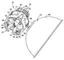
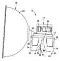
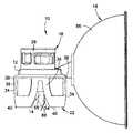
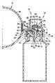
図1~20を参照すると、バイアルアクセス器具10の一実施形態は、ハウジング12、スパイク部材14、および圧力均等化室16を含む。ハウジング12は、第一コネクタ18と第一コネクタ18から反対側に位置付けられた第二コネクタ20を含む。図20に示されるように、第一コネクタ18は、シリンジアダプタ24を介して、シリンジのような第一の容器22に固定されるように構成される。図17に示されるように、第二コネクタ20は、医療用バイアルのような、第二の容器26に固定されるように構成される。他の適切な材料が利用され得るが、ハウジング12は、例えば、射出成形ポリプロピレンのようなポリマー材料から形成され得る。第一コネクタ18は、ハウジング12のネック部28によって形成され、ハウジング12のネック部28は、シリンジアダプタ24の対応する構造とバヨネット式接続を形成する、第一および第二ガイド溝30、32を画定する。第一および第二ガイド溝30は、32は、シリンジアダプタ24の対応する構造を受容し、案内するように構成される。第一コネクタ18は、また、別個に形成され得るけれども、第一コネクタ18は、ハウジング12と一体に形成される。第一コネクタ18として使用され得るコネクタの一つのタイプは、特許文献1に開示されている。特許文献1の全内容は、参照により本明細書に組み込まれる。 Referring to FIGS. 1-20, one embodiment of
第二コネクタ20は、各フック部材34が、近位および遠位端38、40を有するフレキシブルアーム36を含んだ、複数のフック部材34を含む。各アーム36の遠位端40は、図17に示されるような、薬剤を含有する医療用バイアルであり得る、第二の容器26の対応するフランジ44と係合するように構成されたフック突起42を有する。可撓性アーム36は、第二の容器26と係合する際に、半径方向外側に移動し、続いて第二の容器26に、バイアルアクセス器具10を固定するために元の位置に戻るように構成される。第二コネクタ20として使用され得るコネクタの一つのタイプは、参照により本明細書に組み込まれる、特許文献2に開示されている。図7に示されるように、第二コネクタ20は、バイアルアクセス器具10の使用前に、保護キャップ46によって覆われ得る。特に、保護キャップ46は、フック部材34の外部にスナップ嵌めされ、使用者に、スパイク部材14からの保護を提供し、使用前に、ごみがスパイク部材14に入るのを防止する。他の適切な材料が利用され得るけれども、キャップ46は、ポリエチレンなどの高分子材料から作製され得る。 The
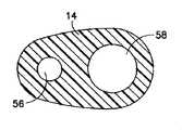
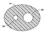
図1~20をなお参照すると、スパイク部材14は、ハウジング12から延び、近位端52および遠位端54を含む。スパイク部材14は、ベントルーメン56とベントルーメン56から離間した流体ルーメン58を画定する。スパイク部材14は、複数のフック部材34に実質的に平行な方向に延び、スパイク部材14の遠位端54に尖った先端60を含む。スパイク部材14は、図19に示されるように、組立時に、第二の容器26を貫通するように構成される。ベントルーメン56および流体ルーメン58の各々は、それぞれ、近位の開口62、64および遠位の開口66、68を含む。図20に示されるように、流体ルーメン58は、バイアルアクセス器具10のハウジング12を通って延びる、シリンジアダプタ24からカニューレ70を受け入れるように構成され、第一および第二の容器22、26の間に、カニューレ70を通って、流体が移送されることを可能にする。流体ルーメン58は、流体ルーメン58の近位開口64と遠位開口68との間で、スパイク部材14の長手方向に延びる。ベントルーメン56および流体ルーメン58の遠位開口66、68は、それぞれ、上端72、74、および、上端72、74から軸方向に離間した下端76、78によって、それぞれ、画定される。 Still referring to FIGS. 1-20,
穿孔可能な膜80が、第一コネクタ18に隣接して配置され、流体ルーメン58の近位開口64を覆う。穿孔可能な膜80は、流体移送中にシリンジアダプタ24のカニューレ70および穿孔可能な膜80との間の液密および気密シールを提供し、漏れや使用者への有害薬剤の曝露を最小限にする。他の適切な材料が利用され得るけれども、貫通可能な膜80は、熱可塑性エラストマー(TPE)から作られ得る。ベントルーメン56は、スパイク部材14の遠位端54から、スパイク部材14の近位端52に、長手方向に延びる。ベントルーメン56は、流体ルーメン58と実質的に平行に整列させられる。ベントルーメン56は、以下に説明されるように、圧力均等化室16と流体連通するように構成される。 A
図7および図8を参照すると、スパイク部材14は、また、スパイク部材14の近位端52に配置されたリング82を含む。リング82は、スパイク部材14から半径方向外向きに延び、スパイク部材14が、医療用バイアルのバイアルストッパーのような、第二の容器62のシール84を貫通するとき、第二の容器26の一部と係合するように構成される。リング82は、バイアルアクセス器具10が、第二の容器26に固定されるとき、バイアルアクセス器具10を安定化することを補助する。特に、リング82は、バイアルアクセス器具10と第二の容器26との間の、ぐらつき、または、接続不良を防止することを補助し得る。リング82は、スパイク部材14の周囲の一部のみに広がり得るが、リング82は、スパイク部材14の全周に延びる。さらに、リング82は、スパイク部材14から離間させられ得、リング82とスパイク部材14との間に環状空間(図示せず)を画定する。 7 and 8,
図1~10を参照すると、他の適切な圧力均等化室、および、材料が、利用され得るけれども、圧力均等化室16は、ポリアミド/ポリプロピレン(PP/PA)のような、可撓性の、不透過性フィルムから作製される、薄く、透明で、拡張可能なブラダー88を有する、半球状または放物線状ディスク86によって画定される。膨張可能なブラダー88は、非拡張状態(図9に示される)と拡張状態(図10に示される)との間で移動可能であり、第二の容器26内における予め定めされた圧力を維持するように作用する。流体移送中に発生する、非拡張状態と拡張状態との間での拡張可能なブラダー88の変位は、以下に、より詳細に説明される。圧力均等化室16は、ベントルーメン56に対し、ほぼ垂直に延びる、圧力室流路90を介してベントルーメン56と流体連通する。圧力室流路90は、ディスク86の略中央に配置される開口92を有する。バリアフィルタ94は、圧力均等化室16と圧力室流路90との間の、圧力室流路90の開口92に配置される。特に、バリアフィルタ94は、圧力室流路90の開口92を覆って、拡張可能なブラダー88と、ディスク86と拡張可能なブラダー88によって画定される容積とに、流体が到達するのを阻止する。バリアフィルタ94は、好ましくは、そこを通って、気体が通過するのを許容するが、液体が通過するのを阻止する、疎水性フィルタである。バリアフィルタ94は、0.1~5μmの間の、好ましくは約3μmの孔径を有する、ポリテトラフルオロエチレン(PTFEまたはテフロン(登録商標))から作製され得る。第二の容器26に、バイアルアクセス器具10を接続することで、圧力均等化室16は、圧力室の流路90およびベントルーメン56を介して、第二の容器26と流体連通するであろう。 1-10,
図17~20を参照すると、バイアルアクセス器具10の作動が、本発明の一実施形態に従って、より詳細に説明されるであろう。バイアルアクセス器具10は、第一コネクタ18を介して、シリンジのような第一の容器22に接続される、シリンジアダプタ24に組み付けられる。さらに、バイアルアクセス器具10は、第二のコネクタ20を介して、第二の容器26に固定される。組み立て後、使用者は、第二の容器26内に流体を導入し、第二の容器26から流体を引き出すことができる。シリンジアダプタ24の一例が、特許文献3に開示される。特許文献3の全内容は参照により本明細書に組み込まれる。図17に示されるように、使用中、バイアルアクセス器具10は、第二コネクタ20を介して、最初に、第二の容器26に固定される。フック部材34は、フック突起42を有する可撓性アーム36が、第二の容器26の対応するフランジ44と係合するので、バイアルアクセス器具10を第二の容器26へしっかりと接続する。バイアルアクセス器具10が、第二の容器26に固定されるとき、スパイク部材14の遠位端54、特に先端60は、第二の容器26の開口を覆って封止する、ストッパーまたはセプタム84を貫通する。シリンジアダプタ24と第一の容器22は、その後、第一コネクタ18を介してバイアルアクセス器具10に固定される。図20に示されるように、シリンジアダプタ24の対応するコネクタは、バイアルアクセス器具10の第一のコネクタ18によって受け入れられ、シリンジアダプタ24を、バイアルアクセス器具10に着脱可能に固定する。シリンジアダプタ24がバイアルアクセス器具10に固定されて、シリンジアダプタ24とバイアルアクセス器具10との間に、漏れのない接続を形成するとき、バイアルアクセス器具10の膜80は、シリンジアダプタ24の膜96に係合する。 17-20, operation of
図20を参照すると、第二の容器26に流体を導入するために、シリンジアダプタ24のカニューレ70は、シリンジアダプタの膜96およびバイアルアクセス器具10の膜80を貫通し、スパイク部材14の流体ルーメン58を通って延びる。希釈剤は、第一の容器22からシリンジアダプタ24を通り、そして、バイアルアクセス器具10を介して第二の容器26に導入され得、第二の容器26内に含まれる凍結乾燥薬剤を再構成する。流体がシリンジアダプタ24のカニューレ70を通して導入されるとき、第二の容器26内の空気が、ベントルーメン56と圧力室流路90を通って圧力均等化室16内に移動させられ、それによって、拡張可能なブラダー88が、図9に示された非拡張状態から図10に示された拡張状態に拡張することをもたらす。バイアルアクセス器具10、第一および第二の容器226、26、および、シリンジアダプタ24は、それから、第二の容器26内で薬剤を再構成するため、図20に示された位置から反転させられ得、その後、任意の適切な装置を使用して、例えば、注射器プランジャの使用を通して、第一の容器22に再構成された薬剤を引き出す。第二の容器26から第一の容器22への流体の移送中に、圧力均等化室16内に以前に移動させられた空気は、圧力室流路90とベントルーメン56を通って、第二の容器26へ流れ、第二の容器26で真空が引き起こされるのを防止する。その時点で、圧力均等化室16のブラダー88は、拡張された状態から非拡張状態に移動することになる。シリンジアダプタ24のカニューレ70は、それから、第二の容器26およびバイアルアクセス器具10から引き抜かれる。シリンジアダプタ24は、次に、適切な装置を介した、例えば、注入セットを通した、患者への輸送または送達の用意ができた薬剤を有する、第一の容器22と共に、バイアルアクセス器具10から取り外され得る。 20, to introduce fluid into the
シリンジアダプタ24のカニューレ70は、スパイク部材14の流体ルーメン58を通って延びているため、カニューレ70は、第二の容器26への各アクセスで、第二の容器26のストッパーまたはセプタム84を穿刺または貫通しなくてもよい。従って、シリンジアダプタ24のカニューレ70による、ストッパー84の複数回の貫通に起因する、引き裂き、磨耗、および切断は、解消され得、ストッパー84から引き裂かれた断片からの、第二の容器26の内容物を汚染する可能性を低減する。バイアルアクセス器具10のスパイク部材14は、第二の容器26の内容物が、ストッパー84のただ一回の貫通で空にさせられることを可能にし、ストッパー84のコアリングの機会を減少させる。 As
第二の容器26のストッパーまたはセプタム84は、様々な設計を有するが、一般的に、半径方向シールを形成するために、全ての範囲で第二の容器26に圧入される。あるストッパー設計は、コーティングされた底面を有する、固体の厚い本体を利用する。ストッパーとして使用されるゴム材料は、実質的に非圧縮性であり得、その結果、ストッパーを貫通する器具の一部は、容器内に、同一容積のストッパーを移動させる必要がある。従来の器具では、そのような移動は、ストッパーのコアリングをもたらし得、それは、ストッパーの除去された部分が、バイアルアダプタを介した空気通路を遮断するか、または、バイアル内に落下し、その内容物を汚染することをもたらす。 The stopper or
再び図1~20を参照すると、スパイク部材14は、本発明の一実施形態によれば、その長手方向の長さに沿って可変の断面を有し、スパイク部材14の貫通部分の容積を最小にする。具体的には、スパイク部材14の外周によって画定される形状は、スパイク部材14の近位端52と流体ルーメン58の遠位開口68との間の位置で、1つの軸に関して対称である。楕円形のスパイク部材14の最小化された体積は、圧縮され、または、排除させられる必要がある、第二の容器26のストッパー84の体積を最小化するのに役立ち、それにより、ストッパー84のコアリングを低減する。 1-20,
図12~16を参照すると、スパイク部材14の外周および断面の形状は楕円形である。シリンジアダプタ24のカニューレ70は、内径D1と外径D2を有する。流体ルーメン58は、好ましくは、D2+(D2-D1)に同等である、D3の内径を有する。ベントルーメン56は、好ましくは、シリンジアダプタ24のカニューレ70の内径D1より小さいか、または、同等である、D4の内径を有する。カニューレ70からの流量は、カニューレ70の内径D1より小さいかまたは同等の大きさの、および、直径D4のベントルーメン56によって維持される。一実施形態において、Y軸に沿った楕円形のスパイク部材14の幅は、図12に示される線15-15において、D3+3T1+D4と同等である。X-軸に沿ったスパイク部材14の幅は、図12に示される線15-15において、D3+2T1と同等である。スパイク部材14の外周は、いかなる外方スプライン、リブ、またはノッチもなく、連続しており、貫通時に、第二の容器26のストッパー84に対してシールし、それによって、外表面が平らでないならば発生し得る、漏れを防止する。 12-16, the outer circumference and cross-sectional shape of
従来の器具において、円形断面を有するニードルは、典型的には、バイアルにアクセスする際に、医療バイアルのような容器のストッパーに対してシールすることによって、十分な漏れ防止を提供する。円形状のスパイクは、しかしながら、あまりにも大きな体積を生み出し、円形状のスパイクによる第二の容器のストッパーの排除に起因するコアリングの問題につながる。スパイク部材14の楕円形の外周と断面は、本発明の一実施例によれば、漏洩保護を提供しながら、スパイク部材14の体積を最小にする。 In conventional instruments, a needle with a circular cross-section typically provides adequate leak protection by sealing against a stopper of a container, such as a medical vial, when accessing the vial. Circular spikes, however, create too much volume and lead to coring problems due to exclusion of the secondary container stopper by the circular spikes. The oval perimeter and cross-section of
図14~17を参照すると、スパイク部材14の近位端52は、スパイク部材14の遠位端54より、より対称的で、より大きい。特に、スパイク部材14の遠位端54に隣接する、スパイク部材14の外周によって画定される形状は、図15に示されるように、一つの軸に沿ってのみ対称である。スパイク部材14の近位端52は、第二の容器26のストッパー84に対してスパイク部材14をシールするために、より対称で、より大きく、シリンジアダプタ24がバイアルアクセス器具10に接続されるとき、または、第一の容器22が回転させられるときに生じ得る、バイアルアクセス器具10が第二の容器26上で回転するときの漏れを防止する。スパイク部材14の遠位端54は、スパイク部材14の体積を最小化し、スパイク部材14によって貫通されるときに、第二の容器26のストッパー84のより大きな排除を防止するために、スパイク部材14の近位部分に比べてより小さい。スパイク部材14は、遠位端54でより薄いが、なお、第二の容器26のストッパー84を貫通するために必要な剛性を有する。図12に示されるように、リング82から遠位に位置するスパイク部材14の部分は、図14に示されるスパイク部材14の大きさから、図15に示されるスパイク部材14の大きさまで、大きさにおいて先細りになる。上述したように、リング82は、スパイク部材14から半径方向外方に延び、リング82から遠位に位置するスパイク部材14の部分よりも大きい外周を有する。従って、リング82の遠位に位置する、スパイク部材14の部分の外周は、ベントおよび流体ルーメン56、58の遠位開口66、68に隣接して位置する、スパイク部材14の部分の外周よりも大きい。図17に示されるように、リング82は、第二の容器26のストッパー84の一部のみを貫通し、第二の容器26に固定されたときに、バイアルアクセス器具10を安定させるように作用する。 14-17,
さらに、従来の器具では、ニードルまたはカニューレのチャネル開口の上端が、流体容器のストッパーに喰い込み得る。本発明の一実施形態による、スパイク部材14は、ベントルーメン56および流体ルーメン58の遠位開口66、68の上端72、74を丸めることにより、この問題を克服する。ベントおよび流体ルーメン56、58の遠位開口66、68の上端72、74(すなわち、後端(heel))の丸め、または、鈍化は、滑らかなベントルーメン56および流体ルーメン58の上端72、74の外側部分をもたらし、スパイク部材14でストッパー84を貫通するとき、医療バイアルのような第二の容器26のストッパー84のコアリングを防止する。コアリングを防止するために、丸みを与えるなど、滑らかな上端72、74を提供するために、他の方法が、利用され得るけれども、ベントルーメン56および流体ルーメン58の遠位開口66、68の上端72、74は、面取りされる。 Furthermore, in conventional instruments, the upper end of the channel opening of the needle or cannula can dig into the stopper of the fluid container. The
図18を参照すると、ベントルーメン56および流体ルーメン58の、遠位開口66、68は、切り欠き部C1、C2によって形成され、ベントルーメン56および流体ルーメン58の上端72、74が、滑らかであることを可能にする。ベントルーメン56および流体ルーメン58の遠位開口66、68は、角度をつけて設けられ、スパイク部材14の長手方向に延びる。切り欠き部C1、C2のエッジの半径Rは、少なくとも0.05mm~0.1mm以上であり得る。ある実施形態において、流体ルーメン58とベントルーメン56の長さは、市販のストッパーの大部分と共に利用されるよう、第二の容器26に使用される最も厚いストッパーまたはセプタム84に適合するように最適化される。 18,
図17を参照すると、ベントルーメン56と流体ルーメン58の遠位開口66、68の、スパイク部材14の長手方向軸に沿った、フック部材34に関連した配置は、ストッパー84の底部に関連して、遠位開口66、68の配置を決定する。例示的な実施形態において約0.64mmであり得る、距離Lは、スパイク部材14の長手方向軸に沿って、フック部材34のフック突起42の平坦な表面と、流体ルーメン58の近位開口64を隔てている。例示的な実施形態において約1.67mmであり得る距離hは、スパイク部材14の長手方向軸に沿って、流体ルーメン58の遠位開口68とベントルーメン56の近位開口62を隔てている。 17, the placement of the
図17および図19を参照すると、スパイク部材14が、より薄いスパイクによって生成されるであろう、図19に示される、ストッパー84とスパイク部材14との間のデッドボリュームVを満たすため、比較的大きな体積のスパイク部材14が有利である。 17 and 19, in order to fill the dead volume V between
図11を参照すると、スパイク部材14の遠位端の角度Aと、長手方向軸に沿ったベントルーメン56と流体ルーメンの遠位開口66、68の長さL1との関係は、L1=D6/tan(A/2)=D5/tan(a/2)で定義され、D6は、ベントルーメン56の直径、D5は、流体ルーメン58の直径、角度aは、流体ルーメン58の切り欠き角度である。一実施形態では、角度Aおよび切り欠き角度は、より小さい大きさであり、または、第二の容器26のストッパー84のより容易な貫通のために最適とされる。一実施形態において、ストッパー84の貫通の間、漏れを防止するために、スパイク部材14の遠位開口66、68の長さL1は、ISO 8362-2:2008による最も薄いストッパーの厚さよりも、スパイク部材14の長手方向において短い。遠位開口66、68が、ストッパー84の厚さよりも長いと、貫通の間、暫時、オープンチャネルが存在し、第二の容器26の加圧された内容物によって、オープンチャネルを介して、漏洩が生ずる。 11, the relationship between the angle A of the distal end of the
図17を参照すると、例示的な実施形態において、ベントルーメン56の先端開口66は、可能な限り、スパイク部材14の遠位端54の近くに(すなわち、先端60の近くに)、可能な限り、流体ルーメン58の遠位開口68から離れて配置され、第二の容器26から液体を引き出す際に、流体ルーメン58への空気流入のリスクを最小限にする。 17, in an exemplary embodiment, the tip opening 66 of the
図21を参照すると、バイアルアクセス器具100のさらなる実施形態が示される。図21に示されたバイアルアクセス器具100は、本実施形態のバイアルアクセス器具100が、スパイク部材14の外面に塗布された潤滑剤被膜102を含むことを除いて、上述の図1~図20に示されたバイアルアクセス器具10と同一である。潤滑剤被膜102は、第二の容器26のストッパー84への、スパイク部材14の貫通によって生じる摩擦を低減する。他の適切な潤滑剤被覆が利用され得るが、潤滑剤被膜102は、シリコーン系であり得る。例示的な実施形態において、図21にクロスハッチングで示される、潤滑剤被膜102は、スパイク部材14の先端60の近くで、流体ルーメン58とベントルーメン56の遠位開口66、68の上を覆って適用される。被膜102を塗布するための他の適切なプロセスが利用され得るが、潤滑剤被膜102は、修正されたトランスファパッド(タンポン)印刷法により塗布され得、スパイク部材14の表面の約70%をカバーするために、時間をかけて移動する。 Referring to FIG. 21, a further embodiment of
本明細書に開示される例示的なバイアルアクセス器具10、100で使用される個々の構成要素は、当技術分野で知られている、既存の設計および構成要素に基づき得る。本明細書中に参考として援用される以下の付加的な米国特許文献は、本発明の実施において使用され得る例示的な構成要素およびサブシステムを開示する。特許文献4、特許文献5、特許文献6、特許文献7、特許文献8、特許文献9、および、特許文献10。 The individual components used in the exemplary
本発明のある好ましい実施形態を参照して、本発明のある例示的な実施形態が図示され、本明細書中で説明されたが、形態および細部における様々な変更が、本発明の精神および範囲から逸脱することなく、その中でなされ得ることが、当業者に理解されるであろう。 While certain exemplary embodiments of the invention have been illustrated and described herein with reference to certain preferred embodiments of the invention, various changes in form and detail may be made without departing from the spirit and scope of the invention. It will be understood by those skilled in the art that things can be done therein without departing from.
Claims (16)
Translated fromJapanese第一および第二のコネクタを有するハウジングであって、上記第一のコネクタは、第一の容器に固定されるように構成され、上記第二のコネクタは、第二の容器に固定されるように構成された、上記ハウジングと、
上記ハウジングから延び、近位端および遠位端を有するスパイク部材であって、該スパイク部材は、ベントルーメンと該ベントルーメンから離間した流体ルーメンを画定しており、上記ベントルーメンと上記流体ルーメンのそれぞれは、遠位開口を有し、上記ベントルーメンと上記流体ルーメンの上記遠位開口は、それぞれ、上端と、該上端から上記スパイク部材の長手方向軸に沿って延びる方向に離間した下端によって画定され、上記流体ルーメンの上記下端は、上記スパイク部材の長手方向軸に沿って延びる方向において、上記ベントルーメンの上記遠位開口の上方に位置づけられ、上記スパイク部材は、該スパイク部材から半径方向外向きに延びるリングを含み、該リングは、上記スパイク部材で第二の容器のストッパーを貫通する際、上記ストッパーの一部を貫通し、上記ストッパーの一部と係合するように構成される、上記スパイク部材を含むことを特徴とするバイアルアクセス器具。A vial access device, the vial access device comprising:
A housing having first and second connectors, wherein the first connector is configured to be secured to a first container and the second connector is configured to be secured to a second container the housing configured to:
a spike member extending from the housing and having a proximal end and a distal end, the spike member defining a vent lumen and a fluid lumen spaced from the vent lumen; Each has a distal opening, and the distal openings of the vent and fluid lumens are each defined by an upper end and a lower end spaced apart from the upper end ina direction extending along the longitudinal axis of the spike member. and the lower end of the fluid lumen is positioned above the distal opening of the vent lumen in a direction extending along the longitudinal axis of the spike member, and the spike member extends radially outward from the spike member. a ring extending in the opposite direction, the ring configured to penetrate a portion of the stopper and engage a portion of the stopper when the spike member penetratesthe stopper of the second container ; A vial access device comprising the spike member described above.
Applications Claiming Priority (2)
| Application Number | Priority Date | Filing Date | Title |
|---|---|---|---|
| US201261671567P | 2012-07-13 | 2012-07-13 | |
| US61/671,567 | 2012-07-13 |
Related Parent Applications (1)
| Application Number | Title | Priority Date | Filing Date |
|---|---|---|---|
| JP2017150786ADivisionJP6839050B2 (en) | 2012-07-13 | 2017-08-03 | Medical vial access device with pressure equalization and closed drug transfer system |
Publications (2)
| Publication Number | Publication Date |
|---|---|
| JP2019195664A JP2019195664A (en) | 2019-11-14 |
| JP7132185B2true JP7132185B2 (en) | 2022-09-06 |
Family
ID=48790465
Family Applications (3)
| Application Number | Title | Priority Date | Filing Date |
|---|---|---|---|
| JP2015521024AActiveJP6189951B2 (en) | 2012-07-13 | 2013-07-12 | Medical vial access device with pressure equalization and closed drug delivery system |
| JP2017150786AActiveJP6839050B2 (en) | 2012-07-13 | 2017-08-03 | Medical vial access device with pressure equalization and closed drug transfer system |
| JP2019130332AActiveJP7132185B2 (en) | 2012-07-13 | 2019-07-12 | Medical vial access device with pressure equalization and closed drug delivery system |
Family Applications Before (2)
| Application Number | Title | Priority Date | Filing Date |
|---|---|---|---|
| JP2015521024AActiveJP6189951B2 (en) | 2012-07-13 | 2013-07-12 | Medical vial access device with pressure equalization and closed drug delivery system |
| JP2017150786AActiveJP6839050B2 (en) | 2012-07-13 | 2017-08-03 | Medical vial access device with pressure equalization and closed drug transfer system |
Country Status (8)
| Country | Link |
|---|---|
| US (2) | US9089474B2 (en) |
| EP (2) | EP2872101B1 (en) |
| JP (3) | JP6189951B2 (en) |
| CN (3) | CN106974829B (en) |
| CA (2) | CA2878940C (en) |
| ES (2) | ES2596519T3 (en) |
| IL (2) | IL236635B (en) |
| WO (1) | WO2014009556A2 (en) |
Families Citing this family (55)
| Publication number | Priority date | Publication date | Assignee | Title |
|---|---|---|---|---|
| US7547300B2 (en) | 2006-04-12 | 2009-06-16 | Icu Medical, Inc. | Vial adaptor for regulating pressure |
| US7883499B2 (en) | 2007-03-09 | 2011-02-08 | Icu Medical, Inc. | Vial adaptors and vials for regulating pressure |
| WO2010022095A1 (en) | 2008-08-20 | 2010-02-25 | Icu Medical, Inc. | Anti-reflux vial adaptors |
| ES3004613T3 (en) | 2009-07-29 | 2025-03-12 | Icu Medical Inc | Fluid transfer devices |
| US8366685B2 (en) | 2011-04-26 | 2013-02-05 | Creative Vascular, Llc | Systems and methods for phlebotomy through a peripheral IV catheter |
| US10076272B2 (en) | 2011-04-26 | 2018-09-18 | Velano Vascular, Inc. | Systems and methods for phlebotomy through a peripheral IV catheter |
| CA3176437A1 (en) | 2011-08-18 | 2013-02-21 | Icu Medical, Inc. | Pressure-regulating vial adaptors |
| KR102145639B1 (en) | 2011-12-22 | 2020-08-19 | 아이씨유 메디칼 인코퍼레이티드 | Fluid transfer devices and methods of use |
| DK2802377T3 (en) | 2012-01-13 | 2017-03-20 | Icu Medical Inc | Pressure regulating bottle adapter and method |
| AU2013204180B2 (en) | 2012-03-22 | 2016-07-21 | Icu Medical, Inc. | Pressure-regulating vial adaptors |
| ES2596519T3 (en)* | 2012-07-13 | 2017-01-10 | Becton, Dickinson And Company Ltd. | Access device to a medical vial with pressure equalization system and closed medication transfer and method of use thereof |
| USD717947S1 (en)* | 2012-07-13 | 2014-11-18 | Carmel Pharma Ab | Spike for medical vial access device |
| US9089475B2 (en) | 2013-01-23 | 2015-07-28 | Icu Medical, Inc. | Pressure-regulating vial adaptors |
| ES2739291T3 (en) | 2013-01-23 | 2020-01-30 | Icu Medical Inc | Pressure regulation vial adapters |
| WO2014188407A1 (en)* | 2013-05-20 | 2014-11-27 | Vapo-Q Closed Systems Ltd. | Vial and syringe adaptors and systems using same |
| CA3179530A1 (en) | 2013-07-19 | 2015-01-22 | Icu Medical, Inc. | Pressure-regulating fluid transfer systems and methods |
| ES2805051T3 (en) | 2013-11-25 | 2021-02-10 | Icu Medical Inc | Procedures and system for filling I.V. bags with therapeutic liquid |
| EP2921153A1 (en)* | 2014-03-21 | 2015-09-23 | 3M Innovative Properties Company | An adapter for coupling two syringes and a system of an adapter and two syringes |
| WO2015195844A1 (en) | 2014-06-20 | 2015-12-23 | Icu Medical, Inc. | Pressure-regulating vial adaptors |
| DE102014226702B4 (en)* | 2014-12-19 | 2019-02-21 | B. Braun Melsungen Ag | Connection unit for a medical fluid system |
| DE102015201288B4 (en)* | 2015-01-26 | 2017-01-05 | Bayer Pharma AG | Hollow-needle assembly |
| US10413662B2 (en) | 2015-05-14 | 2019-09-17 | Carefusion 303, Inc. | Priming apparatus and method |
| BR112017026574B1 (en) | 2015-06-12 | 2022-04-26 | Becton Dickinson and Company Limited | Syringe adapter with rotating connector |
| EP4534065A3 (en) | 2015-12-04 | 2025-06-04 | ICU Medical, Inc. | Systems methods and components for transferring medical fluids |
| SG10202013249PA (en)* | 2015-12-24 | 2021-02-25 | Celgene Quanticel Research Inc | Bromodomain and extra-terminal protein inhibitor combination therapy |
| EP3397231B1 (en) | 2016-01-29 | 2022-03-02 | ICU Medical, Inc. | Pressure-regulating vial adaptors |
| IL245803A0 (en)* | 2016-05-24 | 2016-08-31 | West Pharma Services Il Ltd | Dual vial adapter assemblages including vented drug vial adapter and vented liquid vial adapter |
| USD851745S1 (en) | 2016-07-19 | 2019-06-18 | Icu Medical, Inc. | Medical fluid transfer system |
| EP3487468B1 (en) | 2016-07-25 | 2025-10-01 | ICU Medical, Inc. | Systems and components for trapping air bubbles in medical fluid transfer modules and systems |
| CA3037577A1 (en) | 2016-09-30 | 2018-04-05 | Icu Medical, Inc. | Pressure-regulating vial access devices and methods |
| AU2018210833B2 (en)* | 2017-01-17 | 2023-05-04 | Becton Dickinson and Company Limited | Syringe adapter |
| CA3050433A1 (en)* | 2017-01-17 | 2018-07-26 | Becton Dickinson and Company Limited | Syringe adapter with cap |
| DE102017201755A1 (en)* | 2017-02-03 | 2018-08-09 | B. Braun Melsungen Ag | Penetration part for a medical infusion system, drip chamber and infusion system |
| KR102573751B1 (en) | 2017-03-21 | 2023-09-04 | 벨라노 바스큘라, 인크. | Devices and methods for fluid delivery through a deployed peripheral intravenous catheter |
| US10773056B2 (en) | 2017-03-21 | 2020-09-15 | Velano Vascular, Inc. | Systems and methods for controlling catheter device size |
| JP2020532340A (en)* | 2017-07-20 | 2020-11-12 | ヤンセン バイオテツク,インコーポレーテツド | Drug mixer |
| CN111526855B (en) | 2018-01-04 | 2024-06-07 | 爱康医学农业合作协会有限公司 | Vial adapter assembly for closed fluid delivery system |
| US11413216B2 (en) | 2018-03-20 | 2022-08-16 | Becton Dickinson and Company Limited | Connection arrangement for closed system transfer of fluids |
| USD873996S1 (en) | 2018-04-04 | 2020-01-28 | Becton Dickinson and Company Limited | Medical syringe adapter |
| USD908872S1 (en) | 2018-04-04 | 2021-01-26 | Becton Dickinson and Company Limited | Medical vial access device |
| USD877900S1 (en) | 2018-04-04 | 2020-03-10 | Becton Dickinson and Company Limited | Medical infusion adapter |
| USD888945S1 (en) | 2018-04-04 | 2020-06-30 | Becton Dickinson and Company Limited | Medical connector |
| JP7171037B2 (en)* | 2018-04-19 | 2022-11-15 | 内外化成株式会社 | Transfusion member and manufacturing method thereof |
| US11224555B2 (en) | 2018-04-23 | 2022-01-18 | Hospira, Inc. | Access and vapor containment system for a drug vial and method of making and using same |
| ES2986346T3 (en) | 2018-10-05 | 2024-11-11 | Lts Device Tech Ltd | Activation sequence |
| EP3718528A1 (en)* | 2019-04-01 | 2020-10-07 | Simplivia Healthcare Ltd. | Vial adaptor with air resistor |
| EP4603074A3 (en)* | 2019-07-03 | 2025-10-15 | Becton, Dickinson and Company | Medical device, medical device assembly including the same, and method of reconstitution of a pharmaceutical composition |
| IL268368B2 (en)* | 2019-07-30 | 2023-11-01 | Equashield Medical Ltd | Ingredients for open systems of liquid drug delivery and a robotic system that utilizes them |
| CN119185741A (en) | 2019-08-20 | 2024-12-27 | 威蓝诺血管股份有限公司 | Fluid delivery device with elongate conduit and method of use thereof |
| DE102019217908A1 (en)* | 2019-11-20 | 2021-05-20 | B. Braun Melsungen Aktiengesellschaft | Medical fluid transfer device |
| CA3166759A1 (en)* | 2020-02-05 | 2021-08-12 | Alicia MALBIN | System and method for priming an intravenous line |
| US11590057B2 (en) | 2020-04-03 | 2023-02-28 | Icu Medical, Inc. | Systems, methods, and components for transferring medical fluids |
| US20230248899A1 (en)* | 2020-06-25 | 2023-08-10 | Bard Peripheral Vascular, Inc. | Medical Delivery Assembly With Multi-Port Needle |
| MX2023006170A (en) | 2020-11-26 | 2023-06-08 | Avia Vascular Llc | BLOOD COLLECTION DEVICES, SYSTEMS AND METHODS. |
| WO2025047538A1 (en)* | 2023-08-25 | 2025-03-06 | テルモ株式会社 | Vial adapter |
Citations (2)
| Publication number | Priority date | Publication date | Assignee | Title |
|---|---|---|---|---|
| JP2002336355A (en) | 2001-05-11 | 2002-11-26 | Mitsubishi Pencil Co Ltd | Syringe needle |
| WO2011068190A1 (en) | 2009-12-04 | 2011-06-09 | テルモ株式会社 | Vial adapter |
Family Cites Families (47)
| Publication number | Priority date | Publication date | Assignee | Title |
|---|---|---|---|---|
| FR1600153A (en)* | 1968-12-31 | 1970-07-20 | ||
| US3980083A (en)* | 1975-02-13 | 1976-09-14 | Illinois Tool Works Inc. | Medicament infusor unit |
| IT1167051B (en)* | 1979-05-02 | 1987-05-06 | Sigma Tau Ind Farmaceuti | CONTAINER AND DOSER MIXER COMPLEX IN PARTICULAR FOR MEDICINAL SOLUTIONS |
| US4296786A (en)* | 1979-09-28 | 1981-10-27 | The West Company | Transfer device for use in mixing a primary solution and a secondary or additive substance |
| US4335718A (en)* | 1980-10-02 | 1982-06-22 | Becton, Dickinson And Company | Needle cannula |
| US4834744A (en) | 1987-11-04 | 1989-05-30 | Critikon, Inc. | Spike for parenteral solution container |
| DE3818682A1 (en)* | 1988-06-01 | 1989-12-21 | Deussen Stella Kg | AMPOULE |
| US5304163A (en)* | 1990-01-29 | 1994-04-19 | Baxter International Inc. | Integral reconstitution device |
| DE9002924U1 (en)* | 1990-03-15 | 1990-05-17 | Bayer Ag, 5090 Leverkusen | Hollow mandrel made of plastic |
| US5242432A (en)* | 1991-09-26 | 1993-09-07 | Ivac | Needleless adapter |
| US5474544A (en)* | 1994-05-25 | 1995-12-12 | Lynn; Lawrence A. | Luer-receiving medical valve |
| SE509950C2 (en) | 1995-05-02 | 1999-03-29 | Carmel Pharma Ab | Device for the administration of toxic liquid |
| US5752942A (en)* | 1996-06-20 | 1998-05-19 | Becton Dickinson And Company | Five beveled point geometry for a hypodermic needle |
| US7468055B2 (en)* | 1996-06-20 | 2008-12-23 | Becton Dickinson And Company | Multi-beveled point needle and syringe having a multi-beveled point needle |
| PT952868E (en)* | 1996-11-18 | 2004-08-31 | Nypro Inc | VALVE CONICA-LUER LAVAVEL |
| WO1999061093A1 (en)* | 1998-05-29 | 1999-12-02 | Lynn Lawrence A | Luer receiver and method for fluid transfer |
| US20050137566A1 (en)* | 2003-12-23 | 2005-06-23 | Fowles Thomas A. | Sliding reconstitution device for a diluent container |
| US6832994B2 (en) | 2000-01-24 | 2004-12-21 | Bracco Diagnostics Inc. | Table top drug dispensing vial access adapter |
| US6544246B1 (en)* | 2000-01-24 | 2003-04-08 | Bracco Diagnostics, Inc. | Vial access adapter and vial combination |
| US6343629B1 (en) | 2000-06-02 | 2002-02-05 | Carmel Pharma Ab | Coupling device for coupling a vial connector to a drug vial |
| FR2821827B1 (en)* | 2001-03-07 | 2003-06-13 | Biodome | CONNECTION DEVICE BETWEEN A CONTAINER AND A CONTAINER AND READY-TO-USE ASSEMBLY COMPRISING SUCH A DEVICE |
| US6715520B2 (en) | 2001-10-11 | 2004-04-06 | Carmel Pharma Ab | Method and assembly for fluid transfer |
| JP4331675B2 (en)* | 2002-05-16 | 2009-09-16 | スコット・ラボラトリーズ・インコーポレイテッド | Drug container insertion mechanism and method |
| US7056308B2 (en)* | 2002-10-04 | 2006-06-06 | Dsu Medical Corporation | Medical device with elastomeric penetrable wall and inner seal |
| US8377039B2 (en)* | 2002-10-04 | 2013-02-19 | Nxstage Medical, Inc. | Injection site for male luer or other tubular connector |
| US7025744B2 (en)* | 2002-10-04 | 2006-04-11 | Dsu Medical Corporation | Injection site for male luer or other tubular connector |
| DK1454609T3 (en)* | 2003-03-05 | 2013-02-11 | Csl Behring Gmbh | Transmission facility |
| US7651482B2 (en)* | 2005-02-04 | 2010-01-26 | Boston Scientific Scimed, Inc. | Non-coring needles and methods of manufacturing same |
| US8540686B2 (en)* | 2005-03-02 | 2013-09-24 | Covidien Ag | Blunt tip vial access cannula |
| AU2006348410B2 (en)* | 2005-11-07 | 2011-12-15 | Industrie Borla S.P.A. | Vented safe handling vial adapter |
| US7981101B2 (en)* | 2005-12-30 | 2011-07-19 | Carefusion 303, Inc. | Medical vial adapter with reduced diameter cannula and enlarged vent lumen |
| CN101478929A (en)* | 2006-05-04 | 2009-07-08 | 伯尔拉工业有限公司 | Vented infusion access device |
| US20080107564A1 (en)* | 2006-07-20 | 2008-05-08 | Shmuel Sternberg | Medical fluid access site with antiseptic indicator |
| US8167863B2 (en)* | 2006-10-16 | 2012-05-01 | Carefusion 303, Inc. | Vented vial adapter with filter for aerosol retention |
| EP2101711A1 (en)* | 2006-11-30 | 2009-09-23 | Medi-Physics, Inc. | Dual-lumen needle with an elongate notch opening |
| US7900659B2 (en)* | 2006-12-19 | 2011-03-08 | Carefusion 303, Inc. | Pressure equalizing device for vial access |
| DE102007061346A1 (en)* | 2007-12-17 | 2009-06-18 | Bayer Schering Pharma Aktiengesellschaft | Spike with two thorns |
| CA2715894C (en)* | 2008-02-18 | 2014-10-14 | Icu Medical, Inc. | Vial adaptor |
| US8075550B2 (en) | 2008-07-01 | 2011-12-13 | Carmel Pharma Ab | Piercing member protection device |
| CN201290932Y (en)* | 2008-11-19 | 2009-08-19 | 崔照有 | Novel medical dispensation needle |
| WO2010069359A1 (en) | 2008-12-15 | 2010-06-24 | Carmel Pharma Ab | Connector device |
| US8523838B2 (en)* | 2008-12-15 | 2013-09-03 | Carmel Pharma Ab | Connector device |
| USD637713S1 (en) | 2009-11-20 | 2011-05-10 | Carmel Pharma Ab | Medical device adaptor |
| US8480646B2 (en) | 2009-11-20 | 2013-07-09 | Carmel Pharma Ab | Medical device connector |
| NZ606732A (en)* | 2010-08-25 | 2015-01-30 | Baxter Healthcare Sa | Assembly to facilitate user reconstitution |
| US8945087B2 (en)* | 2011-09-30 | 2015-02-03 | Covidien Lp | Pre-pierced IV access port |
| ES2596519T3 (en)* | 2012-07-13 | 2017-01-10 | Becton, Dickinson And Company Ltd. | Access device to a medical vial with pressure equalization system and closed medication transfer and method of use thereof |
- 2013
- 2013-07-12ESES13736914.6Tpatent/ES2596519T3/enactiveActive
- 2013-07-12CACA2878940Apatent/CA2878940C/enactiveActive
- 2013-07-12USUS13/940,809patent/US9089474B2/enactiveActive
- 2013-07-12CACA2986962Apatent/CA2986962C/enactiveActive
- 2013-07-12WOPCT/EP2013/064847patent/WO2014009556A2/enactiveApplication Filing
- 2013-07-12EPEP13736914.6Apatent/EP2872101B1/enactiveActive
- 2013-07-12JPJP2015521024Apatent/JP6189951B2/enactiveActive
- 2013-07-12EPEP16173034.6Apatent/EP3081204B1/enactiveActive
- 2013-07-12ESES16173034Tpatent/ES2740107T3/enactiveActive
- 2013-07-15CNCN201611159802.2Apatent/CN106974829B/enactiveActive
- 2013-07-15CNCN201320419529.8Upatent/CN203469038U/ennot_activeExpired - Lifetime
- 2013-07-15CNCN201310295726.8Apatent/CN103585014B/enactiveActive
- 2015
- 2015-01-11ILIL23663515Apatent/IL236635B/enactiveIP Right Grant
- 2015-07-07USUS14/793,039patent/US10434034B2/enactiveActive
- 2017
- 2017-08-03JPJP2017150786Apatent/JP6839050B2/enactiveActive
- 2019
- 2019-07-12JPJP2019130332Apatent/JP7132185B2/enactiveActive
- 2019-09-19ILIL269469Apatent/IL269469B/enactiveIP Right Grant
Patent Citations (2)
| Publication number | Priority date | Publication date | Assignee | Title |
|---|---|---|---|---|
| JP2002336355A (en) | 2001-05-11 | 2002-11-26 | Mitsubishi Pencil Co Ltd | Syringe needle |
| WO2011068190A1 (en) | 2009-12-04 | 2011-06-09 | テルモ株式会社 | Vial adapter |
Also Published As
| Publication number | Publication date |
|---|---|
| CA2878940A1 (en) | 2014-01-16 |
| CN106974829B (en) | 2020-04-10 |
| IL269469B (en) | 2020-07-30 |
| CN203469038U (en) | 2014-03-12 |
| EP3081204A1 (en) | 2016-10-19 |
| EP2872101B1 (en) | 2016-09-07 |
| CA2986962A1 (en) | 2014-01-16 |
| US9089474B2 (en) | 2015-07-28 |
| JP2015525629A (en) | 2015-09-07 |
| JP6189951B2 (en) | 2017-08-30 |
| CN103585014B (en) | 2017-03-01 |
| WO2014009556A2 (en) | 2014-01-16 |
| CN103585014A (en) | 2014-02-19 |
| WO2014009556A3 (en) | 2014-07-17 |
| JP2017192839A (en) | 2017-10-26 |
| IL269469A (en) | 2019-11-28 |
| JP2019195664A (en) | 2019-11-14 |
| IL236635B (en) | 2019-10-31 |
| ES2740107T3 (en) | 2020-02-05 |
| JP6839050B2 (en) | 2021-03-03 |
| CA2986962C (en) | 2020-04-14 |
| CA2878940C (en) | 2018-01-16 |
| CN106974829A (en) | 2017-07-25 |
| US20140014210A1 (en) | 2014-01-16 |
| EP3081204B1 (en) | 2019-05-08 |
| EP2872101A2 (en) | 2015-05-20 |
| US20150305981A1 (en) | 2015-10-29 |
| IL236635A0 (en) | 2015-02-26 |
| US10434034B2 (en) | 2019-10-08 |
| ES2596519T3 (en) | 2017-01-10 |
Similar Documents
| Publication | Publication Date | Title |
|---|---|---|
| JP7132185B2 (en) | Medical vial access device with pressure equalization and closed drug delivery system | |
| US11690788B2 (en) | System for closed transfer of fluids | |
| US20210331824A1 (en) | Piercing Member for Container Access Device | |
| EP2968066B1 (en) | Seal system for cannula | |
| KR20040111430A (en) | Sliding reconstitution device for a diluent container | |
| US12280009B2 (en) | Protector housing plastic spike with flash intended for DVO last drop extraction | |
| US9737700B2 (en) | Flexible multi-use container, system and method of manufacture | |
| EP3049048B1 (en) | Piercing member for container access device |
Legal Events
| Date | Code | Title | Description |
|---|---|---|---|
| A621 | Written request for application examination | Free format text:JAPANESE INTERMEDIATE CODE: A621 Effective date:20190730 | |
| A131 | Notification of reasons for refusal | Free format text:JAPANESE INTERMEDIATE CODE: A131 Effective date:20200929 | |
| A521 | Request for written amendment filed | Free format text:JAPANESE INTERMEDIATE CODE: A523 Effective date:20201211 | |
| A02 | Decision of refusal | Free format text:JAPANESE INTERMEDIATE CODE: A02 Effective date:20210518 | |
| A521 | Request for written amendment filed | Free format text:JAPANESE INTERMEDIATE CODE: A523 Effective date:20210819 | |
| C60 | Trial request (containing other claim documents, opposition documents) | Free format text:JAPANESE INTERMEDIATE CODE: C60 Effective date:20210819 | |
| A911 | Transfer to examiner for re-examination before appeal (zenchi) | Free format text:JAPANESE INTERMEDIATE CODE: A911 Effective date:20210827 | |
| C21 | Notice of transfer of a case for reconsideration by examiners before appeal proceedings | Free format text:JAPANESE INTERMEDIATE CODE: C21 Effective date:20210831 | |
| A912 | Re-examination (zenchi) completed and case transferred to appeal board | Free format text:JAPANESE INTERMEDIATE CODE: A912 Effective date:20211015 | |
| C211 | Notice of termination of reconsideration by examiners before appeal proceedings | Free format text:JAPANESE INTERMEDIATE CODE: C211 Effective date:20211019 | |
| C22 | Notice of designation (change) of administrative judge | Free format text:JAPANESE INTERMEDIATE CODE: C22 Effective date:20220111 | |
| C22 | Notice of designation (change) of administrative judge | Free format text:JAPANESE INTERMEDIATE CODE: C22 Effective date:20220222 | |
| C13 | Notice of reasons for refusal | Free format text:JAPANESE INTERMEDIATE CODE: C13 Effective date:20220315 | |
| C22 | Notice of designation (change) of administrative judge | Free format text:JAPANESE INTERMEDIATE CODE: C22 Effective date:20220412 | |
| C22 | Notice of designation (change) of administrative judge | Free format text:JAPANESE INTERMEDIATE CODE: C22 Effective date:20220531 | |
| A521 | Request for written amendment filed | Free format text:JAPANESE INTERMEDIATE CODE: A523 Effective date:20220615 | |
| C23 | Notice of termination of proceedings | Free format text:JAPANESE INTERMEDIATE CODE: C23 Effective date:20220628 | |
| C03 | Trial/appeal decision taken | Free format text:JAPANESE INTERMEDIATE CODE: C03 Effective date:20220726 | |
| C30A | Notification sent | Free format text:JAPANESE INTERMEDIATE CODE: C3012 Effective date:20220726 | |
| A61 | First payment of annual fees (during grant procedure) | Free format text:JAPANESE INTERMEDIATE CODE: A61 Effective date:20220825 | |
| R150 | Certificate of patent or registration of utility model | Ref document number:7132185 Country of ref document:JP Free format text:JAPANESE INTERMEDIATE CODE: R150 |