JP7130627B2 - stapler beam structure - Google Patents
stapler beam structureDownload PDFInfo
- Publication number
- JP7130627B2 JP7130627B2JP2019513355AJP2019513355AJP7130627B2JP 7130627 B2JP7130627 B2JP 7130627B2JP 2019513355 AJP2019513355 AJP 2019513355AJP 2019513355 AJP2019513355 AJP 2019513355AJP 7130627 B2JP7130627 B2JP 7130627B2
- Authority
- JP
- Japan
- Prior art keywords
- assembly
- beam member
- surgical device
- wrist
- actuation
- Prior art date
- Legal status (The legal status is an assumption and is not a legal conclusion. Google has not performed a legal analysis and makes no representation as to the accuracy of the status listed.)
- Active
Links
Images


Classifications
- A—HUMAN NECESSITIES
- A61—MEDICAL OR VETERINARY SCIENCE; HYGIENE
- A61B—DIAGNOSIS; SURGERY; IDENTIFICATION
- A61B34/00—Computer-aided surgery; Manipulators or robots specially adapted for use in surgery
- A61B34/30—Surgical robots
- A61B34/35—Surgical robots for telesurgery
- A—HUMAN NECESSITIES
- A61—MEDICAL OR VETERINARY SCIENCE; HYGIENE
- A61B—DIAGNOSIS; SURGERY; IDENTIFICATION
- A61B17/00—Surgical instruments, devices or methods
- A61B17/068—Surgical staplers, e.g. containing multiple staples or clamps
- A61B17/072—Surgical staplers, e.g. containing multiple staples or clamps for applying a row of staples in a single action, e.g. the staples being applied simultaneously
- A61B17/07207—Surgical staplers, e.g. containing multiple staples or clamps for applying a row of staples in a single action, e.g. the staples being applied simultaneously the staples being applied sequentially
- A—HUMAN NECESSITIES
- A61—MEDICAL OR VETERINARY SCIENCE; HYGIENE
- A61B—DIAGNOSIS; SURGERY; IDENTIFICATION
- A61B17/00—Surgical instruments, devices or methods
- A61B17/00234—Surgical instruments, devices or methods for minimally invasive surgery
- A61B2017/00292—Surgical instruments, devices or methods for minimally invasive surgery mounted on or guided by flexible, e.g. catheter-like, means
- A61B2017/003—Steerable
- A61B2017/00305—Constructional details of the flexible means
- A61B2017/00309—Cut-outs or slits
- A—HUMAN NECESSITIES
- A61—MEDICAL OR VETERINARY SCIENCE; HYGIENE
- A61B—DIAGNOSIS; SURGERY; IDENTIFICATION
- A61B17/00—Surgical instruments, devices or methods
- A61B2017/00367—Details of actuation of instruments, e.g. relations between pushing buttons, or the like, and activation of the tool, working tip, or the like
- A—HUMAN NECESSITIES
- A61—MEDICAL OR VETERINARY SCIENCE; HYGIENE
- A61B—DIAGNOSIS; SURGERY; IDENTIFICATION
- A61B17/00—Surgical instruments, devices or methods
- A61B2017/00477—Coupling
- A—HUMAN NECESSITIES
- A61—MEDICAL OR VETERINARY SCIENCE; HYGIENE
- A61B—DIAGNOSIS; SURGERY; IDENTIFICATION
- A61B17/00—Surgical instruments, devices or methods
- A61B2017/00831—Material properties
- A61B2017/00867—Material properties shape memory effect
- A—HUMAN NECESSITIES
- A61—MEDICAL OR VETERINARY SCIENCE; HYGIENE
- A61B—DIAGNOSIS; SURGERY; IDENTIFICATION
- A61B17/00—Surgical instruments, devices or methods
- A61B17/068—Surgical staplers, e.g. containing multiple staples or clamps
- A61B17/072—Surgical staplers, e.g. containing multiple staples or clamps for applying a row of staples in a single action, e.g. the staples being applied simultaneously
- A61B2017/07214—Stapler heads
- A61B2017/07271—Stapler heads characterised by its cartridge
- A—HUMAN NECESSITIES
- A61—MEDICAL OR VETERINARY SCIENCE; HYGIENE
- A61B—DIAGNOSIS; SURGERY; IDENTIFICATION
- A61B17/00—Surgical instruments, devices or methods
- A61B17/068—Surgical staplers, e.g. containing multiple staples or clamps
- A61B17/072—Surgical staplers, e.g. containing multiple staples or clamps for applying a row of staples in a single action, e.g. the staples being applied simultaneously
- A61B2017/07214—Stapler heads
- A61B2017/07278—Stapler heads characterised by its sled or its staple holder
- A—HUMAN NECESSITIES
- A61—MEDICAL OR VETERINARY SCIENCE; HYGIENE
- A61B—DIAGNOSIS; SURGERY; IDENTIFICATION
- A61B17/00—Surgical instruments, devices or methods
- A61B17/068—Surgical staplers, e.g. containing multiple staples or clamps
- A61B17/072—Surgical staplers, e.g. containing multiple staples or clamps for applying a row of staples in a single action, e.g. the staples being applied simultaneously
- A61B2017/07214—Stapler heads
- A61B2017/07285—Stapler heads characterised by its cutter
- A—HUMAN NECESSITIES
- A61—MEDICAL OR VETERINARY SCIENCE; HYGIENE
- A61B—DIAGNOSIS; SURGERY; IDENTIFICATION
- A61B17/00—Surgical instruments, devices or methods
- A61B17/28—Surgical forceps
- A61B17/29—Forceps for use in minimally invasive surgery
- A61B2017/2901—Details of shaft
- A61B2017/2902—Details of shaft characterized by features of the actuating rod
- A—HUMAN NECESSITIES
- A61—MEDICAL OR VETERINARY SCIENCE; HYGIENE
- A61B—DIAGNOSIS; SURGERY; IDENTIFICATION
- A61B17/00—Surgical instruments, devices or methods
- A61B17/28—Surgical forceps
- A61B17/29—Forceps for use in minimally invasive surgery
- A61B2017/2926—Details of heads or jaws
- A61B2017/2927—Details of heads or jaws the angular position of the head being adjustable with respect to the shaft
- A—HUMAN NECESSITIES
- A61—MEDICAL OR VETERINARY SCIENCE; HYGIENE
- A61B—DIAGNOSIS; SURGERY; IDENTIFICATION
- A61B34/00—Computer-aided surgery; Manipulators or robots specially adapted for use in surgery
- A61B34/30—Surgical robots
- A61B2034/305—Details of wrist mechanisms at distal ends of robotic arms
- A—HUMAN NECESSITIES
- A61—MEDICAL OR VETERINARY SCIENCE; HYGIENE
- A61B—DIAGNOSIS; SURGERY; IDENTIFICATION
- A61B34/00—Computer-aided surgery; Manipulators or robots specially adapted for use in surgery
- A61B34/30—Surgical robots
Landscapes
- Health & Medical Sciences (AREA)
- Surgery (AREA)
- Life Sciences & Earth Sciences (AREA)
- Engineering & Computer Science (AREA)
- Molecular Biology (AREA)
- Biomedical Technology (AREA)
- Heart & Thoracic Surgery (AREA)
- Medical Informatics (AREA)
- Nuclear Medicine, Radiotherapy & Molecular Imaging (AREA)
- Animal Behavior & Ethology (AREA)
- General Health & Medical Sciences (AREA)
- Public Health (AREA)
- Veterinary Medicine (AREA)
- Robotics (AREA)
- Surgical Instruments (AREA)
- Ophthalmology & Optometry (AREA)
Description
Translated fromJapanese(関連出願データの相互参照)
本出願は、2016年9月9日に出願された米国仮出願第62/385,636号の利益を主張し、その全開示はその全体が全ての目的に対して参照により本出願に援用される。(Cross reference to related application data)
This application claims the benefit of US Provisional Application No. 62/385,636, filed September 9, 2016, the entire disclosure of which is hereby incorporated by reference in its entirety for all purposes.
低侵襲手術技術は、診断または手術処置中に損傷を受ける無関係の組織の量を減らし、それによって患者の回復時間、不快感、および有害な副作用を減らすことを目的としている。結果として、標準的な手術のための入院期間の平均長は、低侵襲手術技術を使用して著しく短縮され得る。また、患者の回復時間、患者の不快感、手術副作用、および仕事からの離脱時間もまた、低侵襲手術で短縮され得る。 Minimally invasive surgical techniques aim to reduce the amount of extraneous tissue damaged during a diagnostic or surgical procedure, thereby reducing patient recovery time, discomfort, and adverse side effects. As a result, the average length of hospital stay for standard surgery can be significantly reduced using minimally invasive surgical techniques. Patient recovery time, patient discomfort, surgical side effects, and time away from work may also be reduced with minimally invasive surgery.
低侵襲手術の一般的な形態は内視鏡法であり、内視鏡法の一般的な形態は腹腔鏡検査であり、これは腹腔内の低侵襲検査および/または手術である。再装填可能なステープリング装置は、腹腔鏡手術と併せて使用することができる。遠隔手術制御式ステープリング装置(Telesurgically controlled stapling devices)は、比較的大きい角度(例えば、90度までおよび90超)でヨー回転(yaw)およびピッチ回転する(pitch)サーボ制御式手首部ジョイントを含むことができる。そのような手首部ジョイントの関節運動は、手首部を通って延びる作動構成要素に大きな歪みを加える可能性がある。 A common form of minimally invasive surgery is endoscopy, and a common form of endoscopy is laparoscopy, which is a minimally invasive examination and/or surgery within the abdominal cavity. Reloadable stapling devices can be used in conjunction with laparoscopic surgery. Telesurgically controlled stapling devices include servo-controlled wrist joints that yaw and pitch at relatively large angles (e.g., up to 90 degrees and over 90 degrees). be able to. Articulation of such a wrist joint can apply significant strain to the working components extending through the wrist.
本明細書に開示される実施形態は、比較的大きな角度でヨー回転およびピッチ回転することができる手首部を有する手術装置に関する。そのような手首部は、ピッチ軸から空間的に離間されたヨー軸を有することができ、ヨー軸およびピッチ軸は、互いに対して並びに遠隔手術制御式装置のアームまたはシャフトの延長部を画定する長手方向軸に対して垂直である。場合によっては、ヨー角およびピッチ角は最大45、60、または90度であることができる。 Embodiments disclosed herein relate to surgical devices having wrists capable of yaw and pitch rotations through relatively large angles. Such a wrist may have a yaw axis that is spatially separated from a pitch axis, the yaw and pitch axes defining relative to each other and an extension of the arm or shaft of the teleoperatively controlled device. perpendicular to the longitudinal axis. In some cases, yaw and pitch angles can be up to 45, 60, or 90 degrees.
多くの実施形態では、比較的大きな角度でヨーおよび/またはピッチすることができる手首部を通って延びる可撓性作動アセンブリは、引張アセンブリおよび押圧アセンブリを含む。可撓性作動アセンブリは、手術装置のジョー部を開閉するために、および/または切断および/またはステープリング装置のような他の器具を作動させるために使用することができる。多くの実施形態では、押圧要素は、手首部の大きなヨー角および/または手首部のピッチ角を介して誘発される著しい量の湾曲を有しながらも、圧縮力を伝達することができる。多くの実施形態では、押圧アセンブリは、著しい量の引張力を伝達せず、引張要素は、手術装置の近位移動および作動のために引張力を伝達するために使用される。同様に、引張構成要素は、著しい量の圧縮力を伝達しない可能性がある。多くの実施形態では、可撓性作動アセンブリへの押圧アセンブリおよび引張アセンブリの組み合わせは、手術装置のエンドエフェクタの構成要素を作動させるための圧縮力および引張力の両方の適用(すなわち、押し引き)のための可撓性作動アセンブリの使用を可能にする。 In many embodiments, flexible actuation assemblies extending through the wrist that are capable of yaw and/or pitch through relatively large angles include tension assemblies and push assemblies. The flexible actuation assembly can be used to open and close the jaws of the surgical device and/or to actuate other instruments such as cutting and/or stapling devices. In many embodiments, the pushing element is capable of transmitting compressive force while having a significant amount of bending induced through large wrist yaw and/or wrist pitch angles. In many embodiments, the pressing assembly does not transmit a significant amount of tensile force and the tensile element is used to transmit tensile force for proximal movement and actuation of the surgical device. Similarly, tensile components may not transmit a significant amount of compressive force. In many embodiments, a combination of a push assembly and a tension assembly to the flexible actuation assembly applies both compressive and tensile forces (i.e., push and pull) to actuate components of the end effector of the surgical device. Enables the use of flexible actuation assemblies for
押圧アセンブリおよび引張構成要素は、押圧構成要素が引張構成要素の周りに同心円状に配置された状態で、共有軸に沿って一体化されることができる。いくつかの実施形態では、押圧構成要素はコイルばねを含み、引張構成要素は編組ケーブルを含む。代替的には、引張構成要素は、押圧構成要素の周りに同心円状に配置されることができる。 The pressing assembly and tensioning component can be integrated along a shared axis, with the pressing component being concentrically arranged around the tensioning component. In some embodiments, the biasing component comprises a coil spring and the tensioning component comprises a braided cable. Alternatively, the tensioning component can be arranged concentrically around the pressing component.
高度な手首部の柔軟性を可能にするために、手首部アセンブリは、手首部アセンブリのためのヨーおよびピッチジオメトリ(geometry)を画定する外側リンクから構成されることができる。外側リンクは、作動機構の可撓性部分を収容することができる。しかし、手首部内の作動機構の圧縮は座屈を引き起こし、力伝達の効率を低下させる可能性がある。そのような問題を軽減するのを助けるために、外側リンクを互いに接続する内側リンクが設けられることができる。内側リンクは、作動機構の横方向の動きを拘束および制限し、それによって座屈を軽減する通路を画定することができる。 To allow for a high degree of wrist flexibility, the wrist assembly can consist of outer links that define the yaw and pitch geometry for the wrist assembly. The outer link can house the flexible portion of the actuation mechanism. However, compression of the actuation mechanism within the wrist can cause buckling and reduce the efficiency of force transfer. To help alleviate such problems, inner links may be provided that connect the outer links to each other. The inner link may define a passageway that constrains and limits lateral movement of the actuation mechanism, thereby reducing buckling.
したがって、一態様では、エンドエフェクタ、ビーム(梁)部材、引張アセンブリ、および押圧アセンブリを含む装置が説明される。エンドエフェクタは、上側ジョー部と下側ジョー部とを含む。手首部がエンドエフェクタを細長いシャフトに接続する。ビーム部材は、上側ジョー部および下側ジョー部内で並進するように配置されている。ビーム部材は、上側ジョー部に移動可能に結合するための第1の部分と、下側ジョー部に移動可能に結合するための第2の部分とを有する。引張アセンブリはビーム部材に接続されている。引張アセンブリは手首部内に柔軟に収容されており、引張力をビーム部材に加える。押圧アセンブリはビーム部材に接続されている。押圧アセンブリは手首部内に柔軟に収容され、ビーム部材に圧縮力を加える。多くの実施形態において、手首部は、その中に収容された引張アセンブリおよび押圧アセンブリとともにピッチ回転およびヨー回転するように構成される。 Accordingly, in one aspect, an apparatus is described that includes an end effector, a beam member, a tensioning assembly, and a pressing assembly. The end effector includes an upper jaw portion and a lower jaw portion. A wrist connects the end effector to the elongated shaft. A beam member is disposed for translation within the upper and lower jaw portions. A beam member has a first portion for movably coupling to the upper jaw portion and a second portion for movably coupling to the lower jaw portion. A tension assembly is connected to the beam member. A tensioning assembly is flexibly received within the wrist and applies a tensioning force to the beam member. A pressing assembly is connected to the beam member. A biasing assembly is flexibly received within the wrist and applies a compressive force to the beam member. In many embodiments, the wrist is configured to pitch and yaw with tensioning and pushing assemblies housed therein.
装置の引張アセンブリは、任意の適切な構成を有することができる。例えば、引張アセンブリは細長いケーブルを含むことができる。引張アセンブリは、編組シースを含むことができる。引張アセンブリは、複数の板金バンド(sheet metal bands)を含むことができる。引張アセンブリの曲げ剛性は、細長いシャフトに対してエンドエフェクタをピッチ回転させる手首部の作動、および細長いシャフトに対してエンドエフェクタをヨー回転させる手首部の作動に対して同じであることができる。 The tensioning assembly of the device can have any suitable configuration. For example, the tensioning assembly can include an elongated cable. The tensioning assembly can include a braided sheath. The tension assembly can include multiple sheet metal bands. The bending stiffness of the tensioning assembly can be the same for wrist actuation that pitches the end effector relative to the elongate shaft and wrist actuation that yaws the end effector relative to the elongate shaft.
装置の押圧アセンブリは任意の適切な構成を有することができる。例えば、押圧アセンブリは、引張アセンブリを囲む内腔を含むことができる。押圧アセンブリは、密巻ばね(close-coiled spring)を含むことができる。密巻ばねは、円筒形の外面を有することができる。密巻ばねは、境界を接する(interfacing)凸面および凹面を有することができる。密巻ばねは、螺旋状に切断されたチューブ(spiral cut tube)を含むことができる。押圧アセンブリは、圧縮力をビーム部材に伝達するのに十分な軸方向剛性を維持しながら、チューブの曲げ剛性を低減する凹部のパターンを有するチューブを含むことができる。押圧アセンブリは、張力下で分離する複数の押圧要素を含むことができる。押圧アセンブリは複数の球形部材を含むことができる。引張アセンブリは、複数の球形部材を収容する内腔を画定することができる。球形部材は、可撓性ロッドによって連結されることができる。押圧アセンブリは、要素間の横方向の相対的滑りを一方向に制限する境界面(interfacing surfaces)を有する複数の別々の要素を含むことができる。押圧アセンブリは、要素間の相対的なねじれを防止する境界面を有する複数の別々の要素を含むことができる。押圧アセンブリは、平ワッシャの積み重ね(スタック)(stack)を含むことができる。押圧アセンブリは、円環ディスクの積み重ねを含むことができる。押圧アセンブリは、複数の板金バンドがそれを通って延在する管腔を画定する矩形ワッシャの積み重ねを含むことができる。押圧アセンブリの曲げ剛性は、細長いシャフトに対してエンドエフェクタをピッチ回転させる手首部の作動および細長いシャフトに対してエンドエフェクタをヨー回転させる手首部の作動と同じであり得る。 The pressing assembly of the device can have any suitable configuration. For example, the pressing assembly can include a lumen surrounding the tensioning assembly. The biasing assembly can include a close-coiled spring. The close-wound spring can have a cylindrical outer surface. The close-wound spring can have interfacing convex and concave surfaces. A close wound spring may comprise a spiral cut tube. The compression assembly may include a tube having a pattern of recesses that reduce bending stiffness of the tube while maintaining sufficient axial stiffness to transmit compressive forces to the beam member. The pressing assembly can include multiple pressing elements that separate under tension. The pressing assembly can include multiple spherical members. The tensioning assembly can define a lumen that houses a plurality of spherical members. The spherical members can be connected by flexible rods. The pressing assembly may include a plurality of separate elements having interfacing surfaces that limit relative lateral slippage between the elements in one direction. The compression assembly can include multiple separate elements having interfaces that prevent relative twisting between the elements. The pressing assembly can include a stack of flat washers. The pressing assembly can include a stack of annular discs. The compression assembly may include a stack of rectangular washers defining lumens through which a plurality of sheet metal bands extend. The bending stiffness of the pusher assembly may be the same for wrist actuation to pitch and yaw the end effector relative to the elongate shaft.
別の態様では、エンドエフェクタ、ビーム部材、および作動アセンブリを含む手術ツールが説明される。エンドエフェクタは、上側ジョー部と下側ジョー部とを含む。手首部がエンドエフェクタを細長いシャフトに接続する。ビーム部材は、上側ジョー部および下側ジョー部内で並進するように配置されている。ビーム部材は、上側ジョー部に移動可能に結合するための第1の部分と、下側ジョー部に移動可能に結合するための第2の部分とを有する。作動アセンブリは、圧縮力をビーム部材に伝達する押圧アセンブリと、引張力をビーム部材に伝達する引張アセンブリとを含む。多くの実施形態では、手首部は、その中に収容された作動アセンブリとともにピッチ回転およびヨー回転するように構成される。 In another aspect, a surgical tool is described that includes an end effector, a beam member, and an actuation assembly. The end effector includes an upper jaw portion and a lower jaw portion. A wrist connects the end effector to the elongated shaft. A beam member is disposed for translation within the upper and lower jaw portions. A beam member has a first portion for movably coupling to the upper jaw portion and a second portion for movably coupling to the lower jaw portion. The actuating assembly includes a pressing assembly that transmits compressive forces to the beam members and a tensioning assembly that transmits tensile forces to the beam members. In many embodiments, the wrist is configured to pitch and yaw with an actuation assembly housed therein.
手術ツールの作動アセンブリは、任意の適切な構成を有することができる。例えば、引張アセンブリは細長いケーブルを含むことができる。引張アセンブリは、編組シースを含むことができる。引張アセンブリは、複数の板金バンドを含むことができる。引張アセンブリの曲げ剛性は、細長いシャフトに対してエンドエフェクタをピッチ回転さる手首部の作動、および細長いシャフトに対してエンドエフェクタをヨー回転させる手首部の作動に対して同じであることができる。押圧アセンブリは、引張アセンブリを囲む内腔を含むことができる。押圧アセンブリは、密巻ばねを含むことができる。密巻ばねは、円筒形の外面を有することができる。密巻ばねは、境界を接する凸面および凹面を有することができる。密巻ばねは、螺旋状に切断されたチューブを含むことができる。押圧アセンブリは、圧縮力をビーム部材に伝達するのに十分な軸方向剛性を維持しながら、チューブの曲げ剛性を低減する凹部のパターンを有するチューブを含むことができる。押圧アセンブリは、張力下で分離する複数の押圧要素を含むことができる。押圧アセンブリは複数の球形部材を含むことができる。引張アセンブリは、複数の球形部材を収容する内腔を画定することができる。球形部材は、可撓性ロッドによって連結されることができる。押圧アセンブリは、要素間の横方向の相対的滑りを一方向に制限する境界面を有する複数の別々の要素を含むことができる。押圧アセンブリは、要素間の相対的なねじれを防止する境界面を有する複数の別々の要素を含むことができる。押圧アセンブリは、平ワッシャの積み重ねを含むことができる。押圧センブリは、円環ディスクの積み重ねを含むことができる。押圧アセンブリは、複数の板金バンドがそれを通って延在する管腔を画定する矩形ワッシャの積み重ねを含むことができる。押圧アセンブリの曲げ剛性は、細長いシャフトに対してエンドエフェクタをピッチ回転させる手首部の作動および細長いシャフトに対してエンドエフェクタをヨー回転させる手首部の作動と同じであり得る。可撓性ロッドの一次元アレイが、引張アセンブリおよび押圧アセンブリの両方として使用されることができる。ニッケル-チタンロッドが、引張アセンブリおよび押圧アセンブリの両方として使用されることができる。 The actuation assembly of the surgical tool can have any suitable configuration. For example, the tensioning assembly can include an elongated cable. The tensioning assembly can include a braided sheath. The tensioning assembly can include multiple sheet metal bands. The bending stiffness of the tensioning assembly can be the same for wrist actuation that pitches the end effector relative to the elongate shaft and for wrist actuation that yaws the end effector relative to the elongate shaft. The pressing assembly can include a lumen surrounding the tensioning assembly. The biasing assembly can include a close wound spring. The close-wound spring can have a cylindrical outer surface. A close-wound spring can have a convex and concave surface that abut. A close-wound spring may comprise a helically cut tube. The compression assembly may include a tube having a pattern of recesses that reduce bending stiffness of the tube while maintaining sufficient axial stiffness to transmit compressive forces to the beam member. The pressing assembly can include multiple pressing elements that separate under tension. The pressing assembly can include multiple spherical members. The tensioning assembly can define a lumen that houses a plurality of spherical members. The spherical members can be connected by flexible rods. The biasing assembly may include a plurality of separate elements having interfaces that limit relative lateral slippage between the elements in one direction. The compression assembly can include multiple separate elements having interfaces that prevent relative twisting between the elements. The pressing assembly can include a stack of flat washers. The pressing assembly can include a stack of annular discs. The compression assembly may include a stack of rectangular washers defining lumens through which a plurality of sheet metal bands extend. The bending stiffness of the pusher assembly may be the same for wrist actuation to pitch and yaw the end effector relative to the elongate shaft. A one-dimensional array of flexible rods can be used as both tension and pressure assemblies. Nickel-titanium rods can be used as both tension and compression assemblies.
以下の説明では、様々な実施形態が説明される。説明の目的で、実施形態の完全な理解を提供するために特定の構成および詳細が説明される。しかし、実施形態は具体的な詳細なしで実施され得ることも当業者に明らかであろう。さらに、記載されている実施形態を曖昧にしないために、よく知られている特徴を省略または簡略化することがある。 Various embodiments are described in the following description. For purposes of explanation, specific configurations and details are set forth in order to provide a thorough understanding of the embodiments. However, it will also be apparent to one skilled in the art that the embodiments may be practiced without the specific details. Additionally, well-known features may be omitted or simplified so as not to obscure the described embodiments.
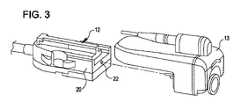
図1-3は、近位シャシー12、器具シャフト14、および患者の組織を把持するように関節運動されることができる上側ジョー部18を有する遠位エンドエフェクタ16を含む手術ツール10を示す。近位シャシー12は、参照により本明細書に組み込まれる、米国特許出願公開第2014/0183244号明細書に開示されているシステムのような、遠隔手術システムの対応する出力カプラとインタフェース接続し且つそれによって駆動され得る入力カプラ22を含む。入力カプラ22は、器具シャフト14内に配置されている1つまたは複数の入力部材と駆動的に結合されている。入力部材は、エンドエフェクタ16と駆動的に結合されている。図2および3に示すように、近位シャシー12の入力カプラ22は、参照により本明細書に組み込まれる、米国特許第8,912,746号に開示されているステープラ専用のモータパック、または米国特許第8,529,582号に開示されている汎用モータパックのような、様々な種類のモータパック13と接続する(mate with)ように構成されることができる。 1-3 show a
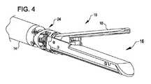
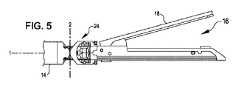
図4-6は、エンドエフェクタ16を含む手術ツール10の遠位端部の斜視図、側面図、および上面図を示す。エンドエフェクタ16は、手首部アセンブリ24によって器具シャフト14に移動可能に接続されている。手首部アセンブリ24は、少なくとも2自由度を有し、器具シャフト14に対して直交する2つの軸回りのエンドエフェクタ16の関節運動のために、細長い器具シャフト14へのエンドエフェクタ16の取り付けを提供する。手首部アセンブリ24は、器具シャフト14が沿って延びる軸1に対して垂直である軸2の周りで器具シャフト14に対してエンドエフェクタ16をヨー回転させるように構成されている。手首部アセンブリ24はまた、軸1および軸2に垂直である軸3の周りで器具シャフト14に対してエンドエフェクタ16をピッチ回転させるように構成されている。図示のように、ヨー軸2はピッチ軸3に対して近位(エンドエフェクタ16からより遠い)であるが、これは必要条件ではなく、いくつかの実施形態では、ヨー軸2はピッチ軸3の遠位にある。 4-6 show perspective, side and top views of the distal end of
図7および8は、上側ジョー部18および下側ジョー部26を含むエンドエフェクタ16の詳細を示す断面図である。下側ジョー部26は、取り外し可能または非取り外し可能ステープルカートリッジを収容および支持するように構成されることができる。上側ジョー部18は、組織をクランプするために下側ジョー部26に対して関節運動するように下側ジョー部26と枢動可能に結合されている。ビーム部材28が、上側ジョー部を関節運動させるために図7に示す近位状態から図8に示す遠位状態に駆動される。ビーム部材28の移動は、下側ジョー部26に対して組織上に上側ジョー部18を強制的に固定するように働くことができる。オプションで、ビーム部材28はまた、組織を切断し、カートリッジから切断された組織にステープルを展開することを可能にし得る。
7 and 8 are cross-sectional views showing details of
ビーム部材28は、上側ジョー部18のレール機構32内でスライドするように構成された上側ビーム部30を含む。レール機構32は、上側ビーム部分30が最近位ガレージ領域36から係合するための傾斜路34を含む。図7に示す開位置は、ばねのような弾性装置によって維持されることができる、または二次機構(図示せず)によって開閉されることができる。上側ジョー部18の部分的な閉鎖は、傾斜路34上への上側ビーム部分30の遠位移動に影響され得る。上側ジョー部18の完全な閉鎖は、上側ビーム部分30が傾斜路34を越えてレール機構32上を遠位に動かされるときに達成される。傾斜路34から離れる上側ビーム部分30の近位移動は、ビーム部材28によって上側ジョー部18に加えられた閉鎖力を取り除く。次いで、弾性装置または二次機構が、閉じたまたは部分的に閉じた上側ジョー部18を開かせることができる。したがって、傾斜路34に沿った上側ビーム部分30の前後移動は、エンドエフェクタ16の開閉を切り替えることができる。
ビーム部材28はまた、下側ジョー部18のレール機構内でスライドするように構成された下側ビーム部分38を含む。下側ビーム部分38は、ビーム部材28の遠位移動中に下側ジョー部26からステープルを排出するように構成された(米国特許出願公開第2014/0183244号に開示されているような)スレッド(sled)を作動させることができる。代替的には、下側ビーム部分38はそのようなスレッドと一体化されることができる。
図9は、ビーム部材28の図を示す。ここで、上側ビーム部分30は、組織を切断するように構成された一体型切断部材40を含む。しかし、他の実施形態では、組織切断装置は、ビーム部材28から分離されることができ、または異なる方法でビーム部材28内に実装されることができる。上側ビーム部分30は、一体型切断部材40から横方向に延びる上側フランジ42を含む。上側フランジ部分42は、レール機構32および傾斜路34と直接連結するように構成されている。同様の方法で、下側フランジ44が、下側ジョー部26のレール機構でスライドするように設けられる。細長い作動アセンブリ46が、ビーム部材28に遠位方向および近位方向への移動を提供するために、ビーム部材28に取り付けられている。 FIG. 9 shows a view of
図10-12は、ビーム部材28および作動アセンブリ46の断面図を示す。作動アセンブリ46は、押圧アセンブリ48および引張アセンブリ50を含む。図示された実施形態では、押圧アセンブリ48は、密巻コイルばねとして構成され、ビーム部材28への駆動ロッド52からの圧縮力を伝えるように適合されている。押圧アセンブリ48は、例えば、PTFEのような潤滑性ポリマー材料のような任意の適切な材料から構成することができるシース54によって外側から拘束されることができる。押圧アセンブリ48のコイル状設計は、ビーム部材28を遠位方向に押すために圧縮力がビーム部材28に効率的に伝えられることを可能にする。押圧アセンブリ48は、任意の適切な方法で構成されることができる。例えば、幾つかの実施形態では、押圧アセンブリ48は、コイル状ワイヤから構成されることができる。幾つかの実施形態では、押圧アセンブリ48は、チューブから螺旋状に切断される。場合によっては、押圧アセンブリの圧縮要素(例えば、コイル)は、張力下で分離するため、そのような場合、押圧アセンブリは主に圧縮力を伝達するために用いられ得る。 10-12 show cross-sectional views of
引張アセンブリ50は、任意の適切な材料又は引張荷重に対抗することができる要素(例えば、編組ケーブルまたは可撓性ロッド)から構成されることができる。いくつかの実施形態では、引張アセンブリ50は、圧着部分(crimp portion)56によってビーム部材28内に保持され得る。場合によっては、引張アセンブリ50は、それ自体がつぶれたり座屈したりする傾向を有し得るので、ビーム部材28への駆動ロッド52からの圧縮力を伝達することに比較的効果がない可能性があり、したがって、そのような場合、引張アセンブリ50は主に引張力を伝達するために用いられ得る。引張アセンブリ50は、駆動ロッド52によってビーム部材28に加えられた引張力を伝達するように適合されている。駆動ロッド52は器具シャフト14内に配置され、図1に示される入力カプラ22の1つまたは複数に駆動可能に結合される。引張アセンブリ50は、引張力が駆動ロッド52からビーム部材28に効果的に伝達され、ビーム部材28を近位方向に引っ張ることを可能にする。押圧アセンブリ48および引張アセンブリ50は、引張アセンブリ50を介して引張力をおよび押圧アセンブリ48を介して圧縮力を伝達することによって、ビーム部材28に遠位および近位の運動を提供するように相補的な方法で動作する。引張アセンブリ50を介して引張力をおよび押圧アセンブリ48を介して圧縮力を伝達することは、作動アセンブリ46の非常に柔軟かつコンパクトな設計を可能にし、動作中に比較的大きいヨー角度およびピッチ角度で配置されることができる手首部24内で作動アセンブリ46が並進運動することを可能にする特性を可能にする。
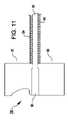
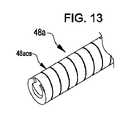
押圧アセンブリ48は、所与の固定内径および外径に対して実質的に連続的な外形およびより大きく/より硬いワイヤ部分を提供するために円筒形の外径を有することができる。例えば、図13および14は、円筒形外面48aosを有する押圧アセンブリ48aを示す。コイルばねを研削して円筒形外面48aosを形成するような、任意の適切な手法が押圧アセンブリ48aを製造するために使用されることができる。 Pressing
押圧アセンブリ48は、境界を接する凸面/凹面を有する密巻ばねを含むことができる。例えば、図15および16は、分布接触応力を増大させかつ丸ワイヤコイルばねに対してコラム安定性(column stability)を向上させるためにコイルの隣接する部分と一緒にぴったり重なる境界を接する凸/凹面を有する押圧アセンブリ48bを示す。 The biasing
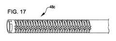
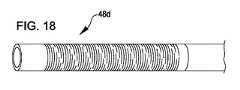
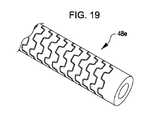
押圧アセンブリ48は、図10-16に示されるような密巻コイルばね設計に限定されない。例えば、図17-19は、実質的に圧縮剛性を低下させることなく、手首部24で押圧アセンブリの曲げ柔軟性を増加させるために、手首部24の近傍において中実チューブにパターンを局所的に切り込むことによって中実チューブから形成されることができる可撓性の押圧アセンブリ48c、48d、48eを示す。押圧アセンブリ48c、48d、48eは、任意の適切な材料(例えば、適切な金属、適切なポリマーベースの材料)から作られたチューブにパターンをレーザーカットすることにより形成されることができる。図17に示す押圧アセンブリ48cでは、パターンは、ギャップがチューブに形成されるところでの可撓性を高めるとともに材料が適所に残されるところでの軸方向の剛性を保つ。図18に示す押圧アセンブリ48dは、らせん状パターンに配置された複数の円周方向スリットを有する。図19に示す押圧アセンブリ48eでは、パターンは、組み合い(interlocking)セグメントの相対的な変位を抑制しながら柔軟性を提供する別々の組み合いセグメントを形成する。 The biasing
押圧アセンブリ48は、別々の境界を接するセグメントの任意の適切な構成から形成することができる。例えば、図20は、平ワッシャの積み重ねから作られた押圧アセンブリ48fを示す。図21および22は、円環ディスクの積み重ねから作られた押圧アセンブリ48gを示す。図23および24は、円錐ワッシャの積み重ねから作られた押圧アセンブリ48hを示している。円錐ワッシャの夫々は、円錐ワッシャの相対的な横方向の動きを抑制して円錐ワッシャの中心を通って延びる引張アセンブリ50との円錐ワッシャの整列を強化するように相互作用する非平面状のインタフェース(境界を接する)面(例えば球状インタフェース面)を有する。円錐ワッシャの形状の結果として、押圧アセンブリ48hは、隣接する円錐ワッシャ間の任意の方向の相対的な滑動を介して、作動アセンブリ46の局所軸方向を横切る任意の方向の押圧アセンブリ48hの曲がりに適応する。 Pressing
押圧アセンブリ48は、任意の適切な非軸対称の境界を接するセグメントの積み重ねから形成することができる。例えば、図25は、別個の非軸対称部材70の積み重ねから作られた押圧アセンブリ48iを示す。図26は、部材70のうちの1つの異なる図を示す。図示の実施形態では、部材70は、横方向に向けて突出する領域72と、隣接部材70の突出する領域72を収容し且つこれと接するように成形された横方向に向けて凹んだ領域74とを有する。突出する領域72および凹んだ領域74は、隣接する部材70間の相対的な滑りを、領域72、74が押圧アセンブリ48iの局所的な延在方向に対して横方向に延在する方向に制限するように形作られている。インタフェース(境界を接する)領域72、74はまた、押圧アセンブリ48iの局所的な延在方向の周りの隣接部材70間の相対的なねじれを抑制するように働き、それによって、押圧アセンブリ48iの近位端部と遠位端部との間の押圧アセンブリ48iのねじれを抑制する。 The
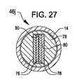
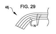
作動アセンブリ46は、細長い板金ストリップのスタックを含み得る。例えば、図27は、図1-6の手術ツールの作動アセンブリ46jの断面図を示す。作動アセンブリ46jは、板金ストリップ76の平面を横切る作動アセンブリ46jの撓み(flexure)、ならびに作動アセンブリ46jの長さに沿った作動アセンブリ46jのねじれに適応しながら、圧縮荷重および引張荷重の両方に対抗する(react)ように構成された細長い板金ストリップ76を含む。作動アセンブリ46jは、それを通って板金ストリップ76が作動アセンブリ46jの近位端部から作動アセンブリ46jの遠位端部まで延びる長方形のチャネル80を有する外側シース78を含む。外側シース78は、ビーム部材28の遠位前進中に板金ストリップが圧縮で負荷を与えられるときに板金ストリップ76の横方向の座屈を防止するように板金ストリップ76の積み重ねを拘束する。図28は、器具シャフト14に対するエンドエフェクタ16の回転に応答して引き起こされ得る作動アセンブリ46jのねじれおよびそれに関連する板金ストリップ76のねじれを示す。図29は、器具シャフト14に対するエンドエフェクタ16の再配向(reorientation)に応答して引き起こされ得る手首部アセンブリ24の近傍における板金ストリップ76の撓みを示す。
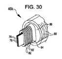
作動アセンブリ46は、駆動ロッド52とビーム部材28との間で引張荷重を伝達するための細長い板金バンドの積み重ねと、駆動ロッド52とビーム部材28との間で圧縮荷重を伝達するための矩形ワッシャの積み重ねとを含むことができる。例えば、図30は、駆動ロッド52とビーム部材28との間に取り付けられそれらの間に延在する板金ストリップ76の積み重ねを含む作動アセンブリ46kの等角図を示す。作動アセンブリ46kでは、板金ストリップ76は、ビーム部材28の近位後退中に駆動ロッド52からビーム部材28へ引張荷重を伝達する。作動アセンブリ46kはさらに、ビーム部材28の遠位前進中に駆動ロッド52からビーム部材28へ圧縮荷重を伝達する矩形ワッシャ82の積み重ねを含む。作動アセンブリ46kはさらに、矩形ワッシャ82を収容する管腔を有する内側シース84と、内側シース84を収容する管腔を有する外側シース86とを含む。図示された実施形態では、外側シース86は、手首部24を介した器具シャフト14に対するエンドエフェクタ16の再配向に応答して、板金ストリップ76の平面を横切って曲がるように外側シース86の可撓性を高めるために、手首部アセンブリ24の近くに一連の凹部88を有する。
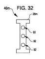
作動アセンブリ46は、複数の可撓性作動ロッドを含むことができる。例えば、図31は、図1-6の手術ツールの作動アセンブリ46mの遠位部分の側面図を示す。作動アセンブリ46mは、駆動ロッド52からビーム部材28mへの張力と駆動ロッド52からビーム部材28mへの圧縮力との両方を伝達するように適合された3つの可撓性作動ロッド90を含む。3つの可撓性作動ロッド90は、共通平面内に整列され、それによって共通平面を横切る作動ロッド90の撓みに適応する。3つの可撓性作動ロッド90は、駆動ロッド52とビーム部材28mとの間で別々に経路を定められ、それによって器具シャフト14に対するエンドエフェクタ16の回転に応答して引き起こされ得る作動ロッド90のねじれに適応する。図32は、それを介して作動ロッド90がビーム部材28mに結合されるビーム部材28mの開口部92を示す作動アセンブリ90gのビーム部材28mの端面図を示している。
作動アセンブリ46は、引張アセンブリ50の代わりに、圧縮荷重および引張荷重の両方を駆動ロッド52からビーム部材28に伝達する要素を使用することができる。例えば、図33は、引張アセンブリ50の代わりにニチノールワイヤ50aを含む作動アセンブリ46nを示す。ニチノールワイヤ50aは、ビーム部材28を遠位方向に前進させかつ近位方向に後退させる両方を行うために駆動ロッド52からビーム部材28に圧縮荷重および引張荷重の両方を伝達する。図示の実施形態では、作動アセンブリ46nはばね48nを含み、これは密巻ばね(closed coil spring)であり得るが、そうである必要はない。ばね48nは、ビーム部材28の遠位前進中に駆動ロッド52からビーム部材28への圧縮荷重の伝達をニチノールワイヤ50aと共有するように構成することができる。ばね48nは、ビーム部材28の遠位前進中に駆動ロッド52からビーム部材28への圧縮荷重の伝達をニチノールワイヤ50aと共有しないように構成することもできる。多くの実施形態では、バネ48nの主な機能は、ニチノールワイヤが駆動ロッド52の直径に一致する直径を有することができるようにニチノールワイヤ50aへの半径方向の支持を提供することである。ニチノールワイヤ50aをビーム部材28および駆動ロッド52のそれぞれに取り付けるために、例えばカシメ、ハンダ付け、溶接などの任意の適切な手法を使用することができる。 The
作動アセンブリ46のいくつかの実施形態では、押圧部材48は、引張部材50の管腔内に配置されている。例えば、図34は、押圧アセンブリ48oと、押圧アセンブリ48oが配置されている管腔を有する引張アセンブリ50oとを含む作動アセンブリ46oを示す。作動アセンブリ46oの構成は、押圧アセンブリ48が引張アセンブリ50を同心円状に取り囲む本明細書に記載の他の実施形態とは異なる。作動アセンブリ46oでは、引張アセンブリ50oは、押圧アセンブリ48oを封入するシース(例えば編組シース)を有する。押圧アセンブリ48oは、可撓性ロッド66によって接合された複数の球状部材(例えば、ボールベアリング)を含む。押圧アセンブリ48oおよび引張アセンブリ50oの両方は、図1に示す入力カプラ22の1つまたは複数に駆動可能に結合されている駆動ロッド52によって作動される。 In some embodiments of
図35および36は、手首部アセンブリ24の斜視図および断面図を示す。手首部アセンブリ24は、近位外側リンク100、中間外側リンク102、および遠位外側リンク104を含む。これら3つのリンクは、手首部アセンブリ24の運動学的ピッチおよびヨー運動を決定する。図示のように、近位外側リンク100と中間外側リンク102との間の接点部(interface)は、手首部アセンブリ24のヨー運動を決定する。外側遠位リンク104と中間外側リンク102との間の接点部は、手首部アセンブリ24のピッチ運動を決定する。しかし、代替の手首部構成では、この関係は、(例えば、手首部アセンブリ24に対してエンドエフェクタ16を90度回転させることによって)手首部アセンブリ24が近位外側リンク100と中間外側リンク102との間でピッチ回転し、遠位外側リンク100と中間外側リンク102との間でヨー回転するように逆にされることができる。 35 and 36 show perspective and cross-sectional views of
ケーブル部分106は、手首部アセンブリ24に張力を加え、手首部アセンブリに動きを与えるように作動される。一実施形態では、ケーブル部分106は、遠位外側リンク104の一部分に個々に固定されることができる。機能的に均等な代替実施形態では、図35に示されるように、ケーブル部分106は、示されるように遠位外側リンク104の一部分の周りにループにされる。ケーブル部分106を遠位外側リンク104にループさせることは、ケーブル部分106を遠位外側リンク104に固定し、ケーブル部分106がスリップすることを防ぐ。どちらの実施形態でも、張力が、手首部を関節運動させるように引っ張られることになる個々のケーブル部分106に加えられる。ケーブル部分106に加えられる差動力(Differential forces)は、様々な角度でピッチ回転およびヨー回転させるように手首部アセンブリを作動させることができる。ケーブル部分106は、図1に示される入力カプラ22のうちの1つまたは複数に駆動可能に結合されることができる。手首部アセンブリはまた、近位内側リンク108および遠位内側リンク110を含み、これらは以下で詳細に論議される。
図37に注目すると、図35および36Bに示す外側リンク間の接点部を表すジョイント112の例示的実施形態が示されている。ジョイント112は、第1リンク114および第2のリンク116を含む。第1リンク114は、歯116、118およびベアリング(支持)突出部(bearing projection)122を含み得る。ディスク720は、ピン124、126、128およびベアリング突出部130を含む。例示的な実施形態によれば、第1および第2のリンク114、116の突出部122、130は、ケーブル部分106が通過することを可能にする通路を含み得る。ベアリング突出部122、130は中央開口部134、136に対して外側位置に配置されているので、ベアリング突出部122、130に隣接する通路を通って延びるケーブル部分106もまた外側位置に配置されている。これは、中央開口部134、136を通る他の機構の経路設定(routing)を可能にする。リンク間の作動運動学は、運動中に係合および係合解除するピンおよび歯の形状によって決定される。ベアリング突出部122、130は、ピンおよび歯への圧縮歪みを減少させるのを助けるために全ての角運動を通していくつかのポイントで係合する曲面を含んでいた。 Directing attention to FIG. 37, there is shown an exemplary embodiment of joint 112 representing the contact between the outer links shown in FIGS. 35 and 36B.
ジョイント112によって提供される拡大された運動範囲により、ジョイント112を含む手首部は、より少ない部品によるより効率的な方法で、ピッチまたはヨー方向に±90度のような所望の量の運動を提供し得る。各ジョイントが約45度の最大ロール角に制限される従来の手首部構造では、直列のいくつかのそのようなジョイントが、手首部機構全体のための比較的大きなロール角に必要とされる。図示のように実施形態では、単一のジョイントが最大90度のロール角制限を提供することができる。その結果、1つまたは複数のジョイント112を含む手首部の製造コストおよび複雑さが低減される一方依然として関節運動に対する所望の制御を達成することができる。加えて、ジョイント112のリンク114、116に含まれる複数の歯および対応する複数のピンは、例えば、ディスクを中立位置(例えば、ゼロ角度ロールアラインメント)に戻すことを含む、リンク114、116を正確に位置決めするのを助けるために、および、リンク114、116が互いに対する方向に回転されるときのように、リンク114、116間の動きの滑らかさを高めるために、向上されたタイミングを提供することができる。例示的な実施形態によれば、手首部は、例えば、ピッチまたはヨー方向の最大±180度の運動範囲を有する手首部のような、より高い運動範囲(ロール限界角度まで)を達成するために複数のジョイント112を含み得る。ジョイント112、および本明細書に開示された実施形態と共に使用可能な他のジョイントのさらなる詳細は、国際公開第2015/127250号に開示されており、これは参照により本明細書に組み込まれる。 Due to the extended range of motion provided by joint 112, the wrist including joint 112 provides a desired amount of motion, such as ±90 degrees in the pitch or yaw direction, in a more efficient manner with fewer parts. can. In conventional wrist constructions where each joint is limited to a maximum roll angle of about 45 degrees, several such joints in series are required for a relatively large roll angle for the entire wrist mechanism. In the illustrated embodiment, a single joint can provide a roll angle limit of up to 90 degrees. As a result, the manufacturing cost and complexity of a wrist including one or
図36に示すように、近位内側リンク108および遠位内側リンク110は、軸1に沿って空間的に分離され、互いに90度オフセットされている(ずれている)。したがって、近位内側リンク108は部分的にしか示されていない。近位および遠位内側リンク108、110の半径方向表面は、突出部を含む(例えば、クレビスピン(clevis pins)140として構成されている)。クレビスピンは、外部リンクの内側表面で(例えばクレビスジョイント(clevis joints)142として構成された)くぼみの間を接続する。クレビスピン140およびジョイント142は、外側リンクのジョイント間の距離を設定するが、そうでなければ受動的であり、歯とピンの幾何学的形状によって決定される外側リンクのジョイント運動学を変えない。近位および遠位内側リンク108、110の各側部は、内側リンク108、110あたり合計4つのクレビスピン140のための外側リンクへの各接続部に対する共通に整列した(commonly aligned)クレビスピンのペアを含む。クレビスピン140の各ペアは、作動アセンブリ46のための内部通路144を提供するために分離される。 As shown in FIG. 36, proximal
追加の内部シース146が、作動アセンブリ46をさらに支持するために使用されることができる。作動アセンブリ46は、内部シース146内で軸方向にスライドする。内部シース146は、手首部アセンブリ24の遠位端部分に固定され、手首部アセンブリ24の動きとともに曲がるように可撓性であるが、軸方向には動かない。内側リンクによって提供される内部シース146および内部通路144は、軸方向移動中に作動アセンブリ46を案内し且つ拘束するように働く。内部シース146および内部通路144は、圧縮荷重(すなわち、切断およびステープル留め中の遠位運動)下で作動アセンブリが座屈するのを防止する。前述の国際公開第2015/127250号に開示されているような従来の手首部のデザインは、外側リンクを定位置に維持するために張力をかけたケーブルに頼っている。作動アセンブリ46が遠位方向に移動するとき、結果として生じる圧縮力はケーブルにたるみを誘発し得るので、ここではそれは不十分である。しかし、作動アセンブリ46が遠位方向に移動するとき、内側リンク108、110のクレビスピン140は有利に外側リンクを所定の位置に維持し、そのため、手首部アセンブリ24の構造を維持する。 An additional
各内側リンクは、図38乃至40に示すようにツーピース構造を有することができ、これらの図は、内側リンクを外側リンクに組み立てるための技法も示している。図38において、近位内側リンク108の第1のリンク部分108aおよび第2のリンク部分108bは、クレビスピン140を中間外側リンク102のクレビスジョイント142内に配置するように位置決めされる。第1のリンク部分108aおよび第2のリンク部分108bは、各部分のギア歯148が互いに噛み合って、その部分を図39に示す構造に整列させるように、斜めに挿入される。ギア歯148は、ピンまたは他の留め具の必要性を排除する組み立て補助具であり、組み立ての他に運動のためには使用されない。しかし、いくつかの実施形態では、留め具がギア歯の代わりに使用されることができる。リンク部分108a、108bが完全な内側近位リンク108に組み立てられた後、近位外側リンク100が残りの露出したクレビスピン140の上に組み立てられて図40に示す構造になる。一実施形態では、図40に示されるように、近位外側リンク100もまたツーピース構造である。 Each inner link can have a two-piece construction as shown in Figures 38-40, which also show techniques for assembling the inner link to the outer link. 38, first link portion 108a and second link portion 108b of proximal
他の変形は本発明の精神の範囲内である。説明した実施形態の様々な態様、実施形態、実装形態または特徴は、別々にまたは任意の組み合わせで使用することができる。遠隔手術ツールの動作に関連する記載された実施形態の様々な態様は、ソフトウェア、ハードウェア、またはハードウェアとソフトウェアの組み合わせによって実施することができる。したがって、本発明は様々な修正形態および代替構成を受け入れる余地があるが、その特定の例示の実施形態は図面に示されており、上で詳細に説明されてきた。しかし、開示された特定の形態に本発明を限定する意図はないが、それどころか、その意図は、添付の特許請求の範囲に定義されるように、本発明の精神および範囲内にあるすべての修正形態、代替構造、および均等物を包含することであることが理解されるべきである。 Other variations are within the spirit of the invention. Various aspects, embodiments, implementations or features of the described embodiments may be used separately or in any combination. Various aspects of the described embodiments relating to operation of the telesurgical tool can be implemented in software, hardware, or a combination of hardware and software. Accordingly, while the invention is susceptible to various modifications and alternative constructions, specific exemplary embodiments thereof have been shown in the drawings and have been described in detail above. There is no intention, however, to limit the invention to the particular forms disclosed, but rather to include all modifications that come within the spirit and scope of the invention as defined in the appended claims. It should be understood to encompass forms, alternative constructions and equivalents.
本発明を説明する文脈における(特に以下の特許請求の範囲の文脈における)用語“a”および“an”および“the”および類似の指示対象の使用は、そうでないことが本明細書に示されるか、または文脈により明らかに否定される場合を除き、単数形および複数形の両方を包含すると解釈されるべきである。用語「備える」、「有する」、「含む」、および「含有する」は、特に断りのない限り、オープンエンドの用語(すなわち、「含むが、これに限定されない」を意味する)として解釈されるべきである。「接続された」という用語は、たとえ介在するものがあったとしても、部分的にまたは全体的にその中に含まれる、それに取り付けられる、または一緒に接合されると解釈されるべきである。本明細書における値の範囲の列挙は、本明細書において別段の指定がない限り、単にその範囲内に含まれる各個別の値を個々に指す簡潔な方法として役立つことを意図しており、各個別の値は、あたかも本明細書に個々に記載されているかのように本明細書に組み込まれる。本明細書に記載のすべての方法は、本明細書に別段の指示がない限りまたは文脈によって明らかに矛盾しない限り、任意の適切な順序で実行することができる。本明細書で提供されるありとあらゆる例、または例示的な言語(例えば、「のような」)の使用は、単に本発明の実施形態をよりよく明らかにすることを意図しており、特に請求項に記載されない限り本発明の範囲の限定をもたらさない。本明細書中のいかなる言語も、請求項に記載されていない要素を本発明の実施に必須であると示すと解釈されるべきではない。 The use of the terms "a" and "an" and "the" and similar referents in the context of describing the present invention (especially in the context of the claims below) is hereby indicated otherwise. or should be construed to include both singular and plural forms unless the context clearly dictates otherwise. The terms "comprising," "having," "including," and "containing" are to be interpreted as open-ended terms (i.e., meaning "including, but not limited to") unless otherwise specified should. The term "connected" is to be interpreted as partially or wholly contained within, attached to, or joined together even if there is an intervening object. Any recitation of ranges of values herein, unless otherwise specified herein, is intended merely to serve as a shorthand method of individually referring to each individual value falling within the range; Individual values are incorporated herein as if individually set forth herein. All methods described herein can be performed in any suitable order unless otherwise indicated herein or otherwise clearly contradicted by context. Any and all examples, or use of exemplary language (e.g., "like") provided herein, is merely intended to better clarify the embodiments of the present invention, particularly the claims. does not impose any limitation on the scope of the invention unless stated herein. No language in the specification should be construed as indicating any non-claimed element as essential to the practice of the invention.
本発明を実施するために本発明者らが知っている最良の形態を含む、本発明の好ましい実施形態が本明細書に記載されている。これらの好ましい実施形態の変形は、前述の説明を読めば当業者には明らかになるであろう。本発明者らは、当業者がそのような変形を適切に使用することを期待し、そして本発明者らは本明細書に具体的に記載されたものとは別の方法で本発明を実施することを意図する。したがって、本発明は、適用法によって許容されるように、本明細書に添付の特許請求の範囲に列挙されている主題のすべての修正形態および均等物を含む。さらに、そのすべての可能な変形形態における上記の要素の任意の組み合わせは、本明細書中に別段の指示がない限りまたは文脈によって明らかに矛盾しない限り、本発明に包含される。 Preferred embodiments of this invention are described herein, including the best mode known to the inventors for carrying out the invention. Variations of those preferred embodiments will become apparent to those of ordinary skill in the art upon reading the foregoing description. The inventors expect those skilled in the art to employ such variations as appropriate, and the inventors practice the invention in ways other than those specifically described herein. intended to Accordingly, this invention includes all modifications and equivalents of the subject matter recited in the claims appended hereto as permitted by applicable law. Moreover, any combination of the above-described elements in all possible variations thereof is encompassed by the invention unless otherwise indicated herein or otherwise clearly contradicted by context.
Claims (15)
Translated fromJapanese器具シャフトと;
前記エンドエフェクタを前記器具シャフトに移動可能に接続する手首部アセンブリであって、前記手首部アセンブリは、前記器具シャフトに対して直交する2つの軸周りに前記器具シャフトに対して前記エンドエフェクタを関節運動させるように動作可能であり、前記手首部アセンブリは、内部通路を有する内部シースを有し、前記内部シースは、前記手首部アセンブリの動きとともに曲がるように可撓性であるが、軸方向には動かない、手首部アセンブリと;
前記上側ジョー部および前記下側ジョー部内で並進するように配置されているビーム部材であって、前記上側ジョー部に移動可能に結合するための第1の部分および前記下側ジョー部に移動可能に結合するための第2の部分を有し、前記第1の部分は前記上側ジョー部のレール機構内でスライドするように構成され、前記第2の部分は前記下側ジョー部のレール機構内でスライドするように構成される、ビーム部材と;
押圧アセンブリおよび引張アセンブリを有する作動アセンブリであって、前記引張アセンブリは、引張力を前記ビーム部材に伝達するように構成され、前記押圧アセンブリは、圧縮力を前記ビーム部材に伝達するように構成され、前記引張アセンブリおよび前記押圧アセンブリは、前記引張アセンブリを介して引張力をおよび前記押圧アセンブリを介して圧縮力を伝達することによって、前記ビーム部材に遠位および近位の運動を提供するように相補的な方法で動作し、前記作動アセンブリは前記内部通路を通って延び、前記作動アセンブリは、前記内部シースに対する前記作動アセンブリの移動の間に、前記内部シース内で軸方向にスライドする、作動アセンブリと;
を有する、
手術装置。An end effector having upper and lower jaws and:
an instrument shaft;
A wrist assembly movably connecting the end effector to the instrument shaft, the wrist assembly moving the end effector relative to the instrument shaft about twoaxesorthogonal to the instrument shaft. Operable to articulate, the wrist assembly has an inner sheath having an inner passageway, the inner sheath flexible to flex with movement of the wrist assembly, but axially movable. the wrist assembly and;
A beam member disposed for translation within said upper jaw portion and said lower jaw portion, said beam member being movable to said lower jaw portion and a first portion for movably coupling to said upper jaw portion. a second portion for coupling to a second portion, the first portion being configured to slide within the railing mechanism of the upper jaw portion and the second portion being configured to slide within the railing mechanism of the lower jaw portion; a beam member configured to slide on ;
An actuation assembly having a biasing assembly and a tensioning assembly, the tensioning assembly configured to transmit atension force to the beam member and the biasing assembly configured to transmit acompression force to the beam memberand wherein said tensioning assembly and said pushing assembly provide distal and proximal motion to said beam member by transmitting tensile force through said tensioning assembly and compressive force through said pushing assembly. wherein said actuation assembly extends through said inner passageway,said actuation assemblysliding axially within said inner sheath during movement of said actuation assembly relative to said inner sheath. an actuation assembly;
has a
surgical equipment.
前記押圧アセンブリは、前記細長いケーブルを囲む内腔を有する、
請求項1に記載の手術装置。The tensioning assembly has an elongated cable, and
the compression assembly has a lumen surrounding the elongated cable;
The surgical device according to claim 1.
請求項1に記載の手術装置。the biasing assembly has a close coil spring;
The surgical device according to claim 1.
請求項3に記載の手術装置。the close-wound spring has a cylindrical outer surface, or has bounding convex and concave surfaces, or comprises a helically cut tube;
The surgical device according to claim 3.
請求項1に記載の手術装置。the pressing assembly has a tube with a pattern of recesses;
The surgical device according to claim 1.
請求項1に記載の手術装置。the pressing assembly has a plurality of pressing elements that separate under tension;
The surgical device according to claim 1.
前記引張アセンブリは、前記球形部材を収容する内腔を画定する、
請求項6に記載の手術装置。The pressing assembly has a plurality of spherical members,
the tensioning assembly defines a lumen that houses the spherical member;
The surgical device according to claim 6.
請求項7に記載の手術装置。the spherical members are connected by flexible rods;
The surgical device according to claim 7.
請求項1に記載の手術装置。The pressing assembly comprises a plurality of separate elements having an interface that limits relative lateral slippage between the separate elements in one direction.
The surgical device according to claim 1.
請求項1に記載の手術装置。wherein the pressing assembly comprises a plurality of separate elements having an interface that prevents relative twisting between the separate elements;
The surgical device according to claim 1.
請求項1に記載の手術装置。the pressing assembly comprises a stack of flat washers,
The surgical device according to claim 1.
請求項1に記載の手術装置。the pressing assembly comprises a stack of annular discs;
The surgical device according to claim 1.
前記押圧アセンブリは、前記複数の板金バンドがそれを通って延在する管腔を画定する矩形ワッシャの積み重ねを有する、
請求項1に記載の手術装置。the tension assembly having a plurality of sheet metal bands;
the pressing assembly has a stack of rectangular washers defining a lumen through which the plurality of sheet metal bands extend;
The surgical device according to claim 1.
前記引張アセンブリは、前記可撓性ロッドの一次元アレイを有し、
前記可撓性ロッドの一次元アレイは、前記引張力を前記ビーム部材に伝達し、
前記可撓性ロッドの一次元アレイは、前記圧縮力を前記ビーム部材に伝達する、
請求項1に記載の手術装置。The pressing assembly has a one-dimensional array of flexible rods;
said tensioning assembly having a one-dimensional array of said flexible rods;
said one-dimensional array of flexible rods transmitting said tensile force to said beam member;
the one-dimensional array of flexible rods transmit the compressive force to the beam member;
The surgical device according to claim 1.
前記引張アセンブリは、前記ニッケル-チタンロッドを有し、
前記ニッケル-チタンロッドは、前記引張力を前記ビーム部材に伝達し、
前記ニッケル-チタンロッドは、前記圧縮力を前記ビーム部材に伝達する、
請求項1に記載の手術装置。the pressing assembly has a nickel-titanium rod;
said tensioning assembly having said nickel-titanium rod;
said nickel-titanium rod transmitting said tensile force to said beam member;
the nickel-titanium rod transmits the compressive force to the beam member;
The surgical device according to claim 1.
Priority Applications (2)
| Application Number | Priority Date | Filing Date | Title |
|---|---|---|---|
| JP2022133148AJP7428761B2 (en) | 2016-09-09 | 2022-08-24 | Stapler beam structure |
| JP2024009158AJP2024028614A (en) | 2016-09-09 | 2024-01-25 | Stapler beam structure |
Applications Claiming Priority (3)
| Application Number | Priority Date | Filing Date | Title |
|---|---|---|---|
| US201662385636P | 2016-09-09 | 2016-09-09 | |
| US62/385,636 | 2016-09-09 | ||
| PCT/US2017/050735WO2018049198A1 (en) | 2016-09-09 | 2017-09-08 | Stapler beam architecture |
Related Child Applications (1)
| Application Number | Title | Priority Date | Filing Date |
|---|---|---|---|
| JP2022133148ADivisionJP7428761B2 (en) | 2016-09-09 | 2022-08-24 | Stapler beam structure |
Publications (2)
| Publication Number | Publication Date |
|---|---|
| JP2019526386A JP2019526386A (en) | 2019-09-19 |
| JP7130627B2true JP7130627B2 (en) | 2022-09-05 |
Family
ID=61562862
Family Applications (3)
| Application Number | Title | Priority Date | Filing Date |
|---|---|---|---|
| JP2019513355AActiveJP7130627B2 (en) | 2016-09-09 | 2017-09-08 | stapler beam structure |
| JP2022133148AActiveJP7428761B2 (en) | 2016-09-09 | 2022-08-24 | Stapler beam structure |
| JP2024009158APendingJP2024028614A (en) | 2016-09-09 | 2024-01-25 | Stapler beam structure |
Family Applications After (2)
| Application Number | Title | Priority Date | Filing Date |
|---|---|---|---|
| JP2022133148AActiveJP7428761B2 (en) | 2016-09-09 | 2022-08-24 | Stapler beam structure |
| JP2024009158APendingJP2024028614A (en) | 2016-09-09 | 2024-01-25 | Stapler beam structure |
Country Status (6)
| Country | Link |
|---|---|
| US (2) | US11166773B2 (en) |
| EP (1) | EP3509505A4 (en) |
| JP (3) | JP7130627B2 (en) |
| KR (3) | KR20240052889A (en) |
| CN (1) | CN109788952A (en) |
| WO (1) | WO2018049198A1 (en) |
Families Citing this family (277)
| Publication number | Priority date | Publication date | Assignee | Title |
|---|---|---|---|---|
| US20070084897A1 (en) | 2003-05-20 | 2007-04-19 | Shelton Frederick E Iv | Articulating surgical stapling instrument incorporating a two-piece e-beam firing mechanism |
| US9060770B2 (en) | 2003-05-20 | 2015-06-23 | Ethicon Endo-Surgery, Inc. | Robotically-driven surgical instrument with E-beam driver |
| US11998198B2 (en) | 2004-07-28 | 2024-06-04 | Cilag Gmbh International | Surgical stapling instrument incorporating a two-piece E-beam firing mechanism |
| US11890012B2 (en) | 2004-07-28 | 2024-02-06 | Cilag Gmbh International | Staple cartridge comprising cartridge body and attached support |
| US9072535B2 (en) | 2011-05-27 | 2015-07-07 | Ethicon Endo-Surgery, Inc. | Surgical stapling instruments with rotatable staple deployment arrangements |
| US11246590B2 (en) | 2005-08-31 | 2022-02-15 | Cilag Gmbh International | Staple cartridge including staple drivers having different unfired heights |
| US7669746B2 (en) | 2005-08-31 | 2010-03-02 | Ethicon Endo-Surgery, Inc. | Staple cartridges for forming staples having differing formed staple heights |
| US10159482B2 (en) | 2005-08-31 | 2018-12-25 | Ethicon Llc | Fastener cartridge assembly comprising a fixed anvil and different staple heights |
| US20070106317A1 (en) | 2005-11-09 | 2007-05-10 | Shelton Frederick E Iv | Hydraulically and electrically actuated articulation joints for surgical instruments |
| US20110295295A1 (en) | 2006-01-31 | 2011-12-01 | Ethicon Endo-Surgery, Inc. | Robotically-controlled surgical instrument having recording capabilities |
| US7845537B2 (en) | 2006-01-31 | 2010-12-07 | Ethicon Endo-Surgery, Inc. | Surgical instrument having recording capabilities |
| US8708213B2 (en) | 2006-01-31 | 2014-04-29 | Ethicon Endo-Surgery, Inc. | Surgical instrument having a feedback system |
| US11793518B2 (en) | 2006-01-31 | 2023-10-24 | Cilag Gmbh International | Powered surgical instruments with firing system lockout arrangements |
| US8186555B2 (en) | 2006-01-31 | 2012-05-29 | Ethicon Endo-Surgery, Inc. | Motor-driven surgical cutting and fastening instrument with mechanical closure system |
| US8820603B2 (en) | 2006-01-31 | 2014-09-02 | Ethicon Endo-Surgery, Inc. | Accessing data stored in a memory of a surgical instrument |
| US20120292367A1 (en) | 2006-01-31 | 2012-11-22 | Ethicon Endo-Surgery, Inc. | Robotically-controlled end effector |
| US8992422B2 (en) | 2006-03-23 | 2015-03-31 | Ethicon Endo-Surgery, Inc. | Robotically-controlled endoscopic accessory channel |
| US10568652B2 (en) | 2006-09-29 | 2020-02-25 | Ethicon Llc | Surgical staples having attached drivers of different heights and stapling instruments for deploying the same |
| US11980366B2 (en) | 2006-10-03 | 2024-05-14 | Cilag Gmbh International | Surgical instrument |
| US8632535B2 (en) | 2007-01-10 | 2014-01-21 | Ethicon Endo-Surgery, Inc. | Interlock and surgical instrument including same |
| US8684253B2 (en) | 2007-01-10 | 2014-04-01 | Ethicon Endo-Surgery, Inc. | Surgical instrument with wireless communication between a control unit of a robotic system and remote sensor |
| US20080169333A1 (en) | 2007-01-11 | 2008-07-17 | Shelton Frederick E | Surgical stapler end effector with tapered distal end |
| US8931682B2 (en) | 2007-06-04 | 2015-01-13 | Ethicon Endo-Surgery, Inc. | Robotically-controlled shaft based rotary drive systems for surgical instruments |
| US11564682B2 (en) | 2007-06-04 | 2023-01-31 | Cilag Gmbh International | Surgical stapler device |
| US7753245B2 (en) | 2007-06-22 | 2010-07-13 | Ethicon Endo-Surgery, Inc. | Surgical stapling instruments |
| US11849941B2 (en) | 2007-06-29 | 2023-12-26 | Cilag Gmbh International | Staple cartridge having staple cavities extending at a transverse angle relative to a longitudinal cartridge axis |
| US11986183B2 (en) | 2008-02-14 | 2024-05-21 | Cilag Gmbh International | Surgical cutting and fastening instrument comprising a plurality of sensors to measure an electrical parameter |
| US8573465B2 (en) | 2008-02-14 | 2013-11-05 | Ethicon Endo-Surgery, Inc. | Robotically-controlled surgical end effector system with rotary actuated closure systems |
| JP5410110B2 (en) | 2008-02-14 | 2014-02-05 | エシコン・エンド−サージェリィ・インコーポレイテッド | Surgical cutting / fixing instrument with RF electrode |
| US8636736B2 (en) | 2008-02-14 | 2014-01-28 | Ethicon Endo-Surgery, Inc. | Motorized surgical cutting and fastening instrument |
| US9585657B2 (en) | 2008-02-15 | 2017-03-07 | Ethicon Endo-Surgery, Llc | Actuator for releasing a layer of material from a surgical end effector |
| US9204923B2 (en) | 2008-07-16 | 2015-12-08 | Intuitive Surgical Operations, Inc. | Medical instrument electronically energized using drive cables |
| US9005230B2 (en) | 2008-09-23 | 2015-04-14 | Ethicon Endo-Surgery, Inc. | Motorized surgical instrument |
| US9386983B2 (en) | 2008-09-23 | 2016-07-12 | Ethicon Endo-Surgery, Llc | Robotically-controlled motorized surgical instrument |
| US11648005B2 (en) | 2008-09-23 | 2023-05-16 | Cilag Gmbh International | Robotically-controlled motorized surgical instrument with an end effector |
| US8210411B2 (en) | 2008-09-23 | 2012-07-03 | Ethicon Endo-Surgery, Inc. | Motor-driven surgical cutting instrument |
| US8608045B2 (en) | 2008-10-10 | 2013-12-17 | Ethicon Endo-Sugery, Inc. | Powered surgical cutting and stapling apparatus with manually retractable firing system |
| US8220688B2 (en) | 2009-12-24 | 2012-07-17 | Ethicon Endo-Surgery, Inc. | Motor-driven surgical cutting instrument with electric actuator directional control assembly |
| US9016542B2 (en) | 2010-09-30 | 2015-04-28 | Ethicon Endo-Surgery, Inc. | Staple cartridge comprising compressible distortion resistant components |
| US11812965B2 (en) | 2010-09-30 | 2023-11-14 | Cilag Gmbh International | Layer of material for a surgical end effector |
| US9629814B2 (en) | 2010-09-30 | 2017-04-25 | Ethicon Endo-Surgery, Llc | Tissue thickness compensator configured to redistribute compressive forces |
| US9788834B2 (en) | 2010-09-30 | 2017-10-17 | Ethicon Llc | Layer comprising deployable attachment members |
| US11925354B2 (en) | 2010-09-30 | 2024-03-12 | Cilag Gmbh International | Staple cartridge comprising staples positioned within a compressible portion thereof |
| US12213666B2 (en) | 2010-09-30 | 2025-02-04 | Cilag Gmbh International | Tissue thickness compensator comprising layers |
| US9386988B2 (en) | 2010-09-30 | 2016-07-12 | Ethicon End-Surgery, LLC | Retainer assembly including a tissue thickness compensator |
| US10945731B2 (en) | 2010-09-30 | 2021-03-16 | Ethicon Llc | Tissue thickness compensator comprising controlled release and expansion |
| AU2012250197B2 (en) | 2011-04-29 | 2017-08-10 | Ethicon Endo-Surgery, Inc. | Staple cartridge comprising staples positioned within a compressible portion thereof |
| US11207064B2 (en) | 2011-05-27 | 2021-12-28 | Cilag Gmbh International | Automated end effector component reloading system for use with a robotic system |
| MX358135B (en) | 2012-03-28 | 2018-08-06 | Ethicon Endo Surgery Inc | Tissue thickness compensator comprising a plurality of layers. |
| BR112014024098B1 (en) | 2012-03-28 | 2021-05-25 | Ethicon Endo-Surgery, Inc. | staple cartridge |
| US9101358B2 (en) | 2012-06-15 | 2015-08-11 | Ethicon Endo-Surgery, Inc. | Articulatable surgical instrument comprising a firing drive |
| US12383267B2 (en) | 2012-06-28 | 2025-08-12 | Cilag Gmbh International | Robotically powered surgical device with manually-actuatable reversing system |
| US9289256B2 (en) | 2012-06-28 | 2016-03-22 | Ethicon Endo-Surgery, Llc | Surgical end effectors having angled tissue-contacting surfaces |
| US20140001231A1 (en) | 2012-06-28 | 2014-01-02 | Ethicon Endo-Surgery, Inc. | Firing system lockout arrangements for surgical instruments |
| RU2672520C2 (en) | 2013-03-01 | 2018-11-15 | Этикон Эндо-Серджери, Инк. | Hingedly turnable surgical instruments with conducting ways for signal transfer |
| BR112015021082B1 (en) | 2013-03-01 | 2022-05-10 | Ethicon Endo-Surgery, Inc | surgical instrument |
| US9629629B2 (en) | 2013-03-14 | 2017-04-25 | Ethicon Endo-Surgey, LLC | Control systems for surgical instruments |
| BR112015026109B1 (en) | 2013-04-16 | 2022-02-22 | Ethicon Endo-Surgery, Inc | surgical instrument |
| US9775609B2 (en) | 2013-08-23 | 2017-10-03 | Ethicon Llc | Tamper proof circuit for surgical instrument battery pack |
| CN105813582B (en) | 2013-12-11 | 2019-05-28 | 柯惠Lp公司 | Wrist and jaw assemblies for robotic surgical systems |
| US20150272580A1 (en) | 2014-03-26 | 2015-10-01 | Ethicon Endo-Surgery, Inc. | Verification of number of battery exchanges/procedure count |
| US12232723B2 (en) | 2014-03-26 | 2025-02-25 | Cilag Gmbh International | Systems and methods for controlling a segmented circuit |
| US10013049B2 (en) | 2014-03-26 | 2018-07-03 | Ethicon Llc | Power management through sleep options of segmented circuit and wake up control |
| BR112016023825B1 (en) | 2014-04-16 | 2022-08-02 | Ethicon Endo-Surgery, Llc | STAPLE CARTRIDGE FOR USE WITH A SURGICAL STAPLER AND STAPLE CARTRIDGE FOR USE WITH A SURGICAL INSTRUMENT |
| US10327764B2 (en) | 2014-09-26 | 2019-06-25 | Ethicon Llc | Method for creating a flexible staple line |
| CN106456159B (en) | 2014-04-16 | 2019-03-08 | 伊西康内外科有限责任公司 | Fastener Cartridge Assembly and Nail Retainer Cover Arrangement |
| US20150297225A1 (en) | 2014-04-16 | 2015-10-22 | Ethicon Endo-Surgery, Inc. | Fastener cartridges including extensions having different configurations |
| CN106456176B (en) | 2014-04-16 | 2019-06-28 | 伊西康内外科有限责任公司 | Fastener Cartridge Including Extensions With Different Configurations |
| US11311294B2 (en) | 2014-09-05 | 2022-04-26 | Cilag Gmbh International | Powered medical device including measurement of closure state of jaws |
| US10135242B2 (en) | 2014-09-05 | 2018-11-20 | Ethicon Llc | Smart cartridge wake up operation and data retention |
| BR112017004361B1 (en) | 2014-09-05 | 2023-04-11 | Ethicon Llc | ELECTRONIC SYSTEM FOR A SURGICAL INSTRUMENT |
| US10105142B2 (en) | 2014-09-18 | 2018-10-23 | Ethicon Llc | Surgical stapler with plurality of cutting elements |
| US11523821B2 (en) | 2014-09-26 | 2022-12-13 | Cilag Gmbh International | Method for creating a flexible staple line |
| US9924944B2 (en) | 2014-10-16 | 2018-03-27 | Ethicon Llc | Staple cartridge comprising an adjunct material |
| US10517594B2 (en) | 2014-10-29 | 2019-12-31 | Ethicon Llc | Cartridge assemblies for surgical staplers |
| US10736636B2 (en) | 2014-12-10 | 2020-08-11 | Ethicon Llc | Articulatable surgical instrument system |
| US10085748B2 (en) | 2014-12-18 | 2018-10-02 | Ethicon Llc | Locking arrangements for detachable shaft assemblies with articulatable surgical end effectors |
| MX389118B (en) | 2014-12-18 | 2025-03-20 | Ethicon Llc | SURGICAL INSTRUMENT WITH AN ANVIL THAT CAN BE SELECTIVELY MOVED ON A DISCRETE, NON-MOBILE AXIS RELATIVE TO A STAPLE CARTRIDGE. |
| US9943309B2 (en) | 2014-12-18 | 2018-04-17 | Ethicon Llc | Surgical instruments with articulatable end effectors and movable firing beam support arrangements |
| US9987000B2 (en) | 2014-12-18 | 2018-06-05 | Ethicon Llc | Surgical instrument assembly comprising a flexible articulation system |
| WO2016133633A1 (en) | 2015-02-19 | 2016-08-25 | Covidien Lp | Repositioning method of input device for robotic surgical system |
| US11154301B2 (en) | 2015-02-27 | 2021-10-26 | Cilag Gmbh International | Modular stapling assembly |
| US10441279B2 (en) | 2015-03-06 | 2019-10-15 | Ethicon Llc | Multiple level thresholds to modify operation of powered surgical instruments |
| JP2020121162A (en) | 2015-03-06 | 2020-08-13 | エシコン エルエルシーEthicon LLC | Time dependent evaluation of sensor data to determine stability element, creep element and viscoelastic element of measurement |
| WO2016144937A1 (en) | 2015-03-10 | 2016-09-15 | Covidien Lp | Measuring health of a connector member of a robotic surgical system |
| US10433844B2 (en) | 2015-03-31 | 2019-10-08 | Ethicon Llc | Surgical instrument with selectively disengageable threaded drive systems |
| EP3313315B1 (en) | 2015-06-23 | 2024-04-10 | Covidien LP | Robotic surgical assemblies |
| US10105139B2 (en) | 2015-09-23 | 2018-10-23 | Ethicon Llc | Surgical stapler having downstream current-based motor control |
| US10299878B2 (en) | 2015-09-25 | 2019-05-28 | Ethicon Llc | Implantable adjunct systems for determining adjunct skew |
| AU2016326371B2 (en) | 2015-09-25 | 2020-07-23 | Covidien Lp | Robotic surgical assemblies and instrument drive connectors thereof |
| US10433846B2 (en) | 2015-09-30 | 2019-10-08 | Ethicon Llc | Compressible adjunct with crossing spacer fibers |
| US11890015B2 (en) | 2015-09-30 | 2024-02-06 | Cilag Gmbh International | Compressible adjunct with crossing spacer fibers |
| US10478188B2 (en) | 2015-09-30 | 2019-11-19 | Ethicon Llc | Implantable layer comprising a constricted configuration |
| US10973517B2 (en) | 2015-11-13 | 2021-04-13 | Intuitive Surgical Operations, Inc. | Stapler with composite cardan and screw drive |
| EP3376988B1 (en) | 2015-11-19 | 2023-08-23 | Covidien LP | Optical force sensor for robotic surgical system |
| US10292704B2 (en) | 2015-12-30 | 2019-05-21 | Ethicon Llc | Mechanisms for compensating for battery pack failure in powered surgical instruments |
| US10265068B2 (en) | 2015-12-30 | 2019-04-23 | Ethicon Llc | Surgical instruments with separable motors and motor control circuits |
| US11213293B2 (en) | 2016-02-09 | 2022-01-04 | Cilag Gmbh International | Articulatable surgical instruments with single articulation link arrangements |
| US10448948B2 (en) | 2016-02-12 | 2019-10-22 | Ethicon Llc | Mechanisms for compensating for drivetrain failure in powered surgical instruments |
| EP3422990A4 (en) | 2016-03-04 | 2019-11-13 | Covidien LP | REVERSE KINEMATIC CONTROL SYSTEMS FOR SURGICAL ROBOTIC SYSTEM |
| US11576562B2 (en) | 2016-04-07 | 2023-02-14 | Titan Medical Inc. | Camera positioning method and apparatus for capturing images during a medical procedure |
| US10828028B2 (en) | 2016-04-15 | 2020-11-10 | Ethicon Llc | Surgical instrument with multiple program responses during a firing motion |
| US10357247B2 (en) | 2016-04-15 | 2019-07-23 | Ethicon Llc | Surgical instrument with multiple program responses during a firing motion |
| US20170296173A1 (en) | 2016-04-18 | 2017-10-19 | Ethicon Endo-Surgery, Llc | Method for operating a surgical instrument |
| WO2017210497A1 (en) | 2016-06-03 | 2017-12-07 | Covidien Lp | Systems, methods, and computer-readable program products for controlling a robotically delivered manipulator |
| CN107735040B (en) | 2016-06-03 | 2021-06-18 | 柯惠Lp公司 | Control Arms for Robotic Surgical Systems |
| US10500000B2 (en) | 2016-08-16 | 2019-12-10 | Ethicon Llc | Surgical tool with manual control of end effector jaws |
| JP7130627B2 (en) | 2016-09-09 | 2022-09-05 | インテュイティブ サージカル オペレーションズ, インコーポレイテッド | stapler beam structure |
| US11234700B2 (en) | 2016-09-09 | 2022-02-01 | Intuitive Surgical Operations, Inc. | Wrist architecture |
| JP7010957B2 (en) | 2016-12-21 | 2022-01-26 | エシコン エルエルシー | Shaft assembly with lockout |
| US10973516B2 (en) | 2016-12-21 | 2021-04-13 | Ethicon Llc | Surgical end effectors and adaptable firing members therefor |
| US11090048B2 (en) | 2016-12-21 | 2021-08-17 | Cilag Gmbh International | Method for resetting a fuse of a surgical instrument shaft |
| US20180168625A1 (en) | 2016-12-21 | 2018-06-21 | Ethicon Endo-Surgery, Llc | Surgical stapling instruments with smart staple cartridges |
| JP7010956B2 (en) | 2016-12-21 | 2022-01-26 | エシコン エルエルシー | How to staple tissue |
| US10813638B2 (en) | 2016-12-21 | 2020-10-27 | Ethicon Llc | Surgical end effectors with expandable tissue stop arrangements |
| CN110139619A (en) | 2017-02-15 | 2019-08-16 | 柯惠Lp公司 | Anti-Crush Systems and Devices for Medical Robotics Applications |
| EP3629979A4 (en) | 2017-05-24 | 2021-02-17 | Covidien LP | PRESENCE DETECTION FOR ELECTROSURGICAL TOOLS IN A ROBOTIC SYSTEM |
| WO2018217431A1 (en) | 2017-05-25 | 2018-11-29 | Covidien Lp | Robotic surgical system with automated guidance |
| US10779820B2 (en) | 2017-06-20 | 2020-09-22 | Ethicon Llc | Systems and methods for controlling motor speed according to user input for a surgical instrument |
| US10307170B2 (en) | 2017-06-20 | 2019-06-04 | Ethicon Llc | Method for closed loop control of motor velocity of a surgical stapling and cutting instrument |
| US11653914B2 (en) | 2017-06-20 | 2023-05-23 | Cilag Gmbh International | Systems and methods for controlling motor velocity of a surgical stapling and cutting instrument according to articulation angle of end effector |
| US10881399B2 (en) | 2017-06-20 | 2021-01-05 | Ethicon Llc | Techniques for adaptive control of motor velocity of a surgical stapling and cutting instrument |
| US10993716B2 (en) | 2017-06-27 | 2021-05-04 | Ethicon Llc | Surgical anvil arrangements |
| US11266405B2 (en) | 2017-06-27 | 2022-03-08 | Cilag Gmbh International | Surgical anvil manufacturing methods |
| US11564686B2 (en) | 2017-06-28 | 2023-01-31 | Cilag Gmbh International | Surgical shaft assemblies with flexible interfaces |
| USD906355S1 (en) | 2017-06-28 | 2020-12-29 | Ethicon Llc | Display screen or portion thereof with a graphical user interface for a surgical instrument |
| US11484310B2 (en) | 2017-06-28 | 2022-11-01 | Cilag Gmbh International | Surgical instrument comprising a shaft including a closure tube profile |
| EP3420947B1 (en) | 2017-06-28 | 2022-05-25 | Cilag GmbH International | Surgical instrument comprising selectively actuatable rotatable couplers |
| US10765427B2 (en) | 2017-06-28 | 2020-09-08 | Ethicon Llc | Method for articulating a surgical instrument |
| US10932772B2 (en) | 2017-06-29 | 2021-03-02 | Ethicon Llc | Methods for closed loop velocity control for robotic surgical instrument |
| US11974742B2 (en) | 2017-08-03 | 2024-05-07 | Cilag Gmbh International | Surgical system comprising an articulation bailout |
| US11944300B2 (en) | 2017-08-03 | 2024-04-02 | Cilag Gmbh International | Method for operating a surgical system bailout |
| WO2019036418A1 (en) | 2017-08-16 | 2019-02-21 | Covidien Lp | End effector including wrist assembly and monopolar tool for robotic surgical systems |
| WO2019050829A1 (en) | 2017-09-05 | 2019-03-14 | Covidien Lp | Collision handling algorithms for robotic surgical systems |
| US11134944B2 (en) | 2017-10-30 | 2021-10-05 | Cilag Gmbh International | Surgical stapler knife motion controls |
| US10842490B2 (en) | 2017-10-31 | 2020-11-24 | Ethicon Llc | Cartridge body design with force reduction based on firing completion |
| WO2019118336A1 (en) | 2017-12-14 | 2019-06-20 | Intuitive Surgical Operations, Inc. | Medical tools having tension bands |
| US10779826B2 (en) | 2017-12-15 | 2020-09-22 | Ethicon Llc | Methods of operating surgical end effectors |
| US10835330B2 (en) | 2017-12-19 | 2020-11-17 | Ethicon Llc | Method for determining the position of a rotatable jaw of a surgical instrument attachment assembly |
| US12336705B2 (en) | 2017-12-21 | 2025-06-24 | Cilag Gmbh International | Continuous use self-propelled stapling instrument |
| US11179151B2 (en) | 2017-12-21 | 2021-11-23 | Cilag Gmbh International | Surgical instrument comprising a display |
| CN111556735A (en) | 2018-01-04 | 2020-08-18 | 柯惠Lp公司 | Systems and assemblies for mounting surgical accessories to robotic surgical systems and providing access therethrough |
| CN111587095A (en) | 2018-01-10 | 2020-08-25 | 柯惠Lp公司 | Robotic surgical system and method of controlling a robotic surgical system |
| US12102403B2 (en) | 2018-02-02 | 2024-10-01 | Coviden Lp | Robotic surgical systems with user engagement monitoring |
| US11992286B2 (en) | 2018-03-07 | 2024-05-28 | Intuitive Surgical Operations, Inc. | Low-friction medical tools having roller-assisted tension members |
| US12082900B2 (en) | 2018-03-07 | 2024-09-10 | Intuitive Surgical Operations, Inc. | Low-friction, small profile medical tools having easy-to-assemble components |
| EP3761897A4 (en) | 2018-03-07 | 2021-11-24 | Intuitive Surgical Operations, Inc. | LOW-FRICTION MEDICAL TOOLS WITH SMALL PROFILE AND ASSEMBLY-FRIENDLY COMPONENTS |
| EP3781367B1 (en) | 2018-04-20 | 2025-03-05 | Covidien LP | Methods for surgical robotic cart placement |
| WO2020009830A1 (en) | 2018-07-03 | 2020-01-09 | Covidien Lp | Systems, methods, and computer-readable media for detecting image degradation during surgical procedures |
| US20200054321A1 (en) | 2018-08-20 | 2020-02-20 | Ethicon Llc | Surgical instruments with progressive jaw closure arrangements |
| US11207065B2 (en) | 2018-08-20 | 2021-12-28 | Cilag Gmbh International | Method for fabricating surgical stapler anvils |
| US11291440B2 (en) | 2018-08-20 | 2022-04-05 | Cilag Gmbh International | Method for operating a powered articulatable surgical instrument |
| US12178528B2 (en) | 2018-09-14 | 2024-12-31 | Covidien Lp | Surgical robotic systems and methods of tracking usage of surgical instruments thereof |
| WO2020060790A1 (en) | 2018-09-17 | 2020-03-26 | Covidien Lp | Surgical robotic systems |
| US12186040B2 (en) | 2018-09-17 | 2025-01-07 | Covidien Lp | Surgical robotic systems |
| CN111134754B (en)* | 2018-11-02 | 2025-03-18 | 逸思(苏州)医疗科技有限公司 | A push rod adaptive structure |
| US11576733B2 (en) | 2019-02-06 | 2023-02-14 | Covidien Lp | Robotic surgical assemblies including electrosurgical instruments having articulatable wrist assemblies |
| CN120203663A (en) | 2019-02-27 | 2025-06-27 | 直观外科手术操作公司 | Stapler cartridge assembly and related devices, systems and methods |
| US11696761B2 (en) | 2019-03-25 | 2023-07-11 | Cilag Gmbh International | Firing drive arrangements for surgical systems |
| US11903581B2 (en) | 2019-04-30 | 2024-02-20 | Cilag Gmbh International | Methods for stapling tissue using a surgical instrument |
| US20200345359A1 (en) | 2019-04-30 | 2020-11-05 | Ethicon Llc | Tissue stop for a surgical instrument |
| US12376934B2 (en) | 2019-05-22 | 2025-08-05 | Covidien Lp | Surgical robotic arm storage assemblies and methods of replacing surgical robotic arms using the storage assemblies |
| CN113905675B (en) | 2019-05-31 | 2025-01-14 | 直观外科手术操作公司 | Staple cartridge for surgical instruments |
| US11638587B2 (en) | 2019-06-28 | 2023-05-02 | Cilag Gmbh International | RFID identification systems for surgical instruments |
| US12004740B2 (en) | 2019-06-28 | 2024-06-11 | Cilag Gmbh International | Surgical stapling system having an information decryption protocol |
| US11241235B2 (en) | 2019-06-28 | 2022-02-08 | Cilag Gmbh International | Method of using multiple RFID chips with a surgical assembly |
| US11771419B2 (en) | 2019-06-28 | 2023-10-03 | Cilag Gmbh International | Packaging for a replaceable component of a surgical stapling system |
| US11660163B2 (en) | 2019-06-28 | 2023-05-30 | Cilag Gmbh International | Surgical system with RFID tags for updating motor assembly parameters |
| US11684434B2 (en) | 2019-06-28 | 2023-06-27 | Cilag Gmbh International | Surgical RFID assemblies for instrument operational setting control |
| US11627959B2 (en) | 2019-06-28 | 2023-04-18 | Cilag Gmbh International | Surgical instruments including manual and powered system lockouts |
| WO2021046752A1 (en) | 2019-09-11 | 2021-03-18 | Covidien Lp | Systems and methods for neural-network based color restoration |
| US12223629B2 (en) | 2019-09-11 | 2025-02-11 | Covidien Lp | Systems and methods for smoke-reduction in images |
| US11109862B2 (en)* | 2019-12-12 | 2021-09-07 | Covidien Lp | Surgical stapling device with flexible shaft |
| WO2021119444A1 (en) | 2019-12-12 | 2021-06-17 | Intuitive Surgical Operations, Inc. | Instrument shafts with relief features, and related devices, systems, and methods |
| US12350828B2 (en) | 2019-12-16 | 2025-07-08 | Covidien Lp | Surgical robotic systems including surgical instruments with articulation |
| US11701111B2 (en) | 2019-12-19 | 2023-07-18 | Cilag Gmbh International | Method for operating a surgical stapling instrument |
| US11844520B2 (en) | 2019-12-19 | 2023-12-19 | Cilag Gmbh International | Staple cartridge comprising driver retention members |
| US12035913B2 (en) | 2019-12-19 | 2024-07-16 | Cilag Gmbh International | Staple cartridge comprising a deployable knife |
| US11576672B2 (en) | 2019-12-19 | 2023-02-14 | Cilag Gmbh International | Surgical instrument comprising a closure system including a closure member and an opening member driven by a drive screw |
| US11911032B2 (en) | 2019-12-19 | 2024-02-27 | Cilag Gmbh International | Staple cartridge comprising a seating cam |
| EP4081152A1 (en) | 2019-12-23 | 2022-11-02 | Covidien LP | System for guiding surgical procedures |
| EP4110221A1 (en) | 2020-02-26 | 2023-01-04 | Covidien LP | Robotic surgical instrument including linear encoders for measuring cable displacement |
| WO2021231508A1 (en) | 2020-05-12 | 2021-11-18 | Covidien Lp | Systems and methods for image mapping and fusion during surgical procedures |
| USD963851S1 (en) | 2020-07-10 | 2022-09-13 | Covidien Lp | Port apparatus |
| US11871925B2 (en) | 2020-07-28 | 2024-01-16 | Cilag Gmbh International | Surgical instruments with dual spherical articulation joint arrangements |
| US11622021B2 (en)* | 2020-09-20 | 2023-04-04 | International Business Machines Corporation | Synchronous shared webpage fragment across trusted devices |
| US12053175B2 (en) | 2020-10-29 | 2024-08-06 | Cilag Gmbh International | Surgical instrument comprising a stowed closure actuator stop |
| US11931025B2 (en) | 2020-10-29 | 2024-03-19 | Cilag Gmbh International | Surgical instrument comprising a releasable closure drive lock |
| US11844518B2 (en) | 2020-10-29 | 2023-12-19 | Cilag Gmbh International | Method for operating a surgical instrument |
| US11717289B2 (en) | 2020-10-29 | 2023-08-08 | Cilag Gmbh International | Surgical instrument comprising an indicator which indicates that an articulation drive is actuatable |
| US11617577B2 (en) | 2020-10-29 | 2023-04-04 | Cilag Gmbh International | Surgical instrument comprising a sensor configured to sense whether an articulation drive of the surgical instrument is actuatable |
| USD1013170S1 (en) | 2020-10-29 | 2024-01-30 | Cilag Gmbh International | Surgical instrument assembly |
| US11779330B2 (en) | 2020-10-29 | 2023-10-10 | Cilag Gmbh International | Surgical instrument comprising a jaw alignment system |
| US11896217B2 (en) | 2020-10-29 | 2024-02-13 | Cilag Gmbh International | Surgical instrument comprising an articulation lock |
| US11627960B2 (en) | 2020-12-02 | 2023-04-18 | Cilag Gmbh International | Powered surgical instruments with smart reload with separately attachable exteriorly mounted wiring connections |
| US11737751B2 (en) | 2020-12-02 | 2023-08-29 | Cilag Gmbh International | Devices and methods of managing energy dissipated within sterile barriers of surgical instrument housings |
| US11849943B2 (en) | 2020-12-02 | 2023-12-26 | Cilag Gmbh International | Surgical instrument with cartridge release mechanisms |
| US11744581B2 (en) | 2020-12-02 | 2023-09-05 | Cilag Gmbh International | Powered surgical instruments with multi-phase tissue treatment |
| US11944296B2 (en) | 2020-12-02 | 2024-04-02 | Cilag Gmbh International | Powered surgical instruments with external connectors |
| US11653915B2 (en) | 2020-12-02 | 2023-05-23 | Cilag Gmbh International | Surgical instruments with sled location detection and adjustment features |
| US11653920B2 (en) | 2020-12-02 | 2023-05-23 | Cilag Gmbh International | Powered surgical instruments with communication interfaces through sterile barrier |
| US11890010B2 (en) | 2020-12-02 | 2024-02-06 | Cllag GmbH International | Dual-sided reinforced reload for surgical instruments |
| US12402883B2 (en) | 2021-01-08 | 2025-09-02 | Intuitive Surgical Operations, Inc. | Surgical instrument with linear and purse string suture staples |
| EP4280976B1 (en) | 2021-01-19 | 2025-06-18 | Intuitive Surgical Operations, Inc. | Stapler reload assemblies and related devices, systems, and methods |
| US12108951B2 (en) | 2021-02-26 | 2024-10-08 | Cilag Gmbh International | Staple cartridge comprising a sensing array and a temperature control system |
| US11980362B2 (en) | 2021-02-26 | 2024-05-14 | Cilag Gmbh International | Surgical instrument system comprising a power transfer coil |
| US11749877B2 (en) | 2021-02-26 | 2023-09-05 | Cilag Gmbh International | Stapling instrument comprising a signal antenna |
| US11751869B2 (en) | 2021-02-26 | 2023-09-12 | Cilag Gmbh International | Monitoring of multiple sensors over time to detect moving characteristics of tissue |
| US11696757B2 (en) | 2021-02-26 | 2023-07-11 | Cilag Gmbh International | Monitoring of internal systems to detect and track cartridge motion status |
| US11950779B2 (en) | 2021-02-26 | 2024-04-09 | Cilag Gmbh International | Method of powering and communicating with a staple cartridge |
| US11812964B2 (en) | 2021-02-26 | 2023-11-14 | Cilag Gmbh International | Staple cartridge comprising a power management circuit |
| US12324580B2 (en) | 2021-02-26 | 2025-06-10 | Cilag Gmbh International | Method of powering and communicating with a staple cartridge |
| US11744583B2 (en) | 2021-02-26 | 2023-09-05 | Cilag Gmbh International | Distal communication array to tune frequency of RF systems |
| US11723657B2 (en) | 2021-02-26 | 2023-08-15 | Cilag Gmbh International | Adjustable communication based on available bandwidth and power capacity |
| US11701113B2 (en) | 2021-02-26 | 2023-07-18 | Cilag Gmbh International | Stapling instrument comprising a separate power antenna and a data transfer antenna |
| US11793514B2 (en) | 2021-02-26 | 2023-10-24 | Cilag Gmbh International | Staple cartridge comprising sensor array which may be embedded in cartridge body |
| US11950777B2 (en) | 2021-02-26 | 2024-04-09 | Cilag Gmbh International | Staple cartridge comprising an information access control system |
| US11730473B2 (en) | 2021-02-26 | 2023-08-22 | Cilag Gmbh International | Monitoring of manufacturing life-cycle |
| US11925349B2 (en) | 2021-02-26 | 2024-03-12 | Cilag Gmbh International | Adjustment to transfer parameters to improve available power |
| US11723658B2 (en) | 2021-03-22 | 2023-08-15 | Cilag Gmbh International | Staple cartridge comprising a firing lockout |
| US11737749B2 (en) | 2021-03-22 | 2023-08-29 | Cilag Gmbh International | Surgical stapling instrument comprising a retraction system |
| US11826042B2 (en) | 2021-03-22 | 2023-11-28 | Cilag Gmbh International | Surgical instrument comprising a firing drive including a selectable leverage mechanism |
| US11717291B2 (en) | 2021-03-22 | 2023-08-08 | Cilag Gmbh International | Staple cartridge comprising staples configured to apply different tissue compression |
| US11826012B2 (en) | 2021-03-22 | 2023-11-28 | Cilag Gmbh International | Stapling instrument comprising a pulsed motor-driven firing rack |
| US11806011B2 (en) | 2021-03-22 | 2023-11-07 | Cilag Gmbh International | Stapling instrument comprising tissue compression systems |
| US11759202B2 (en) | 2021-03-22 | 2023-09-19 | Cilag Gmbh International | Staple cartridge comprising an implantable layer |
| US11903582B2 (en) | 2021-03-24 | 2024-02-20 | Cilag Gmbh International | Leveraging surfaces for cartridge installation |
| US11944336B2 (en) | 2021-03-24 | 2024-04-02 | Cilag Gmbh International | Joint arrangements for multi-planar alignment and support of operational drive shafts in articulatable surgical instruments |
| US11896219B2 (en) | 2021-03-24 | 2024-02-13 | Cilag Gmbh International | Mating features between drivers and underside of a cartridge deck |
| US11849945B2 (en) | 2021-03-24 | 2023-12-26 | Cilag Gmbh International | Rotary-driven surgical stapling assembly comprising eccentrically driven firing member |
| US11744603B2 (en) | 2021-03-24 | 2023-09-05 | Cilag Gmbh International | Multi-axis pivot joints for surgical instruments and methods for manufacturing same |
| US11832816B2 (en) | 2021-03-24 | 2023-12-05 | Cilag Gmbh International | Surgical stapling assembly comprising nonplanar staples and planar staples |
| US11786239B2 (en) | 2021-03-24 | 2023-10-17 | Cilag Gmbh International | Surgical instrument articulation joint arrangements comprising multiple moving linkage features |
| US11793516B2 (en) | 2021-03-24 | 2023-10-24 | Cilag Gmbh International | Surgical staple cartridge comprising longitudinal support beam |
| US11896218B2 (en) | 2021-03-24 | 2024-02-13 | Cilag Gmbh International | Method of using a powered stapling device |
| US12102323B2 (en) | 2021-03-24 | 2024-10-01 | Cilag Gmbh International | Rotary-driven surgical stapling assembly comprising a floatable component |
| US11857183B2 (en) | 2021-03-24 | 2024-01-02 | Cilag Gmbh International | Stapling assembly components having metal substrates and plastic bodies |
| US11786243B2 (en) | 2021-03-24 | 2023-10-17 | Cilag Gmbh International | Firing members having flexible portions for adapting to a load during a surgical firing stroke |
| US11849944B2 (en) | 2021-03-24 | 2023-12-26 | Cilag Gmbh International | Drivers for fastener cartridge assemblies having rotary drive screws |
| US20220354491A1 (en)* | 2021-05-05 | 2022-11-10 | Covidien Lp | Surgical stapling device with wristed end effector |
| US12409003B2 (en) | 2021-05-14 | 2025-09-09 | Covidien Lp | Instrument cassette assemblies for robotic surgical instruments |
| US12369998B2 (en) | 2021-05-28 | 2025-07-29 | Covidien Lp | Real time monitoring of a robotic drive module |
| US11826047B2 (en) | 2021-05-28 | 2023-11-28 | Cilag Gmbh International | Stapling instrument comprising jaw mounts |
| US11948226B2 (en) | 2021-05-28 | 2024-04-02 | Covidien Lp | Systems and methods for clinical workspace simulation |
| US11779332B2 (en) | 2021-08-16 | 2023-10-10 | Cilag Gmbh International | Powered surgical stapler having independently operable closure and firing systems |
| US12213668B2 (en) | 2021-08-16 | 2025-02-04 | Cilag Gmbh International | Firing system features for surgical stapler |
| US11992210B2 (en) | 2021-08-16 | 2024-05-28 | Cilag Gmbh International | Multiple-sensor firing lockout mechanism for powered surgical stapler |
| US11957336B2 (en) | 2021-08-16 | 2024-04-16 | Cilag Gmbh International | Proximally located firing lockout mechanism for surgical stapler |
| US12171428B2 (en) | 2021-08-16 | 2024-12-24 | Cilag Gmbh International | Firing member tracking feature for surgical stapler |
| US11944297B2 (en) | 2021-08-16 | 2024-04-02 | Cilag Gmbh International | Variable response motor control algorithm for powered surgical stapler |
| US12011164B2 (en) | 2021-08-16 | 2024-06-18 | Cilag Gmbh International | Cartridge-based firing lockout mechanism for surgical stapler |
| US20230052307A1 (en)* | 2021-08-16 | 2023-02-16 | Cilag Gmbh International | Deflectable firing member for surgical stapler |
| US11992209B2 (en) | 2021-08-16 | 2024-05-28 | Cilag Gmbh International | Multi-threshold motor control algorithm for powered surgical stapler |
| US12102321B2 (en) | 2021-08-16 | 2024-10-01 | Cilag Gmbh International | Methods of operating a robotic surgical stapler |
| US12029508B2 (en) | 2021-08-16 | 2024-07-09 | Cilag Gmbh International | Adjustable power transmission mechanism for powered surgical stapler |
| US12089842B2 (en) | 2021-08-16 | 2024-09-17 | Cilag Gmbh International | Firing bailout system for powered surgical stapler |
| US11986182B2 (en) | 2021-08-16 | 2024-05-21 | Cilag Gmbh International | Multi-position restraining member for sled movement |
| CN113729955A (en)* | 2021-10-18 | 2021-12-03 | 天津大学 | Drivable flexible device |
| US11980363B2 (en) | 2021-10-18 | 2024-05-14 | Cilag Gmbh International | Row-to-row staple array variations |
| US12089841B2 (en) | 2021-10-28 | 2024-09-17 | Cilag CmbH International | Staple cartridge identification systems |
| US12432790B2 (en) | 2021-10-28 | 2025-09-30 | Cilag Gmbh International | Method and device for transmitting UART communications over a security short range wireless communication |
| US11937816B2 (en) | 2021-10-28 | 2024-03-26 | Cilag Gmbh International | Electrical lead arrangements for surgical instruments |
| EP4432947A1 (en) | 2021-11-15 | 2024-09-25 | Intuitive Surgical Operations, Inc. | Instrument end effector with jaw mechanism and moveable component and related devices, systems and methods |
| US12390294B2 (en) | 2021-12-14 | 2025-08-19 | Covidien Lp | Robotic surgical assemblies including surgical instruments having articulatable wrist assemblies |
| US12433699B2 (en) | 2022-02-10 | 2025-10-07 | Covidien Lp | Surgical robotic systems and robotic arm carts thereof |
| USD1066404S1 (en) | 2023-01-13 | 2025-03-11 | Covidien Lp | Display screen with graphical user interface |
| USD1066382S1 (en) | 2023-01-13 | 2025-03-11 | Covidien Lp | Display screen with graphical user interface |
| USD1066379S1 (en) | 2023-01-13 | 2025-03-11 | Covidien Lp | Display screen with graphical user interface |
| USD1066381S1 (en) | 2023-01-13 | 2025-03-11 | Covidien Lp | Display screen with graphical user interface |
| USD1066378S1 (en) | 2023-01-13 | 2025-03-11 | Covidien Lp | Display screen with graphical user interface |
| USD1066383S1 (en) | 2023-01-13 | 2025-03-11 | Covidien Lp | Display screen with graphical user interface |
| USD1066380S1 (en) | 2023-01-13 | 2025-03-11 | Covidien Lp | Display screen with graphical user interface |
| USD1066405S1 (en) | 2023-01-13 | 2025-03-11 | Covidien Lp | Display screen with graphical user interface |
| WO2024224331A1 (en)* | 2023-04-28 | 2024-10-31 | Covidien Lp | Surgical stapling device with articulating tool assembly |
| US20250025167A1 (en)* | 2023-07-21 | 2025-01-23 | Cilag Gmbh International | Methods of operating a surgical instrument or subsystem thereof |
| USD1087995S1 (en) | 2023-08-02 | 2025-08-12 | Covidien Lp | Surgeon display screen with a transitional graphical user interface having staple firing icon |
| USD1087135S1 (en) | 2023-08-02 | 2025-08-05 | Covidien Lp | Surgeon display screen with a graphical user interface having spent staple icon |
Citations (6)
| Publication number | Priority date | Publication date | Assignee | Title |
|---|---|---|---|---|
| JP2005193061A (en) | 1993-02-11 | 2005-07-21 | Symbiosis Corp | Endoscopic biopsy forceps device with selective bipolar cauter |
| JP2006501954A (en) | 2002-10-04 | 2006-01-19 | タイコ ヘルスケア グループ エルピー | Tool assembly for a surgical stapling device |
| JP2007252921A (en) | 2006-03-23 | 2007-10-04 | Ethicon Endo Surgery Inc | Endoscope accessory channel subjected to articular movement |
| CN104739469A (en) | 2013-12-27 | 2015-07-01 | 瑞奇外科器械(中国)有限公司 | Flexible drive element, end effector and surgical operating instrument |
| JP2015525612A (en) | 2012-06-28 | 2015-09-07 | エシコン・エンド−サージェリィ・インコーポレイテッドEthicon Endo−Surgery,Inc. | Coupling arrangement for attaching a surgical end effector to its drive system |
| US20160296231A1 (en) | 2013-12-27 | 2016-10-13 | Reach Surgical, Inc. | Flexible drive member, end-effector, and surgical instrument using the same |
Family Cites Families (62)
| Publication number | Priority date | Publication date | Assignee | Title |
|---|---|---|---|---|
| US4606343A (en)* | 1980-08-18 | 1986-08-19 | United States Surgical Corporation | Self-powered surgical fastening instrument |
| DE8110209U1 (en) | 1981-04-04 | 1981-12-03 | Vorwerk & Co Interholding Gmbh, 5600 Wuppertal | Device for storing electrical cables, in particular on vacuum cleaners |
| US4576167A (en)* | 1981-09-03 | 1986-03-18 | United States Surgical Corporation | Surgical stapler apparatus with curved shaft |
| US4473077A (en)* | 1982-05-28 | 1984-09-25 | United States Surgical Corporation | Surgical stapler apparatus with flexible shaft |
| CH677728A5 (en)* | 1989-10-17 | 1991-06-28 | Bieffe Medital Sa | |
| US5246156A (en)* | 1991-09-12 | 1993-09-21 | Ethicon, Inc. | Multiple fire endoscopic stapling mechanism |
| US5312023A (en)* | 1991-10-18 | 1994-05-17 | United States Surgical Corporation | Self contained gas powered surgical apparatus |
| US5433721A (en)* | 1992-01-17 | 1995-07-18 | Ethicon, Inc. | Endoscopic instrument having a torsionally stiff drive shaft for applying fasteners to tissue |
| US5271543A (en)* | 1992-02-07 | 1993-12-21 | Ethicon, Inc. | Surgical anastomosis stapling instrument with flexible support shaft and anvil adjusting mechanism |
| US5465894A (en)* | 1993-12-06 | 1995-11-14 | Ethicon, Inc. | Surgical stapling instrument with articulated stapling head assembly on rotatable and flexible support shaft |
| DE69512094T2 (en)* | 1994-01-12 | 2000-05-25 | Dow Corning Enterprises, Midland | Rotatable head with a catheter bearing |
| US5797538A (en)* | 1994-10-05 | 1998-08-25 | United States Surgical Corporation | Articulating apparatus for applying surgical fasteners to body tissue |
| US8529582B2 (en) | 1996-12-12 | 2013-09-10 | Intuitive Surgical Operations, Inc. | Instrument interface of a robotic surgical system |
| US6179809B1 (en)* | 1997-09-24 | 2001-01-30 | Eclipse Surgical Technologies, Inc. | Drug delivery catheter with tip alignment |
| US6171316B1 (en)* | 1997-10-10 | 2001-01-09 | Origin Medsystems, Inc. | Endoscopic surgical instrument for rotational manipulation |
| US6443973B1 (en)* | 1999-06-02 | 2002-09-03 | Power Medical Interventions, Inc. | Electromechanical driver device for use with anastomosing, stapling, and resecting instruments |
| AU2001288462A1 (en) | 2000-08-30 | 2002-03-13 | Cerebral Vascular Applications Inc. | Medical instrument |
| US6817974B2 (en) | 2001-06-29 | 2004-11-16 | Intuitive Surgical, Inc. | Surgical tool having positively positionable tendon-actuated multi-disk wrist joint |
| US8100824B2 (en)* | 2003-05-23 | 2012-01-24 | Intuitive Surgical Operations, Inc. | Tool with articulation lock |
| EP2474272B1 (en)* | 2003-06-17 | 2020-11-04 | Covidien LP | Surgical stapling device |
| US9072535B2 (en)* | 2011-05-27 | 2015-07-07 | Ethicon Endo-Surgery, Inc. | Surgical stapling instruments with rotatable staple deployment arrangements |
| US8992422B2 (en)* | 2006-03-23 | 2015-03-31 | Ethicon Endo-Surgery, Inc. | Robotically-controlled endoscopic accessory channel |
| US7682367B2 (en)* | 2007-02-28 | 2010-03-23 | Tyco Healthcare Group Lp | Surgical stapling apparatus |
| US20100082046A1 (en)* | 2007-07-18 | 2010-04-01 | Harris Jason L | Device For Deploying A Fastener For Use in a Gastric Volume Reduction Procedure |
| US7819298B2 (en)* | 2008-02-14 | 2010-10-26 | Ethicon Endo-Surgery, Inc. | Surgical stapling apparatus with control features operable with one hand |
| US8628545B2 (en)* | 2008-06-13 | 2014-01-14 | Covidien Lp | Endoscopic stitching devices |
| US8333796B2 (en)* | 2008-07-15 | 2012-12-18 | Penumbra, Inc. | Embolic coil implant system and implantation method |
| US20100023025A1 (en)* | 2008-07-25 | 2010-01-28 | Zeiner Mark S | Reloadable laparoscopic fastener deploying device with disposable cartridge for use in a gastric volume reduction procedure |
| US20100023026A1 (en)* | 2008-07-25 | 2010-01-28 | Zeiner Mark S | Reloadable laparoscopic fastener deploying device with disposable cartridge for use in a gastric volume reduction procedure |
| US20100023024A1 (en)* | 2008-07-25 | 2010-01-28 | Zeiner Mark S | Reloadable laparoscopic fastener deploying device with disposable cartridge for use in a gastric volume reduction procedure |
| US20110082471A1 (en)* | 2009-10-06 | 2011-04-07 | Holcomb Matthew D | Reloadable Laparoscopic Fastener Deploying Device |
| KR100999466B1 (en)* | 2008-08-12 | 2010-12-09 | 정창욱 | Minimally invasive surgical instruments and how to use them |
| US8784404B2 (en)* | 2009-06-29 | 2014-07-22 | Carefusion 2200, Inc. | Flexible wrist-type element and methods of manufacture and use thereof |
| US8236011B2 (en)* | 2009-10-06 | 2012-08-07 | Ethicon Endo-Surgery, Inc. | Method for deploying fasteners for use in a gastric volume reduction procedure |
| US8887595B2 (en)* | 2009-12-22 | 2014-11-18 | Intuitive Surgical Operations, Inc. | Instrument wrist with cycloidal surfaces |
| US9220559B2 (en)* | 2010-09-24 | 2015-12-29 | Ethicon Endo-Surgery, Inc. | Articulation joint features for articulating surgical device |
| KR101322030B1 (en)* | 2011-09-05 | 2013-10-28 | 주식회사 모바수 | Instrument for Minimally Invasive Surgery Having Articulation Unit Including Spherical Parts |
| US8912746B2 (en) | 2011-10-26 | 2014-12-16 | Intuitive Surgical Operations, Inc. | Surgical instrument motor pack latch |
| US20140001231A1 (en)* | 2012-06-28 | 2014-01-02 | Ethicon Endo-Surgery, Inc. | Firing system lockout arrangements for surgical instruments |
| US9289256B2 (en)* | 2012-06-28 | 2016-03-22 | Ethicon Endo-Surgery, Llc | Surgical end effectors having angled tissue-contacting surfaces |
| US8747238B2 (en)* | 2012-06-28 | 2014-06-10 | Ethicon Endo-Surgery, Inc. | Rotary drive shaft assemblies for surgical instruments with articulatable end effectors |
| US9028494B2 (en)* | 2012-06-28 | 2015-05-12 | Ethicon Endo-Surgery, Inc. | Interchangeable end effector coupling arrangement |
| CN102895025A (en)* | 2012-09-07 | 2013-01-30 | 北京航空航天大学 | Wrist tail end actuating mechanism driven by three shape memory alloy wires |
| JP6297060B2 (en) | 2012-12-31 | 2018-03-20 | インテュイティブ サージカル オペレーションズ, インコーポレイテッド | Surgical staple cartridge with enhanced knife clearance |
| KR102046373B1 (en)* | 2013-03-11 | 2019-11-20 | 삼성전자주식회사 | Laparoscopic surgery device having wire reducer |
| US9237923B2 (en)* | 2013-03-15 | 2016-01-19 | Ethicon Endo-Surgery, Inc. | Surgical instrument with partial trigger lockout |
| US9510827B2 (en)* | 2013-03-25 | 2016-12-06 | Covidien Lp | Micro surgical instrument and loading unit for use therewith |
| CN103431913B (en)* | 2013-09-12 | 2015-04-29 | 哈尔滨工业大学 | Robotic surgery micro-device for minimally invasive surgery |
| WO2015057990A1 (en)* | 2013-10-18 | 2015-04-23 | Intuitive Surgical Operations, Inc. | Wrist mechanism for surgical instrument |
| US20150173756A1 (en) | 2013-12-23 | 2015-06-25 | Ethicon Endo-Surgery, Inc. | Surgical cutting and stapling methods |
| US9642620B2 (en)* | 2013-12-23 | 2017-05-09 | Ethicon Endo-Surgery, Llc | Surgical cutting and stapling instruments with articulatable end effectors |
| CN111938812B (en) | 2014-02-21 | 2024-06-21 | 直观外科手术操作公司 | Mechanical wrist joint with enhanced range of motion and related devices and methods |
| US10080552B2 (en) | 2014-04-21 | 2018-09-25 | Covidien Lp | Adapter assembly with gimbal for interconnecting electromechanical surgical devices and surgical loading units, and surgical systems thereof |
| US20150327868A1 (en)* | 2014-05-13 | 2015-11-19 | Ndi Tip Teknolojileri Anonim Sirketi | Retractable and rapid disconnect, floating diameter embolic coil product and delivery system |
| US9943309B2 (en) | 2014-12-18 | 2018-04-17 | Ethicon Llc | Surgical instruments with articulatable end effectors and movable firing beam support arrangements |
| US9987000B2 (en)* | 2014-12-18 | 2018-06-05 | Ethicon Llc | Surgical instrument assembly comprising a flexible articulation system |
| CN104490429B (en)* | 2014-12-29 | 2018-01-23 | 天津工业大学 | Micro-wound surgical operation apparatus with fast changeable end effector function |
| WO2017026141A1 (en)* | 2015-08-07 | 2017-02-16 | オリンパス株式会社 | Treatment device |
| CN105559850B (en)* | 2015-12-17 | 2017-08-25 | 天津工业大学 | It is a kind of to be used for the surgical drill apparatus that robot assisted surgery has power sensing function |
| CN105796138B (en)* | 2016-05-11 | 2018-04-10 | 天津大学 | Flexible Minimally Invasive Surgery apparatus based on natural cavity |
| JP7130627B2 (en)* | 2016-09-09 | 2022-09-05 | インテュイティブ サージカル オペレーションズ, インコーポレイテッド | stapler beam structure |
| US11234700B2 (en)* | 2016-09-09 | 2022-02-01 | Intuitive Surgical Operations, Inc. | Wrist architecture |
- 2017
- 2017-09-08JPJP2019513355Apatent/JP7130627B2/enactiveActive
- 2017-09-08KRKR1020247012162Apatent/KR20240052889A/ennot_activeWithdrawn
- 2017-09-08KRKR1020197004519Apatent/KR102544993B1/enactiveActive
- 2017-09-08USUS16/331,663patent/US11166773B2/enactiveActive
- 2017-09-08CNCN201780055258.3Apatent/CN109788952A/enactivePending
- 2017-09-08KRKR1020237019803Apatent/KR20230093353A/ennot_activeCeased
- 2017-09-08EPEP17849638.6Apatent/EP3509505A4/enactivePending
- 2017-09-08WOPCT/US2017/050735patent/WO2018049198A1/ennot_activeCeased
- 2021
- 2021-09-17USUS17/478,721patent/US12102401B2/enactiveActive
- 2022
- 2022-08-24JPJP2022133148Apatent/JP7428761B2/enactiveActive
- 2024
- 2024-01-25JPJP2024009158Apatent/JP2024028614A/enactivePending
Patent Citations (7)
| Publication number | Priority date | Publication date | Assignee | Title |
|---|---|---|---|---|
| JP2005193061A (en) | 1993-02-11 | 2005-07-21 | Symbiosis Corp | Endoscopic biopsy forceps device with selective bipolar cauter |
| JP2006501954A (en) | 2002-10-04 | 2006-01-19 | タイコ ヘルスケア グループ エルピー | Tool assembly for a surgical stapling device |
| US20130221059A1 (en) | 2002-10-04 | 2013-08-29 | Covidien Lp | Tool assembly for a surgical stapling device |
| JP2007252921A (en) | 2006-03-23 | 2007-10-04 | Ethicon Endo Surgery Inc | Endoscope accessory channel subjected to articular movement |
| JP2015525612A (en) | 2012-06-28 | 2015-09-07 | エシコン・エンド−サージェリィ・インコーポレイテッドEthicon Endo−Surgery,Inc. | Coupling arrangement for attaching a surgical end effector to its drive system |
| CN104739469A (en) | 2013-12-27 | 2015-07-01 | 瑞奇外科器械(中国)有限公司 | Flexible drive element, end effector and surgical operating instrument |
| US20160296231A1 (en) | 2013-12-27 | 2016-10-13 | Reach Surgical, Inc. | Flexible drive member, end-effector, and surgical instrument using the same |
Also Published As
| Publication number | Publication date |
|---|---|
| WO2018049198A1 (en) | 2018-03-15 |
| JP2022173192A (en) | 2022-11-18 |
| EP3509505A1 (en) | 2019-07-17 |
| US12102401B2 (en) | 2024-10-01 |
| KR20190040484A (en) | 2019-04-18 |
| JP2019526386A (en) | 2019-09-19 |
| KR102544993B1 (en) | 2023-06-20 |
| US11166773B2 (en) | 2021-11-09 |
| US20220071719A1 (en) | 2022-03-10 |
| US20190239967A1 (en) | 2019-08-08 |
| KR20240052889A (en) | 2024-04-23 |
| CN109788952A (en) | 2019-05-21 |
| KR20230093353A (en) | 2023-06-27 |
| EP3509505A4 (en) | 2020-08-26 |
| JP7428761B2 (en) | 2024-02-06 |
| WO2018049198A9 (en) | 2019-03-28 |
| JP2024028614A (en) | 2024-03-04 |
Similar Documents
| Publication | Publication Date | Title |
|---|---|---|
| JP7130627B2 (en) | stapler beam structure | |
| US11806016B2 (en) | Wrist architecture | |
| JP2024028614A5 (en) | ||
| US9221179B2 (en) | Articulating mechanism | |
| US9393000B2 (en) | Jointed link structures exhibiting preferential bending, and related methods | |
| CN111356413B (en) | Medical tool with tension band | |
| CN108472025A (en) | Medical device with smoothly articulating multi-tuft joint | |
| CN111970985B (en) | Low-friction small medical tool with easy-to-assemble components |
Legal Events
| Date | Code | Title | Description |
|---|---|---|---|
| A521 | Request for written amendment filed | Free format text:JAPANESE INTERMEDIATE CODE: A523 Effective date:20190530 | |
| A621 | Written request for application examination | Free format text:JAPANESE INTERMEDIATE CODE: A621 Effective date:20200901 | |
| A977 | Report on retrieval | Free format text:JAPANESE INTERMEDIATE CODE: A971007 Effective date:20210630 | |
| A131 | Notification of reasons for refusal | Free format text:JAPANESE INTERMEDIATE CODE: A131 Effective date:20210803 | |
| A521 | Request for written amendment filed | Free format text:JAPANESE INTERMEDIATE CODE: A523 Effective date:20211101 | |
| A131 | Notification of reasons for refusal | Free format text:JAPANESE INTERMEDIATE CODE: A131 Effective date:20211214 | |
| A521 | Request for written amendment filed | Free format text:JAPANESE INTERMEDIATE CODE: A523 Effective date:20220311 | |
| TRDD | Decision of grant or rejection written | ||
| A01 | Written decision to grant a patent or to grant a registration (utility model) | Free format text:JAPANESE INTERMEDIATE CODE: A01 Effective date:20220726 | |
| A61 | First payment of annual fees (during grant procedure) | Free format text:JAPANESE INTERMEDIATE CODE: A61 Effective date:20220824 | |
| R150 | Certificate of patent or registration of utility model | Ref document number:7130627 Country of ref document:JP Free format text:JAPANESE INTERMEDIATE CODE: R150 | |
| R250 | Receipt of annual fees | Free format text:JAPANESE INTERMEDIATE CODE: R250 |