JP7128963B2 - Medical device with reflow trap anchor and method of use thereof - Google Patents
Medical device with reflow trap anchor and method of use thereofDownload PDFInfo
- Publication number
- JP7128963B2 JP7128963B2JP2021521994AJP2021521994AJP7128963B2JP 7128963 B2JP7128963 B2JP 7128963B2JP 2021521994 AJP2021521994 AJP 2021521994AJP 2021521994 AJP2021521994 AJP 2021521994AJP 7128963 B2JP7128963 B2JP 7128963B2
- Authority
- JP
- Japan
- Prior art keywords
- medical device
- bendable
- anchor
- wall
- control wire
- Prior art date
- Legal status (The legal status is an assumption and is not a legal conclusion. Google has not performed a legal analysis and makes no representation as to the accuracy of the status listed.)
- Active
Links
Images


Classifications
- A—HUMAN NECESSITIES
- A61—MEDICAL OR VETERINARY SCIENCE; HYGIENE
- A61M—DEVICES FOR INTRODUCING MEDIA INTO, OR ONTO, THE BODY; DEVICES FOR TRANSDUCING BODY MEDIA OR FOR TAKING MEDIA FROM THE BODY; DEVICES FOR PRODUCING OR ENDING SLEEP OR STUPOR
- A61M25/00—Catheters; Hollow probes
- A61M25/01—Introducing, guiding, advancing, emplacing or holding catheters
- A61M25/0105—Steering means as part of the catheter or advancing means; Markers for positioning
- A61M25/0133—Tip steering devices
- A61M25/0147—Tip steering devices with movable mechanical means, e.g. pull wires
- A—HUMAN NECESSITIES
- A61—MEDICAL OR VETERINARY SCIENCE; HYGIENE
- A61B—DIAGNOSIS; SURGERY; IDENTIFICATION
- A61B1/00—Instruments for performing medical examinations of the interior of cavities or tubes of the body by visual or photographical inspection, e.g. endoscopes; Illuminating arrangements therefor
- A61B1/005—Flexible endoscopes
- A61B1/0051—Flexible endoscopes with controlled bending of insertion part
- A61B1/0057—Constructional details of force transmission elements, e.g. control wires
- A—HUMAN NECESSITIES
- A61—MEDICAL OR VETERINARY SCIENCE; HYGIENE
- A61B—DIAGNOSIS; SURGERY; IDENTIFICATION
- A61B1/00—Instruments for performing medical examinations of the interior of cavities or tubes of the body by visual or photographical inspection, e.g. endoscopes; Illuminating arrangements therefor
- A61B1/00147—Holding or positioning arrangements
- A61B1/00154—Holding or positioning arrangements using guiding arrangements for insertion
- A—HUMAN NECESSITIES
- A61—MEDICAL OR VETERINARY SCIENCE; HYGIENE
- A61B—DIAGNOSIS; SURGERY; IDENTIFICATION
- A61B10/00—Instruments for taking body samples for diagnostic purposes; Other methods or instruments for diagnosis, e.g. for vaccination diagnosis, sex determination or ovulation-period determination; Throat striking implements
- A61B10/02—Instruments for taking cell samples or for biopsy
- A61B10/04—Endoscopic instruments, e.g. catheter-type instruments
- A—HUMAN NECESSITIES
- A61—MEDICAL OR VETERINARY SCIENCE; HYGIENE
- A61M—DEVICES FOR INTRODUCING MEDIA INTO, OR ONTO, THE BODY; DEVICES FOR TRANSDUCING BODY MEDIA OR FOR TAKING MEDIA FROM THE BODY; DEVICES FOR PRODUCING OR ENDING SLEEP OR STUPOR
- A61M25/00—Catheters; Hollow probes
- A61M25/01—Introducing, guiding, advancing, emplacing or holding catheters
- A61M25/0105—Steering means as part of the catheter or advancing means; Markers for positioning
- A61M25/0133—Tip steering devices
- A61M25/0147—Tip steering devices with movable mechanical means, e.g. pull wires
- A61M2025/015—Details of the distal fixation of the movable mechanical means
- A—HUMAN NECESSITIES
- A61—MEDICAL OR VETERINARY SCIENCE; HYGIENE
- A61M—DEVICES FOR INTRODUCING MEDIA INTO, OR ONTO, THE BODY; DEVICES FOR TRANSDUCING BODY MEDIA OR FOR TAKING MEDIA FROM THE BODY; DEVICES FOR PRODUCING OR ENDING SLEEP OR STUPOR
- A61M25/00—Catheters; Hollow probes
- A61M25/01—Introducing, guiding, advancing, emplacing or holding catheters
- A61M25/0105—Steering means as part of the catheter or advancing means; Markers for positioning
- A61M2025/0166—Sensors, electrodes or the like for guiding the catheter to a target zone, e.g. image guided or magnetically guided
- A—HUMAN NECESSITIES
- A61—MEDICAL OR VETERINARY SCIENCE; HYGIENE
- A61M—DEVICES FOR INTRODUCING MEDIA INTO, OR ONTO, THE BODY; DEVICES FOR TRANSDUCING BODY MEDIA OR FOR TAKING MEDIA FROM THE BODY; DEVICES FOR PRODUCING OR ENDING SLEEP OR STUPOR
- A61M25/00—Catheters; Hollow probes
- A61M25/01—Introducing, guiding, advancing, emplacing or holding catheters
- A61M25/06—Body-piercing guide needles or the like
- A61M25/0662—Guide tubes
- A61M2025/0681—Systems with catheter and outer tubing, e.g. sheath, sleeve or guide tube
Landscapes
- Health & Medical Sciences (AREA)
- Life Sciences & Earth Sciences (AREA)
- Engineering & Computer Science (AREA)
- Surgery (AREA)
- General Health & Medical Sciences (AREA)
- Biophysics (AREA)
- Veterinary Medicine (AREA)
- Biomedical Technology (AREA)
- Heart & Thoracic Surgery (AREA)
- Public Health (AREA)
- Animal Behavior & Ethology (AREA)
- Nuclear Medicine, Radiotherapy & Molecular Imaging (AREA)
- Physics & Mathematics (AREA)
- Optics & Photonics (AREA)
- Pathology (AREA)
- Radiology & Medical Imaging (AREA)
- Medical Informatics (AREA)
- Molecular Biology (AREA)
- Hematology (AREA)
- Anesthesiology (AREA)
- Pulmonology (AREA)
- Mechanical Engineering (AREA)
- Media Introduction/Drainage Providing Device (AREA)
Description
Translated fromJapanese 関連特許出願への相互参照
本願は、2018年10月25日に提出された“Medical Apparatus with Reflow Trapped Anchors and Method of Use Thereof”と題された米国仮特許出願第62/750,641号に対して優先権を主張し、その開示は、参照により全体として本明細書に組み込まれる。Cross-Reference to Related Patent Applications is claimed, the disclosure of which is incorporated herein by reference in its entirety.
本開示は、概して、医療用途の装置及び方法に関する。より詳細には、本開示は、空洞を有する多関節医用デバイスを対象とし、本デバイスは、患者内で操作することが可能であり、また、内視鏡、カメラ及びカテーテルを含む医療処置のために、空洞を通して医用ツールを誘導できるようにすることが可能である。 The present disclosure relates generally to devices and methods for medical applications. More particularly, the present disclosure is directed to articulated medical devices having cavities, which devices are capable of being manipulated within a patient and for medical procedures including endoscopes, cameras and catheters. Additionally, it is possible to allow guidance of a medical tool through the cavity.
医療分野では、内視鏡手術器具やカテーテル等の湾曲可能な医用器具はよく知られており、引き続き受け入れられている。湾曲可能な医用器具は、概して、一般にスリーブ又はシースと呼ばれる軟性の本体を有する。軟性の本体に沿って(典型的には内部に)1つ以上のチャネルが延びて、本体の遠位端に位置する標的へのアクセスを可能にしている。 Bendable medical instruments, such as endoscopic surgical instruments and catheters, are well known and continue to be accepted in the medical field. Bendable medical devices generally have a flexible body commonly referred to as a sleeve or sheath. One or more channels extend along (typically internally) the flexible body to allow access to a target located at the distal end of the body.
器具は、医師が医用器具の近位端を操縦することによって医用器具の遠位端に位置するツールを制御することができるように、ねじり剛性と長手方向の剛性を維持しながら、対象となる標的につながる少なくとも1つ以上のカーブを伴う、患者内での柔軟なアクセスを提供することを目的としている。 The instrument is targeted while maintaining torsional and longitudinal stiffness so that the physician can control a tool located at the distal end of the medical instrument by manipulating the proximal end of the medical instrument. It is intended to provide flexible access within the patient with at least one or more curves leading to the target.
最近、器具の遠位端の操縦性を高めるために、遠位部分を制御するロボット化器具が登場した。そのようなロボット化器具では、ロボット工学によって遠位部分で局所的にカーブを作り出すために、異なる技術が開示されてきた。 Recently, robotized instruments have emerged to control the distal portion of the instrument in order to increase the maneuverability of the distal end of the instrument. In such robotic instruments, different techniques have been disclosed for creating curves locally at the distal portion by robotics.
例として、米国特許公開第2016/0067450号は、駆動腱が医用器具の遠位部を曲げている間に近位部の形状を保持するための複数のコンジットを提供している。複数のコンジットは、コンジットの近位端を拘束又は拘束解除することによる2元法で、選択的に制御されることになる。拘束されたコンジットを選択することにより、湾曲可能医用デバイスは、コンジットが展開するエリアに基づいて湾曲可能医用デバイスの剛性を変更することにより、湾曲する遠位セグメントの長さを変更することができる。 As an example, US Patent Publication No. 2016/0067450 provides multiple conduits for retaining the shape of the proximal portion while the drive tendon bends the distal portion of the medical device. Multiple conduits will be selectively controlled in a binary manner by constraining or unconstraining the proximal ends of the conduits. By selecting a constrained conduit, the bendable medical device can change the length of the bending distal segment by changing the stiffness of the bendable medical device based on the area over which the conduit is deployed. .
しかしながら、業界には、湾曲可能医用器具の外寸(直径)を最小化するとともに、より大きい/より効果的なツールを考慮してツールチャネルのサイズ(直径)を最大化するために、湾曲可能医用デバイスを更に改良し進歩させる必要性が残っている。 However, the industry has developed bendable medical devices to minimize the outer dimension (diameter) of bendable medical devices and to maximize the size (diameter) of the tool channel to allow for larger/more effective tools. There remains a need for further improvements and advancements in medical devices.
よって、業界におけるそのような例示のニーズに対処するために、本開示の装置は、湾曲可能体の端から端まで延びる空洞、及び空洞の周囲に形成された壁を有する湾曲可能体と、壁内にスライド可能に位置する少なくとも1つの制御ワイヤと、少なくとも1つの制御ワイヤの遠位端に構成されたアンカーと、を備える医用装置を教示し、アンカーは壁内に固定される。 Thus, to address such exemplary needs in the industry, the apparatus of the present disclosure includes a bendable body having a cavity extending through the bendable body and a wall formed around the cavity; A medical device is taught comprising at least one control wire slidably positioned therein and an anchor configured at a distal end of the at least one control wire, the anchor secured within the wall.
様々な実施形態では、アンカーは、壁内に埋め込むように構成された少なくとも1つの突起要素を備えた制御ワイヤの軸方向に沿って延びてよく、よって、アンカーは装置の壁内に埋め込まれる。 In various embodiments, the anchor may extend axially along the control wire with at least one protruding element configured to embed within the wall, thereby embedding the anchor within the wall of the device.
別の実施形態では、壁は、制御ワイヤが壁内でスライド可能に静止することを可能にするように構成された少なくとも1つのルーメンを有する。 In another embodiment, the wall has at least one lumen configured to allow the control wire to slidably rest within the wall.
追加の実施形態では、第2の制御ワイヤは、壁内にスライド可能に位置してよく、第2の制御ワイヤを壁に固定するための自身のアンカーを有する。第1及び第2の制御ワイヤのアンカーの位置は、湾曲可能体の軸方向に沿って異なる。更に、追加の制御ワイヤが装置に追加されてよい。 In additional embodiments, the second control wire may be slidably positioned within the wall and have its own anchor for securing the second control wire to the wall. The anchor positions of the first and second control wires are different along the axial direction of the bendable body. Additionally, additional control wires may be added to the device.
様々な他の実施形態では、少なくとも1つの制御ワイヤは複数のアンカーを含んでよく、各アンカーの位置は、湾曲可能体の軸方向に沿って異なる。 In various other embodiments, the at least one control wire may include multiple anchors, each anchor having a different position along the axial direction of the bendable body.
別の実施形態では、医用装置は、少なくとも1つの制御ワイヤと連通しているとともに壁内で少なくとも1つの制御ワイヤを作動させるように構成された駆動ユニット、を更に備える。 In another embodiment, the medical device further comprises a drive unit in communication with the at least one control wire and configured to actuate the at least one control wire within the wall.
更に別の実施形態では、少なくとも1つの制御ワイヤは、アウターワイヤ及びインナーワイヤを更に備えてよく、インナーワイヤは、アウターワイヤ内にスライド可能に入れ子になっている。更に、インナーワイヤとアウターワイヤの各々は、アウターワイヤを壁に固定するための1つ以上のアンカーを有してよく、インナーワイヤは、インナーワイヤを壁に固定するためのアンカーを有する。アウターワイヤ及びインナーワイヤのアンカーの位置は、湾曲可能体の軸方向に沿って異なる。 In yet another embodiment, the at least one control wire may further comprise an outer wire and an inner wire, the inner wire being slidably nested within the outer wire. Additionally, each of the inner wire and the outer wire may have one or more anchors for securing the outer wire to the wall, and the inner wire has an anchor for securing the inner wire to the wall. The positions of the outer wire and inner wire anchors are different along the axial direction of the bendable body.
更なる実施形態では、制御ワイヤ及び/又はアンカーは、放射線不透過性材料から成ってよい。 In further embodiments, the control wires and/or anchors may consist of radiopaque materials.
追加の実施形態では、機能的プローブは、位置追跡センサ、形状センサ、内視鏡イメージングプローブ、アンカー、制御ワイヤ及びそれらからの組合せから成る群から選択されてよい。 In additional embodiments, the functional probe may be selected from the group consisting of position tracking sensors, shape sensors, endoscopic imaging probes, anchors, control wires and combinations thereof.
他の実施形態では、アンカーを壁に固定することは、壁及びアンカーを加熱して融合を形成することを含んでよい。 In other embodiments, securing the anchor to the wall may include heating the wall and the anchor to form a fusion.
本装置は、以下のステップを含む様々な方法により、様々な用途に使用することができる:湾曲可能体を提供するステップであって、湾曲可能体は、湾曲可能体の端から端まで延びる空洞と、空洞の周囲に形成された壁と、壁内にスライド可能に位置する少なくとも1つの制御ワイヤと、少なくとも1つの制御ワイヤの遠位端に構成されたアンカーとを備える、提供するステップ;壁内に構成されたアンカーを加熱して、壁とアンカーの間に融合を形成するステップ;及び、壁内に構成されたアンカーを冷却して、融合を固めるステップ。 The device can be used in a variety of applications in a variety of ways including the steps of: providing a bendable body, the bendable body being a cavity extending through the bendable body; a wall formed around the cavity; at least one control wire slidably positioned within the wall; and an anchor configured at a distal end of the at least one control wire; heating an anchor configured within the wall to form a fusion between the wall and the anchor; and cooling the anchor configured within the wall to harden the fusion.
他の実施形態では、医用装置の使用は、以下を含んでよい:医用装置を提供するステップであって、医用装置は、湾曲可能体の端から端まで延びる空洞、及び空洞の周囲に形成された壁を有する湾曲可能体と、壁内にスライド可能に位置する少なくとも1つの制御ワイヤと、少なくとも1つの制御ワイヤの遠位端に構成されたアンカーとを備え、アンカーは壁に固定される、提供するステップ;医用装置を対象内に前進させるステップ;対象内の障害物に対応するように医用装置を曲げるステップ;及び、医用装置が対象内の所望の標的まで前進したら、対象を治療するステップ。 In other embodiments, the use of the medical device may include: providing a medical device, wherein the medical device is a cavity extending through the bendable body and formed around the cavity; at least one control wire slidably positioned within the wall; and an anchor configured at a distal end of the at least one control wire, the anchor secured to the wall; advancing the medical device into the subject; bending the medical device to accommodate obstacles within the subject; and treating the subject once the medical device has been advanced to a desired target within the subject. .
更に追加の実施形態では、医用装置は、互いに距離を置いて配置されるとともに湾曲可能体の端から端まで延びる複数のワイヤガイドを有する湾曲可能体を備えるように補正されてよく、複数のワイヤガイドの周囲に壁が形成され、少なくとも1つの制御ワイヤは少なくとも1つのワイヤガイド内にスライド可能に位置し、アンカーは、少なくとも1つの制御ワイヤの遠位端に構成され、アンカーは少なくとも1つのワイヤガイドに固定される。 In yet an additional embodiment, the medical device may be modified to include a bendable body having a plurality of wire guides spaced apart from each other and extending across the bendable body, wherein the plurality of wires A wall is formed around the guide, at least one control wire is slidably positioned within the at least one wire guide, an anchor is configured at a distal end of the at least one control wire, and the anchor is attached to the at least one wire. fixed to the guide.
本開示のこれら及び他の目的、特徴及び利点は、本開示の例示の実施形態の以下の詳細な説明を添付の図面及び提供された段落と併せて読むと、明らかになるであろう。 These and other objects, features and advantages of the present disclosure will become apparent upon reading the following detailed description of exemplary embodiments of the present disclosure in conjunction with the accompanying drawings and provided paragraphs.
本発明の更なる目的、特徴及び利点は、本開示の例示の実施形態を示す添付の図と併せて解釈すると、以下の詳細な説明から明らかになるであろう。 Further objects, features and advantages of the present invention will become apparent from the following detailed description, taken in conjunction with the accompanying drawings that show exemplary embodiments of the disclosure.
図全体を通して、別段の記載がない限り、同じ参照番号及び文字は、例示される実施形態の同様の特徴、要素、コンポーネント又は部分を示すために用いられる。加えて、指定「´」を含む参照符号(例えば12´や24´)は、同じ性質及び/又は種類の2次要素及び/又は参照を表す。更に、これから図を参照して本開示を詳細に説明するが、それは、例示の実施形態に関連してなされる。添付の段落によって定義される本開示の真の範囲及び主旨から逸脱することなく、説明される実施形態に対して変更及び修正を行うことができることが意図される。 Throughout the figures, the same reference numbers and letters are used to denote like features, elements, components or parts of the illustrated embodiments, unless otherwise indicated. In addition, reference signs containing the designation "'" (eg 12' and 24') denote secondary elements and/or references of the same nature and/or kind. Furthermore, while the present disclosure will now be described in detail with reference to the figures, it is done so in connection with the illustrative embodiments. It is intended that changes and modifications may be made to the described embodiments without departing from the true scope and spirit of this disclosure as defined by the accompanying paragraphs.
図1は、完全な医療システムを構築することを目的とした様々な補助コンポーネントを包含する例示の湾曲可能医用デバイスシステム1のシステムブロック図である。湾曲可能医用デバイスシステム1は、駆動ユニット2、湾曲可能医用デバイス3、位置調整カート4、操作コンソール5及びナビゲーションソフトウェア6を備える。例示の湾曲可能医用デバイスシステム1は、患者での使用を容易にするために、外部システムコンポーネント及び臨床ユーザとインタラクトすることができる。 FIG. 1 is a system block diagram of an exemplary bendable medical device system 1 that includes various ancillary components intended to build a complete medical system. The bendable medical device system 1 comprises a drive unit 2 , a bendable
ナビゲーションソフトウェア6と駆動ユニット2は、バスを介して通信可能に結合されて、互いにデータを送受信する。更に、ナビゲーションソフトウェア6は、湾曲可能医用デバイスシステム1の補助コンポーネントであるCTスキャナ、X線透視装置及び画像サーバ(図示なし)に接続され、また、これらと通信することができる。画像サーバとしては、限定ではないが、CT及び/又はMRIスキャナ並びにX線透視装置等の医用イメージングデバイス等に接続されたDICOM(商標)サーバが挙げられる。ナビゲーションソフトウェア6は、画像ディスプレイに画像を表示するために、駆動ユニット2によって提供されたデータと、画像サーバ上に格納された画像並びに/又はCTスキャナ及びX線透視装置からの画像によって提供されたデータとを処理する。
CTスキャナからの画像は、術前にナビゲーションソフトウェア6に提供されてよい。ナビゲーションソフトウェアを用いて、臨床ユーザは、画像から解剖学的コンピュータモデルを作成する。この特定の実施形態では、生体構造は、関連する気道を伴う肺のものである。CTスキャナの胸部画像から、臨床ユーザは、生検等の臨床処置用に肺気道をセグメント化することができる。肺気道マップを生成した後、ユーザは、生検用の病変にアクセスするための計画を作成することもできる。計画には、目的の病変(この例では病変)につながる、湾曲可能医用デバイス3を挿入及び操作する気道が含まれる。 Images from the CT scanner may be provided to
駆動ユニット2は、アクチュエータ及び制御回路を有する。制御回路は、操作コンソール5と通信可能に結合される。駆動ユニット2は、駆動ユニット2のアクチュエータが湾曲可能医用デバイス3を動作させるように、湾曲可能医用デバイス3に接続されている。したがって、臨床ユーザは、駆動ユニット2を介して湾曲可能医用デバイス3を制御することができる。また、駆動ユニット2は、位置調整カート4に物理的に接続される。位置調整カート4は位置調整アームを含み、駆動ユニット2及び湾曲可能医用デバイス3を、標的/患者に対して目的の位置に配置する。臨床ユーザは、湾曲可能医用デバイス3の挿入、操作及び後退を行って、医療処置(ここでは患者の肺での生検)を実行することができる。 The drive unit 2 has an actuator and a control circuit. The control circuitry is communicatively coupled with the
臨床ユーザの操作による計画に基づいて、湾曲可能医用デバイス3を気道内の病変にナビゲートすることができる。湾曲可能医用デバイス3は、各種ツール(例えば生検ツール)用の空洞を含む。湾曲可能医用デバイス3は、患者の病変までツールを誘導することができる。一例では、臨床ユーザは、生検ツールを用いて、病変から生検サンプルを採取することができる。 The bendable
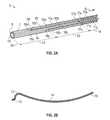
図2a及び図2bは、湾曲可能医用デバイス3の概略図である。図2aは、湾曲可能医用デバイス3の接写斜視図である。図2bは、湾曲可能医用デバイス3の湾曲可能セグメントを説明するための概略図である。湾曲可能医用デバイス3は、遠位端24及び近位端を有し(矢印Aの方向に)、近位部19と3つの湾曲可能セグメント(それぞれ第1、第2、第3の湾曲可能セグメント12,13,14である)を有する。 2a and 2b are schematic illustrations of a bendable
湾曲可能セグメント12,13,14は、図2bから分かるように、独立して湾曲することができ、3つの独立した曲率をもつ形状を形成することができる。湾曲可能医用デバイス3は、内径40及び外径42を有する湾曲可能体7を含み(図4Bを参照)、外径が湾曲可能体7の円筒状の壁8を形成し、内径によってツールチャネル18が設けられる(図4bを参照)。壁8は、制御ワイヤを収容することを目的とする複数のルーメン34を収容してよい(図11を参照)。ツールチャネル18は、湾曲可能体7の端から端まで延びるように構成され、湾曲可能体7の近位部19は、臨床ユーザに対して、医用ツールの挿入/後退のためのアクセスを提供する。例えば、臨床ユーザは、ツールチャネル18を通して、湾曲可能医用デバイス3の遠位端24まで生検ツールを挿入し、回収することができる。これは、湾曲可能デバイス3が患者に挿入された後、又は、湾曲可能デバイス3の挿入/後退と一致して、達成することができる。 The
湾曲可能体7は、第1の制御ワイヤ9a,9b,9cのセットと、制御ワイヤ10a,10b,10cの第2のセットと、制御ワイヤ11a,11b,11cの第3のセットとを含む。壁8は、ルーメン34内に、湾曲可能体7の長手方向に沿って構成された制御ワイヤ9a~11cを収容する。ルーメン34により、制御ワイヤ9a~11cは、湾曲可能体の軸方向に沿ってスライド可能に動くことができる。制御ワイヤ9a~11cは、各湾曲可能セグメント12,13,14の遠位端で終端されて、3つの湾曲可能グループを形成し、各々が3本のワイヤ(a,b,c)を含む。第1の制御ワイヤ9a,9b,9cは、第1の湾曲可能セグメント12の遠位端でアンカリング部15a,15b,15cによって終端され、壁8内で互いにおよそ120度離れて構成される。第1の制御ワイヤ9a,9b,9cは、ワイヤ9a,9b,9cの近位端で駆動ユニット2に接続される。駆動ユニット2は、制御ワイヤ9a,9b,9cを作動させ、遠位端24から湾曲可能体7を曲げることにより、当該ワイヤを動かすための押す力と引く力を誘発する。 The
同様に、制御ワイヤ10a,10b,10cの第2のセットは、第2の湾曲可能セグメント13の遠位端でアンカリング部16a,16b,16cを用いて終端され、近位端では駆動ユニット2に接続される。制御ワイヤ10a,10b,10cの第2のセットも、壁8内に収容される。制御ワイヤ10a,10b,10cの第2のセットは、第2の湾曲可能セグメント13の遠位端から湾曲可能体7を曲げることができる。 Similarly, a second set of
同様に、制御ワイヤ11a,11b,11cの第3のセットも、再度、駆動ユニット2によって制御ワイヤ11a,11b,11cの遠位端24で作動される押し又は引きを誘発することにより、第3の湾曲可能セグメント14で湾曲可能体7を曲げるように構成される。 Similarly, the third set of
したがって、制御ワイヤ9,10,11のセットを押し引きすることにより、第1、第2及び第3の湾曲可能セグメント12,13,14は、それぞれ、湾曲可能医用デバイス3を3つの次元で個別に曲げる。 Thus, by pushing and pulling the sets of
主題の湾曲可能医用デバイス3は、湾曲可能体の壁8内の最小の空間を用いて湾曲可能体7に固定することのできる制御ワイヤ9,10,11を包含する。アンカリング部15~17は個別のルーメン34内に局在するので、特に複数の制御ワイヤ9,10,11を用いる場合に、制御ワイヤ9,10,11を備える湾曲可能医用デバイス3を効果的に小型化することができる。更に、制御ワイヤ9,10,11は、湾曲可能体7の壁8内に完全に収容することができ、外径42の外側や内径40の内側にある必要はないので、ツールチャネル18に衝突したり、医用デバイス3の全体サイズを不必要に増大させたりすることがない。湾曲可能体7の壁8内にアンカー部15~17を埋め込むことにより、制御ワイヤ9,10,11は、押す力、トルク及び引く力を湾曲可能体7に伝達することができる。したがって、湾曲可能医用デバイス3は、引く力を用いる従来の腱駆動システムに比べて、制御ワイヤ9,10,11の数や、制御ワイヤ9,10,11あたりの力の負荷を低減して、目的の曲げ操縦を達成することができる。 The subject bendable
更に、アンカリング部15~17は、湾曲可能体7の断面をカバーする追加の当接部を必要としないので、湾曲可能医用デバイス3は、アンカリング部15~17の位置において、湾曲可能体7とそのような追加の当接部との間の接合点の数を減らすことができる。したがって、主題の湾曲可能医用デバイス3は、運動制御の影響を低減することで柔軟性の連続性を改善し、そのような接合点での故障のリスクを低減することができる。また、患者の生体構造への外傷のリスクを回避し、ツールチャネル18でのツールの前進/引戻しを改善するために、湾曲可能医用デバイス3は、湾曲可能体7の外径42及び内径40上に連続した滑らかな表面を有することができる。 Furthermore, since the anchoring parts 15-17 do not require additional abutments covering the cross-section of the
更に、制御ワイヤ9,10,11は、湾曲可能体7の長さに沿った様々な位置で湾曲可能体に固定することができるので、湾曲可能医用デバイス3は、患者の目的治療エリアへの柔軟なアクセスを改善するために、複数の湾曲セグメント、特に、湾曲可能体の近位部から独立して操作される遠位湾曲セグメントを有するように構成することができる。 In addition, the
図3aは、空洞に挿入された例示の湾曲可能医用デバイス3の切欠図を提供し、図3b及び図3cは、様々な向き/操縦のオプションを示す、例示の湾曲可能医用デバイス3の斜視図を提供する。 Figure 3a provides a cutaway view of an exemplary bendable
図3a、図3b及び図3cは、患者の肺の気管支周辺領域(気道周辺の側域である)における病変のナビゲーション及びターゲティングを例示する概略図である。このエリアは、従来のカテーテルの遠位での器用さが制限されるので、文献及び先行技術で特定されているように、ターゲットとなる既知の課題である。ナビゲーション段階では、気道22を通って病変に到達するために、第1及び第2の湾曲可能セグメント12,13は、それぞれ分岐点32を通して湾曲可能医用デバイス3をナビゲートする。分岐点32では、湾曲可能医用デバイス3が分岐点32を通って前進するにつれて、第1の湾曲可能セグメント12は娘枝に対して形状/向きを調整することができ、一方、第2の湾曲可能セグメント13は親枝に対して形状/向きを調整することができる。第1及び第2の湾曲可能セグメント12,13が分岐点32を通過すると、当該セグメントは、湾曲可能医用デバイス3の残りを導くガイドの役割を果たすことができるので、遠位セクションの深刻な逸脱を生じることなく、単一カテーテルの近位端からの挿入力を、単一カテーテルの遠位部への挿入力に効果的に変換することができる。湾曲可能医用デバイス3の遠位端24が病変の近くに到達すると、湾曲可能医用デバイス3は、第1及び第2の湾曲可能セグメント12,13をそれぞれ曲げることにより、遠位端24を病変23(気道周辺の側域を位置付ける)へ向けることになる。気道は病変23に直接つながっていないので、これは、従来のカテーテルにとってより難しい構成のひとつである。 Figures 3a, 3b and 3c are schematic diagrams illustrating the navigation and targeting of lesions in the peribronchial region (which is the area around the airways) of a patient's lungs. This area is a known target problem, as identified in the literature and prior art, as the distal dexterity of conventional catheters is limited. In the navigation phase, the first and second
第1、第2及び第3の湾曲可能セグメント12,13,14のそれぞれを用いて、湾曲可能医用デバイス3は、全ての分岐を通ってこの病変に至る近位部19を動かすことなく、遠位端24を方向付けることができる。第1及び第2の湾曲可能セグメント12,13の3次元に曲がる能力を用いることにより、湾曲可能医用デバイス3は、独特な操作を実行して、気管支周囲のターゲティングの能力を高めることができる(図3b、図3c)。更に、湾曲可能体7の軸方向に沿って第1、第2及び第3の制御ワイヤ9,10,11の間に異なる位置のアンカリング部15~17を包含することによって、制御ワイヤ9,10,11は湾曲可能体7の異なる位置にマッピングされるので、湾曲可能体7は、軸方向に沿って別々に湾曲物体として機能することができる。したがって、湾曲可能医用デバイス3は、蛇行進路を通した、対象とする病変への改善されたアクセスを提供することができる。また、湾曲可能医用デバイス3は、接合点のサイズ又は数を増大させることなく、軸方向に沿って異なる柔軟性をもつことができる。 Using the first, second and third
全方向指向の第1の操縦では(図3b)、第1の湾曲可能セグメント12は、湾曲可能医用デバイス3のいかなる部分も回転させることなく、効果的に回転することができる。この操縦は、病変23に対する遠位端の向きを決定するのに有益である。なぜなら、この運動は、生体構造に対するカテーテルの近位部の物理的相互作用の影響を受けず、また、遠位端24の向きを物理的にマッピングしている間に、病変23の位置に影響を与えないからである。更に、第2の湾曲可能セグメント13により、湾曲可能医用デバイス3は、この全方向指向を、最終分岐点を通過して病変23に到達した後に実行することができる。この回転中、湾曲可能医用デバイス3は、第2及び第3の湾曲可能セグメント13,14を動かすことなく、第1の湾曲可能セグメント12のみの湾曲面を回転させることができる。 In the omnidirectional first maneuver ( FIG. 3 b ), the first
第2の操縦は、図3cに示されるように、集落抽出である。第1の湾曲可能セグメント12は、遠位端の向きを維持しながら、遠位端の位置を変えることができる。この操縦により、遠位端は、病変23の異なる位置にアクセスすることができる。この操縦の利点は、病変23の異なる位置にアクセスできること、又は、遠位端の位置の細かい調整が実行できることである。湾曲可能医用デバイス3は、同一の向きで遠位端の位置を変えることができる。したがって、位置調整の分解能(及び正確性/精度)は、遠位端の位置変化に直接関連する。 The second maneuver is cluster extraction, as shown in Figure 3c. The first
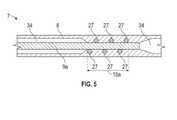
図4a、図4b、図4c及び図5は、アンカー部15~17の様々な構造を詳細に示す図である。図4aは、湾曲可能医用デバイス3の遠位端24の接写図である。この特定の実施形態では、湾曲可能体7は、ポリエーテルブロックアミドから成る管であり、外径が3mmであり、ツールチャネル18用に内径が2mmである。湾曲可能体7の縁は、非外傷性の先端26を形成するように丸みを帯びている。図4bは、図4aの線B-Bの断面図である。湾曲可能体7は、壁8内に、制御ワイヤ9a,9b,9c(この実施形態では、それぞれ直径が150ミクロンである)を部分的に収容するように構成された9つのルーメン34を含む。第1の制御ワイヤ9a,9b,9cは、湾曲体7の壁8を通り、第1の湾曲可能セグメント12の遠位端で終端される。 Figures 4a, 4b, 4c and 5 show in detail the various structures of the anchor parts 15-17. FIG. 4a is a close-up view of the
図4c及び図5は、図4aのボックスCの接写図である。具体的には、図5は、図4cの線D-Dでの断面図である。第1の制御ワイヤ9aは、アンカー要素21としてスパイラルコイル構造を含む。アンカー要素21は、第1の制御ワイヤ9aに固定される。この固定は、溶接、ろう付け及び/又は接着によって行うことができる。固定後、スパイラルコイル構造は、壁8に埋め込まれた突起要素27となる。スパイラルコイル構造をアンカー要素として用いることにより、ミニチュアサイズの突起要素21の高さ及びピッチの正確性を制御することができる。また、制御ワイヤとアンカー要素の組立てプロセスにおいてばねの復元力を利用することにより、セルフクランプ機能をもつことが有利である。更に、ワイヤの長手方向に沿ったこのような突起要素27は、1つの部品のみで作製することができる。突起要素27は、壁8に埋め込まれている(図5)。突起要素は、制御ワイヤの長手方向の長さに沿って展開するので、第1のアンカリング部15aも、第1の制御ワイヤ9aに沿って形成される。接続及び/又は取付けの強度を高めるために、アンカリング部15aの突起の長さ及び/又は高さを増大させることができる。第1のアンカリング部15aでは、第1の制御ワイヤ9aが湾曲可能体7によって拘束される。したがって、第1の制御ワイヤ9aは、押し引きの力及びトルクを湾曲可能体7に伝達して、第1の湾曲可能セグメント12を作動させることができる。当然のことながら、残りの制御ワイヤ10a~11cは、制御ワイヤ9a~9cとの共通の特性及び構成の類似点を共有する。 Figures 4c and 5 are close-up views of box C in Figure 4a. Specifically, FIG. 5 is a cross-sectional view along line DD of FIG. 4c. The
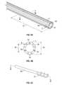
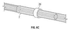
図6a、図6b、図6cは、湾曲体7の作製とアンカーセグメント15~17の埋込みのための製造プロセスを説明する。まず、第1の制御ワイヤ9a,9b,9cの指定の位置にアンカー要素21があるように、第1の制御ワイヤ9a,b,c及びアンカー要素21が組み立てられる(図6a)。アンカー要素21と組み立てられた第1の制御ワイヤ9a,9b,9cは、所望の位置で壁8の適切なルーメン34に挿入される。何も入っていない残りのルーメン34には、マンドレル28が挿入されてよい。また、ツールチャネル18には大きめのマンドレル28が挿入されてよい(図6b)。マンドレル28は、何も入っていないルーメン34及びツールチャネル18の構造的完全性及び寸法を保持するために挿入される。湾曲可能体7の壁8に突起要素27を埋め込むために、湾曲可能体7は、ヒーター29を用いて、アンカー要素21の周りのみ加熱/リフローされる(図6c)。加熱プロセスにより、アンカー要素21と湾曲可能体7/壁8との間に融合が形成される。融合は、1つ以上の物質が固体から液体へ相転移し、続いて1つ以上の物質を冷却し、それにより融合した1つ以上の物質を固体に戻す物理的プロセスによって、達成することができる。そのようなステップを通して、アンカー要素21は、業界標準のカテーテル製造ステップを用いて埋め込まれる。 Figures 6a, 6b, 6c illustrate the manufacturing process for making the
図7a、図7b、図7cは、アンカー要素21の様々な実施形態を示す。一実施形態は、アンカー要素21a,21bとしてビーズ及びディスクを採用する。ビーズ及びディスクを用いる場合、アンカリング部15~17は、同一の単位部品から異なる長さで作製することができる。他の実施形態は、アンカー要素21cとして板ばねを含むことができる。板ばねを用いる場合、突起要素の高さと、湾曲可能体7とアンカリング要素21cの間の取付け強度の両方を、増大させることができる。別の実施形態は、制御ワイヤ9のスパイラルコイル機能を採用してよい。この特徴を用いる場合、部品の数と、結合点の数と、組立てのステップ/時間とを削減することができる。 7a, 7b, 7c show various embodiments of the
図8a、図8b及び図8cは、例示の湾曲可能医用デバイス3の概略断面図である。この実施形態は、前の実施形態で詳述した単一アンカーシステムとは異なる、複数のアンカリング部15を備えた第1の制御ワイヤ9を含む。 8a, 8b and 8c are schematic cross-sectional views of an exemplary bendable
図8aでは、第1の制御ワイヤ9は、湾曲可能体7の長手方向に沿って複数のアンカリング部15を有する。反対側では、第2の制御ワイヤ10には、遠位端にアンカリング部16が配置される。作動ユニットは、制御ワイヤ9及び10に結合され、指示通りに湾曲可能体7を曲げることができる。第1の制御ワイヤ9が様々な点で湾曲可能体7に固定されることで、運動の自由度が制限されるので、第1の制御ワイヤ9の弾性特性は、湾曲可能体7の結果的な弾性特性として反映される。したがって、第1の制御ワイヤ9は、湾曲可能体7の弾性特性を変更することができる。弾性特性は、曲げ剛性、ねじり剛性及び軸剛性の主な要因となり得る。具体的には、湾曲可能体7がエラストマーのような柔らかい素材で作られる場合、第1の制御ワイヤ9は、軸剛性を高めることにより、軸方向での望ましくない収縮及び膨張を防ぐことができる。更に、アンカリング部15は1つのルーメン34の空間内に局在しているので、複数のアンカリング部15を備えるこのタイプの制御ワイヤ9は、湾曲体7の複数のルーメン34に配置することができ、よって、限られた空間で湾曲可能医用デバイス3に構造的完全性を劇的に付加することができる。 In FIG. 8 a the
図8bでは、第2の制御ワイヤ10は、同様に複数のアンカリング部16を有し、第1の制御ワイヤ9よりも長さが短い。この構成では、湾曲可能体7は、長手方向に沿って、様々な弾性特性をもつセグメントを有することができる。この特定の実施形態では、第1の制御ワイヤ9及び第2の制御ワイヤ10を含む近位セグメントは、第1の制御ワイヤ9のみを含む遠位セグメントよりも大きい曲げ剛性及びねじり剛性をもつので、近位端からの湾曲可能体7の押し性能及びトルク性能が改善される。 In FIG. 8 b the
更に、第1の制御ワイヤ9及び第2の制御ワイヤ10は、医用イメージングモダリティにおいて可視の材料で作ることができる。この特定の実施形態では、第1の制御ワイヤ9及び第2の制御ワイヤ10は、放射線不透過性であり、X線透視装置において可視である。したがって、臨床ユーザは、第1の制御ワイヤ9と第2の制御ワイヤ10の形状を、X線透視装置下では湾曲可能体7の代理形状として区別することができる。また、遠位セグメントは第1の制御ワイヤ9のみを含むので、臨床ユーザは、X線透視装置で遠位セグメントを近位セグメントと区別することができる。 Furthermore, the
図8cでは、第1の制御ワイヤ9は、機能的プローブとして更に機能してよい。この特定の実施形態では、第1の制御ワイヤ9は、照明付きの内視鏡カメラユニット30を備えた内視鏡カメラプローブを有する。複数のアンカリング部15により、内視鏡カメラユニット30と、内視鏡カメラユニット30用のハーネスケーブルは、壁8に埋め込まれる。具体的には、内視鏡カメラユニット30は、全ての運動の自由度で湾曲可能体7に固定されるので、臨床ユーザによる操作中、内視鏡カメラユニット30の運動は湾曲可能体7の運動と一致する。この機能により、ユーザには、操作に関する直感的な情報が提供され、システムには、湾曲可能体7と内視鏡カメラユニット30の間の一貫した座標管理が提供される。 In Figure 8c, the
別の実施形態では、一貫した座標管理を実施することができるように、第1の制御ワイヤ9は、電磁位置追跡センサ又は形状感知ファイバを含んでよく、これにより、センサシステム、医用画像及び標的/患者の間の座標のレジストレーションに利点がもたらされる。 In another embodiment, the
複数のアンカリング部を備えた制御ワイヤを有することにより、湾曲可能医用デバイスは、湾曲可能体の軸方向を通して、湾曲可能体にあらゆる運動の自由度で固定された制御ワイヤを含むことができる。この特別な制御ワイヤは、湾曲可能体が曲げ、ねじり及び/又は並進の運動をしている間、制御ワイヤと湾曲可能体の間の幾何学的関係(すなわち位置及び向き)を維持することができる。したがって、制御ワイヤは、その機械特性を、そのような制約をもつ湾曲可能医用デバイスの結果的な機械特性に効果的に反映させることができ、湾曲可能医用デバイスの機械特性を変更することができる。具体的には、制御ワイヤの座屈のリスクを低減しながら、制御ワイヤの軸方向の機械的剛性を理想的に反映させることができる。 By having control wires with multiple anchoring portions, the bendable medical device can include control wires that pass axially through the bendable body and are fixed to the bendable body in all degrees of freedom of movement. This special control wire is capable of maintaining the geometric relationship (i.e., position and orientation) between the control wire and the bendable body while the bendable body undergoes bending, twisting and/or translational movements. can. Thus, the control wire can effectively reflect its mechanical properties into the resulting mechanical properties of the bendable medical device with such constraints, and can change the mechanical properties of the bendable medical device. . Specifically, the axial mechanical stiffness of the control wire can be ideally reflected while reducing the risk of buckling of the control wire.
更に、制御ワイヤは、湾曲可能体に対する幾何学的関係の一貫性を活用することにより、湾曲可能体の先端の位置及び向きを特定するための感知要素として利用することができる。 Additionally, the control wires can be utilized as sensing elements to determine the position and orientation of the tip of the bendable body by exploiting the consistency of the geometric relationship to the bendable body.
アンカリング部は1つのルーメン34の空間内に局在化しているので、湾曲可能体7は、複数の異なる機能的プローブを同時に有することができる。例えば、湾曲可能体7は、電磁位置追跡センサ及び内視鏡カメラユニットを含んでよく、内視鏡ビューの位置及び向きをリアルタイムで測定することができる。 Since the anchoring portion is localized within the space of one
追加の利点を認識することができるのは、第1及び第2の湾曲可能セグメントを湾曲可能体の遠位端からある距離に配置することで、遠位の器用さを高めた場合である。第1及び第2の湾曲可能セグメントは、カテーテルの遠位端の向きを変更するとともに、遠位端の位置を3次元で変更するために、独立して調整/操作することができる。両セクションが同じ平面で動く必要はない。このような運動により、カテーテルの遠位端は、3つの湾曲可能セグメントを用いて、様々な向きから様々な位置にアクセスすることができる。したがって、湾曲可能医用デバイスにより、医師には、生検鉗子や微細吸引針、アブレーションプローブ等の医用器具のアクセスに関して、より幅広い対処可能なエリアとアプローチが提供される。 An additional advantage can be appreciated if the first and second bendable segments are positioned a distance from the distal end of the bendable body to enhance distal dexterity. The first and second bendable segments can be independently adjusted/manipulated to change the orientation of the distal end of the catheter as well as change the position of the distal end in three dimensions. Both sections need not move in the same plane. Such motion allows the distal end of the catheter to access different locations from different orientations using the three bendable segments. Bendable medical devices therefore provide physicians with a wider addressable area and approach for accessing medical instruments such as biopsy forceps, fine aspiration needles, and ablation probes.
また、第3の湾曲可能セグメントは、外力によって変形して、生体構造にかかる力を最小限に抑えながら、肺の気道や血管、脳室等の生体構造の蛇行経路の形状に従うことができる。したがって、生体構造の形状に従うことにより、第3の湾曲可能セグメントは、カテーテルが挿入されたときに第1及び第2の湾曲可能セクションによってナビゲートすることができ、医療処置用の医用器具と制御のための駆動力との両方の送達ラインを進展させることができる。 The third bendable segment can also be deformed by an external force to follow the shape of the tortuous path of the anatomy, such as the airways and blood vessels of the lungs, ventricles, etc., while minimizing forces on the anatomy. Thus, by following the shape of the anatomy, the third bendable segment can be navigated by the first and second bendable sections when the catheter is inserted, providing medical instruments and controls for medical procedures. Both the driving force for and the delivery line can be advanced.
更に、湾曲可能医用デバイスは、第1及び第2の湾曲可能セグメントを有することにより、一貫した正確な遠位操縦を提供する。第2の湾曲可能セグメントは、第1の湾曲可能セグメントの運動を、湾曲可能医用デバイスの近位部の他の部分から切り離す。第2の湾曲する湾曲可能セグメントを含むカテーテルの近位部は、生体構造の蛇行経路を通過し、経路に沿った多くの接触を伴って生体構造と相互作用するので、そのような接触により、カテーテルの運動が妨げられ、カテーテルの制御精度が劣化してしまう。更に、接触点と接触の程度は患者の動きと湾曲可能医用デバイスの操縦によって変化するので、このような劣化自体は、体系的ではなくランダムである。したがって、第1及び第2の湾曲可能セグメントを切り離すことにより、湾曲可能医用デバイスは、制御の劣化を防止し、一貫した正確な遠位操縦を達成することができる。 Further, the bendable medical device provides consistent and precise distal steering by having first and second bendable segments. The second bendable segment decouples motion of the first bendable segment from other portions of the proximal portion of the bendable medical device. As the proximal portion of the catheter, including the second curving bendable segment, passes through a tortuous path of the anatomy and interacts with the anatomy with many contacts along the path, such contacts Catheter movement is hampered and catheter control accuracy is compromised. Moreover, such degradation itself is random rather than systematic, as the contact points and degree of contact vary with patient movement and maneuvering of the bendable medical device. Thus, by decoupling the first and second bendable segments, the bendable medical device can prevent deterioration of control and achieve consistent and precise distal steering.
最後に、湾曲可能体は、第1の制御ワイヤの軸剛性を反映することによって曲げ運動の制御不能な収縮及び拡張を回避することができるので、湾曲可能医用デバイスは、曲げの制御の正確性を改善し、異なる湾曲セグメントの間のクロストークを低減することができる。 Finally, since the bendable body can avoid uncontrolled contraction and expansion of the bending motion by mirroring the axial stiffness of the first control wire, the bendable medical device can improve the accuracy of controlled bending. can be improved and crosstalk between different curved segments can be reduced.
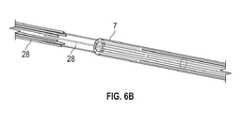
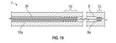
図9a、図9b、図9c及び図10に詳細に示された本革新の更に追加の実施形態では、図は、入れ子状の制御ワイヤを特徴とする例示の湾曲可能医用デバイス3を示す。図9aは、湾曲可能体7の長手方向に沿う中心軸を有する湾曲可能医用デバイス3の概略断面図である。図9b及び図9cは、それぞれ線E-Eと線G-Gでの概略切欠断面図である。第1の制御ワイヤ9a,9bは、それぞれ第2の制御ワイヤ10a,10bに入れ子になっており、第1の制御ワイヤ9a,9bは、第2の制御ワイヤ10a,10b内でスライド可能である。図10は、図9aのボックス“F”の接写図である。第2の制御ワイヤ10は、第1の制御ワイヤ9と同じルーメン34に構成される。更に、より大きな駆動力に対応するために、第2のアンカリング部16は第1のアンカリング部15よりも長い。 In yet a further embodiment of the present innovation detailed in Figures 9a, 9b, 9c and 10, the figures show an exemplary bendable
この構成を用いる場合、第2の制御ワイヤ10は第1の制御ワイヤ9と同じ軸及び空間を共有するので、第2の制御ワイヤ10は、湾曲可能体7の他の構造を通過することなく、第2の制御ワイヤ10の間隔において第1の制御ワイヤ9の押し引き力を相殺することができる。例えば、遠位端を曲げるために第1の制御ワイヤ9が引かれたとき、第2の制御ワイヤ10は、近位部の形状を維持するために、同じ大きさの力で押されてよい。更に、第1の制御ワイヤ9は第2の制御ワイヤ10内に入れ子になっているので、それら2本の制御ワイヤの軸は、湾曲可能体7が経路に沿って曲げられたときでも一貫性を保つことになる。したがって、湾曲可能医用デバイス3は、臨床操作中の異なる湾曲可能セグメント間のクロストークを効果的に低減することができる。特に、湾曲可能体の軸剛性が比較的低く、駆動力なしで平面から断面を歪める可能性がある場合、第2の制御ワイヤは、第1の制御ワイヤにかかる軸方向の駆動力を相殺することによって、第2の制御ワイヤの間隔においてこのような歪みを補償することができる。 With this configuration, the
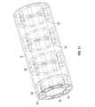
図11及び図12は、例示の湾曲可能医用デバイスの側面3次元斜視図を示す。湾曲可能医用デバイス3は、湾曲可能体7の内径40及び外径42の内側に収容された少なくとも2つのワイヤガイド36を含み、ワイヤガイド36は、互いに距離を置いて構成され、互いに接触しない。湾曲可能体7は、インナーライニング44及びアウターライニング46を有し、これにより、湾曲可能体7の軸方向に沿ってワイヤガイド36を一定の位置に保持しながら、湾曲可能体7に湾曲可能な支持を提供する。各ワイヤガイド36は、制御ワイヤ9a~11cをスライド可能に収容するための少なくとも2つのルーメン34を含み、ワイヤガイド36に埋め込まれるアンカー部(図示なし)を収容するように構成される。隣接するワイヤガイド間の空間は、弾力のあるインナーライニング44及びアウターライニング46と協働して、ワイヤガイド36間の開放空間によって湾曲可能体7がより大きな範囲の曲げ運動を達成することを可能にする。 11 and 12 show side three-dimensional perspective views of an exemplary bendable medical device. The bendable
更に、個別のセクションと連続的なアウターライニング46のこの構成は、患者の生体構造に対応するように、ナビゲーションに必要となる所要の柔軟性に合わせて調整することができる。更に、この実施形態により、制御ワイヤ9は、ワイヤガイド36において湾曲可能体7に固定することができる。 Moreover, this configuration of discrete sections and continuous
図12は、少なくとも2つのワイヤガイド36と併せた、入れ子状の制御ワイヤ9(図9a~図10と併せて論じられた)の使用を更に示す。 FIG. 12 further illustrates the use of nested control wires 9 (discussed in conjunction with FIGS. 9a-10) in conjunction with at least two wire guides 36. FIG.
Claims (14)
Translated fromJapanese前記壁内にスライド可能に位置する少なくとも1つの制御ワイヤと、
前記少なくとも1つの制御ワイヤの遠位端に構成されたアンカーと、
を備える医用装置であって、
前記アンカーは前記壁内に固定され、
前記アンカーは、前記壁に埋め込まれるように構成された少なくとも1つの突起要素を備え、前記制御ワイヤの軸方向に沿って延びる、
医用装置。a bendable body having a cavity extending the length of the bendable body and a wall formed around the cavity;
at least one control wire slidably positioned within the wall;
an anchor configured at a distal end of the at least one control wire;
A medical device comprising:
the anchor is secured within the wall;
the anchor comprises at least one protruding element configured to be embedded in the wall and extending along the axial direction of the control wire;
medical device.
請求項1に記載の医用装置。said protruding elements are selected from the group consisting of beads, discs, leaf springs, spiral coils, derivatives thereof and combinations thereof;
A medical device according to claim1 .
請求項1に記載の医用装置。the wall has at least one lumen for slidably housing the at least one control wire;
A medical device according to claim 1 .
を更に備え、
第1の前記制御ワイヤ及び第2の前記制御ワイヤの前記アンカーの位置は、前記湾曲可能体の軸方向に沿って異なる、
請求項1に記載の医用装置。a second control wire slidably positioned within the wall, the second control wire having an anchor for securing the second control wire to the wall;
further comprising
the positions of the anchors of the first control wire and the second control wire are different along the axial direction of the bendable body;
A medical device according to claim 1 .
請求項1に記載の医用装置。the at least one control wire includes a first anchor and a second anchor, the positions of the first anchor and the second anchor differing along an axial direction of the bendable body;
A medical device according to claim 1 .
請求項1に記載の医用装置。further comprising a drive unit in communication with the at least one control wire and configured to actuate the at least one control wire within the wall;
A medical device according to claim 1 .
請求項1に記載の医用装置。the at least one control wire further comprising an outer wire and an inner wire, the inner wire slidably nested within the outer wire;
A medical device according to claim 1 .
請求項7に記載の医用装置。the outer wire has an anchor for fixing the outer wire to the wall; the inner wire has an anchor for fixing the inner wire to the wall; the positions of the anchors are different along the axial direction of the bendable body;
8. A medical device according to claim7 .
請求項1に記載の医用装置。the control wire and the anchor are made of a radiopaque material;
A medical device according to claim 1 .
請求項1に記載の医用装置。further comprising a functional probe selected from the group consisting of a position tracking sensor, a shape sensor, an endoscopic imaging probe, derivatives thereof and combinations thereof;
A medical device according to claim 1 .
請求項10に記載の医用装置。said functional probe is selected from the group consisting of said anchor, control wire, derivatives thereof and combinations thereof;
11. A medical device according to claim10 .
請求項1に記載の医用装置。securing the anchor to the wall includes heating the wall and the anchor to form a heat fusion;
A medical device according to claim 1 .
請求項1に記載の医用装置。the wall comprises at least two wire guides, the wire guides being spaced apart from each other;
A medical device according to claim 1 .
前記医用装置は、
前記壁内に構成された前記アンカーを加熱して、前記湾曲可能体と前記アンカーの間に融合を形成するステップと、
前記壁内に構成された前記アンカーを冷却して、前記融合を固めるステップと、
を含むプロセスによって製造され、
前記アンカーは、前記壁に埋め込まれるように構成された少なくとも1つの突起要素を備え、前記制御ワイヤの軸方向に沿って延びる、
医用装置。A medical device comprising a bendable body, the bendable body having a cavity extending the length of the bendable body, a wall formed around the cavity, and slidably positioned within the wall. at least one control wire and an anchor configured at a distal end of the at least one control wire;
The medical device comprises:
heating the anchor configured within the wall to form a fusion between the bendable body and the anchor;
cooling the anchor configured in the wall to harden the fusion;
Manufactured bya process that includes
said anchor comprises at least one protruding element configured to be embedded in said wall and extending along the axial direction of said control wire;
medical device.
Applications Claiming Priority (3)
| Application Number | Priority Date | Filing Date | Title |
|---|---|---|---|
| US201862750641P | 2018-10-25 | 2018-10-25 | |
| US62/750,641 | 2018-10-25 | ||
| PCT/US2019/057711WO2020086749A1 (en) | 2018-10-25 | 2019-10-23 | Medical apparatus with reflow trapped anchors and method of use thereof |
Publications (2)
| Publication Number | Publication Date |
|---|---|
| JP2022505596A JP2022505596A (en) | 2022-01-14 |
| JP7128963B2true JP7128963B2 (en) | 2022-08-31 |
Family
ID=70330390
Family Applications (1)
| Application Number | Title | Priority Date | Filing Date |
|---|---|---|---|
| JP2021521994AActiveJP7128963B2 (en) | 2018-10-25 | 2019-10-23 | Medical device with reflow trap anchor and method of use thereof |
Country Status (3)
| Country | Link |
|---|---|
| US (1) | US20210386972A1 (en) |
| JP (1) | JP7128963B2 (en) |
| WO (1) | WO2020086749A1 (en) |
Families Citing this family (7)
| Publication number | Priority date | Publication date | Assignee | Title |
|---|---|---|---|---|
| US11730551B2 (en) | 2020-02-24 | 2023-08-22 | Canon U.S.A., Inc. | Steerable medical device with strain relief elements |
| US12042121B2 (en) | 2020-12-29 | 2024-07-23 | Canon U.S.A., Inc. | Medical system with medical device overlay display |
| US12427276B2 (en) | 2021-04-16 | 2025-09-30 | Canon U.S.A., Inc. | Medical system with separator device |
| US12426957B2 (en) | 2021-07-07 | 2025-09-30 | Canon U.S.A., Inc. | Bendable medical device with multiple position sensors |
| US20250001133A1 (en)* | 2023-06-30 | 2025-01-02 | Boston Scientific Scimed, Inc. | Steerable catheter with push ring assembly |
| WO2025043186A1 (en)* | 2023-08-23 | 2025-02-27 | Canon U.S.A., Inc. | Insulated clamp rod for steerable catheter |
| CN119184768B (en)* | 2024-09-25 | 2025-04-11 | 江苏省肿瘤医院 | Minimally invasive surgery modular deformable suture needle and its morphology control method |
Citations (6)
| Publication number | Priority date | Publication date | Assignee | Title |
|---|---|---|---|---|
| US20020177766A1 (en) | 1999-09-21 | 2002-11-28 | Jamil Mogul | Steerable diagnostic catheters |
| JP2002360704A (en) | 2001-04-30 | 2002-12-17 | Biosense Webster Inc | Asymmetric catheter operable in two directions |
| US20070225701A1 (en) | 2006-03-10 | 2007-09-27 | O'sullivan Martin F | Esophagus isolation device |
| JP2015163128A (en) | 2014-02-28 | 2015-09-10 | 日本ゼオン株式会社 | Manufacturing method of distal-deflecting movable catheter, manufacturing method of wired ring, and jig for manufacturing wired ring |
| JP2016538031A (en) | 2013-10-25 | 2016-12-08 | インテュイティブ サージカル オペレーションズ, インコーポレイテッド | Flexible instrument with grooved steerable tube |
| WO2017155892A1 (en) | 2016-03-10 | 2017-09-14 | Medtronic Vascular Inc. | Steerable catheter with multiple bending radii via a steering mechanism with telescoping tubular components |
Family Cites Families (11)
| Publication number | Priority date | Publication date | Assignee | Title |
|---|---|---|---|---|
| GB8413058D0 (en)* | 1984-05-22 | 1984-06-27 | Minvade Ltd | Endoscopes |
| JPH05154091A (en)* | 1991-12-09 | 1993-06-22 | Olympus Optical Co Ltd | Flexible pipe apparatus |
| US5368564A (en)* | 1992-12-23 | 1994-11-29 | Angeion Corporation | Steerable catheter |
| US7637905B2 (en)* | 2003-01-15 | 2009-12-29 | Usgi Medical, Inc. | Endoluminal tool deployment system |
| US6837846B2 (en)* | 2000-04-03 | 2005-01-04 | Neo Guide Systems, Inc. | Endoscope having a guide tube |
| JP6430831B2 (en)* | 2011-10-14 | 2018-11-28 | インテュイティブ サージカル オペレーションズ, インコーポレイテッド | Catheter system |
| US8702647B2 (en)* | 2012-04-19 | 2014-04-22 | Medtronic Ablation Frontiers Llc | Catheter deflection anchor |
| US11273290B2 (en)* | 2014-09-10 | 2022-03-15 | Intuitive Surgical Operations, Inc. | Flexible instrument with nested conduits |
| JP6336230B1 (en)* | 2016-08-19 | 2018-06-06 | オリンパス株式会社 | Endoscope |
| PT3554424T (en)* | 2016-12-16 | 2023-04-03 | Edwards Lifesciences Corp | Deployment systems, tools, and methods for delivering an anchoring device for a prosthetic valve |
| US10543048B2 (en)* | 2016-12-28 | 2020-01-28 | Auris Health, Inc. | Flexible instrument insertion using an adaptive insertion force threshold |
- 2019
- 2019-10-23JPJP2021521994Apatent/JP7128963B2/enactiveActive
- 2019-10-23WOPCT/US2019/057711patent/WO2020086749A1/ennot_activeCeased
- 2019-10-23USUS17/286,397patent/US20210386972A1/enactivePending
Patent Citations (6)
| Publication number | Priority date | Publication date | Assignee | Title |
|---|---|---|---|---|
| US20020177766A1 (en) | 1999-09-21 | 2002-11-28 | Jamil Mogul | Steerable diagnostic catheters |
| JP2002360704A (en) | 2001-04-30 | 2002-12-17 | Biosense Webster Inc | Asymmetric catheter operable in two directions |
| US20070225701A1 (en) | 2006-03-10 | 2007-09-27 | O'sullivan Martin F | Esophagus isolation device |
| JP2016538031A (en) | 2013-10-25 | 2016-12-08 | インテュイティブ サージカル オペレーションズ, インコーポレイテッド | Flexible instrument with grooved steerable tube |
| JP2015163128A (en) | 2014-02-28 | 2015-09-10 | 日本ゼオン株式会社 | Manufacturing method of distal-deflecting movable catheter, manufacturing method of wired ring, and jig for manufacturing wired ring |
| WO2017155892A1 (en) | 2016-03-10 | 2017-09-14 | Medtronic Vascular Inc. | Steerable catheter with multiple bending radii via a steering mechanism with telescoping tubular components |
Also Published As
| Publication number | Publication date |
|---|---|
| US20210386972A1 (en) | 2021-12-16 |
| JP2022505596A (en) | 2022-01-14 |
| WO2020086749A1 (en) | 2020-04-30 |
Similar Documents
| Publication | Publication Date | Title |
|---|---|---|
| JP7128963B2 (en) | Medical device with reflow trap anchor and method of use thereof | |
| US20190105468A1 (en) | Medical continuum robot with multiple bendable sections | |
| JP7305668B2 (en) | Medical device with variable bending stiffness profile | |
| JP7232051B2 (en) | Image-guided robot for catheter placement | |
| JP7487363B2 (en) | Medical device having distributed cavities and method of use thereof - Patents.com | |
| JP6656148B2 (en) | System and associated method for robot-assisted endoluminal surgery | |
| JP7441810B2 (en) | Medical device with dual operating means and method of use thereof | |
| US6468203B2 (en) | Steerable endoscope and improved method of insertion | |
| CN107184272A (en) | Composite curve formula catheter navigation | |
| CN114828932B (en) | Medical device with segmented bendable section | |
| JP2011525827A (en) | Nested cannula for minimally invasive surgery | |
| JP7510508B2 (en) | Method and system for catheter target locking - Patents.com | |
| JP7381522B2 (en) | Medical device and its operating method | |
| US20250161632A1 (en) | Medical apparatus with wire anchors and method of use thereof | |
| US12042121B2 (en) | Medical system with medical device overlay display | |
| US20230137954A1 (en) | Medical robot having multiple manipulation means and methods of use thereof | |
| WO2025015163A2 (en) | Systems and methods for flexible medical device articulation |
Legal Events
| Date | Code | Title | Description |
|---|---|---|---|
| A521 | Request for written amendment filed | Free format text:JAPANESE INTERMEDIATE CODE: A523 Effective date:20210622 | |
| A621 | Written request for application examination | Free format text:JAPANESE INTERMEDIATE CODE: A621 Effective date:20210622 | |
| A977 | Report on retrieval | Free format text:JAPANESE INTERMEDIATE CODE: A971007 Effective date:20220415 | |
| A131 | Notification of reasons for refusal | Free format text:JAPANESE INTERMEDIATE CODE: A131 Effective date:20220426 | |
| A521 | Request for written amendment filed | Free format text:JAPANESE INTERMEDIATE CODE: A523 Effective date:20220712 | |
| TRDD | Decision of grant or rejection written | ||
| A01 | Written decision to grant a patent or to grant a registration (utility model) | Free format text:JAPANESE INTERMEDIATE CODE: A01 Effective date:20220802 | |
| A61 | First payment of annual fees (during grant procedure) | Free format text:JAPANESE INTERMEDIATE CODE: A61 Effective date:20220819 | |
| R150 | Certificate of patent or registration of utility model | Ref document number:7128963 Country of ref document:JP Free format text:JAPANESE INTERMEDIATE CODE: R150 | |
| R250 | Receipt of annual fees | Free format text:JAPANESE INTERMEDIATE CODE: R250 |