JP7127362B2 - ROBOT CONTROL DEVICE, CONTROL METHOD OF ROBOT CONTROL DEVICE, AND ROBOT SYSTEM - Google Patents
ROBOT CONTROL DEVICE, CONTROL METHOD OF ROBOT CONTROL DEVICE, AND ROBOT SYSTEMDownload PDFInfo
- Publication number
- JP7127362B2 JP7127362B2JP2018097311AJP2018097311AJP7127362B2JP 7127362 B2JP7127362 B2JP 7127362B2JP 2018097311 AJP2018097311 AJP 2018097311AJP 2018097311 AJP2018097311 AJP 2018097311AJP 7127362 B2JP7127362 B2JP 7127362B2
- Authority
- JP
- Japan
- Prior art keywords
- finger
- robot
- output
- detection unit
- control device
- Prior art date
- Legal status (The legal status is an assumption and is not a legal conclusion. Google has not performed a legal analysis and makes no representation as to the accuracy of the status listed.)
- Active
Links
- 238000000034methodMethods0.000titleclaimsdescription33
- 238000001514detection methodMethods0.000claimsdescription200
- 230000033001locomotionEffects0.000claimsdescription77
- 230000009471actionEffects0.000claimsdescription73
- 230000008569processEffects0.000claimsdescription26
- 239000012636effectorSubstances0.000description83
- 238000010586diagramMethods0.000description25
- 238000012545processingMethods0.000description21
- 238000004891communicationMethods0.000description14
- 230000005484gravityEffects0.000description12
- 210000000078clawAnatomy0.000description9
- 239000013078crystalSubstances0.000description9
- 230000006835compressionEffects0.000description7
- 238000007906compressionMethods0.000description7
- 239000000463materialSubstances0.000description7
- 230000008859changeEffects0.000description6
- XEEYBQQBJWHFJM-UHFFFAOYSA-NIronChemical compound[Fe]XEEYBQQBJWHFJM-UHFFFAOYSA-N0.000description4
- 230000005540biological transmissionEffects0.000description4
- 230000007423decreaseEffects0.000description4
- 230000006870functionEffects0.000description4
- 230000003287optical effectEffects0.000description4
- 238000013459approachMethods0.000description3
- 238000003384imaging methodMethods0.000description2
- 229910052742ironInorganic materials0.000description2
- 238000012986modificationMethods0.000description2
- 230000004048modificationEffects0.000description2
- 239000011347resinSubstances0.000description2
- 229920005989resinPolymers0.000description2
- 230000006866deteriorationEffects0.000description1
- 230000002542deteriorative effectEffects0.000description1
- 238000005516engineering processMethods0.000description1
- 230000007613environmental effectEffects0.000description1
- 238000002474experimental methodMethods0.000description1
- 230000010365information processingEffects0.000description1
- 230000010354integrationEffects0.000description1
- 230000002093peripheral effectEffects0.000description1
- 238000003825pressingMethods0.000description1
- 238000012827research and developmentMethods0.000description1
- 230000004044responseEffects0.000description1
- 239000007787solidSubstances0.000description1
- 238000012360testing methodMethods0.000description1
- 230000007704transitionEffects0.000description1
Images


Landscapes
- Manipulator (AREA)
Description
Translated fromJapaneseこの発明は、ロボット制御装置、ロボット制御装置の制御方法、及びロボットシステムに関する。The present invention relates to a robot control device,a control method for a robot control device, and a robot system.
ロボットによる物体の把持に関する技術の研究や開発が行われている。 Research and development of technology related to gripping of objects by robots are being conducted.
これに関し、サーボモーターによって駆動される2つの爪をアーム先端に備え、2つの爪によって物体を把持し、2つの爪を駆動しているサーボモーターの電流値を用いて、物体を把持した状態における2つの爪の相対位置を検出し、検出した当該相対位置に基づいて物体の寸法が予め決められた寸法であるか否かを判定し、判定した結果に応じた動作を行うロボットが知られている(特許文献1参照)。 In this regard, two claws driven by a servomotor are provided at the tip of the arm, the object is gripped by the two claws, and the current value of the servomotor driving the two claws is used to grasp the object. 2. Description of the Related Art There is known a robot that detects the relative positions of two claws, determines whether or not the dimensions of an object are predetermined based on the detected relative positions, and performs an action according to the determined result. (See Patent Document 1).
ここで、複数の爪を駆動するサーボモーターの電流値は、複数の爪によって物体が把持されている場合における複数の爪と物体との相対的な位置関係に応じて変化してしまう場合がある。例えば、複数の爪の先端間によって物体が把持された場合と、複数の爪の根本間によって物体が把持された場合とでは、当該サーボモーターに加わる負荷の違いが異なり、当該サーボモーターの電流値の違いが大きくなってしまう。その結果、ロボットは、把持したか否かの判定がばらつくため、物体の寸法が予め決められた寸法であるか否かを精度よく判定することができない場合があった。 Here, the current value of the servo motor that drives the multiple claws may change according to the relative positional relationship between the multiple claws and the object when the object is gripped by the multiple claws. . For example, when an object is gripped between the tips of a plurality of claws and when an object is gripped between the bases of a plurality of claws, the difference in the load applied to the servomotor is different, and the current value of the servomotor is difference becomes large. As a result, the robot may not be able to accurately determine whether or not the dimensions of the object are the predetermined dimensions, because the determination of whether or not the robot has grasped the object varies.
上記課題を解決するために本発明の一態様は、基部と、前記基部に対して移動可能に設けられた第1指部と、前記基部に設けられた第2指部と、前記基部に対する前記第1指部の位置を検出する第1位置検出部と、を有する把持部と、アームと、前記把持部と前記アームとの間に設けられた力検出部と、を備えたロボットを制御するロボット制御装置であって、前記第1指部を物体に接触させ、前記力検出部から出力される出力値が第1閾値以上となるまで前記第1指部を前記物体に付勢させる第1動作を行わせ、前記第1動作の後、前記力検出部から出力される出力値が前記第1閾値以上である状態を維持し、前記第1指部と前記アームとを移動させ、前記物体に前記第1指部と前記第2指部とを接触させる第2動作を行わせ、前記第2動作において、前記力検出部から出力される出力値が前記第1閾値よりも小さい第2閾値よりも小さくなったとき、前記第1位置検出部から出力される出力値に基づいて、前記物体が所定の状態で前記第1指部と前記第2指部とによって把持されているか否かを判定する、ロボット制御装置である。In order to solve the above problems, one aspect of the present invention provides a base, a first finger provided movably with respect to the base, a second finger provided at the base, and the A robot comprising: a gripping section having a first position detecting section for detecting a position of a first finger; an arm; and a force detecting section provided between the gripping section and the arm In the robot control device, the first finger is brought into contact with an object, and the first finger is urged against the object until the output value output from the force detection unit becomes equal to or greater than afirst threshold. After the first action, the output value output from the force detection unit is maintained equal to or greater than the first threshold value, the first finger and the arm are moved, and the object is perform a second action of bringing the first finger and the second finger into contact with each other, and in the second action, the output value output from the force detecting section issmaller than the first threshold value. When the value is smaller than the threshold value,whether or not the object is gripped by the first finger and the second finger in a predetermined state is determinedbased on the output value output from the first position detection unit. It is a robot control devicethat determines whether
また、本発明の一態様は、基部と、前記基部に対して移動可能に設けられた第1指部と、前記基部に設けられた第2指部と、前記基部に対する前記第1指部の位置を検出する第1位置検出部と、を有する把持部と、アームと、前記把持部と前記アームとの間に設けられた力検出部と、を備えたロボットを制御するロボット制御装置の制御方法であって、前記第1指部を物体に接触させ、前記力検出部から出力される出力値が第1閾値以上となるまで前記第1指部を前記物体に付勢させる第1動作と、前記第1動作の後、前記力検出部から出力される出力値が前記第1閾値以上である状態を維持し、前記第1指部と前記アームとを移動させ、前記物体に前記第1指部と前記第2指部とを接触させる第2動作と、前記第2動作において、前記力検出部から出力される出力値が前記第1閾値よりも小さい第2閾値よりも小さくなったとき、前記第1位置検出部から出力される出力値に基づいて、前記物体が所定の状態で前記第1指部と前記第2指部とによって把持されているか否かを判定する処理と、を有するロボット制御装置の制御方法である。Further, according to one aspect of the present invention, a base portion, a first finger portion movably provided with respect to the base portion, a second finger portion provided at the base portion, and a position of the first finger portion with respect to the base portionControl of a robot control device for controlling a robot comprising a gripping section having a first position detecting section for detecting a position, an arm, and a force detecting section provided between the gripping section and the arm a first action of contacting the first finger with anobject and urging the first finger against the object until an output value output from the force detection unit is greater than or equalto a first threshold value; , after the first action, the state in which the output value output from the force detection unit is equal to or greater than the first threshold is maintained, the first finger and the arm are moved, and the object is moved to the first A second action of bringing the finger into contact with the second finger,and in the second action, the output value output from the force detection unit is smaller than a second threshold that issmaller than the first threshold determiningwhether or not the object is gripped by the first finger and the second finger in a predetermined statebased on the output value output from the first position detection unit; and a control method fora robotcontrol device .
また、本発明の一態様は、基部と、前記基部に対して移動可能に設けられた第1指部と、前記基部に設けられた第2指部と、前記基部に対する前記第1指部の位置を検出する第1位置検出部と、を有する把持部と、アームと、前記把持部と前記アームとの間に設けられた力検出部と、を備えたロボットと、前記ロボットを制御するロボット制御装置と、を備えたロボットシステムであって、前記ロボット制御装置は、前記第1指部を物体に接触させ、前記力検出部から出力される出力値が第1閾値以上となるまで前記第1指部を前記物体に付勢させる第1動作を行わせ、前記第1動作の後、前記力検出部から出力される出力値が前記第1閾値以上である状態を維持し、前記第1指部と前記アームとを移動させ、前記物体に前記第1指部と前記第2指部とを接触させる第2動作を行わせ、前記第2動作において、前記力検出部から出力される出力値が前記第1閾値よりも小さい第2閾値よりも小さくなったとき、前記第1位置検出部から出力される出力値に基づいて、前記物体が所定の状態で前記第1指部と前記第2指部とによって把持されているか否かを判定する、ロボットシステムである。
Further, according to one aspect of the present invention, a base portion, a first finger portion movably provided with respect to the base portion, a second finger portion provided at the base portion, and a position of the first finger portion with respect to the base portion A robot comprising: a gripping section having a first position detecting section for detecting a position; an arm; and a force detecting section provided between the gripping section and the arm; and a robot for controlling the robot. and a controller, wherein the robot controller brings the first finger into contact with an object, and controls the first finger until an output value output from the force detection unit becomes equalto or greater than a first threshold. performing a first action of urging one finger toward the object; after the first action, maintaining a state in which the output value output from the force detection unit is equal to or greater than the first threshold; moving the fingers and the arm to perform a second action of bringing the first finger and the second finger into contact with the object, and outputting an output from the force detection section in the second action When the value becomes smaller than a second threshold valuesmaller than the first threshold value, the object is in a predetermined statebased on the output value output from the first position detection unit, and the first finger and the A robot systemfor determining whether or not an object is being grasped by a second finger.
<実施形態>
以下、本発明の実施形態について、図面を参照して説明する。なお、本実施形態における長さの単位は、如何なる単位であってもよい。以下では、一例として、本実施形態における長さの単位が、ミリメートルである場合について説明する。このため、以下では、長さを表す数値、変数、符号等に対して単位を付すことを省略している。<Embodiment>
BEST MODE FOR CARRYING OUT THE INVENTION Hereinafter, embodiments of the present invention will be described with reference to the drawings. Note that the unit of length in this embodiment may be any unit. In the following, as an example, the case where the unit of length in this embodiment is millimeters will be described. For this reason, hereinafter, the addition of units to numerical values, variables, codes, and the like representing lengths is omitted.
<ロボットシステムの構成>
まず、ロボットシステム1の構成について説明する。
図1は、実施形態に係るロボットシステム1の構成の一例を示す図である。ロボットシステム1は、ロボット20と、ロボット制御装置30を備える。図1に示した例では、ロボット制御装置30は、ロボット20の外部に設置されている。なお、ロボットシステム1では、ロボット制御装置30は、ロボット20に内蔵される構成であってもよい。また、ロボットシステム1は、撮像部、撮像部を制御する画像処理装置、ロボット制御装置30を制御する情報処理装置、ロボット制御装置30にロボット20の動作を教示する教示装置等を備える構成であってもよい。<Configuration of robot system>
First, the configuration of the
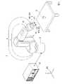
FIG. 1 is a diagram showing an example of the configuration of a
ロボット20は、アームAと、アームAを支持する基台Bを備える単腕ロボットである。単腕ロボットは、この一例におけるアームAのような1本のアーム(腕)を備えるロボットのことである。 The
アームAは、エンドエフェクターEと、マニピュレーターMと、力検出部FSを備える。なお、アームAは、エンドエフェクターEを備えない構成であってもよい。 Arm A includes an end effector E, a manipulator M, and a force detector FS. Note that the arm A may be configured without the end effector E.
エンドエフェクターEは、1以上の指部と、当該1以上の指部のそれぞれを支持する基部EBを備え、当該1以上の指部によって物体を挟んで持つことにより把持するエンドエフェクターである。また、エンドエフェクターEでは、エンドエフェクターEが備える1以上の指部が、基部EBに対して移動可能に設けられている。以下では、一例として、エンドエフェクターEが、図1に示したように、第1指部F1と第2指部F2との2つの指部を備える場合について説明する。なお、エンドエフェクターEは、把持部の一例である。 The end effector E is an end effector that includes one or more fingers and a base EB that supports each of the one or more fingers, and grips an object by sandwiching it with the one or more fingers. Further, in the end effector E, one or more finger portions of the end effector E are provided movably with respect to the base portion EB. As an example, the case where the end effector E has two fingers, a first finger F1 and a second finger F2, as shown in FIG. 1 will be described below. It should be noted that the end effector E is an example of a grip portion.
第1指部F1と第2指部F2は、基部EBが有する面のうち第1指部及び第2指部が設けられた面上において予め決められた1本の直線に沿って互いに対向するように基部EBに対して設けられている。また、第1指部F1と第2指部F2は、基部EBに対して当該直線に沿って移動可能に設けられている。すなわち、エンドエフェクターEにおいて、第1指部F1と第2指部F2は、互いに近づくように、又は、互いに遠のくように、1次元的に基部EBに対して移動可能である。これにより、エンドエフェクターEは、第1指部F1と第2指部F2とのそれぞれが互いに近づく方向に第1指部F1と第2指部F2とのいずれか一方又は両方を移動させて物体を挟むことができる。以下では、説明の便宜上、当該直線に沿った2つの方向のうち第1指部F1から第2指部F2に向かう方向を第1方向と称し、当該2つの方向のうち第2指部F2から第1指部F1に向かう方向を第2方向と称して説明する。なお、当該直線は、当該面上において予め決められた直線であれば、如何なる直線であってもよい。以下では、一例として、当該直線が、当該面に直交する方向に沿って当該面を見た場合においてエンドエフェクターEの重心を通る直線である場合について説明する。 The first finger F1 and the second finger F2 face each other along a predetermined straight line on the surface of the base EB on which the first finger and the second finger are provided. are provided with respect to the base EB. Also, the first finger F1 and the second finger F2 are provided so as to be movable along the straight line with respect to the base EB. That is, in the end effector E, the first finger portion F1 and the second finger portion F2 are one-dimensionally movable with respect to the base portion EB so as to approach each other or move away from each other. As a result, the end effector E moves one or both of the first finger F1 and the second finger F2 in a direction in which the first finger F1 and the second finger F2 approach each other, thereby moving the object. can be sandwiched. Hereinafter, for convenience of explanation, of the two directions along the straight line, the direction from the first finger F1 to the second finger F2 will be referred to as the first direction. The direction toward the first finger F1 will be referred to as the second direction in the description. Note that the straight line may be any straight line as long as it is a straight line that is predetermined on the surface. In the following, as an example, a case will be described in which the straight line passes through the center of gravity of the end effector E when the surface is viewed along a direction orthogonal to the surface.
なお、第1指部F1は、基部EBに対して2本以上の直線に沿って移動可能に設けられている構成であってもよい。当該2本以上の直線は、基部EBが有する面のうち第1指部及び第2指部が設けられた面上において予め決められた2本以上の直線のことである。ただし、この場合、エンドエフェクターEでは、第2指部F2は、基部EBに対して、当該2本以上の直線のうちのいずれか1本に沿って移動可能に設けられる。
また、第2指部F2は、基部EBに対して2本以上の直線に沿って移動可能に設けられている構成であってもよい。当該2本以上の直線は、基部EBが有する面のうち第1指部及び第2指部が設けられた面上において予め決められた2本以上の直線のことである。ただし、この場合、エンドエフェクターEでは、第1指部F1は、基部EBに対して、当該2本以上の直線のうちのいずれか1本に沿って移動可能に設けられる。Note that the first finger portion F1 may be configured to be movable along two or more straight lines with respect to the base portion EB. The two or more straight lines are predetermined two or more straight lines on the surface of the base EB on which the first finger portion and the second finger portion are provided. However, in this case, in the end effector E, the second finger F2 is provided movably along any one of the two or more straight lines with respect to the base EB.
Further, the second finger portion F2 may be configured to be movable along two or more straight lines with respect to the base portion EB. The two or more straight lines are predetermined two or more straight lines on the surface of the base EB on which the first finger portion and the second finger portion are provided. However, in this case, in the end effector E, the first finger F1 is provided movably along any one of the two or more straight lines with respect to the base EB.
また、エンドエフェクターEは、基部EBに対して第1指部F1を動かす第1駆動部MT1と、基部EBに対する第1指部F1の位置を検出する第1位置検出部EC1と、基部EBに対して第2指部F2を動かす第2駆動部MT2と、基部EBに対する第2指部F2の位置を検出する第2位置検出部EC2を備える。 Further, the end effector E includes a first driving section MT1 for moving the first finger F1 with respect to the base EB, a first position detection section EC1 for detecting the position of the first finger F1 with respect to the base EB, and a A second driving section MT2 for moving the second finger F2 and a second position detecting section EC2 for detecting the position of the second finger F2 with respect to the base EB are provided.
第1駆動部MT1及び第2駆動部MT2は、アクチュエーターであり、例えば、サーボモーターである。なお、第1駆動部MT1は、サーボモーターに代えて、基部EBに対して第1指部F1を動かすことが可能な他のアクチュエーターであってもよい。また、第2駆動部MT2は、サーボモーターに代えて、基部EBに対して第2指部F2を動かすことが可能な他のアクチュエーターであってもよい。 The first driving section MT1 and the second driving section MT2 are actuators, for example, servo motors. Note that the first driving portion MT1 may be another actuator capable of moving the first finger portion F1 with respect to the base portion EB instead of the servomotor. Further, the second driving part MT2 may be another actuator capable of moving the second finger part F2 with respect to the base part EB instead of the servomotor.
第1位置検出部EC1及び第2位置検出部EC2は、エンコーダーである。第1位置検出部EC1は、例えば、光学式エンコーダーであってもよく、磁気式エンコーダーであってもよく、光学式と磁気式とを組み合わせた形式のエンコーダーであってもよく、基部EBに対する第1指部F1の位置を検出可能な他の形式のエンコーダーであってもよい。第2位置検出部EC2は、例えば、光学式エンコーダーであってもよく、磁気式エンコーダーであってもよく、光学式と磁気式とを組み合わせた形式のエンコーダーであってもよく、基部EBに対する第2指部F2の位置を検出可能な他の形式のエンコーダーであってもよい。 The first position detector EC1 and the second position detector EC2 are encoders. The first position detection unit EC1 may be, for example, an optical encoder, a magnetic encoder, or an encoder combining optical and magnetic methods. Other types of encoders capable of detecting the position of one finger F1 may be used. The second position detection unit EC2 may be, for example, an optical encoder, a magnetic encoder, or an encoder combining optical and magnetic methods. Other types of encoders capable of detecting the position of the two fingers F2 may be used.
第1位置検出部EC1は、基部EBに対する第1指部F1の位置を検出し、検出した位置を示す情報を第1位置検出情報としてロボット制御装置30に出力する。 The first position detector EC1 detects the position of the first finger F1 with respect to the base EB, and outputs information indicating the detected position to the
第2位置検出部EC2は、基部EBに対する第2指部F2の位置を検出し、検出した位置を示す情報を第2位置検出情報としてロボット制御装置30に出力する。 The second position detector EC2 detects the position of the second finger F2 with respect to the base EB, and outputs information indicating the detected position to the
なお、第1駆動部MT1と第1位置検出部EC1とは、一体に構成されてもよく、それぞれ別体として構成されてもよい。図1に示した例では、第1駆動部MT1と第1位置検出部EC1とは、一体に構成されている。 The first driving section MT1 and the first position detecting section EC1 may be configured integrally or may be configured separately. In the example shown in FIG. 1, the first drive section MT1 and the first position detection section EC1 are configured integrally.
また、第2駆動部MT2と第2位置検出部EC2とは、一体に構成されてもよく、それぞれ別体として構成されてもよい。図1に示した例では、第2駆動部MT2と第2位置検出部EC2とは、一体に構成されている。 Further, the second driving section MT2 and the second position detecting section EC2 may be configured integrally, or may be configured separately. In the example shown in FIG. 1, the second drive section MT2 and the second position detection section EC2 are configured integrally.
マニピュレーターMは、6つの関節を備えた垂直多関節型のマニピュレーターである。また、マニピュレーターMが備える6つの関節はそれぞれ、図示しないアクチュエーターを備える。すなわち、マニピュレーターMを備えるアームAは、6軸垂直多関節型のアームである。アームAは、基台Bと、エンドエフェクターEと、マニピュレーターMと、マニピュレーターMが備える6つの関節それぞれのアクチュエーターとによる連携した動作によって6軸の自由度の動作を行う。なお、アームAは、5軸以下の自由度で動作する構成であってもよく、7軸以上の自由度で動作する構成であってもよい。 The manipulator M is a vertical articulated manipulator with six joints. Also, each of the six joints of the manipulator M has an actuator (not shown). That is, the arm A having the manipulator M is a 6-axis vertical articulated arm. The arm A performs motions with six degrees of freedom through coordinated motions by the base B, the end effector E, the manipulator M, and the actuators of the six joints of the manipulator M. The arm A may be configured to operate with five or less degrees of freedom, or may be configured to operate with seven or more degrees of freedom.
力検出部FSは、エンドエフェクターEとマニピュレーターMの間に設けられる。力検出部FSは、例えば、水晶を含む力検出素子を4つ備える。そして、力検出部FSは、4つの水晶のそれぞれに加わる剪断力に基づいて、ロボット20の図示しないハンドに作用した外力を検出する。これにより、ロボット20は、水晶を含まない力検出素子を4つ備えた力センサーと比べて、力検出部FSから出力される出力値が、温度等の環境因子の変化、経年劣化等に応じて変動してしまうことを抑制することができる。 A force detection unit FS is provided between the end effector E and the manipulator M. As shown in FIG. The force detection unit FS includes, for example, four force detection elements containing crystals. Then, the force detection unit FS detects an external force acting on the hand (not shown) of the
ここで、ロボット20のハンドは、エンドエフェクターE、又はエンドエフェクターEにより把持された物体のことである。すなわち、力検出部FSは、エンドエフェクターE、又はエンドエフェクターEにより把持された物体に作用した外力を検出する。当該外力には、当該ハンドを並進させる並進力が含まれる。当該並進力には、図1において図示しない力検出座標系FCにおけるX軸、Y軸、Z軸それぞれの方向に作用する3つの並進力が含まれている。ここで、力検出座標系FCは、力検出部FSに対応付けられた三次元直交座標系のことである。また、当該外力には、当該ハンドを回転させる回転モーメント(トルク)が含まれる。当該回転モーメントには、当該X軸、当該Y軸、当該Z軸それぞれの周りに作用する3つの回転モーメントが含まれている。すなわち、力検出部FSは、当該3つの並進力と当該3つの回転モーメントとのそれぞれを当該外力として検出する。力検出部FSは、検出した当該3つの並進力のそれぞれに応じた出力値と、検出した当該3つの回転モーメントのそれぞれに応じた出力値との6つの出力値のそれぞれを示す情報を外力検出情報としてロボット制御装置30に出力する。すなわち、当該6つの出力値のうちの一部又は全部は、力検出部から出力される出力値の一例である。 Here, the hand of the
外力検出情報は、ロボット制御装置30によるロボット20の力制御に用いられる。力制御は、力検出部FSから出力された出力値に基づく制御、すなわち、力検出部FSからロボット制御装置30に出力された外力検出情報に基づく制御のことであり、例えば、インピーダンス制御等のコンプライアントモーション制御のことである。 The external force detection information is used for force control of the
なお、力検出部FSは、水晶を含む力検出素子を3つ以下備える構成であってもよく、水晶を含む力検出素子を5つ以上備える構成であってもよい。また、力検出部FSは、水晶を含む4つの力検出素子のうちの一部又は全部に代えて、水晶を含まない力検出素子を備える構成であってもよい。また、力検出部FSは、水晶を含む4つの力検出素子のうちの一部又は全部に加えて、水晶を含まない力検出素子を備える構成であってもよい。 Note that the force detection unit FS may be configured to include three or less force detection elements including crystals, or may be configured to include five or more force detection elements including crystals. Further, the force detection unit FS may be configured to include force detection elements that do not contain crystals instead of some or all of the four force detection elements that contain crystals. Further, the force detection unit FS may be configured to include force detection elements that do not contain crystals in addition to some or all of the four force detection elements that contain crystals.
ここで、第1駆動部MT1と、第2駆動部MT2と、第1位置検出部EC1と、第2位置検出部EC2と、マニピュレーターMが備える6つのアクチュエーターのそれぞれと、力検出部FSとは、ケーブルによってロボット制御装置30と通信可能に接続されている。なお、ケーブルを介した有線通信は、例えば、イーサネット(登録商標)やUSB(Universal Serial Bus)等の規格によって行われる。また、第1駆動部MT1と、第2駆動部MT2と、第1位置検出部EC1と、第2位置検出部EC2と、力検出部FSとのうちの一部又は全部は、Wi-Fi(登録商標)等の通信規格により行われる無線通信によってロボット制御装置30と接続される構成であってもよい。また、マニピュレーターMが備える6つのアクチュエーターのうちの一部又は全部は、Wi-Fi(登録商標)等の通信規格により行われる無線通信によってロボット制御装置30と接続される構成であってもよい。 Here, the first drive unit MT1, the second drive unit MT2, the first position detection unit EC1, the second position detection unit EC2, each of the six actuators included in the manipulator M, and the force detection unit FS , are communicably connected to the
ロボット制御装置30は、ロボット20を制御する。ロボット制御装置30は、ロボット制御装置30が備えるメモリーに予め記憶された動作プログラムに基づいて、ロボット20に予め決められた作業を行わせる。なお、図1では、図を簡略化するため、当該メモリーを図示していない。 The
より具体的には、ロボット制御装置30は、ロボット20のアームAとともに動く仮想的な点である制御点Tを、アームAの予め決められた位置に設定する。制御点Tは、例えば、アームAについてのTCP(Tool Center Point)である。なお、制御点Tは、当該TCPに代えて、制御点Tとともに動く他の仮想的な点であってもよい。当該予め決められた位置は、例えば、エンドエフェクターEの重心の位置である。なお、当該予め決められた位置は、当該重心の位置に代えて、アームAに応じた他の位置であってもよい。 More specifically, the
制御点Tには、制御点Tとともに動く三次元直交座標系である図示しない制御点座標系が対応付けられている。制御点Tの位置は、制御点座標系の原点のロボット座標系RCにおける位置によって表される。また、制御点Tの姿勢は、制御点座標系における各座標軸のロボット座標系RCにおける方向によって表される。ここで、ロボット座標系RCは、ロボット20の基台Bに対応付けられた三次元直交座標系のことである。以下では、一例として、ロボット座標系RCにおけるZ軸の負方向が重力方向と一致している場合について説明する。なお、ロボット座標系RCにおけるZ軸の負方向は、重力方向と一致していない構成であってもよい。 The control point T is associated with a control point coordinate system (not shown), which is a three-dimensional orthogonal coordinate system that moves together with the control point T. FIG. The position of the control point T is represented by the position in the robot coordinate system RC of the origin of the control point coordinate system. Also, the attitude of the control point T is represented by the direction of each coordinate axis in the control point coordinate system in the robot coordinate system RC. Here, the robot coordinate system RC is a three-dimensional orthogonal coordinate system associated with the base B of the
ロボット制御装置30は、前述の動作プログラムに基づく位置制御によってアームAを動作させる。当該位置制御において、ロボット制御装置30は、制御点Tを動作プログラムにより指定された教示点と一致させる。教示点は、制御点Tを一致させる目標となる仮想的な点のことである。教示点には、教示点の位置を示す教示点位置情報と、教示点の姿勢を示す教示点姿勢情報とが対応付けられている。ここで、この一例では、ある教示点と制御点Tとの一致は、当該教示点の位置及び姿勢と制御点Tの位置及び姿勢との一致を意味する。すなわち、当該位置制御において、この一例におけるロボット制御装置30は、制御点Tの位置及び姿勢を動作プログラムにより指定された教示点の位置及び姿勢と一致させる。 The
また、ロボット制御装置30は、力検出部FSから外力検出情報を取得し、取得した外力検出情報と、動作プログラムとに基づく力制御によってアームAを動作させる。当該力制御において、ロボット制御装置30は、アームAを動作させ、当該外力検出情報が示す6つの出力値のうち動作プログラムにより指定された1つ以上の出力値が、動作プログラムにより指定された目標値となるように制御点Tの位置及び姿勢を変化させる。この際、ロボット制御装置30は、当該1つ以上の出力値が当該目標値と一致するように制御点Tの位置及び姿勢を変化させる場合における制御点Tの位置及び姿勢それぞれの変化分を、力制御に応じた運動方程式を解くことによって算出する。この一例における力制御は、前述した通り、インピーダンス制御である。この一例における当該運動方程式は、インピーダンス制御に応じた運動方程式である。なお、当該力制御に応じた運動方程式については、公知であるため、これ以上の詳細な説明を省略する。 Further, the
ロボット制御装置30は、このような位置制御と力制御との少なくとも一方によってアームAを動作させ、ロボット20に予め決められた作業を行わせる。 The
予め決められた作業は、例えば、図1に示した物体Oを把持し、把持した物体Oを予め決められた図示しない領域に載置する作業である。なお、予め決められた作業は、何らかの物体を把持する動作を伴う作業であれば如何なる作業であってもよい。 The predetermined work is, for example, the work of gripping the object O shown in FIG. 1 and placing the gripped object O in a predetermined area (not shown). Note that the predetermined work may be any work as long as it involves an action of gripping some kind of object.
物体Oは、例えば、製品に組み付けるプレート、ネジ、ボルト等の産業用の部品や部材である。図1に示した例では、物体Oは、断面が十字型の柱形状の物体(十字型断面柱)であり、当該断面がロボット座標系RCにおけるX軸と直交するように載置されている。なお、物体Oは、産業用の部品や部材に代えて、日用品や生体等の他の物体であってもよい。また、物体Oの形状は、断面が十字型の柱形状に代えて、他の形状であってもよい。 The object O is, for example, an industrial part or member such as a plate, screw, or bolt to be attached to the product. In the example shown in FIG. 1, the object O is a columnar object with a cross-shaped cross section (cross-shaped cross-section column), and is placed so that the cross section is orthogonal to the X-axis in the robot coordinate system RC. . Note that the object O may be other objects such as daily necessities or a living body instead of industrial parts and members. Further, the shape of the object O may be another shape instead of the columnar shape having a cross-shaped cross section.
ここで、以下では、一例として、物体Oが剛体として近似可能な物体である場合について説明する。物体Oが剛体として近似可能な物体であることは、この一例において、エンドエフェクターEによって物体Oが把持された場合における物体Oの変形が、肉眼で検出不可能な程度の変形であることを意味する。なお、物体Oが剛体として近似可能な物体であることは、これに代えて、エンドエフェクターEによって物体Oが把持された場合における物体Oの変形が、定規、ノギス、マイクロメーターのうちのいずれかで検出不可能な程度の変形であることを意味してもよい。このような意味で、以下では、一例として、物体Oが、エンドエフェクターEによって把持されても変形しない場合について説明する。この場合、例えば、物体Oの材質は、鉄である。なお、物体Oの材質は、鉄に代えて、エンドエフェクターEによって把持されても変形しない他の材質であってもよい。 Here, below, as an example, a case where the object O is an object that can be approximated as a rigid body will be described. That the object O is an object that can be approximated as a rigid body means that, in this example, the deformation of the object O when it is gripped by the end effector E is a deformation that cannot be detected with the naked eye. do. It should be noted that the fact that the object O is an object that can be approximated as a rigid body means that the deformation of the object O when it is gripped by the end effector E is determined by any of a ruler, a vernier caliper, and a micrometer. It may mean that the deformation is undetectable by . In this sense, a case where the object O is not deformed even if it is gripped by the end effector E will be described below as an example. In this case, for example, the material of the object O is iron. It should be noted that the material of the object O may be other materials that do not deform even when gripped by the end effector E instead of iron.
<ロボット制御装置のハードウェア構成>
以下、図2を参照し、ロボット制御装置30のハードウェア構成について説明する。図2は、ロボット制御装置30のハードウェア構成の一例を示す図である。<Hardware configuration of robot controller>
The hardware configuration of the
ロボット制御装置30は、例えば、プロセッサー31と、メモリー32と、通信部34を備える。これらの構成要素は、バスを介して相互に通信可能に接続されている。また、ロボット制御装置30は、通信部34を介してロボット20と通信を行う。 The
プロセッサー31は、例えば、CPU(Central Processing Unit)である。なお、プロセッサー31は、CPUに代えて、FPGA(Field-Programmable Gate Array)等の他のプロセッサーであってもよい。プロセッサー31は、メモリー32に格納された各種のプログラムを実行する。
メモリー32は、前述のメモリーの一例である。メモリー32は、例えば、HDD(Hard Disk Drive)やSSD(Solid State Drive)、EEPROM(Electrically Erasable Programmable Read-Only Memory)、ROM(Read-Only Memory)、RAM(Random Access Memory)等を含む。なお、メモリー32は、ロボット制御装置30に内蔵されるものに代えて、USB等のデジタル入出力ポート等によってロボット制御装置30に接続された外付け型の記憶装置であってもよい。メモリー32は、ロボット制御装置30が処理する各種の情報、動作プログラム等を格納する。
通信部34は、例えば、USB等のデジタル入出力ポートやイーサネット(登録商標)ポート等を含んで構成される。The
The
なお、ロボット制御装置30は、キーボード、マウス、タッチパッド等の入力装置と、ディスプレイを有する表示装置とのいずれか一方又は両方を備える構成であってもよい。 Note that the
<ロボット制御装置の機能構成>
以下、図3を参照し、ロボット制御装置30の機能構成について説明する。図3は、ロボット制御装置30の機能構成の一例を示す図である。<Functional configuration of robot controller>
The functional configuration of the
ロボット制御装置30は、メモリー32と、通信部34と、制御部36を備える。 The
制御部36は、ロボット制御装置30の全体を制御する。制御部36は、取得部361と、判定部363と、ロボット制御部365を備える。制御部36が備えるこれらの機能部は、例えば、プロセッサー31が、メモリー32に記憶された各種の指令を実行することにより実現される。また、当該機能部のうちの一部又は全部は、LSI(Large Scale Integration)、ASIC(Application Specific Integrated Circuit)等のハードウェア機能部であってもよい。 The
取得部361は、第1位置検出部EC1から出力される第1位置検出情報を第1位置検出部EC1から取得する。また、取得部361は、第2位置検出部EC2から出力される第2位置検出情報を第2位置検出部EC2から取得する。また、取得部361は、力検出部FSから出力される外力検出情報を力検出部FSから取得する。 The
判定部363は、ロボット制御装置30が行う各種の判定を行う。判定部363が行う判定の具体例については、後述する。 The
ロボット制御部365は、メモリー32に予め記憶された動作プログラムをメモリー32から読み出す。ロボット制御部365は、読み出した動作プログラムに基づいてロボット20を制御する。 The
なお、制御部36において、取得部361と、判定部363と、ロボット制御部365とのうちの一部又は全部は、1つの機能部として構成されてもよい。 In the
<ロボット制御装置がロボットに予め決められた作業を行わせる処理>
以下、図4を参照し、ロボット制御装置30がロボット20に予め決められた作業を行わせる処理について説明する。図4は、ロボット制御装置30がロボット20に予め決められた作業を行わせる処理の流れの一例を示す図である。以下では、一例として、図4に示したステップS110の処理が行われるよりも前のタイミングにおいて、メモリー32に予め決められた動作プログラムをロボット制御部365がメモリー32から読み出している場合について説明する。また、以下では、一例として、当該タイミングにおいて、ロボット20の動作を開始させる操作をロボット制御装置30が受け付けている場合について説明する。<Processing by the robot control device causing the robot to perform a predetermined task>
Hereinafter, with reference to FIG. 4, the process of causing the
判定部363は、メモリー32に予め記憶された第1情報をメモリー32から読み出す(ステップS110)。第1情報は、この一例において、後述するステップS180において行われる第1判定処理において用いられる所定の値を示す情報のことである。なお、ステップS110の処理は、ステップS180の処理が行われるよりも前のタイミングであれば、如何なるタイミングにおいて行われてもよい。 The
次に、ロボット制御部365は、メモリー32から予め読み出した動作プログラムに基づく位置制御によってアームAを動作させ、予め決められた作業を開始させる直前に制御点Tを待機させる教示点と制御点Tとを一致させる(ステップS120)。以下では、一例として、当該教示点の位置が、当該教示点に制御点Tが一致した場合において、エンドエフェクターEと他の物体とが接触しない位置であり、且つ、当該作業を行う対象となる物体Oが第1指部F1と第2指部F2との間に位置する位置である場合について説明する。ここで、第1指部F1と第2指部F2との間は、第1指部F1と第2指部F2とを近づけた場合において第1指部F1と第2指部F2とによって挟まれて把持される領域のことを示す。また、以下では、一例として、当該教示点の姿勢が、当該教示点に制御点Tが一致した場合において、物体OとエンドエフェクターEとが接触しない姿勢であり、且つ、エンドエフェクターEに応じた軸が重力方向と並行になる姿勢である場合について説明する。エンドエフェクターEに応じた軸は、例えば、エンドエフェクターEとともに動く軸であり、且つ、マニピュレーターMが備える6つの関節のうち最もエンドエフェクターE側の関節の回動軸と一致する軸である。なお、当該教示点の位置は、当該教示点に制御点Tが一致した場合において、物体OとエンドエフェクターEとが接触しない位置であれば他の位置であってもよい。また、当該教示点の姿勢は、当該教示点に制御点Tが一致した場合において、物体OとエンドエフェクターEとが接触しない姿勢であれば他の姿勢であってもよい。また、エンドエフェクターEに応じた軸は、エンドエフェクターEとともに動く他の軸であってもよい。 Next, the
次に、ロボット制御部365は、メモリー32から予め読み出した動作プログラムに基づく力制御によって、第1動作をロボット20に開始させる(ステップS130)。ここで、図5を参照し、第1動作について説明する。 Next, the
図5は、予め決められた作業を開始させる直前にロボット制御装置30が制御点Tを待機させる教示点と制御点Tとが一致している様子の一例を示す図である。以下では、一例として、図5に示したように、第1指部F1と第2指部F2とのそれぞれが移動可能な方向が、ロボット座標系RCにおけるY軸に沿った方向と一致している場合について説明する。また、以下では、一例として、前述の力検出座標系FCにおけるX軸の正方向とロボット座標系RCにおけるX軸の正方向とが一致し、力検出座標系FCにおけるY軸の正方向とロボット座標系RCにおけるY軸の負方向とが一致し、力検出座標系FCにおけるZ軸の正方向とロボット座標系RCにおけるZ軸の負方向とが一致している場合について説明する。また、図5に示した軸AXOは、物体Oに応じた軸である。物体Oに応じた軸は、例えば、物体Oの重心を通る軸のうち重力方向と並行な軸のことである。なお、物体Oに応じた軸は、物体Oの重心を通る軸のうち重力方向と並行な軸に代えて、物体Oに応じた他の軸であってもよい。図5に示したように、当該教示点と制御点Tとが一致している場合、軸AXEは、重力方向と並行になっている。また、図5に示したように、当該場合、物体Oは、第1指部F1と第2指部F2との間に位置している。 FIG. 5 is a diagram showing an example of how the control point T coincides with the teaching point at which the
ここで、ステップS130においてロボット制御部365は、力制御によって第1指部F1を物体Oに接触させる動作を第1動作としてロボット20に開始させる。この一例では、ステップS130においてロボット制御部365は、動作プログラムに基づいて、力検出部FSから出力された外力検出情報が示す6つの出力値のうち力検出座標系FCにおけるY軸の正方向に作用する並進力に応じた出力値に対して、所定の第1閾値を力制御における目標値として設定する。これにより、ロボット制御部365は、当該出力値が第1閾値以上となるまで制御点Tを当該Y軸の負方向(すなわち、ロボット座標系RCにおけるY軸の正方向)に向かって移動させる動作を第1動作としてロボット20に行わせる。図5では、力検出座標系FCにおけるY軸の負方向は、矢印A1が示す方向によって示されている。 Here, in step S130, the
このような力制御によって、ロボット制御部365は、エンドエフェクターEの全体を矢印A1が示す方向に移動させる。ここで、本実施形態では、エンドエフェクターEの全体を移動させることは、基部EBと第1指部F1及び第2指部F2それぞれとの相対的な位置関係を変えずにエンドエフェクターEを移動させることを意味する。すなわち、この一例では、ステップS120の処理が行われた後、ロボット制御部365は、ロボット座標系RCにおけるY軸の正方向に当該位置関係を変えずにエンドエフェクターEを力制御によって移動させ、第1指部F1を物体Oに接触させる動作を第1動作としてロボット20に開始させる。換言すると、ステップS130では、ロボット制御部365は、第1指部F1を物体Oに接触させ、力検出部FSから出力される出力値が所定の第1閾値以上となるまで第1指部F1を物体Oに付勢させる動作を第1動作としてロボット20に行わせ始める。なお、第1動作において、ロボット制御部365は、基部EBを移動させずに、基部EBに対して第1指部F1を第1方向(この一例において、矢印A1が示す方向)に向かって移動させて第1指部F1を物体Oに接触させる構成であってもよい。また、第1動作において、ロボット制御部365は、基部EBを矢印A1が示す方向を移動させるとともに、基部EBに対して第1指部F1を第1方向(この一例において、矢印A1が示す方向)に向かって移動させて第1指部F1を物体Oに接触させる構成であってもよい。 Through such force control, the
ステップS130においてロボット制御部365が力制御によって第1動作をロボット20に開始させた後、判定部363は、取得部361が力検出部FSから取得した外力検出情報が示す6つの出力値のうち、力検出座標系FCにおけるY軸の正方向に作用する並進力に応じた出力値が第1閾値以上であるか否かを判定する(ステップS140)。当該出力値が第1閾値未満であると判定部363が判定した場合(ステップS140-NO)、ロボット制御部365は、ステップS130において開始させた第1動作をロボット20に継続させる。一方、当該出力値が第1閾値以上であると判定部363が判定した場合(ステップS140-YES)、ロボット制御部365は、ロボット20の動作を停止させ、ロボット20の第1動作を終了させる。そして、ロボット制御部365は、動作プログラムに基づく力制御によって、第2動作をロボット20に開始させる(ステップS150)。ここで、図6を参照し、第2動作について説明する。 After the
図6は、図5に示したエンドエフェクターEと物体Oとの位置関係のうちロボット20の第1動作が終了した直後における位置関係の一例を示す図である。ステップS150においてロボット制御部365は、力検出部FSから出力される出力値のうち力検出座標系FCにおけるY軸の正方向に作用する並進力に応じた出力値を保持しながら物体O(又は第1指部F1)に対する第2指部F2の位置を変化させて物体Oを第1指部F1と第2指部F2とによって把持させる動作を第2動作としてロボット20に開始させる。例えば、ロボット制御部365は、物体O及び第1指部F1の両方の位置を変化させることなく、基台Bと第2指部F2とのうちいずれか一方又は両方を動かすことによって物体Oに対する第2指部F2の位置を物体Oに近づけ、物体Oを第1指部F1と第2指部F2とによって把持させる動作を第2動作としてロボット20に開始させる。また、例えば、ロボット制御部365は、物体Oに対する第1指部F1の位置を変化させることなく第1指部F1を第1方向に移動させることによって物体Oを移動させるとともに、基台Bと第2指部F2とのうちいずれか一方又は両方を動かすことによって物体Oに対する第2指部F2の位置を物体Oに近づけ、物体Oを第1指部F1と第2指部F2とによって把持させる動作を第2動作としてロボット20に開始させる。以下では、一例として、ロボット制御部365が、物体O及び第1指部F1の両方の位置を変化させることなく、基台Bと第2指部F2との両方を動かすことによって物体Oに対する第2指部F2の位置を物体Oに近づけ、物体Oを第1指部F1と第2指部F2とによって把持させる動作を第2動作としてロボット20に開始させる場合について説明する。換言すると、ステップS150では、ロボット制御部365は、力検出部FSから出力される出力値が第1閾値以上である状態を維持し、第1指部F1とアームAとを移動させ、物体Oに第1指部F1と第2指部F2とを接触させる動作を第2動作としてロボット20に行わせ始める。 FIG. 6 is a diagram showing an example of the positional relationship between the end effector E and the object O shown in FIG. 5 immediately after the first motion of the
また、第2動作において、ロボット制御部365は、更に、軸AXEが第1指部F1と第2指部F2との中間に位置するように基部EBを第1指部F1及び第2指部F2のそれぞれに対して移動させる動作をロボット20に行わせる。これにより、ロボット制御装置30は、エンドエフェクターEによって物体Oと把持させた場合において、エンドエフェクターEに応じた軸と、物体Oに応じた軸とを一致させることができる。より具体的には、これにより、ロボット制御装置30は、当該場合において、力検出部FSから出力される出力値のうち3つの回転モーメントのそれぞれに応じた出力値をすべてゼロにすることができる。その結果、ロボット制御装置30は、エンドエフェクターEによる物体Oの把持が不安定になってしまうことを抑制することができる。
エンドエフェクターEに応じた軸と、物体Oに応じた軸とが一致した状態とは、物体OがエンドエフェクターEに対して所定の位置であり、且つ、物体OがエンドエフェクターEに対して所定の姿勢である状態である。所定の位置とは、例えば、当該エンドエフェクターEに応じた軸と、当該物体Oに応じた軸と、が重なる位置である。また、所定の姿勢とは、例えば、当該エンドエフェクターEに応じた軸と、当該物体Oに応じた軸と、が平行となる姿勢である。In addition, in the second operation, the
The state in which the axis corresponding to the end effector E and the axis corresponding to the object O are aligned is that the object O is at a predetermined position with respect to the end effector E, and the object O is at a predetermined position with respect to the end effector E. It is a state that is in the posture of The predetermined position is, for example, a position where an axis corresponding to the end effector E and an axis corresponding to the object O overlap. Further, the predetermined posture is, for example, a posture in which the axis corresponding to the end effector E and the axis corresponding to the object O are parallel.
図6では、第2動作において基部EBに対して第2指部F2が移動する第2方向が、矢印A3によって示されている。また、図6では、第2動作において第1指部F1及び第2指部F2に対して基部EBが移動する方向が、矢印A4によって示されている。そして、図6に示した例では、第1指部F1及び物体Oの両方が移動していない。 In FIG. 6, the second direction in which the second finger F2 moves relative to the base EB in the second motion is indicated by an arrow A3. Also, in FIG. 6, the direction in which the base EB moves with respect to the first finger F1 and the second finger F2 in the second motion is indicated by an arrow A4. In the example shown in FIG. 6, neither the first finger F1 nor the object O are moving.
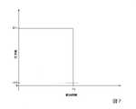
ここで、第2動作を行うことによって第2指部F2が物体Oに接触し始めると、力検出部FSから出力される出力値のうち力検出座標系FCにおけるY軸の正方向に作用する並進力に応じた出力値は、第1閾値よりも小さくなる。具体的には、当該出力値は、第2動作を行うことによって第2指部F2が物体Oに接触し始めると、図7に示したように低下する。図7は、力検出部FSから出力される出力値のうち力検出座標系FCにおけるY軸の正方向に作用する並進力に応じた出力値の第2動作における変化の一例を示す図である。図7に示したグラフの横軸は、第2動作における経過時間を示す。当該グラフの縦軸は、当該出力値の大きさを示す。図7に示した値EF1は、第1閾値を示す。図7に示したタイミングTSは、第2動作において第2指部F2が物体Oに接触したタイミングを示す。 Here, when the second finger F2 starts to come into contact with the object O by performing the second action, the output value output from the force detection unit FS acts in the positive direction of the Y axis in the force detection coordinate system FC. The output value according to the translational force becomes smaller than the first threshold. Specifically, the output value decreases as shown in FIG. 7 when the second finger F2 starts contacting the object O by performing the second action. FIG. 7 is a diagram showing an example of a change in the second operation of the output values output from the force detection unit FS according to the translational force acting in the positive direction of the Y-axis in the force detection coordinate system FC. . The horizontal axis of the graph shown in FIG. 7 indicates the elapsed time in the second action. The vertical axis of the graph indicates the magnitude of the output value. A value EF1 shown in FIG. 7 indicates the first threshold. Timing TS shown in FIG. 7 indicates the timing at which the second finger F2 contacts the object O in the second action.
第2動作において第2指部F2が物体Oに接触し始めると、物体Oには、第1指部F1と第2指部F2とのそれぞれから互いに反対向きに互いにほぼ同じ大きさの力が加えられ始める。このため、図7に示したように、力検出部FSから出力される出力値のうち力検出座標系FCにおけるY軸の正方向に作用する並進力に応じた出力値は、タイミングTSからほぼ時間が経過することなく値EF1からゼロ(又はほぼゼロ)へと低下する。図7に示した例では、当該出力値は、タイミングTSからほぼ時間が経過することなく値EF1からゼロへと低下している。これは、第1指部F1から物体Oに加えられた力と、第2指部F2から物体Oに加えられた力との合力がゼロになった結果である。当該合力がゼロになることは、換言すると、エンドエフェクターEによって物体Oが把持されたことを示す。そこで、ロボット制御装置30は、後述するステップS160において当該出力値が所定の第2閾値未満となった場合、エンドエフェクターEにより物体Oが把持されたと判定し、ロボット20の動作を停止させ、第2動作を終了させる。第2閾値は、ゼロ以上第1閾値以下の値であれば如何なる値であってもよい。ここで、前述した通り、力検出部FSから出力される出力値のうち力検出座標系FCにおけるY軸の正方向に作用する並進力に応じた出力値は、タイミングTSからほぼ時間が経過することなく値EF1からゼロへと低下する。このため、第2閾値は、第1閾値と同じ値であってもよい。この場合、ロボット制御装置30は、当該出力値が第1閾値未満となった場合、エンドエフェクターEにより物体Oが把持されたと判定する。また、第2閾値は、図7に示したように、ゼロ以上第1閾値未満の値であってもよい。図7に示した値EF2は、第2閾値の一例を示す。なお、ロボット制御装置30は、ステップS160において当該出力値が予め決められた第3閾値以下となった場合、エンドエフェクターEにより物体Oが把持されたと判定し、ロボット20の動作を停止させ、第2動作を終了させる構成であってもよい。第3閾値は、第2閾値よりも小さい値であり、例えば、ゼロである。 When the second finger F2 starts contacting the object O in the second motion, the forces of the first finger F1 and the second finger F2 are applied to the object O in opposite directions with substantially the same magnitude. begin to be added. Therefore, as shown in FIG. 7, among the output values output from the force detection unit FS, the output value corresponding to the translational force acting in the positive direction of the Y-axis in the force detection coordinate system FC is approximately It drops from the value EF1 to zero (or nearly zero) in no time. In the example shown in FIG. 7, the output value decreases from the value EF1 to zero in almost no time after the timing TS. This is the result that the resultant force of the force applied to the object O by the first finger F1 and the force applied to the object O by the second finger F2 becomes zero. When the resultant force becomes zero, in other words, it indicates that the end effector E has gripped the object O. Therefore, when the output value becomes less than a predetermined second threshold value in step S160, which will be described later, the
なお、本実施形態において、力検出部FSから出力される出力値のうち力検出座標系FCにおけるY軸の正方向に作用する並進力に応じた出力値の変化は、当該出力値の誤差による変動幅を超えた変化のことを意味する。すなわち、本実施形態では、当該出力値の誤差による低下は、当該出力値の低下として扱わない。 In this embodiment, among the output values output from the force detection unit FS, the change in the output value corresponding to the translational force acting in the positive direction of the Y-axis in the force detection coordinate system FC is due to the error in the output value. It means a change that exceeds the fluctuation range. That is, in the present embodiment, a decrease due to an error in the output value is not treated as a decrease in the output value.
ステップS150においてロボット制御部365が力制御によって第2動作をロボット20に開始させた後、判定部363は、取得部361が力検出部FSから取得した外力検出情報が示す6つの出力値のうち、力検出座標系FCにおけるY軸の正方向に作用する並進力に応じた出力値が第2閾値未満であるか否かを判定する(ステップS160)。当該出力値が第2閾値以上であると判定部363が判定した場合(ステップS160-NO)、ロボット制御部365は、ステップS150において開始させた第2動作をロボット20に継続させる。一方、当該出力値が第2閾値未満であると判定部363が判定した場合(ステップS140-YES)、ロボット制御部365は、エンドエフェクターEにより物体Oが把持されたと判定し、ロボット20の動作を停止させ、ロボット20の第2動作を終了させる。ただし、ロボット制御部365は、当該場合において、軸AXEが第1指部F1と第2指部F2との中間に位置するように基部EBを第1指部F1及び第2指部F2のそれぞれに対して移動させる動作が完了していない場合、当該動作を完了させてから、エンドエフェクターEにより物体Oが把持されたと判定し、ロボット20の動作を停止させ、ロボット20の第2動作を終了させる。 After the
ここで、図8は、図5に示したエンドエフェクターEと物体Oとの位置関係のうちロボット20の第2動作が終了した直後における位置関係の一例を示す図である。図8に示したように、第2動作が終了した場合において、軸AXEと軸AXOとは、一致している。また、この一例では、第2動作において第1指部F1が第1方向に移動しないため、図8に示した物体Oの位置は、図6に示した物体Oの位置と一致している。 Here, FIG. 8 is a diagram showing an example of the positional relationship between the end effector E and the object O shown in FIG. 5 immediately after the second motion of the
ステップS140においてロボット制御部365がロボット20の第2動作を終了させた場合、取得部361は、第1位置検出部EC1から第1位置検出情報を取得するとともに、第2位置検出部EC2から第2位置検出情報を取得する(ステップS170)。図4に示したフローチャートでは、このようなステップS170における取得部361の処理を、位置検出情報取得と示している。 When the
次に、判定部363は、ステップS170において取得部361が取得した第1位置検出情報及び第2位置検出情報に基づいて、第1判定処理を行う(ステップS180)。 Next, the
ここで、ステップS180の処理について説明する。第1判定処理は、ロボット制御装置30が行う判定のうち、所定の状態で物体Oが第1指部F1と第2指部F2とによって把持されているか否かの判定を行う処理である。この一例において、所定の状態は、エンドエフェクターEに対する物体Oの位置及び姿勢が所定の位置及び姿勢と一致している状態のことである。なお、所定の状態は、エンドエフェクターEに対する物体Oの位置が所定の位置と一致している状態のことであってもよく、エンドエフェクターEに対する物体Oの姿勢が所定の姿勢と一致している状態のことであってもよく、エンドエフェクターEと物体Oとに応じた他の状態であってもよい。 Here, the processing of step S180 will be described. The first determination process is a process of determining whether or not the object O is being gripped by the first finger F1 and the second finger F2 in a predetermined state among the determinations made by the
所定の状態で物体Oが第1指部F1と第2指部F2とによって把持された場合、物体Oに予め決められた2つの部位のうちの一方が第1指部F1によって押圧されるとともに、当該2つの部位のうちの他方が第2指部F2によって押圧される。以下では、説明の便宜上、当該2つの部位のうち所定の状態において第1指部F1によって押圧される部位のことを第1把持部位と称し、当該2つの部位のうち所定の状態において第2指部F2によって押圧される部位のことを第2把持部位と称して説明する。 When the object O is gripped by the first finger F1 and the second finger F2 in a predetermined state, one of two predetermined parts of the object O is pressed by the first finger F1. , the other of the two parts is pressed by the second finger F2. Hereinafter, for convenience of explanation, the portion of the two portions that is pressed by the first finger portion F1 in the predetermined state will be referred to as the first grip portion, and the portion that is pressed by the first finger portion F1 in the predetermined state of the two portions will be referred to as the first gripping portion. The portion pressed by the portion F2 will be referred to as a second gripping portion and will be described.
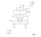
また、所定の状態で物体Oが第1指部F1と第2指部F2とによって把持された場合、第1指部F1と第2指部F2との間の長さは、所定の状態に応じた長さと一致する。所定の状態に応じた長さは、すなわち、所定の状態で物体Oが第1指部F1と第2指部F2とによって把持された場合における第1指部F1と第2指部F2との間の長さのことである。換言すると、所定の状態に応じた長さは、前述の第1把持部位と第2把持部位との間の長さのことである。ここで、図9は、図5に示した物体Oがロボット20の第2動作によって所定の状態で第1指部F1と第2指部F2とによって把持されている様子の一例を示す図である。図9に示した面X1は、物体Oが有する面のうち第1指部F1が接触している面である。また、図9に示した面X2は、物体Oが有する面のうち第2指部F2が接触している面である。 Further, when the object O is gripped by the first finger F1 and the second finger F2 in a predetermined state, the length between the first finger F1 and the second finger F2 is Match the length accordingly. The length corresponding to the predetermined state is the distance between the first finger F1 and the second finger F2 when the object O is gripped by the first finger F1 and the second finger F2 in the predetermined state. It is the length in between. In other words, the length corresponding to the predetermined state is the length between the first gripping portion and the second gripping portion. Here, FIG. 9 is a diagram showing an example of how the object O shown in FIG. be. A surface X1 shown in FIG. 9 is a surface of the object O that is in contact with the first finger F1. A surface X2 shown in FIG. 9 is a surface of the object O that is in contact with the second finger F2.
ここで、所定の状態と異なる状態で物体Oが第1指部F1と第2指部F2とによって把持された場合、第1指部F1と第2指部F2との間の長さは、所定の状態に応じた長さと一致しない可能性が高い。 Here, when the object O is gripped by the first finger F1 and the second finger F2 in a state different from the predetermined state, the length between the first finger F1 and the second finger F2 is It is highly probable that it will not match the length depending on the given state.
例えば、図10は、図5に示した物体Oをロボット20が第2動作によって把持できなかった様子の一例を示す図である。物体Oをロボット20が第2動作によって把持できなかった場合、力検出座標系FCにおけるY軸の正方向に作用する並進力に応じた出力値は、第1指部F1と第2指部F2とが接触して互いに押圧し合うことによって第2閾値未満となる。このため、ロボット20の第2動作が終了した直後における第1指部F1と第2指部F2とは、図10に示したように互いに接触している。第1指部F1と第2指部F2とが接触している場合、第1指部F1と第2指部F2との間の長さはゼロである。すなわち、物体Oをロボット20が第2動作によって把持できなかった場合、第1指部F1と第2指部F2との間の長さは、所定の状態に応じた長さと一致しない。ここで、図10に示した長さD2は、当該場合における第1指部F1と第2指部F2との間の長さの一例を示す。 For example, FIG. 10 is a diagram showing an example of a state in which the
また、例えば、図11は、図5に示した物体Oがロボット20の第2動作によって所定の状態と異なる状態で第1指部F1と第2指部F2とによって把持されている様子の一例を示す図である。図11に示した状態は、エンドエフェクターEに対する物体Oの姿勢が所定の姿勢と一致しており、エンドエフェクターEに対する物体Oの位置が所定の位置と一致していない状態の一例である。以下では、説明の便宜上、当該状態のことを第1誤把持状態と称して説明する。第1誤把持状態では、ロボット20の第2動作が終了した直後において、第1指部F1と第2指部F2との間の長さが、所定の状態に応じた長さと異なる場合がある。ここで、図11に示した長さD3は、当該場合における第1指部F1と第2指部F2との間の長さの一例を示す。図11に示した例では、第1誤把持状態における第1指部F1と第2指部F2との間の長さは、所定の状態に応じた長さよりも短くなっている。すなわち、長さD3は、長さD1よりも短い。図示しない他の例では、第1誤把持状態における第1指部F1と第2指部F2との間の長さは、所定の状態に応じた長さよりも長くなることもある。第1誤把持状態において第1指部F1と第2指部F2との間の長さが所定の状態に応じた長さと異なってしまうことは、物体Oの幅が重力方向に沿って一定ではない場合に起こり得る。すなわち、物体Oの形状が複雑になるほど、第1誤把持状態において第1指部F1と第2指部F2との間の長さが所定の状態に応じた長さと異なってしまう可能性が高くなる。 Also, for example, FIG. 11 shows an example of a state in which the object O shown in FIG. It is a figure which shows. The state shown in FIG. 11 is an example of a state in which the posture of the object O with respect to the end effector E matches the predetermined posture, and the position of the object O with respect to the end effector E does not match the predetermined position. In the following, for convenience of explanation, this state will be referred to as a first erroneous gripping state. In the first erroneous gripping state, the length between the first finger F1 and the second finger F2 may differ from the length corresponding to the predetermined state immediately after the second motion of the
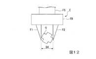
また、例えば、図12は、図5に示した物体Oがロボット20の第2動作によって所定の状態と異なる状態で第1指部F1と第2指部F2とによって把持されている様子の他の例を示す図である。図12に示した状態は、エンドエフェクターEに対する物体Oの位置が所定の位置と一致しており、エンドエフェクターEに対する物体Oの姿勢が所定の姿勢と一致していない状態の一例である。以下では、説明の便宜上、当該状態のことを第2誤把持状態と称して説明する。第2誤把持状態では、ロボット20の第2動作が終了した直後において、第1指部F1と第2指部F2との間の長さが、所定の状態に応じた長さと異なる場合がある。ここで、図12に示した長さD4は、当該場合における第1指部F1と第2指部F2との間の長さの一例を示す。図12に示した例では、第2誤把持状態における第1指部F1と第2指部F2との間の長さは、所定の状態に応じた長さよりも長くなっている。すなわち、長さD4は、長さD1よりも長い。図示しない他の例では、第2誤把持状態における第1指部F1と第2指部F2との間の長さは、所定の状態に応じた長さよりも短くなることもある。第2誤把持状態において第1指部F1と第2指部F2との間の長さが所定の状態に応じた長さと異なってしまうことは、物体Oの形状が球体形状ではない場合に起こり得る。すなわち、物体Oの形状が複雑になるほど、第2誤把持状態において第1指部F1と第2指部F2との間の長さが所定の状態に応じた長さと異なってしまう可能性が高くなる。 Also, for example, FIG. 12 shows a state in which the object O shown in FIG. It is a figure which shows the example of. The state shown in FIG. 12 is an example of a state in which the position of the object O with respect to the end effector E matches the predetermined position, and the posture of the object O with respect to the end effector E does not match the predetermined posture. In the following, for convenience of explanation, this state will be referred to as a second erroneous gripping state. In the second erroneous gripping state, the length between the first finger F1 and the second finger F2 may differ from the length according to the predetermined state immediately after the second motion of the
このように、所定の状態と異なる状態で物体Oが第1指部F1と第2指部F2とによって把持された場合、第1指部F1と第2指部F2との間の長さは、所定の状態に応じた長さと一致しない可能性が高い。 Thus, when the object O is gripped by the first finger F1 and the second finger F2 in a state different from the predetermined state, the length between the first finger F1 and the second finger F2 is , is likely not to match the length depending on the given state.
そこで、判定部363は、第1判定処理において、第1指部F1と第2指部F2との間の長さが、所定の状態に応じた長さと一致しているか否かを判定することにより、所定の状態で物体Oが第1指部F1と第2指部F2とによって把持されているか否かを判定する。すなわち、判定部363は、第1指部F1と第2指部F2との間の長さが、所定の状態に応じた長さと一致していないと判定した場合、所定の状態と異なる状態で物体Oが第1指部F1と第2指部F2とによって把持されていると判定する。一方、判定部363は、第1指部F1と第2指部F2との間の長さが、所定の状態に応じた長さと一致していると判定した場合、所定の状態で物体Oが第1指部F1と第2指部F2とによって把持されていると判定する。 Therefore, in the first determination process, the
より具体的には、判定部363は、第1判定処理において、ステップS170において取得部361が取得した第1位置検出情報及び第2位置検出情報に基づいて、第1指部F1に対する第2指部F2の位置を、第1指部F1と第2指部F2との間の長さとして検出(又は算出)する。当該長さは、第1位置検出部から出力される出力値に応じた値の一例であり、第1位置検出部から出力される出力値と第2位置検出部から出力される出力値とに応じた値の一例でもある。判定部363は、検出した長さと、メモリー32から予め読み出した第1情報が示す所定の値とが一致しているか否かを判定する。所定の値は、この一例において、所定の状態に応じた長さを示す値である。 More specifically, in the first determination process, the
そして、判定部363は、検出した長さと所定の値とが一致していないと判定した場合、所定の状態と異なる状態で物体Oが第1指部F1と第2指部F2とによって把持されていると判定する。一方、判定部363は、検出した長さと所定の値とが一致していると判定した場合、所定の状態で物体Oが第1指部F1と第2指部F2とによって把持されていると判定する。 If the determining
ここで、判定部363は、例えば、検出した長さを中心値とした誤差範囲に所定の値が含まれている場合、当該長さと所定の値とが一致していると判定する。一方、判定部363は、当該誤差範囲に所定の値が含まれている場合、当該長さと所定の値とが一致していると判定する。当該誤差範囲は、例えば、当該長さを中心値とした90%信頼区間の範囲であってもよく、当該長さを中心値とした±1標準偏差の範囲であってもよく、他の誤差範囲であってもよい。また、判定部363は、当該長さに応じた値に基づいて、当該長さと所定の値とが一致しているか否かを判定する構成であってもよい。なお、所定の値は、第1値の一例である。また、誤差範囲は、所定の範囲の一例である。 Here, for example, when a predetermined value is included in the error range with the detected length as the center value, the
このように、ステップS150~ステップS180の処理では、ロボット制御装置30は、第2動作において、力検出部FSから出力される出力値が第1閾値よりも小さい所定の第2閾値よりも小さくなったとき、第1位置検出部EC1から出力される出力値に応じた値と、予め決められた第1値と、の差異が所定の範囲内である場合、物体Oが所定の状態で第1指部F1と第2指部F2とによって把持されていると判定する。 As described above, in the processes of steps S150 to S180, the
ステップS180の処理が行われた後、判定部363は、ロボット20に第3動作を行わせるか否かを判定する(ステップS190)。ここで、ステップS190の処理について説明する。 After the process of step S180 is performed, the
ステップS190において、判定部363は、ステップS180の判定結果に応じて、ロボット20に第3動作を行わせるか否かを判定する。判定部363は、所定の状態で物体Oが第1指部F1と第2指部F2とによって把持されているとステップS180において判定した場合、ロボット20に第3動作を行わせると判定する。一方、判定部363は、所定の状態と異なる状態で物体Oが第1指部F1と第2指部F2とによって把持されているとステップS180において判定した場合、ロボット20に第3動作を行わせないと判定する。 In step S190, the
ここで、第3動作は、第1動作、第2動作のそれぞれと異なる動作であり、ロボット制御装置30がロボット20に行わせる動作のうちロボット20が把持した物体Oに対して何らかの作業を行わせる動作のことである。すなわち、前述の予め決められた作業は、第1動作~第3動作を順に行うことによって行われる作業のことである。当該何らかの作業は、ロボット20が把持した物体Oに対してロボット20が行う作業であれば如何なる作業であってもよく、例えば、当該物体Oを予め決められた載置位置に載置する作業等である。 Here, the third action is a different action from the first action and the second action, and among the actions that the
ロボット20に第3動作を行わせると判定部363が判定した場合(ステップS190-YES)、ロボット制御部365は、動作プログラムに基づく位置制御と動作プログラムに基づく力制御とのうちいずれか一方又は両方によってロボット20を制御し、ロボット20に第3動作を行わせ(ステップS200)、処理を終了する。一方、ロボット20に第3動作を行わせないと判定部363が判定した場合(ステップS190-NO)、ロボット制御部365は、動作プログラムに基づく位置制御と動作プログラムに基づく力制御とのうちいずれか一方又は両方によってロボット20を制御し、ロボット20に第4動作を行わせる(ステップS210)。 If the
ここで、第4動作は、第1動作、第2動作、第3動作のそれぞれと異なる動作であり、ロボット制御装置30がロボット20に行わせる動作のうちロボット20に物体Oを把持し直させる動作のことである。 Here, the fourth action is different from the first action, the second action, and the third action. It's about action.
例えば、第4動作は、第1指部F1と第2指部F2とによる物体Oの把持を予め決められた位置において解除して物体Oを落とし、落ちた物体Oを再び把持する動作である。この場合、落ちた後の物体Oの位置及び姿勢が不定となってしまうため、ロボットシステム1は、撮像部等の物体Oの位置及び姿勢を検出するために用いる何らかの装置やセンサー等、又は、物体Oの位置及び姿勢を所望の位置及び姿勢に変化させる何らかの装置や他のロボット等を備える必要がある。当該予め決められた位置は、例えば、第4動作を開始した位置であってもよく、予め決められた除材領域に物体Oが落ちる位置であってもよく、他の位置であってもよい。なお、当該予め決められた位置が当該除材領域に物体Oが落ちる位置であった場合、落ちた後の物体Oは、他の物体と混ざらないようにすることができる。その結果、ロボット制御装置30は、ロボット20に物体Oを精度よく把持し直させることができる。 For example, the fourth action is an action of releasing the grip of the object O by the first finger F1 and the second finger F2 at a predetermined position, dropping the object O, and gripping the dropped object O again. . In this case, the position and orientation of the object O after it has fallen become indefinite. It is necessary to provide some device, other robot, or the like that changes the position and orientation of the object O to a desired position and orientation. The predetermined position may be, for example, the position at which the fourth operation is started, the position at which the object O falls into the predetermined material removal area, or other positions. . If the predetermined position is the position at which the object O falls into the removal area, the object O after falling can be prevented from being mixed with other objects. As a result, the
また、例えば、第4動作は、力制御によって物体Oを所定の位置に配置することによって物体Oの位置及び姿勢を所望の位置及び姿勢と一致させる冶具を用いて、物体Oの位置及び姿勢を所望の位置及び姿勢と一致させ、その後、物体Oを再び把持する動作である。この場合、ロボットシステム1は、当該冶具を備える。 In addition, for example, the fourth operation is to place the object O at a predetermined position by force control, thereby adjusting the position and orientation of the object O using a jig that matches the desired position and orientation of the object O. It is the operation of matching the desired position and orientation, and then gripping the object O again. In this case, the
なお、ロボット制御装置30は、第4動作において、ロボット20に物体Oを把持し直させる際、ステップS130~ステップS160の処理を行う。 Note that the
ステップS210の処理が行われた後、取得部361は、ステップS170に遷移し、第1位置検出部EC1から第1位置検出情報を再び取得するとともに、第2位置検出部EC2から第2位置検出情報を再び取得する。 After the process of step S210 is performed, the
以上のように、ロボット制御装置30は、第1指部F1を物体Oに接触させ、力検出部FSから出力される出力値が予め決められた第1閾値以上となるまで第1指部F1を物体Oに押し付ける第1動作をロボット20に行わせ、ロボット20に第1動作を行わせた後、力検出部FSから出力される出力値を保持しながら物体Oに対する第2指部F2の位置を変化させて物体Oを第1指部F1と第2指部F2とによって把持させる第2動作をロボット20に行わせ、第2動作において力検出部FSから出力される出力値が予め決められた第2閾値よりも小さくなった場合、第1位置検出部EC1から出力される出力値と第2位置検出部EC2から出力される出力値とに応じた値と、所定の値とが一致しているか否かによって、所定の状態で物体Oが第1指部F1と第2指部F2とによって把持されているか否かの判定を行う。これにより、ロボット制御装置30は、第1指部F1と第2指部F2とによって物体Oを所定の状態で精度よく把持することができる。 As described above, the
なお、上記において説明した第2動作において、ロボット制御装置30は、軸AXEが第1指部F1と第2指部F2との中間に位置するように基部EBを第1指部F1及び第2指部F2のそれぞれに対して移動させる動作をロボット20に行わせない構成であってもよい。 In the above-described second operation, the
また、上記において説明したエンドエフェクターEは、第2指部F2に代えて、基台Bに対して移動不可能な突出部位が設けられる構成であってもよい。突出部位は、例えば、基部EBに対して移動不可能に設けられた冶具、基部EBの一部等である。エンドエフェクターEが第2指部F2に代えて突出部位を備える場合、ロボット制御装置30は、軸AXEが第1指部F1と第2指部F2との中間に位置するように基部EBを第1指部F1に対して移動させる動作をロボット20に行わせない。そして、ロボット制御装置30は、ステップS150において(すなわち、第2動作において)、力検出座標系FCにおけるY軸の正方向に作用する並進力に応じた出力値を保持するように基部EBに対して第1指部F1を第1方向に向かって移動させるとともに、当該Y軸の負方向に作用する並進力に応じた出力値が第1閾値以上となるまで基部EBとともに突出部位を、第1方向と逆の方向である第2方向に向かって移動させる動作を第2動作としてロボット20に行わせる。これにより、ロボット制御装置30は、物体Oを所定の状態で第1指部F1と突出部位とによって挟んで把持することができる。 Further, the end effector E described above may have a configuration in which a protruding portion that is not movable with respect to the base B is provided instead of the second finger portion F2. The projecting portion is, for example, a jig that is immovably provided with respect to the base EB, a part of the base EB, or the like. If the end effector E has a protruding portion instead of the second finger F2, the
<実施形態の変形例>
以下、本発明の実施形態の変形例について、図面を参照して説明する。なお、実施形態の変形例では、実施形態と同様な構成部に対して同じ符号を付して説明を省略する。<Modified example of embodiment>
Modifications of the embodiments of the present invention will be described below with reference to the drawings. In addition, in the modified example of the embodiment, the same reference numerals are given to the same components as in the embodiment, and the description thereof is omitted.
実施形態の変形例では、ロボット20は、第1駆動部MT1に加わる負荷を検出する図示しない第1負荷検出部LD1と、第2駆動部MT2に加わる負荷を検出する図示しない第2負荷検出部LD2を更に備える。 In a modified example of the embodiment, the
第1負荷検出部LD1は、例えば、第1駆動部MT1の回動軸に加わるトルクを、第1駆動部MT1に加わる負荷として検出するトルクセンサーである。第1負荷検出部LD1は、検出した負荷に応じた出力値を示す第1負荷検出情報をロボット制御装置30に出力する。なお、第1負荷検出部LD1は、トルクセンサーに代えて、第1駆動部MT1の電流値を検出する電流計等の第1駆動部MT1に加わる負荷に応じた何らかの値を検出する他のセンサーであってもよい。 The first load detection unit LD1 is, for example, a torque sensor that detects torque applied to the rotating shaft of the first drive unit MT1 as a load applied to the first drive unit MT1. The first load detector LD1 outputs to the
第2負荷検出部LD2は、例えば、第2駆動部MT2の回動軸に加わるトルクを、第2駆動部MT2に加わる負荷として検出するトルクセンサーである。第2負荷検出部LD2は、検出した負荷に応じた出力値を示す第2負荷検出情報をロボット制御装置30に出力する。なお、第2負荷検出部LD2は、トルクセンサーに代えて、第2駆動部MT2の電流値を検出する電流計等の第2駆動部MT2に加わる負荷に応じた何らかの値を検出する他のセンサーであってもよい。 The second load detection unit LD2 is, for example, a torque sensor that detects torque applied to the rotation shaft of the second drive unit MT2 as a load applied to the second drive unit MT2. The second load detector LD2 outputs to the
また、実施形態の変形例では、物体Oが、剛体として近似不可能な物体、すなわち弾性体である場合について説明する。物体Oが弾性体であることは、この一例において、エンドエフェクターEによって物体Oが把持された場合における物体Oの変形が、肉眼で検出可能な程度の変形であることを意味する。なお、物体Oが弾性体であることは、これに代えて、エンドエフェクターEによって物体Oが把持された場合における物体Oの変形が、定規、ノギス、マイクロメーターのうちのいずれかで検出可能な程度の変形であることを意味してもよい。このような意味で、以下では、一例として、物体Oが、エンドエフェクターEによって把持されると変形する場合について説明する。この場合、例えば、物体Oの材質は、ゴム等の樹脂である。なお、物体Oの材質は、樹脂に代えて、エンドエフェクターEによって把持されると変形する他の材質であってもよい。 Also, in the modified example of the embodiment, a case where the object O is an object that cannot be approximated as a rigid body, that is, an elastic body will be described. That the object O is an elastic body means that, in this example, the deformation of the object O when the end effector E grips the object O is detectable with the naked eye. Note that the fact that the object O is an elastic body means that the deformation of the object O when it is gripped by the end effector E can be detected by any of a ruler, caliper, or micrometer. It may mean that there is a degree of deformation. In this sense, a case where the object O is deformed when gripped by the end effector E will be described below as an example. In this case, for example, the material of the object O is resin such as rubber. Note that the material of the object O may be other material that deforms when gripped by the end effector E instead of resin.
ここで、物体Oが弾性体である場合、所定の状態に応じた長さは、物体Oが第1指部F1と第2指部F2とによって把持されていない場合における第1把持部位と第2把持部位との間の長さと一致せず、物体Oが第1指部F1と第2指部F2とによって把持された場合における第1把持部位と第2把持部位との間の長さと一致する。これは、当該場合、図13に示したように、弾性体である物体Oが変形するからである。図13は、図5に示した物体Oが弾性体である場合において所定の状態で第1指部F1と第2指部F2とによって把持された物体Oの一例を示す図である。図13に示したように、当該場合、物体Oは第1指部F1と第2指部F2とによって変形し、第1把持部位と第2把持部位との間の長さは、第1指部F1と第2指部F2とによって把持されていない場合における第1把持部位と第2把持部位との間の長さよりも短い長さD5になる。 Here, when the object O is an elastic body, the length corresponding to the predetermined state is the first gripping portion and the first gripping portion when the object O is not gripped by the first finger portion F1 and the second finger portion F2. It does not match the length between the two gripping portions, but matches the length between the first gripping portion and the second gripping portion when the object O is gripped by the first finger portion F1 and the second finger portion F2. do. This is because in this case, as shown in FIG. 13, the object O, which is an elastic body, is deformed. FIG. 13 is a diagram showing an example of the object O gripped by the first finger F1 and the second finger F2 in a predetermined state when the object O shown in FIG. 5 is an elastic body. As shown in FIG. 13, in this case, the object O is deformed by the first finger F1 and the second finger F2, and the length between the first gripping portion and the second gripping portion is equal to that of the first finger. The length D5 is shorter than the length between the first gripped portion and the second gripped portion when not gripped by the portion F1 and the second finger portion F2.
このため、物体Oが弾性体である場合、ロボット制御装置30は、図4に示したフローチャートの処理によってロボット20に予め決められた作業を行わせると、精度よく当該作業をロボット20に行わせることができないことがある。そこで、実施形態の変形例に係るロボット制御装置30は、例えば、図14示したフローチャートの処理によってロボット20に予め決められた作業を行わせる。 Therefore, when the object O is an elastic body, the
図14は、実施形態の変形例に係るロボット制御装置30がロボット20に予め決められた作業を行わせる処理の流れの一例を示す図である。以下では、一例として、図14に示したステップS310の処理が行われるよりも前のタイミングにおいて、メモリー32に予め決められた動作プログラムをロボット制御部365がメモリー32から読み出している場合について説明する。また、以下では、一例として、当該タイミングにおいて、ロボット20の動作を開始させる操作をロボット制御装置30が受け付けている場合について説明する。また、以下では、図14に示したステップS120~ステップS170の処理は、図4に示したステップS120~ステップS170の処理と同様の処理であるため、説明を省略する。また、以下では、図14に示したステップS190~ステップS210の処理は、図4に示したステップS190~ステップS210の処理と同様の処理であるため、説明を省略する。 FIG. 14 is a diagram showing an example of the flow of processing in which the
判定部363は、メモリー32に予め記憶された第2情報をメモリー32から読み出す(ステップS310)。第2情報は、この一例において、後述するステップS330において行われる第2判定処理において用いられる情報のことである。第2情報の詳細については、後述する。なお、ステップS310の処理は、ステップS330の処理が行われるよりも前のタイミングであれば、如何なるタイミングにおいて行われてもよい。 The
図14に示したステップS170の処理が行われた後、取得部361は、第1負荷検出部LD1から第1負荷検出情報を取得するとともに、第2負荷検出部LD2から第2負荷検出情報を取得する(ステップS320)。図14に示したフローチャートでは、このようなステップS320における取得部361の処理を、負荷検出情報取得と示している。なお、図14に示したフローチャートにおいて、ステップS170の処理とステップS320の処理とは、逆の順で行われる構成であってもよく、並列に行われる構成であってもよい。 After the process of step S170 shown in FIG. 14 is performed, the
次に、判定部363は、図14に示したステップS170において取得部361が取得した第1位置検出情報及び第2位置検出情報と、ステップS320において取得部361が取得した第1負荷検出情報及び第2負荷検出情報とに基づいて、第2判定処理を行う(ステップS330)。 Next, the
ここで、ステップS330の処理について説明する。第2判定処理は、ロボット制御装置30が行う判定のうち、弾性体である物体Oが所定の状態で第1指部F1と第2指部F2とによって把持されているか否かの判定を行う処理である。 Here, the processing of step S330 will be described. In the second determination process, among the determinations made by the
弾性体である物体Oが所定の状態で第1指部F1と第2指部F2とによって把持された場合、第1指部F1と第2指部F2との間の長さは、第1駆動部MT1に加わる負荷と、第2駆動部MT2に加わる負荷とのそれぞれに応じて変化する。そこで、第2判定処理では、ロボット制御装置30は、ステップS310においてメモリー32から読み出した第2情報を用いて第2判定処理を行う。第2情報は、第1負荷と、第2負荷と、圧縮長さとが対応付けられた情報であり、第1負荷、第2負荷、圧縮長さのそれぞれを示す情報のことである。第2情報は、例えば、第1負荷と、第2負荷と、圧縮長さとが対応付けられたテーブルであるが、これに代えて、第1負荷と、第2負荷と、圧縮長さとが対応付けられた他の情報であってもよい。第1負荷は、物体Oを所定の状態で第1指部F1と第2指部F2とによって把持させる場合において第1駆動部MT1に加わるようにしたい所望の負荷のことである。第2負荷は、当該場合において第2駆動部MT2に加わるようにしたい所望の負荷のことである。圧縮長さは、当該場合において、第1駆動部MT1に加わる負荷を第1負荷に一致させ、第2駆動部MT2に加わる負荷を第2負荷に一致させた際の第1指部F1と第2指部F2との間の長さのことである。ここで、第2情報が示す圧縮長さは、試験、実験等によって予め計測される長さであり、第1値の一例である。 When the object O, which is an elastic body, is gripped by the first finger portion F1 and the second finger portion F2 in a predetermined state, the length between the first finger portion F1 and the second finger portion F2 is the first It varies according to the load applied to the driving section MT1 and the load applied to the second driving section MT2. Therefore, in the second determination process, the
第2判定処理において、判定部363は、図14に示したステップS170において取得部361が取得した第1位置検出情報及び第2位置検出情報に基づいて、第1指部F1に対する第2指部F2の位置を、第1指部F1と第2指部F2との間の長さとして検出(又は算出)する。また、判定部363は、ステップS320において取得部361が取得した第1負荷検出情報及び第2負荷検出情報に基づいて、第1駆動部MT1に加わる負荷と、第2駆動部MT2に加わる負荷とを検出する。そして、判定部363は、検出した第1駆動部MT1に加わる負荷が、第2情報が示す第1負荷と一致するか否かを判定する。判定部363は、当該負荷が第1負荷と一致しない場合、物体Oが所定の状態で第1指部F1と第2指部F2とによって把持されていないと判定する。また、判定部363は、検出した第2駆動部MT2に加わる負荷が、第2情報が示す第2負荷と一致するか否かを判定する。判定部363は、当該負荷が第2負荷と一致しない場合、物体Oが所定の状態で第1指部F1と第2指部F2とによって把持されていないと判定する。判定部363は、検出した第1駆動部MT1に加わる負荷が、第2情報が示す第1負荷と一致し、且つ、検出した第2駆動部MT2に加わる負荷が、第2情報が示す第2負荷と一致すると判定した場合、検出した長さと、第2情報が示す圧縮長さとが一致しているか否かを判定する。 In the second determination process, the
判定部363は、検出した長さと圧縮長さとが一致していないと判定した場合、所定の状態と異なる状態で物体Oが第1指部F1と第2指部F2とによって把持されていると判定する。一方、判定部363は、検出した長さと圧縮長さとが一致していると判定した場合、所定の状態で物体Oが第1指部F1と第2指部F2とによって把持されていると判定する。 If the determining
ここで、判定部363は、例えば、検出した長さを中心値とした誤差範囲に圧縮長さが含まれている場合、当該長さと圧縮長さとが一致していると判定する。一方、判定部363は、当該誤差範囲に圧縮長さが含まれている場合、当該長さと圧縮長さとが一致していると判定する。なお、判定部363は、当該長さに応じた値に基づいて、当該長さと圧縮長さとが一致しているか否かを判定する構成であってもよい。 Here, for example, when the compressed length is included in the error range with the detected length as the center value, the
以上のように、ロボット制御装置30は、物体Oが弾性体である場合、第2動作において力検出部FSから出力される出力値が予め決められた第2閾値よりも小さくなった場合、第1負荷検出部LD1から出力される出力値と、第1位置検出部EC1から出力される出力値に応じた値と、圧縮長さとに基づいて、所定の状態で物体Oが第1指部F1と第2指部F2とによって把持されているか否かの判定を行う。これにより、ロボット制御装置30は、物体Oが弾性体である場合であっても、第1指部F1と第2指部F2とによって物体Oを所定の状態で精度よく把持することができる。 As described above, when the object O is an elastic body, the
なお、実施形態の変形例に係る第2動作においても、ロボット制御装置30は、軸AXEが第1指部F1と第2指部F2との中間に位置するように基部EBを第1指部F1及び第2指部F2のそれぞれに対して移動させる動作をロボット20に行わせない構成であってもよい。 Also in the second operation according to the modification of the embodiment, the
また、実施形態の変形例に係るエンドエフェクターEも、第2指部F2に代えて、前述の突出部位が設けられる構成であってもよい。実施形態の変形例に係るエンドエフェクターEが第2指部F2に代えて突出部位を備える場合、第2情報は、第1負荷と、圧縮長さとが対応付けられた情報であり、第1負荷と、圧縮長さとのそれぞれを示す情報である。 Also, the end effector E according to the modified example of the embodiment may be configured to be provided with the projecting portion described above instead of the second finger portion F2. When the end effector E according to the modified example of the embodiment includes a projecting portion instead of the second finger portion F2, the second information is information in which the first load and the compression length are associated with each other. and the compressed length.
すなわち、実施形態の変形例に係るエンドエフェクターEが第2指部F2に代えて突出部位を備える場合、第2判定処理において、判定部363は、ステップS320において取得部361が取得した第1負荷検出情報に基づいて、第1駆動部MT1に加わる負荷を検出し、検出した第1駆動部MT1に加わる負荷が、第2情報が示す第1負荷と一致するか否かを判定する。判定部363は、当該負荷が第1負荷と一致しないと判定した場合、物体Oが所定の状態で第1指部F1と第2指部F2とによって把持されていないと判定する。また、判定部363は、検出した第1駆動部MT1に加わる負荷が、第2情報が示す第1負荷と一致すると判定した場合、検出した長さと、第2情報が示す圧縮長さとが一致しているか否かを判定する。 That is, when the end effector E according to the modified example of the embodiment includes the protruding portion instead of the second finger portion F2, in the second determination process, the
また、実施形態の変形例に係るエンドエフェクターEが第2指部F2に代えて突出部位を備える場合、ロボット制御装置30は、軸AXEが第1指部F1と第2指部F2との中間に位置するように基部EBを第1指部F1に対して移動させる動作をロボット20に行わせない。そして、ロボット制御装置30は、図14に示したステップS150において(すなわち、第2動作において)、力検出座標系FCにおけるY軸の正方向に作用する並進力に応じた出力値を保持するように基部EBに対して第1指部F1を第1方向に向かって移動させるとともに、当該Y軸の負方向に作用する並進力に応じた出力値が第1閾値以上となるまで基部EBとともに突出部位を、第1方向と逆の方向である第2方向に向かって移動させる動作を第2動作としてロボット20に行わせる。これにより、ロボット制御装置30は、物体Oを所定の状態で第1指部F1と突出部位とによって挟んで把持することができる。 Further, when the end effector E according to the modified example of the embodiment has a protruding portion instead of the second finger F2, the
なお、上記において説明したロボットシステム1は、複数の物体Oがばら積み状態にされている状況において、第1動作を開始させる前のタイミングに物体Oのばら積み状態が崩れてしまった場合等に適用することで、ロボット20に行わせる作業の精度を向上させることができる。すなわち、ロボットシステム1は、当該場合において物体Oの把持に失敗したとしても、物体Oを把持し直すことができ、物体Oに対する作業の失敗を抑制することができる。 It should be noted that the
また、上記において説明したロボットシステム1は、第1指部F1と第2指部F2との間の長さに基づいて、エンドエフェクターEによる物体Oの把持の解除に成功したか否かを判定することができる。 Further, the
また、上記において説明したロボットシステム1は、第1指部F1と第2指部F2との間の長さに基づいて、エンドエフェクターEによる物体Oの把持の解除に成功したか否かを判定することができる。すなわち、ロボットシステム1は、第1指部F1と第2指部F2との間の長さがゼロであるか否かによって、エンドエフェクターEによる物体Oの把持の解除に成功したか否かの判定を行うことができる。そして、ロボットシステム1は、エンドエフェクターEによる物体Oの把持の解除に失敗していると判定した場合、例えば、アームAを振動させる等の動作によって物体OをエンドエフェクターEから落とし、エンドエフェクターEによる物体Oの把持の解除をより確実に行うことができる。 Further, the
また、上記において説明したロボット制御装置30は、第1動作及び第2動作のそれぞれにおいて、力検出部FSから出力される6つの出力値のうち3つの回転モーメントのそれぞれに応じた出力値を用いない処理を行っている。これにより、ロボット制御装置30は、第1動作及び第2動作のそれぞれに係る判定において、第1指部F1及び第2指部F2それぞれの剛性に基づく誤差によって精度が悪くなってしまうことを抑制することができる。 Further, the
また、上記において説明したロボット20は、単腕ロボットに代えて、複腕ロボットであってもよい。複腕ロボットは、2本以上の腕を備えるロボットである。当該2本以上の腕は、例えば、2本以上のアームAである。ここで、複腕ロボットのうち、2本の腕を備えるロボットは、双腕ロボットとも称される。すなわち、ロボット20は、2本の腕を備える双腕ロボットであってもよく、3本以上の腕を備える複腕ロボットであってもよい。当該2本の腕は、例えば、2本のアームAである。当該3本以上の腕は、例えば、3本以上のアームAである。また、ロボット20は、スカラロボット(水平多関節ロボット)、直交座標ロボット、円筒型ロボット等の他のロボットであってもよい。直交座標ロボットは、例えば、ガントリロボットである。 Also, the
以上のように、ロボット制御装置(この一例において、ロボット制御装置30)は、基部(この一例において、基部EB)と、基部に対して移動可能に設けられた第1指部(この一例において、第1指部F1)と、基部に設けられた第2指部(この一例において、第2指部F2)と、基部に対する第1指部の位置を検出する第1位置検出部(この一例において、第1位置検出部EC1)と、を有する把持部(この一例において、エンドエフェクターE)と、アーム(この一例において、アームA)と、把持部とアームとの間に設けられた力検出部(この一例において、力検出部FS)と、を備えたロボット(この一例において、ロボット20)を制御するロボット制御装置であって、第1指部を物体(この一例において、物体O)に接触させ、力検出部から出力される出力値が所定の第1閾値以上となるまで第1指部を物体に付勢させる第1動作を行わせ、第1動作の後、力検出部から出力される出力値が第1閾値以上である状態を維持し、第1指部とアームとを移動させ、物体に第1指部と第2指部とを接触させる第2動作を行わせ、第2動作において、力検出部から出力される出力値が第1閾値よりも小さい所定の第2閾値よりも小さくなったとき、第1位置検出部から出力される出力値に応じた値と、予め決められた第1値と、の差異が所定の範囲内である場合、物体が所定の状態で第1指部と第2指部とによって把持されていると判定する。これにより、ロボット制御装置は、第1指部と第2指部とによって物体を所定の状態で精度よくロボットに把持させることができる。 As described above, the robot control device (in this example, the robot control device 30) includes a base (in this example, base EB) and a first finger provided movably with respect to the base (in this example, a first finger F1), a second finger provided on the base (in this example, the second finger F2), and a first position detection unit for detecting the position of the first finger with respect to the base (in this example, , first position detector EC1), a gripping portion (end effector E in this example), an arm (arm A in this example), and a force detecting portion provided between the gripping portion and the arm. (in this example, a force detection unit FS); and perform a first action of urging the first finger toward the object until the output value output from the force detection unit becomes equal to or greater than a predetermined first threshold value, and after the first action, output from the force detection unit maintains a state in which the output value is equal to or greater than the first threshold value, moves the first finger and the arm, performs a second action of bringing the first finger and the second finger into contact with an object, and In operation, when the output value output from the force detection unit becomes smaller than a predetermined second threshold value smaller than the first threshold value, a value corresponding to the output value output from the first position detection unit and a predetermined If the difference between the obtained first value and the obtained first value is within a predetermined range, it is determined that the object is gripped by the first finger and the second finger in a predetermined state. Thereby, the robot control device can cause the robot to accurately grip the object in a predetermined state with the first finger and the second finger.
また、ロボット制御装置では、所定の状態は、把持部に対する物体の位置が所定の位置と一致している状態、又は、把持部に対する物体の姿勢が所定の姿勢と一致している状態である、構成が用いられてもよい。 Further, in the robot control device, the predetermined state is a state in which the position of the object with respect to the gripping portion matches the predetermined position, or a state in which the posture of the object with respect to the gripping portion matches the predetermined posture. A configuration may be used.
また、ロボット制御装置では、第2指部は、基部に対して移動可能であって、把持部は、基部に対する第2指部の位置を検出する第2位置検出部(この一例において、第2位置検出部EC2)を更に有し、第1位置検出部から出力される出力値と、第2位置検出部から出力される出力値と、に応じた値と、第1値と、の差異が所定の範囲内である場合、物体が所定の状態で第1指部と第2指部とによって把持されていると判定する、構成が用いられてもよい。 Further, in the robot control device, the second finger is movable with respect to the base, and the gripping section includes a second position detection section (in this example, the second Further having a position detection unit EC2), the difference between the output value output from the first position detection unit and the output value output from the second position detection unit and the first value is If within a predetermined range, a configuration may be used that determines that the object is grasped by the first and second fingers in a predetermined state.
また、ロボット制御装置では、第2動作をロボットに行わせる際、物体に対してアーム、又は、第2指部を移動させることで第2指部を第1指部に近づく方向に移動させ、物体に第1指部と第2指部とを接触させる、構成が用いられてもよい。 Further, in the robot control device, when causing the robot to perform the second action, the arm or the second finger is moved with respect to the object, thereby moving the second finger in a direction approaching the first finger, A configuration may be used in which the object is contacted with the first finger and the second finger.
また、ロボット制御装置では、第2動作において、力検出部から出力される出力値がゼロになったとき、物体が前記所定の状態で前記第1指部と前記第2指部とによって把持されているか否かの判定を行う、構成が用いられてもよい。 Further, in the robot control device, in the second operation, when the output value output from the force detection unit becomes zero, the object is gripped by the first finger and the second finger in the predetermined state. A configuration may be used to determine whether the
また、ロボット制御装置では、第1位置検出部から出力される出力値に応じた値と、第1値と、は、距離を示す値である、構成が用いられてもよい。 Further, in the robot control device, a configuration may be used in which the value corresponding to the output value output from the first position detection section and the first value are values indicating a distance.
また、ロボット制御装置では、把持部は、基部に対して第1指部を動かす駆動部と、駆動部に加わる負荷を検出する負荷検出部と、を更に有し、第2動作において、力検出部から出力される出力値が第2閾値よりも小さくなったとき、負荷検出部から出力される出力値に応じた値と、第1位置検出部から出力される出力値に応じた値と、第1値と、予め決められた第2値と、に基づいて、物体が前記所定の状態で前記第1指部と前記第2指部とによって把持されているか否かの判定を行う、構成が用いられてもよい。 Further, in the robot control device, the gripping section further includes a driving section for moving the first finger relative to the base, and a load detecting section for detecting a load applied to the driving section. a value corresponding to the output value output from the load detection unit when the output value output from the unit becomes smaller than the second threshold; a value corresponding to the output value output from the first position detection unit; determining whether or not the object is gripped by the first finger and the second finger in the predetermined state based on a first value and a predetermined second value; may be used.
また、ロボット制御装置は、把持部(この一例において、エンドエフェクターE)と、把持部が設けられた可動部(この一例において、マニピュレーターM)と、把持部と可動部との間に設けられた力検出部とを備えたロボットを制御するロボット制御装置であって、把持部は、基部と、基部に対して移動可能に設けられた第1指部と、第1指部が移動可能な方向に沿って第1指部と対向するように基部に設けられた突出部位と、基部に対する第1指部の位置を検出する第1位置検出部とを有し、ロボット制御装置は、第1指部を物体に接触させ、力検出部から出力される出力値が予め決められた第1閾値以上となるまで第1指部を物体に押し付ける第1動作をロボットに行わせ、ロボットに第1動作を行わせた後、力検出部から出力される出力値を保持しながら物体に対する突出部位の位置を変化させて物体を第1指部と突出部位とによって把持させる第2動作をロボットに行わせ、第2動作において力検出部から出力される出力値が予め決められた第2閾値よりも小さくなった場合、第1位置検出部から出力される出力値に応じた値と、所定の値とが一致しているか否かによって、予め決められた状態で物体が第1指部と突出部位とによって把持されているか否かの判定を行う。これにより、ロボット制御装置は、第1指部と突出部位とによって物体を予め決められた状態で精度よく把持することができる。 Further, the robot control device includes a gripping portion (in this example, the end effector E), a movable portion provided with the gripping portion (in this example, the manipulator M), and a A robot control device for controlling a robot, comprising a force detection unit, wherein the grip unit includes a base, a first finger provided movably with respect to the base, and a direction in which the first finger can move. and a first position detector for detecting the position of the first finger relative to the base. is brought into contact with an object, and the robot performs a first motion of pressing the first finger against the object until an output value output from the force detection unit becomes equal to or greater than a predetermined first threshold value, and the robot performs the first motion. and then causing the robot to perform a second action of gripping the object with the first finger and the projecting portion by changing the position of the projecting portion with respect to the object while holding the output value output from the force detecting portion. , when the output value output from the force detection unit in the second operation becomes smaller than a predetermined second threshold value, a value corresponding to the output value output from the first position detection unit and a predetermined value match or not, it is determined whether or not the object is gripped by the first finger portion and the projecting portion in a predetermined state. Thereby, the robot control device can accurately grip the object in a predetermined state by the first finger portion and the projecting portion.
また、ロボット制御装置では、予め決められた状態は少なくとも、把持部に対する物体の位置が予め決められた位置と一致している状態である、構成が用いられてもよい。 Further, in the robot control device, a configuration may be used in which at least the predetermined state is a state in which the position of the object with respect to the gripping portion matches the predetermined position.
また、ロボット制御装置では、予め決められた状態は少なくとも、把持部に対する物体の姿勢が予め決められた姿勢と一致している状態である、構成が用いられてもよい。 Further, in the robot control device, a configuration may be used in which at least the predetermined state is a state in which the posture of the object with respect to the gripping portion matches the predetermined posture.
また、ロボット制御装置では、突出部位は、基部に対して移動不可能に設けられた冶具である、構成が用いられてもよい。 Further, in the robot control device, a configuration may be used in which the protruding portion is a jig provided so as not to move with respect to the base.
また、ロボット制御装置では、突出部位は、基部の一部である、構成が用いられてもよい。 Further, in the robot control device, a configuration may be used in which the projecting portion is a part of the base.
また、ロボット制御装置では、突出部位は、第1指部と異なる指部であって基部に対して移動可能に設けられた第2指部であり、把持部は、第2指部の位置を検出する第2位置検出部を更に有する、構成が用いられてもよい。 Further, in the robot control device, the protruding part is a second finger which is different from the first finger and is provided movably with respect to the base, and the gripping part moves the position of the second finger. A configuration may be used that further includes a second position detector for detecting.
また、ロボット制御装置は、第1位置検出部から出力される出力値と第2位置検出部から出力される出力値とに応じた値と、所定の値とが一致しているか否かによって、予め決められた状態で物体が第1指部と第2指部とによって把持されているか否かの判定を行う、構成が用いられてもよい。 Further, the robot control device determines whether or not the value corresponding to the output value output from the first position detection section and the output value output from the second position detection section match a predetermined value. Arrangements may be used to determine whether an object is being grasped by the first and second fingers in a predetermined state.
また、ロボット制御装置は、第2動作を前記ロボットに行わせる際、物体に対して基部と第2指部とのうちいずれか一方又は両方を動かし、第2指部が第1指部に近づく方向に第2指部を移動させ、物体を第1指部と第2指部とによって把持させる、構成が用いられてもよい。 Further, when causing the robot to perform the second action, the robot control device moves one or both of the base portion and the second finger portion with respect to the object so that the second finger portion approaches the first finger portion. A configuration may be used that moves the second finger in a direction and causes an object to be grasped by the first and second fingers.
また、ロボット制御装置では、第1指部は、基部に対して第1方向に移動し、第2指部は、基部に対して第1方向と逆の方向である第2方向に移動する、構成が用いられてもよい。 Also, in the robot controller, the first finger moves in a first direction with respect to the base, and the second finger moves in a second direction opposite to the first direction with respect to the base. A configuration may be used.
また、ロボット制御装置は、第2動作において、物体に対して第2指部と基部とのそれぞれを動作させ、力検出部から出力される出力値を保持しながら物体に応じた軸と、把持部に応じた軸とを一致させるとともに物体を第1指部と第2指部とによって把持させる、構成が用いられてもよい。 Further, in the second action, the robot control device operates each of the second finger portion and the base portion with respect to the object, holds the output value output from the force detection portion, and operates the axis corresponding to the object and the grasping motion. A configuration may be used that aligns the axis according to the part and causes the object to be grasped by the first and second fingers.
また、ロボット制御装置は、予め決められた状態で物体が第1指部と突出部位とによって把持されていると判定した場合、第1動作、第2動作のそれぞれと異なる第3動作をロボットに行わせ、予め決められた状態と異なる状態で物体が第1指部と突出部位とによって把持されていないと判定した場合、第1動作、第2動作、第3動作のそれぞれと異なる第4動作をロボットに行わせる、構成が用いられてもよい。 Further, when the robot control device determines that the object is gripped by the first fingers and the protruding portion in a predetermined state, the robot control device causes the robot to perform a third motion different from the first motion and the second motion. and if it is determined that the object is not gripped by the first fingers and the projecting portion in a state different from the predetermined state, a fourth action different from each of the first action, the second action, and the third action A configuration may be used that causes the robot to perform
また、ロボット制御装置では、第3動作は、物体に対して作業をロボットが行う動作であり、第4動作は、物体を第1指部と突出部位とによって把持し直す動作である、構成が用いられてもよい。 Further, in the robot control device, the third action is the action of the robot performing a work on the object, and the fourth action is the action of re-grasping the object with the first finger and the projecting portion. may be used.
また、ロボット制御装置は、第2動作において力検出部から出力される出力値が第2閾値よりも小さい第3閾値以下となった場合、予め決められた状態で物体が第1指部と突出部位とによって把持されているか否かの判定を行う、構成が用いられてもよい。 Further, in the robot control device, when the output value output from the force detection unit in the second motion becomes equal to or less than a third threshold value which is smaller than the second threshold value, the object protrudes from the first finger portion in a predetermined state. A configuration may be used that determines whether or not the object is being grasped by a part.
また、ロボット制御装置では、第3閾値は、ゼロである、構成が用いられてもよい。 Also, in the robot controller, a configuration may be used in which the third threshold is zero.
また、ロボット制御装置では、第1位置検出部から出力される出力値に応じた値と、所定の値とのそれぞれは、長さを示す値である、構成が用いられてもよい。 Further, in the robot control device, a configuration may be used in which each of the value corresponding to the output value output from the first position detection section and the predetermined value is a value indicating length.
また、ロボット制御装置では、力検出部から出力された出力値は、並進力を示す値である、構成が用いられてもよい。 Further, in the robot control device, a configuration may be used in which the output value output from the force detection section is a value indicating the translational force.
また、ロボット制御装置では、物体は、弾性体であり、物体の長さのうち第1指部と突出部位とが対向している方向に沿った長さは、第1指部と突出部位とによって把持された場合において変化する、構成が用いられてもよい。 Further, in the robot control device, the object is an elastic body, and the length of the object along the direction in which the first finger and the projecting portion face each other is the same as that of the first finger and the projecting portion. A configuration may be used that changes when grasped by the .
また、ロボット制御装置では、把持部は、基部に対して第1指部を動かす駆動部と、駆動部に加わる負荷を検出する負荷検出部とを更に有し、ロボット制御装置は、第2動作において力検出部から出力される出力値が第2閾値よりも小さくなった場合、負荷検出部から出力される出力値と、第1位置検出部から出力される出力値に応じた値と、所定の値とに基づいて、予め決められた状態で物体が第1指部と突出部位とによって把持されているか否かの判定を行う、構成が用いられてもよい。 Further, in the robot control device, the grasping unit further includes a drive unit for moving the first finger with respect to the base, and a load detection unit for detecting a load applied to the drive unit. When the output value output from the force detection unit is smaller than the second threshold value, the output value output from the load detection unit, the value corresponding to the output value output from the first position detection unit, and the predetermined A configuration may be used in which it is determined whether or not the object is gripped by the first finger and the projecting portion in a predetermined state based on the value of .
また、ロボット制御装置では、所定の値を示す情報(この一例において、第1情報、第2情報のそれぞれ)が記憶されたメモリーを備え、ロボット制御装置は、メモリー(この一例において、メモリー32)から当該情報を読み出す、構成が用いられてもよい。 Further, the robot control device includes a memory storing information indicating a predetermined value (first information and second information in this example), and the robot control device includes a memory (
以上、この発明の実施形態を、図面を参照して詳述してきたが、具体的な構成はこの実施形態に限られるものではなく、この発明の要旨を逸脱しない限り、変更、置換、削除等されてもよい。 As described above, the embodiments of the present invention have been described in detail with reference to the drawings. may be
また、以上に説明した装置における任意の構成部の機能を実現するためのプログラムを、コンピューター読み取り可能な記録媒体に記録し、そのプログラムをコンピューターシステムに読み込ませて実行するようにしてもよい。当該装置は、例えば、ロボット制御装置30等である。なお、ここでいう「コンピューターシステム」とは、OS(Operating System)や周辺機器等のハードウェアを含むものとする。また、「コンピューター読み取り可能な記録媒体」とは、フレキシブルディスク、光磁気ディスク、ROM、CD(Compact Disk)-ROM等の可搬媒体、コンピューターシステムに内蔵されるハードディスク等の記憶装置のことをいう。さらに「コンピューター読み取り可能な記録媒体」とは、インターネット等のネットワークや電話回線等の通信回線を介してプログラムが送信された場合のサーバーやクライアントとなるコンピューターシステム内部の揮発性メモリー(RAM)のように、一定時間プログラムを保持しているものも含むものとする。 Also, a program for realizing the functions of any component in the apparatus described above may be recorded in a computer-readable recording medium, and the program may be read and executed by a computer system. The device is, for example, the
また、上記のプログラムは、このプログラムを記憶装置等に格納したコンピューターシステムから、伝送媒体を介して、あるいは、伝送媒体中の伝送波により他のコンピューターシステムに伝送されてもよい。ここで、プログラムを伝送する「伝送媒体」は、インターネット等のネットワーク(通信網)や電話回線等の通信回線(通信線)のように情報を伝送する機能を有する媒体のことをいう。
また、上記のプログラムは、前述した機能の一部を実現するためのものであってもよい。さらに、上記のプログラムは、前述した機能をコンピューターシステムにすでに記録されているプログラムとの組み合わせで実現できるもの、いわゆる差分ファイル、差分プログラム等であってもよい。Moreover, the above program may be transmitted from a computer system storing this program in a storage device or the like to another computer system via a transmission medium or by a transmission wave in a transmission medium. Here, the "transmission medium" for transmitting the program refers to a medium having a function of transmitting information, such as a network (communication network) such as the Internet or a communication line (communication line) such as a telephone line.
Also, the above program may be for realizing part of the functions described above. Furthermore, the above program may be a so-called differential file, differential program, or the like, which can realize the functions described above in combination with a program already recorded in the computer system.
1…ロボットシステム、20…ロボット、30…ロボット制御装置、31…プロセッサー、32…メモリー、34…通信部、36…制御部、361…取得部、363…判定部、365…ロボット制御部、A…アーム、B…基台、E…エンドエフェクター、EB…基部、EC1…第1位置検出部、EC2…第2位置検出部、F1…第1指部、F2…第2指部、FC…力検出座標系、FS…力検出部、LD1…第1負荷検出部、LD2…第2負荷検出部、M…マニピュレーター、MT1…第1駆動部、MT2…第2駆動部、O…物体、RC…ロボット座標系、T…制御点DESCRIPTION OF
Claims (9)
Translated fromJapaneseアームと、
前記把持部と前記アームとの間に設けられた力検出部と、
を備えたロボットを制御するロボット制御装置であって、
前記第1指部を物体に接触させ、前記力検出部から出力される出力値が第1閾値以上となるまで前記第1指部を前記物体に付勢させる第1動作を行わせ、
前記第1動作の後、前記力検出部から出力される出力値が前記第1閾値以上である状態を維持し、前記第1指部と前記アームとを移動させ、前記物体に前記第1指部と前記第2指部とを接触させる第2動作を行わせ、
前記第2動作において、前記力検出部から出力される出力値が前記第1閾値よりも小さい第2閾値よりも小さくなったとき、前記第1位置検出部から出力される出力値に基づいて、前記物体が所定の状態で前記第1指部と前記第2指部とによって把持されているか否かを判定する、
ロボット制御装置。a base portion, a first finger portion movably provided with respect to the base portion, a second finger portion provided at the base portion, and a first position detection portion for detecting a position of the first finger portion with respect to the base portion and a gripping portion having
an arm;
a force detection unit provided between the gripping unit and the arm;
A robot control device for controlling a robot comprising
bringing the first finger into contact with an object and causing the first finger to perform a first action of urging the object until an output value output from the force detection unit is greater than or equal to a first threshold;
After the first motion, the state in which the output value output from the force detection unit is equal to or greater than the first threshold value is maintained, the first finger portion and the arm are moved, and the first finger is moved to the object. perform a second action of contacting the part and the second finger,
In the second operation, when the output value output from the force detection unit becomes smaller than a second threshold value that is smaller than the first threshold value, based on the output value output from the first position detection unit, Determining whether the object is gripped by the first finger and the second finger in a predetermined state;
robot controller.
請求項1に記載のロボット制御装置。The predetermined state is a state in which the position of the object with respect to the gripping portion matches a predetermined position, or a state in which a posture of the object with respect to the gripping portion matches a predetermined posture.
The robot controller according to claim 1.
前記把持部は、前記基部に対する前記第2指部の位置を検出する第2位置検出部を更に有し、
前記第1位置検出部から出力される出力値と、前記第2位置検出部から出力される出力値とに基づく値と、予め決められた第1値と、の差異が所定の範囲内である場合、前記物体が前記所定の状態で前記第1指部と前記第2指部とによって把持されていると判定する、
請求項1又は2に記載のロボット制御装置。the second finger is movable relative to the base;
The grip portion further has a second position detection portion that detects the position of the second finger relative to the base,
A difference between apredetermined first value and a value based on the output value output from the first position detection section and the output value output from the second position detection section is within a predetermined range. in the case, determining that the object is gripped by the first finger and the second finger in the predetermined state;
The robot controller according to claim 1 or 2.
請求項1から3のうちいずれか一項に記載のロボット制御装置。When causing the robot to perform the second action, moving the arm or the second finger with respect to the object to move the second finger in a direction approaching the first finger; bringing the first finger and the second finger into contact with the object;
The robot controller according to any one of claims 1 to 3.
請求項1から4のうちいずれか一項に記載のロボット制御装置。In the second operation, when the output value output from the force detection unit becomes zero, whether or not the object is gripped by the first finger and the second finger in the predetermined state make a determination of
The robot control device according to any one of claims 1 to 4.
請求項1から5のうちいずれか一項に記載のロボット制御装置。Avalue corresponding to the output value output from the first position detection unit is a value indicating a distance,
The robot control device according to any one of claims 1 to 5.
前記第2動作において、前記力検出部から出力される出力値が前記第2閾値よりも小さくなったとき、前記負荷検出部から出力される出力値に基づく値と、前記第1位置検出部から出力される出力値に基づく値と、に基づいて前記物体が前記所定の状態で前記第1指部と前記第2指部とによって把持されているか否かの判定を行う、
請求項1から6のうちいずれか一項に記載のロボット制御装置。The gripping section further includes a drive section for moving the first finger with respect to the base, and a load detection section for detecting a load applied to the drive section,
In the second operation, when the output value output from the force detection section becomes smaller than the second threshold value, a value based on the output value output from the load detection section and a value based on the output value output from the first position detection section determining whether the object is gripped by the first finger and the second finger in the predetermined state based on a value basedon the outputted output value;
The robot control device according to any one of claims 1 to 6.
アームと、
前記把持部と前記アームとの間に設けられた力検出部と、
を備えたロボットを制御するロボット制御装置の制御方法であって、
前記第1指部を物体に接触させ、前記力検出部から出力される出力値が第1閾値以上となるまで前記第1指部を前記物体に付勢させる第1動作と、
前記第1動作の後、前記力検出部から出力される出力値が前記第1閾値以上である状態を維持し、前記第1指部と前記アームとを移動させ、前記物体に前記第1指部と前記第2指部とを接触させる第2動作と、
前記第2動作において、前記力検出部から出力される出力値が前記第1閾値よりも小さい第2閾値よりも小さくなったとき、前記第1位置検出部から出力される出力値に基づいて、前記物体が所定の状態で前記第1指部と前記第2指部とによって把持されているか否かを判定する処理と、
を有するロボット制御装置の制御方法。a base portion, a first finger portion movably provided with respect to the base portion, a second finger portion provided at the base portion, and a first position detection portion for detecting a position of the first finger portion with respect to the base portion and a gripping portion having
an arm;
a force detection unit provided between the gripping unit and the arm;
A control method for a robot control device for controlling a robot comprising
a first operation of bringing the first finger into contact with an object and urging the first finger against the object until an output value output from the force detection unit becomes equal to or greater than a first threshold;
After the first motion, the state in which the output value output from the force detection unit is equal to or greater than the first threshold value is maintained, the first finger portion and the arm are moved, and the first finger is moved to the object. a second action of bringing the part and the second finger into contact;
In the second operation, when the output value output from the force detection unit becomes smaller than a second threshold value that is smaller than the first threshold value, based on the output value output from the first position detection unit, a process of determining whether or not the object is gripped by the first finger and the second finger in a predetermined state;
A control method for a robot controller having
アームと、
前記把持部と前記アームとの間に設けられた力検出部と、
を備えたロボットと、
前記ロボットを制御するロボット制御装置と、
を備えたロボットシステムであって、
前記ロボット制御装置は、
前記第1指部を物体に接触させ、前記力検出部から出力される出力値が第1閾値以上となるまで前記第1指部を前記物体に付勢させる第1動作を行わせ、
前記第1動作の後、前記力検出部から出力される出力値が前記第1閾値以上である状態を維持し、前記第1指部と前記アームとを移動させ、前記物体に前記第1指部と前記第2指部とを接触させる第2動作を行わせ、
前記第2動作において、前記力検出部から出力される出力値が前記第1閾値よりも小さい第2閾値よりも小さくなったとき、前記第1位置検出部から出力される出力値に基づいて、前記物体が所定の状態で前記第1指部と前記第2指部とによって把持されているか否かを判定する、
ロボットシステム。a base portion, a first finger portion movably provided with respect to the base portion, a second finger portion provided at the base portion, and a first position detection portion for detecting a position of the first finger portion with respect to the base portion and a gripping portion having
an arm;
a force detection unit provided between the gripping unit and the arm;
a robot with a
a robot control device that controls the robot;
A robot system comprising
The robot control device is
bringing the first finger into contact with an object and causing the first finger to perform a first action of urging the object until an output value output from the force detection unit is greater than or equal to a first threshold;
After the first motion, the state in which the output value output from the force detection unit is equal to or greater than the first threshold value is maintained, the first finger portion and the arm are moved, and the first finger is moved to the object. perform a second action of contacting the part and the second finger,
In the second operation, when the output value output from the force detection unit becomes smaller than a second threshold value that is smaller than the first threshold value, based on the output value output from the first position detection unit, Determining whether the object is gripped by the first finger and the second finger in a predetermined state;
robot system.
Priority Applications (1)
| Application Number | Priority Date | Filing Date | Title |
|---|---|---|---|
| JP2018097311AJP7127362B2 (en) | 2018-05-21 | 2018-05-21 | ROBOT CONTROL DEVICE, CONTROL METHOD OF ROBOT CONTROL DEVICE, AND ROBOT SYSTEM |
Applications Claiming Priority (1)
| Application Number | Priority Date | Filing Date | Title |
|---|---|---|---|
| JP2018097311AJP7127362B2 (en) | 2018-05-21 | 2018-05-21 | ROBOT CONTROL DEVICE, CONTROL METHOD OF ROBOT CONTROL DEVICE, AND ROBOT SYSTEM |
Publications (3)
| Publication Number | Publication Date |
|---|---|
| JP2019202360A JP2019202360A (en) | 2019-11-28 |
| JP2019202360A5 JP2019202360A5 (en) | 2021-07-26 |
| JP7127362B2true JP7127362B2 (en) | 2022-08-30 |
Family
ID=68725780
Family Applications (1)
| Application Number | Title | Priority Date | Filing Date |
|---|---|---|---|
| JP2018097311AActiveJP7127362B2 (en) | 2018-05-21 | 2018-05-21 | ROBOT CONTROL DEVICE, CONTROL METHOD OF ROBOT CONTROL DEVICE, AND ROBOT SYSTEM |
Country Status (1)
| Country | Link |
|---|---|
| JP (1) | JP7127362B2 (en) |
Citations (2)
| Publication number | Priority date | Publication date | Assignee | Title |
|---|---|---|---|---|
| JP2014240106A (en) | 2013-06-12 | 2014-12-25 | セイコーエプソン株式会社 | Robot, robot control device, and driving method of robot |
| JP2015196187A (en) | 2014-04-02 | 2015-11-09 | ファナック株式会社 | welding inspection robot system |
- 2018
- 2018-05-21JPJP2018097311Apatent/JP7127362B2/enactiveActive
Patent Citations (2)
| Publication number | Priority date | Publication date | Assignee | Title |
|---|---|---|---|---|
| JP2014240106A (en) | 2013-06-12 | 2014-12-25 | セイコーエプソン株式会社 | Robot, robot control device, and driving method of robot |
| JP2015196187A (en) | 2014-04-02 | 2015-11-09 | ファナック株式会社 | welding inspection robot system |
Also Published As
| Publication number | Publication date |
|---|---|
| JP2019202360A (en) | 2019-11-28 |
Similar Documents
| Publication | Publication Date | Title |
|---|---|---|
| US11685042B2 (en) | Working robot and control method for working robot | |
| US10434646B2 (en) | Robot control apparatus, robot, and robot system | |
| US11090814B2 (en) | Robot control method | |
| US11173614B2 (en) | Control apparatus and robot system | |
| JP6661925B2 (en) | Control devices, robots and robot systems | |
| US10377043B2 (en) | Robot control apparatus, robot, and robot system | |
| US20170312921A1 (en) | Robot and robot system | |
| US11701775B2 (en) | Method of setting target force upper limit and robot system | |
| WO2020066061A1 (en) | End effector and end effector device | |
| JP6003312B2 (en) | Robot system | |
| JP2016043455A (en) | Robot and robot system | |
| US11541541B2 (en) | Gripping system | |
| JP7127362B2 (en) | ROBOT CONTROL DEVICE, CONTROL METHOD OF ROBOT CONTROL DEVICE, AND ROBOT SYSTEM | |
| JP2016209936A (en) | Robot apparatus, robot control method, program, and recording medium | |
| JP2015085499A (en) | Robot, robot system, control apparatus and control method | |
| JP5942720B2 (en) | State determination method, robot, control device, and program | |
| US12109702B2 (en) | Method of adjusting force control parameter, robot system, and force control parameter adjustment program | |
| JP2020110907A (en) | Robot system and control method therefor | |
| CN117733836A (en) | Calculation method and calculation device | |
| JP2016043456A (en) | Robot and robot system | |
| JP2019144147A (en) | Robot, robot controller, robot system, and force detector |
Legal Events
| Date | Code | Title | Description |
|---|---|---|---|
| A521 | Request for written amendment filed | Free format text:JAPANESE INTERMEDIATE CODE: A523 Effective date:20210506 | |
| A621 | Written request for application examination | Free format text:JAPANESE INTERMEDIATE CODE: A621 Effective date:20210506 | |
| A977 | Report on retrieval | Free format text:JAPANESE INTERMEDIATE CODE: A971007 Effective date:20220228 | |
| A131 | Notification of reasons for refusal | Free format text:JAPANESE INTERMEDIATE CODE: A131 Effective date:20220315 | |
| A521 | Request for written amendment filed | Free format text:JAPANESE INTERMEDIATE CODE: A523 Effective date:20220401 | |
| TRDD | Decision of grant or rejection written | ||
| A01 | Written decision to grant a patent or to grant a registration (utility model) | Free format text:JAPANESE INTERMEDIATE CODE: A01 Effective date:20220719 | |
| A61 | First payment of annual fees (during grant procedure) | Free format text:JAPANESE INTERMEDIATE CODE: A61 Effective date:20220801 | |
| R150 | Certificate of patent or registration of utility model | Ref document number:7127362 Country of ref document:JP Free format text:JAPANESE INTERMEDIATE CODE: R150 |