JP7125028B2 - Polarizer and display device - Google Patents
Polarizer and display deviceDownload PDFInfo
- Publication number
- JP7125028B2 JP7125028B2JP2020537683AJP2020537683AJP7125028B2JP 7125028 B2JP7125028 B2JP 7125028B2JP 2020537683 AJP2020537683 AJP 2020537683AJP 2020537683 AJP2020537683 AJP 2020537683AJP 7125028 B2JP7125028 B2JP 7125028B2
- Authority
- JP
- Japan
- Prior art keywords
- protective film
- axis
- degrees
- film
- respect
- Prior art date
- Legal status (The legal status is an assumption and is not a legal conclusion. Google has not performed a legal analysis and makes no representation as to the accuracy of the status listed.)
- Active
Links
Images


Classifications
- G—PHYSICS
- G02—OPTICS
- G02B—OPTICAL ELEMENTS, SYSTEMS OR APPARATUS
- G02B5/00—Optical elements other than lenses
- G02B5/30—Polarising elements
- G02B5/3025—Polarisers, i.e. arrangements capable of producing a definite output polarisation state from an unpolarised input state
- G02B5/3033—Polarisers, i.e. arrangements capable of producing a definite output polarisation state from an unpolarised input state in the form of a thin sheet or foil, e.g. Polaroid
- G—PHYSICS
- G02—OPTICS
- G02B—OPTICAL ELEMENTS, SYSTEMS OR APPARATUS
- G02B5/00—Optical elements other than lenses
- G02B5/30—Polarising elements
- G02B5/3083—Birefringent or phase retarding elements
- C—CHEMISTRY; METALLURGY
- C08—ORGANIC MACROMOLECULAR COMPOUNDS; THEIR PREPARATION OR CHEMICAL WORKING-UP; COMPOSITIONS BASED THEREON
- C08J—WORKING-UP; GENERAL PROCESSES OF COMPOUNDING; AFTER-TREATMENT NOT COVERED BY SUBCLASSES C08B, C08C, C08F, C08G or C08H
- C08J5/00—Manufacture of articles or shaped materials containing macromolecular substances
- C08J5/18—Manufacture of films or sheets
- C—CHEMISTRY; METALLURGY
- C08—ORGANIC MACROMOLECULAR COMPOUNDS; THEIR PREPARATION OR CHEMICAL WORKING-UP; COMPOSITIONS BASED THEREON
- C08L—COMPOSITIONS OF MACROMOLECULAR COMPOUNDS
- C08L67/00—Compositions of polyesters obtained by reactions forming a carboxylic ester link in the main chain; Compositions of derivatives of such polymers
- C08L67/02—Polyesters derived from dicarboxylic acids and dihydroxy compounds
- G—PHYSICS
- G02—OPTICS
- G02B—OPTICAL ELEMENTS, SYSTEMS OR APPARATUS
- G02B1/00—Optical elements characterised by the material of which they are made; Optical coatings for optical elements
- G02B1/04—Optical elements characterised by the material of which they are made; Optical coatings for optical elements made of organic materials, e.g. plastics
- G—PHYSICS
- G02—OPTICS
- G02B—OPTICAL ELEMENTS, SYSTEMS OR APPARATUS
- G02B1/00—Optical elements characterised by the material of which they are made; Optical coatings for optical elements
- G02B1/10—Optical coatings produced by application to, or surface treatment of, optical elements
- G02B1/14—Protective coatings, e.g. hard coatings
- G—PHYSICS
- G02—OPTICS
- G02F—OPTICAL DEVICES OR ARRANGEMENTS FOR THE CONTROL OF LIGHT BY MODIFICATION OF THE OPTICAL PROPERTIES OF THE MEDIA OF THE ELEMENTS INVOLVED THEREIN; NON-LINEAR OPTICS; FREQUENCY-CHANGING OF LIGHT; OPTICAL LOGIC ELEMENTS; OPTICAL ANALOGUE/DIGITAL CONVERTERS
- G02F1/00—Devices or arrangements for the control of the intensity, colour, phase, polarisation or direction of light arriving from an independent light source, e.g. switching, gating or modulating; Non-linear optics
- G02F1/01—Devices or arrangements for the control of the intensity, colour, phase, polarisation or direction of light arriving from an independent light source, e.g. switching, gating or modulating; Non-linear optics for the control of the intensity, phase, polarisation or colour
- G02F1/13—Devices or arrangements for the control of the intensity, colour, phase, polarisation or direction of light arriving from an independent light source, e.g. switching, gating or modulating; Non-linear optics for the control of the intensity, phase, polarisation or colour based on liquid crystals, e.g. single liquid crystal display cells
- G02F1/133—Constructional arrangements; Operation of liquid crystal cells; Circuit arrangements
- G02F1/1333—Constructional arrangements; Manufacturing methods
- G02F1/1335—Structural association of cells with optical devices, e.g. polarisers or reflectors
- G02F1/133528—Polarisers
- C—CHEMISTRY; METALLURGY
- C08—ORGANIC MACROMOLECULAR COMPOUNDS; THEIR PREPARATION OR CHEMICAL WORKING-UP; COMPOSITIONS BASED THEREON
- C08J—WORKING-UP; GENERAL PROCESSES OF COMPOUNDING; AFTER-TREATMENT NOT COVERED BY SUBCLASSES C08B, C08C, C08F, C08G or C08H
- C08J2367/00—Characterised by the use of polyesters obtained by reactions forming a carboxylic ester link in the main chain; Derivatives of such polymers
- C08J2367/02—Polyesters derived from dicarboxylic acids and dihydroxy compounds
- G—PHYSICS
- G02—OPTICS
- G02F—OPTICAL DEVICES OR ARRANGEMENTS FOR THE CONTROL OF LIGHT BY MODIFICATION OF THE OPTICAL PROPERTIES OF THE MEDIA OF THE ELEMENTS INVOLVED THEREIN; NON-LINEAR OPTICS; FREQUENCY-CHANGING OF LIGHT; OPTICAL LOGIC ELEMENTS; OPTICAL ANALOGUE/DIGITAL CONVERTERS
- G02F1/00—Devices or arrangements for the control of the intensity, colour, phase, polarisation or direction of light arriving from an independent light source, e.g. switching, gating or modulating; Non-linear optics
- G02F1/01—Devices or arrangements for the control of the intensity, colour, phase, polarisation or direction of light arriving from an independent light source, e.g. switching, gating or modulating; Non-linear optics for the control of the intensity, phase, polarisation or colour
- G02F1/13—Devices or arrangements for the control of the intensity, colour, phase, polarisation or direction of light arriving from an independent light source, e.g. switching, gating or modulating; Non-linear optics for the control of the intensity, phase, polarisation or colour based on liquid crystals, e.g. single liquid crystal display cells
- G02F1/133—Constructional arrangements; Operation of liquid crystal cells; Circuit arrangements
- G02F1/1333—Constructional arrangements; Manufacturing methods
- G02F1/1335—Structural association of cells with optical devices, e.g. polarisers or reflectors
- G02F1/13363—Birefringent elements, e.g. for optical compensation
Landscapes
- Physics & Mathematics (AREA)
- Chemical & Material Sciences (AREA)
- General Physics & Mathematics (AREA)
- Optics & Photonics (AREA)
- Nonlinear Science (AREA)
- Organic Chemistry (AREA)
- Medicinal Chemistry (AREA)
- Polymers & Plastics (AREA)
- Chemical Kinetics & Catalysis (AREA)
- Engineering & Computer Science (AREA)
- Manufacturing & Machinery (AREA)
- Health & Medical Sciences (AREA)
- Mathematical Physics (AREA)
- Crystallography & Structural Chemistry (AREA)
- Materials Engineering (AREA)
- Polarising Elements (AREA)
- Liquid Crystal (AREA)
- Devices For Indicating Variable Information By Combining Individual Elements (AREA)
Description
Translated fromJapanese本出願は偏光板およびディスプレイ装置に関する。 This application relates to polarizers and display devices.
本出願は2018年3月28日付韓国特許出願第10-2018-0035682号に基づいた優先権の利益を主張し、該当韓国特許出願の文献に開示されたすべての内容は本明細書の一部として含まれる。 This application claims the benefit of priority based on Korean Patent Application No. 10-2018-0035682 dated March 28, 2018, and all contents disclosed in the documents of that Korean Patent Application are incorporated herein by reference. included as
ディスプレイ装置に使われる偏光子には偏光子を保護するための保護フィルムが使われる。偏光子の保護フィルムは外部からの偏光子の損傷を防ぐ役割をすることができる。偏光子は水分に接触する時に性能が低下する問題を有しているが、この時、偏光子の保護フィルムが水分を遮断する役割もすることになる。最近では偏光子の保護フィルムに水分遮断力が優秀な低透湿基材として、例えば、PET(polyethylene terephthalate)フィルムまたはアクリル(Acryl)フィルムなどを採択して使っている。 A polarizer used in a display device uses a protective film to protect the polarizer. A protective film for the polarizer can serve to prevent damage to the polarizer from the outside. A polarizer has a problem that its performance is degraded when it comes into contact with moisture. At this time, the protective film of the polarizer also acts as a barrier against moisture. Recently, a PET (polyethylene terephthalate) film or an acrylic film is used as a low moisture-permeable substrate with excellent moisture barrier properties for the protective film of the polarizer.
低透湿基材のうちPETフィルムの場合、アクリルフィルム対比水分遮断性能が優秀であるものの、次のような問題点がある。生活水準の向上によりレジャー活動が多くなるこの頃、魚釣り、スキーなどの野外活動時に使われる偏光サングラスを着用した状態で、PET保護フィルムを適用した偏光子を観察すると、ディスプレイ装置が虹状に視認され、本来具現しようとするディスプレイ装置の色相の具現が妨げられる現象が発生し得る(特許文献1)。 Among the low-moisture-permeable substrates, the PET film has excellent moisture blocking performance compared to the acrylic film, but has the following problems. Nowadays, leisure activities are increasing due to the improvement of living standards. If you observe a polarizer with a PET protective film while wearing polarized sunglasses used for outdoor activities such as fishing and skiing, you can see the display device in a rainbow pattern. In addition, a phenomenon may occur in which colors of a display device that are originally intended to be implemented are hindered (Patent Document 1).
本出願は、偏光子の保護フィルムにより外部環境、例えば、水分に対する耐久性が優秀であり、偏光サングラスを着用して観察時に色相歪曲を防止できる偏光板および前記偏光板を含むディスプレイ装置を提供する。 The present application provides a polarizing plate and a display device including the polarizing plate, which have excellent durability against external environment such as moisture due to the protective film of the polarizer and can prevent color distortion when viewing with polarized sunglasses. .
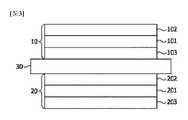
本出願は偏光板に関する。図1は、本出願の偏光板を例示的に示す。図1に示した通り、前記偏光板は第1保護フィルム102、偏光子101および第2保護フィルム103を順に含むことができる。すなわち、偏光子101の両面にはそれぞれ第1保護フィルム102および第2保護フィルム103が配置され得る。 This application relates to polarizers. FIG. 1 exemplarily shows the polarizing plate of the present application. As shown in FIG. 1, the polarizing plate may include a first
本明細書で用語偏光子は偏光機能を有するフィルム、シートまたは素子を意味する。偏光子は多様な方向に振動する入射光から一方向に振動する光を抽出できる機能性素子である。 As used herein, the term polarizer means a film, sheet or element having a polarizing function. A polarizer is a functional element that can extract light oscillating in one direction from incident light oscillating in various directions.
前記偏光子は吸収型偏光子であり得る。本明細書で吸収型偏光子は入射光に対して選択的透過および吸収特性を示す素子を意味する。前記偏光子は線偏光子であり得る。前記吸収型偏光子は多様な方向に振動する入射光からいずれか一方向に振動する光は透過し、残りの方向に振動する光は吸収することができる。 The polarizer may be an absorptive polarizer. Absorptive polarizers, as used herein, refer to elements that exhibit selective transmission and absorption characteristics for incident light. The polarizer may be a linear polarizer. The absorptive polarizer can transmit light oscillating in one direction from incident light oscillating in various directions and absorb light oscillating in the remaining directions.
前記偏光子は線偏光子であり得る。本明細書で線偏光子は、選択的に透過する光がいずれか一方向に振動する線偏光であり、選択的に吸収する光が前記線偏光の振動方向と直交する方向に振動する線偏光である偏光子を意味する。 The polarizer may be a linear polarizer. In this specification, the linear polarizer is a linearly polarized light in which selectively transmitted light vibrates in one direction, and a linearly polarized light in which selectively absorbed light vibrates in a direction orthogonal to the vibration direction of the linearly polarized light. means a polarizer that is
前記偏光子としては、例えば、PVA延伸フィルムなどのような高分子延伸フィルムにヨウ素を染着した偏光子または配向された状態で重合された液晶をホストとし、前記液晶の配向に沿って配列された異方性染料をゲストとするゲスト‐ホスト型偏光子を使用できるがこれに制限されるものではない。 As the polarizer, for example, a polarizer obtained by dyeing a stretched polymer film such as a stretched PVA film with iodine, or a liquid crystal polymerized in an oriented state as a host and aligned along the orientation of the liquid crystal. A guest-host polarizer with an anisotropic dye as a guest can be used, but is not limited to this.
本出願の一実施例によると、前記偏光子としてはPVA延伸フィルムを使うことができる。前記偏光子の透過率乃至偏光度は、本出願の目的を考慮して適切に調節され得る。例えば前記偏光子の透過率は41.5%~55%であり得、偏光子の偏光度は65%~99.9999%であり得る。 According to an embodiment of the present application, a stretched PVA film can be used as the polarizer. The transmittance or degree of polarization of the polarizer can be appropriately adjusted in consideration of the purpose of the present application. For example, the transmittance of the polarizer may be 41.5% to 55%, and the degree of polarization of the polarizer may be 65% to 99.9999%.
第1保護フィルムと第2保護フィルムのうち一つ以上の保護フィルムは、その保護フィルムのTD(Transverse Direction)軸に対して遅相軸(Slow axis)がなす角度が0度~4.5度の範囲内であり得る。このようなTD軸と遅相軸の関係を有する保護フィルムの使用を通じて、偏光サングラスを着用してディスプレイ装置を観察する時、色相歪曲を防止することができる。本明細書で前記TD軸と遅相軸の関係を有する保護フィルムを「色相歪曲防止用保護フィルム」と呼称し得る。 At least one of the first protective film and the second protective film has an angle of 0 to 4.5 degrees between the slow axis and the TD (Transverse Direction) axis of the protective film. can be in the range of Through the use of the protective film having the relationship between the TD axis and the slow axis, it is possible to prevent color distortion when viewing the display device while wearing polarized sunglasses. In the present specification, the protective film having the relationship between the TD axis and the slow axis may be referred to as "a protective film for preventing hue distortion".
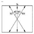
図2は、色相歪曲防止用保護フィルムのTD軸に対して遅相軸がなす角度の関係を例示的に示す。図2で角度a(+)はTD軸(TD)に対して遅相軸(S(+))が時計回り方向になす角度を意味し、角度a(-)はTD軸(TD)に対して遅相軸(S(-))が反時計回り方向になす角度を意味する。 FIG. 2 exemplarily shows the relationship of the angle between the slow axis and the TD axis of the protective film for preventing color distortion. In FIG. 2, the angle a(+) means the angle formed by the slow axis (S(+)) in the clockwise direction with respect to the TD axis (TD), and the angle a(−) means the angle with respect to the TD axis (TD). means the angle formed by the slow axis (S(-)) in the counterclockwise direction.
本明細書で基準軸(例えば、TD軸)に対して遅相軸が時計回り方向になす角度は「+」符号で表示することができ、反時計回り方向になす角度は「-」符号で表示することができる。本明細書で角度について記載する時に、その角度の符号乃至方向を特に指定しない場合、時計回り方向または反時計回り方向になす角度をすべて含む意味であるかまたはその角度の大きさだけを意味し得る。図2では、TD軸に対して遅相軸がなす角度の範囲を時計回り方向または反時計回り方向に説明するために便宜上遅相軸をS(+)およびS(-)で表示したが、一つの保護フィルムは面上において一つの遅相軸を有する。 Herein, the angle formed by the slow axis in the clockwise direction with respect to the reference axis (e.g., the TD axis) can be indicated by a "+" sign, and the angle formed in the counterclockwise direction by a "-" sign. can be displayed. When describing an angle in this specification, if the sign or direction of the angle is not specified, it means all angles formed in the clockwise or counterclockwise direction or only the magnitude of the angle. obtain. In FIG. 2, the slow axis is indicated by S (+) and S (-) for convenience in order to explain the range of angles formed by the slow axis with respect to the TD axis in the clockwise or counterclockwise direction. One protective film has one slow axis on the surface.
本明細書で遅相軸(Slow axis)は保護フィルムの面上で屈折率が最も高い方向の軸を意味し得る。本明細書で進相軸(Fast axis)は保護フィルムの面上で屈折率が最も低い方向の軸を意味し得、前記遅相軸と垂直となり得る。 As used herein, the slow axis may mean the axis in the direction of the highest refractive index on the surface of the protective film. In the present specification, the fast axis may mean the axis in the direction of the lowest refractive index on the surface of the protective film, and may be perpendicular to the slow axis.
本明細書で縦方向(MD:Machine Direction)はフィルムを形成するための機械の進行方向またはフィルムの長さ方向を意味し得、横方向(TD:Transverse Direction)は前記機械の進行方向に垂直な方向またはフィルムの幅方向を意味し得る。通常的に、押出されたフィルムはTD軸がMD軸に比べて、引張強度がより高い傾向がある。したがって、保護フィルムの引張強度を測定することによって、TD軸を確認することもできる。 Machine direction (MD) herein may mean the direction of travel of a machine for forming a film or the longitudinal direction of a film, and transverse direction (TD) is perpendicular to the direction of travel of said machine. direction or across the width of the film. Generally, extruded films tend to have higher tensile strength in the TD axis than in the MD axis. Therefore, the TD axis can also be confirmed by measuring the tensile strength of the protective film.
一つの例として、色相歪曲防止用保護フィルムはTD軸に対して遅相軸がなす角度が例えば、0度~4度、0度~3.5度または0度~3度の範囲内であり得る。このような角度範囲内で偏光サングラスを着用してディスプレイ装置を観察する時に色相歪曲を防止することがさらに有利であり得る。 As one example, in the protective film for preventing hue distortion, the angle formed by the slow axis with respect to the TD axis is, for example, within the range of 0 to 4 degrees, 0 to 3.5 degrees, or 0 to 3 degrees. obtain. It may be more advantageous to prevent color distortion when viewing the display device while wearing polarized sunglasses within such an angular range.
一つの例として、色相歪曲防止用保護フィルムはTD軸に対して遅相軸がなす角度が時計回り方向に0度~4.5、0度~4度、0度~3.5度または0度~3度であり得る。他の一つの例として、色相歪曲防止用保護フィルムはTD軸に対して遅相軸がなす角度が反時計回り方向に0度~4.5、0度~4度、0度~3.5度または0度~3度であり得る。 As one example, in the protective film for preventing hue distortion, the angle formed by the slow axis with respect to the TD axis is 0 degrees to 4.5 degrees, 0 degrees to 4 degrees, 0 degrees to 3.5 degrees, or 0 degrees in the clockwise direction. degrees to 3 degrees. As another example, in the protective film for preventing hue distortion, the angle formed by the slow axis with respect to the TD axis is 0 degrees to 4.5 degrees, 0 degrees to 4 degrees, and 0 degrees to 3.5 degrees in the counterclockwise direction. degrees or 0 degrees to 3 degrees.
一つの例として、第1保護フィルムと第2保護フィルムのうちいずれか一つの保護フィルムは、色相歪曲防止用保護フィルムであり得る。この場合、残りの一つの保護フィルムは偏光子の通常的な保護フィルムを使うことができる。偏光子の通常的な保護フィルムとしては、TAC(Triacetyl cellulose)フィルムなどのようなセルロースフィルム;PET(poly(ethylene terephthalate))フィルムなどのようなポリエステルフィルム;ポリカーボネートフィルム;ポリエーテルスルホンフィルム;アクリルフィルムおよび/またはポリエチレンフィルム、ポリプロピレンフィルム、シクロ系やノルボルネン構造を含むポリオレフィンフィルムまたはエチレン‐プロピレン共重合体フィルムなどのポリオレフィン系フィルムなどを使用できるが、これに制限されるものではない。偏光子の通常的な保護フィルムは光学等方性フィルムまたは光学異方性フィルムであり得る。光学異方性フィルムである場合、前記TD軸と遅相軸の関係を有さないか、後述する面内位相差値を有さなくてもよい。他の一つの例として、第1保護フィルムと第2保護フィルムは両方とも色相歪曲防止用保護フィルムであり得る。この場合、第1保護フィルムのTD軸と第2保護フィルムのTD軸は互いに平行し得る。 For example, one of the first protective film and the second protective film may be a protective film for preventing color distortion. In this case, the remaining one protective film can be a common protective film for polarizers. Common protective films for polarizers include cellulose films such as TAC (triacetyl cellulose) films; polyester films such as PET (poly(ethylene terephthalate)) films; polycarbonate films; polyethersulfone films; And/or a polyethylene film, a polypropylene film, a polyolefin film containing a cyclo- or norbornene structure, or a polyolefin-based film such as an ethylene-propylene copolymer film can be used, but not limited thereto. A typical protective film for a polarizer can be an optically isotropic film or an optically anisotropic film. In the case of an optically anisotropic film, it may not have a relationship between the TD axis and the slow axis, or may not have an in-plane retardation value to be described later. As another example, both the first protective film and the second protective film may be protective films for preventing color distortion. In this case, the TD axis of the first protective film and the TD axis of the second protective film may be parallel to each other.
一つの例示において、色相歪曲防止用保護フィルムはポリエステルフィルムであり得る。一つの例として、前記ポリエステルフィルムはポリエチレンテレフタレートフィルム(PETフィルム)であり得る。これを通じて、偏光子の保護フィルムにより外部環境、例えば、水分に対する耐久性が優秀であり、偏光サングラスを着用して観察時に色相歪曲を防止できる偏光板を提供することができる。 In one example, the protective film for preventing color distortion may be a polyester film. As one example, the polyester film may be a polyethylene terephthalate film (PET film). Through this, it is possible to provide a polarizing plate that has excellent durability against an external environment such as moisture due to the protective film of the polarizer and that can prevent color distortion when wearing polarized sunglasses.
前記PETフィルムとしては延伸PETフィルムを使うことができる。延伸PETフィルムとしては例えば、1種以上のPET系樹脂を溶融押出あるいは溶媒を利用した溶解押出によって製膜し、横に延伸してなる一層以上の一軸延伸フィルム、または製膜後に縦および横延伸を利用してなる一層以上の二軸延伸フィルム、または斜線方向の延伸を利用した斜線延伸フィルムを使うことができる。 A stretched PET film can be used as the PET film. Examples of stretched PET films include one or more uniaxially stretched films obtained by forming a film from one or more PET-based resins by melt extrusion or solution extrusion using a solvent, and then stretching the film horizontally, or after forming the film, stretching it vertically and horizontally. or a diagonally stretched film utilizing diagonal stretching.
PET系樹脂は繰り返し単位の80モル%以上がエチレンテレフタレートで構成される樹脂を意味し、他のジカルボン酸成分とジオール成分を含んでもよい。他のジカルボン酸成分としては、特に限定されるものではないが、例えばイソフタル酸、p‐β‐オキシエトキシ安息香酸、4,4’‐ジカルボキシジフェニル、4,4’‐ジカルボキシベンゾフェノン、ビス(4‐カルボキシフェニル)エタン、アジフ酸、セバシン酸および1,4‐ジカルボキシシクロヘキサンなどが挙げられる。他のジオール成分としては、特に限定されるものではないが、プロピレングリコール、ブタンジオール、ネオペンチルグリコール、ジエチレングリコール、シクロヘキサンジオール、ビスフェノールAのエチレンオキサイド付加物、ポリエチレングリコール、ポリプロピレングリコールおよびポリテトラメチレングリコールなどが挙げられる。これら他のジカルボン酸成分や他のジオール成分は必要に応じて2種以上を組み合わせて使うことができる。また、p‐オキシ安息香酸などのオキシカルボン酸を併用することもできる。また、他の共重合成分として、少量のアミド結合、ウレタン結合、エーテル結合およびカーボネート結合などを含有するジカルボン酸成分、またはジオール成分が利用され得る。 The PET resin means a resin in which 80 mol % or more of the repeating units is composed of ethylene terephthalate, and may contain other dicarboxylic acid component and diol component. Other dicarboxylic acid components include, but are not limited to, isophthalic acid, p-β-oxyethoxybenzoic acid, 4,4′-dicarboxydiphenyl, 4,4′-dicarboxybenzophenone, bis( 4-carboxyphenyl)ethane, adipic acid, sebacic acid and 1,4-dicarboxycyclohexane. Other diol components include, but are not limited to, propylene glycol, butanediol, neopentyl glycol, diethylene glycol, cyclohexanediol, ethylene oxide adducts of bisphenol A, polyethylene glycol, polypropylene glycol and polytetramethylene glycol. is mentioned. These other dicarboxylic acid components and other diol components can be used in combination of two or more if necessary. In addition, oxycarboxylic acid such as p-oxybenzoic acid can be used together. Also, as other copolymerization components, a dicarboxylic acid component containing a small amount of amide bond, urethane bond, ether bond, carbonate bond, etc., or a diol component can be used.
PET系樹脂の製造方法としては、テレフタル酸およびエチレングリコール(および必要に応じて他のジカルボン酸または他のジオール)を直接重縮合させる方法、テレフタル酸のジアルキルエステルおよびエチレングリコール(および必要に応じて他のジカルボン酸のジアルキルエステルまたは他のジオール)をエステル交換反応させた後に重縮合させる方法、およびテレフタル酸(および必要に応じて他のジカルボン酸)のエチレングリコールエステル(および必要に応じて他のジオールエステル)を重縮合させる方法などが採用される。 Methods for producing PET resins include direct polycondensation of terephthalic acid and ethylene glycol (and optionally other dicarboxylic acids or other diols), dialkyl esters of terephthalic acid and ethylene glycol (and optionally dialkyl esters of other dicarboxylic acids or other diols) by transesterification followed by polycondensation, and ethylene glycol esters of terephthalic acid (and optionally other dicarboxylic acids) (and optionally other A method of polycondensing a diol ester) is adopted.
それぞれの重合反応には、アンチモン系、チタン系、ゲルマニウム系またはアルミニウム系化合物を含む重合触媒、または前記複合化合物を含む重合触媒を使うことができる。 For each polymerization reaction, a polymerization catalyst containing an antimony, titanium, germanium, or aluminum compound, or a polymerization catalyst containing the composite compound can be used.
前記重合反応条件は、使われる単量体、触媒、反応装置および目的とする樹脂の物性に応じて適切に選択することができ、特に制限されるものではないが、例えば反応温度は通常約150℃~約300℃、約200℃~約300℃または約260℃~約300℃であり得る。また、反応圧力は通常大気圧乃至約2.7Paであり得、その中でも反応の後半には減圧側であることが好ましい。 The polymerization reaction conditions can be appropriately selected according to the monomers, catalysts, reactors and physical properties of the desired resin, and are not particularly limited. °C to about 300 °C, about 200 °C to about 300 °C, or about 260 °C to about 300 °C. Moreover, the reaction pressure can be usually atmospheric pressure to about 2.7 Pa, and among them, it is preferably on the reduced pressure side in the second half of the reaction.
重合反応はこのような高温・高減圧条件下で攪拌されることによって、ジオール、アルキル化合物または水などの離脱反応物を揮発させることによって進行され得る。 The polymerization reaction can proceed by volatilizing the leaving reactants such as diols, alkyl compounds or water by stirring under such high temperature and high pressure conditions.
また、重合装置は反応槽が一つで完結するものでもよく、または複数の反応槽を連結したものでもよい。この場合、通常、重合度により反応物は反応槽間を移送されながら重合される。また、重合後半に横型反応装置を具備し、加熱・混練しながら揮発させる方法も採用することができる。 Moreover, the polymerization apparatus may be completed with a single reaction vessel, or may be one in which a plurality of reaction vessels are connected. In this case, the reactants are usually polymerized while being transported between reactors depending on the degree of polymerization. Moreover, a method of equipping a horizontal reactor in the second half of the polymerization and volatilizing while heating and kneading can also be adopted.
重合終了後の樹脂は、溶融状態で反応槽や横型反応装置から放出された後、冷却ドラムや冷却ベルトなどで冷却・粉砕されたフレーク状の形態で、または押出機に導入されて紐状に押出された後に裁断されたペレット状の形態で得られ得る。また、必要に応じて固相重合を行って、分子量を向上させるか低分子量成分を減少させてもよい。PET系樹脂に含まれ得る低分子量成分としては、環状3量体成分が挙げられるが、このような環状3量体成分の樹脂中での含量は5000ppm以下であることが好ましく、3000ppm以下であることがより好ましい。環状3量体成分が5000ppmを超過すると、フィルムの光学的物性に悪影響を及ぼす場合がある。 After completion of polymerization, the resin is discharged from the reactor or horizontal reactor in a molten state, then cooled and pulverized by a cooling drum or cooling belt in the form of flakes, or introduced into an extruder and formed into a string. It can be obtained in pellet-like form which is extruded and then chopped. Solid state polymerization may also be carried out, if desired, to increase molecular weight or reduce low molecular weight components. Low-molecular-weight components that can be contained in the PET-based resin include cyclic trimer components, and the content of such cyclic trimer components in the resin is preferably 5000 ppm or less, and is 3000 ppm or less. is more preferable. When the cyclic trimer component exceeds 5000 ppm, the optical properties of the film may be adversely affected.
PET系樹脂の分子量は、フェノール/テトラクロロエタン=50/50(重量比)の混合溶媒に樹脂を溶解させ、30℃で測定した極限粘度で表したとき、通常0.45~1.0dL/g、0.50~1.0dL/gまたは0.52~0.80dL/gの範囲内であり得る。極限粘度が0.45dL/g未満である場合、フィルム製造時の生産性が低下したりフィルムの機械的強度が低下したりし得る。また、極限粘度が1.0dL/gを超過する場合、フィルムの製造においての重合体の溶融押出安定性が劣悪となり得る。 The molecular weight of the PET resin is usually 0.45 to 1.0 dL/g when the resin is dissolved in a mixed solvent of phenol/tetrachloroethane = 50/50 (weight ratio) and represented by the intrinsic viscosity measured at 30°C. , 0.50-1.0 dL/g or 0.52-0.80 dL/g. When the intrinsic viscosity is less than 0.45 dL/g, the productivity during film production may be lowered and the mechanical strength of the film may be lowered. In addition, if the intrinsic viscosity exceeds 1.0 dL/g, the melt extrusion stability of the polymer during film production may be poor.
また、PET系樹脂は必要に応じて添加剤を含有することができる。添加剤としては、例えば潤滑剤、ブロッキング防止剤、熱安定剤、酸化防止剤、帯電防止剤、耐光剤および耐衝撃性改良剤などが挙げられる。その添加量は光学物性に悪影響を及ぼさない範囲にすることが好ましい。 Moreover, the PET-based resin can contain additives as necessary. Additives include, for example, lubricants, antiblocking agents, heat stabilizers, antioxidants, antistatic agents, light stabilizers and impact modifiers. The amount added is preferably within a range that does not adversely affect optical properties.
PET系樹脂はこのような添加剤の配合のために、または後述するフィルム成形のために、通常押出機によって組み立てられたペレット状で利用され得る。ペレットの大きさや形状は特に制限されるものではないが、一般的に高さ、直径が共に5mm以下の円柱状、球状または扁平な球状であり得る。このようにして得られるPET系樹脂をフィルム状に成形し、延伸処理することによって、透明で均質な機械的強度が高いPETフィルムを得ることができる。その製造方法としては、特に限定されるものではないが、例えば次に記載する方法が適用され得る。 PET-based resins can be used in the form of pellets usually assembled by an extruder for compounding such additives or for film forming, which will be described later. The size and shape of the pellets are not particularly limited, but generally they may be columnar, spherical or flattened spherical with a height and a diameter of 5 mm or less. By forming the PET-based resin obtained in this manner into a film and stretching the film, a transparent, homogeneous PET film having high mechanical strength can be obtained. The manufacturing method thereof is not particularly limited, but for example, the method described below can be applied.
まず、乾燥させたPET樹脂からなるペレットを溶融押出装置に供給し、融点以上に加熱して溶融させる。次いで、溶融した樹脂をダイから押出、回転冷却ドラム上でガラス転移温度以下の温度となるように急冷して固化させて、実質的に非結晶状態の未延伸フィルムを得ることができる。この溶融温度は使われるPET系樹脂の融点や押出機によって決定されるものであり、特に制限されるものではないが、通常250~350℃であり得る。また、フィルムの平面性を向上させるためには、フィルムと回転冷却ドラムとの密着性を高めることが好ましく、静電印加密着法または液体塗布密着法を採用することができる。静電印加密着法とは、通常フィルムの上面側にフィルムの流れと直交する方向に線状電極を設置し、その電極に約5~10kVの直流電圧を印加することによってフィルムに静電荷を提供して、回転冷却ドラムとフィルムとの密着性を向上させる方法である。また、液体塗布密着法とは、回転冷却ドラムの表面全体または一部(例えばフィルムの両端部と接触する部分のみ)に液体を均一に塗布することによって、回転冷却ドラムとフィルムとの密着性を向上させる方法である。必要に応じて両者を併用してもよい。使われるPET系樹脂は、必要に応じて2種以上の樹脂構造や組成が異なる樹脂を混合してもよい。例えば、ブロッキング防止剤としての粒状充填材、紫外線吸収剤または帯電防止剤などが配合されたペレットと、無配合のペレットを混合して利用するものなどが挙げられる。 First, pellets made of dried PET resin are supplied to a melt extruder and melted by heating to a melting point or higher. Then, the molten resin is extruded from a die and solidified by quenching to a temperature below the glass transition temperature on a rotating cooling drum to obtain a substantially amorphous unstretched film. This melting temperature is determined by the melting point of the PET resin used and the extruder, and is not particularly limited, but it is usually 250 to 350°C. Further, in order to improve the flatness of the film, it is preferable to increase the adhesion between the film and the rotating cooling drum, and an electrostatic application adhesion method or a liquid coating adhesion method can be employed. In the electrostatic application adhesion method, a linear electrode is usually installed on the upper surface of the film in a direction perpendicular to the flow of the film, and an electrostatic charge is applied to the film by applying a DC voltage of about 5 to 10 kV to the electrode. This is a method for improving the adhesion between the rotating cooling drum and the film. In addition, the liquid application adhesion method is a method in which a liquid is evenly applied to the entire surface or part of the surface of the rotating cooling drum (for example, only the portions that come into contact with both ends of the film), thereby improving the adhesion between the rotating cooling drum and the film. It's a way to improve. You may use both together as needed. As for the PET-based resin to be used, two or more resins having different resin structures or compositions may be mixed, if necessary. For example, pellets containing a granular filler as an anti-blocking agent, an ultraviolet absorber, an antistatic agent, etc., and unblended pellets are mixed and used.
また、押出させるフィルムの積層数は必要に応じて2層以上としてもよい。例えば、ブロッキング防止剤への粒状充填材を配合したペレットと無配合のペレットを準備し、他の押出機から同じダイに供給して「充填材配合/無配合/充填材配合」の2種3層からなるフィルムを押出させるものなどが挙げられる。 Moreover, the number of layers of films to be extruded may be two or more as required. For example, prepare pellets mixed with granular fillers and unblended pellets for anti-blocking agents, supply them from another extruder to the same die, and supply two types of "filler blended / unblended / filled with filler" 3 Examples include those in which a film consisting of layers is extruded.
前記未延伸フィルムはガラス転移温度以上の温度で通常、優先押出方向に延伸される。延伸温度は通常70~150℃、80~130℃または90~120℃であり得る。また、延伸倍率は通常1.1~6倍または2~5.5倍であり得る。延伸倍率が1.1倍未満であると、延伸PETフィルムの機械的強度が足りない傾向がある可能性がある。延伸倍率が6倍を超過すると、横方向の強度が実際に使うのに不足し得る。この延伸は1回で終えてもよく、必要に応じて複数回に分けて行ってもよい。通常、複数回の延伸を行う場合にも、銃延伸倍率は前記範囲であることが好ましい。 The unstretched film is typically stretched in the preferred extrusion direction at a temperature above the glass transition temperature. The stretching temperature can usually be 70-150°C, 80-130°C or 90-120°C. Also, the draw ratio can be usually 1.1 to 6 times or 2 to 5.5 times. If the draw ratio is less than 1.1 times, the stretched PET film may tend to have insufficient mechanical strength. If the draw ratio exceeds 6 times, the transverse strength may be insufficient for practical use. This stretching may be completed in one step, or may be performed in multiple steps as necessary. Generally, even when the film is drawn a plurality of times, the gun draw ratio is preferably within the above range.
このようにして得られる縦延伸フィルムは、この後に熱処理を行うことができる。引き続き、必要に応じて弛緩処理を行ってもよい。子の熱処理温度は通常150~250℃、180~245℃または200~230℃であり得る。また、熱処理時間は通常1~600秒、1~300秒または1~60秒であり得る。弛緩処理温度は通常90~200℃または120~180℃であり得る。また、弛緩量は通常0.1~20%または2~5%であり得る。前記弛緩処理の温度および弛緩量は、弛緩処理後のPETフィルムの150℃での熱収縮率が2%以下となるように、その弛緩量および弛緩処理時の温度を設定することが好ましい。 The longitudinally stretched film thus obtained can be subjected to heat treatment after this. Subsequently, relaxation treatment may be performed as necessary. The heat treatment temperature of the child can usually be 150-250°C, 180-245°C or 200-230°C. Also, the heat treatment time can be usually 1 to 600 seconds, 1 to 300 seconds or 1 to 60 seconds. The relaxation treatment temperature can usually be 90-200°C or 120-180°C. Also, the amount of relaxation can usually be 0.1-20% or 2-5%. The temperature and amount of relaxation are preferably set so that the thermal shrinkage of the PET film at 150° C. after relaxation is 2% or less.
一軸延伸および二軸延伸フィルムを得る場合、通常縦延伸処理後に、または必要に応じて熱処理または弛緩処理を経た後に、テンターによって横延伸が行われ得る。この延伸温度は通常70~150℃、80~130℃または90~120℃であり得る。また、延伸倍率は通常1.1~6倍または2~5.5倍であり得る。横延伸においての延伸倍率が1.1倍未満であると、配向によるフィルム強度向上が不足し得る。また、6倍を超過する延伸倍率は製造技術上現実的ではない。 In the case of obtaining uniaxially stretched and biaxially stretched films, transverse stretching can be carried out by a tenter, usually after longitudinal stretching, or optionally after heat treatment or relaxation treatment. The stretching temperature can usually be 70-150°C, 80-130°C or 90-120°C. Also, the draw ratio can be usually 1.1 to 6 times or 2 to 5.5 times. If the stretch ratio in the lateral stretching is less than 1.1 times, the improvement in film strength due to orientation may be insufficient. Moreover, a draw ratio exceeding 6 times is not realistic from the standpoint of manufacturing technology.
この後、熱処理および必要に応じて弛緩処理を行うことができる。熱処理温度は通常150~250℃、180~245℃または200~230℃であり得る。熱処理時間は通常1~600秒、1~300秒または1~60秒であり得る。弛緩処理の温度は通常100~230℃、110~210℃または120~180℃であり得る。また、弛緩量は通常0.1~20%、1~10%または2~5%であり得る。この弛緩処理の温度および弛緩量は、弛緩処理後のPETフィルムの150℃での熱収縮率が2%以下となるように、その弛緩量および弛緩処理時の温度を設定することが好ましい。 This can be followed by heat treatment and, if necessary, relaxation treatment. The heat treatment temperature can usually be 150-250°C, 180-245°C or 200-230°C. The heat treatment time can typically be 1-600 seconds, 1-300 seconds or 1-60 seconds. The temperature of the relaxation treatment can usually be 100-230°C, 110-210°C or 120-180°C. Also, the amount of relaxation can usually be 0.1-20%, 1-10% or 2-5%. The temperature and amount of relaxation are preferably set so that the thermal shrinkage of the PET film at 150° C. after relaxation is 2% or less.
一軸延伸および二軸延伸処理においては、両者ともその延伸処理温度が250℃を超過すると、樹脂に熱劣化が発生したり、結晶化が過度に進行されたりするため、光学性能が低下する場合がある。また、延伸処理温度が70℃未満になると、延伸に過大なストレスがかかるか、フィルムが固化して延伸自体が不可能となり得る。 In both uniaxial stretching and biaxial stretching, if the stretching temperature exceeds 250°C, the resin may be thermally degraded or crystallized excessively, resulting in a decrease in optical performance. be. On the other hand, if the stretching temperature is lower than 70° C., excessive stress may be applied to the stretching, or the film may solidify, making stretching itself impossible.
また、一軸延伸および二軸延伸処理においては、横延伸後、ボーイングで代表されるような配向主軸の変形を緩和させるために、再度熱処理を行うか延伸処理を行うことができる。ボーイングによる配向主軸の延伸方向に対する変形の最大値は通常45°以内であるが、30°以内に緩和させることが好ましく、15°以内にすることがより好ましい。配向主軸の変形の最大値が45°を超過すると、以降の工程で偏光板を構成して枚葉化された時に、この枚葉間で光学特性の不均一が発生する場合がある。また、ここで延伸方向とは、縦延伸または横延伸においての延伸が大きい方向を指す。 In uniaxial stretching and biaxial stretching, after transverse stretching, heat treatment or stretching may be carried out again in order to relax the deformation of the main axis of orientation such as bowing. The maximum value of deformation of the principal axis of orientation with respect to the stretching direction due to bowing is usually within 45°, preferably within 30°, more preferably within 15°. If the maximum value of deformation of the principal axis of orientation exceeds 45°, non-uniformity in optical properties may occur between sheets when polarizing plates are formed in subsequent steps and sheeted. The term "stretching direction" as used herein refers to a direction in which stretching is greater in longitudinal stretching or transverse stretching.
PETフィルムの二軸延伸では、通常横延伸倍率が縦延伸倍率より若干大きく行われるため、この場合、延伸方向とは、前記フィルムの長さ方向に対して垂直方向を意味し得る。また、一軸延伸では、通常前記したように横方向に延伸されるため、この場合、延伸方向とは、同様に長さ方向に対して垂直方向を意味する。 In the biaxial stretching of a PET film, the transverse stretching ratio is generally slightly larger than the longitudinal stretching ratio, so in this case the stretching direction may mean the direction perpendicular to the length direction of the film. In the case of uniaxial stretching, since the film is generally stretched in the horizontal direction as described above, the stretching direction in this case also means the direction perpendicular to the length direction.
また、ここで配向主軸とは、延伸PETフィルム上の任意の点での分子の配向方向を意味する。また、配向主軸の延伸方向に対する変形とは、配向主軸と延伸方向との角度差を意味する。また、その最大値とは、長さ方向に対して垂直方向上での値の最大値を意味する。 In addition, the term "orientation principal axis" as used herein means the orientation direction of molecules at an arbitrary point on the stretched PET film. Further, the deformation of the main orientation axis with respect to the stretching direction means the angle difference between the main orientation axis and the stretching direction. The maximum value means the maximum value in the direction perpendicular to the length direction.
前記配向主軸は、例えば位相差フィルム・光学材料検査装置RETS(大塚電子株式会社製造)または分子配向系MOA(王子計測機器株式会社製造)を利用して測定することができる。 The main axis of orientation can be measured using, for example, a retardation film/optical material inspection system RETS (manufactured by Otsuka Electronics Co., Ltd.) or a molecular orientation system MOA (manufactured by Oji Scientific Instruments Co., Ltd.).
前記延伸PETフィルムが偏光板の視認側に利用される場合、防眩性(ヘイズ)が付与されていてもよい。防眩性を付与する方法は特に限定されるものではないが、例えば前記原料樹脂中に無機微粒子または有機微粒子を混合してフィルム化する方法、前記多層フィルムの製造方法に準じて、一側に無機微粒子または有機微粒子が混合された層を有する未延伸フィルムから延伸フィルム化する方法、または延伸PETフィルムの一側に、無機微粒子または有機微粒子を硬化性バインダー樹脂に混合してなる塗布液をコーティングし、バインダー樹脂を硬化して防眩層を設置する方法などが採用され得る。 When the stretched PET film is used on the viewing side of the polarizing plate, it may be provided with antiglare properties (haze). The method for imparting antiglare property is not particularly limited, but for example, a method of mixing inorganic fine particles or organic fine particles into the raw material resin to form a film, a method of producing a multilayer film according to the method of producing a multilayer film, A method of forming a stretched film from an unstretched film having a layer in which inorganic fine particles or organic fine particles are mixed, or coating one side of a stretched PET film with a coating liquid obtained by mixing inorganic fine particles or organic fine particles with a curable binder resin. Alternatively, a method of curing a binder resin to form an antiglare layer may be adopted.
防眩性を付与するための無機微粒子としては、特に限定されるものではないが、例えばシリカ、コロイダルシリカ、アルミナ、アルミナゾル、アルミノシリケート、アルミナ‐シリカ複合酸化物、カオリン、タルク、雲母、炭酸カルシウムおよびリン酸カルシウムなどが挙げられる。また、有機微粒子としては、特に限定されるものではないが、例えば架橋ポリアクリル酸粒子、メタクリル酸メチル/スチレン共重合体樹脂粒子、架橋ポリスチレン粒子、架橋ポリメチルメタクリレート粒子、シリコン樹脂粒子およびポリイミド粒子などが挙げられる。 The inorganic fine particles for imparting antiglare properties are not particularly limited, but examples include silica, colloidal silica, alumina, alumina sol, aluminosilicate, alumina-silica composite oxide, kaolin, talc, mica, and calcium carbonate. and calcium phosphate. The organic fine particles are not particularly limited, but for example, crosslinked polyacrylic acid particles, methyl methacrylate/styrene copolymer resin particles, crosslinked polystyrene particles, crosslinked polymethyl methacrylate particles, silicone resin particles and polyimide particles. etc.
前記防眩性が付与された延伸PETフィルム上には、導電層、ハードコーティング層および低反射層などの機能層をさらに積層することができる。また、前記防眩層を構成する樹脂組成物として、これらのうちいずれか一つの機能を兼ね備える樹脂組成物を選択してもよい。 Functional layers such as a conductive layer, a hard coating layer and a low reflection layer can be further laminated on the stretched PET film to which the antiglare property has been imparted. As the resin composition constituting the antiglare layer, a resin composition having any one of these functions may be selected.
一方、延伸PETフィルムが偏光板のバックライト側に利用される場合、防眩性はあえて付与しなくてもよい。この場合、そのヘイズ値は通常6%未満であり得る。しかし、防眩性を付与しなくても、前記機能層を積層することができる。 On the other hand, when the stretched PET film is used on the backlight side of the polarizing plate, antiglare properties need not be imparted. In this case, the haze value can typically be less than 6%. However, the functional layer can be laminated without imparting antiglare properties.
前記ヘイズ値はJIS K 7136に準拠して、例えばヘイズ・透過率計HM-150(株式会社村上色彩技術研究所製造)を利用して測定することができる。 The haze value can be measured according to JIS K 7136, for example, using a haze/transmittance meter HM-150 (manufactured by Murakami Color Research Laboratory).
前記延伸PETフィルムには、本発明の効果を妨げない限り、前記防眩層以外の機能層を一側面または両面に積層することができる。積層される機能層には、例えば導電層、ハードコーティング層、平滑化層、易滑化層、ブロッキング防止層および易接着層などが挙げられる。その中でも、延伸PETフィルムは偏光フィルムと接着剤層を通じて積層され得るため、易接着層が積層されていることが好ましい。 A functional layer other than the antiglare layer can be laminated on one or both sides of the stretched PET film as long as the effect of the present invention is not hindered. Functional layers to be laminated include, for example, a conductive layer, a hard coating layer, a smoothing layer, an easy-to-smooth layer, an anti-blocking layer and an easy-adhesion layer. Among these, since the stretched PET film can be laminated through the polarizing film and the adhesive layer, it is preferable that the easy-adhesion layer is laminated.
易接着層を構成する成分は特に限定されるものではないが、例えば極性基を骨格に有し、比較的低分子量で低ガラス転移温度であるポリエステル系樹脂、ウレタン系樹脂またはアクリル系樹脂などが挙げられる。また、必要に応じて架橋剤、有機または無機充填材、界面活性剤および潤滑剤などを含有することができる。 The component that constitutes the easy-adhesion layer is not particularly limited, but for example, it has a polar group in its skeleton, and has a relatively low molecular weight and a low glass transition temperature, such as a polyester resin, a urethane resin, or an acrylic resin. mentioned. It may also contain cross-linking agents, organic or inorganic fillers, surfactants, lubricants, and the like, if necessary.
前記機能層を延伸PETフィルムに形成する方法は特に限定されるものではないが、例えばすべての延伸工程が終了したフィルムに形成する方法、PET系樹脂を延伸している工程中に、例えば縦延伸と横延伸工程の間に形成する方法、および偏光子と接着される直前または接着された後に形成する方法などが採用され得る。その中でも生産性の観点では、PET系樹脂を縦延伸した後に形成し、引き続き横延伸する方法が好ましく採用され得る。 The method of forming the functional layer on the stretched PET film is not particularly limited. and a method of forming the film during the lateral stretching step, a method of forming the film immediately before or after bonding with the polarizer, and the like. Among them, from the viewpoint of productivity, a method of longitudinally stretching the PET-based resin, forming the film, and then laterally stretching can be preferably employed.
このようにして得られる延伸PETフィルムは市販品を容易に入手可能であり、例えばそれぞれ商品名で「ダイアホイル」、「ホスタファン」、「フュージョン」(以上、三菱樹脂株式会社製造)、「帝人テトロンフィルム」、「メリネックス」、「マイラー」、「テプレックス」(以上、帝人デュポンフィルム株式会社製造)、「東洋紡エステルフィルム」、「東洋紡エスペットフィルム」、「コスモシャイン」、「クリスパー」(以上、東洋紡績数式会社製造)、「ルミラー」(東レフィルム加工株式会社製造)、「エンブロン」、「エンブレッド」(ユニチカ株式会社製造)、「スカイロール」(エス・ケイ・シー社製造)、「コピル」(株式会社高合製造)、「瑞通ポリエステルフィルム」(株式会社瑞通製造)および「タイコポリエステルフィルム」(フタムラ化学株式会社製造)等が挙げられる。この中でも生産性や廉価性の観点で、二軸延伸品が使われ得る。 Stretched PET films obtained in this way are readily commercially available, for example, under the trade names of "Diafoil", "Hostaphan", "Fusion" (manufactured by Mitsubishi Plastics, Inc.), and "Teijin Tetoron Film”, “Melinex”, “Mylar”, “Teplex” (manufactured by Teijin DuPont Films Limited), “Toyobo Ester Film”, “Toyobo Espet Film”, “Cosmo Shine”, “Crisper” (all , manufactured by Toyobo Formula Co., Ltd.), "Lumirror" (manufactured by Toray Film Processing Co., Ltd.), "Embron", "Embred" (manufactured by Unitika Ltd.), "Sky Roll" (manufactured by S.K.C.), " Copil" (manufactured by Kogo Co., Ltd.), "Zuitsu Polyester Film" (manufactured by Zuitsu Co., Ltd.), and "Tyco Polyester Film" (manufactured by Futamura Chemical Co., Ltd.). Among these, a biaxially stretched product can be used from the viewpoint of productivity and low cost.
色相歪曲防止用保護フィルムのTD軸と遅相軸の関係を満足させるために、当業界に公知とされている、フィルムのTD軸と遅相軸を調節する方法を適用することができる。 In order to satisfy the relationship between the TD axis and the slow axis of the protective film for preventing color distortion, a method of adjusting the TD axis and the slow axis of the film known in the art can be applied.
一つの例として、TD軸と遅相軸がなす角度を調節する方法で、主に作用する因子はTD延伸の正確性であり得る。保護フィルムの製造工程のうちTD延伸工程では、テンター(tenter)がフィルムを掴んでTD方向(フィルムの外側)に張力を加えて延伸することになるが、この時、両側のテンターが作用する位置の正確性と両側の張力とがどれほどよく一致するかによってTD軸と遅相軸がなす角度を0度に近く調節することができる。 As an example, in the method of adjusting the angle formed by the TD axis and the slow axis, the main factor may be the accuracy of the TD drawing. In the TD stretching process of the manufacturing process of the protective film, a tenter grips the film and stretches it by applying tension in the TD direction (outside of the film). The angle between the TD axis and the slow axis can be adjusted close to 0 degrees depending on how well the tensions on both sides match with the accuracy of .
他の一つの例として、TD延伸後に高張力の応力(stress)を解消するためのアニーリング(annealing)工程を遂行することができる。この時、TD軸と遅相軸がなす角度の調節はアニーリング工程で熱の供給量を調節することによって遂行することができる。例えば、熱供給量を減少させるとTD軸に対して遅相軸がなす角度を0度に近く維持することができる。これは、フィルム延伸後の工程であるアニーリング工程で熱の供給が多くなるとフィルムの軟化作用により、TD軸方向の遅相軸の角度が0度から相当に外れ得るためである。 As another example, after the TD stretching, an annealing process may be performed to relieve high tension stress. At this time, the angle between the TD axis and the slow axis can be adjusted by adjusting the amount of heat supplied during the annealing process. For example, when the amount of heat supplied is reduced, the angle formed by the slow axis with respect to the TD axis can be maintained close to 0 degrees. This is because when the heat supply is increased in the annealing step, which is a step after stretching the film, the angle of the slow axis in the TD direction can deviate considerably from 0 degrees due to the softening of the film.
色相歪曲防止用保護フィルムは面内位相差値を有する位相差フィルムであり得る。一つの例示において、前記色相歪曲防止用保護フィルムは、550nm波長の光に対する面内位相差値(Rin)が10nm~7500nmであり得る。本明細書で面内位相差値(Rin)は下記の数式1で計算され得る。前記面内位相差値は、具体的には、10nm以上、50nm以上、100nm以上、200nm以上、300nm以上、400nm以上、500nm以上、600nm以上、700nm以上、800nm以上または900nm以上であり得、7500nm以下、7000nm以下、6500nm以下、6000nm以下、5500nm以下、5000nm以下、4500nm以下、4000nm以下、3500nm以下、3000nm以下、2500nm以下、2000nm以下、1500nm以下、1000nm以下、750nm以下、500nm以下または350nm以下であり得る。本出願の一実施例によると、前記面内位相差値は10nm~1000nm範囲内であり得る。このような面内位相差値の範囲内で、偏光サングラスを着用してディスプレイ装置を観察する時に色相歪曲を効果的に防止することができる。 The protective film for preventing color distortion may be a retardation film having an in-plane retardation value. In one example, the protective film for preventing color distortion may have an in-plane retardation value (Rin) of 10 nm to 7500 nm with respect to light with a wavelength of 550 nm. Herein, the in-plane retardation value (Rin) can be calculated by
[数式1]
Rin=(nx-ny)×d[Formula 1]
Rin=(nx−ny)×d
数式1で、nxおよびnyはそれぞれ色相歪曲防止用保護フィルムの550nm波長の光に対するx軸およびy軸方向の屈折率であり、dは色相歪曲防止用保護フィルムの厚さである。前記x軸およびy軸はそれぞれ保護フィルムの遅相軸および進相軸を意味する。 In
一つの例示において、前記色相歪曲防止用保護フィルムの厚さは35μm~85μmであり得る。第1および第2保護フィルムのうちいずれか一つの保護フィルムが色相歪曲防止用保護フィルムである場合、他の保護フィルムも前記厚さ範囲を満足することができる。前記厚さ範囲内で偏光サングラスを着用してディスプレイ装置を観察する時、色相歪曲を効果的に防止するのに有利であり得る。 In one example, the protective film for preventing color distortion may have a thickness of 35 μm to 85 μm. If one of the first and second protective films is a protective film for preventing color distortion, the other protective films may also satisfy the thickness range. Within this thickness range, it may be advantageous to effectively prevent color distortion when viewing the display device while wearing polarized sunglasses.
一つの例示において、前記色相歪曲防止用保護フィルムのTD軸は偏光子の光吸収軸と80.5度~99.5度の角度をなし得る。このような軸関係を通じて偏光サングラスを着用してディスプレイ装置を観察する時に色相歪曲を効果的に防止することができる。 In one example, the TD axis of the protective film for preventing color distortion may form an angle of 80.5 to 99.5 degrees with the light absorption axis of the polarizer. Through this axial relationship, it is possible to effectively prevent color distortion when viewing the display device while wearing polarized sunglasses.
一つの例示において、第1保護フィルムおよび第2保護フィルムはそれぞれ偏光子に接着剤層を媒介として付着され得る。前記接着剤層としては、該当分野で偏光子と保護フィルムの付着に使われ得るものとして公知とされている接着剤層を使用することができ、例えば、アクリル系、シリコン系、エポキシ系などの接着剤などを使うことができる。前記接着剤層としては、光硬化型または熱硬化型の接着剤層を使用することができ、前記光硬化型接着剤層としては例えばUV(Ultraviolet)硬化型接着剤層を使うことができる。 In one example, the first protective film and the second protective film can each be attached to the polarizer via an adhesive layer. As the adhesive layer, it is possible to use an adhesive layer known in the relevant field that can be used for attaching a polarizer and a protective film, for example, acrylic, silicone, epoxy, etc. You can use glue, etc. A photocurable or thermosetting adhesive layer can be used as the adhesive layer, and a UV (Ultraviolet) curable adhesive layer can be used as the photocurable adhesive layer.
本出願は、また、ディスプレイ装置に関する。図3は、本出願のディスプレイ装置を例示的に示す。図3に示した通り、ディスプレイ装置はディスプレイパネル30、前記ディスプレイパネルの視認側に配置される第1偏光板10および前記ディスプレイパネルの視認側の反対側に配置される第2偏光板20を含むことができる。第1偏光板10は第1保護フィルム102、第1偏光子101および第2保護フィルム103を順に含むことができる。第2偏光板20は第3保護フィルム202、第2偏光子201および第4保護フィルム203を順に含むことができる。前記第1および第2偏光子についての具体的内容は、前記偏光板の項目で記述した内容が同様に適用され得る。 The present application also relates to display devices. FIG. 3 exemplarily shows the display device of the present application. As shown in FIG. 3, the display device includes a
第1~第4保護フィルムのうち一つ以上の保護フィルムは、その保護フィルムのTD軸に対して遅相軸がなす角度が0度~4.5度の範囲内である色相歪曲防止用保護フィルムであり得る。これを通じて、偏光サングラスを着用して観察時に色相歪曲を防止することができる。前記色相歪曲防止用保護フィルムについての具体的な内容は、前記偏光板の項目で記述した内容が同様に適用され得る。第1~第4保護フィルムのうち色相歪曲防止用保護フィルムではない保護フィルムについては、前記偏光板の項目で記述した偏光子の通常的な保護フィルムについての内容が同様に適用され得る。 At least one of the first to fourth protective films has an angle of the slow axis with respect to the TD axis of the protective film in the range of 0 degrees to 4.5 degrees. It can be a film. Through this, it is possible to prevent color distortion when observing by wearing polarized sunglasses. As for the specific content of the protective film for preventing color distortion, the content described in the item of the polarizing plate can be similarly applied. Among the first to fourth protective films, the protective film other than the protective film for preventing hue distortion can be applied in the same manner as the general protective film for the polarizer described in the item of the polarizing plate.
一つの例として、第1~第4保護フィルムのうち、少なくとも2個の保護フィルムが色相歪曲防止用保護フィルムであり得る。以下、説明の便宜のために、前記少なくとも2個の保護フィルムにおいて、2個の保護フィルムをそれぞれ第1色相歪曲防止用保護フィルムおよび第2色相歪曲防止用保護フィルムと呼称し得る。 For example, at least two protective films among the first to fourth protective films may be protective films for preventing color distortion. Hereinafter, for convenience of explanation, the two protective films of the at least two protective films may be referred to as a first protective film for preventing color distortion and a protective film for preventing second color distortion, respectively.
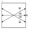
図4および図5はそれぞれ前記第1および第2色相歪曲防止用保護フィルムのTD軸と遅相軸の関係を例示的に示す。図4の第1色相歪曲防止用保護フィルムについて、角度a1(+)はTD軸TD1に対して遅相軸(S1(+))が時計回り方向になす角度を意味し、角度a1(-)はTD軸TD1に対して遅相軸(S1(-))が反時計回り方向になす角度を意味する。図5の第2色相歪曲防止用保護フィルムについて、角度a2(+)はTD軸TD2に対して遅相軸(S2(+))が時計回り方向になす角度を意味して、角度a2(-)はTD軸TD2に対して遅相軸(S2(-))が反時計回り方向になす角度を意味する。FIGS. 4 and 5 illustrate the relationship between the TD axis and the slow axis of the first and second protective films for preventing color distortion, respectively. Regarding thefirst protective film for preventinghuedistortion in FIG.1 (-) means the angle formed by the slow axis (S1 (-)) in the counterclockwise direction with respect to the TD axis TD1 . Regarding thesecondhue distortion preventing protective film ofFIG . a2 (-) means the angle formed by the slow axis (S2 (-)) in the counterclockwise direction with respect to the TD axis TD2 .
一つの例として、前記少なくとも2個の色相歪曲防止用保護フィルムについて、各保護フィルムのTD軸に対して遅相軸がなす角度の絶対値の差は3.5度以下であり得る。 As an example, the difference in the absolute value of the angle formed by the slow axis with respect to the TD axis of each of the at least two protective films for preventing color distortion may be 3.5 degrees or less.
具体的な例として、第1色相歪曲防止用保護フィルムのTD軸に対して遅相軸がなす角度a1と第2色相歪曲防止用保護フィルムのTD軸に対して遅相軸がなす角度a2の絶対値の差(|a1|-|a2|)は3.5度以下であり得る。前記角度の絶対値の差は具体的には、3度以下、2度以下、1度以下、0.5度以下であるか、または前記角度a1およびa2の大きさが互いに同じでもよい。このようなTD軸と遅相軸の関係を通じて、偏光サングラスを着用してディスプレイ装置を観察する時に色相歪曲を効果的に防止することができる。As a specific example, the angle a1 formed by the slow axis with respect to the TD axis of the first protective film for preventing hue distortion and the angle a formed by the slow axis with respect to the TD axis of the second protective film for preventing hue distortion The difference in absolute value of2 (|a1 |−|a2 |) can be 3.5 degrees or less. Specifically, the difference between the absolute values of the angles is 3 degrees or less, 2 degrees or less,1 degree or less, or 0.5 degrees or less, or the angles a1 anda2 may be the same as each other. . Through this relationship between the TD axis and the slow axis, it is possible to effectively prevent color distortion when viewing the display device while wearing polarized sunglasses.
一つの例として、前記少なくとも2個の色相歪曲防止用保護フィルムについて、各保護フィルムのTD軸に対して遅相軸がなす角度はそれぞれ独立的に時計回り方向に0度~4.5度または反時計回り方向に0度~4.5度の範囲内であり得る。 As an example, for the at least two protective films for preventing hue distortion, the angle formed by the slow axis with respect to the TD axis of each protective film is independently 0 degrees to 4.5 degrees in the clockwise direction, or It can be in the range of 0 degrees to 4.5 degrees counterclockwise.
具体的な例として、第1色相歪曲防止用保護フィルムのTD軸に対して遅相軸がなす角度a1と第2色相歪曲防止用保護フィルムのTD軸に対して遅相軸がなす角度a2はそれぞれ独立的に時計回り方向に0度~4.5度、0度~4度、0度~3.5度または0度~3度の範囲内であり得る。 As a specific example, the angle a1 formed by the slow axis with respect to the TD axis of the first protective film for preventing hue distortion and the angle a2 formed by the slow axis with respect to the TD axis of the second protective film for preventing hue distortion are Each independently may be in the range of 0 degrees to 4.5 degrees, 0 degrees to 4 degrees, 0 degrees to 3.5 degrees, or 0 degrees to 3 degrees clockwise.
具体的な例として、第1色相歪曲防止用保護フィルムのTD軸に対して遅相軸がなす角度a1と第2色相歪曲防止用2保護フィルムのTD軸に対して遅相軸がなす角度a2はそれぞれ独立的に反時計回り方向に0度~4.5度、0度~4度、0度~3.5度または0度~3度の範囲内であり得る。As a specific example, the angle a1 formed by the slow axis with respect to the TD axis of thefirst protective film for preventing hue distortion and the angle a1 formed by the slow axis with respect to the TD axis of the second protective film for preventing hue distortion Eacha2 can independently range from 0 degrees to 4.5 degrees, from 0 degrees to 4 degrees, from 0 degrees to 3.5 degrees, or from 0 degrees to 3 degrees in the counterclockwise direction.
具体的な例として、第1色相歪曲防止用保護フィルムのTD軸に対して遅相軸がなす角度a1は時計回り方向に0度~4.5度、0度~4度、0度~3.5度または0度~3度の範囲内であり得、第2色相歪曲防止用保護フィルムのTD軸に対して遅相軸がなす角度a2は反時計回り方向に0度~4.5度、0度~4度、0度~3.5度または0度~3度の範囲内であり得る。As specific examples, the angle a1 formed by the slow axis with respect to the TD axis of thefirst protective film for preventing hue distortion is 0 degrees to 4.5 degrees, 0 degrees to 4 degrees, 0 degrees to The angle a2 formed by the slow axis with respect to the TD axis of thesecond protective film for preventing hue distortion is 0 degree to 4.5 degrees or 0 to 3 degrees in the counterclockwise direction. It can be in the range of 5 degrees, 0 degrees to 4 degrees, 0 degrees to 3.5 degrees or 0 degrees to 3 degrees.
具体的な例として、第1色相歪曲防止用保護フィルムのTD軸に対して遅相軸がなす角度a1は反時計回り方向に0度~4.5度、0度~4度、0度~3.5度または0度~3度の範囲内であり得、第2色相歪曲防止用保護フィルムのTD軸に対して遅相軸がなす角度a2は時計回り方向に0度~4.5度、0度~4度、0度~3.5度または0度~3度の範囲内であり得る。As a specific example, the angle a1 formed by the slow axis with respect to the TD axis of thefirst protective film for preventing hue distortion is 0 degrees to 4.5 degrees, 0 degrees to 4 degrees, and 0 degrees in the counterclockwise direction. The angle a2 formed by the slow axis with respect to the TD axis of thesecond protective film for preventing hue distortion is 0 degree to 4.0 degrees in the clockwise direction. It can be in the range of 5 degrees, 0 degrees to 4 degrees, 0 degrees to 3.5 degrees or 0 degrees to 3 degrees.
一つの例として、前記少なくとも2個の色相歪曲防止用保護フィルムについて、各保護フィルムのTD軸は互いに直交し得る。具体的な例として、第1色相歪曲防止用保護フィルムのTD軸TD1と第2色相歪曲防止用保護フィルムのTD軸TD2は互いに直交し得る。このような配置を通じて、偏光サングラスを着用してディスプレイ装置を観察する時に色相歪曲を効果的に防止することができる。As an example, for the at least two color distortion preventing protective films, the TD axes of each protective film may be orthogonal to each other. As a specific example, the TD axis TD1 of thefirst protective film for preventing color distortion and the TD axis TD2 of thesecond protective film for preventing color distortion may be orthogonal to each other. Through this arrangement, it is possible to effectively prevent color distortion when viewing the display device while wearing polarized sunglasses.
一つの例として、第1保護フィルムと第2保護フィルムのうちいずれか一つの保護フィルムと第3保護フィルムと第4保護フィルムのうちいずれか一つの保護フィルムが、それぞれ前記色相歪曲防止用保護フィルムであり得る。具体的な例として、第1保護フィルムと第4保護フィルムがそれぞれ前記色相歪曲防止用保護フィルムであり得る。このような配置を通じて、偏光サングラスを着用してディスプレイ装置を観察する時に色相歪曲を効果的に防止することができる。 As an example, any one of the first protective film and the second protective film, and any one of the third protective film and the fourth protective film may be the protective film for preventing color distortion. can be As a specific example, each of the first protective film and the fourth protective film may be the protective film for preventing color distortion. Through this arrangement, it is possible to effectively prevent color distortion when viewing the display device while wearing polarized sunglasses.
図6は、偏光サングラスとディスプレイ装置の構造を例示的に示す。図6に示した通り、偏光サングラス40は左眼レンズ401および右眼レンズ402を含むことができ、前記右眼レンズおよび左眼レンズはそれぞれ偏光子を含むことができる。一つの例示において、前記右眼レンズおよび左眼レンズの偏光子の光吸収軸は互いに平行し得る。前記ディスプレイ装置の第1偏光板に含まれる偏光子の光吸収軸と偏光サングラスに含まれる偏光子の光吸収軸は輝度向上の観点で互いに平行し得る。 FIG. 6 exemplarily shows the structure of the polarized sunglasses and the display device. As shown in FIG. 6,
前記第1偏光板は、必要に応じて、視認側に1/4波長板をさらに含むことができる。一つの例示において、1/4波長板の遅相軸と偏光板の光吸収軸は互いに40度~50度、43度~47度、好ましくは45度をなし得る。ディスプレイ装置を偏光サングラスを着用して観察する場合、ディスプレイ装置の偏光板に含まれる偏光子の光吸収軸と偏光サングラスに含まれる偏光子の光吸収軸の関係により、観察者が観察する画面の輝度が低下したり、場合によっては画面が観察されない場合がある。ディスプレイ装置の偏光板が1/4波長板をさらに含む場合、光吸収軸の関係による輝度の低下を防止するという側面で有利であり得る。 The first polarizing plate may further include a quarter-wave plate on the viewing side, if necessary. In one example, the slow axis of the quarter-wave plate and the light absorption axis of the polarizing plate can form 40 to 50 degrees, 43 to 47 degrees, preferably 45 degrees to each other. When the display device is observed by wearing polarized sunglasses, the relationship between the light absorption axis of the polarizer included in the polarizing plate of the display device and the light absorption axis of the polarizer included in the polarized sunglasses affects the size of the screen viewed by the viewer. The brightness may decrease, and the screen may not be observed in some cases. If the polarizing plate of the display device further includes a quarter-wave plate, it may be advantageous in terms of preventing a decrease in brightness due to the relationship of the light absorption axis.
一つの例として、前記ディスプレイパネルは液晶パネルであり得る。液晶パネルは、対向配置された第1基板と第2基板の間に配置された液晶層を含むことができる。前記液晶層は液晶分子を含むことができる。前記液晶分子の種類、物性などは、目的とする液晶パネルの駆動モードにより適切に選択され得る。前記液晶分子としては例えば、ネマチック(nematic)相、スメクチック(smectic)相またはコレステリック(cholesteric)相を示すことができる液晶分子を使うことができる。 As one example, the display panel may be a liquid crystal panel. The liquid crystal panel can include a liquid crystal layer disposed between a first substrate and a second substrate arranged to face each other. The liquid crystal layer may include liquid crystal molecules. The type and physical properties of the liquid crystal molecules can be appropriately selected according to the target driving mode of the liquid crystal panel. The liquid crystal molecules may be, for example, liquid crystal molecules exhibiting a nematic phase, a smectic phase, or a cholesteric phase.
前記液晶パネルの駆動モードとしては、DS(Dynamic Scattering)モード、ECB(Electrically Controllable Birefringence)モード、IPS(In‐Plane Switching)モード、FFS(Fringe‐Field Wwitching)モード、OCB(Optially Compensated Bend)モード、VA(Vertical Alignment)モード、MVA(Multi‐domain Vertical Alignment)モード、PVA(Patterned Vertical Alignment)モード、HAN(Hybrid Aligned Nematic)モード、TN(Twisted Nematic)モードまたはSTN(Super Twisted Nematic)モードなどを例示することができるが、これに制限されるものではない。 Driving modes of the liquid crystal panel include DS (Dynamic Scattering) mode, ECB (Electrically Controllable Birefringence) mode, IPS (In-Plane Switching) mode, FFS (Fringe-Field Switching) mode, OCB (Optically Compensated Bend) mode, Examples include VA (Vertical Alignment) mode, MVA (Multi-domain Vertical Alignment) mode, PVA (Patterned Vertical Alignment) mode, HAN (Hybrid Aligned Nematic) mode, TN (Twisted Nematic) mode, STN (Super Twisted Nematic) mode, etc. can be, but is not limited to.
前記第1基板と第2基板の内側にはそれぞれ第1および第2電極層が形成されていてもよい。前記電極層は液晶層の整列状態を切換できるように、液晶層に電界を印可することができる。前記電極層としては透明電極層を使うことができる。透明電極層としては、例えば、伝導性高分子、伝導性金属、伝導性ナノワイヤーまたはITO(Indium Tin Oxide)等の金属酸化物などを蒸着して形成したものを使うことができる。その他にも透明電極を形成できる多様な素材および形成方法が公知とされており、これを制限なく適用することができる。必要な場合、前記電極層は、適切にパターン化されていてもよい。 First and second electrode layers may be formed inside the first substrate and the second substrate, respectively. The electrode layer can apply an electric field to the liquid crystal layer so as to switch the alignment state of the liquid crystal layer. A transparent electrode layer may be used as the electrode layer. The transparent electrode layer may be formed by depositing a conductive polymer, a conductive metal, a conductive nanowire, or a metal oxide such as ITO (Indium Tin Oxide). In addition, various materials and forming methods capable of forming transparent electrodes are known and can be applied without limitation. If desired, the electrode layer may be appropriately patterned.
前記第1および第2電極層の内側には前記液晶層の配向のための第1および第2配向膜が形成されていてもよい。前記配向膜としては垂直配向膜、水平配向膜、または斜線配向膜を使うことができる。前記配向膜としてはラビング配向膜のように接触式配向膜または光配向膜化合物を含めて、直線偏光の照射などのような非接触式方式によって配向特性を示し得る光配向膜を使うことができる。 First and second alignment films for alignment of the liquid crystal layer may be formed inside the first and second electrode layers. The alignment layer may be a vertical alignment layer, a horizontal alignment layer, or an oblique alignment layer. The alignment layer may be a contact type alignment layer such as a rubbing alignment layer or a photo-alignment layer including a photo-alignment layer compound and a photo-alignment layer capable of exhibiting alignment properties by a non-contact method such as irradiation of linearly polarized light. .
前記第1基板および第2基板としては、例えば、ガラス基板、結晶性または非結晶性シリコンフィルム、石英またはITO(Indium Tin Oxide)フィルムなどの無機系フィルムやプラスチックフィルムなどを使うことができる。前記基板としては、また、光学的に等方性である基材または位相差層のように光学的に異方性である基材を使うことができる。プラスチックフィルム基材の具体的な例として、TAC(triacetyl cellulose);ノルボルネン誘導体などのCOP(cyclo olefin copolymer);PMMA(poly(methyl methacrylate);PC(polycarbonate);PE(polyethylene);PP(polypropylene);PVA(polyvinyl alcohol);DAC(diacetyl cellulose);Pac(Polyacrylate);PES(poly ether sulfone);PEEK(polyetheretherketon);PPS(polyphenylsulfone)、PEI(polyetherimide);PEN(polyethylenemaphthatlate);PET(polyethyleneterephtalate);PI(polyimide);PSF(polysulfone);PAR(polyarylate)または非晶質フッ素樹脂などを含む基材フィルムが例示され得るがこれに制限されるものではない。基材には、必要に応じて金、銀、二酸化ケイ素または一酸化ケイ素などのケイ素化合物のコーティング層や、反射防止層などのコーティング層が存在してもよい。 As the first substrate and the second substrate, for example, a glass substrate, a crystalline or non-crystalline silicon film, an inorganic film such as quartz or an ITO (Indium Tin Oxide) film, or a plastic film can be used. The substrate may also be an optically isotropic substrate or an optically anisotropic substrate such as a retardation layer. Specific examples of plastic film substrates include TAC (triacetyl cellulose); COP (cycloolefin copolymer) such as norbornene derivatives; PMMA (poly (methyl methacrylate); PC (polycarbonate); PE (polyethylene); ;PVA(polyvinyl alcohol);DAC(diacetyl cellulose);Pac(Polyacrylate);PES(poly ether sulfone);PEEK(polyetheretherketon);PPS(polyphenylsulfone)、PEI(polyetherimide);PEN(polyethylenemaphthatlate);PET(polyethyleneterephtalate); PI (polyimide); , silver, silicon compound coating layers such as silicon dioxide or silicon monoxide, and coating layers such as antireflection layers may be present.
前記ディスプレイ装置は液晶パネルの視認側の反対側に光源をさらに含むことができ、前記光源と液晶パネルの間に第2偏光板が配置され得る。前記光源としては通常のバックライトユニットを使用することができ、前記バックライトユニットは発光ランプが配置される方式によりエッジ(edge)方式と直下方式に区別され得る。 The display device may further include a light source opposite the viewing side of the liquid crystal panel, and a second polarizer may be disposed between the light source and the liquid crystal panel. A conventional backlight unit can be used as the light source, and the backlight unit can be classified into an edge type and a direct type depending on how the light emitting lamps are arranged.
前記液晶パネルを含むディスプレイ装置(液晶表示装置)は、例えば、透過型液晶表示装置、半透過型液晶表示装置、反射型液晶表示装置、直視型液晶表示装置または投射型液晶表示装置であり得る。また、液晶表示装置は2次元画像を表示する表示装置であるかまたは3次元画像を表示する立体映像表示装置でもよい。 A display device (liquid crystal display device) including the liquid crystal panel may be, for example, a transmissive liquid crystal display device, a transflective liquid crystal display device, a reflective liquid crystal display device, a direct view liquid crystal display device, or a projection liquid crystal display device. Also, the liquid crystal display device may be a display device that displays a two-dimensional image or a stereoscopic image display device that displays a three-dimensional image.
前記において本出願の偏光板の用途として液晶表示装置を例にして説明したが、本出願の偏光板の用途は前記装置に制限されるものではなく、ディスプレイ装置に偏光板を適用できる多様なディスプレイ装置に適用され得る。他のディスプレイ装置の例としては無機発光表示装置、電界放出表示装置(FED;Field Emission Display)、表面電界放出表示装置(SFED;Surface Field Emission Display)、電子ペーパー(電子インクや電気泳動素子)を利用した表示装置、プラズマ表示装置、投射型表示装置[例えば、回折光バルブ(GLV;grating light valve)表示装置、デジタルマイクロミラーデバイス(Digital Light Processing)を有する表示装置および圧電セラミックス表示装置などがある。また、前記ディスプレイ装置を構成する方式は特に制限されず、本出願の偏光板がディスプレイ装置に含まれる限り、この分野に知られている構成方式に多様に変更され得る。 In the above, the application of the polarizing plate of the present application is described as an example of a liquid crystal display device, but the application of the polarizing plate of the present application is not limited to the above device, and various displays to which the polarizing plate can be applied to the display device. Apparatus can be applied. Examples of other display devices include inorganic light emitting displays, field emission displays (FEDs), surface field emission displays (SFEDs), and electronic paper (electronic ink and electrophoretic elements). Display devices used include plasma display devices, projection display devices [e.g., grating light valve (GLV) display devices, display devices with digital light processing, piezoelectric ceramic display devices, and the like. . In addition, the method of constructing the display device is not particularly limited, and may be variously changed to a method of construction known in the art as long as the polarizing plate of the present application is included in the display device.
本出願は偏光子の保護フィルムにより外部環境、例えば、水分に対する耐久性が優秀であり、偏光サングラスを着用して観察時に色相歪曲を防止できる偏光板および前記偏光板を含むディスプレイ装置を提供することができる。 The present application provides a polarizing plate and a display device including the polarizing plate, which have excellent durability against external environment such as moisture due to the protective film of the polarizer and can prevent color distortion when viewing with polarized sunglasses. can be done.
以下、実施例および比較例を通じて前記の内容をより具体的に説明するが、本出願の範囲は下記に提示された内容によって制限されるものではない。 Hereinafter, the above contents will be described in more detail through examples and comparative examples, but the scope of the present application is not limited by the contents presented below.
実施例1
第1保護フィルムとして、550nm波長の光に対する面内位相差値が315nmであり、TD軸(0度基準)に対して時計回り方向に1度の角度をなす遅相軸を有するPETフィルムを準備した。第2および第3保護フィルムとして、それぞれTD軸に対して遅相軸がなす角度が0度であるTACフィルムを準備した。第4保護フィルムとして、550nm波長の光に対する面内位相差値が315nmであり、TD軸(0度基準)に対して反時計回り方向に1度の角度をなす遅相軸を有するPETフィルムを準備した。第1および第2偏光子として、それぞれ偏光特性が99.995%であるPVA系偏光子を準備した。Example 1
As the first protective film, a PET film having an in-plane retardation value of 315 nm for light with a wavelength of 550 nm and a slow axis forming an angle of 1 degree clockwise with respect to the TD axis (0 degree reference) was prepared. did. As the second and third protective films, TAC films each having an angle of 0 degrees between the slow axis and the TD axis were prepared. As the fourth protective film, a PET film having an in-plane retardation value of 315 nm for light with a wavelength of 550 nm and a slow axis forming an angle of 1 degree counterclockwise with respect to the TD axis (0 degree reference). Got ready. As the first and second polarizers, PVA-based polarizers each having a polarization characteristic of 99.995% were prepared.
第1偏光子の両面に第1および第2保護フィルムをそれぞれ付着して第1偏光板を製造した。また、第2偏光子の両面に第3および第4保護フィルムをそれぞれ付着して第2偏光板を製造した。前記偏光子と保護フィルムの付着はUV硬化方法によって遂行された。この時、第1保護フィルムのTD軸と第1偏光子の光吸収軸が互いに90度をなすように付着し、第4保護フィルムのTD軸と第2偏光子の光吸収軸が互いに90度をなすように付着した。 A first polarizer was manufactured by attaching first and second protective films to both sides of the first polarizer, respectively. Also, the second polarizer was manufactured by attaching the third and fourth protective films to both sides of the second polarizer, respectively. The adhesion of the polarizer and protective film was performed by a UV curing method. At this time, the TD axis of the first protective film and the light absorption axis of the first polarizer are attached at 90 degrees to each other, and the TD axis of the fourth protective film and the light absorption axis of the second polarizer are at 90 degrees to each other. It adhered so as to form a
実施例2
第1保護フィルムの遅相軸がTD軸に対して時計回り方向に3度をなし、第4保護フィルムの遅相軸がTD軸に対して反時計回り方向に3度をなすようにしたことを除いては実施例1と同様にして第1および第2偏光板を製造した。Example 2
The slow axis of the first protective film is 3 degrees clockwise with respect to the TD axis, and the slow axis of the fourth protective film is 3 degrees counterclockwise with respect to the TD axis. First and second polarizing plates were manufactured in the same manner as in Example 1 except for the above.
実施例3
第1保護フィルムの遅相軸がTD軸に対して時計回り方向に3度をなし、第4保護フィルムの遅相軸がTD軸に対して時計回り方向に3度をなすようにしたことを除いては実施例1と同様にして第1および第2偏光板を製造した。Example 3
The slow axis of the first protective film is 3 degrees clockwise with respect to the TD axis, and the slow axis of the fourth protective film is 3 degrees clockwise with respect to the TD axis. First and second polarizing plates were manufactured in the same manner as in Example 1 except for the above.
実施例4
第1保護フィルムの遅相軸がTD軸に対して反時計回り方向に3度をなし、第4保護フィルムの遅相軸がTD軸に対して反時計回り方向に3度をなすようにしたことを除いては実施例1と同様にして第1および第2偏光板を製造した。Example 4
The slow axis of the first protective film is 3 degrees counterclockwise with respect to the TD axis, and the slow axis of the fourth protective film is 3 degrees counterclockwise with respect to the TD axis. First and second polarizing plates were manufactured in the same manner as in Example 1, except for the above.
比較例1
第1保護フィルムの遅相軸がTD軸に対して時計回り方向に4.6度をなし、第4保護フィルムの遅相軸がTD軸に対して反時計回り方向に4.6度をなすようにしたことを除いては実施例1と同様にして第1および第2偏光板を製造した。Comparative example 1
The slow axis of the first protective film forms 4.6 degrees in the clockwise direction with respect to the TD axis, and the slow axis of the fourth protective film forms 4.6 degrees in the counterclockwise direction with respect to the TD axis. First and second polarizing plates were manufactured in the same manner as in Example 1, except that the steps were as follows.
比較例2
第1保護フィルムの遅相軸がTD軸に対して時計回り方向に4.6度をなし、第4保護フィルムの遅相軸がTD軸に対して時計回り方向に4.6度をなすようにしたことを除いては実施例1と同様にして第1および第2偏光板を製造した。Comparative example 2
The slow axis of the first protective film is 4.6 degrees clockwise with respect to the TD axis, and the slow axis of the fourth protective film is 4.6 degrees clockwise with respect to the TD axis. First and second polarizing plates were manufactured in the same manner as in Example 1, except that the
比較例3
第1保護フィルムの遅相軸がTD軸に対して反時計回り方向に4.6度をなし、第4保護フィルムの遅相軸がTD軸に対して反時計回り方向に4.6度をなすようにしたことを除いては実施例1と同様にして第1および第2偏光板を製造した。Comparative example 3
The slow axis of the first protective film is 4.6 degrees counterclockwise with respect to the TD axis, and the slow axis of the fourth protective film is 4.6 degrees counterclockwise with respect to the TD axis. First and second polarizing plates were manufactured in the same manner as in Example 1, except that they were made to do so.
比較例4
第1保護フィルムの遅相軸がTD軸に対して時計回り方向に6度をなし、第4保護フィルムの遅相軸がTD軸に対して反時計回り方向に6度をなすようにしたことを除いては実施例1と同様にして第1および第2偏光板を製造した。Comparative example 4
The slow axis of the first protective film is 6 degrees clockwise with respect to the TD axis, and the slow axis of the fourth protective film is 6 degrees counterclockwise with respect to the TD axis. First and second polarizing plates were manufactured in the same manner as in Example 1 except for the above.
比較例5
第1保護フィルムの遅相軸がTD軸に対して時計回り方向に6度をなし、第4保護フィルムの遅相軸がTD軸に対して時計回り方向に6度をなすようにしたことを除いては実施例1と同様にして第1および第2偏光板を製造した。Comparative example 5
The slow axis of the first protective film is 6 degrees clockwise with respect to the TD axis, and the slow axis of the fourth protective film is 6 degrees clockwise with respect to the TD axis. First and second polarizing plates were manufactured in the same manner as in Example 1 except for the above.
比較例6
第1保護フィルムの遅相軸がTD軸に対して反時計回り方向に6度をなし、第4保護フィルムの遅相軸がTD軸に対して反時計回り方向に6度をなすようにしたことを除いては実施例1と同様にして第1および第2偏光板を製造した。Comparative example 6
The slow axis of the first protective film was 6 degrees counterclockwise with respect to the TD axis, and the slow axis of the fourth protective film was 6 degrees counterclockwise with respect to the TD axis. First and second polarizing plates were manufactured in the same manner as in Example 1, except for the above.
比較例7
第1保護フィルムの遅相軸がTD軸に対して時計回り方向に12度をなし、第4保護フィルムの遅相軸がTD軸に対して反時計回り方向に12度をなすようにしたことを除いては実施例1と同様にして第1および第2偏光板を製造した。Comparative example 7
The slow axis of the first protective film is 12 degrees clockwise with respect to the TD axis, and the slow axis of the fourth protective film is 12 degrees counterclockwise with respect to the TD axis. First and second polarizing plates were manufactured in the same manner as in Example 1 except for the above.
比較例8
第1保護フィルムの遅相軸がTD軸に対して時計回り方向に12度をなし、第4保護フィルムの遅相軸がTD軸に対して時計回り方向に12度をなすようにしたことを除いては実施例1と同様にして第1および第2偏光板を製造した。Comparative example 8
The slow axis of the first protective film is 12 degrees clockwise with respect to the TD axis, and the slow axis of the fourth protective film is 12 degrees clockwise with respect to the TD axis. First and second polarizing plates were manufactured in the same manner as in Example 1 except for the above.
比較例9
第1保護フィルムの遅相軸がTD軸に対して反時計回り方向に12度をなし、第4保護フィルムの遅相軸がTD軸に対して反時計回り方向に12度をなすようにしたことを除いては実施例1と同様にして第1および第2偏光板を製造した。Comparative example 9
The slow axis of the first protective film was 12 degrees counterclockwise with respect to the TD axis, and the slow axis of the fourth protective film was 12 degrees counterclockwise with respect to the TD axis. First and second polarizing plates were manufactured in the same manner as in Example 1, except for the above.
比較例10
第1保護フィルムの遅相軸がTD軸に対して時計回り方向に17度をなし、第4保護フィルムの遅相軸がTD軸に対して反時計回り方向に17度をなすようにしたことを除いては実施例1と同様にして第1および第2偏光板を製造した。Comparative example 10
The slow axis of the first protective film is 17 degrees clockwise with respect to the TD axis, and the slow axis of the fourth protective film is 17 degrees counterclockwise with respect to the TD axis. First and second polarizing plates were manufactured in the same manner as in Example 1 except for the above.
比較例11
第1保護フィルムの遅相軸がTD軸に対して時計回り方向に17度をなし、第4保護フィルムの遅相軸がTD軸に対して時計回り方向に17度をなすようにしたことを除いては実施例1と同様にして第1および第2偏光板を製造した。Comparative example 11
The slow axis of the first protective film is 17 degrees clockwise with respect to the TD axis, and the slow axis of the fourth protective film is 17 degrees clockwise with respect to the TD axis. First and second polarizing plates were manufactured in the same manner as in Example 1 except for the above.
比較例12
第1保護フィルムの遅相軸がTD軸に対して反時計回り方向に17度をなし、第4保護フィルムの遅相軸がTD軸に対して反時計回り方向に17度をなすようにしたことを除いては実施例1と同様にして第1および第2偏光板を製造した。Comparative example 12
The slow axis of the first protective film was 17 degrees counterclockwise with respect to the TD axis, and the slow axis of the fourth protective film was 17 degrees counterclockwise with respect to the TD axis. First and second polarizing plates were manufactured in the same manner as in Example 1, except for the above.
比較例13
第1保護フィルムの遅相軸がTD軸に対して時計回り方向に27度をなし、第4保護フィルムの遅相軸がTD軸に対して反時計回り方向に27度をなすようにしたことを除いては実施例1と同様にして第1および第2偏光板を製造した。Comparative example 13
The slow axis of the first protective film is 27 degrees clockwise with respect to the TD axis, and the slow axis of the fourth protective film is 27 degrees counterclockwise with respect to the TD axis. First and second polarizing plates were manufactured in the same manner as in Example 1 except for the above.
比較例14
第1保護フィルムの遅相軸がTD軸に対して時計回り方向に27度をなし、第4保護フィルムの遅相軸がTD軸に対して時計回り方向に27度をなすようにしたことを除いては実施例1と同様にして第1および第2偏光板を製造した。Comparative example 14
The slow axis of the first protective film is 27 degrees clockwise with respect to the TD axis, and the slow axis of the fourth protective film is 27 degrees clockwise with respect to the TD axis. First and second polarizing plates were manufactured in the same manner as in Example 1 except for the above.
比較例15
第1保護フィルムの遅相軸がTD軸に対して反時計回り方向に27度をなし、第4保護フィルムの遅相軸がTD軸に対して反時計回り方向に27度をなすようにしたことを除いては実施例1と同様にして第1および第2偏光板を製造した。Comparative example 15
The slow axis of the first protective film is 27 degrees counterclockwise with respect to the TD axis, and the slow axis of the fourth protective film is 27 degrees counterclockwise with respect to the TD axis. First and second polarizing plates were manufactured in the same manner as in Example 1, except for the above.
比較例16
第1保護フィルムの遅相軸がTD軸に対して時計回り方向に40.6度をなし、第4保護フィルムの遅相軸がTD軸に対して反時計回り方向に40.6度をなすようにしたことを除いては実施例1と同様にして第1および第2偏光板を製造した。Comparative example 16
The slow axis of the first protective film forms 40.6 degrees clockwise with respect to the TD axis, and the slow axis of the fourth protective film forms 40.6 degrees counterclockwise with respect to the TD axis. First and second polarizing plates were manufactured in the same manner as in Example 1, except that the steps were as follows.
比較例17
第1保護フィルムの遅相軸がTD軸に対して時計回り方向に40.6度をなし、第4保護フィルムの遅相軸がTD軸に対して時計回り方向に40.6度をなすようにしたことを除いては実施例1と同様にして第1および第2偏光板を製造した。Comparative example 17
The slow axis of the first protective film is 40.6 degrees clockwise with respect to the TD axis, and the slow axis of the fourth protective film is 40.6 degrees clockwise with respect to the TD axis. First and second polarizing plates were manufactured in the same manner as in Example 1, except that the
比較例18
第1保護フィルムの遅相軸がTD軸に対して反時計回り方向に40.6度をなし、第4保護フィルムの遅相軸がTD軸に対して反時計回り方向に40.6度をなすようにしたことを除いては実施例1と同様にして第1および第2偏光板を製造した。Comparative Example 18
The slow axis of the first protective film is 40.6 degrees counterclockwise with respect to the TD axis, and the slow axis of the fourth protective film is 40.6 degrees counterclockwise with respect to the TD axis. First and second polarizing plates were manufactured in the same manner as in Example 1, except that they were made to do so.
実施例5~8および比較例19~36
実施例1~4および比較例1~18でそれぞれ、第1保護フィルムと第2保護フィルムの550nm波長の光に対する面内位相差値を720nmに変更したことを除いては、実施例1~4および比較例1~18と同様にして第1および第2偏光板を製造した。Examples 5-8 and Comparative Examples 19-36
In Examples 1 to 4 and Comparative Examples 1 to 18, except that the in-plane retardation value for light with a wavelength of 550 nm of the first protective film and the second protective film was changed to 720 nm. And the first and second polarizing plates were produced in the same manner as in Comparative Examples 1-18.
実施例9~12および比較例37~54
実施例1~4および比較例1~18でそれぞれ、第1保護フィルムと第2保護フィルムの550nm波長の光に対する面内位相差値を954nmに変更したことを除いては、実施例1~4および比較例1~18と同様にして第1および第2偏光板を製造した。Examples 9-12 and Comparative Examples 37-54
In Examples 1 to 4 and Comparative Examples 1 to 18, except that the in-plane retardation value for light with a wavelength of 550 nm of the first protective film and the second protective film was changed to 954 nm. And the first and second polarizing plates were produced in the same manner as in Comparative Examples 1-18.
参考例1
第1、第2、第3および第4保護フィルムについてそれぞれ、TD軸に対して遅相軸がなす角度が0度であるTAC保護フィルムを使ったことを除いては実施例1と同様にして第1および第2偏光板を製造した。Reference example 1
In the same manner as in Example 1, except that the first, second, third, and fourth protective films each used a TAC protective film in which the angle of the slow axis with respect to the TD axis was 0 degrees. First and second polarizers were manufactured.
評価例1.視感評価
実施例1~12、比較例1~54および参考例1で製造された第1偏光板と第2偏光板を、それぞれ液晶表示パネル(AUO社の製品)の両側に付着してディスプレイ装置を準備した。この時、第1保護フィルムのTD軸と第4保護フィルムのTD軸が互いに直交し、また、第2および第3保護フィルムが液晶表示パネル側に近く配置され、第1および第4保護フィルムがディスプレイ装置の外側に配置されるように付着した。Evaluation example 1. Visual Evaluation The first polarizing plates and the second polarizing plates produced in Examples 1 to 12, Comparative Examples 1 to 54, and Reference Example 1 were attached to both sides of a liquid crystal display panel (manufactured by AUO), respectively. Prepared the equipment. At this time, the TD axis of the first protective film and the TD axis of the fourth protective film are orthogonal to each other, the second and third protective films are arranged close to the liquid crystal display panel side, and the first and fourth protective films are It was attached so that it would be placed outside the display device.
偏光サングラスを着用していない状態および偏光サングラス(Luxen社の製品)を着用した状態でそれぞれディスプレイ装置を観察して視感を評価し、その結果を下記の表1~表3に記載した。評価結果は「色相歪曲なし」、「色相歪曲発生」および「色相歪曲強い(虹現象観察)」に区分した。色相歪曲の発生の有無は参考例1の第1偏光板と第2偏光板を前記液晶表示パネルの両側に付着して製造されたディスプレイ装置との色相差で分類した。 Visual perception was evaluated by observing the display device without wearing polarized sunglasses and with polarized sunglasses (product of Luxen), and the results are shown in Tables 1 to 3 below. The evaluation results were classified into "no hue distortion", "occurrence of hue distortion", and "strong hue distortion (observation of rainbow phenomenon)". The presence or absence of color distortion was classified according to the color difference between the display device manufactured by adhering the first polarizing plate and the second polarizing plate of Reference Example 1 to both sides of the liquid crystal display panel.


10:第1偏光板
20:第2偏光板
30:ディスプレイパネル
101:第1偏光子
102:第1保護フィルム
103:第2保護フィルム
201:第2偏光子
202:第3保護フィルム
203:第4保護フィルム
TD、TD1、TD2:TD軸
S(+)、S(-)、S1(+)、S1(-)、S2(+)、S2(-):遅相軸
a(+)、a(-)、a1(+)、a1(-)、a2(+)、a2(-):TD軸に対して遅相軸がなす角度
40:偏光サングラス
401:左眼レンズ
402:右眼レンズ
V:視認軸10: First Polarizing Plate 20: Second Polarizing Plate 30: Display Panel 101: First Polarizer 102: First Protective Film 103: Second Protective Film 201: Second Polarizer 202: Third Protective Film 203: Fourth Protective film TD, TD1 , TD2 : TD axis S (+), S (-), S1 (+), S1 (-), S2 (+), S2 (-): Slow axis a (+), a (-), a1 (+), a1 (-), a2 (+), a2 (-): Angle formed by the slow axis with respect to the TD axis 40: Polarized sunglasses 401: Left eye lens 402: Right eye lens V: Visual axis
Claims (3)
Translated fromJapaneseディスプレイパネル、
前記ディスプレイパネルの視認側に配置され、第1保護フィルム、第1偏光子および第2保護フィルムを順に含む第1偏光板、および
前記ディスプレイパネルの視認側の反対側に配置され、第3保護フィルム、第2偏光子および第4保護フィルムを順に含む第2偏光板を含み、
前記第2および第3保護フィルムが前記ディスプレイパネル側に近く配置され、前記第1および第4保護フィルムが前記ディスプレイ装置の外側に配置され、
前記第1保護フィルムおよび前記第4保護フィルムはそれぞれ、その保護フィルムのTD(Transverse Direction)軸に対して遅相軸(Slow axis)がなす角度が0度~3.0度の範囲内である色相歪曲防止用保護フィルムであり、
前記色相歪曲防止用保護フィルムはポリエチレンテレフタレートフィルムであり、
前記第2保護フィルムおよび前記第3保護フィルムはそれぞれ、TAC(Triacetyl cellulose)フィルムであり、
前記第1保護フィルムのTD軸と前記第4保護フィルムのTD軸は互いに直交しており、
前記第1偏光板は、視認側に1/4波長板をさらに含み、
TD軸は、保護フィルムの幅方向を意味しており、
前記色相歪曲防止用保護フィルムは550nm波長の光に対して下記の数式1で計算される面内位相差値(Rin)が300nm~1000nm範囲内であり、
[数式1]
Rin=(nx-ny)×d
数式1で、nxおよびnyはそれぞれ色相歪曲防止用保護フィルムの550nm波長の光に対するx軸およびy軸方向の屈折率であり、dは色相歪曲防止用保護フィルムの厚さであり、x軸およびy軸はそれぞれ保護フィルムの遅相軸および進相軸を意味する、ディスプレイ装置。A display device,
display panel,
a first polarizing plate disposed on the viewing side of the display panel and comprising in sequence a first protective film, a first polarizer and a second protective film; and a third protective film disposed on the opposite side of the viewing side of the display panel. , a second polarizing plate comprising, in order, a second polarizer and a fourth protective film;
the second and third protective films are arranged near the display panel side, and the first and fourth protective films are arranged outside the display device;
In each of the first protective film and the fourth protective film, the angle formed by the slow axis with respect to the TD (Transverse Direction) axis of the protective film is in the range of 0 degrees to 3.0 degrees. A protective film for preventing color distortion,
The protective film for preventing hue distortion is a polyethylene terephthalate film,
Each of the second protective film and the third protective film is a TAC (Triacetyl cellulose) film,
The TD axis of the first protective film and the TD axis of the fourth protective film areorthogonal to each other,
The first polarizing plate further includes a quarter-wave plate on the viewing side,
TD axis means the width direction of the protective film,
The protective film for preventing hue distortion has an in-plane retardation value (Rin) of 300 nm to 1000 nm calculated by the following formula 1 for light with a wavelength of 550 nm,
[Formula 1]
Rin=(nx−ny)×d
In Equation 1, nx and ny are the refractive indices of the protective film for preventing hue distortion in the x-axis and y-axis directions for light with a wavelength of 550 nm, and d is the thickness of the protective film for preventing hue distortion. A display devicein which the y-axes denote the slow and fast axes of the protective film, respectively .
Priority Applications (1)
| Application Number | Priority Date | Filing Date | Title |
|---|---|---|---|
| JP2022066475AJP2022097515A (en) | 2018-03-28 | 2022-04-13 | Polarizing plate and display device |
Applications Claiming Priority (3)
| Application Number | Priority Date | Filing Date | Title |
|---|---|---|---|
| KR10-2018-0035682 | 2018-03-28 | ||
| KR20180035682 | 2018-03-28 | ||
| PCT/KR2019/003561WO2019190190A1 (en) | 2018-03-28 | 2019-03-27 | Polarizing plate and display device |
Related Child Applications (1)
| Application Number | Title | Priority Date | Filing Date |
|---|---|---|---|
| JP2022066475ADivisionJP2022097515A (en) | 2018-03-28 | 2022-04-13 | Polarizing plate and display device |
Publications (2)
| Publication Number | Publication Date |
|---|---|
| JP2021510424A JP2021510424A (en) | 2021-04-22 |
| JP7125028B2true JP7125028B2 (en) | 2022-08-24 |
Family
ID=68060649
Family Applications (2)
| Application Number | Title | Priority Date | Filing Date |
|---|---|---|---|
| JP2020537683AActiveJP7125028B2 (en) | 2018-03-28 | 2019-03-27 | Polarizer and display device |
| JP2022066475APendingJP2022097515A (en) | 2018-03-28 | 2022-04-13 | Polarizing plate and display device |
Family Applications After (1)
| Application Number | Title | Priority Date | Filing Date |
|---|---|---|---|
| JP2022066475APendingJP2022097515A (en) | 2018-03-28 | 2022-04-13 | Polarizing plate and display device |
Country Status (6)
| Country | Link |
|---|---|
| US (1) | US11415836B2 (en) |
| JP (2) | JP7125028B2 (en) |
| KR (1) | KR102294138B1 (en) |
| CN (1) | CN111656231B (en) |
| TW (1) | TWI784150B (en) |
| WO (1) | WO2019190190A1 (en) |
Families Citing this family (6)
| Publication number | Priority date | Publication date | Assignee | Title |
|---|---|---|---|---|
| KR102621169B1 (en)* | 2019-01-11 | 2024-01-05 | 산진 옵토일렉트로닉스 (난징) 컴퍼니 리미티드 | Preparation Method of Polarizing Plate |
| KR102514152B1 (en) | 2019-11-06 | 2023-03-24 | 삼성에스디아이 주식회사 | Protective film for polarizer, polarizing plate comprising the same and optical display apparatus comprising the same |
| KR102486599B1 (en)* | 2019-12-31 | 2023-01-09 | 삼성에스디아이 주식회사 | Protective film for polarizer, polarizing plate comprising the same and optical display apparatus comprising the same |
| KR20230056218A (en)* | 2021-10-20 | 2023-04-27 | 삼성에스디아이 주식회사 | Polarizing plate and optical display apparatus comprising the same |
| EP4375738A4 (en)* | 2022-01-28 | 2025-01-08 | Samsung Electronics Co., Ltd. | DISPLAY DEVICE |
| JP2024104972A (en)* | 2023-01-25 | 2024-08-06 | シャープディスプレイテクノロジー株式会社 | Liquid crystal panel and display device |
Citations (8)
| Publication number | Priority date | Publication date | Assignee | Title |
|---|---|---|---|---|
| JP2006293331A (en) | 2005-03-11 | 2006-10-26 | Fuji Photo Film Co Ltd | Optical compensation sheet, polarizing plate and liquid crystal display device |
| JP2011053271A (en) | 2009-08-31 | 2011-03-17 | Teijin Dupont Films Japan Ltd | Film for polarizer supporting base material |
| JP2013028755A (en) | 2011-07-29 | 2013-02-07 | Fujifilm Corp | Resin film, method for producing the same, polarizing plate, and liquid crystal display |
| JP2015180912A (en) | 2014-03-05 | 2015-10-15 | 富士フイルム株式会社 | Polarizing plate composition, polarizing plate protective film, and polarizing plate |
| JP2016143046A (en) | 2015-02-05 | 2016-08-08 | コニカミノルタ株式会社 | Lateral electric field mode liquid crystal display device |
| WO2016167221A1 (en) | 2015-04-13 | 2016-10-20 | 富士フイルム株式会社 | Transparent base material film laminate, touch panel sensor film, touch panel, image display device, and method for improving visibility of image display device |
| WO2017170211A1 (en) | 2016-03-31 | 2017-10-05 | 東洋紡株式会社 | Liquid crystal display device |
| WO2018168306A1 (en) | 2017-03-15 | 2018-09-20 | コニカミノルタ株式会社 | Polarizing plate and display device having same |
Family Cites Families (40)
| Publication number | Priority date | Publication date | Assignee | Title |
|---|---|---|---|---|
| JPS6385705A (en)* | 1986-09-30 | 1988-04-16 | Sumitomo Chem Co Ltd | Polarizer |
| KR100757785B1 (en)* | 2001-07-12 | 2007-09-11 | 삼성전자주식회사 | Optical illumination method in liquid crystal display device and liquid crystal display device using same |
| TWI387791B (en)* | 2004-02-26 | 2013-03-01 | Fujifilm Corp | Optical film, optical compensation sheet, polarizing plate, and liquid crystal display device |
| KR20070059096A (en)* | 2004-09-15 | 2007-06-11 | 데이진 가부시키가이샤 | Retardation film |
| JP2008003541A (en)* | 2006-01-27 | 2008-01-10 | Fujifilm Corp | Polarizing plate protective film, polarizing plate and liquid crystal display device using the same |
| JP4307510B1 (en)* | 2007-12-27 | 2009-08-05 | 日東電工株式会社 | Optical display device manufacturing system and method |
| KR20100071255A (en)* | 2008-12-19 | 2010-06-29 | 동우 화인켐 주식회사 | Bottom plate polarizer and in-plane switching mode liquid crystal display comprising the same |
| KR20100106838A (en)* | 2009-03-24 | 2010-10-04 | 동우 화인켐 주식회사 | A laminated polarizer set and in-plane switching mode liquid crystal display comprising the same |
| CN101866030B (en)* | 2009-04-16 | 2014-07-23 | 财团法人工业技术研究院 | Low color shift polarizing element, low color shift polarizing light source and liquid crystal display |
| KR101632611B1 (en)* | 2009-05-04 | 2016-06-22 | 동우 화인켐 주식회사 | A laminated polarizer set and blue phase liquid crystal mode liquid crystal display comprising the same |
| JP5451186B2 (en)* | 2009-06-01 | 2014-03-26 | 帝人デュポンフィルム株式会社 | Uniaxially oriented aromatic polyester film for polarizer support substrate |
| JP5066554B2 (en)* | 2009-07-17 | 2012-11-07 | 株式会社ジャパンディスプレイイースト | Liquid crystal display |
| KR20110014515A (en)* | 2009-08-05 | 2011-02-11 | 제일모직주식회사 | Polarizing plate and liquid crystal display device having same |
| JP5568808B2 (en)* | 2009-10-20 | 2014-08-13 | 住友化学株式会社 | Liquid crystal display device having backlight and optical member set for liquid crystal display device |
| JP5377252B2 (en)* | 2009-11-27 | 2013-12-25 | 日東電工株式会社 | Image display device |
| JP4733227B1 (en)* | 2010-09-30 | 2011-07-27 | 日東電工株式会社 | Liquid crystal display device manufacturing system and manufacturing method |
| JP2013041240A (en)* | 2011-07-20 | 2013-02-28 | Fujifilm Corp | Liquid crystal display device |
| KR101628597B1 (en)* | 2012-06-11 | 2016-06-08 | 후지필름 가부시키가이샤 | Liquid crystal display device |
| TWI609201B (en)* | 2012-08-27 | 2017-12-21 | Lg化學股份有限公司 | Polarizing plate |
| WO2014057949A1 (en) | 2012-10-12 | 2014-04-17 | 富士フイルム株式会社 | Liquid crystal display device |
| KR101768253B1 (en) | 2013-05-30 | 2017-08-14 | 제일모직주식회사 | Polarizing plate, method for preparing the same and liquid crystal display apparatus comprising the same |
| TWI530717B (en)* | 2012-12-17 | 2016-04-21 | 第一毛織股份有限公司 | Polarizing plate, method of preparing the same, and liquid crystal display apparatus including the same |
| CN103048724B (en)* | 2012-12-24 | 2015-06-03 | 明基材料有限公司 | Cutting method and cutting system of polarizing film |
| KR102000145B1 (en)* | 2013-01-04 | 2019-07-16 | 엘지디스플레이 주식회사 | liquid crystal display device with wide-viewing angle |
| CN104919344B (en)* | 2013-03-29 | 2018-01-19 | 大日本印刷株式会社 | Polarizing plate, image display device and method for improving bright contrast of image display device |
| CN105531610B (en)* | 2013-09-10 | 2019-09-03 | 东洋纺株式会社 | Liquid crystal display device, polarizing plate and polarizing plate protective film |
| KR101745755B1 (en) | 2013-09-30 | 2017-06-20 | 주식회사 엘지화학 | Optical element |
| KR20150043641A (en)* | 2013-10-14 | 2015-04-23 | 제일모직주식회사 | Optical film, liquid crystal display including the same and method for preparing protective film applied to the same |
| JP2015111208A (en) | 2013-12-06 | 2015-06-18 | 東洋紡株式会社 | Polarizer protective film, polarizing plate, and liquid crystal display device |
| JP6404036B2 (en)* | 2014-03-05 | 2018-10-10 | 富士フイルム株式会社 | Manufacturing method of polarizing plate |
| KR20160076701A (en)* | 2014-12-23 | 2016-07-01 | 동우 화인켐 주식회사 | Optical film and organic light-emitting display device comprising thereof |
| US11137523B2 (en)* | 2015-11-27 | 2021-10-05 | Skc Co., Ltd. | Polarizer protective film, polarizing plate, and display device comprising same |
| JP6059830B1 (en)* | 2016-01-08 | 2017-01-11 | 大日本印刷株式会社 | Image display device |
| KR20170097921A (en)* | 2016-02-19 | 2017-08-29 | 삼성에스디아이 주식회사 | Polarizer protection film and polarizer plate comprising the same and display device comprising the polarizer plate |
| US10521062B2 (en)* | 2016-04-27 | 2019-12-31 | Zeon Corporation | Film sensor member and method for manufacturing same, circularly polarizing plate and method for manufacturing same, and image display device |
| KR101965477B1 (en)* | 2016-04-28 | 2019-08-07 | 삼성에스디아이 주식회사 | Polarizer plate and curved liquid crystal display including the polarizer plate and method for manufacturing the curved liquid crystal display |
| TWI649591B (en) | 2016-05-31 | 2019-02-01 | 南韓商Skc股份有限公司 | Protective film for polarizing member, polarizing plate including the same, and display device having the same |
| JP6870223B2 (en)* | 2016-06-29 | 2021-05-12 | 日本ゼオン株式会社 | Organic EL display device |
| KR101955763B1 (en)* | 2016-07-29 | 2019-03-07 | 삼성에스디아이 주식회사 | Polarizing plate and optical display apparatus comprising the same |
| CN111869324B (en) | 2018-03-23 | 2024-02-27 | 东洋纺株式会社 | Electroluminescent display device |
- 2019
- 2019-03-27KRKR1020190034743Apatent/KR102294138B1/enactiveActive
- 2019-03-27USUS16/962,191patent/US11415836B2/enactiveActive
- 2019-03-27WOPCT/KR2019/003561patent/WO2019190190A1/ennot_activeCeased
- 2019-03-27TWTW108110762Apatent/TWI784150B/enactive
- 2019-03-27JPJP2020537683Apatent/JP7125028B2/enactiveActive
- 2019-03-27CNCN201980010039.2Apatent/CN111656231B/enactiveActive
- 2022
- 2022-04-13JPJP2022066475Apatent/JP2022097515A/enactivePending
Patent Citations (8)
| Publication number | Priority date | Publication date | Assignee | Title |
|---|---|---|---|---|
| JP2006293331A (en) | 2005-03-11 | 2006-10-26 | Fuji Photo Film Co Ltd | Optical compensation sheet, polarizing plate and liquid crystal display device |
| JP2011053271A (en) | 2009-08-31 | 2011-03-17 | Teijin Dupont Films Japan Ltd | Film for polarizer supporting base material |
| JP2013028755A (en) | 2011-07-29 | 2013-02-07 | Fujifilm Corp | Resin film, method for producing the same, polarizing plate, and liquid crystal display |
| JP2015180912A (en) | 2014-03-05 | 2015-10-15 | 富士フイルム株式会社 | Polarizing plate composition, polarizing plate protective film, and polarizing plate |
| JP2016143046A (en) | 2015-02-05 | 2016-08-08 | コニカミノルタ株式会社 | Lateral electric field mode liquid crystal display device |
| WO2016167221A1 (en) | 2015-04-13 | 2016-10-20 | 富士フイルム株式会社 | Transparent base material film laminate, touch panel sensor film, touch panel, image display device, and method for improving visibility of image display device |
| WO2017170211A1 (en) | 2016-03-31 | 2017-10-05 | 東洋紡株式会社 | Liquid crystal display device |
| WO2018168306A1 (en) | 2017-03-15 | 2018-09-20 | コニカミノルタ株式会社 | Polarizing plate and display device having same |
Also Published As
| Publication number | Publication date |
|---|---|
| KR102294138B1 (en) | 2021-08-27 |
| KR20190113635A (en) | 2019-10-08 |
| US20200341316A1 (en) | 2020-10-29 |
| CN111656231B (en) | 2022-04-19 |
| TW201942609A (en) | 2019-11-01 |
| CN111656231A (en) | 2020-09-11 |
| JP2021510424A (en) | 2021-04-22 |
| JP2022097515A (en) | 2022-06-30 |
| US11415836B2 (en) | 2022-08-16 |
| WO2019190190A1 (en) | 2019-10-03 |
| TWI784150B (en) | 2022-11-21 |
Similar Documents
| Publication | Publication Date | Title |
|---|---|---|
| JP7225508B2 (en) | Optical modulation device | |
| JP7125028B2 (en) | Polarizer and display device | |
| JP7222172B2 (en) | Transparency variable device | |
| TW202020532A (en) | Transmittance -variable device and eyewear comprising the same | |
| JP7225509B2 (en) | Transparency variable device | |
| KR102802177B1 (en) | Transmission Variable Device | |
| JP4935873B2 (en) | OPTICAL LAMINATE, OPTICAL ELEMENT, LIQUID CRYSTAL DISPLAY DEVICE, AND METHOD FOR PRODUCING OPTICAL LAMINATE | |
| JP6146637B2 (en) | Display device | |
| JP2014044258A (en) | Display device |
Legal Events
| Date | Code | Title | Description |
|---|---|---|---|
| A621 | Written request for application examination | Free format text:JAPANESE INTERMEDIATE CODE: A621 Effective date:20200708 | |
| A131 | Notification of reasons for refusal | Free format text:JAPANESE INTERMEDIATE CODE: A131 Effective date:20210823 | |
| A521 | Request for written amendment filed | Free format text:JAPANESE INTERMEDIATE CODE: A523 Effective date:20211122 | |
| A02 | Decision of refusal | Free format text:JAPANESE INTERMEDIATE CODE: A02 Effective date:20211213 | |
| A521 | Request for written amendment filed | Free format text:JAPANESE INTERMEDIATE CODE: A523 Effective date:20220413 | |
| C60 | Trial request (containing other claim documents, opposition documents) | Free format text:JAPANESE INTERMEDIATE CODE: C60 Effective date:20220413 | |
| C11 | Written invitation by the commissioner to file amendments | Free format text:JAPANESE INTERMEDIATE CODE: C11 Effective date:20220425 | |
| A911 | Transfer to examiner for re-examination before appeal (zenchi) | Free format text:JAPANESE INTERMEDIATE CODE: A911 Effective date:20220509 | |
| C21 | Notice of transfer of a case for reconsideration by examiners before appeal proceedings | Free format text:JAPANESE INTERMEDIATE CODE: C21 Effective date:20220516 | |
| TRDD | Decision of grant or rejection written | ||
| A01 | Written decision to grant a patent or to grant a registration (utility model) | Free format text:JAPANESE INTERMEDIATE CODE: A01 Effective date:20220704 | |
| A711 | Notification of change in applicant | Free format text:JAPANESE INTERMEDIATE CODE: A711 Effective date:20220727 | |
| A61 | First payment of annual fees (during grant procedure) | Free format text:JAPANESE INTERMEDIATE CODE: A61 Effective date:20220727 | |
| R150 | Certificate of patent or registration of utility model | Ref document number:7125028 Country of ref document:JP Free format text:JAPANESE INTERMEDIATE CODE: R150 | |
| S111 | Request for change of ownership or part of ownership | Free format text:JAPANESE INTERMEDIATE CODE: R313113 | |
| R350 | Written notification of registration of transfer | Free format text:JAPANESE INTERMEDIATE CODE: R350 | |
| R250 | Receipt of annual fees | Free format text:JAPANESE INTERMEDIATE CODE: R250 |