JP7124727B2 - Exhaust purification device for internal combustion engine and vehicle - Google Patents
Exhaust purification device for internal combustion engine and vehicleDownload PDFInfo
- Publication number
- JP7124727B2 JP7124727B2JP2019009471AJP2019009471AJP7124727B2JP 7124727 B2JP7124727 B2JP 7124727B2JP 2019009471 AJP2019009471 AJP 2019009471AJP 2019009471 AJP2019009471 AJP 2019009471AJP 7124727 B2JP7124727 B2JP 7124727B2
- Authority
- JP
- Japan
- Prior art keywords
- scr catalyst
- amount
- overstorage
- nox
- ammonia storage
- Prior art date
- Legal status (The legal status is an assumption and is not a legal conclusion. Google has not performed a legal analysis and makes no representation as to the accuracy of the status listed.)
- Active
Links
Images


Classifications
- F—MECHANICAL ENGINEERING; LIGHTING; HEATING; WEAPONS; BLASTING
- F01—MACHINES OR ENGINES IN GENERAL; ENGINE PLANTS IN GENERAL; STEAM ENGINES
- F01N—GAS-FLOW SILENCERS OR EXHAUST APPARATUS FOR MACHINES OR ENGINES IN GENERAL; GAS-FLOW SILENCERS OR EXHAUST APPARATUS FOR INTERNAL-COMBUSTION ENGINES
- F01N3/00—Exhaust or silencing apparatus having means for purifying, rendering innocuous, or otherwise treating exhaust
- F01N3/08—Exhaust or silencing apparatus having means for purifying, rendering innocuous, or otherwise treating exhaust for rendering innocuous
- F01N3/10—Exhaust or silencing apparatus having means for purifying, rendering innocuous, or otherwise treating exhaust for rendering innocuous by thermal or catalytic conversion of noxious components of exhaust
- F01N3/18—Exhaust or silencing apparatus having means for purifying, rendering innocuous, or otherwise treating exhaust for rendering innocuous by thermal or catalytic conversion of noxious components of exhaust characterised by methods of operation; Control
- F01N3/20—Exhaust or silencing apparatus having means for purifying, rendering innocuous, or otherwise treating exhaust for rendering innocuous by thermal or catalytic conversion of noxious components of exhaust characterised by methods of operation; Control specially adapted for catalytic conversion
- F01N3/206—Adding periodically or continuously substances to exhaust gases for promoting purification, e.g. catalytic material in liquid form, NOx reducing agents
- F01N3/2066—Selective catalytic reduction [SCR]
- F—MECHANICAL ENGINEERING; LIGHTING; HEATING; WEAPONS; BLASTING
- F01—MACHINES OR ENGINES IN GENERAL; ENGINE PLANTS IN GENERAL; STEAM ENGINES
- F01N—GAS-FLOW SILENCERS OR EXHAUST APPARATUS FOR MACHINES OR ENGINES IN GENERAL; GAS-FLOW SILENCERS OR EXHAUST APPARATUS FOR INTERNAL-COMBUSTION ENGINES
- F01N3/00—Exhaust or silencing apparatus having means for purifying, rendering innocuous, or otherwise treating exhaust
- F01N3/08—Exhaust or silencing apparatus having means for purifying, rendering innocuous, or otherwise treating exhaust for rendering innocuous
- F01N3/10—Exhaust or silencing apparatus having means for purifying, rendering innocuous, or otherwise treating exhaust for rendering innocuous by thermal or catalytic conversion of noxious components of exhaust
- F01N3/18—Exhaust or silencing apparatus having means for purifying, rendering innocuous, or otherwise treating exhaust for rendering innocuous by thermal or catalytic conversion of noxious components of exhaust characterised by methods of operation; Control
- F01N3/20—Exhaust or silencing apparatus having means for purifying, rendering innocuous, or otherwise treating exhaust for rendering innocuous by thermal or catalytic conversion of noxious components of exhaust characterised by methods of operation; Control specially adapted for catalytic conversion
- F01N3/206—Adding periodically or continuously substances to exhaust gases for promoting purification, e.g. catalytic material in liquid form, NOx reducing agents
- F01N3/208—Control of selective catalytic reduction [SCR], e.g. by adjusting the dosing of reducing agent
- B—PERFORMING OPERATIONS; TRANSPORTING
- B01—PHYSICAL OR CHEMICAL PROCESSES OR APPARATUS IN GENERAL
- B01D—SEPARATION
- B01D53/00—Separation of gases or vapours; Recovering vapours of volatile solvents from gases; Chemical or biological purification of waste gases, e.g. engine exhaust gases, smoke, fumes, flue gases, aerosols
- B01D53/34—Chemical or biological purification of waste gases
- B01D53/92—Chemical or biological purification of waste gases of engine exhaust gases
- B01D53/94—Chemical or biological purification of waste gases of engine exhaust gases by catalytic processes
- F—MECHANICAL ENGINEERING; LIGHTING; HEATING; WEAPONS; BLASTING
- F01—MACHINES OR ENGINES IN GENERAL; ENGINE PLANTS IN GENERAL; STEAM ENGINES
- F01N—GAS-FLOW SILENCERS OR EXHAUST APPARATUS FOR MACHINES OR ENGINES IN GENERAL; GAS-FLOW SILENCERS OR EXHAUST APPARATUS FOR INTERNAL-COMBUSTION ENGINES
- F01N11/00—Monitoring or diagnostic devices for exhaust-gas treatment apparatus
- F01N11/002—Monitoring or diagnostic devices for exhaust-gas treatment apparatus the diagnostic devices measuring or estimating temperature or pressure in, or downstream of the exhaust apparatus
- F—MECHANICAL ENGINEERING; LIGHTING; HEATING; WEAPONS; BLASTING
- F01—MACHINES OR ENGINES IN GENERAL; ENGINE PLANTS IN GENERAL; STEAM ENGINES
- F01N—GAS-FLOW SILENCERS OR EXHAUST APPARATUS FOR MACHINES OR ENGINES IN GENERAL; GAS-FLOW SILENCERS OR EXHAUST APPARATUS FOR INTERNAL-COMBUSTION ENGINES
- F01N2250/00—Combinations of different methods of purification
- F01N2250/12—Combinations of different methods of purification absorption or adsorption, and catalytic conversion
- F—MECHANICAL ENGINEERING; LIGHTING; HEATING; WEAPONS; BLASTING
- F01—MACHINES OR ENGINES IN GENERAL; ENGINE PLANTS IN GENERAL; STEAM ENGINES
- F01N—GAS-FLOW SILENCERS OR EXHAUST APPARATUS FOR MACHINES OR ENGINES IN GENERAL; GAS-FLOW SILENCERS OR EXHAUST APPARATUS FOR INTERNAL-COMBUSTION ENGINES
- F01N2550/00—Monitoring or diagnosing the deterioration of exhaust systems
- F01N2550/02—Catalytic activity of catalytic converters
- F—MECHANICAL ENGINEERING; LIGHTING; HEATING; WEAPONS; BLASTING
- F01—MACHINES OR ENGINES IN GENERAL; ENGINE PLANTS IN GENERAL; STEAM ENGINES
- F01N—GAS-FLOW SILENCERS OR EXHAUST APPARATUS FOR MACHINES OR ENGINES IN GENERAL; GAS-FLOW SILENCERS OR EXHAUST APPARATUS FOR INTERNAL-COMBUSTION ENGINES
- F01N2550/00—Monitoring or diagnosing the deterioration of exhaust systems
- F01N2550/20—Monitoring artificially aged exhaust systems
- F—MECHANICAL ENGINEERING; LIGHTING; HEATING; WEAPONS; BLASTING
- F01—MACHINES OR ENGINES IN GENERAL; ENGINE PLANTS IN GENERAL; STEAM ENGINES
- F01N—GAS-FLOW SILENCERS OR EXHAUST APPARATUS FOR MACHINES OR ENGINES IN GENERAL; GAS-FLOW SILENCERS OR EXHAUST APPARATUS FOR INTERNAL-COMBUSTION ENGINES
- F01N2560/00—Exhaust systems with means for detecting or measuring exhaust gas components or characteristics
- F01N2560/02—Exhaust systems with means for detecting or measuring exhaust gas components or characteristics the means being an exhaust gas sensor
- F01N2560/026—Exhaust systems with means for detecting or measuring exhaust gas components or characteristics the means being an exhaust gas sensor for measuring or detecting NOx
- F—MECHANICAL ENGINEERING; LIGHTING; HEATING; WEAPONS; BLASTING
- F01—MACHINES OR ENGINES IN GENERAL; ENGINE PLANTS IN GENERAL; STEAM ENGINES
- F01N—GAS-FLOW SILENCERS OR EXHAUST APPARATUS FOR MACHINES OR ENGINES IN GENERAL; GAS-FLOW SILENCERS OR EXHAUST APPARATUS FOR INTERNAL-COMBUSTION ENGINES
- F01N2560/00—Exhaust systems with means for detecting or measuring exhaust gas components or characteristics
- F01N2560/14—Exhaust systems with means for detecting or measuring exhaust gas components or characteristics having more than one sensor of one kind
- F—MECHANICAL ENGINEERING; LIGHTING; HEATING; WEAPONS; BLASTING
- F01—MACHINES OR ENGINES IN GENERAL; ENGINE PLANTS IN GENERAL; STEAM ENGINES
- F01N—GAS-FLOW SILENCERS OR EXHAUST APPARATUS FOR MACHINES OR ENGINES IN GENERAL; GAS-FLOW SILENCERS OR EXHAUST APPARATUS FOR INTERNAL-COMBUSTION ENGINES
- F01N2570/00—Exhaust treating apparatus eliminating, absorbing or adsorbing specific elements or compounds
- F01N2570/14—Nitrogen oxides
- F—MECHANICAL ENGINEERING; LIGHTING; HEATING; WEAPONS; BLASTING
- F01—MACHINES OR ENGINES IN GENERAL; ENGINE PLANTS IN GENERAL; STEAM ENGINES
- F01N—GAS-FLOW SILENCERS OR EXHAUST APPARATUS FOR MACHINES OR ENGINES IN GENERAL; GAS-FLOW SILENCERS OR EXHAUST APPARATUS FOR INTERNAL-COMBUSTION ENGINES
- F01N2610/00—Adding substances to exhaust gases
- F01N2610/02—Adding substances to exhaust gases the substance being ammonia or urea
- F—MECHANICAL ENGINEERING; LIGHTING; HEATING; WEAPONS; BLASTING
- F01—MACHINES OR ENGINES IN GENERAL; ENGINE PLANTS IN GENERAL; STEAM ENGINES
- F01N—GAS-FLOW SILENCERS OR EXHAUST APPARATUS FOR MACHINES OR ENGINES IN GENERAL; GAS-FLOW SILENCERS OR EXHAUST APPARATUS FOR INTERNAL-COMBUSTION ENGINES
- F01N2610/00—Adding substances to exhaust gases
- F01N2610/14—Arrangements for the supply of substances, e.g. conduits
- F01N2610/1453—Sprayers or atomisers; Arrangement thereof in the exhaust apparatus
- F—MECHANICAL ENGINEERING; LIGHTING; HEATING; WEAPONS; BLASTING
- F01—MACHINES OR ENGINES IN GENERAL; ENGINE PLANTS IN GENERAL; STEAM ENGINES
- F01N—GAS-FLOW SILENCERS OR EXHAUST APPARATUS FOR MACHINES OR ENGINES IN GENERAL; GAS-FLOW SILENCERS OR EXHAUST APPARATUS FOR INTERNAL-COMBUSTION ENGINES
- F01N2900/00—Details of electrical control or of the monitoring of the exhaust gas treating apparatus
- F01N2900/04—Methods of control or diagnosing
- F01N2900/0402—Methods of control or diagnosing using adaptive learning
- F—MECHANICAL ENGINEERING; LIGHTING; HEATING; WEAPONS; BLASTING
- F01—MACHINES OR ENGINES IN GENERAL; ENGINE PLANTS IN GENERAL; STEAM ENGINES
- F01N—GAS-FLOW SILENCERS OR EXHAUST APPARATUS FOR MACHINES OR ENGINES IN GENERAL; GAS-FLOW SILENCERS OR EXHAUST APPARATUS FOR INTERNAL-COMBUSTION ENGINES
- F01N2900/00—Details of electrical control or of the monitoring of the exhaust gas treating apparatus
- F01N2900/04—Methods of control or diagnosing
- F01N2900/0412—Methods of control or diagnosing using pre-calibrated maps, tables or charts
- F—MECHANICAL ENGINEERING; LIGHTING; HEATING; WEAPONS; BLASTING
- F01—MACHINES OR ENGINES IN GENERAL; ENGINE PLANTS IN GENERAL; STEAM ENGINES
- F01N—GAS-FLOW SILENCERS OR EXHAUST APPARATUS FOR MACHINES OR ENGINES IN GENERAL; GAS-FLOW SILENCERS OR EXHAUST APPARATUS FOR INTERNAL-COMBUSTION ENGINES
- F01N2900/00—Details of electrical control or of the monitoring of the exhaust gas treating apparatus
- F01N2900/04—Methods of control or diagnosing
- F01N2900/0416—Methods of control or diagnosing using the state of a sensor, e.g. of an exhaust gas sensor
- F—MECHANICAL ENGINEERING; LIGHTING; HEATING; WEAPONS; BLASTING
- F01—MACHINES OR ENGINES IN GENERAL; ENGINE PLANTS IN GENERAL; STEAM ENGINES
- F01N—GAS-FLOW SILENCERS OR EXHAUST APPARATUS FOR MACHINES OR ENGINES IN GENERAL; GAS-FLOW SILENCERS OR EXHAUST APPARATUS FOR INTERNAL-COMBUSTION ENGINES
- F01N2900/00—Details of electrical control or of the monitoring of the exhaust gas treating apparatus
- F01N2900/06—Parameters used for exhaust control or diagnosing
- F01N2900/14—Parameters used for exhaust control or diagnosing said parameters being related to the exhaust gas
- F01N2900/1402—Exhaust gas composition
- F—MECHANICAL ENGINEERING; LIGHTING; HEATING; WEAPONS; BLASTING
- F01—MACHINES OR ENGINES IN GENERAL; ENGINE PLANTS IN GENERAL; STEAM ENGINES
- F01N—GAS-FLOW SILENCERS OR EXHAUST APPARATUS FOR MACHINES OR ENGINES IN GENERAL; GAS-FLOW SILENCERS OR EXHAUST APPARATUS FOR INTERNAL-COMBUSTION ENGINES
- F01N2900/00—Details of electrical control or of the monitoring of the exhaust gas treating apparatus
- F01N2900/06—Parameters used for exhaust control or diagnosing
- F01N2900/16—Parameters used for exhaust control or diagnosing said parameters being related to the exhaust apparatus, e.g. particulate filter or catalyst
- F01N2900/1602—Temperature of exhaust gas apparatus
- F—MECHANICAL ENGINEERING; LIGHTING; HEATING; WEAPONS; BLASTING
- F01—MACHINES OR ENGINES IN GENERAL; ENGINE PLANTS IN GENERAL; STEAM ENGINES
- F01N—GAS-FLOW SILENCERS OR EXHAUST APPARATUS FOR MACHINES OR ENGINES IN GENERAL; GAS-FLOW SILENCERS OR EXHAUST APPARATUS FOR INTERNAL-COMBUSTION ENGINES
- F01N2900/00—Details of electrical control or of the monitoring of the exhaust gas treating apparatus
- F01N2900/06—Parameters used for exhaust control or diagnosing
- F01N2900/16—Parameters used for exhaust control or diagnosing said parameters being related to the exhaust apparatus, e.g. particulate filter or catalyst
- F01N2900/1622—Catalyst reducing agent absorption capacity or consumption amount
- F—MECHANICAL ENGINEERING; LIGHTING; HEATING; WEAPONS; BLASTING
- F01—MACHINES OR ENGINES IN GENERAL; ENGINE PLANTS IN GENERAL; STEAM ENGINES
- F01N—GAS-FLOW SILENCERS OR EXHAUST APPARATUS FOR MACHINES OR ENGINES IN GENERAL; GAS-FLOW SILENCERS OR EXHAUST APPARATUS FOR INTERNAL-COMBUSTION ENGINES
- F01N2900/00—Details of electrical control or of the monitoring of the exhaust gas treating apparatus
- F01N2900/06—Parameters used for exhaust control or diagnosing
- F01N2900/18—Parameters used for exhaust control or diagnosing said parameters being related to the system for adding a substance into the exhaust
- F01N2900/1806—Properties of reducing agent or dosing system
- F—MECHANICAL ENGINEERING; LIGHTING; HEATING; WEAPONS; BLASTING
- F01—MACHINES OR ENGINES IN GENERAL; ENGINE PLANTS IN GENERAL; STEAM ENGINES
- F01N—GAS-FLOW SILENCERS OR EXHAUST APPARATUS FOR MACHINES OR ENGINES IN GENERAL; GAS-FLOW SILENCERS OR EXHAUST APPARATUS FOR INTERNAL-COMBUSTION ENGINES
- F01N3/00—Exhaust or silencing apparatus having means for purifying, rendering innocuous, or otherwise treating exhaust
- F01N3/02—Exhaust or silencing apparatus having means for purifying, rendering innocuous, or otherwise treating exhaust for cooling, or for removing solid constituents of, exhaust
- F01N3/021—Exhaust or silencing apparatus having means for purifying, rendering innocuous, or otherwise treating exhaust for cooling, or for removing solid constituents of, exhaust by means of filters
- F01N3/023—Exhaust or silencing apparatus having means for purifying, rendering innocuous, or otherwise treating exhaust for cooling, or for removing solid constituents of, exhaust by means of filters using means for regenerating the filters, e.g. by burning trapped particles
- F01N3/029—Exhaust or silencing apparatus having means for purifying, rendering innocuous, or otherwise treating exhaust for cooling, or for removing solid constituents of, exhaust by means of filters using means for regenerating the filters, e.g. by burning trapped particles by adding non-fuel substances to exhaust
- F01N3/0293—Exhaust or silencing apparatus having means for purifying, rendering innocuous, or otherwise treating exhaust for cooling, or for removing solid constituents of, exhaust by means of filters using means for regenerating the filters, e.g. by burning trapped particles by adding non-fuel substances to exhaust injecting substances in exhaust stream
- F—MECHANICAL ENGINEERING; LIGHTING; HEATING; WEAPONS; BLASTING
- F01—MACHINES OR ENGINES IN GENERAL; ENGINE PLANTS IN GENERAL; STEAM ENGINES
- F01N—GAS-FLOW SILENCERS OR EXHAUST APPARATUS FOR MACHINES OR ENGINES IN GENERAL; GAS-FLOW SILENCERS OR EXHAUST APPARATUS FOR INTERNAL-COMBUSTION ENGINES
- F01N3/00—Exhaust or silencing apparatus having means for purifying, rendering innocuous, or otherwise treating exhaust
- F01N3/08—Exhaust or silencing apparatus having means for purifying, rendering innocuous, or otherwise treating exhaust for rendering innocuous
- F01N3/0807—Exhaust or silencing apparatus having means for purifying, rendering innocuous, or otherwise treating exhaust for rendering innocuous by using absorbents or adsorbents
- F01N3/0814—Exhaust or silencing apparatus having means for purifying, rendering innocuous, or otherwise treating exhaust for rendering innocuous by using absorbents or adsorbents combined with catalytic converters, e.g. NOx absorption/storage reduction catalysts
- F—MECHANICAL ENGINEERING; LIGHTING; HEATING; WEAPONS; BLASTING
- F01—MACHINES OR ENGINES IN GENERAL; ENGINE PLANTS IN GENERAL; STEAM ENGINES
- F01N—GAS-FLOW SILENCERS OR EXHAUST APPARATUS FOR MACHINES OR ENGINES IN GENERAL; GAS-FLOW SILENCERS OR EXHAUST APPARATUS FOR INTERNAL-COMBUSTION ENGINES
- F01N3/00—Exhaust or silencing apparatus having means for purifying, rendering innocuous, or otherwise treating exhaust
- F01N3/08—Exhaust or silencing apparatus having means for purifying, rendering innocuous, or otherwise treating exhaust for rendering innocuous
- F01N3/0807—Exhaust or silencing apparatus having means for purifying, rendering innocuous, or otherwise treating exhaust for rendering innocuous by using absorbents or adsorbents
- F01N3/0871—Exhaust or silencing apparatus having means for purifying, rendering innocuous, or otherwise treating exhaust for rendering innocuous by using absorbents or adsorbents using means for controlling, e.g. purging, the absorbents or adsorbents
- F01N3/0885—Regeneration of deteriorated absorbents or adsorbents, e.g. desulfurization of NOx traps
- F—MECHANICAL ENGINEERING; LIGHTING; HEATING; WEAPONS; BLASTING
- F01—MACHINES OR ENGINES IN GENERAL; ENGINE PLANTS IN GENERAL; STEAM ENGINES
- F01N—GAS-FLOW SILENCERS OR EXHAUST APPARATUS FOR MACHINES OR ENGINES IN GENERAL; GAS-FLOW SILENCERS OR EXHAUST APPARATUS FOR INTERNAL-COMBUSTION ENGINES
- F01N3/00—Exhaust or silencing apparatus having means for purifying, rendering innocuous, or otherwise treating exhaust
- F01N3/08—Exhaust or silencing apparatus having means for purifying, rendering innocuous, or otherwise treating exhaust for rendering innocuous
- F01N3/10—Exhaust or silencing apparatus having means for purifying, rendering innocuous, or otherwise treating exhaust for rendering innocuous by thermal or catalytic conversion of noxious components of exhaust
- F01N3/18—Exhaust or silencing apparatus having means for purifying, rendering innocuous, or otherwise treating exhaust for rendering innocuous by thermal or catalytic conversion of noxious components of exhaust characterised by methods of operation; Control
- F01N3/20—Exhaust or silencing apparatus having means for purifying, rendering innocuous, or otherwise treating exhaust for rendering innocuous by thermal or catalytic conversion of noxious components of exhaust characterised by methods of operation; Control specially adapted for catalytic conversion
- F01N3/206—Adding periodically or continuously substances to exhaust gases for promoting purification, e.g. catalytic material in liquid form, NOx reducing agents
- F01N3/2066—Selective catalytic reduction [SCR]
- F01N3/2073—Means for generating a reducing substance from the exhaust gases
- F—MECHANICAL ENGINEERING; LIGHTING; HEATING; WEAPONS; BLASTING
- F01—MACHINES OR ENGINES IN GENERAL; ENGINE PLANTS IN GENERAL; STEAM ENGINES
- F01N—GAS-FLOW SILENCERS OR EXHAUST APPARATUS FOR MACHINES OR ENGINES IN GENERAL; GAS-FLOW SILENCERS OR EXHAUST APPARATUS FOR INTERNAL-COMBUSTION ENGINES
- F01N9/00—Electrical control of exhaust gas treating apparatus
- F01N9/007—Storing data relevant to operation of exhaust systems for later retrieval and analysis, e.g. to research exhaust system malfunctions
- Y—GENERAL TAGGING OF NEW TECHNOLOGICAL DEVELOPMENTS; GENERAL TAGGING OF CROSS-SECTIONAL TECHNOLOGIES SPANNING OVER SEVERAL SECTIONS OF THE IPC; TECHNICAL SUBJECTS COVERED BY FORMER USPC CROSS-REFERENCE ART COLLECTIONS [XRACs] AND DIGESTS
- Y02—TECHNOLOGIES OR APPLICATIONS FOR MITIGATION OR ADAPTATION AGAINST CLIMATE CHANGE
- Y02A—TECHNOLOGIES FOR ADAPTATION TO CLIMATE CHANGE
- Y02A50/00—TECHNOLOGIES FOR ADAPTATION TO CLIMATE CHANGE in human health protection, e.g. against extreme weather
- Y02A50/20—Air quality improvement or preservation, e.g. vehicle emission control or emission reduction by using catalytic converters
- Y—GENERAL TAGGING OF NEW TECHNOLOGICAL DEVELOPMENTS; GENERAL TAGGING OF CROSS-SECTIONAL TECHNOLOGIES SPANNING OVER SEVERAL SECTIONS OF THE IPC; TECHNICAL SUBJECTS COVERED BY FORMER USPC CROSS-REFERENCE ART COLLECTIONS [XRACs] AND DIGESTS
- Y02—TECHNOLOGIES OR APPLICATIONS FOR MITIGATION OR ADAPTATION AGAINST CLIMATE CHANGE
- Y02T—CLIMATE CHANGE MITIGATION TECHNOLOGIES RELATED TO TRANSPORTATION
- Y02T10/00—Road transport of goods or passengers
- Y02T10/10—Internal combustion engine [ICE] based vehicles
- Y02T10/12—Improving ICE efficiencies
- Y—GENERAL TAGGING OF NEW TECHNOLOGICAL DEVELOPMENTS; GENERAL TAGGING OF CROSS-SECTIONAL TECHNOLOGIES SPANNING OVER SEVERAL SECTIONS OF THE IPC; TECHNICAL SUBJECTS COVERED BY FORMER USPC CROSS-REFERENCE ART COLLECTIONS [XRACs] AND DIGESTS
- Y02—TECHNOLOGIES OR APPLICATIONS FOR MITIGATION OR ADAPTATION AGAINST CLIMATE CHANGE
- Y02T—CLIMATE CHANGE MITIGATION TECHNOLOGIES RELATED TO TRANSPORTATION
- Y02T10/00—Road transport of goods or passengers
- Y02T10/10—Internal combustion engine [ICE] based vehicles
- Y02T10/40—Engine management systems
Landscapes
- Engineering & Computer Science (AREA)
- Chemical & Material Sciences (AREA)
- Chemical Kinetics & Catalysis (AREA)
- Combustion & Propulsion (AREA)
- General Engineering & Computer Science (AREA)
- Mechanical Engineering (AREA)
- Health & Medical Sciences (AREA)
- Toxicology (AREA)
- Biomedical Technology (AREA)
- Environmental & Geological Engineering (AREA)
- Analytical Chemistry (AREA)
- General Chemical & Material Sciences (AREA)
- Oil, Petroleum & Natural Gas (AREA)
- Exhaust Gas After Treatment (AREA)
- Exhaust Gas Treatment By Means Of Catalyst (AREA)
Description
Translated fromJapanese本開示は、内燃機関の排気浄化装置、及び車両に関する。 TECHNICAL FIELD The present disclosure relates to an exhaust purification device for an internal combustion engine and a vehicle.
内燃機関の排気浄化装置として、アンモニア(NH3)を還元剤として、排気中のNOxを選択的に還元するNOx選択還元型触媒(Selective Catalytic Reduction:以下、「SCR触媒」と称する)を有するSCR触媒排気浄化システムが知られている(例えば、特許文献1を参照)。 An SCR catalyst having a NOx selective catalytic reduction (hereinafter referred to as an "SCR catalyst") that selectively reduces NOx in exhaust gas using ammonia (NH3) as a reducing agent as an exhaust purification device for an internal combustion engine. Exhaust gas purification systems are known (see, for example, Patent Literature 1).
この種の排気浄化装置において、SCR触媒のNOx還元特性を効果的に機能させるためには、当該SCR触媒中のアンモニアの溜め込み量(以下、「アンモニアストレージ量」と称する)を適切な量にコントロールする必要がある。そのコントロール手法としては、コントロールユニットにて、種々のセンサ情報に基づいて、SCR触媒におけるアンモニアの消費量を逐次的に予測し、不足するアンモニア量を前駆体である尿素水としてSCR触媒に供給する手法が一般的である。 In this type of exhaust purification device, in order to effectively function the NOx reduction characteristics of the SCR catalyst, the amount of ammonia stored in the SCR catalyst (hereinafter referred to as "ammonia storage amount") is controlled to an appropriate amount. There is a need to. As a control method, the control unit sequentially predicts the amount of ammonia consumed by the SCR catalyst based on various sensor information, and supplies the insufficient amount of ammonia to the SCR catalyst as urea water, which is a precursor. method is common.
しかしながら、SCR触媒におけるNOx浄化反応は、複雑であり、そのNOx浄化反応に基づくアンモニアの消費量をコントロールユニットで正確に演算するのは困難である。加えて、アンモニアの消費量の予測値は、尿素水噴射装置における噴射量の誤差やNOxセンサの検出誤差等に起因しても誤差を含むことになる。 However, the NOx purification reaction in the SCR catalyst is complicated, and it is difficult for the control unit to accurately calculate the ammonia consumption based on the NOx purification reaction. In addition, the predicted ammonia consumption amount contains errors due to errors in the injection amount of the urea water injection device, detection errors of the NOx sensor, and the like.
そのため、コントロールユニットの演算により推定されるアンモニアストレージ量の推定値が、実際値と乖離することは稀ではない。そして、その乖離が拡大して、SCR触媒におけるアンモニアストレージ量が過剰な状態(以下、「オーバーストレージ状態」と称する)が発生する場合がある。 Therefore, it is not uncommon for the estimated value of the ammonia storage amount estimated by the calculation of the control unit to deviate from the actual value. Then, the divergence increases, and a state in which the amount of ammonia storage in the SCR catalyst is excessive (hereinafter referred to as an "overstorage state") may occur.
このようなオーバーストレージ状態が発生した場合には、過剰なアンモニアがSCR触媒から脱離し、脱離したアンモニアが後段の酸化触媒によりNOxに変化することで排気浄化装置のNOx浄化性能が低下する。又、脱離したアンモニアが後段の酸化触媒によりアンモニアのまま排出されたとしても、SCR触媒の下流側NOxセンサは、アンモニアをNOxとして検出し、コントローラ側ではNOx浄化性能が低下していると判断してしまうことになる。 When such an overstorage state occurs, excess ammonia is desorbed from the SCR catalyst, and the desorbed ammonia is changed to NOx by the subsequent oxidation catalyst, thereby degrading the NOx purification performance of the exhaust purification device. Even if the desorbed ammonia is discharged as ammonia by the subsequent oxidation catalyst, the downstream NOx sensor of the SCR catalyst detects the ammonia as NOx, and the controller judges that the NOx purification performance is degraded. I will end up doing it.
加えて、オーバーストレージ状態が発生した場合には、余剰な尿素水又はアンモニアが排出されるおそれもある。 In addition, if an overstorage state occurs, there is a possibility that excess urea water or ammonia will be discharged.
本開示は、上記問題点に鑑みてなされたもので、SCR触媒におけるオーバーストレージ状態の発生を早期に検出可能とする内燃機関の排気浄化装置、及び車両を提供することを目的とする。 The present disclosure has been made in view of the above problems, and an object of the present disclosure is to provide an internal combustion engine exhaust gas purification device and a vehicle that enable early detection of the occurrence of an overstorage state in the SCR catalyst.
前述した課題を解決する主たる本開示は、
内燃機関の排気通路に配設される排気浄化装置であって、
前記排気通路内に配設されたSCR(Selective Catalytic Reduction)触媒と、
前記SCR触媒の上流側及び下流側それぞれにおいて排ガス中のNOx量を検出する上流側NOxセンサ及び下流側NOxセンサと、
前記排気通路内の前記SCR触媒の上流側で、尿素水を噴射する尿素水噴射装置と、
前記SCR触媒におけるアンモニアストレージ量を推定し、当該アンモニアストレージ量の推定値に基づいて、前記尿素水噴射装置の尿素水噴射量を制御する制御装置と、
を備え、
前記制御装置は、前記上流側NOxセンサ及び前記下流側NOxセンサそれぞれの検出値の推移をモニタリングし、
前記SCR触媒のNOx浄化率が第1閾値以下まで低下したときに、単位時間あたりの前記上流側NOxセンサの検出値の変化量が第2閾値以上であり、且つ、単位時間あたりの前記下流側NOxセンサの検出値の変化量が第3閾値以下である場合、前記SCR触媒においてオーバーストレージ状態が発生していることを示す異常検出信号を生成する、
排気浄化装置である。The main disclosure that solves the above-mentioned problems is
An exhaust purification device disposed in an exhaust passage of an internal combustion engine,
an SCR (Selective Catalytic Reduction) catalyst disposed in the exhaust passage;
an upstream NOx sensor and a downstream NOx sensor for detecting the amount of NOx in the exhaust gas respectively upstream and downstream of the SCR catalyst;
a urea water injection device for injecting urea water upstream of the SCR catalyst in the exhaust passage;
a control device for estimating an ammonia storage amount in the SCR catalyst and controlling the urea water injection amount of the urea water injection device based on the estimated value of the ammonia storage amount;
with
The control device monitors changes in detection values of the upstream NOx sensor and the downstream NOx sensor,
When the NOx purification rate of the SCR catalyst decreases to a first threshold or less, the amount of change in the detection value of the upstream NOx sensor per unit time is greater than or equal to a second threshold, and the downstream side per unit time generating an abnormality detection signal indicating that an overstorage state has occurred in the SCR catalyst when the amount of change in the detection value of the NOx sensor is equal to or less than a third threshold;
It is an exhaust purification device.
又、他の局面では、
上記排気浄化装置を備える車両である。Also, in other aspects,
A vehicle including the above exhaust purification device.
本開示に係る排気浄化装置によれば、SCR触媒におけるオーバーストレージ状態の発生を早期に検出することができる。 According to the exhaust purification device according to the present disclosure, it is possible to detect the occurrence of an overstorage state in the SCR catalyst at an early stage.
以下に添付図面を参照しながら、本開示の好適な実施形態について詳細に説明する。尚、本明細書及び図面において、実質的に同一の機能を有する構成要素については、同一の符号を付することにより重複説明を省略する。 Preferred embodiments of the present disclosure will be described in detail below with reference to the accompanying drawings. In the present specification and drawings, constituent elements having substantially the same functions are denoted by the same reference numerals, thereby omitting redundant description.
(第1の実施形態)
[排気浄化装置の構成]
以下、図1を参照して、第1の実施形態に係る排気浄化装置の構成について説明する。(First embodiment)
[Configuration of exhaust gas purification device]
The configuration of the exhaust purification system according to the first embodiment will be described below with reference to FIG.
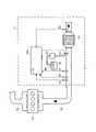
図1は、本実施形態に係る排気浄化装置Uの構成の一例を示す図である。 FIG. 1 is a diagram showing an example of the configuration of an exhaust purification device U according to this embodiment.
本実施形態に係る排気浄化装置Uは、例えば、トラック等の車両に搭載されており、エンジン10の排ガス中のNOxを浄化する。 An exhaust purification device U according to this embodiment is mounted on a vehicle such as a truck, for example, and purifies NOx in the exhaust gas of the
エンジン10は、例えば、燃焼室、燃焼室内で燃料を噴射する燃料噴射装置、及び、燃料噴射装置を制御するエンジンECU等(図示せず)を含んで構成される。エンジン10は、燃焼室内で、燃料と空気の混合気を燃焼及び膨張させて、動力を発生する。エンジン10には、燃焼室内に空気を導入する吸気通路(例えば、吸気管)20と、燃焼室から排出される燃焼後の排ガスを、車両の外部に排出する排気通路(例えば、排気管)30と、が接続されている。 The
尚、本実施形態に係るエンジン10は、4気筒エンジンであり、吸気通路20からは吸気マニホルドを介して四つの燃焼室に分岐し、当該四つの燃焼室から排気マニホルドを介して排気通路30に合流する構成となっている。 Note that the
排気浄化装置Uは、SCR触媒40、尿素水噴射装置50、各種センサ61~64、及び、ECU(Electronic Control Unit)100を備えている。 The exhaust purification device U includes an
SCR触媒40は、尿素水噴射装置50から供給される尿素水が加水分解したアンモニアを吸着すると共に、当該吸着したアンモニアによって排ガス中からNOxを選択的に還元浄化する。SCR触媒40としては、公知のSCR触媒を用いることができ、例えば、セラミック製の担持体の表面に、Feゼオライト、Cuゼオライト又はバナジウム等のNOx還元触媒を担持したものを用いることができる。尚、SCR触媒40としては、触媒上で尿素水をアンモニアに変換するタイプのものを用いてもよい。 The
尿素水噴射装置50は、排気通路30内のSCR触媒40の上流側において、尿素水を噴射する。尿素水噴射装置50は、例えば、尿素水添加弁51、尿素水タンク52、及び、サプライポンプ53を含んで構成される。 The urea
尿素水噴射装置50においては、尿素水タンク52からサプライポンプ53によって圧送された尿素水が、尿素水添加弁51から排気通路30中に噴射される。尿素水添加弁51から排気通路30中に噴射された尿素水は、排ガスの高温により加水分解され、アンモニアに変換されてSCR触媒40に供給される。そして、当該アンモニアは、SCR触媒40に吸着して、当該SCR触媒40の作用でNOxと反応して、NOxを還元浄化する。 In the urea
尿素水噴射装置50から排気通路30に噴射する尿素水の噴射量は、尿素水添加弁51の開度の調整により行われる。尚、尿素水添加弁51の開度の制御は、ECU100(尿素水噴射制御部103)から出力される制御信号によって行われる。 The amount of urea water injected from the urea
各種センサ61~64は、排気通路30を通流する排ガスの状態、及びSCR触媒40の状態等を検出するために設けられている。具体的には、排気通路30には、上流側NOxセンサ61、下流側NOxセンサ62、温度センサ63、及び流量センサ64等が備え付けられている。 Various sensors 61 to 64 are provided to detect the state of the exhaust gas flowing through the
上流側NOxセンサ61は、排気通路30のSCR触媒40の上流側に配設され、SCR触媒40に流入するNOx量(即ち、NOx濃度)を検出する。下流側NOxセンサ62は、排気通路30のSCR触媒40の下流側に配設され、SCR触媒40から流出するNOx量(即ち、NOx濃度)を検出する。温度センサ63は、エンジン10から排出される排ガスの温度を検出する。流量センサ64は、エンジン10から排出される排ガスの流量を検出する。そして、これらの各種センサ61~64は、検出により得られたセンサ情報を、逐次、ECU100に送信する。 The upstream NOx sensor 61 is arranged upstream of the
ECU100(本発明の「制御装置」に相当)は、排気浄化装置Uの動作を制御する。ECU100は、例えば、CPU(Central Processing Unit)、ROM(Read Only Memory)、RAM(Random Access Memory)、入力ポート、及び出力ポート等を含んで構成されている。ECU100の後述する各機能は、例えば、CPUがROM、RAM等に記憶された制御プログラムや各種データを参照することによって実現される。但し、当該機能は、ソフトウェアによる処理に限られず、専用のハードウェア回路によっても実現できることは勿論である。 The ECU 100 (corresponding to the "control device" of the present invention) controls the operation of the exhaust purification device U. The
尚、ECU100は、エンジン10及び尿素水噴射装置50等と通信することで、これらを制御したり、これらの状態情報を取得したりする。又、ECU100は、各種センサ61~64からセンサ情報を取得して、排気通路30を通流する排ガスの状態、及びSCR触媒40の状態等を検出する。 The
[ECU100の詳細構成]
次に、図2~図7を参照して、ECU100の詳細構成の一例について説明する。[Detailed Configuration of ECU 100]
Next, an example of the detailed configuration of the
図2は、本実施形態に係るECU100の構成の一例を示すブロック図である。 FIG. 2 is a block diagram showing an example of the configuration of the
ECU100は、NOx浄化率検出部101、アンモニアストレージ量推定部102、尿素水噴射制御部103、補正係数設定部104、及び、オーバーストレージ状態検出部105を備えている。 The
<NOx浄化率検出部101について>
NOx浄化率検出部101は、SCR触媒40におけるNOx浄化率を検出し、オーバーストレージ状態検出部105に送出する。NOx浄化率検出部101は、例えば、上流側NOxセンサ61のセンサ信号(即ち、SCR触媒40に流入するNOx量)及び下流側NOxセンサ62のセンサ信号(即ち、SCR触媒40から流出するNOx量)に基づいて、SCR触媒40におけるNOx浄化率を検出する。<Regarding NOx
NOx
<アンモニアストレージ量推定部102について>
アンモニアストレージ量推定部102は、SCR触媒40中のアンモニアストレージ量を推定する。アンモニアストレージ量推定部102は、典型的には、尿素水噴射装置50の尿素水噴射量に基づいて、SCR触媒40中に新たに吸着するアンモニアの吸着量を算出し、SCR触媒40に到来するNOx量に基づいて、SCR触媒40中のアンモニアの消費量を算出する。そして、アンモニアストレージ量推定部102は、SCR触媒40に新たに吸着したアンモニアの吸着量から、SCR触媒40中で消費したアンモニアの消費量を減算することによって、現時点におけるSCR触媒40中のアンモニアストレージ量を推定する。つまり、アンモニアストレージ量推定部102は、尿素水噴射量の推移とSCR触媒40におけるアンモニア消費量の推移とに基づいて、記憶部(例えば、RAM)に記憶する現時点のアンモニアストレージ量を逐次的に更新していく。<Regarding Ammonia Storage
Ammonia storage
尚、SCR触媒40中のアンモニアの消費量は、例えば、SCR触媒40に到来するNOx量(例えば、上流側NOxセンサ61のセンサ情報)、排ガス温度(例えば、温度センサ63のセンサ情報)、排ガス流量(例えば、流量センサ64のセンサ情報)、及び、現時点におけるSCR触媒40中のアンモニアストレージ量に基づいて、算出される。 The amount of ammonia consumed in the
アンモニアストレージ量推定部102は、オーバーストレージ状態検出部105から補正指令を受信した場合、記憶部(例えば、RAM)に記憶する現時点におけるSCR触媒40中のアンモニアストレージ量の推定値を、現時点におけるSCR触媒40のストレージ可能量に補正する。これにより、SCR触媒40中のアンモニアストレージ量の推定値が実際値と乖離した場合に、SCR触媒40中のアンモニアストレージ量の推定値を、再度、実際値に近づける(図5を参照して後述)。 When the correction command is received from the overstorage
尚、現時点におけるSCR触媒40のストレージ可能量は、例えば、予め記憶部(例えば、ROM)に記憶した制御マップを用いて、現時点のSCR触媒40(即ち、排ガス温度)から換算される。 Note that the current storage capacity of the
<尿素水噴射制御部103について>
尿素水噴射制御部103は、尿素水添加弁51に開度指令信号を出力することによって、尿素水噴射装置50からの尿素水噴射を制御する。この際、尿素水噴射制御部103は、例えば、アンモニアストレージ量推定部102によって推定されるSCR触媒40におけるアンモニアストレージ量の推定値が目標値に維持されるように、尿素水噴射装置50の尿素水噴射量を制御する。これによって、SCR触媒40を、NOx浄化率が高い状態で維持する。<Regarding the urea water
The urea water
尚、SCR触媒40におけるアンモニアストレージ量の目標値は、現時点における排ガス温度等によって適宜変化させられてもよい。 Note that the target value of the ammonia storage amount in the
尿素水噴射制御部103は、例えば、現時点のSCR触媒40におけるアンモニアストレージ量の推定値と目標値の差分と、尿素水噴射量とを関連付けた制御マップに基づいて、尿素水噴射量を算出する。そして、尿素水噴射制御部103は、制御マップを用いて算出した尿素水噴射量に、補正係数設定部104に設定された尿素噴射補正係数(例えば、0.5~1.5の間のいずれかの値)を乗算した値を、尿素水噴射装置50に指令する尿素水噴射量と決定する。 The urea water
<補正係数設定部104について>
補正係数設定部104は、尿素水噴射制御部103にて尿素水噴射量を決定する際の補正係数である尿素噴射補正係数を設定する。<Regarding Correction
The correction
尿素噴射補正係数は、主に、尿素水噴射装置50の装置誤差(例えば、開度指令信号が指示する弁開度に対する実際の尿素水添加弁51の弁開度の誤差)を校正するべく設定される。つまり、尿素水噴射装置50が実際に噴射する尿素水噴射量は、尿素水噴射装置50の装置誤差に起因して、尿素水噴射制御部103からの指令値からずれる場合があるため、排気浄化装置Uは、尿素噴射補正係数により当該装置誤差を校正する。 The urea injection correction coefficient is mainly set to calibrate the device error of the urea water injection device 50 (for example, the error of the actual valve opening of the urea
尿素噴射補正係数は、例えば、初期状態では「1.0」に設定され、オーバーストレージ状態検出部105からの補正指令に応じて、「0.9」、「0.8」…と段階的に減少させられる。尿素噴射補正係数は、尿素水噴射制御部103からの指令値に係る尿素水噴射量と、実際に尿素水噴射装置50が噴射する尿素水噴射量とを合致させるように機能する。 The urea injection correction coefficient is set to, for example, "1.0" in the initial state, and is gradually changed to "0.9", "0.8", . . . be reduced. The urea injection correction coefficient functions to match the urea water injection amount according to the command value from the urea water
尚、尿素噴射補正係数を適切に設定することは、アンモニアストレージ量推定部102における推定精度の向上にもつながり、アンモニアストレージ量の推定値が実際値と乖離した状態が発生する頻度を低減することにも資する。 Appropriately setting the urea injection correction coefficient also leads to an improvement in the estimation accuracy of the ammonia storage
<オーバーストレージ状態検出部105について>
オーバーストレージ状態検出部105は、SCR触媒40におけるオーバーストレージ状態の発生を検出する。そして、オーバーストレージ状態検出部105は、SCR触媒40におけるオーバーストレージ状態の発生を検出した場合、アンモニアストレージ量推定部102及び補正係数設定部104に対して補正指令(本発明の「異常検出信号」に相当する)を出力する。<Regarding the overstorage
An
オーバーストレージ状態検出部105は、SCR触媒40においてオーバーストレージ状態が発生しているときには、SCR触媒40からアンモニアが継続的にスリップすることから、SCR触媒40の下流で、ある程度のNOx量が継続的に検出され、加えて、SCR触媒40の下流で検出されるNOx量とSCR触媒40の上流で検出されるNOx量との相関が弱くなる、という特性を利用して、SCR触媒40におけるオーバーストレージ状態の発生を検出する。 Overstorage
具体的には、オーバーストレージ状態検出部105は、上流側NOxセンサ61及び下流側NOxセンサ62それぞれの検出値の推移をモニタリングし、SCR触媒40のNOx浄化率が第1閾値以下まで低下したときに、単位時間(例えば、1秒)あたりの上流側NOxセンサ61の検出値の変化量が第2閾値以上であり(以下、「第1条件」と称する)、且つ、単位時間(例えば、1秒)あたりの下流側NOxセンサ62の検出値の変化量が第3閾値以下である(以下、「第2条件」と称する)か否かを判定する。そして、オーバーストレージ状態検出部105は、第1条件及び第2条件の両方が充足している場合、SCR触媒40においてオーバーストレージ状態が発生していると断定する。 Specifically, the overstorage
尚、SCR触媒40のNOx浄化率低下の判定基準である第1閾値としては、例えば、オーバーストレージ状態が発生している場合に通常検出される程度のNOx浄化率が設定され、例えば、70%程度に設定される。 As the first threshold value, which is a criterion for determining a decrease in the NOx purification rate of the
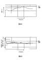
図3は、オーバーストレージ状態とのときにSCR触媒40の下流で検出されるNOx量の挙動(図3A)、及び、その変化量の挙動(図3B)の一例を示す図である。図4は、オーバーストレージ状態とのときにSCR触媒40の上流で検出されるNOx量の挙動(図4A)、及び、その変化量の挙動(図4B)の一例を示す図である。 3A and 3B are diagrams showing an example of the behavior of the amount of NOx detected downstream of the SCR catalyst 40 (FIG. 3A) and the behavior of the amount of change thereof (FIG. 3B) in the overstorage state. FIG. 4 is a diagram showing an example of the behavior of the NOx amount detected upstream of the SCR catalyst 40 (FIG. 4A) and the behavior of the amount of change thereof (FIG. 4B) when in an overstorage state.
オーバーストレージ状態とのときにSCR触媒40の下流で検出されるNOx量は、主に、SCR触媒40でスリップしたアンモニアに起因して検出されたものである(図3を参照)。又、オーバーストレージ状態においては、SCR触媒40におけるNOx浄化率自体は、ある程度高い状態に維持されるため、SCR触媒40の下流で検出されるNOx量には、上流からの排ガス中に含まれるNOxがSCR触媒40で浄化されずに流出したものは、多くは含まれない。 The amount of NOx detected downstream of the
そこで、オーバーストレージ状態検出部105は、単位時間あたりの下流側NOxセンサ62の検出値の変化量が第3閾値以下であるか否か(第2条件)を判定することによって、SCR触媒40からアンモニアが継続的にスリップしている状態を検出する。尚、オーバーストレージ状態検出部105が判定基準とする第3閾値としては、SCR触媒40の下流で検出されるNOx量の変動が小さいことを示す基準値が設定され、例えば、±5ppm/sに設定される。 Therefore, the overstorage
一方、SCR触媒40の上流で検出されるNOx量は、エンジン10から排出される排ガス中に含まれるNOx量であり、エンジン10の運転状態に応じて、大きく変動することになる(図4を参照)。 On the other hand, the amount of NOx detected upstream of the
そこで、オーバーストレージ状態検出部105は、単位時間あたりの上流側NOxセンサ61の検出値の変化量が第2閾値以上であるか否か(第1条件)を判定することによって、SCR触媒40の上流で検出されるNOx量がある程度ダイナミックに変化している状態であることを検出する。即ち、第2条件に加えて、第1条件の充足状態を判定することにより、SCR触媒40に流入するNOx量がある程度ダイナミックに変化している状況下にあって、SCR触媒40の下流で検出されるNOx量が安定していることを確認することが可能である。つまり、第1条件と第2条件の両方を充足しているか否かを判定することによって、SCR触媒40のNOx浄化率が低下している要因が、SCR触媒40におけるアンダーストレージ状態であるのか、又は、SCR触媒40におけるオーバーストレージ状態であるのかを特定することが可能となる。 Therefore, the overstorage
尚、オーバーストレージ状態検出部105が判定基準とする第2閾値としては、上流で検出されるNOx量がある程度ダイナミックに変化していることを示す基準値が設定され、例えば、±50ppm/sに設定される。 As the second threshold used as the determination standard by the overstorage
尚、オーバーストレージ状態検出部105は、状態の継続性を判定するのが望ましい。そのため、オーバーストレージ状態検出部105は、例えば、所定の判定時間(例えば、60秒)内において、単位時間あたりの下流側NOxセンサ62の検出値の変化量が第3閾値(例えば、±50ppm/s)以下である状態が継続していれば、第2条件が充足していると判定するのが望ましい。又、同様に、オーバーストレージ状態検出部105は、例えば、所定の判定時間(例えば、60秒)内において、単位時間あたりの上流側NOxセンサ61の検出値の変化量が第2閾値(例えば、±5ppm/s)以上である状態が所定頻度以上であれば、第1条件が充足していると判定するのが望ましい。 It is desirable that the overstorage
図5は、オーバーストレージ状態検出部105による補正処理を説明する図である。図5の各グラフは、以下の推移を示す。
実線グラフ:SCR触媒40におけるアンモニアストレージ量の推定値の推移
点線グラフ:SCR触媒40におけるアンモニアストレージ量の実際値の推移
一点鎖線グラフ:SCR触媒40におけるストレージ可能量の推移
尚、図5中の矢印T1は、補正処理を行ったタイミングを示す。FIG. 5 is a diagram for explaining correction processing by the overstorage
Solid line graph: change in estimated value of ammonia storage amount in
オーバーストレージ状態検出部105は、SCR触媒40におけるオーバーストレージ状態の発生を検出した場合、アンモニアストレージ量推定部102にアンモニアストレージ量の推定値を補正するように補正指令を行うと共に、補正係数設定部104に尿素噴射補正係数を補正するように補正指令を行う。 When the overstorage
オーバーストレージ状態は、SCR触媒40中のアンモニアが、SCR触媒40のストレージ可能量の限界まで溜め込まれた状態である。従って、オーバーストレージ状態の発生が検出された場合には、アンモニアストレージ量の実際値がストレージ可能量の略100%であるにも関わらず、アンモニアストレージ量の推定値としては、ストレージ可能量に対して80%程度として推定している状態(即ち、アンモニアストレージ量の推定値が実際値から乖離した状態)となっていることを意味する。 The over-storage state is a state in which ammonia in the
そこで、オーバーストレージ状態検出部105は、オーバーストレージ状態が検出された場合には、アンモニアストレージ量の推定値を、その時点におけるSCR触媒40のストレージ可能量に補正するように、補正指令を行う。 Therefore, when the overstorage state is detected, the overstorage
ここで、SCR触媒40のストレージ可能量は、SCR触媒40の温度に応じて変化し、典型的には、SCR触媒40の温度が高くなるにつれて減少する。そのため、アンモニアストレージ量推定部102は、オーバーストレージ状態検出部105から補正指令を受けた場合、例えば、予め記憶した制御マップを用いて、現時点における排ガス温度に基づいて、現時点におけるSCR触媒40のストレージ可能量を算出し、現時点におけるアンモニアストレージ量の推定値を当該ストレージ可能量に補正する。 Here, the storable amount of the
尚、図5では、T1のタイミングで、アンモニアストレージ量推定部102が、SCR触媒40におけるアンモニアストレージ量の推定値を、当該タイミングにおけるSCR触媒40のストレージ可能量に補正した態様を示す。図5では、この補正処理により、T1以降においては、SCR触媒40におけるアンモニアストレージ量の推定値が実際値と一致した状態となっている。 5 shows a mode in which the ammonia storage
又、オーバーストレージ状態検出部105は、オーバーストレージ状態が検出された場合には、尿素噴射補正係数を減少させる方向に補正する。これにより、尿素噴射補正係数がより適切に設定されることになる。換言すると、これにより、アンモニアストレージ量推定部102における推定精度の向上につながり、アンモニアストレージ量の推定値が実際値と乖離した状態が発生する頻度も低減することになる。 Further, when the overstorage state is detected, the overstorage
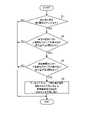
図6は、オーバーストレージ状態検出部105が行う具体的な動作フローの一例を示す図である。図6に示すフローチャートは、例えば、ECU100がコンピュータプログラムに従って、所定間隔(例えば、100ms毎)で実行するものである。 FIG. 6 is a diagram showing an example of a specific operation flow performed by the overstorage
図7は、尿素水噴射装置50における尿素水噴射量の挙動(図7A)、SCR触媒40におけるアンモニアストレージ量の挙動(図7B)、及び、SCR触媒40におけるNOx浄化率の挙動(図7C)の一例を示すタイムチャートである。尚、図7のタイミングT2は、オーバーストレージ状態検出部105が補正指令を行ったタイミングを表している。 7 shows the behavior of the urea water injection amount in the urea water injection device 50 (FIG. 7A), the behavior of the ammonia storage amount in the SCR catalyst 40 (FIG. 7B), and the behavior of the NOx purification rate in the SCR catalyst 40 (FIG. 7C). It is a time chart which shows an example. Note that the timing T2 in FIG. 7 represents the timing when the overstorage
尚、図7Bは、SCR触媒40におけるアンモニアストレージ量の推定値(実線)と実際値(点線)の挙動を示している。又、ここでは、排気浄化装置Uは、SCR触媒40におけるアンモニアストレージ量の推定値が、SCR触媒40のストレージ可能量に対して90%となるように、尿素水噴射量を制御している。 7B shows the behavior of the estimated value (solid line) and actual value (dotted line) of the ammonia storage amount in the
ステップS1において、オーバーストレージ状態検出部105は、SCR触媒40におけるNOx浄化率が第1閾値(例えば、70%)以下まで低下しているか否かを判定する。ここで、SCR触媒40におけるNOx浄化率が第1閾値以下まで低下していない場合(ステップS1:NO)、オーバーストレージ状態検出部105は、特に処理を実行することなく、図6のフローチャートの処理を終了する。一方、SCR触媒40におけるNOx浄化率が第1閾値以下まで低下している場合(ステップS1:YES)、オーバーストレージ状態検出部105は、ステップS2に処理を進める。 In step S1, the overstorage
尚、このステップS1において、オーバーストレージ状態検出部105は、NOx浄化率の積分値に基づいて、SCR触媒40におけるNOx浄化率が低下しているか否かを判定してもよい。これによって、NOx浄化率を検出する際のノイズに起因して、無用に試験動作を実施してしまうことを回避することができる。 In this step S1, the overstorage
ステップS2において、オーバーストレージ状態検出部105は、単位時間あたりの上流側NOxセンサ61の検出値の変化量が第2閾値以上であるか否かを判定する。ここで、上流側NOxセンサ61の検出値の変化量が第2閾値未満である場合(ステップS2:NO)、オーバーストレージ状態検出部105は、特に処理を実行することなく、図6のフローチャートの処理を終了する。一方、上流側NOxセンサ61の検出値の変化量が第2閾値以上である場合(ステップS2:YES)、オーバーストレージ状態検出部105は、ステップS3に処理を進める。 In step S2, the overstorage
ステップS3において、オーバーストレージ状態検出部105は、単位時間あたりの下流側NOxセンサ62の検出値の変化量が第3閾値以下であるか否かを判定する。ここで、下流側NOxセンサ62の検出値の変化量が第3閾値よりも大きい場合(ステップS3:NO)、オーバーストレージ状態検出部105は、特に処理を実行することなく、図6のフローチャートの処理を終了する。一方、下流側NOxセンサ62の検出値の変化量が第3閾値以下である場合(ステップS3:YES)、オーバーストレージ状態検出部105は、ステップS4に処理を進める。 In step S3, the overstorage
ステップS4において、オーバーストレージ状態検出部105は、オーバーストレージ状態が発生していると断定して、アンモニアストレージ量推定部102及び補正係数設定部104に補正指令を送信する。 In step S<b>4 , the overstorage
これにより、アンモニアストレージ量推定部102は、記憶部(例えば、RAM)に記憶する現時点のSCR触媒40のアンモニアストレージ量の推定値を増加させるように補正する。この際、アンモニアストレージ量推定部102は、例えば、記憶部(例えば、RAM)に記憶する現時点のSCR触媒40のアンモニアストレージ量の推定値を、現時点のSCR触媒40のストレージ可能量に補正する。 Accordingly, the ammonia storage
尚、このステップS4において、アンモニアストレージ量推定部102がアンモニアストレージ量の推定値を増加させる処理は、任意の手法であってよい。かかる処理は、例えば、段階的に(例えば、5%毎)、アンモニアストレージ量の推定値を増加させる処理であってもよい。かかる手法であっても、図6のフローチャートの処理を繰り返し実行することで、アンモニアストレージ量の推定値を段階的に実際値に近づけることができる。 In this step S4, the process of causing the ammonia storage
又、オーバーストレージ状態検出部105から補正指令を受けた補正係数設定部104は、記憶部(例えば、RAM)に記憶する現時点の尿素噴射補正係数を減少させるように補正する。この際、補正係数設定部104は、例えば、記憶部(例えば、RAM)に記憶する現時点の尿素噴射補正係数を、1段階減少させる方向に補正する。 Further, the correction
このステップS4によって、尿素水噴射装置50から噴射される尿素水噴射量は、オーバーストレージ状態検出前よりも減少することになり、SCR触媒40におけるNOx浄化率は、時間の経過と共に回復することになる(図7を参照)。 By this step S4, the urea water injection amount injected from the urea
又、このステップS4で、尿素噴射補正係数を減少させることによって、アンモニアストレージ量の推定値と目標値との間の差分の単位量当たりの尿素水噴射量を減少させることになるため、尿素水噴射装置50の装置誤差に伴う過剰噴射を抑制することができる。 Further, in step S4, by decreasing the urea injection correction coefficient, the urea water injection amount per unit amount of the difference between the estimated ammonia storage amount and the target value is decreased. Excessive injection due to device error of the
尚、ステップS4を実行した際には、所定時間(例えば、10分間)、図6に示すフローチャートの処理の実行を禁止するのが望ましい。これによって、SCR触媒40におけるNOx浄化率が回復する前に、SCR触媒40のアンモニアストレージ量の推定値及び尿素噴射補正係数を補正する処理を繰り返し実行してしまうことを抑制することができる。 Incidentally, when step S4 is executed, it is desirable to prohibit execution of the processing of the flowchart shown in FIG. 6 for a predetermined time (for example, 10 minutes). As a result, it is possible to prevent repeated execution of the process of correcting the estimated value of the ammonia storage amount of the
以上のような処理により、SCR触媒40のアンモニアストレージ量の推定値と実際値との間の乖離は、解消されることになる。又、尿素噴射補正係数も適切な値に設定されることになるため、長期的に見て、SCR触媒40のアンモニアストレージ量の推定値と実際値との間の乖離が発生する頻度も抑制されることになる。 Through the above processing, the deviation between the estimated value and the actual value of the ammonia storage amount of the
[効果]
以上のように、本実施形態に係る排気浄化装置Uによれば、早期に、SCR触媒におけるオーバーストレージ状態の発生を検出することができる。又、本実施形態に係る排気浄化装置Uによれば、高精度に、SCR触媒におけるオーバーストレージ状態の発生を検出することができる。そして、これにより、アンモニアストレージ量の推定値、及び、尿素噴射補正係数を適切に補正することができる。[effect]
As described above, according to the exhaust purification device U according to the present embodiment, it is possible to detect the occurrence of the overstorage state in the SCR catalyst at an early stage. Further, according to the exhaust purification device U according to the present embodiment, it is possible to detect the occurrence of the overstorage state in the SCR catalyst with high accuracy. Accordingly, the estimated value of the ammonia storage amount and the urea injection correction coefficient can be appropriately corrected.
(第2の実施形態)
次に、図8、図9を参照して、第2の実施形態に係るECU100の構成について説明する。本実施形態に係るECU100は、オーバーストレージ状態検出部105における判定条件の点で、第1の実施形態と相違する。尚、第1の実施形態と共通する構成については、説明を省略する。(Second embodiment)
Next, the configuration of the
本実施形態に係るオーバーストレージ状態検出部105は、オーバーストレージ状態の誤検出を抑制する観点から、上記した第1条件及び第2条件に加えて、第3条件及び第4条件を、オーバーストレージ状態が発生しているか否かを判定するための判定条件とする。 From the viewpoint of suppressing erroneous detection of the overstorage state, the overstorage
図8は、SCR触媒40の温度の挙動(図8A)、及び、その変化量の挙動(図8B)の一例を示す図である。 FIG. 8 is a diagram showing an example of behavior of the temperature of the SCR catalyst 40 (FIG. 8A) and behavior of the amount of change thereof (FIG. 8B).
図9は、本実施形態に係るオーバーストレージ状態検出部105が行う具体的な動作フローの一例を示す図である。 FIG. 9 is a diagram showing an example of a specific operation flow performed by the overstorage
尚、図9のフローチャートは、図6のフローチャートのステップS3の後に、上記第3条件に対応するステップSaの判定処理、及び、上記第4条件に対応するステップSbの判定処理が追加されている点で、図6のフローチャートと相違する。 In the flowchart of FIG. 9, after step S3 of the flowchart of FIG. 6, determination processing of step Sa corresponding to the third condition and determination processing of step Sb corresponding to the fourth condition are added. 6 differs from the flowchart in FIG.
まず、オーバーストレージ状態検出部105は、第3条件として、SCR触媒40の温度が第4閾値以下であり、且つ、SCR触媒40の温度の変化量が第5閾値以下であるか否かを判定する(ステップSa)。そして、オーバーストレージ状態検出部105は、SCR触媒40の温度が第4閾値以下であり、且つ、SCR触媒40の温度の変化量が第5閾値以下である場合(ステップSa:YES)、SCR触媒40においてオーバーストレージ状態が発生しているおそれがあると断定する。一方、オーバーストレージ状態検出部105は、当該第3条件を充足しない場合(ステップSa:NO)、適切な判定タイミングではないと判断して、図9のフローチャートの処理を終了する。 First, as the third condition, the overstorage
一般に、SCR触媒40の温度は、排ガス温度に依拠するため、エンジン10の運転状態に応じて、時間的に変動する(図8を参照)。そして、SCR触媒40の温度が高い場合には、SCR触媒40においてオーバーストレージ状態が発生しているか否かに関わらず、SCR触媒40からアンモニアスリップが発生することになる。特に、SCR触媒40の温度が急上昇している際には、SCR触媒40からのアンモニアスリップの量も大きくなる。 In general, the temperature of the
オーバーストレージ状態検出部105は、かかる高温時のアンモニアスリップに起因して、SCR触媒40においてオーバーストレージ状態が発生していると誤検出する状態を回避するため、上記第3条件を更なる判定条件とする。尚、オーバーストレージ状態検出部105が判定基準とするSCR触媒40の温度に係る第4閾値としては、例えば、350℃が設定され、SCR触媒40の温度変化に係る第5閾値としては、例えば、5℃/sが設定される。 In order to avoid a state in which the
又、オーバーストレージ状態検出部105は、第4条件として、SCR触媒40におけるストレージ可能量とアンモニアストレージ量の推定値との差が第6閾値以下であるか否かを判定する(ステップSb)。そして、オーバーストレージ状態検出部105は、SCR触媒40におけるストレージ可能量とアンモニアストレージ量の推定値との差が第6閾値以下である場合(ステップSb:YES)、SCR触媒40においてオーバーストレージ状態が発生しているおそれがあると断定する。一方、オーバーストレージ状態検出部105は、当該第4条件を充足しない場合(ステップSb:NO)、適切な判定タイミングではないと判断して、図9のフローチャートの処理を終了する。 As a fourth condition, the overstorage
一般に、SCR触媒40のストレージ可能量は、SCR触媒40の温度に依拠するため、エンジン10の運転状態に応じて、時間的に変動する(図5の一点鎖線グラフを参照)。そして、SCR触媒40の温度が急上昇した際等において、SCR触媒40のストレージ可能量が低下したときには、SCR触媒40からのアンモニアスリップが発生することになる。つまり、アンモニアストレージ量の推定値が、SCR触媒40のストレージ可能量付近である場合には、アンモニアストレージ量の推定値が実際値と乖離していないにも関わらず、オーバーストレージ状態検出部105は、アンモニアストレージ量の推定値が実際値と乖離していると判断してしまうおそれがある。 In general, the storable amount of the
オーバーストレージ状態検出部105は、このような誤判断を回避するため、上記第4条件を更なる判定条件とする。尚、この場合には、SCR触媒40に一時的にオーバーストレージ状態が発生していると言えるが、アンモニアストレージ量の推定値が実際値と乖離している訳ではないため、補正処理を実行する自体を回避する観点から、本実施形態に係るオーバーストレージ状態検出部105は、上記第4条件を更なる判定条件として設定する。 In order to avoid such an erroneous determination, the overstorage
オーバーストレージ状態検出部105が判定基準とするストレージ可能量とアンモニアストレージ量の推定値との差に係る第6閾値としては、例えば、5%程度が設定される。 For example, about 5% is set as the sixth threshold for the difference between the storage capacity and the estimated value of the ammonia storage amount, which is used as a criterion by the overstorage
以上のように、本実施形態に係るECU100によれば、より高精度に、SCR触媒40におけるオーバーストレージ状態、即ち、アンモニアストレージ量の推定値が実際値と乖離している状態を検出することができる。 As described above, according to the
(その他の実施形態)
本発明は、上記実施形態に限らず、種々に変形態様が考えられる。(Other embodiments)
The present invention is not limited to the above-described embodiment, and various modifications are conceivable.
上記実施形態では、ECU100の構成の一例として、NOx浄化率検出部101、アンモニアストレージ量推定部102、尿素水噴射制御部103、補正係数設定部104、及び、オーバーストレージ状態検出部105の機能が一のコンピュータによって実現されるものとして記載したが、複数のコンピュータによって実現されてもよいのは勿論である。例えば、アンモニアストレージ量推定部102の機能と尿素水噴射制御部103の機能は、それぞれ別個のECUに搭載されてもよい。 In the above embodiment, as an example of the configuration of the
又、上記実施形態では、一例として、排気浄化装置Uをディーゼルエンジンに適用した態様ついて説明する。但し、本実施形態に係る排気浄化装置Uは、ディーゼルエンジンに限らず、ガソリンエンジンにも適用し得る。 Moreover, in the above-described embodiment, as an example, a mode in which the exhaust purification device U is applied to a diesel engine will be described. However, the exhaust purification device U according to this embodiment is applicable not only to diesel engines but also to gasoline engines.
又、上記実施形態では、排気浄化装置Uの適用対象の一例として、車両を示したが、排気浄化装置Uの適用対象は、これに限定されない。例えば、排気浄化装置Uは、発電機、建設機械、船舶等に適用されてもよい。 Further, in the above embodiment, a vehicle is shown as an example of an application target of the exhaust purification device U, but the application target of the exhaust purification device U is not limited to this. For example, the exhaust purification device U may be applied to generators, construction machinery, ships, and the like.
以上、本発明の具体例を詳細に説明したが、これらは例示にすぎず、請求の範囲を限定するものではない。請求の範囲に記載の技術には、以上に例示した具体例を様々に変形、変更したものが含まれる。 Although specific examples of the present invention have been described in detail above, these are merely examples and do not limit the scope of the claims. The technology described in the claims includes various modifications and changes of the specific examples illustrated above.
本開示に係る排気浄化装置によれば、SCR触媒におけるオーバーストレージ状態の発生を早期に検出することができる。 According to the exhaust purification device according to the present disclosure, it is possible to detect the occurrence of an overstorage state in the SCR catalyst at an early stage.
U 排気浄化装置
10 エンジン
20 吸気通路
30 排気通路
40 SCR触媒(NOx選択還元化型触媒)
50 尿素水噴射装置
51 尿素水添加弁
52 尿素水タンク
53 サプライポンプ
61 上流側NOxセンサ
62 下流側NOxセンサ
63 温度センサ
64 流量センサ
100 ECU(制御装置)
101 NOx浄化率検出部
102 アンモニアストレージ量推定部
103 尿素水噴射制御部
104 補正係数設定部
105 オーバーストレージ状態検出部U
50 Aqueous
101 NOx purification
Claims (6)
Translated fromJapanese前記排気通路内に配設されたSCR(Selective Catalytic Reduction)触媒と、
前記SCR触媒の上流側及び下流側それぞれにおいて排ガス中のNOx量を検出する上流側NOxセンサ及び下流側NOxセンサと、
前記排気通路内の前記SCR触媒の上流側で、尿素水を噴射する尿素水噴射装置と、
前記SCR触媒におけるアンモニアストレージ量を推定し、当該アンモニアストレージ量の推定値に基づいて、前記尿素水噴射装置の尿素水噴射量を制御する制御装置と、
を備え、
前記制御装置は、前記上流側NOxセンサ及び前記下流側NOxセンサそれぞれの検出値の推移をモニタリングし、
前記SCR触媒のNOx浄化率が第1閾値以下まで低下したときに、単位時間あたりの前記上流側NOxセンサの検出値の変化量が第2閾値以上であり、且つ、単位時間あたりの前記下流側NOxセンサの検出値の変化量が第3閾値以下である場合、前記SCR触媒においてオーバーストレージ状態が発生していることを示す異常検出信号を生成する、
排気浄化装置。An exhaust purification device disposed in an exhaust passage of an internal combustion engine,
an SCR (Selective Catalytic Reduction) catalyst disposed in the exhaust passage;
an upstream NOx sensor and a downstream NOx sensor for detecting the amount of NOx in the exhaust gas respectively upstream and downstream of the SCR catalyst;
a urea water injection device for injecting urea water upstream of the SCR catalyst in the exhaust passage;
a control device for estimating an ammonia storage amount in the SCR catalyst and controlling the urea water injection amount of the urea water injection device based on the estimated value of the ammonia storage amount;
with
The control device monitors changes in detection values of the upstream NOx sensor and the downstream NOx sensor,
When the NOx purification rate of the SCR catalyst decreases to a first threshold or less, the amount of change in the detection value of the upstream NOx sensor per unit time is greater than or equal to a second threshold, and the downstream side per unit time generating an abnormality detection signal indicating that an overstorage state has occurred in the SCR catalyst when the amount of change in the detection value of the NOx sensor is equal to or less than a third threshold;
Exhaust purification device.
請求項1に記載の排気浄化装置。The control device generates the abnormality detection signal only when the temperature of the SCR catalyst is equal to or lower than a fourth threshold and the amount of change in the temperature of the SCR catalyst is equal to or lower than a fifth threshold.
The exhaust purification device according to claim 1.
請求項1又は2に記載の排気浄化装置。The control device generates the abnormality detection signal only when a difference between a possible ammonia storage amount in the SCR catalyst and an estimated value of the ammonia storage amount is equal to or greater than a sixth threshold.
The exhaust purification device according to claim 1 or 2.
請求項1乃至3のいずれか一項に記載の排気浄化装置。When the abnormality detection signal is generated, the control device corrects the estimated value of the ammonia storage amount to the current storage capacity of the SCR catalyst.
The exhaust purification device according to any one of claims 1 to 3.
請求項1乃至4のいずれか一項に記載の排気浄化装置。When the abnormality detection signal is generated, the controller controls the injection amount of the aqueous urea solution so that the injection amount of the aqueous urea solution per unit amount of the difference between the estimated ammonia storage amount and the target value is decreased. to correct the correction factor that adjusts the
The exhaust purification device according to any one of claims 1 to 4.
Priority Applications (5)
| Application Number | Priority Date | Filing Date | Title |
|---|---|---|---|
| JP2019009471AJP7124727B2 (en) | 2019-01-23 | 2019-01-23 | Exhaust purification device for internal combustion engine and vehicle |
| CN202080009899.7ACN113316679B (en) | 2019-01-23 | 2020-01-20 | Exhaust gas purifying device for internal combustion engine and vehicle |
| PCT/JP2020/001723WO2020153302A1 (en) | 2019-01-23 | 2020-01-20 | Exhaust gas purification device for internal combustion engine, and vehicle |
| US17/424,759US11761364B2 (en) | 2019-01-23 | 2020-01-20 | Exhaust gas purification device for internal combustion engine, and vehicle |
| DE112020000496.1TDE112020000496T5 (en) | 2019-01-23 | 2020-01-20 | Exhaust gas purification device for internal combustion engine and vehicle |
Applications Claiming Priority (1)
| Application Number | Priority Date | Filing Date | Title |
|---|---|---|---|
| JP2019009471AJP7124727B2 (en) | 2019-01-23 | 2019-01-23 | Exhaust purification device for internal combustion engine and vehicle |
Publications (2)
| Publication Number | Publication Date |
|---|---|
| JP2020118078A JP2020118078A (en) | 2020-08-06 |
| JP7124727B2true JP7124727B2 (en) | 2022-08-24 |
Family
ID=71736153
Family Applications (1)
| Application Number | Title | Priority Date | Filing Date |
|---|---|---|---|
| JP2019009471AActiveJP7124727B2 (en) | 2019-01-23 | 2019-01-23 | Exhaust purification device for internal combustion engine and vehicle |
Country Status (5)
| Country | Link |
|---|---|
| US (1) | US11761364B2 (en) |
| JP (1) | JP7124727B2 (en) |
| CN (1) | CN113316679B (en) |
| DE (1) | DE112020000496T5 (en) |
| WO (1) | WO2020153302A1 (en) |
Families Citing this family (2)
| Publication number | Priority date | Publication date | Assignee | Title |
|---|---|---|---|---|
| CN113279849B (en)* | 2021-07-05 | 2023-04-07 | 凯龙高科技股份有限公司 | NH3 leakage identification and detection method for SCR system |
| US11879375B2 (en)* | 2022-06-01 | 2024-01-23 | Paccar Inc | Exhaust after-treatment in heavy-duty motor vehicles |
Citations (7)
| Publication number | Priority date | Publication date | Assignee | Title |
|---|---|---|---|---|
| JP2003293743A (en) | 2002-04-03 | 2003-10-15 | Mitsubishi Fuso Truck & Bus Corp | NOx CLEANING DEVICE FOR INTERNAL COMBUSTION ENGINE |
| JP2010038022A (en) | 2008-08-04 | 2010-02-18 | Toyota Motor Corp | Exhaust emission control device of internal-combustion engine |
| JP2010077812A (en) | 2008-09-24 | 2010-04-08 | Mazda Motor Corp | Exhaust emission control device for engine |
| JP2010248963A (en) | 2009-04-14 | 2010-11-04 | Nippon Soken Inc | Exhaust emission control device for internal combustion engine |
| JP2010261388A (en) | 2009-05-08 | 2010-11-18 | Toyota Motor Corp | Exhaust gas purification device for internal combustion engine |
| JP2011094540A (en) | 2009-10-30 | 2011-05-12 | Toyota Industries Corp | Exhaust gas purification apparatus in internal combustion engine |
| US20190010851A1 (en) | 2017-07-07 | 2019-01-10 | GM Global Technology Operations LLC | Selective catalytic reduction steady state ammonia slip and reductant breakthrough detection |
Family Cites Families (14)
| Publication number | Priority date | Publication date | Assignee | Title |
|---|---|---|---|---|
| US7858060B2 (en)* | 2008-07-30 | 2010-12-28 | Gm Global Technology Operations, Inc | Current storage estimation for selective catalytic reduction catalysts |
| US8844268B2 (en)* | 2009-01-19 | 2014-09-30 | Toyota Jidosha Kabushiki Kaisha | Abnormality detection apparatus for exhaust gas purification apparatus and abnormality detection method for exhaust gas purification apparatus |
| WO2011065243A1 (en) | 2009-11-28 | 2011-06-03 | Semiconductor Energy Laboratory Co., Ltd. | Semiconductor device and manufacturing method thereof |
| JP5837312B2 (en) | 2011-03-10 | 2015-12-24 | 本田技研工業株式会社 | Exhaust gas purification system for internal combustion engine |
| EP2831387B1 (en) | 2012-03-29 | 2019-09-04 | Volvo Construction Equipment AB | Method for diagnosing a selective catalytic reduction catalyst |
| EP3051087B1 (en) | 2013-09-25 | 2017-10-25 | Toyota Jidosha Kabushiki Kaisha | Abnormality diagnosis apparatus for exhaust gas purification apparatus |
| JP6248789B2 (en) | 2014-05-08 | 2017-12-20 | いすゞ自動車株式会社 | Exhaust purification system |
| WO2015181922A1 (en) | 2014-05-28 | 2015-12-03 | 本田技研工業株式会社 | Exhaust purification system for internal combustion engine |
| JP6287968B2 (en)* | 2015-06-19 | 2018-03-07 | トヨタ自動車株式会社 | Abnormality diagnosis device |
| JP6508229B2 (en)* | 2017-02-10 | 2019-05-08 | トヨタ自動車株式会社 | Abnormality diagnosis device for exhaust gas purification device for internal combustion engine |
| JP6743804B2 (en)* | 2017-12-26 | 2020-08-19 | トヨタ自動車株式会社 | Exhaust purification device abnormality diagnosis system |
| JP2019138278A (en)* | 2018-02-15 | 2019-08-22 | トヨタ自動車株式会社 | Abnormality diagnostic device |
| JP6881363B2 (en)* | 2018-03-16 | 2021-06-02 | トヨタ自動車株式会社 | Abnormality diagnostic device |
| JP2019196733A (en)* | 2018-05-09 | 2019-11-14 | 日本特殊陶業株式会社 | Purification control device |
- 2019
- 2019-01-23JPJP2019009471Apatent/JP7124727B2/enactiveActive
- 2020
- 2020-01-20DEDE112020000496.1Tpatent/DE112020000496T5/enactivePending
- 2020-01-20USUS17/424,759patent/US11761364B2/enactiveActive
- 2020-01-20WOPCT/JP2020/001723patent/WO2020153302A1/ennot_activeCeased
- 2020-01-20CNCN202080009899.7Apatent/CN113316679B/enactiveActive
Patent Citations (7)
| Publication number | Priority date | Publication date | Assignee | Title |
|---|---|---|---|---|
| JP2003293743A (en) | 2002-04-03 | 2003-10-15 | Mitsubishi Fuso Truck & Bus Corp | NOx CLEANING DEVICE FOR INTERNAL COMBUSTION ENGINE |
| JP2010038022A (en) | 2008-08-04 | 2010-02-18 | Toyota Motor Corp | Exhaust emission control device of internal-combustion engine |
| JP2010077812A (en) | 2008-09-24 | 2010-04-08 | Mazda Motor Corp | Exhaust emission control device for engine |
| JP2010248963A (en) | 2009-04-14 | 2010-11-04 | Nippon Soken Inc | Exhaust emission control device for internal combustion engine |
| JP2010261388A (en) | 2009-05-08 | 2010-11-18 | Toyota Motor Corp | Exhaust gas purification device for internal combustion engine |
| JP2011094540A (en) | 2009-10-30 | 2011-05-12 | Toyota Industries Corp | Exhaust gas purification apparatus in internal combustion engine |
| US20190010851A1 (en) | 2017-07-07 | 2019-01-10 | GM Global Technology Operations LLC | Selective catalytic reduction steady state ammonia slip and reductant breakthrough detection |
Also Published As
| Publication number | Publication date |
|---|---|
| JP2020118078A (en) | 2020-08-06 |
| WO2020153302A1 (en) | 2020-07-30 |
| US11761364B2 (en) | 2023-09-19 |
| CN113316679B (en) | 2023-05-02 |
| US20220136419A1 (en) | 2022-05-05 |
| CN113316679A (en) | 2021-08-27 |
| DE112020000496T5 (en) | 2022-02-24 |
Similar Documents
| Publication | Publication Date | Title |
|---|---|---|
| JP7115334B2 (en) | Exhaust purification device for internal combustion engine and vehicle | |
| JP5653618B2 (en) | Control of selective catalytic reduction | |
| US8209963B2 (en) | Integrated engine and exhaust after treatment system and method of operating same | |
| US9388728B2 (en) | Systems and methods for NOx sensor diagnostics | |
| CN101918686B (en) | Equipment and method for determining catalyst deterioration | |
| JP5165500B2 (en) | Selective catalytic reduction control system and method | |
| US10138786B2 (en) | Exhaust gas purification apparatus of internal combustion engine | |
| US8667782B2 (en) | Exhaust gas purifying apparatus for internal combustion engine | |
| JP4305643B2 (en) | Exhaust gas purification device for internal combustion engine | |
| US8459011B2 (en) | Exhaust gas purifying apparatus for internal combustion engine | |
| WO2010082354A1 (en) | Abnormality detection device for exhaust purification device and abnormality detection method for exhaust purification device | |
| JP5193355B2 (en) | Exhaust gas purification system for internal combustion engine | |
| JP2021055563A (en) | Exhaust emission control apparatus for internal combustion engine, and vehicle | |
| JP7124727B2 (en) | Exhaust purification device for internal combustion engine and vehicle | |
| US9488080B2 (en) | Exhaust gas purification apparatus for internal combustion engine | |
| JP4645543B2 (en) | Exhaust gas purification device for internal combustion engine | |
| JP2011220142A (en) | Catalyst deterioration determination device for internal combustion engine | |
| KR20110062612A (en) | How to inject ammonia in non-operation area of NO sensor | |
| JP2012145052A (en) | Degradation detecting device of scr system | |
| JP7192522B2 (en) | Exhaust purification device for internal combustion engine and vehicle | |
| JP2020023922A (en) | Exhaust emission control device of internal combustion engine | |
| JP2020118080A (en) | Estimation device and vehicle | |
| JP2010133375A (en) | Device for correcting output of sensor and method for correcting output for sensor | |
| JP2020060121A (en) | Exhaust gas purification device for internal combustion engine | |
| JP2020045796A (en) | Exhaust gas purification device for internal combustion engine |
Legal Events
| Date | Code | Title | Description |
|---|---|---|---|
| RD02 | Notification of acceptance of power of attorney | Free format text:JAPANESE INTERMEDIATE CODE: A7422 Effective date:20190612 | |
| RD04 | Notification of resignation of power of attorney | Free format text:JAPANESE INTERMEDIATE CODE: A7424 Effective date:20191028 | |
| A621 | Written request for application examination | Free format text:JAPANESE INTERMEDIATE CODE: A621 Effective date:20210831 | |
| TRDD | Decision of grant or rejection written | ||
| A01 | Written decision to grant a patent or to grant a registration (utility model) | Free format text:JAPANESE INTERMEDIATE CODE: A01 Effective date:20220712 | |
| A61 | First payment of annual fees (during grant procedure) | Free format text:JAPANESE INTERMEDIATE CODE: A61 Effective date:20220725 | |
| R150 | Certificate of patent or registration of utility model | Ref document number:7124727 Country of ref document:JP Free format text:JAPANESE INTERMEDIATE CODE: R150 |