JP7123793B2 - Aerosol generation system with motor - Google Patents
Aerosol generation system with motorDownload PDFInfo
- Publication number
- JP7123793B2 JP7123793B2JP2018529112AJP2018529112AJP7123793B2JP 7123793 B2JP7123793 B2JP 7123793B2JP 2018529112 AJP2018529112 AJP 2018529112AJP 2018529112 AJP2018529112 AJP 2018529112AJP 7123793 B2JP7123793 B2JP 7123793B2
- Authority
- JP
- Japan
- Prior art keywords
- aerosol
- liquid
- forming substrate
- storage portion
- generating system
- Prior art date
- Legal status (The legal status is an assumption and is not a legal conclusion. Google has not performed a legal analysis and makes no representation as to the accuracy of the status listed.)
- Active
Links
- 239000000443aerosolSubstances0.000titleclaimsdescription46
- 239000007788liquidSubstances0.000claimsdescription135
- 239000000758substrateSubstances0.000claimsdescription85
- 238000010438heat treatmentMethods0.000claimsdescription46
- 238000003860storageMethods0.000claimsdescription44
- 239000006200vaporizerSubstances0.000claimsdescription35
- 239000003570airSubstances0.000description11
- 239000002775capsuleSubstances0.000description11
- 239000000463materialSubstances0.000description8
- 230000000391smoking effectEffects0.000description7
- 241000208125NicotianaSpecies0.000description5
- 235000002637Nicotiana tabacumNutrition0.000description5
- 239000011344liquid materialSubstances0.000description5
- 238000013461designMethods0.000description4
- 238000010586diagramMethods0.000description4
- 238000011144upstream manufacturingMethods0.000description4
- 239000004696Poly ether ether ketoneSubstances0.000description3
- 150000001875compoundsChemical class0.000description3
- 238000000034methodMethods0.000description3
- 229920002530polyetherether ketonePolymers0.000description3
- 241000196324EmbryophytaSpecies0.000description2
- 235000019506cigarNutrition0.000description2
- 235000019504cigarettesNutrition0.000description2
- 230000000694effectsEffects0.000description2
- 239000000796flavoring agentSubstances0.000description2
- 235000019634flavorsNutrition0.000description2
- 238000003780insertionMethods0.000description2
- 230000037431insertionEffects0.000description2
- 238000004519manufacturing processMethods0.000description2
- 239000012528membraneSubstances0.000description2
- 239000000779smokeSubstances0.000description2
- 239000007787solidSubstances0.000description2
- 230000001960triggered effectEffects0.000description2
- 230000004913activationEffects0.000description1
- 239000000654additiveSubstances0.000description1
- 238000012387aerosolizationMethods0.000description1
- 239000012080ambient airSubstances0.000description1
- 230000015572biosynthetic processEffects0.000description1
- 239000003990capacitorSubstances0.000description1
- 239000000919ceramicSubstances0.000description1
- 230000008021depositionEffects0.000description1
- 238000001514detection methodMethods0.000description1
- 238000005530etchingMethods0.000description1
- -1for exampleSubstances0.000description1
- 239000011521glassSubstances0.000description1
- 239000004615ingredientSubstances0.000description1
- 238000003475laminationMethods0.000description1
- 239000008263liquid aerosolSubstances0.000description1
- GELKBWJHTRAYNV-UHFFFAOYSA-Klithium iron phosphateChemical compound[Li+].[Fe+2].[O-]P([O-])([O-])=OGELKBWJHTRAYNV-UHFFFAOYSA-K0.000description1
- 210000004072lungAnatomy0.000description1
- 238000012423maintenanceMethods0.000description1
- 229910052751metalInorganic materials0.000description1
- 239000002184metalSubstances0.000description1
- 239000004033plasticSubstances0.000description1
- 229920000307polymer substratePolymers0.000description1
- 238000003825pressingMethods0.000description1
- 230000037452primingEffects0.000description1
- 238000005086pumpingMethods0.000description1
- 230000004044responseEffects0.000description1
- 229910052710siliconInorganic materials0.000description1
- 239000010703siliconSubstances0.000description1
- 229910001220stainless steelInorganic materials0.000description1
- 239000010935stainless steelSubstances0.000description1
- 229920001169thermoplasticPolymers0.000description1
- 238000012546transferMethods0.000description1
Images


Classifications
- A—HUMAN NECESSITIES
- A24—TOBACCO; CIGARS; CIGARETTES; SIMULATED SMOKING DEVICES; SMOKERS' REQUISITES
- A24B—MANUFACTURE OR PREPARATION OF TOBACCO FOR SMOKING OR CHEWING; TOBACCO; SNUFF
- A24B15/00—Chemical features or treatment of tobacco; Tobacco substitutes, e.g. in liquid form
- A24B15/10—Chemical features of tobacco products or tobacco substitutes
- A24B15/16—Chemical features of tobacco products or tobacco substitutes of tobacco substitutes
- A24B15/167—Chemical features of tobacco products or tobacco substitutes of tobacco substitutes in liquid or vaporisable form, e.g. liquid compositions for electronic cigarettes
- A—HUMAN NECESSITIES
- A24—TOBACCO; CIGARS; CIGARETTES; SIMULATED SMOKING DEVICES; SMOKERS' REQUISITES
- A24F—SMOKERS' REQUISITES; MATCH BOXES; SIMULATED SMOKING DEVICES
- A24F15/00—Receptacles or boxes specially adapted for cigars, cigarettes, simulated smoking devices or cigarettes therefor
- A—HUMAN NECESSITIES
- A24—TOBACCO; CIGARS; CIGARETTES; SIMULATED SMOKING DEVICES; SMOKERS' REQUISITES
- A24F—SMOKERS' REQUISITES; MATCH BOXES; SIMULATED SMOKING DEVICES
- A24F40/00—Electrically operated smoking devices; Component parts thereof; Manufacture thereof; Maintenance or testing thereof; Charging means specially adapted therefor
- A24F40/40—Constructional details, e.g. connection of cartridges and battery parts
- A24F40/42—Cartridges or containers for inhalable precursors
- A—HUMAN NECESSITIES
- A24—TOBACCO; CIGARS; CIGARETTES; SIMULATED SMOKING DEVICES; SMOKERS' REQUISITES
- A24F—SMOKERS' REQUISITES; MATCH BOXES; SIMULATED SMOKING DEVICES
- A24F40/00—Electrically operated smoking devices; Component parts thereof; Manufacture thereof; Maintenance or testing thereof; Charging means specially adapted therefor
- A24F40/40—Constructional details, e.g. connection of cartridges and battery parts
- A24F40/46—Shape or structure of electric heating means
- A—HUMAN NECESSITIES
- A24—TOBACCO; CIGARS; CIGARETTES; SIMULATED SMOKING DEVICES; SMOKERS' REQUISITES
- A24F—SMOKERS' REQUISITES; MATCH BOXES; SIMULATED SMOKING DEVICES
- A24F40/00—Electrically operated smoking devices; Component parts thereof; Manufacture thereof; Maintenance or testing thereof; Charging means specially adapted therefor
- A24F40/40—Constructional details, e.g. connection of cartridges and battery parts
- A24F40/48—Fluid transfer means, e.g. pumps
- A—HUMAN NECESSITIES
- A61—MEDICAL OR VETERINARY SCIENCE; HYGIENE
- A61M—DEVICES FOR INTRODUCING MEDIA INTO, OR ONTO, THE BODY; DEVICES FOR TRANSDUCING BODY MEDIA OR FOR TAKING MEDIA FROM THE BODY; DEVICES FOR PRODUCING OR ENDING SLEEP OR STUPOR
- A61M11/00—Sprayers or atomisers specially adapted for therapeutic purposes
- A61M11/006—Sprayers or atomisers specially adapted for therapeutic purposes operated by applying mechanical pressure to the liquid to be sprayed or atomised
- A61M11/007—Syringe-type or piston-type sprayers or atomisers
- A—HUMAN NECESSITIES
- A61—MEDICAL OR VETERINARY SCIENCE; HYGIENE
- A61M—DEVICES FOR INTRODUCING MEDIA INTO, OR ONTO, THE BODY; DEVICES FOR TRANSDUCING BODY MEDIA OR FOR TAKING MEDIA FROM THE BODY; DEVICES FOR PRODUCING OR ENDING SLEEP OR STUPOR
- A61M11/00—Sprayers or atomisers specially adapted for therapeutic purposes
- A61M11/04—Sprayers or atomisers specially adapted for therapeutic purposes operated by the vapour pressure of the liquid to be sprayed or atomised
- A61M11/041—Sprayers or atomisers specially adapted for therapeutic purposes operated by the vapour pressure of the liquid to be sprayed or atomised using heaters
- A61M11/042—Sprayers or atomisers specially adapted for therapeutic purposes operated by the vapour pressure of the liquid to be sprayed or atomised using heaters electrical
- A—HUMAN NECESSITIES
- A61—MEDICAL OR VETERINARY SCIENCE; HYGIENE
- A61M—DEVICES FOR INTRODUCING MEDIA INTO, OR ONTO, THE BODY; DEVICES FOR TRANSDUCING BODY MEDIA OR FOR TAKING MEDIA FROM THE BODY; DEVICES FOR PRODUCING OR ENDING SLEEP OR STUPOR
- A61M15/00—Inhalators
- A61M15/0001—Details of inhalators; Constructional features thereof
- A61M15/0011—Details of inhalators; Constructional features thereof with microcapsules, e.g. several in one dose
- A—HUMAN NECESSITIES
- A61—MEDICAL OR VETERINARY SCIENCE; HYGIENE
- A61M—DEVICES FOR INTRODUCING MEDIA INTO, OR ONTO, THE BODY; DEVICES FOR TRANSDUCING BODY MEDIA OR FOR TAKING MEDIA FROM THE BODY; DEVICES FOR PRODUCING OR ENDING SLEEP OR STUPOR
- A61M15/00—Inhalators
- A61M15/0001—Details of inhalators; Constructional features thereof
- A61M15/0021—Mouthpieces therefor
- A—HUMAN NECESSITIES
- A61—MEDICAL OR VETERINARY SCIENCE; HYGIENE
- A61M—DEVICES FOR INTRODUCING MEDIA INTO, OR ONTO, THE BODY; DEVICES FOR TRANSDUCING BODY MEDIA OR FOR TAKING MEDIA FROM THE BODY; DEVICES FOR PRODUCING OR ENDING SLEEP OR STUPOR
- A61M15/00—Inhalators
- A61M15/0028—Inhalators using prepacked dosages, one for each application, e.g. capsules to be perforated or broken-up
- A61M15/003—Inhalators using prepacked dosages, one for each application, e.g. capsules to be perforated or broken-up using capsules, e.g. to be perforated or broken-up
- A61M15/0033—Details of the piercing or cutting means
- A61M15/0035—Piercing means
- A—HUMAN NECESSITIES
- A61—MEDICAL OR VETERINARY SCIENCE; HYGIENE
- A61M—DEVICES FOR INTRODUCING MEDIA INTO, OR ONTO, THE BODY; DEVICES FOR TRANSDUCING BODY MEDIA OR FOR TAKING MEDIA FROM THE BODY; DEVICES FOR PRODUCING OR ENDING SLEEP OR STUPOR
- A61M15/00—Inhalators
- A61M15/0028—Inhalators using prepacked dosages, one for each application, e.g. capsules to be perforated or broken-up
- A61M15/003—Inhalators using prepacked dosages, one for each application, e.g. capsules to be perforated or broken-up using capsules, e.g. to be perforated or broken-up
- A61M15/0033—Details of the piercing or cutting means
- A61M15/0041—Details of the piercing or cutting means with movable piercing or cutting means
- A—HUMAN NECESSITIES
- A61—MEDICAL OR VETERINARY SCIENCE; HYGIENE
- A61M—DEVICES FOR INTRODUCING MEDIA INTO, OR ONTO, THE BODY; DEVICES FOR TRANSDUCING BODY MEDIA OR FOR TAKING MEDIA FROM THE BODY; DEVICES FOR PRODUCING OR ENDING SLEEP OR STUPOR
- A61M15/00—Inhalators
- A61M15/06—Inhaling appliances shaped like cigars, cigarettes or pipes
- H—ELECTRICITY
- H05—ELECTRIC TECHNIQUES NOT OTHERWISE PROVIDED FOR
- H05B—ELECTRIC HEATING; ELECTRIC LIGHT SOURCES NOT OTHERWISE PROVIDED FOR; CIRCUIT ARRANGEMENTS FOR ELECTRIC LIGHT SOURCES, IN GENERAL
- H05B1/00—Details of electric heating devices
- H05B1/02—Automatic switching arrangements specially adapted to apparatus ; Control of heating devices
- H05B1/0227—Applications
- H05B1/023—Industrial applications
- H05B1/0244—Heating of fluids
- A—HUMAN NECESSITIES
- A24—TOBACCO; CIGARS; CIGARETTES; SIMULATED SMOKING DEVICES; SMOKERS' REQUISITES
- A24F—SMOKERS' REQUISITES; MATCH BOXES; SIMULATED SMOKING DEVICES
- A24F15/00—Receptacles or boxes specially adapted for cigars, cigarettes, simulated smoking devices or cigarettes therefor
- A24F15/01—Receptacles or boxes specially adapted for cigars, cigarettes, simulated smoking devices or cigarettes therefor specially adapted for simulated smoking devices or cigarettes therefor
- A24F15/015—Receptacles or boxes specially adapted for cigars, cigarettes, simulated smoking devices or cigarettes therefor specially adapted for simulated smoking devices or cigarettes therefor with means for refilling of liquid inhalable precursors
- A—HUMAN NECESSITIES
- A24—TOBACCO; CIGARS; CIGARETTES; SIMULATED SMOKING DEVICES; SMOKERS' REQUISITES
- A24F—SMOKERS' REQUISITES; MATCH BOXES; SIMULATED SMOKING DEVICES
- A24F40/00—Electrically operated smoking devices; Component parts thereof; Manufacture thereof; Maintenance or testing thereof; Charging means specially adapted therefor
- A24F40/10—Devices using liquid inhalable precursors
- A—HUMAN NECESSITIES
- A24—TOBACCO; CIGARS; CIGARETTES; SIMULATED SMOKING DEVICES; SMOKERS' REQUISITES
- A24F—SMOKERS' REQUISITES; MATCH BOXES; SIMULATED SMOKING DEVICES
- A24F40/00—Electrically operated smoking devices; Component parts thereof; Manufacture thereof; Maintenance or testing thereof; Charging means specially adapted therefor
- A24F40/40—Constructional details, e.g. connection of cartridges and battery parts
- A24F40/44—Wicks
- A—HUMAN NECESSITIES
- A24—TOBACCO; CIGARS; CIGARETTES; SIMULATED SMOKING DEVICES; SMOKERS' REQUISITES
- A24F—SMOKERS' REQUISITES; MATCH BOXES; SIMULATED SMOKING DEVICES
- A24F40/00—Electrically operated smoking devices; Component parts thereof; Manufacture thereof; Maintenance or testing thereof; Charging means specially adapted therefor
- A24F40/40—Constructional details, e.g. connection of cartridges and battery parts
- A24F40/48—Fluid transfer means, e.g. pumps
- A24F40/485—Valves; Apertures
- A—HUMAN NECESSITIES
- A61—MEDICAL OR VETERINARY SCIENCE; HYGIENE
- A61M—DEVICES FOR INTRODUCING MEDIA INTO, OR ONTO, THE BODY; DEVICES FOR TRANSDUCING BODY MEDIA OR FOR TAKING MEDIA FROM THE BODY; DEVICES FOR PRODUCING OR ENDING SLEEP OR STUPOR
- A61M16/00—Devices for influencing the respiratory system of patients by gas treatment, e.g. ventilators; Tracheal tubes
- A61M16/0003—Accessories therefor, e.g. sensors, vibrators, negative pressure
- A61M2016/0015—Accessories therefor, e.g. sensors, vibrators, negative pressure inhalation detectors
- A61M2016/0018—Accessories therefor, e.g. sensors, vibrators, negative pressure inhalation detectors electrical
- A61M2016/0024—Accessories therefor, e.g. sensors, vibrators, negative pressure inhalation detectors electrical with an on-off output signal, e.g. from a switch
- A—HUMAN NECESSITIES
- A61—MEDICAL OR VETERINARY SCIENCE; HYGIENE
- A61M—DEVICES FOR INTRODUCING MEDIA INTO, OR ONTO, THE BODY; DEVICES FOR TRANSDUCING BODY MEDIA OR FOR TAKING MEDIA FROM THE BODY; DEVICES FOR PRODUCING OR ENDING SLEEP OR STUPOR
- A61M2205/00—General characteristics of the apparatus
- A61M2205/82—Internal energy supply devices
- A61M2205/8206—Internal energy supply devices battery-operated
- H—ELECTRICITY
- H05—ELECTRIC TECHNIQUES NOT OTHERWISE PROVIDED FOR
- H05B—ELECTRIC HEATING; ELECTRIC LIGHT SOURCES NOT OTHERWISE PROVIDED FOR; CIRCUIT ARRANGEMENTS FOR ELECTRIC LIGHT SOURCES, IN GENERAL
- H05B2203/00—Aspects relating to Ohmic resistive heating covered by group H05B3/00
- H05B2203/021—Heaters specially adapted for heating liquids
- H—ELECTRICITY
- H05—ELECTRIC TECHNIQUES NOT OTHERWISE PROVIDED FOR
- H05B—ELECTRIC HEATING; ELECTRIC LIGHT SOURCES NOT OTHERWISE PROVIDED FOR; CIRCUIT ARRANGEMENTS FOR ELECTRIC LIGHT SOURCES, IN GENERAL
- H05B2203/00—Aspects relating to Ohmic resistive heating covered by group H05B3/00
- H05B2203/022—Heaters specially adapted for heating gaseous material
Landscapes
- Health & Medical Sciences (AREA)
- Engineering & Computer Science (AREA)
- Hematology (AREA)
- General Health & Medical Sciences (AREA)
- Veterinary Medicine (AREA)
- Anesthesiology (AREA)
- Biomedical Technology (AREA)
- Heart & Thoracic Surgery (AREA)
- Public Health (AREA)
- Life Sciences & Earth Sciences (AREA)
- Animal Behavior & Ethology (AREA)
- Bioinformatics & Cheminformatics (AREA)
- Pulmonology (AREA)
- General Chemical & Material Sciences (AREA)
- Chemical & Material Sciences (AREA)
- Chemical Kinetics & Catalysis (AREA)
- Mechanical Engineering (AREA)
- Containers And Packaging Bodies Having A Special Means To Remove Contents (AREA)
- Nozzles (AREA)
Description
Translated fromJapanese本発明は、手持ち式の電気的に作動する喫煙システムなどの、エアロゾル発生システムに関する。特に、本発明は、エアロゾル形成基体が、液体であり、液体貯蔵部分に含まれる、エアロゾル発生システムに関連する。 The present invention relates to aerosol-generating systems, such as hand-held, electrically-operated smoking systems. In particular, the present invention relates to aerosol-generating systems in which the aerosol-forming substrate is liquid and contained in a liquid storage portion.
エアロゾル発生システムの1つのタイプは、電気的に作動する喫煙システムである。電池および制御電子回路を備える装置部分と、液体貯蔵部分に保持されるエアロゾル形成基体の供給を備えるカートリッジ部分と、電気的に動作する気化器とから成る、手持ち式の電気的に作動する喫煙システムが周知である。液体貯蔵部分に保持されたエアロゾル形成基体の供給および気化器の両方を備えるカートリッジは、時々「カトマイザー」と呼ばれる。気化器は、一般に、液体貯蔵部分に保持された液体エアロゾル形成基体に浸された細長い芯の周りに巻かれたヒーターワイヤーコイルを含む。カートリッジ部分は、一般にエアロゾル形成基体の供給および電気的に動作する気化器だけでなく、ユーザーが使用時にエアロゾルを自分の口の中に引き出すために吸うマウスピースも含む。 One type of aerosol generating system is an electrically operated smoking system. A handheld, electrically operated smoking system comprising a device portion comprising a battery and control electronics, a cartridge portion comprising a supply of aerosol-forming substrates held in a liquid storage portion, and an electrically operated vaporizer. is well known. A cartridge that includes both a supply of aerosol-forming substrate held in a liquid storage portion and a vaporizer is sometimes referred to as a "cartomizer." Vaporizers generally include a heater wire coil wound around an elongated wick that is immersed in a liquid aerosol-forming substrate held in a liquid storage portion. The cartridge portion generally includes not only a supply of aerosol-forming substrate and an electrically operated vaporizer, but also a mouthpiece that the user sucks on to draw the aerosol into his or her mouth during use.
EP0957959B1は、源からの液体材料を受けるための電気的に動作するエアロゾル発生器であって、開端部をもつ管を通る源からの計量値における液体材料をポンピングするためのポンプと、管を囲むヒーターと、を含む、エアロゾル発生器を開示する。液体材料をヒーターによって加熱した時に、揮発性材料は、管の開端部を出ることによって広がる。 EP 0 957 959 B1 is an electrically operated aerosol generator for receiving liquid material from a source, comprising a pump for pumping the liquid material at a metered value from the source through a tube with an open end and a tube surrounding the tube. An aerosol generator is disclosed that includes a heater. When the liquid material is heated by the heater, the volatile material expands by exiting the open end of the tube.
残留物は、加熱に伴い生成される。毛細管において、残留物は目詰まりを引き起こしうる。この影響は、液体輸送特性を変化させうる。さらに、液体材料は、以下のように間接的に加熱される。最初に、管または毛細管芯が加熱され、次に、液体材料が加熱される。したがって、熱は、エネルギー移動プロセスの間に失われうる。 A residue is produced upon heating. In capillaries, residues can cause clogging. This effect can change the liquid transport properties. Additionally, the liquid material is indirectly heated as follows. First the tube or capillary wick is heated and then the liquid material. Therefore, heat can be lost during the energy transfer process.
維持管理費用が安い液体輸送システムおよび低減された電力消費をもつ改善されたエアロゾル発生システムを提供することが望ましい。 It would be desirable to provide a liquid transport system with low maintenance costs and an improved aerosol generation system with reduced power consumption.
本発明の第一の態様によれば、液体エアロゾル形成基体を保存するための液体貯蔵部分であって、可動壁および出口を含む、液体貯蔵部分と、開放的な内部通路を画定する構造をもつ発熱体を含む気化器と、液体エアロゾル形成基体を液体貯蔵部分の出口から発熱体の内部通路に送達するように構成されるポンプであって、マイクロステッパモータの1ステップの実行に伴って所定の数回転するように構成される駆動シャフトをもつマイクロステッパモータと、可動壁に接続されるピストンと、駆動シャフトをピストンに接続し、駆動シャフトの回転をピストンの軸方向移動および可動壁の対応する軸方向移動に転換するように構成される親ねじと、を含む、ポンプと、を含み、気化器が、内部通路内に送達された液体エアロゾル形成基体を、送達された液体エアロゾル形成基体の少なくとも一部分を揮発するのに十分な温度に加熱するように構成される、エアロゾル発生システムが提供される。 According to a first aspect of the present invention, a liquid storage portion for storing a liquid aerosol-forming substrate, the liquid storage portion comprising a movable wall and an outlet, and a structure defining an open internal passageway. A vaporizer including a heating element, and a pump configured to deliver a liquid aerosol-forming substrate from an outlet of the liquid storage portion to the internal passageway of the heating element, wherein a predetermined a microstepper motor having a drive shaft configured to make several revolutions, a piston connected to the movable wall, the drive shaft being connected to the piston, the rotation of the drive shaft corresponding to the axial movement of the piston and the movable wall; a lead screw configured to convert to axial movement, and a pump, wherein the vaporizer urges the liquid aerosol-forming substrate delivered into the internal passageway to at least the delivered liquid aerosol-forming substrate. An aerosol generating system is provided configured to heat a portion to a temperature sufficient to volatilize it.
定められた量の液体エアロゾル形成基体が、液体貯蔵部分から発熱体の内部通路にポンプで送り込まれうる。液体エアロゾル形成基体を発熱体に直接的に配置することによって、液体エアロゾル形成基体は、それが発熱体に到達するまでその液体状態を保ったままであることができる。結果として、わずかな残留物が液体輸送の間に生成されうる。こうした設計により、気化器のないカートリッジの製造が許容されうる。改善された液体輸送によって、管状のセグメントおよび気化器は、液体貯蔵部分が空になった時に処分される必要がなくなる。毛細管芯または任意の他の受動媒体の代わりにポンプを用いて液体を引き出すことによって、実際に要求される量の液体エアロゾル形成基体のみが、発熱体に搬送されうる。液体エアロゾル形成基体のみが、例えば、吸煙の要求などの需要に基づいてポンプで送り込まれうる。 A defined amount of liquid aerosol-forming substrate may be pumped from the liquid storage portion into the internal passageway of the heating element. By placing the liquid aerosol-forming substrate directly on the heating element, the liquid aerosol-forming substrate can remain in its liquid state until it reaches the heating element. As a result, minor residues can be produced during liquid transport. Such a design may allow the manufacture of cartridges without vaporizers. Improved liquid transport eliminates the need for tubular segments and vaporizers to be disposed of when the liquid storage portion is emptied. By using a pump to draw the liquid instead of a capillary wick or any other passive medium, only the actually required amount of liquid aerosol-forming substrate can be delivered to the heating element. Only liquid aerosol-forming substrates can be pumped in based on demand, such as smoke demand.
マイクロステッパモータおよび親ねじによるポンプの実行は、従来のマイクロポンプ設計と比較して小型化を可能にしうる。液体エアロゾル形成基体が、ポンプに入ったり、またポンプから出ることがなくなりうるので、ポンプの目詰まりまたはプライミングのようないくつかの潜在的な故障モードが除去されうる。さらに、ピエゾマイクロポンプ設計と比較されるように、マイクロステッパモータのプログラミングがより簡単なものとなり、したがって、単純な電気回路が要求されうる。 Implementation of the pump with a microstepper motor and lead screw may allow for miniaturization compared to conventional micropump designs. Since the liquid aerosol-forming substrate can be prevented from entering and exiting the pump, some potential failure modes such as clogging or priming of the pump can be eliminated. Moreover, as compared to piezo-micropump designs, the programming of microstepper motors can be simpler and therefore simpler electrical circuits may be required.
マイクロポンプ設計と対照的に、例えば、マイクロステッパモータが、液体エアロゾル形成基体を逆に能動的に引き出すためにリバースモードで動作する場合を除いて、ポンプで送り込まれた液体エアロゾル形成基体の逆流が除去されうる。 In contrast to micropump designs, the reverse flow of the pumped liquid aerosol-forming substrate is controlled unless, for example, the microstepper motor is operated in reverse mode to actively withdraw the liquid aerosol-forming substrate in reverse. can be removed.
マイクロステッパモータは、例えば、毎秒約0.5~2マイクロリットルの低流量で、液体エアロゾル形成基体のオンデマンドの送達を可変の持続時間または一定の持続時間の間隔で可能としうる。マイクロステッパモータは、適切な量の液体エアロゾル形成基体を発熱体に送達するために、定められた微小な距離の間ピストンを正確に作動させるように注意深く調整されうる。マイクロステッパモータによってポンプで送り込まれた液体エアロゾル形成基体の量は、ピストンの動きが親ねじの回転のピッチに基づくので、正確に調節されうる。結果として、蒸着される液体エアロゾル形成基体の量は、マイクロステッパモータのパルスの量から決定することができる。 Microstepper motors can allow for on-demand delivery of liquid aerosol-forming substrates at low flow rates, eg, about 0.5-2 microliters per second, at variable duration or fixed duration intervals. The microstepper motor can be carefully adjusted to precisely actuate the piston for a defined minute distance to deliver the appropriate amount of liquid aerosol-forming substrate to the heating element. The amount of liquid aerosol-forming substrate pumped by the microstepper motor can be precisely adjusted because the movement of the piston is based on the pitch of rotation of the lead screw. As a result, the amount of liquid aerosol-forming substrate deposited can be determined from the amount of microstepper motor pulses.
マイクロステッパモータと発熱体の両方は、吸煙検出システムによってトリガーされうる。一部の実施例では、マイクロステッパモータおよび発熱体は、吸煙の持続時間のために保持されるオンオフボタンを押すことによってトリガーされうる。 Both the microstepper motor and the heating element can be triggered by the smoke detection system. In some examples, the microstepper motor and heating element can be triggered by pressing an on-off button that is held for the duration of the puff.
マイクロステッパモータは、パルスごとに1度未満進みうる。1度の回転、0.75ミリメートルのねじ山のピッチ、および6mm2の断面をもつカプセルと仮定すると、液体エアロゾル形成基体は、0.0125mm3(0.0125μl)の増加量で供給されうる。A microstepper motor can step less than once per pulse. Assuming a capsule with 1 degree of rotation, a thread pitch of 0.75 millimeters, and a cross-section of 6 mm2 , the liquid aerosol-forming substrate can be delivered in increments of 0.0125 mm3 (0.0125 μl).
液体貯蔵部分は、液体貯蔵部分の方への可動壁の軸方向移動が、液体貯蔵部分の容積の減少を引き起こし、それによって、例えば、マイクロステッパモータの1ステップの実行に伴って、液体貯蔵部分の出口から発熱体の内部通路へ定められた量の液体エアロゾル形成を送達するように、構成されることが好ましい。 Axial movement of the movable wall towards the liquid storage portion causes a decrease in the volume of the liquid storage portion, whereby, for example, with execution of one step of the microstepper motor, the liquid storage portion preferably configured to deliver a defined amount of liquid aerosol formation from the outlet of the heating element to the internal passageway of the heating element.
マイクロステッパモータは、逆方向におけるステップを実行し、それにより、液体貯蔵部分の容積を増加するようにさらに構成されることが好ましい。吸煙間のリバースは、輸送システム内に位置する液体エアロゾル形成基体が液体貯蔵部分内に戻って転換するので、有利でありうる。 Preferably, the microstepper motor is further configured to perform steps in the opposite direction, thereby increasing the volume of the liquid storage portion. Reversing between puffs can be advantageous as the liquid aerosol-forming substrate located within the transport system diverts back into the liquid storage portion.
可動壁は、例えば、マイクロステッパモータおよびピストンが液体エアロゾル形成基体と接触しないように、液体貯蔵部分内に液体エアロゾル形成基体を含むように構成されることが好ましい。液体貯蔵部分は、カプセルを有するシリンジを含んでもよく、ここにおいて、液体エアロゾル形成基体は、可動壁によって制限されたカプセルの容積内に保存される。カプセルは、円筒形状をもっていてもよい。 The movable wall is preferably configured to contain the liquid aerosol-forming substrate within the liquid storage portion such that, for example, the microstepper motor and piston do not come into contact with the liquid aerosol-forming substrate. The liquid storage portion may comprise a syringe having a capsule, wherein the liquid aerosol-forming substrate is stored within the volume of the capsule bounded by the movable wall. The capsule may have a cylindrical shape.
液体貯蔵部分は、マイクロステッパモータから分離され、それにより、可能であれば取り外し可能で使い捨ての液体含有カプセルを有することが好ましい。このことは、ユーザーが液体貯蔵部分自体を再補充する必要性をなくすことになる。 The liquid storage portion is preferably separate from the microstepper motor, thereby possibly having a removable and disposable liquid-containing capsule. This eliminates the need for the user to refill the liquid reservoir itself.
エアロゾル発生システムは、液体エアロゾル形成基体がその中に送達されるチャンバーをさらに含むことが好ましく、発熱体は、液体貯蔵部分の出口の下流のチャンバーの内部に配置される。 The aerosol-generating system preferably further comprises a chamber into which the liquid aerosol-forming substrate is delivered, the heating element being positioned within the chamber downstream of the outlet of the liquid storage portion.
本明細書に使用される用語「上流」、「下流」、「近位」、「遠位」、「前方」および「後方」は、ユーザーがその使用の間、エアロゾル発生システムを引き出す方向に関してエアロゾル発生システムの構成要素または構成要素の部分の相対的位置を記述するために使用される。 As used herein, the terms "upstream", "downstream", "proximal", "distal", "forward" and "backward" refer to the direction in which the aerosol is drawn with respect to the direction in which the user withdraws the aerosol generating system during its use. Used to describe the relative positions of components or parts of components of a generating system.
エアロゾル発生システムは、使用時にユーザーに送達されるために、そこを通してエアロゾルがエアロゾル発生システムを抜け出る口側の端を含みうる。また、口側の端は近位端と呼ばれてもよい。使用時に、エアロゾル発生システムによって発生したエアロゾルを吸い込むために、ユーザーはエアロゾル発生システムの近位端または口側の端上で吸い出す。エアロゾル発生システムは近位端または口側の端と向かい合った遠位端を備える。エアロゾル発生システムの近位端または口側の端は下流端と呼ばれることもあり、またエアロゾル発生システムの遠位端は上流端と呼ばれることもある。エアロゾル発生システムの構成要素、または構成要素の部分は、エアロゾル発生システムの近位端、下流端、または口側の端とエアロゾル発生システムの遠位端、または上流端との間の相対的な位置に基づき、互いに上流または下流にあるものとして描写されうる。 The aerosol-generating system can include a mouth end through which the aerosol exits the aerosol-generating system for delivery to a user during use. The oral end may also be referred to as the proximal end. In use, the user draws on the proximal or oral end of the aerosol-generating system to inhale the aerosol generated by the aerosol-generating system. The aerosol-generating system has a distal end opposite a proximal or oral end. The proximal or mouth end of the aerosol-generating system is sometimes referred to as the downstream end and the distal end of the aerosol-generating system is sometimes referred to as the upstream end. A component, or part of a component, of an aerosol-generating system is a relative position between the proximal, downstream, or mouth end of the aerosol-generating system and the distal, or upstream, end of the aerosol-generating system. can be described as being upstream or downstream of each other based on .
エアロゾル発生システムは、液体エアロゾル形成基体がそれを通じて液体貯蔵部分から気化器に送達される管状のセグメントをさらに含むことが好ましい。管状のセグメントは、液体エアロゾル形成基体を発熱体へ直接的に送達するように配置されうる。管状のセグメントは、液体エアロゾル形成基体を発熱体内の内部通路の開端部の方へ送達するように配置されうる。管状のセグメントは、発熱体内の内部通路の開端部に向かう方向において液体貯蔵部分から延在していてもよい。気化器は、管状のセグメントの開端部の下流に配置されうる。気化器は、管状のセグメントの一部の周りに延在していてもよい。 The aerosol-generating system preferably further comprises a tubular segment through which the liquid aerosol-forming substrate is delivered from the liquid storage portion to the vaporizer. A tubular segment may be arranged to deliver the liquid aerosol-forming substrate directly to the heating element. The tubular segment may be arranged to deliver the liquid aerosol-forming substrate towards the open end of the internal passageway within the heating element. The tubular segment may extend from the liquid storage portion in a direction toward the open end of the internal passageway within the heating element. A vaporizer may be positioned downstream of the open end of the tubular segment. The vaporizer may extend around a portion of the tubular segment.
管としても言及される管状のセグメントは、ノズルであってもよい。管状のセグメントは、例えば、ガラス、シリコン、金属(例えば、ステンレス鋼)、またはプラスチック材料(例えば、PEEK)などの任意の適切な材料を含みうる。管は、例えば、約1~2ミリメートルの直径を有しうるが、その他の寸法も考えられる。管状のセグメントは、毛細管を含むことが好ましい。毛細管の断面は、円形状、長円状、三角形状、長方形状、または任意の他の適切な形状とし、それにより液体を移動することができる。毛細管の断面積の少なくとも幅寸法は、一方では毛細管力が存在するように、十分に小さく選択されることが好ましい。同時に、毛細管の断面積は、適切な量の液体エアロゾル形成基体を発熱体に移動することができるように十分に大きいことが好ましい。一般に、毛細管の断面積は、4平方ミリメートル未満、1平方ミリメートル未満、または0.5平方ミリメートル未満であることが好ましい。 A tubular segment, also referred to as a tube, may be a nozzle. The tubular segment may comprise any suitable material such as, for example, glass, silicon, metal (eg stainless steel), or plastic material (eg PEEK). The tube can have a diameter of, for example, about 1-2 millimeters, although other dimensions are also contemplated. The tubular segment preferably comprises capillaries. The cross-section of the capillary can be circular, oval, triangular, rectangular, or any other suitable shape to move the liquid. At least the width dimension of the cross-sectional area of the capillary is preferably chosen to be sufficiently small so that on the one hand there is a capillary force. At the same time, the cross-sectional area of the capillary is preferably large enough so that a suitable amount of liquid aerosol-forming substrate can be transferred to the heating element. In general, it is preferred that the capillary cross-sectional area be less than 4 square millimeters, less than 1 square millimeter, or less than 0.5 square millimeters.
気化器は、管状のセグメントから長手方向に延在する加熱コイルを含みうる。別の方法として、または追加的に、コイルでありうる発熱体は、管状のセグメントの一部の周りに延在していてもよい。一部の実施例では、加熱コイルは、管状のセグメントに対して横断方向に取り付けられてもよい。加熱コイルは、3ミリメートルまで、好ましくは、1ミリメートルまで管状のセグメントの開端部の上にあってもよい。一部の実施例では、管状のセグメントの開端部と加熱コイルとの間に一定の距離があってもよい。加熱コイルの長さは、2ミリメートル~9ミリメートルであってもよく、3ミリメートル~6ミリメートルであることが好ましい。加熱コイルの直径は、加熱コイルの一方の端が管状のセグメントの周りに取り付けられうるように、選択されてもよい。加熱コイルの直径は、1ミリメートル~5ミリメートルであってもよく、2ミリメートル~4ミリメートルであることが好ましい。 The vaporizer may include a heating coil extending longitudinally from the tubular segment. Alternatively or additionally, the heating element, which may be a coil, may extend around a portion of the tubular segment. In some examples, the heating coil may be attached transversely to the tubular segment. The heating coil may be up to 3 millimeters, preferably up to 1 millimeter above the open end of the tubular segment. In some examples, there may be a fixed distance between the open end of the tubular segment and the heating coil. The length of the heating coil may be between 2 millimeters and 9 millimeters, preferably between 3 millimeters and 6 millimeters. The diameter of the heating coil may be selected such that one end of the heating coil can be fitted around the tubular segment. The diameter of the heating coil may be between 1 millimeter and 5 millimeters, preferably between 2 millimeters and 4 millimeters.
気化器は、管状のセグメントから長手方向に延在する円錐形のヒーターを含みうる。円錐形のヒーターは、管状のセグメントの開端部の上にあってもよい。一部の実施例では、管状のセグメントの開端部と円錐形のヒーターとの間に、0.1ミリメートル~2ミリメートル、好ましくは、0.1ミリメートル~1ミリメートルの距離があってもよい。円錐形のヒーターの斜高は、2ミリメートル~7ミリメートルであってもよく、2.5ミリメートル~5ミリメートルであることが好ましい。断面図における円錐形のヒーターの直径は、一方の端から他方の端までの斜高に従って、第一の直径から第二の直径まで増加する。第一の直径は、0.1ミリメートル~2ミリメートルであってもよく、好ましくは、0.1ミリメートル~1ミリメートルであってもよい。第二の直径は、1.2ミリメートル~3ミリメートルであってもよく、好ましくは、1.5ミリメートル~2ミリメートルであってもよい。円錐形のヒーターは、管状のセグメントから抜け出る液体エアロゾル形成基体が第二の直径の前に第一の直径において円錐形のヒーターを通過するように、配置されるのが好ましい。円錐形のヒーターの第一の直径は、円錐形のヒーターの一方の端が管状のセグメントの周りに取り付けられうるように、選択されてもよい。 The vaporizer may include a conical heater extending longitudinally from the tubular segment. A conical heater may be over the open end of the tubular segment. In some embodiments, there may be a distance between the open end of the tubular segment and the conical heater of 0.1 mm to 2 mm, preferably 0.1 mm to 1 mm. The slope height of the conical heater may be between 2 millimeters and 7 millimeters, preferably between 2.5 millimeters and 5 millimeters. The diameter of the conical heater in cross-section increases from a first diameter to a second diameter according to the oblique height from one end to the other. The first diameter may be between 0.1 mm and 2 mm, preferably between 0.1 mm and 1 mm. The second diameter may be between 1.2 millimeters and 3 millimeters, preferably between 1.5 millimeters and 2 millimeters. The conical heater is preferably positioned such that liquid aerosol-forming substrate exiting the tubular segment passes through the conical heater at the first diameter before the second diameter. A first diameter of the conical heater may be selected such that one end of the conical heater may be mounted around the tubular segment.
気化器は、固体の表面またはメッシュ表面を含みうる。気化器は、メッシュヒーターを含みうる。気化器は、フィラメントの配列を含みうる。 The vaporizer can include a solid surface or a mesh surface. A vaporizer may include a mesh heater. The vaporizer can include an array of filaments.
気化器は、固体の基体、可撓性の基体、多孔性の基体、および穴あきの基体のうちの少なくとも1つを含んでもよく、その上で発熱体が、取り付けられ、印刷され、付着され、エッチング加工が施され、および積層されることのうちの少なくとも1つが行われうる。基体は、ポリマー基体またはセラミック基体としうる。 The vaporizer may comprise at least one of a solid substrate, a flexible substrate, a porous substrate, and a perforated substrate, on which the heating element is mounted, printed, adhered, At least one of etching and lamination may be performed. The substrate can be a polymer substrate or a ceramic substrate.
液体貯蔵部分は、液体貯蔵部分の出口に接続される一方向の弁を含むことが好ましい。 The liquid storage portion preferably includes a one-way valve connected to the outlet of the liquid storage portion.
液体貯蔵部分の出口を通じて送達される液体エアロゾル形成基体の流量は、毎秒0.5~2マイクロリットル以内であることが好ましい。 The flow rate of liquid aerosol-forming substrate delivered through the outlet of the liquid storage portion is preferably within 0.5 to 2 microliters per second.
エアロゾル発生システムは、主要ユニットと、カートリッジであって、主要ユニットに取り外し可能なように結合されたカートリッジと、を含み、ここで、主要ユニットが電源を含み、液体貯蔵部分がカートリッジ内に提供され、またマイクロステッパモータが主要ユニット内に提供されることが好ましい。主要ユニットは、気化器をさらに含むことが好ましい。主要ユニットは管状のセグメントを含みうる。 The aerosol generating system includes a main unit and a cartridge removably coupled to the main unit, wherein the main unit includes a power source and a liquid storage portion is provided within the cartridge. , and a microstepper motor is preferably provided in the main unit. Preferably, the main unit further includes a vaporizer. The main unit may include tubular segments.
本発明の一実施形態によるエアロゾル発生システムは、気化器および電力源に接続された電気回路であって、気化器の電気抵抗を監視するように、かつ気化器の電気抵抗に依存する気化器への電力供給を制御するように構成された電気回路をさらに備えてもよい。 An aerosol generation system according to one embodiment of the present invention is an electrical circuit connected to a vaporizer and a power source to monitor the electrical resistance of the vaporizer and to control the electrical resistance of the vaporizer to the vaporizer depending on the electrical resistance of the vaporizer. may further comprise an electrical circuit configured to control the power supply of the
電気回路はマイクロプロセッサを有するコントローラを備えうるが、これはプログラム可能マイクロプロセッサでもよい。電気回路はさらなる電子構成要素を備えてもよい。電気回路は気化器への電力供給を調節するように構成されてもよい。電力はシステムの起動後に気化器に連続的に供給することも、毎回の吸煙ごとなど断続的に供給することもできる。電力は、電流パルスの形態で気化器に供給されてもよい。 The electrical circuit may have a controller with a microprocessor, which may be a programmable microprocessor. The electrical circuit may comprise further electronic components. The electrical circuit may be configured to regulate the power supply to the vaporizer. Power can be supplied to the vaporizer continuously after system start-up, or intermittently, such as with each puff. Power may be supplied to the vaporizer in the form of current pulses.
エアロゾル発生システムはハウジングの本体内に、典型的には電池の電源を有利にも備える。一部の実施例では、電源はコンデンサーなど別の形態の電荷蓄積装置であってもよい。電源は、再充電を必要とすることがあり、また1回以上の喫煙の体験のための十分なエネルギーの貯蔵が許容される容量を持ちうる。例えば、電源は約6分間、または6分の倍数の時間にわたるエアロゾルの連続的な生成を許容するのに十分な容量を持ちうる。一部の実施例では、電源は所定回数の吸煙、またはヒーター組立品の不連続的な起動を許容する十分な容量を持ちうる。 The aerosol generating system advantageously comprises a power source, typically a battery, within the body of the housing. In some embodiments, the power source may be another form of charge storage device, such as a capacitor. The power source may require recharging and may have a capacity to allow storage of sufficient energy for one or more smoking experiences. For example, the power source may have sufficient capacity to allow continuous generation of aerosol for a period of about 6 minutes, or a multiple of 6 minutes. In some embodiments, the power supply may have sufficient capacity to allow for a predetermined number of puffs or discontinuous activation of the heater assembly.
周辺の空気がエアロゾル発生システムに入るようにするために、エアロゾル発生システムのハウジングの壁、好ましくは気化器の反対側の壁、好ましくは底壁は、少なくとも1つの半開放入口を備える。半開放入口により、空気がエアロゾル発生システム内に入るが、空気または液体が半開放入口を通してエアロゾル発生システムから出ることはない。半開放入口は、例えば、空気については一方向にのみ透過可能であるが反対方向には空気および液体が漏れないような半透過性の薄膜としうる。半開放入口は、例えば一方行弁でもよい。半開放入口は、例えば、エアロゾル発生システムの最小限のへこみや弁または薄膜を通過する空気の体積といった特定の条件が満たされる場合に、入口のみを通して空気を通過させることが好ましい。 In order to allow ambient air to enter the aerosol-generating system, the wall of the housing of the aerosol-generating system, preferably the wall opposite the vaporizer, preferably the bottom wall, is provided with at least one semi-open inlet. A half-open inlet allows air to enter the aerosol-generating system, but prevents air or liquid from exiting the aerosol-generating system through the half-open inlet. A semi-open inlet can be, for example, a semi-permeable membrane that is permeable to air only in one direction, but impervious to air and liquids in the opposite direction. A semi-open inlet may be, for example, a one-way valve. A semi-open inlet preferably allows air to pass only through the inlet if certain conditions are met, for example, minimal collapse of the aerosol generation system or the volume of air passing through the valve or membrane.
液体エアロゾル形成基体は、エアロゾルを形成することができる揮発性化合物を放出する能力をもつ基体である。揮発性化合物は液体エアロゾル形成基体の加熱により放出されてもよい。液体エアロゾル形成基体は植物由来材料を含んでもよい。液体エアロゾル形成基体はたばこを含んでもよい。液体エアロゾル形成基体は、加熱に伴い液体エアロゾル形成基体から放出される揮発性のたばこ風味化合物を含有するたばこ含有材料を含んでもよい。別の方法として、液体エアロゾル形成基体は非たばこ含有材料を含んでもよい。液体エアロゾル形成基体は均質化した植物由来材料を含んでもよい。液体エアロゾル形成基体は均質化したたばこ材料を含んでもよい。液体エアロゾル形成基体は少なくとも1つのエアロゾル形成体を含んでもよい。液体エアロゾル形成基体は、その他の添加物および成分(風味剤など)を含んでもよい。 A liquid aerosol-forming substrate is a substrate capable of releasing volatile compounds capable of forming an aerosol. Volatile compounds may be released by heating the liquid aerosol-forming substrate. Liquid aerosol-forming substrates may include plant-derived materials. Liquid aerosol-forming substrates may include tobacco. The liquid aerosol-forming substrate may comprise a tobacco-containing material containing volatile tobacco flavor compounds that are released from the liquid aerosol-forming substrate upon heating. Alternatively, the liquid aerosol-forming substrate may comprise non-tobacco-containing materials. A liquid aerosol-forming substrate may comprise a homogenized plant-derived material. The liquid aerosol-forming substrate may comprise homogenized tobacco material. A liquid aerosol-forming substrate may comprise at least one aerosol former. The liquid aerosol-forming substrate may contain other additives and ingredients such as flavorants.
エアロゾル発生システムは、電気的に作動する喫煙システムであってもよい。エアロゾル発生システムは携帯型であることが好ましい。エアロゾル発生システムは従来型の葉巻たばこや紙巻たばこと匹敵するサイズであってもよい。喫煙システムの全長は、約30ミリメートル~約150ミリメートルであってもよい。喫煙システムの外径は、約5ミリメートル~約30ミリメートルの外径であってもよい。 The aerosol generating system may be an electrically operated smoking system. Preferably, the aerosol generation system is portable. The aerosol-generating system may be of a size comparable to conventional cigars and cigarettes. The overall length of the smoking system may be from about 30 millimeters to about 150 millimeters. The smoking system may have an outer diameter of about 5 millimeters to about 30 millimeters.
本発明の第二の態様によれば、本発明の第一の態様によるエアロゾル発生システムのためのカートリッジであって、液体貯蔵部分、ピストン、および親ねじを含むカートリッジが提供されている。親ねじは、マイクロステッパモータの駆動シャフトを受けるように構成される開口部を含む。液体貯蔵部分の出口は、液体エアロゾル形成基体がそれを通じて発熱体の蒸着領域に送達される管状のセグメントを受けるように構成されることが好ましい。 According to a second aspect of the invention there is provided a cartridge for an aerosol generating system according to the first aspect of the invention, the cartridge comprising a liquid storage portion, a piston and a lead screw. The lead screw includes an opening configured to receive the drive shaft of the microstepper motor. The outlet of the liquid storage portion is preferably configured to receive a tubular segment through which the liquid aerosol-forming substrate is delivered to the deposition region of the heating element.
カートリッジは、カートリッジが主要ユニット内に挿入される前に、液体貯蔵部分の可動壁、ピストン、および親ねじのうちの少なくとも1つを覆う第一のカバーを含むことが好ましい。第一のカバーは、引き取られるステッカーまたはシール(例えば、フィルムシール)であってもよく、それは使用前にカートリッジを保護し、その結果、可動壁が、主要ユニット内への挿入の前に偶発的に押されなくなりうる。第一のカバーは、カートリッジを主要ユニット内に挿入する前に手でカートリッジから取り外されてもよい。第一のカバーがカートリッジを主要ユニット内に挿入した時に自動的に開くように、第一のカバーは、穴をあけられ、または穿孔されていることが好ましい。 The cartridge preferably includes a first cover covering at least one of the movable wall of the liquid reservoir, the piston and the lead screw before the cartridge is inserted into the main unit. The first cover may be a take-off sticker or seal (e.g., film seal) that protects the cartridge prior to use so that the movable wall is prevented from accidental removal prior to insertion into the main unit. be pushed by The first cover may be manually removed from the cartridge prior to inserting the cartridge into the main unit. Preferably, the first cover is perforated or perforated so that it automatically opens when the cartridge is inserted into the main unit.
カートリッジは、カートリッジが主要ユニット内に挿入される前に、液体貯蔵部分の出口を覆う第二のカバーをさらに含むことが好ましい。第二のカバーは、引き取られるステッカーまたはシール(例えば、フィルムシール)であってもよく、それは使用前にカートリッジを保護し、その結果、出口が、主要ユニット内へのカートリッジの挿入の前に偶発的に損傷することがなくなりうる。第二のカバーは、カートリッジを主要ユニット内に挿入する前に手でカートリッジから取り外されてもよい。第二のカバーがカートリッジを主要ユニット内に挿入した時に自動的に開くように、第二のカバーは、穴をあけられ、または穿孔されていることが好ましい。 The cartridge preferably further comprises a second cover covering the outlet of the liquid storage portion before the cartridge is inserted into the main unit. The second cover may be a take-away sticker or seal (e.g., film seal) that protects the cartridge prior to use so that exit is prevented from accidental entry prior to insertion of the cartridge into the main unit. damage can be avoided. The second cover may be manually removed from the cartridge prior to inserting the cartridge into the main unit. The second cover is preferably perforated or perforated so that it automatically opens when the cartridge is inserted into the main unit.
カートリッジは、使い捨て可能な物品であってもよく、それによりカートリッジの液体貯蔵部分が空になり、または最小の容積しきい値より低くなると、新しいカートリッジと取り替えられうる。カートリッジは、液体エアロゾル形成基体で前もって装填されていることが好ましい。カートリッジは、再充填可能としうる。 The cartridge may be a disposable item whereby the liquid storage portion of the cartridge may be emptied or dropped below a minimum volume threshold and may be replaced with a new cartridge. The cartridge is preferably pre-loaded with a liquid aerosol-forming substrate. Cartridges may be refillable.
親ねじ、ピストンおよび可動壁を含む、カートリッジおよびその構成要素は、ポリエーテルエーテルケトン(PEEK)などの熱可塑性ポリマーで作られていてもよい。 The cartridge and its components, including the lead screw, piston and movable wall, may be made of thermoplastic polymers such as polyetheretherketone (PEEK).
本発明の第三の態様によれば、エアロゾルを発生させるための方法が提供されており、その方法は、
(i)液体エアロゾル形成基体を可動壁および出口を含む液体貯蔵部分内に保存する工程と、
(ii)液体エアロゾル形成基体を液体貯蔵部分の出口から気化器の発熱体によって画定される内部通路に送達する工程であって、マイクロステッパモータの駆動シャフトを所定の数回転させるように、1ステップを実行するためにマイクロステッパモータを作動すること、を含み、親ねじは、駆動シャフトに接続され、親ねじは、ピストンに接続され、ピストンは、駆動シャフトの回転をピストンの軸方向移動および可動壁の対応する軸方向移動に転換するように、可動壁に接続される、送達する工程と、
(iii)内部通路内に送達された液体エアロゾル形成基体を、送達された液体エアロゾル形成基体の少なくとも一部分を揮発するのに十分な温度に加熱する工程と、を含む。According to a third aspect of the invention there is provided a method for generating an aerosol, the method comprising:
(i) storing a liquid aerosol-forming substrate within a liquid storage portion comprising a movable wall and an outlet;
(ii) delivering the liquid aerosol-forming substrate from the outlet of the liquid storage portion to the internal passageway defined by the heating element of the vaporizer, one step so as to rotate the drive shaft of the microstepper motor a predetermined number of revolutions; wherein a lead screw is connected to a drive shaft, the lead screw is connected to a piston, and the piston causes rotation of the drive shaft to effect axial movement of the piston and movable a delivering step connected to the movable wall so as to translate into corresponding axial movement of the wall;
(iii) heating the liquid aerosol-forming substrate delivered within the internal passageway to a temperature sufficient to volatilize at least a portion of the delivered liquid aerosol-forming substrate.
1つの態様に関連して説明した特徴は、本発明の他の態様に適用されうる。
ここで本発明の実施形態を、以下の添付図面を参照しながら、例証としてのみであるが説明する。Features described in relation to one aspect may be applied to other aspects of the invention.
Embodiments of the invention will now be described, by way of example only, with reference to the accompanying drawings in which: FIG.
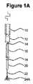
図1Aは、駆動シャフト14を有するマイクロステッパモータ12を駆動する電気回路10を含むエアロゾル発生システムを示す。駆動シャフト14は、電気回路10の電気パルスに応じる駆動シャフト14の回転移動を軸方向移動に転換させる親ねじ16と連結される。親ねじ16は、カプセル20内で可動壁26(図1Aに示されない)を動かすピストン18に接続される。電気回路10のパルスに基づいてマイクロステッパモータ12が駆動することにより、カプセル20内の利用できる容積が、所定の量だけ減少する。カプセル20は、液体エアロゾル形成基体で充填される。パルスに起因する容積の減少によって、対応する量の液体エアロゾル形成基体が、開放ノズル22内に流れ、ここにおいて、液体エアロゾル形成基体は、噴出部24Aを介してノズルから出る。噴出部24Aは、液体エアロゾル形成基体のエアロゾル化を引き起こす。 FIG. 1A shows an aerosol generation system including an
図1B、図1C、および図1Dは、液体エアロゾル形成基体がノズル22を抜け出る時の液体エアロゾル形成基体の異なる取扱いを有するエアロゾル発生システムを示す。 FIGS. 1B, 1C, and 1D show aerosol generating systems with different handling of the liquid aerosol-forming substrate as it exits
図1Bの実施形態では、加熱コイル24Bが、ノズル22の下流に配置され、それはノズル22を抜け出る液体エアロゾル形成基体を直接的に加熱する。 In the embodiment of FIG. 1B,
図1Cの実施形態では、液体透過性構造をもつ平坦なヒーター24Cが、ノズル22の下流に配置され、それはノズル22を抜け出る液体エアロゾル形成基体を直接的に加熱する。 In the embodiment of FIG. 1C, a
図1Dの実施形態では、円錐形のヒーター24Dが、ノズル22の下流に配置され、それはノズル22を抜け出る液体エアロゾル形成基体を直接的に加熱する。 In the embodiment of FIG. 1D, a
図2は、ノズル22の開放している側の詳細を示す。加熱コイル24Bは、ノズル22の開放している側上に取り付けられ、したがって、加熱コイル24Bは、ノズル22から長手方向に延在する。液体エアロゾル形成基体は、ノズル22の開端部において抜け出る。加熱コイル24Bは、エアロゾル形成基体がそこにノズル22によって送達される開放的な内部通路を画定する。加熱コイル24Bは、液体の流れ内に、また液体の流れの周りにあり、したがって、液体エアロゾル形成基体は、直接的に加熱される。加熱コイル24Bは、長さL、直径D、およびノズル22と重なり合う部分Oをもつ。 FIG. 2 shows details of the open side of
図3Aは、ノズル22の開放している側の詳細を示す。円錐形のヒーター24Dは、ノズル22の開放している側の下流に取り付けられ、したがって、円錐形のヒーター24Dは、ノズル22から長手方向に延在する。液体エアロゾル形成基体は、ノズル22の開端部において抜け出る。円錐形のヒーター24Dは、内部通路を画定し、かつ液体の流れ内に、また液体の流れの周りにあり、したがって、液体エアロゾル形成基体は、直接的に加熱される。円錐形のヒーター24Dのコーン端側とノズル22との間には距離Gが存在する。 FIG. 3A shows details of the open side of
図3Bは、平坦な基体から円錐形のヒーター24Dを製造するための概略図である。円錐形のヒーター24Dは、第一の半径rから第二の半径Rまで増加する半径とともに斜高gを有する。 FIG. 3B is a schematic diagram for fabricating a
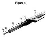
図4は、管状のセグメント22の下流に発熱体24を有する、斜視図における図1B、図1C、および図1Dのエアロゾル発生システムを示す。 FIG. 4 shows the aerosol generation system of FIGS. 1B, 1C, and 1D in perspective view with
図5はエアロゾル発生システムの概略図である。このエアロゾル発生システムは、主要ユニット30と、別個のカートリッジ40と、を含む。主要ユニット30は、駆動シャフト14を有するマイクロステッパモータ12を含む。カートリッジ40は、液体貯蔵部分に相当するカプセルを含む。主要ユニット30は、管状のセグメント22と、液体貯蔵部分から気化器の方へ延在する管状のセグメント22を介して液体エアロゾル形成基体を受ける気化器24と、をさらに備える。気化器24は、液体エアロゾル形成基体が管状のセグメント22を抜け出た後に、液体エアロゾル形成基体を直接的に加熱するように構成される。 FIG. 5 is a schematic diagram of an aerosol generation system. This aerosol generation system includes a
さらに、カートリッジ40は、駆動シャフト14に連結される親ねじ16と、その親ねじ16によって軸方向に移動するピストン18と、を含む。液体貯蔵部分は、液体貯蔵部分をカートリッジのカプセルの内部に残留する構成要素から分離する可動壁26を含む。 In addition,
カートリッジ40は、主要ユニット30内のくぼみ内に受けられるように構成される。カートリッジ40は、カートリッジ40内に提供されたエアロゾル形成基体が消耗した時に、ユーザーによって交換可能であるべきである。新しいカートリッジ40を挿入する時、主要ユニット30におけるスライダーが移動して、くぼみを露出しうる。新しいカートリッジ40は、露出したくぼみ内に挿入されうる。カートリッジ40の親ねじ16は、マイクロステッパモータ12の駆動シャフト14を受けるための開口部を含む。カートリッジ40のカプセルは、管状のセグメント22の端部を受けるための出口を含む。
主要ユニット30は携帯型で、従来的な葉巻たばこまたは紙巻たばこに匹敵するサイズをもつ。主要ユニット30は、本体およびマウスピース部分を含む。主要ユニット30は、電源(例えば、リン酸鉄リチウム電池などの電池)、電気回路10、およびくぼみを含む。電気コネクターが、本体の側部に提供され、それは電気回路10および電池との間に電気的接続を提供する。マウスピース部分は、複数の空気吸込み口および空気出口を含む。使用時に、ユーザーは出口を吸うかまたは吸入して、空気を空気吸込み口からマウスピース部分を通して出口に引き出し、その後、ユーザーの口または肺に入る。内部バッフルが、提供され、それはマウスピース部分を通してカートリッジを通過する空気の流れを強制する。 The
上述の例示的な実施形態は例証するが限定はしない。上記で考察した例示的な実施形態に照らすことにより、上記の例示的な実施形態と一貫したその他の実施形態は今や当業者には明らかとなろう。 The exemplary embodiments described above are illustrative but not limiting. Other embodiments consistent with the above-described exemplary embodiments will now be apparent to those of ordinary skill in the art in light of the exemplary embodiments discussed above.
Claims (14)
Translated fromJapanese前記主要ユニットと取り外し可能なように結合されたカートリッジと、
前記主要ユニットに提供された電源と、
液体エアロゾル形成基体を保存するための液体貯蔵部分であって、可動壁、出口、および前記出口に接続される一方向の弁を含む、前記カートリッジに提供された液体貯蔵部分と、
開放的な内部通路を画定する構造をもつ発熱体を含む気化器と、
液体エアロゾル形成基体を前記液体貯蔵部分の前記出口から直接的に前記発熱体の前記内部通路に送達するように構成されるポンプであって、
マイクロステッパモータの1ステップの実行に伴って所定の数回転するように構成される駆動シャフトをもつ、前記主要ユニットに提供された前記マイクロステッパモータと、
前記可動壁に接続されるピストンと、
前記駆動シャフトを前記ピストンに接続し、前記駆動シャフトの回転を前記ピストンの軸方向移動および前記可動壁の対応する軸方向移動に転換するように構成される親ねじと、を含む、ポンプと、を含み、
前記気化器が、前記内部通路内に前記送達された液体エアロゾル形成基体を、前記送達された液体エアロゾル形成基体の少なくとも一部分を揮発するのに十分な温度に加熱するように構成される、エアロゾル発生システム。main unit and
a cartridge removably coupled to the main unit;
a power source provided to the main unit;
a liquid reservoir provided in said cartridge for storing a liquid aerosol-forming substrate, said liquid reservoir comprising a movable wall, an outlet, and a one-way valve connected to said outlet;
a vaporizer including a heating element having a structure defining an open interior passage;
A pump configured to deliver a liquid aerosol-forming substrate from the outlet of the liquid storage portion directly to the internal passageway of the heating element, comprising:
said microstepper motor provided in said main unit having a drive shaft configured to make a predetermined number of revolutions with execution of one step of the microstepper motor;
a piston connected to the movable wall;
a lead screw connecting the drive shaft to the piston and configured to translate rotation of the drive shaft into axial movement of the piston and corresponding axial movement of the movable wall; including
Aerosol generation, wherein the vaporizer is configured to heat the delivered liquid aerosol-forming substrate within the internal passageway to a temperature sufficient to volatilize at least a portion of the delivered liquid aerosol-forming substrate. system.
Priority Applications (1)
| Application Number | Priority Date | Filing Date | Title |
|---|---|---|---|
| JP2021121241AJP2021182924A (en) | 2015-12-22 | 2021-07-26 | Aerosol generation system comprising motor |
Applications Claiming Priority (3)
| Application Number | Priority Date | Filing Date | Title |
|---|---|---|---|
| EP15202139.0 | 2015-12-22 | ||
| EP15202139 | 2015-12-22 | ||
| PCT/EP2016/079944WO2017108394A1 (en) | 2015-12-22 | 2016-12-06 | Aerosol-generating system with motor |
Related Child Applications (1)
| Application Number | Title | Priority Date | Filing Date |
|---|---|---|---|
| JP2021121241ADivisionJP2021182924A (en) | 2015-12-22 | 2021-07-26 | Aerosol generation system comprising motor |
Publications (2)
| Publication Number | Publication Date |
|---|---|
| JP2019505177A JP2019505177A (en) | 2019-02-28 |
| JP7123793B2true JP7123793B2 (en) | 2022-08-23 |
Family
ID=54979568
Family Applications (2)
| Application Number | Title | Priority Date | Filing Date |
|---|---|---|---|
| JP2018529112AActiveJP7123793B2 (en) | 2015-12-22 | 2016-12-06 | Aerosol generation system with motor |
| JP2021121241AAbandonedJP2021182924A (en) | 2015-12-22 | 2021-07-26 | Aerosol generation system comprising motor |
Family Applications After (1)
| Application Number | Title | Priority Date | Filing Date |
|---|---|---|---|
| JP2021121241AAbandonedJP2021182924A (en) | 2015-12-22 | 2021-07-26 | Aerosol generation system comprising motor |
Country Status (10)
| Country | Link |
|---|---|
| US (2) | US12115307B2 (en) |
| EP (1) | EP3393559B1 (en) |
| JP (2) | JP7123793B2 (en) |
| KR (1) | KR102667961B1 (en) |
| CN (1) | CN108367128B (en) |
| CA (1) | CA3005687A1 (en) |
| IL (1) | IL259244B (en) |
| MX (1) | MX2018007402A (en) |
| RU (1) | RU2721962C2 (en) |
| WO (1) | WO2017108394A1 (en) |
Families Citing this family (44)
| Publication number | Priority date | Publication date | Assignee | Title |
|---|---|---|---|---|
| US20160345631A1 (en) | 2005-07-19 | 2016-12-01 | James Monsees | Portable devices for generating an inhalable vapor |
| US10279934B2 (en) | 2013-03-15 | 2019-05-07 | Juul Labs, Inc. | Fillable vaporizer cartridge and method of filling |
| USD842536S1 (en) | 2016-07-28 | 2019-03-05 | Juul Labs, Inc. | Vaporizer cartridge |
| USD825102S1 (en) | 2016-07-28 | 2018-08-07 | Juul Labs, Inc. | Vaporizer device with cartridge |
| US20160366947A1 (en) | 2013-12-23 | 2016-12-22 | James Monsees | Vaporizer apparatus |
| US10058129B2 (en) | 2013-12-23 | 2018-08-28 | Juul Labs, Inc. | Vaporization device systems and methods |
| DE202014011260U1 (en) | 2013-12-23 | 2018-11-13 | Juul Labs Uk Holdco Limited | Systems for an evaporation device |
| US10076139B2 (en) | 2013-12-23 | 2018-09-18 | Juul Labs, Inc. | Vaporizer apparatus |
| US10159282B2 (en) | 2013-12-23 | 2018-12-25 | Juul Labs, Inc. | Cartridge for use with a vaporizer device |
| MX394125B (en) | 2014-12-05 | 2025-03-24 | Juul Labs Inc | CALIBRATED DOSE CONTROL |
| JP7123793B2 (en)* | 2015-12-22 | 2022-08-23 | フィリップ・モーリス・プロダクツ・ソシエテ・アノニム | Aerosol generation system with motor |
| EP3413960B1 (en) | 2016-02-11 | 2021-03-31 | Juul Labs, Inc. | Fillable vaporizer cartridge and method of filling |
| CO2018009342A2 (en) | 2016-02-11 | 2018-09-20 | Juul Labs Inc | Secure fixing cartridges for vaporizing devices |
| US10405582B2 (en) | 2016-03-10 | 2019-09-10 | Pax Labs, Inc. | Vaporization device with lip sensing |
| USD849996S1 (en) | 2016-06-16 | 2019-05-28 | Pax Labs, Inc. | Vaporizer cartridge |
| USD851830S1 (en) | 2016-06-23 | 2019-06-18 | Pax Labs, Inc. | Combined vaporizer tamp and pick tool |
| USD836541S1 (en) | 2016-06-23 | 2018-12-25 | Pax Labs, Inc. | Charging device |
| CN120531201A (en) | 2016-08-05 | 2025-08-26 | 尤尔实验室有限公司 | Evaporator air speed auxiliary control |
| CN106108121A (en) | 2016-08-15 | 2016-11-16 | 卓尔悦欧洲控股有限公司 | A kind of electronic cigarette |
| US10667558B2 (en) | 2016-11-29 | 2020-06-02 | Altria Client Services Llc | Vaporizer for an aerosol-generating system and vaporizing method |
| EP3548128B1 (en) | 2016-11-29 | 2022-08-24 | Philip Morris Products S.A. | Aerosol-generating system with adjustable pump flow rate |
| JP6945629B2 (en) | 2016-12-12 | 2021-10-06 | ブイエムアール・プロダクツ・リミテッド・ライアビリティ・カンパニーVmr Products Llc | Vaporizer cartridge |
| US12194231B2 (en) | 2016-12-16 | 2025-01-14 | Altria Client Services Llc | Aerosol-generating system with fluid sensor |
| JP2022010186A (en)* | 2017-02-03 | 2022-01-14 | 株式会社三洋物産 | Game machine |
| JP2022010187A (en)* | 2017-02-03 | 2022-01-14 | 株式会社三洋物産 | Game machine |
| CA3066408A1 (en) | 2017-06-10 | 2018-12-13 | Eyenovia, Inc. | Methods and devices for handling a fluid and delivering the fluid to the eye |
| KR102651685B1 (en)* | 2017-08-11 | 2024-03-28 | 필립모리스 프로덕츠 에스.에이. | steam insert |
| USD887632S1 (en) | 2017-09-14 | 2020-06-16 | Pax Labs, Inc. | Vaporizer cartridge |
| CA3081145A1 (en)* | 2017-12-14 | 2019-06-20 | Jt International S.A. | Electronic cigarette |
| GB201808483D0 (en) | 2018-05-23 | 2018-07-11 | Nicoventures Trading Ltd | Electronic vapour provision system with aerosolisable substrate material dispensing arrangement |
| WO2019237052A1 (en) | 2018-06-07 | 2019-12-12 | Juul Labs, Inc. | Cartridges for vaporizer devices |
| CA3110469A1 (en) | 2018-08-22 | 2020-02-27 | Respira Technologies, Inc. | Electronic device for producing an aerosol for inhalation by a person |
| US11413409B2 (en) | 2018-09-12 | 2022-08-16 | Juul Labs, Inc. | Vaporizer including positive temperature coefficient of resistivity (PTCR) heating element |
| CN109568738A (en)* | 2019-02-02 | 2019-04-05 | 上海方予健康医药科技有限公司 | Atomized medicine introducing device and its system |
| CA3164288A1 (en)* | 2019-12-11 | 2021-06-17 | Eyenovia, Inc. | Systems and devices for delivering fluids to the eye and methods of use |
| CN111150113B (en)* | 2020-01-08 | 2022-11-01 | 深圳市施美乐科技股份有限公司 | Electric heating suction device |
| US11109622B1 (en)* | 2020-03-30 | 2021-09-07 | Gofire, Inc. | System and method for metered dosing vaporizer |
| EP3981266B1 (en) | 2020-10-06 | 2023-07-19 | JT International SA | Aerosol generation device with ejection mechanism using leverage |
| WO2022106541A1 (en)* | 2020-11-18 | 2022-05-27 | Jt International Sa | Electronic smoking device with liquid reservoir |
| CN112586810A (en)* | 2020-12-25 | 2021-04-02 | 云南中烟工业有限责任公司 | Rotary electronic cigarette capable of quantitatively supplying gel-state tobacco tar |
| US20230337735A1 (en) | 2022-04-22 | 2023-10-26 | Qnovia, Inc. | Electronic devices for aerosolizing and inhaling liquid |
| CN117256948A (en)* | 2022-06-14 | 2023-12-22 | 海南摩尔兄弟科技有限公司 | Electronic atomizing device |
| KR102824247B1 (en)* | 2022-11-02 | 2025-06-24 | 주식회사 케이티앤지 | Inhaler |
| WO2025120312A1 (en)* | 2023-12-05 | 2025-06-12 | Nicoventures Trading Limited | Aerosol delivery subsystems and methods |
Citations (6)
| Publication number | Priority date | Publication date | Assignee | Title |
|---|---|---|---|---|
| WO2008015918A1 (en) | 2006-08-01 | 2008-02-07 | Japan Tobacco Inc. | Aerosol suction device, and its sucking method |
| WO2013027249A1 (en) | 2011-08-19 | 2013-02-28 | 日本たばこ産業株式会社 | Aerosol aspirator |
| US20150114409A1 (en) | 2013-10-31 | 2015-04-30 | R.J. Reynolds Tobacco Company | Aerosol Delivery Device Including a Bubble Jet Head and Related Method |
| US20150216237A1 (en) | 2014-01-22 | 2015-08-06 | E-Nicotine Technology, Inc. | Methods and devices for smoking urge relief |
| JP2019505192A (en) | 2015-12-22 | 2019-02-28 | フィリップ・モーリス・プロダクツ・ソシエテ・アノニム | An electrically operated aerosol generation system with a liquid pump |
| JP2019505179A (en) | 2015-12-22 | 2019-02-28 | フィリップ・モーリス・プロダクツ・ソシエテ・アノニム | Aerosol generation system with pump |
Family Cites Families (134)
| Publication number | Priority date | Publication date | Assignee | Title |
|---|---|---|---|---|
| US5743251A (en) | 1996-05-15 | 1998-04-28 | Philip Morris Incorporated | Aerosol and a method and apparatus for generating an aerosol |
| KR100289448B1 (en)* | 1997-07-23 | 2001-05-02 | 미즈노 마사루 | Flavor generator |
| US6063339A (en)* | 1998-01-09 | 2000-05-16 | Cartesian Technologies, Inc. | Method and apparatus for high-speed dot array dispensing |
| US6501052B2 (en)* | 2000-12-22 | 2002-12-31 | Chrysalis Technologies Incorporated | Aerosol generator having multiple heating zones and methods of use thereof |
| US20080038363A1 (en)* | 2001-05-24 | 2008-02-14 | Zaffaroni Alejandro C | Aerosol delivery system and uses thereof |
| CN1700934B (en)* | 2002-09-06 | 2011-08-03 | 菲利普莫里斯美国公司 | Liquid aerosol preparation and aerosol generating device and method for preparing aerosol |
| US7849850B2 (en)* | 2003-02-28 | 2010-12-14 | Battelle Memorial Institute | Nozzle for handheld pulmonary aerosol delivery device |
| CN100381083C (en)* | 2003-04-29 | 2008-04-16 | 韩力 | Non-combustible electronic spray cigarette |
| JP4869927B2 (en)* | 2003-08-04 | 2012-02-08 | アレックザ ファーマシューティカルズ, インコーポレイテッド | Substrates and preparation methods and uses for drug delivery devices |
| US9675109B2 (en)* | 2005-07-19 | 2017-06-13 | J. T. International Sa | Method and system for vaporization of a substance |
| US9155848B2 (en)* | 2007-10-15 | 2015-10-13 | Vapir, Inc. | Method and system for vaporization of a substance |
| US8851068B2 (en)* | 2009-04-21 | 2014-10-07 | Aj Marketing Llc | Personal inhalation devices |
| EP2253233A1 (en)* | 2009-05-21 | 2010-11-24 | Philip Morris Products S.A. | An electrically heated smoking system |
| US20100181387A1 (en)* | 2009-12-01 | 2010-07-22 | Zaffaroni Alejandro C | Aerosol delivery system and uses thereof |
| US9999250B2 (en)* | 2010-05-15 | 2018-06-19 | Rai Strategic Holdings, Inc. | Vaporizer related systems, methods, and apparatus |
| US9743691B2 (en)* | 2010-05-15 | 2017-08-29 | Rai Strategic Holdings, Inc. | Vaporizer configuration, control, and reporting |
| SMT202000393T1 (en)* | 2010-08-24 | 2020-09-10 | Jt Int Sa | Inhalation device including substance usage controls |
| US8499766B1 (en)* | 2010-09-15 | 2013-08-06 | Kyle D. Newton | Electronic cigarette with function illuminator |
| KR20140063506A (en)* | 2011-02-09 | 2014-05-27 | 새미 카푸아노 | Variable power control electronic cigarette |
| KR102177660B1 (en)* | 2011-08-16 | 2020-11-12 | 쥴 랩스, 인크. | Low temperature electronic vaporization device and methods |
| US20140107815A1 (en)* | 2011-09-14 | 2014-04-17 | The Safe Cig, Llc | Electronically augmented container for storing and interfacing with vapor delivery devices |
| US8820330B2 (en)* | 2011-10-28 | 2014-09-02 | Evolv, Llc | Electronic vaporizer that simulates smoking with power control |
| US20140334804A1 (en)* | 2012-03-26 | 2014-11-13 | Enbright Co., Ltd. | Atomization control unit and a portable atomizing apparatus having the same |
| KR101930663B1 (en)* | 2012-04-12 | 2018-12-18 | 제이티 인터내셔널 소시에떼 아노님 | Aerosol-generating devices |
| US20130340775A1 (en)* | 2012-04-25 | 2013-12-26 | Bernard Juster | Application development for a network with an electronic cigarette |
| US20130284192A1 (en)* | 2012-04-25 | 2013-10-31 | Eyal Peleg | Electronic cigarette with communication enhancements |
| GB2504076A (en)* | 2012-07-16 | 2014-01-22 | Nicoventures Holdings Ltd | Electronic smoking device |
| CN204682523U (en)* | 2012-08-21 | 2015-10-07 | 惠州市吉瑞科技有限公司 | Electronic cigarette device |
| US8881737B2 (en)* | 2012-09-04 | 2014-11-11 | R.J. Reynolds Tobacco Company | Electronic smoking article comprising one or more microheaters |
| US10021906B2 (en)* | 2012-09-10 | 2018-07-17 | Healthier Choices Management Corp. | Electronic pipe with modified heat source |
| PT2892370T (en)* | 2012-09-10 | 2017-02-10 | Ght Global Heating Tech Ag | Device for vaporizing liquid for inhalation |
| GB2507103A (en)* | 2012-10-19 | 2014-04-23 | Nicoventures Holdings Ltd | Electronic inhalation device |
| GB2507102B (en)* | 2012-10-19 | 2015-12-30 | Nicoventures Holdings Ltd | Electronic inhalation device |
| US10058122B2 (en)* | 2012-10-25 | 2018-08-28 | Matthew Steingraber | Electronic cigarette |
| US20140123989A1 (en)* | 2012-11-05 | 2014-05-08 | The Safe Cig, Llc | Device and method for vaporizing a fluid |
| US9675114B2 (en)* | 2012-11-08 | 2017-06-13 | Ludovicus Josephine Felicien Timmermans | Real time variable voltage programmable electronic cigarette and method |
| CN102940313B (en)* | 2012-11-13 | 2015-04-01 | 卓尔悦(常州)电子科技有限公司 | Intelligent controller and intelligent control method for electronic cigarette |
| US20140174459A1 (en)* | 2012-12-21 | 2014-06-26 | Vapor Innovations, LLC | Smart Electronic Cigarette |
| WO2014125479A1 (en)* | 2013-02-12 | 2014-08-21 | Sis Resources Ltd. | Inductive charging for an electronic cigarette |
| CN104026742A (en)* | 2013-03-05 | 2014-09-10 | 向智勇 | Heating control method and device for electronic cigarette |
| MX2015013513A (en) | 2013-03-22 | 2016-10-26 | Altria Client Services Llc | Electronic smoking article. |
| CA2907731A1 (en) | 2013-03-22 | 2014-09-25 | Altria Client Services Llc | Electronic smoking article |
| CN104106841A (en)* | 2013-04-15 | 2014-10-22 | 惠州市吉瑞科技有限公司 | Electronic cigarette case |
| CN104242372B (en)* | 2013-06-05 | 2018-05-22 | 惠州市吉瑞科技有限公司 | The charging method and electronic cigarette packet of electronic cigarette |
| US20150075546A1 (en)* | 2013-07-12 | 2015-03-19 | Stoicheion Technology LLC | Controller With Network Access and Unique ID for Personal Electronic Devices |
| US10251423B2 (en)* | 2013-09-13 | 2019-04-09 | Nicodart, Inc. | Programmable electronic vaporizing apparatus and smoking cessation system |
| MY175605A (en)* | 2013-09-30 | 2020-07-01 | Japan Tobacco Inc | Non-burning type flavor inhaler |
| US20150122252A1 (en)* | 2013-11-01 | 2015-05-07 | Kevin FRIJA | Hand-held personal vaporizer |
| GB201320834D0 (en)* | 2013-11-26 | 2014-01-08 | Guise Andrew | Pulmonary delivery devices |
| US20150224268A1 (en)* | 2014-02-07 | 2015-08-13 | R.J. Reynolds Tobacco Company | Charging Accessory Device for an Aerosol Delivery Device and Related System, Method, Apparatus, and Computer Program Product for Providing Interactive Services for Aerosol Delivery Devices |
| US9980515B2 (en)* | 2014-02-12 | 2018-05-29 | Vapor 4 Life, LLC | Mouthpiece assembly for an electronic cigar or cigarette |
| WO2015127429A1 (en)* | 2014-02-24 | 2015-08-27 | Arash Sabet | Electronic cigarette charging systems integration with cell phone case |
| US20170045994A1 (en)* | 2014-02-28 | 2017-02-16 | Beyond Twenty Ltd. | Electronic vaporiser system |
| EP2915443B1 (en)* | 2014-03-03 | 2019-08-14 | Fontem Holdings 1 B.V. | Electronic smoking device |
| US9597466B2 (en)* | 2014-03-12 | 2017-03-21 | R. J. Reynolds Tobacco Company | Aerosol delivery system and related method, apparatus, and computer program product for providing control information to an aerosol delivery device via a cartridge |
| US11696604B2 (en)* | 2014-03-13 | 2023-07-11 | Rai Strategic Holdings, Inc. | Aerosol delivery device and related method and computer program product for controlling an aerosol delivery device based on input characteristics |
| CN103876288A (en)* | 2014-03-18 | 2014-06-25 | 刘秋明 | Electronic-cigarette tobacco tar atomizing method and electronic-cigarette control circuit |
| WO2015139272A1 (en)* | 2014-03-20 | 2015-09-24 | 吉瑞高新科技股份有限公司 | Method for preventing a child from accidentally puffing an electronic cigarette |
| WO2015149326A1 (en)* | 2014-04-03 | 2015-10-08 | 吉瑞高新科技股份有限公司 | Information interaction method and system for electronic cigarette |
| CA2985988C (en)* | 2014-05-12 | 2021-05-25 | Loto Labs, Inc. | Improved vaporizer device |
| CN104055224B (en)* | 2014-06-09 | 2017-01-11 | 矽力杰半导体技术(杭州)有限公司 | Integrated circuit for electronic cigarette and electronic cigarette |
| WO2015192084A1 (en)* | 2014-06-14 | 2015-12-17 | Evolv, Llc | Electronic vaporizer having temperature sensing and limit |
| CN104049550B (en)* | 2014-06-19 | 2017-09-26 | 卓尔悦欧洲控股有限公司 | Control method and device of multi-output mode electronic cigarette |
| IL273507B2 (en)* | 2014-06-30 | 2024-06-01 | Syqe Medical Ltd | Methods, devices and systems for administering active substances through the lungs |
| US10888119B2 (en)* | 2014-07-10 | 2021-01-12 | Rai Strategic Holdings, Inc. | System and related methods, apparatuses, and computer program products for controlling operation of a device based on a read request |
| WO2016029426A1 (en)* | 2014-08-29 | 2016-03-03 | 惠州市吉瑞科技有限公司 | Data communication method and data communication system |
| ES3027188T3 (en)* | 2014-10-02 | 2025-06-13 | Cue Vapor Ltd | Disposable tank electronic cigarette, method of manufacture and method of use |
| WO2016090037A1 (en)* | 2014-12-02 | 2016-06-09 | Goldstein Gabriel Marc | Vaporizing reservoir |
| CN104571190B (en)* | 2015-01-22 | 2017-05-10 | 卓尔悦欧洲控股有限公司 | Temperature control system and electronic cigarette thereof |
| US10123564B2 (en)* | 2015-05-12 | 2018-11-13 | Lunatech, Llc | Electronic vapor devices configured to dispense colored vapor |
| US10039320B2 (en)* | 2015-05-14 | 2018-08-07 | Lunatech, Llc | Multi-chambered vaporizer and blend control |
| US20160337362A1 (en)* | 2015-05-15 | 2016-11-17 | Lunatech, Llc | Remote access authorization for use of vapor device |
| US20160331859A1 (en)* | 2015-05-15 | 2016-11-17 | Lunatech, Llc | Aerosol regulation and control using an electronic vaporizing and sensing device |
| WO2016187107A1 (en)* | 2015-05-15 | 2016-11-24 | John Cameron | Vaporizer with logic need based messaging platform |
| WO2016187110A1 (en)* | 2015-05-15 | 2016-11-24 | John Cameron | Electronic vapor device in cooperation with wireless communication device |
| US20160338407A1 (en)* | 2015-05-18 | 2016-11-24 | Andrew Kerdemelidis | Programmable vaporizer device and method |
| US10362803B2 (en)* | 2015-06-10 | 2019-07-30 | Evolv, Llc | Electronic vaporizer having reduced particle size |
| US20160363917A1 (en)* | 2015-06-11 | 2016-12-15 | Lunatech, Llc | User Interface For An Analysis And Vapor Dispensing Apparatus |
| GB201511349D0 (en)* | 2015-06-29 | 2015-08-12 | Nicoventures Holdings Ltd | Electronic aerosol provision systems |
| GB201511358D0 (en)* | 2015-06-29 | 2015-08-12 | Nicoventures Holdings Ltd | Electronic aerosol provision systems |
| EP3318140A4 (en)* | 2015-07-02 | 2019-03-06 | Changzhou Jwei Intelligent Technology Co., Ltd. | Power supply device, aerosol-generating device, and identification control method thereof |
| EP3319466B1 (en)* | 2015-07-10 | 2025-08-13 | Juul Labs, Inc. | Wickless vaporizing devices and methods |
| FR3039040B1 (en)* | 2015-07-20 | 2017-08-25 | Innovi | DEVICE FOR THE CONTROLLED SUPPLY OF A DRILL IN AN E-CIGARETTE, E-CIGARETTE OBTAINED |
| US20170042230A1 (en)* | 2015-08-10 | 2017-02-16 | Lunatech, Llc | Intuitive Interface For Electronic Vaporizing Device |
| US20170046357A1 (en)* | 2015-08-10 | 2017-02-16 | Lunatech, Llc | Collecting And Providing Data For Electronic Vaporizers |
| US20170046738A1 (en)* | 2015-08-10 | 2017-02-16 | Lunatech, Llc | System And Method For Providing An E-Vapor Club |
| US20170042231A1 (en)* | 2015-08-11 | 2017-02-16 | Lunatech, Llc | Demonstrative interface for electronic vaporizing device |
| US9943111B2 (en)* | 2015-08-31 | 2018-04-17 | Lunatech, Llc | Methods and systems for vapor cooling |
| CN205199822U (en)* | 2015-09-22 | 2016-05-04 | 深圳市杰仕博科技有限公司 | A battery device for electronic fog spinning disk atomiser |
| US20170093981A1 (en)* | 2015-09-24 | 2017-03-30 | Lunatech, Llc | Monocle Communication Evapor Device |
| US20170086504A1 (en)* | 2015-09-24 | 2017-03-30 | Lunatech, Llc | Evapor Mask Delivery System |
| US20170086496A1 (en)* | 2015-09-24 | 2017-03-30 | Lunatech, Llc | Electronic Vapor Device Multitool |
| US20170086497A1 (en)* | 2015-09-24 | 2017-03-30 | Lunatech, Llc | Methods And Systems For Vaping And Presenting Audio |
| US9936736B2 (en)* | 2015-09-24 | 2018-04-10 | Lunatech, Llc | Battery system for electronic vapor communication device |
| US20170093960A1 (en)* | 2015-09-24 | 2017-03-30 | Lunatech, Llc | Vapor Device Ecosystem |
| US20170091490A1 (en)* | 2015-09-24 | 2017-03-30 | Lunatech, Llc | Methods And Systems For Displaying Private Information |
| US10085486B2 (en)* | 2015-09-24 | 2018-10-02 | Lunatech, Llc | Electronic vapor device with film assembly |
| US20170092106A1 (en)* | 2015-09-24 | 2017-03-30 | Lunatech, Llc | Methods And Systems For Locating Devices |
| WO2017058922A1 (en)* | 2015-09-28 | 2017-04-06 | Lubby Holdings Llc | Vaporizer and detachable power source |
| US20170303580A1 (en)* | 2016-04-25 | 2017-10-26 | Lunatech, Llc | Natural-based liquid composition and electronic vaporizing devices for using such composition |
| US9936737B2 (en)* | 2015-10-28 | 2018-04-10 | Lunatech, Llc | Methods and systems for a dual function vapor device |
| US9943116B2 (en)* | 2015-11-17 | 2018-04-17 | Lunatech, Llc | Electronic vapor device warning system |
| US20170135407A1 (en)* | 2015-11-17 | 2017-05-18 | Lunatech, Llc | Voice responsive electronic vapor system |
| US10039327B2 (en)* | 2015-11-17 | 2018-08-07 | Lunatech, Llc | Computing device with enabled electronic vapor device |
| US20170136193A1 (en)* | 2015-11-17 | 2017-05-18 | Lunatech, Llc | Next generation electronic vapor device |
| US9936738B2 (en)* | 2015-11-17 | 2018-04-10 | Lunatech, Llc | Methods and systems for smooth vapor delivery |
| WO2017087612A1 (en)* | 2015-11-17 | 2017-05-26 | John Cameron | Portable wireless electronic vapor device |
| US20170136194A1 (en)* | 2015-11-17 | 2017-05-18 | Lunatech, Llc | Electronic vapor device enabled aromatic distribution system |
| US20170136301A1 (en)* | 2015-11-17 | 2017-05-18 | Lunatech, Llc | Electronic vapor device enabled exercise system |
| US20170135412A1 (en)* | 2015-11-17 | 2017-05-18 | Lunatech, Llc | Advanced microprocessor for electronic vapor device |
| US20170150756A1 (en)* | 2015-11-30 | 2017-06-01 | National Concessions Group Inc. | Dual-activation for vaporizer devices |
| US10624392B2 (en)* | 2015-12-22 | 2020-04-21 | Altria Client Services Llc | Aerosol-generating system with motor |
| JP7123793B2 (en)* | 2015-12-22 | 2022-08-23 | フィリップ・モーリス・プロダクツ・ソシエテ・アノニム | Aerosol generation system with motor |
| US20170181474A1 (en)* | 2015-12-28 | 2017-06-29 | Lunatech, Llc | Methods and Systems For Substance Reduction Via Electronic Vapor Device Delivery |
| US20170185364A1 (en)* | 2015-12-28 | 2017-06-29 | Lunatech, Llc | Methods and Systems For a Dual Function Multimedia Device |
| US20170181467A1 (en)* | 2015-12-28 | 2017-06-29 | Lunatech, Llc | Methods and systems for a dual function gaming device |
| US20170181475A1 (en)* | 2015-12-28 | 2017-06-29 | Lunatech, Llc | Methods and Systems For Gradual Substance Reduction |
| CN105717812B (en)* | 2016-01-25 | 2019-03-29 | 深圳市合元科技有限公司 | A kind of Intelligentized control method based on electronic cigarette, control system and electronic cigarette |
| WO2017139646A1 (en)* | 2016-02-12 | 2017-08-17 | Mark Anton | Programmable electronic inhalation device |
| US10506829B2 (en)* | 2016-02-26 | 2019-12-17 | Freelander Innovations USA, LLC | System and method for a vaporizer |
| US10405582B2 (en)* | 2016-03-10 | 2019-09-10 | Pax Labs, Inc. | Vaporization device with lip sensing |
| US10231486B2 (en)* | 2016-03-10 | 2019-03-19 | Pax Labs, Inc. | Vaporization device having integrated games |
| US9936734B2 (en)* | 2016-03-11 | 2018-04-10 | Altria Client Services, Llc. | Personal carrying case for electronic vaping device |
| US10212970B2 (en)* | 2016-03-23 | 2019-02-26 | Elise Barbuck | Vaporizer adapter for a rolled article |
| US10334882B2 (en)* | 2016-04-13 | 2019-07-02 | Md&C Creative Masion Sa | Electronic cigarette |
| US20170303590A1 (en)* | 2016-04-25 | 2017-10-26 | Lunatech, Llc | Electronic vaporizing device with weather detection functionality |
| US10127741B2 (en)* | 2016-04-25 | 2018-11-13 | Lunatech, Llc | Electronic vaporizing device with vehicle monitoring functionality |
| US20170303593A1 (en)* | 2016-04-25 | 2017-10-26 | Lunatech, Llc | Electronic vaporizing device with security monitoring functionality |
| US20170332702A1 (en)* | 2016-05-20 | 2017-11-23 | Lunatech, Llc | Electronic vaporizing device with messaging functionality |
| US9894938B2 (en)* | 2016-06-30 | 2018-02-20 | MagSOL Labs | E-cigarette smart phone attachment |
| CN206227716U (en)* | 2016-09-14 | 2017-06-09 | 深圳市合元科技有限公司 | The atomizer and electronic cigarette of electronic cigarette |
| US10517332B2 (en)* | 2017-10-31 | 2019-12-31 | Rai Strategic Holdings, Inc. | Induction heated aerosol delivery device |
| US10750787B2 (en)* | 2018-01-03 | 2020-08-25 | Cqens Technologies Inc. | Heat-not-burn device and method |
| CN207766584U (en)* | 2018-01-31 | 2018-08-24 | 深圳市合元科技有限公司 | A heating device and electronic cigarette |
- 2016
- 2016-12-06JPJP2018529112Apatent/JP7123793B2/enactiveActive
- 2016-12-06EPEP16809733.5Apatent/EP3393559B1/enactiveActive
- 2016-12-06CACA3005687Apatent/CA3005687A1/enactivePending
- 2016-12-06WOPCT/EP2016/079944patent/WO2017108394A1/ennot_activeCeased
- 2016-12-06KRKR1020187015931Apatent/KR102667961B1/enactiveActive
- 2016-12-06MXMX2018007402Apatent/MX2018007402A/enunknown
- 2016-12-06RURU2018126791Apatent/RU2721962C2/enactive
- 2016-12-06CNCN201680072365.2Apatent/CN108367128B/enactiveActive
- 2018
- 2018-05-09ILIL259244Apatent/IL259244B/enunknown
- 2021
- 2021-07-26JPJP2021121241Apatent/JP2021182924A/ennot_activeAbandoned
- 2023
- 2023-04-04USUS18/295,398patent/US12115307B2/enactiveActive
- 2024
- 2024-09-17USUS18/887,517patent/US20250009996A1/enactivePending
Patent Citations (7)
| Publication number | Priority date | Publication date | Assignee | Title |
|---|---|---|---|---|
| WO2008015918A1 (en) | 2006-08-01 | 2008-02-07 | Japan Tobacco Inc. | Aerosol suction device, and its sucking method |
| WO2013027249A1 (en) | 2011-08-19 | 2013-02-28 | 日本たばこ産業株式会社 | Aerosol aspirator |
| US20150114409A1 (en) | 2013-10-31 | 2015-04-30 | R.J. Reynolds Tobacco Company | Aerosol Delivery Device Including a Bubble Jet Head and Related Method |
| US20150117842A1 (en) | 2013-10-31 | 2015-04-30 | R.J. Reynolds Tobacco Company | Aerosol Delivery Device Including a Positive Displacement Aerosol Delivery Mechanism |
| US20150216237A1 (en) | 2014-01-22 | 2015-08-06 | E-Nicotine Technology, Inc. | Methods and devices for smoking urge relief |
| JP2019505192A (en) | 2015-12-22 | 2019-02-28 | フィリップ・モーリス・プロダクツ・ソシエテ・アノニム | An electrically operated aerosol generation system with a liquid pump |
| JP2019505179A (en) | 2015-12-22 | 2019-02-28 | フィリップ・モーリス・プロダクツ・ソシエテ・アノニム | Aerosol generation system with pump |
Also Published As
| Publication number | Publication date |
|---|---|
| RU2018126791A (en) | 2020-01-23 |
| JP2019505177A (en) | 2019-02-28 |
| EP3393559B1 (en) | 2022-03-09 |
| EP3393559A1 (en) | 2018-10-31 |
| US12115307B2 (en) | 2024-10-15 |
| KR102667961B1 (en) | 2024-05-23 |
| CA3005687A1 (en) | 2017-06-29 |
| WO2017108394A1 (en) | 2017-06-29 |
| US20250009996A1 (en) | 2025-01-09 |
| IL259244A (en) | 2018-07-31 |
| US20230239968A1 (en) | 2023-07-27 |
| JP2021182924A (en) | 2021-12-02 |
| RU2721962C2 (en) | 2020-05-25 |
| MX2018007402A (en) | 2018-08-15 |
| RU2018126791A3 (en) | 2020-03-11 |
| CN108367128B (en) | 2022-10-21 |
| IL259244B (en) | 2022-03-01 |
| KR20180095807A (en) | 2018-08-28 |
| CN108367128A (en) | 2018-08-03 |
Similar Documents
| Publication | Publication Date | Title |
|---|---|---|
| JP7123793B2 (en) | Aerosol generation system with motor | |
| US11641695B2 (en) | Aerosol-generating system with motor | |
| KR102664544B1 (en) | Aerosol generating system with pump | |
| JP7311085B2 (en) | electronic aerosol delivery system | |
| JP6937758B2 (en) | An electrically operated aerosol generation system with a liquid pump | |
| KR102282628B1 (en) | Aerosol-generating system with adjustable pump flow rate | |
| JP7267332B2 (en) | Aerosol generating system and method involving dispensing of liquid aerosol-forming substrates by pumped air | |
| EP3855948B1 (en) | Mouthpiece for aerosol-generating device with woven fiber liner |
Legal Events
| Date | Code | Title | Description |
|---|---|---|---|
| A621 | Written request for application examination | Free format text:JAPANESE INTERMEDIATE CODE: A621 Effective date:20191107 | |
| A977 | Report on retrieval | Free format text:JAPANESE INTERMEDIATE CODE: A971007 Effective date:20201124 | |
| A131 | Notification of reasons for refusal | Free format text:JAPANESE INTERMEDIATE CODE: A131 Effective date:20201130 | |
| A02 | Decision of refusal | Free format text:JAPANESE INTERMEDIATE CODE: A02 Effective date:20210510 | |
| A521 | Request for written amendment filed | Free format text:JAPANESE INTERMEDIATE CODE: A523 Effective date:20210726 | |
| C60 | Trial request (containing other claim documents, opposition documents) | Free format text:JAPANESE INTERMEDIATE CODE: C60 Effective date:20210726 | |
| A911 | Transfer to examiner for re-examination before appeal (zenchi) | Free format text:JAPANESE INTERMEDIATE CODE: A911 Effective date:20210812 | |
| C21 | Notice of transfer of a case for reconsideration by examiners before appeal proceedings | Free format text:JAPANESE INTERMEDIATE CODE: C21 Effective date:20210816 | |
| A912 | Re-examination (zenchi) completed and case transferred to appeal board | Free format text:JAPANESE INTERMEDIATE CODE: A912 Effective date:20210903 | |
| C211 | Notice of termination of reconsideration by examiners before appeal proceedings | Free format text:JAPANESE INTERMEDIATE CODE: C211 Effective date:20210908 | |
| C22 | Notice of designation (change) of administrative judge | Free format text:JAPANESE INTERMEDIATE CODE: C22 Effective date:20211101 | |
| C13 | Notice of reasons for refusal | Free format text:JAPANESE INTERMEDIATE CODE: C13 Effective date:20220322 | |
| A521 | Request for written amendment filed | Free format text:JAPANESE INTERMEDIATE CODE: A523 Effective date:20220511 | |
| C22 | Notice of designation (change) of administrative judge | Free format text:JAPANESE INTERMEDIATE CODE: C22 Effective date:20220523 | |
| C23 | Notice of termination of proceedings | Free format text:JAPANESE INTERMEDIATE CODE: C23 Effective date:20220620 | |
| C03 | Trial/appeal decision taken | Free format text:JAPANESE INTERMEDIATE CODE: C03 Effective date:20220713 | |
| C30A | Notification sent | Free format text:JAPANESE INTERMEDIATE CODE: C3012 Effective date:20220713 | |
| A61 | First payment of annual fees (during grant procedure) | Free format text:JAPANESE INTERMEDIATE CODE: A61 Effective date:20220810 | |
| R150 | Certificate of patent or registration of utility model | Ref document number:7123793 Country of ref document:JP Free format text:JAPANESE INTERMEDIATE CODE: R150 |