JP7120878B2 - Work equipment lifting control device - Google Patents
Work equipment lifting control deviceDownload PDFInfo
- Publication number
- JP7120878B2 JP7120878B2JP2018198202AJP2018198202AJP7120878B2JP 7120878 B2JP7120878 B2JP 7120878B2JP 2018198202 AJP2018198202 AJP 2018198202AJP 2018198202 AJP2018198202 AJP 2018198202AJP 7120878 B2JP7120878 B2JP 7120878B2
- Authority
- JP
- Japan
- Prior art keywords
- tractor
- work
- angle
- field
- slope
- Prior art date
- Legal status (The legal status is an assumption and is not a legal conclusion. Google has not performed a legal analysis and makes no representation as to the accuracy of the status listed.)
- Active
Links
- 238000001514detection methodMethods0.000claimsdescription39
- 238000004891communicationMethods0.000description31
- 230000005540biological transmissionEffects0.000description18
- 238000005259measurementMethods0.000description11
- 230000001174ascending effectEffects0.000description6
- 238000013459approachMethods0.000description5
- 239000000446fuelSubstances0.000description4
- 238000002347injectionMethods0.000description4
- 239000007924injectionSubstances0.000description4
- 238000000034methodMethods0.000description4
- 241000209094OryzaSpecies0.000description3
- 235000007164Oryza sativaNutrition0.000description3
- 230000001133accelerationEffects0.000description3
- 238000010586diagramMethods0.000description3
- 230000007246mechanismEffects0.000description3
- 238000012545processingMethods0.000description3
- 235000009566riceNutrition0.000description3
- 230000008859changeEffects0.000description2
- 230000000694effectsEffects0.000description2
- 230000003028elevating effectEffects0.000description2
- 230000006870functionEffects0.000description2
- 230000007935neutral effectEffects0.000description2
- 230000008569processEffects0.000description2
- 206010034719Personality changeDiseases0.000description1
- 230000003416augmentationEffects0.000description1
- 238000002485combustion reactionMethods0.000description1
- 238000000605extractionMethods0.000description1
- 239000003337fertilizerSubstances0.000description1
- 239000002828fuel tankSubstances0.000description1
- 239000003502gasolineSubstances0.000description1
- 230000005764inhibitory processEffects0.000description1
- 230000007704transitionEffects0.000description1
Images


Classifications
- A—HUMAN NECESSITIES
- A01—AGRICULTURE; FORESTRY; ANIMAL HUSBANDRY; HUNTING; TRAPPING; FISHING
- A01B—SOIL WORKING IN AGRICULTURE OR FORESTRY; PARTS, DETAILS, OR ACCESSORIES OF AGRICULTURAL MACHINES OR IMPLEMENTS, IN GENERAL
- A01B63/00—Lifting or adjusting devices or arrangements for agricultural machines or implements
- A01B63/02—Lifting or adjusting devices or arrangements for agricultural machines or implements for implements mounted on tractors
- A01B63/10—Lifting or adjusting devices or arrangements for agricultural machines or implements for implements mounted on tractors operated by hydraulic or pneumatic means
Landscapes
- Life Sciences & Earth Sciences (AREA)
- Engineering & Computer Science (AREA)
- Mechanical Engineering (AREA)
- Soil Sciences (AREA)
- Environmental Sciences (AREA)
- Lifting Devices For Agricultural Implements (AREA)
Description
Translated fromJapanese 本発明は、主として、作業機を昇降可能な作業車両に設けられる作業機昇降制御装置に関する。 BACKGROUND OF THE
特許文献1には、傾斜している圃場の出入口付近を走行する場合であっても、苗植付部が圃場に接触しない構成の田植機が開示されている。この田植機は、走行車両と、苗植付装置と、リフトシリンダと、傾斜センサと、制御装置と、を備える。苗植付装置は、走行車両に対して昇降可能に装着されている。リフトシリンダは、ピストンを動作させることで苗植付装置を昇降させる。傾斜センサは、走行車両の前後方向の傾斜角度を検出する。制御装置は、傾斜センサが所定値以上の角度を検出すると、リフトシリンダに圧油を供給してピストンを動作させて、苗植付装置の高さを上昇させる。
しかし、特許文献1では、圃場の出入り口のスロープの勾配が小さい場合でも的確に検出できるように上記の所定値を小さくした場合、圃場の凹凸等によっても走行車両の傾斜角度が所定値以上になるため、スロープを的確に検出できない。一方、この誤検出を防止するために所定値を大きくした場合、勾配が小さいスロープを検出できない可能性がある。また、スロープを的確に検出することが困難であることは、田植機に限られず、作業機を装着可能な作業車両全般に共通する課題である。 However, in
本発明は以上の事情に鑑みてされたものであり、その主要な目的は、作業機を装着可能な作業車両において、圃場の出入り口のスロープを的確に検出して作業機を昇降させる作業機昇降制御装置を提供することにある。 SUMMARY OF THE INVENTION The present invention has been made in view of the above circumstances, and its main object is to provide a working machine lifting and lowering apparatus for a working vehicle to which a working machine can be attached, in which the slope of the entrance/exit of a field is accurately detected to raise or lower the working machine. The object is to provide a control device.
本発明の解決しようとする課題は以上の如くであり、次にこの課題を解決するための手段とその効果を説明する。 The problems to be solved by the present invention are as described above. Next, the means for solving the problems and the effects thereof will be described.
本発明の第1の観点によれば、以下の構成の作業機昇降制御装置が提供される。作業機昇降制御装置は、角度センサと、位置検出部と、角度判定部と、位置判定部と、位置算出部と、昇降制御部と、を備える。前記角度センサは、前記作業車両の前部が上方に移動する回転方向を正とした当該作業車両のピッチ角を検出する。前記位置検出部は、衛星測位システムを用いて前記作業車両の位置を検出する。前記角度判定部は、前記角度センサが検出した前記ピッチ角が第1所定角度より大きいか否かを判定する。前記位置判定部は、前記ピッチ角が前記第1所定角度より大きいと前記角度判定部が判定した場合、前記作業車両の現在位置から、圃場よりも高い位置にある圃場外部と圃場とを接続するスロープまでの距離が閾値以下であるかを判定する。前記位置算出部は、前記距離が閾値以下であると前記位置判定部が判定した場合、前記作業機を上昇させる上昇開始位置を決定する。前記昇降制御部は、前記圃場から前記圃場外部に向かう際に、前記作業車両の位置が前記上昇開始位置に到達した場合に、前記作業機を退避位置まで上昇させる。According to afirst aspect of the present invention, there is provided a working machine lifting control device having the following configuration. The work machine elevation control device includes an angle sensor, a position detection section, an angle determination section, a position determination section, aposition calculation section, and an elevation control section. The angle sensor detects the pitch angle of the work vehicle, with the rotation direction in which the front portion of the work vehicle moves upward as the positive direction. The position detection unit detects the position of the work vehicle using a satellite positioning system. The angle determination unit determines whether the pitch angle detected by the angle sensor is greater than a first predetermined angle. Whenthe angle determination unit determines that the pitch angle is greater than the first predetermined angle, the position determination unit connects the outside of the farm field at a position higher than the field from the current position of the working vehicle to the farm field. Determine whether the distance to the slope is less than or equal to the threshold .The position calculation unit determines a lift start position for lifting the work implement when the position determination unit determines that the distance is equal to or less than a threshold. The elevation control unit raises the work implement to a retracted position whenthe position of the work vehicle reaches the lift start position while heading from the farm field to the outside of the farm field .
これにより、作業車両のピッチ角だけでなく作業車両の位置に基づいて、作業機を退避位置まで上昇させるか否かを決定するため、例えば圃場の凹凸等で作業車両が傾斜しても作業機が退避位置まで上昇しない。そのため、作業車両が確実にスロープを上がって圃場外部へ移動しているタイミングで、作業機を退避位置まで上昇させることができる。 As a result, whether or not to raise the work implement to the retracted position is determined based on not only the pitch angle of the work vehicle but also the position of the work vehicle. does not rise to the retracted position. Therefore, the work implement can be raised to the retracted position at the timing when the work vehicle is reliably moving up the slope to the outside of the field.
本発明の第2の観点によれば、以下の構成の作業機昇降制御装置が提供される。即ち、作業機昇降制御装置は、角度センサと、位置検出部と、角度判定部と、位置判定部と、位置算出部と、を備える。前記角度センサは、作業機を装着可能な作業車両のピッチ角を検出する。前記位置検出部は、衛星測位システムを用いて前記作業車両の位置を検出する。前記角度判定部は、前記角度センサが検出した前記ピッチ角が第2所定角度より大きいか否かを判定する。前記位置判定部は、前記作業車両の現在位置が、圃場よりも高い位置にある圃場外部と圃場とを接続するスロープの位置にあるかを判定する。前記位置算出部は、前記圃場外部から前記圃場に向かう際に、前記ピッチ角が前記第2所定角度より大きいと前記角度判定部が判定し、かつ、前記作業車両の位置が前記スロープの位置にあると前記位置判定部が判定した場合に、前記作業機を下降させる下降開始位置を決定する。According to a second aspect of the present invention, there is provided a working machine lifting control device having the following configuration. That is, the work implement lifting control device includes an angle sensor, a position detection section, an angle determination section, a position determination section, and a position calculation section. The angle sensor detects the pitch angle of the work vehicle on which the work implement can be mounted. The position detection unit detects the position of the work vehicle using a satellite positioning system. The angle determination unit determines whether or not the pitch angle detected by the angle sensor is greater than a second predetermined angle. The position determination unit determines whether the current position of the work vehicle is at the position of the slope that connects the outside of the field, which is higher than the field, and the field. The position calculation unit determines that the pitch angle is greater than the second predetermined angle when heading toward the farm field from outside the farm field, and the position of the work vehicle is at the position of the slope. When the position determination unit determines that there is, a lowering start position for lowering the work implement is determined.
前記の作業機昇降制御装置においては、前記作業車両が前記下降開始位置に到達した場合に、前記作業機の下降を開始する昇降制御部を備えることが好ましい。It is preferable that the work implement lift control device further includes a lift control section that starts lowering the work implement when the work vehicle reaches the lowering start position.
次に、本発明の実施形態である自律走行システムについて説明する。自律走行システムは、圃場(走行領域)で1台又は複数台の作業車両を自律的に走行させて、作業の全部又は一部を実行させるものである。本実施形態では、作業車両としてトラクタを例に説明するが、作業車両としては、トラクタの他、田植機、コンバイン、土木・建設作業装置、除雪車等、乗用型作業機に加え、歩行型作業機も含まれる。本明細書において自律走行とは、トラクタが備える制御部(ECU)によりトラクタが備える走行に関する構成が制御されることで、予め定められた経路に沿うように少なくとも操舵が自律的に行われることを意味する。また、操舵に加え、車速又は作業機による作業等が自律的に行われる構成であってもよい。自律走行には、トラクタに人が乗っている場合と、トラクタに人が乗っていない場合が含まれる。 Next, an autonomous driving system that is an embodiment of the present invention will be described. An autonomous traveling system autonomously travels one or a plurality of work vehicles in a field (traveling area) to perform all or part of work. In this embodiment, a tractor is used as a working vehicle. machine is also included. In this specification, the term "autonomous traveling" means that at least steering is autonomously performed along a predetermined route by controlling a configuration related to traveling provided in the tractor by a control unit (ECU) provided in the tractor. means. Moreover, in addition to steering, the structure may be such that the vehicle speed or the work by the working machine is autonomously performed. Autonomous driving includes the case where the tractor is manned and the case where the tractor is not manned.
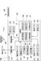
次に、図1から図3を参照して自律走行システム100について具体的に説明する。図1は、トラクタ1の全体的な構成を示す側面図である。図2は、トラクタ1の平面図である。図3は、自律走行システム100の制御系の主要な構成を示すブロック図である。 Next, the
図1に示すトラクタ1は、自律走行システム100で用いられ、無線通信端末46との間で無線通信を行うことにより操作される。トラクタ1は、圃場内を自律走行することが可能な走行機体(車体部)2を備える。走行機体2の後部には、例えば農作業を行うための作業機3が着脱可能に取り付けられている。 The
この作業機3としては、例えば、耕耘機、プラウ、施肥機、草刈機、播種機等の種々の作業機があり、これらの中から選択された作業機3が走行機体2に装着される。また、走行機体2は、装着された作業機3の高さ及び姿勢を変更可能に構成されている。 Examples of the
トラクタ1の構成について、図1及び図2を参照してより詳細に説明する。トラクタ1の走行機体2は、図1に示すように、その前部が左右1対の前輪(車輪)7,7で支持され、その後部が左右1対の後輪8,8で支持されている。 The configuration of the
走行機体2の前部にはボンネット9が配置されている。このボンネット9内には、トラクタ1の駆動源であるエンジン10及び燃料タンク(図略)が収容されている。このエンジン10は、例えばディーゼルエンジンにより構成することができるが、これに限るものではなく、例えばガソリンエンジンにより構成してもよい。また、駆動源としては、エンジンに加えて、又はこれに代えて、電気モータを使用してもよい。 A
ボンネット9の後方には、ユーザが搭乗するためのキャビン11が配置されている。このキャビン11の内部には、ユーザが操舵を行うためのステアリングハンドル(操舵具)12と、ユーザが着座可能な座席13と、各種の操作を行うための様々な操作具と、が主として設けられている。ただし、トラクタ1等の作業車両は、キャビン11を備えていてもよいし、キャビン11を備えていなくてもよい。 A
上記の操作具としては、図2に示すモニタ装置14、スロットルレバー15、主変速レバー27、複数の油圧操作レバー16、PTOスイッチ17、PTO変速レバー18、副変速レバー19、前後進切換レバー25、パーキングブレーキ26、作業機昇降スイッチ28等を例として挙げることができる。これらの操作装置は、座席13の近傍、又はステアリングハンドル12の近傍に配置されている。 2, a
モニタ装置14は、トラクタ1の様々な情報を表示可能に構成されている。スロットルレバー15は、エンジン10の回転速度を設定するための操作具である。主変速レバー27は、トラクタ1の走行速度を無段階で変更するための操作具である。油圧操作レバー16は、図略の油圧外部取出バルブを切換操作するための操作具である。PTOスイッチ17は、トランスミッション22の後端から突出した図略のPTO軸(動力取出軸)への動力の伝達/遮断を切換操作するための操作具である。即ち、PTOスイッチ17がON状態であるときPTO軸に動力が伝達されてPTO軸が回転し、作業機3が駆動される一方、PTOスイッチ17がOFF状態であるときPTO軸への動力が遮断されてPTO軸が回転せず、作業機3が停止される。PTO変速レバー18は、作業機3に入力される動力の変更操作を行うものであり、具体的にはPTO軸の回転速度の変速操作を行うための操作具である。副変速レバー19は、トランスミッション22内の走行副変速ギア機構の変速比を切り換えるための操作具である。前後進切換レバー25は、前進位置、中立位置、後進位置の間で切換可能に構成されている。前後進切換レバー25が前進位置に位置する場合、エンジン10の動力が後輪8に伝達されることでトラクタ1が前進する。前後進切換レバー25が中立位置に位置する場合、トラクタ1は前進も後進も行わない。前後進切換レバー25が後進位置に位置する場合、エンジン10の動力が後輪8に伝達されることでトラクタ1が後進する。パーキングブレーキ(制動操作具)26は、ユーザが手で操作して制動力を発生させる操作具であり、例えばトラクタ1をしばらく停車させる場合等に用いられる。作業機昇降スイッチ28は、走行機体2に装着された作業機3の高さを所定範囲内で昇降操作するための操作具である。 The
図1に示すように、走行機体2の下部には、トラクタ1のシャーシ20が設けられている。当該シャーシ20は、機体フレーム21、トランスミッション22、フロントアクスル23、及びリアアクスル24等から構成されている。 As shown in FIG. 1 , a
機体フレーム21は、トラクタ1の前部における支持部材であって、直接、又は防振部材等を介してエンジン10を支持している。トランスミッション22は、エンジン10からの動力を変化させてフロントアクスル23及びリアアクスル24に伝達する。フロントアクスル23は、トランスミッション22から入力された動力を前輪7に伝達するように構成されている。リアアクスル24は、トランスミッション22から入力された動力を後輪8に伝達するように構成されている。 The
図3に示すように、トラクタ1は、制御部4を備える。制御部4は公知のコンピュータとして構成されており、図示しないCPU等の演算装置、不揮発性メモリ等の記憶装置、及び入出力部等を備える。記憶装置には、各種のプログラム及びトラクタ1の制御に関するデータ等が記憶されている。演算装置は、各種のプログラムを記憶装置から読み出して実行することができる。上記のハードウェアとソフトウェアの協働により、制御部4を走行制御部4a、昇降制御部4b、作業制御部4c、角度判定部4d、位置判定部4e、及び位置算出部4fとして動作させることができる。なお、制御部4は、これら以外の制御(例えば撮影した画像の解析等)を行うこともできる。また、制御部4は、1つのコンピュータから構成されていてもよいし、複数のコンピュータから構成されていてもよい。 As shown in FIG. 3 , the
走行制御部4aは、トラクタ1の車速を制御する車速制御と、トラクタ1を操舵する操舵制御と、を行う。制御部4は、車速制御を行う場合、エンジン10の回転速度及びトランスミッション22の変速比の少なくとも一方を制御する。 The
具体的には、エンジン10には、当該エンジン10の回転速度を変更させる図略のアクチュエータを備えたガバナ装置41が設けられている。走行制御部4aは、ガバナ装置41を制御することで、エンジン10の回転速度を制御することができる。また、エンジン10には、エンジン10の燃焼室内に噴射(供給)するための燃料の噴射時期・噴射量を調整する燃料噴射装置45が付設されている。走行制御部4aは、燃料噴射装置45を制御することで、例えばエンジン10への燃料の供給を停止させ、エンジン10の駆動を停止させることができる。 Specifically, the
また、トランスミッション22には、例えば可動斜板式の油圧式無段変速装置である変速装置42が設けられている。走行制御部4aは、変速装置42の斜板の角度を図略のアクチュエータによって変更することで、トランスミッション22の変速比を変更する。以上の処理を行うことにより、トラクタ1が目標の車速に変更される。 The
走行制御部4aは、操舵制御を行う場合、ステアリングハンドル12の回動角度を制御する。具体的には、ステアリングハンドル12の回転軸(ステアリングシャフト)の中途部には、操舵アクチュエータ43が設けられている。この構成で、予め定められた経路をトラクタ1が走行する場合、制御部4は、当該経路に沿ってトラクタ1が走行するようにステアリングハンドル12の適切な回動角度を計算し、得られた回動角度となるように操舵アクチュエータ43を駆動し、ステアリングハンドル12の回動角度を制御する。 The
昇降制御部4bは、作業機3の昇降を制御する。具体的には、トラクタ1は、作業機3を走行機体2に連結している3点リンク機構の近傍に、油圧シリンダ等からなる昇降アクチュエータ44を備えている。昇降制御部4bは、昇降アクチュエータ44を駆動することで、作業機3を上昇させたり下降させたりすることができる。これにより、作業機3の高さを作業位置と退避位置の間で変更できる。作業位置は、退避位置よりも下方であり、作業機3による作業を行うための位置である。作業機3を用いた作業は圃場に対して一定の高さで行うことが好ましい場合もあるため、作業位置は、最下げ位置だけでなく、それよりも若干高い位置も含む。また、退避位置は、最上げ位置だけでなく、それよりも若干低い位置も含む。なお、昇降制御部4bは、角度判定部4d及び位置判定部4e等の判定結果に基づいて、圃場の出入口のスロープ又はその近傍で作業機3を昇降する(詳細は後述)。 The
作業制御部4cは、作業実行条件を満たすか否かに基づいて、PTOスイッチ17を制御することで、作業機3の駆動と停止を切り替える。また、作業制御部4cは、PTO変速機構等を制御することで、所定の条件に基づいて決定した回転速度でPTO軸を回転させる。 The
上述のような制御部4を備えるトラクタ1は、ユーザがキャビン11内に搭乗して各種操作をしなくとも、当該制御部4によりトラクタ1の各部(走行機体2、作業機3等)を制御して、圃場内を自律走行しながら自律作業を行うことができる。 The
次に、自律走行を行うために必要な情報を取得する構成について説明する。具体的には、本実施形態のトラクタ1は、図3等に示すように、無線通信用アンテナ48、慣性計測ユニット(IMU)61、測位用アンテナ6、距離検出センサ63、前方カメラ56、後方カメラ57、車速センサ53、及び舵角センサ52等を備える。 Next, a configuration for acquiring information necessary for autonomous travel will be described. Specifically, the
無線通信用アンテナ48は、ユーザが操作する無線通信端末46からの信号を受信したり、無線通信端末46への信号を送信したりするものである。図1に示すように、無線通信用アンテナ48は、トラクタ1のキャビン11が備えるルーフ5の上面に取り付けられている。無線通信用アンテナ48で受信した無線通信端末46からの信号は、図3に示す無線通信部40で信号処理された後、制御部4に入力される。また、制御部4等から無線通信端末46に送信する信号は、無線通信部40で信号処理された後、無線通信用アンテナ48から送信されて無線通信端末46で受信される。 The
慣性計測ユニット(角度センサ)61は、トラクタ1の走行機体2の姿勢や加速度等を特定することが可能なセンサユニットである。慣性計測ユニット61は、3つのジャイロセンサ(角速度センサ)と3つの加速度センサを備える。これにより、慣性計測ユニット61は、トラクタ1の走行機体2の姿勢変化の角速度(ロール角速度、ピッチ角速度、及びヨー角速度)、並びに、前後方向、左右方向、及び上下方向の加速度を特定できるようになっている。また、角速度を積分することにより、トラクタ1の姿勢(ロール角、ピッチ角、ヨー角)を特定できる。なお、本実施形態では、トラクタ1の前部が後部よりも上方になるように回転する方向をピッチ角の正と規定し、その逆方向をピッチ角の負と規定とする。 The inertial measurement unit (angle sensor) 61 is a sensor unit capable of identifying the attitude, acceleration, etc. of the traveling
測位用アンテナ6は、例えば衛星測位システム(GNSS)等の測位システムを構成する測位衛星からの信号を受信するものである。図1に示すように、測位用アンテナ6は、トラクタ1のキャビン11のルーフ5の上面に取り付けられている。測位用アンテナ6で受信された測位信号は、図3に示す位置検出部62に入力される。位置検出部62は、トラクタ1の走行機体2(厳密には、測位用アンテナ6)の位置を、例えば緯度・経度情報として算出し、検出する。当該位置検出部62が検出した位置は、制御部4に入力されて、自律走行に利用される。 The
なお、本実施形態ではGNSS-RTK法を利用した高精度の衛星測位システムが用いられているが、これに限るものではなく、高精度の位置座標が得られる限りにおいて他の測位システムを用いてもよい。例えば、相対測位方式(DGPS)、又は静止衛星型衛星航法補強システム(SBAS)を使用することが考えられる。 In this embodiment, a high-precision satellite positioning system using the GNSS-RTK method is used. good too. For example, relative positioning (DGPS) or geostationary satellite augmentation system (SBAS) could be used.
距離検出センサ63は、前方に送信波(電磁波)を照射するとともに、当該送信波が対象物で反射した反射波(電磁波)を受信する。距離検出センサ63は、送信波を送信してから反射波を受信するまでの時間に基づいて対象物までの距離を算出する。なお、反射波の解析は、距離検出センサ63とは離れた位置に配置された別の演算装置(例えば制御部4)が行っても良い。また、本実施形態では、電磁波を送受信して対象物までの距離を検出するが、超音波を送受信して対象物までの距離を検出してもよい。距離検出センサ63の検出結果に基づいて制御部4が障害物の存在を特定した場合、走行制御部4aは、トラクタ1を停止させたり、進行方向を変更させたりすることで、障害物との接触を防止する。なお、距離検出センサ63の検出結果は、後述の作業機下降制御にも用いられる。 The
前方カメラ56はトラクタ1の前方を撮影するものである。後方カメラ57はトラクタ1の後方を撮影するものである。前方カメラ56及び後方カメラ57はトラクタ1のルーフ5に取り付けられている。前方カメラ56及び後方カメラ57で撮影された動画データは、無線通信部40により、無線通信用アンテナ48から無線通信端末46に送信される。動画データを受信した無線通信端末46は、その内容をディスプレイに表示する。 The
上記の車速センサ53は、トラクタ1の車速を検出するものであり、例えば前輪7,7の間の車軸に設けられる。車速センサ53で得られた検出結果のデータは、制御部4へ出力される。なお、トラクタ1の車速は車速センサ53で検出せずに、測位用アンテナ6に基づいて所定距離におけるトラクタ1の移動時間に基づいて算出してもよい。舵角センサ52は、前輪7,7の舵角を検出するセンサである。本実施形態において、舵角センサ52は前輪7,7に設けられた図示しないキングピンに備えられている。舵角センサ52で得られた検出結果のデータは、制御部4へ出力される。なお、舵角センサ52をステアリングシャフトに備える構成としてもよい。 The
無線通信端末46は、タブレット端末、スマートフォン又はノートPC等である。無線通信端末46は、例えば、トラクタ1の自律走行に関する設定をユーザが行うために用いられる。また、無線通信端末46は、トラクタ1の自律走行中においてユーザが状況を確認したり、トラクタ1に対して指示を送信するために用いられたりする。 The
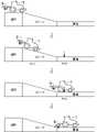
図4に示すように、トラクタ1が作業を行う圃場の近傍には、圃場に向かうトラクタ1が通行するための道路が設けられている。また、圃場は、道路等の圃場外部と比較して、低い位置に作成されている。従って、圃場と道路とは、スロープで接続されている。従って、このスロープは、圃場から道路(圃場外部)に近づくに連れて高さが高くなるように傾斜している。 As shown in FIG. 4, in the vicinity of the field where the
無線通信端末46には、上述した、圃場、スロープ、及び道路の位置及び形状が記憶されている。圃場、スロープ、及び圃場外部の位置及び形状は、トラクタ1を実際に走行させた際の測位用アンテナ6の位置の推移に基づいて作成されている。なお、トラクタ1を実際に走行させずに、例えば無線通信端末46に表示された地図上でユーザが範囲を指定することで、圃場、スロープ、及び道路の位置及び形状が作成されていてもよい。無線通信端末46に記憶されている情報と、位置検出部62が検出した位置と、に基づいて、トラクタ1が圃場、スロープ、及び道路の何れに位置しているかを特定できる。 The
また、無線通信端末46には、圃場においてトラクタ1を自律走行させるための経路が作成されて記憶されている。この経路には、例えば、圃場の作業領域内においてトラクタ1を直進させる直進経路と、直線経路同士を接続する旋回経路と、が含まれている。 Further, the
次に、図5及び図6を参照して、圃場から道路に向かう際に作業機3を自動的に上昇させる制御(以下、作業機上昇制御)について説明する。この制御は、作業機昇降制御装置80によって行われる。本実施形態の作業機昇降制御装置80は、慣性計測ユニット61と、位置検出部62と、距離検出センサ63と、作業制御部4cと、角度判定部4dと、位置判定部4eと、位置算出部4fと、を含む構成である。 Next, with reference to FIGS. 5 and 6, control for automatically raising the work implement 3 when going from the field to the road (hereinafter referred to as work implement lift control) will be described. This control is performed by the working machine lifting
初めに、制御部4は、作業機上昇制御が有効か否かを判定する(S101)。ユーザは、モニタ装置14又は無線通信端末46に所定の操作を行うことで、作業機上昇制御の有効及び無効を切替可能である。制御部4は、ユーザの設定に基づいて、ステップS101の判定を行う。 First, the
作業機上昇制御が有効である場合、制御部4(角度判定部4d)は、慣性計測ユニット61が検出したピッチ角が第1所定角度より大きいか否かを判定する(S102)。ここで、圃場を出て道路に向かう場合、トラクタ1がスロープを上ることとなるので、トラクタ1の前部が後部よりも高くなり、ピッチ角(正の値)が大きくなる。また、前輪7がスロープに到達した後からピッチ角は徐々に大きくなり、後輪8がスロープに到達した時点でピッチ角が最大値となる。従って、第1所定角度は、この最大値以下の数値が設定される。 When the work implement rise control is valid, the control section 4 (
ピッチ角が第1所定角度よりも大きい場合、制御部4(位置判定部4e)は、位置検出部62が検出したトラクタ1の位置からスロープまでの距離が閾値以下か否かを判定する(S103)。トラクタ1の位置は、測位用アンテナ6の位置なので1点である。スロープの位置は所定の範囲を示す。従って、例えば、トラクタ1の位置からスロープまでの最短距離が、「スロープまでの距離」に相当する。 When the pitch angle is greater than the first predetermined angle, the control unit 4 (
ステップS103では、トラクタ1の一部がスロープ上に位置しているか否かを判定することを目的としている。ここで、本実施形態ではステップS103の判定で用いるトラクタ1の位置は、厳密には測位用アンテナ6の位置であるため、トラクタ1の位置がスロープ上に位置していなくても、実際にはトラクタ1の前部がスロープ上に位置している可能性がある(図6においてトラクタ1の位置がP1であるときを参照)。なお、例えば測位用アンテナ6がトラクタ1の前部に取り付けられている場合、又は、位置検出部62の検出結果を前方にオフセットした値をトラクタ1の位置として取り扱っている場合は、トラクタ1の位置がスロープ上に位置しているか否かの判定を行ってもよい。 The purpose of step S103 is to determine whether part of the
次に、制御部4は、圃場端作業の設定が有効か否かを判定する(S104)。圃場端作業とは、圃場の端部(即ち、圃場とスロープの境界)まで作業機3による作業を行うための設定である。ユーザは、モニタ装置14又は無線通信端末46に所定の操作を行うことで、圃場端作業の設定の有効及び無効を切替可能である。制御部4は、ユーザの設定に基づいて、ステップS104の判定を行う。 Next, the
圃場端作業の設定が無効である場合、圃場の端部まで作業を行う必要はないため、制御部4(昇降制御部4b)は、作業機3を退避位置まで上昇する(S105)。 When the field edge work setting is disabled, there is no need to perform work to the edge of the field, so the control unit 4 (elevating
一方、圃場端作業の設定が有効である場合、制御部4(位置算出部4f)は、上昇開始位置を決定する(S106)。上昇開始位置とは、作業機3の上昇を開始する位置である。図6では、P2が上昇開始位置に相当する。上昇開始位置は、例えば、スロープの位置(スロープと圃場の境界位置)と、作業機3の車長方向の長さと、車速センサ53が検出した車速と、エンジン回転速度等と、に基づいて決定される。スロープの位置は、作業機3をスロープに衝突させないための上昇開始位置を算出するために用いられる。また、作業機3の車長方向の長さが長くなるに連れて、測位用アンテナ6から後方に離れた位置で作業が行われることになるため、上昇開始位置は圃場から離れた位置となる。車速及びエンジン回転速度が速くなるに連れて、油圧ポンプの出力を確保できるため、作業機3を短時間で上昇させることができる。従って、作業機3の上昇を開始してから作業機3がスロープに衝突しない高さまで上昇するまでに掛かる時間が短くなる。なお、車速が速い場合は、トラクタ1がスロープに近づくまでに掛かる時間が短くなる。以上を考慮して、作業機3がスロープに衝突しない範囲で、作業が行われる範囲を広くするための上昇開始位置が決定される。 On the other hand, when the field edge work setting is valid, the control unit 4 (the
そして、制御部4は、トラクタ1の位置が上昇開始位置に到達したか否かを判定しており(S107)、当該上昇開始位置に到達したと判定した場合、制御部4(昇降制御部4b)は、作業機3の上昇を開始する(S105、図6)。以上により、圃場の端部まで作業を行いつつ、作業機3がスロープに衝突することを防止できる。また、トラクタ1が道路に到達した後において、作業機3が道路の路面に衝突することも防止できる。 Then, the
このように、圃場端作業が有効な場合は、トラクタ1の位置が上昇開始位置に到達することが、第1位置条件に相当する。一方で、圃場端作業が無効な場合は、トラクタ1の位置からスロープの位置までの距離が閾値以下であることが、第1位置条件に相当する。なお、これらとは異なる第1位置条件が設定されていてもよい。 In this way, when the field edge work is effective, the
次に、図7及び図8を参照して、道路から圃場に向かう際に作業機3を自動的に下降させる制御(以下、作業機下降制御)について説明する。この制御も、作業機昇降制御装置80によって行われる。 Next, with reference to FIGS. 7 and 8, control for automatically lowering the work implement 3 when going from the road to the field (hereinafter referred to as work implement lowering control) will be described. This control is also performed by the working machine lifting
初めに、制御部4は、作業機下降制御が有効か否かを判定する(S201)。上記の作業機上昇制御と同様に、ユーザは、モニタ装置14又は無線通信端末46に所定の操作を行うことで、作業機下降制御の有効及び無効を切替可能である。制御部4は、ユーザの設定に基づいて、ステップS201の判定を行う。 First, the
作業機下降制御が有効である場合、制御部4(角度判定部4d)は、慣性計測ユニット61が検出したピッチ角が負で、絶対値が第2所定角度より大きいか否かを判定する(S202)。ここで、道路から圃場に向かう場合、トラクタ1がスロープを下ることとなるので、トラクタ1の前部が後部よりも低くなり、ピッチ角が負となる。また、前輪7がスロープに到達した後からピッチ角の絶対値は徐々に大きくなり、後輪8がスロープに到達した時点でピッチ角の絶対値が最大値となる。ここで、上記の作業機上昇制御では、トラクタ1がスロープが近接したタイミングで作業機3を上昇させることを目的とする。これに対し、作業機下降制御では、図8に示すように、トラクタ1が圃場に近接したタイミングで作業機3を下降させることを目的とする。従って、作業機下降制御では、トラクタ1の前輪のみがスロープ上に位置した状態を検出する必要はなく、例えば図8にP11で示すように、トラクタ1の全体がスロープ上に位置した状態を検出すればよい。そのため、第2所定角度は最大値に近い値としてもよい。つまり、第2所定角度は第1所定回度より大きくしてもよい。ただし、第1所定角度と第2所定角度が同じであってもよい。 When the work implement lowering control is valid, the control unit 4 (
ピッチ角が第2所定角度よりも大きい場合、制御部4(位置判定部4e)は、位置検出部62が検出したトラクタ1の位置がスロープ上であるか否かを判定する(S203)。上述のように、作業機下降制御ではトラクタ1が圃場に近づいたタイミングで作業機3を下降させることを目的としているため、トラクタ1の位置がスロープに近づいたことを検出する必要はない(ステップS103のような閾値は不要である)。従って、本実施形態では、トラクタ1がスロープ上の位置していることが、第2位置条件に相当する。ただし、ステップS203をステップS103と同様の処理にしてもよい。なお、これらとは異なる第2位置条件が設定されていてもよい。 When the pitch angle is larger than the second predetermined angle, the control section 4 (
ピッチ角及びトラクタ1の位置が上記の2つの条件を満たす場合、制御部4(位置算出部4f)は、下降開始位置を決定する(S204)。下降開始位置とは、作業機3の下降を開始する位置である。図8では、P12が下降開始位置に相当する。下降開始位置は、例えば、スロープの位置(スロープと圃場の境界位置)と、作業機3の車長方向の長さと、車速センサ53が検出した車速と、エンジン回転速度等と、に基づいて決定される。それぞれのデータの利用方法は、上昇開始位置の算出と同じである。また、本実施形態の下降開始位置の演算では、更に、距離検出センサ63が検出した距離が更に用いられる。スロープを走行しているトラクタ1にとっては、圃場は傾斜しているため反射波に基づいて圃場の端部までの距離を特定できる。これにより、圃場の端部までの距離を一層正確に検出できるため、より適切な下降開始位置を決定できる。なお、距離検出センサ63の検出結果を用いずに、トラクタ1の位置と、予め記憶されたスロープ位置(緯度・経度情報)と、に基づいて圃場の端部までの距離を算出してもよい。以上を考慮して、作業機3がスロープに衝突しない範囲で、作業機3ができる限り圃場の端部に近い位置で下降させるための下降開始位置が決定される。 When the pitch angle and the position of the
そして、制御部4は、トラクタ1の位置が下降開始位置に到達したか否かを判定しており(S205)、当該下降開始位置に到達したと判定した場合、制御部4(昇降制御部4b)は、作業機3の下降を開始する(S206、図8)。以上により、圃場の端部まで作業を行いつつ、作業機3がスロープに衝突することを防止できる。 Then, the
なお、作業機上昇制御で圃場端作業が有効である場合、又は、作業機下降制御において、制御部4(走行制御部4a)がトラクタ1を停止させたり、減速させたりしてもよい。これにより、圃場とスロープの境界間際まで作業を行うことができる。なお、この機能についても有効及び無効が切替可能であってもよい。 It should be noted that the control unit 4 (
次に、図9を参照して、トラクタ1が圃場の外部にある場合に行われる制御(下降禁止制御、自動最上げ制御)について説明する。 Next, with reference to FIG. 9, the control (descent prohibition control, automatic top-up control) performed when the
初めに、制御部4(位置判定部4e)は、位置検出部62が検出したトラクタ1の位置が圃場外部の道路上にあるか否かを判定する(S301)。上述したように、圃場外部の道路の位置は予め登録されて無線通信端末46等に記憶されている。 First, the control unit 4 (
次に、制御部4は、車速センサ53の検出結果等に基づいて、トラクタ1が走行中か否かを判定する(S302)。 Next, the
制御部4は、トラクタ1が圃場外部の道路に位置しており、かつ、トラクタ1が走行中である場合、下降禁止制御が有効か否かを判定する(S303)。下降禁止制御とは、トラクタ1が圃場外部を走行中である限り、たとえユーザが作業機3の下降を指示しても作業機3の下降を禁止する制御である。下降禁止制御を有効にすることで、ユーザの操作ミス等によって作業機3の下降が指示された場合でも作業機3が実際に下降しないため、作業機3の破損等を防止できる。他の制御と同様に、ユーザは、モニタ装置14又は無線通信端末46に所定の操作を行うことで、下降禁止制御の有効及び無効を切替可能である。制御部4は、ユーザの設定に基づいて、ステップS303の判定を行う。 When the
制御部4は、下降禁止制御が有効である場合、トラクタ1が圃場外部を走行中である限り、ユーザが作業機3の下降を指示しても作業機3の下降を禁止する(S304)。 When the descent prohibition control is valid, the
次に、制御部4は、下降禁止制御の有効/無効に関係なく、自動最上げ制御が有効か否かを判定する(S305)。自動最上げ制御とは、トラクタ1が圃場外部を走行中である限り、作業機3の高さを最も高くする制御である。自動最上げ制御を有効にすることで、作業機3が道路に接触することを一層確実に防止するとともに、ユーザが作業機3を上昇させる操作を忘れていた場合であっても作業機3を上昇させることができる。他の制御と同様に、ユーザは、モニタ装置14又は無線通信端末46に所定の操作を行うことで、自動最上げ制御の有効及び無効を切替可能である。なお、下降禁止制御と自動最上げ制御は独立して有効及び無効を切替可能である。制御部4は、ユーザの設定に基づいて、ステップS305の判定を行う。 Next, the
制御部4は、自動最上げ制御が有効である場合、作業機3の現在の高さが最上げ位置でない場合は作業機3を最上げ位置まで上昇させる(S306)。 When the automatic top-up control is valid, the
なお、上記の作業機上昇制御、作業機下降制御、下降禁止制御、及び自動最上げ制御は、作業機3毎に有効及び無効の設定を行うことができる。これにより、トラクタ1に装着する作業機3を変更した場合であっても、以前の設定を維持できる。また、作業機3の特性に応じて、予め推奨される設定が作業機3毎に登録されていてもよい。なお、作業機3毎の設定に代えて又は加えて、圃場毎にこれらの制御の有効及び無効を設定可能であってもよい。 It should be noted that the work implement lift control, work implement lowering control, lowering inhibition control, and automatic top-up control can be enabled or disabled for each work implement 3 . As a result, even when the work implement 3 attached to the
以上に説明したように、本実施形態の作業機昇降制御装置80は、慣性計測ユニット61と、位置検出部62と、角度判定部4dと、位置判定部4eと、昇降制御部4bと、を備える。慣性計測ユニット61は、トラクタ1の前部が上方に移動する回転方向を正とした当該トラクタ1のピッチ角を検出する。位置検出部62は、衛星測位システムを用いてトラクタ1の位置を検出する。角度判定部4dは、慣性計測ユニット61が検出したピッチ角が第1所定角度より大きいか否かを判定する。位置判定部4eは、位置検出部62が検出したトラクタ1の位置が、圃場よりも高い位置にある圃場外部と圃場とを接続するスロープの位置に対して第1位置条件を満たすか否かを判定する。昇降制御部4bは、ピッチ角が前記第1所定角度より大きいと角度判定部4dが判定し、かつ、トラクタ1の位置が第1位置条件を満たすと位置判定部が判定した場合に、作業機3を退避位置まで上昇させる。 As described above, the work implement
これにより、トラクタ1のピッチ角だけでなくトラクタ1の位置に基づいて、作業機3を退避位置まで上昇させるか否かを決定するため、例えば圃場の凹凸等でトラクタ1が傾斜しても作業機3が退避位置まで上昇しない。そのため、トラクタ1が確実にスロープを上がって圃場外部へ移動しているタイミングで、作業機3を退避位置まで上昇させることができる。 As a result, whether or not to raise the work implement 3 to the retracted position is determined based on not only the pitch angle of the
また、作業機昇降制御装置80は、車速センサ53と、位置算出部4fと、を備える。車速センサ53は、トラクタ1の車速を検出する。位置算出部4fは、ピッチ角が負で当該ピッチ角の絶対値が第2所定角度より大きいと角度判定部4dが判定し、かつ、トラクタ1の位置がスロープの位置に対して第2位置条件を満たすと位置判定部4eが判定した場合に、スロープの位置と、車速センサ53が検出した車速と、に基づいて、作業機3の下降開始位置を算出する。昇降制御部4bは、位置算出部4fが算出した下降開始位置で作業機3の下降を開始する。 In addition, the work implement lifting
これにより、スロープに作業機3が接触することを防止したり、圃場のうちスロープ側の端部に近い位置に作業機3を下降させたりすることができる。 As a result, the working
上記実施形態の作業機昇降制御装置80は、前方又は前下方の物体までの距離を検出する距離検出センサ63を備える。位置算出部4fは、スロープの位置と車速に加え、更に距離検出センサ63が検出した距離に基づいて、下降開始位置を算出する。 The work implement lifting
これにより、一層適切な下降開始位置を算出できるので、所望の位置に精度良く作業機3を下降させることができる。 As a result, a more appropriate descent start position can be calculated, so that the work implement 3 can be lowered to a desired position with high accuracy.
以上に本発明の好適な実施の形態を説明したが、上記の構成は例えば以下のように変更することができる。 Although the preferred embodiments of the present invention have been described above, the above configuration can be modified, for example, as follows.
角度判定部4d、位置判定部4e、及び位置算出部4fの少なくとも何れかが行う処理は、トラクタ1の制御部4ではなく、無線通信端末46で行ってもよい。 The processing performed by at least one of the
上記実施形態では、慣性計測ユニット61がトラクタ1のピッチ角を検出する構成であるが、少なくともピッチ角を検出可能であれば、他の構成のセンサであってもよい。 In the above-described embodiment, the inertial measurement unit 61 is configured to detect the pitch angle of the
上記実施形態では、距離検出センサ63の検出結果は下降開始位置の算出に用いられるが、それに代えて又は加えて、上昇開始位置の算出に用いられてもよい。 In the above-described embodiment, the detection result of the
上記実施形態では、圃場端作業、作業機下降制御、下段禁止制御、及び自動最上げ制御の有効及び無効が切替可能な構成であるが、作業機昇降制御装置80は、そもそもこれらの制御を行う機能を有していなくてもよい。 In the above-described embodiment, the field edge work, the work implement lowering control, the lower stage prohibition control, and the automatic top-up control can be switched between valid and invalid. It does not have to have a function.
上記実施形態では、上昇開始位置及び下降開始位置を算出するために複数のデータを用いる例を説明したが、これらのデータのうち少なくとも1つを省略してもよいし、別のデータを更に用いてもよい。 In the above embodiment, an example of using a plurality of data to calculate the ascending start position and descending start position has been described. may
1 トラクタ
4 制御部
4b 昇降制御部
61 慣性計測ユニット(角度センサ)
62 位置検出部
63 距離検出センサ
80 作業機昇降制御装置1
62
Claims (3)
Translated fromJapanese衛星測位システムを用いて前記作業車両の位置を検出する位置検出部と、
前記角度センサが検出した前記ピッチ角が第1所定角度より大きいか否かを判定する角度判定部と、
前記ピッチ角が前記第1所定角度より大きいと前記角度判定部が判定した場合、前記作業車両の現在位置から、圃場よりも高い位置にある圃場外部と圃場とを接続するスロープまでの距離が閾値以下であるかを判定する位置判定部と、
前記距離が閾値以下であると前記位置判定部が判定した場合、前記作業機を上昇させる上昇開始位置を決定する位置算出部と、
前記圃場から前記圃場外部に向かう際に、前記作業車両の位置が前記上昇開始位置に到達した場合に、前記作業機を退避位置まで上昇させる昇降制御部と、
を備えることを特徴とする作業機昇降制御装置。an angle sensor for detecting apitch angle of a work vehicle to which the work implement can be attached;
a position detection unit that detects the position of the work vehicle using a satellite positioning system;
an angle determination unit that determines whether the pitch angle detected by the angle sensor is greater than a first predetermined angle;
When the angle determination unit determines that the pitch angle is greater than the first predetermined angle, the distance from the current position of the work vehicle to the slope connecting the outside of the farm field and the farm field at a position higher than the field is a threshold value. a position determination unitthat determines whether
a position calculation unit that determines a lift start position for lifting the work implement when the position determination unit determines that the distance is equal to or less than a threshold;
an elevation control unit that raises the working machine to a retracted position whenthe position of the work vehicle reaches the elevation start position when heading from the agricultural field to the outside of the agricultural field ;
A work machine lifting control device comprising:
衛星測位システムを用いて前記作業車両の位置を検出する位置検出部と、
前記角度センサが検出した前記ピッチ角が第2所定角度より大きいか否かを判定する角度判定部と、
前記作業車両の現在位置が、圃場よりも高い位置にある圃場外部と圃場とを接続するスロープの位置にあるかを判定する位置判定部と、
前記圃場外部から前記圃場に向かう際に、前記ピッチ角が前記第2所定角度より大きいと前記角度判定部が判定し、かつ、前記作業車両の位置が前記スロープの位置にあると前記位置判定部が判定した場合に、前記作業機を下降させる下降開始位置を決定する位置算出部と、
を備えることを特徴とする作業機昇降制御装置。an angle sensor for detecting a pitch angle of a work vehicle to which the work implement can be attached;
a position detection unit that detects the position of the work vehicle using a satellite positioning system;
an angle determination unitthat determines whether the pitch angledetected by the angle sensor is greater than a second predetermined angle;
a position determination unit that determines whether the current position of the working vehicle is at the position of the slope that connects the outside of the farm field, which is higher than the farm field, and the farm field;
The position determination unit determines that the pitch angle is greater than the second predetermined angle when heading toward the farm field from outside the farm field, and that the work vehicle is positioned on the slope. a position calculation unit that determines a descent start position for descent of the work implement when it is determined that
A work machine lifting control devicecomprising :
前記作業車両が前記下降開始位置に到達した場合に、前記作業機の下降を開始する昇降制御部を備えることを特徴とする作業機昇降制御装置。The work machine lifting control device according to claim 2,
A working machine lifting control device, comprising: a lifting control section that starts lowering of the working machine when the working vehicle reaches the lowering start position .
Priority Applications (2)
| Application Number | Priority Date | Filing Date | Title |
|---|---|---|---|
| JP2018198202AJP7120878B2 (en) | 2018-10-22 | 2018-10-22 | Work equipment lifting control device |
| PCT/JP2019/036438WO2020084962A1 (en) | 2018-10-22 | 2019-09-18 | Operating machine elevation control device |
Applications Claiming Priority (1)
| Application Number | Priority Date | Filing Date | Title |
|---|---|---|---|
| JP2018198202AJP7120878B2 (en) | 2018-10-22 | 2018-10-22 | Work equipment lifting control device |
Publications (2)
| Publication Number | Publication Date |
|---|---|
| JP2020065451A JP2020065451A (en) | 2020-04-30 |
| JP7120878B2true JP7120878B2 (en) | 2022-08-17 |
Family
ID=70330975
Family Applications (1)
| Application Number | Title | Priority Date | Filing Date |
|---|---|---|---|
| JP2018198202AActiveJP7120878B2 (en) | 2018-10-22 | 2018-10-22 | Work equipment lifting control device |
Country Status (2)
| Country | Link |
|---|---|
| JP (1) | JP7120878B2 (en) |
| WO (1) | WO2020084962A1 (en) |
Families Citing this family (4)
| Publication number | Priority date | Publication date | Assignee | Title |
|---|---|---|---|---|
| WO2022038860A1 (en)* | 2020-08-20 | 2022-02-24 | 株式会社クボタ | Work machine |
| EP4108055B1 (en)* | 2021-06-22 | 2023-07-19 | Kubota Corporation | Agricultural machine |
| JP7322100B2 (en)* | 2021-06-22 | 2023-08-07 | 株式会社クボタ | Agricultural machines |
| JP7748622B2 (en)* | 2022-06-30 | 2025-10-03 | 井関農機株式会社 | Work vehicles |
Citations (5)
| Publication number | Priority date | Publication date | Assignee | Title |
|---|---|---|---|---|
| JP2012130264A (en) | 2010-12-20 | 2012-07-12 | Iseki & Co Ltd | Seedling transplanter |
| JP2016071426A (en) | 2014-09-26 | 2016-05-09 | 井関農機株式会社 | Operation auxiliary device of traveling working vehicle |
| US20160360697A1 (en) | 2013-09-03 | 2016-12-15 | Agco Corporation | System and method for automatically changing machine control state |
| JP2017176007A (en) | 2016-03-29 | 2017-10-05 | ヤンマー株式会社 | combine |
| JP6281436B2 (en) | 2014-07-29 | 2018-02-21 | 井関農機株式会社 | Work vehicle |
- 2018
- 2018-10-22JPJP2018198202Apatent/JP7120878B2/enactiveActive
- 2019
- 2019-09-18WOPCT/JP2019/036438patent/WO2020084962A1/ennot_activeCeased
Patent Citations (5)
| Publication number | Priority date | Publication date | Assignee | Title |
|---|---|---|---|---|
| JP2012130264A (en) | 2010-12-20 | 2012-07-12 | Iseki & Co Ltd | Seedling transplanter |
| US20160360697A1 (en) | 2013-09-03 | 2016-12-15 | Agco Corporation | System and method for automatically changing machine control state |
| JP6281436B2 (en) | 2014-07-29 | 2018-02-21 | 井関農機株式会社 | Work vehicle |
| JP2016071426A (en) | 2014-09-26 | 2016-05-09 | 井関農機株式会社 | Operation auxiliary device of traveling working vehicle |
| JP2017176007A (en) | 2016-03-29 | 2017-10-05 | ヤンマー株式会社 | combine |
Also Published As
| Publication number | Publication date |
|---|---|
| JP2020065451A (en) | 2020-04-30 |
| WO2020084962A1 (en) | 2020-04-30 |
Similar Documents
| Publication | Publication Date | Title |
|---|---|---|
| JP7583703B2 (en) | Autonomous driving system for work vehicles | |
| US10198010B2 (en) | Control device for work vehicle | |
| US10479354B2 (en) | Obstacle detection system for a work vehicle | |
| KR102107556B1 (en) | Parallel travel work system | |
| CN111580529B (en) | System | |
| JP7120878B2 (en) | Work equipment lifting control device | |
| KR102283927B1 (en) | Task vehicle control system | |
| CN110476527B (en) | Working vehicle | |
| CN111373894B (en) | Work vehicle | |
| JP2015201155A (en) | Coordinated travel work system | |
| JP2019165665A (en) | Automatic travel system for work vehicle | |
| JP6837449B2 (en) | Automatic driving system for work vehicles | |
| JP6078025B2 (en) | Parallel work system | |
| CN116507986A (en) | Automatic driving system, automatic driving method, and automatic driving program | |
| JP2020028243A (en) | Automatic running system for work vehicle | |
| JP6942666B2 (en) | Work vehicle | |
| JP7470843B2 (en) | Autonomous driving system and method | |
| US20250250779A1 (en) | Working vehicle remote operation assistance system and remote control apparatus | |
| JP7544778B2 (en) | Autonomous driving system for work vehicles | |
| CN114302640A (en) | Area registration system | |
| JP2023063476A (en) | Automated driving system for work vehicles | |
| JP2022085468A (en) | Work vehicle | |
| JP2024119075A (en) | Work vehicles | |
| WO2023119993A1 (en) | Field working machine | |
| JP2020178628A (en) | Autonomous travel work vehicle of field |
Legal Events
| Date | Code | Title | Description |
|---|---|---|---|
| A621 | Written request for application examination | Free format text:JAPANESE INTERMEDIATE CODE: A621 Effective date:20210112 | |
| A131 | Notification of reasons for refusal | Free format text:JAPANESE INTERMEDIATE CODE: A131 Effective date:20220301 | |
| A521 | Request for written amendment filed | Free format text:JAPANESE INTERMEDIATE CODE: A523 Effective date:20220428 | |
| TRDD | Decision of grant or rejection written | ||
| A01 | Written decision to grant a patent or to grant a registration (utility model) | Free format text:JAPANESE INTERMEDIATE CODE: A01 Effective date:20220726 | |
| A61 | First payment of annual fees (during grant procedure) | Free format text:JAPANESE INTERMEDIATE CODE: A61 Effective date:20220804 | |
| R150 | Certificate of patent or registration of utility model | Ref document number:7120878 Country of ref document:JP Free format text:JAPANESE INTERMEDIATE CODE: R150 |