Movatterモバイル変換


[0]ホーム

URL:


JP7119393B2 - Filling device, filling method and filling needle - Google Patents

Filling device, filling method and filling needle
Download PDF

Info

Publication number
JP7119393B2
JP7119393B2JP2018014151AJP2018014151AJP7119393B2JP 7119393 B2JP7119393 B2JP 7119393B2JP 2018014151 AJP2018014151 AJP 2018014151AJP 2018014151 AJP2018014151 AJP 2018014151AJP 7119393 B2JP7119393 B2JP 7119393B2
Authority
JP
Japan
Prior art keywords
filling
filling device
pair
jig
port
Prior art date
Legal status (The legal status is an assumption and is not a legal conclusion. Google has not performed a legal analysis and makes no representation as to the accuracy of the status listed.)
Active
Application number
JP2018014151A
Other languages
Japanese (ja)
Other versions
JP2019131231A (en
Inventor
将慶 籠田
洋 吉羽
孝之 池田
公一 辰巳
達郎 田所
麻衣 野澤
Current Assignee (The listed assignees may be inaccurate. Google has not performed a legal analysis and makes no representation or warranty as to the accuracy of the list.)
Dai Nippon Printing Co Ltd
Original Assignee
Dai Nippon Printing Co Ltd
Priority date (The priority date is an assumption and is not a legal conclusion. Google has not performed a legal analysis and makes no representation as to the accuracy of the date listed.)
Filing date
Publication date
Application filed by Dai Nippon Printing Co LtdfiledCriticalDai Nippon Printing Co Ltd
Priority to JP2018014151ApriorityCriticalpatent/JP7119393B2/en
Publication of JP2019131231ApublicationCriticalpatent/JP2019131231A/en
Priority to JP2022098769Aprioritypatent/JP7416132B2/en
Application grantedgrantedCritical
Publication of JP7119393B2publicationCriticalpatent/JP7119393B2/en
Activelegal-statusCriticalCurrent
Anticipated expirationlegal-statusCritical

Links

Images

Landscapes

Description

Translated fromJapanese

本開示の実施形態は、軟質容器に内容物を充填するための充填装置、充填方法及び充填用針に関する。 An embodiment of the present disclosure relates to a filling device, a filling method, and a filling needle for filling contents into a flexible container.

樹脂フィルムをヒートシールすることにより形成された軟質容器は、輸送効率の高さや環境負荷の少なさ等から、医薬品分野を始め、食品分野や化粧品分野等に広く使われている。このような軟質容器に内容物を充填する充填装置として、例えば特許文献1に記載されるものがある。この特許文献1には、軟質容器に設けられたノズル挿入空間の外周部分をその厚さ方向に引っ張る吸着パッドと、ノズル挿入空間の内部に挿入可能な充填ノズルとを備える充填装置が開示されている。ノズル挿入空間は、シール部に形成された開口部である(例えば、特許文献1の段落0024、0036、図2及び図6参照)。 Flexible containers formed by heat-sealing resin films are widely used in the fields of pharmaceuticals, foods, cosmetics, and the like because of their high transport efficiency and low environmental load. As a filling device for filling contents into such a soft container, there is one described in Patent Document 1, for example. This patent document 1 discloses a filling device that includes a suction pad that pulls the outer peripheral portion of a nozzle insertion space provided in a soft container in its thickness direction, and a filling nozzle that can be inserted into the nozzle insertion space. there is The nozzle insertion space is an opening formed in the seal portion (see, for example, paragraphs 0024 and 0036 of Patent Document 1, and FIGS. 2 and 6).

特開2017-24727号公報JP 2017-24727 A

内容物が充填される前の軟質容器では、内部に気体が入っていないので、樹脂フィルム同士が静電気等でくっついて密着する状態になっている。加えて、軟質容器が柔らかい樹脂フィルムにより形成されるので、容器全体が撓みやすい。このような状態で内容物を充填すると、充填された内容物が逆流する問題が生じやすい。 In the flexible container before it is filled with contents, since there is no gas inside, the resin films are in a state of sticking together due to static electricity or the like. In addition, since the flexible container is made of a soft resin film, the entire container is easily bent. If the contents are filled in such a state, the problem of backflow of the filled contents tends to occur.

本開示の実施形態は、上記の点に鑑みてなされたものであり、内容物の逆流を防止することができる充填装置、充填方法及び充填用針を提供することを目的とする。 The embodiments of the present disclosure have been made in view of the above points, and aim to provide a filling device, a filling method, and a filling needle that can prevent backflow of contents.

本開示の実施形態に係る充填装置は、ポートと少なくとも一対の側面を有する収容室とを備えた軟質容器に対し、前記ポートを介して前記収容室の内部に内容物を充填する充填装置であって、前記軟質容器を固定する固定治具、及び前記収容室の前記一対の側面を相対的に引き離す引き離し治具のうち、少なくとも一方を備えることを特徴としている。 A filling device according to an embodiment of the present disclosure is a filling device that fills a flexible container, which includes a port and a storage chamber having at least a pair of side surfaces, with contents inside the storage chamber through the port. and at least one of a fixing jig for fixing the soft container and a separating jig for relatively separating the pair of side surfaces of the storage chamber.

本開示の一実施形態に係る充填装置において、前記固定治具は、前記収容室の前記一対の側面に対応する一対の側壁部を有する箱状を呈し、各側壁部には、前記引き離し治具が通り抜け可能な開口部が設けられていることが好ましい。 In the filling device according to an embodiment of the present disclosure, the fixing jig has a box shape having a pair of side walls corresponding to the pair of side surfaces of the storage chamber, and the separation jig is attached to each side wall. It is preferable that an opening is provided through which the liquid can pass.

本開示の一実施形態に係る充填装置において、前記固定治具は、前記軟質容器の前記ポートを挟持する一対の挟持部材を有することが好ましい。 In the filling device according to an embodiment of the present disclosure, it is preferable that the fixing jig has a pair of clamping members that clamp the port of the soft container.

本開示の一実施形態に係る充填装置において、前記固定治具は、前記軟質容器に設けられた貫通孔と係合する係合部を有することが好ましい。 In the filling device according to an embodiment of the present disclosure, it is preferable that the fixing jig has an engaging portion that engages with a through-hole provided in the soft container.

また、本開示の一実施形態に係る充填装置において、前記固定治具は、前記軟質容器を挟持する少なくとも一対の挟持部材を有し、前記一対の挟持部材のうち一方には前記軟質容器に設けられた貫通孔に挿入可能な凸部が設けられ、他方には前記凸部と嵌合する凹部が設けられていることが好ましい。 Further, in the filling device according to an embodiment of the present disclosure, the fixing jig has at least a pair of clamping members that clamp the soft container, and one of the pair of clamping members is provided on the soft container. It is preferable that a convex portion that can be inserted into the through hole is provided, and a concave portion that engages with the convex portion is provided on the other side.

また、本開示の一実施形態に係る充填装置において、前記引き離し治具は、前記収容室の前記一対の側面を吸着する一対の吸着部を有することが好ましい。 Moreover, in the filling device according to an embodiment of the present disclosure, it is preferable that the separation jig has a pair of suction parts that suction the pair of side surfaces of the storage chamber.

更に、本開示の一実施形態に係る充填装置において、前記一対の吸着部は、中心位置がずれた状態で対向して配置されていることが好ましい。 Furthermore, in the filling device according to an embodiment of the present disclosure, it is preferable that the pair of suction units are arranged facing each other with their centers shifted.

更に、本開示の一実施形態に係る充填装置において、前記ポートが前記収容室の内部まで延設された場合において、前記一対の吸着部は、間に前記ポートが介在された状態で対向して配置されていることが好ましい。 Further, in the filling device according to the embodiment of the present disclosure, when the port extends to the interior of the storage chamber, the pair of suction portions face each other with the port interposed therebetween. is preferably arranged.

本開示の実施形態に係る充填方法は、上述の充填装置を用いた充填方法であって、前記充填装置が前記固定治具と前記引き離し治具とを備えるとき、前記固定治具に前記軟質容器を固定させる固定ステップと、前記引き離し治具を利用して前記収容室の前記一対の側面を相対的に引き離す引き離しステップと、前記ポートを介して前記収容室の内部に内容物を充填する充填ステップと、を含むことを特徴としている。 A filling method according to an embodiment of the present disclosure is a filling method using the above-described filling device, wherein when the filling device includes the fixing jig and the separating jig, the fixing jig is attached to the flexible container. a separating step of relatively separating the pair of side surfaces of the containing chamber using the separating jig; and a filling step of filling contents into the containing chamber through the port. and .

本開示の実施形態に係る充填用針は、内容物を充填するための充填用針であって、内部に軸方向に延在する内容物流路が設けられた針本体と、前記内容物流路と連通する内容物吐出口が設けられた針先部とを備え、前記針先部には、前記内容物流路を流れる内容物の流れ方向を前記軸方向に対して傾斜させるガイド壁部が設けられていることを特徴としている。 A filling needle according to an embodiment of the present disclosure is a filling needle for filling a content, and includes a needle body provided with a content channel extending in an axial direction inside, and the content channel. a needle tip portion provided with a communicating content ejection port, and the needle tip portion is provided with a guide wall portion that tilts the flow direction of the content flowing through the content flow path with respect to the axial direction. It is characterized by

本開示の一実施形態に係る充填用針において、前記ガイド壁部は、前記軸方向に対して15°~30°傾斜することが好ましい。 In the filling needle according to an embodiment of the present disclosure, it is preferable that the guide wall portion is inclined by 15° to 30° with respect to the axial direction.

本開示によれば、内容物の逆流を防止することができる。 According to the present disclosure, backflow of contents can be prevented.

軟質容器を示す正面図である。It is a front view which shows a soft container.第1実施形態に係る充填装置を示す斜視図である。1 is a perspective view showing a filling device according to a first embodiment; FIG.(a)は図2のX-X線に沿う断面図であり、(b)は引き離し状態を示す断面図である。(a) is a cross-sectional view taken along line XX of FIG. 2, and (b) is a cross-sectional view showing a detached state.充填装置の固定治具を示す斜視図である。It is a perspective view which shows the fixing jig of a filling apparatus.吸盤の中心位置がずれた状態を示す断面図である。FIG. 10 is a cross-sectional view showing a state in which the center position of the suction cup is displaced;充填装置の変形例を示す断面図である。It is a sectional view showing a modification of a filling device.第2実施形態に係る充填装置を示す斜視図である。It is a perspective view showing a filling device according to a second embodiment.図7のY-Y線に沿う断面図である。FIG. 8 is a cross-sectional view along line YY of FIG. 7;第3実施形態に係る充填装置を示す斜視図である。It is a perspective view showing a filling device according to a third embodiment.第4実施形態に係る充填装置を示す斜視図である。It is a perspective view showing a filling device according to a fourth embodiment.第5実施形態に係る充填装置を示す斜視図である。It is a perspective view which shows the filling apparatus which concerns on 5th Embodiment.第6実施形態に係る充填装置を示す斜視図である。It is a perspective view showing a filling device according to a sixth embodiment.第6実施形態に係る充填装置を示す分解斜視図である。FIG. 11 is an exploded perspective view showing a filling device according to a sixth embodiment;第7実施形態に係る充填装置を示す分解斜視図である。FIG. 11 is an exploded perspective view showing a filling device according to a seventh embodiment;第8実施形態に係る充填装置を示す分解斜視図である。FIG. 21 is an exploded perspective view showing a filling device according to an eighth embodiment;第8実施形態に係る充填装置を示す断面図である。FIG. 11 is a cross-sectional view showing a filling device according to an eighth embodiment;第9実施形態に係る充填装置を示す分解斜視図である。FIG. 21 is an exploded perspective view showing a filling device according to a ninth embodiment;第9実施形態に係る充填装置を示す模式断面図である。It is a schematic cross section showing a filling device according to a ninth embodiment.軟質容器の変形例を示す正面図である。It is a front view which shows the modification of a soft container.図19のZ-Z線に沿う断面図である。FIG. 20 is a cross-sectional view along line ZZ of FIG. 19;軟質容器の変形例を示す斜視図である。It is a perspective view which shows the modification of a soft container.粘着面を有する引き離し治具を説明するための図である。FIG. 4 is a diagram for explaining a separating jig having an adhesive surface;充填用針の構造を示す図である。FIG. 3 shows the structure of a filling needle;

以下、図面を参照して本発明に係る充填装置の実施形態を説明する。図面の説明において同一の要素には同一符号を付し、重複説明は省略する。 An embodiment of a filling device according to the present invention will be described below with reference to the drawings. In the description of the drawings, the same elements are denoted by the same reference numerals, and redundant description is omitted.

充填装置の説明に先たち、充填装置の適用対象である軟質容器の構造について説明する。図1は軟質容器を示す正面図である。図1に示すように、軟質容器10は、内容物を収納するための軟質バッグであり、例えば同じ大きさを有する矩形状の透明な樹脂フィルム(樹脂シートともいう)を2枚重ねて、内部に内容物を収容するための収容室12を形成するように、樹脂フィルムの周縁部同士を四辺に亘ってヒートシール(熱溶着ともいう)することによって形成されている。なお、ここでの軟質容器とは、容器全体が撓みやすく、それ自体では直立させることができない容器を意味する。 Before describing the filling apparatus, the structure of the flexible container to which the filling apparatus is applied will be described. FIG. 1 is a front view showing a soft container. As shown in FIG. 1, theflexible container 10 is a flexible bag for containing contents. It is formed by heat-sealing (also referred to as heat-sealing) the peripheral edge portions of the resin film to each other along the four sides so as to form astorage chamber 12 for storing the contents inside. The term "soft container" as used herein means a container whose entirety is easily bent and cannot stand upright by itself.

このため、軟質容器10の四辺にわたって、収容室12を取り囲むシール部11が形成されている。シール部11は、収容室12に対して上側シール部11a、下側シール部11b、左側シール部11c及び右側シール部11dに分けられている。上側シール部11a及び下側シール部11bは、他のシール部と比べて幅が比較的大きくなっている。収容室12は、一対の側面12L,12Rを有する。 For this reason, aseal portion 11 surrounding thestorage chamber 12 is formed along the four sides of theflexible container 10 . Theseal portion 11 is divided into anupper seal portion 11a, alower seal portion 11b, aleft seal portion 11c, and aright seal portion 11d with respect to thestorage chamber 12. As shown in FIG. The width of theupper seal portion 11a and thelower seal portion 11b is relatively large compared to the other seal portions. Theaccommodation chamber 12 has a pair ofside surfaces 12L and 12R.

上述の樹脂フィルムに用いられる材料としては、例えば高密度ポリエチレン(HDPE)、ポリメチルメタクリレート(PMMA)、ポリカーボネート(PC)、ポリスチレン(PS)、ポリエチレンテレフタレート(PET)、ポリプロプレン(PP)、ポリエチレン(PE)、ポリエチレンナフタレート(PEN)、シクロオレフィンポリマー(COP)、シクロオレフィンコポリマー(COC)、ポリアクリロニトリル(PAN)などが挙げられる。 Materials used for the above-mentioned resin film include, for example, high-density polyethylene (HDPE), polymethyl methacrylate (PMMA), polycarbonate (PC), polystyrene (PS), polyethylene terephthalate (PET), polypropylene (PP), polyethylene ( PE), polyethylene naphthalate (PEN), cycloolefin polymer (COP), cycloolefin copolymer (COC), polyacrylonitrile (PAN), and the like.

軟質容器10に充填される内容物としては、例えば食品関係の液体と医薬関係の液体が考えられる。具体的には、食品関係の液体としては、飲料や調味料が挙げられる。一方、医薬関係の液体としては、生理食塩水等の電解質輸液、ブドウ糖等の糖質注射液、血液製剤、抗生物質、抗体等の蛋白質性医薬品、低分子蛋白質、ホルモン等のペプチド性医薬品、核酸医薬品、細胞医薬品、各種感染症を予防するワクチン、ステロイド剤、インスリン、抗がん剤、蛋白質分解酵素阻害剤、鎮痛剤、解熱鎮痛消炎剤、麻酔剤、脂肪乳剤、血圧降下剤、血管拡張剤、ヘパリン塩化ナトリウムや乳酸カリウム等の電解質補正用注射液、ビタミン剤、造影剤等が挙げられる。 As the contents filled in theflexible container 10, for example, food-related liquids and medical-related liquids are conceivable. Specifically, food-related liquids include beverages and seasonings. On the other hand, medical-related liquids include electrolyte infusions such as physiological saline, carbohydrate injections such as glucose, blood products, antibiotics, protein drugs such as antibodies, peptide drugs such as low-molecular-weight proteins and hormones, and nucleic acids. Pharmaceuticals, cell medicines, vaccines to prevent various infectious diseases, steroids, insulin, anticancer agents, proteolytic enzyme inhibitors, analgesics, antipyretic analgesics, anti-inflammatory agents, anesthetics, lipid emulsions, antihypertensives, vasodilators , electrolyte correction injections such as heparin sodium chloride and potassium lactate, vitamin preparations, contrast agents, and the like.

図1に示すように、軟質容器10は、2つのポート13,14を備えている。ポート13,14は、収容室12を構成する樹脂フィルムよりも硬いプラスチック材料によって円筒状に形成され、上側シール部11aに取り付けられている。ポート13,14の一端部は、上側シール部11aを挿通して収容室12の内部と連通し、他端部は外方に突出し密閉栓15によって塞がれている。ポート13及びポート14は、軟質容器10の上下方向に延びる中心軸に対して左右対称に配置されている。ポート13及びポート14のうち、一方を内容物の充填用とし、他方を内容物の排出用としても良く、又は2種類の薬液を充填する場合にそれぞれの薬液充填用として使い分けても良い。 As shown in FIG. 1, theflexible container 10 has twoports 13,14. Theports 13 and 14 are formed in a cylindrical shape from a plastic material harder than the resin film forming thestorage chamber 12, and are attached to theupper seal portion 11a. One ends of theports 13 and 14 pass through theupper seal portion 11 a and communicate with the interior of thehousing chamber 12 , and the other ends protrude outward and are closed by asealing plug 15 . Theports 13 and 14 are arranged symmetrically with respect to the center axis extending in the vertical direction of theflexible container 10 . One of theports 13 and 14 may be used for filling contents and the other for discharging contents, or when two types of chemical solutions are to be filled, they may be used separately for filling each chemical solution.

密閉栓15は、ポート13,14の外周から突出するように、ポート13,14の外径よりも大きく形成されている。この密閉栓15は、収容室12の内部に内容物が充填された後にポート13,14の密閉に用いられるものであり、内容物が充填される前の状態ではポート13,14に取り付けられていないが、ポート13,14に対する密閉栓15の位置をより分かりやすくするために、全ての図面においては密閉栓15が取り付けられた状態を示す。Sealing plug 15 is formed larger than the outer diameter ofports 13 and 14 so as to protrude from the outer periphery ofports 13 and 14 . The sealingplug 15 is used to seal theports 13 and 14 after the content is filled into thestorage chamber 12, and is attached to theports 13 and 14 before the content is filled. However, in order to make the position of the sealingplug 15 relative to theports 13 and 14 easier to understand, all the drawings show the sealingplug 15 attached.

<第1実施形態>
図2は第1実施形態に係る充填装置を示す斜視図であり、図3(a)は図2のX-X線に沿う断面図であり、図3(b)は引き離し状態を示す断面図である。上述したようにポート13,14に対する密閉栓15の位置をより分かりやすくするために、図2においては密閉栓15がポート13,14に取り付けられた状態を示しているが、実際には内容物が充填されるまでは密閉栓15が取り付けられておらず、収容室12は吸盤3L,3Rの引張(後述する)で内部空間が拡げられて空気が自由に流入できる状態となっている。そして、内容物が充填された後に、密閉栓15をポート13,14に取り付けることでこれらのポート13,14を密閉する。
<First Embodiment>
2 is a perspective view showing the filling device according to the first embodiment, FIG. 3(a) is a cross-sectional view taken along line XX of FIG. 2, and FIG. 3(b) is a cross-sectional view showing a detached state. is. 2 shows the state where the sealingplug 15 is attached to theports 13 and 14 in order to make the position of the sealingplug 15 relative to theports 13 and 14 easier to understand as described above. The sealingplug 15 is not attached until thestorage chamber 12 is filled with air, and the internal space of thestorage chamber 12 is expanded by the tension of thesuction cups 3L and 3R (to be described later) so that air can flow freely. After the contents are filled, theports 13 and 14 are sealed by attaching the sealing plugs 15 to theports 13 and 14 .

本実施形態の充填装置1は、軟質容器10の収容室12の内部に内容物を充填するための装置であって、軟質容器10を固定する固定治具2と、収容室12の側面12L,12Rを互いに引き離す引き離し治具3と、収容室12の内部に内容物を充填する充填用針4とを備えている。なお、収容室12の側面12L,12Rは、軟質容器10の側面のうちシール部11を除いた部分であり、すなわち上側シール部11a、下側シール部11b、左側シール部11c及び右側シール部11dによって囲まれた部分である。 A filling device 1 of the present embodiment is a device for filling contents into astorage chamber 12 of aflexible container 10, and includes a fixingjig 2 for fixing theflexible container 10, aside surface 12L of thestorage chamber 12, Aseparation jig 3 for separating 12R from each other and a fillingneedle 4 for filling the inside of thestorage chamber 12 with contents are provided. The side surfaces 12L and 12R of thestorage chamber 12 are the side surfaces of theflexible container 10 excluding theseal portion 11, that is, theupper seal portion 11a, thelower seal portion 11b, theleft seal portion 11c and the right seal portion 11d. is the part surrounded by

図4は充填装置の固定治具を示す斜視図である。固定治具2は、軟質容器10をなるべく直立させた状態で収納できるように扁平箱状に形成されており、充填前の軟質容器10を収納可能、且つ内容物の充填によって軟質容器10が膨らんだ状態になっても取り外し可能な空間を有する。この固定治具2は、上方に開口しており、収容室12の側面12L,12Rに対応する一対の側壁部21,22を有する。側壁部21,22の中央位置には、収納される軟質容器10の側面12L,12Rの一部を露出させる開口部21a,22aが設けられている。この固定治具2は、金属製又は樹脂製である。そして、金属製の場合、軟質容器10へのダメージを避けるために、少なくとも軟質容器10に接する部分に柔らかい樹脂材料を用いることが好ましい。なお、開口部21a,22aは必ずしも側壁部21,22の中央位置に設ける必要がなく、少なくとも収容室12の側面12L,12Rを露出できる位置であれば中央位置以外に設けても良い。 FIG. 4 is a perspective view showing a fixing jig of the filling device. The fixingjig 2 is formed in a flat box shape so that thesoft container 10 can be stored in an upright state as much as possible. It has a removable space even if it is in a state. The fixingjig 2 is open upward and has a pair ofside walls 21 and 22 corresponding to theside walls 12L and 12R of thestorage chamber 12 .Openings 21a, 22a are provided at central positions of theside walls 21, 22 to expose part of the side surfaces 12L, 12R of thesoft container 10 to be accommodated. This fixingjig 2 is made of metal or resin. In the case of metal, it is preferable to use a soft resin material at least for the portion that contacts thesoft container 10 in order to avoid damage to thesoft container 10 . Theopenings 21a and 22a do not necessarily need to be provided at the central positions of theside walls 21 and 22, and may be provided at positions other than the central positions as long as the side surfaces 12L and 12R of thestorage chamber 12 can be exposed.

引き離し治具3は、一対の吸盤(吸着部)3L,3Rによって形成されている。吸盤3Lは、所定の厚さを有する円盤状を呈しており、固定治具2の側壁部21に設けられた開口部21aを通り抜けるように、開口部21aより小さく形成されている。同様に、吸盤3Rも、所定の厚さを有する円盤状を呈しており、固定治具2の側壁部22に設けられた開口部22aを通り抜けるように、開口部22aより小さく形成されている。 Theseparation jig 3 is formed by a pair of suction cups (suction portions) 3L and 3R. Thesuction cup 3L has a disk shape with a predetermined thickness and is formed smaller than theopening 21a so as to pass through theopening 21a provided in theside wall portion 21 of thefixture 2 . Similarly, thesuction cup 3R also has a disk shape with a predetermined thickness, and is formed smaller than theopening 22a so as to pass through theopening 22a provided in theside wall 22 of thefixture 2.

吸盤3Lと吸盤3Rとは、それぞれ樹脂材料で形成されており、中心位置が重なるよう(言い換えれば、中心位置が一致するように)に対向して配置されている。これらの吸盤3L,3Rは、図示しない駆動機構にそれぞれ取り付けられ、該駆動機構の駆動によって軟質容器10の側面12L,12Rに対して接近又は離間するようにされている。なお、ここでの中心位置は、吸盤の吸着面の法線方向からの平面視において、吸盤の吸着面の輪郭形状の中心の位置を指す。 The suction cups 3L and 3R are each made of a resin material, and are arranged facing each other so that their centers overlap (in other words, their centers match). Thesesuction cups 3L and 3R are attached to drive mechanisms (not shown), and driven by the drive mechanisms to approach or separate from the side surfaces 12L and 12R of thesoft container 10. As shown in FIG. The center position here refers to the position of the center of the outline shape of the suction surface of the suction cup in plan view from the normal direction of the suction surface of the suction cup.

このように構成された充填装置1を用いた充填方法は、固定治具2に軟質容器10を固定させる固定ステップと、引き離し治具3を利用して軟質容器10の側面12L,12Rを互いに引き離す引き離しステップと、軟質容器10のポート13,14を介して収容室12の内部に内容物を充填する充填ステップと、を含む。 A filling method using the filling device 1 configured as described above includes a fixing step of fixing thesoft container 10 to the fixingjig 2, and a separatingjig 3 to separate the side surfaces 12L and 12R of thesoft container 10 from each other. It includes a detachment step and a filling step of filling the interior of thestorage chamber 12 with contents through theports 13 and 14 of theflexible container 10 .

具体的には、固定ステップでは、軟質容器10をポート13,14が上に向くように固定治具2の開口から固定治具2の内部に挿入する。 Specifically, in the fixing step, thesoft container 10 is inserted into the fixingjig 2 through the opening of the fixingjig 2 so that theports 13 and 14 face upward.

固定ステップに次ぐ引き離しステップでは、上述の駆動機構を利用し、吸盤3Lを固定治具2の側壁部21に設けられた開口部21aを通り抜けて軟質容器10の側面12Lに押し付け、吸盤3Rを側壁部22に設けられた開口部22aを通り抜けて軟質容器10の側面12Rに押し付ける。ここで、吸盤3L,3Rは中心位置が重なるように対向して配置されるので、互いに押し合うことにより、吸盤3Lは側面12Lに吸着され、吸盤3Rは側面12Rに吸着される(図3(a)参照)。 In the separating step following the fixing step, the above-described drive mechanism is used to press thesuction cup 3L against theside surface 12L of theflexible container 10 through theopening 21a provided in theside wall portion 21 of the fixingjig 2, thereby removing thesuction cup 3R from the side wall. It passes through anopening 22a provided in theportion 22 and is pressed against theside surface 12R of theflexible container 10. As shown in FIG. Here, since thesuction cups 3L and 3R are arranged facing each other so that their central positions overlap each other, thesuction cups 3L and 3R are attracted to theside surface 12L and theside surface 12R, respectively, by pushing each other (FIG. 3 ( a) see).

続いて、上述の駆動機構を利用して吸盤3Lを軟質容器10の側面12Lから、吸盤3Rを側面12Rから離れるようにそれぞれ引っ張る。このとき、吸盤3Lと吸盤3Rとの位置を相対的にずらすように、横方向にスライドしてから或いはスライドしながらこれらの吸盤を引っ張ることが好ましい。このようにすれば、対向する吸盤3L,3R同士の押し合いによって吸盤3L,3Rの間に真空状態になったとしても、スライドすることで真空状態が解除されるので、吸盤3L及び吸盤3Rを容易に引き離すことができる。なお、スライドは、吸盤3L及び吸盤3Rのうち一方のみ実施しても良く、双方で実施しても良い。 Subsequently, using the drive mechanism described above, thesuction cup 3L is pulled away from theside surface 12L of thesoft container 10, and thesuction cup 3R is pulled away from theside surface 12R. At this time, it is preferable that thesuction cups 3L and 3R are pulled after or while sliding in the horizontal direction so that the positions of thesuction cups 3L and 3R are relatively shifted. In this way, even if a vacuum state is created between thesuckers 3L and 3R due to the pressing of the opposingsuckers 3L and 3R, the vacuum state is canceled by sliding, so that thesuckers 3L and 3R can be easily removed. can be pulled apart. Note that the slide may be performed by either one of thesuction cups 3L and thesuction cups 3R, or may be performed by both of them.

このとき、吸盤3Lが側面12L、吸盤3Rが側面12Rにそれぞれ吸着されるので、側面12L,12R同士が引き離れて収容室12の内部空間を拡げることができる(図3(b)参照)。なお、側面12L,12R同士を引き離す度合は、軟質容器10を構成する樹脂フィルムにダメージを与えない範囲内で設定されている。また、ここでは、上述の駆動機構に代えて手作業による吸盤3L,3Rの操作を実施しても良い。 At this time, thesuction cup 3L is attached to theside surface 12L and thesuction cup 3R is attached to theside surface 12R, so that the side surfaces 12L and 12R are pulled apart to expand the internal space of the storage chamber 12 (see FIG. 3B). The extent to which the side surfaces 12L and 12R are separated from each other is set within a range in which the resin film forming theflexible container 10 is not damaged. Further, here, instead of using the drive mechanism described above, thesuction cups 3L and 3R may be operated manually.

引き離しステップに次ぐ充填ステップでは、充填用針4をポート13,14から収容室12の内部の所定の深さまで挿入した状態で、該充填用針4を介して内容物を収容室12の内部に充填する。なお、内容物を充填する前に、充填用針4を介して収容室12の内部に空気等の気体を先に充填して良い。このようにすれば、上述の引き離しステップに加えて気体の充填で収容室12の内部空間を更に拡げることができる。 In the filling step following the separating step, the contents are introduced into thehousing chamber 12 through the fillingneedle 4 while the fillingneedle 4 is inserted from theports 13 and 14 to a predetermined depth inside thehousing chamber 12. to fill. It should be noted that before filling the contents, thestorage chamber 12 may be filled with a gas such as air through the fillingneedle 4 . In this way, the internal space of thestorage chamber 12 can be further expanded by filling with gas in addition to the above-described separating step.

充填ステップ終了後、充填用針4を引き抜いた後に、密閉栓15を使ってポート13,14を密閉する。続いて、吸盤3L,3Rを側面12L,12Rから取り外し、更に内容物充填済みの軟質容器10を固定治具2から取り外す。 After the filling step is completed, the sealingplug 15 is used to seal theports 13, 14 after the fillingneedle 4 has been withdrawn. Subsequently, thesuction cups 3L, 3R are removed from the side surfaces 12L, 12R, and the filledflexible container 10 is removed from the fixingjig 2.

本実施形態において、密閉栓15がポート13,14の外周から突出して形成された軟質容器10を挙げて説明するが、軟質容器10は必ずしも密閉栓15を有する必要がない。そして、密閉栓15を有さない軟質容器におけるポート13,14の密閉方法としては、例えばポート13,14を長く形成して、該ポート13,14の先端部を潰してヒートシールすることにより密閉する方法、ポート13,14の内部に栓を入れて密閉する方法、ポート13,14の端部をキャップ等で密閉する方法等が挙げられる。 In this embodiment, theflexible container 10 in which the sealing plugs 15 protrude from the outer peripheries of theports 13 and 14 will be described, but theflexible container 10 does not necessarily have the sealing plugs 15 . As a method for sealing theports 13 and 14 in a soft container that does not have the sealingplug 15, for example, theports 13 and 14 are formed long, and the tips of theports 13 and 14 are crushed and heat-sealed. a method of sealing theports 13 and 14 with plugs, a method of sealing the ends of theports 13 and 14 with caps or the like.

本実施形態の充填装置1では、軟質容器10を固定するための固定治具2を備えるので、軟質容器10を固定治具2に固定させることで、充填作業をよりスムーズに行うことができるとともに、撓みでポートの位置ずれや充填用針の位置ずれに起因した充填ミスの発生及び内容物漏れの発生を防止することができる。加えて、引き離し治具を用いて軟質容器10の側面12L,12R同士を引き離し、軟質容器10の収容室12の内部空間を拡げることで、充填される内容物がスムーズに収容室12の内部に充填され、内容物の逆流を防止することができる。 Since the filling device 1 of the present embodiment is provided with the fixingjig 2 for fixing thesoft container 10, by fixing thesoft container 10 to the fixingjig 2, the filling operation can be performed more smoothly. In addition, it is possible to prevent the occurrence of filling errors and content leakage due to misalignment of the port and the misalignment of the filling needle due to bending. In addition, by separating the side surfaces 12L and 12R of theflexible container 10 using a separating jig to expand the internal space of thestorage chamber 12 of theflexible container 10, the contents to be filled smoothly enter thestorage chamber 12. It is filled and can prevent backflow of contents.

また、引き離し治具3を用いて軟質容器10の側面12L,12R同士を引き離し、収容室12の内部空間を拡げることにより、充填用針4をポート13,14から収容室12の内部に挿入する際に、充填用針4が樹脂フィルムとの接触を抑制することができる。その結果、充填用針4と樹脂フィルムとの接触に起因する樹脂フィルムへのダメージ、接触による粉塵や異物の発生等を抑制することができる。しかも、この場合、充填用針4を樹脂フィルムに接触せずに収容室12の内部の深い位置まで挿入することができるので、充填時の泡立ちの発生を抑制する効果も期待できる。 In addition, thesides 12L and 12R of thesoft container 10 are separated from each other by using theseparation jig 3 to expand the internal space of thestorage chamber 12, thereby inserting the fillingneedle 4 into thestorage chamber 12 through theports 13 and 14. At this time, the fillingneedle 4 can be prevented from coming into contact with the resin film. As a result, it is possible to suppress damage to the resin film due to contact between the fillingneedle 4 and the resin film, and generation of dust and foreign matter due to contact. Moreover, in this case, since the fillingneedle 4 can be inserted to a deep position inside thestorage chamber 12 without contacting the resin film, an effect of suppressing foaming during filling can be expected.

なお、本実施形態では、吸盤3Lと吸盤3Rとは中心位置が重なるように対向して配置されるため、吸盤3L,3R同士の押し合いによって吸盤3L,3Rの間に真空状態になりやすい。その結果、吸盤3L,3R同士がくっつきやすいので、吸盤で軟質容器10の側面12L,12Rを引き離す際に引き離し難くなる可能性がある。そこで、例えば図5に示すように、吸盤3L及び吸盤3Rを中心位置がずれた状態で対向して配置させることで、吸盤3L,3Rの間に真空状態の発生を防止し、吸盤で軟質容器10の側面12L,12Rを引き離しやすくなる。吸盤3Lと吸盤3Rとの中心位置をずらすときに、上下方向、左右方向、或いは斜め方向に沿って行っても良い。 In this embodiment, since thesuction cups 3L and 3R are arranged facing each other so that their centers overlap each other, thesuction cups 3L and 3R are likely to be pressed against each other to create a vacuum state between thesuction cups 3L and 3R. As a result, since thesuction cups 3L and 3R are likely to stick to each other, it may be difficult to separate the side surfaces 12L and 12R of thesoft container 10 with the suction cups. Therefore, for example, as shown in FIG. 5, by arranging thesuction cups 3L and thesuction cups 3R facing each other with their centers shifted, the occurrence of a vacuum state between thesuction cups 3L and 3R can be prevented, and the suction cups can hold the soft container. The side surfaces 12L and 12R of 10 can be easily pulled apart. When shifting the central position of thesuction cup 3L and thesuction cup 3R, the displacement may be performed along the vertical direction, the horizontal direction, or the oblique direction.

一方、吸盤3Lと吸盤3Rとの中心位置を大きくずらすと、対向する吸盤同士の押し合う力が小さくなるので、吸盤3L,3Rと軟質容器10の側面12L,12Rとの吸着ができなくなる可能性がある。吸盤同士の押し合いによる吸着の実現及び軟質容器10の側面12L,12Rの引き離し易さを両立させるには、吸盤3L,3Rが円形状の場合、吸盤3L,3R同士の中心位置の間隔は吸盤3L,3Rの半径より小さいことが好ましい。一方、円形状以外の場合、吸盤3L,3R同士を中心位置が重なるように対向して配置した状態における任意に選択した重なり長さをXとしたとき、吸盤3L,3R同士の中心位置の間隔はX/2よりも小さいことが好ましい。 On the other hand, if the center positions of thesuction cups 3L and 3R are largely displaced, the pressing force between the opposing suction cups becomes small, so there is a possibility that thesuction cups 3L, 3R and the side surfaces 12L, 12R of thesoft container 10 cannot be adsorbed. There is If thesuction cups 3L and 3R are circular, the distance between the center positions of thesuction cups 3L and 3R should be equal to the distance between the centers of thesuction cups 3L and 3R in order to achieve both the suction by pressing the suction cups against each other and the ease of separating the side surfaces 12L and 12R of thesoft container 10. , 3R. On the other hand, when thesuction cups 3L and 3R are arranged to face each other so that the center positions of thesuction cups 3L and 3R are overlapped with each other, X is the overlapping length selected arbitrarily. is preferably less than X/2.

また、本実施形態の充填装置1について、様々な変形例が考えられる。例えば図6(a)に示す変形例では、引き離し治具3は吸盤3L及び吸盤3Rをそれぞれ2つずつ有する。ここで、吸盤3L,3Rの数はそれぞれ3つ以上であっても良い。更に、側面12Lを吸着する吸盤3Lの数と側面12Rを吸着する吸盤3Rの数とは、異なっても良い。このように複数の吸盤を用いた場合、吸盤のサイズを小さくすることができるので、特に軟質容器10の側面12L,12Rにラベルやシール等が貼られた場合に好適である。例えばラベルやシールに触れないようにラベルやシールのない場所に複数の吸盤3L,3Rを配置することにより、側面12L,12Rを吸着する力を確保しつつ、吸盤の吸着によるラベルやシールの汚れの発生を防止することができる。 Moreover, various modifications are conceivable for the filling device 1 of the present embodiment. For example, in the modification shown in FIG. 6A, theseparation jig 3 has twosuction cups 3L and twosuction cups 3R. Here, the number ofsuction cups 3L and 3R may each be three or more. Furthermore, the number ofsuction cups 3L for sucking theside surface 12L and the number ofsuction cups 3R for sucking theside surface 12R may be different. When a plurality of suction cups are used in this manner, the size of the suction cups can be reduced. For example, by arranging a plurality ofsuction cups 3L and 3R in places where there are no labels or stickers so as not to touch the labels or stickers, the force of sucking the side surfaces 12L and 12R is ensured, and the labels and stickers become dirty due to the adsorption of the suction cups. can be prevented from occurring.

また、図6(b)に示す変形例では、引き離し治具3は吸盤3Rのみを有する。この場合には、側壁部21に開口部21aを設けなくても良い。なお、ここでは、引き離し治具3は吸盤3Lのみを有して良い。また、吸盤の形状は、円形のほか、楕円形、三角形を含む多角形であっても良い。 Further, in the modification shown in FIG. 6B, theseparation jig 3 has only thesuction cups 3R. In this case, theside wall portion 21 does not need to be provided with theopening portion 21a. Here, theseparation jig 3 may have only thesuction cups 3L. Also, the shape of the suction cup may be circular, elliptical, or polygonal including triangular.

また、本実施形態の引き離し治具3としては、吸盤のほかに、吸着部とホースを介して吸着部に接続されるポンプやシリンジとを有するものであっても良い。この場合、ポンプやシリンジで吸着部と軟質容器10の側面12L,12Rとの間の空気を抜くことにより側面12L,12Rを吸着でき、更に吸着部と軟質容器10の側面12L,12Rとの間の空気を送ることにより吸着部を側面12L,12Rから簡単に外すことができる。 Further, the separatingjig 3 of the present embodiment may have a pump or a syringe connected to the suction part through a suction part and a hose, in addition to the suction cup. In this case, the side surfaces 12L and 12R can be adsorbed by removing the air between the adsorption portion and the side surfaces 12L and 12R of thesoft container 10 using a pump or syringe, and furthermore, the adsorption portion and the side surfaces 12L and 12R of thesoft container 10 can be sucked. of air can be easily removed from the side surfaces 12L and 12R.

更に、本実施形態の引き離し治具3としては、吸盤のほかに、粘着面を有するものであっても良い。例えば、引き離し治具3は粘着面を有する場合、粘着面を介して軟質容器10の側面12L,12Rに取り付けることができる。粘着面を外せば側面12L,12Rから取り外すことができる。 Furthermore, the separatingjig 3 of this embodiment may have an adhesive surface in addition to the suction cup. For example, if the separatingjig 3 has an adhesive surface, it can be attached to the side surfaces 12L and 12R of theflexible container 10 via the adhesive surface. It can be removed from the side surfaces 12L and 12R by removing the adhesive surface.

このような粘着面を有する引き離し治具は、少ない力で軟質容器10の側面12L,12R同士を引き離すために、粘着面が円形、楕円形、三角形を含む多角形であることが好ましい。一方、粘着面を有する引き離し治具の場合は、形状を柔軟に変えることができるので、特に軟質容器10の側面12L,12Rにラベルやシール等が貼られた場合に好適である。 In order to separate thesides 12L and 12R of theflexible container 10 with less force, the separating jig having such an adhesive surface preferably has a circular, elliptical, or polygonal adhesive surface including a triangle. On the other hand, a separating jig having an adhesive surface can flexibly change its shape, and is particularly suitable when labels, seals, etc. are attached to the side surfaces 12L and 12R of theflexible container 10. FIG.

例えば図22に示すように、軟質容器10の側面12L,12Rに内容物等の情報が印字されたラベル55及びラベル56が上下方向に離れて貼り付けられている。この場合、円形、楕円形又は多角形の引き離し治具3を用いると、引き離し治具3がラベル55,56の部分に触れ、印字部分を汚す可能性がある。そこで、ラベル55とラベル56との間の隙間形状に合わせた粘着面を有する引き離し治具3を用いることで、側面12L,12R同士を引き離す力を確保しつつ、ラベル55,56に触れないので、ラベル55,56の汚れ発生を防止できる。 For example, as shown in FIG. 22, alabel 55 and alabel 56 on which information such as contents is printed are attached to the side surfaces 12L and 12R of theflexible container 10 vertically separated from each other. In this case, if a circular, elliptical, orpolygonal separation jig 3 is used, theseparation jig 3 may come into contact with thelabels 55 and 56 and stain the printed portion. Therefore, by using the separatingjig 3 having an adhesive surface that matches the shape of the gap between thelabels 55 and 56, thelabels 55 and 56 are not touched while securing the force separating the side surfaces 12L and 12R. , contamination of thelabels 55 and 56 can be prevented.

<第2実施形態>
図7は第2実施形態に係る充填装置を示す斜視図であり、図8は図7のY-Y線に沿う断面図である。本実施形態の充填装置1Aは、固定治具2Aの構造において上述の第1実施形態と異なるが、その他の構造は第1実施形態と同様である。
<Second embodiment>
FIG. 7 is a perspective view showing a filling device according to the second embodiment, and FIG. 8 is a cross-sectional view taken along line YY of FIG. A fillingapparatus 1A of this embodiment differs from the above-described first embodiment in the structure of a fixingjig 2A, but the rest of the structure is the same as that of the first embodiment.

図7に示すように、本実施形態に係る充填装置1Aの適用対象である軟質容器10Aにおいて、上側シール部11aには貫通孔16が1つ設けられている。貫通孔16は、円形状を呈しており、軟質容器10Aの上下方向に延びる中心軸に位置し、言い換えれば、ポート13とポート14との中間位置に配置されている。 As shown in FIG. 7, in asoft container 10A to which thefilling apparatus 1A according to this embodiment is applied, one throughhole 16 is provided in theupper seal portion 11a. The through-hole 16 has a circular shape and is positioned on the center axis extending in the vertical direction of thesoft container 10A.

一方、該軟質容器10Aを固定する固定治具2Aは、平板状の基台23と、該基台23に立設された2本の支柱24,24と、支柱24,24の間に架設されて基台23と平行する上側横梁27及び下側横梁28とを有する。上側横梁27の中央位置には、軟質容器10に設けられた貫通孔16と係合可能な係合部26が配置されている。係合部26は、金属又は樹脂材料によりフック状に形成され、接着等で上側横梁27に固定されている。そして、軟質容器10Aは、その貫通孔16と固定治具2Aの係合部26との係合によって、固定治具2Aに吊持された状態で固定されている。 On the other hand, a fixingjig 2A for fixing thesoft container 10A comprises a flat plate-like base 23, twosupports 24, 24 erected on thebase 23, and a fixingjig 2A constructed between thesupports 24, 24. It has anupper cross-beam 27 and alower cross-beam 28 parallel to thebase 23 . An engagingportion 26 that can be engaged with the throughhole 16 provided in thesoft container 10 is arranged at the central position of theupper lateral beam 27 . The engagingportion 26 is formed in a hook shape from a metal or resin material and fixed to theupper lateral beam 27 by adhesion or the like. Theflexible container 10A is fixed in a state of being suspended by the fixingjig 2A by engaging the throughhole 16 with the engagingportion 26 of the fixingjig 2A.

このように構成された充填装置1Aを用いた充填方法は、上述の第1実施形態と同様に、固定治具2Aに軟質容器10Aを固定させる固定ステップと、引き離し治具3を利用して軟質容器10Aの側面12L,12Rを互いに引き離す引き離しステップと、軟質容器10Aのポート13,14を介して収容室12の内部に内容物を充填する充填ステップと、を含む。固定ステップは、貫通孔16を固定治具2Aの係合部26と係合させる点において、上述した第1実施形態の固定ステップと相違しているが、引き離しステップ及び充填ステップ等は、第1実施形態と同様のため、その説明を省略する。 The filling method using thefilling device 1A configured in this manner includes a fixing step of fixing thesoft container 10A to the fixingjig 2A and a soft container using theseparation jig 3, as in the above-described first embodiment. It includes a separating step of separating thesides 12L and 12R of thecontainer 10A from each other, and a filling step of filling the inside of the containingchamber 12 with the contents through theports 13 and 14 of theflexible container 10A. The fixing step is different from the fixing step of the above-described first embodiment in that the throughhole 16 is engaged with the engagingportion 26 of the fixingjig 2A. Since it is the same as the embodiment, its description is omitted.

本実施形態の充填装置1Aによれば、上述の第1実施形態と同様な作用効果を得られる。また、本実施形態において、係合部26がフック状である例を説明したが、係合部は軟質容器10Aの貫通孔16と係合できるものであれば、フック状以外の形状であっても良く、例えば棒状であっても良い。また、軟質容器10Aの貫通孔16の形状は円形のほか、楕円形、三角形等の多角形であっても良い。 According to thefilling device 1A of this embodiment, the same effects as those of the above-described first embodiment can be obtained. Further, in the present embodiment, an example in which the engagingportion 26 has a hook shape has been described, but the engaging portion may have any shape other than the hook shape as long as it can engage with the throughhole 16 of thesoft container 10A. Also, for example, it may be rod-shaped. Moreover, the shape of the through-hole 16 of thesoft container 10A may be circular, or polygonal such as elliptical or triangular.

<第3実施形態>
図9は第3実施形態に係る充填装置を示す斜視図である。本実施形態の充填装置1Bは、固定治具2Bに配置された係合部26の数及び位置において、上述の第2実施形態と異なるが、その他の構造は第2実施形態と同様である。
<Third Embodiment>
FIG. 9 is a perspective view showing a filling device according to the third embodiment. The fillingdevice 1B of this embodiment differs from the above-described second embodiment in the number and positions of the engagingportions 26 arranged on the fixingjig 2B, but the rest of the structure is the same as that of the second embodiment.

具体的には、軟質容器10Bにおいて、上側シール部11aと下側シール部11bには貫通孔16が1つずつ設けられている。これらの貫通孔16は、略対角線上に配置されている。なお、上側シール部11aに設けられた貫通孔16は、ポート13及びポート14のうち内容物充填用のポートに近い位置に配置されることが好ましい。このようにすれば、後に充填用針4をポートから収容室12の内部に挿入する際に、挿入作業をよりスムーズに行える。 Specifically, in theflexible container 10B, one throughhole 16 is provided in each of theupper seal portion 11a and thelower seal portion 11b. These throughholes 16 are arranged substantially diagonally. The through-hole 16 provided in theupper seal portion 11a is preferably arranged at a position closer to the port for content filling, out of theports 13 and 14. As shown in FIG. In this way, when inserting the fillingneedle 4 from the port into thestorage chamber 12 later, the insertion work can be performed more smoothly.

一方、該軟質容器10Bを固定する固定治具2Bにおいて、軟質容器10Bの2つの貫通孔16の位置に合わせて、2本の支柱24,24のうち一方の支柱24の上部に係合部26、他方の支柱24の下部に係合部26がそれぞれ配置されている。そして、軟質容器10Bは、その貫通孔16と固定治具2Bの係合部26との係合によって、固定治具2Bに吊持された状態で固定されている。 On the other hand, in the fixingjig 2B for fixing thesoft container 10B, an engagingportion 26 is attached to the top of one of the twoposts 24, 24 in alignment with the positions of the two throughholes 16 of the soft container 10B. , and the engagingportions 26 are arranged at the lower portions of theother supports 24, respectively. Theflexible container 10B is fixed in a state of being suspended by the fixingjig 2B by engaging the throughhole 16 with the engagingportion 26 of the fixingjig 2B.

本実施形態の充填装置1Bによれば、上述の第2実施形態と同様な作用効果を得られるほか、上下方向に2箇所に亘って軟質容器10Bを固定するので、第2実施形態と比べて軟質容器の10Bをより安定した状態で固定することができる。 According to thefilling device 1B of the present embodiment, in addition to obtaining the same effects as those of the above-described second embodiment, theflexible container 10B is fixed at two points in the vertical direction, so compared with the second embodiment, Thesoft container 10B can be fixed in a more stable state.

<第4実施形態>
図10は第4実施形態に係る充填装置を示す斜視図である。本実施形態の充填装置1Cは、固定治具2Cに配置された係合部26の数及び位置において、上述の第2実施形態と異なるが、その他の構造は第2実施形態と同様である。
<Fourth Embodiment>
FIG. 10 is a perspective view showing a filling device according to the fourth embodiment. The fillingdevice 1C of this embodiment differs from the above-described second embodiment in the number and positions of the engagingportions 26 arranged on the fixingjig 2C, but the rest of the structure is the same as that of the second embodiment.

具体的には、軟質容器10Cにおいて、上側シール部11aの左右両端部には貫通孔16が1つずつ設けられ、更に、下側シール部11bの中央位置には貫通孔16が1つ設けられている。該軟質容器10Cを固定する固定治具2Cにおいて、軟質容器10Cの3つの貫通孔16の位置に合わせて、2本の支柱24,24の上部に係合部26が1つずつ、下側横梁28の中央位置に係合部26が1つ配置されている。そして、軟質容器10Cは、その貫通孔16と固定治具2Cの係合部26との係合によって、固定治具2Cに吊持された状態で固定されている。 Specifically, in theflexible container 10C, one throughhole 16 is provided at each of the left and right ends of theupper seal portion 11a, and one throughhole 16 is provided at the center position of thelower seal portion 11b. ing. In the fixingjig 2C for fixing thesoft container 10C, one engagingportion 26 is provided on each of the twoposts 24, 24 in alignment with the positions of the three throughholes 16 of thesoft container 10C, and the lower lateral beam One engagingportion 26 is arranged at the central position of 28 . Theflexible container 10C is fixed in a state of being suspended by the fixingjig 2C by engaging the throughhole 16 with the engagingportion 26 of the fixingjig 2C.

本実施形態の充填装置1Cによれば、上述の第2実施形態と同様な作用効果を得られるほか、上下方向に3箇所に亘って軟質容器10Cを固定するので、第2実施形態と比べて軟質容器の10Cをより安定した状態で固定することができる。 According to thefilling device 1C of the present embodiment, in addition to obtaining the same effects as those of the above-described second embodiment, theflexible container 10C is fixed at three locations in the vertical direction, so compared to the second embodiment, 10C of the soft container can be fixed in a more stable state.

<第5実施形態>
図11は第5実施形態に係る充填装置を示す斜視図である。本実施形態の充填装置1Dは、固定治具2Dに配置された係合部26の数及び位置において、上述の第2実施形態と異なるが、その他の構造は第2実施形態と同様である。
<Fifth Embodiment>
FIG. 11 is a perspective view showing a filling device according to the fifth embodiment. The fillingdevice 1D of this embodiment differs from the above-described second embodiment in the number and positions of the engagingportions 26 arranged on the fixingjig 2D, but the rest of the structure is the same as that of the second embodiment.

具体的には、軟質容器10Dにおいて、上側シール部11aの左右両端部には貫通孔16が1つずつ設けられ、下側シール部11bの左右両端部には貫通孔16が1つずつ設けられている。換言すれば、軟質容器10Dの四隅部に貫通孔16がそれぞれ1つずつ形成されている。該軟質容器10Dを固定する固定治具2Dにおいて、軟質容器10Dの4つの貫通孔16の位置に合わせて、支柱24,24の上部及び下部にそれぞれ係合部26が配置されている。そして、軟質容器10Dは、その貫通孔16と固定治具2Dの係合部26との係合によって、固定治具2Dに吊持された状態で固定されている。 Specifically, in theflexible container 10D, one through-hole 16 is provided at each of the left and right ends of theupper seal portion 11a, and one through-hole 16 is provided at each of the left and right ends of thelower seal portion 11b. ing. In other words, one throughhole 16 is formed in each of the four corners of theflexible container 10D. In the fixingjig 2D for fixing thesoft container 10D, engagingportions 26 are arranged on the upper and lower portions of thesupport columns 24, 24 in alignment with the positions of the four throughholes 16 of thesoft container 10D. Thesoft container 10D is fixed in a state of being suspended by the fixingjig 2D by engaging the throughhole 16 with the engagingportion 26 of the fixingjig 2D.

本実施形態の充填装置1Dによれば、上述の第2実施形態と同様な作用効果を得られるほか、上下左右方向に4箇所に亘って軟質容器10Dを固定するので、第2実施形態と比べて軟質容器の10Dをより安定した状態で固定することができる。 According to thefilling device 1D of the present embodiment, in addition to obtaining the same effects as the above-described second embodiment, theflexible container 10D is fixed at four points in the vertical and horizontal directions. 10D of the soft container can be fixed in a more stable state.

<第6実施形態>
図12は第6実施形態に係る充填装置を示す斜視図であり、図13は第6実施形態に係る充填装置を示す分解斜視図である。本実施形態の充填装置1Eは、固定治具2Eの構造において上述の第1実施形態と異なるが、その他の構造は第1実施形態と同様である。
<Sixth embodiment>
FIG. 12 is a perspective view showing the filling device according to the sixth embodiment, and FIG. 13 is an exploded perspective view showing the filling device according to the sixth embodiment. The fillingdevice 1E of this embodiment differs from the above-described first embodiment in the structure of the fixingjig 2E, but the rest of the structure is the same as that of the first embodiment.

具体的には、固定治具2Eは、軟質容器10のポート13,14を挟持する一対の挟持板(挟持部材)51,52を有する。挟持板51,52は、相対的に接近又は離間できるように形成されている。図13に示すように、挟持板51には、ポート13,14に対応する位置に半円柱状の凹部51a,51bが設けられている。挟持板52は、挟持板51と対向して配置されている。該挟持板52には、ポート13,14に対応する位置に半円柱状の凹部52a,52bが設けられている。 Specifically, the fixingjig 2</b>E has a pair of holding plates (holding members) 51 and 52 for holding theports 13 and 14 of thesoft container 10 . The clampingplates 51 and 52 are formed so as to be able to approach or separate from each other. As shown in FIG. 13, the holdingplate 51 is provided with semicylindricalconcave portions 51a and 51b at positions corresponding to theports 13 and 14, respectively. The holdingplate 52 is arranged to face the holdingplate 51 . The holdingplate 52 is provided with semi-cylindricalconcave portions 52a and 52b at positions corresponding to theports 13 and 14, respectively.

2本の挟持板51,52が接近して突き合わせられた状態では、挟持板51に設けられた凹部51aと挟持板52に設けられた凹部52aとで円柱状の空間を形成する。形成された円柱状の空間の直径は、ポート13の外径より僅かに小さいことが好ましい。このようにすれば、ポート13を大きく変形させずに挟持することができるので、後に充填用針4をポート13に挿入する際の挿入作業に影響しない。また、2本の挟持板51,52が接近して突き合わせられた状態において、ポート13に設けられた密閉栓15は、挟持板51,52の上面から露出するように配置されることが好ましい。このようにすれば、ポート13の外径より大きく形成された密閉栓15が挟持板51,52の上面に当接するので、軟質容器10をより安定した状態で固定することができる。なお、ポート14に対応する挟持板51の凹部51b及び挟持板52の凹部52bは、凹部51a,52aと同じ構造を有するので、その重複説明を省略する。 When the two clampingplates 51 and 52 are closely butted against each other, therecess 51a provided in the clampingplate 51 and therecess 52a provided in the clampingplate 52 form a cylindrical space. The diameter of the cylindrical space formed is preferably slightly smaller than the outer diameter ofport 13 . In this way, theport 13 can be clamped without being deformed significantly, so that there is no effect on the insertion work when the fillingneedle 4 is inserted into theport 13 later. Moreover, it is preferable that the sealingplug 15 provided in theport 13 is arranged so as to be exposed from the upper surfaces of the clampingplates 51 and 52 when the two clampingplates 51 and 52 are closely butted against each other. In this way, the sealingplug 15, which is formed to be larger than the outer diameter of theport 13, contacts the upper surfaces of the holdingplates 51 and 52, so that theflexible container 10 can be fixed in a more stable state. The recessedportion 51b of the clampingplate 51 and the recessedportion 52b of the clampingplate 52 corresponding to theport 14 have the same structure as the recessedportions 51a and 52a, so redundant description thereof will be omitted.

このように構成された充填装置1Eを用いた充填方法は、上述の第1実施形態と同様に、固定治具2Eに軟質容器10を固定させる固定ステップと、引き離し治具3を利用して軟質容器10の側面12L,12Rを互いに引き離す引き離しステップと、軟質容器10のポート13,14を介して収容室12の内部に内容物を充填する充填ステップと、を含む。 The filling method using thefilling device 1E configured in this way includes a fixing step of fixing thesoft container 10 to the fixingjig 2E and asoft container 10 using theseparation jig 3, as in the above-described first embodiment. It includes a separating step of separating thesides 12L and 12R of thecontainer 10 from each other, and a filling step of filling the interior of the containingchamber 12 with the contents through theports 13 and 14 of theflexible container 10. FIG.

固定ステップでは、まず、挟持板51,52を相対的に離間した状態で、軟質容器10のポート13,14を一方の挟持板(例えば挟持板51)の凹部51a,51bに入れる。このとき、ポート13,14の密閉栓15が挟持板51の上面と当接するので、作業者が手を添えなくても軟質容器10を挟持板51に仮支持される。続いて、他方の挟持板52を挟持板51と接近してこれらの挟持板51,52を突き合わせた状態で、更に図示しない締結部材等でこれらの挟持板51,52を固定締結することにより、軟質容器10を固定治具2Eに固定する。なお、引き離しステップ及び充填ステップは、上述の第1実施形態と同様のため、その説明を省略する。 In the fixing step, first, theports 13 and 14 of thesoft container 10 are inserted into theconcave portions 51a and 51b of one of the clamping plates (for example, the clamping plate 51) while the clampingplates 51 and 52 are separated from each other. At this time, since the sealing plugs 15 of theports 13 and 14 come into contact with the upper surface of the clampingplate 51, thesoft container 10 is temporarily supported by the clampingplate 51 without the need of the operator's hands. Subsequently, theother clamping plate 52 is brought closer to the clampingplate 51 and these clampingplates 51 and 52 are butted against each other. Thesoft container 10 is fixed to the fixingjig 2E. Note that the separating step and the filling step are the same as in the above-described first embodiment, so description thereof will be omitted.

本実施形態の充填装置1Eによれば、上述の第1実施形態と同様な作用効果を得られるほか、軟質容器10のポート13,14が挟持板51,52により挟持されるので、ポート13,14の位置ずれを抑制することができ、充填用針4をポート13,14内部への挿入作業をよりスムーズに行える。 According to thefilling device 1E of this embodiment, in addition to obtaining the same effects as those of the above-described first embodiment, theports 13 and 14 of thesoft container 10 are clamped by the clampingplates 51 and 52. Positional deviation of 14 can be suppressed, and the operation of inserting fillingneedle 4 intoports 13 and 14 can be performed more smoothly.

また、本実施形態の固定治具2Eは、引き離し治具3の操作に影響を与えない前提で、例えば軟質容器10の下側シール部11b、左側シール部11c及び右側シール部11dを挟持する挟持部材を更に有しても良い。このようにすれば、軟質容器10の撓みを抑制し、軟質容器10を一層安定して固定することができる。 Further, the fixingjig 2E of the present embodiment is a holding jig that holds thelower seal portion 11b, theleft seal portion 11c, and theright seal portion 11d of theflexible container 10, for example, on the premise that it does not affect the operation of theseparation jig 3. You may have a member further. In this way, bending of thesoft container 10 can be suppressed, and theflexible container 10 can be fixed more stably.

<第7実施形態>
図14は第7実施形態に係る充填装置を示す分解斜視図である。本実施形態の充填装置1Fは、固定治具2Fの構造において上述の第6実施形態と異なるが、その他の構造は第6実施形態と同様である。
<Seventh embodiment>
FIG. 14 is an exploded perspective view showing a filling device according to the seventh embodiment. Thefilling device 1F of this embodiment differs from the above-described sixth embodiment in the structure of thefixture 2F, but the rest of the structure is the same as that of the sixth embodiment.

具体的には、軟質容器10Fは、軟質容器10と異なり、ポート13のみを有する。ポート13は、軟質容器10Fの上下方向に延びる中心軸からずれた位置(図14においては左側にずれた位置)に配置されている。これに対応し、固定治具2Fを構成する挟持板51,52には凹部51a,52aのみが形成されている。 Specifically, unlike theflexible container 10, theflexible container 10F has only theport 13. As shown in FIG. Theport 13 is arranged at a position displaced from the vertically extending central axis of thesoft container 10F (displaced to the left in FIG. 14). Correspondingly, onlyconcave portions 51a and 52a are formed in theclamping plates 51 and 52 constituting the fixingjig 2F.

本実施形態の充填装置1Fによれば、上述の第6実施形態と同様な作用効果を得られるほか、更に以下の作用効果を期待できる。すなわち、充填装置1Fの適用対象である軟質容器10Fにおいて、ポート13は中心軸に対してずれた位置に配置され、言い換えれば中心軸に対して非対称に配置されるので、軟質容器10Fの表裏側の取り付け間違いを防ぐことができる。より具体的には、例えば軟質容器10Fのおもて面(例えば、軟質容器10の側面12L)に充填内容物等が印字されたラベルやシールが貼られた場合に、該おもて面が作業者側に面しないとポート13を挟持板51,52の凹部51a,52aに入らないようにすれば、軟質容器10Fの表裏側の取り付け間違いを防止することができる。 According to thefilling device 1F of this embodiment, in addition to obtaining the same effects as those of the sixth embodiment, the following effects can be expected. That is, in theflexible container 10F to which thefilling device 1F is applied, theport 13 is arranged at a position shifted with respect to the central axis, in other words, arranged asymmetrically with respect to the central axis. installation error can be prevented. More specifically, for example, when a label or seal with a printed content or the like is attached to the front surface of theflexible container 10F (for example, theside surface 12L of the flexible container 10), the front surface If theport 13 does not enter theconcave portions 51a and 52a of the clampingplates 51 and 52 unless it faces the operator side, it is possible to prevent erroneous attachment of the front and back sides of thesoft container 10F.

<第8実施形態>
図15は第8実施形態に係る充填装置を示す分解斜視図であり、図16は第8実施形態に係る充填装置を示す断面図である。本実施形態に係る充填装置1Gは、固定治具2Gの構造において上述の第6実施形態と異なるが、その他の構造は第6実施形態と同様である。
<Eighth embodiment>
FIG. 15 is an exploded perspective view showing the filling device according to the eighth embodiment, and FIG. 16 is a sectional view showing the filling device according to the eighth embodiment. A fillingdevice 1G according to this embodiment differs from the above-described sixth embodiment in the structure of afixture 2G, but other structures are the same as in the sixth embodiment.

具体的には、軟質容器10Gは、異なる形状を有するポート13及びポート17を備えている。ここで、ポート13は密閉栓15を有するが、ポート17は密閉栓を有しない例である。例えばポート13の密閉栓15よりも、ポート17は外径が大きく形成されている。これに対し、固定治具2Gを構成する挟持板51,52において、ポート17に対応する凹部51c,52cは、ポート13に対応する凹部51a,52aよりも径が大きく形成されている。なお、ポート17を密閉する際には、先端部を潰してヒートシールすることにより密閉する方法、ポート17の内部に栓を入れて密閉する方法、ポート17の端部をキャップ等で密閉する方法等を用いても良い。 Specifically, theflexible container 10G includesports 13 and 17 having different shapes. Here,port 13 has a sealingplug 15, butport 17 does not have a sealing plug. For example, the outer diameter of theport 17 is formed larger than that of the sealingplug 15 of theport 13 . On the other hand, in theclamping plates 51 and 52 constituting the fixingjig 2G, therecesses 51c and 52c corresponding to theport 17 are formed with a larger diameter than therecesses 51a and 52a corresponding to theport 13. As shown in FIG. When sealing theport 17, a method of sealing by crushing the tip and heat-sealing, a method of sealing by inserting a plug inside theport 17, a method of sealing the end of theport 17 with a cap or the like. etc. may be used.

本実施形態の充填装置1Gによれば、上述の第6実施形態と同様な作用効果を得られるほか、ポート13とポート17に対応する挟持板51,52の凹部51a,52aと凹部51c,52cの径も異なるので、上述の第7実施形態と同様に軟質容器10Gの表裏側の取り付け間違いを防ぐことができる。 According to thefilling device 1G of this embodiment, in addition to obtaining the same effect as the sixth embodiment described above, therecesses 51a and 52a and therecesses 51c and 52c of the clampingplates 51 and 52 corresponding to theports 13 and 17 can be obtained. Since the diameters of theflexible containers 10G are also different, it is possible to prevent wrong attachment of the front and back sides of theflexible container 10G, as in the above-described seventh embodiment.

なお、軟質容器の表裏側の取り付け間違いを防止する方法としては、上述した内容のほか、ポート13,14の高さを変えることで行っても良い。例えば、図1に示す左右対称に配置されるポート13及びポート14の一方を他方よりも低くすることで、ポート13,14にそれぞれ形成された密閉栓15の高さの位置を変える。そして、軟質容器の表裏側を反対にした状態ではポート13,14が挟持板の凹部に入らないような仕組みにすれば、軟質容器の表裏側の取り付け間違いを防止できる。 In addition to the method described above, the height of the
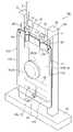
ports 13 and 14 may be changed as a method for preventing wrong attachment of the front and back sides of the soft container. For example, by making one of theports 13 and 14 arranged symmetrically shown in FIG. If the soft container is turned upside down, theports 13 and 14 do not enter the concave portion of the clamping plate, thereby preventing wrong attachment of the soft container on the front and back sides.

<第9実施形態>
図17は第9実施形態に係る充填装置を示す分解斜視図であり、図18は第9実施形態に係る充填装置を示す模式断面図である。本実施形態に係る充填装置1Hは、固定治具2Hの構造において上述の第1実施形態と異なるが、その他の構造は第1実施形態と同様である。
<Ninth Embodiment>
FIG. 17 is an exploded perspective view showing the filling device according to the ninth embodiment, and FIG. 18 is a schematic sectional view showing the filling device according to the ninth embodiment. Afilling device 1H according to this embodiment differs from the above-described first embodiment in the structure of afixture 2H, but other structures are the same as those in the first embodiment.

具体的には、軟質容器10Hにおいて、上側シール部11aの左右両端部には貫通孔18が1つずつ設けられ、下側シール部11bの左右両端部には貫通孔18が1つずつ設けられている。すなわち、軟質容器10Hの四隅部には、貫通孔18がそれぞれ1つずつ形成されている。 Specifically, in theflexible container 10H, one throughhole 18 is provided at each of the left and right ends of theupper seal portion 11a, and one throughhole 18 is provided at each of the left and right ends of thelower seal portion 11b. ing. That is, one throughhole 18 is formed in each of the four corners of theflexible container 10H.

一方、該軟質容器10Hを固定する固定治具2Hは、相対的に接近又は離間できる一対の挟持柱(挟持部材)53,54を一組とし、計2組を有するように構成されている。挟持柱53において、軟質容器10Hの上下方向に設けられた2つの貫通孔18に対応する位置には、貫通孔18に挿入可能な円錐台状の凸部53aがそれぞれ形成されている。一方、挟持柱53に対向して配置された挟持柱54には、挟持柱53の凸部53aに嵌合する凹部54aが形成されている。 On the other hand, the fixingjig 2H for fixing thesoft container 10H is configured to have a total of two sets of a pair of holding columns (holding members) 53 and 54 that can be relatively close to each other or separated from each other. In the holdingcolumn 53, truncatedconical projections 53a that can be inserted into the through-holes 18 are formed at positions corresponding to the two through-holes 18 provided in the vertical direction of thesoft container 10H. On the other hand, the holdingcolumn 54 arranged to face the holdingcolumn 53 is formed with aconcave portion 54 a that fits into theconvex portion 53 a of the holdingcolumn 53 .

軟質容器10Hは、貫通孔18に挿入された凸部53aが挟持柱54の凹部54aと嵌合することにより、挟持柱53,54に挟持された状態で固定されている。そして、収容室12への内容物の充填に影響を与えないように、軟質容器10Hの左側シール部11c及び右側シール部11dのみが挟持柱53,54に挟まれている。 Thesoft container 10H is fixed in a state of being clamped between the clampingcolumns 53 and 54 by fitting theconvex portion 53a inserted into the through-hole 18 into the recessedportion 54a of theclamping column 54. As shown in FIG. Only the leftside seal portion 11c and the rightside seal portion 11d of thesoft container 10H are sandwiched between the holdingcolumns 53 and 54 so as not to affect the filling of thestorage chamber 12 with the contents.

このように構成された充填装置1Hを用いた充填方法は、上述の第1実施形態と同様に、固定治具2Hに軟質容器10Hを固定させる固定ステップと、引き離し治具3を利用して軟質容器10Hの側面12L,12Rを互いに引き離す引き離しステップと、軟質容器10Hのポート13,14を介して収容室12の内部に内容物を充填する充填ステップと、を含む。 The filling method using thefilling device 1H configured as described above includes a fixing step of fixing thesoft container 10H to the fixingjig 2H and asoft container 10H using the separatingjig 3, as in the above-described first embodiment. It includes a separating step of separating thesides 12L and 12R of thecontainer 10H from each other, and a filling step of filling the inside of the containingchamber 12 with the contents through theports 13 and 14 of theflexible container 10H.

固定ステップでは、まず、挟持柱53,54を相対的に離間した状態で、軟質容器10Hの4つの貫通孔18に挟持柱53側の凸部53aをそれぞれ挿入するように、該軟質容器10Hを挟持柱53に引掛ける。続いて、挟持柱54の凹部54aと挟持柱53の凸部53aとを嵌合するように挟持柱54を挟持柱53に接近して、更にこれらの挟持柱53,54を突き合わせた状態で図示しない締結部材等でこれらの挟持柱53,54を固定締結する。これによって、軟質容器10Hは固定治具2Hに固定される。なお、引き離しステップ及び充填ステップ等は、上述の第1実施形態と同様のため、その説明を省略する。 In the fixing step, first, with the holdingcolumns 53 and 54 relatively separated, theflexible container 10H is moved so that theprojections 53a on the holdingcolumn 53 side are inserted into the four throughholes 18 of theflexible container 10H. It is hooked on theclamping column 53 . Subsequently, the holdingcolumn 54 is brought closer to the holdingcolumn 53 so that theconcave portion 54a of the holdingcolumn 54 and theconvex portion 53a of the holdingcolumn 53 are fitted, and the holdingcolumns 53 and 54 are shown in a state in which they are butted against each other. These clamping posts 53 and 54 are fixedly fastened with a fastening member or the like. As a result, thesoft container 10H is fixed to the fixingjig 2H. Note that the separating step, the filling step, and the like are the same as those in the above-described first embodiment, so the description thereof will be omitted.

本実施形態の充填装置1Hによれば、上述の第1実施形態と同様な作用効果を得られるほか、軟質容器10Hは左右方向で2組の挟持柱53,54に挟持されるので、軟質容器10Hをより安定した状態で固定することができる。 According to thefilling device 1H of the present embodiment, the same effects as those of the first embodiment can be obtained. 10H can be fixed in a more stable state.

軟質容器について、上述した内容のほか、様々な変形例が考えられる。例えば図19及び図20に示す変形例では、軟質容器10Jに設けられたポート13,14の下端は、更に収容室12の内部まで延設されている。好ましくは、ポート13,14の延設端(すなわち、下端)が収容室12の全体深さの20%以上に延びており、より好ましくは50%以上に延びている。このようにすれば、軟質容器10の側面12L及び側面12Rの間にポート13,14が介在されるので、樹脂フィルム同士のくっつきを抑制することができる。更に、吸盤3L,3Rで側面12L,12R同士を引き離す際に、吸盤3Lと吸盤3Rとの間にポート13,14が介在されるので、吸盤3Lと吸盤3Rとの間の真空状態の発生を抑制し、吸盤同士のくっつきを防止できる。その結果、吸盤3L,3Rは中心位置が重なるように対向して配置された場合であっても、軟質容器10の側面12L,12Rの引き離し作業をスムーズに行うことができる。 Regarding the flexible container, various modifications other than those described above are conceivable. For example, in the modification shown in FIGS. 19 and 20, the lower ends of theports 13 and 14 provided in thesoft container 10J are further extended to the interior of thestorage chamber 12. As shown in FIG. Preferably, the extended ends (ie, lower ends) ofports 13 and 14 extend more than 20% of the total depth ofchamber 12, more preferably more than 50%. With this configuration, theports 13 and 14 are interposed between the side surfaces 12L and 12R of theflexible container 10, so that sticking of the resin films can be suppressed. Furthermore, when the side surfaces 12L and 12R are pulled apart by thesuction cups 3L and 3R, theports 13 and 14 are interposed between thesuction cups 3L and 3R, so that a vacuum state can be generated between thesuction cups 3L and 3R. Suppresses and prevents sticking of suction cups. As a result, even when thesuction cups 3L and 3R are arranged so as to face each other so that their central positions overlap, the side surfaces 12L and 12R of thesoft container 10 can be smoothly separated.

一方、ポート13,14の介在によって吸盤3L,3R同士の押し合う力の低下を招くことが考えられる。ここで、ポート13,14の介在による吸盤3L,3R同士の押し合いへの影響を抑制するために、ポート13,14は変形しやすい可撓性の材料に形成されることが好ましい。また、ポート13,14に切り込みを複数入れることで、変形させやすくしても良い。 On the other hand, it is conceivable that the interveningports 13 and 14 may reduce the pressing force between thesuction cups 3L and 3R. Here, in order to suppress the influence of the interposition of theports 13 and 14 on the mutual pressing of thesuction cups 3L and 3R, theports 13 and 14 are preferably made of a flexible material that is easily deformed. In addition, theports 13 and 14 may be provided with a plurality of cuts to facilitate deformation.

また、図21に示す変形例では、軟質容器10Kの側面12Lに取っ手57、側面12Rに取っ手58がそれぞれ設けられている。取っ手57,58は、例えば長尺状の樹脂テープの両端部を熱溶着や接着で樹脂フィルムと固定し、両端部間の中間部を樹脂フィルムから遊離した状態で形成されている。このように構成された取っ手57,58を使うときに、遊離した中間部を上述した駆動機構に取り付けて使用して良く、或いは作業者が直接中間部を引っ張ることで側面12L,12R同士を引き離しても良い。この場合、上述した引き離し治具3を省くことができる。 In the modification shown in FIG. 21, ahandle 57 is provided on theside surface 12L of thesoft container 10K, and ahandle 58 is provided on theside surface 12R. Thehandles 57 and 58 are formed, for example, by fixing both ends of a long resin tape to the resin film by thermal welding or adhesion, and separating the intermediate portion between the ends from the resin film. When using thehandles 57, 58 constructed in this way, the loose intermediate portion may be attached to the drive mechanism described above, or the operator may pull the intermediate portion directly to separate the side surfaces 12L, 12R. can be In this case, theseparation jig 3 described above can be omitted.

<充填用針の構造>
以下、図23を参照して充填用針4の構造を説明する。図23に示すように、充填用針4は、内部に軸方向Lに延在する内容物流路43が設けられた円筒状の針本体41と、針本体41から軸方向Lの前方に先細りするとともに、内容物流路43と連通する内容物吐出口44が設けられた針先部42とを有する。内容物流路43は、例えば断面円形状を呈しており、その直径は0.05mm~1.5mmであることが好ましく、0.4mm~1.0mmであることがより好ましい。
<Structure of filling needle>
The structure of the fillingneedle 4 will be described below with reference to FIG. As shown in FIG. 23 , the fillingneedle 4 includes acylindrical needle body 41 provided with acontent flow path 43 extending in the axial direction L, and aneedle body 41 tapering forward in the axial direction L from theneedle body 41 . It also has aneedle tip portion 42 provided with acontent discharge port 44 that communicates with thecontent flow path 43 . Thecontent channel 43 has, for example, a circular cross-section, and preferably has a diameter of 0.05 mm to 1.5 mm, more preferably 0.4 mm to 1.0 mm.

針先部42には、内容物流路43を流れる内容物の流れ方向を軸方向Lに対して傾斜させるガイド壁部42aが設けられている。図23に示すように、ガイド壁部42aは、針先部42の先端部に配置されており、軸方向Lに対して所定の角度αで傾斜している。ここで、角度αは15°~30°であることが好ましい。 Theneedle tip portion 42 is provided with aguide wall portion 42a that tilts the flow direction of the content flowing through thecontent flow path 43 with respect to the axial direction L. As shown in FIG. As shown in FIG. 23, theguide wall portion 42a is arranged at the distal end portion of theneedle tip portion 42 and is inclined with respect to the axial direction L at a predetermined angle α. Here, the angle α is preferably between 15° and 30°.

従来の充填用針を用いて内容物を収容室の内部に充填する場合、内容物吐出口から出た内容物は、充填用針の軸方向Lに沿ってまっすぐに排出される。そして、軟質容器を形成する樹脂フィルム同士が静電気等でくっついて密着した場合、排出された内容物が内容物吐出口に跳ね返されやすく、内容物の逆流を招いてしまう。 When the content is filled into the storage chamber using a conventional filling needle, the content discharged from the content discharge port is discharged straight along the axial direction L of the filling needle. If the resin films forming the flexible container stick together due to static electricity or the like, the discharged contents are likely to rebound to the contents discharge port, causing backflow of the contents.

一方、本実施形態の充填用針4では、内容物流路43を流れる内容物の流れ方向を軸方向Lに対して傾斜させるガイド壁部42aが設けられるので、内容物吐出口44から出た内容物が軸方向Lに対し傾斜して排出され、言い換えれば、内容物吐出口44から出た内容物が軸方向Lの横方向に排出される。このため、仮に内容物が跳ね返されても、内容物吐出口44に戻る量が少なくなるので、逆流を抑制することができる。更に、軸方向Lに対するガイド壁部42aの傾斜角度αは15°~30°と設定された場合、跳ね返された内容物による内容物吐出口44への戻りを防止でき、且つガイド壁部42aの設置による内容物流れの抵抗増加を抑制することができる。 On the other hand, the fillingneedle 4 of the present embodiment is provided with theguide wall portion 42a that inclines the flow direction of the content flowing through thecontent flow path 43 with respect to the axial direction L, so that the content discharged from thecontent discharge port 44 is The object is discharged obliquely with respect to the axial direction L, in other words, the content discharged from thecontent discharge port 44 is discharged laterally in the axial direction L. Therefore, even if the contents bounce back, the amount of the contents returning to the contents dischargeport 44 is reduced, so that backflow can be suppressed. Further, when the inclination angle α of theguide wall portion 42a with respect to the axial direction L is set to 15° to 30°, it is possible to prevent the rebounded content from returning to thecontent discharge port 44, and theguide wall portion 42a It is possible to suppress an increase in content flow resistance due to installation.

充填用針4は、金属、ガラス又はプラスチック等の材料によって形成されて良く、接触による軟質容器10へのダメージ等を抑制するために、少なくとも針先部42の外側部分はプラスチックで形成されることが望ましい。 The fillingneedle 4 may be made of a material such as metal, glass, or plastic, and at least the outer portion of theneedle tip 42 should be made of plastic in order to prevent damage to thesoft container 10 due to contact. is desirable.

以上、本発明の実施形態について詳述したが、本発明は、上記の実施形態に限定されるものではなく、特許請求の範囲に記載された本発明の精神を逸脱しない範囲で、種々の設計変更を行うことができるものである。例えば、上述の実施形態では、固定治具と引き離し治具とを備える充填装置の例を説明したが、本発明は、固定治具及び引き離し治具のいずれか一方を備える充填装置にも適用される。 Although the embodiments of the present invention have been described in detail above, the present invention is not limited to the above-described embodiments, and various designs can be made without departing from the spirit of the invention described in the claims. Changes can be made. For example, in the above-described embodiments, an example of a filling device provided with a fixing jig and a separating jig was described, but the present invention is also applicable to a filling device provided with either one of the fixing jig and the separating jig. be.

1,1A,1B,1C,1D,1E,1F,1G,1H,1J 充填装置
2,2A,2B,2C,2D,2E,2F,2G,2H 固定治具
3 引き離し治具
3L,3R 吸盤(吸着部)
4 充填用針
10,10A,10B,10C,10D,10F,10G,10H,10J,10K 軟質容器
11 シール部
12 収容室
12L,12R 側面
13,14 ポート
15 密閉栓
16,18 貫通孔
21,22 側壁部
21a,22a 開口部
41 針本体
42 針先部
42a ガイド壁部
43 内容物流路
44 内容物吐出口
51,52 挟持板(挟持部材)
53,54 挟持柱(挟持部材)
1, 1A, 1B, 1C, 1D, 1E, 1F, 1G, 1H,1J Filling device 2, 2A, 2B, 2C, 2D, 2E, 2F, 2G,2H Fixing jig 3Separating jig 3L, 3R Suction cup ( suction part)
4 Fillingneedles 10, 10A, 10B, 10C, 10D, 10F, 10G, 10H, 10J,10K Soft container 11Seal part 12Storage chambers 12L,12R Sides 13, 14Port 15Closures 16, 18 Throughholes 21, 22Side wall portions 21a,22a Opening portion 41 Needlemain body 42Needle tip portion 42aGuide wall portion 43 Contents flowpath 44 Contents dischargeports 51, 52 Holding plate (holding member)
53, 54 holding column (holding member)

Claims (7)

Translated fromJapanese
ポートと少なくとも一対の側面を有する収容室とを備えた軟質容器に対し、前記ポートを介して前記収容室の内部に内容物を充填する充填装置であって、
前記軟質容器を固定する固定治具、及び前記収容室の前記一対の側面を相対的に引き離す引き離し治具を備え、
前記固定治具は、前記軟質容器を挟持する少なくとも一対の挟持部材を有し、
前記一対の挟持部材のうち一方には前記軟質容器に設けられた貫通孔に挿入可能な凸部が設けられ、他方には前記凸部と嵌合する凹部が設けられていることを特徴とする充填装置。
A filling device for filling a flexible container comprising a port and a containing chamber having at least a pair of side surfaces with contents into the containing chamber through the port,
A fixing jig for fixing the soft container and a separating jig for separating the pair of side surfaces of the storage chamber,
The fixing jig has at least a pair of clamping members that clamp the soft container,
One of the pair of holding members is provided with a convex portion that can be inserted into a through hole provided in the soft container, and the other is provided with a concave portion that fits with the convex portion. filling device.
前記引き離し治具は、前記収容室の前記一対の側面を吸着する一対の吸着部を有する請求項1に記載の充填装置。2. The filling device according to claim1 , wherein said separation jig has a pair of suction portions for suctioning said pair of side surfaces of said storage chamber. 前記一対の吸着部は、中心位置がずれた状態で対向して配置されている請求項に記載の充填装置。3. The filling device according to claim2 , wherein the pair of suction parts are arranged facing each other with their centers shifted. 前記ポートが前記収容室の内部まで延設された場合において、前記一対の吸着部は、間に前記ポートが介在された状態で対向して配置されている請求項に記載の充填装置。3. The filling device according to claim2 , wherein when the port extends to the interior of the storage chamber, the pair of suction portions are arranged to face each other with the port interposed therebetween. 前記充填装置は、前記ポートから前記収容室の内部に挿入して内容物を充填するための充填用針を更に備え、
前記充填用針は、内部に軸方向に延在する内容物流路が設けられた針本体と、前記内容物流路と連通する内容物吐出口が設けられた針先部とを備え、
前記針先部には、前記内容物流路を流れる内容物の流れ方向を前記軸方向に対して傾斜させるガイド壁部が設けられている請求項1~のいずれか一項に記載の充填装置。
The filling device further comprises a filling needle for inserting into the storage chamber from the port to fill the contents,
The filling needle includes a needle body provided with a content flow path extending in the axial direction, and a needle tip provided with a content discharge port communicating with the content flow path,
The filling device according to any one of claims 1 to4 , wherein the needle tip portion is provided with a guide wall portion that inclines the flow direction of the content flowing through the content channel with respect to the axial direction. .
前記ガイド壁部は、前記軸方向に対して15°~30°傾斜する請求項に記載の充填装置。6. The filling device according to claim5 , wherein the guide wall portion is inclined by 15° to 30° with respect to the axial direction. 請求項1~のいずれか一項に記載の充填装置を用いた充填方法であって、
前記固定治具に前記軟質容器を固定させる固定ステップと、
前記引き離し治具を利用して前記収容室の前記一対の側面を相対的に引き離す引き離しステップと、
前記ポートを介して前記収容室の内部に内容物を充填する充填ステップと、
を含むことを特徴とする充填方法。
A filling method using the filling device according to any one of claims 1 to6 ,
a fixing step of fixing the flexible container to the fixing jig;
a separating step of using the separating jig to separate the pair of side surfaces of the storage chamber from each other;
a filling step of filling contents into the storage chamber through the port;
A filling method comprising:
JP2018014151A2018-01-302018-01-30 Filling device, filling method and filling needleActiveJP7119393B2 (en)

Priority Applications (2)

Application NumberPriority DateFiling DateTitle
JP2018014151AJP7119393B2 (en)2018-01-302018-01-30 Filling device, filling method and filling needle
JP2022098769AJP7416132B2 (en)2018-01-302022-06-20 Filling device, filling method and filling needle

Applications Claiming Priority (1)

Application NumberPriority DateFiling DateTitle
JP2018014151AJP7119393B2 (en)2018-01-302018-01-30 Filling device, filling method and filling needle

Related Child Applications (1)

Application NumberTitlePriority DateFiling Date
JP2022098769ADivisionJP7416132B2 (en)2018-01-302022-06-20 Filling device, filling method and filling needle

Publications (2)

Publication NumberPublication Date
JP2019131231A JP2019131231A (en)2019-08-08
JP7119393B2true JP7119393B2 (en)2022-08-17

Family

ID=67545462

Family Applications (2)

Application NumberTitlePriority DateFiling Date
JP2018014151AActiveJP7119393B2 (en)2018-01-302018-01-30 Filling device, filling method and filling needle
JP2022098769AActiveJP7416132B2 (en)2018-01-302022-06-20 Filling device, filling method and filling needle

Family Applications After (1)

Application NumberTitlePriority DateFiling Date
JP2022098769AActiveJP7416132B2 (en)2018-01-302022-06-20 Filling device, filling method and filling needle

Country Status (1)

CountryLink
JP (2)JP7119393B2 (en)

Citations (4)

* Cited by examiner, † Cited by third party
Publication numberPriority datePublication dateAssigneeTitle
JP2001058602A (en)1999-08-232001-03-06Fuji Seal IncMethod and device for filling pouch container with spout
JP2008143526A (en)2006-12-062008-06-26Fuji Seal International IncPouch container
JP2008174297A (en)2007-01-222008-07-31Toyo Seikan Kaisha LtdMethod for filling and sealing liquid content into pouch with spout and device for the same
JP2013142001A (en)2012-01-122013-07-22Toyo Jidoki Co LtdMethod and device for opening mouth of bag

Family Cites Families (4)

* Cited by examiner, † Cited by third party
Publication numberPriority datePublication dateAssigneeTitle
JPS49109192A (en)*1973-02-201974-10-17
JPS602608U (en)*1983-06-201985-01-10三菱重工業株式会社 bag opening device
FR2767583B1 (en)*1997-08-201999-10-22Junior Instruments DEVICE FOR THE COLLECTION AND / OR INJECTION INSIDE A MOUTH SAMPLE TUBE
EP3142731A4 (en)*2014-05-102018-01-17Dr. Py Institute, LLCSelf closing and opening filling needle, needle holder, filler and method

Patent Citations (4)

* Cited by examiner, † Cited by third party
Publication numberPriority datePublication dateAssigneeTitle
JP2001058602A (en)1999-08-232001-03-06Fuji Seal IncMethod and device for filling pouch container with spout
JP2008143526A (en)2006-12-062008-06-26Fuji Seal International IncPouch container
JP2008174297A (en)2007-01-222008-07-31Toyo Seikan Kaisha LtdMethod for filling and sealing liquid content into pouch with spout and device for the same
JP2013142001A (en)2012-01-122013-07-22Toyo Jidoki Co LtdMethod and device for opening mouth of bag

Also Published As

Publication numberPublication date
JP2022113910A (en)2022-08-04
JP2019131231A (en)2019-08-08
JP7416132B2 (en)2024-01-17

Similar Documents

PublicationPublication DateTitle
EP2818190B1 (en)Medical device packaging body
JP7394834B2 (en) Prefilled syringe storage tray and packaging using the same
JP5432176B2 (en) Connector
CN110127180B (en)Holding member and packaging structure for component for medicine container
JP2003159328A (en)Two-chamber type prefilled syringe
JP6878924B2 (en) Liquid feeding method, liquid feeding device and container filled with contents
JPWO2013035543A1 (en) Medical container and method for producing medical container
JP7119393B2 (en) Filling device, filling method and filling needle
JP2020055646A (en)Ptp sheet for drug packaging
JP6834181B2 (en) Multi-chamber container for freezing
JP2019005388A (en) Cell storage container
WO2016103485A1 (en)Culture flask
WO2021106425A1 (en)Infusion cartridge and infusion pump
JP6088742B2 (en) Fluid ejection method and apparatus
JP7327611B2 (en) Filling needle and filling device provided with the same, soft container
US11964790B2 (en)Device for emptying a flexible bag
EP4112035B1 (en)Tray for positioning a medical vial together with a vial adapter in a fixed positional relationship relative to each other and packaging unit comprising the same
JP5390276B2 (en) Medical tool set
JP7172329B2 (en) Filling needle and filling device provided with the same, soft container
JP5542403B2 (en) Small container
JP4412468B2 (en) MEDICAL MIXED CHEMICAL SOLID BODY AND SEALING METHOD
KR100579915B1 (en) Ringer&#39;s disease
US20220204914A1 (en)Biological component cassette, biological component kit, and biological component treatment system
JP2021072966A (en)Multi-chamber container for freezing
JP4010900B2 (en) Syringe

Legal Events

DateCodeTitleDescription
A621Written request for application examination

Free format text:JAPANESE INTERMEDIATE CODE: A621

Effective date:20201127

A977Report on retrieval

Free format text:JAPANESE INTERMEDIATE CODE: A971007

Effective date:20211117

A131Notification of reasons for refusal

Free format text:JAPANESE INTERMEDIATE CODE: A131

Effective date:20211130

A521Request for written amendment filed

Free format text:JAPANESE INTERMEDIATE CODE: A523

Effective date:20220121

A131Notification of reasons for refusal

Free format text:JAPANESE INTERMEDIATE CODE: A131

Effective date:20220510

A521Request for written amendment filed

Free format text:JAPANESE INTERMEDIATE CODE: A523

Effective date:20220620

TRDDDecision of grant or rejection written
A01Written decision to grant a patent or to grant a registration (utility model)

Free format text:JAPANESE INTERMEDIATE CODE: A01

Effective date:20220705

A61First payment of annual fees (during grant procedure)

Free format text:JAPANESE INTERMEDIATE CODE: A61

Effective date:20220718

R150Certificate of patent or registration of utility model

Ref document number:7119393

Country of ref document:JP

Free format text:JAPANESE INTERMEDIATE CODE: R150


[8]ページ先頭

©2009-2025 Movatter.jp