JP7118241B2 - Staging assembly for specimen imaging system - Google Patents
Staging assembly for specimen imaging systemDownload PDFInfo
- Publication number
- JP7118241B2 JP7118241B2JP2021505678AJP2021505678AJP7118241B2JP 7118241 B2JP7118241 B2JP 7118241B2JP 2021505678 AJP2021505678 AJP 2021505678AJP 2021505678 AJP2021505678 AJP 2021505678AJP 7118241 B2JP7118241 B2JP 7118241B2
- Authority
- JP
- Japan
- Prior art keywords
- staging
- assembly
- dock
- manifold
- inlet
- Prior art date
- Legal status (The legal status is an assumption and is not a legal conclusion. Google has not performed a legal analysis and makes no representation as to the accuracy of the status listed.)
- Active
Links
Images


Classifications
- A—HUMAN NECESSITIES
- A61—MEDICAL OR VETERINARY SCIENCE; HYGIENE
- A61D—VETERINARY INSTRUMENTS, IMPLEMENTS, TOOLS, OR METHODS
- A61D7/00—Devices or methods for introducing solid, liquid, or gaseous remedies or other materials into or onto the bodies of animals
- A61D7/04—Devices for anaesthetising animals by gases or vapours; Inhaling devices
- A—HUMAN NECESSITIES
- A61—MEDICAL OR VETERINARY SCIENCE; HYGIENE
- A61D—VETERINARY INSTRUMENTS, IMPLEMENTS, TOOLS, OR METHODS
- A61D3/00—Appliances for supporting or fettering animals for operative purposes
- A—HUMAN NECESSITIES
- A61—MEDICAL OR VETERINARY SCIENCE; HYGIENE
- A61M—DEVICES FOR INTRODUCING MEDIA INTO, OR ONTO, THE BODY; DEVICES FOR TRANSDUCING BODY MEDIA OR FOR TAKING MEDIA FROM THE BODY; DEVICES FOR PRODUCING OR ENDING SLEEP OR STUPOR
- A61M16/00—Devices for influencing the respiratory system of patients by gas treatment, e.g. ventilators; Tracheal tubes
- A61M16/0087—Environmental safety or protection means, e.g. preventing explosion
- A61M16/009—Removing used or expired gases or anaesthetic vapours
- A—HUMAN NECESSITIES
- A61—MEDICAL OR VETERINARY SCIENCE; HYGIENE
- A61M—DEVICES FOR INTRODUCING MEDIA INTO, OR ONTO, THE BODY; DEVICES FOR TRANSDUCING BODY MEDIA OR FOR TAKING MEDIA FROM THE BODY; DEVICES FOR PRODUCING OR ENDING SLEEP OR STUPOR
- A61M16/00—Devices for influencing the respiratory system of patients by gas treatment, e.g. ventilators; Tracheal tubes
- A61M16/01—Devices for influencing the respiratory system of patients by gas treatment, e.g. ventilators; Tracheal tubes specially adapted for anaesthetising
Landscapes
- Health & Medical Sciences (AREA)
- Life Sciences & Earth Sciences (AREA)
- Veterinary Medicine (AREA)
- Zoology (AREA)
- Engineering & Computer Science (AREA)
- Wood Science & Technology (AREA)
- Animal Behavior & Ethology (AREA)
- General Health & Medical Sciences (AREA)
- Public Health (AREA)
- Anesthesiology (AREA)
- Animal Husbandry (AREA)
- Sampling And Sample Adjustment (AREA)
- Testing Of Engines (AREA)
- Apparatus Associated With Microorganisms And Enzymes (AREA)
Description
Translated fromJapanese関連出願の相互参照
本出願は、2018年8月2日に出願された、US非仮特許出願第16/053,134号の優先権を主張する。この文献の内容は、参照することにより、その全体が、明白に、本明細書に組み込まれる。CROSS-REFERENCE TO RELATED APPLICATIONS This application claims priority to US Non-Provisional Patent Application No. 16/053,134, filed August 2, 2018. The contents of this document are expressly incorporated herein in their entirety by reference.
撮像システムは、標本、たとえばマウス及びラットを検査して、標本の腫瘍などの病状を評価するために使用される。撮像システムは、たとえば、x線、蛍光発光、または生物発光を使用する場合があり、また、標本が、検査中に動かないことが必要である場合がある。標本を動かなくするために、麻酔が使用される。 Imaging systems are used to examine specimens, such as mice and rats, to assess disease states, such as tumors, in specimens. Imaging systems may use, for example, x-rays, fluorescence, or bioluminescence, and may require that the specimen be stationary during examination. Anesthesia is used to immobilize the specimen.
従来技術の撮像システムは、1つまたは複数の標本が個別に配置される検査チャンバを含んでいる。たとえばガスの形態の麻酔は、標本の鼻先の周りに配置されたノーズコーンに搬送される。次いで、残りの麻酔ガスが検査チャンバから排出される。いくつかの条件では、残りの麻酔ガスは、検査チャンバから完全には排出されない。 Prior art imaging systems include examination chambers in which one or more specimens are individually positioned. Anesthesia, for example in the form of gas, is delivered to a nosecone placed around the nose tip of the specimen. The remaining anesthetic gas is then exhausted from the examination chamber. In some conditions, residual anesthetic gas is not completely exhausted from the examination chamber.
さらに、標本の複数のグループが検査されることになる場合、各グループの各標本が個別に検査チャンバ内に配置され、麻酔が標本に搬送され、撮像が行われ、次いで、標本のグループが検査チャンバから除かれる。第1のグループの撮像が完了すると、標本の連続したグループの各々に関してプロセスが繰り返される。 Additionally, if multiple groups of specimens are to be examined, each specimen in each group is individually placed in the examination chamber, anesthesia is delivered to the specimens, imaging is performed, and then the groups of specimens are examined. removed from the chamber. Once imaging of the first group is complete, the process is repeated for each successive group of specimens.
従来の既知のデバイスに本来含まれる困難性のいくつかまたはすべてを低減するか克服する、標本撮像システムのためのステージングアセンブリを提供することが望ましい。具体的な目的及び利点は、特定の実施形態の以下の開示及び詳細な記載の観点から、当業者、すなわち、当該技術分野の知識があるか、経験を積んだ者には明らかとるであろう。 It would be desirable to provide a staging assembly for a specimen imaging system that reduces or overcomes some or all of the difficulties inherent in previously known devices. Specific objects and advantages will become apparent to those skilled in the art, i.e., those knowledgeable or experienced in the art, in view of the ensuing disclosure and detailed description of specific embodiments. .
第1の態様によれば、標本撮像マシンのためのステージングアセンブリが、流入開口及び流出開口を有するハウジングを伴うマニホルドアセンブリを含んでいる。複数のチャンバの各々は、チャンバ開口を有している。導管は、チャンバを流入開口及び流出開口と流体連通させる。底部プレートは、チャンバの下部に延びている。マニホルドアセンブリは、取付けアセンブリを含んでいる。ステージングドックは、ベース、ステージングドック麻酔流入口、及び、マニホルドアセンブリの流入開口によって受領可能であり、バルブを含むステージングドック麻酔流出口を含んでいる。ステージングドック排出流入口は、マニホルドアセンブリの流出開口によって受領可能である。ステージングドックは、ステージングドック排出流出口を含んでいる。ステージングドック取付けアセンブリは、マニホルド取付けアセンブリに取外し可能に取付け可能である。 According to a first aspect, a staging assembly for a specimen imaging machine includes a manifold assembly with a housing having an inflow opening and an outflow opening. Each of the multiple chambers has a chamber opening. A conduit fluidly communicates the chamber with the inflow opening and the outflow opening. A bottom plate extends to the bottom of the chamber. The manifold assembly includes a mounting assembly. The staging dock includes a staging dock anesthesia outlet that is receivable by the base, a staging dock anesthesia inlet, and an inlet opening of the manifold assembly and includes a valve. A staging dock discharge inlet is receivable by an outlet opening of the manifold assembly. The staging dock includes a staging dock discharge outlet. A staging dock mounting assembly is removably attachable to the manifold mounting assembly.
別の態様によれば、動物撮像マシンのためのステージングアセンブリは、流入開口、流入開口と流体連通している流入導管、流入導管と流体連通している複数のチャンバ流入導管、流出開口、流出開口と流体連通している流出導管、及び、流出導管と流体連通している複数のチャンバ流出導管を有するハウジングを伴う、マニホルドアセンブリを含む場合がある。複数のチャンバの各々は、チャンバの頂部にあり、チャンバ流入導管の1つと流体連通しているチャンバ流入口、チャンバ開口、及び、一対のチャンバ流出口であって、各チャンバ流出口が、チャンバの一方側かつ底部に配置され、チャンバとチャンバ流出導管の1つとの間に延びる、一対のチャンバ流出口を含む場合がある。前部プレートはチャンバ開口を規定し、底部プレートはチャンバの各々の下に延びる。マニホルドアセンブリは、マニホルド取付けアセンブリを含んでいる。ステージングドックは、ベース、麻酔流入口、及び、マニホルドアセンブリの流入開口によって受領可能であり、バルブを含むマニホルド流出口を含んでいる。排出流入口は、マニホルドアセンブリの流出開口によって受領可能である。ステージングドックは、排出流出口を含んでいる。ステージングドック取付けアセンブリは、マニホルド取付けアセンブリに取外し可能に取付け可能である。 According to another aspect, a staging assembly for an animal imaging machine includes an inlet opening, an inlet conduit in fluid communication with the inlet opening, a plurality of chamber inlet conduits in fluid communication with the inlet conduit, an outlet opening, an outlet opening. A manifold assembly with a housing having an outflow conduit in fluid communication with the outflow conduit and a plurality of chamber outflow conduits in fluid communication with the outflow conduit. Each of the plurality of chambers has a chamber inlet at the top of the chamber and in fluid communication with one of the chamber inlet conduits, a chamber opening, and a pair of chamber outlets, each chamber outlet being associated with the chamber. It may include a pair of chamber outlets located on one side and bottom and extending between the chamber and one of the chamber outlet conduits. A front plate defines chamber openings and a bottom plate extends under each of the chambers. The manifold assembly includes a manifold mounting assembly. The staging dock includes a base, an anesthesia inlet, and a manifold outlet that is receivable by the inlet opening of the manifold assembly and includes a valve. The exhaust inlet is receivable by an outlet opening of the manifold assembly. The staging dock includes a discharge outlet. A staging dock mounting assembly is removably attachable to the manifold mounting assembly.
本明細書に開示されるこれら及び追加の特徴及び利点は、特定の実施形態の以下の詳細な開示、その図面、及び特許請求の範囲からさらに理解されることになるであろう。 These and additional features and advantages disclosed herein will be further understood from the following detailed disclosure of specific embodiments, the drawings thereof, and the claims.
本実施形態の前述及び他の特徴及び利点は、添付図面と合わせて取られる、説明的な実施形態の以下の詳細な説明から、より完全に理解されるであろう。
本明細書は、例えば、以下の項目も提供する。
(項目1)
流入開口及び流出開口を有するハウジング、
複数のチャンバであって、各チャンバがチャンバ開口を有する、前記複数のチャンバ、
前記チャンバを前記流入開口及び前記流出開口と流体連通させる複数の導管、
前記チャンバの各々の下に延びる底部プレート、ならびに、
マニホルド取付けアセンブリ、
を備えるマニホルドアセンブリと、
ベース、
ステージングドック麻酔流入口、
前記マニホルドアセンブリの前記流入開口によって受領可能であり、バルブを含むステージングドック麻酔流出口、
前記マニホルドアセンブリの前記流出開口によって受領可能であるステージングドック排出流入口、
ステージングドック排出流出口、及び、
前記マニホルド取付けアセンブリに取外し可能に取付け可能なステージングドック取付けアセンブリ、
を備えるステージングドックと、を備えた標本撮像マシンのためのステージングアセンブリ。
(項目2)
前記マニホルドアセンブリハウジングに取外し可能に固定された複数のバッフルであって、各バッフルが、隣接するチャンバ開口間に配置される、前記複数のバッフルをさらに備えている、項目1に記載のステージングアセンブリ。
(項目3)
前記底部プレートが、前記マニホルドアセンブリから外向きに延びて、ステージングトレーを形成する、項目2に記載のステージングアセンブリ。
(項目4)
複数の対のピンであって、各ピンが、前記ステージングトレーの前記底部プレートから上方に延び、各バッフルが、前記対のピンの1つの各ピン間に配置されるとともに、各ピンに当接する、前記複数の対のピンをさらに備えている、項目3に記載のステージングアセンブリ。
(項目5)
前記底部プレートの頂部表面に固定された対のハンドルをさらに備えている、項目3に記載のステージングアセンブリ。
(項目6)
前記マニホルドアセンブリハウジングの前面に形成された複数のスロットであって、各スロットが前記バッフルの1つを受領するように構成されている、前記複数のスロットをさらに備える、項目3に記載のステージングアセンブリ。
(項目7)
前記マニホルドアセンブリが4つのバッフルを含む、項目3に記載のステージングアセンブリ。
(項目8)
前記ステージングドックが、前記ベースから下方に延びることができる後退可能な対のピンを含む、項目1に記載のステージングアセンブリ。
(項目9)
前記マニホルド取付けアセンブリと前記ステージングドック取付けアセンブリとの少なくとも1つが、一対の磁石を備える、項目1に記載のステージングアセンブリ。
(項目10)
前記チャンバの上方に、前記マニホルドアセンブリに沿って配置された複数の基準要素をさらに備える、項目1に記載のステージングアセンブリ。
(項目11)
前記基準要素が、非蛍光性の放射線透過性材料で形成されている、項目10に記載のステージングアセンブリ。
(項目12)
ポージングトレーと、
ポージングステーション麻酔流入口と、
前記マニホルドアセンブリの前記流入開口によって受領可能であり、バルブを含むポージングステーション麻酔流出口と、
前記マニホルドアセンブリの前記流出開口によって受領可能であるポージングステーション排出流入口と、
ポージングステーション排出流出口と、
前記マニホルド取付けアセンブリに取外し可能に取付け可能なポージングステーション取付けアセンブリと、
を備えるポージングステーションをさらに備えた、項目1に記載のステージングアセンブリ。
(項目13)
前記マニホルド取付けアセンブリと前記ポージングステーション取付けアセンブリとの少なくとも1つが、一対の磁石を備える、項目12に記載のステージングアセンブリ。
(項目14)
前記ポージングトレーが加熱される、項目12に記載のステージングアセンブリ。
(項目15)
前記バルブが、
バルブ本体であって、前記ステージングドックの前記ベースに形成されたキャビティと流体連通する筒状開口であって、前記キャビティが、前記麻酔流入口と流体連通している、前記筒状開口、ならびに、前記筒状開口及び前記バルブ本体の外部と流体連通するアパーチャを含む、前記バルブ本体と、
シャフトであって、前記シャフトと前記筒状開口との間に隙間を画定するように、前記筒状開口内に移動可能に受領される前記シャフト、及び、前記シャフトの第1の端部にあり、前記キャビティ内に移動可能に受領されるプラグと、
前記キャビティ内に着座し、前記プラグを前記隙間に向けて付勢するバネと、
前記プラグと前記隙間との間に配置されたシーリング部材と、
を備える、項目1に記載のステージングアセンブリ。
(項目16)
前記バネが円錐型バネである、項目15に記載のステージングアセンブリ。
(項目17)
前記ハウジングの外部表面に形成された溝に着座したOリングをさらに備える、項目15に記載のステージングアセンブリ。
(項目18)
前記シーリング部材がガスケットである、項目15に記載のステージングアセンブリ。
(項目19)
前記シャフトの第2の端部にキャップをさらに備える、項目15に記載のステージングアセンブリ。
(項目20)
前記キャップと前記バルブ本体との間の前記隙間の端部に配置されたベアリングをさらに備える、項目19に記載のステージングアセンブリ。
(項目21)
流入開口、前記流入開口と流体連通する流入導管、前記流入導管と流体連通する複数のチャンバ流入導管、流出開口、前記流出開口と流体連通する流出導管、及び、前記流出導管と流体連通する複数のチャンバ流出導管を有するハウジング、
複数のチャンバであって、各チャンバが、前記チャンバの頂部にあり、前記チャンバ流入導管の1つと流体連通するチャンバ流入口、チャンバ開口、及び、一対のチャンバ流出口であって、各チャンバ流出口が、前記チャンバの一方側かつ底部に配置され、前記チャンバと前記チャンバ流出導管の1つとの間に延びる、前記一対のチャンバ流出口を含む、前記複数のチャンバ、
前記チャンバ開口を画定する前部プレート、
前記チャンバの各々の下に延びる底部プレート、
マニホルド取付けアセンブリ、ならびに、
前記ハウジングに取外し可能に固定された複数のバッフルであって、各バッフルが、隣接するチャンバ開口間に配置されている、前記複数のバッフル、
を備えるマニホルドアセンブリと、
ベース、
麻酔流入口、
前記マニホルドアセンブリの前記流入開口によって受領可能であり、バルブを含むマニホルド流出口、
前記マニホルドアセンブリの前記流出開口によって受領可能である排出流入口、
排出流出口、及び、
前記マニホルド取付けアセンブリに取外し可能に取付け可能なステージングドック取付けアセンブリ、
を備えるステージングドックと、を備える動物撮像マシンのためのステージングアセンブリ。
(項目22)
前記ハウジングに受領されたマニホルドブロックをさらに備え、前記流入開口、前記流入導管、前記流出開口、前記流出導管、前記チャンバ流入導管、及び前記チャンバ流出導管が、前記マニホルドブロックの少なくとも一部を通って延びる穴を含んでいる、項目21に記載のステージングアセンブリ。
(項目23)
複数のプラグであって、前記プラグの1つが、前記流入導管、前記流出導管、及び前記チャンバ流入導管の各々の端部に挿入される、前記複数のプラグをさらに備える、項目22に記載のステージングアセンブリ。
(項目24)
前記プラグがネジを備える、項目23に記載のステージングアセンブリ。
(項目25)
前記ネジの少なくともいくつかが、放射線透過性材料で形成される、項目24に記載のステージングアセンブリ。The foregoing and other features and advantages of the present embodiments will be more fully understood from the following detailed description of illustrative embodiments taken in conjunction with the accompanying drawings.
This specification also provides the following items, for example.
(Item 1)
a housing having an inflow opening and an outflow opening;
a plurality of chambers, each chamber having a chamber opening;
a plurality of conduits placing the chamber in fluid communication with the inflow opening and the outflow opening;
a bottom plate extending under each of said chambers; and
manifold mounting assembly,
a manifold assembly comprising
base,
staging dock anesthesia inlet,
a staging dock anesthesia outlet receivable by the inlet opening of the manifold assembly and including a valve;
a staging dock discharge inlet receivable by the outlet opening of the manifold assembly;
a staging dock discharge outlet; and
a staging dock mounting assembly removably attachable to said manifold mounting assembly;
and a staging assembly for a specimen imaging machine.
(Item 2)
The staging assembly of item 1, further comprising a plurality of baffles removably secured to the manifold assembly housing, each baffle positioned between adjacent chamber openings.
(Item 3)
3. The staging assembly of item 2, wherein the bottom plate extends outwardly from the manifold assembly to form a staging tray.
(Item 4)
a plurality of pairs of pins, each pin extending upwardly from the bottom plate of the staging tray, each baffle being disposed between and abutting each pin of one of the pairs of pins; 4. The staging assembly of claim 3, further comprising: , said plurality of pairs of pins.
(Item 5)
4. The staging assembly of item 3, further comprising a pair of handles secured to the top surface of the bottom plate.
(Item 6)
4. The staging assembly of clause 3, further comprising a plurality of slots formed in a front surface of the manifold assembly housing, each slot configured to receive one of the baffles. .
(Item 7)
4. The staging assembly of item 3, wherein the manifold assembly includes four baffles.
(Item 8)
2. The staging assembly of item 1, wherein the staging dock includes a retractable pair of pins extendable downwardly from the base.
(Item 9)
The staging assembly of item 1, wherein at least one of the manifold mounting assembly and the staging dock mounting assembly comprises a pair of magnets.
(Item 10)
The staging assembly of item 1, further comprising a plurality of reference elements positioned along the manifold assembly above the chambers.
(Item 11)
11. The staging assembly of
(Item 12)
a posing tray;
a posing station anesthesia inlet;
a posing station anesthetic outlet receivable by the inlet opening of the manifold assembly and including a valve;
a posing station exhaust inlet receivable by the outlet opening of the manifold assembly;
a posing station discharge outlet;
a posing station mounting assembly removably attachable to the manifold mounting assembly;
The staging assembly of item 1, further comprising a posing station comprising:
(Item 13)
13. The staging assembly of item 12, wherein at least one of the manifold mounting assembly and the posing station mounting assembly comprises a pair of magnets.
(Item 14)
13. The staging assembly of item 12, wherein the posing tray is heated.
(Item 15)
the valve
a valve body, a tubular opening in fluid communication with a cavity formed in the base of the staging dock, the cavity being in fluid communication with the anesthesia inlet; and the valve body including an aperture in fluid communication with the tubular opening and the exterior of the valve body;
a shaft movably received within the tubular opening to define a gap between the shaft and the tubular opening; and at a first end of the shaft. , a plug movably received within the cavity;
a spring seated within the cavity and biasing the plug toward the gap;
a sealing member disposed between the plug and the gap;
A staging assembly according to item 1, comprising:
(Item 16)
16. The staging assembly of item 15, wherein the spring is a conical spring.
(Item 17)
16. The staging assembly of item 15, further comprising an O-ring seated in a groove formed in the exterior surface of the housing.
(Item 18)
16. The staging assembly of item 15, wherein the sealing member is a gasket.
(Item 19)
16. The staging assembly of item 15, further comprising a cap on the second end of the shaft.
(Item 20)
20. The staging assembly of
(Item 21)
an inlet opening, an inlet conduit in fluid communication with the inlet opening, a plurality of chamber inlet conduits in fluid communication with the inlet conduit, an outlet opening, an outlet conduit in fluid communication with the outlet opening, and a plurality of outlet conduits in fluid communication. a housing having a chamber outflow conduit;
a plurality of chambers, each chamber at the top of said chamber and in fluid communication with one of said chamber inlet conduits, a chamber inlet, a chamber opening and a pair of chamber outlets, each chamber outlet; said plurality of chambers including said pair of chamber outlets disposed on one side and bottom of said chambers and extending between said chambers and one of said chamber outlet conduits;
a front plate defining the chamber opening;
a bottom plate extending under each of said chambers;
a manifold mounting assembly, and
a plurality of baffles removably secured to the housing, each baffle positioned between adjacent chamber openings;
a manifold assembly comprising
base,
anesthesia inlet,
a manifold outlet receivable by the inlet opening of the manifold assembly and including a valve;
an exhaust inlet receivable by the outlet opening of the manifold assembly;
a discharge outlet; and
a staging dock mounting assembly removably attachable to said manifold mounting assembly;
and a staging assembly for an animal imaging machine.
(Item 22)
further comprising a manifold block received in the housing, the inlet opening, the inlet conduit, the outlet opening, the outlet conduit, the chamber inlet conduit, and the chamber outlet conduit extending through at least a portion of the manifold block; 22. The staging assembly of item 21, including an extending hole.
(Item 23)
23. Staging according to
(Item 24)
24. The staging assembly of item 23, wherein the plug comprises threads.
(Item 25)
25. The staging assembly of
上で参照された図は、必ずしも拡縮されて図示されておらず、特定の実施形態の表示を提供するものであると理解されるものとし、また、概念的性質であるに過ぎず、かつ関連する原理を説明するものである。図示される標本撮像システムのためのステージングアセンブリのいくつかの特徴は、説明及び理解を容易にするために、他のものに対し、拡大されるか歪曲されている。同じ参照符号は、様々な代替的実施形態に示される類似であるか同一の構成要素及び特徴に関して、図面で使用される。本明細書に開示される標本撮像システムのためのステージングアセンブリは、このアセンブリが使用されることが意図される用途及び環境により、部分的に判定される構成及び構成要素を有する。 The figures referenced above are not necessarily shown to scale, are to be understood as providing representations of particular embodiments, and are only conceptual in nature and related It explains the principle of Some features of the staging assembly for the illustrated specimen imaging system are enlarged or distorted relative to others for ease of explanation and understanding. The same reference numbers are used in the figures for similar or identical components and features shown in various alternative embodiments. The staging assembly for the specimen imaging system disclosed herein has its configuration and components determined in part by the application and environment in which it is intended to be used.
本開示に係る様々な例示的構造の以下の詳細な説明では、添付図面を参照する。添付図面は、本明細書の一部を成し、また、本開示に係る様々な構造の説明によって示される。さらに、パーツ及び構造の他の特定の配置が利用され得、また、本開示の範囲から逸脱することなく、構造的変更及び機能的変更が行われ得ることを理解されたい。同様に、「頂部」及び「底部」などの空間的用語が、本開示の様々な例示的な特徴及び要素を記載するために本明細書で使用される場合があるが、これら用語は、たとえば、図示の例示的向き及び/または通常の用途での向きに基づき、便宜的に本明細書で使用される。本明細書のいずれも、本開示の範囲内とするために、構造の特定の3次元的または空間的向きを必要とするものとしては解されるべきではない。 The following detailed description of various exemplary structures according to this disclosure refers to the accompanying drawings. BRIEF DESCRIPTION OF THE DRAWINGS The accompanying drawings form a part of this specification and are illustrated by descriptions of various structures according to the present disclosure. In addition, it is to be understood that other specific arrangements of parts and structures may be utilized and structural and functional changes may be made without departing from the scope of the present disclosure. Similarly, while spatial terms such as "top" and "bottom" may be used herein to describe various exemplary features and elements of this disclosure, these terms may be used to describe, for example, , are used herein for convenience, based on exemplary orientations shown and/or orientations in common use. Nothing herein should be construed as requiring a particular three-dimensional or spatial orientation of structures to fall within the scope of this disclosure.
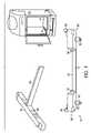
図1を参照すると、ステージングアセンブリ10が、撮像チャンバ14を含む撮像マシン12で使用するために示されている。ステージングアセンブリ10は、標本、たとえばマウスまたはラットに麻酔を搬送する役割を果たすマニホルドアセンブリ16と、マニホルドアセンブリ16が取り付けられたステージングドック18と、を含んでいる。以下により詳細に記載するように、外部の供給源からの麻酔は、ステージングドック18を通してマニホルドアセンブリ16に搬送される。ステージングドック18とマニホルドアセンブリ16との両方は、撮像チャンバ14に配置される。麻酔は、マニホルドアセンブリ16を通して、撮像チャンバ14内に配置された1つまたは複数の標本に分配される。標本の撮像は、撮像マシン12によって実施される。残った麻酔ガスは、撮像マシン12に組み込まれているか、撮像マシン12の外部にある排気システムにより、マニホルドアセンブリ16から、次いでステージングドック18を通して、撮像マシン12の外部に排出される。特定の実施形態では、撮像マシン12は、残った麻酔を、マニホルドアセンブリ16から、次いで撮像マシン12の外部に吸い出すための吸引システムを含む場合がある。 Referring to FIG. 1, staging
特定の実施形態では、ステージングドック18は、以下により詳細に図示及び記載される一対の後退可能なピン20を含む場合がある。このピン20は、撮像チャンバ14の底部に形成されたアパーチャ22に受領される。アパーチャ22内のピン20の係合により、ステージングドック18が、繰り返し可能な位置において撮像チャンバ14に対して固定されることが確実になり、標本に関して取られる連続した画像の正確さを向上させる助けになる。特定の実施形態では、撮像チャンバ14は、2つの対向するアパーチャ22の列を含むことができ、ステージングドック18を撮像チャンバ14内で異なる決まった位置に配置することを可能にする。 In certain embodiments, staging
ステージングドック18は、ベース19と、ステージングドック麻酔流入口24と、を含んでいる。ステージングドック麻酔流入口24は、撮像チャンバ14内のチューブまたは導管(図示せず)または任意の他の適切なタイプのコネクタから麻酔を受領する。麻酔は、ベース19を通ってステージングドック麻酔流出口26に移動する。ステージングドック麻酔流出口26は、マニホルドアセンブリ16がステージングドック18と係合する際に、マニホルドアセンブリ16の流入開口28(図2で以下に記載する)によって受領される。ステージングドック麻酔流出口26は、以下により詳細に図示及び記載されるバルブ30を含んでいる。したがって、麻酔は、ステージングドック18内にステージングドック麻酔流入口24を通って移動し、ステージングドック18を出てステージングドック麻酔流出口26を通り、次いで、マニホルドアセンブリ16の流入開口28に入る。
ステージングドック18は、ステージングドック排出流入口32を含んでいる。ステージングドック排出流入口32は、マニホルドアセンブリ16がステージングドック18と係合する際に、マニホルドアセンブリ16の流出開口34(図2で以下に記載する)によって受領される。ステージングドック18は、ステージングドック排出流出口36をも含んでいる。ステージングドック排出流出口36は、撮像チャンバ14内のチューブまたは導管(図1には図示せず)または任意の他の適切なタイプのコネクタに接続されている。残った麻酔ガスは、マニホルドアセンブリ16の流出開口34を通ってマニホルドアセンブリ16から排出され、次いで、ステージングドック排出流入口32を通ってステージングドック18に入る。残った麻酔ガスは、次いで、ステージングドック排出流出口36を通ってステージングドック18を出て、その後に撮像チャンバ14のコネクタを通って外部または撮像マシン12に出る。
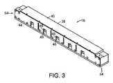
図2から図4に示すように、マニホルドアセンブリ16はハウジング38を含んでいる。上述のように、ハウジング38は、マニホルドアセンブリ16がステージングドック18と係合した際に、ステージングドック麻酔流出口30を受領する流入開口28と、ステージングドック排出流入口32を受領する流出開口34と、を含んでいる。 As shown in FIGS. 2-4,
ハウジング38は、流入開口28及び流出開口34が形成されたマニホルド40と、底部プレート42と、前部プレート44とを含む場合がある。ハウジング38のすべての要素、及び、ステージングアセンブリ10の他のパーツが、撮像マシン12の撮像システムがx線システムである場合の干渉を防止するように、非金属材料で形成される場合があることを理解されたい。さらに、ハウジング38のすべての要素、及び、ステージングアセンブリ10の他のパーツは、E.I. du Pont de Nemours and Company of Wilmington, DEからDelrin(登録商標)として利用可能な、ポリオキシメチレンなどの放射線透過性の熱可塑性物質で形成されている場合がある。
さらに、ステージングアセンブリ10の要素のすべてが、反射性を低減させ、撮像チャンバ12の良好な画像の生成を補助するために、黒色、非反射性、及び/または非蛍光性である場合があることを理解されたい。 Further, all of the elements of staging
複数のチャンバ46は、マニホルド40内に形成されており、各チャンバは、前部プレート44に形成された開口48を有している。チャンバ46は、流入開口28及び流出開口34と流体連通しており、それにより、麻酔が、チャンバ46内に流入し、また、残った麻酔がチャンバ46の外に流出することを可能にする。開口48は、マウスまたはラットなどの標本の鼻先の少なくとも一部を受領するように構成及びサイズ設定されている。 A plurality of
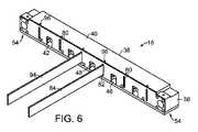
特定の実施形態では、マニホルドアセンブリ16は、図4により明確に示すマニホルド取付けアセンブリ54を含む場合がある。図4では、マニホルドアセンブリ16が分解された形態で示されている。マニホルド取付けアセンブリ54は、図1に示すステージングドック取付けアセンブリ56と関連して作用して、マニホルドアセンブリ16をステージングドック18に取外し可能に固定する。特定の実施形態では、マニホルド取付けアセンブリ54とステージングドック取付けアセンブリ56とは、マニホルドアセンブリ16をステージングドック18に固定するために磁石を使用する場合がある。 In certain embodiments,
図示の実施形態では、磁石ブロック58が、マニホルド40の端部で前部プレート44及び底部プレート42に固定されている。磁石60は、磁石ブロック58に形成されたアパーチャ62内に着座されている。フォームプラグ64は、磁石60の外に向くように、アパーチャ62に挿入されている場合がある。磁石ブロック58は、ネジ65によって前部プレート44及び底部プレート42に固定されている場合がある。 In the illustrated embodiment, magnet blocks 58 are secured to
特定の実施形態では、磁石ブロック58は、たとえば、アルミニウムなどの金属で形成されている。磁石60は、たとえばネオジムで形成されている場合がある。磁石ブロック58及び磁石60に適切な他の材料は、本開示の利益が与えられると、当業者には容易に明らかとなるであろう。 In certain embodiments,
特定の実施形態では、ステージングドック取付けアセンブリ56は、磁石60の極性とは逆の極性に向けられた磁石をも含む場合がある。他の実施形態では、ステージングドック取付けアセンブリ56は、磁石60を取外し可能に固定することができる磁石または鉄材料の片を単に含む場合がある。特定の実施形態では、ステージングドック取付けアセンブリ56は、磁石60を含むことができ、一方、マニホルド取付けアセンブリ54は、磁性であるか鉄の材料片を単に含むことができる。このため、マニホルド取付けアセンブリ54とステージングドック取付けアセンブリ56との少なくとも一方は、磁石を含んでいる。 In certain embodiments, staging
底部プレート42及び前部プレート44は、ボルトまたはネジ66または他の適切な締結具でマニホルド40に固定されている場合がある。ネジ66は、たとえば、ナイロンなどの放射線透過性材料で形成されている場合がある。
図5により詳細に見られるように、マニホルド40は、流入開口28と流体連通している流入導管68を含んでいる。複数のチャンバ流入導管70が、流入導管68と流体連通している。各チャンバ46は、その頂部にチャンバ流入口72を有している。チャンバ流入口72は、チャンバ流入導管70の1つと流体連通している。 As seen in more detail in FIG. 5,
このため、麻酔は、矢印Aの方向にマニホルド40の流入開口28に入り、矢印Bの方向に流入導管68を通り、矢印Cの方向にチャンバ流入導管70を通り、次いで矢印Dの方向にチャンバ流入口72を通ってチャンバ46内に下方に流れることができる。 Thus, anesthesia enters inlet opening 28 of
マニホルド40は、流出開口34と流体連通している流出導管74をも含んでいる。複数のチャンバ流出導管76が、流出導管74と流体連通している。各チャンバ46は、一対のチャンバ流出口78を有しており、チャンバ流出口78の各々は、チャンバ流出導管76の1つと流体連通している。図示の実施形態では、各チャンバ流出口78は、チャンバ46の底部に、その一方側で配置されている。
このため、残った麻酔は、矢印Eの方向に、チャンバ46のチャンバ流出口78を出てチャンバ流出導管76に入り、矢印Fの方向に流出導管74を通り、次いで、矢印Gの方向に流出開口34を通ってマニホルド40を出るように流れることができる。特定の実施形態では、持続的な吸引状態が、残った麻酔が継続的にチャンバ46から排出されることを確実にするために、マニホルド40内に維持されている。 Thus, residual anesthesia exits
この構成により、麻酔が標本へ効率的に搬送され、この標本の鼻先が、チャンバ46内へ、開口48を通して配置され、また、残った麻酔がチャンバ46から効率的に排出され、それにより、ユーザが麻酔に曝される可能性が低減される。 This configuration effectively delivers anesthesia to the specimen, positions the nose tip of the specimen into
特定の実施形態では、マニホルド40は、材料の固形ブロックであり、流入導管68、チャンバ流入導管70、チャンバ流入口72、チャンバ流出導管76、流出導管74、及び流出開口34は、マニホルド40に開けられた穴である。マニホルド40は、必ずしも固形ブロックとして形成される必要はなく、様々な導管及び流入口を、互いに接続される、パイプまたはチューブなどの別々の部材とすることができることを理解されたい。 In certain embodiments,
導管がマニホルド40の穴であるそのような実施形態では、プラグ79が、図4及び図5に示すように、流入導管68、流出導管74、及びチャンバ流入導管70の端部に挿入される場合がある。特定の実施形態では、プラグ79は止めネジである場合がある。プラグ79は、たとえば、ナイロンなどの放射線透過性材料、またはステンレス鋼で形成されている場合がある。 In such embodiments where the conduits are holes in
図6に示すように、複数のアパーチャまたはスロット80が、前部プレート44に形成されている。1つまたは複数のバッフル84の各々の第1の端部82は、スロット80の1つに受領されている場合がある。バッフル84は、標本が撮像チャンバ14内に配置された際に、標本を互いから分ける役割を果たし、標本のそれぞれの各鼻先が、前部プレート44に形成されたチャンバ開口48の1つに受領されている。 A plurality of apertures or
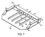
特定の実施形態では、図7及び図8に示すように、底部プレート42は、ステージングトレー86を形成するように、マニホルド40から外向きに延びている場合があり、バッフル84は、底部プレート42に沿って延びるとともに、底部プレート42上に着座されている場合がある。図8は、ステージングドック18とのその係合された位置のステージングトレーを示している。 In certain embodiments, as shown in FIGS. 7 and 8, the
ステージングトレー86は、標本を撮像チャンバ14に配置することを必要とする前に、撮像のためにユーザが標本を準備することを可能にする。このため、標本の第1のセットが撮像チャンバ14内に配置されている間、標本の第2のセットは、ステージングトレー86上に適切な位置に配置され得る。標本の第1のセットの撮像が完了し、その標本のセットが撮像チャンバ14から除かれた後に、標本の第2のセットを伴うステージングトレー86を、上述のように、撮像チャンバ14のステージングドック18に固定することができる。
だぼまたはピン88の複数の対が、底部プレート42から上方に延びている場合があり、各バッフルは、ピン88の1つの対の各ピン88間に配置されるとともに、各ピン88に当接している。ピン88は、バッフル84を、ステージングトレー86上で整列され、適切な位置にあるように維持する役割を果たす。特定の実施形態では、ピン88は、たとえば、ステンレス鋼などの金属で形成されている。ピン88は、反射性を低減し、良好な画像を提供することを補助するように、黒く不動態化されたステンレス鋼である場合がある。 A plurality of pairs of dowels or pins 88 may extend upwardly from the
図示の実施形態では、4つのバッフル84が、ステージングトレー86に沿って配置され、5つの標本をステージングトレー86上で適切な位置に配置することを可能にする。4より多いか少ないバッフル84が、ステージングトレー86に沿って配置され得ることを理解されたい。 In the illustrated embodiment, four
特定の実施形態では、ステージングトレー86は、このステージングトレー86にネジ留めされるか、溶接されるか、接着されるか、ボルト留めされるか、別様に固定された一対のハンドル90を含む場合がある。各ハンドル90の第1の端部92は、磁石ブロック58に固定されている場合があり、一方、各ハンドル90の第2の端部94は、底部プレート42に固定されている場合がある。特定の実施形態では、ハンドル90は、たとえば、アルミニウムなどの金属で形成されており、黒色に陽極処理されている場合がある。特定の実施形態では、第2の端部94は、第1の端部92に固定された別の材料片である場合があり、E.I. du Pont de Nemours and Company of Wilmington, DEからDelrin(登録商標)として利用可能な、ポリオキシメチレンなどの黒色の熱可塑性物質で形成されている場合がある。 In certain embodiments, the staging
特定の実施形態では、複数の基準要素96が、マニホルド40の頂部表面に沿って配置されている。基準要素96は、撮像マシン12内のステージングトレー86及び標本の配置のための基準ポイントとしての役割を果たす。 In certain embodiments, a plurality of
図9に示すように、ステージングアセンブリ10は、ポージングステーション98をも含む場合がある。ポージングステーション98は、トレー100及びポージングステーションステージングドック102を含む場合がある。ポージングステーションステージングドック102は、このポージングステーションステージングドック102が同じ方式で動作することから、ステージングドック18の構成要素と同じ構成要素を有している。しかし、ポージングステーションステージングドック102は、撮像マシン12の麻酔供給源及び真空源に接続されていないが、むしろ外部の麻酔供給源及び外部の真空源に接続されている。さらに、ポージングステーションステージングドック102が撮像マシン12内に配置されていないことから、図9に示す実施形態に見られるように、後退可能なピン20を必ずしも含んでいない。 As shown in FIG. 9, staging
いくつかの実施形態では、トレー100は、標本が麻酔下にある間、標本に関する適切な本体温度を維持するように加熱される場合がある。特定の実施形態では、トレー100は、標本の本体温度がおおむね37℃±2℃に維持されるように加熱される場合がある。 In some embodiments, the
ステージングトレー86は、標本を撮像マシン12内に配置する前に、標本を適切な位置に配置するか、位置決めするために、ポージングステーションステージングドック102に接続することができる。これにより、ユーザがステージングトレー86内で標本を適切に配置または位置決めすることができ、標本の別のセットが撮像マシン12で撮像をされている間、標本を麻酔された状態に維持できることから、処理量を増大させることができる。撮像マシン12内の標本の撮像が完了すると、ステージングトレー86は、ポージングステーション98から接続解除することができ、また、ステージングトレー86上の標本の画像を提供するために、撮像マシン12のステージングドック18に接続することができる。 A staging
ステージングアセンブリ10が、標本を適切に位置決め及び準備するために、複数のステージングトレー86を含むことができることを理解されたい。このことは、これによって待機時間が低減されるか無くなることから、処理量を増大させる。 It should be appreciated that the staging
バルブ30を伴うステージングドック麻酔流出口26の実施形態が、図10及び図11に示されている。以下により詳細に記載するように、バルブ30は、図10においてその閉じた位置で示され、図11においてその開いた位置で示されており、バルブ30が、ステージングドック18と係合した状態で見られる。 An embodiment of staging
バルブ30は、バルブ本体104を含む場合がある。このバルブ本体104は、図11に見られるように、マニホルドアセンブリ16の流入開口28内に受領されている。Oリング106が、バルブ本体104と流入開口28との間をシールして係合させるように、バルブ本体104の外部表面に形成された溝108に設けられている場合がある。特定の実施形態では、Oリングは、ステージングドック排出流入口32の外部にも設けられている場合がある。
ステージングドック18に形成されたキャビティ110は、ステージングドック18の麻酔流入口24と流体連通している。バルブ本体104は、キャビティ110と流体連通している筒状開口112を含んでいる。バルブ本体104に形成されたアパーチャ114は、筒状開口112及びバルブ本体104の外部と流体連通している。このため、流路は、麻酔流入口24からキャビティ110、筒状開口112、アパーチャ114、及び流入開口28を通って形成されており、麻酔が麻酔供給源からバルブ30を通ってステージングドック18内に流れることを可能にしている。 A
バルブ30は、第1の端部及び第2の端部を有するシャフト116を含んでいる。このシャフト116は、筒状開口112内に移動可能に受領されており、かつ、シャフト116と筒状開口112との間に隙間118を規定している。キャップ117が、たとえばこのキャップ117とシャフト116との間のネジ山による係合などにより、シャフト116の第2の端部に固定されている。ベアリング119は、シャフト116の第2の端部と、バルブ本体104の外側端部との間の隙間118に着座されている場合があり、それにより、シャフト116とキャップ117との中心付けを補助している。ベアリング119は、たとえば、ナイロンなどの低摩擦材料で形成されている場合がある。
プラグ120は、キャビティ110内に着座されており、かつ、ネジまたはシーリングネジ122により、シャフト116の第1の端部に固定されている。シーリングネジ122は、漏洩を低減するために、Oリング(図示せず)を含む場合がある。ガスケット124などのシーリング部材は、プラグ120と隙間118との間で、キャビティ110内に着座されている。バネ126は、キャビティ110内に着座され、バルブ30が、図10に示すような閉じた状態にある際に、ガスケット124とシール係合するように、プラグ120にバイアスをかけている。特定の実施形態では、バネ126は、円錐型バネである場合がある。 A
図11に示すように、マニホルドアセンブリ16がステージングドック18と係合した場合、キャップ117は、流入開口28の内側表面と係合し、それにより、キャップ117、シャフト116、プラグ120、及びシーリングネジ122を、バネ126のバイアスの圧力に抗して押し下げ、プラグ120を、ガスケット124とのシール係合から外すように移動させる。ここで、矢印Mによって示すように、流入開口28からキャビティ110内へ、隙間118を通って上昇し、アパーチャ114を出て流入開口28内に、また、流入導管68に、麻酔が流れる明確な経路が存在する。 As shown in FIG. 11, when
本開示から得られた知識により、当業者は、本開示の範囲から逸脱することなく、これら及び他の利点を得る中で、開示の装置及び方法に様々な変更を行うことができることを理解するであろう。したがって、本明細書に記載の特徴は、変更、修正、変化、または代替の余地があることを理解されたい。たとえば、同じ結果を達成するために、実質的に同じ機能を、実質的に同じ方法で実施するこれら要素及び/またはステップのすべての組合せが、本明細書に記載の実施形態の範囲内にあることが、明確に意図されている。ある記載の実施形態からの要素を、別の要素と代替することも、完全に意図されるとともに、考慮される。本明細書で図示及び記載される特定の実施形態は、もっぱら説明の目的のためのものであり、添付の特許請求の範囲に説明されているものを限定するものではない。他の実施形態が、当業者には明らかとなるであろう。前述の記載が、明確化のみのために提供され、単に例示的ものであることを理解されたい。本開示の精神及び範囲は、上述の実施例には限定されないが、添付の特許請求の範囲によって包含される。上述の刊行物及び特許出願のすべては、個別の刊行物または特許出願の各々が、参照することによってそのように組み込まれるように明確かつ個別に示されたかのような範囲と同じ範囲まで、すべての目的に関し、その全体が、参照することによって組み込まれる。 With knowledge gained from this disclosure, those skilled in the art will understand that various modifications can be made to the disclosed apparatus and methods while still obtaining these and other advantages without departing from the scope of this disclosure. Will. Therefore, it should be understood that the features described herein are susceptible to alteration, modification, variation or substitution. For example, all combinations of those elements and/or steps that perform substantially the same function in substantially the same way to achieve the same results are within the scope of the embodiments described herein. is clearly intended. Substitutions of elements from one described embodiment for another are also fully intended and contemplated. The specific embodiments shown and described herein are for illustrative purposes only and are not limiting of what is set forth in the appended claims. Other embodiments will be apparent to those skilled in the art. It should be understood that the foregoing description is provided for clarity only and is exemplary only. The spirit and scope of this disclosure are not limited to the above-described examples, but are encompassed by the following claims. All of the above-mentioned publications and patent applications are expressly incorporated herein by reference to the same extent as if each individual publication or patent application were expressly and individually indicated to be so incorporated by reference. for purposes, the entirety of which is incorporated by reference.
Claims (25)
Translated fromJapaneseステージングドックと、
を備えた標本撮像マシンのためのステージングアセンブリであって、
前記マニホルドアセンブリが、
流入開口及び流出開口を有するハウジング、
複数のチャンバであって、各チャンバがチャンバ開口を有する、前記複数のチャンバ、
前記チャンバを前記流入開口及び前記流出開口と流体連通させる複数の導管、
前記チャンバの各々の下に延びる底部プレート、ならびに、
マニホルド取付けアセンブリ、
を備え、
前記ステージングドックが、
ベース、
ステージングドック麻酔流入口、
前記マニホルドアセンブリの前記流入開口によって受領可能であり、バルブを含むステージングドック麻酔流出口であって、麻酔は、前記ステージングドック麻酔流入口を通って前記ステージングドック内に移動し、前記ベースを通って移動し、前記ステージングドック麻酔流出口を通って前記ステージングドック外に移動し、次いで、前記マニホルドアセンブリの前記流入開口内に移動する、前記ステージングドック麻酔流出口、
前記マニホルドアセンブリの前記流出開口によって受領可能であるステージングドック排出流入口、
ステージングドック排出流出口であって、前記マニホルドアセンブリから排出される残った麻酔は、前記ステージングドック排出流入口を通って前記ステージングドック内に移動し、前記ステージングドック排出流出口を通って前記ステージングドックから出る、前記ステージングドック排出流出口、及び、
前記マニホルド取付けアセンブリに取外し可能に取付け可能なステージングドック取付けアセンブリ、
を備える、ステージングアセンブリ。a manifold assembly;
a staging dock;
A staging assembly for a specimen imaging machine comprising:
the manifold assembly comprising:
a housing having an inflow opening and an outflow opening;
a plurality of chambers, each chamber having a chamber opening;
a plurality of conduits placing the chamber in fluid communication with the inflow opening and the outflow opening;
a bottom plate extending under each of said chambers; and
manifold mounting assembly,
with
The staging dock
base,
staging dock anesthesia inlet,
a staging dock anesthesia outlet receivable by the inlet opening of the manifold assembly and including a valve, wherein anesthesia travels into the staging dock through the staging dock anesthesia inlet and through the base; said staging dock anesthesia outlet moving out of said staging dock through said staging dock anesthesia outlet and then into said inlet opening of said manifold assembly ;
a staging dock discharge inlet receivable by the outlet opening of the manifold assembly;
a staging dock discharge outletwherein residual anesthesia discharged from the manifold assembly travels into the staging dock through the staging dock discharge inlet and into the staging dock through the staging dock discharge outlet; the staging dock discharge outlet , and
a staging dock mounting assembly removably attachable to said manifold mounting assembly;
a staging assembly.
前記ポージングステーションが、
ポージングトレーと、
ポージングステーション麻酔流入口と、
前記マニホルドアセンブリの前記流入開口によって受領可能であり、バルブを含むポージングステーション麻酔流出口であって、麻酔は、前記ポージングステーション麻酔流入口を通って前記ポージングステーション内に移動し、前記ポージングステーション麻酔流出口を通って前記ポージングステーション外に移動し、次いで、前記マニホルドアセンブリの前記流入開口内に移動し、前記ポージングトレーは、標本が前記麻酔下にある間において前記標本に関する本体温度を維持するように加熱されるように構成される、前記ポージングステーション麻酔流出口と、
前記マニホルドアセンブリの前記流出開口によって受領可能であるポージングステーション排出流入口と、
ポージングステーション排出流出口であって、前記マニホルドアセンブリから排出される残った麻酔は、前記ポージングステーション排出流入口を通って前記ポージングステーション内に移動し、前記ポージングステーション排出流出口を通って前記ポージングステーションから出る、前記ポージングステーション排出流出口と、
前記マニホルド取付けアセンブリに取外し可能に取付け可能なポージングステーション取付けアセンブリと、
を備える、請求項1に記載のステージングアセンブリ。Equipped with a posing station,
The posing station
a posing tray;
a posing station anesthesia inlet;
A posing station anesthetic outlet receivable by the inlet opening of the manifold assembly and including a valve, wherein anesthesia travels into the posing station through the posing station anesthetic inlet and into the posing station anesthetic flow. Out of the posing station through an exit and into the inlet opening of the manifold assembly, the posing tray so as to maintain a body temperature for the specimen while it is under the anesthesia. the posing station anesthetic outlet configured to be heated ;
a posing station exhaust inlet receivable by the outlet opening of the manifold assembly;
a posing station discharge outletwherein residual anesthesia discharged from the manifold assembly travels into the posing station through the posing station discharge inlet and into the posing station through the posing station discharge outlet; said posing station discharge outlet exiting from ;
a posing station mounting assembly removably attachable to the manifold mounting assembly;
2. The staging assembly of claim 1,comprising :
バルブ本体であって、前記ステージングドックの前記ベースに形成されたキャビティと流体連通する筒状開口であって、前記キャビティが、前記麻酔流入口と流体連通している、前記筒状開口、ならびに、前記筒状開口及び前記バルブ本体の外部と流体連通するアパーチャを含む、前記バルブ本体と、
シャフトであって、前記シャフトと前記筒状開口との間に隙間を画定するように、前記筒状開口内に移動可能に受領される前記シャフト、及び、前記シャフトの第1の端部にあり、前記キャビティ内に移動可能に受領されるプラグと、
前記キャビティ内に着座し、前記プラグを前記隙間に向けて付勢するバネと、
前記プラグと前記隙間との間に配置されたシーリング部材と、
を備える、請求項1に記載のステージングアセンブリ。the valve
a valve body, a tubular opening in fluid communication with a cavity formed in the base of the staging dock, the cavity being in fluid communication with the anesthesia inlet; and the valve body including an aperture in fluid communication with the tubular opening and the exterior of the valve body;
a shaft movably received within the tubular opening to define a gap between the shaft and the tubular opening; and at a first end of the shaft. , a plug movably received within the cavity;
a spring seated within the cavity and biasing the plug toward the gap;
a sealing member disposed between the plug and the gap;
2. The staging assembly of claim 1, comprising:
ステージングドックと、
を備える動物撮像マシンのためのステージングアセンブリであって、
前記マニホルドアセンブリが、
流入開口、前記流入開口と流体連通する流入導管、前記流入導管と流体連通する複数のチャンバ流入導管、流出開口、前記流出開口と流体連通する流出導管、及び、前記流出導管と流体連通する複数のチャンバ流出導管を有するハウジング、
複数のチャンバであって、各チャンバが、前記チャンバの頂部にあり、前記チャンバ流入導管の1つと流体連通するチャンバ流入口、チャンバ開口、及び、一対のチャンバ流出口であって、各チャンバ流出口が、前記チャンバの一方側かつ底部に配置され、前記チャンバと前記チャンバ流出導管の1つとの間に延びる、前記一対のチャンバ流出口を含む、前記複数のチャンバ、
前記チャンバ開口を画定する前部プレート、
前記チャンバの各々の下に延びる底部プレート、
マニホルド取付けアセンブリ、ならびに、
前記ハウジングに取外し可能に固定された複数のバッフルであって、各バッフルが、隣接するチャンバ開口間に配置されている、前記複数のバッフル、
を備え、
前記ステージングドックが、
ベース、
麻酔流入口、
前記マニホルドアセンブリの前記流入開口によって受領可能であり、バルブを含むマニホルド流出口であって、麻酔は、前記麻酔流入口を通って前記ステージングドック内に移動し、前記ベースを通って移動し、前記マニホルド流出口を通って前記ステージングドック外に移動し、次いで、前記マニホルドアセンブリの前記流入開口内に移動する、前記マニホルド流出口、
前記マニホルドアセンブリの前記流出開口によって受領可能である排出流入口、
排出流出口であって、前記マニホルドアセンブリから排出される残った麻酔は、前記排出流入口を通って前記ステージングドック内に移動し、前記排出流出口を通って前記ステージングドックから出る、前記排出流出口、及び、
前記マニホルド取付けアセンブリに取外し可能に取付け可能なステージングドック取付けアセンブリ、
を備える、ステージングアセンブリ。a manifold assembly;
a staging dock;
A staging assembly for an animal imaging machine comprising:
the manifold assembly comprising:
an inlet opening, an inlet conduit in fluid communication with the inlet opening, a plurality of chamber inlet conduits in fluid communication with the inlet conduit, an outlet opening, an outlet conduit in fluid communication with the outlet opening, and a plurality of outlet conduits in fluid communication. a housing having a chamber outflow conduit;
a plurality of chambers, each chamber at the top of said chamber and in fluid communication with one of said chamber inlet conduits, a chamber inlet, a chamber opening and a pair of chamber outlets, each chamber outlet; said plurality of chambers including said pair of chamber outlets disposed on one side and bottom of said chambers and extending between said chambers and one of said chamber outlet conduits;
a front plate defining the chamber opening;
a bottom plate extending under each of said chambers;
a manifold mounting assembly, and
a plurality of baffles removably secured to the housing, each baffle positioned between adjacent chamber openings;
with
The staging dock
base,
anesthesia inlet,
A manifold outlet receivable by the inlet opening of the manifold assembly and including a valve, wherein anesthesia travels through the anesthesia inlet into the staging dock, travels through the base, and said manifold outlet moving out of said staging dock through a manifold outlet and then into said inlet opening of said manifold assembly ;
an exhaust inlet receivable by the outlet opening of the manifold assembly;
a discharge outlet, wherein residual anesthesia discharged from the manifold assembly travels into the staging dock through the discharge inlet and exits the staging dock through the discharge outlet; exit , and
a staging dock mounting assembly removably attachable to said manifold mounting assembly;
a staging assembly.
25. The staging assembly of Claim 24, wherein at least some of said screws are formed of a radiolucent material.
Applications Claiming Priority (3)
| Application Number | Priority Date | Filing Date | Title |
|---|---|---|---|
| US16/053,134 | 2018-08-02 | ||
| US16/053,134US11179233B2 (en) | 2018-08-02 | 2018-08-02 | Staging assembly for specimen imaging system |
| PCT/US2019/043215WO2020028114A1 (en) | 2018-08-02 | 2019-07-24 | Staging assembly for specimen imaging system |
Publications (2)
| Publication Number | Publication Date |
|---|---|
| JP2021532901A JP2021532901A (en) | 2021-12-02 |
| JP7118241B2true JP7118241B2 (en) | 2022-08-15 |
Family
ID=67809644
Family Applications (1)
| Application Number | Title | Priority Date | Filing Date |
|---|---|---|---|
| JP2021505678AActiveJP7118241B2 (en) | 2018-08-02 | 2019-07-24 | Staging assembly for specimen imaging system |
Country Status (6)
| Country | Link |
|---|---|
| US (1) | US11179233B2 (en) |
| EP (1) | EP3829484A1 (en) |
| JP (1) | JP7118241B2 (en) |
| CN (1) | CN112601505B (en) |
| AU (1) | AU2019313271B2 (en) |
| WO (1) | WO2020028114A1 (en) |
Families Citing this family (1)
| Publication number | Priority date | Publication date | Assignee | Title |
|---|---|---|---|---|
| KR102546417B1 (en)* | 2021-03-02 | 2023-06-22 | 주식회사 뷰웍스 | Anesthetic gas distribution device |
Citations (4)
| Publication number | Priority date | Publication date | Assignee | Title |
|---|---|---|---|---|
| JP2005517507A (en) | 2002-02-20 | 2005-06-16 | ゼノジェン コーポレイション | Multiple output anesthesia system |
| JP2008012095A (en) | 2006-07-06 | 2008-01-24 | Olympus Corp | Somatoscopic apparatus |
| JP2009082448A (en) | 2007-09-28 | 2009-04-23 | Fujifilm Corp | Nose mask |
| US20150047724A1 (en) | 2013-08-19 | 2015-02-19 | University Of Notre Dame Du Lac | Fluid manifold |
Family Cites Families (12)
| Publication number | Priority date | Publication date | Assignee | Title |
|---|---|---|---|---|
| CA2164034C (en)* | 1995-11-29 | 2003-04-29 | Renaud Vincent | Respiratory nose-only device and system for laboratory animals |
| US6776158B1 (en)* | 2001-07-26 | 2004-08-17 | Euthanex Corporation | System for anesthetizing laboratory animals |
| US6878938B2 (en)* | 2003-07-16 | 2005-04-12 | Perkinelmer, Inc. | High frequency infrared radiation source |
| US7734325B2 (en)* | 2004-09-21 | 2010-06-08 | Carestream Health, Inc. | Apparatus and method for multi-modal imaging |
| US9446212B2 (en)* | 2009-08-03 | 2016-09-20 | Colin Dunlop | Method and apparatus for delivering a fluid to a patient |
| US8388736B2 (en)* | 2009-10-02 | 2013-03-05 | Perkinelmer Health Sciences, Inc. | Sorbent devices and methods of using them |
| JP2014502760A (en)* | 2010-12-30 | 2014-02-03 | パーキンエルマー シンガポール ピーティーイー エルティーディー | Hollow cathode lamp elapsed time recording system |
| US9078451B2 (en)* | 2013-03-01 | 2015-07-14 | Brian Stevens | Method for euthanizing animals |
| EP3300758B1 (en)* | 2013-03-15 | 2019-05-29 | Airway Control Technologies, LLC | Medical breathing apparatus |
| CN203598075U (en)* | 2013-12-09 | 2014-05-21 | 杨小霖 | Inhalation anesthesia device for experiment animals |
| CN103976804A (en)* | 2014-04-11 | 2014-08-13 | 广州医科大学附属第一医院 | Mouse anesthesia apparatus |
| US20170312066A1 (en)* | 2015-11-30 | 2017-11-02 | The University Of Notre Dame Du Lac | Versatile inhalation anesthesia platform for small animal surgery |
- 2018
- 2018-08-02USUS16/053,134patent/US11179233B2/enactiveActive
- 2019
- 2019-07-24JPJP2021505678Apatent/JP7118241B2/enactiveActive
- 2019-07-24EPEP19761982.8Apatent/EP3829484A1/enactivePending
- 2019-07-24AUAU2019313271Apatent/AU2019313271B2/enactiveActive
- 2019-07-24WOPCT/US2019/043215patent/WO2020028114A1/ennot_activeCeased
- 2019-07-24CNCN201980055468.1Apatent/CN112601505B/enactiveActive
Patent Citations (4)
| Publication number | Priority date | Publication date | Assignee | Title |
|---|---|---|---|---|
| JP2005517507A (en) | 2002-02-20 | 2005-06-16 | ゼノジェン コーポレイション | Multiple output anesthesia system |
| JP2008012095A (en) | 2006-07-06 | 2008-01-24 | Olympus Corp | Somatoscopic apparatus |
| JP2009082448A (en) | 2007-09-28 | 2009-04-23 | Fujifilm Corp | Nose mask |
| US20150047724A1 (en) | 2013-08-19 | 2015-02-19 | University Of Notre Dame Du Lac | Fluid manifold |
Also Published As
| Publication number | Publication date |
|---|---|
| CN112601505B (en) | 2024-07-23 |
| EP3829484A1 (en) | 2021-06-09 |
| US20200038163A1 (en) | 2020-02-06 |
| AU2019313271B2 (en) | 2025-02-27 |
| US11179233B2 (en) | 2021-11-23 |
| WO2020028114A1 (en) | 2020-02-06 |
| JP2021532901A (en) | 2021-12-02 |
| AU2019313271A1 (en) | 2021-03-11 |
| WO2020028114A8 (en) | 2021-02-25 |
| CN112601505A (en) | 2021-04-02 |
Similar Documents
| Publication | Publication Date | Title |
|---|---|---|
| JP7118241B2 (en) | Staging assembly for specimen imaging system | |
| US8774899B2 (en) | Specimen positioning system for imaging machines | |
| US7774972B2 (en) | Modular shooting rests and shooting rest assemblies | |
| CN105937542A (en) | Override for an automatic release vacuum device | |
| US7073442B2 (en) | Apparatus, systems and methods for use in three-dimensional printing | |
| CN109642880B (en) | Modular sample holder for high pressure freezing of samples and X-ray crystallography | |
| US7534067B2 (en) | Coupling assembly for animal management systems | |
| US9527182B2 (en) | Device for the extraction, parallel to the process, of processing products arising during the processing of a workpiece | |
| BR102016015757A2 (en) | methods and apparatus for manipulating stamping rings | |
| US10947998B2 (en) | Fluid pressure cylinder | |
| US20120172185A1 (en) | Tool magazine device for a machine tool | |
| SE429249B (en) | WELDING DEVICE INTENDED TO BE APPLIED ON A RUDE SUPPLY SUPPLIED WITH BAJONET LOADER | |
| JP6594380B2 (en) | Front loading valve assembly for manifold for processing fluid samples | |
| TWI353450B (en) | Syringe block for automatic machine for analysis o | |
| KR20080014837A (en) | Exhaust gas dilution unit | |
| US8141468B2 (en) | Adjustable bomb carrier | |
| CN217133120U (en) | A special pesticide residue detection device for edible agricultural products | |
| CN120290281A (en) | Single cell operation device | |
| US11810797B2 (en) | Wetting processing apparatus and operation method thereof | |
| US20170184135A1 (en) | Hydraulic connection having a flexible port mouth and method for connecting same | |
| KR102474872B1 (en) | Gripper Module | |
| KR102546417B1 (en) | Anesthetic gas distribution device | |
| CN210487782U (en) | Methylene chloride dipping tester | |
| CN117344290B (en) | Graphite crucible and chemical vapor deposition equipment | |
| JP3407127B2 (en) | Micro injector |
Legal Events
| Date | Code | Title | Description |
|---|---|---|---|
| A621 | Written request for application examination | Free format text:JAPANESE INTERMEDIATE CODE: A621 Effective date:20210215 | |
| A131 | Notification of reasons for refusal | Free format text:JAPANESE INTERMEDIATE CODE: A131 Effective date:20220302 | |
| A521 | Request for written amendment filed | Free format text:JAPANESE INTERMEDIATE CODE: A523 Effective date:20220525 | |
| TRDD | Decision of grant or rejection written | ||
| A01 | Written decision to grant a patent or to grant a registration (utility model) | Free format text:JAPANESE INTERMEDIATE CODE: A01 Effective date:20220704 | |
| A61 | First payment of annual fees (during grant procedure) | Free format text:JAPANESE INTERMEDIATE CODE: A61 Effective date:20220802 | |
| R150 | Certificate of patent or registration of utility model | Ref document number:7118241 Country of ref document:JP Free format text:JAPANESE INTERMEDIATE CODE: R150 | |
| S531 | Written request for registration of change of domicile | Free format text:JAPANESE INTERMEDIATE CODE: R313531 | |
| S533 | Written request for registration of change of name | Free format text:JAPANESE INTERMEDIATE CODE: R313533 | |
| R350 | Written notification of registration of transfer | Free format text:JAPANESE INTERMEDIATE CODE: R350 | |
| R250 | Receipt of annual fees | Free format text:JAPANESE INTERMEDIATE CODE: R250 |