JP7117060B2 - Reference station display system - Google Patents
Reference station display systemDownload PDFInfo
- Publication number
- JP7117060B2 JP7117060B2JP2019006580AJP2019006580AJP7117060B2JP 7117060 B2JP7117060 B2JP 7117060B2JP 2019006580 AJP2019006580 AJP 2019006580AJP 2019006580 AJP2019006580 AJP 2019006580AJP 7117060 B2JP7117060 B2JP 7117060B2
- Authority
- JP
- Japan
- Prior art keywords
- reference station
- display
- unit
- station
- control unit
- Prior art date
- Legal status (The legal status is an assumption and is not a legal conclusion. Google has not performed a legal analysis and makes no representation as to the accuracy of the status listed.)
- Active
Links
- 238000004891communicationMethods0.000claimsdescription75
- 238000012937correctionMethods0.000claimsdescription23
- 238000012545processingMethods0.000claimsdescription22
- 238000000034methodMethods0.000claimsdescription19
- 241000209094OryzaSpecies0.000description63
- 235000007164Oryza sativaNutrition0.000description63
- 235000009566riceNutrition0.000description63
- 238000009434installationMethods0.000description8
- 230000005540biological transmissionEffects0.000description6
- 238000001514detection methodMethods0.000description5
- 230000003028elevating effectEffects0.000description5
- 210000000078clawAnatomy0.000description4
- 238000010586diagramMethods0.000description4
- 230000000694effectsEffects0.000description4
- 238000005259measurementMethods0.000description4
- 230000001133accelerationEffects0.000description2
- 241000196324EmbryophytaSpecies0.000description1
- 230000004397blinkingEffects0.000description1
- 238000005516engineering processMethods0.000description1
- 239000004973liquid crystal related substanceSubstances0.000description1
- 238000010295mobile communicationMethods0.000description1
- 238000010899nucleationMethods0.000description1
- 230000007704transitionEffects0.000description1
Images


Landscapes
- Guiding Agricultural Machines (AREA)
- Position Fixing By Use Of Radio Waves (AREA)
- Navigation (AREA)
Description
Translated fromJapanese本発明は、主として、測位補正情報を生成する基準局を表示する基準局表示システムに関する。 The present invention mainly relates to a reference station display system that displays reference stations that generate positioning correction information.
従来から、走行経路に沿って作業車両を自律走行させる技術が知られている。作業車両を自律走行させるためには、予め、作業車両を走行させる走行領域を登録し、この走行領域に走行経路を作成する必要がある。ここで、自律走行時の作業車両の位置、及び、走行領域を登録するための位置は、GNSS技術等を用いて算出される。また、位置が既知の基準局で生成された測位補正情報を用いて位置を算出することで、位置精度を向上させることができる。 Conventionally, there has been known a technique for autonomously traveling a work vehicle along a traveling route. In order to allow the work vehicle to travel autonomously, it is necessary to register in advance a travel area in which the work vehicle travels, and create a travel route in this travel area. Here, the position of the work vehicle during autonomous travel and the position for registering the travel area are calculated using GNSS technology or the like. Further, by calculating the position using the positioning correction information generated by the reference station whose position is known, the position accuracy can be improved.
特許文献1には、走行領域の登録時に用いた基準局の識別情報及び緯度経度と、作業車両の現在位置を取得するための基準局の識別情報及び緯度経度と、を無線通信端末に表示させることが開示されている。 In
ここで、基準局が異なれば測位補正情報も異なるため、自律走行時では、走行領域の登録時と同じ基準局を用いる必要がある。しかし、特許文献1のように双方の基準局に関する情報を文字で表示するだけでは、基準局が異なる場合に、どの位置に基準局を設定すれば良いか(どの位置に配置されている基準局を用いれば良いか)をオペレータは直感的に把握することができない。 Here, if the reference station is different, the positioning correction information is also different. Therefore, it is necessary to use the same reference station when registering the travel area during autonomous travel. However, if the information about both base stations is only displayed in characters as in
本発明は以上の事情に鑑みてされたものであり、その主要な目的は、走行領域の登録時と自律走行時で基準局の位置が異なっていた場合でも、自律走行時の基準局を設定すべき位置をオペレータが直感的に把握可能な基準局表示システムを提供することにある。 The present invention has been made in view of the above circumstances, and its main purpose is to set the reference station during autonomous driving even if the position of the reference station differs between when the driving area is registered and during autonomous driving. To provide a reference station display system that allows an operator to intuitively grasp a position.
本発明の解決しようとする課題は以上の如くであり、次にこの課題を解決するための手段とその効果を説明する。 The problems to be solved by the present invention are as described above. Next, the means for solving the problems and the effects thereof will be described.
本発明の第1の観点によれば、以下の構成の基準局表示システムが提供される。即ち、この基準局表示システムは、表示制御部と、位置取得部と、領域登録部と、を備える。前記表示制御部は、表示部に表示される地図上に基準局の位置を表示する。前記位置取得部は、走行領域に作成された走行経路に沿って作業車両を自律走行させるための当該作業車両の位置を、第1基準局から取得した測位補正情報に基づいて取得する。前記領域登録部は、前記走行領域の形状を特定するために用いる位置を、第2基準局から取得した測位補正情報に基づいて取得して前記走行経路を登録する。前記表示制御部は、前記作業車両の自律走行に関する設定を行う際に、前記走行領域の登録時に用いた前記第2基準局と、前記作業車両に現在接続されている前記第1基準局と、を含む前記基準局の位置を地図上に表示する。A first aspect of the present invention provides a reference station display system having the following configuration. That is, this reference station display system includes a display control section, a position acquisition section, and an area registration section. The display control section displays the position of the reference station on the mapdisplayed on the display section . The position acquisition unit acquires the position of the work vehicle for autonomously traveling the work vehicle along the travel route created in the travel area, based on the positioning correction information acquired from the first reference station. The region registration unit acquires a position used to specify the shape of the travel region based on positioning correction information acquired from a second reference station, and registers the travel route. The display control unit includes the second reference station used when registering the travel area and the first reference station currently connected to the work vehicle when performing settings related to autonomous travel of the work vehicle. Displaying the location of the reference station on a map.
これにより、第2基準局の位置を地図上に表示することができるので、第1基準局と第2基準局の位置が異なっていた場合でも、オペレータは、第1基準局を設定すべき位置を直感的に把握することができる。また、オペレータは、第1基準局の位置と第2基準局の位置が異なっているか否かを簡単に把握することができる。また、第1基準局が可搬型である場合、オペレータは、第1基準局を何処に移動すべきかを簡単に把握することができる。As a result, the position of the second reference station can be displayed on the map, so even if the positions of the first reference station and the second reference station are different, the operator can intuitively determine the position where the first reference station should be set. can grasp.Also, the operator can easily grasp whether the position of the first reference station and the position of the second reference station are different. Also, if the first reference station is portable, the operator can easily grasp where to move the first reference station.
前記の基準局表示システムにおいては、以下の構成とすることが好ましい。即ち、この基準局表示システムは、前記第1基準局と前記第2基準局の位置が一致しているか否かを判定する判定部を備える。前記表示制御部は、前記第1基準局の位置と前記第2基準局の位置が一致していないと前記判定部が判定した場合、更に、前記第1基準局の位置と前記第2基準局の位置が一致していないことを示す警告を前記表示部に表示する制御を行う。 The reference station display system described above preferably has the following configuration. That is, this reference station display system includes a determination unit that determines whether or not the positions of the first reference station and the second reference station match. When the determination unit determines that the position of the first reference station and the position of the second reference station do not match, the display control unit further controls the position of the first reference station and the position of the second reference station to match each other. Control is performed to display a warning on the display unit to indicate that they do not match.
これにより、オペレータは、第1基準局の位置と第2基準局の位置が異なっているか否かを簡単に把握することができる。 Thereby, the operator can easily grasp whether the position of the first reference station and the position of the second reference station are different.
前記の基準局表示システムにおいては、前記第1基準局の位置と前記第2基準局の位置が一致していない場合であって、かつ、前記第2基準局の位置に前記基準局が存在している場合において、前記作業車両の接続先を前記第2基準局に切り替える切替処理を行う基準局設定部を備える。前記表示制御部は、前記切替処理が行われたことを検出した場合に、前記第1基準局の位置と前記第2基準局の位置とを一致させて表示する。In the reference station display system, when the position of the first reference station and the position of the second reference stationdo not match and the reference station exists at the position of the second reference station, A reference station setting unit that performs switching processing for switching a connection destination of the work vehicle to the second reference station. The display control unit displays the position of the first reference stationand the positionof the second reference stationby matching each other whenit is detected that the switching process has been performed .
これにより、簡単な処理で第1基準局の位置を第2基準局の位置に一致させることができる。 This makes it possible to match the position of the first reference station with the position of the second reference station by simple processing.
本発明の第2の観点によれば、以下の構成の基準局表示システムが提供される。即ち、この基準局表示システムは、固定局情報取得部と、表示制御部と、基準局選択部と、位置取得部と、領域登録部と、を備える。前記固定局情報取得部は、位置が固定された基準局である固定基準局の位置情報及び通信範囲を取得する。前記表示制御部は、地図上における、前記固定基準局の位置及び前記固定基準局の通信範囲を、圃場が含まれた地図とともに表示部に表示する制御を行う。前記基準局選択部は、走行領域の登録対象の圃場が通信範囲内となる前記固定基準局を選択基準局として選択する又は当該選択基準局の選択を受け付ける。前記位置取得部は、前記走行領域に作成された走行経路に沿って作業車両を自律走行させるための当該作業車両の位置を、前記選択基準局から取得した測位補正情報に基づいて取得する。前記領域登録部は、前記走行領域の形状を特定するために用いる位置を、前記選択基準局から取得した測位補正情報に基づいて取得して前記走行経路を登録する。 A second aspect of the present invention provides a reference station display system having the following configuration. That is, this reference station display system includes a fixed station information acquisition section, a display control section, a reference station selection section, a position acquisition section, and an area registration section. The fixed station information acquisition unit acquires position information and communication range of a fixed reference station, which is a reference station whose position is fixed. The display control unit performs control to display the position of the fixed reference station and the communication range of the fixed reference station on the map together with the map including the farm field on the display unit. The reference station selection unit selects, as a selection reference station, the fixed reference station within a communication range of a field whose travel area is to be registered, or receives selection of the selection reference station. The position acquisition unit acquires the position of the work vehicle for autonomously traveling the work vehicle along the travel route created in the travel area, based on the positioning correction information acquired from the selection reference station. The area registration unit acquires a position used to specify the shape of the travel area based on the positioning correction information acquired from the selection reference station, and registers the travel route.
これにより、固定基準局の位置、通信範囲、及び圃場が地図上に表示されるので、オペレータは、走行領域として登録する圃場の全体で通信可能な固定基準局(即ち、選択基準局)を直感的に選択できる。また、基準局選択部が選択を行う場合であっても、オペレータは、適切な固定基準局が選択されているかを直感的に確認できる。 As a result, the position of the fixed reference station, the communication range, and the field are displayed on the map, so the operator intuitively selects the fixed reference station (that is, the selected reference station) that can communicate with the entire field registered as the travel area. can. Moreover, even when the reference station selection unit performs the selection, the operator can intuitively check whether an appropriate fixed reference station is selected.
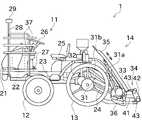
次に、図面を参照して本発明の実施の形態を説明する。図1は、本発明の一実施形態に係る基準局表示システム100に関する田植機1の側面図である。図2は、田植機1の平面図である。図3は、田植機1及び無線通信端末7のブロック図である。また、図3には、基準局表示システム100と自律走行システム200が示されている。 Next, embodiments of the present invention will be described with reference to the drawings. FIG. 1 is a side view of a
自律走行システム200は、本実施形態では、圃場において作業を行う作業車両として田植機1を使用し、オペレータが無線通信端末7等を用いて指示を行うことで、この田植機1に自律走行させつつ、田植機1に作業(苗の植付作業)を行わせるものである。なお、本発明における作業車両は、田植機1に限定されるものではなく、例えば、播種機、トラクタ、コンバイン等を使用することができる。 In the present embodiment, the
自律走行とは、田植機1が備える制御部により走行に関する装置が制御されることで、予め定められた経路に沿うように少なくとも操舵が自律的に行われることを意味する。また、操舵に加え、車速又は作業機による作業等が自律的に行われる構成であってもよい。自律走行には、田植機1に人が乗っている場合と、田植機1に人が乗っていない場合が含まれる。 Autonomous travel means that at least steering is autonomously performed along a predetermined route by controlling a device related to travel by a control unit provided in the
図1及び図2に示すように、田植機1は、車体部11と、前輪12と、後輪13と、植付部14と、を備えている。前輪12及び後輪13は、それぞれ、車体部11に対して左右1対で設けられている。 As shown in FIGS. 1 and 2 , the
車体部11は、ボンネット21を備えている。ボンネット21は、車体部11の前部に設けられている。ボンネット21の内部には、エンジン22が設けられている。 The
エンジン22が発生させた動力は、ミッションケース23を介して前輪12及び後輪13に伝達される。この動力は、ミッションケース23と、車体部11の後部に配置されたPTO軸24と、を介して、植付部14にも伝達される。 Power generated by the
車体部11は、運転座席25と、複数の操作部材と、を更に備えている。運転座席25には、オペレータが座ることができる。運転座席25は、車体部11の前後方向において前輪12と後輪13の間に配置されている。複数の操作部材は、操舵ハンドル26と、変速操作ペダル27と、を有している。 The
操舵ハンドル26を操作することにより、田植機1を操舵することができる。変速操作ペダル27を操作することにより、田植機1の走行速度(車速)を調節することができる。 The
植付部14は、車体部11の後方に配置されている。植付部14は、昇降リンク機構31を介して車体部11に連結されている。昇降リンク機構31は、トップリンク31a及びロワーリンク31bを含む平行リンクにより構成されている。 The
昇降リンク機構31において、ロワーリンク31bには、昇降装置の昇降シリンダ32が連結されている。前記昇降装置は、昇降シリンダ32を伸縮させることによって、植付部14を車体部11に対して上下に昇降させることができる。なお、昇降シリンダ32は、本実施形態においては油圧シリンダとしているが、電動シリンダとしてもよい。また、前記昇降装置は、シリンダ以外のアクチュエータにより植付部14を昇降させるものであってもよい。 In the
植付部14は、植付入力ケース部33と、複数の植付ユニット34と、苗載台35と、複数のフロート36と、予備苗台37と、を備えている。植付部14は、各植付ユニット34に対して苗を苗載台35から順次供給し、苗の植付けを連続的に行うことができる。 The
各植付ユニット34は、植付伝動ケース部41と、回転ケース部42と、を有している。植付伝動ケース部41には、PTO軸24及び植付入力ケース部33を介して動力が伝達される。 Each
回転ケース部42は、植付伝動ケース部41に回転可能に取り付けられている。回転ケース部42は、植付伝動ケース部41の車幅方向の両側に配置されている。各回転ケース部42の一側には、2つの植付爪43が取り付けられている。 The
2つの植付爪43は、田植機1の進行方向に並べられている。2つの植付爪43は、回転ケース部42の回転に伴い変位する。2つの植付爪43が変位することにより、1条分の苗の植付が行われる。 The two
苗載台35は、複数の植付ユニット34の前上方に配置されている。苗載台35は、苗マットを載置可能である。苗載台35は、当該苗載台35に載置された苗マットの苗を各植付ユニット34に対して供給できるように構成されている。 The
具体的には、苗載台35は、車幅方向に往復するように横送り移動可能に(横方向にスライド可能に)構成されている。また、苗載台35は、当該苗載台35の往復移動端で苗マットを間欠的に下方に縦送り搬送可能に構成されている。 Specifically, the seedling mounting table 35 is configured to be laterally movable (slideable in the lateral direction) so as to reciprocate in the vehicle width direction. Further, the seedling mounting table 35 is configured so that the seedling mat can be intermittently vertically fed downward at the reciprocating end of the seedling mounting table 35 .
フロート36は、植付部14の下部に揺動可能に設けられている。フロート36は、植付部14の植付姿勢を圃場表面に対して安定させるために、当該フロート36の下面を圃場表面に接触させることができる。 The
予備苗台37は、車体部11に対して左右1対で設けられている。予備苗台37は、ボンネット21の車幅方向外側に配置されている。予備苗台37は、予備のマット苗を収容した苗箱を搭載可能である。 A pair of spare seedling stands 37 are provided on the left and right sides of the
左右1対の予備苗台37の上部同士は、上下方向及び車幅方向に延びる連結フレーム28によって連結されている。連結フレーム28の車幅方向の中央に、筐体29が設けられている。筐体29の内部には、測位アンテナ61と、慣性計測装置62と、通信アンテナ63と、が設けられている。 The upper parts of the pair of left and right spare seedling stands 37 are connected to each other by a connecting
測位アンテナ61は、衛星測位システム(GNSS)を構成する測位衛星からの電波を受信することができる。この電波に基づいて公知の測位計算が行われることにより、田植機1の位置を取得することができる。 The
慣性計測装置62は、3つのジャイロセンサ(角速度センサ)と、3つの加速度センサと、を有している。慣性計測装置62が検出する田植機1の角速度及び加速度が補助的に用いられることによって、田植機1の測位結果の精度が高められる。 The
通信アンテナ63は、図3に示す無線通信端末7と無線通信を行うためのアンテナである。 The
図3に示すように、制御部50は、図示しない演算装置、記憶装置、及び入出力部等を備える。記憶装置には、各種のプログラム及びデータ等が記憶されている。演算装置は、各種のプログラムを記憶装置から読み出して実行することができる。上記のハードウェアとソフトウェアの協働により、制御部50を、走行制御部51及び作業機制御部52として動作させることができる。制御部50は、1つのハードウェアであってもよいし、互いに通信可能な複数のハードウェアであってもよい。また、制御部50には、上記の慣性計測装置62に加え、位置取得部64と、通信処理部65と、車速センサ66と、舵角センサ67と、が接続されている。 As shown in FIG. 3, the
位置取得部64は、測位衛星から測位アンテナ61が受信した電波に基づいて、田植機1(移動局)の測位情報を取得する。より詳細には、位置取得部64は、電波を受信した測位衛星のそれぞれについて、測位衛星から測位アンテナ61までの擬似距離と、電波が測位アンテナ61に到達したときの搬送波位相と、を取得する。この擬似距離は、測位衛星の内部時計と、位置取得部64の内部時計と、を用いて計測された信号伝搬時間に光速を乗じることにより得られる。また、搬送波位相は、測位アンテナ61で受信された搬送波の位相と、位置取得部64の内部発振器が出力する位相と、の差を測定することにより得られる。 The
加えて、位置取得部64は、位置が既知の基準局120に関して、測位衛星から基準局120までの擬似距離と、基準局120に到達したときの搬送波位相と、に基づいて生成された測位補正情報を取得する。位置取得部64は、図3に示すように、基準局120と田植機1とが直接通信を行うことで、測位補正情報を取得する。なお、位置取得部64は、インターネット及び無線通信端末7等を介して測位補正情報を取得してもよい。 In addition, the
位置取得部64は、田植機1で得られた観測値である測位情報と、基準局120で生成された測位補正情報と、を用いて、公知のGNSS-RTK法による計算を行うことにより、移動局としての田植機1と、基準局120と、の間の基線解を連続的に算出する。これにより、田植機1の位置である測位解がリアルタイムで求められる。GNSS-RTK法では、田植機1と基準局120の双方でGNSS衛星からの電波の搬送波位相を検出して測位計算に用いるので、通常の単独測位よりも著しく高い精度で、田植機1の位置を取得することができる。なお、GNSS-RTK法に代えて、例えばディファレンシャルGNSSを用いた測位演算が行われてもよい。 The
通信処理部65は、通信アンテナ63に電気的に接続されている。この通信処理部65は、適宜の方式で変調処理又は復調処理を行って、無線通信端末7との間でデータの送受信を行うことができる。 The
車速センサ66は、田植機1の車速を検出することができる。車速センサ66は、田植機1の適宜の位置、例えば前輪12の車軸に設けられる。この場合、車速センサ66は、前輪12の車軸の回転に応じたパルスを発生させる。車速センサ66で得られた検出結果のデータは、制御部50へ出力される。 A
舵角センサ67は、前輪12の舵角を検出することができる。舵角センサ67は、田植機1の適宜の位置、例えば前輪12に設けられた図示しないキングピンに設けられる。なお、舵角センサ67は、操舵ハンドル26に設けられてもよい。舵角センサ67で得られた検出結果のデータは、制御部50へ出力される。 A
走行制御部51は、田植機1の走行に関する自動制御を行うことができる。例えば、走行制御部51は、車速制御及び操舵制御を行うことができる。走行制御部51は、車速制御及び操舵制御の両方を同時に行ってもよいし、操舵制御のみを行うようにしてもよい。後者の場合、田植機1の車速は、オペレータが変速操作ペダル27を用いて操作する。 The
車速制御では、予め定められた条件に基づいて田植機1の車速が調整される。車速制御は、具体的には、走行制御部51が、車速センサ66の検出結果により得られた現在の車速を目標の車速に近づける制御を行う。この制御は、ミッションケース23内の変速装置の変速比、及び、エンジン22の回転速度のうち、少なくとも一方を変更することにより実現される。なお、この車速制御は、田植機1が停止するように車速をゼロにする制御も含む。 In vehicle speed control, the vehicle speed of the
操舵制御とは、予め定められた条件に基づいて田植機1の舵角を調整する制御である。操舵制御は、具体的には、走行制御部51が、舵角センサ67の検出結果により得られた現在の舵角を目標の舵角に近づける制御を行う。この制御は、例えば、操舵ハンドル26の回転軸に設けられた操舵アクチュエータを駆動することにより実現される。なお、操舵制御に関しては、走行制御部51が、操舵ハンドル26の回動角度ではなく、田植機1の前輪12の操舵角を直接調整してもよい。 Steering control is control for adjusting the steering angle of the
作業機制御部52は、予め定められた条件に基づいて植付部14の動作(昇降動作又は植付作業等)を制御可能である。 The work
無線通信端末7は、タブレット端末であり、通信アンテナ71と、通信処理部72と、表示部73と、操作部74と、制御部80と、を備える。なお、無線通信端末7はタブレット端末に限るものではなく、スマートフォン又はノートパソコンであってもよい。無線通信端末7は、後述のように田植機1の自律走行に関する様々な処理を行うが、これらの処理の少なくとも一部を田植機1の制御部50が行うこともできる。逆に、田植機1の制御部50が行う自律走行に関する様々な処理の少なくとも一部を無線通信端末7が行うこともできる。 The
通信アンテナ71は、田植機1と無線通信を行うための近距離通信用のアンテナと、携帯電話回線及びインターネットを利用した通信を行うための携帯通信用アンテナと、を含んで構成されている。通信処理部72は、通信アンテナ71に電気的に接続されている。通信処理部72は、適宜の方式で変調処理又は復調処理を行って、無線通信端末7又は他の機器との間でデータの送受信を行うことができる。従って、例えば制御部50又は制御部80に記憶される情報の一部を外部のサーバに記憶させることもできる。 The
表示部73は、液晶ディスプレイ又は有機ELディスプレイ等であり、画像を表示可能に構成されている。表示部73は、例えば、自律走行に関する情報、田植機1の設定に関する情報、各種センサの検出結果、及び警告情報等を表示することができる。操作部74は、タッチパネルと、ハードウェアキーと、を含んでいる。タッチパネルは、表示部73に重ねて配置されており、オペレータの指等による操作を検出可能である。ハードウェアキーは、無線通信端末7の筐体の側面又は表示部73の周囲等に配置されており、オペレータが押圧することで操作可能である。なお、無線通信端末7は、タッチパネルとハードウェアキーの何れか一方のみを備える構成であってもよい。 The
制御部80は、図示しない演算装置、記憶装置、及び入出力部等を備える。記憶装置には、各種のプログラム及びデータ等が記憶されている。演算装置は、各種のプログラムを記憶装置から読み出して実行することができる。上記のハードウェアとソフトウェアの協働により、制御部80を、記憶部81、固定局情報取得部82、表示制御部83、基準局選択部84、基準局設定部85、領域登録部86、及び判定部87として動作させることができる。制御部80の各部が行う処理は後述する。 The
次に、図4及び図5を参照して、圃場を登録する際に基準局の情報を表示する処理について説明する。図4は、圃場を登録するために用いる基準局を決定する処理を示すフローチャートである。図5は、圃場を登録するために用いる基準局を選択する画面が表示されている状態を示す図である。 Next, with reference to FIGS. 4 and 5, the process of displaying the information of the reference station when registering a field will be described. FIG. 4 is a flow chart showing the process of determining a reference station to be used for field registration. FIG. 5 is a diagram showing a state in which a screen for selecting a reference station to be used for field registration is displayed.
田植機1に自律走行を行わせるための事前設定として、自律走行を行う対象となる圃場(走行領域)を登録する必要がある。本実施形態では、田植機1を圃場の外周に沿って走行させた際の位置情報の推移に基づいて、圃場の位置及び形状を示すデータが作成されて無線通信端末7又は上述のサーバに登録される。上述したように、本実施形態では、単独測位ではなく基準局からの測位補正情報に基づいて、田植機1の位置を取得するため、圃場の登録に用いる基準局を決定する必要がある。 As a pre-setting for allowing the
また、基準局には、固定基準局と、可搬基準局と、が存在する。固定基準局は、設置位置が定められた基準局である。固定基準局は、例えば公共機関によって設置されており、設置位置及び通信範囲等の仕様が公開されている。可搬基準局は、地面等に対して固定することは可能であるが、一部又は全部を取り外して設置位置を変更することが可能に構成されている。なお、単に「基準局」と称した場合は、原則として、固定基準局と可搬基準局を含むものとする。 Also, the reference stations include fixed reference stations and portable reference stations. A fixed reference station is a reference station whose installation position is determined. Fixed reference stations are installed, for example, by public institutions, and specifications such as installation locations and communication ranges are made public. The portable reference station can be fixed to the ground or the like, but is configured to be able to change the installation position by removing part or all of it. In principle, the term "reference station" includes fixed reference stations and portable reference stations.
初めに、制御部80(固定局情報取得部82)は、固定基準局の位置及び通信範囲を取得する(S101)。固定局情報取得部82は、固定基準局の情報が公開されている場合は、該当するデータベースにアクセスして、固定基準局の情報を取得する。なお、記憶部81又は上述のサーバ等に固定基準局の情報が記憶されている場合は、それにアクセスして固定基準局の情報を取得してもよい。また、上記のデータベースにアクセスした取得した情報を用いて、記憶部81等に記憶されている固定基準局の情報を更新してもよい。 First, the control unit 80 (fixed station information acquisition unit 82) acquires the position and communication range of the fixed reference station (S101). If the information on the fixed reference station is open to the public, the fixed station
次に、制御部80は、位置取得部64が算出した田植機1の現在位置を取得する(S102)。ここで取得する田植機1の現在位置は、通信可能な固定基準局を特定するためであるため、高い位置精度は要求されない。従って、位置取得部64は、例えば単独測位により田植機1の位置を取得する。あるいは、無線通信端末7に測位アンテナが設けられている場合は、この測位アンテナが受信した電波を用いて単独測位を行って、現在位置を取得してもよい。 Next, the
次に、制御部80は、ステップS101で取得した固定基準局の位置及び通信範囲と、ステップS102で取得した現在位置と、に基づいて、現在位置が通信範囲に含まれる固定基準局を特定する(S103)。 Next, based on the position and communication range of the fixed reference station acquired in step S101 and the current position acquired in step S102, the
次に、制御部80(表示制御部83)は、固定基準局の位置及び通信範囲を地図上に表示する(S104)。具体的には、表示制御部83は、図5に示す画像を表示部73に表示する制御を行う。表示部73には、現在位置アイコン101と、基準局アイコン103と、通信範囲円104と、が表示されている。現在位置アイコン101は、ステップS102で取得した現在位置を示す。基準局アイコン103は、ステップS101で取得した固定基準局の位置を示す。通信範囲円104は、ステップS101で取得した固定基準局の通信範囲を示す。本実施形態では、これらの位置及び領域を、文字ではなく地図上の位置でグラフィカルに示すため、オペレータが状況を直感的に把握し易い。 Next, the control unit 80 (display control unit 83) displays the position and communication range of the fixed reference station on the map (S104). Specifically, the
また、現在位置と重なっている通信範囲円104(言い換えれば、現在位置で通信可能な基準局の通信範囲円104)は、他の通信範囲円104とは異なる態様で表示される。異なる態様とは、例えば、通信範囲内の色が異なる、輪郭の色が異なる、点滅の有無が異なる等である。また、可搬基準局の位置及び通信範囲等が予め登録されている場合は、可搬基準局についても位置及び通信範囲を表示してもよい。この場合、可搬基準局と固定基準局を表示する態様を異ならせてもよい。 Also, the
また、図5に長方形等で示されているように、この地図には、圃場の情報が含まれている。圃場の情報は、例えば航空写真等に基づいて作成された情報である。なお、現時点では圃場の登録が行われていないので、圃場の厳密な位置及び形状は登録されていない。地図に圃場の情報を表示することで、登録対象の圃場が、どの固定基準局の通信範囲に含まれているかを直感的に把握できる。なお、地図には、圃場以外の情報が含まれていてもよい。 In addition, as indicated by rectangles and the like in FIG. 5, this map includes information on agricultural fields. The field information is information created based on, for example, aerial photographs. At this time, the fields have not been registered, so the precise position and shape of the fields have not been registered. By displaying field information on the map, it is possible to intuitively grasp which fixed reference station's communication range includes the field to be registered. Note that the map may include information other than fields.
次に、制御部80(基準局選択部84)は、圃場の登録に用いる基準局を自ら選択するか、オペレータの選択を受け付ける(S105)。登録対象の圃場の全体において田植機1が自律走行を行う可能性があるため、登録対象の圃場の全体が同じ基準局の通信範囲に含まれている必要がある。例えば、図6に示す例では、現在位置は、基準局アイコン103a,103bで示す2つの基準局の通信範囲内である。また、通信範囲円104aには圃場の全体が含まれているが、通信範囲円104bには圃場の一部しか含まれていない。従って、このような状況では、基準局アイコン103aで示す基準局を選択する必要がある。具体的な処理としては、基準局選択部84は、登録対象の圃場の位置情報(地図に含まれる圃場情報)と、基準局の位置及び通信範囲と、を比較することで、登録対象の圃場の全体が通信範囲内となる基準局(選択基準局)を選択する。なお、図5の表示に基づいて、オペレータが基準局(選択基準局)を選択し、基準局選択部84がその選択を受け付けてもよい。 Next, the control unit 80 (reference station selection unit 84) either selects the reference station to be used for field registration by itself or accepts the operator's selection (S105). Since there is a possibility that the
また、ステップS104において表示制御部83が表示した表示物(現在位置アイコン101、基準局アイコン103、及び通信範囲円104)の少なくとも1つは、表示の有無が切替可能である。 At least one of the objects (the
その後、圃場の登録が行われる。具体的には、オペレータは、圃場の登録を行うよう無線通信端末7に指示した後に、田植機1を操縦して圃場の外周に沿って走行させる。その間において、位置取得部64は、ステップS105で選択された基準局から受信した測位補正情報及び測位アンテナ61が受信した測位情報を用いて田植機1の現在位置及びその変化を算出する。制御部80(領域登録部86)は、位置取得部64から取得した現在位置の変化に基づいて圃場の位置及び形状を示すデータを作成して、無線通信端末7又は上述のサーバに登録する。また、圃場の登録に用いられた基準局についても、圃場と関連付けて登録される。このとき、固定基準局と可搬基準局の何れを用いて圃場を登録したかについても併せて登録してもよい。圃場登録時の基準局が第2基準局に相当する。圃場の登録後、圃場内に、田植機1を自律走行させるための走行経路が作成される。 Field registration is then performed. Specifically, after instructing the
次に、自律走行の開始時に基準局に関する情報を表示する処理について、図7から図9を参照して説明する。図7は、自律走行に用いる基準局の設定に関する処理を示すフローチャートである。図8及び図9は、自律走行に用いる基準局の確認及び変更のための画面が表示されている状態を示す図である。以下の説明では、田植機1は、オペレータの指示又は他の条件に基づいて選択された基準局に接続されているものとする。 Next, processing for displaying information about the reference station at the start of autonomous travel will be described with reference to FIGS. 7 to 9. FIG. FIG. 7 is a flow chart showing processing related to setting a reference station used for autonomous driving. 8 and 9 are diagrams showing states in which screens for confirming and changing reference stations used for autonomous driving are displayed. In the following description, it is assumed that the
初めに、制御部80(固定局情報取得部82)は、固定基準局の位置を取得する(S201)。固定基準局の位置の取得方法は、ステップS101と同じである。また、制御部80は、可搬基準局を用いて圃場を登録した場合は、その可搬基準局の位置を取得する(S202)。次に、制御部80は、現在接続中の基準局を特定する(S203)。なお、現在接続中の基準局から取得した測位補正情報を用いて田植機1の位置を取得して自律走行を行わせるため、現在接続中の基準局が第1基準局に相当する。基準局から受信する測位補正情報には、基準局を特定するための情報(識別情報又は設置位置)が含まれているため、この情報に基づいて、現在接続中の基準局を特定できる。 First, the control unit 80 (fixed station information acquisition unit 82) acquires the position of the fixed reference station (S201). The method of acquiring the position of the fixed reference station is the same as in step S101. Further, when the agricultural field is registered using the portable reference station, the
次に、制御部80(表示制御部83)は、地図上における基準局の位置を地図とともに表示部73に表示する(S204)。この地図にも、圃場の情報が含まれている。ここで表示される圃場の位置及び形状は、上記で登録した情報に基づくものである。また、自律走行の対象の圃場は、他とは異なる態様で表示されている(図8及び図9では、自律走行の対象の圃場にドットが付加されている)。また、表示制御部83は、図8に示すように、現在接続中であることを特定する表示、及び、圃場登録時に用いたことを特定する表示を付加して基準局の位置を表示する。具体的には、表示制御部83は、現在接続中の基準局については、基準局アイコン106を太字で表示する。また、表示制御部83は、圃場登録時の基準局については、基準局アイコン106に丸印を付加する。なお、現在接続中の基準局が圃場登録時の基準局と一致している場合は、図9に示すように、太字かつ丸印が付加された基準局アイコン106が表示される。このように、現在接続中の基準局を特定する表示と、圃場登録時の基準局を特定する表示と、は重複して適用可能であることが好ましい。本実施形態では、基準局の位置を、文字ではなく地図上の位置としてグラフィカルに示すため、オペレータが状況を直感的に把握し易い。 Next, the control unit 80 (display control unit 83) displays the position of the reference station on the map together with the map on the display unit 73 (S204). This map also contains field information. The position and shape of the field displayed here are based on the information registered above. In addition, the field targeted for autonomous driving is displayed in a manner different from the others (dots are added to the field targeted for autonomous driving in FIGS. 8 and 9). In addition, as shown in FIG. 8, the
ここで、可搬基準局を用いる場合は、例えば圃場Aで田植機1の自律走行を行う際は圃場Aの近傍に可搬基準局が配置され、その後に圃場Bで田植機1の自律走行を行う際は圃場Bの近傍に可搬基準局を移動させて設置することがある。ここで、圃場Bの近傍に可搬型基準局を移動させることをオペレータが忘れた場合、現在接続中の基準局と圃場登録時の基準局とが一致しないため、可搬基準局を移動させる必要がある。しかし、可搬基準局の設置候補が複数ある場合、オペレータは、何れの可搬基準局を、何れの設置先に移動させればよいか適切に判断できない場合がある。特に、従来のように現在接続中の基準局の位置と、圃場登録時の基準局の位置と、が文字のみで記載されている場合、オペレータが判断に迷う可能性がある。この点、本実施形態のように、両者を地図上の位置として図8のように表示することで、オペレータは、何れの可搬基準局を何れの設置先に移動させればよいかを直感的に判断できる。 Here, when the portable reference station is used, for example, when the
なお、本実施形態の表示制御部83は、画面内に存在する基準局を全て表示部73に表示する構成であるが、現在接続中の基準局及び圃場登録時の基準局のみを表示部73に表示する構成であってもよい。更には、最も重要なのは圃場登録時の基準局であるため、表示制御部83は、圃場登録時の基準局のみを表示部73に表示する構成であってもよい。 Note that the
また、基準局アイコン106を選択することで、詳細ウインドウ107が表示される。詳細ウインドウ107には、この基準局の識別情報及び位置(緯度経度)等が表示される。また、選択した基準局アイコン106が圃場登録時の基準局である場合、圃場登録日時が更に表示される。なお、詳細ウインドウ107に表示される情報は、常時表示される構成であってもよい。 Further, by selecting the
次に、制御部80(判定部87)は、現在接続中の基準局と圃場登録時の基準局とが一致するか否かを判定する(S205)。この判定は、圃場の登録時に登録した基準局に関する情報と、現在接続中の基準局から受信した情報と、を比較することで行われる。判定部87は、例えば、両者の基準局の識別情報を比較してもよいし、両者の基準局の設置位置を比較してもよい。 Next, the control unit 80 (determining unit 87) determines whether or not the currently connected reference station matches the reference station at the time of field registration (S205). This determination is made by comparing the information about the reference station registered when the field was registered with the information received from the currently connected reference station. For example, the
現在接続中の基準局と圃場登録時の基準局とが一致しないと判定部87が判定した場合、制御部80(表示制御部83)は、その旨を示す警告メッセージをメッセージウインドウ108に表示する(S206、図8)。更に、表示制御部83は、圃場登録時の基準局の詳細ウインドウ107に、接続切替ボタン107aを表示する(S206)。なお、この警告メッセージをメッセージウインドウ108以外の箇所に表示してもよいし、接続切替ボタン107aを詳細ウインドウ107以外に表示してもよい。 If the determining
ここで、接続先の基準局を固定基準局へ変更することは容易であるのに対し、例えば接続先の基準局を可搬基準局へ変更するには別の処理(例えば可搬基準局を移動させる処理、可変基準局を起動させる処理、又はその他設定等)が必要となることがある。従って、表示制御部83は、田植機1及び無線通信端末7の処理のみで基準局の変更が可能か否かを判定し、それが可能である場合にのみ接続切替ボタン107aを表示する構成であってもよい。更に、表示制御部83は、圃場登録時の基準局の位置に、使用可能な基準局が配置されていることを、接続切替ボタン107aを表示させる条件に加えてもよい。 Here, while it is easy to change the connection destination reference station to a fixed reference station, for example, to change the connection destination reference station to a portable reference station, another process (for example, a process to move the portable reference station, a variable processing to activate the reference station, or other settings, etc.) may be required. Therefore, the
次に、制御部80(基準局設定部85)は、接続切替ボタン107aがオペレータに操作されたか否かを判定し(S207)、接続切替ボタン107aが操作されたと判定した場合、接続先の基準局を圃場登録時の基準局に変更する(S208)。この処理に伴い、現在接続中の基準局が圃場登録時の基準局と一致するため、制御部80(表示制御部83)は、その旨のメッセージをメッセージウインドウ108に表示する(S209、図9)。なお、ステップS205において、現在接続中の基準局と圃場登録時の基準局が一致していると判定された場合も、ステップS209の処理が行われる。 Next, the control unit 80 (reference station setting unit 85) determines whether or not the
以上に説明したように、本実施形態の基準局表示システム100は、位置取得部64と、領域登録部86と、表示制御部83と、を備える。位置取得部64は、走行領域に作成された走行経路に沿って田植機1を自律走行させるための田植機1の位置を、第1基準局から取得した測位補正情報に基づいて取得する。領域登録部86は、走行領域の形状を特定するために用いる位置を、第2基準局から取得した測位補正情報に基づいて取得して走行経路を登録する。表示制御部83は、田植機1の自律走行に関する設定を行う際に、地図及び当該地図上における第2基準局の位置を表示部73に表示する制御を行う。 As described above, the reference
これにより、第2基準局の位置を地図上に表示することができるので、第1基準局と第2基準局の位置が異なっていた場合でも、オペレータは、第1基準局を設定すべき位置を直感的に把握することができる。 As a result, the position of the second reference station can be displayed on the map, so even if the positions of the first reference station and the second reference station are different, the operator can intuitively determine the position where the first reference station should be set. can grasp.
また、本実施形態の基準局表示システム100は、第1基準局と第2基準局の位置が一致しているか否かを判定する判定部87を備える。表示制御部83は、第1基準局の位置と第2基準局の位置が一致していないと判定部87が判定した場合、更に、第1基準局の位置と第2基準局の位置が一致していないことを示す警告メッセージを表示部73に表示する制御を行う。 The reference
これにより、オペレータは、第1基準局の位置と第2基準局の位置が異なっているか否かを簡単に把握することができる。 Thereby, the operator can easily grasp whether the position of the first reference station and the position of the second reference station are different.
また、本実施形態の基準局表示システム100の表示制御部83は、田植機1を自律走行させるための設定を行う際に、更に、地図及び当該地図上における第1基準局の位置を表示部73に表示する制御を行う。 Further, the
これにより、オペレータは、第1基準局の位置と第2基準局の位置が異なっているか否かを簡単に把握することができる。また、第1基準局が可搬型である場合、オペレータは、第1基準局を何処に移動すべきかを簡単に把握することができる。 Thereby, the operator can easily grasp whether the position of the first reference station and the position of the second reference station are different. Also, if the first reference station is portable, the operator can easily grasp where to move the first reference station.
また、本実施形態の基準局表示システム100は、第1基準局の位置と第2基準局の位置が一致しておらず、第2基準局の位置に基準局が存在しており、かつ、切替操作が行われたことを検出した場合に、第1基準局の位置が第2基準局の位置に一致するように基準局を切り替える処理を行う基準局設定部85を備えることが好ましい。 Further, in the reference
これにより、簡単な処理で第1基準局の位置を第2基準局の位置に一致させることができる。 This makes it possible to match the position of the first reference station with the position of the second reference station by simple processing.
また、本実施形態の基準局表示システム100は、固定局情報取得部82と、表示制御部83と、基準局選択部84と、位置取得部64と、領域登録部86と、を備える。固定局情報取得部82は、位置が固定された基準局である固定基準局の位置情報及び通信範囲を取得する。表示制御部83は、地図上における、固定基準局の位置及び固定基準局の通信範囲を、圃場が含まれた地図とともに表示部73に表示する制御を行う。基準局選択部84は、走行領域の登録対象の圃場が通信範囲内となる固定基準局を選択基準局として選択する又は当該選択基準局の選択を受け付ける。位置取得部64は、走行領域に作成された走行経路に沿って田植機1を自律走行させるための田植機1の位置を、選択基準局から取得した測位補正情報に基づいて取得する。領域登録部86は、走行領域の形状を特定するために用いる位置を、選択基準局から取得した測位補正情報に基づいて取得して走行経路を登録する。 The reference
これにより、固定基準局の位置、通信範囲、及び圃場が地図上に表示されるので、オペレータは、走行領域として登録する圃場の全体で通信可能な固定基準局(即ち、選択基準局)を直感的に選択できる。また、基準局選択部が選択を行う場合であっても、オペレータは、適切な固定基準局が選択されているかを直感的に確認できる。 As a result, the position of the fixed reference station, the communication range, and the field are displayed on the map, so the operator intuitively selects the fixed reference station (that is, the selected reference station) that can communicate with the entire field registered as the travel area. can. Moreover, even when the reference station selection unit performs the selection, the operator can intuitively check whether an appropriate fixed reference station is selected.
以上に本発明の好適な実施の形態を説明したが、上記の構成は例えば以下のように変更することができる。 Although the preferred embodiments of the present invention have been described above, the above configuration can be modified, for example, as follows.
上記実施形態では、基準局の位置等を無線通信端末7の表示部73に表示する構成であるが、別の装置(例えば田植機1に設けられた表示部又はオペレータが所持する別の端末等)に表示する構成であってもよい。 In the above embodiment, the position and the like of the reference station are displayed on the
上記実施形態では、自律走行で用いる基準局を確認する画面(図8及び図9)において、基準局の通信範囲を表示していないが、図5等に示すように通信範囲を表示してもよい。 In the above embodiment, the communication range of the reference station is not displayed on the screen (FIGS. 8 and 9) for confirming the reference station used in autonomous driving, but the communication range may be displayed as shown in FIG. 5 or the like.
上記実施形態では、自律走行の設定時において、オペレータの指示又は他の条件に基づいて選択された基準局に田植機1が接続されている。これに対し、圃場登録時の基準局が存在する場合は、自律走行の設定時において、この基準局に田植機1が自動的に接続される構成であってもよい。 In the above embodiment, the
1 田植機(作業車両)
7 無線通信端末
64 位置取得部
82 固定局情報取得部
83 表示制御部
84 基準局選択部
85 基準局設定部
86 領域登録部
87 判定部
100 基準局表示システム1 rice transplanter (work vehicle)
7
Claims (4)
Translated fromJapanese走行領域に作成された走行経路に沿って作業車両を自律走行させるための当該作業車両の位置を、第1基準局から取得した測位補正情報に基づいて取得する位置取得部と、
前記走行領域の形状を特定するために用いる位置を、第2基準局から取得した測位補正情報に基づいて取得して前記走行経路を登録する領域登録部と、
を備え、
前記表示制御部は、前記作業車両の自律走行に関する設定を行う際に、前記走行領域の登録時に用いた前記第2基準局と、前記作業車両に現在接続されている前記第1基準局と、を含む前記基準局の位置を地図上に表示することを特徴とする基準局表示システム。displayed on the displaya display control unit that displays the position of the reference station on the map;
a position acquisition unit that acquires the position of the work vehicle for autonomously traveling along the travel route created in the travel area based on the positioning correction information acquired from the first reference station;
an area registration unit that acquires a position used to identify the shape of the travel area based on positioning correction information acquired from a second reference station and registers the travel route;
with
The display control unit includes the second reference station used when registering the travel area and the first reference station currently connected to the work vehicle when performing settings related to autonomous travel of the work vehicle. A reference station display system, wherein the position of the reference station is displayed on a map.
前記第1基準局と前記第2基準局の位置が一致しているか否かを判定する判定部を備え、
前記表示制御部は、前記第1基準局の位置と前記第2基準局の位置が一致していないと前記判定部が判定した場合、更に、前記第1基準局の位置と前記第2基準局の位置が一致していないことを示す警告を前記表示部に表示する制御を行うことを特徴とする基準局表示システム。A reference station display system according to claim 1, comprising:
A determination unit that determines whether the positions of the first reference station and the second reference station match,
When the determination unit determines that the position of the first reference station and the position of the second reference station do not match, the display control unit further controls the position of the first reference station and the position of the second reference station to match each other. A reference station display system, wherein control is performed to display a warning indicating non-matching on the display unit.
前記第1基準局の位置と前記第2基準局の位置が一致していない場合であって、かつ、前記第2基準局の位置に前記基準局が存在している場合において、前記作業車両の接続先を前記第2基準局に切り替える切替処理を行う基準局設定部を備え、
前記表示制御部は、前記切替処理が行われたことを検出した場合に、前記第1基準局の位置と前記第2基準局の位置とを一致させて表示することを特徴とする基準局表示システム。 Claim 1or 2The reference station display system according to
The position of the first reference station and the position of the second reference station matchandThe reference station is present at the location of the second reference stationa reference station setting unit that performs switching processing for switching a connection destination of the work vehicle to the second reference station,
The display control unit determines that the switching process has been performed.is detected, the position of the first reference stationWhenPosition of the second reference stationWhenMatch theto displayA reference station display system characterized by:
地図上における、前記固定基準局の位置及び前記固定基準局の通信範囲を、圃場が含まれた地図とともに表示部に表示する制御を行う表示制御部と、
走行領域の登録対象の圃場が通信範囲内となる前記固定基準局を選択基準局として選択する又は当該選択基準局の選択を受け付ける基準局選択部と、
前記走行領域に作成された走行経路に沿って作業車両を自律走行させるための当該作業車両の位置を、前記選択基準局から取得した測位補正情報に基づいて取得する位置取得部と、
前記走行領域の形状を特定するために用いる位置を、前記選択基準局から取得した測位補正情報に基づいて取得して前記走行経路を登録する領域登録部と、
を備えることを特徴とする基準局表示システム。a fixed station information acquisition unit that acquires position information and a communication range of a fixed reference station, which is a reference station whose position is fixed;
a display control unit that performs control to display the position of the fixed reference station and the communication range of the fixed reference station on the map together with the map including the farm field on the display unit;
a reference station selection unit that selects as a selection reference station the fixed reference station within a communication range of a field whose travel area is to be registered, or receives selection of the selection reference station;
a position acquisition unit that acquires the position of the work vehicle for autonomously traveling along the travel route created in the travel area based on the positioning correction information acquired from the selection reference station;
an area registration unit that acquires a position used to identify the shape of the travel area based on the positioning correction information acquired from the selection reference station and registers the travel route;
A reference station display system comprising:
Priority Applications (2)
| Application Number | Priority Date | Filing Date | Title |
|---|---|---|---|
| JP2019006580AJP7117060B2 (en) | 2019-01-18 | 2019-01-18 | Reference station display system |
| JP2022120280AJP7373618B2 (en) | 2019-01-18 | 2022-07-28 | Reference station display system and reference station display method |
Applications Claiming Priority (1)
| Application Number | Priority Date | Filing Date | Title |
|---|---|---|---|
| JP2019006580AJP7117060B2 (en) | 2019-01-18 | 2019-01-18 | Reference station display system |
Related Child Applications (1)
| Application Number | Title | Priority Date | Filing Date |
|---|---|---|---|
| JP2022120280ADivisionJP7373618B2 (en) | 2019-01-18 | 2022-07-28 | Reference station display system and reference station display method |
Publications (2)
| Publication Number | Publication Date |
|---|---|
| JP2020115108A JP2020115108A (en) | 2020-07-30 |
| JP7117060B2true JP7117060B2 (en) | 2022-08-12 |
Family
ID=71778963
Family Applications (2)
| Application Number | Title | Priority Date | Filing Date |
|---|---|---|---|
| JP2019006580AActiveJP7117060B2 (en) | 2019-01-18 | 2019-01-18 | Reference station display system |
| JP2022120280AActiveJP7373618B2 (en) | 2019-01-18 | 2022-07-28 | Reference station display system and reference station display method |
Family Applications After (1)
| Application Number | Title | Priority Date | Filing Date |
|---|---|---|---|
| JP2022120280AActiveJP7373618B2 (en) | 2019-01-18 | 2022-07-28 | Reference station display system and reference station display method |
Country Status (1)
| Country | Link |
|---|---|
| JP (2) | JP7117060B2 (en) |
Families Citing this family (3)
| Publication number | Priority date | Publication date | Assignee | Title |
|---|---|---|---|---|
| JP7018087B2 (en)* | 2020-03-30 | 2022-02-09 | ソフトバンク株式会社 | Correction server, mobile terminal, correction method, and program |
| KR102415916B1 (en)* | 2020-11-04 | 2022-07-05 | 주식회사 긴트 | System and method for monitoring the driving of agricultural vehicle |
| JP7265079B1 (en) | 2022-08-18 | 2023-04-25 | Kddi株式会社 | Information processing device and information processing method |
Citations (6)
| Publication number | Priority date | Publication date | Assignee | Title |
|---|---|---|---|---|
| US20010022558A1 (en) | 1996-09-09 | 2001-09-20 | Tracbeam Llc | Wireless location using signal fingerprinting |
| JP2004289269A (en) | 2003-03-19 | 2004-10-14 | Matsushita Electric Ind Co Ltd | Mobile communication system, information providing device, and mobile communication terminal |
| JP2007248362A (en) | 2006-03-17 | 2007-09-27 | Hitachi Ltd | Terminal positioning system and position measuring method |
| JP2010078525A (en) | 2008-09-26 | 2010-04-08 | Brother Ind Ltd | Positioning system |
| JP2018147164A (en) | 2017-03-03 | 2018-09-20 | ヤンマー株式会社 | Work screen display system |
| JP2018163138A (en) | 2017-03-24 | 2018-10-18 | 東芝テック株式会社 | Positioning device and program |
Family Cites Families (2)
| Publication number | Priority date | Publication date | Assignee | Title |
|---|---|---|---|---|
| JPH10281778A (en)* | 1997-04-08 | 1998-10-23 | Mitsubishi Electric Corp | Mobile receiver system and receiving method of mobile receiver system |
| JP2008032693A (en) | 2006-06-28 | 2008-02-14 | Kankyo Kenkyu Center:Kk | Destination position guidance method and system |
- 2019
- 2019-01-18JPJP2019006580Apatent/JP7117060B2/enactiveActive
- 2022
- 2022-07-28JPJP2022120280Apatent/JP7373618B2/enactiveActive
Patent Citations (6)
| Publication number | Priority date | Publication date | Assignee | Title |
|---|---|---|---|---|
| US20010022558A1 (en) | 1996-09-09 | 2001-09-20 | Tracbeam Llc | Wireless location using signal fingerprinting |
| JP2004289269A (en) | 2003-03-19 | 2004-10-14 | Matsushita Electric Ind Co Ltd | Mobile communication system, information providing device, and mobile communication terminal |
| JP2007248362A (en) | 2006-03-17 | 2007-09-27 | Hitachi Ltd | Terminal positioning system and position measuring method |
| JP2010078525A (en) | 2008-09-26 | 2010-04-08 | Brother Ind Ltd | Positioning system |
| JP2018147164A (en) | 2017-03-03 | 2018-09-20 | ヤンマー株式会社 | Work screen display system |
| JP2018163138A (en) | 2017-03-24 | 2018-10-18 | 東芝テック株式会社 | Positioning device and program |
Also Published As
| Publication number | Publication date |
|---|---|
| JP2022161916A (en) | 2022-10-21 |
| JP7373618B2 (en) | 2023-11-02 |
| JP2020115108A (en) | 2020-07-30 |
Similar Documents
| Publication | Publication Date | Title |
|---|---|---|
| JP7526142B2 (en) | Route management system | |
| JP7373618B2 (en) | Reference station display system and reference station display method | |
| JP7227070B2 (en) | Autonomous driving system | |
| JP7137270B2 (en) | Autonomous driving system | |
| JP2019170197A (en) | Region registration system | |
| JP6850759B2 (en) | Autonomous steering device | |
| JP7714714B2 (en) | Autonomous driving system and method | |
| JP2021085800A (en) | Work machine | |
| JP7098769B2 (en) | Autonomous driving system | |
| WO2020240982A1 (en) | Autonomous travel system | |
| KR102728946B1 (en) | Domain registration system | |
| JP2021083343A (en) | Region registration system |
Legal Events
| Date | Code | Title | Description |
|---|---|---|---|
| A621 | Written request for application examination | Free format text:JAPANESE INTERMEDIATE CODE: A621 Effective date:20210112 | |
| A131 | Notification of reasons for refusal | Free format text:JAPANESE INTERMEDIATE CODE: A131 Effective date:20210908 | |
| A521 | Request for written amendment filed | Free format text:JAPANESE INTERMEDIATE CODE: A523 Effective date:20211105 | |
| A131 | Notification of reasons for refusal | Free format text:JAPANESE INTERMEDIATE CODE: A131 Effective date:20220208 | |
| A521 | Request for written amendment filed | Free format text:JAPANESE INTERMEDIATE CODE: A523 Effective date:20220401 | |
| TRDD | Decision of grant or rejection written | ||
| A01 | Written decision to grant a patent or to grant a registration (utility model) | Free format text:JAPANESE INTERMEDIATE CODE: A01 Effective date:20220628 | |
| RD03 | Notification of appointment of power of attorney | Free format text:JAPANESE INTERMEDIATE CODE: A7423 Effective date:20220728 | |
| A61 | First payment of annual fees (during grant procedure) | Free format text:JAPANESE INTERMEDIATE CODE: A61 Effective date:20220728 | |
| R150 | Certificate of patent or registration of utility model | Ref document number:7117060 Country of ref document:JP Free format text:JAPANESE INTERMEDIATE CODE: R150 |