JP7116854B2 - Heater assembly and flavor sucker - Google Patents
Heater assembly and flavor suckerDownload PDFInfo
- Publication number
- JP7116854B2 JP7116854B2JP2022069198AJP2022069198AJP7116854B2JP 7116854 B2JP7116854 B2JP 7116854B2JP 2022069198 AJP2022069198 AJP 2022069198AJP 2022069198 AJP2022069198 AJP 2022069198AJP 7116854 B2JP7116854 B2JP 7116854B2
- Authority
- JP
- Japan
- Prior art keywords
- channel
- aerosol
- container assembly
- container
- atomization chamber
- Prior art date
- Legal status (The legal status is an assumption and is not a legal conclusion. Google has not performed a legal analysis and makes no representation as to the accuracy of the status listed.)
- Active
Links
Images


Description
Translated fromJapanese本発明は、ヒータアッセンブリ及び香味吸引器に関する。 The present invention relates to heater assemblies and flavor inhalers.
従来、燃焼を伴わずに香味発生物品を加熱する香味吸引器が知られている。香味吸引器は、エアロゾル源を霧化するヒータと、ヒータがエアロゾル源を加熱することによって生じるエアロゾルのチャネルの少なくとも一部を有する霧化チャンバと、霧化チャンバにインレットから空気を供給する吸気チャネルと、を備える(例えば、特許文献1-3)。 Conventionally, flavor inhalers are known that heat flavor-generating articles without combustion. The flavor inhaler includes a heater for atomizing an aerosol source, an atomization chamber having at least a portion of a channel for the aerosol produced by the heater heating the aerosol source, and an intake channel for supplying air from an inlet to the atomization chamber. and (for example,
第1の特徴は、ヒータアッセンブリであって、エアロゾル源を霧化するヒータと、前記ヒータが前記エアロゾル源を加熱することによって生じるエアロゾルが通るエアロゾルチャネルの少なくとも一部として所定方向に沿って延びる霧化チャンバと、前記霧化チャンバにインレットから空気を供給する吸気チャネルと、を備え、前記吸気チャネルは、前記所定方向に沿って延在するとともに、前記インレットに連通する第1チャネルと、前記所定方向に沿った前記ヒータアッセンブリの断面視において、前記所定方向と交差する交差方向に沿って前記第1チャネルから延びる第2チャネルと、前記第2チャネルから前記所定方向に沿って延在する第3チャネルと、を含む、ことを要旨とする。 A first feature is a heater assembly, a heater for atomizing an aerosol source and a mist extending along a predetermined direction as at least part of an aerosol channel through which the aerosol produced by said heater heats said aerosol source. and an intake channel for supplying air from an inlet to the atomization chamber, the intake channel extending along the predetermined direction and communicating with the inlet; In a cross-sectional view of the heater assembly along a direction, a second channel extending from the first channel along a direction crossing the predetermined direction, and a third channel extending from the second channel along the predetermined direction. The gist is to include: a channel;
第2の特徴は、第1の特徴において、前記第3チャネルは、前記交差方向において前記霧化チャンバに隣接する、ことを要旨とする。 The second feature is of the first feature, wherein the third channel is adjacent to the atomization chamber in the cross direction.
第3の特徴は、第1の特徴又は第2の特徴において、前記第2チャネルは、前記エアロゾルチャネルの内周又は外周に沿って延びる形状を有する、ことを要旨とする。 A third feature is the gist of the first or second feature, wherein the second channel has a shape extending along an inner circumference or an outer circumference of the aerosol channel.
第4の特徴は、第3の特徴において、前記第2チャネルは、前記エアロゾルチャネルの内周又は外周に沿って第1方向に延びるチャネルと、前記エアロゾルチャネルの内周又は外周に沿って前記第1方向とは反対の第2方向に延びるチャネルと、を含む、ことを要旨とする。 A fourth feature is the third feature, wherein the second channel includes a channel extending in a first direction along the inner circumference or outer circumference of the aerosol channel and a channel extending in the first direction along the inner circumference or outer circumference of the aerosol channel. and a channel extending in a second direction opposite the one direction.
第5の特徴は、第3の特徴において、前記第2チャネルは、前記エアロゾルチャネルの内周又は外周に沿って螺旋状に延びる形状を有する、ことを要旨とする。 A fifth feature is the gist of the third feature, wherein the second channel has a shape extending spirally along an inner circumference or an outer circumference of the aerosol channel.
第6の特徴は、第1の特徴乃至第5の特徴のいずれか1つにおいて、前記ヒータアッセンブリは、前記吸気チャネルから前記霧化チャンバに空気が流入する側に設けられた第1端と、前記霧化チャンバからエアロゾルが流出する側に設けられた第2端と、を備え、前記第3チャネルは、前記第1端と前記第2端との間の範囲において前記霧化チャンバと隣接する位置に設けられる、ことを要旨とする。 A sixth feature is that in any one of the first to fifth features, the heater assembly has a first end provided on a side where air flows into the atomization chamber from the intake channel; a second end provided on the side from which the aerosol exits the atomization chamber, the third channel adjoining the atomization chamber in an area between the first end and the second end. provided at a position.
第7の特徴は、第1の特徴乃至第6の特徴のいずれか1つにおいて、前記エアロゾル源は、柱状形状を有する柱状物品であり、前記霧化チャンバは、前記柱状物品を収容するとともに、前記吸気チャネルから前記霧化チャンバに空気が流入する側に設けられた第1端で前記柱状物品を支持する、ことを要旨とする。 A seventh feature is any one of the first to sixth features, wherein the aerosol source is a columnar article having a columnar shape, and the atomization chamber accommodates the columnar article, The gist of the invention is that the columnar article is supported at a first end provided on a side where air flows into the atomization chamber from the intake channel.
第8の特徴は、第1の特徴乃至第7の特徴のいずれか1つにおいて、前記インレットから空気が吸引される場合に、前記霧化チャンバは、前記第3チャネル内の空気の流れの向きの反対方向に、前記エアロゾル源から生じるエアロゾルを導く、ことを要旨とする。 An eighth feature is that in any one of the first to seventh features, when air is sucked from the inlet, the atomization chamber is adapted to the direction of air flow in the third channel. directing the aerosol originating from said aerosol source in the opposite direction of said aerosol source.
第9の特徴は、第7の特徴又は第7の特徴を引用する第8の特徴において、前記第2チャネルの少なくとも一部は、前記柱状物品が前記霧化チャンバに挿入された状態において前記柱状物品の外側側面によって構成される、ことを要旨とする。 A ninth feature is the seventh feature or the eighth feature citing the seventh feature, wherein at least part of the second channel is formed in the columnar shape when the columnar article is inserted into the atomization chamber. The gist is that it is constituted by an outer side surface of an article.
第10の特徴は、第7の特徴又は第7の特徴を引用する第8の特徴において、前記ヒータアッセンブリは、前記第2チャネルに隣接する位置において前記柱状部材の外側側面に沿って設けられる筒状部材を備え、前記第2チャネルの少なくとも一部は、前記筒状部材の外側側面によって構成される、ことを要旨とする。 A tenth feature is the seventh feature or the eighth feature citing the seventh feature, wherein the heater assembly is a cylinder provided along the outer side surface of the columnar member at a position adjacent to the second channel. A tubular member, wherein at least a portion of said second channel is defined by an outer side surface of said tubular member.
第11の特徴は、第1の特徴乃至第10の特徴のいずれか1つにおいて、前記インレットは、前記交差方向において、前記エアロゾルが導き出されるアウトレットと並んで設けられる、ことを要旨とする。 The gist of the eleventh feature is that in any one of the first to tenth features, the inlet is provided side by side with the outlet from which the aerosol is led out in the cross direction.
第12の特徴は、第11の特徴において、前記ヒータアッセンブリは、前記エアロゾルチャネルの少なくとも一部を構成する空洞を有するカラー部材を備える、ことを要旨とする。 A twelfth aspect is the gist of the eleventh aspect, wherein the heater assembly comprises a collar member having a cavity forming at least a portion of the aerosol channel.
第13の特徴は、第12の特徴において、前記第2チャネルの少なくとも一部は、前記カラー部材によって構成される、ことを要旨とする。 A thirteenth aspect is of the twelfth aspect, wherein at least a portion of the second channel is defined by the collar member.
第14の特徴は、第12の特徴又は第13の特徴において、前記カラー部材が有する前記空洞は、前記エアロゾルチャネルの少なくとも一部及び前記第1チャネルを含む、ことを要旨とする。 A fourteenth aspect is characterized in that in the twelfth aspect or the thirteenth aspect, the cavity of the collar member includes at least a portion of the aerosol channel and the first channel.
第15の特徴は、第1の特徴乃至第14の特徴のいずれか1つにおいて、前記ヒータアッセンブリは、前記霧化チャンバ及び前記第3チャネルを含む空洞を有する容器を備える、ことを要旨とする。 A fifteenth aspect is characterized in that in any one of the first through fourteenth aspects, the heater assembly comprises a container having a cavity containing the atomization chamber and the third channel. .
第16の特徴は、第1の特徴乃至第15の特徴のいずれか1つのヒータアッセンブリを有する香味吸引器を要旨とする。 A sixteenth aspect provides a flavor inhaler having a heater assembly of any one of the first through fifteenth aspects.
以下において、実施形態について説明する。なお、以下の図面の記載において、同一又は類似の部分には、同一又は類似の符号を付している。但し、図面は模式的なものであり、各寸法の比率などは現実のものとは異なる場合があることに留意すべきである。 Embodiments will be described below. In addition, in the following description of the drawings, the same or similar reference numerals are given to the same or similar parts. However, it should be noted that the drawings are schematic, and the ratio of each dimension may differ from the actual one.
従って、具体的な寸法などは以下の説明を参酌して判断すべきものである。また、図面相互間においても互いの寸法の関係や比率が異なる部分が含まれる場合があることは勿論である。 Therefore, specific dimensions should be determined with reference to the following description. In addition, it is needless to say that the drawings may include portions having different dimensional relationships and ratios.
[開示の概要]
上述した背景技術の香味吸引器では、吸気チャネル及びヒータの配置について様々な工夫がなされている。しかしながら、ヒータがエアロゾル源を加熱することによって生じるエアロゾルがインレットから漏れる態様について考慮されておらず、インレットからエアロゾルが漏れる態様について改善が望まれている。[Summary of Disclosure]
In the flavor inhaler of the background art described above, various ideas have been made with respect to the arrangement of the intake channel and the heater. However, no consideration has been given to the manner in which the aerosol generated by heating the aerosol source by the heater leaks from the inlet, and improvements are desired regarding the manner in which the aerosol leaks from the inlet.
開示の概要に係るヒータアッセンブリは、エアロゾル源を霧化するヒータと、前記ヒータが前記エアロゾル源を加熱することによって生じるエアロゾルが通るエアロゾルチャネルの少なくとも一部として所定方向に沿って延びる霧化チャンバと、前記霧化チャンバにインレットから空気を供給する吸気チャネルと、を備える。前記吸気チャネルは、前記所定方向に沿って延在するとともに、前記インレットに連通する第1チャネルと、前記所定方向に沿った前記ヒータアッセンブリの断面視において、前記第1チャネルから前記交差方向に沿って延びる第2チャネルと、前記第2チャネルから前記所定方向に沿って延在する第3チャネルと、を含む。 A heater assembly according to an overview of the disclosure includes a heater for atomizing an aerosol source, and an atomization chamber extending along a predetermined direction as at least part of an aerosol channel through which the aerosol produced by the heater heats the aerosol source. , an intake channel for supplying air from an inlet to the atomization chamber. The intake channel extends along the predetermined direction and communicates with the inlet, and in a cross-sectional view of the heater assembly along the predetermined direction, the intake channel extends from the first channel along the intersecting direction. and a third channel extending from the second channel along the predetermined direction.
開示の概要によれば、吸気チャネルは、第1チャネル、第2チャネル及び第3チャネルを含むクランク形状を有する。このような構成によれば、霧化チャンバからインレットに向けてエアロゾルの逆流が生じるケースを想定した場合であっても、第3チャネルから第2チャネルへの屈曲及び第2チャネルから第1チャネルへの屈曲が吸気チャネルの抵抗を増大するため、吸気チャネルを逆流するエアロゾルの温度を圧力損失によって低下することができる。 According to the summary of the disclosure, the intake channel has a crank shape including a first channel, a second channel and a third channel. According to such a configuration, even if a backflow of the aerosol from the atomization chamber toward the inlet is assumed, the bending from the third channel to the second channel and from the second channel to the first channel are possible. Since bending increases the resistance of the intake channel, the temperature of the aerosol flowing back through the intake channel can be reduced by pressure drop.
[実施形態]
(香味吸引器)
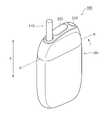
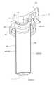
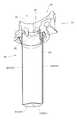
以下において、実施形態に係る香味吸引器について説明する。図1及び図2は、実施形態に係る香味吸引器100を示す図である。図1は、柱状部材110が挿入されていない状態を示す図であり、図2は、柱状部材110が挿入された状態を示す図である。[Embodiment]
(flavor aspirator)
A flavor inhaler according to an embodiment will be described below. 1 and 2 are diagrams showing a
図1及び図2に示すように、香味吸引器100は、エアロゾル源を構成する柱状部材110と、柱状部材110からエアロゾルを生成させる生成装置120と、を有する。香味吸引器100は、燃焼を伴わずにエアロゾルを生成する。香味吸引器100は、加熱タイプ又は非燃焼タイプの香味吸引器と称してもよい。香味吸引器100は、携帯タイプの吸引器であってもよい。 As shown in FIGS. 1 and 2, the
柱状部材110は、個体のエアロゾル源を少なくとも構成する部材であり、所定方向Xに沿って延びる柱状形状を有する。例えば、柱状部材110は、刻みたばこ、たばこ原料を粒状に成形した成形体、たばこ原料をシート状に成形した成形体などによって構成されてもよい。柱状部材110は、個体のエアロゾル源に巻き回されるラッピング材を含んでもよい。柱状部材110は、フィルタを有していてもよい。 The
柱状部材110は、加熱に伴ってエアロゾルを発生してもよく、エアロゾルの発生を促進するためにグリセリン、プロピレングリコール、又は1,3-ブタンジオールなどの各種ポリオールを含むエアロゾル源を含んでもよい。柱状部材110は、たばこ以外の植物(例えば、ミント、ハーブ等)によって構成されてもよい。柱状部材110は、メントールなどの香料を含んでもよい。
生成装置120は、生成装置120の電源をONにする操作部210と、後述するヒータアッセンブリ30に設けられる開口30Xを塞ぐ蓋体220とを有する。操作部210は、生成装置120の電源をOFFにする機能を有していてもよい。蓋体220は、摺動可能に構成されており、柱状部材110を挿入する際に開口30Xを露出させる。蓋体220は、回転可能に構成されていてもよい。生成装置120の詳細については後述する(図3を参照)。 The
(生成装置)
以下において、実施形態に係る生成装置について説明する。図3は、実施形態に係る生成装置120の断面図である。図3では、図1に示すA-A断面が示されている。(generator)
The generation device according to the embodiment will be described below. FIG. 3 is a cross-sectional view of the
図3に示すように、生成装置120は、バッテリ10と、制御回路20と、ヒータアッセンブリ30と、を有する。 As shown in FIG. 3 ,
バッテリ10は、生成装置120で用いる電力を蓄積する。例えば、バッテリ10は、リチウムイオン電池である。バッテリ10は、外部電源によって充電可能であってもよい。
制御回路20は、CPU及びメモリなどによって構成されており、生成装置120の動作を制御する。制御回路20は、操作部210によって生成装置120の電源がONにされた場合に、柱状部材110の加熱を開始する。制御回路20は、加熱開始から一定時間が経過した場合に、柱状部材110の加熱を停止してもよい。制御回路20は、加熱開始から一定回数のパフ動作が行われた場合に、柱状部材110の加熱を停止してもよい。制御回路20は、操作部210によって生成装置120の電源がOFFにされた場合に、柱状部材110の加熱を停止してもよい。パフ動作は、センサ(不図示)によって検出されてもよい。センサは、後述する底板部分41(例えば、離間部分41B)に設けられてもよい。 The
ヒータアッセンブリ30は、柱状部材110を加熱することによってエアロゾルを発生する。ヒータアッセンブリ30は、開口30Xを有しており、柱状部材110は、開口30Xからヒータアッセンブリ30内に挿入される。ヒータアッセンブリ30は、カラー部材31と、容器40と、ヒータ50と、を有する。ヒータアッセンブリ30は、断熱部材60を有してもよい。但し、断熱部材60は、ヒータアッセンブリ30の一部ではなくてもよい。カラー部材31及び容器40の詳細については後述するため、ここでは、ヒータ50及び断熱部材60について主として説明する。 The
ヒータ50は、容器40の外側側面に配置される。特に、ヒータ50は、容器40の外側側面(周面)の少なくとも一部を覆うように配置される。ヒータ50は、エアロゾル源を霧化する。具体的には、ヒータ50は、容器40に収容される柱状部材110を加熱する。図3では、ヒータ50が容器40の外側側面に配置されるケースを例示する。ヒータ50は、ポリイミドなどのフィルムによって構成される基材及び金属などの抵抗発熱体によって構成される加熱要素によって構成されてもよい。加熱要素は、2つの基材の間に挟まれていてもよい。加熱要素を構成する金属は、ニッケル合金、クロム合金、ステンレス及び白金ロジウムの中から選択された1以上の金属であってもよい。 A
断熱部材60は、ヒータ50の外側において容器40を覆うように配置される。断熱部材60は、二重構造を有する真空断熱部材であってもよい。断熱部材60は、エアロゲル、シリコンなどの断熱材料によって構成されてもよい。 The
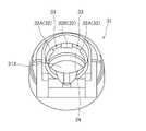
(ヒータアッセンブリ)
以下において、実施形態に係るヒータアッセンブリについて説明する。図4及び図5は、実施形態に係るヒータアッセンブリ30を示す断面図である。図4は、図1に示すA-A断面におけるヒータアッセンブリ30を示しており、柱状部材110が挿入された状態を示す図である。図5は、図2に示すA-A断面におけるヒータアッセンブリ30を示しており、柱状部材110が挿入されていない状態を示す図である。図4及び図5では、上述したヒータ50及び断熱部材60が省略されている。(heater assembly)
A heater assembly according to an embodiment will be described below. 4 and 5 are cross-sectional views showing the
図4及び図5に示すように、ヒータアッセンブリ30は、カラー部材31と、容器40と、を有する。 As shown in FIGS. 4 and 5,
カラー部材31は、筒状形状を有しており、例えば、可塑性を有する合成樹脂によって構成される。カラー部材31は、柱状部材110を受け入れるための開口30Xを有する。開口30Xは、柱状部材110がヒータアッセンブリ30に挿入された状態で、ヒータアッセンブリ30内に空気を導き入れるインレット120INと、ヒータアッセンブリ30からエアロゾルを導き出すアウトレット120OUTと、を含む。 The
実施形態では、エアロゾルが柱状部材110内を通るため、アウトレット120OUTは、柱状部材110によって占有される部分である。インレット120INは、柱状部材110によって占有されない部分である。開口30Xは、柱状部材110を挿入しやすいように、インレット120IN及びアウトレット120OUTよりも大きい。カラー部材31は、柱状部材110の挿入ガイドとして機能してもよい。 In the embodiment, the outlet 120OUT is the portion occupied by the
実施形態では、インレット120INは、所定方向Xと交差する交差方向Yにおいてアウトレット120OUTと並んで設けられる。特に限定されるものではないが、交差方向Yは、所定方向Xに対する直交方向と比べて-45°~45°の角度を有する方向と考えてもよい。 In the embodiment, the inlet 120IN is provided side by side with the outlet 120OUT in a cross direction Y crossing the predetermined direction X. Although not particularly limited, the cross direction Y may be considered as a direction having an angle of -45° to 45° with respect to the direction orthogonal to the predetermined direction X.
容器40は、所定方向Xに沿って延びる形状を有する。容器40は、カラー部材31を介して挿入される柱状部材110を収容する部材である。容器40は、熱伝導性部材(例えば、SUS(Steel Use Stainless)などの金属)によって構成される。容器40は、柱状部材110が挿入された状態で、柱状部材110によって占有される部分(以下、霧化チャンバ)を有する。 The
容器40は、吸気チャネル(図5では、第1チャネル81~第4チャネル84)から霧化チャンバ(図5では、第5チャネル85)に空気が流入する側に設けられた第1端40Aと、霧化チャンバから空気が流出する側に設けた第2端40Bと、を有する。 The
容器40は、底板部分41及び筒状部分42を有する。底板部分41は、第1端40Aを塞ぐ。すなわち、容器40は、底板部分41及び筒状部分42によって構成されるカップ形状を有する。容器40は、金属板の絞り加工などの手法によって一体成形されてもよい。 The
底板部分41は、第1端40Aにおいて、台座部分41A及び離間部分41Bを有する。具体的には、台座部分41Aは、柱状部材110が挿入された状態で、柱状部材110の底面と接触しており、柱状部材110を支持する。離間部分41Bは、柱状部材110の底面から離間する方向に出っ張る形状を有しており、柱状部材110の底面から離間する。柱状部材110によって占有される部分が霧化チャンバであるため、台座部分41Aは、霧化チャンバの一部を構成すると考えてよい。離間部分41Bは、吸気チャネル(図5では、第4チャネル84)の一部を構成すると考えてよい。 The
このような前提下において、ヒータアッセンブリ30は、第1チャネル81と、第2チャネル82と、第3チャネル83と、第4チャネル84と、第5チャネル85と、第6チャネル86と、を有する。 Under this premise, the
第1チャネル81は、所定方向Xに沿って延在するとともに、インレット120INに連通するチャネルである。第2チャネルは、所定方向Xに沿ったヒータアッセンブリ30の断面視において、所定方向Xと交差する交差方向Yに沿って第1チャネル81から延びるチャネルである。第3チャネル83は、第2チャネル82から所定方向Xに沿って延在するチャネルである。第4チャネル84は、第3チャネル83から第5チャネル85に連通するチャネルである。第5チャネル85及び第6チャネル86は、所定方向Xに沿って延在するとともに、アウトレット120OUTに連通するチャネルである。 The
実施形態では、第1チャネル81~第4チャネルは、霧化チャンバ(図5では、第5チャネル85)にインレット120INから空気を供給する吸気チャネルを構成する。第5チャネル85及び第6チャネル86は、ヒータ50によってエアロゾル源(ここでは、柱状部材110)を加熱することによって生じるエアロゾルのチャネル(以下、エアロゾルチャネル)を構成する。第5チャネル85は、エアロゾルチャネルの少なくとも一部を構成する霧化チャンバを構成する。 In the embodiment, the
上述したように、実施形態では、柱状部材110をエアロゾルが流れるため、エアロゾルチャネルが柱状部材110そのものであると考えてもよい。霧化チャンバは、エアロゾルチャネルのうち、ヒータ50による加熱が寄与する部分である。従って、霧化チャンバは、容器40が有する空洞において柱状部材110によって占有される部分である。 As described above, in the embodiment, since the aerosol flows through the
第3チャネル83は、交差方向Yにおいて霧化チャンバ(図5では、第5チャネル)に隣接する。第3チャネル83は、所定方向Xにおいて第1端40Aと第2端40Bとの間の範囲において霧化チャンバに隣接する位置に設けられる。言い換えると、第3チャネル83は、所定方向Xにおける容器40の全範囲に亘って設けられてもよい。上述したように、霧化チャンバが柱状部材110であると考えてもよいため、第3チャネル83は、容器40が有する空洞において柱状部材110によって占有されない部分である。 The
続いて、インレット120INからアウトレット120OUTに至る気体の流れについて説明する。第1に、インレット120INから第1チャネル81に流入する空気は、所定方向Xに沿った空気流F1として第1チャネル81を通過する。第2に、第1チャネル81から第2チャネル82に流入する空気は、交差方向Yに沿った空気流F2として第2チャネル82を通過する。第3に、第2チャネル82から第3チャネル83に流入する空気は、所定方向Xに沿った空気流F3として第3チャネル83を通過する。第4に、第3チャネル83から第5チャネル85に導かれる空気は、空気流F4として第4チャネル84を通過する。第5に、第5チャネル85に流入する空気は、柱状部材110から生じるエアロゾルと混合された上で、エアロゾル流F5として第5チャネル85及び第6チャネル86を通過する。 Next, gas flow from the inlet 120IN to the outlet 120OUT will be described. First, air flowing into the
ここで、第5チャネル85及び第6チャネル86におけるエアロゾル流F5の向きは、第3チャネルにおける空気流F3の向きと反対である。すなわち、インレット120INから空気が吸引される場合に、霧化チャンバ(第5チャネル85)は、第3チャネルの空気の流れの向きと反対方向に、柱状部材110から生じるエアロゾルを導く。 Here, the direction of the aerosol flow F5 in the
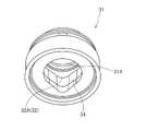
(カラー部材)
以下において、実施形態に係るカラー部材について説明する。図6及び図7は、実施形態に係るカラー部材31を示す図である。(Collar member)
A collar member according to the embodiment will be described below. 6 and 7 are diagrams showing the
図6及び図7に示すように、カラー部材31は、上述した第1チャネル81、第2チャネル82及び第6チャネル86を含む空洞31Xを有する。空洞31Xは、開口30X(すなわち、インレット120IN及びアウトレット120OUT)に連通する。空洞31Xは、第3チャネル83及び第5チャネル85(後述する空洞40X)に連通する。カラー部材31は、突起部分32と、切欠き部分33と、壁体34と、を有する。 As shown in FIGS. 6 and 7,
突起部分32は、壁体34よりも空洞31Xの内側に突出する部分である。突起部分32は、柱状部材110が空洞31Xに挿入された状態で、柱状部材110の外側側面と接触するように設けられる。ここでは、突起部分32として、突起部分32A及び突起部分32Bが設けられるケースについて例示する。突起部分32Aは、空洞31Xの外周に沿って連続する。 The protruding
切欠き部分33は、突起部分32Aと突起部分32Bとの間に設けられる。切欠き部分33は、インレット120INから流入する空気が通る第1チャネル81を構成する。 The
壁体34は、筒状形状を有しており、空洞31Xの少なくとも一部を構成する。壁体34は、突起部分32及び切欠き部分33よりも容器40側に位置する。壁体34は、柱状部材110の外側側面と離間して設けられる。言い換えると、壁体34の内側側面と柱状部材110の外側側面との間に隙間が設けられる。壁体34の内側側面及び柱状部材110の外側側面は、切欠き部分33から流入する空気が通る第2チャネル82を構成する。 The
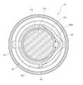
(容器)
以下において、実施形態に係る容器について説明する。図8~図10は、実施形態に係る容器40を示す図である。図10は、図5に示すB-B断面を示す図である。(container)
Below, the container which concerns on embodiment is demonstrated. 8 to 10 are diagrams showing the
図8~図10に示すように、容器40は、上述した第3チャネル83、第4チャネル84及び第5チャネル85を含む空洞40Xを有する。空洞40Xは、カラー部材31の空洞31Xと連通する。容器40は、底板部分41及び筒状部分42を有する。 As shown in FIGS. 8-10, the
底板部分41は、第1端40Aにおいて、台座部分41A及び離間部分41Bを有する。台座部分41Aは、柱状部材110が空洞40Xに挿入された状態で、柱状部材110の底面と接触する。すなわち、台座部分41Aは、柱状部材110を支持する。離間部分41Bは、柱状部材110が空洞40Xに挿入された状態で、柱状部材110の底面から離間する。なお、第1端40Aは図示した構造のみに限定されず、柱状部材110の底面またはその近傍を少なくとも部分的に支持可能であればいかなる構造を有していてもよい。 The
筒状部分42は、空洞40Xを区画しており、保持部分42A及び離間部分42Bを有する。保持部分42Aは、柱状部材110が空洞40Xに挿入された状態で、柱状部材110の外側側面と接触する。上述したように、霧化チャンバは柱状部材110によって占有されるチャンバであるため、保持部分42Aは、霧化チャンバを区画する部材であると考えてもよい。離間部分42Bは、柱状部材110が空洞40Xに挿入された状態で、柱状部材110の外側側面から離間する。すなわち、離間部分42Bの内側側面と柱状部材110の外側側面との間には隙間が設けられる。なお、上述したヒータ50は、筒状部分42の外側側面(周面)のうち、保持部分42Aに相当する箇所に少なくとも設けられることができる。ヒータ50は、所定方向Xにおいて、筒状部分42の全長に少なくとも一部にわたって延在することができる。 The
ここで、筒状部分42の離間部分42Bの内側側面及び柱状部材110の外側側面は、第2チャネル82から流入する空気が通る第3チャネル83を構成する。底板部分41の離間部分41Bは、第3チャネル83から第5チャネル85に導かれる空気が通る第4チャネル84を構成する。柱状部材110の底面の一部及び筒状部分42の離間部分42Bの一部も第4チャネル84を構成していると考えてもよい。底板部分41の台座部分41A及び筒状部分42の保持部分42Aは、第5チャネル85(すなわち、霧化チャンバ)を構成する。 Here, the inner side surface of the spaced
実施形態では、空洞40Xは、第3チャネル83及び第5チャネル85を含む。柱状部材110が空洞40Xに挿入されることによって、第3チャネル83及び第5チャネル85が区画される。上述したように、第3チャネル83は、空洞40Xにおいて柱状部材110によって占有されない部分であり、第5チャネル85は、空洞40Xにおいて柱状部材110によって占有される部分である。 In embodiments,
(第2チャネル)
以下において、実施形態に係る第2チャネルについて説明する。図11は、実施形態に係る第2チャネル82を示す図である。図11は、図5に示すC-C断面を示す図である。(Second channel)
The second channel according to the embodiment will be described below. FIG. 11 is a diagram showing a
図11に示すように、第2チャネル82は、第1チャネル81と第3チャネル83とを連通するチャネルである。上述したように、第2チャネル82は、所定方向Xに沿ったヒータアッセンブリ30の断面視(例えば、図5を参照)においては、所定方向Xと交差する交差方向Yに沿って第1チャネル81から延びるチャネルである。 As shown in FIG. 11, the
ここで、第2チャネル82は、カラー部材31の壁体34の内側側面と柱状部材110の外側側面との間に形成される。容器40の第2端40Bが第2チャネル82の少なくとも一部を構成していると考えてもよい。 Here, the
このようなケースにおいて、第2チャネル82は、エアロゾルチャネル(すなわち、柱状部材110又は第6チャネル86)の外周に沿って延びる形状を有する。詳細には、第2チャネル82は、エアロゾルチャネルの内周に沿って第1方向に延びるチャネル821と、エアロゾルチャネルの内周に沿って第1方向とは反対の第2方向に延びるチャネル822と、を含む。In such cases, the
(エアロゾルの漏れ)
以下において、実施形態に係るエアロゾルの漏れについて説明する。図12は、実施形態に係るエアロゾルの漏れについて説明するための図である。図12は、ヒータアッセンブリ30の断面斜視図である。(Leakage of aerosol)
The aerosol leakage according to the embodiment will be described below. FIG. 12 is a diagram for explaining leakage of aerosol according to the embodiment. 12 is a cross-sectional perspective view of the
ここで、エアロゾルの漏れが生じる場合には、第1チャネル81、第2チャネル82及び第3チャネル83が吸気チャネルとして機能せずに、エアロゾルチャネルとして機能してしまう。例えば、エアロゾルの漏れが生じるケースとして、ユーザが吸引動作を行わずに吹き込み動作を行うケースなどが考えられる。 Here, when aerosol leakage occurs, the
図12に示すように、霧化チャンバから生じるエアロゾルは、所定方向Xに沿ったエアロゾル流R3として第3チャネル83を通過する。続いて、第3チャネル83から第2チャネル82に流入するエアロゾルは、交差方向Yに沿ったエアロゾル流R2として第2チャネル82を通過する。第2チャネル82から第1チャネル81に流入するエアロゾルは、所定方向Xに沿ったエアロゾル流R1として第1チャネル81を通過する。このようにして、エアロゾルがインレット120INから漏れる。 The aerosol emerging from the atomization chamber passes through the
すなわち、吸気チャネルを逆流するエアロゾルは、エアロゾル流R3からエアロゾル流R2への屈曲、エアロゾル流R2からエアロゾル流R1への屈曲を繰り返す。従って、吸気チャネルを逆流するエアロゾルの温度を圧力損失によって低下することができる。 That is, the aerosol flowing back through the intake channel repeats bending from the aerosol flow R3 to the aerosol flow R2 and from the aerosol flow R2 to the aerosol flow R1. Therefore, the temperature of the aerosol flowing back through the intake channel can be lowered by the pressure loss.
さらには、エアロゾル流R3がカラー部材31の突起部分32と衝突することによって乱流を生じることも考えられる。このような乱流によってカラー部材31の壁面との熱交換が促進されるのでエアロゾルの温度低下が期待できる。同様に、エアロゾル流R2がカラー部材31の壁体34と衝突することによって乱流を生じることも考えられる。このような乱流もエアロゾルの温度低下に寄与する可能性がある。 Furthermore, it is conceivable that the aerosol flow R3 collides with the protruding
(作用及び効果)
実施形態では、吸気チャネルは、第1チャネル81、第2チャネル82及び第3チャネル83を含むクランク形状を有する。このような構成によれば、霧化チャンバからインレット120INに向けてエアロゾルの逆流が生じるケースを想定した場合であっても、第3チャネル83から第2チャネル82への屈曲及び第2チャネル82から第1チャネル81への屈曲が吸気チャネルの抵抗を増大するため、吸気チャネルを逆流するエアロゾルの温度を圧力損失によって低下することができる。(Action and effect)
In an embodiment, the intake channel has a crank shape including a
[変更例1]
以下において、実施形態の変更例1について説明する。以下においては、実施形態に対する相違点について主として説明する。変更例1では、ヒータアッセンブリ30は、第2チャネル82に隣接する位置において柱状部材110の外側側面に沿って設けられる筒状部材を有する。[Modification 1]
(筒状部材)
以下において、変更例1に係る筒状部材について説明する。図13乃至図15は、変更例1に係る筒状部材90を説明するための図である。図13は、ヒータアッセンブリ30の断面図である。図14及び図15は、容器40を示す斜視図である。図14及び図15では、容器40に加えて、上述した筒状部材90が表されている。(cylindrical member)
The tubular member according to
図13乃至図15に示すように、ヒータアッセンブリ30は、筒状部材90を有する。筒状部材90は、熱伝導性部材(例えば、SUS(Steel Use Stainless)などの金属)によって構成されてもよい。筒状部材90は、容器40と同じ部材によって構成されてもよい。筒状部材90は、第2チャネル82に隣接する位置に設けられる。筒状部材90は、柱状部材110の外側側面に沿って設けられる。言い換えると、筒状部材90の内側側面は、上述した第5チャネル85を区画する。 As shown in FIGS. 13-15, the
ここで、容器40は、第2端40Bに向けて外側に広がるテーパ部分43を有する。テーパ部分43は、所定方向Xにおいて離間部分42B以外の保持部分42Aと連続するように設けられる。テーパ部分43は、筒状部材90の内側側面が保持部分42Aの内側側面と揃うように筒状部材90を保持する。すなわち、筒状部材90は、テーパ部分43において容器40と接触する。 Here,
一方で、第2チャネル82と第3チャネル83とを連通させる必要があるため、筒状部材90は、離間部分42Bから離間する。筒状部材90と離間部分42Bとの間に隙間が設けられる。 On the other hand, the
変更例1では、筒状部材90は、交差方向Yにおいて容器40と重なる部分を含んでいてもよい。例えば、筒状部材90は、テーパ部分43の一部と重なる部分を含んでもよく、離間部分42Bと重なる部分を含んでもよい。 In
(第2チャネル)
以下において、変更例1に係る第2チャネルについて説明する。図16は、変更例1に係る第2チャネル82を示す図である。図16は、図13に示すD-D断面を示す図である。(Second channel)
The second channel according to
図16に示すように、第2チャネル82は、第1チャネル81と第3チャネル83とを連通するチャネルである。上述したように、第2チャネル82は、所定方向Xに沿ったヒータアッセンブリ30の断面視(例えば、図13を参照)においては、所定方向Xと交差する交差方向Yに沿って第1チャネル81から延びるチャネルである。 As shown in FIG. 16, the
ここで、第2チャネル82の少なくとも一部は、筒状部材90の外側側面によって形成される。例えば、第2チャネル82は、カラー部材31の壁体34の内側側面と筒状部材90の外側側面との間に形成される。第2チャネル82は、容器40の保持部分42Aの内側側面と筒状部材90の外側側面との間に形成されてもよい。 Here, at least part of the
このようなケースにおいて、第2チャネル82は、エアロゾルチャネル(すなわち、筒状部材90)の外周に沿って延びる形状を有する。詳細には、第2チャネル82は、エアロゾルチャネルの内周に沿って第1方向に延びるチャネル821と、エアロゾルチャネルの内周に沿って第1方向とは反対の第2方向に延びるチャネル822と、を含む。In such cases, the
(エアロゾルの漏れ)
以下において、変更例1に係るエアロゾルの漏れについて説明する。図17は、変更例1に係るエアロゾルの漏れについて説明するための図である。図17は、ヒータアッセンブリ30の断面斜視図である。(Leakage of aerosol)
The aerosol leakage according to
基本的には、エアロゾルの漏れに関するメカニズムは、上述した図12と同様である。但し、第2チャネル82を逆流するエアロゾル(エアロゾル流R2)は、筒状部材90の外側を通ることに留意すべきである。 Basically, the mechanism for aerosol leakage is the same as in FIG. 12 described above. However, it should be noted that the aerosol flowing back through the second channel 82 (aerosol flow R2) passes through the outside of the
(作用及び効果)
変更例1では、第2チャネル82の少なくとも一部が筒状部材90によって構成される。このような構成によれば、第2チャネル82の少なくとも一部が柱状部材110から隔離されるため、吸気チャネルを逆流するエアロゾルの冷却効率が向上する。例えば、筒状部材90が熱伝導性部材によって構成されることによって冷却効率の向上が期待できる。(Action and effect)
In
[その他の実施形態]
本発明は上述した実施形態によって説明したが、この開示の一部をなす論述及び図面は、この発明を限定するものであると理解すべきではない。この開示から当業者には様々な代替実施形態、実施例及び運用技術が明らかとなろう。[Other embodiments]
Although the present invention has been described by the above-described embodiments, the statements and drawings forming part of this disclosure should not be construed as limiting the present invention. Various alternative embodiments, implementations and operational techniques will become apparent to those skilled in the art from this disclosure.
上述した実施形態等では、第2チャネル82は、2方向に延びるチャネル(チャネル821及びチャネル822を含む(図11及び図16を参照))。しかしながら、実施形態等はこれに限定されるものではない。第2チャネル82は、1方向に延びるチャネル(例えば、チャネル821及びチャネル822のいずれか1つ)を有していてもよい。In embodiments such as those described above, thesecond
上述した実施形態等では特に言及していないが、第2チャネル82は、エアロゾルチャネル(柱状部材110又は筒状部材90)の外周に沿って螺旋状に延びる形状を有していてもよい。このような構成によれば、第2チャネル82のチャネル長が長くなるため、吸気チャネルを逆流するエアロゾルの冷却効率が向上する。 Although not specifically mentioned in the above-described embodiments, the
上述した実施形態等では、第2チャネル82は、エアロゾルチャネル(柱状部材110又は筒状部材90)の外周に沿って延びる形状を有する。しかしながら、実施形態はこれに限定されるものではない。第2チャネル82は、エアロゾルチャネルの内周に沿って延びる形状を有してもよい。例えば、上述した第6チャネル86の内側に第2チャネル82が配置されており、第2チャネル82が第6チャネル86と隔壁等によって区画されていてもよい。 In the embodiments described above and the like, the
実施形態等では特に言及していないが、ヒータ50は、容器40の離間部分42Bに設けられずに、容器40の保持部分42Aのみに設けられてもよい。このような構成によれば、柱状部材110の加熱に寄与しない部分(第3チャネル83に隣接する部分)にヒータ50が配置されないため、第3チャネル83を逆流するエアロゾルの冷却効率の低下が抑制される。 Although not specifically mentioned in the embodiments, the
実施形態等では、ヒータ50が容器40の外側側面に配置されるケースについて例示した。しかしながら、実施形態はこれに限定されるものではない。ヒータ50は、容器40の内側側面に配置されてもよい。或いは、ヒータ50は、柱状部材110内に挿入可能な形状を有してもよい。 In the embodiments and the like, the case in which the
実施形態等では、容器40が有する1つの空洞40Xが第3チャネル83及び第5チャネル85を含む。しかしながら、実施形態はこれに限定されるものではない。第3チャネル83及び第5チャネル85は、隔壁等によって区画された別々の空洞として設けられてもよい。同様に、カラー部材31が有する1つの空洞31Xが第1チャネル81、第2チャネル82及び第6チャネル86を含む。しかしながら、実施形態はこれに限定されるものではない。第1チャネル81、第2チャネル82及び第6チャネル86は、隔壁等によって区画された別々の空洞として設けられてもよい。 In embodiments and the like, one
実施形態等では、ヒータアッセンブリ30は、第1チャネル81、第2チャネル82及び第3チャネル83を含むチャネル群として、第2チャネル82が分岐する形態を含むものの、1つのチャネル群を有する。しかしながら、実施形態はこれに限定されるものではない。例えば、ヒータアッセンブリ30は、2以上のチャネル群を有していていもよい。このようなケースにおいて、2以上のチャネル群は、相互に連通しない形態を有していてもよい。或いは、2以上のチャネル群は、少なくとも一部のチャネルを共有してもよい。例えば、ヒータアッセンブリ30は、2以上の第1チャネル81を有するとともに、2以上の第1チャネル81の双方に連通する第2チャネル82を有していてもよい。このようなケースにおいて、ヒータアッセンブリ30は、1つの第3チャネル83を有していてもよく、2以上の第3チャネル83を有していてもよい。 In the embodiment and the like, the
上述した実施形態等では、エアロゾル源が個体であるケースについて例示した。しかしながら、実施形態等はこれに限定されるものではない。エアロゾル源は、液体であってもよい。例えば、ウィックなどの液保持部材が霧化チャンバ内に配置されており、液保持部材によって保持されるエアロゾル源がヒータによって加熱される。このようなケースにおいて、液体のエアロゾル源から生じるエアロゾルの下流側に固体の香味源(例えば、たばこ源)が設けられてもよい。
In the above-described embodiments and the like, the case where the aerosol source is an individual has been exemplified. However, the embodiments and the like are not limited to this. The aerosol source may be liquid. A liquid retaining member, eg, a wick, is positioned within the atomization chamber and a heater heats the aerosol source retained by the liquid retaining member. In such cases, a solid flavor source (eg, tobacco source) may be provided downstream of the aerosol generated from the liquid aerosol source.
Claims (18)
Translated fromJapanese前記容器に接続され、前記容器の所定方向に沿って延在する第1チャネルの少なくとも一部を構成するカラー部材と、
前記所定方向と交差する交差方向に沿って延在する第2チャネルの少なくとも一部と、
前記所定方向に沿って延在する、前記第1チャネルとは異なる第3チャネルの少なくとも一部と、を備え、
柱状物品が前記霧化チャンバに挿入された状態において、前記第2チャネルの少なくとも一部は、前記柱状物品の外側側面によって構成され、前記第2チャネルは、前記第1チャネルおよび前記第3チャネルと連通する、容器アッセンブリ。a container having an atomization chamber;
a collar member connected to the container and defining at least a portion of a first channel extending along a predetermined direction of the container;
at least a portion of a second channel extending along a cross direction that crosses the predetermined direction;
at least a portion of a third channel, different from the first channel, extending along the predetermined direction;
At least a portion of the second channel is defined by the outer side surface of the columnar article in a state in which the columnar article is inserted into the atomization chamber, and the second channel is the first channel and the third channel. A container assembly in communication.
前記霧化チャンバからエアロゾルが流出する側に設けられた第2端と、を備え、
前記第3チャネルは、前記第1端と前記第2端との間の範囲において前記霧化チャンバと隣接する位置に設けられる、請求項2、請求項2を引用する請求項3乃至請求項6のいずれか1項に記載の容器アッセンブリ。a first end provided on the side from which air flows into the atomization chamber from the intake channel;
a second end provided on the side from which the aerosol flows out of the atomization chamber;
Claim 2, claims 3 to 6 citing claim 2, wherein the third channel is provided at a position adjacent to the atomization chamber in the range between the first end and the second end. A container assembly according to any one of the preceding claims.
前記第1チャネルは、前記切欠き部によって構成される、請求項1乃至請求項11のいずれか1項に記載の容器アッセンブリ。The collar member has a protrusion and a notch,
12. A container assembly as claimed in any preceding claim, wherein the first channel is defined by the notch.
前記加熱要素は、2つの基材の間に挟まれている、請求項15に記載の容器アッセンブリ。The heater has a heating element,
16. The container assembly of Claim 15, wherein the heating element is sandwiched between two substrates.
前記底板部に設けられ、パフ動作を検出するセンサを有する、請求項1乃至請求項16のいずれか1項に記載の容器アッセンブリ。The container has a bottom plate portion and a cylindrical portion,
17. A container assembly according to any one of the preceding claims, comprising a sensor provided on the bottom plate portion for detecting puffing action.
Priority Applications (1)
| Application Number | Priority Date | Filing Date | Title |
|---|---|---|---|
| JP2022069198AJP7116854B2 (en) | 2019-07-01 | 2022-04-20 | Heater assembly and flavor sucker |
Applications Claiming Priority (3)
| Application Number | Priority Date | Filing Date | Title |
|---|---|---|---|
| PCT/JP2019/026147WO2021001896A1 (en) | 2019-07-01 | 2019-07-01 | Heater assembly and flavor inhaler |
| JP2021529574AJP7208394B2 (en) | 2019-07-01 | 2019-07-01 | Heater assembly and flavor sucker |
| JP2022069198AJP7116854B2 (en) | 2019-07-01 | 2022-04-20 | Heater assembly and flavor sucker |
Related Parent Applications (1)
| Application Number | Title | Priority Date | Filing Date |
|---|---|---|---|
| JP2021529574ADivisionJP7208394B2 (en) | 2019-07-01 | 2019-07-01 | Heater assembly and flavor sucker |
Publications (2)
| Publication Number | Publication Date |
|---|---|
| JP2022101626A JP2022101626A (en) | 2022-07-06 |
| JP7116854B2true JP7116854B2 (en) | 2022-08-10 |
Family
ID=87852771
Family Applications (1)
| Application Number | Title | Priority Date | Filing Date |
|---|---|---|---|
| JP2022069198AActiveJP7116854B2 (en) | 2019-07-01 | 2022-04-20 | Heater assembly and flavor sucker |
Country Status (1)
| Country | Link |
|---|---|
| JP (1) | JP7116854B2 (en) |
Citations (4)
| Publication number | Priority date | Publication date | Assignee | Title |
|---|---|---|---|---|
| JP2006505281A (en) | 2002-11-08 | 2006-02-16 | フィリップ・モーリス・プロダクツ・ソシエテ・アノニム | Electric heating cigarette smoking system with internal manifold for puff detection |
| JP2015504667A (en) | 2012-01-03 | 2015-02-16 | フィリップ・モーリス・プロダクツ・ソシエテ・アノニム | Aerosol generator and system with improved airflow |
| JP2018511317A (en) | 2015-03-23 | 2018-04-26 | 雲南中煙工業有限責任公司 | Electric cigarette smoking device with electronic cigarette smoking function |
| WO2018122389A1 (en) | 2016-12-30 | 2018-07-05 | Jt International S.A. | Aerosol generating apparatus, aerosol generating system and method of generating an aerosol |
- 2022
- 2022-04-20JPJP2022069198Apatent/JP7116854B2/enactiveActive
Patent Citations (4)
| Publication number | Priority date | Publication date | Assignee | Title |
|---|---|---|---|---|
| JP2006505281A (en) | 2002-11-08 | 2006-02-16 | フィリップ・モーリス・プロダクツ・ソシエテ・アノニム | Electric heating cigarette smoking system with internal manifold for puff detection |
| JP2015504667A (en) | 2012-01-03 | 2015-02-16 | フィリップ・モーリス・プロダクツ・ソシエテ・アノニム | Aerosol generator and system with improved airflow |
| JP2018511317A (en) | 2015-03-23 | 2018-04-26 | 雲南中煙工業有限責任公司 | Electric cigarette smoking device with electronic cigarette smoking function |
| WO2018122389A1 (en) | 2016-12-30 | 2018-07-05 | Jt International S.A. | Aerosol generating apparatus, aerosol generating system and method of generating an aerosol |
Also Published As
| Publication number | Publication date |
|---|---|
| JP2022101626A (en) | 2022-07-06 |
Similar Documents
| Publication | Publication Date | Title |
|---|---|---|
| KR102532401B1 (en) | Heater assembly and vessel | |
| JP7695432B2 (en) | Heater assembly and flavor inhaler | |
| JP7034902B2 (en) | Aerosol generation system with enhanced airflow management | |
| ES2945209T3 (en) | Aerosol generating system and methods for guiding a flow of air into an electrically heated aerosol generating system | |
| EP3104726B1 (en) | Electronic cigarette | |
| KR20190134793A (en) | Atomizer for Vapor Providing Devices | |
| CN111109664A (en) | Electronic atomization device and atomizer thereof | |
| US10869507B2 (en) | Electronic cigarette and atomizer thereof | |
| CN219125369U (en) | Atomization device and electronic cigarette | |
| US20200405982A1 (en) | Aerosolization Conduit For Electronic Drug-Delivery Systems | |
| JP7116854B2 (en) | Heater assembly and flavor sucker | |
| CN217162790U (en) | Atomization assembly and electronic atomizer | |
| CN214156229U (en) | an electronic atomizer | |
| CN221044258U (en) | Electronic atomizing device | |
| KR102546288B1 (en) | Aerosol generating device | |
| CN116602454A (en) | Electronic atomizing device |
Legal Events
| Date | Code | Title | Description |
|---|---|---|---|
| A521 | Request for written amendment filed | Free format text:JAPANESE INTERMEDIATE CODE: A523 Effective date:20220420 | |
| A621 | Written request for application examination | Free format text:JAPANESE INTERMEDIATE CODE: A621 Effective date:20220420 | |
| A871 | Explanation of circumstances concerning accelerated examination | Free format text:JAPANESE INTERMEDIATE CODE: A871 Effective date:20220420 | |
| TRDD | Decision of grant or rejection written | ||
| A01 | Written decision to grant a patent or to grant a registration (utility model) | Free format text:JAPANESE INTERMEDIATE CODE: A01 Effective date:20220706 | |
| A61 | First payment of annual fees (during grant procedure) | Free format text:JAPANESE INTERMEDIATE CODE: A61 Effective date:20220729 | |
| R150 | Certificate of patent or registration of utility model | Ref document number:7116854 Country of ref document:JP Free format text:JAPANESE INTERMEDIATE CODE: R150 | |
| R250 | Receipt of annual fees | Free format text:JAPANESE INTERMEDIATE CODE: R250 |