JP7114059B2 - tray - Google Patents
trayDownload PDFInfo
- Publication number
- JP7114059B2 JP7114059B2JP2018109152AJP2018109152AJP7114059B2JP 7114059 B2JP7114059 B2JP 7114059B2JP 2018109152 AJP2018109152 AJP 2018109152AJP 2018109152 AJP2018109152 AJP 2018109152AJP 7114059 B2JP7114059 B2JP 7114059B2
- Authority
- JP
- Japan
- Prior art keywords
- tray
- bulging
- positioning
- recesses
- chamfered
- Prior art date
- Legal status (The legal status is an assumption and is not a legal conclusion. Google has not performed a legal analysis and makes no representation as to the accuracy of the status listed.)
- Active
Links
Images


Landscapes
- Containers Having Bodies Formed In One Piece (AREA)
Description
Translated fromJapanese本開示は、荷物を収容する複数の収容凹部を備える樹脂製のトレーに関する。 The present disclosure relates to a resin tray having a plurality of storage recesses for storing luggage.
従来、この種のトレーとして、収容凹部に荷物が嵌合して位置決めされるものが知られている(例えば、特許文献1参照)。 Conventionally, as this type of tray, there has been known a tray in which cargo is fitted into and positioned in an accommodation recess (see, for example, Patent Document 1).
しかしながら、従来のトレーでは、収容凹部の底面の外縁部に亀裂が入り、やがて収容凹部の底部が荷物と共に抜け落ちることが起こり得た。これに対し、従来より耐久性が高いトレーの開発が求められている。 However, in the conventional tray, the outer edge of the bottom surface of the storage recess may crack, and eventually the bottom of the storage recess may fall off together with the load. In response to this, there is a demand for the development of trays with higher durability than conventional trays.
上記課題を解決するためになされた請求項1の発明は、荷物を収容する複数の収容凹部を行列状に並べて備える発泡樹脂製のトレーにおいて、前記複数の収容凹部には、荷物の側面に当接又は隣接する位置決内側面と、前記収容凹部のうち前記行列の行方向及び列方向に対して傾斜する傾斜方向の両側部で前記位置決内側面から側方に膨らむ膨出内側面と、各前記収容凹部の底面のうち前記位置決内側面に沿った外縁部に形成されて、前記荷物の下面外縁部との干渉を回避する逃がし溝と、前記底面と前記膨出内側面との角部に形成される面取り面と、が備えられ、前記収容凹部の底面のうち前記位置決内側面に包囲される部分と、前記膨出内側面に包囲される部分とが面一に連続し、その連続する底面によって前記逃がし溝が分断されているトレーである。The invention of claim 1, which has been made to solve the above-mentioned problems, is a tray made offoamed resin having aplurality of storage recessesarranged in a matrix for storing luggage, whereinthe plurality of storage recesses correspond to the sides of the luggage. a positioning inner side surface that is in contact with or adjacent to the housing recess, and a bulging inner side surface that bulges laterally from the positioning inner side surfaceon both sides of the accommodation recess in an inclination direction that is inclined with respect to the row direction and the column direction of the matrix ; An escape groove formed in the outer edge portion of the bottom surface of each of the accommodation recesses along the positioning inner side surface to avoid interference with the outer edge portion of the lower surface of the cargo, and the corner between the bottom surface and the bulging inner side surface. a chamfered surface formed in the portion,wherein the portion of the bottom surface of the accommodation recess surrounded by the positioning inner side surface and the portion surrounded by the bulging inner side surface are flush with each other; The tray is such that theescape groove is divided by its continuous bottom surface .
請求項2の発明は、前記複数の収容凹部の各底部を貫通する複数の長孔を備え、前記複数の収容凹部は、前記長孔に対する前記位置決内側面及び前記膨出内側面の相対位置が同じになっている請求項1に記載のトレーである。The invention according to claim 2is provided with a plurality of elongated holes penetrating through the respective bottoms of the plurality of accommodating recesses, and the plurality of accommodating recesses are configured such that the relative positions of the positioning inner surface and the bulging inner surface with respect to the elongated holes. are the same .
請求項3の発明は、前記複数の長孔は、それらの長手方向と、前記複数の収容凹部が並ぶ行方向又は列方向とが一致した状態で直線に並べられている請求項2に記載のトレーである。The invention of claim 3 is the invention of claim2, wherein the plurality of long holes are arranged in a straight line with their longitudinal direction aligned with the row direction or column direction in which the plurality of accommodation recesses are arranged . is a tray.
本発明のトレーでは、収容凹部の内側面が、荷物の側面に当接又は隣接する位置決内側面と、位置決内側面から側方に膨らんだ膨出内側面とを含んでなる。そして、収容凹部の底面と内側面との角部のうち、荷物の下面外縁部と干渉し得る位置決内側面と底面との角部には、面取り面を備えず、荷物の下面外縁部と干渉し得ない膨出内側面と底面との角部には、面取り面を備える。これにより、荷物の安定した収容と位置決めとを実現しながらも、面取り面の形成による応力集中の緩和と増肉効果により、トレーの耐久性が向上する。しかも、底面のうち位置決内側面に沿った外縁部には、逃がし溝が形成されているので、荷物の下面外縁部との干渉を確実に防ぐことができる。In the tray of thepresent invention , the inner surface of the accommodation recess includes the positioning inner surface that abuts or adjoins the side surface of the package, and the bulging inner surface that bulges laterally from the positioning inner surface. Of the corners between the bottom surface and the inner side surface of the storage recess, the corners between the positioning inner side surface and the bottom surface that may interfere with the outer edge portion of the lower surface of the package are not provided with a chamfered surface. A chamfered surface is provided at the corner between the bulging inner side surface and the bottom surface that cannot interfere with each other. As a result, the durability of the tray is improved due to the effect of alleviating stress concentration and increasing the thickness of the chamfered surface while stably accommodating and positioning the cargo. Moreover, since the relief groove is formed in the outer edge portion of the bottom surface along the positioning inner side surface, it is possible to reliably prevent interference with the outer edge portion of the lower surface of the package.
なお、逃がし溝の溝底面を湾曲面にすれば、位置決内側面と底面との角部をピン角形状にするより応力集中が防がれ、耐久性が向上する。 If the groove bottom surface of the escape groove is curved, stress concentration is prevented and durability is improved, as compared with forming the corner between the positioning inner side surface and the bottom surface in the shape of a pin.
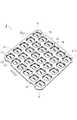
以下、図1~図7に示されたトレー10の実施形態について説明する。本実施形態のトレー10は、例えば、発泡樹脂の成形品であって、図1に示すように全体が略正方形の板状をなしている。トレー10の四隅には、角部を斜めにカットしてコーナー斜面11が形成されている。また、トレー10の対向する1対の側面12,12には、それぞれの両端寄り位置を段付き状に側方から陥没させて凹部13が形成されている。さらに、トレー10の上面のうち一方の側面12側の外縁部の中央には、三角形の目印14が刻印されている。An embodiment of the
トレー10には、上面に開口する複数の収容凹部20が行列状に並べて形成されている。それら収容凹部20は、図5に示すように、トレー10の厚さの1/2~4/5の深さをなしている。収容凹部20の内側面20Sは、トレー10の上面に対して略垂直で、収容凹部20の底面30は、トレー10の上面に対して略平行になっている。 The
また、図4に示すように、収容凹部20の内側面20Sは、円筒状の位置決内側面21と、位置決内側面21から側方に膨らむ複数の膨出内側面22とを含んでなる。そして、図2に示すように、収容凹部20のうち位置決内側面21に包囲された第1エリアR1に円筒状又は円柱状の荷物90が収容され、各膨出内側面22に包囲された第2エリアR2には、荷物90は収容されないようになっている。 As shown in FIG. 4, the
詳細には、図3に示すように、膨出内側面22は、位置決内側面21の周方向において180°離れた2つの位置と、それら2つの位置に挟まれた一方の円弧部の中央とに配置されている。また、各膨出内側面22は、第1エリアR1の中心軸J1と直交する中心線CL2に対して左右対称な略四角形をなし、図4に示すように、膨出内側面22には、中心線CL2(図3参照)と平行な1対の対向面22A,22Aと、中心線CL2と直交する奥面22Bとが含まれている。 Specifically, as shown in FIG. 3, the bulging
以下、膨出内側面22同士を区別する場合は、対向する2位置に配置された膨出内側面22,22を「第1の膨出内側面22,22」といい、それらの中央の膨出内側面22を「第2の膨出内側面22」ということとする。膨出内側面22同士を区別しない場合いは、「第1及び第2の膨出内側面22」又は、単に「膨出内側面22」ということとする。また、本開示において「面取り」とは、一般的な「面取り」の意味と同じで、隣り合う2つの平面が交差する角部に、それら2つの平面に斜めに交差する傾斜平面か、それら2つの平面に連続する円弧面かを形成することをいい、そのような傾斜平面を「C面取り面」といい、「円弧面」を「R面取り面」という。また、これら「C面取り面」と「R面取り面」とを合わせて単に「面取り面」という。 Hereinafter, when distinguishing between the bulging
図4に示すように、第1の膨出内側面22,22は、第2の膨出内側面22に対し、開口幅が3~5倍、奥行きが1.5~3倍の大きさをなしている。また、第1の膨出内側面22の対向面22A,22Aと奥面22Bとの間の角部には、C面取り面22Cが形成されている。一方、第2の膨出内側面22の対向面22A,22Aと奥面22Bとの角部には、R面取り面22Dが形成されている。また、第1及び第2の両膨出内側面22の両側部22A,22Aと位置決内側面21との間の角部には、それぞれR面取り面22Eが備えられている。さらに、収容凹部20の内側面20S全体とトレー10の上面との角部には、R面取り面20Aが形成されている。 As shown in FIG. 4, the first bulging
収容凹部20の底面30は、第1エリアR1と各第2エリアR2とに跨がって面一に連続している。また、第1エリアR1の中心部には、長孔31が貫通している。長孔31は、細長い長方形をなし、その長手方向は、第1の膨出内側面22,22の対向方向に対して45°回転した方向を向いている。また、長孔31の内側面と底面30とが交差する角部には、R面取り面31Aが形成されている。 The
図1に示すように、トレー10の全ての収容凹部20は、長孔31の長手方向が、前述の側面12,12と平行でかつ、第2の膨出内側面22が同じ方向に膨出するように配置されている。これにより、図3に示すように、収容凹部20の配列の行方向及び列方向(図3の縦方向及び横方向)で、隣り合う全てのペアの収容凹部20の対向部分の少なくとも一方に膨出内側面22が含まれるようになっている。 As shown in FIG. 1, in all of the
図4に示すように、底面30のうち位置決内側面21に沿った外縁部には逃がし溝40が形成されている。図7(A)に示すように、逃がし溝40は、位置決内側面21に連続する第1溝側面40Aと、それに内側から対向する第2溝側面40Bと、第1溝側面40Aと第2溝側面40Bとを連絡する湾曲形状の溝底面40Cとを有する。また、第2溝側面40Bと底面30との角部には、R面取り面40Dが形成されている。なお、図4に示すように、逃がし溝40は、底面30のうち位置決内側面21に沿った外縁部からさらにR面取り面22Eの手前位置まで僅かに延長されている。 As shown in FIG. 4 ,
図4に示すように、底面30と膨出内側面22との角部には、面取り面43が形成されている。この面取り面43は、例えば、「R面取り面」であるが、「C面取り面」であってもよい。また、図7(B)に示すように、面取り面43が形成されたことで底面30と膨出内側面22との間に形成される増肉部70のうち位置決内側面21側の側面は、第1エリアR1に向かって傾斜する傾斜面44になっている。より具体的には、傾斜面44としなかった場合の増肉部70の側面は、図7(B)に符号70Aで示したように、膨出内側面22のうち側部22AとR面取り面22Eとの境界22Kに位置し、増肉部70の側面(70A)と底面30との角部が所謂ピン角形状になる。それを回避するために、増肉部70の側面が傾斜面44になっている。 As shown in FIG. 4 , a
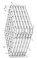
本実施形態のトレー10の構造に関する説明は以上である。次に、本実施形態の作用効果について説明する。このトレー10は、図示しないパレットの上に載置され、例えば、パレットから起立する複数の支柱に凹部13を係合させて位置決めされる。そして、図2に示すように、トレー10の各収容凹部20に荷物90が収容され、それら荷物90の上部がトレー10の上面から突出した状態にされる。 The description about the structure of the
トレー10の全ての収容凹部20に荷物90が収容されたら、その上に別のトレー10が載置され、そのトレー10に荷物90が収容されていく。このようにして、荷物90を収容した複数のトレー10が段積み状態にされる。そして、それらトレー10が、パレットごとフォークリフトにより搬送され、さらにトラックに搭載されて遠方に搬送される。その際、トレー10が緩衝材として機能し、荷物90の損傷が防がれる。 After the
ここで、本実施形態のトレー10では、収容凹部20の内側面20Sが、荷物90の側面に当接又は隣接する位置決内側面21と、位置決内側面21から側方に膨らんだ膨出内側面22とを含んでなる。そして、位置決内側面21に包囲された第1エリアR1に荷物90が収容され、膨出内側面22に包囲された第2エリアR2には、荷物90が収容されないので、収容凹部20への荷物90の出し入れの際に、第2エリアR2に工具や手を突入して荷物90を支持することができる。これにより、収容凹部20への荷物90の出し入れを容易に行うことができる。 Here, in the
また、収容凹部20の底面30と内側面20Sとの角部のうち、荷物90の下面外縁部と干渉し得る位置決内側面21と底面30との角部には、面取り面43を備えず、荷物90の下面外縁部と干渉し得ない膨出内側面22と底面30との角部には、面取り面43を備えている。これにより、荷物90の安定した収容と位置決めとを実現しながらも、面取り面43の形成による応力集中の緩和と増肉効果により、トレー10の耐久性が向上する。しかも、底面30のうち位置決内側面21に沿った外縁部には、逃がし溝40が形成されているので、荷物90の下面外縁部との干渉を確実に防ぐことができる。また、逃がし溝40の溝底面40Cは湾曲していているので、位置決内側面21と底面30との角部をピン角形状にするより応力集中が防がれ、この点においても耐久性が向上する。 Further, of the corners between the
また、図7(B)に示すように、面取り面43の形成に伴って底面30と膨出内側面22との角部に形成される増肉部70の側面を傾斜面44にして、増肉部70の側面と収容凹部20の底面30との間にピン角部分が形成されないようにしたので、この点においても応力集中が緩和される。 Further, as shown in FIG. 7(B), along with the formation of the chamfered
また、底面30との間に面取り面43を有する膨出内側面22が、面取り面を有しない位置決内側面21の複数位置に配置されて位置決内側面21が分割されることで負荷の分散が図られる。しかも、図3に示すように、隣り合う全ての収容凹部20の対向部分の少なくとも一方に膨出内側面22が含まれているから、面取り面を有しない低強度部と、面取り面43を有する高強度部とが、隣り合う全ての収容凹部20の対向部分に混在してバランスよく補強される。これらによっても、トレー10の耐久性が向上する。 In addition, the bulging
[他の実施形態]
(1)前記実施形態のトレー10は、発泡樹脂の成形品であったが、射出成形品又は真空成形品であるトレーに前記実施形態のトレー10と同様の構造を備えてもよい。[Other embodiments]
(1) The
(2)前記実施形態のトレー10は、各収容凹部20の位置決内側面21の複数位置から膨出内側面22が膨出していたが、位置決内側面21の1箇所から膨出内側面22が膨出した構成としてもよい。 (2) In the
(3)前記実施形態のトレー10には、複数の収容凹部20が備えられていたが、トレー10に1つの収容凹部20のみを備えた構成としてもよい。 (3) Although the
(4)前記実施形態の収容凹部20では、位置決内側面21に包囲された第1エリアR1の平面形状が円形で、膨出内側面22に包囲された第2エリアR2の平面形状が略四角形であったが、それら形状に限定されるものではなく、第1エリアR1、第2エリアR2の平面形状を、例えば、楕円、長円形、多角形、その他の異形状としてもよい。 (4) In the
10 トレー
11 コーナー斜面
20 収容凹部
20S 内側面
21 位置決内側面
22 膨出内側面
30 底面
40 逃がし溝
43 面取り面
44 傾斜面
70 増肉部
90 荷物REFERENCE SIGNS
Claims (3)
Translated fromJapanese前記複数の収容凹部には、
荷物の側面に当接又は隣接する位置決内側面と、
前記収容凹部のうち前記行列の行方向及び列方向に対して傾斜する傾斜方向の両側部で前記位置決内側面から側方に膨らむ膨出内側面と、
各前記収容凹部の底面のうち前記位置決内側面に沿った外縁部に形成されて、前記荷物の下面外縁部との干渉を回避する逃がし溝と、
前記底面と前記膨出内側面との角部に形成される面取り面と、が備えられ、
前記収容凹部の底面のうち前記位置決内側面に包囲される部分と、前記膨出内側面に包囲される部分とが面一に連続し、その連続する底面によって前記逃がし溝が分断されているトレー。Afoamed resin tray having aplurality of accommodation recessesarranged in a matrix for accommodating luggage,
Inthe plurality of accommodation recesses,
a positioning inner surface abutting or adjacent to the side of the load;
a bulging inner surface that bulges laterally from the positioning inner surfaceat both side portions of the accommodating recess in an inclination direction that is inclined with respect to the row direction and the column direction of the matrix ;
a relief groove formed in an outer edge portion of the bottom surface of each of the storage recesses along the positioning inner side surface to avoid interference with the outer edge portion of the lower surface of the load;
a chamfered surface formed at a corner between the bottom surface and the bulging inner surface,
A portion of the bottom surface of the housing recess that is surrounded by the positioning inner side surface and a portion that is surrounded by the bulging inner side surface are flush with each other, and the continuous bottom surface divides the escape groove . tray.
前記複数の収容凹部は、前記長孔に対する前記位置決内側面及び前記膨出内側面の相対位置が同じになっている請求項1に記載のトレー。comprising a plurality of elongated holes penetrating through the bottoms of the plurality of accommodation recesses,
2. The tray according to claim 1, wherein the plurality of accommodation recesses have the same relative positions of the positioning inner surface and the bulging inner surface with respect to the elongated hole .
Priority Applications (1)
| Application Number | Priority Date | Filing Date | Title |
|---|---|---|---|
| JP2018109152AJP7114059B2 (en) | 2018-06-07 | 2018-06-07 | tray |
Applications Claiming Priority (1)
| Application Number | Priority Date | Filing Date | Title |
|---|---|---|---|
| JP2018109152AJP7114059B2 (en) | 2018-06-07 | 2018-06-07 | tray |
Publications (2)
| Publication Number | Publication Date |
|---|---|
| JP2019210024A JP2019210024A (en) | 2019-12-12 |
| JP7114059B2true JP7114059B2 (en) | 2022-08-08 |
Family
ID=68846325
Family Applications (1)
| Application Number | Title | Priority Date | Filing Date |
|---|---|---|---|
| JP2018109152AActiveJP7114059B2 (en) | 2018-06-07 | 2018-06-07 | tray |
Country Status (1)
| Country | Link |
|---|---|
| JP (1) | JP7114059B2 (en) |
Families Citing this family (39)
| Publication number | Priority date | Publication date | Assignee | Title |
|---|---|---|---|---|
| JP4989309B2 (en) | 2007-05-18 | 2012-08-01 | 株式会社半導体エネルギー研究所 | Liquid crystal display |
| US9041202B2 (en) | 2008-05-16 | 2015-05-26 | Semiconductor Energy Laboratory Co., Ltd. | Semiconductor device and manufacturing method of the same |
| US8314765B2 (en) | 2008-06-17 | 2012-11-20 | Semiconductor Energy Laboratory Co., Ltd. | Driver circuit, display device, and electronic device |
| KR101803264B1 (en) | 2008-09-19 | 2017-12-28 | 가부시키가이샤 한도오따이 에네루기 켄큐쇼 | Semiconductor device |
| TWI606595B (en) | 2008-11-07 | 2017-11-21 | 半導體能源研究所股份有限公司 | Semiconductor device and method of manufacturing same |
| US8232947B2 (en) | 2008-11-14 | 2012-07-31 | Semiconductor Energy Laboratory Co., Ltd. | Liquid crystal display device |
| US8461582B2 (en) | 2009-03-05 | 2013-06-11 | Semiconductor Energy Laboratory Co., Ltd. | Semiconductor device and method for manufacturing the same |
| KR101752640B1 (en) | 2009-03-27 | 2017-06-30 | 가부시키가이샤 한도오따이 에네루기 켄큐쇼 | Semiconductor device |
| KR102011616B1 (en) | 2009-06-30 | 2019-08-16 | 가부시키가이샤 한도오따이 에네루기 켄큐쇼 | Method for manufacturing semiconductor device |
| KR101772639B1 (en) | 2009-10-16 | 2017-08-29 | 가부시키가이샤 한도오따이 에네루기 켄큐쇼 | Semiconductor device |
| CN107731931B (en) | 2009-10-21 | 2021-03-23 | 株式会社半导体能源研究所 | Display device and electronic equipment including display device |
| KR101849321B1 (en) | 2009-11-06 | 2018-04-16 | 가부시키가이샤 한도오따이 에네루기 켄큐쇼 | Semiconductor device and manufacturing method thereof |
| KR102257564B1 (en) | 2009-12-18 | 2021-05-31 | 가부시키가이샤 한도오따이 에네루기 켄큐쇼 | Driving method of display device and display device |
| KR102352590B1 (en) | 2009-12-18 | 2022-01-17 | 가부시키가이샤 한도오따이 에네루기 켄큐쇼 | Liquid crystal display device and electronic device |
| KR20250048807A (en) | 2009-12-25 | 2025-04-10 | 가부시키가이샤 한도오따이 에네루기 켄큐쇼 | Semiconductor device |
| KR102542681B1 (en) | 2010-01-20 | 2023-06-14 | 가부시키가이샤 한도오따이 에네루기 켄큐쇼 | Electronic device |
| KR20190093706A (en) | 2010-01-24 | 2019-08-09 | 가부시키가이샤 한도오따이 에네루기 켄큐쇼 | Display device and manufacturing method thereof |
| US8947337B2 (en) | 2010-02-11 | 2015-02-03 | Semiconductor Energy Laboratory Co., Ltd. | Display device |
| KR102139209B1 (en) | 2010-02-18 | 2020-07-29 | 가부시키가이샤 한도오따이 에네루기 켄큐쇼 | Display device and electronic device |
| DE112011100842T5 (en) | 2010-03-08 | 2013-01-17 | Semiconductor Energy Laboratory Co., Ltd. | Semiconductor component and method for its production |
| JP2013093565A (en) | 2011-10-07 | 2013-05-16 | Semiconductor Energy Lab Co Ltd | Semiconductor device |
| KR20130043063A (en) | 2011-10-19 | 2013-04-29 | 가부시키가이샤 한도오따이 에네루기 켄큐쇼 | Semiconductor device and manufacturing method thereof |
| US8962386B2 (en) | 2011-11-25 | 2015-02-24 | Semiconductor Energy Laboratory Co., Ltd. | Semiconductor device and method for manufacturing the same |
| EP3269372B1 (en) | 2012-01-19 | 2019-06-12 | Hybrid Medical, LLC | Topical therapeutic formulations |
| US20130187150A1 (en) | 2012-01-20 | 2013-07-25 | Semiconductor Energy Laboratory Co., Ltd. | Semiconductor device |
| US9312257B2 (en) | 2012-02-29 | 2016-04-12 | Semiconductor Energy Laboratory Co., Ltd. | Semiconductor device |
| US8901556B2 (en) | 2012-04-06 | 2014-12-02 | Semiconductor Energy Laboratory Co., Ltd. | Insulating film, method for manufacturing semiconductor device, and semiconductor device |
| KR20230004930A (en) | 2012-04-13 | 2023-01-06 | 가부시키가이샤 한도오따이 에네루기 켄큐쇼 | Semiconductor device |
| KR102113160B1 (en) | 2012-06-15 | 2020-05-20 | 가부시키가이샤 한도오따이 에네루기 켄큐쇼 | Semiconductor device |
| WO2014073585A1 (en) | 2012-11-08 | 2014-05-15 | Semiconductor Energy Laboratory Co., Ltd. | Metal oxide film and method for forming metal oxide film |
| WO2014104265A1 (en) | 2012-12-28 | 2014-07-03 | Semiconductor Energy Laboratory Co., Ltd. | Semiconductor device and manufacturing method thereof |
| KR102537022B1 (en) | 2013-05-20 | 2023-05-30 | 가부시키가이샤 한도오따이 에네루기 켄큐쇼 | Semiconductor device |
| TWI803081B (en) | 2013-08-28 | 2023-05-21 | 日商半導體能源研究所股份有限公司 | Display device |
| JP2016001712A (en) | 2013-11-29 | 2016-01-07 | 株式会社半導体エネルギー研究所 | Method for manufacturing semiconductor device |
| JP6736321B2 (en) | 2015-03-27 | 2020-08-05 | 株式会社半導体エネルギー研究所 | Method of manufacturing semiconductor device |
| TW202316486A (en) | 2015-03-30 | 2023-04-16 | 日商半導體能源研究所股份有限公司 | Method for manufacturing semiconductor device |
| JP2017022377A (en) | 2015-07-14 | 2017-01-26 | 株式会社半導体エネルギー研究所 | Semiconductor device |
| CN107273973B (en) | 2015-10-23 | 2022-07-05 | 株式会社半导体能源研究所 | Semiconductor device and electronic apparatus |
| WO2017208119A1 (en) | 2016-06-03 | 2017-12-07 | Semiconductor Energy Laboratory Co., Ltd. | Metal oxide and field-effect transistor |
Citations (3)
| Publication number | Priority date | Publication date | Assignee | Title |
|---|---|---|---|---|
| US20090257850A1 (en) | 2008-04-11 | 2009-10-15 | Pamela Samson | Tray for handheld electronic devices |
| US20090308862A1 (en) | 2005-07-21 | 2009-12-17 | Yamil Advi Maccise Sade | Microwave oven thawing tray for foodstuff |
| JP2012106793A (en) | 2010-10-28 | 2012-06-07 | Sekisui Plastics Co Ltd | Transfer container for plate-like body |
- 2018
- 2018-06-07JPJP2018109152Apatent/JP7114059B2/enactiveActive
Patent Citations (3)
| Publication number | Priority date | Publication date | Assignee | Title |
|---|---|---|---|---|
| US20090308862A1 (en) | 2005-07-21 | 2009-12-17 | Yamil Advi Maccise Sade | Microwave oven thawing tray for foodstuff |
| US20090257850A1 (en) | 2008-04-11 | 2009-10-15 | Pamela Samson | Tray for handheld electronic devices |
| JP2012106793A (en) | 2010-10-28 | 2012-06-07 | Sekisui Plastics Co Ltd | Transfer container for plate-like body |
Also Published As
| Publication number | Publication date |
|---|---|
| JP2019210024A (en) | 2019-12-12 |
Similar Documents
| Publication | Publication Date | Title |
|---|---|---|
| JP7114059B2 (en) | tray | |
| US10654618B2 (en) | Bulk container with interlocking features | |
| WO2014065088A1 (en) | Strawberry storage tray | |
| JP6823380B2 (en) | Foam pallet | |
| US9718575B2 (en) | Tray made from cardboard sheet material for manual assembly and blank for producing such a tray | |
| JP2008308192A (en) | Packaging tray for electronic parts | |
| KR20230140052A (en) | Egg packaging container | |
| JP6445233B2 (en) | Battery tray and packing set | |
| JP2008100693A (en) | Storage tray | |
| JP5190891B2 (en) | Inner container and container with inner | |
| JP2009190766A (en) | Plate container | |
| KR101632828B1 (en) | The chip tray device for semiconductor | |
| JP4796286B2 (en) | Electronic component tray | |
| JP5954815B2 (en) | Roll container | |
| CN103303598A (en) | Roller container | |
| ES1304421U (en) | Cardboard packaging for fruit and vegetable products (Machine-translation by Google Translate, not legally binding) | |
| JP2000085773A (en) | Carriage container | |
| KR20120012045A (en) | Ganji assembly with buffer and packaging box containing the same | |
| JP5442651B2 (en) | Box container | |
| JP6594654B2 (en) | palette | |
| JP2010105666A (en) | Storage tray and storage body | |
| JP3205028U (en) | Portable storage case | |
| JP6887653B2 (en) | Lid | |
| JP5554697B2 (en) | Carrying display case | |
| JP6333641B2 (en) | Container stacking engagement structure |
Legal Events
| Date | Code | Title | Description |
|---|---|---|---|
| RD04 | Notification of resignation of power of attorney | Free format text:JAPANESE INTERMEDIATE CODE: A7424 Effective date:20190315 | |
| A621 | Written request for application examination | Free format text:JAPANESE INTERMEDIATE CODE: A621 Effective date:20210414 | |
| A977 | Report on retrieval | Free format text:JAPANESE INTERMEDIATE CODE: A971007 Effective date:20220311 | |
| A131 | Notification of reasons for refusal | Free format text:JAPANESE INTERMEDIATE CODE: A131 Effective date:20220329 | |
| A521 | Request for written amendment filed | Free format text:JAPANESE INTERMEDIATE CODE: A523 Effective date:20220422 | |
| TRDD | Decision of grant or rejection written | ||
| A01 | Written decision to grant a patent or to grant a registration (utility model) | Free format text:JAPANESE INTERMEDIATE CODE: A01 Effective date:20220719 | |
| A61 | First payment of annual fees (during grant procedure) | Free format text:JAPANESE INTERMEDIATE CODE: A61 Effective date:20220720 | |
| R150 | Certificate of patent or registration of utility model | Ref document number:7114059 Country of ref document:JP Free format text:JAPANESE INTERMEDIATE CODE: R150 | |
| R250 | Receipt of annual fees | Free format text:JAPANESE INTERMEDIATE CODE: R250 |