JP7113184B2 - Carrier tape processing device and carrier tape processing method - Google Patents
Carrier tape processing device and carrier tape processing methodDownload PDFInfo
- Publication number
- JP7113184B2 JP7113184B2JP2021535621AJP2021535621AJP7113184B2JP 7113184 B2JP7113184 B2JP 7113184B2JP 2021535621 AJP2021535621 AJP 2021535621AJP 2021535621 AJP2021535621 AJP 2021535621AJP 7113184 B2JP7113184 B2JP 7113184B2
- Authority
- JP
- Japan
- Prior art keywords
- carrier tape
- roll
- information
- roll body
- tape processing
- Prior art date
- Legal status (The legal status is an assumption and is not a legal conclusion. Google has not performed a legal analysis and makes no representation as to the accuracy of the status listed.)
- Active
Links
Images


Classifications
- B—PERFORMING OPERATIONS; TRANSPORTING
- B65—CONVEYING; PACKING; STORING; HANDLING THIN OR FILAMENTARY MATERIAL
- B65H—HANDLING THIN OR FILAMENTARY MATERIAL, e.g. SHEETS, WEBS, CABLES
- B65H19/00—Changing the web roll
- B65H19/22—Changing the web roll in winding mechanisms or in connection with winding operations
- B65H19/2292—Removing cores or mandrels from web roll after winding
- B—PERFORMING OPERATIONS; TRANSPORTING
- B65—CONVEYING; PACKING; STORING; HANDLING THIN OR FILAMENTARY MATERIAL
- B65H—HANDLING THIN OR FILAMENTARY MATERIAL, e.g. SHEETS, WEBS, CABLES
- B65H19/00—Changing the web roll
- B65H19/22—Changing the web roll in winding mechanisms or in connection with winding operations
- B65H19/30—Lifting, transporting, or removing the web roll; Inserting core
- H—ELECTRICITY
- H05—ELECTRIC TECHNIQUES NOT OTHERWISE PROVIDED FOR
- H05K—PRINTED CIRCUITS; CASINGS OR CONSTRUCTIONAL DETAILS OF ELECTRIC APPARATUS; MANUFACTURE OF ASSEMBLAGES OF ELECTRICAL COMPONENTS
- H05K13/00—Apparatus or processes specially adapted for manufacturing or adjusting assemblages of electric components
- H05K13/02—Feeding of components
- H05K13/021—Loading or unloading of containers
- B—PERFORMING OPERATIONS; TRANSPORTING
- B65—CONVEYING; PACKING; STORING; HANDLING THIN OR FILAMENTARY MATERIAL
- B65H—HANDLING THIN OR FILAMENTARY MATERIAL, e.g. SHEETS, WEBS, CABLES
- B65H2301/00—Handling processes for sheets or webs
- B65H2301/40—Type of handling process
- B65H2301/41—Winding, unwinding
- B65H2301/414—Winding
- B65H2301/4144—Finishing winding process
- B65H2301/41445—Finishing winding process after winding process
- B—PERFORMING OPERATIONS; TRANSPORTING
- B65—CONVEYING; PACKING; STORING; HANDLING THIN OR FILAMENTARY MATERIAL
- B65H—HANDLING THIN OR FILAMENTARY MATERIAL, e.g. SHEETS, WEBS, CABLES
- B65H2301/00—Handling processes for sheets or webs
- B65H2301/40—Type of handling process
- B65H2301/41—Winding, unwinding
- B65H2301/417—Handling or changing web rolls
- B65H2301/418—Changing web roll
- B65H2301/4185—Core or mandrel discharge or removal, also organisation of core removal
- B65H2301/41852—Core or mandrel discharge or removal, also organisation of core removal by extracting mandrel from wound roll, e.g. in coreless applications
- B65H2301/418523—Core or mandrel discharge or removal, also organisation of core removal by extracting mandrel from wound roll, e.g. in coreless applications by movement of the wound web roll
- B—PERFORMING OPERATIONS; TRANSPORTING
- B65—CONVEYING; PACKING; STORING; HANDLING THIN OR FILAMENTARY MATERIAL
- B65H—HANDLING THIN OR FILAMENTARY MATERIAL, e.g. SHEETS, WEBS, CABLES
- B65H2301/00—Handling processes for sheets or webs
- B65H2301/40—Type of handling process
- B65H2301/41—Winding, unwinding
- B65H2301/417—Handling or changing web rolls
- B65H2301/418—Changing web roll
- B65H2301/4185—Core or mandrel discharge or removal, also organisation of core removal
- B65H2301/41852—Core or mandrel discharge or removal, also organisation of core removal by extracting mandrel from wound roll, e.g. in coreless applications
- B65H2301/418526—Core or mandrel discharge or removal, also organisation of core removal by extracting mandrel from wound roll, e.g. in coreless applications by movement of the mandrel
- B—PERFORMING OPERATIONS; TRANSPORTING
- B65—CONVEYING; PACKING; STORING; HANDLING THIN OR FILAMENTARY MATERIAL
- B65H—HANDLING THIN OR FILAMENTARY MATERIAL, e.g. SHEETS, WEBS, CABLES
- B65H2301/00—Handling processes for sheets or webs
- B65H2301/40—Type of handling process
- B65H2301/41—Winding, unwinding
- B65H2301/417—Handling or changing web rolls
- B65H2301/418—Changing web roll
- B65H2301/4185—Core or mandrel discharge or removal, also organisation of core removal
- B65H2301/41854—Core or mandrel discharge or removal, also organisation of core removal by extracting core from wound roll, i.e. in coreless applications only
- B—PERFORMING OPERATIONS; TRANSPORTING
- B65—CONVEYING; PACKING; STORING; HANDLING THIN OR FILAMENTARY MATERIAL
- B65H—HANDLING THIN OR FILAMENTARY MATERIAL, e.g. SHEETS, WEBS, CABLES
- B65H2301/00—Handling processes for sheets or webs
- B65H2301/40—Type of handling process
- B65H2301/41—Winding, unwinding
- B65H2301/417—Handling or changing web rolls
- B65H2301/418—Changing web roll
- B65H2301/4185—Core or mandrel discharge or removal, also organisation of core removal
- B65H2301/41858—Core or mandrel discharge or removal, also organisation of core removal by collecting cores in container
- B—PERFORMING OPERATIONS; TRANSPORTING
- B65—CONVEYING; PACKING; STORING; HANDLING THIN OR FILAMENTARY MATERIAL
- B65H—HANDLING THIN OR FILAMENTARY MATERIAL, e.g. SHEETS, WEBS, CABLES
- B65H2301/00—Handling processes for sheets or webs
- B65H2301/40—Type of handling process
- B65H2301/41—Winding, unwinding
- B65H2301/419—Winding, unwinding from or to storage, i.e. the storage integrating winding or unwinding means
- B—PERFORMING OPERATIONS; TRANSPORTING
- B65—CONVEYING; PACKING; STORING; HANDLING THIN OR FILAMENTARY MATERIAL
- B65H—HANDLING THIN OR FILAMENTARY MATERIAL, e.g. SHEETS, WEBS, CABLES
- B65H2701/00—Handled material; Storage means
- B65H2701/10—Handled articles or webs
- B65H2701/11—Dimensional aspect of article or web
- B65H2701/113—Size
- B65H2701/1133—Size of webs
- B65H2701/11332—Size of webs strip, tape, narrow web
- B—PERFORMING OPERATIONS; TRANSPORTING
- B65—CONVEYING; PACKING; STORING; HANDLING THIN OR FILAMENTARY MATERIAL
- B65H—HANDLING THIN OR FILAMENTARY MATERIAL, e.g. SHEETS, WEBS, CABLES
- B65H2701/00—Handled material; Storage means
- B65H2701/30—Handled filamentary material
- B65H2701/37—Tapes
- B65H2701/378—Recording tape
- B—PERFORMING OPERATIONS; TRANSPORTING
- B65—CONVEYING; PACKING; STORING; HANDLING THIN OR FILAMENTARY MATERIAL
- B65H—HANDLING THIN OR FILAMENTARY MATERIAL, e.g. SHEETS, WEBS, CABLES
- B65H2701/00—Handled material; Storage means
- B65H2701/50—Storage means for webs, tapes, or filamentary material
- B—PERFORMING OPERATIONS; TRANSPORTING
- B65—CONVEYING; PACKING; STORING; HANDLING THIN OR FILAMENTARY MATERIAL
- B65H—HANDLING THIN OR FILAMENTARY MATERIAL, e.g. SHEETS, WEBS, CABLES
- B65H2701/00—Handled material; Storage means
- B65H2701/50—Storage means for webs, tapes, or filamentary material
- B65H2701/51—Cores or reels characterised by the material
- H—ELECTRICITY
- H05—ELECTRIC TECHNIQUES NOT OTHERWISE PROVIDED FOR
- H05K—PRINTED CIRCUITS; CASINGS OR CONSTRUCTIONAL DETAILS OF ELECTRIC APPARATUS; MANUFACTURE OF ASSEMBLAGES OF ELECTRICAL COMPONENTS
- H05K13/00—Apparatus or processes specially adapted for manufacturing or adjusting assemblages of electric components
- H05K13/04—Mounting of components, e.g. of leadless components
- H05K13/0417—Feeding with belts or tapes
- H05K13/0419—Feeding with belts or tapes tape feeders
Landscapes
- Engineering & Computer Science (AREA)
- Manufacturing & Machinery (AREA)
- Microelectronics & Electronic Packaging (AREA)
- Supply And Installment Of Electrical Components (AREA)
Description
Translated fromJapanese本開示は、部品を収納したキャリアテープを処理するキャリアテープ処理装置およびキャリアテープ処理方法に関する。 The present disclosure relates to a carrier tape processing apparatus and a carrier tape processing method for processing a carrier tape containing components.
従来、基板に部品を搭載する部品実装装置における部品供給ユニットとして、部品を収納したキャリアテープを搬送することにより部品取出し位置に部品を供給するテープフィーダが知られている。テープフィーダにおいて使用されるキャリアテープはその保持体としてのリールに巻き付けられており、キャリアテープの運搬や保管および部品供給ユニットに対するセット等は、リールに巻き付けられた状態のまま(リール付きロール体のまま)行われる。 Conventionally, as a component supply unit in a component mounting apparatus for mounting components on a substrate, there is known a tape feeder that supplies components to a component pick-up position by conveying a carrier tape containing components. The carrier tape used in the tape feeder is wound around a reel as its holding body, and the carrier tape is transported, stored, set in the parts supply unit, etc. while being wound around the reel (roll body with reel). mama) is done.
このようなテープフィーダにおいて、リールは規格品であってその幅方向寸法を縮小化することは難しいことや、キャリアテープの使用が終了した後には空のリールが発生し、その処理や保管に手間がかかる。このようなこと等から、リールをなくし、キャリアテープをロール状に巻いたロール体の状態で部品供給ユニットに供給できるようにする装置が提案されている(例えば、下記の特許文献1)。特許文献1では、キャリアテープのロール体を部品の補充用の手段(部品補給手段)から部品供給ユニットの収納部に投入するようになっており、部品供給ユニットがキャリアテープを引き出し終わった後に不要なリールが実装作業現場に残らないようになっている。 In such a tape feeder, the reel is a standard product, and it is difficult to reduce the width dimension. It takes For these reasons, a device has been proposed in which the reel is eliminated and the carrier tape is wound into a roll and supplied to the component supply unit (for example,
そこで本開示は、安価な構成でリールなしの部品供給形態を実現できるキャリアテープ処理装置およびキャリアテープ処理方法を提供することを目的とする。 Therefore, an object of the present disclosure is to provide a carrier tape processing apparatus and a carrier tape processing method that can achieve a reel-less component supply form with an inexpensive configuration.
本開示のキャリアテープ処理装置は、部品を収納したキャリアテープをロール体の状態で保持する保持体からロール体を取り出してケースに収納するロール体取り出し部を備える。 A carrier tape processing apparatus of the present disclosure includes a roll take-out unit that takes out a roll from a holding body that holds a carrier tape containing components in a roll and stores it in a case.
本開示のキャリアテープ処理方法は、部品を収納したキャリアテープをロール体の状態で保持する保持体からロール体を取り出してケースに収納するロール体取り出し収納工程を含む。 The carrier tape processing method of the present disclosure includes a roll take-out and put-in step of taking out the roll body from a holding body that holds the carrier tape containing components in a roll form and putting the roll body in a case.
本開示のキャリアテープ処理装置は、部品を収納したキャリアテープをロール体の状態で保持する保持体からロール体を取り出して記憶部を有するケースに収納するロール体取り出し部と、部品に関する情報である部品情報を取得する部品情報取得部と、部品情報取得部により取得された部品情報を記憶部に書き込む書き込み部とを備える。 The carrier tape processing apparatus of the present disclosure includes a roll body take-out unit that takes out the roll body from a holding body that holds the carrier tape containing the parts in a roll body state and stores it in a case having a storage part, and information about the parts. A parts information obtaining unit for obtaining parts information, and a writing unit for writing the parts information obtained by the parts information obtaining unit into a storage unit.
本開示のキャリアテープ処理方法は、部品を収納したキャリアテープをロール体の状態で保持する保持体からロール体を取り出して記憶部を有するケースに収納するロール体取り出し収納工程と、部品に関する情報である部品情報を記憶部に書き込む書き込み工程とを含む。 The carrier tape processing method of the present disclosure includes a roll body taking out and storing step of taking out the roll body from a holding body that holds the carrier tape containing the parts in a roll body state and storing it in a case having a storage unit, and information about the parts. and a writing step of writing certain component information into the storage unit.
本開示によれば、安価な構成でリールなしの部品供給形態を実現できる。 Advantageous Effects of Invention According to the present disclosure, it is possible to realize a reel-free component supply form with an inexpensive configuration.
本開示の実施の形態の説明に先立ち、従来の装置における問題点を簡単に説明する。 Prior to describing the embodiments of the present disclosure, problems in conventional devices will be briefly described.
特許文献1に記載の装置では、部品供給ユニットにキャリアテープのロール体を供給するための大掛かりな装置(部品補給部)が必要であって、コストがかかるという問題点がある。 The device described in
以下、図面を参照して本開示の実施の形態について説明する。図1は本開示の一実施の形態におけるキャリアテープ処理装置を含む部品実装システム1の構成図を示している。部品実装システム1は、製造ライン2と、製造ライン2に供給される部品の供給に関連するキャリアテープ処理装置3と、部品の保管と管理に関連する保管倉庫4を備えている。製造ライン2は、直列に連結された複数の装置の間で基板KBを受け渡しながら作業を施すことによって基板KBに部品が装着された実装基板JKを製造する。 Embodiments of the present disclosure will be described below with reference to the drawings. FIG. 1 shows a configuration diagram of a
図1において、製造ライン2は情報管理端末5を通じて管理コンピュータ6に繋がっている。管理コンピュータ6は、製造ライン2を構成する各装置の動作の管理を管理コンピュータ6から行う。また、図1に示すように、キャリアテープ処理装置3と保管倉庫4も管理コンピュータ6と繋がっている。管理コンピュータ6は、キャリアテープ処理装置3と保管倉庫4の動作の管理も行う。図1に示すように、管理コンピュータ6には作業者用端末7が接続されており、部品実装システム1の作業者は作業者用端末7から部品実装システム1に対して種々の操作入力を行うことができるようになっている。 In FIG. 1, a
先ず、製造ライン2について説明する。図1において、製造ライン2は、基板供給装置11、印刷装置12、印刷後検査装置13、複数の部品実装装置14、実装後検査装置15、リフロー装置16、最終検査装置17および基板回収装置18を備えている。 First, the
基板供給装置11は基板KBを下流側の印刷装置12に順次供給する。印刷装置12は基板供給装置11から供給される基板KBを搬入し、基板KBの表面に形成された電極にペースト状の半田を塗布して下流側の印刷後検査装置13に搬出する。印刷後検査装置13は印刷装置12から搬出された基板KBを搬入し、半田の塗布状態が不良な箇所がないかどうかをカメラで観察して検査したうえで、下流側の部品実装装置14に基板KBを搬出する。 The
各部品実装装置14は、上流側から搬入された基板KBに部品を装着して下流側に搬出する。最も下流側に位置する部品実装装置14はその下流側に位置する実装後検査装置15に基板KBを搬出する。部品実装装置14については後述する。 Each
実装後検査装置15は、最も下流側に位置する部品実装装置14から搬出された基板KBを搬入し、部品の装着状態が不良な箇所がないかどうかをカメラで観察して検査したうえで、下流側のリフロー装置16に基板KBを搬出する。リフロー装置16は実装後検査装置15から搬出された基板KBを搬入し、リフロー炉を通過させることによって半田を溶融・固化させて部品を電極に接合させる。最終検査装置17はリフロー装置16を通過した基板KBを搬入し、部品の電極への接合状態をカメラで観察して検査したうえで、下流側の基板回収装置18に搬出する。基板回収装置18は最終検査装置17から搬出された基板KBを受け取って回収する。 The
次に、図2を用いて部品実装装置14について説明する。図2において、部品実装装置14の基台21上には基台カバー22が設けられており、基台21と基台カバー22との間の作業空間23には基板KBを水平方向に搬送する基板搬送路24が設けられている。 Next, the
基台21上の基板搬送路24を挟んだ両側の位置にはフィーダ台車25が連結されている。各フィーダ台車25には複数の部品供給ユニット26が取り付けられている。ここでは部品供給ユニット26はテープフィーダであり、スプロケット26Sによってキャリアテープ27を搬送することにより、所定の部品供給位置に部品BHをひとつずつ供給する。
図2において、作業空間23内には、ヘッド移動機構31によって水平面内方向に移動される装着ヘッド32が設けられている。装着ヘッド32には部品吸着ノズル33が下方に延びて設けられている。部品吸着ノズル33の下端には、部品供給ユニット26が供給する部品BHが吸着される。 In FIG. 2, a mounting
各部品実装装置14は、基板搬送路24が上流側から基板KBを搬入して位置決めしたら、部品供給ユニット26により部品BHを供給させながら装着ヘッド32に装着ターンを繰り返し行わせる。装着ヘッド32はひとつの装着ターンにおいて、部品供給ユニット26が供給する部品BHを吸着してピックアップする動作と、基板KB上の定められた部品搭載位置に部品BHを装着する動作を、この順で行う。装着ヘッド32に装着ターンを繰り返し行わせて基板KBに装着させるべき部品BHを全て装着したら、基板搬送路24を作動させて、基板KBを下流側に搬出する。 Each
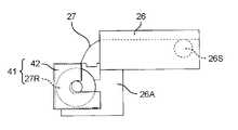
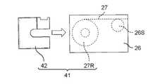
ここで、部品実装装置14が部品BHの供給に使用するキャリアテープ27は、本実施の形態では、ケース入りロール体41から繰り出されるようになっている。ここで「ケース入りロール体41」とは、キャリアテープ27をロール状にしたロール体27Rがケース42に収納されたものをいう(図3も参照)。ケース入りロール体41は、従来用いられているリール付きロール体43(図4)とは異なるものである。ここで「リール付きロール体43」とは、ロール体27Rがリール44により保持されたものをいう。 In this embodiment, the
本実施の形態では、リール付きロール体43のリール44は、図5に示すように、2つの側板45と、2つの側板45の間に配置された巻き芯46を有するものを想定している。本実施の形態では、一方の側板45に巻き芯46が結合されているものとする。そして、一方の側板45の巻き芯46に設けられた複数の凹部46Kと、他方の側板45の側に設けられた複数の凸部45Tとが嵌合することによって、2つの側板45が連結される構成を有しているものとする。このため本実施の形態においてリール44を分解したときは、リール44は、一方の側板45を含む部分と他方の側板45を含む部分とに2分割される。 In this embodiment, it is assumed that the
ここで、ケース入りロール体41のケース42について説明する。ケース42は、図6Aに示すように、左右の側壁51、底壁52、前壁53および後壁54を備えており、上方開口55と後開口56を有している。前壁53の外面には無線タグ42Mが貼り付けられている。後壁54の上部には、一方の側壁51の内面から内方へ張り出した上下の2つの突起ベース51Bが設けられており、2つの突起ベース51Bには、水平方向の外側に向かって突出したテープ先端保持部42Kが設けられている(図6B)。 Here, the
図7A、図7Bに示すように、ケース入りロール体41を保管中或いは運搬中であるときには、キャリアテープ27が有する送り孔27K(スプロケット26Sの外周歯と係合する孔)に、ケース42に設けられたテープ先端保持部42Kを差し込んで係止しておくようにする。なお、ケース入りロール体41を保管中或いは運搬中であるときとは、ケース42にロール体27Rを収納した場合であって、ロール体27Rからキャリアテープ27を引き出して使用する状況にないときを言う。本実施の形態では、2つの送り孔27Kに、ケース42に設けられた2つのテープ先端保持部42Kを差し込んで係止する。これにより保管中或いは運搬中にケース入りロール体41のケース42からキャリアテープ27が抜け出ることが防止され、ひいてはロール体27Rの全体がケース42から脱落することが防止される。 As shown in FIGS. 7A and 7B, when the
一方、ケース入りロール体41からキャリアテープ27を引き出して使用する状況にあるときには、2つのテープ先端保持部42Kをキャリアテープ27の送り孔27Kから取り外し、更には図3に示すように前壁53が下面となるような姿勢にする。このように前壁53が下面となるような姿勢にしてキャリアテープ27を後開口56から引き出すことにより、キャリアテープ27を部品供給ユニット26に送ることが可能となる。このように、ケース42にテープ先端保持部42Kを設けることにより、ケース42におけるキャリアテープ27の先端部の位置が統一されるので、ケース42からキャリアテープ27の先端部を取り出す作業を容易に行うことができる。また、キャリアテープ27の先端部を取り出す作業をロボット等の自動化設備で行わせることにも容易に対応できる。 On the other hand, when the
部品供給ユニット26に対するケース入りロール体41の使用形態としては、例えば、図2の左側に示すケース入りロール体41のように、フィーダ台車25に取り付ける形態のほか、図2の右側および図8Aに示すケース入りロール体41のように、アタッチメント26Aを介して部品供給ユニット26に取り付ける形態がある。或いは、図8Bに示すように、ケース入りロール体41の全体を部品供給ユニット26の内部に収納する形態もある。また或いは、図8Cに示すように、ケース入りロール体41からロール体27Rを取り出し、ロール体27Rのみを部品供給ユニット26の内部に収納する形態もある。 Examples of usage of the cased
このように、本実施の形態において、ケース入りロール体41のケース42には、ロール体27Rを部品供給ユニット26の外部に設置して使用するときにおけるロール体27Rの支持手段の役割(リール付きロール体43におけるリール44の役割)を持たせることができる。 As described above, in the present embodiment, the
次に、キャリアテープ処理装置3について説明する。キャリアテープ処理装置3は、部品実装装置14で使用されるキャリアテープ27を処理してケース入りロール体41を製造する装置である。キャリアテープ処理装置3は、従来のリール付きロール体43のリール44からロール体27Rを取り出し、ロール体27Rをケース42に収納する一方、リール44を回収する構成を有している。 Next, the carrier
図9、図10および図11に示すように、本実施の形態におけるキャリアテープ処理装置3は、リール供給部61、リール搬送部62、ロール体取り出し部63、回収部64、読み取り部65および書き込み部66を備えている。 As shown in FIGS. 9, 10 and 11, the carrier
リール供給部61は、リール付きロール体43を供給する機能を有する。リール供給部61は、図9および図10に示すように、例えば上方に開放した容器状の部材から成り、複数のリール付きロール体43を横方向に並べた状態で保持する。 The
リール搬送部62は、リール供給部61が供給するリール付きロール体43を把持してロール体取り出し部63の上方へ移動させる機能を有する。リール搬送部62は、図9および図10に示すように、把持ヘッド71と把持ヘッド移動機構72を備えている。把持ヘッド71は下方に延びた2つの把持部71Hによって、リール供給部61が供給するリール付きロール体43を把持する。把持ヘッド移動機構72は、リール付きロール体43を把持した把持ヘッド71を水平面内方向および上下方向に移動させる。 The
ロール体取り出し部63は、リール付きロール体43のリール44からロール体27Rを取り出してケース42に収納する機能を有する。ロール体取り出し部63は、リール付きロール体43のリール44からロール体27Rを分離する分離部63Aと、分離部63Aによってリール44から分離されたロール体27Rをケース42に収納するロール体収納部63Bを備えている。 The roll take-out
分離部63Aは、図9および図10に示すように、セパレータ73とセパレータ駆動部74を備えている。セパレータ73は水平方向に対向して上下方向に延びた一対の可動板73Sを有して成る。各可動板73Sには上縁部から下方に窪んで設けられたU字状の逃げ部73Nが設けられている(図10)。 The
図9および図10において、セパレータ駆動部74は、一対の(2つの)アーム部74Aと、2つのアーム部74Aを移動させるアーム駆動部74Bとを備えている。2つのアーム部74Aは、2つの可動板73Sそれぞれに一端部が取り付けられており、それぞれほぼ水平方向に延びている。アーム駆動部74Bは、2つのアーム部74Aを水平方向に移動させることで、2つのアーム部74Aの(従ってセパレータ73の)間隔を変えることができる。 9 and 10, the
図9および図10において、ロール体収納部63Bは、ケース保持部63Baとシュート部63Bbを備えている。ロール体収納部63Bは、空のケース42を保持し、かつ水平方向に搬送する機能を有する。シュート部63Bbは、分離部63Aによってリール44から分離されたロール体27Rが、ケース保持部63Baによって保持された空のケース42に1個ずつ収納されるようにロール体27Rを案内する機能を有する。 9 and 10, the
ケース保持部63Baは、図9、図10および図11に示すように、水平方向に延びたコンベア機構から構成されている。ケース保持部63Baは複数のケース42それぞれを上方開口55が上を向くように一列に並べた状態に保持し、かつ、水平方向に向けて間欠的に搬送する。 As shown in FIGS. 9, 10 and 11, the case holding portion 63Ba is composed of a horizontally extending conveyor mechanism. The case holder 63Ba holds the plurality of
シュート部63Bbは、図9、図10および図11に示すように、一対の(2つの)シュート部材63Tから成る。2つのシュート部材63Tは、セパレータ73を構成する2つの可動板73Sが対向する方向に対向して配置されている。2つのシュート部材63Tは、セパレータ73の下方に配置されている。 As shown in FIGS. 9, 10 and 11, the chute portion 63Bb consists of a pair of (two)
図11において、2つのシュート部材63Tはそれぞれの上端部63Jが上方側にいくほど広がる形状を有している。2つのシュート部材63Tの上端部同士の間隔は、セパレータ73を構成する2つの可動板73Sの下端部同士の間隔よりも広くなっている。また、2つのシュート部材63Tの間隔は、下端側へ行くほど狭くなるようになっている(図11)。 In FIG. 11, the two
シュート部63Bbは、分離部63Aによってリール44が分解されることによってリール44から分離したロール体27Rを下方に案内することによって、その下方に位置するケース42内にロール体27Rを収納する。これにより、ひとつのケース42に1個のロール体27Rが収納される。 The chute portion 63Bb guides downward the
回収部64は、分離部63Aによって分解されたリール44を回収する機能を有する。回収部64は、図9および図10に示すように、一対のリール排出シュート75と回収箱76を備えている。 The
2つのリール排出シュート75は、上側に行くほど開口部が広くなる筒型の形状を有している。2つのリール排出シュート75それぞれの上端開口75Kはセパレータ73の側方(2つの可動板73Sそれぞれの側方)に位置している。回収箱76は上方に開口した容器状の部材であり、2つのリール排出シュート75の下方に設けられている。 The two
分離部63Aによってリール44を分解するときには、先ず、リール搬送部62の把持ヘッド71によって把持されたリール付きロール体43がセパレータ73の上方に位置される(図11)。そして、セパレータ73を構成する2つの可動板73Sの上端部同士の間隔が、リール付きロール体43のリール44を構成する2つの側板45の間の間隔よりも小さくなるようにしたうえで(図12A中に示す矢印A)、2つの可動板73Sそれぞれの上端部が2つの側板45の間に下方から挿入されるように、把持ヘッド71をセパレータ73に対して相対的に下降させる(図12A中に示す矢印B)。 When the
2つの可動板73Sそれぞれの上端部が2つの側板45の間に下方から挿入されたら、アーム駆動部74Bが作動して、2つの可動板73Sの間隔を大きくしていく。このとき2つの可動板73Sの間隔が、2つの側板45の間隔よりも大きくなるようにする(図12B中に示す矢印C)。これにより可動板73Sは側板45を外側に押し広げて側板45とロール体27R間の隙間を広げる。 When the upper ends of the two
2つの可動板73Sの間隔を大きくしていくことによって、側板45とロール体27R間の隙間が広くなったら(図12B)、把持ヘッド71を更に、セパレータ73に対して相対的に下降させる(図12C中に示す矢印D)。これにより2つの可動板73Sはそれぞれ、広げられた側板45とロール体27R間の隙間に挿入される。このとき、各可動板73Sに形成された前述の逃げ部73N内に巻き芯46が入り込む。 When the gap between the
2つの可動板73Sがそれぞれ、側板45とロール体27Rとの間に挿入されたら、アーム駆動部74Bは2つの可動板73Sの間隔を更に広げる(図13中に示す矢印E)。これにより2つの側板45は引き放され、一方の側板45の巻き芯46に設けられた複数の凹部46Kと、他方の側板45の側に設けられた複数の凸部45Tとが分離する(図13)。これによりリール44は一方の側板45を含む部分と他方の側板45を含む部分とに2分割される。リール44から分離したロール体27Rはロール体収納部63Bを構成する2つのシュート部63Bbの間を通ってロール体収納部63Bの直下に位置する空のケース42内に収納される。 After each of the two
一方、2分割されたリール44のうちの一方側の側板45は一方側のリール排出シュート75の上端開口75Kに落下し、他方側の側板45は他方側のリール排出シュート75の上端開口75Kに落下する(図13)。これら2つの側板45はそれぞれリール排出シュート75内を通って落下し、回収箱76内に入って回収される。 On the other hand, the
図9において、読み取り部65は、リール44の外側の表面に印刷(記録)されているバーコードや二次元コード等の識別子(シンボル)を光学的に読み取るリーダやカメラから成り、リール供給部61の近傍に設けられている。識別子は、キャリアテープ27に収納されている部品BHの部品情報を含んでいる。本実施の形態では、読み取り部65は、リール供給部61に保持されているリール付きロール体43のリール44に貼り付けられているコードラベル43L(図9および図10)に印刷されているコードを読み取って部品情報を取得する(読み取る)。図9、図10の破線Brは読み取り部65の読み取り範囲を模式的に示すものである。ここで「部品情報」とは、リール付きロール体43が有するキャリアテープ27に収納されている部品BHに関する情報であり、部品BHの種類、部品名、特性、製造年月日、製造者、使用期限、部品数及びこれらの情報にアクセスするためのアクセス情報(URL等)の少なくともひとつを含んでいればよい。 In FIG. 9, the
このように本実施の形態において、読み取り部65は、キャリアテープ27に収納された部品に関する情報である部品情報を取得する部品情報取得部となっている。なお、リール44が部品情報を記憶した無線タグを有している場合、読み取り部65には無線タグの情報を非接触で読み取る機能を有する非接触リーダを使用してもよい。また、読み取り部65はリール供給部61のリール44から部品情報を読み取るようにしているが、把持ヘッド71に把持されたリール44から読み取るようにしてもよい。また、本実施の形態では読み取り部65がリール供給部61のリール44の識別子を読み取り可能な位置に配置されているが、識別子を読み取り可能な位置であればどこでもよい。また、把持ヘッド71やロボットアーム(図示せず)に装着して移動可能にしてもよい。更に、読み取り部65を無線または有線のハンドスキャナで構成し、作業者OP(図14参照)の操作によってリール44の識別子を読み取るようにしてもよい。 As described above, in the present embodiment, the
書き込み部66は、ケース保持部63Baによって保持されているケース42に取り付けられている無線タグ42Mに情報を無線通信によって書き込む。書き込み部66が無線タグ42Mに書き込む情報は、読み取り部65が取得した(読み取った)部品情報と、識別情報である。 The
ここで「識別情報」とは、部品実装システム1において使用される一のロール体27Rに収納されている部品BHを他のロール体27Rに収納されている部品BHと識別するために使用する情報である。識別情報は、例えば、部品実装システム1が設置される工場内において発行されるシリアル番号によって構成される。本実施の形態では、識別情報は、後述するように、リール44から分離したロール体27Rがケース42に収納される際に、管理コンピュータ6において生成(発行)される。また、識別情報はケース42を管理するための管理情報としても利用される。すなわち、識別情報は、ロール体27Rを識別する目的とケース42を識別する目的の両方で使用される。 Here, "identification information" is information used for distinguishing a component BH stored in one
次に、保管倉庫4について説明する。保管倉庫4は、ケース入りロール体41を保管する。ここでいうケース入りロール体41とは、キャリアテープ処理装置3によって製造されたばかりのケース入りロール体41だけでなく、部品実装装置14において使用されて途中で戻されたような使用途中のケース入りロール体41も含まれる。 Next, the
図14において、保管倉庫4は、筐体81内に複数の棚部82(保管部)を有している。筐体81の前面下方には、入口83が設けられており、筐体81の内部には、入口83を通じて筐体81の外部(作業者OPの手前側)への張り出し動作と筐体81の内部(作業者OPから見た奥側)への引き込み動作とを行う移動テーブル84が設けられている。移動テーブル84は、ケース入りロール体41が保管倉庫4に保管される際には作業者OPの手前側へ張り出され、移動テーブル84に載置されたケース入りロール体41を筐体81内に収容するときには奥側に引き込まれる。 In FIG. 14, the
保管倉庫4が備える複数の棚部82のそれぞれには、ケース入りロール体41を保管(載置)するための複数の保管位置82Sが予め定められている。すなわち本実施の形態において、各棚部82は、ロール体27Rを収納したケース42(すなわちケース入りロール体41)を保管する保管位置82Sを複数備えた保管部となっている。 A plurality of
図14において、筐体81内にはケース移送機構85が設けられている。ケース移送機構85は、上下方向(Z軸方向とする)に延びたZ軸テーブル86と、作業者OPから見た前後方向(Y軸方向とする)に延びてZ軸テーブル86によって上下方向に移動されるY軸テーブル87と、作業者OPから見た横方向(X軸方向とする)に延びてY軸テーブル87によって前後方向に移動されるX軸テーブル88と、X軸テーブル88によってX軸方向に移動される移送ヘッド89とを備えている。 In FIG. 14, a
ケース移送機構85は、Z軸テーブル86によるY軸テーブル87のZ軸方向への移動動作と、Y軸テーブル87によるX軸テーブル88のY軸方向への移動と、X軸テーブル88による移送ヘッド89のX軸方向への移動とによって、移送ヘッド89を三次元的に移動させる。移送ヘッド89はX軸方向に並んだ2つのフィンガ89Fを備えている。 The
位相ヘッド89は、2つのフィンガ89FをX軸方向に互いに近接或いは離間させることができる。2つのフィンガ89Fの間にケース入りロール体41が位置した状態で2つのフィンガ89Fが閉じるように作動されると、ケース入りロール体41は2つのフィンガ89Fによって(すなわち移送ヘッド89によって)把持される。 The
図14において、移送ヘッド89には、撮像視野を作業者OPから見た奥方向に向けた非接触リーダ90が設けられている。非接触リーダ90は、移送ヘッド89がケース入りロール体41を把持する位置において、ケース入りロール体41のケース42に設けられた無線タグ42Mと正対するようになっている。 In FIG. 14, the
非接触リーダ90は、無線タグ42Mと正対した状態において、無線タグ42Mに書き込まれている情報(ロール体27Rに収納されている部品BHの部品情報と識別情報)を無線通信にて読み取る。本実施の形態において、非接触リーダ90は、記憶部としての無線タグ42Mに書き込まれた識別情報を読み取る識別情報読み取り部として機能するようになっている。非接触リーダ90は、ケース入りロール体41の無線タグ42Mに書き込まれている情報を読み取ったら、その読み取った情報を管理コンピュータ6に記憶させる(後述)。 The
複数の棚部82のそれぞれに定められた各保管位置82Sにはユニークな住所が与えられている。本実施の形態では、保管位置82Sにケース入りロール体41を保管(載置)するときには、ケース入りロール体41のロール体27R(キャリアテープ27)に収納されている部品BHの情報(部品情報)と、ケース入りロール体41の識別情報とを関連付けた(いわゆる紐付けした)情報が管理コンピュータ6に記憶される。さらに、部品情報と、保管位置82Sの情報(保管位置情報)とを関連付けた情報が管理コンピュータ6に記憶される(後述)。これにより管理コンピュータ6は、保管倉庫4のどの保管位置82Sに、どの部品BHを収納したケース入りロール体41が保管されているかを把握することができる。 Each
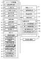
図15は部品実装システム1の全体における制御系統をブロック図により示したものである。図15に示すように、管理コンピュータ6は、生産情報管理部91、部品監視部92、作業指示部93および情報管理部94を備えている。生産情報管理部91は部品実装システム1における生産計画データを記憶している。部品監視部92は、製造ライン2における部品BHの残数等を監視する。部品監視部92は部品切れが予測される場合、その旨を作業指示部93に伝達する。 FIG. 15 is a block diagram showing the overall control system of the
作業指示部93は生産情報管理部91に記憶されている生産計画データに基づく機種の切り替え時の作業指示を、製造ライン2と作業者OPに対して行うとともに、次の機種の生産で使用する部品BHの払い出し等の指示を、保管倉庫4に対して行う。また作業指示部93は、部品監視部92からの情報に基づく作業指示(具体的には、保管倉庫4に対する補充用部品の払い出しの指示と、作業者OPに対する部品補充作業の指示)等を行う。 The
情報管理部94は、第1の情報管理部94a、第2の情報管理部94b、識別情報生成部94cおよび保管位置情報生成部94dを備えている(図15)。第1の情報管理部94aは部品情報を管理し、第2の情報管理部94bは保管倉庫4内における部品BHの保管位置82Sの情報(保管位置情報)を管理する。具体的には、第1の情報管理部94aは、リール44から分離されたロール体27Rについての部品情報と識別情報とを関連付けた状態で記憶する。また、第2の情報管理部94bは、リール44から分離されたロール体27Rについての識別情報と保管位置82Sの情報(保管位置情報)とを関連付けた状態で記憶する。 The
識別情報生成部94cは、キャリアテープ処理装置3がリール付きロール体43のリール44を分解し、リール44からロール体27Rが分離されたとき等に、ロール体27Rについての識別情報を生成(発行)する。保管位置情報生成部94dは、ケース入りロール体41が保管倉庫4に保管される際に、ケース入りロール体41の保管位置82Sを特定して保管位置情報を生成する。 The identification
図15に示すように、キャリアテープ処理装置3は処理装置制御部3Cを備えている。処理装置制御部3Cはキャリアテープ処理装置3が備えるリール搬送部62、ロール体取り出し部63、読み取り部65、書き込み部66等の制御を行う。また図15に示すように、保管倉庫4は倉庫制御部4Cを備えている。倉庫制御部4Cは、保管倉庫4が備える移動テーブル84、ケース移送機構85および非接触リーダ90の制御を行う。 As shown in FIG. 15, the carrier
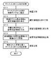
次に、図16に示すフローチャートを用いて、キャリアテープ処理装置3によるケース入りロール体41の製造作業(キャリアテープ27の処理作業)の流れを説明する。先ず、キャリアテープ処理装置3の処理装置制御部3Cは、リール供給部61により供給されるリール付きロール体43のうち、作業対象となっているリール付きロール体43の部品情報を取得する(ステップST1の部品情報取得工程)。ここでは、部品情報の取得は、読み取り部65が、作業対象となっているリール付きロール体43のリール44に貼り付けられているコードラベル43Lの識別子を読み取ることによって行うが(図9)、他の方法によってもよい。例えば、作業者OPが、処理装置制御部3Cに繋がる入力装置(図示せず)から、コードラベル43Lの内容に相当する入力を行うのであってもよい。 Next, the flow of the manufacturing work (processing work of the carrier tape 27) of the cased
ステップST1でリール付きロール体43の部品情報を取得したら、処理装置制御部3Cは、キャリアテープ処理装置3のリール搬送部62を作動させ、作業対象とするリール付きロール体43を把持ヘッド71に把持させる。そして、把持ヘッド71がリール付きロール体43を把持したら、把持ヘッド71を移動させて(図10)、リール付きロール体43をセパレータ73の上方に位置決めする(ステップST2の位置決め工程。図11)。 After obtaining the component information of the reeled
処理装置制御部3Cは、リール付きロール体43をセパレータ73の上方に位置決めしたら、セパレータ73によって前述の要領でリール44を分解し(図12A→図12B→図12C)、ロール体27Rをリール44から分離させる(ステップST3の分離工程)。これによりリール44は一方の側板45を含む部分と他方の側板45を含む部分とに2分割され、ロール体27Rはロール体収納部63Bを通ってロール体収納部63Bの直下に位置する空のケース42内に収納される(ステップST4のロール体収納工程)。また、2分割されたリール44はそれぞれリール排出シュート75内を通って回収箱76に回収される(ステップST5の保持体回収工程)。 After positioning the reeled
ここで、上記ステップST3の分離工程と、ステップST4のロール体収納工程は、リール44からロール体27Rを取り出してケース42に収納するロール体取り出し収納工程となっている。ここで、リール44は、部品BHを収納したキャリアテープ27をロール体27Rの状態で保持する保持体である。このロール体取り出し収納工程のうち、ロール体収納工程では、分離工程でリール44から分離したロール体27Rを空のケース42に1個ずつ収納するようになっている。このため、1個のロール体27Rをひとつのケース42単位で管理することが可能となる。 Here, the separation process of step ST3 and the roll body storage process of step ST4 are the roll body taking-out and storing process of taking out the
処理装置制御部3Cは、ステップST3でリール44を分離させるとき、管理コンピュータ6の識別情報生成部94cに、リール44から分離されたロール体27Rについての識別情報の生成を要請する。そして、処理装置制御部3Cから識別情報の生成を要請された識別情報生成部94cは、リール44の分離によって取り出されたロール体27Rについての識別情報を生成する(ステップST6の識別情報生成工程)。 When the
ステップST6で識別情報生成部94cによって識別情報が生成されたら、キャリアテープ処理装置3の処理装置制御部3Cは、その生成された識別情報を受け取る。そして、書き込み部66によって、ステップST1で取得した部品情報と、ステップST6で生成された識別情報を、ケース42(ステップST4でロール体27Rが収納されたケース42)に取り付けられている無線タグ42Mに書き込む(ステップST7の書き込み工程)。 After the identification information is generated by the identification
処理装置制御部3Cは、部品情報と識別情報をケース42の無線タグ42Mに書き込んだら、無線タグ42Mに書き込んだ情報(ロール体27Rについての部品情報および識別情報)を管理コンピュータ6に送信し、管理コンピュータ6の第1の情報管理部94aに、その情報(部品情報および識別情報)を記憶させる。これにより、リール44から分離されたロール体27Rについて、ロール体27Rの固有の情報である識別情報と、ロール体27Rに収納されている部品BHの情報である部品情報とが関連付けられた状態で管理コンピュータ6に登録される(ステップST8の部品情報登録工程)。 After writing the part information and the identification information to the
処理装置制御部3Cは、ロール体27Rについての情報を管理コンピュータ6の第1の情報管理部94aに書き込んだら、キャリアテープ処理装置3によるケース入りロール体41の製造(キャリアテープ27の処理作業)を終了する。 After writing the information about the
次に、図17に示すフローチャートを用いて、ケース入りロール体41の保管作業の流れを説明する。先ず、保管倉庫4の倉庫制御部4Cが、筐体81に設けられた入口83から移動テーブル84を手前側に移動させる。そして、作業者OPが(あるいは図示しない移動ロボットが)、移動テーブル84にケース入りロール体41を載置する(ステップST11の載置工程。図14)。このときケース入りロール体41は、上方開口55が上を向き、かつ、前壁53が手前側(作業者OPの側)を向く姿勢で移動テーブル84に載置される。これによりケース42に設けられた無線タグ42Mは、手前側を向いた状態となる(図14)。 Next, the flow of storage work for the
移動テーブル84にケース入りロール体41が載置されたら、倉庫制御部4Cは移動テーブル84を移動させて、ケース入りロール体41を筐体81内に引き込む。ケース入りロール体41が筐体81内に引き込まれたら、倉庫制御部4Cは移動テーブル84に載置されているケース入りロール体41の手前側に移送ヘッド89を移動させる。そして、2つのフィンガ89Fを閉じるように作動させて、移送ヘッド89にケース入りロール体41を把持させる。このとき移送ヘッド89に設けられた非接触リーダ90はケース入りロール体41のケース42に設けられた無線タグ42Mと正対し、非接触リーダ90は無線タグ42Mに書き込まれている識別情報を読み取る(ステップST12の識別情報読み取り工程)。 After the
非接触リーダ90が無線タグ42Mに書き込まれている識別情報を読み取ったら、倉庫制御部4Cは、非接触リーダ90が読み取った識別情報を管理コンピュータ6に送信する。そして、倉庫制御部4Cから識別情報の送信を受けた管理コンピュータ6は、保管位置情報生成部94dにおいて、その識別情報に対応するケース入りロール体41(非接触リーダ90が識別情報を読み取ったケース入りロール体41)の保管倉庫4内における保管位置82Sを特定して保管位置情報を生成する(ステップST13の保管位置情報生成工程)。保管位置82Sの特定は、その時点で空き状態となっている保管位置82Sの中から任意に或いは所定の規則に従って選択してなされる。 After the
ステップST13で保管位置情報生成部94dが保管位置情報を生成したら、管理コンピュータ6は、その生成された保管位置情報と、その保管位置情報に対応するケース入りロール体41の識別情報とを関連付けた状態で、第2の情報管理部94bに記憶させる。これにより、保管倉庫4に保管されようとしているケース入りロール体41について、ロール体27Rの固有の情報である識別情報と、ロール体27Rを含むケース入りロール体41の保管倉庫4内での保管位置の情報(保管位置情報)とが関連付けられた状態で管理コンピュータ6に登録される(ステップST14の保管位置情報登録工程)。 When the storage position
管理コンピュータ6は、移動テーブル84に載置されたケース入りロール体41についての保管情報と識別情報とを関連付けた状態で第2の情報管理部94bに記憶させたら、ケース移送機構85を作動させて、移動テーブル84に載置されたケース入りロール体41を、保管位置情報に対応する保管位置82Sに移送して保管する(ステップST15の保管工程)。これによりケース入りロール体41の保管作業が終了する。 When the
このように本実施の形態では、ロール体27Rをリール44のような保持体から取り出してケース42に収納し、ロール体27Rをケース入りロール体41として取り扱うことができるようになっている。ケース入りロール体41はリール付きロール体43よりも幅方向寸法を小さくしてコンパクト化を図ることができるうえ、ロール体27Rを(すなわちキャリアテープ27を)使い切った後にリール44が廃棄物として残らないので作業性もよい。また、ケース42はそれ自体が安価であるだけでなく、リール44と異なって再使用(使い回し)ができるので、その面でもコストを安価にすることができる。 As described above, in the present embodiment, the
更に、本実施の形態では、ケース42に部品情報を記憶させることができる記憶部としての無線タグ42Mが設けられており、リール44に記録されていた部品情報を無線タグ42Mに書き込んで記憶させることができる。したがって、ロール体27Rをリール44から取り出しても部品情報を失わず、ケース入りロール体41ひとつひとつの単位で部品情報を管理することができる。また、部品情報とロール体27Rの固有の情報である識別情報が関連付けられて記憶されるので、ケース入りロール体41ひとつひとつの単位で部品情報を管理することが可能である。 Furthermore, in the present embodiment, the
上述の部品実装システム1において、キャリアテープ処理装置3(処理装置制御部3C、リール搬送部62、ロール体取り出し部63、部品情報取得部としての読み取り部65、書き込み部66)、保管倉庫4(倉庫制御部4C、棚部82、ケース移送機構85、識別情報読み取り部としての非接触リーダ90)、情報管理部94(第1の情報管理部94a、第2の情報管理部94b、識別情報生成部94cおよび保管位置情報生成部94d)は部品管理装置100を構成している(図15)。 In the
部品管理装置100を用いた部品BHの管理作業(部品管理方法)は、先ず、部品情報を取得し(部品情報取得工程)、識別情報を生成したうえで(識別情報生成工程)、これら部品情報と識別情報をケース42に設けられた無線タグ42Mに書き込み(書き込み工程)、その書き込んだ部品情報と識別情報とを関連付けて第1の情報管理部94aに記憶させる(部品情報登録工程)。そして、無線タグ42Mに書き込んだ識別情報を識別情報読み取り部(非接触リーダ90)によって読み取り(識別情報読み取り工程)、保管位置82Sを特定して保管位置情報を生成したうえで(保管位置情報生成工程)、識別情報と保管位置情報とを関連付けて第2の情報管理部94bに記憶させる(保管位置情報登録工程)という手順で実行される。 The management work (parts management method) of the parts BH using the
このような部品管理方法によれば、ケース入りロール体41についての部品情報と識別情報が関連付けて記憶されるほか、ケース入りロール体41の識別情報と保管位置情報とが関連付けて記憶されるので、保管倉庫4におけるケース入りロール体41の保管および取り出しをスムーズに行うことができる。このため本実施の形態における部品管理装置100(部品管理方法)によれば、部品BHの入庫および出庫を簡単かつ効率よく行うことができる。 According to this parts management method, the part information and the identification information about the cased
なお、本実施の形態における部品管理装置100が取り扱うケース入りロール体41のロール体27Rは、必ずしもリール付きロール体43から取り出されたものである必要はなく、初めからキャリアテープ27のロール体27Rとして製造されたものあってもよい。例えば、リール付きロール体43を製造する際のもととなる大容量のキャリアテープのロール体から長さを計量しながら巻回して製造したようなロール体27Rであってもよい。 It should be noted that the
図18は、本実施の形態における部品実装システム1におけるケース入りロール体41の運用のイメージを図示したものである。この図に示すように、本実施の形態におけるケース入りロール体41は、リール付きロール体43とケース42がキャリアテープ処理装置3に供給されることで製造される。キャリアテープ処理装置3で製造されたケース入りロール体41の一部は製造ライン2に送られて使用され、他の一部は保管倉庫4に保管(入庫)される。保管倉庫4に保管されたケース入りロール体41は、そこから出庫されて製造ライン2に送られ、使用される。そして、製造ライン2でケース入りロール体41のキャリアテープ27が使い切られることによって生じたケース42は回収されてキャリアテープ処理装置3に供給され、新たなケース入りロール体41の製造に再利用される。また、製造ライン2に送られたケース入りロール体41であって、キャリアテープ27がまだ使い切られていない状態のものの一部は、保管倉庫4に戻されて保管(入庫)される。 FIG. 18 illustrates an image of operation of the cased
以上説明したように、本実施の形態のおけるキャリアテープ処理装置3(キャリアテープ処理方法)では、ロール体27Rをリール44のような保持体から取り出してケース42に収納し、ロール体27Rをケース入りロール体41として取り扱うことができるようになっている。ケース入りロール体41はリール付きロール体43よりも幅方向寸法を小さくしてコンパクト化を図ることができるうえ、ロール体27Rを(すなわちキャリアテープ27を)使い切った後にリール44が廃棄物として残らないので作業性もよい。 As described above, in the carrier tape processing apparatus 3 (carrier tape processing method) according to the present embodiment, the
また、ケース42はそれ自体が安価であるだけでなく、リール44と異なって再使用(使い回し)ができるので、その面でもコストを安価にすることができる。このため本実施の形態におけるキャリアテープ処理装置3(キャリアテープ処理方法)によれば、安価な構成でリールなしの部品供給形態を実現できる。 In addition, the
更に、本実施の形態では、ケース42に部品情報を記憶させることができる記憶部としての無線タグ42Mが設けられており、リール44に記録されていた部品情報を無線タグ42Mに書き込んで記憶させることができるので、ロール体27Rをリール44から取り出しても部品情報を失わず、ケース入りロール体41ひとつひとつの単位で部品情報を管理することができる。また、部品情報とロール体27Rの固有の情報である識別情報が関連付けられて記憶されるので、ケース入りロール体41ひとつひとつの単位で部品情報を管理することが可能である。このため本実施の形態におけるキャリアテープ処理装置3(キャリアテープ処理方法)によれば、部品情報を管理しつつ、安価な構成でリールなしの部品供給形態を実現できる。 Furthermore, in the present embodiment, the
これまで本開示の実施の形態について説明してきたが、本開示は上述したものに限定されず、種々の変形等が可能である。例えば、上述の実施の形態では、リール付きロール体43のリール44は2分割されるようになっていたが、これは一例であり、3つ以上のパーツに分割されるのであってもよい。この場合であっても、分解によって生じた複数のパーツのそれぞれがリール排出シュート75を通って回収箱76に落下するようにすればよく、これにより分解されたリール44を確実に回収することができる。 Although the embodiments of the present disclosure have been described so far, the present disclosure is not limited to the above, and various modifications and the like are possible. For example, in the above-described embodiment, the
また、上述の実施の形態で示したリール44の分解手段の構成および分解の方法は一例であり、他の方法によって分解してリール44からロール体27Rを取り出すようにしてもよい。更には、リール44を分解しなくてもリール44を取り外すことができる構成(例えばリール44の側板45が1枚であり、1枚の側板45から巻き芯46が片持ち状態で延びていて、巻き芯46からロール体27Rを抜き取ればリール44からロール体27Rを分離できる構成)であるのであれば、必ずしもリール44を分解する必要はない。更には、上述の実施の形態において示したロール体取り出し部63の具体的構成は例示に過ぎず、部品BHを収納したキャリアテープ27をロール体27Rの状態で保持するリール44のような保持体からロール体27Rを取り出してケース42に収納することができれば、その構成は自由である。 Further, the configuration of the disassembling means for the
安価な構成でリールなしの部品供給形態を実現できるキャリアテープ処理装置およびキャリアテープ処理方法を提供する。 To provide a carrier tape processing apparatus and a carrier tape processing method capable of realizing a component supply form without a reel with an inexpensive configuration.
3 キャリアテープ処理装置
27 キャリアテープ
27R ロール体
41 ケース入りロール体
42 ケース
42M 無線タグ(記憶部)
43 リール付きロール体
44 リール(保持体)
45 側板
46 巻き芯
63 ロール体取り出し部
63A 分離部
63B ロール体収納部
63Ba ケース保持部
63Bb シュート部
64 回収部
65 読み取り部(部品情報取得部)
66 書き込み部
82 棚部(保管部)
94 情報管理部
94a 第1の情報管理部
94b 第2の情報管理部
94c 識別情報生成部
94d 保管位置情報生成部
BH 部品3 carrier
43 roll body with
45
66
94
Claims (24)
Translated fromJapanese前記保持体から前記ロール体を分離する分離部と、
前記分離部によって前記保持体から分離された前記ロール体を前記ケースに収納するロール体収納部と、を有する請求項1に記載のキャリアテープ処理装置。The roll body removing section is
a separation unit that separates the roll body from the holding body;
2. The carrier tape processing apparatus according to claim 1, further comprising: a roll storage section for storing the roll separated from the holder by the separation section in the case.
空のケースを保持するケース保持部と、
前記分離部によって前記保持体から分離された前記ロール体を前記ケース保持部によって保持された前記空のケースに1個ずつ収納するシュート部と、を備えた請求項2に記載のキャリアテープ処理装置。The roll body storage section is
a case holder for holding an empty case;
3. The carrier tape processing apparatus according to claim 2, further comprising a chute section for storing the roll bodies separated from the holder by the separation section one by one in the empty case held by the case holding section. .
前記分離部は、前記保持体を一方の側板を含む部分と他方の側板を含む部分とに2分割して分解する請求項2に記載のキャリアテープ処理装置。The holding body comprises a reel having a winding core around which the carrier tape is wound and a pair of side plates sandwiching the winding core,
3. The carrier tape processing apparatus according to claim 2, wherein the separation unit divides the holding body into two parts, one including one side plate and the other including the side plate, and disassembles them.
前記保持体から前記ロール体を分離する分離工程と、
前記分離工程で前記保持体から分離した前記ロール体を前記ケースに収納するロール体収納工程と、を含む請求項7に記載のキャリアテープ処理方法。The roll body taking out and storing step includes:
a separation step of separating the roll body from the holding body;
8. The carrier tape processing method according to claim 7, further comprising a roll housing step of housing the roll separated from the holder in the separating step in the case.
前記分離工程は、前記保持体を一方の側板を含む部分と他方の側板を含む部分とに2分割して分解する請求項8に記載のキャリアテープ処理方法。The holding body comprises a reel having a winding core around which the carrier tape is wound and a pair of side plates sandwiching the winding core,
9. The carrier tape processing method according to claim 8, wherein the separating step disassembles the holder by dividing it into a portion including one side plate and a portion including the other side plate.
前記部品に関する情報である部品情報を取得する部品情報取得部と、
前記部品情報取得部により取得された前記部品情報を前記記憶部に書き込む書き込み部とを備えたキャリアテープ処理装置。a roll take-out unit for taking out the roll body from a holding body that holds a carrier tape containing components in a roll state and storing the roll body in a case having a storage part;
a parts information acquisition unit that acquires parts information that is information about the parts;
A carrier tape processing apparatus comprising: a writing unit that writes the component information acquired by the component information acquisition unit into the storage unit.
前記書き込み部は、前記部品情報とともに前記識別情報を書き込む請求項13に記載のキャリアテープ処理装置。Furthermore, an identification information generation unit that generates identification information used to identify the component from components stored in other cases,
14. The carrier tape processing apparatus according to claim 13, wherein the writing unit writes the identification information together with the component information.
前記部品に関する情報である部品情報を前記記憶部に書き込む書き込み工程とを含むキャリアテープ処理方法。a roll taking out and storing step of taking out the roll body from a holding body that holds the carrier tape containing the components in a roll body state and storing the roll body in a case having a storage unit;
and a writing step of writing component information, which is information about the component, into the storage unit.
前記書き込み工程では、前記部品情報とともに前記識別情報を書き込む請求項20に記載のキャリアテープ処理方法。Furthermore, including an identification information generation step of generating identification information used to identify the component from components stored in other cases,
21. The carrier tape processing method according to claim20 , wherein in said writing step, said identification information is written together with said component information.
Applications Claiming Priority (5)
| Application Number | Priority Date | Filing Date | Title |
|---|---|---|---|
| JP2020053534 | 2020-03-25 | ||
| JP2020053534 | 2020-03-25 | ||
| JP2020053536 | 2020-03-25 | ||
| JP2020053536 | 2020-03-25 | ||
| PCT/JP2021/001952WO2021192557A1 (en) | 2020-03-25 | 2021-01-21 | Carrier tape processing device and carrier tape processing method |
Publications (2)
| Publication Number | Publication Date |
|---|---|
| JPWO2021192557A1 JPWO2021192557A1 (en) | 2021-09-30 |
| JP7113184B2true JP7113184B2 (en) | 2022-08-05 |
Family
ID=77890094
Family Applications (1)
| Application Number | Title | Priority Date | Filing Date |
|---|---|---|---|
| JP2021535621AActiveJP7113184B2 (en) | 2020-03-25 | 2021-01-21 | Carrier tape processing device and carrier tape processing method |
Country Status (5)
| Country | Link |
|---|---|
| US (1) | US12404135B2 (en) |
| JP (1) | JP7113184B2 (en) |
| CN (1) | CN115211247B (en) |
| DE (1) | DE112021001834T5 (en) |
| WO (1) | WO2021192557A1 (en) |
Families Citing this family (2)
| Publication number | Priority date | Publication date | Assignee | Title |
|---|---|---|---|---|
| WO2024029357A1 (en)* | 2022-08-01 | 2024-02-08 | パナソニックIpマネジメント株式会社 | Component supply system, arrangement determination method, control method, management device, and supply robot |
| JP7394429B1 (en)* | 2022-08-01 | 2023-12-08 | パナソニックIpマネジメント株式会社 | Parts supply system, placement determination method, control method, management device and supply robot |
Citations (6)
| Publication number | Priority date | Publication date | Assignee | Title |
|---|---|---|---|---|
| JP2005119880A (en) | 2004-10-14 | 2005-05-12 | Shin Etsu Polymer Co Ltd | Tape winding device |
| JP2006114764A (en) | 2004-10-15 | 2006-04-27 | Murata Mfg Co Ltd | Packaged electronic component and electronic component mounter |
| JP2018507558A (en) | 2015-02-19 | 2018-03-15 | マイクロニック アーベーMycronic Ab | Method, system and device for providing information on a display arranged on a carrier of a surface mount technology system |
| JP2018520059A (en) | 2015-05-28 | 2018-07-26 | マイクロニック アーベーMycronic Ab | Smart containers and / or boxes handled by and housed in automated SMD warehouses |
| JP2019091771A (en) | 2017-11-13 | 2019-06-13 | Juki株式会社 | Component management system |
| WO2020202737A1 (en) | 2019-03-29 | 2020-10-08 | パナソニックIpマネジメント株式会社 | Carrier tape holding device, holder, and carrier tape package body |
Family Cites Families (45)
| Publication number | Priority date | Publication date | Assignee | Title |
|---|---|---|---|---|
| US4955471A (en)* | 1987-09-05 | 1990-09-11 | Konica Corporation | Packaging structure for a ring-shaped product |
| JPH04173584A (en)* | 1990-10-24 | 1992-06-22 | Murata Mfg Co Ltd | Package for chip-shaped electronic component |
| JPH0521990A (en) | 1991-07-17 | 1993-01-29 | Matsushita Electric Ind Co Ltd | Electronic component assembly and supply device for electronic component assembly |
| JPH05139479A (en)* | 1991-11-13 | 1993-06-08 | Dainippon Printing Co Ltd | Carrier tape roll |
| US5364045A (en)* | 1993-06-07 | 1994-11-15 | Motorola, Inc. | Method and apparatus for dispensing electronic components |
| MY112708A (en)* | 1993-09-07 | 2001-08-30 | Lintec Corp | Tape winding apparatus and tape |
| US5454900A (en)* | 1994-08-10 | 1995-10-03 | Telford Industries Pte Ltd. | Detaping apparatus |
| JPH11180649A (en)* | 1997-12-25 | 1999-07-06 | Tenryu Technics:Kk | Device and method for widing cover tape for taping member |
| US6206198B1 (en)* | 1998-08-11 | 2001-03-27 | Texas Instruments Incorporated | Lightweight, high temperature packing reel for integrated circuits |
| JP2000208988A (en)* | 1999-01-14 | 2000-07-28 | Matsushita Electric Ind Co Ltd | Electronic component supply device |
| JP2002096974A (en)* | 2000-09-22 | 2002-04-02 | Oki Electric Ind Co Ltd | Conveying reel, conveying method using it, and method of manufacturing electronic device |
| US6817216B2 (en)* | 2002-08-22 | 2004-11-16 | Accu-Assembly Incorporated | Electronic component placement |
| US7571539B2 (en)* | 2003-08-26 | 2009-08-11 | Panasonic Corporation | Component verification method and apparatus |
| EP1796453A1 (en)* | 2004-09-28 | 2007-06-13 | Matsushita Electric Industrial Co., Ltd. | Maintenance method and component mounter |
| CN101167417B (en) | 2005-05-23 | 2010-08-18 | 松下电器产业株式会社 | Electronic component tape packaging and electronic component feeding equipment |
| JP4934583B2 (en)* | 2007-12-25 | 2012-05-16 | 富士機械製造株式会社 | Component information detection system and component information detection method for component supply device in electronic component mounting apparatus |
| JP5924816B2 (en)* | 2012-07-05 | 2016-05-25 | Jukiオートメーションシステムズ株式会社 | Component supply device, component mounting device, component supply method, and substrate manufacturing method |
| DE102012016479B4 (en)* | 2012-08-17 | 2016-11-03 | Suba Holding Gmbh + Co.Kg | Device for winding strip-shaped material onto bobbins |
| JP5909650B2 (en)* | 2012-10-23 | 2016-04-27 | パナソニックIpマネジメント株式会社 | Electronic component mounting system |
| WO2015040081A1 (en)* | 2013-09-18 | 2015-03-26 | Mycronic AB | Method, system and device for identifying a pallet in an smt system |
| JP6195784B2 (en)* | 2013-11-22 | 2017-09-13 | 株式会社 東京ウエルズ | Carrier tape take-up and storage device and carrier tape take-up and storage method |
| JP6630914B2 (en)* | 2015-07-29 | 2020-01-15 | パナソニックIpマネジメント株式会社 | Component supply system and component supply method |
| JP6561317B2 (en)* | 2016-06-01 | 2019-08-21 | パナソニックIpマネジメント株式会社 | Component mounting system |
| DE202016103393U1 (en)* | 2016-06-27 | 2017-09-28 | Kuka Systems Gmbh | Gripping tool and gripping device |
| CN206155857U (en)* | 2016-09-29 | 2017-05-10 | 黄民清 | Carrier band packaging all -in -one machine |
| JP6496908B2 (en)* | 2016-10-28 | 2019-04-10 | パナソニックIpマネジメント株式会社 | Component mounting system |
| JP2018107376A (en)* | 2016-12-28 | 2018-07-05 | パナソニックIpマネジメント株式会社 | Tape reel support device, component mounting device, and tape reel support method |
| US10373643B2 (en)* | 2017-03-27 | 2019-08-06 | Panasonic Intellectual Property Management Co., Ltd. | Component accommodating body managing apparatus, component accommodating body storeroom, and component storage instructing method |
| CN208326024U (en)* | 2017-09-15 | 2019-01-04 | 张志陆 | Rectilinear storage box structure |
| CN111868905A (en)* | 2018-03-15 | 2020-10-30 | 巨友技术有限公司 | Automatic output roll changer |
| ES2826876T3 (en)* | 2018-04-20 | 2021-05-19 | Desarrollo De Maqu Y Soluciones Automaticas S L | Procedure and device for continuous loading, unloading and winding of product on a reel |
| EP3784611A1 (en)* | 2018-04-26 | 2021-03-03 | I.M.A. Industria Macchine Automatiche S.p.A. | Method for reel changing in automatic machines |
| CN112772012B (en)* | 2018-10-15 | 2022-08-09 | 松下知识产权经营株式会社 | Mounting substrate manufacturing system, component mounting system, and storage body transfer method |
| EP4116247A4 (en)* | 2020-03-03 | 2023-04-12 | Fuji Corporation | Wind-up drum, tape feeder, and component mounting machine |
| JP7356574B2 (en)* | 2020-03-18 | 2023-10-04 | 株式会社Fuji | Reel attachment/detachment device |
| US20230114399A1 (en)* | 2020-03-25 | 2023-04-13 | Panasonic Intellectual Property Management Co., Ltd. | Component mounting system and method for handling carrier tape roll body |
| CN119967798A (en)* | 2020-03-25 | 2025-05-09 | 松下知识产权经营株式会社 | Carrier tape processing device and carrier tape processing method |
| CN120207812A (en)* | 2020-03-25 | 2025-06-27 | 松下知识产权经营株式会社 | Component management device and component management method |
| US12180031B2 (en)* | 2020-07-07 | 2024-12-31 | Practical Solution Pte Ltd | Winding apparatus and a method of winding a product strip onto a reel |
| WO2022158077A1 (en)* | 2021-01-21 | 2022-07-28 | パナソニックIpマネジメント株式会社 | Component loading device |
| US12439574B2 (en)* | 2021-01-21 | 2025-10-07 | Panasonic Intellectual Property Management Co., Ltd. | Housing device |
| CN115072447A (en)* | 2021-03-11 | 2022-09-20 | 泰科电子(上海)有限公司 | Material belt processing system |
| CN116654427A (en)* | 2022-02-18 | 2023-08-29 | 太原富驰科技有限公司 | material carrying device |
| US12195289B2 (en)* | 2022-06-24 | 2025-01-14 | Te Connectivity Solutions Gmbh | Reel handling machine |
| CN117429671A (en)* | 2022-07-14 | 2024-01-23 | 泰科电子(上海)有限公司 | Product packaging tape coiling device and product packaging system |
- 2021
- 2021-01-21USUS17/904,858patent/US12404135B2/enactiveActive
- 2021-01-21WOPCT/JP2021/001952patent/WO2021192557A1/ennot_activeCeased
- 2021-01-21JPJP2021535621Apatent/JP7113184B2/enactiveActive
- 2021-01-21CNCN202180017833.7Apatent/CN115211247B/enactiveActive
- 2021-01-21DEDE112021001834.5Tpatent/DE112021001834T5/enactivePending
Patent Citations (6)
| Publication number | Priority date | Publication date | Assignee | Title |
|---|---|---|---|---|
| JP2005119880A (en) | 2004-10-14 | 2005-05-12 | Shin Etsu Polymer Co Ltd | Tape winding device |
| JP2006114764A (en) | 2004-10-15 | 2006-04-27 | Murata Mfg Co Ltd | Packaged electronic component and electronic component mounter |
| JP2018507558A (en) | 2015-02-19 | 2018-03-15 | マイクロニック アーベーMycronic Ab | Method, system and device for providing information on a display arranged on a carrier of a surface mount technology system |
| JP2018520059A (en) | 2015-05-28 | 2018-07-26 | マイクロニック アーベーMycronic Ab | Smart containers and / or boxes handled by and housed in automated SMD warehouses |
| JP2019091771A (en) | 2017-11-13 | 2019-06-13 | Juki株式会社 | Component management system |
| WO2020202737A1 (en) | 2019-03-29 | 2020-10-08 | パナソニックIpマネジメント株式会社 | Carrier tape holding device, holder, and carrier tape package body |
Also Published As
| Publication number | Publication date |
|---|---|
| JPWO2021192557A1 (en) | 2021-09-30 |
| DE112021001834T5 (en) | 2023-01-12 |
| US20230111399A1 (en) | 2023-04-13 |
| CN115211247A (en) | 2022-10-18 |
| US12404135B2 (en) | 2025-09-02 |
| CN115211247B (en) | 2025-03-11 |
| WO2021192557A1 (en) | 2021-09-30 |
Similar Documents
| Publication | Publication Date | Title |
|---|---|---|
| JP7336645B2 (en) | PARTS MANAGEMENT DEVICE AND PARTS MANAGEMENT METHOD | |
| JP7113184B2 (en) | Carrier tape processing device and carrier tape processing method | |
| JP2011199217A (en) | Feeder management method and component mounting apparatus | |
| CN112106460B (en) | Parts storage number management system and parts storage number management method | |
| JP2022140485A (en) | Carrier tape processing device and carrier tape processing method | |
| US20250203835A1 (en) | Kitting device extraction system | |
| US20230114399A1 (en) | Component mounting system and method for handling carrier tape roll body | |
| JP7542210B2 (en) | Carrier tape processing device and carrier tape processing method | |
| JP7403045B2 (en) | Carrier tape roll manufacturing device and carrier tape roll manufacturing method | |
| JP7470907B2 (en) | Component mounting system and method for processing carrier tape roll body | |
| JP2021153152A (en) | Carrier tape roll body | |
| JP2021064697A (en) | Nozzle management device | |
| JP7570048B2 (en) | Pallet storage device and tray parts management system | |
| WO2025109715A1 (en) | Work guidance apparatus and work guidance method | |
| WO2023139789A1 (en) | Preparation device, mounting device, mounting system, and information processing method | |
| JP2022118203A (en) | Component type management device | |
| JP2021064693A (en) | Nozzle management device |
Legal Events
| Date | Code | Title | Description |
|---|---|---|---|
| A621 | Written request for application examination | Free format text:JAPANESE INTERMEDIATE CODE: A621 Effective date:20210622 | |
| A871 | Explanation of circumstances concerning accelerated examination | Free format text:JAPANESE INTERMEDIATE CODE: A871 Effective date:20210908 | |
| A131 | Notification of reasons for refusal | Free format text:JAPANESE INTERMEDIATE CODE: A131 Effective date:20220105 | |
| A521 | Request for written amendment filed | Free format text:JAPANESE INTERMEDIATE CODE: A523 Effective date:20220210 | |
| TRDD | Decision of grant or rejection written | ||
| A01 | Written decision to grant a patent or to grant a registration (utility model) | Free format text:JAPANESE INTERMEDIATE CODE: A01 Effective date:20220405 | |
| A61 | First payment of annual fees (during grant procedure) | Free format text:JAPANESE INTERMEDIATE CODE: A61 Effective date:20220418 | |
| R151 | Written notification of patent or utility model registration | Ref document number:7113184 Country of ref document:JP Free format text:JAPANESE INTERMEDIATE CODE: R151 |