JP7112100B2 - Electrosurgical device with flexible shaft - Google Patents
Electrosurgical device with flexible shaftDownload PDFInfo
- Publication number
- JP7112100B2 JP7112100B2JP2019541109AJP2019541109AJP7112100B2JP 7112100 B2JP7112100 B2JP 7112100B2JP 2019541109 AJP2019541109 AJP 2019541109AJP 2019541109 AJP2019541109 AJP 2019541109AJP 7112100 B2JP7112100 B2JP 7112100B2
- Authority
- JP
- Japan
- Prior art keywords
- flexible
- tube
- electrosurgical
- housing
- tip
- Prior art date
- Legal status (The legal status is an assumption and is not a legal conclusion. Google has not performed a legal analysis and makes no representation as to the accuracy of the status listed.)
- Active
Links
- 239000007789gasSubstances0.000claimsdescription136
- 239000000919ceramicSubstances0.000claimsdescription39
- 238000005520cutting processMethods0.000claimsdescription27
- 239000011261inert gasSubstances0.000claimsdescription25
- 239000004020conductorSubstances0.000claimsdescription9
- 239000000463materialSubstances0.000claimsdescription7
- 230000008602contractionEffects0.000claimsdescription2
- 230000015271coagulationEffects0.000description43
- 238000005345coagulationMethods0.000description43
- 210000002381plasmaAnatomy0.000description36
- 210000001519tissueAnatomy0.000description32
- 230000005495cold plasmaEffects0.000description30
- 238000000034methodMethods0.000description12
- XKRFYHLGVUSROY-UHFFFAOYSA-NArgonChemical compound[Ar]XKRFYHLGVUSROY-UHFFFAOYSA-N0.000description10
- 230000000694effectsEffects0.000description10
- 239000001307heliumSubstances0.000description8
- 229910052734heliumInorganic materials0.000description8
- SWQJXJOGLNCZEY-UHFFFAOYSA-Nhelium atomChemical compound[He]SWQJXJOGLNCZEY-UHFFFAOYSA-N0.000description8
- 238000001356surgical procedureMethods0.000description7
- 238000010586diagramMethods0.000description6
- 230000006870functionEffects0.000description6
- 238000003780insertionMethods0.000description6
- 230000037431insertionEffects0.000description6
- 230000007246mechanismEffects0.000description6
- 239000002184metalSubstances0.000description6
- 229910052751metalInorganic materials0.000description6
- 238000002679ablationMethods0.000description5
- 229910052786argonInorganic materials0.000description5
- 239000012530fluidSubstances0.000description5
- 239000007921spraySubstances0.000description5
- 238000005452bendingMethods0.000description4
- 238000004891communicationMethods0.000description4
- 230000023597hemostasisEffects0.000description4
- 239000011248coating agentSubstances0.000description3
- 238000000576coating methodMethods0.000description3
- 238000001816coolingMethods0.000description3
- 230000006378damageEffects0.000description3
- 238000005516engineering processMethods0.000description3
- 239000011810insulating materialSubstances0.000description3
- 239000012811non-conductive materialSubstances0.000description3
- 229910001220stainless steelInorganic materials0.000description3
- 239000010935stainless steelSubstances0.000description3
- 230000001954sterilising effectEffects0.000description3
- 238000004659sterilization and disinfectionMethods0.000description3
- 238000004804windingMethods0.000description3
- 239000004696Poly ether ether ketoneSubstances0.000description2
- 239000004809TeflonSubstances0.000description2
- 229920006362Teflon®Polymers0.000description2
- 208000027418Wounds and injuryDiseases0.000description2
- 238000005253claddingMethods0.000description2
- 230000008878couplingEffects0.000description2
- 238000010168coupling processMethods0.000description2
- 238000005859coupling reactionMethods0.000description2
- 238000007667floatingMethods0.000description2
- 230000002496gastric effectEffects0.000description2
- 239000012212insulatorSubstances0.000description2
- 150000002500ionsChemical class0.000description2
- 238000003698laser cuttingMethods0.000description2
- 229910052756noble gasInorganic materials0.000description2
- 229920002530polyetherether ketonePolymers0.000description2
- 238000003825pressingMethods0.000description2
- 230000004044responseEffects0.000description2
- 229920000431shape-memory polymerPolymers0.000description2
- 239000010963304 stainless steelSubstances0.000description1
- RYGMFSIKBFXOCR-UHFFFAOYSA-NCopperChemical compound[Cu]RYGMFSIKBFXOCR-UHFFFAOYSA-N0.000description1
- MYMOFIZGZYHOMD-UHFFFAOYSA-NDioxygenChemical compoundO=OMYMOFIZGZYHOMD-UHFFFAOYSA-N0.000description1
- 206010051814EscharDiseases0.000description1
- 206010028980NeoplasmDiseases0.000description1
- 235000014676Phragmites communisNutrition0.000description1
- 229910000589SAE 304 stainless steelInorganic materials0.000description1
- 210000001015abdomenAnatomy0.000description1
- 230000004913activationEffects0.000description1
- 238000001994activationMethods0.000description1
- 230000001154acute effectEffects0.000description1
- 239000012080ambient airSubstances0.000description1
- 238000013459approachMethods0.000description1
- 230000004888barrier functionEffects0.000description1
- 230000008901benefitEffects0.000description1
- 210000004369bloodAnatomy0.000description1
- 239000008280bloodSubstances0.000description1
- 210000004204blood vesselAnatomy0.000description1
- 210000001124body fluidAnatomy0.000description1
- 239000010839body fluidSubstances0.000description1
- -1but not limited toSubstances0.000description1
- 239000003990capacitorSubstances0.000description1
- 230000001112coagulating effectEffects0.000description1
- 230000001143conditioned effectEffects0.000description1
- 238000010276constructionMethods0.000description1
- 230000001276controlling effectEffects0.000description1
- 229910052802copperInorganic materials0.000description1
- 239000010949copperSubstances0.000description1
- 238000013461designMethods0.000description1
- 229910001882dioxygenInorganic materials0.000description1
- 238000006073displacement reactionMethods0.000description1
- 238000002674endoscopic surgeryMethods0.000description1
- 231100000333escharToxicity0.000description1
- 208000014674injuryDiseases0.000description1
- 238000002955isolationMethods0.000description1
- 238000004519manufacturing processMethods0.000description1
- 239000007769metal materialSubstances0.000description1
- 238000012986modificationMethods0.000description1
- 230000004048modificationEffects0.000description1
- 229910001000nickel titaniumInorganic materials0.000description1
- HLXZNVUGXRDIFK-UHFFFAOYSA-Nnickel titaniumChemical compound[Ti].[Ti].[Ti].[Ti].[Ti].[Ti].[Ti].[Ti].[Ti].[Ti].[Ti].[Ni].[Ni].[Ni].[Ni].[Ni].[Ni].[Ni].[Ni].[Ni].[Ni].[Ni].[Ni].[Ni].[Ni]HLXZNVUGXRDIFK-UHFFFAOYSA-N0.000description1
- 210000000056organAnatomy0.000description1
- 230000001766physiological effectEffects0.000description1
- 238000000678plasma activationMethods0.000description1
- 230000008569processEffects0.000description1
- 230000001105regulatory effectEffects0.000description1
- 230000000284resting effectEffects0.000description1
- 230000000717retained effectEffects0.000description1
- 238000007789sealingMethods0.000description1
- 239000012781shape memory materialSubstances0.000description1
- 125000006850spacer groupChemical group0.000description1
- 230000008685targetingEffects0.000description1
- 238000002560therapeutic procedureMethods0.000description1
- 229920001169thermoplasticPolymers0.000description1
- WFKWXMTUELFFGS-UHFFFAOYSA-NtungstenChemical compound[W]WFKWXMTUELFFGS-UHFFFAOYSA-N0.000description1
- 229910052721tungstenInorganic materials0.000description1
- 239000010937tungstenSubstances0.000description1
- 238000003466weldingMethods0.000description1
Images


Classifications
- A—HUMAN NECESSITIES
- A61—MEDICAL OR VETERINARY SCIENCE; HYGIENE
- A61B—DIAGNOSIS; SURGERY; IDENTIFICATION
- A61B18/00—Surgical instruments, devices or methods for transferring non-mechanical forms of energy to or from the body
- A61B18/04—Surgical instruments, devices or methods for transferring non-mechanical forms of energy to or from the body by heating
- A61B18/042—Surgical instruments, devices or methods for transferring non-mechanical forms of energy to or from the body by heating using additional gas becoming plasma
- A—HUMAN NECESSITIES
- A61—MEDICAL OR VETERINARY SCIENCE; HYGIENE
- A61B—DIAGNOSIS; SURGERY; IDENTIFICATION
- A61B18/00—Surgical instruments, devices or methods for transferring non-mechanical forms of energy to or from the body
- A61B18/04—Surgical instruments, devices or methods for transferring non-mechanical forms of energy to or from the body by heating
- A61B18/12—Surgical instruments, devices or methods for transferring non-mechanical forms of energy to or from the body by heating by passing a current through the tissue to be heated, e.g. high-frequency current
- A61B18/14—Probes or electrodes therefor
- A61B18/1402—Probes for open surgery
- A—HUMAN NECESSITIES
- A61—MEDICAL OR VETERINARY SCIENCE; HYGIENE
- A61B—DIAGNOSIS; SURGERY; IDENTIFICATION
- A61B18/00—Surgical instruments, devices or methods for transferring non-mechanical forms of energy to or from the body
- A61B18/04—Surgical instruments, devices or methods for transferring non-mechanical forms of energy to or from the body by heating
- A61B18/12—Surgical instruments, devices or methods for transferring non-mechanical forms of energy to or from the body by heating by passing a current through the tissue to be heated, e.g. high-frequency current
- A61B18/14—Probes or electrodes therefor
- A61B18/1477—Needle-like probes
- A—HUMAN NECESSITIES
- A61—MEDICAL OR VETERINARY SCIENCE; HYGIENE
- A61B—DIAGNOSIS; SURGERY; IDENTIFICATION
- A61B17/00—Surgical instruments, devices or methods
- A61B2017/00831—Material properties
- A61B2017/00862—Material properties elastic or resilient
- A—HUMAN NECESSITIES
- A61—MEDICAL OR VETERINARY SCIENCE; HYGIENE
- A61B—DIAGNOSIS; SURGERY; IDENTIFICATION
- A61B17/00—Surgical instruments, devices or methods
- A61B2017/00973—Surgical instruments, devices or methods pedal-operated
- A—HUMAN NECESSITIES
- A61—MEDICAL OR VETERINARY SCIENCE; HYGIENE
- A61B—DIAGNOSIS; SURGERY; IDENTIFICATION
- A61B18/00—Surgical instruments, devices or methods for transferring non-mechanical forms of energy to or from the body
- A61B2018/00053—Mechanical features of the instrument of device
- A61B2018/00059—Material properties
- A61B2018/00071—Electrical conductivity
- A61B2018/00077—Electrical conductivity high, i.e. electrically conducting
- A—HUMAN NECESSITIES
- A61—MEDICAL OR VETERINARY SCIENCE; HYGIENE
- A61B—DIAGNOSIS; SURGERY; IDENTIFICATION
- A61B18/00—Surgical instruments, devices or methods for transferring non-mechanical forms of energy to or from the body
- A61B2018/00053—Mechanical features of the instrument of device
- A61B2018/00059—Material properties
- A61B2018/00089—Thermal conductivity
- A61B2018/00101—Thermal conductivity low, i.e. thermally insulating
- A—HUMAN NECESSITIES
- A61—MEDICAL OR VETERINARY SCIENCE; HYGIENE
- A61B—DIAGNOSIS; SURGERY; IDENTIFICATION
- A61B18/00—Surgical instruments, devices or methods for transferring non-mechanical forms of energy to or from the body
- A61B2018/00571—Surgical instruments, devices or methods for transferring non-mechanical forms of energy to or from the body for achieving a particular surgical effect
- A61B2018/00577—Ablation
- A61B2018/00583—Coblation, i.e. ablation using a cold plasma
- A—HUMAN NECESSITIES
- A61—MEDICAL OR VETERINARY SCIENCE; HYGIENE
- A61B—DIAGNOSIS; SURGERY; IDENTIFICATION
- A61B18/00—Surgical instruments, devices or methods for transferring non-mechanical forms of energy to or from the body
- A61B2018/00571—Surgical instruments, devices or methods for transferring non-mechanical forms of energy to or from the body for achieving a particular surgical effect
- A61B2018/00589—Coagulation
- A—HUMAN NECESSITIES
- A61—MEDICAL OR VETERINARY SCIENCE; HYGIENE
- A61B—DIAGNOSIS; SURGERY; IDENTIFICATION
- A61B18/00—Surgical instruments, devices or methods for transferring non-mechanical forms of energy to or from the body
- A61B2018/00571—Surgical instruments, devices or methods for transferring non-mechanical forms of energy to or from the body for achieving a particular surgical effect
- A61B2018/00601—Cutting
- A—HUMAN NECESSITIES
- A61—MEDICAL OR VETERINARY SCIENCE; HYGIENE
- A61B—DIAGNOSIS; SURGERY; IDENTIFICATION
- A61B18/00—Surgical instruments, devices or methods for transferring non-mechanical forms of energy to or from the body
- A61B2018/0091—Handpieces of the surgical instrument or device
- A61B2018/00916—Handpieces of the surgical instrument or device with means for switching or controlling the main function of the instrument or device
- A61B2018/00922—Handpieces of the surgical instrument or device with means for switching or controlling the main function of the instrument or device by switching or controlling the treatment energy directly within the hand-piece
- A—HUMAN NECESSITIES
- A61—MEDICAL OR VETERINARY SCIENCE; HYGIENE
- A61B—DIAGNOSIS; SURGERY; IDENTIFICATION
- A61B18/00—Surgical instruments, devices or methods for transferring non-mechanical forms of energy to or from the body
- A61B2018/0091—Handpieces of the surgical instrument or device
- A61B2018/00916—Handpieces of the surgical instrument or device with means for switching or controlling the main function of the instrument or device
- A61B2018/00928—Handpieces of the surgical instrument or device with means for switching or controlling the main function of the instrument or device by sending a signal to an external energy source
- A—HUMAN NECESSITIES
- A61—MEDICAL OR VETERINARY SCIENCE; HYGIENE
- A61B—DIAGNOSIS; SURGERY; IDENTIFICATION
- A61B18/00—Surgical instruments, devices or methods for transferring non-mechanical forms of energy to or from the body
- A61B2018/0091—Handpieces of the surgical instrument or device
- A61B2018/00916—Handpieces of the surgical instrument or device with means for switching or controlling the main function of the instrument or device
- A61B2018/0094—Types of switches or controllers
- A61B2018/00946—Types of switches or controllers slidable
- A—HUMAN NECESSITIES
- A61—MEDICAL OR VETERINARY SCIENCE; HYGIENE
- A61B—DIAGNOSIS; SURGERY; IDENTIFICATION
- A61B18/00—Surgical instruments, devices or methods for transferring non-mechanical forms of energy to or from the body
- A61B2018/0091—Handpieces of the surgical instrument or device
- A61B2018/00916—Handpieces of the surgical instrument or device with means for switching or controlling the main function of the instrument or device
- A61B2018/0094—Types of switches or controllers
- A61B2018/00952—Types of switches or controllers rotatable
- A—HUMAN NECESSITIES
- A61—MEDICAL OR VETERINARY SCIENCE; HYGIENE
- A61B—DIAGNOSIS; SURGERY; IDENTIFICATION
- A61B18/00—Surgical instruments, devices or methods for transferring non-mechanical forms of energy to or from the body
- A61B2018/0091—Handpieces of the surgical instrument or device
- A61B2018/00916—Handpieces of the surgical instrument or device with means for switching or controlling the main function of the instrument or device
- A61B2018/00958—Handpieces of the surgical instrument or device with means for switching or controlling the main function of the instrument or device for switching between different working modes of the main function
- A—HUMAN NECESSITIES
- A61—MEDICAL OR VETERINARY SCIENCE; HYGIENE
- A61B—DIAGNOSIS; SURGERY; IDENTIFICATION
- A61B18/00—Surgical instruments, devices or methods for transferring non-mechanical forms of energy to or from the body
- A61B18/04—Surgical instruments, devices or methods for transferring non-mechanical forms of energy to or from the body by heating
- A61B18/12—Surgical instruments, devices or methods for transferring non-mechanical forms of energy to or from the body by heating by passing a current through the tissue to be heated, e.g. high-frequency current
- A61B18/14—Probes or electrodes therefor
- A61B2018/1405—Electrodes having a specific shape
- A61B2018/1412—Blade
- A—HUMAN NECESSITIES
- A61—MEDICAL OR VETERINARY SCIENCE; HYGIENE
- A61B—DIAGNOSIS; SURGERY; IDENTIFICATION
- A61B18/00—Surgical instruments, devices or methods for transferring non-mechanical forms of energy to or from the body
- A61B18/04—Surgical instruments, devices or methods for transferring non-mechanical forms of energy to or from the body by heating
- A61B18/12—Surgical instruments, devices or methods for transferring non-mechanical forms of energy to or from the body by heating by passing a current through the tissue to be heated, e.g. high-frequency current
- A61B18/14—Probes or electrodes therefor
- A61B2018/1475—Electrodes retractable in or deployable from a housing
- A—HUMAN NECESSITIES
- A61—MEDICAL OR VETERINARY SCIENCE; HYGIENE
- A61B—DIAGNOSIS; SURGERY; IDENTIFICATION
- A61B2218/00—Details of surgical instruments, devices or methods for transferring non-mechanical forms of energy to or from the body
- A61B2218/001—Details of surgical instruments, devices or methods for transferring non-mechanical forms of energy to or from the body having means for irrigation and/or aspiration of substances to and/or from the surgical site
- A61B2218/007—Aspiration
Landscapes
- Health & Medical Sciences (AREA)
- Surgery (AREA)
- Engineering & Computer Science (AREA)
- Life Sciences & Earth Sciences (AREA)
- Biomedical Technology (AREA)
- Otolaryngology (AREA)
- Nuclear Medicine, Radiotherapy & Molecular Imaging (AREA)
- Plasma & Fusion (AREA)
- Physics & Mathematics (AREA)
- Heart & Thoracic Surgery (AREA)
- Medical Informatics (AREA)
- Molecular Biology (AREA)
- Animal Behavior & Ethology (AREA)
- General Health & Medical Sciences (AREA)
- Public Health (AREA)
- Veterinary Medicine (AREA)
- Surgical Instruments (AREA)
Description
Translated fromJapanese本出願は、2017年1月30日に出願された「可撓性を有するシャフトを備えた電気手術装置」という名称の米国仮特許出願第62/451,822号の優先権を主張し、その内容はその全体が参照により本明細書に組み込まれる。本出願はまた、2017年3月8日に出願された「可撓性を有するシャフトを備えた電気手術装置」という名称の米国仮特許出願第62/468,496号の優先権を主張し、その内容全体を参照により本明細書に組み込んでいる。 This application claims priority to U.S. Provisional Patent Application Serial No. 62/451,822, entitled "Electrosurgical Device With Flexible Shaft," filed January 30, 2017, to which The contents are incorporated herein by reference in their entirety. This application also claims priority to U.S. Provisional Patent Application No. 62/468,496, entitled "Electrosurgical Device With Flexible Shaft," filed March 8, 2017, The entire contents of which are incorporated herein by reference.
分野。 field.
本開示は、全体として、電気手術及び電気手術システム及び装置に関する。より詳細には、低温プラズマの印加、電気手術切断及び機械的切断で使用するための可撓性シャフト及び格納式電極、例えば、電気手術ブレードや針などを備えた電気手術装置に関する。 The present disclosure relates generally to electrosurgery and electrosurgical systems and devices. More particularly, it relates to electrosurgical devices with flexible shafts and retractable electrodes, such as electrosurgical blades and needles, for use in cold plasma application, electrosurgical cutting and mechanical cutting.
関連技術の説明。 Description of related technology.
高周波電気エネルギは手術で広く使用されており、一般的に電気手術用のエネルギと称される。電気手術用のエネルギを使用して、組織が切断されたり、体液が凝固されたりする。 High frequency electrical energy is widely used in surgery and is commonly referred to as electrosurgical energy. Electrosurgical energy is used to cut tissue and coagulate body fluids.
電気手術器具には、一般的に「単極」装置又は「双極」装置がある。単極装置は、患者に取り付けられたリターン電極を備えた電気手術器具上のアクティブ電極を含んでいる。単極電気手術では、電気手術用のエネルギは、器具上のアクティブ電極を通って患者の体を通ってリターン電極に流れる。そのような単極装置は、組織の切断及び凝固が必要であり、迷走電流が患者に実質的なリスクをもたらさない手術に有効である。 Electrosurgical instruments are commonly either "monopolar" or "bipolar" devices. A monopolar device includes an active electrode on an electrosurgical instrument with a return electrode attached to the patient. In monopolar electrosurgery, electrosurgical energy flows through the patient's body through an active electrode on the instrument to a return electrode. Such monopolar devices are useful in surgeries where tissue cutting and coagulation are required and where stray currents pose no substantial risk to the patient.
双極装置は、手術器具上のアクティブ電極とリターン電極とを備えている。双極電気手術装置では、電気手術用のエネルギは、アクティブ電極を通って患者の組織に流れ、組織を通ってリターン電極までの短い距離を流れる。電気手術効果は、手術器具の2つの電極の間に配置された組織の小さな領域に実質的に局所化される。双極電気手術装置は、迷走電流が患者に危険をもたらす可能性のある手術手法又は他の処置上の懸念によりアクティブ電極とリターン電極との近接が必要な場合に有用であることが知られている。双極電気手術を含む手術は、しばしば、単極電気手術を含む方法及び手順とは大幅に異なる方法及び手順を必要とする。 A bipolar device comprises an active electrode and a return electrode on the surgical instrument. In a bipolar electrosurgical device, the electrosurgical energy flows through the active electrode into the patient's tissue and a short distance through the tissue to the return electrode. The electrosurgical effect is substantially localized to a small area of tissue positioned between two electrodes of the surgical instrument. Bipolar electrosurgical devices are known to be useful when close proximity between the active and return electrodes is required due to surgical procedures or other procedural concerns where stray currents may pose a hazard to the patient. . Surgery involving bipolar electrosurgery often requires significantly different methods and procedures than methods and procedures involving monopolar electrosurgery.
ガスプラズマは、電気エネルギを伝達できるイオン化されたガスである。プラズマは、電気手術用のエネルギを患者に伝えるために手術装置で使用される。電気抵抗が比較的低い経路を提供することによって、プラズマは、エネルギを伝える。電気手術エネルギは、患者の血液又は組織を切断、凝固、乾燥又は破壊するためにプラズマを通過する。電極と治療対象の組織との間に物理的な接触は必要とされない。 A gas plasma is an ionized gas capable of transmitting electrical energy. Plasma is used in surgical equipment to deliver energy to a patient for electrosurgical purposes. Plasmas transmit energy by providing paths with relatively low electrical resistance. Electrosurgical energy is passed through the plasma to cut, coagulate, desiccate, or destroy the patient's blood or tissue. No physical contact is required between the electrodes and the tissue to be treated.
調整ガスの供給源を組み込んでいない電気手術システムは、アクティブ電極と患者の間の周囲の空気をイオン化することができる。この結果生成されたプラズマは、患者に電気手術エネルギを伝達する一方で、プラズマアークは、通常、イオン化可能ガスの調整された流れを有するシステムと比較して、より空間的に分散される。 Electrosurgical systems that do not incorporate a source of conditioned gas can ionize the ambient air between the active electrode and the patient. The resulting plasma delivers electrosurgical energy to the patient, while the plasma arc is typically more spatially distributed compared to systems with regulated flow of ionizable gas.
大気圧放電低温プラズマアプリケータは、表面滅菌、止血、腫瘍のアブレーションを含む様々な用途で使用されている。多くの場合、問題のある組織を切除するために単純な手術用ナイフが使用され、続いて焼灼、滅菌及び止血のために低温プラズマアプリケータが使用される。低温プラズマビームアプリケータは、開腹手術と内視鏡手術の両方で開発されている。後者の場合、低温プラズマビームチップの位置を特定の手術部位に向け直すことができることがしばしば望ましい。内視鏡ツールの外部切開と経路は、主要な血管と非標的臓器を避けるために選択されるので、低温プラズマビームチップの位置が標的内部組織部位に対する最適なアライメントと一致しない場合がある。このような状況では、低温プラズマビームの方向を変える手段が不可欠である。 Atmospheric discharge cold plasma applicators are used in a variety of applications including surface sterilization, hemostasis, and tumor ablation. A simple surgical knife is often used to excise the problem tissue, followed by a cold plasma applicator for cauterization, sterilization and hemostasis. Cold plasma beam applicators have been developed for both open and endoscopic surgery. In the latter case, it is often desirable to be able to redirect the position of the cold plasma beam tip to a specific surgical site. Because the external incision and path of the endoscopic tool are chosen to avoid major blood vessels and non-target organs, the position of the cold plasma beam tip may not coincide with optimal alignment with the target internal tissue site. In such situations, a means of redirecting the cold plasma beam is essential.
必要に応じてプラズマビームの方向を変更するための精巧なメカニズムが外科医によって開発された。しかし、これらのメカニズムは機械的に複雑であり、製造に費用がかかり、場合によっては効果的に動作させるのが困難である。この手術ツールを挿入しなければならない内視鏡トロカールの小さな直径は、これらの問題に対して更に厳しい制約をもたらしている。 Elaborate mechanisms have been developed by surgeons to redirect the plasma beam as needed. However, these mechanisms are mechanically complex, expensive to manufacture, and sometimes difficult to operate effectively. The small diameter of the endoscopic trocar into which this surgical tool must be inserted poses even more severe limitations to these problems.
本開示の一局面において、電気手術装置が提供される。本開示の電気手術装置は、筐体、可撓性シャフト及び先端チップを含んでいる。筐体は、電気手術発電機及びガス供給源に更に接続されてもよい。電気手術装置の先端チップは、電気手術装置の先端チップの向きが複数の方法で可撓性シャフトの周りで操作され得るように、鉗子などの把持ツールによって把持されるように構成され得る。電気手術装置は、電気手術エネルギ及び不活性ガスを電気手術装置の先端チップ内の電極に提供して、プラズマビームを生成するように構成されている。 In one aspect of the present disclosure, an electrosurgical device is provided. An electrosurgical device of the present disclosure includes a housing, a flexible shaft and a distal tip. The housing may be further connected to an electrosurgical generator and a gas supply. The distal tip of the electrosurgical device may be configured to be grasped by a grasping tool, such as forceps, such that the orientation of the distal tip of the electrosurgical device may be manipulated about the flexible shaft in multiple ways. The electrosurgical device is configured to provide electrosurgical energy and inert gas to electrodes within the distal tip of the electrosurgical device to generate a plasma beam.
一態様では、電極は引き込み式の刃として構成されている。電気手術装置は、電極が突出した位置にあるときにおいて手術中の機械的及び電気手術的切断で使用され、電極が引き込み位置にあるときにおいて手術中の低温プラズマ印加が行われるように構成されている。 In one aspect, the electrode is configured as a retractable blade. The electrosurgical device is configured for use in intraoperative mechanical and electrosurgical cutting when the electrodes are in the extended position and for intraoperative cold plasma application when the electrodes are in the retracted position. there is
本開示の他の局面において、基端部と先端部とを有している筐体と、基端部と先端部とを有し、前記基端部が前記筐体の前記先端部に接続された可撓性の絶縁外管と、前記可撓性の絶縁外管の先端部に接続されている基端部と、先端部とを有し、電極を含んでいる先端チップと、前記可撓性の絶縁外管を通じて配置されているととともに基端部と先端部とを有している可撓性の導電性部材とを備えている電気手術装置が提供される。前記可撓性の導電性部材の前記先端部は、前記電極に接続されているとともに電気手術エネルギを提供するように構成されている。前記可撓性の絶縁外管及び可撓性の導電性部材は、前記先端チップを筐体に対して複数の位置に到達させることを可能にするように構成されている。 In another aspect of the present disclosure, there is provided a housing having a proximal end and a distal end, and a proximal end and a distal end, the proximal end being connected to the distal end of the housing. a distal tip having an electrode; An electrosurgical device is provided that includes a flexible conductive member disposed through a flexible insulating outer tube and having a proximal end and a distal end. The distal end of the flexible conductive member is connected to the electrode and configured to provide electrosurgical energy. The flexible insulating outer tube and flexible conductive member are configured to allow the distal tip to reach multiple locations relative to the housing.
本開示の上記及び他の態様、特徴及び利点は、添付の図面と併せて以下の詳細な説明に照らしてより明らかになる。 The above and other aspects, features and advantages of the present disclosure will become more apparent in light of the following detailed description in conjunction with the accompanying drawings.
図面は、本開示の概念を説明するためのものであり、必ずしも本開示を説明するための唯一の可能な構成ではないことを理解されるべきである。 It should be understood that the drawings are for purposes of illustrating the concepts of the disclosure and are not necessarily the only possible configuration for illustrating the disclosure.
以下、本開示の好ましい実施形態について、添付図面を参照して説明する。以下の説明では、不必要な詳細で本開示を不明瞭にすることを避けるために、周知の機能又は周知の構造は詳細には説明されない。図面及び以下の説明において、「基端」という用語は、従来から用いられているように、例えば、器具、装置、アプリケータ、ハンドピース、鉗子などのデバイスの使用者により近い端を指している。「先端」という用語は、使用者から遠い方の端を指している。本明細書において、「接続」という語句は、直接接続されるか、1つ以上の中間コンポーネントを介して間接的に接続されることを意味すると定義される。このような中間コンポーネントには、ハードウェアベースのコンポーネントとソフトウェアベースのコンポーネントの両方が含まれる。 Preferred embodiments of the present disclosure will now be described with reference to the accompanying drawings. In the following description, well-known functions or well-known structures are not described in detail to avoid obscuring the present disclosure in unnecessary detail. In the drawings and the following description, the term "proximal end", as conventionally used, refers to the end closer to the user of a device, such as an instrument, apparatus, applicator, handpiece, forceps, etc. . The term "tip" refers to the end farthest from the user. As used herein, the term "connected" is defined to mean either directly connected or indirectly connected through one or more intermediate components. Such intermediate components include both hardware-based and software-based components.
図1において、例示的な電気手術装置は、全体的に符号10で示されている。電気手術装置10は、全体的に符号12で示され、電気手術装置10用の電力を生成するための電気手術発電機(ESU)と、プラズマ流16を生成し、導電性プレート又は導電性の支持面22の上に載っている患者20の手術部位又は標的領域に印加するためのプラズマ発生器(全体的に符号14で示されている)とを有している。電気手術発電機12は、プラズマ発電機14に高周波電気エネルギを提供するための電源(図示せず)に接続された一次及び二次を含む変圧器(全体的に符号24で示されている)を含んでいる。典型的には、電気手術発電機12は、電位を基準としない孤立した浮遊電位を有している。したがって、電流は、アクティブ電極とリターン電極との間に流れる。出力が絶縁されておらず、「アース」を基準にしている場合、電流は、グランド電位のエリアに流れる可能性がある。これらの領域と患者の接触面が比較的小さい場合、望ましくない火傷が発生する可能性がある。 An exemplary electrosurgical device is indicated generally at 10 in FIG. The
プラズマ発生器14は、ハンドピース又はホルダ26を備えている。ハンドピース又はホルダ26は、電極28を有している。電極28は、流体筐体29内に少なくとも部分的に配置され、変圧器24に接続されている。電極28は、変圧器24から高周波電気エネルギを受け取り、希ガスを少なくとも部分的にイオン化する。希ガスは、ハンドピース又はホルダ26の筐体29に供給され、プラズマ流16が生成される。高周波電気エネルギは、変圧器24の二次側からアクティブ導体30を介してハンドピース26内の電極28(総じて、アクティブ電極と称される)に供給され、患者20の手術部位18に適用されるプラズマ流16を生成する。さらに、いくつかの実施形態では、電流制限コンデンサ25が電極28と直列に配線され、患者20に伝わる電流の量を制限する。
電気手術発電機12へのリターン経路は、患者20の組織及び体液、導体プレート又は支持部材22及びリターン導体32(総じて、リターン電極と称される)を介して変圧器24の二次側に至り、絶縁された浮遊電圧回路を構成している。 The return path to the
別の実施形態では、電気手術発電機12は、電位を基準としない孤立した非浮遊電位を含んでいる。電気手術発電機12に戻るプラズマ電流は、組織及び体液並びに患者20を通る。そこから、リターン電流回路は、接続された外部キャパシタンスを通じて、プラズマ発生器のハンドピース26及び外科医によって完成し、変位電流が得られる。静電容量は、とりわけ、患者20の物理的なサイズによって決定される。そのような電気手術装置及び発電機は、コネスキの共同所有の米国特許第7,316,682号に記載されており、その内容はその全体が参照により本明細書に組み込まれる。 In another embodiment,
以下の様々な実施形態で説明するように、変圧器24をプラズマ発生器ハンドピース26に配置してもよい。この構成では、適切な電圧及び電流をハンドピース26内の変圧器に提供するために、他の変圧器、例えば、降圧変圧器、昇圧変圧器又はそれらの任意の組み合わせを発電機12に提供することができる。 A
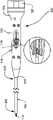
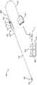
図2A乃至図2Cを参照すると、本開示による電気手術装置100が示されている。一般的に、装置100は、基端部103及び先端部105を有する筐体102と、開いた先端部106及び筐体102の先端部105に接続された基端部108を有するチューブ104とを有している。筐体102は、右側筐体110及び左側筐体112を含み、更にボタン114及びスライダ116のための設備を含んでいる。スライダ116の操作によって、チューブ104の開いた先端部106においてブレード118が露出される。ボタン114の操作によって、電気手術エネルギをブレード118に印加し、特定の実施形態では、以下で詳細に説明されるように、フローチューブ122を通るガスの流れが得られる。 2A-2C, an
加えて、無線周波数(RF)エネルギ源を装置100に接続するために、筐体102の基端部103に変圧器120を設けることができる。装置100内に変圧器120を設けることにより(電気手術発電機に変圧器を配置するのではなく)、装置100用の電力は、変圧器が発電機に遠隔配置される場合に必要な電力よりも高い電圧と低い電流から作り出される。この結果、より低い熱化効果が得られる。対照的に、いくつかの実施形態では、発電機に戻る変圧器は、より低い電圧、より高い電流で印加電力を生成し、より大きな熱化効果をもたらす。したがって、装置100に変圧器120を設けることにより、手術部位の組織への付随的な損傷が最小限に抑えられる。 Additionally, a
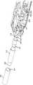
線A-Aに沿った装置102の断面図が図2Cに示されている。フローチューブ122は、筐体102及びチューブ104内に配置され、装置100の長手軸に沿って延設されている。フローチューブ122の先端部124において、ブレード118がフローチューブ122内に保持されている。フローチューブ122の基端部126は、チューブコネクタ128及び可撓性チューブ129を介してガス源に接続されている。フローチューブ122の基端部126は、変圧器120に接続されるプラグ130を介してRFエネルギ源にも接続される。フローチューブ122は、後述するようにプラズマ印加又は電気手術切断に使用される場合に、ブレード118にRFエネルギを伝達するように、導電性材料、好ましくはステンレス鋼を用いて形成されている。外管104は、非導電性材料、例えば、Lestran(商標)から構成されている。スライダ116は、保持カラー132を介してフローチューブ122に接続されている。プリント回路基板(PCB)134が筐体102内に配置され、ボタン114を介して変圧器120からのRFエネルギの印加を制御する。 A cross-sectional view of
スライダ116は、直線方向に自由に移動可能であってもよいし、装置100の操作者がブレード118を過度に延ばさないように、増分運動、例えばラチェット運動のための機構が組み込まれてもよい。ブレード118の増分移動のための機構を使用することにより、操作者は、露出したブレード118の長さを十分に制御し、手術部位の組織への損傷を回避することができる。 The
外管104の先端部106の拡大図も図2Cに示されている。ここで、ブレード118は、少なくとも1つのシール136によって外管104内の適所に保持されているフローチューブ122に連結されている。少なくとも1つのシール136は、チューブ104及び筐体102へのガスの逆流を防ぐ。円筒形セラミックインサート138は、外管104の先端部に配置され、装置100の長手軸に沿って刃を保持し、外管104の先端部を超えて刃が露出するときの機械的切断中に構造的支持を提供する。 An enlarged view of
ここで、装置100の動作態様を、図3A及び図3Bを参照して説明する。図3Aは、装置の拡大断面図を示し、図3Bは、装置の正面図を示している。 The mode of operation of
図3Aを参照して、フローチューブ122は、フローチューブ122の周りに配置された円筒状絶縁体140とともに外管104内に配置されている。スライダ116は、絶縁体140に接続され、ブレード118を延出させたり引っ込めたりするために使用される。外管104の先端部106において、環状又はリング形状のシール136及び円筒形セラミックインサート138がフローチューブ122の周りに配置される。図3Bに示されるように、略平板状のブレード118は、ブレード118の両側に2つのガス通路142、144が形成されるように円筒状フローチューブ122の内周に接続されている。ガスが筐体の基端部103からフローチューブ122を通って流れると、ガスは、ブレード118を通過して外管104の先端部から出る。 Referring to FIG. 3A, flowtube 122 is positioned within
図3Aに示すようにブレードが後退位置にあるとき、装置102は、プラズマを生成するのに適している。後退位置では、RFエネルギは、フローチューブ122を介して電気手術発電機(図示せず)からブレード118の先端146に伝えられる。次いで、ヘリウム又はアルゴンなどの不活性ガスが、電気手術発電機又は外部ガス源のいずれかからフローチューブ122を通して供給される。不活性ガスが、高電圧及び高周波数に保持されたブレード118の鋭角の先端点146上を流れると、低温プラズマビームが生成される。
図4を参照して、ブレード118は、スライダ116を介して前進し、先端146は、外管104の先端部106を通過して延びる。この状態では、ブレード118は、2つの切断モード:機械的切断及び電気手術的切断に使用することができる。機械的切断モードでは、RF又は電気手術エネルギはフローチューブ122又はブレード118に印加されず、したがって、ブレード118は非通電状態にある。このモードでは、ブレード118を使用して、機械的切断により組織を切除することができる。組織が除去された後、ブレード118は、スライダ116を介して引き込まれ、電気手術エネルギ及びガスがボタン114を介して印加されて、手術患者部位の焼灼、滅菌及び/又は止血のための低温プラズマビームが生成される。 Referring to FIG. 4,
電気手術切断モードでは、電気的にエネルギを与えられ、不活性ガスの流れで包まれた状態で、ブレード118が前進して使用される。この構成は、電気手術エネルギが切断を行う電気手術ナイフのアプローチに似ている。ただし、不活性ガスの流れを追加すると、カットは実質的に焼痂を示さず、切断部位の側壁に沿った付随的な損傷はほとんど生じない。切断速度はかなり速く、ナイフの刃が電気的に通電されていないとき、つまり機械的切断モードに比べて、機械的切断抵抗が小さくなる。このプロセス中に止血も影響を受ける。 In the electrosurgical cutting mode,
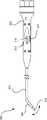
更なる実施形態では、本開示の電気手術装置は、関節運動する先端部を有している。図5を参照して、電気手術装置200は、上述の実施形態と同様の態様を有している。しかしながら、この実施形態では、先端部206、例えば、約2インチの部分は、手術部位で操縦できるように可撓性を有している。追加の制御部217、例えば、スライダやトリガなどが、基端筐体202に設けられて、先端部206の曲げを制御する。上述の実施形態と同様に、電気手術エネルギをブレード218に印加し、特定の実施形態では、フローチューブを通るガスの流れを可能にするボタン214が提供される。さらに、スライダ216に対する操作によって、開いた先端部206においてブレード218が露出される。 In a further embodiment, an electrosurgical device of the present disclosure has an articulating tip. Referring to FIG. 5, an
一実施形態では、関節運動制御部217は、2つのワイヤを含み、一方は、関節運動するように引っ張り、もう一方は先端部206を真っ直ぐにするように引っ張る。外管204は、図2に示される設計と同様である。外管204は、剛性であり、好ましくはUltem(商標)、Lestran(商標)又は同様の材料で作られ、最後の2インチまでは胃腸(GI)フレキシブルスコープの材料と同様の材料で作られる。特定の実施形態では、メッシュ注入テフロン(登録商標)又は類似の材料及び可撓性の絶縁材料を外管204の内側に配置することができ、先端部206が少なくとも45°曲がり、ガスを運ぶ内側チューブをつぶさないようにする。ブレード218は、曲げることはできるが、まっすぐな位置ではその形状を保持するニチノール(商標)などの柔軟な金属材料を用いて形成されている。あるいは、直線状の金属ブレード218は、連結された金属、例えばステンレス鋼、タングステンなどで作られた先端2インチに設けられている。金属ブレード218は、それでも電流は流れるが曲げることができ、ブレード218の切断部分は、連結部分の先端部に取り付けられる。 In one embodiment,
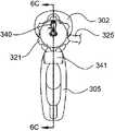
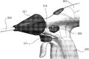
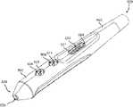
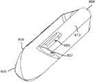
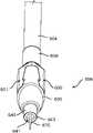
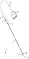
別の実施形態において、本開示の電気手術装置は、曲がった先端アプリケータを含んでいる。図6A乃至図6Cに示されるように、電気手術装置300は、トリガ型のハンドピース又は低温プラズマ用の曲がった先端アプリケータとして構成され、上記の実施形態と同様の態様を有する。しかし、この実施形態では、先端部306は、例えば特定の実施形態では約28.72mmにおいて予め曲げられており、手術部位18で先端部306を操作するために回転可能である。電気手術装置300は、操作者による装置の操作を容易にするためのハンドル305を備えた筐体302を有している。電気手術装置300は、筐体302の基端部303に配置された変圧器320、プラズマを生成するためにアプリケータ又はハンドピースを作動させるようにトリガ型ボタンとして構成された作動ボタン314、放電電極を備えた絶縁管304又はその中に配置されたブレード318を含んでいる。放電電極又はブレード318は、導電性の金属管322に接続されている。導電性の金属管322は、スライダアセンブリ319と総称されるスライダボタン316に更に接続される。スライダボタン316については、図7A乃至図7Dを参照して以下により詳細に説明する。スライダボタン316は、絶縁管304の先端部306を越えて放電電極又はブレード318を延出又は後退させる金属管322を移動させる。絶縁管304の基端部308にノブ321が設けられ、絶縁管304、ひいては、アプリケータの先端部306の360度の回転を可能にする。加えて、アプリケータを電気手術発電機に接続するためにコネクタ323が設けられる。特定の実施形態では、コネクタ323は、ケーブル325を介してアプリケータ又は装置300に供給される電気手術エネルギ及びガスを受け取る。 In another embodiment, an electrosurgical device of the present disclosure includes a curved tip applicator. As shown in FIGS. 6A-6C,
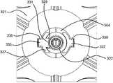
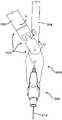
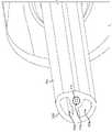
図7A乃至図7Dを参照して、スライダアセンブリ319をより詳細に説明する。図7Aは、スライダアセンブリ319の斜視図である。図7Bは、スライダアセンブリ319の正面図である。図7Cは、スライダアセンブリ319の断面図であり、図7Cは、スライダアセンブリ319の断面図である。図7Dは、スライダアセンブリ319の先端部306の内部構造を示している。セラミックインサート338が装置300の先端部306において使用され、装置がプラズマビーム生成モードで使用されるときに、潜在的な高温から外管先端筐体340を保護する。外管先端筐体340は、高温においてその機械的特性を保持する形状記憶ポリマ又は材料から形成される。例示的な形状記憶ポリマは、ポリエーテルエーテルケトン(PEEK)熱可塑性ポリマを含むが、他の形状記憶材料も本開示の範囲内にある。セラミックインサート338に隣接したわずかに大きい直径を有する外管先端筐体340は、先端アセンブリに機械的支持をもたらすのに十分に剛性であるが、先端が予め設定された様々な曲げ角度に対応するのに十分な可撓性を有している。電極又は手術用ブレード318は、外管筐体340内に収容され、スプリング344に接続されたアダプタ管342に取り付けられている。スプリング344の基端部346は、フローチューブ322に取り付けられている。アダプタ間の構成要素の接続、例えば、スプリング344とフローチューブ322(全体的に、符号341で示されている)との間、スプリング344とアダプタ管342(全体的に、符号343で示されている)との間及びアダプタ管342とブレード318(全体的に、符号345で示されている)との間の接続は、レーザ溶接を含むがこれに限定されない様々な方法によって達成され得る。 7A-7D,
代替的に可撓性のチューブ又は被覆として構成され得る熱収縮管348は、スプリング344の周囲に配置され、スプリング344をしっかりと覆う。熱収縮管348、可撓性のチューブ又は被覆は、ガスシールを提供し、また、スプリング344をフローチューブ322に対してシールする。すなわち、熱収縮管348は、スプリング344とフローチューブ322との接合部に設けられ、フローチューブ322の少なくとも一部に亘って延設されている。スプリング/熱収縮管の一体化構造は、アプリケータの先端がトロカールの先端部から出てきたときに、約15°から30°の曲げを可能にするのに十分な可撓性を有している。スプリング344を覆っている熱収縮管348は、フローチューブ322と同様の特性を有している。これにより、ガスが、例えば、フローチューブ322及び熱収縮管348から漏れることなく、ブレード318を通り抜けることができるとともに15度から30度の範囲の曲げを先端に施与することができる。熱収縮管348、被覆管又は被覆は、絶縁性及びガス不透過性である様々な材料から作られてもよいが、コイル巻き間の間隔を密閉し、様々な角度の曲げを可能にするスプリング344に適合するのに十分な可撓性を有している。更に、曲げられた先端の他の鋭角が本開示の範囲内であると考えられる。 A
フローチューブ322、スプリング344及びアダプタ管342はすべて、不活性ガス及び電気エネルギの両方が手術用ブレード318に流れることを可能にする。オプションとしてOリングスペーサ352によって適所に保持されたOリング350は、ガスシールに影響を及ぼし、筐体302又はハンドピースへの不活性ガスの漏れを防ぐ。例えば、Lestran(商標)又は他の適切な非導電性材料から形成された外管筐体304は、アセンブリ全体の機械的支持と電気的に安全性を有する絶縁の両方を提供する。
保持スリーブ又は滑り止めリング337がチューブ304に配置されている。滑り止めリング337は、ノブ321と係合して、チューブ304及び先端部306への回転に衝撃を与えるが、その詳細については、図8C、図8D及び図8Eに関連して以下で説明する。上部スライダ筐体356及び下部スライダ筐体358を有しているスライダ筐体354は、フローチューブ322に連結されている。スライダ筐体354は、筐体302の外面でアクセス可能なスライダボタン316に接続された翼部材360、361を更に含んでいる。バリアスリーブ355は、フローチューブ322の周りに配置されたスプリング357を保持するために、スライダ筐体354に接続されている。使用中、スライダボタン316を先端にスライドさせると、フローチューブ322がアプリケータの先端部306に向かって移動し、電極318を外管先端筐体340の先端を越えて延出させる。電極318を引っ込めるために、スプリング357がスライダ筐体354をアプリケータ又はチューブ304の基端部308に向かって駆動する解放ボタン359が操作される。 A retaining sleeve or
電気接点363、例えば、銅接点は、フローチューブ322の基端部の周りに配置され、電気手術エネルギを電極318に提供するための電気手術エネルギ源に接続されている。ガスフローカプラー365は、フローチューブの基端部に配置されケーブル325に接続されている。ケーブル325は、フローチューブ322へのガスの供給に用いられる。
図8Aは、筐体又はハンドピース302に取り付けられたアプリケータを例示しており、アプリケータの先端部306を約360度回転させることもできる。ハンドピース302上の回転ノブ321は、先端部306及び支持管アセンブリの曲げられた先端全体の回転を可能にする。ハンドピース302は、様々なレバーや押しボタンを収容している。これらのレバーや押しボタンは、手術用ブレード又は電極を延出させるために用いられたり(例えば、スライダボタン316を介して)、電気エネルギの印加やガス流の供給の開始に用いられたり(例えば、トリガ314を介して)、ブレード又は電極を引き込んだり(例えば、リリースボタン359を介して)、予め設定された電力レベルやガス流量などの他の使用者定義機能を実現するために用いられたりする。 FIG. 8A illustrates the applicator attached to a housing or
図8B乃至図8Eを参照して、ノブ321の操作について説明する。ノブ321は、基端部323及び先端部325を含む略円錐台形状を有している。基端部323は、例えば、実矧ぎ構造を用いてスライダボタン316に接続されている。実矧ぎ構造により、スライダボタン316を中心としたノブ321の回転が可能になる。滑り止めリング327(保持スリーブとしても知られる)は、溝329及びタブ331を介して外管304に固定的に接続されている。ノブ321の先端部325は、外管304の回転を可能にするために滑り止めリング327と接触している。ノブ321が回転すると、リング327の外面上の少なくとも1つのリブ又は突起333がノブ321の内面に形成された溝335に引っ掛かり、回転を可能にする。 Operation of the
ノブ321が回転すると、滑り止めリング327が回転する。この結果、外管304が回転する一方で、内側のフローチューブ322は回転方向に対して固定されている。外管304は、外管の先端筐体340に固定的に接続されている。外管先端筐体340が回転しているとき、スプリング344及びブレード318は外管先端筐体340内で浮いた状態にあり、先端部306の回転を可能にする。すなわち、スプリング344及びブレード318は回転せず、ブレード318は、外管先端筐体340の回転の間、同じ平面に留まる。すなわち、ブレードの平面は、筐体302のハンドル305の平面に平行のままである。例えば、ブレード318が垂直である場合、ブレード318は、外管304/外管先端筐体340が如何なる回転角度であっても垂直のままである。 As the
スライダボタン316及びノブ321は、装置の長手方向軸に沿って一緒に動き、ブレード318を延出させたり引っ込めたりする。スライダボタン316が矢印dで示される方向に作動すると、ノブ321は、同じ方向にリング327上をスライドして移動する。スライダボタン316は、外管304が同じ位置にある間に内側のフローチューブ322を移動させる。外管304は回転運動するけれども、長手方向軸の方向には運動しない。さらに、内側のフローチューブ322は、長手方向軸の方向に移動するけれども、回転はしない。電極318を後退させるために、解放機構367が解放ボタン359を介して作動され、スプリング357がスライダ筐体354を介して内側のフローチューブ322をアプリケータの基端部308に向かって移動できるようにする。
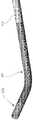
図9Aは、本開示による内側の導電チューブ422の別の実施形態を示している。内側の導電チューブ422は、チューブ422の先端部403が上述の電気手術装置の先端部306の回転を可能にするのに十分な可撓性を有することを可能にする複数のカット401、例えば、レーザカットを有している。図9Bを参照すると、図9Aに示される内側の導電チューブ422を使用する電気手術装置の先端部の断面図が示されている。チューブ422の先端部403は、ブレード318に固定的に接続されている。チューブ422を使用する電気手術装置の動作は、図7乃至図8Cに示す実施形態に関して説明したものと同様である。 FIG. 9A shows another embodiment of an inner
図10A乃至図10Cは、本開示による装置300などの電気手術装置の動作を示している。図10Aは、トロカールへの挿入前の電気手術装置の先端部を図示している。図10Bは、トロカールを通過する電気手術装置の先端部を示している。図10Cは、完全に挿入されたときにトロカールの先端部から現れるアプリケータの先端部を示している。 10A-10C illustrate the operation of an electrosurgical device such as
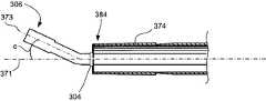
図10Aは、低温プラズマアプリケータの通常の状態又は力を受けていない状態を示している。図10Aでは、低温プラズマアプリケータの先端部306は、所定の角度a、例えば、約0度から約20度でチューブ304に対して予め曲げられているが、他の角度も本開示の範囲内である。図10Aでは、先端部306の長手方向軸373は、チューブ304の長手方向軸371に対して鋭角、例えば、角度aで予め曲げられている。予め曲げられた角度は、先端部306の通常の位置又は応力を受けていない位置である。先端部306は、外管304に対する先端部306が所定の角度aよりも小さい角度になるように操作又は応力を加えることができるため、アプリケータはトロカールを通過することができる。 FIG. 10A shows the normal or unforced state of the cold plasma applicator. In FIG. 10A, the cold
図10Bは、例示的なカニューレ又はトロカール370を示している。カニューレ又はトロカール370は、中心軸375に沿って整列した管状部材374に接続されたハブ372を有している。特定の実施形態では、ハブ372は、弁及びガス入力構成要素を収容するためのポート376と、手術部位を洗浄するために必要な又は所望の流体を導入するための流体入力部378とを有していてもよい。ハブ372は、管状部材374に挿入される低温プラズマアプリケータ300を受け入れるための開口部380を有している。管状部材374は、基端部382及び先端部384を有している。図10Bに示されるように、低温プラズマアプリケータ300の先端部306は、角度bでチューブ304に対してまっすぐにされ、角度bは角度aよりも小さい。角度bは、先端部306の長手方向軸373とチューブ304の長手方向軸371との間の角度として測定される。先端部306が角度b、すなわち、力が加わった状態又はストレス状態の下で、低温プラズマアプリケータ300をトロカール370の開口部380に挿入し、先端部306及びチューブ304をトロカール370の管状部材374に嵌める。先端部306の長手方向軸373が角度bである場合、外管先端筐体340は、外管304と実質的に同軸(又は直線)である。 FIG. 10B shows an exemplary cannula or
図10Cに示すように、低温プラズマアプリケータ300の先端部306がトロカールの先端部384の開口部を通過した後、先端部306はその挿入前の状態、すなわち無応力状態に戻ろうとする。先端部306は、挿入前の角度aよりもわずかに小さい角度cまで移動する。角度cは、先端部306の長手軸373とチューブ304の長手軸371との間の角度として測定される。角度cは角度aよりも小さいが、角度bよりも大きい、すなわち、a>c>bである。先端部306がトロカールの先端部384の開口部を通過すると、使用者又は外科医は、曲げられた先端部を、ノブ321を介して外部回転させて、標的組織により正確に向けることができる。 As shown in FIG. 10C, after the
外管先端筐体340の形状記憶特性により、アプリケータの先端部306を特定の処置に最も適した所定の角度に予め曲げ、所定の角度よりも小さい角度に真っ直ぐにすることができる。アプリケータをトロカールなどに挿入し、手術部位にあるときに実質的に所定の角度に戻すことを可能にする。本開示の様々な実施形態により、電気手術装置は、複雑且つ難解な操作機構を必要とすることなく、絶縁外管の長手軸に対してプラズマビームを向け直すことができる。 The shape memory properties of the outer
さらに、装置300をトロカール370内に引き込むことにより、先端部306の小さな部分がトロカール370の先端部を超えて少しだけ延出する(例えば、約1乃至5mm)。外側チップ筐体340は、外管筐体304と実質的に同軸になる。装置は、例えば、まっすぐ構成において、すなわち、実質的にトロカールの中心軸の方向で、プラズマを生成するために使用され得る。 Additionally, withdrawing the
図11Aを参照すると、本開示の実施形態による電気手術装置500が示されている。 Referring to FIG. 11A, an
図11Aに示されるように、電気手術装置500は、先端チップアセンブリ506、剛性シャフト503、可撓性の絶縁外管504、筐体502、ケーブル525及びコネクタ523を有している。筐体502は、ケーブル525を介してコネクタ523に接続されている。さらに、筐体502は、剛性シャフト503及び外管504を介して先端チップアセンブリ506に接続されている。一実施形態では、外管504は、可撓性であり、チップ506を回転又は移動させて広範囲の位置に到達させることができる。チップ506は、把持ツール(例えば、鉗子)を使用してチップ506を把持して、チップ506の向きを制御できるように構成される。例えば、図11Bを参照して、鉗子900に連結された装置500が示されている。図11Bに示されるように、鉗子900は、制御インターフェース904、シャフト902及び顎部又は把持部材906を含む。以下により詳細に説明するように、チップ506は、鉗子900の顎部906によって把持されて、必要に応じてチップ506の向きを制御するように構成される。 As shown in FIG. 11A,
図11Aを再度参照して、装置500は、ESU12などのESUに接続されて、そこから電気手術エネルギ及び/又はガスを受け取ることができる。一実施形態では、筐体502は、限定ではないがボタン512及び514などの複数のボタンと、限定ではないがスライダ516などの1つ又は複数のスライダとを含むことができる。この実施形態では、スライダ516は、電極518がチップ506のチャネルに配置されている場合、チップ506に対する電極518の前進及び後退を制御するように構成される(以下により詳細に説明する)。いくつかの実施形態では、電極518は、ブレードとして構成され、他の実施形態では、電極518は針として構成される。一実施形態において、ボタン512及び514は、装置500の動作モードを制御するように構成されてもよい。動作モードには、チップ506の開口から放出されるプラズマビームの特性が含まれる。例えば、ボタン512は、Jプラズマ又は低温プラズマモードを制御するように構成されてもよく、ボタン514は、ガスあり又はガスなしで単極凝固モードを制御するように構成されてもよい。 Referring again to FIG. 11A,
別の実施形態では、装置500は、装置500の異なる動作モードを制御するためのフットスイッチインターフェース850を含んでいてもよい。フットスイッチインターフェース850は、1つ又は複数のフットスイッチ852、854を含み、ESU12に接続されている。1つ又は複数のフットスイッチ852、854の押し下げに応答して、通信信号がフットスイッチインターフェース850を介してESU12に送信され、ESU12を介して装置500に提供される電気手術エネルギを制御する。このようにして、フットスイッチインターフェース850は、処置中に装置500が動作する動作モード(例えば、低温プラズマ、凝固、切除など)を制御するように構成されている。2つのフットスイッチ852、854が示されているが、いくつかの実施形態では、フットスイッチインターフェース850は、装置500の動作のモードごとに別個のフットスイッチを含んでいてもよい。他の実施形態では、追加のフットスイッチをフットスイッチインターフェース850に含めて、ESU12によって装置500に提供される電力及び/又はガス供給装置(例えば、ESU12を含む)によって装置500に提供されるガスを制御することができる。 In another embodiment,
図12A及び図12Bを参照すると、本開示による筐体502の斜視図が示されている。図12A及び図12Bに示されるように、筐体502は、先端部528及び基端部529を有している。先端部528は、チャネル526を含み、チャネル526は、剛性シャフト503の一部を収容するように構成されている。基端部529は、チャネル527を含み、チャネル527は、チューブ又は回転スリーブ530(図12Eに示される)の一部を収容するように構成されている。筐体502は、また、ボタンキャビティ505及び509及びスライダスロット522を含み、キャビティ505、509及びスロット522は、筐体502の外面501上に形成されている。ボタンキャビティ505は、ボタン512を収容するように構成され、ボタンキャビティ509は、ボタン514を収容するように構成されている。さらに、スライダスロット522は、スライダ516を収容するように構成されている。 12A and 12B, perspective views of
図12C及び図12Dを参照すると、本開示によるボタン512、514及びスライダ516の斜視図が示されている。図12C及び12Dでは、ボタン512は突起513を含み、ボタン514は突起515を含む。ボタン512がボタンキャビティ505に配置されると、突起513はキャビティ505の開口部507に挿入されるように構成されている。また、ボタン514がボタンキャビティ509に配置されると、突起515はキャビティ509の開口部511に挿入されるように構成されている。以下により詳細に説明するように、ボタン512又は514が押されると、ボタン512、514の突起513、515は、筐体502の内部に配置されたプリント回路基板558(図13Aに示す)と接触する。 12C and 12D, perspective views of
図12C及び12Dを参照すると、スライダ516は、第1部分536、第2部分517及び第3部分520を有している。スライダ516は、筐体502に接続され、スライダ516の第1部分536は、筐体502の外面501上又はその直上に配置され、スライダ516の第2部分517は、筐体502のスロット522を通して配置される。スライダ520の第3部分は、筐体502の内部に配置されている。スライダ516の部分520は、雌部材537及び雄部材538を有している。チャネル519は、雌部材537から雄部材538まで延設されている。以下でより詳細に説明するように、スライダ516は、使用者が部分516を介してスロット522に沿って先端又は基端にスライダ516をスライドさせて、ブレード518又は他の適切な形状の電極(例えば、針電極)を延出させたり引っ込めたりするように構成される。例えば、スライダ516がスロット522の先端部521に向かって前進すると、ブレード518はチップ506の先端部を越えて延び、スライダ516がスロット522の基端部524に向かって引っ張られると、ブレード518はチップ506のチャネル(以下で詳述される)に引き込まれる。 12C and 12D,
スライダ516の部分520はまた、雄部材801及びチャネル662を有している。雄部材801はチャネル803を有している。以下により詳細に説明するように、チャネル803は、電線又はケーブルの一部を収容するように構成され、チャネル662はダボを収容するように構成されている。一実施形態では、チャネル803は、スライダ516の部分520内のチャネル519と合流して、電線又はケーブルの部分を導電性のガスフローチューブに接続できるようにしている。
上述のように、筐体502のチャネル527は、回転スリーブ530を収容した状態で保持するように構成されている。図12E及び図112Fを参照すると、本開示によるスリーブ530の斜視図が示されている。図12E及び図12Fを参照すると、一実施形態では、スリーブ530は、略円筒形に構成される。スリーブ530は、スリーブ530の先端部532からスリーブ530の基端部533まで延設された内部チャネル531を有している。さらに、スリーブ530は、スリーブ530の外面に形成されたスロット534を有している。一実施形態では、スロット534は半円として構成される(すなわち、スロット534は、スリーブ530の外側円筒面の周面に形成されているけれども、完全な円を形成していない)。 As noted above,
スロット534は、チャネル527に配置されたタブを受け入れるように構成されている。例えば、図12Gを参照すると、本開示による筐体502の基端部529の部分斜視図が示されている。図12Gに示されるように、チャネル527は、筐体502の内面552に配置された半円形タブ551を有している。スリーブ530がチャネル527に配置されると、タブ551はスロット534に配置される。したがって、スリーブ530は、チャネル527に回転可能に配置され、筐体502に接続されている。
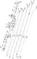
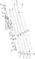
図13A及び図13Bは、本開示による装置500のいくつかの構成要素の分解斜視図を示している。図13A及び図13Bに示されるように、上記の構成要素に加えて、装置500は、継手540、可撓性チューブ548、Oリング802、接続要素697、プリント回路基板(PCB)558、ケーブル562、熱収縮要素698、熱収縮部804、560、566、576、806、600、電線692、可撓性且つ導電性のガスフローチューブ570及び可撓性のフローチューブ導管580を有している。図13A及び図13Bに示される装置500の構成要素は、以下に詳述される。 13A and 13B show exploded perspective views of some components of
図13C及び13Dを参照すると、筐体502の一部が除去された装置500の部分側面図が図13Cに示されている。図13Dには、本開示による筐体502の一部が除去された装置500の部分斜視図が示されている。図13Dに示されるように、ケーブル525の先端部553は、スリーブ530のチャネル531を通して配置される。ケーブル525の可撓性のガスチューブ556(図13Eに示される)は、継手540に接続される。 13C and 13D, a partial side view of
図13Eを参照すると、ケーブル525の先端部553の斜視図が、本開示に従って示されている。図13Eを参照すると、一実施形態では、ケーブル525は、可撓性のガスチューブ556を有している。ガスチューブ556は、チャネル554を有している。図示されていないが、一実施形態では、コネクタ523は、ガス供給源に接続されるように構成されている。コネクタ523は、ケーブル525のガスチューブ556を介してガス供給源から装置500にガスを供給する。ケーブル525は、複数の電線555も有している。電線555は、以下により詳細に説明するように、コネクタ523及び装置500の他のいくつかの構成要素に接続されている。3本の電線555A、555B、555Cが示されているが、ケーブル525は必要に応じて任意の数の電線を含むことができる。コネクタ523は、ESU12などの電気手術発電機に更に接続されて、電線555を介して装置500に電力を提供することができる。一実施形態では、ガス供給源は電気手術発電機に含まれてもよい。 13E, a perspective view of
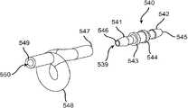
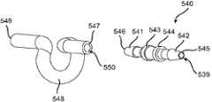
ガスチューブ556の先端部557は、継手540に接続されている。継手540はまた、可撓性且つコイル状のガスフローチューブ548に接続されている。図13F及び図13Gを参照すると、本開示による継手540及びチューブ548の斜視図が示されている。図13F及び図13Gに示されるように、継手540は、継手540の先端部546に配置された先端雄部材541と、継手540の基端部545に配置された基端雄部材542とを有している。継手540は、継手540の基端部545から継手540の先端部546まで延設されたチャネル539を有している。さらに、継手540は、タブ543及び544を有している。チューブ548は、基端部547と、先端部549と、基端部547から先端部549まで延設されたチャネル550とを有している。 A
継手540の基端雄部材542は、チューブ556のチャネル554の先端部557に配置されるように、基端雄部材542がチューブ556の先端部557に接続されている。基端雄部材542がチューブ556に接続されると、チューブ556の先端部557は、継手540のタブストッパー544に接触し、チューブ556がタブストッパー544を越えて前進するのを防ぐ。基端雄部材542は、略円錐形であり、チューブ556に挿入された後、基端雄部材542がチューブ556のチャネル554から容易に取り外されるのを防いでいる。 Proximal
フィッティング540の先端雄部材541は、チューブ548の基端部547に連結されている。先端雄部材541は、チューブ548のチャネル550の基端部547に配置されている。先端雄部材541がチューブ548に接続されると、チューブ548の基端部547が継手540のタブストッパー543に接触し、チューブ556がタブストッパー543を越えて前進するのを防ぐ。先端雄部材541は、略円錐形であり、チューブ548に挿入された後、先端雄部材541がチューブ548のチャネル550から容易に取り外されるのを防いでいる。チューブ548の先端部549は、スライダ516の雄部材538(図12Dに最もよく表されている)に連結されている。この結果、雄部材538は、チューブ548のチャネル550の先端部549に配置される。雄部材538は、略円錐形であり、チューブ548に挿入された後にチューブ548のチャネル550から容易に取り外されるのを防いでいる。 A
スライダ516は、構成要素697及び698のそれぞれに更に接続される。図13Hを参照すると、本開示による構成要素697及び698及びダボ664の斜視図が示されている。構成要素697は、先端部809及び基端部810を有している。チャネル811は、構成要素697の端部809から端部810まで延設されている。構成要素697の基端部810は、構成要素697の基端部810がチャネル519を通って配置されるように、スライダ516の雌部材537に収容されている(図13D及び図13Iに最もよく表されている)。構成要素697はまた、構成要素697の円筒状外面559の周りに形成された凹状円形溝663を有している。ダボ664は、スライダ516のチャネル662に配置されるように構成されている。ダボ664の外面665の一部は、構成要素697をスライダ516のチャネル519内に回転可能に保持するために、構成要素697の溝663に収容されている(図13Iに最もよく表されている)。
構成要素698は、先端部812及び基端部813を有している。チャネル814は、構成要素698の端部812から端部813まで延設されている。基端部813は、スライダ516の雄部材801を収容する雌部材として構成される(図12Cに示される)。このようにして、構成要素698の基端部813は、スライダ516に接続されるように構成され、スライダ516の雄部材801上に配置されている(図13D及び図13Iに最もよく示されている)。構成要素698の端部813が雄部材801上に配置されると、チャネル814及び803が整列し、同軸になる。
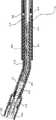
図13A及び図13Bを再度参照して、電線692、可撓性且つ導電性のガスフローチューブ570、可撓性の熱収縮部又は被覆576、可撓性のガスフローチューブ導管580及び可撓性の絶縁外管504が、本開示に従って示されている。電線692は、基端部693及び先端部694を有している。可撓性且つ導電性のガスフローチューブ570は、基端部571及び先端部572を有している。チューブ570の中空チャネル573は、チューブ570の端部571から端部572まで延設されている。図示されていないが、一実施形態では、可撓性且つ導電性のガスフローチューブ570は、チューブ570全体に配置された複数のレーザカット(上記のレーザカット401と同様)を有し、チューブ570は、導電性材料(限定されるものではないが、ステンレス鋼)で作られているけれども可撓性を有している。一実施形態では、チューブ570は304ステンレス鋼で作られている。別の実施形態では、チューブ570の少なくともいくつかは、チューブ570が可撓性であると同時に導電性であるように、複数の巻回部又はコイル(上述のスプリング348と同様)を含む導電性スプリングとして構成される。この実施形態では、漏れを最小限に抑えるために、スプリング,コイル又は巻回部がきつく巻かれている。 13A and 13B,
可撓性の熱収縮体576は、基端部577及び先端部578を有している。熱収縮体576の中空チャネル579は、熱収縮体576の端部577から端部578まで延設されている。可撓性のガスフローチューブ導管580は、基端部581及び先端部582を有している。ガスフローチューブ導管580の中空チャネル583は、端部581から端部582まで延設されている。可撓性の外管504は、基端部584及び先端部585を有している。可撓性の外管504の中空チャネル586は、可撓性の外管504の端部584から端部585まで延びる。以下でより詳細に説明されるように、電線692、チューブ570、熱収縮体576、及び導管580はそれぞれ、外管504のチャネル586を通して配置される。 A flexible heat shrink 576 has a
図13Iを参照すると、本開示による装置500のいくつかの構成要素の部分側面断面図が示されている。図13Iに示されるように、ガスフローチューブ570の基端部571の一部は、構成要素697のチャネル811及びスライダ516のチャネル519を通して配置される。構成要素697は、スライダ516の雌部材537のチャネル519に回転可能に配置されている。ガスフローチューブ570は、構成要素697に固定接続され、スライダ516がスロット522の端部521に向かって先端方向Aに前進するとき、ガスフローチューブ570も先端方向Aに前進する。同様に、スライダ516がスロット522の端部524に向かう方向Aとは反対の基端方向に後退する場合、ガスフローチューブ570もAとは反対方向の基端方向に後退する。さらに、構成要素697は、チャネル519内で回転可能であるので、ガスフローチューブ570も回転可能である。したがって、装置500の使用中に回転した場合にガスフローチューブ570の捻じれが防止される。以下により詳細に説明するように、ガスフローチューブ570の先端部572は、電気手術電極518に接続されている。電気手術電極518も、フローチューブ570の移動によって前進及び後退する。 Referring to FIG. 13I, a partial side cross-sectional view of some components of
一実施形態では、熱収縮管566及び576は、ガスフローチューブ570の上に配置されている。ガスフローチューブ570は、熱収縮体576に固定的に接続されている。この結果、可撓性のチューブ570の少なくとも一部が熱収縮体576のチャネル579に配置され、可撓性のチューブ570の外面が熱収縮体576の内面と接触する。また、一実施形態において、熱収縮体566及び576は重なり合う。この実施形態では、熱収縮体566は、熱収縮体576の少なくとも一部が中空内部に配置され、熱収縮体576の外面が熱収縮管566の内表面と接触するように、熱収縮体576に固定的に接続される。スライダ516が方向Aに前進又は方向Aとは反対の方向に後退すると、熱収縮部566、576及びガスフローチューブ570はそれぞれ一体的に延出又は後退する。 In one embodiment, heat shrink
ガスは、コネクタ523を介してケーブル525のチャネル554、継手540のチャネル539、コイル548のチャネル550及びスライダ516のチャネル519を介して提供される。ガスは、可撓性且つ導電性のガスフローチューブ570のチャネル573に流入する。上述のように、一実施形態では、可撓性且つ導電性のガスフローチューブ570は、チューブ570を可撓性にすることを可能にする複数のレーザカットを有している。別の実施形態において、可撓性且つ導電性のガスフローチューブ570は、複数のコイル又は巻きを有する可撓性且つ導電性のスプリングとして構成される。いずれの実施形態においても、レーザ切断、コイル又は巻きにより、可撓性且つ導電性のガスフローチューブ570のチャネル573に供給されるガスの一部がレーザ切断又はコイル/巻きを通って逃げることができる。熱収縮部566、576は、チューブ570のレーザカット又はコイル/ターンから漏れるガスを捕捉又は封じ込めるように構成されている。このようにして、チューブ570のレーザカット又はコイル/巻きから漏れるガスは、装置500の他の部分に逃げない。一実施形態では、熱収縮部566、576は、単一の熱収縮部として構成されてもよい。一実施形態において、Oリング802は、チューブ570の先端部571上に配置され、チャネル519へのガスの逆流を防止する。 Gas is provided through
図13Iに示されるように、1つ以上の電線を含むケーブル562は、構成要素698のチャネル814及びスライダ516のチャネル803を通して配置され、チューブ570の基端部571に接続されている。一実施形態では、ケーブル562は、スライダ516のチャネル519内のコレットにはんだ付けされたリードを介してチューブ570の基端部571に接続されている。コレットは、チューブ570に接続されている。 As shown in FIG. 13I, a
一実施形態において、熱収縮部804はケーブル562上に配置されている。更に、ケーブル562及び熱収縮部804は、熱収縮管560を通して配置されてもよい。 In one embodiment, heat shrink 804 is placed over
図13Jを参照して、ケーブル562は、PCB558に接続されている。PCB558は、ケーブル525の電線555A、555B、555Cにも接続されている。一実施形態では、電線555Aは、ボタン514に関連付けられたPCB558のソケットに接続されている。電線555Bは、ボタン512に関連付けられたPCB558のソケットに接続されている。電線555Cは、ケーブル562に接続されている。電線555Cは、電源(例えば、ESU12)を介して電気手術エネルギを受け取り、受け取った電気手術エネルギをケーブル562に提供するように構成されている。電気手術エネルギは、更にチューブ570に提供される。電線555A及び555Bは、それぞれボタン514、512に関連する信号を送信するように構成されている。ボタン512又はボタン514のいずれかが押されると、突起513及び/又は515がPCB558と接触する。突起513及び/又は515がPCB558と接触すると、ケーブル525及びコネクタ523を介して電気手術装置500に接続された電源に、電線555A及び555Bを介して通信信号が提供される。電源は、電線555A及び555Bを介して提供される通信信号に応答して、電線555C及びケーブル652を介してチューブ570に電気手術エネルギを提供するように構成されている。ボタン512、514はそれぞれ、装置500の異なる手術モードに対応している。一実施形態では、ボタン512は、Jプラズマ又は低温プラズマ活性化を制御するように構成されている。ボタン514は、装置500の単極凝固を制御するように構成される。 Referring to FIG. 13J,
別の実施形態では、ボタン512及び514並びに電線555A及び555Bは、装置500から取り外されている。1つ又は複数のフットペダル又はスイッチ852、854が、チューブ570に提供される電気手術エネルギを制御し、ボタン512及び514の機能を実行するように構成される。上述のように、フットスイッチ852、854は、ESU12などの電源又はESUに接続されてもよい。フットスイッチ852、854のいずれかが使用者によって押されると、通信信号がフットスイッチ852、854からESU12に送信される。ESU12は、波形を修正し及び/又は装置500の所望の動作モード(例えば、凝固、高周波療法、切除など)に基づいて必要に応じて電極518に提供される電気手術エネルギの特性を変更する。 In another embodiment,
図13Iを再度参照して、チューブ570及び熱収縮体576は、剛性シャフト503のチャネル569及びガスフローチューブ導管580のチャネル583を通じて配置される。図13C及び図13Dに示されるように、剛性シャフト503は、筐体502の先端部528に連結されている。剛性シャフト503の基端部567は、筐体502のチャネル526に配置されている。図13Kを参照すると、本開示による剛性シャフト503及び筐体502の一部の斜視図が示されている。図13Kに示されるように、チャネル526は、タブ593及び594を有している。タブ593及び594は、チャネル526の内面592上に配置され、そこから突出している。さら更に、シャフト503は、剛性シャフト503の円筒状の外周に形成された円形スロット590及び591を有している。チャネル526は、開口部595を有している。シャフト503の基端部567がチャネル526に配置される場合、タブ593及び594は、それぞれスロット590及び591に配置されるように構成されている。タブ593及び594並びにスロット590及び591は、チャネル526に剛性シャフト503を回転可能に保持するように構成される。剛性シャフト503の基端部567が筐体502のチャネル526に配置されると、チャネル569の基端部567は、筐体502のチャネル526の開口595と整列する。図13Lを参照すると、本開示による筐体502の断面斜視図が示されており、開口部595を見ることができる。熱収縮体576及びチューブ570は、開口部595を通して配置されている。 Referring again to FIG. 13I,
図13Kに示されるように、一実施形態では、装置500は、熱収縮部806を有している。熱収縮部806は、チャネル807を有している。筐体502から突出した剛性シャフト503の一部は、熱収縮部806のチャネル807を通して配置されるように構成されている。熱収縮部806は、図13D及び図13Lの剛性シャフト503に亘って配置されるのが最もよく見られる。 As shown in FIG. 13K, in one embodiment,
ガスフローチューブ導管580、熱収縮体576及びガスフローチューブ570は、外管504のチャネル586を通して配置される。例えば、図13Mを参照すると、本開示による装置500の別の部分側面断面図が示されている。図13Mに示されるように、剛性シャフト503の先端部568は、外管504の基端部584に接続されている。ガスフローチューブ導管580は、剛性シャフト503及び導管580それぞれのチャネル569及び586(図13Aに示される)の内面に固定的に接続されている。ガスフローチューブ導管580は、テフロンなどであるがこれに限定されない絶縁材料でできている。一実施形態では、導管580の内壁は、導管580及び外管504内のチューブ570及び熱収縮体576の滑りを助ける潤滑材料又はコーティングで構成されている。上述のように、外管504の先端部585は、チップ506に接続されている。以下により詳細に説明するように、ガスフローチューブ導管580、熱収縮体576及びチューブ570はそれぞれ、外管504のチャネル586を通ってチップ506の内部まで延出している。 Gas
さらに、可撓性の電線692(図13Aに示す)は、電線692の先端部694がチップ506に接続され、電線692の基端部693が筐体502の内部に接続されるように、外管504のチャネル586を通って延出されている。図13I及び図13Mに示されるように、一実施形態では、電線692は、導管580とシャフト503との間及び導管580と外管504との間に固定して配置される。図13C、図13D及び図13Kを参照して、筐体502の内部は、筐体502の内壁から延びる延長部材696を有している。延長部材696は、電線692の基端部693を収容するように構成されたスロット699を有している。一実施形態では、固定部材695(例えば、口輪)が電線692の基端部693に配置されて、延長部材696のスロット699に電線692を保持している。以下により詳細に説明されるように、電線692は、手術中の切断にブレード518が使用される場合、チップ506に構造的な一体性をもたらすように構成される。さらに、電線692は、チップ506が筐体502から引き離されたときに外管504が延出ことを防ぐように構成される。 In addition, flexible wires 692 (shown in FIG. 13A) are externally connected such that distal ends 694 of
図13Mを再度参照して、チューブ570及び熱収縮体576は、導管580のチャネル583内で摺動可能に構成されている。図13Mに示されるように、熱収縮体576はチューブ570に固定的に接続されて配置されている。チューブ504は、ガスフローチューブ導管580に固定的に接続されて配置されているけれども、ガスフローチューブ導管580は、熱収縮体576に固定的には接続されていない。このようにして、熱収縮体576及びガスチューブ570が、外管504及びガスフローチューブ導管580内で方向A(図13Mに示す)に延出するか又は方向Aとは反対の方向に後退する。外管504及びチューブ導管580は、チューブ570及び熱収縮体576に対して静止したままである。 Referring again to FIG. 13M,
上述のように、外管504、ガスフローチューブ導管580、熱収縮体576及びチューブ570は、それぞれ可撓性を有するように構成される。このようにして、装置500のチップ506を操作して(例えば、鉗子900などの装置を使用して)、筐体502に関して多種多様な位置に配置することができる。以下に、チップ506についてより詳細に説明する。 As discussed above,
図14A及び14Bを参照すると、本開示による先端チップアセンブリ506及び外管504の先端部、電線692、ガスフローチューブ導管580、熱収縮体576及びチューブ570の分解斜視図が示されている。図14A及び図14Bでは、チップ506は、電極又はブレード518、円筒形セラミックチップ640、外側チップ筐体606、環状Oリング形状のシール604、内側チップ筐体630、口輪又は固定部材635及び熱収縮部600を有している。セラミックチップ640は、セラミックチップ640の先端部643から基端部642まで延設されたチャネル641を有している。Oリング604は、開口部605を有している。外側チップ筐体606は、外側チップ筐体606の先端部609から基端部608に向かって延設されたチャネル607を有している。内側チップ筐体630は、内側チップ筐体630の先端部632から内側チップ筐体630の基端部633まで延設されたチャネル631を有している。内側チップ筐体630は、内側チップ筐体630の外面に配置された開口部634及び延長部材691を更に有している。延長部材691は、スロット636を有している。スロット636は、固定部材635を受け入れるように構成されている。熱収縮部600はチャネル690を有している。 14A and 14B, there are shown exploded perspective views of the
一実施形態では、外側チップ筐体606及び内側チップ筐体630が単一の構成要素として構成されている。 In one embodiment,
セラミックチップ640の基端部642は、外側チップ筐体606のチャネル607に配置されている。外側チップ筐体606及び内側チップ筐体630は、延長部材691が外側チップ筐体606のスロットによって収容され、チャネル607及び631が整列するように接続されるように構成される。例えば、図14Cを参照すると、本開示による外側チップ筐体606の斜視図が示されている。図14Cに示されるように、外側チップ筐体は、内面610に配置されたスロット659を有している。スロット659は、拡張部材691を収容するように構成されている。 A
図14Dを参照すると、本開示による装置500のチップ506の断面図が示されている。図14Dに示されるように、外管504は、内側チップ筐体630の基端部633に固定的に接続されている。ガスフローチューブ導管580の先端部582、電線692の先端部694、熱収縮体576の先端部578及びガスフローチューブ570の先端部572はそれぞれ、内側チップ筐体630のチャネル631及び外側チップ筐体606のチャネル607を通して配置されている。一実施形態において、熱収縮部600は、内側チップ筐体630の基端部633及び外管504の先端部585に亘って配置される。 Referring to FIG. 14D, a cross-sectional view of
電線692の先端部694は、開口部634を通じて内側チップ筐体630のスロット659内に配置され、固定部材635に接続されている。上述のように、電線692は、手術中にブレード518が切断に使用されるときにチップ506に構造的な一体性をもたらすために、チップ506及び筐体502のそれぞれに固定されるように構成されている。さらに、電線692は非弾性であるため、電線692は、チップ506から筐体502の最大距離を保証するように構成される。このようにして、外管504の過度の突出が防止される。 The
図14Dに示されるように、チューブ570及び熱収縮体576の先端部572及び578は、それぞれ、セラミックチップ640のチャネル641の基端部642を通して配置されている。ブレード518の基端部645は、セラミックチップ640のチャネル641の先端部643を通って配置され、可撓性且つ導電性のガスフローチューブ570の先端部572に固定的に接続されている。一実施形態では、可撓性且つ導電性のガスフローチューブ570の先端部572は、ブレード518の基端部645を受け入れるように構成された一対のスリット649、650(図14Aに最もよく示されている)を有している。 Distal ends 572 and 578 of
一実施形態では、セラミックチップ640のチャネル641の先端部643は、ブレード518を摺動可能に収容するように構成されている。たとえば、図14Eを参照すると、本開示によるチップ筐体606のチャネル607内に配置されたセラミックチップ640の斜視図が示されている。図14Eに示されるように、チャネル641の先端部643は、セラミックチップ640の内周に形成され、セラミックチップ640の先端部643からセラミックインサート640の基端部642に向かって延設され、直線方向に正反対の位置のスロット651、655を有している。スロット651は、ブレード518の延長部材657(図14A、図14B及び図14Dに示す)を収容するように構成されている。スロット655は、ブレードの延長部材656(図14A、図14B及び図14Dに示す)を収容するように構成され、ブレード518をスライド可能に保持している。図14F及び図14Gを参照して、ブレード518は、チャネル641のスロット651、655を通して配置され、延出位置で示されている。ブレード518がチャネル641のスロット651を通して配置されると、ガス通路652及び653がブレード518の各側に形成される。 In one embodiment, the
セラミックチップ640は、外側チップ筐体606に固定的に接続されている。このようにして、セラミックチップ640は、チップ筐体606(すなわち、先端チップ506)に対して回転可能ではない。さらに、延長部材656、657は、セラミックチップ640のスロット655、651に配置されるので、ブレード518は、セラミックチップ640及び先端チップ506に対して先端及び基端に摺動可能であるが、ブレード518は、セラミックチップ640及び先端チップ506に対して回転可能ではない。このようにして、ブレード518は、セラミックチップ640及び筐体506とともに回転する。 A
チャネル641、607、631は、熱収縮部572及び可撓性且つ導電性のガスフローチューブ570がチップ506のチャネル641、607、631内を自由に移動できるように構成されている。このようにして、スライダ516は、先端に前進又は基端に後退させられる。この結果、チップ506の先端部に対してブレード518は前進又は後退されるとともに、可撓性且つ導電性のガスフローチューブ570及び熱収縮体576は前進又は後退される。例えば、スライダ516がスロット522の端部521に向かって前進すると、ブレード518は、チャネル641の先端部643を越えて前進する。あるいは、スライダ516がスロット522の端部524に向かって引っ込められると、ブレード518は、セラミックチップ640のチャネル641の内部に引っ込められる。
一実施形態において、アルゴン又はヘリウムなどの不活性ガスが、ケーブル525及びコネクタ523を介して装置500に接続されたガス供給源から可撓性且つ導電性のガスフローチューブ570のチャネル573を介して提供されると、不活性ガスはチャネル641を流れ、ブレード518上の通路652及び653を通過する。ブレード518が後退位置にあるとき(図14D及び図14Eに示されるように)、装置500は、プラズマを生成するのに適している。後退位置では、RFエネルギ(ケーブル525及びコネクタ523を介して装置500に接続された電気手術発電機によって提供される)は、可撓性且つ導電性のガスフローチューブ570を介してブレード518の先端部644に伝えられる。不活性ガスが可撓性且つ導電性のガスフローチューブ570を介して供給され、通路562及び563を介してブレード518上を流れると、ブレード518は高電圧及び高周波に維持され、チップ506の先端部から放出される低温プラズマビームを生成する。 In one embodiment, an inert gas such as argon or helium is passed through
ブレード518が前進位置にある(すなわち、スライダ516がスロット522の端部521に向かって前進して、ブレード518をチャネル641の先端部643を越えて前進させる)とき、装置500は2つの切断モード:機械的切断及び電気手術的切断に使用される。機械的切断モードでは、RF又は電気手術エネルギは、可撓性且つ導電性のガスフローチューブ570又はブレード518に印加されない。したがって、ブレード518は非通電状態にある。このモードでは、ブレード518を使用して、機械的切断により組織を切除することができる。電気手術切断モードでは、電気的にエネルギを与えられ、不活性ガスの流れで包まれている間、ブレード518は前進し使用される。 When
図14A、図14B及び図14Dを参照して、Oリング又はガスシール604が、熱収縮体576の先端部578及びガスフローチューブ570の先端部572の周りに配置されている。図14Dに示されるように、シール604は、熱収縮体576及びチューブ570の周り並びにセラミックチップ640の基端部642と内側チップ筐体630のチャネル631の内面内に配置された球状タブ647との間に配置されている。シール604は、可撓性且つ導電性のガスフローチューブ570のチャネル573を介して導管580のチャネル583へブレード518に供給されるガスの逆流を防止するように構成されている。 14A, 14B and 14D, an O-ring or
上述のように、外管504、導管580、熱収縮体576及びチューブ570はそれぞれ、チップ506が装置500のハンドル502に対して複数の位置に到達できるように可撓性を有するように構成されている。一実施形態では、外側チップ筐体606は、鉗子900などの把持ツールによって把持されるように構成されている。例えば、図14A、図14B、図14E、図14F及び図14Gに示されるように、チップ筐体606は、一対の把持スロット660及び661を含む。把持スロット660及び661は、鉗子900の顎部906などの把持ツールの係合部材を収容するように構成されている。このようにして、把持スロット660及び661は、チップ506が把持ツールによって把持されることを可能にする。図11B及び図14Hを参照すると、本開示による鉗子900の顎部906がスロット660及び611を把持していることが示されている。把持具の顎部906又は鉗子900がチップ506のスロット660及び661を確実に把持すると、次に、鉗子900を使用して、使用者が望むように筐体502に対するチップ506の位置を操作することができる。 As described above,
鉗子900のシャフト902は、剛性の直線的なシャフトとして、又は代替的に様々な位置に操作されるように構成された複数のリンク部位として構成可能である。一実施形態ではシャフト902は、顎部906が装置500のチップ506を複数の方向(例えば、図14Hに示す回転方向B、C、及びD)に回転させるように構成される1つ以上の旋回又は回転部材908を有してもよい。一実施形態において、鉗子900は、制御インターフェース904を介して制御される。制御インターフェース904は、手動制御インターフェース(例えば、人間が鉗子900を手動で制御するための1つ以上の制御を含む)又はコンピュータ又はロボット制御インターフェース(例えば、鉗子900はコンピュータで操作される)。 The
例示的な実施形態では、先端505の向きを操作するために使用される把持ツールは、限定ではないが、IntuitiveSurgical(登録商標)製のda Vinci(登録商標)手術システムのProGrasp(商標)鉗子などのロボットアームであってもよいが、他のロボットアームであってもよい。システムはまた、チップ506を制御するために装置500とともに使用されてもよい。 In an exemplary embodiment, the grasping tool used to manipulate the orientation of
一実施形態では、装置500及び/又は鉗子900は、上述のトロカール370などのトロカールとともに使用できる。この実施形態では、第1トロカール又はカニューレ及び第2トロカール又はカニューレは、患者の体内の所望の組織部位へのアクセスを提供するために、それぞれ患者の体の一部を通して(例えば、患者の腹部を通して)配置され得る。先端チップ506及び外管504の少なくとも一部は、第1トロカールを通して配置されている。把持ツール又は鉗子900の一部(顎部906を含む)は、第2トロカールを通して配置されている。装置500の先端チップ506及び鉗子900の顎部906の両方は、組織部位へアクセス可能である。患者の体内で、先端チップ506のスロット660、661は、顎部906を収容している。鉗子900は、先端チップ506を制御し、手術的処置(例えば、機械的切断、電気手術的切断、切除、凝固、高周波処置、組織部位での低温プラズマビームなど)を実行する。別の実施形態では、先端チップ506及び外管504の少なくとも一部は、把持ツール又は鉗子900と同じトロカール又はカニューレに配置されてもよい。 In one embodiment,
別の実施形態では、装置500は開腹手術で使用されてもよい。 In another embodiment,
本開示の別の実施形態において、装置500の電極518は、平坦な電気手術用ブレードの代わりに電気手術用針として構成され得る。例えば、図15Aを参照すると、チップ506のセラミックチップ640を通して配置された電気手術針670を備えた装置500の部分斜視図が示されている。図15Bを参照すると、装置500の別の部分斜視図が示されており、電気手術針670がより詳細に示されている。図15Bに示すように、針670は、導電管又は保持部材680を介して可撓性且つ導電性のガスフローチューブ570の先端部572に固定的に接続されている。導電管680は、針670の周りに配置されている。図15Bに示される実施形態では、セラミックチップ640の先端部643は、スロット651、655又はガス通路652及び653を有していない。スライダ516がスロット522の端部521に向かって先端方向に前進すると、導電性のガスフローチューブ570も外管504及びガスフローチューブ導管580内で前進する。この結果、針670がチップ506の先端を越えて前進する。あるいは、スライダ516がスロット522の端部524に向かって基端方向に引っ込められると、導電性のガスフローチューブ570も引っ込められる。この結果、針670がチップ506の内部に引っ込む。さらに、導電性のガスフローチューブ570に印加されるRFエネルギは、導電性のチューブ608及び針670に伝えられる。この結果、上述のように手術部位にRFエネルギが印加される。 In another embodiment of the present disclosure,
本開示の別の実施形態において、装置500のボタン512及び514は除去され得る。例えば、図16Aを参照すると、本開示による装置700が示されている。装置700は、チップ706、シャフト又はチューブ704、筐体702、ケーブル725及びコネクタ723を有している。コネクタ723は、ケーブル725を介して筐体702に接続されている。さらに、シャフト704の先端部705は、チップ706に接続されている。シャフト704の基端部707は、筐体702に接続されている。スライダ716は、筐体702に配置されている。スライダ716は、スライダ516と同様に機能する。すなわち、スライダ716は、チップ706のチャネルに配置されている電極(例えば、電気手術ブレード又は針)の前進及び後退を制御する。一実施形態では、装置700は、電気手術発電機(図示せず)に接続されている。電気手術発電機は、1つ以上のフットペダル又はスイッチ(上述のフットスイッチ852、854など)に更に接続されている。1つ以上のフットペダル又はスイッチは、押されると、上述のボタン512及び514の機能を実行するように構成されている(例えば、チップ706に配置された電極に提供されるRFエネルギ及び/又はガスの特性を制御する)。コネクタ723は、ESU12などの電気手術発電機及び1つ以上のガス供給源(図示せず)に接続される。 In another embodiment of the present disclosure,
一実施形態では、シャフト704は、マルチルーメンシャフトとして構成されてもよい。マルチルーメンシャフト704は、装置500が有しているガスチューブ導管、熱収縮体及びガスフローチューブ580、576、570などを有していない。図16Bを参照すると、本開示によるマルチルーメンシャフト704の先端部705の斜視図が示されている。図16Bに示されるように、マルチルーメンシャフト704は、チャネル又はルーメン708、709及び710を含む。一実施形態では、マルチルーメンシャフト704は、チップ706が様々な位置に到達できるように、可撓性の絶縁材料又は非導電材料で作られている。 In one embodiment,
図16Cを参照すると、本開示による装置700の部分斜視図が示されている。図16Cでは、チップ706は、先端筐体729を有している。先端筐体729は、先端部739及び基端部738を有している。先端筐体729の基端部738は、マルチルーメンシャフト704の先端部705に連結されている。セラミックチップ740(セラミックチップ640に類似)は、チップ筐体729のチャネルの先端部739に配置されているとともに接続されている。チャネルは、チップ筐体729の先端部739からチップ筐体729の基端部738まで延設されている。図示されていないが、マルチルーメンシャフト704の先端部705は、先端筐体729内のチャネルの基端部738に配置されている。セラミックチップ740は、セラミックチップ740の先端部743からチップ筐体729内に配置されたセラミックチップ740の基端部まで延びるチャネル741を有している。電気手術用ブレード又は針718は、セラミックチップ740のチャネル741内に配置されている。一実施形態では、先端筐体729は、鉗子900などの把持ツールによって把持されるように構成された把持スロット760及び761も含み、チップ706を様々な位置に動かす(チップ706に関して上述したように)。 Referring to FIG. 16C, a partial perspective view of
図16Bを再度参照すると、一実施形態では、シャフト704のチャネル710は、可撓性の導電ロッド711を有している。可撓性の導電ロッド711の一端は、スライダ716に接続されている。可撓性の導電ロッド711の他端は、電気手術用ブレード又は針718に接続されている。スライダ516と同様に、スライダ716がシャフト704に向かって前進すると、ロッド711がチップ706に向かって前進するようにスライダ516は構成されている。これにより、電気手術用ブレード又は針718がセラミックチップ740のチャネル741の先端部743を越えて前進する。さらに、スライダ716がシャフト704から離れる方向に引っ込められると、ロッド711がチャネル711内に引っ込められるようにスライダ516は構成されている。この結果、電気手術用ブレード又は針718は、チャネル741内に引っ込む(図16Cに示すように)。 Referring again to FIG. 16B, in one embodiment,
図示されていないが、ロッド711は、筐体702内のケーブル725の1つ以上の電線に連結されている。電気手術エネルギがロッド711に印加されると、電気手術エネルギを電気手術ブレード又は針718に印加することができる。一実施形態では、ロッド711の基端部は、上述のようにチューブ570がケーブル562に接続されるのと同様の方法で、スライダ716を介してケーブル725の1つ以上の電線に接続されている。さらに、図示されていないが、ロッド711は、ロッド711が可撓性を有することを可能にする複数のレーザカットをロッド711全体に有している(レーザカット401と同様)。 Although not shown,
図示されていないが、一実施形態では、チャネル710は、ヘリウム又はアルゴンなどの不活性ガスがチャネル710を介してチャネル741に提供されるように、筐体702内のケーブル725に接続されている。 Although not shown, in one
別の実施形態では、ロッド711は、可撓性且つ導電性のガスフローチューブ570及び熱収縮体576などの可撓性且つ導電性のガスフローチューブ及び可撓性且つ導電性のガスフローチューブの周りに配置された熱収縮部で置き換えられてもよい。この実施形態では、可撓性の導電性のガスフローチューブ570及び熱収縮体576は、チャネル710内に摺動可能に配置されている。チューブ570及び熱収縮体576の先端部は、電気手術針又はブレード718に接続されている。熱収縮体576のチューブ570の基端部は、スライダ716に接続されている。この実施形態では、チューブ570は、ブレード518及びスライダ516に関して上述したのと同様の方法でブレード718及びスライダ716に接続されている。この実施形態では、スライダ716は、電気手術用ブレード又は針718の前進及び後退を制御する。さらに、チューブ570は、ガス及びRFエネルギがチップ706内の電気手術ブレード又は針に提供され得るように、筐体702内のケーブル725に接続されている。 In another embodiment,
図16Bを再度参照すると、別の実施形態では、チャネル708及び709のそれぞれは、ガス供給源に接続されて、チップ706にガスを提供し得る。例えば、一実施形態では、チャネル708及び709は、チャネル710と同じガス供給源に接続される。別の実施形態では、チャネル708及び709は、チャネル710に接続された不活性ガス供給源とは異なるガス供給源に接続されてもよい。たとえば、一実施形態では、チャネル708及び709は、酸素ガス供給源に接続されている。別の実施形態では、チャネル708、709及び710のそれぞれは、互いに異なるガス供給源に接続されてもよい。別の実施形態では、真空を1つ以上のチャネル708、709の基端部に接続して、手術部位を吸引したり、真空にしたりすることができる。一実施形態では、ケーブル725は、吸引したり、真空にしたりするために真空装置に接続された吸引チューブを含んでもよい。 Referring again to FIG. 16B, in another embodiment, each of
別の実施形態では、マルチルーメンシャフト704は3つ以上のチャネルを含んでもよい。例えば、図16Dを参照すると、マルチルーメンシャフト704の先端部705の正面図が示されている。マルチルーメンシャフト704は、第4チャネル714を有している。第4チャネル714は、チャネル708及び709と同じガス供給源又は異なるガス供給源に接続されてもよい。 In another embodiment,
上記の実施形態では、装置500、700の電極518、718は、先端チップ506、706に対して先端及び基端にスライド可能である。他の実施形態では、電極518、718は、先端チップ506、706に対して固定されるように構成されていてもよい。この実施形態では、可撓性の導電チューブ570及び可撓性の導電ロッド711は、外管504、704に対して移動不能又は固定されている。様々な実施形態では、電極518、718の位置は、様々な電気手術処置をサポートするために、完全に延出した、部分的に延出した又は完全に後退した位置に固定されてもよい。例えば、一実施形態では、電極518、718は、先端チップ506、706に対して後退位置又は実質的に後退位置に固定されている。この実施形態では、装置500、700はアブレーション用に構成されているが、機械的切断用には構成されていない。 In the above embodiments, the electrodes 518,718 of the devices 500,700 are slidable distally and proximally relative to the distal tip 506,706. In other embodiments, the electrodes 518,718 may be configured to be fixed relative to the distal tip 506,706. In this embodiment, the flexible
別の実施形態では、外管504及び/又は704は、剛性のまっすぐなシャフトとして構成されてもよい(すなわち、チューブ504、704は可撓性ではない)。導管580、チューブ570、及びロッド711も、チューブ504、704を有することなく、剛性且つまっすぐに構成されていてもよい。この実施形態では、装置500、700は、鉗子900などの把持ツールなしで使用するように構成されている。 In another embodiment,
図示及び説明されている様々な特徴は交換可能であり、すなわち、一実施形態に示されている特徴を別の実施形態に組み込むことができる。 The various features shown and described are interchangeable, ie, features shown in one embodiment can be incorporated into another embodiment.
たとえば、電極(例えば、ブレード、針など)のいずれかを延出又は後退させて、ESU12などのESUを介して装置100、200、300、500、700の電極に印加される高電圧及び高周波波形を修正することにより、様々な追加の電気手術用のプラズマビーム効果を達成できる。低温プラズマの生成に加えて、これらの効果には、Cool Coag(商標)効果としても知られる単極凝固及びガス支援凝固のいくつかの形態が含まれる。これらのガス支援凝固モードの1つでは、ヘリウムなどの不活性ガスが存在する間に凝固波形が電極に印加される。この結果、プラズマが形成される。この凝固モードでは、凝固を行うためにプラズマビームが標的組織に照射される。別の凝固モードでは、電気手術装置の電極に単極凝固波形を印加し、標的組織を電気手術装置と接触させることにより凝固が実行される。電極が標的組織に接触している間、ヘリウム又はアルゴンなどの不活性ガスが標的組織に供給されて、冷却効果を提供する(すなわち、標的組織の温度を下げる)。Cool Coag(商標)は、単極凝固波形のパワーとヘリウムなどの不活性ガスの冷却流を組み合わせるが、アルゴンなどの他のガスも使用可能である。このようにして、本開示による装置100、200、300、500、700などの単一の電気手術装置は、1)低温プラズマ放電、2)単極凝固効果、3)様々なガス支援放電又はプラズマを生成し得る。 For example, high voltage and high frequency waveforms applied to electrodes of
様々な実施形態において、装置100、200、300、500、700に接続されたESUに配置された2つの高電圧昇圧出力変圧器が、必要な波形を生成するために利用される。2つの高電圧昇圧出力変圧器の実施形態を含む例示的なシステムは、Rencher等に共有された米国特許第9,144,453号に開示されており、その内容は参照により本明細書に組み込まれる。1つの変圧器は、高電圧及び低電流用に最適化されており、上述の電気手術装置100、200、300、500、700それぞれのブレード118、218、318、518、718などのブレードが引き込まれた状態で低温プラズマビームを生成する際に利用される。もう1つの変圧器は、単極、双極、凝固などの電気手術処置に必要なやや低電圧で高電流に最適化されている。本明細書で説明する様々な動作モードに影響を与えるために、これらの変圧器の両方を、使用中の電気手術装置の発電機電源ユニット又はESUに配置することができる。電気手術装置500のボタン512、514などのハンドヘルドアプリケータ上のボタン又はフットスイッチ852、854などの適切なフットスイッチの選択は、必要とされている手順のためにどの変圧器を起動し、適切な波形を得るかを制御するように構成されている。 In various embodiments, two high voltage step-up output transformers located in the ESUs connected to the
単極凝固モード(たとえば、上記のように電気手術装置500のボタン514又は適切なフットスイッチ852、854を押すことにより作動する)では、凝固波形が電極に印加され、電気手術装置の電極と標的組織の間とを接触させることにより、凝固効果が標的組織に印加され得る。典型的な凝固波形のいくつかの例が図17Aに示されている。このモードでは、ヘリウムなどの不活性ガスが存在している間、不活性ガスはプラズマを生成しないけれども、標的組織に冷却効果をもたらす。 In a monopolar coagulation mode (eg, activated by pressing
プラズマ凝固モードでは(例えば、上述のように電気手術装置500のボタン514又は適切なフットスイッチ852、854を押すことにより作動する)、いくつかの形態のガス支援凝固(又はプラズマ凝固)は、標的組織から離れた電極の距離に影響される。これらの支援凝固は、ピンポイント凝固モード、穏やかな凝固モード、スプレー凝固モードを含んでいる。高い波高率又はピーク電圧とRMS電圧との比により、様々なガス支援凝固モードで流れる不活性ガスの点火が保証される。一実施形態では、プラズマ凝固中に使用される凝固モード(例えば、ボタン514又は適切なフットスイッチ852、854が押されたとき)は、電気手術エネルギを装置に提供している電気手術発電機又はESUで選択される。典型的な凝固波形のいくつかの例が図17Aに示されている。このようにして、発電機で凝固モードが選択された後(例えば、ピンポイント、穏やか又はスプレー凝固モード)、凝固ボタン(例えば、ボタン514)又は電気手術装置の適切なフットスイッチ852、854(例えば、装置500)が起動されると、選択された凝固モードが電気手術装置によって放出されたプラズマビームに採用される。 In plasma coagulation mode (eg, activated by pressing
ピンポイントで穏やかなガス支援凝固モードでは、プラズマ生成パルスグループ間に比較的短い期間が存在する。前の放電経路からの残留イオンは、後続の放電が同じ経路をたどることを保証し、低温プラズマビームと同じ指向精度を持つプラズマビームを提供する一方で、実質的に高い電流と向上された凝固能力を有している。 In the pinpoint and mild gas-assisted coagulation mode, there is a relatively short period between plasma-generating pulse groups. Residual ions from the previous discharge path ensure that subsequent discharges follow the same path, providing a plasma beam with the same pointing accuracy as a cold plasma beam, while providing substantially higher currents and improved coagulation. have the ability.
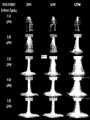
対照的に、ガス支援スプレーモードは、パルス間の期間がはるかに長く(例えば、図17Aに示される高周波モード波形を電極に印加することにより)、残留イオンの再接続を可能にする。したがって、優先的な残留放電経路はなく、個々の放電は、はるかに広い領域をランダムにカバーする。ガス支援スプレー凝固モード中に生成される放電の例を図18に示す。様々な電力設定及びガス流量に関して、電力設定は、上側のx軸に沿って示されている。ガス流量は、左側のy軸に沿って示されている。図示された放電は、約5.0mmのターゲット表面から一定の距離で発生している。 In contrast, the gas-assisted spray mode has a much longer period between pulses (eg, by applying the radio frequency mode waveform shown in FIG. 17A to the electrodes), allowing reconnection of residual ions. Therefore, there are no preferential residual discharge paths and individual discharges randomly cover a much larger area. An example of an electrical discharge produced during gas-assisted spray coagulation mode is shown in FIG. Power settings are shown along the upper x-axis for various power settings and gas flow rates. Gas flow rates are shown along the left y-axis. The illustrated discharge occurs at a constant distance from the target surface of approximately 5.0 mm.
図17Bは、電気手術装置の低温プラズマビームモード又はJプラズマモード中に使用される波形を示す。電気手術装置がJプラズマモードにあるとき(ボタン512、514及び/又はフットスイッチ852、854を介して選択されるように)、図17Bに示される波形は、Jプラズマモードである。ヘリウムなどの不活性ガスが電極の先端チップ上を流れると、図17Bに示される波形が電気手術装置の電極に印加され、低温プラズマ又はJプラズマが生成される。 FIG. 17B shows the waveforms used during the cold plasma beam mode or J-plasma mode of the electrosurgical device. When the electrosurgical device is in J-Plasma mode (as selected via
低温プラズマビームモードと同様に、様々なガス支援凝固モードでは、ビームの電力と不活性ガスの流量の比率を調整することにより、幅広い生理学的効果に影響を与えることができる。 As with cold plasma beam modes, various gas-assisted coagulation modes can affect a wide range of physiological effects by adjusting the ratio of beam power and inert gas flow rate.
上記から、本開示による単一の電気手術装置は、低温プラズマモード、単極凝固モード(電気手術装置の電極が標的組織に接触している場合)、ガス支援モード又はプラズマ凝固モード(電気手術装置の電極は、組織に触れることなく標的組織から離れている)を含む少なくとも3つのアクティブモードを含み得る。上述の各モードの実行のためのパラメータは、メモリに格納され、電気手術装置に接続されたESUのプロセッサによって実行され得る。 From the above, a single electrosurgical device according to the present disclosure can operate in cold plasma mode, monopolar coagulation mode (where the electrodes of the electrosurgical device are in contact with the target tissue), gas-assisted mode or plasma coagulation mode (electrosurgical device electrodes can include at least three active modes, including: away from the target tissue without touching the tissue. The parameters for execution of each of the modes described above can be stored in memory and executed by a processor of an ESU connected to the electrosurgical device.
本開示は、その特定の好ましい実施形態を参照して示され、説明されたが、添付の特許請求の範囲で定義される本開示の精神及び範囲から逸脱することなく、形態及び詳細における様々な変更がなされ得ることが当業者によって理解されるべきである。 Although the present disclosure has been shown and described with reference to certain preferred embodiments thereof, it may be modified in form and detail without departing from the spirit and scope of the disclosure as defined in the appended claims. It should be understood by those skilled in the art that modifications may be made.
更に、前述の説明は多くの実施形態を詳細に述べているが、本発明の法的範囲は本特許の最後に述べられている特許請求の範囲の言葉によって定義される。詳細な説明は単なる例示として解釈されるべきであり、すべての可能な実施形態を説明することは不可能ではないにしても非現実的であるため、すべての可能な実施形態を説明するものではない。現在の技術又はこの特許の出願日以降に開発された技術のいずれかを使用して、多数の代替実施形態を実装することができ、これらは依然として特許請求の範囲内にある。 Furthermore, while the foregoing description details numerous embodiments, the legal scope of the invention is defined by the language of the claims set forth at the end of the patent. The detailed description is to be construed as merely exemplary and does not describe every possible embodiment, as it would be impractical, if not impossible, to describe every possible embodiment. do not have. Numerous alternative embodiments could be implemented, using either current technology or technology developed after the filing date of this patent, and still fall within the scope of the claims.
「本明細書で使用されているように、用語「」は・・・を意味するように定義されている」又は同様の文を使用して本特許で明示的に定義されていない限り、意味を限定する意図はない。明白又は通常の意味を超えて、その用語は明示的又は暗示的である。そのような用語は、本特許の任意のセクションで行われた記述に基づいて範囲が限定されると解釈されるべきではない(特許請求の範囲の文言を除く)。この特許の末尾の特許請求の範囲に記載されている用語が、単一の意味と一致する方法でこの特許で言及されている限り、それは読者を混乱させないために明確にするためだけに行われ、そのようなクレームの用語は、暗示的又は他の方法により、その単一の意味に限定されることを意図していない。最後に、特許請求の範囲の構成が「手段」という言葉と構造の説明なしで機能を引用して定義されていない限り、特許請求の範囲の構成の範囲が米国特許法の出願に基づいて解釈されることは意図されていない(USC112第6パラグラフ)。 Unless explicitly defined in this patent using the phrase "as used herein, the term '" is defined to mean...' or similar sentences, meaning is not intended to limit Beyond the explicit or ordinary meaning, the terms are express or implied. Such terms should not be construed as limiting in scope based on statements made in any section of this patent (except for the language of the claims). To the extent that terms appearing in the claims at the end of this patent are referred to in this patent in a manner consistent with a single meaning, it is done solely for clarity so as not to confuse the reader. , such claim terms are not intended, by implication or otherwise, to be limited to their single meaning. Finally, unless a claim structure is defined in terms of function without the word "means" and a description of structure, the scope of the claim structure is construed under the United States patent law application. (
Claims (27)
Translated fromJapanese基端部と先端部とを有し、前記基端部が前記筐体の前記先端部に接続された可撓性の絶縁外管と、
前記可撓性の絶縁外管の先端部に接続されている基端部と、先端部とを有し、電極を含んでいる先端チップと、
前記可撓性の絶縁外管を通じて配置されているととともに基端部と先端部とを有している可撓性の導電性部材と、を備え、
前記可撓性の導電性部材の前記先端部は、前記電極に接続されているとともに電気手術エネルギを提供するように構成され、
前記可撓性の絶縁外管及び前記可撓性の導電性部材は、前記先端チップを前記筐体に対して複数の位置に到達させることを可能にするように構成されている
電気手術装置。a housing having a proximal end and a distal end;
a flexible insulating outer tube having a proximal end and a distal end, the proximal end being connected to the distal end of the housing;
a distal tip having a proximal end connected to the distal end of the flexible insulating outer tube and a distal end and including an electrode;
a flexible conductive member disposed through the flexible insulating outer tube and having a proximal end and a distal end;
the distal end of the flexible conductive member is connected to the electrode and configured to provide electrosurgical energy;
An electrosurgical device, wherein the flexible insulating outer tube andthe flexible conductive member are configured to allow the distal tip to reach multiple positions relative tothehousing .
請求項1に記載の電気手術装置。An electrosurgical apparatus according to claim 1, wherein the distal tip is grasped by a grasping tool and configured to manipulate the position of the distal tip relative to the housing.
前記第1把持スロット及び前記第2把持スロットは、前記把持ツールが前記先端チップを把持できるように構成されている
請求項2に記載の電気手術装置。the distal tip includes a first grasping slot and a second grasping slot;
3. The electrosurgical apparatus of claim 2, wherein the first grasping slot andthe second grasping slot are configured to allow the grasping tool to grasp the distal tip.
請求項1に記載の電気手術装置。An electrosurgical apparatus according to claim 1, wherein the electrodes are configured as conductive needles.
請求項1に記載の電気手術装置。The flexible conductive member is movable with respect to the housing and the flexible insulating outer tube to extend or retract the electrode relative to the distal tip. An electrosurgical device according to claim 1.
前記可撓性の導電性部材の第2位置において、前記電極は、不活性ガスが前記先端チップに供給されると、前記先端チップ内に引き込まれるとともに前記可撓性の導電性部材を介して通電されてプラズマを形成する
請求項5に記載の電気手術装置。at a first position of the flexibleconductive member, the electrode extends beyond the distal end of the distal tip for mechanical cutting;
Ina second position of the flexibleconductive member, the electrode is drawn into the tip and through the flexible conductive member when inert gas is supplied to the tip. 6. The electrosurgical device of claim 5, which is energized to form a plasma.
請求項6に記載の電気手術装置。An electrosurgical apparatus according to claim 6, wherein the electrodes are configured as conductive blades.
前記導電性ブレードは、前記セラミックインサートの内周に摺動可能に連結されている
請求項7に記載の電気手術装置。further comprising a substantially cylindrical ceramic insert coupled to the distal end of the distal tip;
An electrosurgical device according to claim 7, wherein the conductive blade is slidably coupled to the inner circumference of the ceramic insert.
前記セラミックインサートは、前記セラミックインサート及び前記導電性ブレードが前記先端チップに対して回転方向に固定されているように前記先端チップに固定的に結合されている
請求項8に記載の電気手術装置。said ceramic insert includes at least one slot disposed on said inner circumference of said ceramic insert for slidably receiving at least a portion of said conductive blade;
9. The electrosurgical apparatus of claim 8, wherein the ceramic insert is fixedly coupled to the distal tip such that the ceramic insert and the conductive blade are rotationally fixed relative to the distal tip.
前記可撓性の導電管は、前記先端チップに不活性ガスを提供するように構成されている
請求項5に記載の電気手術装置。wherein the flexible conductive member is configured as a flexible conductive tube;
An electrosurgical apparatus according to claim 5, wherein the flexible conductive tube is configured to provide inert gas to the distal tip.
請求項10に記載の電気手術装置。An electrosurgical apparatus according to claim 10, wherein the flexible conductive tube includes a plurality of cuts that render the flexible conductive tube flexible.
請求項11に記載の電気手術装置。12. The electrosurgical apparatus of claim 11, further comprising a heat shrink material covering said flexible conductive tube to prevent gas leakage from said flexible conductive tube.
前記スライダ部材の第1部分は、前記筐体の内部に配置されているとともに、前記可撓性の導電管を前記筐体及び前記可撓性の絶縁外管に対して移動させ、前記電極を伸縮させるために前記可撓性の導電管の基端部に連結されている
請求項10に記載の電気手術装置。further comprising a slider member slidably connected to the housing,
A first portion of the slider member is disposed inside the housing and moves the flexible conductive tube relative to the housing andthe flexible insulating outer tube to move the electrode. 11. The electrosurgical device of claim 10, coupled to the proximal end of the flexible conductive tube for expansion and contraction.
前記第1側面は、前記可撓性の導電管の前記基端部に連結され、
前記第2側面は、前記不活性ガスが第1チャネルを通じて前記可撓性の導電管に供給されるように活性ガスを収容するように構成されている
請求項13に記載の電気手術装置。said first portion of said slider member including a channel having a first side and a second side;
the first side is connected to the proximal end of the flexible conductive tube;
14. The electrosurgical apparatus of claim 13, wherein the second side is configured to contain active gas such that the inert gas is delivered to the flexible conductive tube through the first channel.
請求項14に記載の電気手術装置。The proximal end of the flexible conductive tube rotates to the first side of the first portion of the slider member such that the flexible conductive tube is rotatable relative to the slider member. 15. The electrosurgical device of claim 14, operably coupled.
前記スライダ部材の前記第1部分は、前記第1チャネルの一部と合流する第2チャネルを含み、
前記可撓性の導電管の前記基端部は、前記第1チャネル内に配置され、
前記導線は、前記第2チャネルを通じて配置され、前記可撓性の導電管の基端部に接続されて、前記可撓性の導電管に電気手術エネルギを供給する
請求項14に記載の電気手術装置。further equipped with conductors,
the first portion of the slidermember includes a second channel that merges with a portion of the first channel;
the proximal end of the flexible conductive tube is positioned within the first channel;
15. Electrosurgery according to claim 14, wherein the conductor is disposed through the second channel and connected to the proximal end of the flexible conductive tube to supply electrosurgical energy to the flexible conductive tube. Device.
請求項5に記載の電気手術装置。An electrosurgical apparatus according to claim 5, wherein the flexible conductive member is configured as a flexible conductive rod.
前記スライダ部材の一部は、前記筐体の内部に配置されているとともに前記可撓性の導電ロッドの基端部に連結され、前記筐体及び前記可撓性の絶縁外管に対して前記可撓性の導電ロッドを移動させることにより、前記電極を突出させたり引っ込めたりする
請求項17に記載の電気手術装置。further comprising a slider member slidably connected to the housing,
A portion of the slider member is disposed inside the housing and is connected to the proximal end of the flexible conductive rod to provide the sliding support relative to the housing andthe flexible insulating outer tube. 18. An electrosurgical apparatus according to claim 17, wherein moving aflexible conducting rod extends and retracts the electrode.
請求項17に記載の電気手術装置。An electrosurgical apparatus according to claim 17, wherein the flexible conductive rod includes a plurality of cuts configured to allow the flexible conductive rod to be flexible.
前記可撓性の導電ロッドは、前記少なくとも1つのチャネルを通して配置されている
請求項17に記載の電気手術装置。the flexible insulating outer tube includes at least one channel configured to provide an inert gas to the distal tip;
An electrosurgical device according to claim 17, whereinthe flexible conductive rod is positioned through the at least one channel.
請求項20に記載の電気手術装置。An electrosurgical apparatus according to claim 20, wherein the flexible insulating outer tube includes at least one second channel configured to provide a second gas to the distal tip.
請求項20に記載の電気手術装置。An electrosurgical apparatus according to claim 20, wherein the flexible insulating outer tube includes at least one second channel configured to provide suction to the distal end of the distal tip.
前記可撓性ワイヤは、前記可撓性の絶縁外管を通して配置され、
前記可撓性ワイヤの前記基端部は、前記筐体及び前記先端部の内部に連結され、且つ、前記可撓性ワイヤの前記先端部は、前記先端チップに接続され、
前記可撓性ワイヤは、力が前記可撓性の絶縁外管を突出させる方向において前記先端チップに作用したときに前記可撓性の絶縁外管に対して一体的な構造を提供するように構成されている
請求項1に記載の電気手術装置。further comprising a flexible wire including a proximal end and a distal end;
said flexible wire being disposed through said flexible insulating outer tube;
the proximal end of the flexible wire is coupled to the interior of the housing and the distal end, and the distal end of the flexible wire is connected to the distal tip;
The flexible wire is configured to provide a unitary structure to the flexible insulating outer tube when a force acts on the distal tip in a direction that causes the flexible insulating outer tube to protrude. An electrosurgical device according to claim 1, comprising:
基端部と先端部とを含む剛性管と、
先端部と、前記剛性管の前記先端部に固定的に接続された基端部と、を有している可撓性の絶縁外管と、
前記可撓性の絶縁外管の前記先端部に接続されている基端部と、先端部と、を有し、電極を含んでいる先端チップと、
前記可撓性の絶縁外管を通じて配置されているととともに基端部と先端部とを有している可撓性の導電性部材と、を備え、
前記可撓性の導電性部材の前記先端部は、前記電極に接続されているとともに電気手術エネルギを提供するように構成され、
前記可撓性の絶縁外管及び前記可撓性の導電性部材は、前記先端チップを前記筐体に対して複数の位置に到達させることを可能にするように構成され、
前記剛性管の前記基端部は、前記可撓性の絶縁外管及び前記剛性管が前記筐体に対して回転可能になるように前記筐体の前記先端部に回転可能に接続され、
前記可撓性の導電性部材の前記基端部は、前記剛性管を通じて配置され、前記筐体の内部に延設されている
電気手術装置。a housing having a proximal end and a distal end;
a rigid tube including a proximal endand a distal end;
a flexible insulating outer tube having a distal end and a proximal end fixedly connected to the distal end of the rigid tube;
a distal tip having a proximal end connected to the distal end of the flexible insulating outer tube and a distal end and including an electrode;
a flexible conductive member disposed through the flexible insulating outer tube and having a proximal end and a distal end;
the distal end of the flexible conductive member is connected to the electrode and configured to provide electrosurgical energy;
the flexible insulating outer tube and the flexible conductive member are configured to allow the distal tip to reach multiple positions relative to the housing;
the proximal end of the rigid tube is rotatably connected to the distal end of the housing such that the flexible insulating outer tube and the rigid tube are rotatable relative to the housing;
The proximal end of the flexible conductive member is disposed through the rigid tube and extends into the interior of the housing.
electrosurgical device.
前記可撓性ケーブルは、前記筐体の前記基端部に結合されているとともに前記少なくとも1つのガス管を介して電気手術装置に不活性ガスを提供し、且つ、前記少なくとも1つの導線を介して前記電気手術装置に電気手術エネルギを提供するように構成されている
請求項1に記載の電気手術装置。further comprising a flexible cable including at least one gas tube and at least one electrical conductor;
The flexible cable is coupled to the proximal end of the housing and provides inert gas to the electrosurgical device through the atleast one gas tube and through the at least one electrical conductor. 2. The electrosurgical device of claim 1, configured to provide electrosurgical energy to the electrosurgical device through a device.
請求項1に記載の電気手術装置。An electrosurgical apparatus according to claim 1, further comprising at least one footswitch for controlling the waveforms applied to the electrodes.
請求項1に記載の電気手術装置。An electrosurgical apparatus according to any one of the preceding claims, wherein the electrode is fixedly coupled to the distal tip.
Applications Claiming Priority (5)
| Application Number | Priority Date | Filing Date | Title |
|---|---|---|---|
| US201762451822P | 2017-01-30 | 2017-01-30 | |
| US62/451,822 | 2017-01-30 | ||
| US201762468496P | 2017-03-08 | 2017-03-08 | |
| US62/468,496 | 2017-03-08 | ||
| PCT/US2018/015948WO2018140944A1 (en) | 2017-01-30 | 2018-01-30 | Electrosurgical apparatus with flexible shaft |
Publications (2)
| Publication Number | Publication Date |
|---|---|
| JP2020505163A JP2020505163A (en) | 2020-02-20 |
| JP7112100B2true JP7112100B2 (en) | 2022-08-03 |
Family
ID=62979582
Family Applications (1)
| Application Number | Title | Priority Date | Filing Date |
|---|---|---|---|
| JP2019541109AActiveJP7112100B2 (en) | 2017-01-30 | 2018-01-30 | Electrosurgical device with flexible shaft |
Country Status (6)
| Country | Link |
|---|---|
| US (1) | US11602390B2 (en) |
| EP (1) | EP3573556B1 (en) |
| JP (1) | JP7112100B2 (en) |
| AU (1) | AU2018212000B2 (en) |
| BR (1) | BR112019015648A2 (en) |
| WO (1) | WO2018140944A1 (en) |
Families Citing this family (8)
| Publication number | Priority date | Publication date | Assignee | Title |
|---|---|---|---|---|
| US10918433B2 (en) | 2016-09-27 | 2021-02-16 | Apyx Medical Corporation | Devices, systems and methods for enhancing physiological effectiveness of medical cold plasma discharges |
| JP7112100B2 (en) | 2017-01-30 | 2022-08-03 | アピックス メディカル コーポレーション | Electrosurgical device with flexible shaft |
| BR112021012130A2 (en)* | 2018-12-19 | 2021-09-08 | Apyx Medical Corporation | DEVICES, SYSTEMS AND METHODS FOR SUBDERMAL COAGULATION |
| US20220160419A1 (en)* | 2019-01-28 | 2022-05-26 | Apyx Medical Corporation | Electrosurgical devices and systems having one or more porous electrodes |
| EP3917425A4 (en)* | 2019-01-28 | 2023-01-18 | APYX Medical Corporation | Electrosurgical devices and systems having one or more porous electrodes |
| JP2023516592A (en)* | 2020-02-26 | 2023-04-20 | アピックス メディカル コーポレーション | Electrosurgical device with flexible shaft |
| US12023278B1 (en)* | 2021-04-24 | 2024-07-02 | Hani Salehi-Had | Devices for performing intraocular surgery and methods for using them |
| CN117338400B (en)* | 2023-12-05 | 2024-03-12 | 上海宇度医学科技股份有限公司 | Cutting mechanism convenient for piercing flaring for endoscope |
Citations (8)
| Publication number | Priority date | Publication date | Assignee | Title |
|---|---|---|---|---|
| JP2007068596A (en) | 2005-09-05 | 2007-03-22 | Fujinon Corp | High frequency treatment tool |
| JP2010042052A (en) | 2008-08-08 | 2010-02-25 | Olympus Medical Systems Corp | Treatment instrument for endoscope |
| US20120116397A1 (en) | 2010-11-08 | 2012-05-10 | Bovie Medical Corporation | Electrosurgical apparatus with retractable blade |
| JP2013518634A (en) | 2010-02-04 | 2013-05-23 | エルベ エレクトロメディジン ゲゼルシャフト ミット ベシュレンクテル ハフツング | Electrosurgical assembly and electrosurgical instrument |
| JP2015535435A (en) | 2012-11-29 | 2015-12-14 | オリンパス株式会社 | TREATMENT TOOL, MANIPULATOR SYSTEM, AND TREATMENT TOOL CONTROL METHOD |
| US20160022347A1 (en) | 2010-11-08 | 2016-01-28 | Bovie Medical Corporation | Multi-mode electrosurgical apparatus |
| WO2016123147A1 (en) | 2015-01-28 | 2016-08-04 | Bovie Medical Corporation | Cold plasma electrosurgical apparatus with bent tip applicator |
| JP2016209594A (en) | 2015-05-11 | 2016-12-15 | エルベ エレクトロメディジン ゲーエムベーハーErbe Elektromedizin GmbH | Electrosurgical unit and device comprising the same |
Family Cites Families (190)
| Publication number | Priority date | Publication date | Assignee | Title |
|---|---|---|---|---|
| US1813902A (en) | 1928-01-18 | 1931-07-14 | Liebel Flarsheim Co | Electrosurgical apparatus |
| FR962088A (en) | 1943-12-23 | 1950-05-31 | ||
| US3239730A (en) | 1964-04-16 | 1966-03-08 | Farago George | Variable capacitor |
| US3801766A (en) | 1973-01-22 | 1974-04-02 | Valleylab Inc | Switching means for an electro-surgical device including particular contact means and particular printed-circuit mounting means |
| DE2429021C2 (en) | 1974-06-18 | 1983-12-08 | Erbe Elektromedizin GmbH, 7400 Tübingen | Remote switching device for an HF surgical device |
| US4127110A (en) | 1976-05-24 | 1978-11-28 | Huntington Institute Of Applied Medical Research | Implantable pressure transducer |
| US4196734A (en) | 1978-02-16 | 1980-04-08 | Valleylab, Inc. | Combined electrosurgery/cautery system and method |
| GB2090532B (en) | 1981-01-02 | 1985-09-18 | Goof Sven Karl Lennart | An electrosurgical apparatus |
| US4545375A (en) | 1983-06-10 | 1985-10-08 | Aspen Laboratories, Inc. | Electrosurgical instrument |
| US4619258A (en) | 1984-03-02 | 1986-10-28 | Dart Industries Inc. | Electrosurgical pencil providing blade isolation |
| US4827927A (en) | 1984-12-26 | 1989-05-09 | Valleylab, Inc. | Apparatus for changing the output power level of an electrosurgical generator while remaining in the sterile field of a surgical procedure |
| US4632109A (en) | 1984-12-11 | 1986-12-30 | Valleylab, Inc. | Circuitry for processing requests made from the sterile field of a surgical procedure to change the output power level of an electrosurgical generator |
| NO165661C (en) | 1984-12-11 | 1991-03-20 | Valleylab Inc | ELECTRO-SURGICAL GENERATION SYSTEM. |
| US4625723A (en) | 1985-02-26 | 1986-12-02 | Medical Research Associates, Ltd. #1 | Pencil for electrosurgical generator |
| US4708137A (en) | 1985-05-20 | 1987-11-24 | Olympus Optical Co., Ltd. | High-frequency incision device |
| US4884557A (en) | 1987-05-15 | 1989-12-05 | Olympus Optical Co., Ltd. | Endoscope for automatically adjusting an angle with a shape memory alloy |
| US4930494A (en) | 1988-03-09 | 1990-06-05 | Olympus Optical Co., Ltd. | Apparatus for bending an insertion section of an endoscope using a shape memory alloy |
| US4905691A (en) | 1989-04-17 | 1990-03-06 | Everest Medical Corporation | Polypectome snare with bipolar electrodes |
| US5088997A (en) | 1990-03-15 | 1992-02-18 | Valleylab, Inc. | Gas coagulation device |
| US5098430A (en) | 1990-03-16 | 1992-03-24 | Beacon Laboratories, Inc. | Dual mode electrosurgical pencil |
| US5306238A (en) | 1990-03-16 | 1994-04-26 | Beacon Laboratories, Inc. | Laparoscopic electrosurgical pencil |
| US5256138A (en) | 1990-10-04 | 1993-10-26 | The Birtcher Corporation | Electrosurgical handpiece incorporating blade and conductive gas functionality |
| DE4032471C2 (en) | 1990-10-12 | 1997-02-06 | Delma Elektro Med App | Electrosurgical device |
| US5207675A (en) | 1991-07-15 | 1993-05-04 | Jerome Canady | Surgical coagulation device |
| US5697909A (en) | 1992-01-07 | 1997-12-16 | Arthrocare Corporation | Methods and apparatus for surgical cutting |
| US5449356A (en) | 1991-10-18 | 1995-09-12 | Birtcher Medical Systems, Inc. | Multifunctional probe for minimally invasive surgery |
| US5257451A (en) | 1991-11-08 | 1993-11-02 | Ep Technologies, Inc. | Method of making durable sleeve for enclosing a bendable electrode tip assembly |
| US5383874A (en) | 1991-11-08 | 1995-01-24 | Ep Technologies, Inc. | Systems for identifying catheters and monitoring their use |
| DE9117111U1 (en)* | 1991-11-27 | 1995-11-23 | Erbe Elektromedizin GmbH, 72072 Tübingen | Device for the coagulation of biological tissues |
| US7429262B2 (en) | 1992-01-07 | 2008-09-30 | Arthrocare Corporation | Apparatus and methods for electrosurgical ablation and resection of target tissue |
| US5683366A (en)* | 1992-01-07 | 1997-11-04 | Arthrocare Corporation | System and method for electrosurgical tissue canalization |
| US6770071B2 (en) | 1995-06-07 | 2004-08-03 | Arthrocare Corporation | Bladed electrosurgical probe |
| US5514157A (en) | 1992-02-12 | 1996-05-07 | United States Surgical Corporation | Articulating endoscopic surgical apparatus |
| US5254117A (en)* | 1992-03-17 | 1993-10-19 | Alton Dean Medical | Multi-functional endoscopic probe apparatus |
| US5417203A (en) | 1992-04-23 | 1995-05-23 | United States Surgical Corporation | Articulating endoscopic surgical apparatus |
| US5445635A (en) | 1992-05-01 | 1995-08-29 | Hemostatic Surgery Corporation | Regulated-current power supply and methods for resistively-heated surgical instruments |
| US5496314A (en) | 1992-05-01 | 1996-03-05 | Hemostatic Surgery Corporation | Irrigation and shroud arrangement for electrically powered endoscopic probes |
| US5720745A (en) | 1992-11-24 | 1998-02-24 | Erbe Electromedizin Gmbh | Electrosurgical unit and method for achieving coagulation of biological tissue |
| US5400267A (en) | 1992-12-08 | 1995-03-21 | Hemostatix Corporation | Local in-device memory feature for electrically powered medical equipment |
| US5693044A (en) | 1992-12-11 | 1997-12-02 | Cosmescu; Ioan | Telescopic surgical device and method therefor |
| US5743880A (en) | 1992-12-21 | 1998-04-28 | Origin Medsystems, Inc. | Side load tolerant instruments for use in laparoscopic surgery |
| US5425375A (en) | 1993-09-09 | 1995-06-20 | Cardiac Pathways Corporation | Reusable medical device with usage memory, system using same |
| EP0688536B1 (en) | 1994-03-23 | 2000-08-02 | Erbe Elektromedizin GmbH | Multifunctional instrument for ultrasonic surgery |
| US5413575A (en)* | 1994-04-19 | 1995-05-09 | Innovative Medical Technologies, Ltd. | Multifunction electrocautery tool |
| US5529235A (en) | 1994-04-28 | 1996-06-25 | Ethicon Endo-Surgery, Inc. | Identification device for surgical instrument |
| GB9413070D0 (en) | 1994-06-29 | 1994-08-17 | Gyrus Medical Ltd | Electrosurgical apparatus |
| US6017340A (en) | 1994-10-03 | 2000-01-25 | Wiltek Medical Inc. | Pre-curved wire guided papillotome having a shape memory tip for controlled bending and orientation |
| US5660657A (en) | 1995-01-31 | 1997-08-26 | Kimberly-Clark Worldwide, Inc. | Composite method for fabricating garments |
| US6409722B1 (en) | 1998-07-07 | 2002-06-25 | Medtronic, Inc. | Apparatus and method for creating, maintaining, and controlling a virtual electrode used for the ablation of tissue |
| US6063081A (en) | 1995-02-22 | 2000-05-16 | Medtronic, Inc. | Fluid-assisted electrocautery device |
| US5897553A (en)* | 1995-11-02 | 1999-04-27 | Medtronic, Inc. | Ball point fluid-assisted electrocautery device |
| US5626575A (en) | 1995-04-28 | 1997-05-06 | Conmed Corporation | Power level control apparatus for electrosurgical generators |
| US6099523A (en) | 1995-06-27 | 2000-08-08 | Jump Technologies Limited | Cold plasma coagulator |
| US6458125B1 (en) | 1995-07-10 | 2002-10-01 | I. C. Medical, Inc. | Electro-surgical unit pencil apparatus and method therefor |
| US20030212393A1 (en) | 1996-01-05 | 2003-11-13 | Knowlton Edward W. | Handpiece with RF electrode and non-volatile memory |
| DE19706269A1 (en) | 1996-03-21 | 1997-09-25 | Valleylab Inc | Instrument for gas-enriched electrosurgery |
| US6391027B1 (en) | 1996-07-04 | 2002-05-21 | Erbe Elektromedizin Gmbh | Gas-aided, axially displaceable surgical electrode |
| US5800427A (en) | 1996-12-26 | 1998-09-01 | Zamba; Gene | Electro-surgical blade |
| US5916213A (en) | 1997-02-04 | 1999-06-29 | Medtronic, Inc. | Systems and methods for tissue mapping and ablation |
| GB9703159D0 (en) | 1997-02-15 | 1997-04-02 | Helica Instr Limited | Medical apparatus |
| GB9708268D0 (en) | 1997-04-24 | 1997-06-18 | Gyrus Medical Ltd | An electrosurgical instrument |
| US5921915A (en) | 1997-04-30 | 1999-07-13 | C.R. Bard, Inc. | Directional surgical device for use with endoscope, gastroscope, colonoscope or the like |
| US5908381A (en) | 1997-04-30 | 1999-06-01 | C. R. Bard Inc. | Directional surgical device for use with endoscope, gastroscope, colonoscope or the like |
| WO1998049953A1 (en) | 1997-05-09 | 1998-11-12 | Xomed Surgical Products, Inc. | Angled rotary tissue cutting instrument |
| US6091048A (en) | 1997-05-16 | 2000-07-18 | Illinois Tool Works Inc. | Welding machine with automatic parameter setting |
| US6068627A (en) | 1997-12-10 | 2000-05-30 | Valleylab, Inc. | Smart recognition apparatus and method |
| US6146380A (en) | 1998-01-09 | 2000-11-14 | Radionics, Inc. | Bent tip electrical surgical probe |
| US6508815B1 (en) | 1998-05-08 | 2003-01-21 | Novacept | Radio-frequency generator for powering an ablation device |
| US6068609A (en) | 1998-05-19 | 2000-05-30 | Douglas E. Ott | Method and apparatus for conditioning gas for medical procedures having humidity monitoring and recharge alert |
| US6293960B1 (en) | 1998-05-22 | 2001-09-25 | Micrus Corporation | Catheter with shape memory polymer distal tip for deployment of therapeutic devices |
| US6193715B1 (en) | 1999-03-19 | 2001-02-27 | Medical Scientific, Inc. | Device for converting a mechanical cutting device to an electrosurgical cutting device |
| US6958063B1 (en) | 1999-04-22 | 2005-10-25 | Soring Gmbh Medizintechnik | Plasma generator for radio frequency surgery |
| US6231571B1 (en) | 1999-05-03 | 2001-05-15 | Alan G. Ellman | Electrosurgical handpiece for treating tissue |
| US6409724B1 (en) | 1999-05-28 | 2002-06-25 | Gyrus Medical Limited | Electrosurgical instrument |
| US6716233B1 (en) | 1999-06-02 | 2004-04-06 | Power Medical Interventions, Inc. | Electromechanical driver and remote surgical instrument attachment having computer assisted control capabilities |
| US6451016B1 (en) | 1999-07-12 | 2002-09-17 | C. R. Bard, Inc. | Displaceable ablation electrode |
| AU5629300A (en) | 1999-07-29 | 2001-02-19 | Scope Medical, Inc. | Steerable medical device |
| WO2001015759A1 (en) | 1999-09-01 | 2001-03-08 | Bacchus Vascular, Inc. | Methods and apparatus for accessing and treating body lumens |
| US6237604B1 (en) | 1999-09-07 | 2001-05-29 | Scimed Life Systems, Inc. | Systems and methods for preventing automatic identification of re-used single use devices |
| US6616660B1 (en) | 1999-10-05 | 2003-09-09 | Sherwood Services Ag | Multi-port side-fire coagulator |
| US6475217B1 (en) | 1999-10-05 | 2002-11-05 | Sherwood Services Ag | Articulating ionizable gas coagulator |
| DE60119002T2 (en) | 2000-02-16 | 2006-11-23 | Sherwood Services Ag | Electrosurgical device with enriched inert gas |
| US7335199B2 (en) | 2000-02-22 | 2008-02-26 | Rhytec Limited | Tissue resurfacing |
| US8048070B2 (en) | 2000-03-06 | 2011-11-01 | Salient Surgical Technologies, Inc. | Fluid-assisted medical devices, systems and methods |
| US6293945B1 (en)* | 2000-03-06 | 2001-09-25 | Everest Medical Corporation | Electrosurgical instrument with suction capability |
| US20020056250A1 (en) | 2000-04-24 | 2002-05-16 | Cash David W. | Method and apparatus for increasing the capacity and stability of a single-pole tower |
| US6743239B1 (en) | 2000-05-25 | 2004-06-01 | St. Jude Medical, Inc. | Devices with a bendable tip for medical procedures |
| JP3897962B2 (en) | 2000-07-19 | 2007-03-28 | 株式会社モリタ製作所 | Identification-type instrument body, identification-type adapter, identification-type tube, and medical device using these |
| US20050075630A1 (en) | 2000-08-01 | 2005-04-07 | Dfine, Inc. | Voltage threshold ablation apparatus |
| US7070596B1 (en) | 2000-08-09 | 2006-07-04 | Arthrocare Corporation | Electrosurgical apparatus having a curved distal section |
| US20030158545A1 (en) | 2000-09-28 | 2003-08-21 | Arthrocare Corporation | Methods and apparatus for treating back pain |
| US6475215B1 (en) | 2000-10-12 | 2002-11-05 | Naim Erturk Tanrisever | Quantum energy surgical device and method |
| US7083629B2 (en) | 2001-05-30 | 2006-08-01 | Satiety, Inc. | Overtube apparatus for insertion into a body |
| DE10128377A1 (en) | 2001-06-08 | 2003-01-16 | Storz Endoskop Gmbh Schaffhaus | Electrosurgical device |
| DE10129699C1 (en) | 2001-06-22 | 2003-05-08 | Erbe Elektromedizin | Electrosurgical instrument |
| AU2002322374B2 (en) | 2001-06-29 | 2006-10-26 | Intuitive Surgical, Inc. | Platform link wrist mechanism |
| US6817974B2 (en) | 2001-06-29 | 2004-11-16 | Intuitive Surgical, Inc. | Surgical tool having positively positionable tendon-actuated multi-disk wrist joint |
| US20060178556A1 (en) | 2001-06-29 | 2006-08-10 | Intuitive Surgical, Inc. | Articulate and swapable endoscope for a surgical robot |
| US6740079B1 (en) | 2001-07-12 | 2004-05-25 | Neothermia Corporation | Electrosurgical generator |
| US7344532B2 (en) | 2001-08-27 | 2008-03-18 | Gyrus Medical Limited | Electrosurgical generator and system |
| US6652514B2 (en) | 2001-09-13 | 2003-11-25 | Alan G. Ellman | Intelligent selection system for electrosurgical instrument |
| GB0205109D0 (en) | 2002-03-05 | 2002-04-17 | Thermocore Medical Systems Sa | A catheter |
| JP2005533607A (en) | 2002-07-25 | 2005-11-10 | シャーウッド・サービシーズ・アクチェンゲゼルシャフト | Electrosurgical pencil with drag detection |
| DE10240847B4 (en) | 2002-09-04 | 2011-07-28 | Erbe Elektromedizin GmbH, 72072 | Applicator for an electrosurgical instrument |
| US7244257B2 (en) | 2002-11-05 | 2007-07-17 | Sherwood Services Ag | Electrosurgical pencil having a single button variable control |
| AU2003297691A1 (en) | 2002-12-03 | 2004-06-23 | Arthrocare Corporation | Devices and methods for selective orientation of electrosurgical devices |
| KR101087996B1 (en) | 2002-12-06 | 2011-12-01 | 인튜어티브 서지컬 인코포레이티드 | Minimally invasive surgical instruments |
| US7316682B2 (en) | 2002-12-17 | 2008-01-08 | Aaron Medical Industries, Inc. | Electrosurgical device to generate a plasma stream |
| US8057468B2 (en) | 2002-12-17 | 2011-11-15 | Bovie Medical Corporation | Method to generate a plasma stream for performing electrosurgery |
| CN1233300C (en)* | 2003-02-19 | 2005-12-28 | 苏英 | Multifunctional operational dissector |
| US7654975B2 (en) | 2003-04-24 | 2010-02-02 | Northgate Technologies, Inc. | Mixed-gas insufflation system |
| DE10327237A1 (en)* | 2003-06-17 | 2005-01-13 | Trumpf Medizin Systeme Gmbh + Co. Kg | Electrosurgical instrument for an endoscope |
| US20070028669A1 (en) | 2003-09-26 | 2007-02-08 | Brewster Barrie D | Detection of contaminants within fluid pumped by a vacuum pump |
| US7338513B2 (en) | 2003-10-30 | 2008-03-04 | Cambridge Endoscopic Devices, Inc. | Surgical instrument |
| US7503917B2 (en) | 2003-11-20 | 2009-03-17 | Covidien Ag | Electrosurgical pencil with improved controls |
| US7156842B2 (en) | 2003-11-20 | 2007-01-02 | Sherwood Services Ag | Electrosurgical pencil with improved controls |
| US7156844B2 (en) | 2003-11-20 | 2007-01-02 | Sherwood Services Ag | Electrosurgical pencil with improved controls |
| US8157795B2 (en) | 2004-02-03 | 2012-04-17 | Covidien Ag | Portable argon system |
| US7959608B2 (en) | 2004-04-27 | 2011-06-14 | The Spectranetics Corporation | Thrombectomy and soft debris removal device |
| US7122034B2 (en) | 2004-05-27 | 2006-10-17 | St. Jude Medical, Atrial Fibrillation Division, Inc. | Curved ablation catheter |
| US7578817B2 (en) | 2004-08-11 | 2009-08-25 | Jerome Canady | Combination argon plasma coagulation and electrocautery device and method |
| US7568619B2 (en) | 2004-12-15 | 2009-08-04 | Alcon, Inc. | System and method for identifying and controlling ophthalmic surgical devices and components |
| WO2006078661A1 (en) | 2005-01-19 | 2006-07-27 | Applied Medical Resources Corporation | Disposable laparoscopic instrument |
| US7749221B2 (en)* | 2005-08-23 | 2010-07-06 | Rontal Daniel A | Retractable electrosurgical electrode |
| US7828794B2 (en) | 2005-08-25 | 2010-11-09 | Covidien Ag | Handheld electrosurgical apparatus for controlling operating room equipment |
| US7957815B2 (en) | 2005-10-11 | 2011-06-07 | Thermage, Inc. | Electrode assembly and handpiece with adjustable system impedance, and methods of operating an energy-based medical system to treat tissue |
| US7947039B2 (en) | 2005-12-12 | 2011-05-24 | Covidien Ag | Laparoscopic apparatus for performing electrosurgical procedures |
| KR100837397B1 (en) | 2006-01-05 | 2008-06-17 | 삼성전자주식회사 | Gas sensor using carbon nanotube and measuring method |
| WO2007115655A1 (en) | 2006-04-05 | 2007-10-18 | Erbe Elektromedizin Gmbh | Connection cable |
| US7549991B2 (en) | 2006-05-18 | 2009-06-23 | Ethicon Endo-Surgery, Inc. | Bipolar endoscopic device with parallel electrodes for endoluminal and transluminal haemostasis |
| EP2018205A1 (en) | 2006-05-19 | 2009-01-28 | Conmed Endoscopic Technologies, Inc. | Steerable medical instrument |
| US7443296B2 (en) | 2006-07-21 | 2008-10-28 | Alcon, Inc. | Smart connector system for surgical machine |
| US7819865B2 (en) | 2006-09-20 | 2010-10-26 | Covidien Ag | Electrosurgical radio frequency energy transmission medium |
| JP2010508899A (en) | 2006-11-02 | 2010-03-25 | ピーク サージカル, インコーポレイテッド | Tissue cutting and coagulation with electrical plasma, and surgical devices |
| US20080132893A1 (en) | 2006-11-08 | 2008-06-05 | Gyrus Group Plc | Electrosurgical system |
| US8096943B2 (en) | 2006-12-04 | 2012-01-17 | University Of Washington Through Its Center For Commercialization | Flexible endoscope tip bending mechanism using optical fiber as compression member |
| US8684253B2 (en) | 2007-01-10 | 2014-04-01 | Ethicon Endo-Surgery, Inc. | Surgical instrument with wireless communication between a control unit of a robotic system and remote sensor |
| US20090005772A1 (en) | 2007-06-28 | 2009-01-01 | Rhytec Limited | Tissue treatment apparatus |
| US8057470B2 (en) | 2007-08-30 | 2011-11-15 | Conmed Corporation | Integrated smoke evacuation electrosurgical pencil and method |
| US8216220B2 (en) | 2007-09-07 | 2012-07-10 | Tyco Healthcare Group Lp | System and method for transmission of combined data stream |
| US20090125023A1 (en) | 2007-11-13 | 2009-05-14 | Cytyc Corporation | Electrosurgical Instrument |
| US8334468B2 (en) | 2008-11-06 | 2012-12-18 | Covidien Ag | Method of switching a cordless hand-held ultrasonic cautery cutting device |
| US8235987B2 (en) | 2007-12-05 | 2012-08-07 | Tyco Healthcare Group Lp | Thermal penetration and arc length controllable electrosurgical pencil |
| DE102008061418A1 (en) | 2007-12-12 | 2009-06-18 | Erbe Elektromedizin Gmbh | Apparatus for contactless communication and use of a memory device |
| CA2715895A1 (en)* | 2008-02-20 | 2009-08-27 | Mayo Foundation For Medical Education And Research | Ultrasound guided systems and methods |
| US8979834B2 (en) | 2008-03-27 | 2015-03-17 | Bovie Medical Corporation | Laparoscopic electrosurgical electrical leakage detection |
| ES2442241T3 (en) | 2008-03-31 | 2014-02-10 | Applied Medical Resources Corporation | Electrosurgical system with a switching mechanism |
| JP5301867B2 (en) | 2008-04-07 | 2013-09-25 | オリンパスメディカルシステムズ株式会社 | Medical manipulator system |
| US9827367B2 (en) | 2008-04-29 | 2017-11-28 | Medtronic Xomed, Inc. | Surgical instrument, system, and method for frontal sinus irrigation |
| US8403926B2 (en) | 2008-06-05 | 2013-03-26 | Ethicon Endo-Surgery, Inc. | Manually articulating devices |
| US20100022824A1 (en)* | 2008-07-22 | 2010-01-28 | Cybulski James S | Tissue modification devices and methods of using the same |
| US8328804B2 (en) | 2008-07-24 | 2012-12-11 | Covidien Lp | Suction coagulator |
| US8734444B2 (en) | 2008-10-10 | 2014-05-27 | Covidien Lp | System and method for delivering high current to electrosurgical device |
| US20110276113A1 (en) | 2010-04-12 | 2011-11-10 | Cybulski James S | RF Tissue Modulation Devices and Methods of Using the Same |
| US10046141B2 (en) | 2008-12-30 | 2018-08-14 | Biosense Webster, Inc. | Deflectable sheath introducer |
| US8689606B2 (en) | 2009-03-23 | 2014-04-08 | Koninklijke Philips N.V. | Gas sensing using ultrasound |
| US8022327B2 (en) | 2009-06-19 | 2011-09-20 | Michael Blomeyer | Switch, circuitry, and method of assembly for electrosurgical pencil |
| US8319134B2 (en) | 2009-06-19 | 2012-11-27 | E Surgical, Llc | Electrosurgical pencil switch, circuitry, and method of assembly |
| US20110009856A1 (en) | 2009-07-08 | 2011-01-13 | Glen Jorgensen | Combination Radio Frequency Device for Electrosurgery |
| US8568400B2 (en) | 2009-09-23 | 2013-10-29 | Covidien Lp | Methods and apparatus for smart handset design in surgical instruments |
| US9005203B2 (en)* | 2009-09-24 | 2015-04-14 | Imds, Llc | Reciprocating surgical instruments |
| CN102711585B (en) | 2009-11-02 | 2016-04-20 | 波士顿科学国际医疗贸易公司 | There is the soft endoscope that can change rigidity |
| JP2013509979A (en) | 2009-11-09 | 2013-03-21 | イオンメド リミテッド | Plasma head for welding tissue |
| US9028474B2 (en) | 2010-03-25 | 2015-05-12 | Covidien Lp | Microwave surface coagulator with retractable blade |
| DE102010061059B4 (en) | 2010-10-26 | 2012-09-13 | Erbe Elektromedizin Gmbh | Surgery device to stop bleeding |
| EP2635226B1 (en) | 2010-11-02 | 2018-06-13 | U.S. Patent Innovations, LLC | System for electrosurgical conductive gas cutting for improving eschar, sealing vessels and tissues |
| US8998899B2 (en) | 2010-11-08 | 2015-04-07 | Bovie Medical Corporation | Multi-button electrosurgical apparatus |
| US9770285B2 (en) | 2010-11-08 | 2017-09-26 | Bovie Medical Corporation | System and method for identifying and controlling an electrosurgical apparatus |
| US9095333B2 (en) | 2012-07-02 | 2015-08-04 | Bovie Medical Corporation | Systems and methods of discriminating between argon and helium gases for enhanced safety of medical devices |
| US8945122B2 (en) | 2010-11-16 | 2015-02-03 | Covidien Lp | Power glove |
| EP2667812A1 (en) | 2011-01-28 | 2013-12-04 | Medtronic Ardian Luxembourg S.à.r.l. | Ablation catheter equipped with a shape memory material |
| EP2497427B1 (en) | 2011-03-10 | 2020-01-15 | Erbe Elektromedizin GmbH | Surgical instrument with digital data interface |
| US9358065B2 (en) | 2011-06-23 | 2016-06-07 | Covidien Lp | Shaped electrode bipolar resection apparatus, system and methods of use |
| US20150038790A1 (en)* | 2011-08-25 | 2015-02-05 | Michael Rontal | Method and apparatus for cold plasma treatment of internal organs |
| US9204918B2 (en) | 2011-09-28 | 2015-12-08 | RELIGN Corporation | Medical ablation system and method of use |
| US20130218005A1 (en) | 2012-02-08 | 2013-08-22 | University Of Maryland, Baltimore | Minimally invasive neurosurgical intracranial robot system and method |
| US9033975B2 (en) | 2012-02-29 | 2015-05-19 | Boston Scientific Scimed, Inc. | Electrosurgical device and system |
| WO2014031800A1 (en) | 2012-08-22 | 2014-02-27 | Energize Medical Llc | Therapeutic energy systems |
| GB201215095D0 (en)* | 2012-08-24 | 2012-10-10 | Gyrus Medical Ltd | Electrosurgical system |
| US9717551B2 (en) | 2013-02-21 | 2017-08-01 | Carefusion 2200, Inc. | Intravertebral tissue ablation device and method |
| US9532826B2 (en) | 2013-03-06 | 2017-01-03 | Covidien Lp | System and method for sinus surgery |
| US10716914B2 (en) | 2013-03-12 | 2020-07-21 | St. Jude Medical, Cardiology Division, Inc. | Catheter system |
| US20150073342A1 (en) | 2013-09-06 | 2015-03-12 | Catheter Robotics Inc. | Linearly Stationary Catheter Drive Assemblies For Remote Catheter Positioning Systems |
| US9364635B2 (en) | 2013-09-20 | 2016-06-14 | Covidien Lp | Computer controlled steerable tip guide catheter |
| US10980591B2 (en) | 2014-04-23 | 2021-04-20 | U.S. Patent Innovations Llc | Multi-functional electrosurgical plasma accessory |
| US20180146925A1 (en) | 2014-12-29 | 2018-05-31 | Jamil Mogul | Tentacular Electrode Catheter Apparatus |
| US10245095B2 (en)* | 2015-02-06 | 2019-04-02 | Ethicon Llc | Electrosurgical instrument with rotation and articulation mechanisms |
| US10603101B2 (en) | 2016-03-26 | 2020-03-31 | Paul Joseph Weber | Apparatus, systems and methods for minimally invasive dissection of tissues |
| JP7112100B2 (en) | 2017-01-30 | 2022-08-03 | アピックス メディカル コーポレーション | Electrosurgical device with flexible shaft |
| EP3629968B1 (en) | 2017-05-30 | 2024-11-20 | Apyx Medical Corporation | Electrosurgical apparatus with robotic tip |
- 2018
- 2018-01-30JPJP2019541109Apatent/JP7112100B2/enactiveActive
- 2018-01-30BRBR112019015648-8Apatent/BR112019015648A2/ennot_activeIP Right Cessation
- 2018-01-30WOPCT/US2018/015948patent/WO2018140944A1/ennot_activeCeased
- 2018-01-30EPEP18744923.6Apatent/EP3573556B1/enactiveActive
- 2018-01-30AUAU2018212000Apatent/AU2018212000B2/ennot_activeCeased
- 2018-01-30USUS16/481,699patent/US11602390B2/enactiveActive
Patent Citations (8)
| Publication number | Priority date | Publication date | Assignee | Title |
|---|---|---|---|---|
| JP2007068596A (en) | 2005-09-05 | 2007-03-22 | Fujinon Corp | High frequency treatment tool |
| JP2010042052A (en) | 2008-08-08 | 2010-02-25 | Olympus Medical Systems Corp | Treatment instrument for endoscope |
| JP2013518634A (en) | 2010-02-04 | 2013-05-23 | エルベ エレクトロメディジン ゲゼルシャフト ミット ベシュレンクテル ハフツング | Electrosurgical assembly and electrosurgical instrument |
| US20120116397A1 (en) | 2010-11-08 | 2012-05-10 | Bovie Medical Corporation | Electrosurgical apparatus with retractable blade |
| US20160022347A1 (en) | 2010-11-08 | 2016-01-28 | Bovie Medical Corporation | Multi-mode electrosurgical apparatus |
| JP2015535435A (en) | 2012-11-29 | 2015-12-14 | オリンパス株式会社 | TREATMENT TOOL, MANIPULATOR SYSTEM, AND TREATMENT TOOL CONTROL METHOD |
| WO2016123147A1 (en) | 2015-01-28 | 2016-08-04 | Bovie Medical Corporation | Cold plasma electrosurgical apparatus with bent tip applicator |
| JP2016209594A (en) | 2015-05-11 | 2016-12-15 | エルベ エレクトロメディジン ゲーエムベーハーErbe Elektromedizin GmbH | Electrosurgical unit and device comprising the same |
Also Published As
| Publication number | Publication date |
|---|---|
| EP3573556A1 (en) | 2019-12-04 |
| US20190388135A1 (en) | 2019-12-26 |
| BR112019015648A2 (en) | 2020-03-31 |
| JP2020505163A (en) | 2020-02-20 |
| EP3573556B1 (en) | 2023-06-28 |
| EP3573556A4 (en) | 2020-09-02 |
| US11602390B2 (en) | 2023-03-14 |
| AU2018212000B2 (en) | 2023-06-29 |
| WO2018140944A1 (en) | 2018-08-02 |
| AU2018212000A1 (en) | 2019-07-18 |
Similar Documents
| Publication | Publication Date | Title |
|---|---|---|
| JP7112100B2 (en) | Electrosurgical device with flexible shaft | |
| EP3250141B1 (en) | Cold plasma electrosurgical apparatus with bent tip applicator | |
| US11903630B2 (en) | Electrosurgical apparatus with retractable blade | |
| US10064675B2 (en) | Multi-mode electrosurgical apparatus | |
| EP1602337B1 (en) | Articulatable ionizable gas coagulator | |
| US20230093858A1 (en) | Electrosurgical apparatus with flexible shaft | |
| CN110719759B (en) | Electrosurgical device with robotic tip | |
| HK1169291B (en) | Electrosurgical apparatus with retractable blade |
Legal Events
| Date | Code | Title | Description |
|---|---|---|---|
| A521 | Request for written amendment filed | Free format text:JAPANESE INTERMEDIATE CODE: A821 Effective date:20190819 | |
| RD01 | Notification of change of attorney | Free format text:JAPANESE INTERMEDIATE CODE: A7426 Effective date:20190819 | |
| A621 | Written request for application examination | Free format text:JAPANESE INTERMEDIATE CODE: A621 Effective date:20210112 | |
| A977 | Report on retrieval | Free format text:JAPANESE INTERMEDIATE CODE: A971007 Effective date:20211119 | |
| A131 | Notification of reasons for refusal | Free format text:JAPANESE INTERMEDIATE CODE: A131 Effective date:20211214 | |
| A521 | Request for written amendment filed | Free format text:JAPANESE INTERMEDIATE CODE: A523 Effective date:20220224 | |
| TRDD | Decision of grant or rejection written | ||
| A01 | Written decision to grant a patent or to grant a registration (utility model) | Free format text:JAPANESE INTERMEDIATE CODE: A01 Effective date:20220705 | |
| A61 | First payment of annual fees (during grant procedure) | Free format text:JAPANESE INTERMEDIATE CODE: A61 Effective date:20220714 | |
| R150 | Certificate of patent or registration of utility model | Ref document number:7112100 Country of ref document:JP Free format text:JAPANESE INTERMEDIATE CODE: R150 |