JP7110443B2 - Shooting method and shooting device, electronic equipment, storage medium - Google Patents
Shooting method and shooting device, electronic equipment, storage mediumDownload PDFInfo
- Publication number
- JP7110443B2 JP7110443B2JP2021073829AJP2021073829AJP7110443B2JP 7110443 B2JP7110443 B2JP 7110443B2JP 2021073829 AJP2021073829 AJP 2021073829AJP 2021073829 AJP2021073829 AJP 2021073829AJP 7110443 B2JP7110443 B2JP 7110443B2
- Authority
- JP
- Japan
- Prior art keywords
- trajectory
- template
- moving shooting
- moving
- anchor point
- Prior art date
- Legal status (The legal status is an assumption and is not a legal conclusion. Google has not performed a legal analysis and makes no representation as to the accuracy of the status listed.)
- Active
Links
Images


Classifications
- H—ELECTRICITY
- H04—ELECTRIC COMMUNICATION TECHNIQUE
- H04N—PICTORIAL COMMUNICATION, e.g. TELEVISION
- H04N5/00—Details of television systems
- H04N5/222—Studio circuitry; Studio devices; Studio equipment
- H04N5/262—Studio circuits, e.g. for mixing, switching-over, change of character of image, other special effects ; Cameras specially adapted for the electronic generation of special effects
- H04N5/2621—Cameras specially adapted for the electronic generation of special effects during image pickup, e.g. digital cameras, camcorders, video cameras having integrated special effects capability
- H—ELECTRICITY
- H04—ELECTRIC COMMUNICATION TECHNIQUE
- H04N—PICTORIAL COMMUNICATION, e.g. TELEVISION
- H04N23/00—Cameras or camera modules comprising electronic image sensors; Control thereof
- H04N23/60—Control of cameras or camera modules
- H04N23/63—Control of cameras or camera modules by using electronic viewfinders
- G—PHYSICS
- G06—COMPUTING OR CALCULATING; COUNTING
- G06T—IMAGE DATA PROCESSING OR GENERATION, IN GENERAL
- G06T11/00—2D [Two Dimensional] image generation
- G—PHYSICS
- G06—COMPUTING OR CALCULATING; COUNTING
- G06T—IMAGE DATA PROCESSING OR GENERATION, IN GENERAL
- G06T7/00—Image analysis
- G06T7/20—Analysis of motion
- G06T7/246—Analysis of motion using feature-based methods, e.g. the tracking of corners or segments
- G06T7/251—Analysis of motion using feature-based methods, e.g. the tracking of corners or segments involving models
- G—PHYSICS
- G06—COMPUTING OR CALCULATING; COUNTING
- G06T—IMAGE DATA PROCESSING OR GENERATION, IN GENERAL
- G06T7/00—Image analysis
- G06T7/20—Analysis of motion
- G06T7/292—Multi-camera tracking
- G—PHYSICS
- G06—COMPUTING OR CALCULATING; COUNTING
- G06T—IMAGE DATA PROCESSING OR GENERATION, IN GENERAL
- G06T7/00—Image analysis
- G06T7/50—Depth or shape recovery
- G—PHYSICS
- G06—COMPUTING OR CALCULATING; COUNTING
- G06T—IMAGE DATA PROCESSING OR GENERATION, IN GENERAL
- G06T7/00—Image analysis
- G06T7/70—Determining position or orientation of objects or cameras
- G06T7/73—Determining position or orientation of objects or cameras using feature-based methods
- G—PHYSICS
- G06—COMPUTING OR CALCULATING; COUNTING
- G06T—IMAGE DATA PROCESSING OR GENERATION, IN GENERAL
- G06T7/00—Image analysis
- G06T7/70—Determining position or orientation of objects or cameras
- G06T7/73—Determining position or orientation of objects or cameras using feature-based methods
- G06T7/75—Determining position or orientation of objects or cameras using feature-based methods involving models
- G—PHYSICS
- G06—COMPUTING OR CALCULATING; COUNTING
- G06V—IMAGE OR VIDEO RECOGNITION OR UNDERSTANDING
- G06V10/00—Arrangements for image or video recognition or understanding
- G06V10/40—Extraction of image or video features
- H—ELECTRICITY
- H04—ELECTRIC COMMUNICATION TECHNIQUE
- H04N—PICTORIAL COMMUNICATION, e.g. TELEVISION
- H04N23/00—Cameras or camera modules comprising electronic image sensors; Control thereof
- H04N23/60—Control of cameras or camera modules
- H04N23/61—Control of cameras or camera modules based on recognised objects
- H—ELECTRICITY
- H04—ELECTRIC COMMUNICATION TECHNIQUE
- H04N—PICTORIAL COMMUNICATION, e.g. TELEVISION
- H04N23/00—Cameras or camera modules comprising electronic image sensors; Control thereof
- H04N23/60—Control of cameras or camera modules
- H04N23/63—Control of cameras or camera modules by using electronic viewfinders
- H04N23/631—Graphical user interfaces [GUI] specially adapted for controlling image capture or setting capture parameters
- H04N23/632—Graphical user interfaces [GUI] specially adapted for controlling image capture or setting capture parameters for displaying or modifying preview images prior to image capturing, e.g. variety of image resolutions or capturing parameters
- H—ELECTRICITY
- H04—ELECTRIC COMMUNICATION TECHNIQUE
- H04N—PICTORIAL COMMUNICATION, e.g. TELEVISION
- H04N23/00—Cameras or camera modules comprising electronic image sensors; Control thereof
- H04N23/60—Control of cameras or camera modules
- H04N23/63—Control of cameras or camera modules by using electronic viewfinders
- H04N23/633—Control of cameras or camera modules by using electronic viewfinders for displaying additional information relating to control or operation of the camera
- H—ELECTRICITY
- H04—ELECTRIC COMMUNICATION TECHNIQUE
- H04N—PICTORIAL COMMUNICATION, e.g. TELEVISION
- H04N23/00—Cameras or camera modules comprising electronic image sensors; Control thereof
- H04N23/60—Control of cameras or camera modules
- H04N23/64—Computer-aided capture of images, e.g. transfer from script file into camera, check of taken image quality, advice or proposal for image composition or decision on when to take image
- H—ELECTRICITY
- H04—ELECTRIC COMMUNICATION TECHNIQUE
- H04N—PICTORIAL COMMUNICATION, e.g. TELEVISION
- H04N23/00—Cameras or camera modules comprising electronic image sensors; Control thereof
- H04N23/60—Control of cameras or camera modules
- H04N23/69—Control of means for changing angle of the field of view, e.g. optical zoom objectives or electronic zooming
- H—ELECTRICITY
- H04—ELECTRIC COMMUNICATION TECHNIQUE
- H04N—PICTORIAL COMMUNICATION, e.g. TELEVISION
- H04N23/00—Cameras or camera modules comprising electronic image sensors; Control thereof
- H04N23/60—Control of cameras or camera modules
- H04N23/695—Control of camera direction for changing a field of view, e.g. pan, tilt or based on tracking of objects
- H—ELECTRICITY
- H04—ELECTRIC COMMUNICATION TECHNIQUE
- H04N—PICTORIAL COMMUNICATION, e.g. TELEVISION
- H04N5/00—Details of television systems
- H04N5/222—Studio circuitry; Studio devices; Studio equipment
- H04N5/262—Studio circuits, e.g. for mixing, switching-over, change of character of image, other special effects ; Cameras specially adapted for the electronic generation of special effects
- H04N5/2628—Alteration of picture size, shape, position or orientation, e.g. zooming, rotation, rolling, perspective, translation
- H—ELECTRICITY
- H04—ELECTRIC COMMUNICATION TECHNIQUE
- H04N—PICTORIAL COMMUNICATION, e.g. TELEVISION
- H04N5/00—Details of television systems
- H04N5/222—Studio circuitry; Studio devices; Studio equipment
- H04N5/262—Studio circuits, e.g. for mixing, switching-over, change of character of image, other special effects ; Cameras specially adapted for the electronic generation of special effects
- H04N5/265—Mixing
- G—PHYSICS
- G06—COMPUTING OR CALCULATING; COUNTING
- G06T—IMAGE DATA PROCESSING OR GENERATION, IN GENERAL
- G06T2207/00—Indexing scheme for image analysis or image enhancement
- G06T2207/30—Subject of image; Context of image processing
- G06T2207/30241—Trajectory
- G—PHYSICS
- G06—COMPUTING OR CALCULATING; COUNTING
- G06V—IMAGE OR VIDEO RECOGNITION OR UNDERSTANDING
- G06V10/00—Arrangements for image or video recognition or understanding
- G06V10/40—Extraction of image or video features
- G06V10/46—Descriptors for shape, contour or point-related descriptors, e.g. scale invariant feature transform [SIFT] or bags of words [BoW]; Salient regional features
Landscapes
- Engineering & Computer Science (AREA)
- Multimedia (AREA)
- Signal Processing (AREA)
- Physics & Mathematics (AREA)
- General Physics & Mathematics (AREA)
- Theoretical Computer Science (AREA)
- Computer Vision & Pattern Recognition (AREA)
- Human Computer Interaction (AREA)
- Studio Devices (AREA)
- Image Analysis (AREA)
- Processing Or Creating Images (AREA)
Description
Translated fromJapanese本開示は、制御技術の分野に関し、特に、撮影方法及び撮影装置、電子機器、記憶媒体に関する。 TECHNICAL FIELD The present disclosure relates to the field of control technology, and more particularly to an imaging method and imaging apparatus, an electronic device, and a storage medium.
現在、映画やテレビの撮影では、特定の効果のある映像を得るために、カメラの位置を移動させたり、レンズの光軸を変化させたり、レンズの焦点距離を変化させたりして撮影を行う移動レンズ(以下、「移動撮影」と呼ぶ)が一般的に用いられる。上記移動撮影の機能を実現するために、専門家による位置選定、レール敷設などの操作に多くの専門知識とハードウェアが必要となり、一般のエンドユーザにとっては、コストが高く、ハードウェアの持ち運びが不便で、学習コストが極めて高いという不便さがある。 Currently, in filming movies and television, in order to obtain images with specific effects, the position of the camera is changed, the optical axis of the lens is changed, and the focal length of the lens is changed. A moving lens (hereinafter referred to as "moving photography") is commonly used. In order to realize the above moving shooting function, a lot of specialized knowledge and hardware are required for operations such as position selection and rail laying by experts, and for general end users, the cost is high and the hardware is difficult to carry. It is inconvenient and the learning cost is extremely high.
本開示は、関連技術の欠点を解消するために、撮影方法及び撮影装置、電子機器、記憶媒体を提供する。 The present disclosure provides an imaging method, an imaging apparatus, an electronic device, and a storage medium to overcome the drawbacks of related technologies.
本開示の実施例の第1の態様によれば、カメラモジュールが設けられる電子機器に適用される撮影方法を提供し、前記方法は、
画像収集起動命令を受信するステップと、
前記電子機器の画像ファインダーフレーム内で、仮想3次元空間内の被写体の位置に対応するARアンカーポイントを作成するステップと、
前記カメラモジュールの現在位置及び前記ARアンカーポイントに基づいて、前記画像ファインダーフレーム内で、仮想3次元空間内のカメラモジュールの所望の移動経路を表す移動撮影軌跡を生成するステップと、
前記移動撮影軌跡に基づいて前記被写体を画像収集するステップと、を含む。According to a first aspect of an embodiment of the present disclosure, there is provided a photographing method applied to an electronic device provided with a camera module, the method comprising:
receiving an image acquisition activation command;
creating an AR anchor point in the image viewfinder frame of the electronic device that corresponds to the position of the subject in the virtual three-dimensional space;
generating a moving shooting trajectory representing a desired moving path of the camera module in a virtual three-dimensional space within the image viewfinder frame based on the current position of the camera module and the AR anchor point;
and collecting images of the subject based on the moving shooting trajectory.
選択的に、前記電子機器の画像ファインダーフレーム内でARアンカーポイントを作成するステップは、
画像ファインダーフレーム内の各オブジェクトの複数の特徴点を取得するステップと、
前記複数の特徴点のうちの1つをARアンカーポイントとして決定し、前記ARアンカーポイントが配置されたオブジェクトを被写体とし、前記ARアンカーポイントの位置が仮想3次元空間内の前記被写体の位置に対応するステップと、を含む。Optionally, creating an AR anchor point within an image viewfinder frame of the electronic device comprises:
obtaining a plurality of feature points for each object in the image viewfinder frame;
One of the plurality of feature points is determined as an AR anchor point, the object on which the AR anchor point is arranged is set as a subject, and the position of the AR anchor point corresponds to the position of the subject in a virtual three-dimensional space. and
選択的に、画像ファインダーフレーム内の各オブジェクトの複数の特徴点を取得するステップは、
画像ファインダーフレーム内のプレビューシーンの平面画像及び深度画像を取得するステップと、
前記深度画像により前記プレビューシーン内の各オブジェクトの複数の特徴点を取得するステップと、を含む。Optionally, obtaining a plurality of feature points for each object in the image finder frame comprises:
obtaining planar and depth images of the preview scene in the image viewfinder frame;
and obtaining a plurality of feature points of each object in the preview scene from the depth image.
選択的に、画像ファインダーフレーム内の各オブジェクトの複数の特徴点を取得するステップは、
画像ファインダーフレーム内のプレビューシーンの平面画像及び深度画像を取得するステップと、
予め設定された特徴点抽出モデルにより前記平面画像内の複数の特徴点を取得するステップと、
前記深度画像に基づいて、各特徴点の深度データを決定し、各オブジェクトの複数の特徴点を取得するステップと、を含む。Optionally, obtaining a plurality of feature points for each object in the image finder frame comprises:
obtaining planar and depth images of the preview scene in the image viewfinder frame;
obtaining a plurality of feature points in the planar image according to a preset feature point extraction model;
determining depth data for each feature point based on the depth image to obtain a plurality of feature points for each object.
選択的に、前記カメラモジュールの現在位置及び前記ARアンカーポイントに基づいて、前記画像ファインダーフレーム内で移動撮影軌跡を生成するステップは、
予め設定されたテンプレートライブラリから、移動撮影軌跡のターゲット形状、基準ポイント及び移動撮影軌跡の相対位置を含むターゲットテンプレートを取得するステップと、
前記ARアンカーポイントと前記基準ポイントとが重なった場合、前記現在位置を通過し、かつ前記ターゲットの形状にマッチングする移動撮影軌跡を生成するステップと、を含む。optionally, generating a moving shooting trajectory within the image viewfinder frame based on the current position of the camera module and the AR anchor point;
obtaining a target template including a target shape of the moving shooting trajectory, a reference point and a relative position of the moving shooting trajectory from a preset template library;
and generating a moving shooting trajectory that passes through the current position and matches the shape of the target when the AR anchor point and the reference point overlap.
選択的に、予め設定されたテンプレートライブラリからターゲットテンプレートを取得するステップは、
予め設定されたテンプレートライブラリ内の、ズームインテンプレート、ズームアウトテンプレート、パン・ティルトテンプレート、トラックテンプレート、ペデスタルテンプレート、ペデスタルダウンテンプレート及びスピンショットテンプレートのうちの少なくとも1つを含むテンプレートを表示するステップと、
テンプレートの選択を示すトリガ操作が検出された場合、前記トリガ操作に対応するテンプレートをターゲットテンプレートとして取得するステップと、を含む。Optionally, obtaining the target template from a preset template library comprises:
displaying templates in a preset template library, including at least one of a zoom-in template, a zoom-out template, a pan-tilt template, a track template, a pedestal template, a pedestal-down template, and a spin-shot template;
if a triggering operation indicating selection of a template is detected, obtaining a template corresponding to the triggering operation as a target template.
選択的に、前記カメラモジュールの現在位置及び前記ARアンカーポイントに基づいて、前記画像ファインダーフレーム内で移動撮影軌跡を生成するステップは、
予め設定された規則に従い、前記ARアンカーポイント及び前記現在位置に基づいて、ズームイン軌跡、ズームアウト軌跡、パン・ティルト軌跡、トラック軌跡、ペデスタル軌跡、ペデスタルダウン軌跡及びスピンショット軌跡のうちの1本以上を含む少なくとも1本の移動撮影軌跡を生成するステップと、
ユーザによって選択された移動撮影軌跡を生成された移動撮影軌跡として決定するステップと、を含む。optionally, generating a moving shooting trajectory within the image viewfinder frame based on the current position of the camera module and the AR anchor point;
One or more of a zoom-in trajectory, a zoom-out trajectory, a pan-tilt trajectory, a track trajectory, a pedestal trajectory, a pedestal-down trajectory, and a spin shot trajectory, based on the AR anchor point and the current position according to preset rules. generating at least one moving imaging trajectory comprising
determining the mobile shooting trajectory selected by the user as the generated mobile shooting trajectory.
選択的に、移動撮影軌跡を生成した後に、前記方法は、
前記移動撮影軌跡を前記画像ファインダーフレーム内の各オブジェクトの位置と比較するステップと、
前記移動撮影軌跡にオブジェクトが存在する場合、前記移動撮影軌跡が前記オブジェクトから回避するように、前記オブジェクトの周囲における前記移動撮影軌跡の部分を調整するステップと、をさらに含む。Optionally, after generating the moving shot trajectory, the method comprises:
comparing the moving shooting trajectory with the position of each object in the image viewfinder frame;
and adjusting a portion of the moving shooting trajectory around the object, if an object exists in the moving shooting trajectory, such that the moving shooting trajectory avoids the object.
選択的に、前記移動撮影軌跡に基づいて前記被写体を画像収集するステップは、
カメラモジュールのリアルタイム位置と、前記移動撮影軌跡を生成する時のカメラモジュールの位置を指す初期位置とを取得するステップと、
初期位置、ARアンカーポイントの位置、及び移動撮影軌跡の空間的関係を取得するステップと、
前記空間的関係に従い、前記初期位置に対する前記リアルタイム位置の相対位置に基づいて、前記ARアンカーポイント及び前記移動撮影軌跡を移動させるステップと、を含む。Optionally, acquiring images of the subject based on the moving capture trajectory comprises:
obtaining a real-time position of a camera module and an initial position that refers to the position of the camera module when generating the moving shooting trajectory;
obtaining a spatial relationship between the initial position, the position of the AR anchor point, and the moving shooting trajectory;
and moving the AR anchor point and the moving shooting trajectory according to the spatial relationship and based on the relative position of the real-time position to the initial position.
選択的に、前記移動撮影軌跡に基づいて前記被写体を画像収集するステップは、
撮影中に、前記移動撮影軌跡にカメラモジュールが位置するか否かを検出するステップと、
前記移動撮影軌跡に前記カメラモジュールが位置していない場合、前記カメラモジュールが前記移動撮影軌跡から外れていることを通知するように、前記移動撮影軌跡の指定パラメータを調整するステップと、を含む。Optionally, acquiring images of the subject based on the moving capture trajectory comprises:
detecting whether the camera module is positioned on the moving shooting trajectory during shooting;
and adjusting a specified parameter of the moving shooting trajectory so as to notify that the camera module is out of the moving shooting trajectory when the camera module is not positioned on the moving shooting trajectory.
本開示の実施例の第2の態様によれば、カメラモジュールが設けられる電子機器に適用される撮影装置を提供し、前記装置は、
画像収集起動命令を受信するための命令受信モジュールと、
前記電子機器の画像ファインダーフレーム内で、仮想3次元空間内の被写体の位置に対応するARアンカーポイントを作成するためのアンカーポイント作成モジュールと、
前記カメラモジュールの現在位置及び前記ARアンカーポイントに基づいて、前記画像ファインダーフレーム内で、仮想3次元空間内のカメラモジュールの所望の移動経路を表す移動撮影軌跡を生成するための軌跡生成モジュールと、
前記移動撮影軌跡に基づいて前記被写体を画像収集するための画像収集モジュールと、を含む。According to a second aspect of an embodiment of the present disclosure, there is provided a photographing device applied to an electronic device provided with a camera module, the device comprising:
an instruction receiving module for receiving an image acquisition activation instruction;
an anchor point creation module for creating an AR anchor point corresponding to a position of a subject in a virtual three-dimensional space within an image finder frame of the electronic device;
a trajectory generation module for generating a moving shooting trajectory representing a desired movement path of the camera module in a virtual three-dimensional space within the image viewfinder frame based on the current position of the camera module and the AR anchor point;
an image acquisition module for acquiring images of the subject based on the moving shooting trajectory.
選択的に、前記アンカーポイント作成モジュールは、
画像ファインダーフレーム内の各オブジェクトの複数の特徴点を取得するための特徴点の取得ユニットと、
前記複数の特徴点のうちの1つをARアンカーポイントとして決定するために用いられ、前記ARアンカーポイントが配置されたオブジェクトを被写体とし、前記ARアンカーポイントの位置が仮想3次元空間内の前記被写体の位置に対応するアンカーポイント決定ユニットと、を含む。Optionally, said anchor point creation module comprises:
a feature point acquisition unit for acquiring a plurality of feature points of each object in the image viewfinder frame;
One of the plurality of feature points is used to determine an AR anchor point, an object on which the AR anchor point is arranged is taken as a subject, and the position of the AR anchor point is the subject in a virtual three-dimensional space. and an anchor point determination unit corresponding to the position of .
選択的に、前記特徴点の取得ユニットは、
画像ファインダーフレーム内のプレビューシーンの平面画像及び深度画像を取得するための画像取得サブユニットと、
前記深度画像により前記プレビューシーン内の各オブジェクトの複数の特徴点を取得するための特徴点の取得サブユニットと、を含む。Optionally, the feature point acquisition unit comprises:
an image acquisition sub-unit for acquiring planar and depth images of the preview scene in the image viewfinder frame;
a feature point acquisition sub-unit for acquiring a plurality of feature points of each object in the preview scene from the depth image.
選択的に、前記特徴点の取得ユニットは、
画像ファインダーフレーム内のプレビューシーンの平面画像及び深度画像を取得するための画像取得サブユニットと、
予め設定された特徴点抽出モデルにより前記平面画像内の複数の特徴点を取得するための特徴点抽出サブユニットと、
前記深度画像に基づいて、各特徴点の深度データを決定し、各オブジェクトの複数の特徴点を取得するための特徴点決定サブユニットと、を含む。Optionally, the feature point acquisition unit comprises:
an image acquisition sub-unit for acquiring planar and depth images of the preview scene in the image viewfinder frame;
a feature point extraction sub-unit for obtaining a plurality of feature points in the planar image according to a preset feature point extraction model;
a feature point determination sub-unit for determining depth data for each feature point based on the depth image and obtaining a plurality of feature points for each object.
選択的に、前記軌跡生成モジュールは、
予め設定されたテンプレートライブラリから、移動撮影軌跡のターゲット形状、基準ポイント及び移動撮影軌跡の相対位置を含むターゲットテンプレートを取得するためのモジュール取得ユニットと、
前記ARアンカーポイントと前記基準ポイントとが重なった場合、前記現在位置を通過し、かつ前記ターゲットの形状にマッチングする移動撮影軌跡を生成するための軌跡生成ユニットと、を含む。Optionally, said trajectory generation module comprises:
a module obtaining unit for obtaining a target template including the target shape of the moving shooting trajectory, the reference point and the relative position of the moving shooting trajectory from a preset template library;
a trajectory generating unit for generating a moving shooting trajectory that passes through the current position and matches the shape of the target when the AR anchor point and the reference point overlap.
選択的に、前記モジュール取得ユニットは、
予め設定されたテンプレートライブラリ内の、ズームインテンプレート、ズームアウトテンプレート、パン・ティルトテンプレート、トラックテンプレート、ペデスタルテンプレート、ペデスタルダウンテンプレート及びスピンショットテンプレートのうちの少なくとも1つを含むテンプレートを表示するためのテンプレート表示サブユニットと、
テンプレートの選択を示すトリガ操作が検出された場合、前記トリガ操作に対応するテンプレートをターゲットテンプレートとして取得するためのテンプレート決定サブユニットと、を含む。Optionally, said module acquisition unit comprises:
A template display for displaying templates in a preset template library, including at least one of a zoom-in template, a zoom-out template, a pan-tilt template, a track template, a pedestal template, a pedestal-down template, and a spinshot template. a subunit and
a template determining subunit for obtaining a template corresponding to the triggering operation as a target template when a triggering operation indicating selection of a template is detected.
選択的に、前記軌跡生成モジュールは、
予め設定された規則に従い、前記ARアンカーポイント及び前記現在位置に基づいて、ズームイン軌跡、ズームアウト軌跡、パン・ティルト軌跡、トラック軌跡、ペデスタル軌跡、ペデスタルダウン軌跡及びスピンショット軌跡のうちの1本以上を含む少なくとも1本の移動撮影軌跡を生成するための軌跡生成ユニットと、
ユーザによって選択された移動撮影軌跡を生成された移動撮影軌跡として決定するための軌跡決定ユニットと、を含む。Optionally, said trajectory generation module comprises:
One or more of a zoom-in trajectory, a zoom-out trajectory, a pan-tilt trajectory, a track trajectory, a pedestal trajectory, a pedestal-down trajectory, and a spin shot trajectory, based on the AR anchor point and the current position according to preset rules. a trajectory generation unit for generating at least one mobile shooting trajectory comprising
a trajectory determination unit for determining the mobile shooting trajectory selected by the user as the generated mobile shooting trajectory.
選択的に、前記装置は、
前記移動撮影軌跡を前記画像ファインダーフレーム内の各オブジェクトの位置と比較するための位置比較モジュールと、
前記移動撮影軌跡にオブジェクトが存在する場合、前記移動撮影軌跡が前記オブジェクトから回避するように、前記オブジェクトの周囲における前記移動撮影軌跡の部分を調整するための軌跡調整モジュールと、をさらに含む。Optionally, the device comprises:
a position comparison module for comparing the moving shooting trajectory with the position of each object in the image viewfinder frame;
a trajectory adjustment module for adjusting a portion of the moving shooting trajectory around the object such that the moving shooting trajectory avoids the object when an object is present in the moving shooting trajectory.
選択的に、前記画像収集モジュールは、
カメラモジュールのリアルタイム位置と、前記移動撮影軌跡を生成する時のカメラモジュールの位置を指す初期位置とを取得するための位置取得ユニットと、
初期位置、ARアンカーポイントの位置、及び移動撮影軌跡の空間的関係を取得するための関係取得ユニットと、
前記空間的関係に従い、前記初期位置に対する前記リアルタイム位置の相対位置に基づいて、前記ARアンカーポイント及び前記移動撮影軌跡を移動させるための軌跡移動ユニットと、を含む。Optionally, said image acquisition module comprises:
a position acquisition unit for acquiring a real-time position of a camera module and an initial position, which refers to the position of the camera module when generating the moving shooting trajectory;
a relationship acquisition unit for acquiring a spatial relationship between the initial position, the position of the AR anchor point, and the moving shooting trajectory;
a trajectory moving unit for moving the AR anchor point and the moving shooting trajectory according to the spatial relationship and based on the relative position of the real-time position to the initial position.
選択的に、前記画像収集モジュールは、
撮影中に、前記移動撮影軌跡にカメラモジュールが位置するか否かを検出するための軌跡検出ユニットと、
前記移動撮影軌跡に前記カメラモジュールが位置していない場合、前記カメラモジュールが前記移動撮影軌跡から外れていることを通知するように、前記移動撮影軌跡の指定パラメータを調整するための軌跡調整ユニットと、を含む。Optionally, said image acquisition module comprises:
a trajectory detection unit for detecting whether the camera module is positioned on the moving photography trajectory during photography;
a trajectory adjustment unit for adjusting a specified parameter of the moving shooting trajectory so as to notify that the camera module is out of the moving shooting trajectory when the camera module is not positioned on the moving shooting trajectory; ,including.
本開示の実施例の第3の態様にて提供される電子機器は、
カメラと、
プロセッサと、
前記プロセッサによって実行可能なコンピュータプログラムを記憶するためのメモリと、を含み、
ここで、前記プロセッサは、第1の態様による方法を実現するように、前記メモリ内のコンピュータプログラムを実行するように構成される。The electronic device provided in the third aspect of the embodiment of the present disclosure includes:
camera and
a processor;
a memory for storing a computer program executable by the processor;
Here, said processor is configured to execute the computer program in said memory to implement the method according to the first aspect.
本開示の実施例の第4の態様にて提供されるコンピュータ読み取り可能な記憶媒体について、前記記憶媒体における実行可能なコンピュータプログラムは、プロセッサによって実行される時、第1の態様による方法を実施することができる。 For a computer readable storage medium provided in the fourth aspect of an embodiment of the present disclosure, an executable computer program in said storage medium, when executed by a processor, implements the method according to the first aspect. be able to.
本開示の実施例にて提供される技術案は以下の有益な効果を有することができる。
上記実施例から分かるように、本開示の実施例は、画像収集起動命令を受信し、続いて、前記電子機器の画像ファインダーフレーム内で、仮想3次元空間内の被写体の位置に対応するARアンカーポイントを作成し、その後、前記カメラモジュールの現在位置及び前記ARアンカーポイントに基づいて、前記画像ファインダーフレーム内で、仮想3次元空間内のカメラモジュールの所望の移動経路を表す移動撮影軌跡を生成し、最後に、前記移動撮影軌跡に基づいて前記被写体を画像収集することができる。このように、本実施例では、仮想現実シーン内に移動撮影軌跡を表示することで、ユーザが移動撮影軌跡に基づいて移動撮影手法を適用することに利便性を提供し、それにより高品質の映像を取得することができ、それとともに、本実施例では、追加のハードウェアを携帯する必要がなく、コストを削減し、また、ユーザには専門的な移動撮影知識が必要とされず、学習コストを削減し、撮影体験を向上させることにも役立つ。The technical solutions provided in the embodiments of the present disclosure can have the following beneficial effects.
As can be seen from the above examples, the embodiments of the present disclosure receive an image acquisition activation command, and then, within the image viewfinder frame of the electronic device, an AR anchor corresponding to the position of the object in the virtual three-dimensional space. point, and then generate a moving shooting trajectory representing a desired moving path of the camera module in a virtual three-dimensional space within the image viewfinder frame based on the current position of the camera module and the AR anchor point. and finally, image acquisition of the object based on the moving shooting trajectory. As described above, in this embodiment, by displaying the moving shooting trajectory in the virtual reality scene, it is convenient for the user to apply the moving shooting method based on the moving shooting trajectory. Images can be acquired, and the embodiment does not need to carry additional hardware, reducing costs, and the user does not need to have professional mobile shooting knowledge, which is easy to learn. It also helps reduce costs and improve the shooting experience.
なお、上記一般的な記述及び以下の詳細な記述は、例示的かつ解釈的なものにすぎず、本開示を限定することはできないことを理解されたい。 It should be understood that the above general description and the following detailed description are exemplary and interpretive only, and are not intended to limit the present disclosure.
本明細書の図面は、明細書に組み込まれ、本明細書の一部を構成し、本開示による実施例を示し、本明細書とともに、本開示の原理を説明するために使用される。
例示的な実施例をここで詳細に説明し、その例を図面に示す。以下の記述が図面に言及している場合、特に明記しない限り、異なる図面の同じ番号は、同じ又は類似の要素を示す。以下に記載される例示的な実施例は、本開示と一致するすべての実施例を表すわけではない。むしろ、それらは、添付の特許請求の範囲に詳述されるように、本開示のいくつかの態様と一致する装置の単なる例である。 Exemplary embodiments will now be described in detail, examples of which are illustrated in the drawings. Where the following description refers to the drawings, the same numbers in different drawings identify the same or similar elements, unless stated otherwise. The example implementations described below do not represent all implementations consistent with this disclosure. Rather, they are merely examples of apparatus consistent with some aspects of this disclosure, as recited in the claims below.
上記技術的課題を解決するために、本開示の実施例は、スマートフォン、タブレットコンピュータ及びスマートヘッドセットなどのカメラモジュールが設けられる電子機器に適用できる撮影方法を提供する。ユーザがカメラモジュールをオンにして撮影する時、電子機器は上記撮影方法を実行することができる。図1は、例示的な実施例にて示される撮影方法のフローチャートであり、ステップ11~ステップ14を含む。 To solve the above technical problems, the embodiments of the present disclosure provide a photography method applicable to electronic devices equipped with a camera module, such as smart phones, tablet computers and smart headsets. When a user turns on the camera module to take a picture, the electronic device can carry out the above-mentioned photographing method. FIG. 1 is a flowchart of an imaging method shown in an exemplary embodiment, including steps 11-14.
ステップ11では、画像収集起動命令を受信する。 At step 11, an image acquisition activation command is received.
本実施例では、カメラモジュールがオンにされた後、電子機器は、表示画面に画像ファインダーフレームを表示し、ユーザは、表示画面にタッチするか、又はボタンを押すことで、画像取得機能を起動することができる。ここで、画像取得機能は、撮像映像機能又は連写画像機能を採用することができる。その後、電子機器内のプロセッサは、表示画面又はボタンを検出して、画像収集起動命令を取得することができる。 In this embodiment, after the camera module is turned on, the electronic device displays an image viewfinder frame on the display screen, and the user activates the image capture function by touching the display screen or pressing a button. can do. Here, the image acquisition function can employ a captured image function or a continuous shot image function. A processor within the electronic device can then detect the display screen or button to obtain an image acquisition activation instruction.
ステップ12では、前記電子機器の画像ファインダーフレーム内で、仮想3次元空間内の被写体の位置に対応するARアンカーポイントを作成する。 In
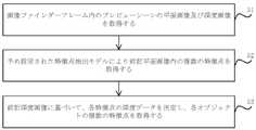
本実施例では、図2を参照すると、ステップ21において、電子機器内のプロセッサは、画像ファインダーフレーム内の各オブジェクトの複数の特徴点を取得することができ、効果は図3に示される。図3を参照すると、特徴点20は、画像ファインダーフレームにおける人物の肘及び画像ファインダーフレーム全体における肘の空間的位置(特徴点の座標データ及び他の特徴点との相対位置関係により表される)を表す。 In this embodiment, referring to FIG. 2, in
ここで、プロセッサが画像ファインダーフレーム内の各オブジェクトの複数の特徴点を取得するステップは、以下を含み得る。 Here, the step of the processor obtaining a plurality of feature points for each object in the image viewfinder frame may include: a.
一例では、電子機器には通常のカメラと深度カメラが設置され、これにより、通常のカメラは画像ファインダーフレーム内のプレビューシーンの平面画像を取得することができ、深度カメラはプレビューシーンの深度画像を取得することができる。図4を参照すると、ステップ41において、プロセッサは、通常のカメラ及び深度カメラとそれぞれ通信し、平面画像及び深度画像を取得することができる。ステップ42において、プロセッサは、深度画像及び平面画像に基づいて、プレビューシーンにおける各オブジェクトの複数の特徴点を取得することができ、これらの特徴点は、オブジェクトの輪郭、空間位置など、例えば、人物の頭及び肘、テーブルの足、室内の壁の隅などを反映することができる。なお、各特徴点の属性データは、3次元座標データ、他の特徴点との空間的関係データ、レンズとの空間的関係データなどを含み得て、具体的なシーンに応じて設定してもよいことが理解される。最後に、プロセッサは、複数の特徴点をプレビューシーンのオブジェクト上に挿入することができる。特徴点をプレビューシーンに挿入する過程は、関連技術を参照することができるため、ここではその説明を省略する。 In one example, a normal camera and a depth camera are installed in the electronic device, so that the normal camera can acquire a planar image of the preview scene in the image finder frame, and the depth camera can capture the depth image of the preview scene. can be obtained. Referring to FIG. 4, at
別の例では、電子機器には通常のカメラと深度カメラが設置され、これにより、通常のカメラはプレビューシーンの平面画像を取得することができ、深度カメラはプレビューシーンの深度画像を取得することができる。図5を参照すると、ステップ51において、プロセッサは、プレビューシーンの平面画像及び深度画像を取得することができる。ステップ52において、プロセッサは、予め設定された特徴点抽出モデル、例えばFASTアルゴリズム、SIFTアルゴリズム、SUFRアルゴリズム、ORBアルゴリズム、HARRISアルゴリズムなどを呼び出し、平面画像を当該特徴点抽出モデルに入力することで、平面画像内の複数の特徴点を取得することができる。なお、この場合、各特徴点の属性データは、2次元座標データ、他の特徴点との平面関係データ、レンズとの平面関係データなどを含み得ることが理解される。ステップ53において、プロセッサは、深度画像に基づいて各特徴点の深度データを決定し、さらに平面関係を空間関係に更新してもよく、すなわち、各特徴点が平面座標系から3次元座標系に遷移してもよく、この場合、各特徴点の属性データは、3次元座標データ、他の特徴点との空間的関係データ、レンズとの空間的関係データなどを含み得る。最後に、プロセッサは、複数の特徴点をプレビューシーンのオブジェクトに挿入することができる。 In another example, a normal camera and a depth camera are installed in the electronic device, so that the normal camera can obtain the planar image of the preview scene and the depth camera can obtain the depth image of the preview scene. can be done. Referring to FIG. 5, at
なお、本ステップの中核は、画像取得機能がオンにされた後、現在の通常撮影モード(すなわち、プレビューシーンにどのオブジェクトがあればどのオブジェクトを表示する)から仮想3次元空間に自動的に切り替えることによって、図3に示すような複数の特徴点を含む効果を実現することである。 Note that the core of this step is that after the image acquisition function is turned on, the current normal shooting mode (that is, which object is displayed if there is one in the preview scene) is automatically switched to the virtual three-dimensional space. By doing so, the effect of including a plurality of feature points as shown in FIG. 3 is realized.
引き続き図2を参照すると、ステップ22において、前記複数の特徴点のうちの1つをARアンカーポイントとして決定し、前記ARアンカーポイントが配置されたオブジェクトを被写体とし、ARアンカーポイントの位置が仮想3次元空間内の被写体の位置に対応する。本実施例では、電子機器において、プロセッサが表示装置と通信し、上記画像ファインダーフレームを表示するように表示装置を制御することで、複数の特徴点をユーザに示す。ユーザは、例えば図3の特徴点20をクリックするなど、ボタン又はタッチなどの方式で電子機器をトリガするように操作することができる。これにより、プロセッサは、トリガ操作に応じて、画像ファインダーフレーム内の1つの特徴点をARアンカーポイントとして決定することができる。当該ARアンカーポイントが配置されたオブジェクトを被写体とすることが理解される。又は、ユーザは、ARアンカーポイントを選択することで、仮想3次元空間から1つの被写体を選択した。 Continuing to refer to FIG. 2, in
ステップ13では、前記カメラモジュールの現在位置及び前記ARアンカーポイントに基づいて、前記画像ファインダーフレーム内で、仮想3次元空間内のカメラモジュールの所望の移動経路を表す移動撮影軌跡を生成する。 In
本実施例では、電子機器内のプロセッサが、電子機器内のレンズの現在位置及びARアンカーポイントに基づいて移動撮影軌跡を生成するステップは、以下を含む。 In this embodiment, the step of the processor in the electronic device generating the moving shooting trajectory based on the current position of the lens in the electronic device and the AR anchor point includes:
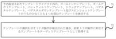
一例では、電子機器内にはテンプレートライブラリが予め設置され、当該テンプレートライブラリ内には、移動撮影軌跡のターゲット形状、基準ポイント及び移動撮影軌跡の相対位置を含むターゲットテンプレートのいくつかが含まれる。例えば、テンプレート1は、移動撮影軌跡の形状が円形であり、基準ポイントと移動撮影軌跡との相対位置が半径であることを含み、このテンプレート1は、スピンショットの移動撮影手法に対応する。テンプレート2は、移動撮影軌跡の形状が上から下に向かう垂直線分を含み、基準ポイントは垂直線分の上端点に位置し、このテンプレートはペデスタルダウンの移動撮影手法に対応し、テンプレート2の形状を逆にすれば、アップライトレンズの移動撮影手法に対応する。テンプレート3は、移動撮影の軌跡の形状が左から右への水平線分を含み、基準ポイントは水平線分の左端点であり、このテンプレートはトラックの移動撮影手法に対応する。なお、上記では、いくつかのテンプレートのみを挙げたが、例えば、トラック、パン・ティルト、ズームイン、ズームアウトなどの具体的な移動撮影手法に従って、対応するテンプレートを設定することができ、対応するテンプレートは、本開示の保護範囲に含まれる。 In one example, a template library is pre-installed in the electronic device, and the template library includes several target templates including the target shape of the moving shooting trajectory, the reference point and the relative position of the moving shooting trajectory. For example, the template 1 includes that the shape of the moving shooting trajectory is circular, and the relative position between the reference point and the moving shooting trajectory is the radius, and this template 1 corresponds to the spin shot moving shooting method. Template 2 includes a vertical line segment in which the shape of the moving shooting trajectory goes from top to bottom, and the reference point is located at the upper end point of the vertical line segment. If the shape is reversed, it corresponds to the moving photographing method of the upright lens. In the template 3, the locus shape of moving shooting includes a horizontal line segment from left to right, the reference point is the left end point of the horizontal line segment, and this template corresponds to the track moving shooting method. Although only a few templates have been mentioned above, corresponding templates can be set according to specific moving shooting techniques such as track, pan/tilt, zoom in and zoom out. is included in the protection scope of the present disclosure.
図6を参照すると、ステップ61において、プロセッサは、予め設定されたテンプレートライブラリからテンプレートを取得し、ターゲットテンプレートを取得することができ、取得方式は、以下を含み得て、図7を参照すると、ステップ71において、予め設定されたテンプレートライブラリ内のテンプレートを表示し、前記テンプレートは、ズームインテンプレート、ズームアウトテンプレート、パン・ティルトテンプレート、トラックテンプレート、ペデスタルテンプレート、ペデスタルダウンテンプレート及びスピンショットテンプレートのうちの少なくとも1つを含み、ステップ72において、テンプレートの選択を示すトリガ操作が検出された場合、前記トリガ操作に対応するテンプレートをターゲットテンプレートとして取得する。例えば、ステップ71において、プロセッサがARアンカーポイントを決定した後、ARアンカーポイントの位置又はARアンカーポイントに対応するオブジェクトに基づいて、テンプレートライブラリからいくつかのテンプレートを候補テンプレートとしてマッチングし、ARアンカーポイントの周囲に並列表示することができ、効果は図8に示され、ユーザ選択を容易にする。当然ながら、マッチング方式は、ランダムにいくつかの候補テンプレートを選択することもでき、ユーザの使用履歴に基づいて使用頻度の高いいくつかの候補テンプレートを選択することもでき、対応する方式は本開示の保護範囲に含まれる。ステップ72において、ユーザが候補テンプレートのうちの1つを操作することをトリガすると、プロセッサは、当該候補テンプレートをターゲットテンプレートとして決定することができる。したがって、ターゲットテンプレートは、移動撮影軌跡のターゲット形状、基準ポイントと移動撮影軌跡との相対位置を含む。 Referring to FIG. 6, in
ステップ62では、プロセッサは、ARアンカーポイントと基準ポイントとを重ね合わせることで、両者を一致させることができる。ARアンカーポイントと基準ポイントとが一致する場合、プロセッサは、レンズの現在位置を通過し、ターゲット形状にマッチングする移動撮影軌跡を生成することができ、効果は図9に示される。図9を参照すると、ユーザが人物上の特徴点20をARアンカーポイントとして選択し、テンプレート3を選択すると、左から右への1本の水平線分21を取得することができ、水平線分21からARアンカーポイントまでの水平距離はd(すなわち、基準ポイントと移動撮影軌跡との相対位置)である。 At
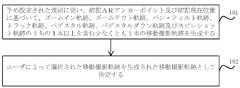
別の例では、電子機器内に予め設定された規則が記憶され、当該予め設定された規則は、移動撮影軌跡を生成するいくつかの規則を含み得る。例えば、ARアンカーポイントを中心として、現在位置を通過する円形、又は、予め設定された半径の円形を生成し、当該円形を移動撮影軌跡とする場合に、スピンショットの移動撮影手法に対応する。また、例えば、水平方向におけるARアンカーポイントからの距離dの基準ポイント又は現在位置を起点として、上から下に向かう垂直線分を生成し、当該垂直線分を移動撮影軌跡とする場合に、ペデスタルダウンの移動撮影手法に対応する。さらに、例えば、水平方向におけるARアンカーポイントからの距離dの基準ポイント又は現在位置を起点として、左から右への水平線分を生成し、当該水平線分を移動撮影軌跡とする場合に、トラックの移動撮影手法に対応する。なお、上記は、ほんの数例のみを挙げたが、例えば、トラック、パン・ティルト、ズームイン、ズームアウトなどの具体的な移動撮影手法に従って、対応する規則を設定することができ、対応する規則は、本開示の保護範囲に含まれる。 In another example, pre-set rules are stored in the electronic device, and the pre-set rules may include several rules for generating a moving shooting trajectory. For example, when a circle passing through the current position or a circle with a preset radius is generated with the AR anchor point as the center, and the circle is used as the moving shooting trajectory, it corresponds to the spin shot moving shooting method. Also, for example, when a vertical line segment is generated from top to bottom starting from the reference point or the current position at a distance d from the AR anchor point in the horizontal direction, and the vertical line segment is used as the moving shooting trajectory, the pedestal It corresponds to the moving shooting method of down. Furthermore, for example, when a horizontal line segment is generated from left to right starting from a reference point at a distance d from the AR anchor point in the horizontal direction or the current position, and the horizontal line segment is used as a moving shooting trajectory, the movement of the track It corresponds to the shooting method. It should be noted that the above are just a few examples, but corresponding rules can be set according to specific moving shooting techniques such as track, pan/tilt, zoom in, zoom out, etc. The corresponding rule is , fall within the protection scope of the present disclosure.
図10を参照すると、ステップ101において、プロセッサは、予め設定された規則に従い、ARアンカーポイント及び現在位置に基づいて少なくとも1本の移動撮影軌跡を生成することができ、効果は図11に示される。図11を参照すると、プロセッサは、移動撮影軌跡21及び移動撮影軌跡22を生成する。ステップ102において、プロセッサは、ユーザのトリガ操作を検出し、ユーザによって選択された移動撮影軌跡を、生成された移動撮影軌跡として決定することができる。 Referring to FIG. 10, in
実際の応用では、画像ファインダーフレーム内にいくつかのオブジェクトが含まれる場合があり、テンプレート又は予め設定された規則に従って移動撮影軌跡を生成することは、特定のオブジェクトを通過することがあり、そのため、ユーザは、移動撮影の行う過程に危険を起こすことがある。このために、一実施例では、図12を参照すると、ステップ121において、プロセッサは、移動撮影軌跡と画像ファインダーフレーム内のオブジェクトの位置とを比較することで、移動撮影軌跡にオブジェクトがあるか否かを決定することができる。ステップ122において、移動撮影軌跡にオブジェクトがある場合、プロセッサは、移動撮影軌跡におけるオブジェクトの周囲の部分を調整し、調整して得られた移動撮影軌跡を最終的な移動撮影軌跡としてもよいし、そうでない場合、調整を行わなくてもよい。このように、本実施例では、移動撮影軌跡を適応的に調整することで、移動撮影の撮影を確実に実現しつつ、ユーザの安全を確保することができる。 In practical application, there may be some objects in the image viewfinder frame, and generating the moving shooting trajectory according to the template or preset rules may pass through certain objects, so A user may take risks in the process of performing mobile photography. To this end, in one embodiment, referring to FIG. 12, at
ステップ14では、前記移動撮影軌跡に基づいて前記被写体を画像収集する。 In
本実施例では、ユーザは、移動撮影軌跡の案内に従い、被写体を画像取得し、例えば、映像や連写画像を撮影することができる。 In this embodiment, the user can acquire an image of the subject according to the guidance of the moving shooting trajectory, and can shoot a video or a continuous shooting image, for example.
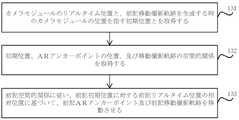
実際の応用では、画像ファインダーフレームが生成された後、ユーザは電子機器を動かす可能性があり、その際、図13を参照すると、ステップ131において、プロセッサはカメラモジュールのリアルタイム位置と、前記移動撮影軌跡を生成する時のカメラモジュールの位置を指す初期位置とを取得することができる。ステップ132において、プロセッサは、初期位置、ARアンカーポイントの位置、及び移動撮影軌跡の空間的関係を取得することができる。なお、移動撮影軌跡を取得する際に、初期位置、ARアンカーポイントの位置と移動撮影軌跡の3者の空間的関係が実際に取得されているので、その後に容易に使用するように、空間的関係を予め算出して指定位置に記憶することができる。ステップ133において、プロセッサは、前期空間的関係に基づいて、リアルタイム位置の初期位置に対する相対位置に従ってARアンカーポイント及び移動撮影軌跡を移動させることで、処理されるデータの数を減少させ、かつ移動撮影軌跡を動的に表示することによりユーザの使用体験を向上させるように、表示画面内の移動撮影軌跡の表示部分を調整することができる。 In practical application, the user may move the electronic device after the image viewfinder frame is generated, then, referring to FIG. An initial position, which refers to the position of the camera module when generating the trajectory, can be obtained. At
実際の応用では、移動撮影中に、ユーザ又はレンズは、移動撮影軌跡から外れる可能性がある。このため、本実施例では、図14を参照すると、ステップ141において、プロセッサは、撮影中において移動撮影軌跡にカメラモジュールが位置しているか否かを検出することができる。ステップ142において、移動撮影軌跡にカメラモジュールが位置していない場合、例えば、色、幅、破線実線、移動速度、ストロボなどの移動撮影軌跡の指定パラメータを調整することで、カメラモジュールが移動撮影軌跡から外れていることを気づかせ、効果は図15に示すとおりであり、ブロック23内の移動撮影軌跡が細くなり、移動撮影軌跡から離れたことをユーザに通知する。これにより、本実施例は、ユーザの正確な移動撮影を保証することができ、高品質の映像を得ることができる。 In practical applications, the user or the lens may deviate from the moving shooting trajectory during moving shooting. Therefore, in this embodiment, referring to FIG. 14, in
これまで、本実施例では、仮想現実シーン内に移動撮影軌跡を表示することで、ユーザが移動撮影軌跡に基づいて移動撮影手法を適用することに利便性を提供し、それにより高品質の映像を取得することができ、それとともに、本実施例では、追加のハードウェアを携帯する必要がなく、コストを削減し、また、ユーザには専門的な移動撮影知識が必要とされず、学習コストを削減し、撮影体験を向上させることにも役立つ。 So far, in this embodiment, by displaying the moving shooting trajectory in the virtual reality scene, it is convenient for the user to apply the moving shooting method based on the moving shooting trajectory, so that the high-quality video can be obtained. Along with this, the embodiment does not need to carry additional hardware, reducing costs, and the user does not need to have professional mobile photography knowledge, reducing learning costs. It also helps to reduce the noise and improve the shooting experience.
以下、様々な移動撮影手法と組み合わせて上記撮影方法の1つを説明し、以下を含む。 One of the above imaging methods is described below in combination with various mobile imaging techniques, including:
ズームイン又はズームアウト
撮影者が静止したまま、レンズは遠くから被写体へ移動すると表現され、
1.被写体と移動撮影テンプレートを選択し、
2.ARアンカーポイント、被写体を選択し、移動撮影軌跡を生成し、
3.撮影者は、移動撮影軌跡に従って移動して、画像収集を行うことで実現される。zoom in or zoom out The lens is described as moving from a distance to the subject while the photographer remains stationary.
1. Select a subject and a moving shooting template,
2. Select an AR anchor point and subject, generate a moving shooting trajectory,
3. This is realized by the photographer moving along the moving photographing trajectory and collecting images.
パン・ティルト
撮影者が移動し、レンズ位置が固定され、レンズ撮影角度は追従して移動すると表現され、
1.撮影者が被写体と移動撮影テンプレートを選択し、
2.被写体の位置を動的に認識し、位置に基づいてレンズを移動させて画像収集を行うことで実現される。Pan/Tilt It is expressed that the photographer moves, the lens position is fixed, and the lens shooting angle moves accordingly.
1. The photographer selects the subject and moving shooting template,
2. This is achieved by dynamically recognizing the position of the subject and moving the lens based on the position to acquire the image.
トラック
被写体とレンズとの距離を一定に保ち、レンズが被写体に追従して移動すると表現され、
1.撮影者がARアンカーポイント、被写体、及び移動撮影テンプレートを選択し、
2.ARアンカーポイントの固定距離及び方向で移動撮影軌跡を生成し、
3.映像の各フレームの構図における被写体の位置を検出し、撮影者が平行移動して画像収集を行うことで実現される。Track The distance between the subject and the lens is kept constant, and the lens follows the subject and moves.
1. The photographer selects the AR anchor point, subject, and moving shooting template,
2. Generate a moving shooting trajectory at a fixed distance and direction of the AR anchor point,
3. This is achieved by detecting the position of the subject in the composition of each frame of the video, and performing parallel movement by the photographer to collect the images.
ペデスタル
カメラ位置「上から下へ」又は「下から上へ」と表現され、
1.撮影者がARアンカーポイント、被写体、及び移動撮影テンプレートを選択し、
2.上から下又は下から上のいずれかに応じて、ARアンカーポイントの配置された高さが被写体の身長に関連付けられ、
3.固定距離を起点としたカメラ位置と移動撮影軌跡を表示して画像収集を行うことで実現される。The pedestal camera position is expressed as "top to bottom" or "bottom to top",
1. The photographer selects the AR anchor point, subject, and moving shooting template,
2. The height at which the AR anchor points are placed is related to the height of the subject, either top-to-bottom or bottom-to-top;
3. This is achieved by displaying the camera position and moving shooting trajectory with a fixed distance as the starting point and performing image acquisition.
上記撮影方法に加えて、本開示の実施例は、カメラモジュールが設けられる電子機器に適合される撮影装置をさらに提供し、図16を参照すると、前記装置は、
画像収集起動命令を受信するための命令受信モジュール161と、
前記電子機器の画像ファインダーフレーム内で、仮想3次元空間内の被写体の位置に対応するARアンカーポイントを作成するためのアンカーポイント作成モジュール162と、
前記カメラモジュールの現在位置及び前記ARアンカーポイントに基づいて、前記画像ファインダーフレーム内で、仮想3次元空間内のカメラモジュールの所望の移動経路を表す移動撮影軌跡を生成するための軌跡生成モジュール163と、
前記移動撮影軌跡に基づいて前記被写体を画像収集するための画像収集モジュール164と、を含む。In addition to the above photographing method, the embodiments of the present disclosure further provide a photographing device adapted to an electronic device equipped with a camera module, and referring to FIG. 16, the device comprises:
a
an anchor
a
and an
一実施例では、前記ARアンカーポイント作成モジュールは、
画像ファインダーフレーム内の各オブジェクトの複数の特徴点を取得するための特徴点の取得ユニットと、
前記複数の特徴点のうちの1つをARアンカーポイントとして決定するために用いられ、前記ARアンカーポイントが配置されたオブジェクトを被写体とし、前記ARアンカーポイントの位置が仮想3次元空間内の前記被写体の位置に対応するアンカーポイント決定ユニットと、を含む。In one embodiment, the AR anchor point creation module includes:
a feature point acquisition unit for acquiring a plurality of feature points of each object in the image viewfinder frame;
One of the plurality of feature points is used to determine an AR anchor point, an object on which the AR anchor point is arranged is taken as a subject, and the position of the AR anchor point is the subject in a virtual three-dimensional space. and an anchor point determination unit corresponding to the position of .
一実施例では、前記特徴点の取得ユニットは、
画像ファインダーフレーム内のプレビューシーンの平面画像及び深度画像を取得するための画像取得サブユニットと、
前記深度画像により前記プレビューシーン内の各オブジェクトの複数の特徴点を取得するための特徴点の取得サブユニットと、を含む。In one embodiment, the feature point acquisition unit comprises:
an image acquisition sub-unit for acquiring planar and depth images of the preview scene in the image viewfinder frame;
a feature point acquisition sub-unit for acquiring a plurality of feature points of each object in the preview scene from the depth image.
一実施例では、前記特徴点の取得ユニットは、
画像ファインダーフレーム内のプレビューシーンの平面画像及び深度画像を取得するための画像取得サブユニットと、
予め設定された特徴点抽出モデルにより前記平面画像内の複数の特徴点を取得するための特徴点抽出サブユニットと、
前記深度画像に基づいて、各特徴点の深度データを決定し、各オブジェクトの複数の特徴点を取得するための特徴点決定サブユニットと、を含む。In one embodiment, the feature point acquisition unit comprises:
an image acquisition sub-unit for acquiring planar and depth images of the preview scene in the image viewfinder frame;
a feature point extraction sub-unit for obtaining a plurality of feature points in the planar image according to a preset feature point extraction model;
a feature point determination sub-unit for determining depth data for each feature point based on the depth image and obtaining a plurality of feature points for each object.
一実施例では、前記軌跡生成モジュールは、
予め設定されたテンプレートライブラリから、移動撮影軌跡のターゲット形状、基準ポイント及び移動撮影軌跡の相対位置を含むターゲットテンプレートを取得するためのモジュール取得ユニットと、
前記ARアンカーポイントと前記基準ポイントとが重なった場合、前記現在位置を通過し、かつ前記ターゲットの形状にマッチングする移動撮影軌跡を生成するための軌跡生成ユニットと、を含む。In one embodiment, the trajectory generation module comprises:
a module obtaining unit for obtaining a target template including the target shape of the moving shooting trajectory, the reference point and the relative position of the moving shooting trajectory from a preset template library;
a trajectory generating unit for generating a moving shooting trajectory that passes through the current position and matches the shape of the target when the AR anchor point and the reference point overlap.
一実施例では、前記モジュール取得ユニットは、
予め設定されたテンプレートライブラリ内の、ズームインテンプレート、ズームアウトテンプレート、パン・ティルトテンプレート、トラックテンプレート、ペデスタルテンプレート、ペデスタルダウンテンプレート及びスピンショットテンプレートのうちの少なくとも1つを含むテンプレートを表示するためのテンプレート表示サブユニットと、
テンプレートの選択を示すトリガ操作が検出された場合、前記トリガ操作に対応するテンプレートをターゲットテンプレートとして取得するためのテンプレート決定サブユニットと、を含む。In one embodiment, the module acquisition unit comprises:
A template display for displaying templates in a preset template library, including at least one of a zoom-in template, a zoom-out template, a pan-tilt template, a track template, a pedestal template, a pedestal-down template, and a spinshot template. a subunit and
a template determining subunit for obtaining a template corresponding to the triggering operation as a target template when a triggering operation indicating selection of a template is detected.
一実施例では、前記軌跡生成モジュールは、
予め設定された規則に従い、前記ARアンカーポイント及び前記現在位置に基づいて、ズームイン軌跡、ズームアウト軌跡、パン・ティルト軌跡、トラック軌跡、ペデスタル軌跡、ペデスタルダウン軌跡及びスピンショット軌跡のうちの1本以上を含む少なくとも1本の移動撮影軌跡を生成するための軌跡生成ユニットと、
ユーザによって選択された移動撮影軌跡を生成された移動撮影軌跡として決定するための軌跡決定ユニットと、を含む。In one embodiment, the trajectory generation module comprises:
One or more of a zoom-in trajectory, a zoom-out trajectory, a pan-tilt trajectory, a track trajectory, a pedestal trajectory, a pedestal-down trajectory, and a spin shot trajectory, based on the AR anchor point and the current position according to preset rules. a trajectory generation unit for generating at least one mobile shooting trajectory comprising
a trajectory determination unit for determining the mobile shooting trajectory selected by the user as the generated mobile shooting trajectory.
一実施例では、前記装置は、
前記移動撮影軌跡を前記画像ファインダーフレーム内の各オブジェクトの位置と比較するための位置比較モジュールと、
前記移動撮影軌跡にオブジェクトが存在する場合、前記移動撮影軌跡が前記オブジェクトから回避するように、前記オブジェクトの周囲における前記移動撮影軌跡の部分を調整するための軌跡調整モジュールと、をさらに含む。In one embodiment, the device comprises:
a position comparison module for comparing the moving shooting trajectory with the position of each object in the image viewfinder frame;
a trajectory adjustment module for adjusting a portion of the moving shooting trajectory around the object such that the moving shooting trajectory avoids the object if an object exists in the moving shooting trajectory.
一実施例では、前記画像収集モジュールは、
カメラモジュールのリアルタイム位置と、前記移動撮影軌跡を生成する時のカメラモジュールの位置を指す初期位置とを取得するための位置取得ユニットと、
初期位置、ARアンカーポイントの位置、及び移動撮影軌跡の空間的関係を取得するための関係取得ユニットと、
前記空間的関係に従い、前記初期位置に対する前記リアルタイム位置の相対位置に基づいて、前記ARアンカーポイント及び前記移動撮影軌跡を移動させるための軌跡移動ユニットと、を含む。In one embodiment, the image acquisition module comprises:
a position acquisition unit for acquiring a real-time position of a camera module and an initial position, which refers to the position of the camera module when generating the moving shooting trajectory;
a relationship acquisition unit for acquiring a spatial relationship between the initial position, the position of the AR anchor point, and the moving shooting trajectory;
a trajectory moving unit for moving the AR anchor point and the moving shooting trajectory according to the spatial relationship and based on the relative position of the real-time position to the initial position.
一実施例では、前記画像収集モジュールは、
撮影中に、前記移動撮影軌跡にカメラモジュールが位置するか否かを検出するための軌跡検出ユニットと、
前記移動撮影軌跡に前記カメラモジュールが位置していない場合、前記カメラモジュールが前記移動撮影軌跡から外れていることを通知するように、前記移動撮影軌跡の指定パラメータを調整するための軌跡調整ユニットと、を含む。In one embodiment, the image acquisition module comprises:
a trajectory detection unit for detecting whether the camera module is positioned on the moving photography trajectory during photography;
a trajectory adjustment unit for adjusting a specified parameter of the moving shooting trajectory so as to notify that the camera module is out of the moving shooting trajectory when the camera module is not positioned on the moving shooting trajectory; ,including.
本開示の実施例にて提供される装置は、上記方法に対応し、具体的な内容は、方法の各実施例の内容を参照することができ、ここでその説明を省略することが理解される。 It is understood that the apparatus provided in the embodiments of the present disclosure corresponds to the above method, and the specific content can refer to the content of each embodiment of the method, and the description thereof will be omitted here. be.
図17は、例示的な実施例にて示される電子機器のブロック図である。例えば、電子機器1700は、スマートフォン、コンピュータ、デジタル放送用端末、タブレット機器、医療機器、フィットネス機器、携帯情報端末などであってもよい。 FIG. 17 is a block diagram of electronics shown in an exemplary embodiment. For example, the
図17を参照すると、電子機器1700は、処理コンポーネント1702と、メモリ1704と、電源コンポーネント1706と、マルチメディアコンポーネント1708と、オーディオコンポーネント1710と、入出力(I/O)インタフェース1712と、センサコンポーネント1714と、通信コンポーネント1716と、画像取得コンポーネント1718とのうちの1つ以上を含み得る。 Referring to FIG. 17, the
処理コンポーネント1702は、一般的に、表示、電話の呼び出し、データ通信、カメラ操作、及び録音操作に関連する操作など、電子機器1700の全体的な操作を制御する。処理コンポーネント1702は、コンピュータプログラムを実行する1つ以上のプロセッサ1710を含み得る。さらに、処理コンポーネント1702は、処理コンポーネント1702と他のコンポーネントとの間の対話を容易にする1つ以上のモジュールを含み得る。例えば、処理コンポーネント1702は、マルチメディアコンポーネント1708と処理コンポーネント1702との間の対話を容易にするためにマルチメディアモジュールを含み得る。
メモリ1704は、電子機器1700の操作をサポートするために様々なデータを記憶するように構成される。これらのデータの例は、電子機器1700上で操作するための任意のアプリケーションプログラム又は方法のコンピュータプログラム、連絡先データ、電話帳データ、メッセージ、ピクチャー、映像などを含む。メモリ1704は、スタティックランダムアクセスメモリ(SRAM)、電気的消去可能プログラマブル読み出し専用メモリ(EEPROM)、消去可能プログラマブル読み出し専用メモリ(EPROM)、プログラマブル読み出し専用メモリ(PROM)、読み出し専用メモリ(ROM)、磁気メモリ、フラッシュメモリ、磁気ディスク、又は光ディスクのような任意のタイプの揮発性又は不揮発性記憶機器、又はそれらの組み合わせによって実現され得る。
電源コンポーネント1706は、電子機器1700の様々なコンポーネントに電力を供給する。電源コンポーネント1706は、電力管理システム、1つ以上の電源、及び電子機器1700への電力の生成、管理、及び分配に関連する他のコンポーネントを含み得る。電源コンポーネント1706は、コントローラと通信して、電池が主要ボード回路に電力を供給するか、又は供給しないように、スイッチングデバイスをオン又はオフに制御することができる電源チップを含み得る。
マルチメディアコンポーネント1708は、電子機器1700とターゲットオブジェクトとの間の出力インタフェースを提供するスクリーンを含む。いくつかの実施例では、スクリーンは、液晶表示画面(LCD)及びタッチパネル(TP)を含み得る。スクリーンがタッチパネルを含む場合、スクリーンは、ターゲットオブジェクトから入力信号を受信するためのタッチスクリーンとして実現され得る。タッチパネルは、タッチ、スライド、及びタッチパネル上のジェスチャを感知するための1つ又は複数のタッチセンサを含む。タッチセンサは、タッチ又はスライド動作の境界を感知するだけでなく、タッチ又はスライド動作に係る継続時間及び圧力を検出することができる。
オーディオコンポーネント1710は、オーディオ信号を出力及び/又は入力するように構成される。例えば、オーディオコンポーネント1710は、マイクロフォン(MIC)を含み、電子機器1700が呼び出しモード、録音モード、及び音声認識モードなどの操作モードにある場合に、マイクロフォンは、外部オーディオ信号を受信するように構成される。受信されたオーディオ信号は、メモリ1704にさらに記憶され得るか、又は通信コンポーネント1716を介して送信され得る。いくつかの実施例では、オーディオコンポーネント1710は、オーディオ信号を出力するためのスピーカーをさらに含む。
I/Oインタフェース1712は、処理コンポーネント1702と、キーボード、クリックホイール、ボタンなどであり得る周辺インタフェースモジュールとの間のインタフェースを提供する。 I/
センサコンポーネント1714は、電子機器1700の様々な態様の状態評価を提供するための1つ以上のセンサを含む。例えば、センサコンポーネント1714は、電子機器1700のオンオフ状態、コンポーネントの相対位置、例えば、コンポーネントが電子機器1700の表示画面及びキーパッドであることを検出することができ、センサコンポーネント1714は、電子機器1700又はコンポーネントの位置の変化、ターゲットオブジェクトが電子機器1700と接触することの有無、電子機器1700の向き又は加速/減速、及び電子機器1700の温度の変化をさらに検出することができる。本実施例で、センサコンポーネント1714は、磁気センサ、ジャイロスコープ、及び磁場センサを含み得て、ここで、磁場センサは、ホールセンサ、薄膜磁気抵抗センサ、及び磁気液体加速度センサのうちの少なくとも1つを含む。
通信コンポーネント1716は、電子機器1700と他の機器との間の有線又は無線通信を容易にするように構成される。電子機器1700は、WiFi、2G、3G、4G、5G、又はそれらの組み合わせなどの通信規格に基づくワイヤレスネットワークにアクセスすることができる。例示的な一実施例では、通信コンポーネント1716は、ブロードキャストチャネルを介して外部のブロードキャスト管理システムからブロードキャスト信号又はブロードキャスト関連情報を受信する。例示的な一実施例では、通信コンポーネント1716は、近距離通信を容易にするための近距離無線通信(NFC)モジュールをさらに含む。例えば、NFCモジュールは、無線周波数識別(RFID)技術、赤外線データアソシエーション(IrDA)技術、超広帯域(UWB)技術、ブルートゥース(登録商標)(BT)技術及びその他の技術に基づいて実現され得る。
例示的な実施例では、電子機器1700は、1つ以上のアプリケーション特定用途向け集積回路(ASIC)、デジタル信号プロセッサ(DSP)、デジタル信号処理デバイス(DSPD)、プログラマブル論理デバイス(PLD)、フィールドプログラマブルゲートアレイ(FPGA)、コントローラ、マイクロコントローラ、マイクロプロセッサ、又は他の電子デバイスによって実現され得る。 In the exemplary embodiment,
例示的な実施例では、例えば、命令を含むメモリ1704などの実行可能なコンピュータプログラムを含む非一時的読み取り可能な記憶媒体をさらに提供し、上記実行可能なコンピュータプログラムは、プロセッサによって実行されて、上記方法を実施することができる。ここで、読み取り可能な記憶媒体は、ROM、ランダムアクセスメモリ(RAM)、CD-ROM、磁気テープ、フロッピーディスク、光データ記憶デバイスなどであってもよい。 Exemplary embodiments further provide a non-transitory readable storage medium containing an executable computer program, e.g.,
当業者は、明細書を検討し、本明細書に開示された開示を実施した後、本開示の他の実施形態を容易に想到し得る。本開示は、任意の変形、使用、又は適応的変更を包含することを意図しており、これらの変形、使用、又は適応的変更は本開示の一般原則に従い、本開示に開示されていない技術分野での常識又は慣用されている技術的手段を含む。本明細書及び実施例は、単に例示として見なされるものであり、本開示の真の範囲及び精神は、以下の特許請求の範囲によって示される。 Other embodiments of the present disclosure may readily occur to those skilled in the art, after reviewing the specification and practicing the disclosure disclosed herein. This disclosure is intended to cover any variations, uses, or adaptations that follow the general principles of this disclosure, and which incorporate techniques not disclosed in this disclosure. Including common sense or customary technical means in the field. It is intended that the specification and examples be considered as exemplary only, with a true scope and spirit of the disclosure being indicated by the following claims.
本開示は、上記で記述され、図面に示された厳密な構造に限定されず、その範囲から逸脱することなく、様々な修正及び変更がなされ得ることを理解されたい。本開示の範囲は、添付の特許請求の範囲のみによって限定される。 It is to be understood that this disclosure is not limited to the precise constructions described above and shown in the drawings, and that various modifications and changes may be made without departing from its scope. The scope of the disclosure is limited only by the appended claims.
(付記)
(付記1)
撮影方法であって、カメラモジュールが設けられる電子機器に適用され、前記方法は、
画像収集起動命令を受信するステップと、
前記電子機器の画像ファインダーフレーム内で、仮想3次元空間内の被写体の位置に対応するARアンカーポイントを作成するステップと、
前記カメラモジュールの現在位置及び前記ARアンカーポイントに基づいて、前記画像ファインダーフレーム内で、仮想3次元空間内のカメラモジュールの所望の移動経路を表す移動撮影軌跡を生成するステップと、
前記移動撮影軌跡に基づいて前記被写体を画像収集するステップと、を含む、
ことを特徴とする撮影方法。(Appendix)
(Appendix 1)
A photographing method, applied to an electronic device provided with a camera module, the method comprising:
receiving an image acquisition activation command;
creating an AR anchor point in the image viewfinder frame of the electronic device that corresponds to the position of the subject in the virtual three-dimensional space;
generating a moving shooting trajectory representing a desired moving path of the camera module in a virtual three-dimensional space within the image viewfinder frame based on the current position of the camera module and the AR anchor point;
acquiring images of the subject based on the moving shooting trajectory;
A photographing method characterized by:
(付記2)
前記電子機器の画像ファインダーフレーム内でARアンカーポイントを作成するステップは、
画像ファインダーフレーム内の各オブジェクトの複数の特徴点を取得するステップと、
前記複数の特徴点のうちの1つをARアンカーポイントとして決定し、前記ARアンカーポイントが配置されたオブジェクトを被写体とし、前記ARアンカーポイントの位置が仮想3次元空間内の前記被写体の位置に対応するステップと、を含む、
ことを特徴とする付記1に記載の撮影方法。(Appendix 2)
creating an AR anchor point within an image viewfinder frame of the electronic device comprising:
obtaining a plurality of feature points for each object in the image viewfinder frame;
One of the plurality of feature points is determined as an AR anchor point, the object on which the AR anchor point is arranged is set as a subject, and the position of the AR anchor point corresponds to the position of the subject in a virtual three-dimensional space. and
The imaging method according to Supplementary Note 1, characterized by:
(付記3)
画像ファインダーフレーム内の各オブジェクトの複数の特徴点を取得するステップは、
画像ファインダーフレーム内のプレビューシーンの平面画像及び深度画像を取得するステップと、
前記深度画像により前記プレビューシーン内の各オブジェクトの複数の特徴点を取得するステップと、を含む、
ことを特徴とする付記2に記載の撮影方法。(Appendix 3)
Obtaining a plurality of feature points for each object in the image viewfinder frame comprises:
obtaining planar and depth images of the preview scene in the image viewfinder frame;
obtaining a plurality of feature points of each object in the preview scene from the depth image;
The photographing method according to appendix 2, characterized by:
(付記4)
画像ファインダーフレーム内の各オブジェクトの複数の特徴点を取得するステップは、
画像ファインダーフレーム内のプレビューシーンの平面画像及び深度画像を取得するステップと、
予め設定された特徴点抽出モデルにより前記平面画像内の複数の特徴点を取得するステップと、
前記深度画像に基づいて、各特徴点の深度データを決定し、各オブジェクトの複数の特徴点を取得するステップと、を含む、
ことを特徴とする付記2に記載の撮影方法。(Appendix 4)
Obtaining a plurality of feature points for each object in the image viewfinder frame comprises:
obtaining planar and depth images of the preview scene in the image viewfinder frame;
obtaining a plurality of feature points in the planar image according to a preset feature point extraction model;
determining depth data for each feature point based on the depth image to obtain a plurality of feature points for each object;
The photographing method according to appendix 2, characterized by:
(付記5)
前記カメラモジュールの現在位置及び前記ARアンカーポイントに基づいて、前記画像ファインダーフレーム内で移動撮影軌跡を生成するステップは、
予め設定されたテンプレートライブラリから、移動撮影軌跡のターゲット形状、基準ポイント及び移動撮影軌跡の相対位置を含むターゲットテンプレートを取得するステップと、
前記ARアンカーポイントと前記基準ポイントとが重なった場合、前記現在位置を通過し、かつ前記ターゲットの形状にマッチングする移動撮影軌跡を生成するステップと、を含む、
ことを特徴とする付記1に記載の撮影方法。(Appendix 5)
generating a moving shooting trajectory within the image viewfinder frame based on the current position of the camera module and the AR anchor point;
obtaining a target template including a target shape of the moving shooting trajectory, a reference point and a relative position of the moving shooting trajectory from a preset template library;
generating a moving shooting trajectory that passes through the current position and matches the shape of the target when the AR anchor point and the reference point overlap;
The imaging method according to Supplementary Note 1, characterized by:
(付記6)
予め設定されたテンプレートライブラリからターゲットテンプレートを取得するステップは、
予め設定されたテンプレートライブラリ内のテンプレートを表示するステップであって、前記テンプレートは、ズームインテンプレート、ズームアウトテンプレート、パン・ティルトテンプレート、トラックテンプレート、ペデスタルテンプレート、ペデスタルダウンテンプレート及びスピンショットテンプレートのうちの少なくとも1つを含むステップと、
テンプレートの選択を示すトリガ操作が検出された場合、前記トリガ操作に対応するテンプレートをターゲットテンプレートとして取得するステップと、を含む、
ことを特徴とする付記5に記載の撮影方法。(Appendix 6)
The step of obtaining a target template from a preset template library includes:
displaying templates in a pre-configured template library, said templates being at least one of a zoom-in template, a zoom-out template, a pan-tilt template, a track template, a pedestal template, a pedestal down template and a spin shot template; a step comprising one;
when a trigger operation indicating selection of a template is detected, obtaining a template corresponding to the trigger operation as a target template;
The photographing method according to appendix 5, characterized by:
(付記7)
前記カメラモジュールの現在位置及び前記ARアンカーポイントに基づいて、前記画像ファインダーフレーム内で移動撮影軌跡を生成するステップは、
予め設定された規則に従い、前記ARアンカーポイント及び前記現在位置に基づいて、少なくとも1本の移動撮影軌跡を生成するステップであって、前記移動撮影軌跡は、ズームイン軌跡、ズームアウト軌跡、パン・ティルト軌跡、トラック軌跡、ペデスタル軌跡、ペデスタルダウン軌跡及びスピンショット軌跡のうちの1本以上を含むステップと、
ユーザによって選択された移動撮影軌跡を生成された移動撮影軌跡として決定するステップと、を含む、
ことを特徴とする付記1に記載の撮影方法。(Appendix 7)
generating a moving shooting trajectory within the image viewfinder frame based on the current position of the camera module and the AR anchor point;
generating at least one moving shooting trajectory based on the AR anchor point and the current position according to a preset rule, wherein the moving shooting trajectory includes a zoom-in trajectory, a zoom-out trajectory, and a pan/tilt comprising one or more of a trajectory, a track trajectory, a pedestal trajectory, a pedestal down trajectory and a spin shot trajectory;
determining the mobile shooting trajectory selected by the user as the generated mobile shooting trajectory;
The imaging method according to Supplementary Note 1, characterized by:
(付記8)
移動撮影軌跡を生成した後に、前記方法は、
前記移動撮影軌跡を前記画像ファインダーフレーム内の各オブジェクトの位置と比較するステップと、
前記移動撮影軌跡にオブジェクトが存在する場合、前記移動撮影軌跡が前記オブジェクトから回避するように、前記オブジェクトの周囲における前記移動撮影軌跡の部分を調整するステップと、をさらに含む、
ことを特徴とする付記1~7のいずれか1つに記載の撮影方法。(Appendix 8)
After generating the moving shooting trajectory, the method includes:
comparing the moving shooting trajectory with the position of each object in the image viewfinder frame;
adjusting a portion of the moving shooting trajectory around the object, if an object exists in the moving shooting trajectory, such that the moving shooting trajectory avoids the object;
The photographing method according to any one of Appendices 1 to 7, characterized in that:
(付記9)
前記移動撮影軌跡に基づいて前記被写体を画像収集するステップは、
カメラモジュールのリアルタイム位置と、前記移動撮影軌跡を生成する時のカメラモジュールの位置を指す初期位置とを取得するステップと、
初期位置、ARアンカーポイントの位置、及び移動撮影軌跡の空間的関係を取得するステップと、
前記空間的関係に従い、前記初期位置に対する前記リアルタイム位置の相対位置に基づいて、前記ARアンカーポイント及び前記移動撮影軌跡を移動させるステップと、を含む、
ことを特徴とする付記1~7のいずれか1つに記載の撮影方法。(Appendix 9)
The step of acquiring images of the subject based on the moving shooting trajectory includes:
obtaining a real-time position of a camera module and an initial position, which refers to the position of the camera module when generating the moving shooting trajectory;
obtaining a spatial relationship between the initial position, the position of the AR anchor point, and the moving shooting trajectory;
moving the AR anchor point and the moving shooting trajectory according to the spatial relationship and based on the relative position of the real-time position to the initial position;
The photographing method according to any one of Appendices 1 to 7, characterized in that:
(付記10)
前記移動撮影軌跡に基づいて前記被写体を画像収集するステップは、
撮影中に、前記移動撮影軌跡にカメラモジュールが位置するか否かを検出するステップと、
前記移動撮影軌跡に前記カメラモジュールが位置していない場合、前記カメラモジュールが前記移動撮影軌跡から外れていることを通知するように、前記移動撮影軌跡の指定パラメータを調整するステップと、を含む、
ことを特徴とする付記1に記載の撮影方法。(Appendix 10)
The step of acquiring images of the subject based on the moving shooting trajectory includes:
detecting whether the camera module is positioned on the moving shooting trajectory during shooting;
adjusting a specified parameter of the moving shooting trajectory so as to notify that the camera module is out of the moving shooting trajectory when the camera module is not positioned on the moving shooting trajectory;
The imaging method according to Supplementary Note 1, characterized by:
(付記11)
撮影装置であって、カメラモジュールが設けられる電子機器に適用され、前記装置は、
画像収集起動命令を受信するための命令受信モジュールと、
前記電子機器の画像ファインダーフレーム内で、仮想3次元空間内の被写体の位置に対応するARアンカーポイントを作成するためのアンカーポイント作成モジュールと、
前記カメラモジュールの現在位置及び前記ARアンカーポイントに基づいて、前記画像ファインダーフレーム内で、仮想3次元空間内のカメラモジュールの所望の移動経路を表す移動撮影軌跡を生成するための軌跡生成モジュールと、
前記移動撮影軌跡に基づいて前記被写体を画像収集するための画像収集モジュールと、を含む、
ことを特徴とする撮影装置。(Appendix 11)
A photographing device applied to an electronic device provided with a camera module, the device comprising:
an instruction receiving module for receiving an image acquisition activation instruction;
an anchor point creation module for creating an AR anchor point corresponding to a position of a subject in a virtual three-dimensional space within an image finder frame of the electronic device;
a trajectory generation module for generating a moving shooting trajectory representing a desired movement path of the camera module in a virtual three-dimensional space within the image viewfinder frame based on the current position of the camera module and the AR anchor point;
an image acquisition module for acquiring images of the subject based on the moving shooting trajectory;
An imaging device characterized by:
(付記12)
前記アンカーポイント作成モジュールは、
画像ファインダーフレーム内の各オブジェクトの複数の特徴点を取得するための特徴点の取得ユニットと、
前記複数の特徴点のうちの1つをARアンカーポイントとして決定するために用いられ、前記ARアンカーポイントが配置されたオブジェクトを被写体とし、前記ARアンカーポイントの位置が仮想3次元空間内の前記被写体の位置に対応するアンカーポイント決定ユニットと、を含む、
ことを特徴とする付記11に記載の撮影装置。(Appendix 12)
The anchor point creation module includes:
a feature point acquisition unit for acquiring a plurality of feature points of each object in the image viewfinder frame;
One of the plurality of feature points is used to determine an AR anchor point, an object on which the AR anchor point is arranged is taken as a subject, and the position of the AR anchor point is the subject in a virtual three-dimensional space. an anchor point determination unit corresponding to the position of
The photographing device according to appendix 11, characterized by:
(付記13)
前記特徴点の取得ユニットは、
画像ファインダーフレーム内のプレビューシーンの平面画像及び深度画像を取得するための画像取得サブユニットと、
前記深度画像により前記プレビューシーン内の各オブジェクトの複数の特徴点を取得するための特徴点の取得サブユニットと、を含む、
ことを特徴とする付記12に記載の撮影装置。(Appendix 13)
The feature point acquisition unit includes:
an image acquisition sub-unit for acquiring planar and depth images of the preview scene in the image viewfinder frame;
a feature point acquisition sub-unit for acquiring a plurality of feature points of each object in the preview scene from the depth image;
13. The photographing device according to
(付記14)
前記特徴点の取得ユニットは、
画像ファインダーフレーム内のプレビューシーンの平面画像及び深度画像を取得するための画像取得サブユニットと、
予め設定された特徴点抽出モデルにより前記平面画像内の複数の特徴点を取得するための特徴点抽出サブユニットと、
前記深度画像に基づいて、各特徴点の深度データを決定し、各オブジェクトの複数の特徴点を取得するための特徴点決定サブユニットと、を含む、
ことを特徴とする付記12に記載の撮影装置。(Appendix 14)
The feature point acquisition unit includes:
an image acquisition sub-unit for acquiring planar and depth images of the preview scene in the image viewfinder frame;
a feature point extraction sub-unit for obtaining a plurality of feature points in the planar image according to a preset feature point extraction model;
a feature point determination sub-unit for determining depth data for each feature point based on the depth image to obtain a plurality of feature points for each object;
13. The photographing device according to
(付記15)
前記軌跡生成モジュールは、
予め設定されたテンプレートライブラリから、移動撮影軌跡のターゲット形状、基準ポイント及び移動撮影軌跡の相対位置を含むターゲットテンプレートを取得するためのモジュール取得ユニットと、
前記ARアンカーポイントと前記基準ポイントとが重なった場合、前記現在位置を通過し、かつ前記ターゲットの形状にマッチングする移動撮影軌跡を生成するための軌跡生成ユニットと、を含む、
ことを特徴とする付記11に記載の撮影装置。(Appendix 15)
The trajectory generation module is
a module obtaining unit for obtaining a target template including the target shape of the moving shooting trajectory, the reference point and the relative position of the moving shooting trajectory from a preset template library;
a trajectory generation unit for generating a moving shooting trajectory that passes through the current position and matches the shape of the target when the AR anchor point and the reference point overlap;
The photographing device according to appendix 11, characterized by:
(付記16)
前記モジュール取得ユニットは、
予め設定されたテンプレートライブラリ内のテンプレートを表示するためのテンプレート表示サブユニットであって、前記テンプレートは、ズームインテンプレート、ズームアウトテンプレート、パン・ティルトテンプレート、トラックテンプレート、ペデスタルテンプレート、ペデスタルダウンテンプレート及びスピンショットテンプレートのうちの少なくとも1つを含むテンプレート表示サブユニットと、
テンプレートの選択を示すトリガ操作が検出された場合、前記トリガ操作に対応するテンプレートをターゲットテンプレートとして取得するためのテンプレート決定サブユニットと、を含む、
ことを特徴とする付記15に記載の撮影装置。(Appendix 16)
The module acquisition unit is
A template display sub-unit for displaying templates in a preset template library, said templates being zoom-in template, zoom-out template, pan-tilt template, track template, pedestal template, pedestal down template and spin shot. a template display subunit including at least one of the templates;
a template determination sub-unit for obtaining a template corresponding to the trigger operation as a target template if a trigger operation indicating selection of a template is detected;
16. The photographing device according to appendix 15, characterized by:
(付記17)
前記軌跡生成モジュールは、
予め設定された規則に従い、前記ARアンカーポイント及び前記現在位置に基づいて、少なくとも1本の移動撮影軌跡を生成するための軌跡生成ユニットであって、前記移動撮影軌跡は、ズームイン軌跡、ズームアウト軌跡、パン・ティルト軌跡、トラック軌跡、ペデスタル軌跡、ペデスタルダウン軌跡及びスピンショット軌跡のうちの1本以上を含む軌跡生成ユニットと、
ユーザによって選択された移動撮影軌跡を生成された移動撮影軌跡として決定するための軌跡決定ユニットと、を含む、
ことを特徴とする付記11に記載の撮影装置。(Appendix 17)
The trajectory generation module is
a trajectory generation unit for generating at least one moving shooting trajectory based on the AR anchor point and the current position according to a preset rule, wherein the moving shooting trajectory comprises a zoom-in trajectory and a zoom-out trajectory; , a pan-tilt trajectory, a track trajectory, a pedestal trajectory, a pedestal-down trajectory and a spin-shot trajectory;
a trajectory determination unit for determining the mobile shooting trajectory selected by the user as the generated mobile shooting trajectory;
The photographing device according to appendix 11, characterized by:
(付記18)
前記移動撮影軌跡を前記画像ファインダーフレーム内の各オブジェクトの位置と比較するための位置比較モジュールと、
前記移動撮影軌跡にオブジェクトが存在する場合、前記移動撮影軌跡が前記オブジェクトから回避するように、前記オブジェクトの周囲における前記移動撮影軌跡の部分を調整するための軌跡調整モジュールと、をさらに含む、
ことを特徴とする付記11~17のいずれか1つに記載の撮影装置。(Appendix 18)
a position comparison module for comparing the moving shooting trajectory with the position of each object in the image viewfinder frame;
a trajectory adjustment module for adjusting a portion of the moving shooting trajectory around the object such that the moving shooting trajectory avoids the object when an object is present in the moving shooting trajectory;
18. The photographing device according to any one of appendices 11 to 17, characterized by:
(付記19)
前記画像収集モジュールは、
カメラモジュールのリアルタイム位置と、前記移動撮影軌跡を生成する時のカメラモジュールの位置を指す初期位置とを取得するための位置取得ユニットと、
初期位置、ARアンカーポイントの位置、及び移動撮影軌跡の空間的関係を取得するための関係取得ユニットと、
前記空間的関係に従い、前記初期位置に対する前記リアルタイム位置の相対位置に基づいて、前記ARアンカーポイント及び前記移動撮影軌跡を移動させるための軌跡移動ユニットと、を含む、
ことを特徴とする付記11~17のいずれか1つに記載の撮影装置。(Appendix 19)
The image acquisition module includes:
a position acquisition unit for acquiring a real-time position of a camera module and an initial position that refers to the position of the camera module when generating the moving shooting trajectory;
a relationship acquisition unit for acquiring a spatial relationship between the initial position, the position of the AR anchor point, and the moving shooting trajectory;
a trajectory movement unit for moving the AR anchor point and the moving shooting trajectory according to the spatial relationship and based on the relative position of the real-time position to the initial position;
18. The photographing device according to any one of appendices 11 to 17, characterized by:
(付記20)
前記画像収集モジュールは、
撮影中に、前記移動撮影軌跡にカメラモジュールが位置するか否かを検出するための軌跡検出ユニットと、
前記移動撮影軌跡に前記カメラモジュールが位置していない場合、前記カメラモジュールが前記移動撮影軌跡から外れていることを通知するように、前記移動撮影軌跡の指定パラメータを調整するための軌跡調整ユニットと、を含む、
ことを特徴とする付記11に記載の撮影装置。(Appendix 20)
The image acquisition module includes:
a trajectory detection unit for detecting whether the camera module is positioned on the moving photography trajectory during photography;
a trajectory adjustment unit for adjusting a specified parameter of the moving shooting trajectory so as to notify that the camera module is out of the moving shooting trajectory when the camera module is not positioned on the moving shooting trajectory; ,including,
The photographing device according to appendix 11, characterized by:
(付記21)
電子機器であって、
カメラと、
プロセッサと、
前記プロセッサによって実行可能なコンピュータプログラムを記憶するためのメモリと、を含み、
ここで、前記プロセッサは、付記1~10のいずれか1つに記載の方法を実現するように、前記メモリ内のコンピュータプログラムを実行するように構成される、
ことを特徴とする電子機器。(Appendix 21)
an electronic device,
camera and
a processor;
a memory for storing a computer program executable by the processor;
wherein said processor is configured to execute a computer program in said memory to implement the method of any one of Appendixes 1-10;
An electronic device characterized by:
(付記22)
コンピュータ読み取り可能な記憶媒体であって、前記記憶媒体における実行可能なコンピュータプログラムは、プロセッサによって実行される時、付記1~10のいずれか1つに記載の方法を実施することができることを特徴とするコンピュータ読み取り可能な記憶媒体。(Appendix 22)
A computer readable storage medium, characterized in that an executable computer program on said storage medium, when executed by a processor, is capable of implementing the method according to any one of appendices 1 to 10. computer readable storage medium.
Claims (22)
Translated fromJapanese画像収集起動命令を受信するステップと、
前記電子機器の画像ファインダーフレーム内で、仮想3次元空間内の被写体の位置に対応するARアンカーポイントを作成するステップと、
前記カメラモジュールの現在位置及び前記ARアンカーポイントに基づいて、前記画像ファインダーフレーム内で、仮想3次元空間内のカメラモジュールの所望の移動経路を表す移動撮影軌跡を生成するステップと、
前記移動撮影軌跡に基づいて前記被写体を画像収集するステップと、を含む、
ことを特徴とする撮影方法。A photographing method, applied to an electronic device provided with a camera module, the method comprising:
receiving an image acquisition activation command;
creating an AR anchor point in the image viewfinder frame of the electronic device that corresponds to the position of the subject in the virtual three-dimensional space;
generating a moving shooting trajectory representing a desired moving path of the camera module in a virtual three-dimensional space within the image viewfinder frame based on the current position of the camera module and the AR anchor point;
acquiring images of the subject based on the moving shooting trajectory;
A photographing method characterized by:
画像ファインダーフレーム内の各オブジェクトの複数の特徴点を取得するステップと、
前記複数の特徴点のうちの1つをARアンカーポイントとして決定し、前記ARアンカーポイントが配置されたオブジェクトを被写体とし、前記ARアンカーポイントの位置が仮想3次元空間内の前記被写体の位置に対応するステップと、を含む、
ことを特徴とする請求項1に記載の撮影方法。creating an AR anchor point within an image viewfinder frame of the electronic device comprising:
obtaining a plurality of feature points for each object in the image viewfinder frame;
One of the plurality of feature points is determined as an AR anchor point, the object on which the AR anchor point is arranged is set as a subject, and the position of the AR anchor point corresponds to the position of the subject in a virtual three-dimensional space. and
2. The photographing method according to claim 1, wherein:
画像ファインダーフレーム内のプレビューシーンの平面画像及び深度画像を取得するステップと、
前記深度画像により前記プレビューシーン内の各オブジェクトの複数の特徴点を取得するステップと、を含む、
ことを特徴とする請求項2に記載の撮影方法。Obtaining a plurality of feature points for each object in the image viewfinder frame comprises:
obtaining planar and depth images of the preview scene in the image viewfinder frame;
obtaining a plurality of feature points of each object in the preview scene from the depth image;
3. The photographing method according to claim 2, characterized in that:
画像ファインダーフレーム内のプレビューシーンの平面画像及び深度画像を取得するステップと、
予め設定された特徴点抽出モデルにより前記平面画像内の複数の特徴点を取得するステップと、
前記深度画像に基づいて、各特徴点の深度データを決定し、各オブジェクトの複数の特徴点を取得するステップと、を含む、
ことを特徴とする請求項2に記載の撮影方法。Obtaining a plurality of feature points for each object in the image viewfinder frame comprises:
obtaining planar and depth images of the preview scene in the image viewfinder frame;
obtaining a plurality of feature points in the planar image according to a preset feature point extraction model;
determining depth data for each feature point based on the depth image to obtain a plurality of feature points for each object;
3. The photographing method according to claim 2, characterized in that:
予め設定されたテンプレートライブラリから、移動撮影軌跡のターゲット形状、基準ポイント及び移動撮影軌跡の相対位置を含むターゲットテンプレートを取得するステップと、
前記ARアンカーポイントと前記基準ポイントとが重なった場合、前記現在位置を通過し、かつ前記ターゲットの形状にマッチングする移動撮影軌跡を生成するステップと、を含む、
ことを特徴とする請求項1に記載の撮影方法。generating a moving shooting trajectory within the image viewfinder frame based on the current position of the camera module and the AR anchor point;
obtaining a target template including a target shape of the moving shooting trajectory, a reference point and a relative position of the moving shooting trajectory from a preset template library;
generating a moving shooting trajectory that passes through the current position and matches the shape of the target when the AR anchor point and the reference point overlap;
2. The photographing method according to claim 1, wherein:
予め設定されたテンプレートライブラリ内のテンプレートを表示するステップであって、前記テンプレートは、ズームインテンプレート、ズームアウトテンプレート、パン・ティルトテンプレート、トラックテンプレート、ペデスタルテンプレート、ペデスタルダウンテンプレート及びスピンショットテンプレートのうちの少なくとも1つを含むステップと、
テンプレートの選択を示すトリガ操作が検出された場合、前記トリガ操作に対応するテンプレートをターゲットテンプレートとして取得するステップと、を含む、
ことを特徴とする請求項5に記載の撮影方法。The step of obtaining a target template from a preset template library includes:
displaying templates in a pre-configured template library, said templates being at least one of a zoom-in template, a zoom-out template, a pan-tilt template, a track template, a pedestal template, a pedestal down template and a spin shot template; a step comprising one;
when a trigger operation indicating selection of a template is detected, obtaining a template corresponding to the trigger operation as a target template;
6. The photographing method according to claim 5, characterized in that:
予め設定された規則に従い、前記ARアンカーポイント及び前記現在位置に基づいて、少なくとも1本の移動撮影軌跡を生成するステップであって、前記移動撮影軌跡は、ズームイン軌跡、ズームアウト軌跡、パン・ティルト軌跡、トラック軌跡、ペデスタル軌跡、ペデスタルダウン軌跡及びスピンショット軌跡のうちの1本以上を含むステップと、
ユーザによって選択された移動撮影軌跡を生成された移動撮影軌跡として決定するステップと、を含む、
ことを特徴とする請求項1に記載の撮影方法。generating a moving shooting trajectory within the image viewfinder frame based on the current position of the camera module and the AR anchor point;
generating at least one moving shooting trajectory based on the AR anchor point and the current position according to a preset rule, wherein the moving shooting trajectory includes a zoom-in trajectory, a zoom-out trajectory, and a pan/tilt comprising one or more of a trajectory, a track trajectory, a pedestal trajectory, a pedestal down trajectory and a spin shot trajectory;
determining the mobile shooting trajectory selected by the user as the generated mobile shooting trajectory;
2. The photographing method according to claim 1, wherein:
前記移動撮影軌跡を前記画像ファインダーフレーム内の各オブジェクトの位置と比較するステップと、
前記移動撮影軌跡にオブジェクトが存在する場合、前記移動撮影軌跡が前記オブジェクトから回避するように、前記オブジェクトの周囲における前記移動撮影軌跡の部分を調整するステップと、をさらに含む、
ことを特徴とする請求項1~7のいずれか1項に記載の撮影方法。After generating the moving shooting trajectory, the method includes:
comparing the moving shooting trajectory with the position of each object in the image viewfinder frame;
adjusting a portion of the moving shooting trajectory around the object, if an object exists in the moving shooting trajectory, such that the moving shooting trajectory avoids the object;
8. The imaging method according to any one of claims 1 to 7, characterized by:
カメラモジュールのリアルタイム位置と、前記移動撮影軌跡を生成する時のカメラモジュールの位置を指す初期位置とを取得するステップと、
初期位置、ARアンカーポイントの位置、及び移動撮影軌跡の空間的関係を取得するステップと、
前記空間的関係に従い、前記初期位置に対する前記リアルタイム位置の相対位置に基づいて、前記ARアンカーポイント及び前記移動撮影軌跡を移動させるステップと、を含む、
ことを特徴とする請求項1~7のいずれか1項に記載の撮影方法。The step of acquiring images of the subject based on the moving shooting trajectory includes:
obtaining a real-time position of a camera module and an initial position that refers to the position of the camera module when generating the moving shooting trajectory;
obtaining a spatial relationship between the initial position, the position of the AR anchor point, and the moving shooting trajectory;
moving the AR anchor point and the moving shooting trajectory according to the spatial relationship and based on the relative position of the real-time position to the initial position;
8. The imaging method according to any one of claims 1 to 7, characterized by:
撮影中に、前記移動撮影軌跡にカメラモジュールが位置するか否かを検出するステップと、
前記移動撮影軌跡に前記カメラモジュールが位置していない場合、前記カメラモジュールが前記移動撮影軌跡から外れていることを通知するように、前記移動撮影軌跡の指定パラメータを調整するステップと、を含む、
ことを特徴とする請求項1に記載の撮影方法。The step of acquiring images of the subject based on the moving shooting trajectory includes:
detecting whether the camera module is positioned on the moving shooting trajectory during shooting;
adjusting a specified parameter of the moving shooting trajectory so as to notify that the camera module is out of the moving shooting trajectory when the camera module is not positioned on the moving shooting trajectory;
2. The photographing method according to claim 1, wherein:
画像収集起動命令を受信するための命令受信モジュールと、
前記電子機器の画像ファインダーフレーム内で、仮想3次元空間内の被写体の位置に対応するARアンカーポイントを作成するためのアンカーポイント作成モジュールと、
前記カメラモジュールの現在位置及び前記ARアンカーポイントに基づいて、前記画像ファインダーフレーム内で、仮想3次元空間内のカメラモジュールの所望の移動経路を表す移動撮影軌跡を生成するための軌跡生成モジュールと、
前記移動撮影軌跡に基づいて前記被写体を画像収集するための画像収集モジュールと、を含む、
ことを特徴とする撮影装置。A photographing device, which is applied to an electronic device provided with a camera module, the device comprising:
an instruction receiving module for receiving an image acquisition activation instruction;
an anchor point creation module for creating an AR anchor point corresponding to a position of a subject in a virtual three-dimensional space within an image finder frame of the electronic device;
a trajectory generation module for generating a moving shooting trajectory representing a desired movement path of the camera module in a virtual three-dimensional space within the image viewfinder frame based on the current position of the camera module and the AR anchor point;
an image acquisition module for acquiring images of the subject based on the moving shooting trajectory;
An imaging device characterized by:
画像ファインダーフレーム内の各オブジェクトの複数の特徴点を取得するための特徴点の取得ユニットと、
前記複数の特徴点のうちの1つをARアンカーポイントとして決定するために用いられ、前記ARアンカーポイントが配置されたオブジェクトを被写体とし、前記ARアンカーポイントの位置が仮想3次元空間内の前記被写体の位置に対応するアンカーポイント決定ユニットと、を含む、
ことを特徴とする請求項11に記載の撮影装置。The anchor point creation module includes:
a feature point acquisition unit for acquiring a plurality of feature points of each object in the image viewfinder frame;
One of the plurality of feature points is used to determine an AR anchor point, an object on which the AR anchor point is arranged is taken as a subject, and the position of the AR anchor point is the subject in a virtual three-dimensional space. an anchor point determination unit corresponding to the position of
12. The photographing device according to claim 11, characterized by:
画像ファインダーフレーム内のプレビューシーンの平面画像及び深度画像を取得するための画像取得サブユニットと、
前記深度画像により前記プレビューシーン内の各オブジェクトの複数の特徴点を取得するための特徴点の取得サブユニットと、を含む、
ことを特徴とする請求項12に記載の撮影装置。The feature point acquisition unit includes:
an image acquisition sub-unit for acquiring planar and depth images of the preview scene in the image viewfinder frame;
a feature point acquisition sub-unit for acquiring a plurality of feature points of each object in the preview scene from the depth image;
13. The photographing device according to claim 12, characterized by:
画像ファインダーフレーム内のプレビューシーンの平面画像及び深度画像を取得するための画像取得サブユニットと、
予め設定された特徴点抽出モデルにより前記平面画像内の複数の特徴点を取得するための特徴点抽出サブユニットと、
前記深度画像に基づいて、各特徴点の深度データを決定し、各オブジェクトの複数の特徴点を取得するための特徴点決定サブユニットと、を含む、
ことを特徴とする請求項12に記載の撮影装置。The feature point acquisition unit includes:
an image acquisition sub-unit for acquiring planar and depth images of the preview scene in the image viewfinder frame;
a feature point extraction sub-unit for obtaining a plurality of feature points in the planar image according to a preset feature point extraction model;
a feature point determination sub-unit for determining depth data for each feature point based on the depth image to obtain a plurality of feature points for each object;
13. The photographing device according to claim 12, characterized by:
予め設定されたテンプレートライブラリから、移動撮影軌跡のターゲット形状、基準ポイント及び移動撮影軌跡の相対位置を含むターゲットテンプレートを取得するためのモジュール取得ユニットと、
前記ARアンカーポイントと前記基準ポイントとが重なった場合、前記現在位置を通過し、かつ前記ターゲットの形状にマッチングする移動撮影軌跡を生成するための軌跡生成ユニットと、を含む、
ことを特徴とする請求項11に記載の撮影装置。The trajectory generation module is
a module obtaining unit for obtaining a target template including the target shape of the moving shooting trajectory, the reference point and the relative position of the moving shooting trajectory from a preset template library;
a trajectory generation unit for generating a moving shooting trajectory that passes through the current position and matches the shape of the target when the AR anchor point and the reference point overlap;
12. The photographing device according to claim 11, characterized by:
予め設定されたテンプレートライブラリ内のテンプレートを表示するためのテンプレート表示サブユニットであって、前記テンプレートは、ズームインテンプレート、ズームアウトテンプレート、パン・ティルトテンプレート、トラックテンプレート、ペデスタルテンプレート、ペデスタルダウンテンプレート及びスピンショットテンプレートのうちの少なくとも1つを含むテンプレート表示サブユニットと、
テンプレートの選択を示すトリガ操作が検出された場合、前記トリガ操作に対応するテンプレートをターゲットテンプレートとして取得するためのテンプレート決定サブユニットと、を含む、
ことを特徴とする請求項15に記載の撮影装置。The module acquisition unit is
A template display sub-unit for displaying templates in a preset template library, said templates being zoom-in template, zoom-out template, pan-tilt template, track template, pedestal template, pedestal down template and spin shot. a template display subunit including at least one of the templates;
a template determination sub-unit for obtaining a template corresponding to the trigger operation as a target template if a trigger operation indicating selection of a template is detected;
16. The photographing device according to claim 15, characterized by:
予め設定された規則に従い、前記ARアンカーポイント及び前記現在位置に基づいて、少なくとも1本の移動撮影軌跡を生成するための軌跡生成ユニットであって、前記移動撮影軌跡は、ズームイン軌跡、ズームアウト軌跡、パン・ティルト軌跡、トラック軌跡、ペデスタル軌跡、ペデスタルダウン軌跡及びスピンショット軌跡のうちの1本以上を含む軌跡生成ユニットと、
ユーザによって選択された移動撮影軌跡を生成された移動撮影軌跡として決定するための軌跡決定ユニットと、を含む、
ことを特徴とする請求項11に記載の撮影装置。The trajectory generation module is
a trajectory generation unit for generating at least one moving shooting trajectory based on the AR anchor point and the current position according to a preset rule, wherein the moving shooting trajectory comprises a zoom-in trajectory and a zoom-out trajectory; , a pan-tilt trajectory, a track trajectory, a pedestal trajectory, a pedestal-down trajectory and a spin-shot trajectory;
a trajectory determination unit for determining the mobile shooting trajectory selected by the user as the generated mobile shooting trajectory;
12. The photographing device according to claim 11, characterized by:
前記移動撮影軌跡にオブジェクトが存在する場合、前記移動撮影軌跡が前記オブジェクトから回避するように、前記オブジェクトの周囲における前記移動撮影軌跡の部分を調整するための軌跡調整モジュールと、をさらに含む、
ことを特徴とする請求項11~17のいずれか1項に記載の撮影装置。a position comparison module for comparing the moving shooting trajectory with the position of each object in the image viewfinder frame;
a trajectory adjustment module for adjusting a portion of the moving shooting trajectory around the object such that the moving shooting trajectory avoids the object when an object is present in the moving shooting trajectory;
18. The photographing device according to any one of claims 11 to 17, characterized in that:
カメラモジュールのリアルタイム位置と、前記移動撮影軌跡を生成する時のカメラモジュールの位置を指す初期位置とを取得するための位置取得ユニットと、
初期位置、ARアンカーポイントの位置、及び移動撮影軌跡の空間的関係を取得するための関係取得ユニットと、
前記空間的関係に従い、前記初期位置に対する前記リアルタイム位置の相対位置に基づいて、前記ARアンカーポイント及び前記移動撮影軌跡を移動させるための軌跡移動ユニットと、を含む、
ことを特徴とする請求項11~17のいずれか1項に記載の撮影装置。The image acquisition module includes:
a position acquisition unit for acquiring a real-time position of a camera module and an initial position, which refers to the position of the camera module when generating the moving shooting trajectory;
a relationship acquisition unit for acquiring a spatial relationship between the initial position, the position of the AR anchor point, and the moving shooting trajectory;
a trajectory movement unit for moving the AR anchor point and the moving shooting trajectory according to the spatial relationship and based on the relative position of the real-time position to the initial position;
18. The photographing device according to any one of claims 11 to 17, characterized in that:
撮影中に、前記移動撮影軌跡にカメラモジュールが位置するか否かを検出するための軌跡検出ユニットと、
前記移動撮影軌跡に前記カメラモジュールが位置していない場合、前記カメラモジュールが前記移動撮影軌跡から外れていることを通知するように、前記移動撮影軌跡の指定パラメータを調整するための軌跡調整ユニットと、を含む、
ことを特徴とする請求項11に記載の撮影装置。The image acquisition module includes:
a trajectory detection unit for detecting whether the camera module is positioned on the moving photography trajectory during photography;
a trajectory adjustment unit for adjusting a specified parameter of the moving shooting trajectory so as to notify that the camera module is out of the moving shooting trajectory when the camera module is not positioned on the moving shooting trajectory; ,including,
12. The photographing device according to claim 11, characterized by:
カメラと、
プロセッサと、
前記プロセッサによって実行可能なコンピュータプログラムを記憶するためのメモリと、を含み、
ここで、前記プロセッサは、請求項1~10のいずれか1項に記載の方法を実現するように、前記メモリ内のコンピュータプログラムを実行するように構成される、
ことを特徴とする電子機器。an electronic device,
camera and
a processor;
a memory for storing a computer program executable by the processor;
wherein said processor is configured to execute a computer program in said memory so as to implement the method of any one of claims 1-10,
An electronic device characterized by:
Applications Claiming Priority (2)
| Application Number | Priority Date | Filing Date | Title |
|---|---|---|---|
| CN202010942772.2 | 2020-09-09 | ||
| CN202010942772.2ACN114245000A (en) | 2020-09-09 | 2020-09-09 | Shooting method and device, electronic equipment and storage medium |
Publications (2)
| Publication Number | Publication Date |
|---|---|
| JP2022045887A JP2022045887A (en) | 2022-03-22 |
| JP7110443B2true JP7110443B2 (en) | 2022-08-01 |
Family
ID=75746202
Family Applications (1)
| Application Number | Title | Priority Date | Filing Date |
|---|---|---|---|
| JP2021073829AActiveJP7110443B2 (en) | 2020-09-09 | 2021-04-26 | Shooting method and shooting device, electronic equipment, storage medium |
Country Status (5)
| Country | Link |
|---|---|
| US (1) | US11457139B2 (en) |
| EP (1) | EP3968626A1 (en) |
| JP (1) | JP7110443B2 (en) |
| KR (1) | KR102575196B1 (en) |
| CN (1) | CN114245000A (en) |
Families Citing this family (9)
| Publication number | Priority date | Publication date | Assignee | Title |
|---|---|---|---|---|
| KR20230135877A (en) | 2022-03-17 | 2023-09-26 | 주식회사 엘지에너지솔루션 | Insulation fluid supply |
| CN114979785B (en)* | 2022-04-15 | 2023-09-08 | 荣耀终端有限公司 | Video processing method, electronic device and storage medium |
| CN114863037B (en)* | 2022-07-06 | 2022-10-11 | 杭州像衍科技有限公司 | Single-mobile-phone-based human body three-dimensional modeling data acquisition and reconstruction method and system |
| CN115294212A (en)* | 2022-08-04 | 2022-11-04 | 广州博冠信息科技有限公司 | Virtual mirror running sequence generation method and device, electronic equipment and storage medium |
| CN115379195B (en)* | 2022-08-26 | 2023-10-03 | 维沃移动通信有限公司 | Video generation method, device, electronic device and readable storage medium |
| CN116233584A (en)* | 2022-12-30 | 2023-06-06 | 清华大学 | Control method and device for virtual reality camera equipment |
| CN119233301A (en)* | 2023-06-30 | 2024-12-31 | 锐捷网络股份有限公司 | Roaming test method, roaming test device, terminal equipment and storage medium |
| CN117294932A (en)* | 2023-10-23 | 2023-12-26 | 维沃移动通信有限公司 | Shooting method, shooting device and electronic equipment |
| CN119323703B (en)* | 2024-12-19 | 2025-02-25 | 中铁七局集团西安铁路工程有限公司 | Water jet roughening construction image data processing system |
Citations (2)
| Publication number | Priority date | Publication date | Assignee | Title |
|---|---|---|---|---|
| JP2016527583A (en) | 2013-05-02 | 2016-09-08 | クアルコム,インコーポレイテッド | Method for facilitating computer vision application initialization |
| US20180020978A1 (en) | 2016-07-25 | 2018-01-25 | Patrick Kaifosh | System and method for measuring the movements of articulated rigid bodies |
Family Cites Families (9)
| Publication number | Priority date | Publication date | Assignee | Title |
|---|---|---|---|---|
| US5764786A (en) | 1993-06-10 | 1998-06-09 | Kuwashima; Shigesumi | Moving object measurement device employing a three-dimensional analysis to obtain characteristics of the moving object |
| US9239965B2 (en) | 2012-06-12 | 2016-01-19 | Electronics And Telecommunications Research Institute | Method and system of tracking object |
| US20150379333A1 (en)* | 2014-06-27 | 2015-12-31 | Eric L. Ingram | Three-Dimensional Motion Analysis System |
| JP6525724B2 (en)* | 2015-05-20 | 2019-06-05 | キヤノン株式会社 | Panning information display device, method of executing display processing of panning information, and panning information display program |
| CN107209854A (en) | 2015-09-15 | 2017-09-26 | 深圳市大疆创新科技有限公司 | Systems and methods for supporting smooth object following |
| US10469768B2 (en)* | 2017-10-13 | 2019-11-05 | Fyusion, Inc. | Skeleton-based effects and background replacement |
| US10665034B2 (en) | 2018-02-17 | 2020-05-26 | Varjo Technologies Oy | Imaging system, display apparatus and method of producing mixed-reality images |
| US10979669B2 (en)* | 2018-04-10 | 2021-04-13 | Facebook, Inc. | Automated cinematic decisions based on descriptive models |
| CN109618183B (en)* | 2018-11-29 | 2019-10-25 | 北京字节跳动网络技术有限公司 | A kind of special video effect adding method, device, terminal device and storage medium |
- 2020
- 2020-09-09CNCN202010942772.2Apatent/CN114245000A/enactivePending
- 2021
- 2021-04-23KRKR1020210052776Apatent/KR102575196B1/enactiveActive
- 2021-04-26JPJP2021073829Apatent/JP7110443B2/enactiveActive
- 2021-04-29EPEP21171117.1Apatent/EP3968626A1/enactivePending
- 2021-04-29USUS17/244,233patent/US11457139B2/enactiveActive
Patent Citations (2)
| Publication number | Priority date | Publication date | Assignee | Title |
|---|---|---|---|---|
| JP2016527583A (en) | 2013-05-02 | 2016-09-08 | クアルコム,インコーポレイテッド | Method for facilitating computer vision application initialization |
| US20180020978A1 (en) | 2016-07-25 | 2018-01-25 | Patrick Kaifosh | System and method for measuring the movements of articulated rigid bodies |
Also Published As
| Publication number | Publication date |
|---|---|
| US20220078335A1 (en) | 2022-03-10 |
| KR102575196B1 (en) | 2023-09-06 |
| JP2022045887A (en) | 2022-03-22 |
| KR20220033402A (en) | 2022-03-16 |
| CN114245000A (en) | 2022-03-25 |
| US11457139B2 (en) | 2022-09-27 |
| EP3968626A1 (en) | 2022-03-16 |
Similar Documents
| Publication | Publication Date | Title |
|---|---|---|
| JP7110443B2 (en) | Shooting method and shooting device, electronic equipment, storage medium | |
| KR101772177B1 (en) | Method and apparatus for obtaining photograph | |
| JP2018518723A (en) | Game live method and apparatus | |
| CN107426502B (en) | Shooting method and device, electronic equipment and storage medium | |
| CN105282441B (en) | Photographing method and device | |
| US11310443B2 (en) | Video processing method, apparatus and storage medium | |
| KR20170064242A (en) | Method and Electronic Apparatus for Providing Video Call | |
| US11539888B2 (en) | Method and apparatus for processing video data | |
| JP7279108B2 (en) | Video processing method and apparatus, storage medium | |
| CN106657951A (en) | Projection control method, device, mobile device and projector | |
| CN105141942B (en) | 3D rendering synthetic method and device | |
| CN111970456A (en) | Shooting control method, device, equipment and storage medium | |
| EP3905660A1 (en) | Method and device for shooting image, and storage medium | |
| US11425305B2 (en) | Control method and apparatus, electronic device, and storage medium | |
| CN108319363A (en) | Product introduction method, apparatus based on VR and electronic equipment | |
| WO2018192094A1 (en) | Scene presenting method and apparatus | |
| EP4503590A1 (en) | Shooting method, apparatus, electronic device and medium | |
| EP4040437A1 (en) | Method and apparatus for playing an animation, device and storage medium | |
| CN115134513A (en) | Shooting method and device | |
| CN114339357A (en) | Image acquisition method, image acquisition device and storage medium | |
| CN106713748B (en) | Method and device for sending pictures | |
| CN117041728A (en) | Focusing method and device, electronic equipment and readable storage medium | |
| CN113438416A (en) | Image quantity acquisition method and device, electronic equipment and storage medium | |
| CN114339018A (en) | Lens switching method and device and storage medium | |
| CN111562872A (en) | Album display method and device, electronic device, and computer-readable storage medium |
Legal Events
| Date | Code | Title | Description |
|---|---|---|---|
| A621 | Written request for application examination | Free format text:JAPANESE INTERMEDIATE CODE: A621 Effective date:20210426 | |
| TRDD | Decision of grant or rejection written | ||
| A01 | Written decision to grant a patent or to grant a registration (utility model) | Free format text:JAPANESE INTERMEDIATE CODE: A01 Effective date:20220628 | |
| A61 | First payment of annual fees (during grant procedure) | Free format text:JAPANESE INTERMEDIATE CODE: A61 Effective date:20220720 | |
| R150 | Certificate of patent or registration of utility model | Ref document number:7110443 Country of ref document:JP Free format text:JAPANESE INTERMEDIATE CODE: R150 | |
| R250 | Receipt of annual fees | Free format text:JAPANESE INTERMEDIATE CODE: R250 |