JP7109314B2 - piezoelectric actuator - Google Patents
piezoelectric actuatorDownload PDFInfo
- Publication number
- JP7109314B2 JP7109314B2JP2018163455AJP2018163455AJP7109314B2JP 7109314 B2JP7109314 B2JP 7109314B2JP 2018163455 AJP2018163455 AJP 2018163455AJP 2018163455 AJP2018163455 AJP 2018163455AJP 7109314 B2JP7109314 B2JP 7109314B2
- Authority
- JP
- Japan
- Prior art keywords
- piezoelectric actuator
- displacement
- piezoelectric
- main body
- pair
- Prior art date
- Legal status (The legal status is an assumption and is not a legal conclusion. Google has not performed a legal analysis and makes no representation as to the accuracy of the status listed.)
- Active
Links
Images


Landscapes
- General Electrical Machinery Utilizing Piezoelectricity, Electrostriction Or Magnetostriction (AREA)
Description
Translated fromJapanese本発明は、電圧の印加により変位する圧電アクチュエータに関する。 The present invention relates to a piezoelectric actuator that is displaced by voltage application.
圧電アクチュエータを構成する圧電素子は、伸長と収縮の過程でヒステリシスを示す。したがって、半導体や高精細液晶の製造に用いられる精密位置決め用途では、変位センサによりフィードバック制御を行い、ヒステリシスによる位置決め誤差を低減させている。また、圧電アクチュエータは、半導体製造装置へ各種ガスを精密に供給する際の流量調整バルブまたは精密な数値制御加工機の微動機構にも使用されている。また、医療用マニピュレータの制御や航空宇宙用機体の姿勢制御の高度化に伴い、高精度に制御可能な圧電アクチュエータの利用が検討されている。 A piezoelectric element that constitutes a piezoelectric actuator exhibits hysteresis in the process of expansion and contraction. Therefore, in precision positioning applications used in the manufacture of semiconductors and high-definition liquid crystals, feedback control is performed using displacement sensors to reduce positioning errors due to hysteresis. Piezoelectric actuators are also used in flow control valves for precisely supplying various gases to semiconductor manufacturing equipment, and fine movement mechanisms in precision numerically controlled processing machines. In addition, as the control of medical manipulators and the attitude control of aerospace vehicles become more sophisticated, the use of piezoelectric actuators that can be controlled with high precision is being studied.
圧電アクチュエータのフィードバック制御では、変位を検出する外部のセンサを採用することが多い。このようなフィードバック制御方式を適用した場合、高精度な位置決めが可能になるが、システムが複雑で高価となり、用途も限定される。これに対し、樹脂封止した圧電アクチュエータ本体に歪ゲージなどの変位センサを直接貼付し、部分的な変位信号を利用する簡易型のフィードバック制御も提案されている(特許文献1参照)。 Feedback control of piezoelectric actuators often employs an external sensor that detects displacement. When such a feedback control method is applied, highly accurate positioning becomes possible, but the system becomes complicated and expensive, and the application is limited. On the other hand, a simplified feedback control has been proposed in which a displacement sensor such as a strain gauge is directly attached to a resin-sealed piezoelectric actuator body and a partial displacement signal is used (see Patent Document 1).
しかしながら、特許文献1記載の圧電アクチュエータでは、簡易的な封止がなされているとはいえ、比較的安価な変位センサである歪ゲージが高湿度、腐食性ガス下など過酷な環境で用いられると、その特性の劣化は避けられず、長期間にわたる安定した使用は困難である。また、圧電素子に変位センサを直接貼付すると、部分的に圧電素子の変位を拘束することになり、圧電素子にクラックが発生し絶縁破壊させる要因となる。 However, although the piezoelectric actuator described in Patent Document 1 is simply sealed, strain gauges, which are relatively inexpensive displacement sensors, are used in harsh environments such as high humidity and corrosive gases. , the deterioration of its characteristics is inevitable, and it is difficult to use it stably for a long period of time. Further, when the displacement sensor is directly attached to the piezoelectric element, the displacement of the piezoelectric element is partially restrained, which causes cracks in the piezoelectric element and causes dielectric breakdown.
本発明は、このような事情に鑑みてなされたものであり、過酷な環境でも用いることができ、圧電素子の変位を拘束せずに正確に変位を検知できる圧電アクチュエータを提供することを目的とする。 SUMMARY OF THE INVENTION It is an object of the present invention to provide a piezoelectric actuator that can be used in harsh environments and that can accurately detect the displacement of a piezoelectric element without restricting the displacement. do.
(1)上記の目的を達成するため、本発明の圧電アクチュエータは、電圧の印加により変位する圧電アクチュエータであって、複数の圧電素子を直列に連結して形成された圧電アクチュエータ本体と、前記圧電アクチュエータ本体の互いに変位方向に離れた前記圧電素子同士の間の位置に固着される固着部を有し前記固着部から連続し前記圧電アクチュエータ本体の表面に沿って設けられた本体部を有する一対の伝達体と、前記一対の伝達体から伝達された前記圧電アクチュエータ本体の変位を検知する変位センサと、前記圧電アクチュエータ本体の一端を固定する座と、有底の筒状に形成され、内部に前記圧電アクチュエータ本体、前記一対の伝達体および前記変位センサを収容し、開口端が座に封止されたキャップと、を備え、前記変位センサは、両端部が前記一対の伝達体のそれぞれの本体部に取り付けられていることを特徴としている。 (1) In order to achieve the above objects, the piezoelectric actuator of the present invention is a piezoelectric actuator that is displaced by application of a voltage, comprising: a piezoelectric actuator main body formed by connecting a plurality of piezoelectric elements in series; A pair of fixing portions fixed to positions between the piezoelectric elements separated from each other in the displacement direction of the actuator main body, and a main body portion provided continuously from the fixing portion and provided along the surface of the piezoelectric actuator main body. A transmission body, a displacement sensor for detecting the displacement of the piezoelectric actuator main body transmitted from the pair of transmission bodies, a seat for fixing one end of the piezoelectric actuator main body, and a bottomed cylindrical shape, the a piezoelectric actuator main body, a cap housing the pair of transmission bodies and the displacement sensor and having an open end sealed to a seat, wherein the displacement sensor has both ends of the body parts of the pair of transmission bodies respectively. It is characterized by being attached to
これにより、圧電素子における変位方向と平行な面に直接変位センサを貼り付けていないので、圧電素子の変位を拘束せずに伝達体を介して変位を検知できる。その結果、変位の拘束によるクラックで絶縁破壊するのを防止しつつ圧電素子の変位量を検出することができ、圧電アクチュエータを使用した位置決めを行う際の位置決め誤差を低減できる。また、キャップにより周囲の環境から圧電アクチュエータ本体と変位センサを保護でき、圧電アクチュエータの信頼性と耐久性を向上できる。また、圧電アクチュエータ本体の表面に沿って設けられた本体部同士に跨って変位センサが配置されているので、圧電アクチュエータが伸びたときに変位センサも伸びることで、圧電アクチュエータの変位と変位センサの変位が同相の歪となり、制御性が向上する。 Accordingly, since the displacement sensor is not attached directly to the surface parallel to the displacement direction of the piezoelectric element, the displacement of the piezoelectric element can be detected via the transmission body without restraining the displacement. As a result, it is possible to detect the amount of displacement of the piezoelectric element while preventing dielectric breakdown due to cracks due to restraint of displacement, and to reduce positioning errors when performing positioning using the piezoelectric actuator. In addition, the cap can protect the piezoelectric actuator body and the displacement sensor from the surrounding environment, thereby improving the reliability and durability of the piezoelectric actuator. In addition, since the displacement sensor is arranged straddling the body portions provided along the surface of the piezoelectric actuator body, the displacement sensor is extended when the piezoelectric actuator is extended. Displacement becomes in-phase strain, improving controllability.
(2)また、本発明の圧電アクチュエータは、前記一対の伝達体のそれぞれが、L字状の薄板で形成され、前記L字状の薄板の折れ曲がった先端部が前記固着部として前記圧電アクチュエータ本体に固着していることを特徴としている。このように折れ曲がった両先端部を用いることで圧電素子における変位方向と平行な面に直接変位センサを貼り付けることなく、伝達体を十分に固着し、これに変位センサを固定することで、変位センサに加わる歪が平均化され、変位センサの耐久性向上が可能になる。 (2) Further, in the piezoelectric actuator of the present invention, each of the pair of transmission bodies is formed of an L-shaped thin plate, and a bent end portion of the L-shaped thin plate serves as the fixing portion, and the piezoelectric actuator main body It is characterized by adhering to By using both ends bent in this way, the transmission body is sufficiently fixed without directly attaching the displacement sensor to the surface parallel to the displacement direction of the piezoelectric element. The strain applied to the sensor is averaged, making it possible to improve the durability of the displacement sensor.
(3)また、本発明の圧電アクチュエータは、前記変位センサの変形を拘束することなく前記一対の伝達体を連結し、前記一対の伝達体の変位に応じて変形可能に形成された連結体を更に備えることを特徴としている。これにより、連結部が一対の伝達体のそれぞれの本体部同士の位置ずれを抑制するガイドの役割を果たし、伝達体の本体部がずれることによる変位センサの誤検出を抑制し、変位センサの検出値と実際の圧電アクチュエータの変位との対応を取りやすくすることができる。 (3) In the piezoelectric actuator of the present invention, the pair of transmission bodies are connected without restraining the deformation of the displacement sensor, and the connection body is formed so as to be deformable according to the displacement of the pair of transmission bodies. It is characterized by further comprising: As a result, the connecting portion serves as a guide that suppresses positional deviation between the body portions of the pair of transmission bodies, suppresses erroneous detection of the displacement sensor due to the deviation of the body portions of the transmission body, and detects the displacement sensor. It is possible to facilitate correspondence between the value and the actual displacement of the piezoelectric actuator.
(4)また、本発明の圧電アクチュエータは、前記連結体が、前記一対の伝達体の中心を結ぶ中心線に対して対称かつ前記圧電アクチュエータ本体の変位方向に対して並列に一対で設けられていることを特徴としている。これにより、より一層、一対の伝達体の位置ずれを抑制し、一対の伝達体の変位方向を圧電アクチュエータ本体の変位方向に対して平行に維持できる。 (4) Further, in the piezoelectric actuator of the present invention, the connecting bodies are provided as a pair in parallel with respect to the displacement direction of the piezoelectric actuator body and symmetrical about a center line connecting the centers of the pair of transmission bodies. It is characterized by having As a result, positional deviation of the pair of transmission bodies can be further suppressed, and the displacement direction of the pair of transmission bodies can be maintained parallel to the displacement direction of the piezoelectric actuator main body.
(5)また、本発明の圧電アクチュエータは、前記連結体のそれぞれが、前記圧電アクチュエータ本体の表面に平行な方向に撓んだ湾曲部を有し、前記湾曲部は、前記変位方向に垂直な方向に前記変位センサの一部と重なる位置に設けられていることを特徴としている。これにより、変位センサを伝達体に取り付けた際に変位センサを連結部が支えることで、取付け時の変位センサの撓みを防止することができる。この結果、圧電アクチュエータ本体の変位を正確に検出できる。さらに、連結体と変位センサとは固着等により固定されていないので、圧電アクチュエータ本体の変位に応じた変位センサの変形を妨げることなく、連結体の変形を容易にし、圧電アクチュエータ本体の変位を検出しやすくすることができる。 (5) Further, in the piezoelectric actuator of the present invention, each of the connecting bodies has a curved portion bent in a direction parallel to the surface of the piezoelectric actuator main body, and the curved portion is perpendicular to the displacement direction. It is characterized in that it is provided at a position overlapping with a part of the displacement sensor in the direction. As a result, when the displacement sensor is attached to the transmission body, the connecting portion supports the displacement sensor, so that the displacement sensor can be prevented from bending during attachment. As a result, the displacement of the piezoelectric actuator body can be accurately detected. Furthermore, since the connecting body and the displacement sensor are not fixed by fixing or the like, the deformation of the connecting body is facilitated and the displacement of the piezoelectric actuator body is detected without hindering the deformation of the displacement sensor according to the displacement of the piezoelectric actuator body. can be made easier.
(6)また、本発明の圧電アクチュエータは、前記連結体のそれぞれが、前記圧電アクチュエータ本体の表面に垂直な方向に撓んだ湾曲部を有し、前記連結体は、前記変位センサに重ならない位置に設けられていることを特徴としている。これにより、変位センサの変形を妨げることなく、連結体の変形を容易にし、圧電アクチュエータ本体の変位を検出しやすくすることができる。 (6) Further, in the piezoelectric actuator of the present invention, each of the connecting bodies has a curved portion bent in a direction perpendicular to the surface of the piezoelectric actuator main body, and the connecting body does not overlap the displacement sensor. It is characterized by being provided in the position. As a result, the deformation of the displacement sensor is not hindered, and the deformation of the connecting body can be facilitated, making it easier to detect the displacement of the piezoelectric actuator main body.
(7)また、本発明の圧電アクチュエータは、前記固着部が、前記圧電素子の活性領域を変位方向へ投影した範囲内で前記圧電アクチュエータ本体と固着されていることを特徴としている。これにより、不活性領域と活性領域との間で生じる応力を拘束せずに変位を検出できる。 (7) Further, in the piezoelectric actuator of the present invention, the fixed portion is fixed to the piezoelectric actuator main body within a range obtained by projecting the active region of the piezoelectric element in the displacement direction. Thereby, the displacement can be detected without restricting the stress generated between the inactive region and the active region.
(8)また、本発明の圧電アクチュエータは、前記本体部が、前記変位方向と平行な方向に延在する補強部を有していることを特徴としている。これにより、本体部の剛性が向上し、変位センサの応答性を向上させることができる。なお、補強部は、例えば、伝達体の本体部における、圧電アクチュエータ本体の変位方向と垂直な方向の外縁部を折り曲げてリブ構造としたり、あるいは、本体部にアルミナ、ジルコニアなどのセラミックス薄板を貼り付けたりすることで形成することができる。 (8) Further, in the piezoelectric actuator of the present invention, the body portion has a reinforcing portion extending in a direction parallel to the displacement direction. Thereby, the rigidity of the main body is improved, and the responsiveness of the displacement sensor can be improved. The reinforcing portion may be, for example, a rib structure formed by bending the outer edge portion of the main body of the transmission body in a direction perpendicular to the displacement direction of the piezoelectric actuator main body, or a ceramic thin plate such as alumina or zirconia is attached to the main body. It can be formed by attaching
(9)また、本発明の圧電アクチュエータは、前記固着部が、前記複数の圧電素子のうち二つ以上の圧電素子が連結する素子連結体の両端面に固着されていることを特徴としている。これにより、複数の圧電素子による大きな変位を計測でき測定精度が向上する。また、1つの圧電素子間の変位を測定する場合より圧電アクチュエータ全体の変位に近い信号が得られる。さらに、複数の圧電素子の変位量を変位センサにより測定することができ、変位センサが配置されていない圧電素子の数を減らすことができる。したがって、変位センサが配置されていない箇所の圧電素子の変位量の変化に起因した位置決め誤差を低減することができる。 (9) Further, in the piezoelectric actuator of the present invention, the fixing portion is fixed to both end surfaces of an element connecting body to which two or more piezoelectric elements among the plurality of piezoelectric elements are connected. As a result, a large displacement can be measured by a plurality of piezoelectric elements, and measurement accuracy is improved. Also, a signal closer to the displacement of the entire piezoelectric actuator can be obtained than when measuring the displacement between one piezoelectric element. Furthermore, displacement amounts of a plurality of piezoelectric elements can be measured by displacement sensors, and the number of piezoelectric elements without displacement sensors can be reduced. Therefore, it is possible to reduce the positioning error caused by the change in the displacement amount of the piezoelectric element at the location where the displacement sensor is not arranged.
(10)また、本発明の圧電アクチュエータは、前記固着部が、前記複数の圧電素子のうちの一つの圧電素子の両端面に固着されていることを特徴としている。これにより、固着部の間の長さを最小限とし、変位センサの応答性を向上することができる。この場合でも、測定した変位量を圧電アクチュエータ本体が備える圧電素子の数で乗算することで、圧電アクチュエータ全体の変位量とすることができる。 (10) Further, in the piezoelectric actuator of the present invention, the fixing portion is fixed to both end surfaces of one of the plurality of piezoelectric elements. This makes it possible to minimize the length between the fixed portions and improve the responsiveness of the displacement sensor. Even in this case, by multiplying the measured displacement amount by the number of piezoelectric elements provided in the piezoelectric actuator main body, the displacement amount of the entire piezoelectric actuator can be obtained.
(11)また、本発明の圧電アクチュエータは、前記圧電アクチュエータ本体の駆動用の端子の一つと前記変位センサの検出用の端子の一つとが共通であることを特徴としている。これにより、変位センサをキャップ内に収容した構造とした場合に、座から引き出す総端子数が多くなることを抑制し、変位センサをキャップ内に収容した耐環境性を向上させた構成をとることができる。 (11) Further, the piezoelectric actuator of the present invention is characterized in that one of the terminals for driving the piezoelectric actuator main body and one of the terminals for detection of the displacement sensor are shared. As a result, when the displacement sensor is accommodated in the cap, the total number of terminals pulled out from the seat is suppressed from increasing, and the configuration in which the displacement sensor is accommodated in the cap improves environmental resistance. can be done.
(12)また、本発明の圧電アクチュエータは、前記伝達体の熱膨張係数と前記圧電素子の熱膨張係数との差は、10×10-6/℃以下であることを特徴としている。これにより、温度変化による変位センサの出力のずれを抑制できる。(12) Further, in the piezoelectric actuator of the present invention, the difference between the thermal expansion coefficient of the transmitter and the thermal expansion coefficient of the piezoelectric element is 10×10−6 /° C. or less. As a result, deviation of the output of the displacement sensor due to temperature change can be suppressed.
本発明によれば、過酷な環境でも用いることができ、圧電素子の変位を拘束せずに正確に変位を検知できる。 According to the present invention, it can be used even in a severe environment, and the displacement of the piezoelectric element can be accurately detected without restricting the displacement.
次に、本発明の実施の形態について、図面を参照しながら説明する。説明の理解を容易にするため、各図面において同一の構成要素に対しては同一の参照番号を付し、重複する説明は省略する。 Next, embodiments of the present invention will be described with reference to the drawings. In order to facilitate understanding of the description, the same reference numerals are given to the same components in each drawing, and overlapping descriptions are omitted.
[第1実施形態(セパレート型)]
(圧電アクチュエータの構成)
図1(a)、(b)は、それぞれ圧電アクチュエータ100を示す正断面図および側断面図である。図2(a)、(b)は、それぞれ座140および端子126、127、159の正断面図および底面図である。なお、参照図に示す圧電アクチュエータ100は一例であって、素子数等で本発明は限定されない。[First embodiment (separate type)]
(Configuration of Piezoelectric Actuator)
1(a) and 1(b) are a front cross-sectional view and a side cross-sectional view, respectively, showing the
圧電アクチュエータ100は、圧電アクチュエータ本体105、駆動用の端子126、127、センサ用の端子159、座140、一対の伝達体150a、150b、変位センサ155、キャップ160で構成され、電圧の印加により伸縮する。圧電アクチュエータ100は、例えばマスフローコントローラの弁の開閉制御部や精密位置決め装置のステージ駆動部に用いられ、その場合、被駆動体(弁、ステージ)を変位させる。 The
圧電アクチュエータ本体105は、一対のリード線121、122を介して一対の外部電極116、117に電圧が印加されたとき、各圧電素子110が伸縮することで先端が変位する。駆動用の端子126、127は、圧電アクチュエータ本体105のリード線121、122に接続されており、印加電圧をリード線121、122に伝える。 When a voltage is applied to the pair of
座140は、圧電アクチュエータ本体105の端部に接着され、その一端を固定し、圧電アクチュエータ本体105を支持する。そして、座140側の端部が固定された圧電アクチュエータ本体105の伸縮により先端側の突起130が変位する。 The
座140は、キャップ160の端部と固定されることで、圧電アクチュエータ本体105を密封する。湿度や腐食性ガスに弱い圧電アクチュエータ本体105と変位センサ155を、低湿度の不活性ガスで気密封止した構造とすることで信頼性と耐久性を向上できる。例えば、切削水で変位装置が濡れるような精密加工機、腐蝕性ガスの流量制御を行う圧電式バルブなどで用いられる場合、オープン制御では圧電アクチュエータを用いた位置決め精度が不十分であり、変位センサによりフィードバック制御を行うことが可能な圧電アクチュエータにより位置決め等を行うことが有効である。 The
このように、封止により高湿度、腐食性ガス下など過酷な環境でも問題なく、圧電アクチュエータ100を稼働することができる。キャップ160内が完全に気密構造となるため、湿度や腐食性ガス等の圧電素子、変位センサの耐久性を阻害する環境下でも使用可能となり、用途拡大につながる。 In this manner, the sealing allows the
端子126、127、159は、ハーメチック端子として座140を貫通して設けられている。貫通孔には樹脂が充填され、密封されている。座140には、端子126、127、159は、圧電アクチュエータ100の中心軸の周りに変位センサ用および駆動用でそれぞれ配置されていることが好ましい。これにより、端子126、127、159について容易に電気的な接続をとることができる。
圧電アクチュエータ本体105の駆動用の端子126、127の一つと変位センサ155の検出用の端子の一つとが共通であることが好ましい。例えば、GND端子を共通にすることができる。これにより、変位センサをキャップ内に収容した構造とした場合に、座から引き出す総端子数が多くなることを抑制し、変位センサをキャップ内に収容した耐環境性を向上させた構成をとりやすくできる。なお、共通の端子を用いずにそれぞれ分離した端子を用いてもよい。 One of the
キャップ160は、有底で開口端を有する円筒形状を有し、金属で形成されている。キャップ160は、圧電アクチュエータ本体105を積層方向に密着しつつ内部に収容し、座140にその開口端が接合され、キャップ160内部を封止している。これにより、圧電アクチュエータ100が保護され、耐久性が向上する。 The
キャップ160は、キャップの先端部分にドーム形状の部分に突起130が当接するダイヤフラムを有する。キャップ160の直管部分は、キャップ160の中央から底部にかけて円筒に形成されている。ダイヤフラムは、ドーム形状に形成されている。キャップ160は、SUS316、SUS316L等のばね性に優れている材質が望ましい。基台が座140を固定し、座140が圧電アクチュエータ本体105の端部を支持している。そして、キャップ160の先端が被駆動体に接することで、圧電アクチュエータ100から被駆動体に変位が伝わる。 The
キャップ160内部には、圧電アクチュエータ本体105の他、一対の伝達体150a、150bおよび変位センサ155も収容されている。キャップ160により周囲の環境から圧電アクチュエータ本体105と変位センサ155を保護できる。 Inside the
一方、図1(a)、(b)に示すように、圧電アクチュエータ100は、キャップ160内部に変位センサ155を配置し、センサ用の端子159を座140に設けている。これにより、変位センサ155を内蔵した圧電アクチュエータ100において、センサ用の端子159を介して圧電素子110の変位の信号を受けられる。伝達体150a、150bおよび変位センサ155の詳細は後述する。 On the other hand, as shown in FIGS. 1A and 1B, the
(圧電アクチュエータ本体)
圧電アクチュエータ本体105は、圧電素子110、リード線121、122および突起130で構成されている。圧電アクチュエータ本体105を構成する複数の圧電素子110は、直列に配置、連結され(多連化)、その端面同士が接着剤により接着されている。複数の圧電素子110が接着されることで大きい変位量を確保できる。なお、直列とは、伸縮方向すなわち圧電素子110内の圧電層および内部電極の積層方向を意味する。(piezoelectric actuator body)
Piezoelectric actuator
リード線121、122は、駆動用の端子126、127と各圧電素子110の外部電極117とを接続している。なお、図1(b)で示す側面とは反対側でも同様に接続がなされている。 The
突起130は、無機材料で半球状に形成され、圧電アクチュエータ本体105の被駆動体へ変位を伝える先端側に設けられている。突起130と圧電アクチュエータ本体105とは強固に接着されており、突起130はキャップ160のドーム形状の内側部分に接する。 The
(圧電素子)
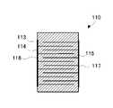
図3は、圧電素子110の正断面図である。圧電素子110は、印加電圧に対して変位を出力し、圧電層113、内部電極114、115および外部電極116、117を有している。圧電素子110は、圧電層113と内部電極114、115とが交互に積層されている。また、圧電素子110の側面において、外部電極116、117は内部電極114、115に接続されている。圧電層は、例えばPZT、チタン酸バリウム等の圧電材料で構成できる。電極材料には、Ag、Ag-Pd、Pt等を用いることができる。(Piezoelectric element)
FIG. 3 is a front sectional view of the
(伝達体)
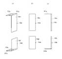
図4(a)~(c)は、それぞれ一対の伝達体150a、150bの斜視図、正面図および側面図である。一対の伝達体150a、150bは、圧電アクチュエータ本体105の変位を変位センサ155に伝達する。変位センサ155には一対の伝達体150a、150bを介して変位が伝達されるため、圧電素子110への変位拘束が発生しない。そのため、変位センサを直接貼り付けた場合の変位拘束による圧電素子の絶縁破壊を防止できる。また、特に、大変位タイプの圧電素子や高温下で使用される圧電素子では変位センサ等で圧電素子自身が拘束されることによるクラックが生じやすいが、圧電アクチュエータ100は、このようなクラックの発生を防止でき、信頼性を向上できる。(transmission body)
4(a) to (c) are a perspective view, a front view and a side view of a pair of
一対の伝達体150a、150bのそれぞれは、固着部151a、151bと本体部152a、152bとを備えている。固着部151a、151bは、圧電アクチュエータ本体105の互いに変位方向に離れた圧電素子同士の間の位置にそれぞれ固着される。本体部152a、152bは、固着部151a、151bから連続して形成され、圧電アクチュエータ本体105の表面に沿って設けられている。 Each of the pair of
図4に示すように、一対の伝達体150a、150bのそれぞれは、L字状の薄板で形成され、L字状の薄板の折れ曲がった先端部が固着部151a、151bとして圧電アクチュエータ本体105に固着していることが好ましい。この場合、L字状とは、変位方向に垂直な固着面と固着面から折れ曲がった面であって変位センサ155を取り付けられる均一な面があることを指す。このような先端部を用いることで十分な固着が可能になる。また、本体部152a、152bにおいて、固着部151a、151bから延びる二辺に沿った外周部を折り曲げることにより、折り曲げられた外周部が梁の役割を果たす補強部となり本体部の強度を上げ、共振周波数を向上させることもできる。 As shown in FIG. 4, each of the pair of
固着部151a、151bは、直近の圧電素子110の活性領域を変位方向へ投影した範囲(図4の例では、領域153a、153b)内で圧電アクチュエータ本体105と固着されていることが好ましい。これにより、不活性領域と活性領域との間で生じる応力を拘束せずに変位を検出できる。ここでいう活性領域とは、圧電素子110内に形成されている内部電極114、115が変位方向から見て重なる領域である。また不活性領域とは、圧電素子110内において活性領域を除いた領域である。 The fixed
固着部151a、151bは、連続する圧電素子110の両端面に固着されていることが好ましい。このように、複数の圧電素子に一対の伝達体150a、150bを跨がらせることで、圧電アクチュエータ本体105の全体の変位状況を反映した信号が得られる。これにより、圧電アクチュエータ本体105の全体に近い長さを対象に変位を検知できる。また、複数の圧電素子の変位量を変位センサにより測定することができ、変位センサが配置されていない圧電素子の数を減らすことができる。したがって、変位センサが配置されていない箇所の圧電素子の変位量の変化に起因した位置決め誤差を低減することができる。なお、検知に必要な変位量に応じ固着部151a、151b間の長さを調節することは可能である。一つの圧電素子110の両端面に固着部151a、151bを固着させることで、固着部の間の本体部の長さを最小限とし、変位センサの応答性を向上することができる。この場合でも、測定した変位量を圧電アクチュエータ本体が備える圧電素子の数で乗算することで、圧電アクチュエータ全体の変位量とすることができる。 The fixed
一対の伝達体150a、150bには、圧電アクチュエータ100の変位を正確に変位センサ155へ伝えるため、剛性が高く、圧電素子110の熱膨張に近い材料を用いるのが好ましい。例えば、ステンレスやインバーなどの金属、またはこれらとアルミナ、ジルコニアなどのセラミックス薄板を接合した部材が好適である。なお、伝達体150には、圧電素子と熱膨張率が近い材料を選択することにより、温度変化に起因する出力誤差を抑制できる。例えば、伝達体150の熱膨張係数と圧電素子110の熱膨張係数との差は、10×10-6/℃以下であることが好ましい。これにより、温度変化による圧電素子110と伝達体150との出力のずれを抑制できる。なお、精密に変位量を測定したい場合には、伝達体150および圧電素子110の熱膨張を測定し、変位量を補正してもよい。In order to accurately transmit the displacement of the
(変位センサ)
変位センサ155は、例えば、歪ゲージで構成され、両端が一対の伝達体150a、150bのそれぞれに取り付けられており、圧電アクチュエータ本体105の一部から伝達された変位を検知する。このように、変位センサ155は、一対の伝達体150a、150bを介して圧電アクチュエータ本体105に取り付けられているため、圧電素子への直接接着による応力集中や圧電素子の変位を拘束することが発生せず、高変位タイプ、高温タイプなど標準品より大きな変位を示す圧電アクチュエータでも良好な耐久性を維持することができる。(displacement sensor)
The
変位センサ155は、両端が一対の伝達体150a、150bのそれぞれの本体部152a、152bに取り付けられている。これにより、圧電素子110の変位を拘束せずに伝達体150a、150bを介して変位を検知できる。その結果、圧電素子の変位の拘束によるクラックで絶縁破壊するのを防止しつつ圧電アクチュエータを使用した位置決め誤差を低減できる。また、圧電アクチュエータ本体の表面に沿って設けられた本体部同士に跨って変位センサが配置されているので、圧電アクチュエータ100が伸びたときに変位センサ155も伸びることで、圧電アクチュエータ100の変位と変位センサ155の変位が同相の歪となり、制御性が向上する。 Both ends of the
変位センサ155は、変位センサ本体156、リード線157、158に接続され、リード線158が、センサ用端子159に接続されることで、検知された変位が伝達される。これにより、圧電アクチュエータ本体105の変位を確認して、正確にその変位を把握することができフィードバック制御により圧電アクチュエータを使用した精密な位置決めが可能になる。 The
(変位制御システム)
上記の圧電アクチュエータ100を用いて変位制御システム190を構成できる。図5は、変位制御システム190の概略図である。図5に示すように、変位制御システム190は、圧電アクチュエータ100、フィードバック制御装置170および駆動電源180を備えている。(Displacement control system)
A
変位センサ155のセンサ用の端子159は、フィードバック制御装置170に接続されている。検知された変位の信号は、フィードバック制御装置170に入力され、フィードバック制御装置170は、検知された信号を圧電アクチュエータ100の変位に変換し、検知された変位をもとに必要な駆動量を算出する。検知信号から変位への変換は、同相であり、変位センサ155から伸びの信号の入力があったときには、圧電アクチュエータ100の伸びの変位を出力する。フィードバック制御装置170は、算出された駆動量に応じて駆動電源180を制御し、駆動電源180は、フィードバック制御装置170から指令を受けた電圧を圧電アクチュエータ本体105に印加する。このようにして、誤差を低減した変位制御システム190を実現できる。
(圧電アクチュエータの製造方法)
次に、上記のように構成された圧電アクチュエータ100の製造方法を説明する。まず、圧電層と内部電極とが交互に積層された圧電素子110を作製する。具体的には、圧電セラミックスのグリーンシートにAgやAg-Pd等の電極ペーストを印刷して積層、圧着し、焼成する。次に、圧電素子110の側面に積層方向に沿って、内部電極に接続された外部電極116、117を形成する。圧電素子110の側面に電極ペーストを印刷して焼成することで外部電極116、117を形成できる。一方、あらかじめ本体部152a、152bの端部から折れ曲がった両先端部が固着部151a、151bになっている一対の伝達体150a、150bを準備しておく。(Manufacturing method of piezoelectric actuator)
Next, a method for manufacturing the
得られた複数の圧電素子110の積層方向の端面には、エポキシ等の接着剤を塗布して接着し、直列方向に連結する。その際に、変位をモニタリングしたい圧電素子110の両端面に一対の伝達体150a、150bを接着する。その際には、直近の圧電素子の活性領域の変位方向への投影領域のみ接着する。このようにして多連化を行い、接着剤を硬化させる。そして、金属製で板状のリード線を、外部電極に固着させて、多連化した圧電アクチュエータ本体105を作製できる。 An adhesive such as epoxy is applied to the end surfaces of the plurality of
上記の圧電アクチュエータ本体105を座140に設置し、キャップ160を被せて封止する。このとき、圧電アクチュエータ100のキャップ160の中に封止される圧電アクチュエータ本体105に、一対の伝達体150a、150bおよび変位センサ155を設け、圧電アクチュエータ本体105と一緒にキャップ160内に封止する。変位センサ155の端子および駆動用電極に接続されるリード線121、122、158は、座140に挿通された端子126、127、159に接続されている。このようにして、圧電アクチュエータ100を作製することができる。なお、駆動用の端子126、127は、それぞれ駆動電源180、センサ用の端子159は、フィードバック制御装置170に電気的に接続される。 The above piezoelectric actuator
[第2実施形態(伸縮型1)]
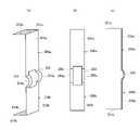
第1実施形態では、一対の伝達体150a、150bは分離して設けられているが、これらは連結されていてもよい。図6(a)、(b)は、それぞれ一対の伝達体250a、250bが連結された圧電アクチュエータ200を示す正断面図および側断面図である。図7(a)~(c)は、それぞれ伝達体250a、250bの斜視図、正面図および側面図である。[Second Embodiment (Extendable Type 1)]
Although the pair of
図6(a)、(b)、図7(a)~(c)に示すように、それぞれ伝達体250a、250bは、湾曲した連結体255、256により連結されている。並列して形成された湾曲した連結体255、256を有する伝達体250a、250bは、伸縮部付きの薄板とみなすこともできる。湾曲した連結体255、256は、一対の伝達体250a、250bの中心を結ぶ中心線に対して対称かつ圧電アクチュエータ本体105の変位方向に対して並列に設けられていることが好ましい。 As shown in FIGS. 6(a), (b), and FIGS. 7(a) to (c), the
これにより、一対の伝達体250a、250bの位置ずれを抑制し、一対の伝達体250a、250bの変位方向を圧電アクチュエータ本体105の変位方向に対して平行に維持できる。すなわち、薄板の本体部252a、252bの表面の平面度を維持できる。その結果、組み立てや測定精度の向上にもつながる。 As a result, positional deviation of the pair of
連結体255、256のそれぞれは、圧電アクチュエータ本体105の表面に平行な方向(連結体の同一平面内)に撓んだ湾曲部255a、256aを有し、湾曲部255a、256aは、変位方向に垂直な方向に変位センサ155の一部と重なる位置に設けられていることが好ましい。これにより、変位センサ155を伝達体250a、250bに取り付けた際に変位センサ155を連結部255、256の湾曲部255a、256aが支えることで、取付け時の時の変位センサ155の撓みを防止することができる。この結果、圧電アクチュエータ本体105の変位を正確に検出ことができる。さらに、連結体255、256と変位センサ155とは固着等により固定されていないので、圧電アクチュエータ本体105の変位に応じた変位センサ155の変形を妨げることなく、連結体255、256の変形を容易にし、圧電アクチュエータ本体105の変位を検出しやすくすることができる。このように、湾曲部255a、256aのようにバネ性の機構を有することで連結体255、256の同一平面内に伸縮機構が形成される。なお、連結体255、256の厚さよりも一対の伝達体250a、250bの厚さを薄く形成してもよい。これにより、連結体255、256の剛性を維持しつつ、伝達体250a、250bを軽量化することができ、変位センサの応答性を向上させることもできる。 Each of the connecting
[第3実施形態(伸縮型2)]
第2実施形態では、連結体255、256の湾曲部255a、256aが圧電アクチュエータ本体105の表面に平行な方向に撓んでいるが、圧電アクチュエータ本体105の表面に垂直な方向に撓んでいてもよい。図8(a)、(b)は、それぞれ湾曲部355a、356aが圧電アクチュエータ本体105の表面に垂直な方向(連結体の厚み方向)に撓んだ圧電アクチュエータ300を示す正断面図および側断面図である。図9(a)~(c)は、それぞれ伝達体350a、350bの斜視図、正面図および側面図である。[Third Embodiment (Extendable Type 2)]
In the second embodiment, the
図9(a)~(c)に示す例では、連結体355、356は、一対の伝達体350a、350bの中心を結ぶ中心線に対して対称かつ圧電アクチュエータ本体105の変位方向に対して並列に一対で設けられている。これにより、一対の伝達体350a、350bの位置ズレを抑制し、一対の伝達体350a、350bの変位方向を圧電アクチュエータ本体105の変位方向に対して平行に維持できる。すなわち、薄板の本体部352a、352bの表面の平面度を維持できる。その結果、組み立てや測定精度の向上にもつながる。 In the examples shown in FIGS. 9A to 9C, the connecting
連結体355、356のそれぞれは、圧電アクチュエータ本体105の表面に垂直な方向に撓んだ湾曲部355a、356aを有し、連結体355、356は、変位センサ155に重ならない位置に設けられていてもよい。これにより、変位センサ155の変形を妨げることなく、連結体355、356の変形を容易にし、一対の伝達体350a、350bの変位を検出しやすくすることができる。このように、湾曲部355a、356aのようにバネ性の機構を有することで連結体355、356の厚み方向に伸縮機構が形成される。なお、連結体355、356の厚さよりも一対の伝達体350a、350bの厚さを薄く形成してもよい。これにより、連結体355、356の剛性を維持しつつ、伝達体350a、350bを軽量化することができ、変位センサの応答性を向上させることもできる。 Each of the connecting
上述の形態において、伝達体250a、250b(350a、350b)と連結体255、256(355、356)とは、一体の形態を説明したが、伝達体250a、250b(350a、350b)と連結体255、256(355、356)とが、別部材で構成され、各部材を接合して形成してもよい。この場合も上記同様の効果を得ることができる。 In the above embodiment, the transmitting
更に、上記形態において、一対の連結体255、256(355、356)を用いる形態を説明したが、連結体1つまたは3つ以上の複数で構成されていても構わない。 Furthermore, in the above embodiment, a mode using a pair of connecting
また、上述の第1実施形態、第2実施形態及び第3実施形態における伝達体150a、150b、250a、250b、350a、350bの本体部152a、152b、252a、252b、352a、352bに対して、圧電アクチュエータ本体に組み込んだ際の変位方向と垂直な方向の両端を折曲げるリブ加工を行いリブ構造としたり、アルミナ、ジルコニアなどのセラミックス薄板を本体部152a、152b、252a、252b、352a、352bに接合して、前記変位方向と平行な方向に延在する補強部を備える構成としたりしてもよい。これにより、本体部152a、152b、252a、252b、352a、352bの面の剛性を向上させ、変位センサの応答性を向上させることも可能である。 In addition, for the
また、上述の第1実施形態、第2実施形態及び第3実施形態における伝達体150a、150b、250a、250b、350a、350bの本体部152a、152b、252a、252b、352a、352bに対して、打抜き加工を行い複数の貫通孔を有する形態としてもよい。これにより、本体部152a、152b、252a、252b、352a、352bの軽量化を行うことができ、変位センサの応答性を向上させることも可能である。 In addition, with respect to the
100、200、300 圧電アクチュエータ
105 圧電アクチュエータ本体
110 圧電素子
113 圧電層
114、115 内部電極
116、117 外部電極
121、122、157、158 リード線
126、127、159 端子
130 突起
140 座
150a、150b、250a、250b、350a、350b 伝達体
151a、151b 固着部
152a、152b、252a、252b、352a、352b 本体部
153a、153b 領域(活性領域を変位方向へ投影した範囲)
155 変位センサ
156 変位センサ本体
160 キャップ
170 フィードバック制御装置
180 駆動電源
190 変位制御システム
255、256、355、356 連結体
255a、256a、355a、356a 湾曲部100, 200, 300
155
Claims (12)
Translated fromJapanese複数の圧電素子を直列に連結して形成された圧電アクチュエータ本体と、
前記圧電アクチュエータ本体の互いに変位方向に離れた前記圧電素子同士の間の位置に固着される固着部を有し、前記固着部から連続し前記圧電アクチュエータ本体の表面に沿って設けられた本体部を有する一対の伝達体と、
前記一対の伝達体から伝達された前記圧電アクチュエータ本体の変位を検知する変位センサと、
前記圧電アクチュエータ本体の一端を固定する座と、
有底の筒状に形成され、内部に前記圧電アクチュエータ本体、前記一対の伝達体および前記変位センサを収容し、開口端が座に封止されたキャップと、を備え、
前記変位センサは、両端部が前記一対の伝達体のそれぞれの本体部に取り付けられていることを特徴とする圧電アクチュエータ。A piezoelectric actuator that is displaced by application of a voltage,
a piezoelectric actuator body formed by connecting a plurality of piezoelectric elements in series;
a main body having a fixing portion fixed to a position between the piezoelectric elements separated from each other in the displacement direction of the piezoelectric actuator main body, the main body being continuous from the fixing portion and provided along the surface of the piezoelectric actuator main body; a pair of transmitters having
a displacement sensor that detects the displacement of the piezoelectric actuator body transmitted from the pair of transmission bodies;
a seat for fixing one end of the piezoelectric actuator body;
a cap formed in a cylindrical shape with a bottom, housing the piezoelectric actuator main body, the pair of transmission bodies, and the displacement sensor therein, and having an open end sealed with a seat;
A piezoelectric actuator, wherein both ends of the displacement sensor are attached to respective body portions of the pair of transmission bodies.
前記L字状の薄板の折れ曲がった先端部が前記固着部として前記圧電アクチュエータ本体に固着していることを特徴とする請求項1記載の圧電アクチュエータ。Each of the pair of transmission bodies is formed of an L-shaped thin plate,
2. The piezoelectric actuator according to claim 1, wherein a bent tip portion of said L-shaped thin plate is fixed to said piezoelectric actuator main body as said fixing portion.
Priority Applications (1)
| Application Number | Priority Date | Filing Date | Title |
|---|---|---|---|
| JP2018163455AJP7109314B2 (en) | 2018-08-31 | 2018-08-31 | piezoelectric actuator |
Applications Claiming Priority (1)
| Application Number | Priority Date | Filing Date | Title |
|---|---|---|---|
| JP2018163455AJP7109314B2 (en) | 2018-08-31 | 2018-08-31 | piezoelectric actuator |
Publications (2)
| Publication Number | Publication Date |
|---|---|
| JP2020035973A JP2020035973A (en) | 2020-03-05 |
| JP7109314B2true JP7109314B2 (en) | 2022-07-29 |
Family
ID=69668727
Family Applications (1)
| Application Number | Title | Priority Date | Filing Date |
|---|---|---|---|
| JP2018163455AActiveJP7109314B2 (en) | 2018-08-31 | 2018-08-31 | piezoelectric actuator |
Country Status (1)
| Country | Link |
|---|---|
| JP (1) | JP7109314B2 (en) |
Citations (5)
| Publication number | Priority date | Publication date | Assignee | Title |
|---|---|---|---|---|
| US4958100A (en) | 1989-02-22 | 1990-09-18 | Massachusetts Institute Of Technology | Actuated truss system |
| JP2014072302A (en) | 2012-09-28 | 2014-04-21 | Taiheiyo Cement Corp | Multi-ganged element and manufacturing method therefor |
| JP2015012085A (en) | 2013-06-27 | 2015-01-19 | 太平洋セメント株式会社 | Piezoelectric actuator |
| JP2017098383A (en) | 2015-11-20 | 2017-06-01 | 日本特殊陶業株式会社 | Piezoelectric actuator |
| JP2017118040A (en) | 2015-12-25 | 2017-06-29 | 日本特殊陶業株式会社 | Piezoelectric actuator |
Family Cites Families (4)
| Publication number | Priority date | Publication date | Assignee | Title |
|---|---|---|---|---|
| JPS63283180A (en)* | 1987-05-15 | 1988-11-21 | Yokogawa Electric Corp | Piezoelectric actuator with displacement sensor |
| JPH04352480A (en)* | 1991-05-30 | 1992-12-07 | Nec Kansai Ltd | piezoelectric actuator |
| JPH05206536A (en)* | 1992-01-27 | 1993-08-13 | Nec Corp | Piezoelectric actuator |
| JP3130647B2 (en)* | 1992-06-04 | 2001-01-31 | 日立建機株式会社 | Fine movement mechanism |
- 2018
- 2018-08-31JPJP2018163455Apatent/JP7109314B2/enactiveActive
Patent Citations (5)
| Publication number | Priority date | Publication date | Assignee | Title |
|---|---|---|---|---|
| US4958100A (en) | 1989-02-22 | 1990-09-18 | Massachusetts Institute Of Technology | Actuated truss system |
| JP2014072302A (en) | 2012-09-28 | 2014-04-21 | Taiheiyo Cement Corp | Multi-ganged element and manufacturing method therefor |
| JP2015012085A (en) | 2013-06-27 | 2015-01-19 | 太平洋セメント株式会社 | Piezoelectric actuator |
| JP2017098383A (en) | 2015-11-20 | 2017-06-01 | 日本特殊陶業株式会社 | Piezoelectric actuator |
| JP2017118040A (en) | 2015-12-25 | 2017-06-29 | 日本特殊陶業株式会社 | Piezoelectric actuator |
Also Published As
| Publication number | Publication date |
|---|---|
| JP2020035973A (en) | 2020-03-05 |
Similar Documents
| Publication | Publication Date | Title |
|---|---|---|
| CN101603870B (en) | Diaphragm for pressure sensor and pressure sensor | |
| CN104956194B (en) | Pressure sensor, mass flow meter using the same, and mass flow controller | |
| TWI400437B (en) | Pressure sensor | |
| US7942062B2 (en) | Pressure sensor and method for manufacturing the same | |
| US8667849B2 (en) | Pressure sensor | |
| JP4756394B2 (en) | pressure sensor | |
| JP5459890B1 (en) | Force sensor | |
| JP2012093135A (en) | Pressure sensor | |
| JPH10282134A (en) | Peripherally provided sensor | |
| JP2013104753A (en) | Physical quantity detector | |
| JP7109314B2 (en) | piezoelectric actuator | |
| JP2021019051A (en) | Piezoelectric actuator and manufacturing method thereof | |
| JP7164864B2 (en) | piezoelectric actuator | |
| JP7164847B2 (en) | piezoelectric actuator | |
| EP3845881B1 (en) | Pressure meter | |
| EP2891872B1 (en) | Combustion pressure sensor | |
| JP7394870B2 (en) | piezoelectric actuator | |
| JP6673579B2 (en) | Actuator | |
| JP7463653B2 (en) | Piezoelectric Actuator | |
| JP2021019422A (en) | Piezoelectric actuator sealed type metal frame and piezoelectric actuator | |
| JP2023109209A (en) | piezoelectric actuator | |
| WO2012063477A1 (en) | Pressure sensor | |
| US20250049333A1 (en) | Pressure sensor | |
| JP2023070327A (en) | Metal housing for piezoelectric actuator and piezoelectric actuator | |
| JP2023055534A (en) | Pressure sensor element and pressure sensor |
Legal Events
| Date | Code | Title | Description |
|---|---|---|---|
| A621 | Written request for application examination | Free format text:JAPANESE INTERMEDIATE CODE: A621 Effective date:20210625 | |
| A977 | Report on retrieval | Free format text:JAPANESE INTERMEDIATE CODE: A971007 Effective date:20220630 | |
| TRDD | Decision of grant or rejection written | ||
| A01 | Written decision to grant a patent or to grant a registration (utility model) | Free format text:JAPANESE INTERMEDIATE CODE: A01 Effective date:20220705 | |
| A61 | First payment of annual fees (during grant procedure) | Free format text:JAPANESE INTERMEDIATE CODE: A61 Effective date:20220719 | |
| R150 | Certificate of patent or registration of utility model | Ref document number:7109314 Country of ref document:JP Free format text:JAPANESE INTERMEDIATE CODE: R150 | |
| R250 | Receipt of annual fees | Free format text:JAPANESE INTERMEDIATE CODE: R250 |