JP7106947B2 - Position detector - Google Patents
Position detectorDownload PDFInfo
- Publication number
- JP7106947B2 JP7106947B2JP2018071471AJP2018071471AJP7106947B2JP 7106947 B2JP7106947 B2JP 7106947B2JP 2018071471 AJP2018071471 AJP 2018071471AJP 2018071471 AJP2018071471 AJP 2018071471AJP 7106947 B2JP7106947 B2JP 7106947B2
- Authority
- JP
- Japan
- Prior art keywords
- mold resin
- groove
- wiring
- position detection
- component
- Prior art date
- Legal status (The legal status is an assumption and is not a legal conclusion. Google has not performed a legal analysis and makes no representation as to the accuracy of the status listed.)
- Active
Links
Images


Classifications
- G—PHYSICS
- G01—MEASURING; TESTING
- G01D—MEASURING NOT SPECIALLY ADAPTED FOR A SPECIFIC VARIABLE; ARRANGEMENTS FOR MEASURING TWO OR MORE VARIABLES NOT COVERED IN A SINGLE OTHER SUBCLASS; TARIFF METERING APPARATUS; MEASURING OR TESTING NOT OTHERWISE PROVIDED FOR
- G01D5/00—Mechanical means for transferring the output of a sensing member; Means for converting the output of a sensing member to another variable where the form or nature of the sensing member does not constrain the means for converting; Transducers not specially adapted for a specific variable
- G01D5/12—Mechanical means for transferring the output of a sensing member; Means for converting the output of a sensing member to another variable where the form or nature of the sensing member does not constrain the means for converting; Transducers not specially adapted for a specific variable using electric or magnetic means
- G01D5/14—Mechanical means for transferring the output of a sensing member; Means for converting the output of a sensing member to another variable where the form or nature of the sensing member does not constrain the means for converting; Transducers not specially adapted for a specific variable using electric or magnetic means influencing the magnitude of a current or voltage
- G01D5/142—Mechanical means for transferring the output of a sensing member; Means for converting the output of a sensing member to another variable where the form or nature of the sensing member does not constrain the means for converting; Transducers not specially adapted for a specific variable using electric or magnetic means influencing the magnitude of a current or voltage using Hall-effect devices
- G01D5/145—Mechanical means for transferring the output of a sensing member; Means for converting the output of a sensing member to another variable where the form or nature of the sensing member does not constrain the means for converting; Transducers not specially adapted for a specific variable using electric or magnetic means influencing the magnitude of a current or voltage using Hall-effect devices influenced by the relative movement between the Hall device and magnetic fields
- G—PHYSICS
- G01—MEASURING; TESTING
- G01B—MEASURING LENGTH, THICKNESS OR SIMILAR LINEAR DIMENSIONS; MEASURING ANGLES; MEASURING AREAS; MEASURING IRREGULARITIES OF SURFACES OR CONTOURS
- G01B7/00—Measuring arrangements characterised by the use of electric or magnetic techniques
- G01B7/003—Measuring arrangements characterised by the use of electric or magnetic techniques for measuring position, not involving coordinate determination
- G—PHYSICS
- G01—MEASURING; TESTING
- G01D—MEASURING NOT SPECIALLY ADAPTED FOR A SPECIFIC VARIABLE; ARRANGEMENTS FOR MEASURING TWO OR MORE VARIABLES NOT COVERED IN A SINGLE OTHER SUBCLASS; TARIFF METERING APPARATUS; MEASURING OR TESTING NOT OTHERWISE PROVIDED FOR
- G01D11/00—Component parts of measuring arrangements not specially adapted for a specific variable
- G01D11/24—Housings ; Casings for instruments
- G01D11/245—Housings for sensors
Landscapes
- Physics & Mathematics (AREA)
- General Physics & Mathematics (AREA)
- Transmission And Conversion Of Sensor Element Output (AREA)
- Measurement Of Length, Angles, Or The Like Using Electric Or Magnetic Means (AREA)
Description
Translated fromJapanese本開示は、位置検出装置に関する。 The present disclosure relates to a position detection device.
従来、車両等に用いられる電子制御スロットルが備えるスロットルバルブの回転角、アクセルペダルモジュールが備えるアクセルペダルの回転角、または、クラッチアクチュエータのストローク量等を検出する位置検出装置が知られている。また、特許文献1に記載されているように、磁気検出素子と配線とを1次モールドした1次成形品がターミナルに接続されており、1次成形品とターミナルとが2次モールドされている位置検出装置が知られている。 2. Description of the Related Art Conventionally, there is known a position detection device that detects the rotation angle of a throttle valve provided in an electronically controlled throttle used in a vehicle or the like, the rotation angle of an accelerator pedal provided in an accelerator pedal module, or the stroke amount of a clutch actuator. Further, as described in
特許文献1の構成では、1次成形品が2次成形品に固定されている。車両等に用いられる温度環境において、線膨張により位置検出装置の2次成形品が変形することがある。2次成形品が変形するとき、1次成形品が反り、1次成形品の位置がずれる。1次成形品の位置がずれたとき、位置検出装置が形成する磁気回路から磁気検出素子の位置がずれるため、位置検出装置による位置検出の精度が悪化する。 In the configuration of
本開示の目的は、位置検出の精度が向上する位置検出装置を提供することにある。 An object of the present disclosure is to provide a position detection device that improves the accuracy of position detection.
本発明の第1の態様の位置検出装置は、磁気検出素子(11、21)、配線(13、23)、2つの第1モールド樹脂(10、20)、2つのターミナル(60)および第2モールド樹脂(30)を備える。磁気検出素子は、磁界の変化を検出可能である。配線は、磁気検出素子に接続されている。第1モールド樹脂は、配線が露出するように、磁気検出素子および配線をモールドしている。ターミナルは、配線に接続されている。A position detecting device according toa first aspect of the present invention includes magnetic detecting elements (11, 21), wiring (13, 23),two first mold resins (10, 20),two terminals (60) and a second A mold resin (30) is provided. The magnetic sensing element is capable of detecting changes in the magnetic field. The wiring is connected to the magnetic detection element. The first mold resin molds the magnetic sensing element and the wiring so that the wiring is exposed. The terminal is connected to the wiring.
第2モールド樹脂は、磁気検出素子が位置する第1モールド樹脂が露出するように、第1モールド樹脂およびターミナルをモールドしており、変形抑制部(40)を有する。変形抑制部は、第2モールド樹脂が変形したとき、第1モールド樹脂の変形を抑制する。変形抑制部は、第2モールド樹脂の板厚方向に凹みつつ、第2モールド樹脂の長手方向に延びている溝部(41、42)である。第2モールド樹脂は、2つの第1モールド樹脂および2つのターミナルをモールドし、複数のウェルドライン(51、52、53)およびウェルドラインが交差する点である合流点(54)をさらに有する。溝部は、ターミナル側の第1モールド樹脂の底面(105、205)から合流点までの距離(Dc1、Dc2)が第1モールド樹脂の底面から溝部の底面である溝部底面(415、425)までの距離(Dg1、Dg2)よりも大きくなるように、形成されている。The second mold resin molds the first mold resin and the terminals so that the first mold resin on which the magnetic sensing element is located is exposed, and has a deformation suppressing portion (40). The deformation suppressing portion suppresses deformation of the first mold resin when the second mold resin is deformed. The deformation suppressing portions are grooves (41, 42) extending in the longitudinal direction of the second mold resin while being recessed in the plate thickness direction of the second mold resin.The second mold resin molds the two first mold resins and the two terminals, and further has a plurality of weld lines (51, 52, 53) and a junction (54) where the weld lines intersect. In the groove, the distance (Dc1, Dc2) from the bottom surface (105, 205) of the first mold resin on the terminal side to the junction is the distance from the bottom surface of the first mold resin to the groove bottom surface (415, 425), which is the bottom surface of the groove. It is formed so as to be larger than the distance (Dg1, Dg2).
この構成により、第1モールド樹脂の反りが抑制され、第1モールド樹脂のずれが抑制される。このため、磁気検出素子の位置ずれが抑制される。したがって、位置検出装置の位置検出の精度が向上する。 With this configuration, warping of the first mold resin is suppressed, and displacement of the first mold resin is suppressed. Therefore, displacement of the magnetic sensing element is suppressed. Therefore, the position detection accuracy of the position detection device is improved.
以下、位置検出装置の実施形態を図面に基づいて説明する。複数の実施形態の説明において、実質的に同一の構成には、同一の符号を付して説明する。本実施形態という場合、複数の実施形態を包括する。本実施形態による位置検出装置は、例えば、車両のエンジンの気筒内に吸入される空気量を制御する電子制御スロットル81に用いられる。まず、電子制御スロットル81について、説明する。 Hereinafter, embodiments of the position detection device will be described based on the drawings. In the description of a plurality of embodiments, substantially the same configurations are denoted by the same reference numerals. The term "this embodiment" encompasses a plurality of embodiments. The position detection device according to this embodiment is used, for example, in an electronically controlled
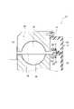
図1に示すように、電子制御スロットル81は、ハウジング83、吸気通路84、スロットルバルブ85、バルブシャフト86、モータ87、ホルダ88および磁石89を備える。ハウジング83には、エンジンに空気を導入する吸気通路84が形成されている。スロットルバルブ85は、円板状に形成されており、吸気通路84内に設けられている。 As shown in FIG. 1, the electronically controlled
バルブシャフト86は、スロットルバルブ85に固定されている。バルブシャフト86の両端は、ハウジング83に対して回転可能にモータ87およびホルダ88に接続されている。これにより、スロットルバルブ85は、バルブシャフト86の中心を回転軸として回転可能である。モータ87は、バルブシャフト86の一端に接続されている。図示しないエンジンの電子制御装置(ECU)の指令によって、モータ87は、駆動制御される。モータ87の駆動により、スロットルバルブ85の開度が制御され、エンジンに供給される吸気量が調節される。 A
ホルダ88は、有底筒状に形成されており、バルブシャフト86の他端に設けられている。ホルダ88の内壁には、磁気発生手段としての2個の磁石89、および、この2個の磁石89を周方向に接続する図示しない2個のヨークが設けられている。2個の磁石89は、スロットルバルブ85の回転軸に対して径方向に向き合うように設けられている。2個の磁石89は、一方のヨークにN極の磁束を与え、他方のヨークにS極の磁束を与える。ホルダ88の内側を一方のヨークから他方のヨークに磁束が流れることで、スロットルバルブ85の回転軸に対し垂直方向に磁束が流れる磁界が生じる。スロットルバルブ85が回転するとき、ホルダ88の内側の磁界の向きが変化する。ハウジング83のホルダ側に位置検出装置1が設けられている。 The
(第1実施形態)
位置検出装置1は、第2モールド樹脂としてのセンサカバー30、第1モールド樹脂としての第1部品10、第2部品20および2つのターミナル60を備える。(First embodiment)
The
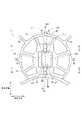
図2に示すように、センサカバー30は、皿状または板状に樹脂で形成されており、ねじ31等によりハウジング83に固定されている。センサカバー30は、第1磁気検出素子11が位置する第1部品10が露出するように、かつ、第2磁気検出素子21が位置する第2部品20が露出するように、第1部品10、第2部品20およびターミナル60を一体にモールドしている。 As shown in FIG. 2, the
また、センサカバー30は、第1部品10および第2部品20を支持するとともに、複数のリブ32を有する。複数のリブ32により、センサカバー30の剛性が向上する。以下、センサカバー30の長手方向を単に、長手方向と記載する。センサカバー30の短手方向を単に、短手方向と記載する。センサカバー30の板厚方向を単に、板厚方向と記載する。 Moreover, the
図3に示すように、第1部品10は、磁気検出素子としての第1磁気検出素子11、第1リード線12、第1配線13、第1樹脂部14および第1凸部15を有する。第1部品10は、第1配線13が露出するように、第1磁気検出素子11、第1リード線12および第1配線13を樹脂でモールドしている。 As shown in FIG. 3 , the
第1磁気検出素子11は、ホール素子であり、信号増幅回路と一体化している。第1磁気検出素子11は、磁界の変化を検出可能である。スロットルバルブ85が回転するとき、第1磁気検出素子11は、ホルダ88の内側の磁界の変化を検出する。 The first
第1リード線12は、第1磁気検出素子11に接続されており、第1配線13と溶接により接続されている。第1配線13は、第1リード線12とは反対側の第1配線13の端部が第1樹脂部14から露出するように、設けられている。第1凸部15は、第2部品20と接触する面に形成されており、第2凹部25に向かって突出している。また、第1凸部15は、先端に向かって外径が小さくなるように、テーパ形状に形成されている。 The
第2部品20は、第1部品10と同様に形成されており、磁気検出素子としての第2磁気検出素子21、第2リード線22、第2配線23、第2樹脂部24および第2凹部25を有する。第2部品20は、第1部品10と同様に、第2配線23が露出するように、第2磁気検出素子21、第2リード線22および第2配線23を樹脂でモールドしている。 The
第2磁気検出素子21は、第1磁気検出素子11と同様に、ホール素子であり、信号増幅回路と一体化している。第2磁気検出素子21は、磁界の変化を検出可能である。スロットルバルブ85が回転するとき、第2磁気検出素子21は、ホルダ88の内側の磁界の変化を検出する。 The second
第2リード線22は、第2磁気検出素子21に接続されており、第2配線23と溶接により接続されている。第2配線23は、第2リード線22とは反対側の第2配線23の端部が第2樹脂部24から露出するように、設けられている。第2凹部25は、第1部品10と接触する面に形成されており、第1凸部15に対応して凹んでいる。第1凸部15と第2凹部25とが嵌合し、第1部品10および第2部品20とが嵌合する。 The
ターミナル60は、第1リード線12とは反対側の第1配線13および第2リード線22とは反対側の第2配線23にそれぞれ接続されている。第1部品10および第2部品20は、ホルダ88の内側の磁界内に設けられている。第1部品10および第2部品20は、ホルダ88内の磁界の向きに応じて、第1部品10および第2部品20を通過する磁束密度に応じた電圧信号を出力する。この電圧信号は、センサカバー30にモールドされたターミナル60を通じてECUに伝送される。ECUは、車両の各部を制御する。 The terminal 60 is connected to the
図12に示すように、比較例の位置検出装置90では、磁気検出素子を有する1次成形品91は、2次成形品92に固定されている。車両等に用いられる温度環境において、線膨張により、2次成形品92が変形することがある。2次成形品92が変形するとき、1次成形品91が反り、1次成形品91の位置がずれる。1次成形品91の位置がずれたとき、位置検出装置90が形成する磁気回路から磁気検出素子の位置がずれるため、位置検出装置90による位置検出の精度が悪化する。そこで、本実施形態の位置検出装置1では、位置検出の精度が向上する。 As shown in FIG. 12 , in the
図4に示すように、センサカバー30は、段差部33、変形抑制部40、ウェルドラインとしての第1ウェルドライン51、第2ウェルドライン52および第3ウェルドライン53をさらに有する。 As shown in FIG. 4, the
長手方向に延びており、最も外側の第1部品10の一端面を第1端面101とする。第1端面101を通り、長手方向に延びている直線を第1直線L1とする。長手方向に延びており、最も外側の第2部品20の一端面を第2端面202とする。なお、第2端面202は、第1端面101とは反対側に設けられている。第2端面202を通り、長手方向に延びている直線を第2直線L2とする。図において、第1直線L1および第2直線L2を二点鎖線で記載している。 One end surface of the outermost
第1端面101に隣接する第1部品10の一側面を第1側面111とする。第1側面111とは反対側の第1部品10の側面を第2側面112とする。第2端面202に隣接する第2部品20の一側面を第3側面213とする。第3側面213とは反対側の第2部品20の側面を第4側面214とする。なお、第1側面111は、第3側面213に隣接する。第2側面112は、第4側面214に隣接する。 One side surface of the
段差部33は、第1直線L1および第2直線L2が通過する位置に、形成されている。段差部33は、センサカバー30の板厚が大きくまたは小さくなるように、凸形状または凹形状であり、複数形成されている。 The stepped
段差部33は、第1側面111または第3側面213側に、1つ形成されている。第1側面111または第3側面213側の段差部33は、センサカバー30の板厚が大きくなるように、形成されている。また、段差部33は、第2側面112または第4側面214側に、1つ形成されている。第2側面112または第4側面214側の段差部33は、センサカバー30の板厚が小さくなるように、形成されている。 One stepped
変形抑制部40は、センサカバー30が変形したとき、第1部品10または第2部品20の変形を抑制する。また、変形抑制部40は、第1溝部41および第2溝部42を含む。第1溝部41は、第1側面111または第3側面213側に、1つ形成されている。第2溝部42は、第2側面112または第4側面214側に、1つ形成されている。 The
第1溝部41および第2溝部42は、板厚方向に凹みつつ、長手方向に延びている。また、第1溝部41は、第1側面111または第3側面213から段差部33まで、長手方向に延びている。第2溝部42は、第2側面112または第4側面214から段差部33まで、長手方向に延びている。 The
さらに、第1溝部41および第2溝部42は、第1直線L1および第2直線L2の間に形成されている。なお、第1溝部41および第2溝部42の外縁は、第1直線L1または第2直線L2上に位置してもよい。また、第1溝部41は、第1側面111または第3側面213に対向する第1対向面411を含む。第2溝部42は、第2側面112または第4側面214に対向する第2対向面421を含む。 Further, the
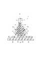
図5に示すように、第1溝部41は、第1溝部41の底面である第1溝部底面415を含む。第1溝部底面415は、第1対向面411と隣接する。また、第1溝部41は、板厚方向における断面において、第1溝部底面415の第1角部416の外縁が湾曲するように、形成されている。 As shown in FIG. 5 , the
図6に示すように、第2溝部42は、第2溝部42の底面である第2溝部底面425を含む。第2溝部底面425は、第2対向面421と隣接する。また、第2溝部42は、板厚方向における断面において、第2溝部底面425の第2角部426の外縁が湾曲するように、形成されている。図5および図6において、各部位を明確にするため、センサカバー30の断面の斜線ハッチングを省略する。 As shown in FIG. 6 , the
図5および図6に示すように、ターミナル60側の第1部品10の端面を第1部品底面105とする。第1部品底面105は、第1端面101、第1側面111および第2側面112に隣接する。ターミナル60側の第2部品20の端面を第2部品底面205とする。第2部品底面205は、第2端面202、第3側面213および第4側面214に隣接する。第1部品底面105は、第2部品底面205に隣接する。短手方向における第1部品10および第2部品20の最大長さを部品幅Dpとする。 As shown in FIGS. 5 and 6 , the end surface of the
第1ウェルドライン51、第2ウェルドライン52および第3ウェルドライン53は、センサカバー30が樹脂成形されたとき、溶融樹脂が合流したときに生じた線である。本実施形態では、短手方向の2方向および板厚方向の1方向に溶融樹脂が流れて、合流する。第1ウェルドライン51、第2ウェルドライン52および第3ウェルドライン53が交差する点を合流点54とする。図において、第1ウェルドライン51、第2ウェルドライン52および第3ウェルドライン53の位置を二点鎖線で記載している。また、図において、合流点54の位置を黒丸で記載している。 The
第1ウェルドライン51は、合流点54から板厚方向に延びている。第2ウェルドライン52は、第1部品10側に形成されており、合流点54からターミナル60側の第1部品10の角に向かって延びている。第3ウェルドライン53は、第2部品20側に形成されており、合流点54からターミナル60側の第2部品20の角に向かって延びている。 The
第1部品底面105または第2部品底面205から第1溝部底面415までの距離を第1溝部距離Dg1とする。第1部品底面105または第2部品底面205から合流点54までの距離を第1合流距離Dc1とする。第1合流距離Dc1は、部品幅Dpと等しい、すなわち、Dc1=Dp である。本明細書中、「等しい」は、常識的な誤差範囲を含むものとする。第1溝部41は、第1合流距離Dc1が第1溝部距離Dg1よりも大きくなるように、すなわち、Dc1>Dg1 となるように、形成されている。 The distance from the first
第1溝部41と同様に、第1部品底面105または第2部品底面205から第2溝部底面425までの距離を第2溝部距離Dg2とする。第1部品底面105または第2部品底面205から合流点54までの距離を第2合流距離Dc2とする。第2合流距離Dc2は、部品幅Dpおよび第1合流距離Dc1に等しい、すなわち、Dc1=Dc2=Dp である。第2溝部42は、第2合流距離Dc2が第2溝部距離Dg2よりも大きくなるように、すなわち、Dc2>Dg2 となるように、形成されている。 Similarly to the
[1]センサカバー30が変形したとき、第1部品10または第2部品20の変形が抑制される。これにより、第1部品10および第2部品20の反りが抑制され、第1部品10および第2部品20のずれが抑制される。このため、第1磁気検出素子11および第2磁気検出素子21の位置ずれが抑制される。したがって、位置検出装置1の位置検出の精度が向上する。[1] When the
[2]変形抑制部40は、第1溝部41および第2溝部42を有する。第1溝部41および第2溝部42により、製造に使用される樹脂量が抑制されつつ、第1部品10および第2部品20の周囲のセンサカバー30に樹脂を盛ることができる。センサカバー30に樹脂を盛ることで、センサカバー30の剛性が高くなる。このため、センサカバー30が変形しにくくなり、第1部品10および第2部品20のずれがさらに抑制される。したがって、第1磁気検出素子11および第2磁気検出素子21の位置ずれが抑制され、位置検出装置1の位置検出の精度がさらに向上する。[2] The
[3]第1溝部41は、第1合流距離Dc1が第1溝部距離Dg1よりも大きくなるように、形成されている。第2溝部42は、第2合流距離Dc2が第2溝部距離Dg2よりも大きくなるように、形成されている。これにより、センサカバー30を樹脂成形するとき、溶融樹脂が合流する時間が短くなり、溶融樹脂の温度が高い状態で、溶融樹脂が合流する。このため、センサカバー30のウェルド部分の強度が向上する。センサカバー30の強度が向上し、センサカバー30の剛性も向上する。このため、第1磁気検出素子11および第2磁気検出素子21の位置ずれが抑制されやすくなり、位置検出装置1の位置検出の精度がさらに向上する。[3] The
[4]第1溝部41は、板厚方向における断面において、第1角部416の外縁が湾曲するように、形成されている。第2溝部42は、板厚方向における断面において、第2角部426の外縁が湾曲するように、形成されている。これにより、センサカバー30が変形したとき、第1溝部41および第2溝部42の応力が分散される。応力が分散され、センサカバー30が変形しにくくなる。第1磁気検出素子11および第2磁気検出素子21の位置ずれが抑制されやすくなり、位置検出装置1の位置検出の精度がさらに向上する。[4] The
(第2実施形態)
第2実施形態では、変形抑制部の形状が異なる点を除き、第1実施形態と同様である。第2実施形態の位置検出装置2は、第2部品20を備えず、第1部品10を備える。第1端面101とは反対側の第1部品10の他端面を第3端面103とする。第2ウェルドライン52は、第1端面101側に形成されており、合流点54からターミナル60側の第1部品10の一方の角に向かって延びている。第3ウェルドライン53は、第3端面103側に形成されており、合流点54からターミナル60側の第1部品10の他方の角に向かって延びている。(Second embodiment)
The second embodiment is the same as the first embodiment except that the shape of the deformation suppressing portion is different. The
図7および図8に示すように、変形抑制部240は、第1溝部241および第2溝部242を有する。第1合流距離Dc1が部品幅Dpの半分となるように、すなわち、Dc1=Dp/2 となるように、第1部品10およびセンサカバー30は、調整されている。また、第2合流距離Dc2が部品幅Dpの半分となるように、すなわち、Dc2=Dp/2 となるように、第1部品10およびセンサカバー30は、調整されている。 As shown in FIGS. 7 and 8 , the
第1溝部241は、第1合流距離Dc1が第1溝部距離Dg1よりも大きくなるように、すなわち、Dp/2>Dg1 となるように、形成されている。第2溝部242は、第2合流距離Dc2が第2溝部距離Dg2よりも大きくなるように、すなわち、Dp/2>Dg2 となるように、形成されている。第2実施形態においても、第1実施形態と同様の効果を奏する。 The
(他の実施形態)
[i]本実施形態の位置検出装置は、アクセルペダルモジュールが備えるアクセルペダルの回転角度を検出するのに用いられてもよい。また、本実施形態の位置検出装置は、タンプルコントロールバルブの回転角度を検出するのに用いられてもよい。さらに、本実施形態の位置検出装置は、クラッチアクチュエータのストローク量を検出するのに用いられてもよい。(Other embodiments)
[i] The position detection device of this embodiment may be used to detect the rotation angle of the accelerator pedal provided in the accelerator pedal module. Also, the position detection device of this embodiment may be used to detect the rotation angle of the tumble control valve. Furthermore, the position detection device of this embodiment may be used to detect the stroke amount of the clutch actuator.
[ii]第1磁気検出素子11および第2磁気検出素子21は、ホール素子に限定されず、MR素子等であってもよい。なお、MRは、Magneto Resistiveの略である。[ii] The first
[iii]図9に示すように、第1実施形態の位置検出装置1は、第2部品20を備えず、1つの第1部品10により、構成されてもよい。第1直線L1は、第1端面101上に、設定される。第2直線L2は、第1端面101とは反対側の第3端面103上に、設定される。第1溝部41および第2溝部42は、第1直線L1および第2直線L2の間となるように、形成されている。同様に、本実施形態の位置検出装置1は、第1部品10を備えず、1つの第2部品20により、構成されてもよい。[iii] As shown in FIG. 9 , the
[iv]第2実施形態の位置検出装置2は、第1部品10を備えず、第2部品20を備えてもよい。[iv] The
[v]図10に示すように、本実施形態の位置検出装置1における変形抑制部40の第1溝部41および第2溝部42は、第1部品10および第2部品20と離間していてもよい。このとき、第1溝部41は、第1対向面411に対向する第3対向面413を含む。第2溝部42は、第2対向面421に対向する第4対向面424を含む。なお、第3対向面413は、第1溝部底面415に向かって第1溝部41が小さくなるように、傾斜している。同様に、第4対向面424は、第2溝部底面425に向かって第2溝部42が小さくなるように、傾斜している。[v] As shown in FIG. 10, the
[vi]図11に示すように、変形抑制部40は、複数の第1溝部41および第2溝部42を有してもよい。
以上、本開示はこのような実施形態に限定されるものではなく、その趣旨を逸脱しない範囲において、種々の形態で実施することができる。[vi] As shown in FIG. 11 , the
As described above, the present disclosure is not limited to such embodiments, and can be embodied in various forms without departing from the scope of the present disclosure.
1、2 ・・・位置検出装置、
10 ・・・第1部品(第1モールド樹脂)、
11 ・・・第1磁気検出素子、 13 ・・・第1配線、
20 ・・・第2部品(第1モールド樹脂)、
21 ・・・第2磁気検出素子、 23 ・・・第2配線、
30 ・・・センサカバー(第2モールド樹脂)
40、240 ・・・変形抑制部、
41、241 ・・・第1溝部、 42、242 ・・・第2溝部、
60 ・・・ターミナル。1, 2 ... position detection device,
10 ... first part (first mold resin),
11... First magnetic detecting element, 13... First wiring,
20 ... second part (first mold resin),
21 ... second magnetic detection element, 23 ... second wiring,
30 ... sensor cover (second mold resin)
40, 240 ... deformation suppressing portion,
41, 241 ... first groove, 42, 242 ... second groove,
60 Terminal.
Claims (6)
Translated fromJapanese前記磁気検出素子に接続されている配線(13、23)と、
前記配線が露出するように、前記磁気検出素子および前記配線をモールドしている2つの第1モールド樹脂(10、20)と、
前記配線に接続されている2つのターミナル(60)と、
前記磁気検出素子が位置する前記第1モールド樹脂が露出するように、前記第1モールド樹脂および前記ターミナルをモールドしており、変形したとき、前記第1モールド樹脂の変形を抑制する変形抑制部(40)を有する第2モールド樹脂(30)と、
を備え、
前記変形抑制部は、前記第2モールド樹脂の板厚方向に凹みつつ、前記第2モールド樹脂の長手方向に延びている溝部(41、42)であり、
前記第2モールド樹脂は、2つの前記第1モールド樹脂および2つの前記ターミナルをモールドし、複数のウェルドライン(51、52、53)および前記ウェルドラインが交差する点である合流点(54)をさらに有し、
前記溝部は、前記ターミナル側の前記第1モールド樹脂の底面(105、205)から前記合流点までの距離(Dc1、Dc2)が前記第1モールド樹脂の底面から前記溝部の底面である溝部底面(415、425)までの距離(Dg1、Dg2)よりも大きくなるように、形成されている位置検出装置。 a magnetic detection element (11, 21) capable of detecting a change in magnetic field;
wiring (13, 23) connected to the magnetic sensing element;
The magnetic sensing element and the wiring are molded such that the wiring is exposed.twoa first mold resin (10, 20);
connected to said wiringtwoa terminal (60);
A deformation suppressing portion ( 40), a second mold compound (30) having
with
The deformation suppressing portion is a groove portion (41, 42) extending in the longitudinal direction of the second mold resin while being recessed in the plate thickness direction of the second mold resin,
The second mold resin molds the two first mold resins and the two terminals, and forms a plurality of weld lines (51, 52, 53) and a junction (54) at which the weld lines intersect. further have
In the groove portion, the distance (Dc1, Dc2) from the bottom surface (105, 205) of the first mold resin on the terminal side to the confluence point is from the bottom surface of the first mold resin to the bottom surface of the groove portion ( 415, 425) is formed to be greater than the distance (Dg1, Dg2) toPosition detection device.
前記磁気検出素子に接続されている配線(13)と、
前記配線が露出するように、前記磁気検出素子および前記配線をモールドしている1つの第1モールド樹脂(10)と、
前記配線に接続されている1つのターミナル(60)と、
前記磁気検出素子が位置する前記第1モールド樹脂が露出するように、前記第1モールド樹脂および前記ターミナルをモールドしており、変形したとき、前記第1モールド樹脂の変形を抑制する変形抑制部(240)を有する第2モールド樹脂(30)と、
を備え、
前記変形抑制部は、前記第2モールド樹脂の板厚方向に凹みつつ、前記第2モールド樹脂の長手方向に延びている溝部(241、242)であり、
前記第2モールド樹脂は、前記第1モールド樹脂および前記ターミナルをモールドし、複数のウェルドライン(51、52、53)および前記ウェルドラインが交差する点である合流点(54)をさらに有し、
前記溝部は、前記第2モールド樹脂の短手方向における前記第1モールド樹脂の最大長さ(Dp)の半分が前記第1モールド樹脂の底面から前記溝部の底面である溝部底面(415、425)までの距離(Dg1、Dg2)よりも大きくなるように、形成されている位置検出装置。 a magnetic detection element (11) capable of detecting a change in magnetic field;
a wiring (13) connected to the magnetic sensing element;
The magnetic sensing element and the wiring are molded such that the wiring is exposed.onea first mold resin (10);
connected to the wiringonea terminal (60);
A deformation suppressing portion ( 240) with a second mold compound (30);
with
The deformation suppressing portion is a groove portion (241, 242) extending in the longitudinal direction of the second mold resin while being recessed in the plate thickness direction of the second mold resin,
The second mold resin molds the first mold resin and the terminals, and further has a plurality of weld lines (51, 52, 53) and a junction (54) at which the weld lines intersect,
In the groove, half of the maximum length (Dp) of the first mold resin in the lateral direction of the second mold resin extends from the bottom surface of the first mold resin to the bottom surface of the groove (415, 425). is formed to be greater than the distance (Dg1, Dg2) toPosition detection device.
前記変形抑制部は、前記第1直線および前記第2直線の間に形成されている請求項1から3のいずれか一項に記載の位置検出装置。 The position detection device according to any one of claims 1 to 3, wherein the deformation suppressing portion is formed between the first straight line and the second straight line.
前記溝部は、前記第1モールド樹脂の側面から前記段差部まで、前記第2モールド樹脂の長手方向に延びている請求項5に記載の位置検出装置。The second mold resin further has a stepped portion (33) formed to increase or decrease the plate thickness of the second mold resin,
6. The position detection device according to claim5 , wherein the groove extends in the longitudinal direction of the second mold resin from the side surface of the first mold resin to the stepped portion.
Priority Applications (5)
| Application Number | Priority Date | Filing Date | Title |
|---|---|---|---|
| JP2018071471AJP7106947B2 (en) | 2018-04-03 | 2018-04-03 | Position detector |
| CN201980022925.7ACN111971530B (en) | 2018-04-03 | 2019-03-19 | Position detecting device |
| DE112019001789.6TDE112019001789T5 (en) | 2018-04-03 | 2019-03-19 | Position detection device |
| PCT/JP2019/011424WO2019193968A1 (en) | 2018-04-03 | 2019-03-19 | Position detection device |
| US17/038,570US11385042B2 (en) | 2018-04-03 | 2020-09-30 | Position detection device |
Applications Claiming Priority (1)
| Application Number | Priority Date | Filing Date | Title |
|---|---|---|---|
| JP2018071471AJP7106947B2 (en) | 2018-04-03 | 2018-04-03 | Position detector |
Publications (3)
| Publication Number | Publication Date |
|---|---|
| JP2019184272A JP2019184272A (en) | 2019-10-24 |
| JP2019184272A5 JP2019184272A5 (en) | 2020-04-02 |
| JP7106947B2true JP7106947B2 (en) | 2022-07-27 |
Family
ID=68100512
Family Applications (1)
| Application Number | Title | Priority Date | Filing Date |
|---|---|---|---|
| JP2018071471AActiveJP7106947B2 (en) | 2018-04-03 | 2018-04-03 | Position detector |
Country Status (5)
| Country | Link |
|---|---|
| US (1) | US11385042B2 (en) |
| JP (1) | JP7106947B2 (en) |
| CN (1) | CN111971530B (en) |
| DE (1) | DE112019001789T5 (en) |
| WO (1) | WO2019193968A1 (en) |
Families Citing this family (1)
| Publication number | Priority date | Publication date | Assignee | Title |
|---|---|---|---|---|
| WO2022024961A1 (en)* | 2020-07-27 | 2022-02-03 | 日本精機株式会社 | Position detection device |
Citations (6)
| Publication number | Priority date | Publication date | Assignee | Title |
|---|---|---|---|---|
| JP2006275200A (en) | 2005-03-30 | 2006-10-12 | Jtekt Corp | Cover for rolling bearing device and rolling bearing device using the same |
| JP2006342758A (en) | 2005-06-10 | 2006-12-21 | Mikuni Corp | Sensor unit |
| JP2011182630A (en) | 2010-02-05 | 2011-09-15 | Denso Corp | Power conversion apparatus |
| JP2015121459A (en) | 2013-12-24 | 2015-07-02 | 株式会社デンソー | Position detector |
| WO2015145841A1 (en) | 2014-03-24 | 2015-10-01 | アイシン精機株式会社 | Rotation detection sensor and resin molding die for same |
| WO2016203735A1 (en) | 2015-06-18 | 2016-12-22 | 株式会社デンソー | Electric actuator |
Family Cites Families (14)
| Publication number | Priority date | Publication date | Assignee | Title |
|---|---|---|---|---|
| US5556541A (en)* | 1994-04-26 | 1996-09-17 | Filtertek, Inc. | Process for making hermetically sealed filter units and filters made thereby |
| US6448762B1 (en)* | 1999-11-01 | 2002-09-10 | Denso Corporation | Rotation-angle-detection device having magnetic sensor fixed to cover with detection direction transverse to cover longitudinal direction |
| CA2536190A1 (en) | 2005-02-21 | 2006-08-21 | Jtekt Corporation | Roller bearing apparatus, method of producing roller bearing apparatus and cover attached to roller bearing apparatus |
| JP4710047B2 (en)* | 2005-10-14 | 2011-06-29 | 康雄 飯島 | Variable reluctance angle detector |
| JP2008256600A (en)* | 2007-04-06 | 2008-10-23 | Jtekt Corp | Rotational speed detection device and rolling bearing device using the same |
| JP5330930B2 (en)* | 2008-09-05 | 2013-10-30 | 日本電産サンキョー株式会社 | Magnetic rotation detection device and manufacturing method thereof |
| US8635986B2 (en)* | 2009-10-26 | 2014-01-28 | Aisan Kogyo Kabushiki Kaisha | Rotation angle sensors |
| JP2011102770A (en)* | 2009-11-11 | 2011-05-26 | Aisan Industry Co Ltd | Rotation angle detector and throttle controller |
| JP5517083B2 (en)* | 2011-04-22 | 2014-06-11 | 株式会社デンソー | Rotation angle sensor |
| JP5626298B2 (en)* | 2012-09-18 | 2014-11-19 | 株式会社デンソー | Position detection device |
| JP6160549B2 (en)* | 2013-08-28 | 2017-07-12 | 株式会社デンソー | Position detection device |
| US9944002B2 (en) | 2013-08-28 | 2018-04-17 | Denso Corporation | Position detector apparatus |
| JP6359342B2 (en)* | 2014-05-29 | 2018-07-18 | 愛三工業株式会社 | Rotation angle detection sensor |
| JP2017083361A (en)* | 2015-10-30 | 2017-05-18 | 日立オートモティブシステムズ株式会社 | Inertial force sensor |
- 2018
- 2018-04-03JPJP2018071471Apatent/JP7106947B2/enactiveActive
- 2019
- 2019-03-19DEDE112019001789.6Tpatent/DE112019001789T5/enactivePending
- 2019-03-19WOPCT/JP2019/011424patent/WO2019193968A1/ennot_activeCeased
- 2019-03-19CNCN201980022925.7Apatent/CN111971530B/enactiveActive
- 2020
- 2020-09-30USUS17/038,570patent/US11385042B2/enactiveActive
Patent Citations (6)
| Publication number | Priority date | Publication date | Assignee | Title |
|---|---|---|---|---|
| JP2006275200A (en) | 2005-03-30 | 2006-10-12 | Jtekt Corp | Cover for rolling bearing device and rolling bearing device using the same |
| JP2006342758A (en) | 2005-06-10 | 2006-12-21 | Mikuni Corp | Sensor unit |
| JP2011182630A (en) | 2010-02-05 | 2011-09-15 | Denso Corp | Power conversion apparatus |
| JP2015121459A (en) | 2013-12-24 | 2015-07-02 | 株式会社デンソー | Position detector |
| WO2015145841A1 (en) | 2014-03-24 | 2015-10-01 | アイシン精機株式会社 | Rotation detection sensor and resin molding die for same |
| WO2016203735A1 (en) | 2015-06-18 | 2016-12-22 | 株式会社デンソー | Electric actuator |
Also Published As
| Publication number | Publication date |
|---|---|
| DE112019001789T5 (en) | 2021-03-04 |
| CN111971530A (en) | 2020-11-20 |
| US20210010792A1 (en) | 2021-01-14 |
| WO2019193968A1 (en) | 2019-10-10 |
| CN111971530B (en) | 2022-06-14 |
| US11385042B2 (en) | 2022-07-12 |
| JP2019184272A (en) | 2019-10-24 |
Similar Documents
| Publication | Publication Date | Title |
|---|---|---|
| US8552675B2 (en) | Motor | |
| US9689711B2 (en) | Position detecting device | |
| US8710832B2 (en) | Rotation angle sensor | |
| JP6160549B2 (en) | Position detection device | |
| US9228861B2 (en) | Rotation sensing apparatus and manufacturing method thereof | |
| US20120291586A1 (en) | Accelerator apparatus | |
| US7671584B2 (en) | Rotation angle detection device | |
| US9523592B2 (en) | Rotation detector | |
| JP7106947B2 (en) | Position detector | |
| JP6065793B2 (en) | Position detection device | |
| JP4879711B2 (en) | Rotation angle sensor and throttle device | |
| JP6112259B2 (en) | Rotational position detector for internal combustion engine | |
| JP6485408B2 (en) | Magnetic field detector | |
| JP2008128646A (en) | Rotating angle sensor and throttle device | |
| JP7264102B2 (en) | Position detector | |
| WO2017126262A1 (en) | Position detecting device | |
| CN110999031A (en) | motor | |
| WO2017038388A1 (en) | Magnetic field detection device | |
| JP2004332633A (en) | Throttle control device | |
| JP7042634B2 (en) | Rotation angle detector | |
| JP2024150241A (en) | Rotational Speed Sensor | |
| JP2012117948A (en) | Current detecting device and current detecting method | |
| JP2004332634A (en) | Throttle control device |
Legal Events
| Date | Code | Title | Description |
|---|---|---|---|
| A521 | Request for written amendment filed | Free format text:JAPANESE INTERMEDIATE CODE: A523 Effective date:20200220 | |
| A621 | Written request for application examination | Free format text:JAPANESE INTERMEDIATE CODE: A621 Effective date:20210217 | |
| A131 | Notification of reasons for refusal | Free format text:JAPANESE INTERMEDIATE CODE: A131 Effective date:20220315 | |
| A521 | Request for written amendment filed | Free format text:JAPANESE INTERMEDIATE CODE: A523 Effective date:20220420 | |
| TRDD | Decision of grant or rejection written | ||
| A01 | Written decision to grant a patent or to grant a registration (utility model) | Free format text:JAPANESE INTERMEDIATE CODE: A01 Effective date:20220614 | |
| A61 | First payment of annual fees (during grant procedure) | Free format text:JAPANESE INTERMEDIATE CODE: A61 Effective date:20220627 | |
| R151 | Written notification of patent or utility model registration | Ref document number:7106947 Country of ref document:JP Free format text:JAPANESE INTERMEDIATE CODE: R151 | |
| R250 | Receipt of annual fees | Free format text:JAPANESE INTERMEDIATE CODE: R250 |