JP7105769B2 - Coordinate positioning device and method of operation - Google Patents
Coordinate positioning device and method of operationDownload PDFInfo
- Publication number
- JP7105769B2 JP7105769B2JP2019526269AJP2019526269AJP7105769B2JP 7105769 B2JP7105769 B2JP 7105769B2JP 2019526269 AJP2019526269 AJP 2019526269AJP 2019526269 AJP2019526269 AJP 2019526269AJP 7105769 B2JP7105769 B2JP 7105769B2
- Authority
- JP
- Japan
- Prior art keywords
- probe
- axis
- stylus
- gain
- orientation
- Prior art date
- Legal status (The legal status is an assumption and is not a legal conclusion. Google has not performed a legal analysis and makes no representation as to the accuracy of the status listed.)
- Active
Links
Images


Classifications
- G—PHYSICS
- G01—MEASURING; TESTING
- G01B—MEASURING LENGTH, THICKNESS OR SIMILAR LINEAR DIMENSIONS; MEASURING ANGLES; MEASURING AREAS; MEASURING IRREGULARITIES OF SURFACES OR CONTOURS
- G01B21/00—Measuring arrangements or details thereof, where the measuring technique is not covered by the other groups of this subclass, unspecified or not relevant
- G01B21/02—Measuring arrangements or details thereof, where the measuring technique is not covered by the other groups of this subclass, unspecified or not relevant for measuring length, width, or thickness
- G01B21/04—Measuring arrangements or details thereof, where the measuring technique is not covered by the other groups of this subclass, unspecified or not relevant for measuring length, width, or thickness by measuring coordinates of points
- G01B21/042—Calibration or calibration artifacts
- G—PHYSICS
- G01—MEASURING; TESTING
- G01B—MEASURING LENGTH, THICKNESS OR SIMILAR LINEAR DIMENSIONS; MEASURING ANGLES; MEASURING AREAS; MEASURING IRREGULARITIES OF SURFACES OR CONTOURS
- G01B21/00—Measuring arrangements or details thereof, where the measuring technique is not covered by the other groups of this subclass, unspecified or not relevant
- G01B21/02—Measuring arrangements or details thereof, where the measuring technique is not covered by the other groups of this subclass, unspecified or not relevant for measuring length, width, or thickness
- G01B21/04—Measuring arrangements or details thereof, where the measuring technique is not covered by the other groups of this subclass, unspecified or not relevant for measuring length, width, or thickness by measuring coordinates of points
- G01B21/045—Correction of measurements
- G—PHYSICS
- G01—MEASURING; TESTING
- G01B—MEASURING LENGTH, THICKNESS OR SIMILAR LINEAR DIMENSIONS; MEASURING ANGLES; MEASURING AREAS; MEASURING IRREGULARITIES OF SURFACES OR CONTOURS
- G01B5/00—Measuring arrangements characterised by the use of mechanical techniques
- G01B5/004—Measuring arrangements characterised by the use of mechanical techniques for measuring coordinates of points
- G01B5/008—Measuring arrangements characterised by the use of mechanical techniques for measuring coordinates of points using coordinate measuring machines
- G—PHYSICS
- G05—CONTROLLING; REGULATING
- G05B—CONTROL OR REGULATING SYSTEMS IN GENERAL; FUNCTIONAL ELEMENTS OF SUCH SYSTEMS; MONITORING OR TESTING ARRANGEMENTS FOR SUCH SYSTEMS OR ELEMENTS
- G05B19/00—Programme-control systems
- G05B19/02—Programme-control systems electric
- G05B19/18—Numerical control [NC], i.e. automatically operating machines, in particular machine tools, e.g. in a manufacturing environment, so as to execute positioning, movement or co-ordinated operations by means of programme data in numerical form
- G05B19/401—Numerical control [NC], i.e. automatically operating machines, in particular machine tools, e.g. in a manufacturing environment, so as to execute positioning, movement or co-ordinated operations by means of programme data in numerical form characterised by control arrangements for measuring, e.g. calibration and initialisation, measuring workpiece for machining purposes
- G—PHYSICS
- G05—CONTROLLING; REGULATING
- G05B—CONTROL OR REGULATING SYSTEMS IN GENERAL; FUNCTIONAL ELEMENTS OF SUCH SYSTEMS; MONITORING OR TESTING ARRANGEMENTS FOR SUCH SYSTEMS OR ELEMENTS
- G05B2219/00—Program-control systems
- G05B2219/30—Nc systems
- G05B2219/37—Measurements
- G05B2219/37193—Multicoordinate measuring system, machine, cmm
- G—PHYSICS
- G05—CONTROLLING; REGULATING
- G05B—CONTROL OR REGULATING SYSTEMS IN GENERAL; FUNCTIONAL ELEMENTS OF SUCH SYSTEMS; MONITORING OR TESTING ARRANGEMENTS FOR SUCH SYSTEMS OR ELEMENTS
- G05B2219/00—Program-control systems
- G05B2219/30—Nc systems
- G05B2219/39—Robotics, robotics to robotics hand
- G05B2219/39019—Calibration by cmm coordinate measuring machine over a certain volume
Landscapes
- Physics & Mathematics (AREA)
- General Physics & Mathematics (AREA)
- Engineering & Computer Science (AREA)
- Human Computer Interaction (AREA)
- Manufacturing & Machinery (AREA)
- Automation & Control Theory (AREA)
- A Measuring Device Byusing Mechanical Method (AREA)
- Length Measuring Devices With Unspecified Measuring Means (AREA)
Description
Translated fromJapanese本発明は、座標位置決め装置に関し、特に座標位置決め装置を操作する方法に関する。 The present invention relates to coordinate positioning devices, and more particularly to methods of operating coordinate positioning devices.
座標測定機、工作機械、産業用ロボットなどの、様々な種類の座標位置決め装置が知られている。座標位置決め装置は、典型的には、いわゆる機械座標系(例えば、Cx、CY、CZ)における、可動プラットフォームまたはクイルの位置を測定する、トランスデューサを含む。対象の表面上の点の位置は、可動プラットフォームまたはクイルに取り付けられ、それらによって、あちこち移動されられる測定プローブを使用して測定される。また、測定プローブの向きが、プラットフォーム/クイルに対して調整されることを可能にする、プローブヘッドを介して、座標位置決め装置の可動プラットフォーム/クイルに、測定プローブを取り付けることが、しばしば望まれる。特に、そのようなプローブヘッドを使用して、プラットフォーム/クイルに対して測定プローブを再配向するための能力は、対象の異なる向きの表面の検査を可能にする。Various types of coordinate positioning devices are known, such as coordinate measuring machines, machine tools, industrial robots, and the like. Coordinate positioning devices typically include transducers that measure the position of a moveable platform or quill in a so-called machine coordinate system (eg, Cx,CY ,CZ ). The position of a point on the surface of the object is measured using a measurement probe attached to a movable platform or quill and moved about by them. Also, it is often desirable to attach the measurement probe to the movable platform/quill of the coordinate positioning apparatus via a probe head that allows the orientation of the measurement probe to be adjusted with respect to the platform/quill. In particular, the ability to reorient the measurement probe with respect to the platform/quill using such a probe head allows inspection of differently oriented surfaces of the object.
座標位置決め装置と共に使用される既知のタイプの接触式測定プローブは、プローブハウジングと偏向可能なスタイラスを含む。典型的には、プローブハウジングは、座標位置決め装置の可動プラットフォームまたはクイルに取り付けられ、スタイラスの先端が測定される対象と接触するように動かされる。対象に接触すると、スタイラスは、そのいわゆる「偏向のない」、「休止」または「中立」位置から離れるように偏向し、このスタイラスの偏向は、適切なセンサによって感知される。この種の測定プローブは、広くは、タッチトリガープローブまたはアナログプローブ(走査プローブとしても知られる)のいずれかに分類され得る。タッチトリガープローブ(また、デジタルプローブまたはスイッチングプローブとして知られる)は、スタイラスの偏向が、特定のしきい値を超えるたびに、トリガー信号を生成する。アナログプローブは、スタイラスの中立/休止位置から離れるスタイラスの偏向の大きさ/程度(および任意に方向)を示す、プローブ信号を生成する。例えば、走査/アナログプローブは、1つ以上のトランスデューサを含み得、スタイラスの偏向を示す1つ以上の信号を出力し得る。いくつかのプローブにおいて、プローブ信号は、集約された偏向値であり得、方向/次元と無関係であり得る。いくつかのプローブにおいて、プローブ信号は、方向/次元に依存する。2次元以上におけるスタイラスの偏向が可能である場合、各次元に対して別々の信号が提供され得る。例えば、プローブ信号は、少なくとも一次元、任意に二次元、例えば三次元における偏向を示し得る。それらの次元は、互いに直交し得る。理解されるように、用語「アナログ」は、プローブがスタイラスの偏向の程度を示す信号を提供するという事実を指すのに使用され、プローブの信号の種類/形式を説明するものではない。したがって、理解されるように、偏向の程度を示す信号は、アナログまたはデジタルの形態であり得る。 A known type of contact measurement probe used with a coordinate positioning device includes a probe housing and a deflectable stylus. Typically, the probe housing is attached to a movable platform or quill of the coordinate positioning device and the stylus tip is moved into contact with the object to be measured. Upon contact with an object, the stylus is deflected away from its so-called 'undeflected', 'rest' or 'neutral' position, and this deflection of the stylus is sensed by a suitable sensor. Such measurement probes can be broadly classified as either touch-trigger probes or analog probes (also known as scanning probes). A touch-trigger probe (also known as a digital or switching probe) generates a trigger signal each time the stylus deflection exceeds a certain threshold. The analog probe produces a probe signal that indicates the magnitude/extent (and optionally direction) of the stylus deflection away from the neutral/rest position of the stylus. For example, a scanning/analog probe may include one or more transducers and output one or more signals indicative of stylus deflection. In some probes, the probe signal may be an aggregated deflection value and independent of direction/dimension. In some probes, the probe signal is direction/dimension dependent. If stylus deflection in more than one dimension is possible, a separate signal may be provided for each dimension. For example, the probe signal may exhibit deflection in at least one dimension, optionally two dimensions, eg three dimensions. Those dimensions can be orthogonal to each other. As will be appreciated, the term "analog" is used to refer to the fact that the probe provides a signal indicative of the degree of deflection of the stylus, and does not describe the type/form of the probe's signal. As will be appreciated, therefore, the signal indicative of the degree of deflection may be in analog or digital form.
走査/アナログプローブでは、プローブ信号を空間測定値に変換/換算するために使用される、いわゆる変換モデルを決定するため、プローブを較正することが必要である。典型的には、これは、プローブ信号を、プローブの局所座標系(PX、PY、PZ)における空間測定値に変換することを含む。これは、また、例えば、プローブが、少なくとも1つの軸の周りにプローブが回転させられることを可能にする位置決め装置に取り付けられるとき、プローブ信号を、機械の座標系(Cx、CY、CZ)における空間測定値に変換することを含み得る。プローブ変換行列の計算を含む、走査プローブを較正する方法の例は、特許文献1、特許文献2および特許文献3、特許文献4に詳細に記載されている。In scanning/analog probes, it is necessary to calibrate the probe to determine the so-called conversion model used to convert/convert the probe signal into spatial measurements. Typically, this involves transforming the probe signal into spatial measurements in the probe's local coordinate system (PX ,PY ,PZ ). This also applies the probe signal to the machine's coordinate system (Cx, CY , CZ ) into spatial measurements. Examples of methods for calibrating scanning probes, including calculation of probe transformation matrices, are described in detail in US Pat.
特許文献3に説明されているように、プローブが、関節ヘッドに取り付けられ、異なる向きで使用されることになっている場合、伝統的に、較正プロセスは各々の向きに対して実行される。これは、較正に必要な時間を、実質的に増加させる。例えば、英国、グロスターシャー、ワットン-アンダー-エッジのレニショウ パブリック リミテッド カンパニーによって販売されているPH10プローブヘッドは、720の反復可能な向きにインデックスされ得、各向きについて較正データを収集することは、明らかに非常に時間のかかる作業であろう。 Traditionally, when a probe is mounted on an articulation head and is to be used in different orientations, as described in US Pat. This substantially increases the time required for calibration. For example, the PH10 probehead sold by Renishaw Public Limited Company of Watton-Under-Edge, Gloucestershire, England, can be indexed into 720 repeatable orientations, and it is obvious to collect calibration data for each orientation. would be a very time-consuming task.
全ての可能な限りの方向に対して較正することは、プローブが、英国、グロスターシャー、ワットン-アンダー-エッジのレニショウ パブリック リミテッド カンパニーによって販売されている、REVOプローブヘッドのような、連続ヘッドに取り付けられる場合に、連続ヘッドが、不連続の数の向きを提供することよりもむしろ、システムの解像度によってのみ制限される、いわゆる「無限に近い」数の向きを提供するので、また、非現実的である。したがって、特許文献3は、プローブ変換行列が1つの向きで決定され、次いでプローブの向きに応じて回転させられるという解決策を提供している。 Calibrating for all possible orientations allows the probe to be mounted on a continuous head, such as the REVO probe head sold by Renishaw Public Limited Company, Watton-Under-Edge, Gloucestershire, England. is also impractical because a continuous head provides a so-called "near-infinite" number of orientations, limited only by the resolution of the system, rather than a discrete number of orientations. is. Thus, US Pat. No. 6,300,000 provides a solution in which the probe transformation matrix is determined in one orientation and then rotated depending on the orientation of the probe.
本発明は、接触プローブを較正するための改良された方法に関する。 The present invention relates to an improved method for calibrating touch probes.
本発明によれば、偏向可能なスタイラスを有し、スタイラスの偏向の程度を示す少なくとも1つの信号を提供するように構成された、接触プローブを較正する方法が提供される。接触プローブは、少なくとも1つの軸の周りに接触プローブの再配向を容易にする、座標位置決め装置に取り付けられ得る。方法は、少なくとも1つの軸の周りに、複数の異なる向きに配置された接触プローブで得られた測定データを取得することを含み得る。方法は、測定データから、前記少なくとも1つの軸の周りでの、接触プローブの向きに応じた、少なくとも1つのプローブ信号の利得における、任意の見かけ上の変動をモデル化する、利得変動モデルを決定することを含み得る。理解されるように、1つまたは複数のプローブ信号の利得は、1つまたは複数のプローブ信号が、スタイラスの偏向に対して、どのように変動するか(例えば、1つまたは複数のプローブ信号のレベルが、スタイラスの偏向に対してどのように変動するか)(例えば、プローブの座標系において)を定量化する。言い換えれば、方法は、測定データから、プローブの向きに基づいて、少なくとも1つのプローブ信号とスタイラス先端の偏向(例えば、その休止/ゼロ力位置から離れる)との間の関係における変動をモデル化し/補正するモデルを決定することを含み得る。 SUMMARY OF THE INVENTION In accordance with the present invention, a method is provided for calibrating a touch probe having a deflectable stylus and configured to provide at least one signal indicative of the degree of deflection of the stylus. The contact probe may be attached to a coordinate positioning device that facilitates reorientation of the contact probe about at least one axis. The method may include acquiring measurement data obtained with a plurality of differently oriented contact probes about at least one axis. The method determines from the measured data a gain variation model that models any apparent variation in gain of the at least one probe signal as a function of orientation of the contact probe about the at least one axis. can include doing As will be appreciated, the gain of one or more probe signals is how the one or more probe signals vary with respect to stylus deflection (e.g. quantify how the level varies with stylus deflection) (eg, in the probe's coordinate system). In other words, the method models, from the measurement data, variations in the relationship between at least one probe signal and deflection of the stylus tip (e.g., away from its rest/zero force position) based on probe orientation/ Determining a model to correct.
本発明者らは、少なくとも1つのプローブ信号の実際の/見かけの利得が、少なくとも1つの軸の周りのプローブの向きに応じて変動し得ることを確認した。例えば、彼らは、所定のプローブ信号(例えば、所定のレベルのプローブ信号)が、少なくとも1つの軸の周りのプローブのすべての向きに対して、同じ量のスタイラス偏向および/または同じプローブの向きにおける偏向を、必ずしも表していないことを確認した。この偏差は、図2に関連して以下により詳細に説明される。本発明は、1つまたは複数のプローブ信号の利得の変動を決定し、モデル化するためのモデルを生成することによって、本発明者らによって確認されたこの偏差に対して補償する。そのようなモデルは、この見かけの変動に対して補正/補償するために使用され得る。 The inventors have determined that the actual/apparent gain of at least one probe signal can vary depending on the orientation of the probe about at least one axis. For example, they suggest that a given probe signal (e.g., a given level of probe signal) produces the same amount of stylus deflection and/or at the same probe orientation for all orientations of the probe about at least one axis. It was confirmed that it does not necessarily represent a bias. This deviation is explained in more detail below in connection with FIG. The present invention compensates for this deviation identified by the inventors by generating a model to determine and model the gain variation of one or more of the probe signals. Such a model can be used to correct/compensate for this apparent variation.
理解されるように、プローブは、スタイラスの偏向の程度を示す信号(例えば、そのレベル)を提供するので、それは、アナログプローブまたは走査プローブとして一般に知られているものである。理解されるように、これは、スタイラスの偏向(例えば閾値を超えた)が起こったことを示す信号を単に提供する、「タッチトリガー」、「デジタル」または「スイッチング型」プローブと、一般的に呼ばれるものとは対照的である。理解されるように、上述のように、「アナログプローブ」における用語「アナログ」は、プローブが、スタイラスの偏向の大きさ/程度を示す信号を提供するという事実に言及し、単にデジタルの「偏向/非偏向」信号を提供することに限定されない。したがって、用語「アナログ」は、プローブから出てくる信号の形態を記述しないことが理解されるであろう。例えば、偏向の程度を示すために使用される、プローブから出てくる信号は、アナログの形態でもデジタルの形態でもあり得る。 As will be appreciated, the probe provides a signal (eg, its level) indicative of the degree of deflection of the stylus and is commonly known as an analog or scanning probe. As will be appreciated, this includes "touch-trigger", "digital" or "switching" probes and generally as opposed to what is called As will be appreciated, as noted above, the term "analog" in "analog probe" refers to the fact that the probe provides a signal indicative of the magnitude/degree of deflection of the stylus, simply a digital "deflection /undeflected" signal. It will therefore be appreciated that the term "analog" does not describe the form of the signal emerging from the probe. For example, the signal emerging from the probe, used to indicate the degree of deflection, can be in analog or digital form.
任意選択で、測定データは、少なくとも1つの軸の周りの少なくとも1つの向きに対して、複数の異なるスタイラス偏向で取得される。任意選択で、少なくとも1つの軸の周りの複数の異なる向きに対して、測定データは、複数の異なるスタイラス偏向で得られる。 Optionally, measurement data is acquired at a plurality of different stylus deflections for at least one orientation about at least one axis. Optionally, measurement data is obtained at a plurality of different stylus deflections for a plurality of different orientations about the at least one axis.
接触プローブは、少なくとも第1および第2のプローブ信号を提供するように構成され得る。任意選択で、少なくとも1つの利得変動モデルは、前記少なくとも1つの軸の周りの接触プローブの向きに依存した、少なくとも第1および第2のプローブ信号の利得における任意の見かけ上の変動をモデル化する。接触プローブの向きに依存する第1プローブ信号の利得の見かけ上の変動は、第2プローブ信号のそれとは異なって変動し得る。 The contact probe may be configured to provide at least first and second probe signals. Optionally, at least one gain variation model models any apparent variation in gain of the at least first and second probe signals depending on orientation of the contact probe about said at least one axis . The apparent variation of the gain of the first probe signal depending on the orientation of the contact probe may vary differently than that of the second probe signal.
任意選択で、位置決め装置は、少なくとも2つの軸の周りで接触プローブの再配向を容易にする。任意選択で、少なくとも2つの軸は、互いに垂直である。方法は、少なくとも2つの軸の周りで、複数の異なる向きに配置された接触プローブで得られた測定データを取得することを含み得る。方法は、少なくとも2つの軸の周りの接触プローブの向きに応じた、少なくとも1つのプローブ信号の利得における、任意の見かけ上の変動をモデル化する、少なくとも1つの利得変動モデルを、測定データから決定することをさらに含み得る。 Optionally, the positioning device facilitates reorientation of the contact probe about at least two axes. Optionally, at least two axes are perpendicular to each other. The method may include acquiring measurement data obtained with a plurality of differently oriented contact probes about at least two axes. The method determines from the measured data at least one gain variation model that models any apparent variation in the gain of the at least one probe signal as a function of orientation of the touch probe about at least two axes. may further include:
任意選択で、その周りに接触プローブが回転させられ得る、少なくとも1つの軸は、垂直に延びる。その周りに接触プローブが回転させられ得る少なくとも2つの軸が存在するとき、一方は垂直に延び、他方は水平に延び得る。 Optionally, at least one axis about which the contact probe can be rotated extends vertically. When there are at least two axes about which the contact probe can be rotated, one can extend vertically and the other can extend horizontally.
任意選択で、測定データは、少なくとも1つの軸の周りの第1の向きで得られた、測定データの第1の組と、少なくとも1つの軸の周りの第2の向きで得られた、少なくとも1つの測定データの第2の組を含む。任意選択で、少なくとも1つの測定データの第2の組は、測定データの第1の組よりも包括的ではない。任意選択で、少なくとも1つの測定データの第2の組は、測定データの第1の組よりも短い時間で取得された。任意選択で、少なくとも1つの測定データの第2の組の取得中に、測定データの第1の組と比較して、より少ない測定データ/点が収集された。任意選択で、少なくとも1つの測定値の第2の組は、少なくとも1つの軸の周りで接触プローブを回転して移動させる(すなわち再配向する)ことによって得られる。任意選択で、測定値の第1の組は、少なくとも1つの軸の周りに接触プローブの向きを一定に保ち、接触プローブおよび/またはアーチファクトを並進移動させることによって得られる。方法は、1つまたは複数のプローブ信号の利得が、少なくとも1つの軸の周りの接触プローブの向きに応じて、どのように変化するように見えるかを決定するために、少なくとも、少なくとも1つの測定データの第2の組を使用することを含む。 Optionally, the measured data comprises at least a first set of measured data obtained in a first orientation about the at least one axis and a second set of measured data obtained in a second orientation about the at least one axis. contains a second set of one measurement data; Optionally, the second set of at least one measurement data is less comprehensive than the first set of measurement data. Optionally, the second set of at least one measurement data was obtained in a shorter time than the first set of measurement data. Optionally, fewer measurements/points were collected during acquisition of the at least one second set of measurement data compared to the first set of measurement data. Optionally, the second set of at least one measurement is obtained by rotationally moving (ie reorienting) the contact probe about at least one axis. Optionally, the first set of measurements is obtained by holding the orientation of the contact probe constant about at least one axis and translating the contact probe and/or the artifact. The method includes taking at least one measurement to determine how the gain of one or more probe signals appears to vary as a function of orientation of the contact probe about at least one axis. Using the second set of data.
方法は、向きに依存しないプローブ信号変換モデルを決定することを含み得る。少なくとも1つの利得変動モデルは、向きに依存しないプローブ信号変換モデルを使用してなされる変換を補正するように構成され得る。少なくとも1つの利得変動モデルは、向き依存型プローブ信号変換モデルとして説明され得る。向きに依存しないプローブ信号変換モデルは、前記少なくとも1つの軸のうちの第1の軸の周りの複数の異なる向きで、接触プローブを用いて得られた測定値から得られ得る。向きに依存しないプローブ信号変換モデルは、それが、前記少なくとも1つの軸のうちの第1の軸の周りの複数の異なる向きで得られた測定値から決定されるという点で、融合/統合プローブ信号変換モデルであり得る。任意選択的に、向きに依存しないプローブ信号変換モデルは、前述の、より包括的な測定から導き出され得る。少なくとも1つの利得変動モデルは、前記少なくとも1つの軸のうちの第2の軸の周りの少なくとも1つの他の向きで得られる測定値から得られ得る(したがって、この場合、関節ヘッドは、少なくとも2つの軸の周りで、接触プローブの回転を容易にする)。少なくとも1つの利得変動モデルを決定するための測定値は、向きに依存しないプローブ信号変換モデルについて得られるものよりも包括的ではないようになし得る。任意選択で、少なくとも1つの利得変動モデルは、前述のあまり包括的ではない測定値から決定される。任意選択で、少なくとも1つの利得変動モデルを決定するための測定値は、向きに依存しないプローブ信号変換モデルについて得られるそれらの測定値よりも、短い時間で得られる。任意選択で、向きに依存しないプローブ信号変換モデルを決定することと比較して、より少ない測定点が、少なくとも1つの利得変動モデルを決定するために、収集される。任意選択で、少なくとも1つの利得変動モデルを決定するための測定値は、少なくとも1つの軸の周りに接触プローブを回転させることによって得られる。任意選択的に、向きに依存しないプローブ信号変換モデルを決定するための測定値は、少なくとも1つの軸の周りで一定の角度方向で保持された接触プローブを用いて、接触プローブおよび加工品を、相対的に並進運動させることによって得られる。 The method may include determining an orientation independent probe signal transformation model. The at least one gain variation model may be configured to compensate for transformations made using the orientation independent probe signal transformation model. At least one gain variation model may be described as an orientation dependent probe signal transformation model. An orientation-independent probe signal transformation model may be obtained from measurements obtained with a contact probe at a plurality of different orientations about a first one of said at least one axis. an orientation independent probe signal transformation model in that it is determined from measurements obtained at a plurality of different orientations about a first one of said at least one axis; It can be a signal transformation model. Optionally, an orientation-independent probe signal transformation model can be derived from the more comprehensive measurements described above. At least one gain variation model may be obtained from measurements obtained in at least one other orientation about a second of said at least one axes (thus in this case the articulating head has at least two facilitates rotation of the contact probe about one axis). The measurements for determining the at least one gain variation model may be less comprehensive than those obtained for the orientation independent probe signal transformation model. Optionally, at least one gain variation model is determined from said less comprehensive measurements. Optionally, the measurements for determining the at least one gain variation model are obtained in less time than those measurements obtained for the orientation independent probe signal transformation model. Optionally, fewer measurement points are collected for determining the at least one gain variation model compared to determining the orientation independent probe signal transformation model. Optionally, measurements for determining at least one gain variation model are obtained by rotating the contact probe about at least one axis. Optionally, the measurements for determining the orientation independent probe signal transformation model are performed with the contact probe held at a constant angular orientation about at least one axis, the contact probe and the workpiece being: Obtained by relative translational motion.
理解されるように、測定データは、走査された測定データ(例えば、対象の表面に沿って接触プローブを走査することによって得られたデータ)であり得る。 As will be appreciated, the measurement data may be scanned measurement data (eg, data obtained by scanning the contact probe along the surface of the object).
少なくとも1つの利得変動モデルを決定することは、以下i)を含み得る。
i)少なくとも1つの軸の周りの複数の異なる向きで、接触プローブを用いて得られた測定値(例えば、走査)から、測定距離(例えば、測定位置、次元、直径、半径、楕円率など)を抽出すること。
少なくとも1つの利得変動モデルを決定することは、さらに、以下ii)を含み得る。
ii)その測定距離が、スタイラスの偏向によってどのように変動するかを決定すること。これは、少なくとも1つのスタイラスの偏向、または複数のスタイラスの偏向で得られた測定データから決定され得る。
少なくとも1つの利得変動モデルを決定することは、さらに、以下iii)を含み得る。
iii)その変動(iiで決定される)が、少なくとも1つの軸の周りの異なる向きで、どのように変動するか(例えば、その勾配)を決定すること。Determining at least one gain variation model may include i) below.
i) Measured distances (e.g. measured locations, dimensions, diameters, radii, ellipticities, etc.) from measurements (e.g. scans) obtained with the contact probe at a plurality of different orientations about at least one axis; to extract
Determining at least one gain variation model may further include ii).
ii) determining how the measured distance varies with stylus deflection; This can be determined from measurement data obtained with at least one stylus deflection, or with multiple stylus deflections.
Determining at least one gain variation model may further include iii) below.
iii) determining how the variation (determined in ii) varies (eg, its slope) in different orientations about at least one axis;
任意選択で、方法は、続いて、接触プローブを使用してアーチファクトを測定することを含み得る。少なくとも1つの利得変動モデルは、プローブの少なくとも1つのプローブ信号を、空間的/位置的値に変換するために使用され得る。これは、利得変動モデルから補正因子を決定することを含み得る。変動因子は、プローブの少なくとも1つの信号および/または信号から決定された(一時的な/仮の)空間測定値に適用され得る。空間的な値は相対的な値(例えば、座標位置決め装置の座標系における所定の点に対する位置)であり得る。空間測定値は、スタイラスの偏向の程度を表し得る。空間測定値は、偏向測定値であり得る。空間測定値は、絶対値(例えば、プローブ、または、座標位置決め装置の座標系内の絶対点)であり得る。利得変動モデルは、接触プローブによって得られるその後の測定値に対する、(向きに依存する少なくとも1つのプローブ信号の利得における)任意の見かけの変動を補償するために使用され得る。利得変動モデルは、変換モデルの一部として(例えば、プローブ信号を、プローブおよび/または座標位置決め装置の座標系における空間測定値に変換するために)、使用され得る。変換モデルは、包括的な変換モデルとして記述され得る。変換モデルは、(少なくとも1つの軸の周りの接触プローブの配向に応じて)回転を適用するように構成され得、決定された空間値は、座標位置決め装置の座標系にあるように配向される。 Optionally, the method may subsequently include measuring the artifact using a contact probe. At least one gain variation model may be used to transform at least one probe signal of the probe into spatial/positional values. This may involve determining a correction factor from the gain variation model. A variation factor may be applied to at least one signal of the probe and/or (temporary/provisional) spatial measurements determined from the signal. Spatial values can be relative values (eg, position relative to a given point in the coordinate system of the coordinate positioning device). Spatial measurements may represent the degree of stylus deflection. Spatial measurements may be deflection measurements. Spatial measurements can be absolute values (eg, absolute points within the coordinate system of the probe or coordinate positioning device). A gain variation model may be used to compensate for any apparent variation (in orientation dependent gain of at least one probe signal) for subsequent measurements obtained by the touch probe. A gain variation model may be used as part of a transformation model (eg, to transform a probe signal into spatial measurements in the coordinate system of the probe and/or coordinate positioner). A transformation model can be described as a generic transformation model. The transformation model may be configured to apply a rotation (depending on the orientation of the contact probe about at least one axis), and the determined spatial values are oriented to be in the coordinate system of the coordinate positioning device. .
任意選択的に、決定された空間測定値は、座標位置決め装置の座標系における、スタイラス先端の絶対位置を決定するために、他の位置情報と組み合わされる。例えば、他の位置情報は、プローブが取り付けられた座標位置決め装置の1つまたは複数の相対可動部分の相対位置を決定するように設けられ、かつ、構成される、1つまたは複数の位置エンコーダ(例えば線形および/または回転式)から導出され得る。 Optionally, the determined spatial measurements are combined with other position information to determine the absolute position of the stylus tip in the coordinate system of the coordinate positioning device. For example, the other position information may be one or more position encoders ( linear and/or rotary).
座標位置決め装置は、前記少なくとも1つの回転軸を提供する関節ヘッドを備え得る。関節ヘッドは、連続走査式関節ヘッドを含み得る。理解されるように、連続走査多関節ヘッドは、なくとも1つの軸の周りで、任意選択的に少なくとも2つの軸の周りで、再配向(例えば、その上に取り付けられたプローブの)の間の位置測定を容易にする。理解されるように、これは、測定が行われる前に、ヘッドが固定または「割り出し」(例えば、ロック)されねばならない、規定された数の向きを有する、割り出しヘッドとは対照的である。関節ヘッドは、例えば、少なくとも1つ、任意選択的に少なくとも2つ、例えば、例えば互いに垂直であり得る、3つの直線次元において、ヘッドの並進移動を容易にする、移動構造体に取り付けられ得る。移動構造体は、少なくとも1つの線形案内路、任意選択で少なくとも2つの線形案内路、例えば、互いに直交し得、一連に配置され得る、3つの線形案内路を備え得る。 The coordinate positioning device may comprise an articulated head providing said at least one axis of rotation. The articulation head may include a continuous scanning articulation head. As will be appreciated, the continuous scanning articulated head can rotate about at least one axis, and optionally about at least two axes, during reorientation (e.g., of a probe mounted thereon). facilitates the position measurement of As will be appreciated, this is in contrast to indexing heads, which have a defined number of orientations, where the head must be fixed or "indexed" (e.g., locked) before measurements can be taken. The articulating head may, for example, be attached to a movement structure that facilitates translational movement of the head in at least one, optionally at least two, eg, three linear dimensions, which may eg be perpendicular to each other. The moving structure may comprise at least one linear guideway, optionally at least two linear guideways, for example three linear guideways which may be orthogonal to each other and arranged in series.
理解されるように、モデルは、数学的モデルを含み得る。モデルは、例えば、関数、行列、および/または、ルックアップテーブルを含み得る。したがって、例えば、少なくとも1つの利得変動モデルは、少なくとも1つの関数を含み得る。少なくとも1つの利得変動モデルは、少なくとも1つの行列を含み得る。少なくとも1つの利得変動モデルは、ルックアップテーブルを含み得る。少なくとも1つの利得変動モデルを使用することは、ルックアップテーブル内の値の間を補間することを含み得る。 As will be appreciated, the model may include a mathematical model. Models may include, for example, functions, matrices, and/or lookup tables. Thus, for example, at least one gain variation model may include at least one function. At least one gain variation model may include at least one matrix. At least one gain variation model may include a lookup table. Using at least one gain variation model may include interpolating between values in a lookup table.
方法は、少なくとも1つの軸の周りの接触プローブの向きに応じた、少なくとも1つのプローブ信号の利得における、見かけの対称的な変動をモデル化する、少なくとも第1の利得変動モデルを決定することを含み得る。方法は、少なくとも1つの軸の周りの接触プローブの向きに応じた、少なくとも1つのプローブ信号の利得における、見かけの非対称の変動をモデル化する、第2の利得変動モデルを決定することを含み得る。 The method comprises determining at least a first gain variation model that models an apparent symmetrical variation in gain of at least one probe signal as a function of orientation of the contact probe about at least one axis. can contain. The method may include determining a second gain variation model that models an apparent asymmetric variation in gain of the at least one probe signal as a function of orientation of the contact probe about at least one axis. .
理解されるように、そして以下により詳細に説明されるように、軸の周りの向きで行われる測定への言及は、実際の向き、または公称の向きに言及し得る。 As will be appreciated, and as explained in more detail below, references to measurements made in an orientation about an axis may refer to actual orientation or nominal orientation.
理解されるように、測定データは、空間/位置測定データであり得る。測定データは、アーチファクト、例えば、較正アーチファクト、例えば、較正球体に関連し得る。測定データは、位置測定値(例えば、アーチファクトの表面に関する)を含み得る。測定データは、点位置データを含み得る。測定データは、アーチファクトに関する次元データを含み得る。測定データは、(例えば、複数の離散点で表面に触れることによって、複数の単一点測定値を得るのとは対照的に、アーチファクトの表面に沿って接触プローブのスタイラスを走査することによって)アーチファクトの走査から得られ得る。測定データは、少なくとも1つの単一点測定、任意選択で、複数の単一点測定を含み得る。 As will be appreciated, the measurement data may be spatial/location measurement data. The measurement data may relate to artefacts, eg calibration artefacts, eg calibration spheres. Measurement data may include position measurements (eg, with respect to the surface of the artifact). Measurement data may include point location data. Measurement data may include dimensional data about the artifact. Measurement data may be collected from the artifact (e.g., by scanning the stylus of the touch probe along the surface of the artifact, as opposed to obtaining multiple single-point measurements by touching the surface at multiple discrete points). can be obtained from a scan of The measurement data may include at least one single-point measurement, optionally multiple single-point measurements.
理解されるように、測定データを取得することは、(過去の)測定データ(例えば、以前に測定された)を、受信/検索することを含み得る。任意選択で、測定データを取得することは、接触プローブがアーチファクトを検査する(例えば、測定データを取得するためにアーチファクトと相互に作用する)ことを可能にするため、座標位置決め装置を操作することを含み得る。方法は、接触プローブの出力から測定データを導出することを含み得る。アーチファクトは、接触プローブを少なくとも1つの軸の周りに動かすことによって検査され得る。アーチファクトは、少なくとも1つの軸の周りで接触プローブの向きを一定に保ち、接触プローブおよび/またはアーチファクトを並進移動させることによって検査され得る。 As will be appreciated, obtaining measurement data may include receiving/retrieving (past) measurement data (eg, previously measured). Optionally, acquiring the measurement data operates a coordinate positioning device to allow the touch probe to inspect the artifact (e.g., interact with the artifact to acquire measurement data). can include The method may include deriving measurement data from the output of the contact probe. Artifacts can be inspected by moving the contact probe about at least one axis. Artifacts can be inspected by holding the orientation of the contact probe constant about at least one axis and translating the contact probe and/or the artefact.
座標位置決め装置は、座標測定装置(CMM)であり得る。座標位置決め装置は、工作機械装置であり得る。座標位置決め装置は、デカルトまたは非デカルト位置決め装置を含み得る。 The coordinate positioning machine may be a coordinate measuring machine (CMM). The coordinate positioning device may be a machine tool device. Coordinate positioners may include Cartesian or non-Cartesian positioners.
接触プローブは、先端感知プローブとして、当技術分野において知られているものであり得る。接触プローブは、スタイラスの傾斜を検出するように構成されているのと同時に、スタイラスの曲がりも検出し得る、トランスデューサを含み得る。これは、プローブ本体の遠位側、例えば、その相対位置が感知され得るスタイラス先端の近傍またはスタイラス先端に配置された、光学要素を介したものでもよい。例えば、接触プローブは、光学トランスデューサシステムを含み得る。前記光トランスデューサシステムは、スタイラスの先端に向けて、(例えば、スタイラスの内部に)指向される光のビームを生成するための光源と、ビームを受光して、スタイラス先端の横方向(および/または長手方向)の変位を示す信号を生成するためにビームに対して位置決めされた検出器とを備える(例えば、特許文献5および/または特許文献6に記載されているように)。 The contact probe may be what is known in the art as a tip sensing probe. The touch probe may include a transducer configured to detect tilting of the stylus while also detecting bending of the stylus. This may be via an optical element located distal to the probe body, eg, near or at the stylus tip, whose relative position can be sensed. For example, a touch probe can include an optical transducer system. The optical transducer system includes a light source for producing a beam of light directed (e.g., into the interior of the stylus) toward the stylus tip, and a light source for receiving the beam to direct the stylus tip laterally (and/or a detector positioned with respect to the beam for generating a signal indicative of longitudinal displacement (eg, as described in US Pat.
理解されるように、本発明の第1の態様に関連して上述した特徴は、本発明の以下に記載の他の態様に適用可能であり、逆もまた同様である。 As will be appreciated, features described above in relation to the first aspect of the invention are applicable to other aspects of the invention described below, and vice versa.
本発明の他の態様によれば、接触プローブからの少なくとも1つのプローブ信号を空間測定値に変換する方法が提供される。接触プローブは、接触プローブを用いた測定値の収集中に、少なくとも1つの軸の周りで接触プローブの再配向を容易にする、座標位置決め装置の関節ヘッド(例えば、連続走査関節ヘッド)に取り付けられ得る。方法は、少なくとも1つの軸の周りの接触プローブの向きに依存する、少なくとも1つのプローブ信号利得変動補正因子を使用して、プローブ信号を空間測定値に変換することを含み得る。 According to another aspect of the invention, a method is provided for converting at least one probe signal from a contact probe into spatial measurements. The contact probe is attached to an articulated head (e.g., a continuous scan articulated head) of the coordinate positioning device that facilitates reorientation of the contact probe about at least one axis during acquisition of measurements with the contact probe. obtain. The method may include converting the probe signal into spatial measurements using at least one probe signal gain variation correction factor that is dependent on the orientation of the touch probe about at least one axis.
変換ステップは、また、回転を適用することを含み得、決定された空間測定値は、位置決め装置の座標系にあるように配向される。 The transforming step may also include applying a rotation such that the determined spatial measurements are oriented to be in the coordinate system of the positioning device.
本発明の他の態様によれば、偏向可能なスタイラスを有し、スタイラスの偏向の程度を示す少なくとも1つの信号を提供するように構成された、接触(アナログ)プローブを較正する方法が提供される。接触プローブは、少なくとも1つの軸の周りで接触プローブの再配向を容易にする、座標位置決め装置に取り付けられ得る。方法は、少なくとも1つの軸の周りで複数の異なる向きに配置された接触プローブで得られた測定データから、プローブ信号を、(例えば、プローブ座標系における)空間測定値に変換するための、共通/融合/統合プローブ信号変換モデルを決定することを含み得る。これは、ただ1つの方向で得られた測定値からプローブ信号変換モデルを決定することとは対照的である。プローブ信号変換モデルは、向きに依存しないプローブ信号変換モデルであり得る(それにおいて、入力として、少なくとも1つの軸の周りの接触アナログプローブの向きを用いない)。方法は、少なくとも1つの軸の周りの接触プローブのある範囲の向きに対して、プローブ信号を空間測定値に変換するための、共通/融合/統合プローブ信号変換モデルを使用することを含み得る。例えば、方法は、第1および第2の異なる向きで、接触プローブを用いて、プローブ信号を受信すること、および、それらのプローブ信号を、空間測定値に変換するために、同じ共通/融合/統合プローブ信号変換モデルを使用することを含み得る。空間測定値は、プローブの座標系に存在し得る。(例えば上述のような)利得変動モデルは、接触プローブの向きに応じたプローブ信号の利得における、見かけの変動を補償するために使用され得る。 According to another aspect of the invention, there is provided a method of calibrating a contact (analog) probe having a deflectable stylus and configured to provide at least one signal indicative of the degree of deflection of the stylus. be. The contact probe may be attached to a coordinate positioning device that facilitates reorientation of the contact probe about at least one axis. A common method is to convert probe signals into spatial measurements (e.g., in a probe coordinate system) from measurement data obtained with a plurality of differently oriented contact probes about at least one axis. /fusion/integration probe signal transformation model. This is in contrast to determining the probe signal transformation model from measurements taken in only one direction. The probe signal transformation model may be an orientation independent probe signal transformation model (in which the orientation of the contact analog probe about at least one axis is not used as input). The method may include using a common/fused/integrated probe signal transformation model to transform probe signals into spatial measurements for a range of orientations of the contact probe about at least one axis. For example, the method includes receiving probe signals with a contact probe at first and second different orientations, and converting those probe signals into spatial measurements using the same common/fusion/ It may include using an integrated probe signal transformation model. Spatial measurements may be in the coordinate system of the probe. A gain variation model (eg, as described above) may be used to compensate for apparent variations in the gain of the probe signal as a function of touch probe orientation.
この出願はまた、偏向可能なスタイラスを有し、休止位置から離れるスタイラスの偏向に応答して1つ以上のプローブ信号を提供するように構成された、接触(アナログ)プローブを較正する方法であって、接触プローブは、少なくとも1つの軸の周りで、接触プローブの再配向を容易にする、座標位置決め装置に取り付けられた方法を記載し、方法は、少なくとも1つの軸の周りで第1の向きに対して、測定値の第1の組を取得するために、第1の測定手順を実行し、そして、少なくとも1つの他の向きに対して、他の、より包括的でない、または、より時間のかからない測定手順を実行することを含む。測定値は、プローブ利得変動モデルを決定するために使用され得る。例えば、測定値の第1の組は、向きに依存しないプローブ信号変換モデルを決定するために使用され得る。例えば、測定値の第2の組は、プローブ利得変動モデルを決定するために使用され得る。 This application is also a method of calibrating a contact (analog) probe having a deflectable stylus and configured to provide one or more probe signals in response to deflection of the stylus away from a rest position. describes a method wherein the contact probe is attached to a coordinate positioning device to facilitate reorientation of the contact probe about at least one axis, the method comprising: perform a first measurement procedure to obtain a first set of measurements for and for at least one other orientation other, less comprehensive, or more time including performing measurement procedures that do not involve The measurements can be used to determine a probe gain variation model. For example, the first set of measurements can be used to determine an orientation independent probe signal transformation model. For example, a second set of measurements can be used to determine a probe gain variation model.
本発明の別の態様によれば、接触(アナログ)プローブが取り付けられる関節ヘッドを含む、位置決め装置を含む装置が提供される。関節ヘッドは、少なくとも1つの軸の周りに接触プローブの再配向を容易にするように構成され得る。装置は、上述の方法のうちのいずれかに従って動作するように構成された、少なくとも1つのコントローラまたはプロセッサ装置を備え得る。コントローラ/プロセッサ装置は、上述の方法のうちのいずれかに従って動作するように構成された、少なくとも1つのモジュール(例えば、電子モジュールまたはソフトウェアモジュール)を備え得る。 According to another aspect of the invention, an apparatus is provided that includes a positioning device that includes an articulating head to which a contact (analog) probe is attached. The articulating head may be configured to facilitate reorientation of the contact probe about at least one axis. The apparatus may comprise at least one controller or processor device configured to operate according to any of the methods described above. A controller/processor device may comprise at least one module (eg, an electronic module or a software module) configured to operate according to any of the methods described above.
本発明の別の態様によれば、少なくとも1つのプロセッサ装置によって実行されると、少なくとも1つのプロセッサ装置が、上述の方法のうちのいずれかを実行することをもたらす命令を含む、コンピュータプログラム(例えば、コンピュータプログラム製品)が提供される。本発明の別の態様によれば、少なくとも1つのプロセッサ装置によって実行されると、少なくとも1つのプロセッサ装置が、上述の方法のうちのいずれかを実行することをもたらす命令を含む、コンピュータ可読媒体またはデータキャリアが提供される。 According to another aspect of the invention, a computer program (e.g., , a computer program product). According to another aspect of the invention, a computer readable medium containing instructions that, when executed by at least one processor device, cause the at least one processor device to perform any of the methods described above, or A data carrier is provided.
本発明の実施形態が、次に、添付の図面を参照して、ただ単に例として、説明されるであろう。 Embodiments of the invention will now be described, by way of example only, with reference to the accompanying drawings.
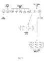
図1を参照すると、座標測定装置(CMM)2の形態の移動構造を備える位置決め装置1が示される。CMM2は、ベース10を含み、ベース10はフレーム12を支持し、フレーム12はクイル14を保持する。モータ(図示せず)は、互いに直交する3つの軸Cx、CYおよびCzに沿ってクイル14を移動させるために設けられる。クイル14は、この実施形態では、レニショー パブリック リミテッド カンパニーから入手可能な、REVO関節ヘッドなどの連続走査関節ヘッドである、関節ヘッド16を保持する。理解されるように、連続走査ヘッドは、少なくとも1つの軸の周りの実質的に任意の角度で、それに取り付けられた装置の配向を可能にし、そして、しばしば無限に近い数の角度配向を提供すると説明される。また、連続走査ヘッドの軸の周りの測定装置の配向は、測定中に変更され得る(例えば、接触プローブに対して変更され、一方で、接触プローブは、検査対象と接触し、スタイラス偏向信号などの測定情報を取得する。)。対照的に、割り出しヘッドは、それに取り付けられた測定装置がロックされ得る、不連続の数の画定された(「割り出し」された)位置を有する。割り出しヘッドを使用すると、測定装置の向きが変更され得るが、測定データの取得中にではない。Referring to FIG. 1, a
関節ヘッド16は、クイル14に取り付けられた基部20、中間部22、およびプローブ保持部24を有する。基部20は、第1の回転軸Bの周りに中間部22を回転させるための第1のモータ(図示せず)を備える。中間部22は、第1の回転軸に対して実質的に垂直である、第2の回転軸A周りにプローブ保持部24を回転させるための第2のモータ(図示せず)を備える。図示されていないが、関節ヘッド16の可動部分間にベアリングが設けられ得る。さらに、図示されていないが、ベース10、フレーム12、クイル14、および関節ヘッド16の部分の相対位置を測定するための測定エンコーダが設けられ得、ベース10に配置されたワークピース8に対する、測定プローブ4の位置が決定され得る。理解されるように、そのような測定値は、以下に、より詳細に説明される関数において使用される、偏向していないスタイラス先端9の位置を決定するために使用され得る。 The articulating
プローブ4は、(この実施形態においては関節ヘッド16を介して)クイル14に取り付けられる。記載された実施形態においては、プローブ4は接触プローブ(例えば、いわゆるアナログ/走査プローブ)である。それは、プローブ本体5と、(接触先端9を有する)偏向可能なスタイラス7を備える。記載される実施形態において、プローブ4は、プローブ保持部24に、取り外し可能に、(例えば、キネマティックマウントを使用して)取り付けられる。記載される実施形態において、プローブ4は、プローブ本体5およびプローブ保持部24の上または中に設けられた、対応する磁石(図示せず)を使用することにより、プローブ保持部24によって保持され得る。プローブ4は、例えば、CMMの移動容積内に配置されるプローブ収納ラック(図示せず)から/へ、自動的に取り付け/取り外し可能であり得る。 The
関節ヘッド16は、プローブ4が、クイル14に対して回転させされることを可能にする。特に、記載される実施形態において、それは、プローブ4が、クイル14に対して、2つの回転自由度の周りに位置決めされることを可能にする。関節ヘッド16によって提供される2つの回転自由度と、CMM2の3つの直線(Cx、CY、CZ)並進軸の組み合わせは、プローブ4が、5自由度で移動/位置決めされることを可能にする。Articulating
位置決め装置1は、また、(例えば、ジョイスティック6などの入力装置を介しての手動、または、例えば、検査プログラムの制御下での自動のいずれかで)CMM2の動作を制御するためのコントローラ26を備える。コントローラ26とのユーザ対話を支援するために、表示装置18が設けられ得る。コントローラ26は、例えば、専用の電子制御システムであり得、および/または、パーソナルコンピュータを含み得る。 The
現行の実施形態において、プローブは、いわゆる「先端感知」プローブであり、スタイラス先端の偏向が直接検出される。そのようなプローブの例は、特許文献5および特許文献8に記載されており、その内容は、その参照により組み込まれる。これらの文献に記載されているように、先端感知プローブは、例えば、スタイラスの先端に向けて(例えば、スタイラスの内部で)指向される光のビームを生成する光源と、ビームを受信し、スタイラス先端の横方向の変位を示す信号を生成するように配置される検出器を備える、光トランスデューサシステムを有することによって実装され得る。ミラーまたは再帰反射装置などの反射要素は、1つまたは複数のセンサ(例えば、プローブ本体内またはプローブ本体に近接するスタイラスの端部に配置され得る。)に向けてビームを反射して戻すために、スタイラス先端の近位のスタイラスの端部またはその近くに(例えば、スタイラス先端またはスタイラスに近接して)配置され得る。先端感知プローブは、いかなる意図されない曲げも感知されるだろうから(例えば、重さ/たるみ/重力/慣性による)、プローブスタイラスの意図されない曲げによって引き起こされる誤差の影響を受けにくい。それにもかかわらず、理解されるように、本発明は、非先端部感知プローブを含む、他の種類のプローブに適用可能である。そのような場合、必要ならば、既知の手法を使用して、ドループなどの他の既知の因子が要因として考慮される必要があるかもしれない。 In the current embodiment, the probe is a so-called "tip-sensing" probe, where deflection of the stylus tip is detected directly. Examples of such probes are described in US Pat. As described in these references, the tip-sensing probe includes, for example, a light source that produces a beam of light that is directed toward (eg, within the stylus) the tip of the stylus; It may be implemented by having an optical transducer system with a detector arranged to produce a signal indicative of lateral displacement of the tip. A reflective element, such as a mirror or retroreflector, may be positioned within the probe body or at the end of the stylus proximate the probe body, for example, to reflect the beam back toward one or more sensors. , may be located at or near the end of the stylus proximal to the stylus tip (eg, proximate the stylus tip or stylus). The tip sensing probe is less susceptible to errors caused by unintended bending of the probe stylus, as any unintended bending will be sensed (eg, due to weight/sag/gravity/inertia). Nevertheless, it will be appreciated that the invention is applicable to other types of probes, including non-tip sensing probes. In such cases, other known factors such as droop may need to be factored in using known techniques, if desired.
図1は、CMM2の最上層の説明のみを提供することが、留意されるべきである。そのような装置のより完全な説明は、他の場所に、見い出され得、例えば、その全内容がその参照により本明細書に組み込まれる、特許文献7が参照される。 It should be noted that FIG. 1 only provides a description of the top layers of the CMM2. A more complete description of such devices can be found elsewhere, see, for example, US Pat.
ワークピース8の測定中、プローブ4の接触先端9は、CMMのX、Y、Z軸(すなわち、Cx、CY、CZ)の動きによって、および/または、A軸および/またはB軸周りの関節ヘッドの回転によって、ワークピース8と接触する。これは、プローブのスタイラス7および先端9が偏向することをもたらす。1つまたは複数のトランスデューサ(図示されないが、この実施形態においては、それらはプローブ本体5内にある)は、その休止位置から離れた、この偏向を検知し、偏向の程度を示す1つまたは複数の信号を提供する。例えば、電圧信号が提供され得る。この実施形態において、3つの別々の信号(例えば、p、q、r)が提供され、それらは、異なる方向、例えば、必ずしもそうとは限らないが、ほぼ互いに直交する方向の偏向に応答する。理解されるように、プローブからの出力は、一般にCMMの座標系と整列しないであろう。また理解されるように、信号は偏向に直線的に比例してもしなくてもよい。During measurement of the
プローブ信号(p、q、r)を利用するためには、それらが空間測定値に変換される必要がある。これは、変換モデルの使用を含む。本実施形態において、これは、プローブ信号(p、q、r)を、プローブの局所座標系(PX、PY、PZ)におけるプローブの偏向を表す、空間測定値に変換/換算することを含む。理解されるように、プローブからの出力は、プローブの局所座標系と整列しなくてもよく、それどころか、互いに直交しなくてもよい。また理解されるように、プローブの局所座標系(PX、PY、PZ)は、CMMの座標系(Cx、CY、CZ)とは無関係であり、プローブは、回転軸の周りに回転させられ得るので、プローブの局所座標系は、それと共に回転する。したがって、必要に応じて、CMM2の座標系Cx、CY、CZ空間における偏向スタイラス先端9の位置の決定を可能にするために、測定値は、CMM2の座標系(Cx、CY、CZ)に回転させられ得る。In order to utilize the probe signals (p, q, r) they need to be transformed into spatial measurements. This includes the use of conversion models. In the present embodiment, this involves transforming/converting the probe signals (p, q, r) into spatial measurements representing the deflection of the probe in its local coordinate system (PX , PY , PZ ). including. As will be appreciated, the outputs from the probe need not be aligned with the probe's local coordinate system, or even orthogonal to each other. It will also be appreciated that the probe's local coordinate system (PX , PY , PZ ) is independent of the CMM's coordinate system (C x , CY , CZ ); so that the local coordinate system of the probe rotates with it. Therefore, if desired, the measurements are taken in the coordinate system of theCMM2(Cx, C Y, CZ ).
例えば、CMMの座標系における偏向された先端位置は、以下の式(1)に示されるよう
に決定され得る。For example, the deflected tip position in the CMM's coordinate system can be determined as shown in equation (1) below.

ここで、(TX、TY、TZ)は、偏向された先端位置であり、(UX、UY、UZ)は、プローブの偏向されていない先端位置(システムおよびヘッドの幾何学的配置から知られる)であり、(DX、DY、DZ)は、決定されたスタイラスの偏向であり、これは、以下でより詳細に説明される。これらの値は、すべてCMMの座標系(CX、CY、CZ)にある。where (TX , TY , TZ ) is the deflected tip position and (UX , UY , UZ ) is the undeflected tip position of the probe (system and head geometry ) and (DX , DY , DZ ) are the determined stylus deflections, which will be explained in more detail below. These values are all in the CMM's coordinate system (CX ,CY ,CZ ).
CMMの座標系(DX、DY、DZ)におけるスタイラスの偏向は、以下の式(2)に示されるように決定され得る。The stylus deflection in the CMM's coordinate system (DX , DY , DZ ) can be determined as shown in equation (2) below.

ここで、(PX、PY、PZ)は、プローブの局所座標系における決定されたスタイラスの偏向であり、これは、以下でより詳細に説明される。式(2)に示される他の2つの行列は、決定されたスタイラス偏向を、A軸およびB軸の周りのプローブの角度に基づいて、CMMの座標系に回転させる。where (PX , PY , PZ ) is the determined stylus deflection in the local coordinate system of the probe, which is explained in more detail below. The other two matrices shown in equation (2) rotate the determined stylus deflection into the CMM's coordinate system based on the probe's angle about the A and B axes.
現在知られているように、例えば、以下の式(3)に示されるような変換モデルを使用して、プローブの局所座標系(PX、PY、PZ)におけるスタイラス偏向を決定するために、プローブの信号p、q、rを変換/変換することが必要である。As is currently known, to determine the stylus deflection in the probe's local coordinate system (PX ,PY ,PZ ) using, for example, a transformation model as shown in equation (3) below: , it is necessary to transform/convert the probe signals p, q, r.

ここで、kPx1、kPy1などは、特定のヘッド角で実行される、標準の既知の較正ルーチンから決定される定数である(例えば、特許文献3に記載される。)。これは、線形変換モデルであるが、理解されるように、これは、必ずしもそうである必要はなく、例えば、非線形変換モデルが使用され得る。where kPx1 , kPy1 , etc. are constants determined from a standard known calibration routine performed at a particular head angle (described, for example, in US Pat. Although this is a linear transformation model, it will be appreciated that this need not be the case, for example a non-linear transformation model could be used.
しかしながら、上述のように、プローブ信号(p、q、r)とスタイラス先端の偏向の間の関係は、A軸およびB軸周りのプローブの向きに応じて変動することが分かった。この変動は、垂直軸(例えば、この実施形態においてB軸)の周りの回転によっても、またプローブが真下に向けられている場合でも存在すると見出された。 However, as noted above, the relationship between the probe signals (p, q, r) and the deflection of the stylus tip was found to vary depending on the orientation of the probe about the A and B axes. This variation was found to be present both with rotation about a vertical axis (eg, the B axis in this embodiment) and even when the probe is pointed straight down.
この偏差(すなわち、スタイラス偏向信号(p、q、r)と、スタイラス先端の偏向の間の関係の変動)は、図2aおよび図2bに示される。図2aにおいて、プローブ4は、関節ヘッドのA軸およびB軸の周りの第1の角度方向、例えばA=0°およびB=0°に位置決めされる。次いで、スタイラス先端は、プローブの「PX」次元において、1mm偏向させられ、それは、示される例では、その時点で、CMMの「CX」次元と整列する。この偏向は、スタイラス先端9をワークピースに垂直に駆動するように、CMMのクイル14(ひいては関節ヘッド16およびプローブ4)を、CMMのCX次元に沿って1mm動かすことによって達成され得る。したがって、スタイラス先端9は、CMM運動の程度、すなわち1mmに等しい量だけ偏向する。示されるように、これは、プローブ信号p=1V、q=0.1V、および、r=0.05Vを生じさせる。qおよびrの小さな読みは、プローブ設定における不完全性(例えば、トランスデューサのスタイラスとのわずかな位置合わせ不良)に起因し得、または、プローブが、p、q、および、rが、プローブのPX、PY、および、PZ座標系と、完全に整列しないように構成されていることに起因し得る。This deviation (ie, the variation in the relationship between the stylus deflection signals (p, q, r) and the deflection of the stylus tip) is shown in Figures 2a and 2b. In FIG. 2a the
プローブは、次に、B軸の周りに90°回転させられ(図2bを参照)、その後、同じプロセスが繰り返される。すなわち、スタイラス先端9は、プローブの「PX」次元において1mm偏向させられ、それは、その時点で、今のところCMMの「CY」次元と整列する。これは、スタイラス先端9を、ワークピースに垂直に駆動するように、CMMのクイル14(したがって、関節ヘッド16およびプローブ4)を、CMMのCY次元に沿って1mm動かすことによって達成され得る。示されるように、これは、スタイラス偏向信号p=0.9V、q=0.07V、および、r=0.04V(「V」=ボルト)を生じさせる。The probe is then rotated 90° about the B-axis (see Figure 2b), after which the same process is repeated. That is, the
示されるように、同じスタイラス偏向に対して、同じプローブ次元において、異なるスタイラス偏向信号が提供される(すなわち、異なるp、q、および/または、r出力が経験される)。これは、pによる1V出力が、すべての向きに対して、プローブの「PX」次元における同量の偏向に関連していないことを意味する。As shown, different stylus deflection signals are provided (ie, different p, q, and/or r outputs are experienced) in the same probe dimension for the same stylus deflection. This means that a 1 V output due to p is not associated with the same amount of deflection in the 'PX ' dimension of the probe for all orientations.
この偏差を説明する別の方法は次のとおりである。第1の向きで(例えば、A=0°、および、B=0°)、閾値p信号レベルが出力されるまで(例えばp=1V)、第1の軸に沿って(例えば、CX軸に沿って)、クイルを動かすことによって、スタイラス先端9をワークピースに垂直に駆動し、最初の接触点と閾値信号が達成された点の間の、CX軸に沿った、クイルにより移動させられた距離を記録する。次に、プローブは、新しい向き(例えば、A=0°、および、B=90°)に回転させられ、今度は、CY軸に沿ったクイルの動きによってであるが、プロセスが再び繰り返される。本発明者らは、閾値p信号レベル(p=1V)に達する前に、クイルによって移動させられた距離が、向きに応じて変化することを確認した。したがって、例えば、p=1Vの前に、CX次元で移動させられた距離(したがって、B=0°のときのプローブの「PX」次元におけるスタイラスの偏向)は、1mmであり得、一方、p=1Vの前に、CY次元で移動させられた距離(したがって、B=90°のときのプローブの「PX」次元におけるスタイラスの偏向)は、1.1mmであり得る。Another way to explain this deviation is as follows. In a first orientation (e.g. A=0° and B=0°), along a first axis (e.g. CX -axis ), driving the
いずれにせよ、理解されるように、プローブの向きに応じてプローブ信号に誤差があるように見え、それは、それらのプローブ信号から得られた空間測定値に至るであろう。そのような明白なプローブ誤差は、それから得られる空間測定値に誤差を生じさせるであろう。 In any event, as will be appreciated, there will be errors in the probe signals depending on the orientation of the probe, leading to spatial measurements obtained from those probe signals. Such apparent probe errors will cause errors in the spatial measurements obtained therefrom.
上記の例は、B軸位置に関する明白なスタイラスの偏向挙動の変動を例示するが、明白なスタイラスの偏向挙動の変動は、また、A軸位置によっても変動し得ることが見出された。 Although the above examples illustrate variations in apparent stylus deflection behavior with respect to B-axis position, it has been found that variations in apparent stylus deflection behavior can also vary with A-axis position.
したがって、プローブ信号(p、q、r)を、プローブの局所座標系(PX、PY、PZ)におけるプローブの偏向を表す空間測定値に変換/換算すること(および、任意で、結果をCMM2の座標系(CX、CY、CZ)に回転させること)に加えて、本実施形態の方法は、プローブの向きに基づいて、プローブ信号(p、q、r)とスタイラス先端の偏向の間の関係における変動も補正する。Therefore, converting/converting the probe signals (p, q, r) into spatial measurements representing the deflection of the probe in the probe's local coordinate system (PX , PY , PZ ) (and, optionally, the result to the coordinate system of the CMM2 (CX , CY , CZ )), the method of the present embodiment also applies probe signals (p, q, r) and stylus tip It also corrects variations in the relationship between the deflections of .
そのような変動は、主に、装置、例えば、CMM2および/または関節ヘッド16の剛性特性によると思われる。力がスタイラス先端9に印加されると、スタイラス7は、プローブ本体5に対して偏向し、それは、プローブのトランスデューサによって検出される。しかしながら、印加された力の方向および大きさに依存するであろう、関節ヘッド16および/またはCMM2構造のいくらかの変換されない偏向もまた存在するであろう。この変換されない偏向は、スタイラスの偏向測定における同等の誤差と区別がつかない。 Such variations appear to be primarily due to the stiffness properties of the device, eg
この誤差を克服するための例示的な技術が、図3から図14を参照して説明されるであろう。この技術は、1つまたは複数のプローブ信号と、スタイラスの休止/ゼロ力位置からの偏向との間の関係における変動を決定し、モデル化するためのモデルを生成することを含む。この特定の例において、モデルは、それによって、関節ヘッド軸の周りの異なる向きで、スタイラス偏向信号とスタイラスの偏向との関係における相違を補償するために、包括的な変換モデル(プローブ信号を次元測定値に変換/換算するために使用される)に組み込まれる。 An exemplary technique for overcoming this error will be described with reference to FIGS. 3-14. The technique involves generating a model to determine and model variations in the relationship between one or more probe signals and stylus deflection from a rest/zero force position. In this particular example, the model thereby employs a comprehensive transform model (probe signal dimension used to convert/convert measurements).
図3は、プローブ4についてそのような変換モデルを決定するプロセス100のための最上位フローチャートを提供する。この方法は、プローブ4を中立にするオプションのステップ102で始まる。これは、アナログ/走査プローブのための標準的な周知のプロセスであり、それによって、プローブが自由空間にあるときに(すなわち、スタイラスが休止した/偏向されない位置にあるときに)、プローブのトランスデューサ信号が測定される。 FIG. 3 provides a top-level flowchart for
ステップ103において、CMMの測定容積内に配置された較正アーチファクト30が、プローブ4を用いて、それのいくつかの測定値を取得することによって検索される。この段階で、デフォルトの変換モデルが、プローブ信号を位置測定値に変換るために使用され得る。 In
ステップ104において、プローブ信号変換モデルが検索される。これは、図4を参照してより詳細に説明される。 At
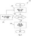
次に、ステップ106において、プローブ信号とスタイラスの偏向の間の関係が、関節ヘッドの角度と共にどのように変化するかを記述する、補正モデルが決定される。これは、図5を参照してより詳細に説明される。 Next, at
次いで、ステップ104で決定されたプローブ信号変換モデル、および、ステップ106で決定された補正モデル(本発明の目的のために、まとめて「変換モデル」として言及され得る)は、続いて、例えば、図6を参照して以下により詳細に説明するように、スタイラス偏向信号を正確な空間測定値に変換するために使用され得る。 The probe signal transformation model determined in
図4を参照すると、プローブ信号変換モデルを検索するための例示的なプロセス200が示される。プロセスは、物品、この場合には、較正アーチファクト30が、第1の関節ヘッド角(例えば、この実施形態では、A=0°およびB=0°)で測定される、ステップ202で始まる。この実施形態において、ステップ202における測定動作は、スタイラスの先端が球体32に対して付勢された状態で、クイル14を球体32の周りの円の中で並進運動させることによって、較正アーチファクトの球体32(図7a参照)の走査(例えば、赤道34の周り)を実行することを含む。この走査は、異なるスタイラス偏向(異なる測定力)で繰り返される。また、走査は、例えば、特許文献2に記載されているように、複数の走査方向に実行され得る。 Referring to FIG. 4, an
ステップ202における測定動作は、また、球体の周りで間隔をあけて、例えば、図7aに示される点36において、点測定(例えば、4点測定)を行うことを含む。各々の点測定は、スタイラスの偏向信号が、スタイラスの偏向のある範囲、例えば、名目上、50μm(ミクロン)~200μm(ミクロン)の間にわたって得られることを可能にするために、スタイラスの尖端9を球体32内に垂直に押すことを含む。 The measuring operation in
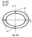
ステップ202で得られた測定結果の例は、図8a、8b、および、8cに概略的に示される。図8aは、測定値の読み取りが行われたCX、CY位置を概略的に説明する、チャートを示す。各点は、1回の測定値の読み取りが行われた位置を表す。図から分かるように、走査は、CMM2のクイル14を、円の中で移動させることを含み、接触点(図8aの領域36‘で強調表示される)は、球体32へと、および、球体32から離れて、名目上真っ直ぐのライン内に移動させることを含んだ。図8aのチャートは、B=0°とB=90°の両方に有効である。Examples of measurement results obtained in
図8bは、A=0°およびB=0°のときに、図8aで識別された各測定点において記録された、プローブのスタイラス偏向信号(p、q)を示す。CMM2のクイル14は、円をなして動かされ、球体の赤道34のプロファイルは円形であるので、プローブの「q」信号に対してプロットされた「p」信号のプロファイルは、また、円形であると期待される。しかしながら、図8bに示されるように、qに対するpのプロファイルは楕円形であり、この場合、長軸はp軸に沿って延びる。これは、pとqに対するプローブ信号の挙動の明らかな相違によるものである(例えば、この場合において、そして、示されるように、pは、所定の偏向に対して、qよりも、応答性が高い/より大きい信号を提供するように見える。 FIG. 8b shows the probe stylus deflection signals (p,q) recorded at each measurement point identified in FIG. 8a when A=0° and B=0°. Since the
次に、ステップ204で、異なるヘッド角で、測定が必要とされるかどうかが決定される。この実施形態において、測定は、より多くのヘッド角で得られ得るが、測定は、2つの異なるヘッド角で得られるべきである(そして、AおよびB角度の任意の組み合わせが用いられ得る)。したがって、ステップ206において、関節ヘッド16は、プローブを、第2の関節ヘッド角(例えば、この実施形態では、A=0°、B=90°)に向け直すように操作される。次いで、ステップ202が繰り返され、上述の測定(例えば、2回の走査および4点の測定)が、第2の関節ヘッド角(図7bに示される)で繰り返される。上述のように、図8aのチャートは、測定が、走査および点測定中に行われる点での、クイル14のCX、CY位置を示すために等しく適用可能である。Next, at
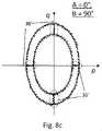
図8cは、A=0°およびB=90°のときに、図8aで識別された各々の測定点において記録された、プローブのスタイラス偏向信号(p、q)を示す。図からわかるように、qに対するpのプロファイルは、図8bに示されるそれに似て楕円形であるが、図8bと比較してわかるように、主軸は、90°回転している(この場合、主軸は、図8cのq軸に沿って延びる)。図示されるように、AおよびB=0°のときの状況とは異なり、この場合、qは、所定の偏向に対して、pよりも、応答性が高い/より大きい信号を提供するように見える。 FIG. 8c shows the stylus deflection signals (p, q) of the probe recorded at each measurement point identified in FIG. 8a when A=0° and B=90°. As can be seen, the profile of p versus q is elliptical like that shown in FIG. 8b, but the major axes are rotated 90° (in this case, The principal axis runs along the q-axis in FIG. 8c). As shown, unlike the situation when A and B=0°, in this case q provides a more/more responsive signal than p for a given deflection. appear.
したがって、プローブによって得られた測定値には誤差であるように見えるものが存在することが分かる。プローブ信号の挙動は、プローブの向きに応じて異なるように見える。言い換えれば、向きに応じてプローブ信号の利得に変動があるように見える。しかしながら、また、分かるように、誤差は、プローブと共に回転しないので、誤差は機械の構造から生じる可能性が高いと推定され得る。 Therefore, it can be seen that there is what appears to be an error in the measurements obtained by the probe. The behavior of the probe signal appears different depending on the orientation of the probe. In other words, there appears to be variation in the gain of the probe signal depending on orientation. However, as can also be seen, the error does not rotate with the probe, so it can be assumed that the error likely arises from the construction of the machine.
ステップ204で、この段階でそれ以上の測定は必要ないことが、その結果、決定され、プロセスは、ステップ208へ進む。ステップ208で、最小二乗最良適合最適化プロセスが、プローブ信号変換モデルを決定するために使用される。例えば、以下の式(4)を参照すると、偏向されていない先端位置Ux、Uy、Uz位置は既知であり、プローブ信号p、q、rは既知であり、ヘッド角AおよびBは既知であり、スタイラス先端位置Tx、Ty、Tzは、全て球体の表面上にあるべきことが既知である。したがって、最小二乗最良適合最適化プロセスなどの最適化プロセス(例えば反復プロセス)が、以下の式(4)に示されるブランク3×3行列の値を推定するために使用され得、これは、球体の表面にできるだけ近くなるように、B=0°およびB=90°で得られる測定値をもたらすであろう。 At

その行列は、その後、プローブ信号変換モデルとして使用され得る。例示的な行列は、例えば、上記の式(3)に示されるもの、例えば、以下のものと同様であり得る。 That matrix can then be used as a probe signal transformation model. An exemplary matrix can be, for example, similar to that shown in equation (3) above, such as:

しかしながら、この場合、プローブ信号変換モデルは、多くの異なる方向で得られた測定値から決定されるので、プローブ信号変換モデルは、「平均化」、「結合化」「統合化」または「最適化」プローブ信号変換モデルとして記述され得る(それに対して、式(3)では、行列は、ただ1つのヘッド方向で得られた測定値から決定されたであろう)。任意選択で、プローブ信号変換モデルは、複数の異なる向きから決定され、その後、複数の異なる向きに対する共通の変換モデルとして使用されるので、「共通の」プローブ信号変換モデルとして記述され得る。理解されるように、このプローブ信号変換モデルは、向き非依存の信号変換モデルの一例である。入力パラメータとして、どの軸についてのプローブの向きも使用しない。 However, in this case, since the probe signal transformation model is determined from measurements taken in many different directions, the probe signal transformation model can be "averaged", "combined", "integrated" or "optimized". ' probe signal transformation model (whereas in equation (3) the matrix would have been determined from measurements taken in only one head orientation). Optionally, the probe signal transformation model may be described as a "common" probe signal transformation model, as it is determined from multiple different orientations and then used as a common transformation model for multiple different orientations. As will be appreciated, this probe signal transformation model is an example of an orientation independent signal transformation model. It does not use the orientation of the probe about any axis as an input parameter.
理解されるように、適切な異なるヘッド角で測定を行うことによって、プローブ座標系において、CMMの影響は、ゼロに平均化され得る。 As will be appreciated, by making measurements at appropriate different head angles, the CMM effects can average to zero in the probe coordinate system.
理解されるように、測定が行われる順序は、本発明にとって重要ではない。例えば、全ての測定を第1の関節ヘッド角で行い、次いで第2の関節ヘッド角で全ての測定を行うのではなく、第1及び第2の関節ヘッド角で(または3つ以上のヘッド角度が存在する場合は全てで)測定を得ることが、交互に行われ得る。 As will be appreciated, the order in which the measurements are made is not important to the invention. For example, rather than making all measurements at a first joint head angle and then all measurements at a second joint head angle, at first and second joint head angles (or three or more head angles). Obtaining measurements (if any) may alternately be performed.
さらに、異なる関節ヘッド角のそれぞれで同じ測定値が得られることは必要ない。例えば、4つの異なる関節ヘッド角に対してデータが得られるべきということがあるかもしれないし(例えば、A=0°およびB=0°、45°、90°および135°)、各々の関節ヘッド角に対して走査測定を実行するのではなく、4つの関節ヘッド角のうちの2つのみに対して走査測定が実行され得る(一方で、例えば、4つの全ての関節ヘッド角に対して点測定が依然として行われる)。 Furthermore, it is not necessary that the same measurements be obtained at each different joint head angle. For example, it may be that data should be obtained for four different articulation head angles (e.g., A=0° and B=0°, 45°, 90° and 135°) and each articulation head Rather than performing scan measurements on the angles, scan measurements may be performed on only two of the four joint head angles (while, for example, point measurements are performed on all four joint head angles). measurements are still taken).
理解されるように、他の種類の測定値が、上記のそれの代わりに、または、上記のそれと共に得られ得る。例えば、較正用アーチファクトの表面のスパイラル走査が実行され得る。また、記載された実施形態において、異なるスタイラスの偏向/力で測定値が得られるが、異なるスタイラスの偏向/プローブ力で測定値が得られることは必要ない。例えば、各ヘッド角で実行されるただ一回の走査であり得る。この場合、利得の形は、例えば、線形で、0を横切ると仮定され得、または、例えば、仮定の非線形を有すると仮定され得る。プローブ信号の利得誤差がマッピングされると確信することは不可能であろうが、これは、いくつかの誤差が識別されることを可能にするだろう。あるいは、複数のスタイラスの偏向/プローブ力での測定値は、ある(例えば、1つの)ヘッド角では得られ得るが、他のヘッド角では得られ得ない。 As will be appreciated, other types of measurements may be obtained instead of or in addition to those described above. For example, a spiral scan of the surface of the calibration artefact can be performed. Also, although in the described embodiment measurements are obtained at different stylus deflections/forces, it is not necessary that measurements be obtained at different stylus deflections/probe forces. For example, there may be only one scan performed at each head angle. In this case, the gain shape may be assumed to be linear, crossing zero, for example, or may be assumed to have an assumed non-linearity, for example. It may not be possible to be sure that the gain error of the probe signal will be mapped, but this will allow some errors to be identified. Alternatively, multiple stylus deflection/probe force measurements may be obtained at one (eg, one) head angle but not at other head angles.
図5を参照すると、ヘッド角に依存するプローブ信号とスタイラス偏向の間の関係における変動を記述する補正モデルを決定するための例示的なプロセス300が示される。プロセスは、ステップ302で、CMM2を作動させることにより開始し、較正球体32を(所定のヘッド角度で)、多数の異なるスタイラス偏向で走査する。例えば、これは、所定の公称Aヘッド角、例えば、A=30°(図11参照)で、球体32の表面の周りに円を走査することを含み得る。この実施形態において、走査は、関節ヘッドの回転軸の周りにプローブを回転させることによって行われる。示されるように、球体32およびスタイラス先端9が半径を有するため、プローブはA軸の周りに回転させられる必要があり、したがって、Aは実際には30°ではない。しかしながら、線38が、関節ヘッドの回転点と、その周りに走査が行われる円40の中心との間に延びる、A軸の周りの角度は30°であり、したがって、Aは公称30°であると記述される。また、理解されるように、プローブがAの周りに回転させられるように示される量は、プローブと較正アーチファクトとの相対的な縮尺のために、図面において大きく誇張されている。さらに、理解されるように、走査が、関節ヘッドの1つまたは複数の軸の周りにプローブを回転させることによって行われるのではなく、走査は、CMMのX、Y、および、Z軸を用いてクイル14を並進移動させることによって行われ得る。この場合、ヘッドのA軸は本当に30°であり得る。 Referring to FIG. 5, an
同じ走査が、少なくとも2つの異なるスタイラス偏向(例えば、2つの異なるプローブ力)で実行され、この場合は、4つの異なるスタイラス偏向で実行される。理解されるように、これは、必ずしもそうである必要はない。例えば、測定は、ただ1つのスタイラスの偏向で実行され得る。これは、例えば、将来の測定値がそのスタイラスの偏向で得られさえすればよい場合、および/または、利得における変動について仮定が立てられ得る場合(例えば、ゼロに戻る線形変動)に、特に当てはまる。 The same scan is performed with at least two different stylus deflections (eg, two different probe forces), in this case with four different stylus deflections. As will be appreciated, this need not necessarily be the case. For example, measurements can be performed with just one stylus deflection. This is particularly true, for example, if future measurements only need to be obtained with that stylus deflection and/or if assumptions can be made about variations in gain (eg linear variations back to zero). .
次にステップ304で、異なるヘッド角で測定が必要であるかが判定される。この実施形態において、測定値は、4つの異なる公称A軸角度(30°、45°、60°および90°;A=90°については図12参照)で得られることになる。したがって、ステップ306において、関節ヘッド16は、プローブを次の公称A軸ヘッド角に再配向するように操作される。次いで、ステップ302が、新しい公称ヘッド角について上記のように繰り返される。このループは、ステップ304で、異なるヘッド角でのそれ以上の測定が必要とされないと決定されるまで続く。 Next, at
プロセス300の制御は、次にステップ308に進み、そこでスタイラス偏向信号ゲインがヘッド角度と共にどのように変動するように見えるかが決定される。ステップ308(そのための例示的な方法が以下により詳細に説明される)は、概略的に、以下i)~iii)のように要約され得る。i)各走査から測定距離(測定された直径、半径、楕円率など)を抽出する、ii)その測定距離がスタイラスの偏向/力によってどのように変化するかを決定する、iii)次に、その変化((ii)で決定される)の傾きが、いかにヘッド角について変動するかを決定する。 Control of
例えば、式(4)の行列を用いて、図5のプロセスの走査中に得られたプローブ信号は、位置測定値に変換される。次に、各走査からの位置測定値は、球体32の測定された直径を決定するために分析される。これは、各ヘッド角での各スタイラスの偏向に対して行われる。説明の目的のために、異なる公称Aヘッド角および異なるスタイラス偏向に対し、スタイラス偏向に対する球の測定された直径が、図9に示される。分かるように、この例では、任意の所定のヘッド角に対して、測定された球体32の直径は、スタイラスの偏向と共に増加する。理解されるように、点に当てはめられた各線の勾配は、各ヘッド角に対する見かけのプローブ信号利得を表す。図示のように、各ヘッド角度は異なる勾配を有し、したがって、異なる見かけ上の利得を有する。これは、プローブ信号の利得がヘッド角度と共に変化するように見えることを示す。言い換えれば、この例によって例示されるように、プローブ信号とスタイラスの偏向の程度との間の関係はヘッド角度と共に変化する。 For example, using the matrix of equation (4), the probe signals obtained during scanning of the process of FIG. 5 are converted into position measurements. The position measurements from each scan are then analyzed to determine the measured diameter of
図10aは、Aヘッド角度30°、45°、60°および90°に対する傾斜度/利得値のプロットを概略的に示す。見かけの利得変動は関数で表され得る。例えば、A軸周りのヘッドの角度に依存する見かけの利得変動は、以下の式(5)に示される関数によってモデル化され得る。 FIG. 10a schematically shows plots of tilt/gain values for A head angles of 30°, 45°, 60° and 90°. Apparent gain variation can be expressed as a function. For example, the apparent gain variation depending on the angle of the head about the A-axis can be modeled by the function shown in equation (5) below.

ここで、k1、k2およびk3は、測定された利得に適合するように選択された定数である(例えば、関数が、測定された利得に適合する、図10aに示される線を記述するように)。where k1 , k2 and k3 are constants chosen to fit the measured gain (e.g. the function describes the line shown in FIG. 10a to fit the measured gain). to do).
次に、これは、測定中に利得における見かけの変動を補正するために使用され得る行列に組み込まれ得る。例えば、以下の式(6)は、式(3)に示される変換モデルに加えて、異なるヘッド角度での、プローブ信号の利得における見かけ上の変動をモデル化し、それを補償するために使用され得る行列を含む、変換モデルの例を示す。 This can then be incorporated into a matrix that can be used to correct for apparent variations in gain during measurements. For example, equation (6) below, in addition to the transformation model shown in equation (3), is used to model and compensate for the apparent variation in gain of the probe signal at different head angles. We show an example of a transformation model, including the resulting matrix.

理解されるように、Gxyが関数であるのとは対照的に、それは代わりにルックアップテーブルであり得る。したがって、見かけの利得変動は、ルックアップテーブルによってモデル化され得る。必要であれば、直接測定されない値を入力/決定するために、ルックアップテーブルの補間が使用され得る。As will be appreciated, it could instead be a lookup table, as opposed to Gxy being a function. Apparent gain variation can thus be modeled by a lookup table. If necessary, lookup table interpolation can be used to enter/determine values that are not directly measured.
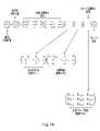
参照を容易にするために、異なるヘッド角での、プローブ信号とスタイラスの偏向の間の関係における変動を補償するように、見かけの利得変動をモデル化する上述の行列を組み込むための、拡大された形での式(1)が、図13に示される。図13は、また、理解を助けるために、それらの目的が何のためであるのかを説明するために、様々な行列を細分化してラベル付けしている。 For ease of reference, an expanded version of the above matrix that models apparent gain variation to compensate for variations in the relationship between probe signal and stylus deflection at different head angles. Equation (1) in squared form is shown in FIG. Figure 13 also subdivides and labels the various matrices to explain what their purpose is to aid understanding.
上述の実施形態において、利得は、線形であると仮定される(したがって、例えば、図9の点にフィットするような直線が示される)。しかし、理解されるように、これは必ずしもそうである必要はなく、利得は非線形であり得る(この場合、点にフィットする線は、湾曲し得る)。 In the embodiments described above, the gain is assumed to be linear (so, for example, a straight line is shown to fit the points in FIG. 9). However, as will be appreciated, this need not be the case and the gain may be non-linear (in which case the line fitted to the points may be curved).
式(5)の関数は、異なるA角度で実行される走査が測定された、B角度を真に代表するだけである。A角度に依存する見かけの利得変動は、全てのB角度で同じであると仮定することができ、あるいは、見かけの利得変動がB角度に対してどのように変動するかを予測することが可能である。しかしながら、仮定/予測がなされないことが好ましいなら、そのときには、B角度周りの変動に対して考慮し、モデル化することが可能である。この場合、上述した図5、11、12のプロセスは、異なる(公称)B角度で繰り返され得、それによって、異なるAおよびB角度に対する利得が見出される。図10bは、傾斜角/利得が、AおよびBの角度に対してどのように変動し得るかを概略的に示し、ドットは、異なるAおよびBの角度に対して決定された利得を表す。この変動は、関数で表され得る。例えば、AおよびB角度に依存する見かけの利得変動は、以下の式(7)に示される関数によってモデル化され得る。 The function of equation (5) is only truly representative of the B angles at which scans performed at different A angles were measured. The apparent gain variation depending on the A angle can be assumed to be the same for all B angles, or it is possible to predict how the apparent gain variation varies with B angle. is. However, if it is preferred that no assumptions/predictions are made, then it is possible to account for and model for variations around the B angle. In this case, the processes of FIGS. 5, 11, 12 described above can be repeated at different (nominal) B angles, thereby finding gains for different A and B angles. FIG. 10b schematically shows how the tilt angle/gain can vary for A and B angles, with the dots representing the gain determined for different A and B angles. This variation can be expressed as a function. For example, the A and B angle dependent apparent gain variation can be modeled by the function shown in equation (7) below.

ここで、here,

であり、kBijは、測定された利得に適合するように選択された定数(例えば、測定された利得に適合される図10bに示される表面を記述する関数)である。and kBij is a constant chosen to fit the measured gain (eg a function describing the surface shown in FIG. 10b fitted to the measured gain).
理解されるように、上記のGxy関数は、単なる例示的な関数である。理解されるように、他の関数が使用され得る。 As will be appreciated, the Gxy functions above are merely exemplary functions. As will be appreciated, other functions can be used.
上記の技法は、見かけの利得変動が対称的であると仮定している(例えば、PxおよびPyにおいて)。方法は、利得変動における任意の見かけの非対称性(例えば、PxおよびPyにおける任意の非対称性)を記述するモデルを含むように拡張され得る。たとえば、非対称性が存在すする場合、走査は円形でないだろう。例えば、それらはほぼ楕円形であり得、その場合、見かけの利得変動の楕円形の性質をモデル化することを試みることが有利であり得る。したがって、単純に直径を決定することの代わりに、走査の楕円率が決定され、モデル化され得る。図14は、追加の行列が、任意の見かけの非対称(例えば楕円形)利得変動を補正するために使用され得ることを示す。 The above technique assumes that the apparent gain variation is symmetrical (eg, in Px and Py). The method can be extended to include models that describe any apparent asymmetry in gain variation (eg, any asymmetry in Px and Py). For example, if asymmetry is present, the scan will not be circular. For example, they may be approximately elliptical, in which case it may be advantageous to attempt to model the elliptical nature of the apparent gain variation. Therefore, instead of simply determining the diameter, the ellipticity of the scan can be determined and modeled. FIG. 14 shows that additional matrices can be used to correct for any apparently asymmetric (eg, elliptical) gain variations.
この場合、多数のスタイラスの偏向に対しての走査の直径(または半径)を決定し、それがスタイラスの偏向によってどのように変化するかを決定するのと同時に、他の測定距離が、また、決定され得る。例えば、測定距離は、走査の楕円形(これはパラメータによって記述され得る)であり得、そして、上述の実施形態と同様の方法で、楕円形が偏向に対してどのように変化するかを決定することが必要であり、その変動の傾斜が、所定のヘッド角での(図14に示される非対称利得変動モデルの)楕円利得Ec Esを決定するために使用され得る。 In this case, while determining the scan diameter (or radius) for multiple stylus deflections and how it varies with stylus deflection, the other measured distances are also: can be determined. For example, the measured distance can be the scan ellipse (which can be described by a parameter), and then determine how the ellipse changes with deflection in a manner similar to the above embodiment. and the slope of that variation can be used to determine the elliptic gain Ec Es (of the asymmetric gain variation model shown in FIG. 14) at a given head angle.
ヘッド角に対するEc Esの変動は、以前と同様にモデル化され得る。したがって、理解されるように、図14に示される、非対称利得変動モデルのEcおよびEsは、それぞれ、入力/変数としてヘッド角Aおよび/またはBを有する関数であり得る。例えば、EcおよびEsは、以下の式(8)および(9)に示されるような関数を含み得る。 The variation of Ec Es with head angle can be modeled as before. As will be appreciated, therefore, Ec and Es of the asymmetric gain variation model, shown in FIG. 14, can be functions with head angles A and/or B, respectively, as inputs/variables. For example, Ec and Es may include functions as shown in equations (8) and (9) below.

ここで、here,

であり、そして、and

ここで、here,

であり、そしてcBijおよびsBijは、楕円利得における測定された変動に適合するように選択された定数である。and cBij and sBij are constants chosen to fit the measured variation in elliptic gain.
理解されるように、他の形状の変動が存在し得(例えば、変動が厳密に楕円形ではないような)、その場合、わずかに異なるモデルが必要とされるかもしれない。 As will be appreciated, variations of other shapes may be present (eg, such that the variations are not strictly elliptical), in which case a slightly different model may be required.
理解されるように、図13の利得変動モデル、および、図14の非対称および対称利得変動モデルは、向き依存型プローブ信号変換モデルであると説明され得る。それらは、入力パラメータとして、関節ヘッドの少なくとも1つの軸(この場合においては両方の軸)の周りの接触アナログプローブの向きをとる。 As will be appreciated, the gain variation model of FIG. 13 and the asymmetric and symmetric gain variation models of FIG. 14 can be described as orientation dependent probe signal transformation models. They take as an input parameter the orientation of the contact analog probe about at least one axis (in this case both axes) of the articulating head.
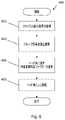
図6は、接触アナログプローブ4を使用して、その後の測定点の収集中に、利得変動モデルが、実際に、どのように使用され得るかの例示的なプロセス400を示す。プロセスはステップ402で始まり、その間に、スタイラス7(特にスタイラス先端9)を、対象に接触させるように、対象8および/または接触アナログプローブ4が動かされ、それによって、スタイラスが偏向することをもたらす。接触アナログプローブは、偏向に応答して、信号(この場合はp、q、r信号)を提供し、信号のレベルは、偏向の程度を示す。理解されるように、信号は、形式がデジタルまたはアナログであり得る。ステップ404において、共通プローブ信号変換モデルは、信号を、プローブ座標系(Px,Py,Pz)における空間測定値に変換するために使用される。ステップ406で、関節ヘッドのA軸およびB軸周りの接触式アナログプローブの向きに応じて、利得変動補正因子を適用するために、プローブ信号利得変動モデルが使用される。したがって、これは、接触アナログプローブが、プローブ信号が提供された点に向けられた、A軸およびB軸周りの角度を、モデルに供給することを含む。これは、次に、プローブ信号の利得の見かけ上の変動に対して補正された、プローブの座標系(Px、Py、Pz)における空間測定値が与える。ステップ408において、(例えば、図13および図14に示される行列を使用して)、空間測定値は、CMMの座標系に回転させられる。次に、これは、偏向されない先端位置(システムとヘッドの幾何学的配置から知られ得、例えば、CMMのX、Y、Z軸に取り付けられたリニア位置エンコーダと、関節ヘッドに取り付けられた回転位置エンコーダから推定され、その結果、関節ヘッドの位置と向きが決定され得る)に加えられ得る。 FIG. 6 shows an
したがって、測定値が、対象の表面に沿って接触式アナログプローブを走査することによって得られ、その間に、接触式アナログプローブ4の向きが、関節式プローブヘッドの1つ以上の軸の周りで連続的に変化する実施形態において、利得変動モデルによって適用される利得補正因子は、1つまたは複数の軸の角度に応じて連続的に変化する(例えば、軸周りの向きの連続的な変化に伴って連続的に変化する)。 Measurements are thus obtained by scanning the contact analog probe along the surface of the object, while the orientation of the
上記の実施形態は、初期プローブ信号変換(「共通」プローブ信号変換モデル)および(非対称および対称)利得変動モデルに対して、別々の行列を有することによって説明されるが、理解されるように、必ずしもそうである必要はなく、それらは、1つの共通の行列によって提供され得る。また上記で説明したように、1つまたは複数の行列を使用するのではなく、代わりに、関数またはルックアップテーブルが使用され得る。 While the above embodiments are illustrated by having separate matrices for the initial probe signal transformation (the "common" probe signal transformation model) and the (asymmetric and symmetric) gain variation models, it should be understood that Not necessarily, they can be provided by one common matrix. Also, as explained above, rather than using one or more matrices, functions or lookup tables may be used instead.
上述の実施形態において、共通のプローブ信号変換モデルは、いくつかの異なる向きで得られた測定値から決定される。理解されるように、この共通プローブ信号変換モデルは、追加の利得変動モデルなしに、自身の能力において使用され得る。そうすることは、挙動における変動が、平滑化/平均化され得るので、ただ1つの向きで得られた測定値からプローブ信号変換モデルを決定し、次に同じプローブ信号変換モデルが他の向きにも適用されると仮定する(そして、単に、空間測定値をCMMの座標系に回転させる)ことより有利であり得る。 In the embodiments described above, a common probe signal transformation model is determined from measurements taken at several different orientations. As will be appreciated, this common probe signal transformation model can be used in its own right without additional gain variation models. Doing so allows determining the probe signal transformation model from measurements taken in only one orientation, as variations in behavior can be smoothed/averaged, and then the same probe signal transformation model in the other orientation. also applies (and simply rotate the spatial measurements to the CMM's coordinate system).
上記の実施形態は、PxおよびPyを補正する。理解されるように、同じ技術は、Pzを補正するために使用され得る。この場合、プローブPz軸に沿った測定が、異なるスタイラスの偏向で(例えば、プローブ「端部」で較正アーチファクトに触れることによって)行われ得る。 The above embodiment corrects for Px and Py. As will be appreciated, the same technique can be used to correct for Pz. In this case, measurements along the probe Pz-axis can be made at different stylus deflections (eg, by touching the calibration artefact with the probe "end").
記載の実施形態において、座標位置決め装置は、直列CMM(すなわち、3つの線形自由度が3つの独立した直交運動軸によって提供される)である。しかし、理解されるように、本発明は、平行CMM、ロボットアーム、またはそれに類するもののような、他の種類の座標位置決め装置の移動を制御するためにも使用され得る。本発明は、専用のCMMだけでなく、工作機械のような他の種類の座標位置決め装置とも、使用され得る。さらに、理解されるように、本発明は、極座標および球面座標位置決め装置のような、デカルトおよび非デカルト位置決め装置と共に使用するのにも適している。 In the described embodiment, the coordinate positioning device is a serial CMM (ie, three linear degrees of freedom are provided by three independent orthogonal axes of motion). However, it will be appreciated that the present invention can also be used to control movement of other types of coordinate positioning devices, such as parallel CMMs, robotic arms, or the like. The present invention can be used not only with dedicated CMMs, but also with other types of coordinate positioning equipment such as machine tools. Further, as will be appreciated, the present invention is also suitable for use with Cartesian and non-Cartesian positioners, such as polar and spherical positioners.
Claims (15)
Translated fromJapanese前記関節ヘッドの前記少なくとも1つの軸の周りで、複数の異なる向きに配置された前記アナログ接触プローブによって得られた測定データを取得するステップと、
前記測定データから、前記少なくとも1つの軸の周りの前記アナログ接触プローブの前記向きに応じた、少なくとも1つのプローブ信号の利得における、任意の見かけ上の変動をモデル化する、少なくとも1つの利得変動モデルを決定することを含み、
前記少なくとも1つのプローブ信号の利得は、前記少なくとも1つのプローブ信号が、スタイラスの偏向に対して、どのように変動するかを定量化することを特徴とする方法。A method of calibrating ananalog touch probe having a deflectable stylus and configured to provide at least one signal indicative of a degree of deflection of the stylus, theanalog touch probe being rotated about at least one axis. attached to a coordinate positioning device that facilitates reorientation of theanalog contact probe at a coordinate positioning device to whichthe analog contact probe is mounted and about which the analog contact probe can be reoriented; including an articulating head that provides the at least one axis, the method comprising:
obtaining measurement data obtained by theanalog touch probe positioned at a plurality of different orientations about the at least one axis of thearticulating head ;
at least one gain variation model modeling from the measured data any apparent variation in gain of at least one probe signal as a function of the orientation of theanalog contact probe about the at least one axis;determining
The method, wherein the gain of the at least one probe signal quantifies how the at least one probe signal varies with stylus deflection .
前記少なくとも2つの軸の周りで、複数の異なる向きに配置された前記アナログ接触プローブによって得られる前記測定データを取得するステップと、
前記測定データから、前記少なくとも2つの軸の周りの前記アナログ接触プローブの向きに応じた、前記少なくとも1つのプローブ信号の利得における任意の見かけ上の変動をモデル化する、少なくとも1つの利得変動モデルを決定するステップを含むことを特徴とする方法。5. The method of any of claims 1-4, wherein the coordinate positioning device facilitates reorientation of theanalog touch probe about at least two axes, the method comprising:
acquiring the measurement data obtained by theanalog touch probes arranged at a plurality of different orientations about the at least two axes;
from the measured data, at least one gain variation model that models any apparent variation in gain of the at least one probe signal as a function of orientation of theanalog contact probe about the at least two axes; A method comprising the step of determining.
Applications Claiming Priority (3)
| Application Number | Priority Date | Filing Date | Title |
|---|---|---|---|
| EP16275164.8 | 2016-11-16 | ||
| EP16275164 | 2016-11-16 | ||
| PCT/GB2017/053379WO2018091867A1 (en) | 2016-11-16 | 2017-11-09 | Coordinate positioning apparatus and method of operation |
Publications (2)
| Publication Number | Publication Date |
|---|---|
| JP2019536032A JP2019536032A (en) | 2019-12-12 |
| JP7105769B2true JP7105769B2 (en) | 2022-07-25 |
Family
ID=57326336
Family Applications (1)
| Application Number | Title | Priority Date | Filing Date |
|---|---|---|---|
| JP2019526269AActiveJP7105769B2 (en) | 2016-11-16 | 2017-11-09 | Coordinate positioning device and method of operation |
Country Status (5)
| Country | Link |
|---|---|
| US (1) | US11402201B2 (en) |
| EP (1) | EP3542130B1 (en) |
| JP (1) | JP7105769B2 (en) |
| CN (1) | CN109964098B (en) |
| WO (1) | WO2018091867A1 (en) |
Families Citing this family (11)
| Publication number | Priority date | Publication date | Assignee | Title |
|---|---|---|---|---|
| US9557157B2 (en)* | 2014-12-01 | 2017-01-31 | Steven Eugene Ihlenfeldt | Inertial dimensional metrology |
| EP3502611B1 (en)* | 2017-12-21 | 2023-08-16 | Hexagon Technology Center GmbH | Machine geometry monitoring |
| JP2022524778A (en)* | 2019-03-08 | 2022-05-10 | グリーソン メトロロジー システムズ コーポレイション | Calibration of non-contact sensor using uniaxial movement |
| CN111060049A (en)* | 2019-12-31 | 2020-04-24 | 广西玉柴机器股份有限公司 | Method for verifying workpiece coordinate system conversion stability of three-coordinate measuring machine |
| DE102020204313A1 (en) | 2020-04-02 | 2021-10-07 | Carl Zeiss Industrielle Messtechnik Gmbh | Procedure for calibrating a rotary switch |
| KR20220003698A (en)* | 2020-07-01 | 2022-01-11 | 삼성디스플레이 주식회사 | Display panel inspection device |
| GB202012104D0 (en)* | 2020-08-04 | 2020-09-16 | Renishaw Plc | Measurement method |
| EP4248169B1 (en)* | 2020-11-20 | 2025-09-03 | Gleason Metrology Systems Corporation | Automated noncontact sensor positioning |
| US11644299B2 (en)* | 2020-12-31 | 2023-05-09 | Mitutoyo Corporation | Inductive position sensor signal gain control for coordinate measuring machine probe |
| CN116100564B (en)* | 2023-04-12 | 2023-07-25 | 深圳广成创新技术有限公司 | High-precision calibration method and device for calibrating manipulator |
| CN118243221B (en)* | 2024-05-20 | 2024-08-09 | 国家海洋技术中心 | Immersion factor measuring device and method for optical sensor |
Citations (10)
| Publication number | Priority date | Publication date | Assignee | Title |
|---|---|---|---|---|
| JP2000081328A (en) | 1998-09-03 | 2000-03-21 | Futec Inc | Measurement method for running sheet-shaped object |
| US20030233760A1 (en) | 2000-09-28 | 2003-12-25 | Werner Lotze | Rotating swivel unit for sensors of a coordinate measuring apparatus and method for determining corrective parameters of the rotating swivel unit |
| DE10237501A1 (en) | 2002-08-16 | 2004-03-04 | Carl Zeiss | Coordinate measuring machine and correction method therefor |
| JP2008539408A (en) | 2005-04-26 | 2008-11-13 | レニショウ パブリック リミテッド カンパニー | Probe calibration |
| JP2009534681A (en) | 2006-04-26 | 2009-09-24 | レニショウ パブリック リミテッド カンパニー | Differential calibration |
| JP2011208994A (en) | 2010-03-29 | 2011-10-20 | Mitsutoyo Corp | Roundness measuring machine |
| JP2015127714A (en) | 2007-07-13 | 2015-07-09 | レニショウ パブリック リミテッド カンパニーRenishaw Public Limited Company | Surface sensor offset |
| WO2015162431A1 (en) | 2014-04-23 | 2015-10-29 | Renishaw Plc | Calibration of measurement probes |
| US20160084625A1 (en) | 2014-09-18 | 2016-03-24 | Hexagon Technology Center Gmbh | Method for compensating lobing behavior of a cmm touch probe |
| JP2016526677A (en) | 2013-06-28 | 2016-09-05 | レニショウ パブリック リミテッド カンパニーRenishaw Public Limited Company | Calibration of contact probe |
Family Cites Families (22)
| Publication number | Priority date | Publication date | Assignee | Title |
|---|---|---|---|---|
| GB8908854D0 (en) | 1989-04-19 | 1989-06-07 | Renishaw Plc | Method of and apparatus for scanning the surface of a workpiece |
| DE59510796D1 (en) | 1994-05-27 | 2003-10-23 | Zeiss Carl | Coordinate measurement on workpieces with a correction of the bending behavior of the coordinate measuring machine, which is dependent on the measuring force |
| GB9517214D0 (en) | 1995-08-23 | 1995-10-25 | Renishaw Plc | Calibration of an articulating probe head for a coordinating positioning machine |
| GB9823228D0 (en) | 1998-10-24 | 1998-12-16 | Renishaw Plc | Method of calibrating analogue probes |
| GB9907644D0 (en) | 1999-04-06 | 1999-05-26 | Renishaw Plc | Surface sensing device with optical sensor |
| GB9907868D0 (en) | 1999-04-08 | 1999-06-02 | Renishaw Plc | Method of calibrating a scanning system |
| GB0106245D0 (en) | 2001-03-14 | 2001-05-02 | Renishaw Plc | Calibration of an analogue probe |
| GB0126232D0 (en) | 2001-11-01 | 2002-01-02 | Renishaw Plc | Calibration of an analogue probe |
| GB0508273D0 (en)* | 2005-04-25 | 2005-06-01 | Renishaw Plc | Method for scanning the surface of a workpiece |
| GB0508388D0 (en) | 2005-04-26 | 2005-06-01 | Renishaw Plc | Surface sensing device with optical sensor |
| GB0508395D0 (en)* | 2005-04-26 | 2005-06-01 | Renishaw Plc | Method for scanning the surface of a workpiece |
| JP5155533B2 (en)* | 2006-02-16 | 2013-03-06 | 株式会社ミツトヨ | Correction program and measuring apparatus |
| GB0703423D0 (en)* | 2007-02-22 | 2007-04-04 | Renishaw Plc | Calibration method and apparatus |
| JP5192283B2 (en)* | 2008-05-13 | 2013-05-08 | 株式会社ミツトヨ | CMM |
| GB201013938D0 (en) | 2010-08-20 | 2010-10-06 | Renishaw Plc | Method for recalibrating coordinate positioning apparatus |
| DE102011008421A1 (en)* | 2011-01-12 | 2012-07-12 | Carl Zeiss Industrielle Messtechnik Gmbh | Method and arrangement for calibrating measuring sensors of a tactile coordinate measuring machine |
| PL2543955T3 (en)* | 2011-07-06 | 2016-06-30 | Hexagon Metrology Spa | Method of calibration of a mathematical model of a coordinate measuring machine for the compensation of dynamic errors due to deformation |
| US10132622B2 (en) | 2013-02-05 | 2018-11-20 | Renishaw Plc | Method and apparatus for measuring a part |
| GB201316329D0 (en)* | 2013-09-13 | 2013-10-30 | Renishaw Plc | A Method of Using a scanning probe |
| JP6254456B2 (en)* | 2014-02-21 | 2017-12-27 | 株式会社ミツトヨ | CMM and correction matrix calculation method using CMM |
| GB2529131B (en)* | 2014-05-06 | 2019-06-05 | Taylor Hobson Ltd | Method and apparatus for characterising instrument error |
| CN104034228B (en) | 2014-06-03 | 2017-05-10 | 海克斯康测量技术(青岛)有限公司 | Guided positioning device of coordinate machine, calibration method and positioning method |
- 2017
- 2017-11-09JPJP2019526269Apatent/JP7105769B2/enactiveActive
- 2017-11-09EPEP17797712.1Apatent/EP3542130B1/enactiveActive
- 2017-11-09WOPCT/GB2017/053379patent/WO2018091867A1/ennot_activeCeased
- 2017-11-09CNCN201780071131.0Apatent/CN109964098B/enactiveActive
- 2017-11-09USUS16/340,785patent/US11402201B2/enactiveActive
Patent Citations (10)
| Publication number | Priority date | Publication date | Assignee | Title |
|---|---|---|---|---|
| JP2000081328A (en) | 1998-09-03 | 2000-03-21 | Futec Inc | Measurement method for running sheet-shaped object |
| US20030233760A1 (en) | 2000-09-28 | 2003-12-25 | Werner Lotze | Rotating swivel unit for sensors of a coordinate measuring apparatus and method for determining corrective parameters of the rotating swivel unit |
| DE10237501A1 (en) | 2002-08-16 | 2004-03-04 | Carl Zeiss | Coordinate measuring machine and correction method therefor |
| JP2008539408A (en) | 2005-04-26 | 2008-11-13 | レニショウ パブリック リミテッド カンパニー | Probe calibration |
| JP2009534681A (en) | 2006-04-26 | 2009-09-24 | レニショウ パブリック リミテッド カンパニー | Differential calibration |
| JP2015127714A (en) | 2007-07-13 | 2015-07-09 | レニショウ パブリック リミテッド カンパニーRenishaw Public Limited Company | Surface sensor offset |
| JP2011208994A (en) | 2010-03-29 | 2011-10-20 | Mitsutoyo Corp | Roundness measuring machine |
| JP2016526677A (en) | 2013-06-28 | 2016-09-05 | レニショウ パブリック リミテッド カンパニーRenishaw Public Limited Company | Calibration of contact probe |
| WO2015162431A1 (en) | 2014-04-23 | 2015-10-29 | Renishaw Plc | Calibration of measurement probes |
| US20160084625A1 (en) | 2014-09-18 | 2016-03-24 | Hexagon Technology Center Gmbh | Method for compensating lobing behavior of a cmm touch probe |
Also Published As
| Publication number | Publication date |
|---|---|
| EP3542130B1 (en) | 2024-01-03 |
| US20200049498A1 (en) | 2020-02-13 |
| JP2019536032A (en) | 2019-12-12 |
| CN109964098B (en) | 2022-10-14 |
| US11402201B2 (en) | 2022-08-02 |
| WO2018091867A1 (en) | 2018-05-24 |
| CN109964098A (en) | 2019-07-02 |
| EP3542130A1 (en) | 2019-09-25 |
Similar Documents
| Publication | Publication Date | Title |
|---|---|---|
| JP7105769B2 (en) | Coordinate positioning device and method of operation | |
| EP1893942B1 (en) | Apparatus and method for relocating an articulating-arm coordinate measuring machine | |
| US7640674B2 (en) | Systems and methods for calibrating a portable coordinate measurement machine | |
| JP5706158B2 (en) | Surface sensor offset | |
| TWI424164B (en) | Differential calibration | |
| EP2591310B1 (en) | Method for recalibrating coordinate positioning apparatus | |
| JP5998058B2 (en) | Correction of errors in measured values obtained using a coordinate positioning device | |
| US7131207B2 (en) | Workpiece inspection method | |
| US20170363403A1 (en) | Method and apparatus for inspecting workpieces | |
| JP5658863B2 (en) | Probe calibration | |
| JP2008275624A (en) | Coordinate measuring method and device | |
| US20190025793A1 (en) | Method and apparatus for calibrating a scanning probe | |
| JP2015514205A (en) | Method and apparatus for inspecting a workpiece | |
| EP1792139B1 (en) | The use of surface measurement probes | |
| JP3474448B2 (en) | Calibration method of coordinate axis squareness error and three-dimensional shape measuring device | |
| US10222193B2 (en) | Method and apparatus for inspecting workpieces | |
| Guo et al. | Calibration for kinematic parameters of industrial robot by a laser displacement sensor | |
| JP4566534B2 (en) | Shape measuring method and shape measuring apparatus | |
| JPH11281306A (en) | Method for detecting calibration value of coordinate measuring machine and method for calibrating shape data using this calibration value | |
| HK1123091A (en) | Coordinate measuring method and device |
Legal Events
| Date | Code | Title | Description |
|---|---|---|---|
| A621 | Written request for application examination | Free format text:JAPANESE INTERMEDIATE CODE: A621 Effective date:20200904 | |
| A977 | Report on retrieval | Free format text:JAPANESE INTERMEDIATE CODE: A971007 Effective date:20210818 | |
| A131 | Notification of reasons for refusal | Free format text:JAPANESE INTERMEDIATE CODE: A131 Effective date:20210831 | |
| A601 | Written request for extension of time | Free format text:JAPANESE INTERMEDIATE CODE: A601 Effective date:20211126 | |
| A521 | Request for written amendment filed | Free format text:JAPANESE INTERMEDIATE CODE: A523 Effective date:20220222 | |
| TRDD | Decision of grant or rejection written | ||
| A01 | Written decision to grant a patent or to grant a registration (utility model) | Free format text:JAPANESE INTERMEDIATE CODE: A01 Effective date:20220614 | |
| A61 | First payment of annual fees (during grant procedure) | Free format text:JAPANESE INTERMEDIATE CODE: A61 Effective date:20220712 | |
| R150 | Certificate of patent or registration of utility model | Ref document number:7105769 Country of ref document:JP Free format text:JAPANESE INTERMEDIATE CODE: R150 | |
| R250 | Receipt of annual fees | Free format text:JAPANESE INTERMEDIATE CODE: R250 |