JP7102597B1 - Microalgae culture equipment - Google Patents
Microalgae culture equipmentDownload PDFInfo
- Publication number
- JP7102597B1 JP7102597B1JP2021180352AJP2021180352AJP7102597B1JP 7102597 B1JP7102597 B1JP 7102597B1JP 2021180352 AJP2021180352 AJP 2021180352AJP 2021180352 AJP2021180352 AJP 2021180352AJP 7102597 B1JP7102597 B1JP 7102597B1
- Authority
- JP
- Japan
- Prior art keywords
- opening
- flow path
- carbon dioxide
- culture solution
- measuring device
- Prior art date
- Legal status (The legal status is an assumption and is not a legal conclusion. Google has not performed a legal analysis and makes no representation as to the accuracy of the status listed.)
- Active
Links
Images


Landscapes
- Apparatus Associated With Microorganisms And Enzymes (AREA)
Abstract
Translated fromJapanese
Description
Translated fromJapanese本開示は、微細藻類培養装置に関する。 The present disclosure relates to a microalgae culture apparatus.
例えばバイオ燃料などの原料となる脂質や炭水化物を生成する微細藻類は、光合成により培養される。微細藻類は、光合成の際、培養液に溶解する二酸化炭素を吸収する。よって、従来の微細藻類培養装置は、二酸化炭素を含む気体を培養液に供給する二酸化炭素供給装置を備えている。また、従来から、培養液中の微細藻類の分布を均一とするため、又は培養液中の二酸化炭素の濃度を均一とするため、培養液が一定以上の流速を保ちながら流路を流れている。 For example, microalgae that produce lipids and carbohydrates as raw materials such as biofuels are cultivated by photosynthesis. Microalgae absorb carbon dioxide dissolved in the culture medium during photosynthesis. Therefore, the conventional microalgae culture device includes a carbon dioxide supply device that supplies a gas containing carbon dioxide to the culture solution. In addition, conventionally, in order to make the distribution of microalgae in the culture solution uniform, or to make the concentration of carbon dioxide in the culture solution uniform, the culture solution has flowed through the flow path while maintaining a flow velocity of a certain level or higher. ..
下記特許文献の微細藻類培養装置において、槽内の流路の一部が下方に窪み、U字状となっている。このU字状の流路によれば、槽内を水平方向に流れる培養液が一旦下方に流れる。その後、上方に流れて槽内に戻る。さらに、U字状の流路上であって上方に流れる培養液に対し、二酸化炭素が供給される。 In the microalgae culture apparatus of the following patent document, a part of the flow path in the tank is recessed downward and has a U shape. According to this U-shaped flow path, the culture solution flowing in the horizontal direction in the tank once flows downward. After that, it flows upward and returns to the inside of the tank. Further, carbon dioxide is supplied to the culture solution that flows upward on the U-shaped flow path.
一般的な槽は、光合成に必要な光を吸収させるために、液面から槽の底までの深さが数十cmと浅い。よって、底付近で二酸化炭素を供給しても二酸化炭素の溶解が十分でない。また、特許文献の微細藻類培養装置は、U字状の流路で二酸化炭素を供給している。ただし、エアーリフト効果を起こすため、U字状の流路での二酸化炭素の供給量が極めて多い。また、液面までの距離が短いことから、二酸化炭素の溶解率が低い。 In a general tank, the depth from the liquid surface to the bottom of the tank is as shallow as several tens of centimeters in order to absorb the light required for photosynthesis. Therefore, even if carbon dioxide is supplied near the bottom, the carbon dioxide is not sufficiently dissolved. Further, the microalgae culture apparatus of the patent document supplies carbon dioxide through a U-shaped flow path. However, in order to cause an air lift effect, the amount of carbon dioxide supplied through the U-shaped flow path is extremely large. Moreover, since the distance to the liquid surface is short, the dissolution rate of carbon dioxide is low.
本開示は、二酸化炭素の溶解率を高めることができる微細藻類培養装置を提供する。 The present disclosure provides a microalgae culture apparatus capable of increasing the dissolution rate of carbon dioxide.
本開示の一側面の微細藻類培養装置は、内部空間が微細藻類を含む培養液の流路となっており、第1開口部及び第2開口部が設けられた槽と、上下方向に延在し、上部が前記第1開口部と接続する第1流路と、上下方向に延在し、上部が前記第2開口部と接続し、下部が前記第1流路の下部とを接続する第2流路と、前記第2流路の下部に配置され、前記第2流路の前記培養液に二酸化炭素を含む気体を供給口から供給する散気装置と、を備える。前記供給口は、前記槽の液面から下方に位置している。前記供給口と前記液面との距離は、1.5m以上である。 In the microalgae culture apparatus on one side of the present disclosure, the internal space is a flow path for the culture solution containing microalgae, and extends in the vertical direction with a tank provided with a first opening and a second opening. A first flow path that connects the upper part to the first opening and a first flow path that extends in the vertical direction, the upper part connects to the second opening, and the lower part connects to the lower part of the first flow path. It includes two flow paths and an air diffuser that is arranged below the second flow path and supplies a gas containing carbon dioxide to the culture solution of the second flow path from a supply port. The supply port is located below the liquid level of the tank. The distance between the supply port and the liquid level is 1.5 m or more.
本開示によれば、二酸化炭素の溶解率を高めることができる。 According to the present disclosure, the dissolution rate of carbon dioxide can be increased.
以下、本開示につき図面を参照しつつ詳細に説明する。なお、下記の発明を実施するための形態(以下、実施形態という)により本開示が限定されるものではない。また、下記実施形態における構成要素には、当業者が容易に想定できるもの、実質的に同一のもの、いわゆる均等の範囲のものが含まれる。さらに、下記実施形態で開示した構成要素は適宜組み合わせることが可能である。 Hereinafter, the present disclosure will be described in detail with reference to the drawings. The present disclosure is not limited to the embodiments for carrying out the following inventions (hereinafter referred to as embodiments). In addition, the components in the following embodiments include those that can be easily assumed by those skilled in the art, those that are substantially the same, that is, those in a so-called equal range. Further, the components disclosed in the following embodiments can be appropriately combined.
(実施形態1)
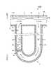
図1は、実施形態1の微細藻類培養装置を上方から視た平面図である。図2は、図1のII-II線矢視断面図である。図1、図2に示すように、微細藻類培養装置100は、培養液110を貯留する槽1と、水車6と、2つのU字配管10(図2で一方のU字配管10のみ図示)と、2つの散気装置20(図2で一方の散気装置20のみ図示)と、を備えている。(Embodiment 1)
FIG. 1 is a plan view of the microalgae culture apparatus of the first embodiment as viewed from above. FIG. 2 is a cross-sectional view taken along the line II-II of FIG. As shown in FIGS. 1 and 2, the
図1に示すように、槽1は、レースウェイ方式の槽である。具体的に、槽1は、水平方向に延在する底壁2と、環状の側壁3と、側壁3の中央部に設けられた仕切壁4と、を備えている。よって、槽1の内部は、培養液110が水平方向に流れ、かつ培養液110が仕切壁4を中心に循環する循環流路5となっている。 As shown in FIG. 1, the tank 1 is a raceway type tank. Specifically, the tank 1 includes a
水車6は、図示しないモータから動力が伝達されて回転している。これにより、培養液110は、循環流路5を図1に示す矢印の方に移動し、循環流路5を循環している。これにより、培養液中の微細藻類の分布が均一となる。また、培養液に溶解している二酸化炭素の濃度も均一となる。 The water turbine 6 rotates by transmitting power from a motor (not shown). As a result, the
図2に示すように、槽1は、循環流路5の上方を覆う天壁を有していない。つまり、槽1は、いわゆるオープンポンド(開放系)の槽である。よって、光合成により微細藻類から排出された酸素は、循環流路5から上方(系外)に排出される。 As shown in FIG. 2, the tank 1 does not have a top wall covering the upper part of the
槽1の底壁2は比較的浅い。これにより、循環流路5の下側に分布する微細藻類も太陽光を吸収し易くなる。また、槽1の底壁2には、2つの第1開口部7と、2つの第2開口部8と、が設けられている。 The
第1開口部7及び第2開口部8は、図1に示すように上方から視て四角形状となっているが、本開示においては、例えば円などの他の形状となっていてもよい。第1開口部7は、循環流路5からU字配管10へ培養液110を流入されるための孔である。第2開口部8は、U字配管10から循環流路5へ培養液110を流出させるための孔である。よって、第1開口部7と第2開口部8は、2つで一組である。 The
図1に示すように、一組の第1開口部7と第2開口部8と、別の組の第1開口部7と第2開口部8は、互いに離隔して配置されている。また、一組の第1開口部7と第2開口部8において、第2開口部8の方が第1開口部7よりも循環流路5の上流側に配置されている。 As shown in FIG. 1, one set of the first opening 7 and the second opening 8 and another set of the first opening 7 and the
図2に示すように、U字配管10は、第1配管11と、第2配管12と、を備えている。第1配管11及び第2配管12は、上下方向に延在している。第1配管11の上部は、第1開口部7に接続している。第2配管12の上部は、第2開口部8に接続している。第1配管11の下部と第2配管12の下部は、互いに屈曲し、互いに接続している。これにより、第1配管11の第1流路11aと第2配管12の第2流路12aとが連続し、U字状の流路となる。 As shown in FIG. 2, the U-shaped
散気装置20は、二酸化炭素を含む気体を培養液に供給する二酸化炭素供給装置である。なお、気体中の二酸化炭素濃度は、特に限定されない。散気装置20の供給口21から供給される気体は、培養液110中で気泡22となるが、溶解し易くするため、気泡22の径が例えば5mm以下であることが望ましい。また、散気装置20から培養液に供給される第2配管12の流路の断面積における気体量は、例えば2.0NL(ノルマルリットル)/cm2/min以下であることが好ましく、1.0NL(ノルマルリットル)/cm2/min以下となることがより好ましい。The
また、散気装置20から供給される気体は、化石燃料を燃焼させた際に発生する排気ガスであってもよい。排気ガスは、二酸化炭素を含んでいるため、大気中に放出する二酸化炭素の量を低減できる。また、排気ガス中に含まれる酸素の濃度は、10%以下となることが好ましい。 Further, the gas supplied from the
散気装置20の供給口21は、第2流路12aの下部に配置されている。つまり、第2流路12aの下部で微細な気泡22が生成されるようになっている。そして、生成された気泡22が上昇すると、第2流路12aの培養液110は、上向きの推進力を受ける。よって、第2流路12aの培養液110は、上昇して循環流路5へ流れる。一方で第1流路11aの培養液110は、第2流路12aの方に引き込まれる。よって、第1流路11aにおいては、培養液110が下向きに流れる。さらに、第1流路11aにおいて、培養液110が下方に流れるため、循環流路5を流れる培養液110の一部が第1流路11aに引き込まれる。これにより、第2流路12aから循環流路5に戻った培養液110の一部は、再びU字配管10内に引き込まれるようになっている。 The
供給口21から循環流路5の液面5aまでの距離Lは、1.5m以上、好ましくは1.5m以上6m未満、更に好ましくは1.5m以上2.5m未満、である。これによれば、気泡サイズ5mm以下の場合、二酸化炭素の溶解率が90%以上となり、効率的な溶解が可能となる。
The distance L from the
次に実施形態1の微細藻類培養装置100の効果について説明する。微細藻類培養装置100において、供給口21から循環流路5の液面5aまでの距離Lは、1.5m以上となっている。このため、気泡22が液面5aに到達するまでの距離が十分に確保されている。よって、培養液110に溶解する二酸化炭素の量は、従来と比べて格段に増加する。 Next, the effect of the
また、第1配管11及び第2配管12は、鉛直方向に対して傾斜していない。よって、上昇する気泡22が第2配管12の内周面に付着し難い。仮に気泡22が第2配管12の内周面に付着すると、気泡22同士が接触して径が大型化した気泡22が生成される。このような径が大きい気泡22は培養液110に溶解し難い。よって、本実施形態では、第2配管12は、鉛直方向に対して傾斜していないので、上昇する気泡22が第2配管12の内周面に付着することによる二酸化炭素の溶解率の低下、ということが回避されている。 Further, the
また、第2開口部8が第1開口部7に対し、循環流路5の上流側に配置されている。これにより、第2流路12aから循環流路5に戻った培養液110の一部は、再びU字配管10に引き込まれるため、培養液110中の二酸化炭素の濃度が高まる。 Further, the
以上、実施形態1の微細藻類培養装置100は、内部空間が微細藻類を含む培養液110の流路となっており、第1開口部7及び第2開口部8が設けられた槽1と、上下方向に延在し、上部が第1開口部7と接続する第1流路11aと、上下方向に延在し、上部が第2開口部8と接続し、下部が第1流路11aの下部とを接続する第2流路12aと、第2流路12aの下部に配置され、第2流路12aの培養液110に二酸化炭素を含む気体を供給口21から供給する散気装置20と、を備える。供給口21は、槽1の液面5aから下方に位置している。供給口21と液面5aとの距離Lは、1.5m以上である。 As described above, in the
実施形態1によれば、供給した二酸化炭素の多くが溶解する。よって、従来の微細藻類培養装置に比べて溶解率が高い。 According to the first embodiment, most of the supplied carbon dioxide is dissolved. Therefore, the dissolution rate is higher than that of the conventional microalgae culture apparatus.
また、実施形態1において、第1開口部7は、第2開口部8よりも、培養液110の流れの下流に配置されている。 Further, in the first embodiment, the
これによれば、培養液110の一部を繰り返しU字配管10に引き込み、培養液110中の二酸化炭素の濃度が高まる。 According to this, a part of the
以上、実施形態1について説明したが、本開示は、これに限定されない。例えば、実施形態1において、U字配管10及び散気装置20をそれぞれ2つ有しているが、本開示は、1つであってもよく、又は3つ以上有していてもよい。 Although the first embodiment has been described above, the present disclosure is not limited to this. For example, in the first embodiment, the
図3は、変形例1に係る配管を示す図である。また、実施形態1の第1配管11と第2配管の下端は、R状(円弧状)を成しているが、本開示は、第1配管11と第2配管の下端が直角に屈曲してもよく、特に限定されない。また、本開示は、第1配管11及び第2配管12のうち一方が直線状の配管であり、他方が直線状の配管の周りを周回する螺旋状(スパイラル)の配管であってもよい。また、本開示は、図3に示すように、第2配管12の上下方向の途中に第1配管11の下端が接続するようになっていてもよい。また、この変形例1において、散気装置20は、第2配管12内であって第1配管11が合流する部分よりも下方に配置されてもよい。 FIG. 3 is a diagram showing a pipe according to the first modification. Further, the lower ends of the
散気装置20による気体の供給は、連続的又は間欠的であってもよく、特に限定されない。 The supply of gas by the
また、本開示は、第1配管11及び第2配管12は鉛直方向に対して傾斜していてもよい。ただし、第2配管12が傾斜している場合、二酸化炭素の溶解率が落ちる。よって、実施形態1の例が好ましい状態である。 Further, in the present disclosure, the
また、実施形態1において、第1開口部7及び第2開口部8は、槽1の底壁2に設けられているが、本開示は、培養液110が流入できればよい。よって、第1開口部7及び第2開口部8の位置は、循環流路5を流れる培養液110の液面5aよりも下方であればよい。 Further, in the first embodiment, the
図4に示すように、第1開口部7の方が第2開口部8よりも循環流路5の上流側に配置されていてもよい。この変形例2の微細藻類培養装置100Aによれば、U字配管10から流出した培養液110がすぐにU字配管10に引き込まれる、ということがなくなる。 As shown in FIG. 4, the
(実施形態2)
図5は、実施形態2に係る微細藻類培養装置の一部拡大図である。次に実施形態2の微細藻類培養装置100Bは、図5に示すように、槽1に代えて槽1Bとなっている点で実施形態1と相違する。槽1Bは、光が透過可能な透明な管の一端と他端を接続した形状である。つまり、槽1Bは、循環流路5の上方を覆う天壁9を有しており、循環流路5の断面形状が環状となっている。(Embodiment 2)
FIG. 5 is a partially enlarged view of the microalgae culture apparatus according to the second embodiment. Next, the
このような微細藻類培養装置100Bによっても、実施形態1と同じように供給した二酸化炭素の多くが溶解する。また、これに伴い、循環流路5の上方に溜まる二酸化炭素の量が少なくなる。よって、槽1B内における気相のスペースM(図5参照)も小さくなる。仮に気相のスペースMが大きくなると、相対的に培養液110のスペースが小さくなり、培養液110の液量も低減してしまう。よって、実施形態2によれば、培養液111の液量が低減する、という不利益を回避できる。 Even with such a
(実施形態3)
図6は、実施形態3の微細藻類培養装置の全体図である。実施形態3の微細藻類培養装置100Cは、フォトバイオリアクタである。詳細には、図6に示すように、実施形態3の微細藻類培養装置100Cは、槽1に代えて槽1Cとなっている点で実施形態1と相違する。また、微細藻類培養装置100Cは、水車6に代えてポンプ6Cとなっている点で実施形態1と相違する。また、微細藻類培養装置100Cは、バッファタンク30とpH測定装置40と制御装置50を備える点で実施形態1と相違する。(Embodiment 3)
FIG. 6 is an overall view of the microalgae culture apparatus of the third embodiment. The
槽1Cは、水平方向に延びる複数の直線管60を複数の屈曲管61で繋ぎ合わせて、旋回しながら上下方向に培養液110を流す管である。直線管60及び屈曲管61は、光合成を可能とするため透明な材料から成る。なお、槽1Cは、槽1Cを支持する専用の支持台に支持されたり、建物において太陽光が一日中照射される壁面に固定されたりしてもよい。 The
実施形態3では、ポンプ6Cにより培養液110が上方に流れる。よって、槽1Cの流入口62は下側に位置し、流出口63は上方に位置している。槽1Cの流入口62は、下側接続管70を介して、バッファタンク30の下部に接続している。槽1Cの流出口63は、上側接続管71を介して、バッファタンク30の上部に接続している。 In the third embodiment, the
U字配管10は、上側接続管71に設けられている。よって、槽1Cからバッファタンク30に流れる培養液110に二酸化炭素を供給している。U字配管10は、上側接続管71と下側接続管70との間に配置される。よって、上側接続管71と下側接続管70との間のスペースを有効に活用している。 The
バッファタンク30は、一時的に培養液110を貯留している。バッファタンク30の上部には、ガス抜き穴31が設けられている。これにより、微細藻類から発生した酸素や散気装置20から供給されて溶解しなかった二酸化炭素や、排ガス中の窒素ガスなどが、ガス抜き穴31から排出される。 The
pH測定装置40は、培養液110中の水素イオン濃度を測定する装置である。pH測定装置40は、上側接続管71であってU字配管10よりも上流側に配置されている。制御装置50は、pH測定装置40の測定結果に基づいて、散気装置20から供給する気体の量を調整する装置である。これによれば、培養液110に供給される気体が適量となる。また、槽1Cに直接二酸化炭素を供給すると、気相のスペースが大きくなり、相対的に培養液110のスペースが小さくなる。よって、本実施形態においても、実施形態2と同様に、培養液111の液量が低減する、という不利益を回避できる。 The
以上、実施形態3について説明したが、本開示は、制御装置50を備えていなくてもよい。つまり、作業者がpH測定装置40の測定結果を確認し、作業者が散気装置20からの供給量を調整してもよい。なお、本実施形態の槽1Cにおいて、培養液110が上方に流れるようになっているが、本開示は下方に流れるようにしてもよく、特に限定はない。また、培養液110が槽1C内を下方へ流れる場合、U字配管10は、下側接続管70又は上側接続管71に接続してもよい。 Although the third embodiment has been described above, the present disclosure does not have to include the
また、実施形態3の微細藻類培養装置100Cは、pH測定装置40を備えているが、本開示は、pH測定装置40に代えて培養液110に溶解する二酸化炭素の濃度を測定する二酸化炭素濃度測定装置を備える。そして、制御装置50は、二酸化炭素濃度測定装置の測定結果に基づいて、散気装置20から供給する気体の量を調整するようにしてもよい。若しくは、pH測定装置40と二酸化炭素濃度測定装置の両方を備えていてもよい。このような場合、制御装置50は、pH測定装置40の測定結果と二酸化炭素濃度測定装置の測定結果に基づいて、散気装置20から供給する気体の量を調整する。 Further, although the
1、1B、1C 槽
6 水車
6C ポンプ
5 循環流路
7 第1開口部
8 第2開口部
10 U字配管
11 第1配管
12 第2配管
11a 第1流路
12a 第2流路
20 散気装置
21 供給口
22 気泡
30 バッファタンク
31 ガス抜き穴
40 pH測定装置
50 制御装置
60 直線管
61 屈曲管
70 下側接続管
71 上側接続管
100、100A、100B、100C 微細藻類培養装置
110 培養液1, 1B, 1C tank 6
Claims (5)
Translated fromJapanese上下方向に延在し、上部が前記第1開口部と接続する第1流路と、
上下方向に延在し、上部が前記第2開口部と接続し、下部が前記第1流路の下部とを接続する第2流路と、
前記第2流路の下部に配置され、前記第2流路の前記培養液に二酸化炭素を含む気体を供給口から供給する散気装置と、
を備え、
前記槽は、
光が透過可能であり、内部を流れる前記培養液が光合成可能な管と、
前記光合成可能な管の流出口に接続する接続管と、
を少なくとも備え、
前記第1開口部及び前記第2開口部は、前記接続管に設けられ、
前記供給口は、前記槽の液面から下方に位置し、
前記供給口と前記液面との距離は、1.5m以上であり、
前記第2開口部は、前記第1開口部よりも、前記光合成可能な管の前記流出口寄りに配置されている
微細藻類培養装置。The internal space serves as a circulation channel for the culture solution containing microalgae, and a tank provided with a first opening and a second opening, and a tank.
A first flow path extending in the vertical direction and having an upper portion connected to the first opening,
A second flow path that extends in the vertical direction, the upper part of which connects to the second opening, and the lower part of which connects to the lower part of the first flow path.
An air diffuser arranged in the lower part of the second flow path and supplying a gas containing carbon dioxide to the culture solution in the second flow path from a supply port.
With
The tank is
A tube through which light can pass and the culture solution flowing inside can be photosynthesized.
A connecting tube connected to the outlet of the photosynthetic tube,
At least
The first opening and the second opening are provided in the connecting pipe.
The supply port is located below the liquid level of the tank and is located below.
The distance between the supply port and the liquid level is 1.5 m or more.
Thesecond opening is a microalgae culturing device arrangedcloser to the outlet of the photosynthetic tube than thefirst opening.
前記pH測定装置の測定結果に基づいて、前記散気装置から供給する気体の量を調整する制御装置と、
を備え、
前記pH測定装置は、前記第2開口部よりも、前記光合成可能な管の前記流出口寄りに配置されている
請求項1に記載の微細藻類培養装置。A pH measuring device for measuring the pH value of the culture solution and
A control device that adjusts the amount of gas supplied from the air diffuser based on the measurement results of the pH measuring device, and
With
The microalgae culturing device according to claim 1, wherein the pH measuring device is arrangedcloser to the outlet of the photosynthetic tube than thesecond opening.
前記二酸化炭素濃度測定装置の測定結果に基づいて、前記散気装置から供給する気体の量を調整する制御装置と、
を備え、
前記二酸化炭素濃度測定装置は、前記第2開口部よりも、前記光合成可能な管の前記流出口寄りに配置されている
請求項1に記載の微細藻類培養装置。A carbon dioxide concentration measuring device for measuring the concentration of the carbon dioxide dissolved in the culture solution, and
A control device that adjusts the amount of gas supplied from the air diffuser based on the measurement results of the carbon dioxide concentration measuring device, and
With
The microalgae cultivating device according to claim 1, wherein the carbon dioxide concentration measuring device is arrangedcloser to the outlet of the photosynthetic tube than thesecond opening.
前記培養液に溶解する前記二酸化炭素の濃度を測定する二酸化炭素濃度測定装置と、
前記pH測定装置の測定結果と前記二酸化炭素濃度測定装置の測定結果に基づいて、前記散気装置から供給する気体の量を調整する制御装置と、
を備え、
前記pH測定装置及び前記二酸化炭素濃度測定装置は、前記第2開口部よりも、前記光合成可能な管の前記流出口寄りに配置されている
請求項1に記載の微細藻類培養装置。A pH measuring device for measuring the pH value of the culture solution and
A carbon dioxide concentration measuring device for measuring the concentration of the carbon dioxide dissolved in the culture solution, and
A control device that adjusts the amount of gas supplied from the air diffuser based on the measurement result of the pH measuring device and the measurement result of the carbon dioxide concentration measuring device.
With
The microalgae cultivating device according to claim 1, wherein the pH measuring device and the carbon dioxide concentration measuring device are arrangedcloser to the outlet of the photosynthetic tube than thesecond opening.
前記排気ガスは、二酸化炭素と酸素を含み、かつ前記排気ガス中の酸素の濃度が10%以下となっている
請求項1から請求項4のいずれか1項に記載の微細藻類培養装置。
The gas supplied from the air diffuser is an exhaust gas generated by combustion of fossil fuel.
The microalgae cultivating apparatus according to any one of claims 1 to 4, wherein the exhaust gas contains carbon dioxide and oxygen, and the concentration of oxygen in the exhaust gas is 10% or less.
Priority Applications (2)
| Application Number | Priority Date | Filing Date | Title |
|---|---|---|---|
| JP2021180352AJP7102597B1 (en) | 2021-11-04 | 2021-11-04 | Microalgae culture equipment |
| MYPI2022006186AMY199287A (en) | 2021-11-04 | 2022-11-03 | Microalgae cultivation device |
Applications Claiming Priority (1)
| Application Number | Priority Date | Filing Date | Title |
|---|---|---|---|
| JP2021180352AJP7102597B1 (en) | 2021-11-04 | 2021-11-04 | Microalgae culture equipment |
Publications (2)
| Publication Number | Publication Date |
|---|---|
| JP7102597B1true JP7102597B1 (en) | 2022-07-19 |
| JP2023068902A JP2023068902A (en) | 2023-05-18 |
Family
ID=82457389
Family Applications (1)
| Application Number | Title | Priority Date | Filing Date |
|---|---|---|---|
| JP2021180352AActiveJP7102597B1 (en) | 2021-11-04 | 2021-11-04 | Microalgae culture equipment |
Country Status (2)
| Country | Link |
|---|---|
| JP (1) | JP7102597B1 (en) |
| MY (1) | MY199287A (en) |
Citations (12)
| Publication number | Priority date | Publication date | Assignee | Title |
|---|---|---|---|---|
| CN101659922A (en) | 2008-08-28 | 2010-03-03 | 青岛生物能源与过程研究所 | Closed raceway pond microalgae culture system |
| CN101948740A (en) | 2010-09-10 | 2011-01-19 | 中国科学院过程工程研究所 | Small-fall open pond for massively cultivating microalgae as well as use method and application thereof |
| JP2011239746A (en) | 2010-05-20 | 2011-12-01 | Sumitomo Heavy Ind Ltd | Photosynthesis microalgae culture apparatus |
| JP2012023978A (en) | 2010-07-20 | 2012-02-09 | Hitachi Plant Technologies Ltd | Apparatus and method for culturing photosynthetic microorganism |
| US20140042085A1 (en) | 2012-07-19 | 2014-02-13 | Aquanos Energy Ltd. | Systems and methods for waste treatment |
| US20140242681A1 (en) | 2013-02-28 | 2014-08-28 | Julian Fiorentino | Photobioreactor |
| JP2017079602A (en) | 2015-10-23 | 2017-05-18 | 株式会社デンソー | Apparatus and method for culturing photosynthetic microorganism |
| US20180195032A1 (en) | 2015-07-01 | 2018-07-12 | Nelson Mandela University | Microalgae production process and equipment |
| US20190218490A1 (en) | 2016-08-30 | 2019-07-18 | Ecoduna Ag | Photobioreactor and method for the cultivating of microalgae |
| JP2020065992A (en) | 2018-10-26 | 2020-04-30 | 臼井国際産業株式会社 | Gas dissolution device and algae culturing device |
| CN111704990A (en) | 2020-07-13 | 2020-09-25 | 浙江大学 | Tube-pool combined flash bioreactor system and method for microalgae growth and carbon fixation |
| CN212102842U (en) | 2020-03-16 | 2020-12-08 | 贵州民族大学 | A closed transparent runway pool for cultivating microalgae |
Family Cites Families (3)
| Publication number | Priority date | Publication date | Assignee | Title |
|---|---|---|---|---|
| US4253271A (en)* | 1978-12-28 | 1981-03-03 | Battelle Memorial Institute | Mass algal culture system |
| JP3085393B2 (en)* | 1990-08-03 | 2000-09-04 | 株式会社日立製作所 | Culture method and culture apparatus for photosynthetic organisms |
| US8458952B1 (en)* | 2010-06-11 | 2013-06-11 | Independence Bio-Products, Inc. | Method and system for harvesting micro organisms |
- 2021
- 2021-11-04JPJP2021180352Apatent/JP7102597B1/enactiveActive
- 2022
- 2022-11-03MYMYPI2022006186Apatent/MY199287A/enunknown
Patent Citations (12)
| Publication number | Priority date | Publication date | Assignee | Title |
|---|---|---|---|---|
| CN101659922A (en) | 2008-08-28 | 2010-03-03 | 青岛生物能源与过程研究所 | Closed raceway pond microalgae culture system |
| JP2011239746A (en) | 2010-05-20 | 2011-12-01 | Sumitomo Heavy Ind Ltd | Photosynthesis microalgae culture apparatus |
| JP2012023978A (en) | 2010-07-20 | 2012-02-09 | Hitachi Plant Technologies Ltd | Apparatus and method for culturing photosynthetic microorganism |
| CN101948740A (en) | 2010-09-10 | 2011-01-19 | 中国科学院过程工程研究所 | Small-fall open pond for massively cultivating microalgae as well as use method and application thereof |
| US20140042085A1 (en) | 2012-07-19 | 2014-02-13 | Aquanos Energy Ltd. | Systems and methods for waste treatment |
| US20140242681A1 (en) | 2013-02-28 | 2014-08-28 | Julian Fiorentino | Photobioreactor |
| US20180195032A1 (en) | 2015-07-01 | 2018-07-12 | Nelson Mandela University | Microalgae production process and equipment |
| JP2017079602A (en) | 2015-10-23 | 2017-05-18 | 株式会社デンソー | Apparatus and method for culturing photosynthetic microorganism |
| US20190218490A1 (en) | 2016-08-30 | 2019-07-18 | Ecoduna Ag | Photobioreactor and method for the cultivating of microalgae |
| JP2020065992A (en) | 2018-10-26 | 2020-04-30 | 臼井国際産業株式会社 | Gas dissolution device and algae culturing device |
| CN212102842U (en) | 2020-03-16 | 2020-12-08 | 贵州民族大学 | A closed transparent runway pool for cultivating microalgae |
| CN111704990A (en) | 2020-07-13 | 2020-09-25 | 浙江大学 | Tube-pool combined flash bioreactor system and method for microalgae growth and carbon fixation |
Non-Patent Citations (4)
| Title |
|---|
| A. Jacob et al.,Applued Energy,2015年04月04日,Vol. 148,p. 396-402 |
| A. Janoska et al.,Algal Research,2018年11月01日,Vol. 36,p. 193-208 |
| C. M. Kuo et al.,Bioresource Technology,2018年06月28日,Vol. 266,p. 398-406 |
| Raquel Dormido et al.,Sensors,2014年03月06日,Vol. 14,p. 4466-4483 |
Also Published As
| Publication number | Publication date |
|---|---|
| MY199287A (en) | 2023-10-24 |
| JP2023068902A (en) | 2023-05-18 |
Similar Documents
| Publication | Publication Date | Title |
|---|---|---|
| US8476067B2 (en) | Photobioreactor and method for processing polluted air | |
| JP5992451B2 (en) | Method and bioreactor for culturing microorganisms | |
| US20070155006A1 (en) | Photobioreactor | |
| US9175252B2 (en) | Photobioreactor and method for processing polluted air | |
| KR101043583B1 (en) | Photobioreactor having a dispersion plate in which the internal light source is integrated for high microalgae culture | |
| JP2007061086A (en) | Photosynthesis reactor for plant algae/microorganism | |
| WO2020085366A1 (en) | Gas dissolving device and algae cultivation device | |
| KR20130123043A (en) | Closed type of photo-bio reacting apparatus | |
| JP7102597B1 (en) | Microalgae culture equipment | |
| CN106367313A (en) | Flat plate photobioreactor | |
| JP2013039044A (en) | Living thing raising device | |
| JPS62220183A (en) | Culture device for fine alga | |
| US11795421B2 (en) | Microalgae production process and equipment | |
| CN201339027Y (en) | Dissolved oxygen tower for fermentation | |
| JP5892744B2 (en) | Gas dissolution apparatus, biological growth apparatus, and gas dissolution method | |
| EP2712917A1 (en) | Carbonation system for cultivating microalgae in open reactors | |
| US20120107452A1 (en) | Aeration systems for horizontal photobioreactors | |
| JP2615394B2 (en) | Culture stirring method and culture apparatus | |
| CN217868677U (en) | Airlift microbial fertilizer fermentation tank | |
| JP4389500B2 (en) | Bioreactor | |
| JP7554227B2 (en) | Culture method and culture device | |
| CN205999377U (en) | The gas-liquid mixed mass transfer photo bio stacked rectangular capsules device being easily enlarged | |
| KR102302999B1 (en) | Water stream apparatus for preventing from algae generation | |
| JP2025123709A (en) | Microalgae manufacturing method and microalgae manufacturing device | |
| JP2025123942A (en) | Microalgae manufacturing method and microalgae manufacturing device |
Legal Events
| Date | Code | Title | Description |
|---|---|---|---|
| A621 | Written request for application examination | Free format text:JAPANESE INTERMEDIATE CODE: A621 Effective date:20211104 | |
| A871 | Explanation of circumstances concerning accelerated examination | Free format text:JAPANESE INTERMEDIATE CODE: A871 Effective date:20211104 | |
| A131 | Notification of reasons for refusal | Free format text:JAPANESE INTERMEDIATE CODE: A131 Effective date:20211214 | |
| A521 | Request for written amendment filed | Free format text:JAPANESE INTERMEDIATE CODE: A523 Effective date:20220209 | |
| A131 | Notification of reasons for refusal | Free format text:JAPANESE INTERMEDIATE CODE: A131 Effective date:20220322 | |
| A521 | Request for written amendment filed | Free format text:JAPANESE INTERMEDIATE CODE: A523 Effective date:20220519 | |
| TRDD | Decision of grant or rejection written | ||
| A01 | Written decision to grant a patent or to grant a registration (utility model) | Free format text:JAPANESE INTERMEDIATE CODE: A01 Effective date:20220614 | |
| A61 | First payment of annual fees (during grant procedure) | Free format text:JAPANESE INTERMEDIATE CODE: A61 Effective date:20220706 | |
| R150 | Certificate of patent or registration of utility model | Ref document number:7102597 Country of ref document:JP Free format text:JAPANESE INTERMEDIATE CODE: R150 | |
| R250 | Receipt of annual fees | Free format text:JAPANESE INTERMEDIATE CODE: R250 |