JP7101199B2 - Container and latching system - Google Patents
Container and latching systemDownload PDFInfo
- Publication number
- JP7101199B2 JP7101199B2JP2019566933AJP2019566933AJP7101199B2JP 7101199 B2JP7101199 B2JP 7101199B2JP 2019566933 AJP2019566933 AJP 2019566933AJP 2019566933 AJP2019566933 AJP 2019566933AJP 7101199 B2JP7101199 B2JP 7101199B2
- Authority
- JP
- Japan
- Prior art keywords
- container
- lid
- locking member
- latch
- base
- Prior art date
- Legal status (The legal status is an assumption and is not a legal conclusion. Google has not performed a legal analysis and makes no representation as to the accuracy of the status listed.)
- Active
Links
Images


Classifications
- B—PERFORMING OPERATIONS; TRANSPORTING
- B65—CONVEYING; PACKING; STORING; HANDLING THIN OR FILAMENTARY MATERIAL
- B65D—CONTAINERS FOR STORAGE OR TRANSPORT OF ARTICLES OR MATERIALS, e.g. BAGS, BARRELS, BOTTLES, BOXES, CANS, CARTONS, CRATES, DRUMS, JARS, TANKS, HOPPERS, FORWARDING CONTAINERS; ACCESSORIES, CLOSURES, OR FITTINGS THEREFOR; PACKAGING ELEMENTS; PACKAGES
- B65D43/00—Lids or covers for rigid or semi-rigid containers
- B65D43/14—Non-removable lids or covers
- B65D43/16—Non-removable lids or covers hinged for upward or downward movement
- B65D43/163—Non-removable lids or covers hinged for upward or downward movement the container and the lid being made separately
- B65D43/164—Non-removable lids or covers hinged for upward or downward movement the container and the lid being made separately and connected by interfitting hinge elements integrally with the container and the lid formed respectively
- B65D43/165—Non-removable lids or covers hinged for upward or downward movement the container and the lid being made separately and connected by interfitting hinge elements integrally with the container and the lid formed respectively these elements being assembled by a separate pin-like member
- B—PERFORMING OPERATIONS; TRANSPORTING
- B65—CONVEYING; PACKING; STORING; HANDLING THIN OR FILAMENTARY MATERIAL
- B65D—CONTAINERS FOR STORAGE OR TRANSPORT OF ARTICLES OR MATERIALS, e.g. BAGS, BARRELS, BOTTLES, BOXES, CANS, CARTONS, CRATES, DRUMS, JARS, TANKS, HOPPERS, FORWARDING CONTAINERS; ACCESSORIES, CLOSURES, OR FITTINGS THEREFOR; PACKAGING ELEMENTS; PACKAGES
- B65D25/00—Details of other kinds or types of rigid or semi-rigid containers
- B65D25/28—Handles
- B65D25/2835—Swingable handles
- B65D25/2838—Swingable handles provided on a local area of the side wall(s)
- B65D25/2841—Horizontal, e.g. U-shaped
- B—PERFORMING OPERATIONS; TRANSPORTING
- B65—CONVEYING; PACKING; STORING; HANDLING THIN OR FILAMENTARY MATERIAL
- B65D—CONTAINERS FOR STORAGE OR TRANSPORT OF ARTICLES OR MATERIALS, e.g. BAGS, BARRELS, BOTTLES, BOXES, CANS, CARTONS, CRATES, DRUMS, JARS, TANKS, HOPPERS, FORWARDING CONTAINERS; ACCESSORIES, CLOSURES, OR FITTINGS THEREFOR; PACKAGING ELEMENTS; PACKAGES
- B65D43/00—Lids or covers for rigid or semi-rigid containers
- B65D43/14—Non-removable lids or covers
- B65D43/16—Non-removable lids or covers hinged for upward or downward movement
- B—PERFORMING OPERATIONS; TRANSPORTING
- B65—CONVEYING; PACKING; STORING; HANDLING THIN OR FILAMENTARY MATERIAL
- B65D—CONTAINERS FOR STORAGE OR TRANSPORT OF ARTICLES OR MATERIALS, e.g. BAGS, BARRELS, BOTTLES, BOXES, CANS, CARTONS, CRATES, DRUMS, JARS, TANKS, HOPPERS, FORWARDING CONTAINERS; ACCESSORIES, CLOSURES, OR FITTINGS THEREFOR; PACKAGING ELEMENTS; PACKAGES
- B65D43/00—Lids or covers for rigid or semi-rigid containers
- B65D43/14—Non-removable lids or covers
- B65D43/22—Devices for holding in closed position, e.g. clips
- B—PERFORMING OPERATIONS; TRANSPORTING
- B65—CONVEYING; PACKING; STORING; HANDLING THIN OR FILAMENTARY MATERIAL
- B65D—CONTAINERS FOR STORAGE OR TRANSPORT OF ARTICLES OR MATERIALS, e.g. BAGS, BARRELS, BOTTLES, BOXES, CANS, CARTONS, CRATES, DRUMS, JARS, TANKS, HOPPERS, FORWARDING CONTAINERS; ACCESSORIES, CLOSURES, OR FITTINGS THEREFOR; PACKAGING ELEMENTS; PACKAGES
- B65D45/00—Clamping or other pressure-applying devices for securing or retaining closure members
- B65D45/02—Clamping or other pressure-applying devices for securing or retaining closure members for applying axial pressure to engage closure with sealing surface
- B65D45/16—Clips, hooks, or clamps which are removable, or which remain connected either with the closure or with the container when the container is open, e.g. C-shaped
- B65D45/20—Clips, hooks, or clamps which are removable, or which remain connected either with the closure or with the container when the container is open, e.g. C-shaped pivoted
- B65D45/24—Clips, hooks, or clamps which are removable, or which remain connected either with the closure or with the container when the container is open, e.g. C-shaped pivoted incorporating pressure-applying means, e.g. screws or toggles
- E—FIXED CONSTRUCTIONS
- E05—LOCKS; KEYS; WINDOW OR DOOR FITTINGS; SAFES
- E05B—LOCKS; ACCESSORIES THEREFOR; HANDCUFFS
- E05B65/00—Locks or fastenings for special use
- E05B65/52—Other locks for chests, boxes, trunks, baskets, travelling bags, or the like
- E—FIXED CONSTRUCTIONS
- E05—LOCKS; KEYS; WINDOW OR DOOR FITTINGS; SAFES
- E05B—LOCKS; ACCESSORIES THEREFOR; HANDCUFFS
- E05B65/00—Locks or fastenings for special use
- E05B65/52—Other locks for chests, boxes, trunks, baskets, travelling bags, or the like
- E05B65/5207—Other locks for chests, boxes, trunks, baskets, travelling bags, or the like characterised by bolt movement
- E—FIXED CONSTRUCTIONS
- E05—LOCKS; KEYS; WINDOW OR DOOR FITTINGS; SAFES
- E05C—BOLTS OR FASTENING DEVICES FOR WINGS, SPECIALLY FOR DOORS OR WINDOWS
- E05C5/00—Fastening devices with bolts moving otherwise than only rectilinearly and only pivotally or rotatively
Landscapes
- Engineering & Computer Science (AREA)
- Mechanical Engineering (AREA)
- Closures For Containers (AREA)
- Details Of Rigid Or Semi-Rigid Containers (AREA)
- Supplying Of Containers To The Packaging Station (AREA)
- Purses, Travelling Bags, Baskets, Or Suitcases (AREA)
- Refuse Receptacles (AREA)
Description
Translated fromJapanese 関連出願との相互参照
本出願は、2018年6月12日に出願された米国非仮特許出願第16/006,344号明細書、および、2017年6月12日に出願された米国仮特許出願第62/518,358号明細書の優先権を主張する。上記に参照された出願は、その全体が参照により組み込まれている。Mutual reference with related applications This application is a US non-provisional patent application No. 16 / 006,344 filed on June 12, 2018, and a US provisional patent filed on June 12, 2017. Claim the priority of Application No. 62 / 518,358. The applications referenced above are incorporated by reference in their entirety.
さまざまなタイプのコンテナおよびラッチング・システムが存在している。コンテナは、食料、飲料、および他の材料、またはアイテムのために使用され得る。ラッチング・システムは、コンテナを閉構成にロックするために存在している。しかし、従来のコンテナおよびラッチング・システムは、あまり耐久性がないことが多く、使用しやすくない可能性がある。たとえば、コンテナは、特定のアイテムを保持するには十分に強力ではない可能性があり、コンテナの上にアイテムを保持するのに十分に強力ではない可能性がある。追加的に、いくつかのラッチング・システムは、システムが係合されることをユーザーが希望しないときに係合する可能性があり、他のケースでは、コンテナのために十分なロックを提供しない可能性がある。そのような配置では、これらのおよび他の欠点は、コンテナおよび/またはラッチング・システムを事実上役に立たないものにする可能性がある。 There are different types of containers and latching systems. Containers can be used for food, beverages, and other ingredients, or items. Latching systems exist to lock the container to a closed configuration. However, traditional container and latching systems are often not very durable and may not be easy to use. For example, a container may not be strong enough to hold a particular item and may not be strong enough to hold an item on top of the container. In addition, some latching systems may engage when the user does not want the system to be engaged, and in other cases may not provide sufficient lock for the container. There is sex. In such an arrangement, these and other drawbacks can make the container and / or latching system virtually useless.
本概要は、簡単化された形態で概念の選択を導入するために提供されており、それらは、詳細な説明においてさらに下記に説明されている。本概要は、特許請求されている主題の重要な特徴または本質的な特徴を識別することは意図しておらず、また、特許請求されている主題の範囲を限定するために使用されることも意図していない。 This overview is provided to introduce a selection of concepts in a simplified form, which are further described below in the detailed description. This overview is not intended to identify the material or essential features of the claimed subject matter and may also be used to limit the scope of the claimed subject matter. Not intended.
1つの態様によれば、コンテナが開示されている。コンテナは、成形されたベースを含むことが可能であり、成形されたベースは、側壁部構造体であって、側壁部構造体は、第1の側部と、第1の側部の反対側の第2の側部と、第1の側部の縁部と第2の側部の縁部との間に延在する第3の側部と、第3の側部の反対側の第4の側部とを有しており、側壁部構造体は、第1の端部および第2の端部を有している、側壁部構造体と;側壁部構造体の第1の端部に接続されている底部部分であって、底部部分は、表面の上にコンテナを支持するように構成されている、底部部分と;第1の端部の反対側に、側壁部構造体の第2の端部に形成された開口部であって、開口部は、側壁部構造体および底部部分によって形成されたコンテナの内部空洞へのアクセスを可能にするように構成されている、開口部とを含む。ベースは、側壁部構造体から延在するラッチ・キーパーをさらに含むことが可能であり、ラッチ・キーパーは、上側表面、内側表面、および下側表面を有している。また、コンテナは、蓋部を含むことが可能であり、蓋部は、開構成と閉構成との間で枢動可能であり、蓋部は、ベースの形状に対応する形状を有しており、コンテナが閉構成にあるときに、側壁部構造体の第2の端部に形成された開口部をカバーするように構成されている。ヒンジは、蓋部をベースに接続するように構成され得り、蓋部は、閉構成から開構成へ回転可能である。コンテナは、ラッチ・アッセンブリをさらに含むことが可能であり、ラッチ・アッセンブリは、ロック位置およびアンロック位置を有している。 According to one aspect, the container is disclosed. The container can include a molded base, the molded base being a side wall structure, the side wall structure being the first side and the opposite side of the first side. The second side of the, the third side extending between the edge of the first side and the edge of the second side, and the fourth on the opposite side of the third side. The side wall structure has a first end and a second end, with the side wall structure; at the first end of the side wall structure. A connected bottom portion, the bottom portion of which is configured to support the container over the surface; with the bottom portion; on the opposite side of the first end, a second of the sidewall structures. An opening formed at the end of the container, wherein the opening is configured to allow access to the internal cavity of the container formed by the sidewall structure and the bottom portion. include. The base can further include a latch keeper extending from the sidewall structure, the latch keeper having an upper surface, an inner surface, and a lower surface. Also, the container can include a lid, the lid is pivotable between the open and closed configurations, and the lid has a shape that corresponds to the shape of the base. It is configured to cover an opening formed at the second end of the side wall structure when the container is in a closed configuration. The hinge may be configured to connect the lid to the base, which is rotatable from a closed configuration to an open configuration. The container can further include a latch assembly, which has a locking and unlocking position.
ラッチ・アッセンブリは、ラッチ本体部を含むことが可能であり、ラッチ本体部は、蓋部と枢動可能に係合されており、ラッチ本体部は、少なくとも1つの係合ラグを有している。ラッチ・アッセンブリは、ロッキング部材をさらに含むことが可能であり、ロッキング部材は、ラッチ本体部とスライド可能に係合されており、ロッキング部材は、少なくとも下方位置と上方位置との間でスライド可能である。ロッキング部材は、ロッキング部材が下方位置にあるときには、蓋部を閉構成にロックするように構成され得り、ロッキング部材が上方位置にあるときには、蓋部をアンロックするように構成され得る。さらに、ラッチ・アッセンブリは、ラッチ本体部およびロッキング部材と係合されている付勢部材であって、付勢部材は、ロッキング部材を下方位置に付勢する、付勢部材と;活性化部材であって、活性化部材は、ラッチ本体部と枢動可能に係合されており、また、ロッキング部材と係合されており、活性化部材は、下方位置から上方位置へロッキング部材を移動させるように構成されている、活性化部材とをさらに含む。ラッチ・アッセンブリは、ロッキング部材が上方位置にあるときにのみ、アンロック位置からロック位置へ移動させられ得る。ラッチ・アッセンブリの別の態様は、ラッチ本体部の少なくとも1つの係合ラグは、ラッチ・アッセンブリがロック位置にあるときに、ラッチ・キーパーの下側表面に係合させられ得るということ、および、ロッキング部材のフック部分は、ラッチ・アッセンブリがロック位置にあるときに、ラッチ・キーパーの上側表面に係合することが可能であるということである。 The latch assembly can include a latch body, the latch body is pivotally engaged with the lid, and the latch body has at least one engagement lug. .. The latch assembly can further include a locking member, the locking member is slidably engaged with the latch body, and the locking member is slidable at least between the lower and upper positions. be. The locking member may be configured to lock the lid in a closed configuration when the locking member is in the lower position and may be configured to unlock the lid when the locking member is in the upper position. Further, the latch assembly is an urging member that is engaged with the latch main body and the locking member, and the urging member is an urging member that urges the locking member to a lower position; an activation member. The activating member is pivotally engaged with the latch body and is also engaged with the locking member so that the activating member moves the locking member from the lower position to the upper position. Further includes an activation member, which is configured in. The latch assembly can only be moved from the unlocked position to the locked position when the locking member is in the upper position. Another aspect of the latch assembly is that at least one engaging lug on the latch body can be engaged to the underside surface of the latch keeper when the latch assembly is in the locked position. The hook portion of the locking member is capable of engaging the upper surface of the latch keeper when the latch assembly is in the locked position.
本開示の他の態様は、コンテナの蓋部が閉構成から開構成へ回転させられるということは、蓋部を閉構成から90度回転させることを含むことが可能であるということに関することが可能である。加えて、ラッチ・キーパーは、サポート・リブをさらに含むことが可能であり、サポート・リブは、ベースの外部表面からラッチ・キーパーの内側表面へ延在しており、サポート・リブは、ラッチ・キーパーの上側表面に対して中央に位置付けされ得る。ロッキング部材は、少なくとも2つのフック部分をさらに含むことが可能であり、ラッチ・アッセンブリがロック位置にあるときには、サポート・リブが、ロッキング部材の少なくとも2つのフック部分の間に位置決めされるようになっている。ベースは、ラッチ・キーパーに隣接して少なくとも1つのランプ付きの表面を含むことが可能であり、ランプ付きの表面が、ベースのインターフェース表面から離れるように所定の角度で下向きに延在するようになっている。少なくとも1つのランプ付きの表面は、ベースのインターフェース表面に対して、30度から60度の間の角度を形成している。ガスケットが、ベースおよび蓋部のうちの少なくとも1つの中に形成された凹部の中に配置され得る。別の特徴として、ベースは、コンテナの側部のそれぞれの上にハンドルをさらに含むことが可能であり、それぞれのハンドルは、ベースと一体的に成形されている。ハンドルは、ハンドルの外部表面の下に、湾曲したプロファイルを有することが可能であり、湾曲したプロファイルは、側壁部構造体の側部のうちの1つからハンドルの内部表面へ延在する複数のリブによって形成されている。 Another aspect of the present disclosure is that the fact that the lid of the container is rotated from the closed configuration to the open configuration can include rotating the lid 90 degrees from the closed configuration. Is. In addition, the latch keeper can further include support ribs, the support ribs extend from the outer surface of the base to the inner surface of the latch keeper, and the support ribs are latch keeper. It can be centered on the upper surface of the keeper. The locking member can further include at least two hook portions so that the support ribs are positioned between the at least two hook portions of the locking member when the latch assembly is in the locked position. ing. The base can include at least one surface with a ramp adjacent to the latch keeper so that the surface with the ramp extends downward at a predetermined angle away from the interface surface of the base. It has become. The surface with at least one lamp forms an angle between 30 and 60 degrees with respect to the interface surface of the base. The gasket may be placed in a recess formed in at least one of the base and the lid. As another feature, the base can further include handles on top of each of the sides of the container, each handle being integrally molded with the base. The handle can have a curved profile underneath the outer surface of the handle, the curved profile extending from one of the sides of the sidewall structure to the inner surface of the handle. It is formed by ribs.
本開示の他の態様は、コンテナに関することが可能であり、コンテナは、であって、側壁部構造体であって、側壁部構造体は、少なくとも、第1の側部と、第1の側部の反対側の第2の側部とを有しており、側壁部構造体は、第1の端部および第2の端部を有している、側壁部構造体と;側壁部構造体の第1の端部に接続されている底部部分であって、底部部分は、表面の上にコンテナを支持するように構成されている、底部部分と;第1の端部の反対側に、側壁部構造体の第2の端部に形成された開口部であって、開口部は、側壁部構造体および底部部分によって形成されたコンテナの内部空洞へのアクセスを可能にするように構成されている、開口部とを含む。また、ベースは、側壁部構造体から延在するラッチ・キーパーを含むことが可能であり、ラッチ・キーパーは、上側表面、内側表面、および下側表面を有している。また、コンテナは、蓋部を含むことが可能であり、蓋部は、開構成と閉構成との間で枢動可能であり、蓋部は、ベースの形状に対応する形状を有しており、コンテナが閉構成にあるときに、側壁部構造体の第2の端部に形成された開口部をカバーするように構成されている。ヒンジは、蓋部をベースに接続するように構成され得り、ヒンジの周りで、蓋部は、閉構成から開構成へ回転可能であり、ラッチ・アッセンブリは、ロック位置およびアンロック位置を有している。ラッチ・アッセンブリは、蓋部と枢動可能に係合されているラッチ本体部であって、ラッチ本体部は、少なくとも1つの係合ラグを有している、ラッチ本体部と;ラッチ本体部と係合されているロッキング部材であって、ロッキング部材は、下方位置と上方位置との間で移動可能である、ロッキング部材とを含むことが可能である。ロッキング部材は、ロッキング部材が下方位置にあるときには、蓋部を閉構成にロックするように構成され得り、ロッキング部材が上方位置にあるときには、蓋部をアンロックするように構成され得る。また、ラッチ・アッセンブリは、ラッチ本体部およびロッキング部材と係合されている付勢部材であって、付勢部材は、ロッキング部材を下方位置に付勢する、付勢部材と;活性化部材であって、活性化部材は、ラッチ本体部と枢動可能に係合されており、また、ロッキング部材と係合されており、活性化部材は、下方位置から上方位置へロッキング部材を移動させるように構成されている、活性化部材とを有することが可能である。 Another aspect of the present disclosure can be about a container, wherein the container is a side wall structure, wherein the side wall structure is at least a first side and a first side. With a side wall structure having a second side opposite to the portion and having a first end and a second end; the side wall structure. A bottom portion connected to the first end of the, the bottom portion of which is configured to support the container over the surface, with the bottom portion; on the opposite side of the first end. An opening formed at the second end of the side wall structure, the opening being configured to allow access to the internal cavity of the container formed by the side wall structure and the bottom portion. Includes openings and openings. The base can also include a latch keeper extending from the sidewall structure, the latch keeper having an upper surface, an inner surface, and a lower surface. Also, the container can include a lid, the lid is pivotable between the open and closed configurations, and the lid has a shape that corresponds to the shape of the base. It is configured to cover an opening formed at the second end of the side wall structure when the container is in a closed configuration. The hinge can be configured to connect the lid to the base, around the hinge the lid is rotatable from closed to open configuration, and the latch assembly has a locking and unlocking position. is doing. The latch assembly is a latch body that is pivotally engaged with the lid, the latch body having at least one engaging lug, with the latch body; with the latch body. The locking member that is engaged can include a locking member that is movable between a lower position and an upper position. The locking member may be configured to lock the lid in a closed configuration when the locking member is in the lower position and may be configured to unlock the lid when the locking member is in the upper position. Further, the latch assembly is an urging member engaged with the latch main body and the locking member, and the urging member is an urging member that urges the locking member to a lower position; an activation member. The activating member is pivotally engaged with the latch body and is also engaged with the locking member so that the activating member moves the locking member from the lower position to the upper position. It is possible to have an activating member configured in.
本開示の追加的な態様は、コンテナのベース部分に関することが可能であり、ベース部分は、内部空洞の内部表面に沿って位置決めされている複数のタブを含む。複数のタブのそれぞれのタブは、内部表面のうちの1つから延在することが可能であり、上側サポート表面および開口部を含み、それぞれのタブの開口部は、細長い形状を有している。上側サポート表面は、ベースの内部空洞の上側領域の中に位置付けされ得り、または、内部空洞の高さの50パーセントより大きい高さに位置決めされ得る。加えて、ベースは、1対のトラックを含むことが可能であり、1対のトラックは、少なくとも1つの側壁部の少なくとも内部表面の上に位置決めされており、1対のトラックは、少なくとも2つの側壁部の少なくとも内部表面の上に位置決めされている。同様に、蓋部は、蓋部の内部表面に沿って位置決めされている複数のクリップを含むことが可能であり、それぞれのクリップは、係合部材および細長い開口部を含み、複数のタブのそれぞれのタブの細長い開口部は、それぞれのクリップの細長い開口部と実質的に同じ幅を有することが可能である。また、コンテナは、ガスケットと、ベースの外部表面と一体的に成形されたチャネルとを有することが可能であり、ガスケットは、ベースおよび蓋部のうちの少なくとも1つの中に形成された凹部の中に配置されており、チャネルは、ベースの外部表面全体の周りに延在している。 An additional aspect of the present disclosure may be with respect to the base portion of the container, the base portion comprising a plurality of tabs positioned along the inner surface of the internal cavity. Each tab of the plurality of tabs can extend from one of the inner surfaces, including the upper support surface and openings, and the openings of each tab have an elongated shape. .. The upper support surface can be positioned within the upper region of the inner cavity of the base or can be positioned at a height greater than 50 percent of the height of the inner cavity. In addition, the base can include a pair of tracks, the pair of tracks being positioned on at least the inner surface of at least one side wall, and the pair of tracks being at least two. It is positioned on at least the inner surface of the side wall. Similarly, the lid can include multiple clips that are positioned along the internal surface of the lid, each clip containing an engaging member and an elongated opening, each of a plurality of tabs. The elongated openings in the tabs can have substantially the same width as the elongated openings in each clip. The container can also have a gasket and a channel integrally molded with the outer surface of the base, the gasket being in a recess formed in at least one of the base and the lid. Arranged in, the channels extend around the entire outer surface of the base.
本示のさらなる他の態様は、コンテナに関することが可能であり、コンテナは、ベースを含み、ベースは、側壁部構造体であって、側壁部構造体は、少なくとも、第1の側部と、第1の側部の反対側の第2の側部とを有しており、側壁部構造体は、第1の端部および第2の端部を備えている、側壁部構造体と;側壁部構造体の第1の端部に接続されている底部部分であって、底部部分は、表面の上にコンテナを支持するように構成されている、底部部分と;第1の端部の反対側に、側壁部構造体の第2の端部に形成された開口部であって、開口部は、側壁部構造体および底部部分によって形成されたコンテナの内部空洞へのアクセスを可能にする、開口部とを有している。また、コンテナは、蓋部を有することが可能であり、蓋部は、開構成と閉構成との間で枢動可能であり、蓋部は、ベースの形状に対応する形状を有しており、コンテナが閉構成にあるときに、側壁部構造体の第2の端部に形成された開口部をカバーするように構成されている。また、コンテナは、ラッチ・アッセンブリを含むことが可能であり、ラッチ・アッセンブリは、ロック位置およびアンロック位置を有しており、ラッチ・アッセンブリは、蓋部と枢動可能に係合されているラッチ本体部と、ラッチ本体部と係合されているロッキング部材とを含み、ロッキング部材は、下方位置と上方位置との間で移動可能である。ロッキング部材は、ロッキング部材が下方位置にあるときには、蓋部を閉構成にロックするように構成されており、ロッキング部材が上方位置にあるときには、蓋部をアンロックするように構成されている。活性化部材は、ラッチ本体部と枢動可能に係合され得り、また、ロッキング部材と係合され得り、活性化部材は、下方位置から上方位置へロッキング部材を移動させる。 Yet another aspect of the present invention may relate to a container, wherein the container comprises a base, the base being a side wall structure, the side wall structure being at least the first side portion, and the like. With a side wall structure having a second side opposite to the first side and having a side wall structure with a first end and a second end; The bottom portion connected to the first end of the structure, the bottom portion being configured to support the container over the surface; the opposite of the first end. On the side, an opening formed at the second end of the sidewall structure, which allows access to the internal cavity of the container formed by the sidewall structure and the bottom portion. It has an opening. Also, the container can have a lid, the lid is pivotable between the open and closed configurations, and the lid has a shape that corresponds to the shape of the base. It is configured to cover an opening formed at the second end of the side wall structure when the container is in a closed configuration. The container can also include a latch assembly, the latch assembly has a locking and unlocking position, and the latch assembly is pivotally engaged with the lid. The locking member includes a latch body and a locking member engaged with the latch body, the locking member being movable between a lower position and an upper position. The locking member is configured to lock the lid to the closed configuration when the locking member is in the lower position, and to unlock the lid when the locking member is in the upper position. The activating member may be pivotally engaged with the latch body and may also be pivotally engaged with the locking member, the activating member moving the locking member from a lower position to an upper position.
本開示の中に説明されているコンテナの他の態様は、ラッチ・アッセンブリを含むことが可能であり、ラッチ・アッセンブリは、ラッチ本体部およびロッキング部材と係合されている付勢部材を有しており、付勢部材は、ロッキング部材を下方位置に付勢する。ロッキング部材は、下方位置と上方位置との間でスライド可能であり得り、ラッチ・アッセンブリは、ロッキング部材が上方位置にあるときにのみ、アンロック位置からロック位置へ移動させられ得る。ラッチ本体部は、内側表面および少なくとも1つの係合ラグを含むことが可能であり、ベースは、ラッチ・キーパーを含み、ラッチ・キーパーは、上側表面、内側表面、および下側表面を含む。ラッチ本体部の少なくとも1つの係合ラグは、ラッチ・アッセンブリがロック位置にあるときに、ラッチ・キーパーの下側表面に係合することが可能であり、ロッキング部材のフック部分の下側表面は、ラッチ・アッセンブリがロック位置にあるときに、ラッチ・キーパーの上側表面に係合している。 Other aspects of the container described in the present disclosure may include a latch assembly, which has a latch body and an urging member engaged with a locking member. The urging member urges the locking member to a lower position. The locking member may be slidable between the lower and upper positions, and the latch assembly may be moved from the unlocked position to the locked position only when the locking member is in the upper position. The latch body can include an inner surface and at least one engaging lug, the base includes a latch keeper, and the latch keeper includes an upper surface, an inner surface, and a lower surface. At least one engaging lug on the latch body can engage the underside surface of the latch keeper when the latch assembly is in the locked position, and the underside surface of the hook portion of the locking member , Engages the upper surface of the latch keeper when the latch assembly is in the locked position.
この概要は、簡単化された形態で概念の選択を導入するために提供されており、それは、詳細な説明の中でさらに下記に説明されている。本概要は、特許請求されている主題の重要な特徴または本質的な特徴を識別することは意図しておらず、また、特許請求されている主題の範囲を限定するために使用されることも意図していない。 This overview is provided to introduce the selection of concepts in a simplified form, which is further explained below in the detailed description. This overview is not intended to identify the material or essential features of the claimed subject matter and may also be used to limit the scope of the claimed subject matter. Not intended.
本発明は、例として図示されており、添付の図の中で限定されていない。添付の図において、同様の参照番号は、同様のエレメントを示している。 The present invention is illustrated as an example and is not limited in the accompanying figures. In the attached figure, similar reference numbers indicate similar elements.
さらに、図面は、単一の実施形態の異なるコンポーネントのスケールを表している可能性があるが、しかし、開示されている実施形態は、その特定のスケールに限定されないということが理解されるべきである。 Further, it should be understood that the drawings may represent the scale of different components of a single embodiment, but the disclosed embodiments are not limited to that particular scale. be.
本発明によるさまざまな例示的な構造体の以下の説明において、添付の図面が参照されており、図面は、説明の一部を形成しており、図面には、本発明の態様が実践され得るさまざまな例示的なデバイス、システム、および環境が、図示として示されている。他のパーツの特定の配置、例示的なデバイス、システム、および環境が利用され得り、構造的なおよび機能的な修正が、本発明の範囲から逸脱することなく行われ得るということが理解されるべきである。また、「上部」、「底部」、「正面」、「裏面」、「サイド」、および「後方」などのような用語は、本発明のさまざまな例示的な特徴およびエレメントを説明するために、この明細書の中で使用されている可能性があるが、これらの用語は、たとえば、図に示されている例示的な配向、または、典型的な使用の間の配向に基づいて、便宜上、本明細書において使用されている。追加的に、本明細書で使用されているように、「複数の」という用語は、論理和的または論理積的のいずれかで、必要に応じて、無限数までの1つよりも大きい任意の数を示している。本明細書の中のいずれも、本発明の範囲の中に入るために、構造体の特定の3次元の配向を必要とするものとして解釈されるべきではない。また、読者は、添付された図面は必ずしも正しい縮尺で描かれているわけではないということを知らされる。 In the following description of the various exemplary structures according to the invention, the accompanying drawings are referred to, the drawings form part of the description, in which the embodiments of the invention may be practiced. Various exemplary devices, systems, and environments are shown as illustrations. It is understood that specific arrangements of other parts, exemplary devices, systems, and environments may be utilized and structural and functional modifications may be made without departing from the scope of the invention. Should be. Also, terms such as "top," "bottom," "front," "back," "side," and "rear" are used to describe various exemplary features and elements of the invention. As may be used herein, these terms are used for convenience, for convenience, based on, for example, the exemplary orientation shown in the figure, or the orientation between typical uses. As used herein. Additionally, as used herein, the term "plurality" is either logically or ANDed, and optionally greater than one, up to an infinite number. Shows the number of. None of this specification should be construed as requiring a particular three-dimensional orientation of the structure to fall within the scope of the invention. Readers will also be informed that the attached drawings are not always drawn to the correct scale.
一般的に、本発明の態様は、コンテナ、および、コンテナのためのラッチング・アッセンブリに関する。さまざまな態様および実施形態によれば、本明細書で説明されているコンテナおよびラッチング・アッセンブリは、金属(金属合金を含む)、ポリマー、および複合材などのような、さまざまな材料のうちの1つまたは複数から形成され得り、本発明の範囲を逸脱することなく、さまざまな構成のうちの1の中に形成され得る。コンテナおよびラッチング・アッセンブリは、いくつかの異なる材料から作製されたコンポーネントを含有することが可能であるということが理解される。追加的に、コンポーネントは、さまざまな形成方法によって形成され得る。たとえば、金属コンポーネントは、フォージング、成形、キャスティング、スタンピング、機械加工、および/または、他の公知の技法によって形成され得る。追加的に、エラストマーなどのようなポリマー・コンポーネントは、さまざまな成形およびキャスティング技法などのようなポリマー加工技法、ならびに/または他の公知の技法によって製造され得る。 In general, aspects of the invention relate to containers and latching assemblies for containers. According to various embodiments and embodiments, the containers and latching assemblies described herein are one of a variety of materials, such as metals (including metal alloys), polymers, and composites. It can be formed from one or more, and can be formed in one of a variety of configurations without departing from the scope of the invention. It is understood that containers and latching assemblies can contain components made from several different materials. Additionally, components can be formed by a variety of forming methods. For example, metal components can be formed by forging, forming, casting, stamping, machining, and / or other known techniques. Additionally, polymer components such as elastomers can be manufactured by polymer processing techniques such as various molding and casting techniques, and / or other known techniques.
本願の中のさまざまな図は、本発明によるコンテナおよびラッチング・アッセンブリの例を図示している。同じ参照数字が2つ以上の図面の中に出現するときには、その参照数字は、この明細書の中で一貫して使用されており、図面は、全体を通して同じまたは同様のパーツを表している。 The various figures in this application illustrate examples of containers and latching assemblies according to the present invention. When the same reference number appears in more than one drawing, the reference number is used consistently herein and the drawing represents the same or similar parts throughout.
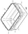
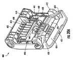
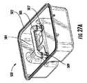
図1A、図1B、および図2Aは、コンテナ2の斜視図を示している。1つの例では、コンテナ2は、ベース部分4および蓋部5を含むことが可能であり、蓋部5は、いくつかの例では、ベース部分4に連結され得り、または、いくつかの例では、ベース部分4に非破壊的に除去可能に連結され得る。ベース部分4は、本明細書でより完全に議論されることとなるように、物品を含有するための空洞を形成する構造体であることが可能である。いくつかの例では、ベース部分4は、形状が立方体状または実質的に立方体状になっていることが可能である。他の例では、ベース部分4は、形状が角柱状または実質的に角柱状(たとえば、五角柱、六角柱、または七角柱など)になっていることが可能である。さらに他の例では、ベース部分4は、形状が実質的に円筒形状になっているか、または、実質的に台形の断面を有することが可能である。さまざまな他の形状が、本発明から逸脱することなく使用され得る。 1A, 1B, and 2A show perspective views of
ベース部分4は、側壁部構造体6を含むことが可能であり、側壁部構造体6は、第1の側部8と、第1の側部の反対側の第2の側部10と、第1の側部の縁部と第2の側部の縁部との間に延在する第3の側部12と、第3の側部の反対側の第4の側部14とを有している。また、側壁部構造体6は、第1の端部16および第2の端部18を有することが可能である。また、側壁部構造体6は、底部部分20を含むことが可能であり、底部部分20は、側壁部構造体6の第1の端部16に接続されており、テーブル、地面、または車両ベッドなどのような、表面の上にコンテナを支持するように構成されている。いくつかの実施形態では、底部部分20は、また、および/または代替的に、1つまたは複数の足部22を含むことが可能であり、1つまたは複数の足部22は、テーブル、地面、または車両ベッドなどのような、表面の上にコンテナ2を支持することが可能である。足部22は、ベース4と一体的に形成され得るか、または、ベースが形成された後に、ベース4に取り付けられ得る。 The
ベース部分4は、開口部19(図3に示されている)を画定する第2の端部18をさらに含む。開口部19は、側壁部構造体6および底部部分20によって形成されたコンテナ2の内部空洞21へのアクセスを可能にするように構成されている。 The
コンテナ2は、蓋部5を含むことが可能である。蓋部5は、開構成と閉構成との間で枢動可能である。いくつかの実施形態では、閉構成から開構成へ蓋部を回転させることは、閉構成から約90°、または、閉構成から約180°、または、閉構成から約270°、蓋部を回転させることを含む。図1に示されているように、開口部19は、コンテナが使用中であるときに(たとえば、コンテナが閉構成になっているときに)、蓋部5によってカバーされ得る。いくつかの配置では、蓋部5は、圧入を使用して、閉構成において、ベース4に接続することが可能である。追加的に、または代替的に、他の固定システムまたはデバイスが、本明細書でより完全に議論されることとなるように、蓋部5をベース4に固定するために使用され得る。 The
いくつかの例では、蓋部5は、それが(除去可能にまたは恒久的にのいずれかで)ヒンジ37においてベース4に接続されるようにヒンジ接続され得り、ヒンジ37の周りに回転させられ得る。ヒンジ37は、連続的なピアノ・ヒンジ、ダブル・ヒンジ、ボール・ジョイント・ヒンジ、およびリビング・ヒンジなどを含む、さまざまなタイプのヒンジのうちの1つであることが可能である。これらのおよびさまざまな他のヒンジ配置は、本明細書でさらに完全に議論され得る。ヒンジ37は、蓋部5がベース部分4から離れるように開けられおよび回転させられることを許容し、ベース部分4によって画定された空洞へのアクセス(たとえば、開口部19を介して)を可能にすることができる。すなわち、ヒンジ37は、コンテナの閉構成(たとえば、図1Aに示されているように、蓋部が、ベース4によって形成された空洞21をカバーする場所にあるとき)から開構成(たとえば、図1Bに示されているように、蓋部が、ベース4によって形成された空洞21をカバーしていないとき)への蓋部5の回転を促進させることが可能であり、また、その逆も同様である。 In some examples, the
加えて、いくつかの配置では、コンテナ2は、ガスケット30または他のシーリング・デバイスを含むことが可能である。ガスケット30は、蓋部5またはベース4にいずれかの中に配置され得り、蓋部5が閉構成になっているときに、蓋部5およびベース4をシールすることを支援することが可能である。たとえば、1つの実施形態では、コンテナ2は、8時間にわたってテストされたときに、それが防塵性であるように、および/または、水深1メートルにおいて、30分にわたってテストされたときに、耐水性であるように製造され得る。いくつかの実施形態では、コンテナ2は、(国際電気標準会議に記述されているような)IP67レーティングを実現することができる可能性があり、IP67レーティングは、8時間にわたってテストされたときに、ダストの侵入が存在しないこと、または、ダストからの完全な保護が存在することを特定しており、ならびに、圧力および時間の定義された条件の下でエンクロージャーが水の中に浸漬されているときに(最大で1mの水没)、有害な量での水の侵入が可能でないということを特定している。IP67ダスト・テストは、8時間の長さにわたり、エンクロージャーが、真空でテストされる。IP67水テストは、30分の長さにわたり、エンクロージャーは、エンクロージャーの最低点が水の表面から1000mm下方にある状態、または、最高点が表面から150mmから下方にある状態のうちのいずれか深い方でテストされる。 In addition, in some arrangements, the
いくつかの例では(および、図10A~図11Cに最良に示されているように)、ガスケット30は、ベース4および蓋部5のうちの少なくとも1つの中に形成された凹部32の中に着座され得り、ベース4または蓋部5のうちの少なくとも1つの周囲部の周りに延在している。追加的に、いくつかの例では、コンテナ2は、ベース4または蓋部5の反対側にリッジ部34を含むことが可能であり、リッジ部34は、ベース4または蓋部5の周囲部の周りに延在している。ガスケット30が、凹部32とリッジ部34との間に設置され得る。ガスケット30は、コンテナ2の内部と外側の環境との間にシールを維持することを支援することが可能であり、いくつかの例では、コンテナ2の中に含有されている物品の温度を維持することを支援することが可能である。1つの例示的なガスケット配置が、図10A~図11Cに示されているが、このおよびさまざまな他のガスケット配置も、本明細書で説明されているコンテナのいずれかとともに使用され得る。 In some examples (and best shown in FIGS. 10A-11C), the
示されているように、ガスケット30は、蓋部5の中の凹部またはチャネル32の中に配置されている。代替的に、ガスケット30は、ベース4の中に形成された凹部またはチャネルの中に配置され得る。蓋部5が閉構成になっているときには、凹部32に対応する形状を有するリッジ部34が、ガスケット30に接触し、ガスケット30を圧縮し、蓋部5およびベース4を閉構成にシールすることを支援することが可能である。いくつかの例では、ガスケット30は、実質的に円形の断面を有する従来のガスケットであることが可能である。他の配置では、ガスケット30は、戦略的に設置されたカットアウトを含むことが可能であり、カットアウトは、ベント(たとえば、蓋部ロックを防止するためのベント)の必要性を低減させるかまたは排除することが可能である。 As shown, the
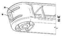
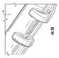
いくつかの配置では、コンテナ2は、1つまたは複数のハンドル40などのような追加的な特徴を含むことが可能である。ハンドルは、示されているように、側部12および14などのような対向する側部を含む、側壁部構造体6の1つまたは複数の部分の上に配置され得る。図4A~図4Dに最良に示されているように、ハンドル40は、グリッピング部材46によって接続されている第1および第2のアーム42、44から構築され得る。ハンドル40は、ヒンジ43の周りに枢動可能であり得り、ヒンジ43は、側壁部構造体6の一部分を通過し、また、第1および第2のアーム42、44のそれぞれを通過している。また、ハンドル40は、ハンドルが使用されていないときのハンドルの移動(および、それに関連付けられるガタガタと鳴る騒音の可能性)を低減させるための特徴を含むことが可能である。図4A~図4Dに示されているように、アーム42、44のうちの一方または両方は、アームの遠位端部において、隆起部分48を含むことが可能である。いくつかの実施形態では、隆起部分48は、弾性部材50に取り付けられ得る。図4Aおよび図4Dに最良に示されているように、コンテナ2は、凹んだ部分52を含むことが可能である。隆起部分48は、ハンドル40が使用されていないときに、側壁部構造体6の凹んだ部分52の中に位置付けされるように構成され得る。これは、ハンドルが使用されていないときのハンドル40の移動を低減させることが可能である。しかし、ユーザーが使用のためにハンドル40を移動させるときには、弾性部材50は、後退することが可能であり、ユーザーがハンドルを外向きに回転させることを可能にすることができる。 In some arrangements, the
他の例では、図14~図16Bに示されているように、および、より詳細に下記に議論されることとなるように、ハンドル240は、ベース部分204と一体的に成形され得り、いくつかの例では、一般的に、ベース204の側壁部構造体の中に形成されたアンダーカットであることが可能である。いくつかの例では、ハンドルを形成するアンダーカットは、側壁部構造体6の実質的にすべてまたは大部分に沿って延在する凹部を含むことが可能である。これは、一体的に成形されたハンドル240を備えたベース204の製造のしやすさを提供することが可能である。いくつかの例では、一体的に成形されたハンドル240は、破損のリスクを低減させるために、ベース204の外部表面と同一平面になっていることが可能である。 In another example, the
いくつかの配置では、コンテナ2は、また、1つまたは複数のラッチ・アッセンブリ100を含むことが可能である。ラッチ・アッセンブリ100は、ロック位置およびアンロック位置を有することが可能であり、蓋部5が閉構成になっているときに、蓋部5をロックするように構成され得る。ラッチ・アッセンブリ100は、コンテナ2と一体的に形成されているかまたはその他の方法で取り付けられている1つまたは複数の部分を含むことが可能である。図5Bおよび図9に示されているように、コンテナ2は、ラッチ・キーパー70を含むことが可能である。ラッチ・キーパー70は、側壁部構造体6から延在することが可能であり、コンテナ2の中にポケットを形成することが可能である。ラッチ・キーパー70ポケットは、より詳細に下記に議論されることとなるようなロッキング部材130の一部分を受け入れるように構成された形状を有している。ラッチ・キーパーは、上側表面72、内側表面74、および下側表面76を有することが可能である。より詳細に下記に議論されることとなるように、ラッチ・アッセンブリ100は、ラッチ・キーパー70に係合することが可能であり、コンテナ2が閉構成になっているときに、蓋部5をベース4にロックする。 In some arrangements, the
また、コンテナ2は、コンテナ2の強度および/または機能性を改善するために、さまざまな特徴を含むことが可能である。たとえば、コンテナは、さまざまな隆起部分を含むことが可能であり、ベース4および/または蓋部5の特定の部分は、ベース4および/または蓋部の他のパーツよりも遠くへ外向きに延在している。図1A、図1B、図2A、および図2Bに最良に示されているように、ベース4は、チャネル60を形成するJ字形状の隆起部分または壁部59を含むことが可能であり、隆起した壁部59は、側壁部構造体6と係合されている。チャネル60は、コンテナ2の周囲部全体を取り囲むことが可能である。また、チャネル60は、チャネルの中のさまざまな場所において、補強部材62を含むことが可能である。J字形状の壁部59によって形成されたチャネル60は、コンテナ2またはベース4の強度を増加させることが可能である。いくつかの実施形態では、および、たとえば、図2Bに示されているように、J字形状の壁部59は、側壁部構造体6の内部表面6Aがコンテナ2の内部部分の全体を通して実質的に滑らかになるように、ベース4が構築されることを可能にすることができる。したがって、たとえば、側壁部構造体6の内部表面6Aの実質的にすべてまたはすべては(第1の側部8、第1の側部の反対側の第2の側部10、第3の側部12のうちの1つまたはすべてを含む)、実質的に平坦であり、および/または、滑らかであることが可能である。 Also, the
また、コンテナ2は、ラッチング・アッセンブリ100およびハンドル40をそれぞれ取り囲む隆起部分64、66を含むことが可能である。図4に示されているように、隆起部分64、66は、ベース4または蓋部5のうちの一方または両方の上に存在することが可能である。隆起部分64、66は、それぞれ、ラッチング・アッセンブリ100およびハンドル40の高さに等しいかまたはそれよりも大きく隆起していることが可能であり、そのラッチング・アッセンブリ100および/またはハンドル40が、コンテナ2の隆起部分64、66を越えて外向きに延在しないようになっている。これは、ラッチング・アッセンブリ100および/またはハンドル40を保護し、および使用の間のこれらのコンポーネントの破損を低減させることが可能である。 Also, the
コンテナ2は、食料、飲料を含むアイテム、または、任意の他のアイテムを含有、貯蔵、運搬などするように構成され得る。追加的にまたは代替的に、コンテナ2は、本明細書で説明されている開示の範囲から逸脱することなく、固体状態もしくは気体状態の材料、または、それらの組み合わせを貯蔵するように構成され得る。 The
ベース4および蓋部5を含むコンテナ2は、1つまたは複数の金属、合金、ポリマー、セラミック、または繊維強化材料などのような、さまざまな材料から形成され得る。いくつかの例では、ベース4および蓋部5は、ポリエチレンなどのようなプラスチック材料から形成され得り、それは、ベース4部分および蓋部5部分の両方を形成するように成形される。いくつかの配置では、ベース4部分および蓋部5部分の外側シェルは、当業者によって理解されることとなるように、射出成形またはロト・モールディング/回転成形プロセスを使用して形成され得る(図示せず)。しかし、さまざまな他のタイプの成形、または、他の製造プロセス(たとえば、スタンピング、キャスティング、およびフォージングなど)が、本発明から逸脱することなく、コンテナ2を形成するために使用され得る。 The
本明細書のいくつかの配置では、ベース4および蓋部5は、断熱部分(図示せず)を取り囲むおよび囲む外部表面または外側シェルを含むことが可能であり、したがって、断熱コンテナを形成する。外側シェルは、典型的に、1つまたは複数の金属、合金、ポリマー、セラミック、または繊維強化材料などのような、さまざまな材料から形成され得る。いくつかの例では、外側シェルは、ポリエチレンなどのようなプラスチック材料から形成され得り、それは、ベース4部分および蓋部5部分の両方を形成するように成形される。いくつかの例では、断熱部分(図示せず)は、低熱伝導率を示す断熱材料から形成され得る。たとえば、断熱部分は、ポリウレタン・フォームなどのようなポリマー・フォームから形成され得る(または、それを充填され得る)。追加的なまたは他の断熱材料が、本発明から逸脱することなく使用され得り、それは、たとえば、真空断熱式パネルを含む。いくつかの配置では、ベース4部分および蓋部5部分の外側シェルは、当業者によって理解されることとなることとなるように、射出成形またはロト・モールディング/回転成形プロセスを使用して形成され得る(図示せず)。しかし、さまざまな他のタイプの成形、または、他の製造プロセス(たとえば、スタンピング、キャスティング、およびフォージングなど)が、本発明から逸脱することなく、コンテナを形成するために使用され得る。 In some arrangements herein, the
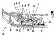
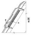
ここで、より具体的にラッチ・アッセンブリ100を参照すると、図8および図9に最良に示されているように、ラッチ・アッセンブリ100は、ラッチ本体部102、ロッキング部材130、付勢部材150、および活性化部材170を含む、複数のコンポーネントを含むことが可能である。上記に議論されているように、ラッチ・アッセンブリ100は、ロック位置およびアンロック位置を含むことが可能である。 Here, referring more specifically to the
ラッチ本体部102は、蓋部5と枢動可能に係合され得る。図9に示されているように、ラッチ本体部は、ヒンジ106を使用して蓋部5と枢動可能に係合され得るが、しかし、任意の適切な枢動係合が使用され得る。いくつかの実施形態では、ヒンジ106は、コンテナ2と除去可能に係合され得る。このヒンジ106は、ラッチ・アッセンブリ100が損傷を受けた場合に、ユーザーがラッチ・アッセンブリ100を容易に除去および交換することを可能にすることができる。ラッチ本体部102は、内側表面108および外側表面110を含むことが可能である。外側表面は、湾曲していることが可能であり、一般的に、コンテナ2の側壁部構造体6の湾曲に従うことが可能である。上記に議論されているように、ラッチ本体部102の外側表面110は、いくつかの例では、コンテナ2の側壁部構造体6の外側縁部の外向きに延在しなくてもよい。また、内側表面108は、湾曲していることが可能であり、また、複数の異なる特徴を含むことが可能である。ラッチ本体部102の上に含まれ得る1つの例示的な特徴は、1つまたは複数の係合ラグ112であることが可能である。より詳細に下記に議論されることとなるように、係合ラグ112は、コンテナ・ベース4またはラッチ・キーパー70に係合することが可能であり、また、コンテナ2のベース4に対抗して蓋部5を圧縮することを支援することが可能である。 The
また、ラッチ本体部102は、ロッキング部材130と係合され得る。図8に示されているように、ロッキング部材130は、ラッチ本体部102とスライド可能に係合され得り、ロッキング部材130が、上方位置と下方位置との間で実質的に線形の経路で移動することができるようになっている。ロッキング部材130は、ロッキング部材130が下方位置にあるときには、蓋部5を閉構成にロックし、ロッキング部材130が上方位置にあるときには、蓋部5をアンロックするように構成され得る。 Further, the latch
主に図8示されているように、ロッキング部材130は、1つまたは複数のガイド部材132と移動可能に係合され得り、ロッキング部材130がガイド部材132を上下にスライドさせることができるようになっている。1つの実施形態では、ロッキング部材130は、ロッキング部材130を通過するアパーチャー134を含むことが可能であり、また、ガイド部材132は、アパーチャー134を通過することが可能である。ガイド部材132は、上部端部136において、および、底部端部138において、ラッチ本体部102と係合され得る。図8に示されているように、ガイド部材132は、円筒形状のロッドであるが、ロッキング部材130の上向きおよび下向きの移動を許容する任意の適切な形状も使用され得る。たとえば、ガイド部材132は、形状が角柱状または実質的に角柱状(たとえば、五角柱、六角柱、または七角柱など)であることが可能である。さらなる他の例では、ラッチング・アッセンブリ100は、ロッキング部材130とラッチ本体部102との間の概して線形の移動を可能にするのに適切な他のデバイス(たとえば、レールを含む)を含むことが可能である。 Primarily as shown in FIG. 8, the locking
図8に示されているように、ラッチ・アッセンブリ100は、また、少なくとも1つの付勢部材150を含むことが可能であり、少なくとも1つの付勢部材150は、ラッチ本体部102およびロッキング部材130と係合されている。より詳細に下記に議論されることとなるように、付勢部材150は、ロッキング部材130を下方位置に付勢するように構成されている。付勢部材150は、図8に示されているような圧縮スプリングであることが可能であるが、代替的な実施形態では、ロッキング部材130を下方位置に付勢するための任意の適切なデバイスであることが可能である。 As shown in FIG. 8, the
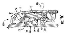
ロッキング部材130は、ベース部分140およびフック部分142を含むことが可能であり、フック部分142は、ベース部分140から内向きに延在している。フック部分142は、下側表面144および内向きに面する表面146を含むことが可能である。図9に示されているように、ラッチ・アッセンブリ100がロック位置にあるときには、ロッキング部材130のフック部分142の下側表面144は、ラッチ・キーパー70の上側表面72に係合することが可能であり、フック部分142の内向きに面する表面146は、ラッチ・キーパー70の内側表面74に係合することが可能である。追加的に、ラッチ・アッセンブリ100がロック位置にあるときには、係合ラグ112の上側表面は、ラッチ・キーパー70の下側表面76に係合することが可能である。 The locking
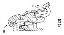
また、ラッチ本体部102は、活性化部材170と枢動可能に係合され得る。また、活性化部材170は、ロッキング部材130と係合され得り、ロッキング部材130を下方位置から上方位置へ移動させるように構成され得る。図8および図9に示されているように、活性化部材170はヒンジ172によってラッチ本体部102に枢動可能に係合され得り、ヒンジ172は、ラッチ本体部102および活性化部材170を通って延在している。活性化部材170は、グリップ部分174と、活性化バレル176と、グリップ部分174および活性化バレル176を接続する1つまたは複数のアーム178とを含むことが可能である。図9に示されているように、グリップ部分174は、コンテナ2の側壁部構造体6から所定の距離を置いて配置されている。この距離は、ユーザーが、彼らの指が側壁部構造体6とグリップ部分174との間に設置された状態で、グリップ部分174のバック表面180をグリップすることを可能にすることができる。図9に示されているように、活性化部材170の活性化バレル176は、ロッキング部材130に係合することが可能である。活性化バレル176は、隆起部分182を含むことが可能である。より詳細に下記に議論されることとなるように、ユーザーは、活性化部材170のグリップ部分174を前方に引っ張り、活性化バレル176の隆起部分182が回転してロッキング部材130を持ち上げることを引き起こすことが可能である。この移動は、ラッチ・アッセンブリ100がアンロックすることを引き起こし、蓋部5が閉構成から開構成へ移動させられることを可能にする。 Further, the latch
ここで図10A~図10Dを参照すると、ラッチ・アッセンブリ100の実施形態をロック位置からアンロック位置へ移動させるための手順が、ラッチ・アッセンブリ100、ならびに、ベース4および蓋部5の部分の側断面図によって示されている。図10Aは、ロック位置にあるラッチ・アッセンブリ100を示しており、図10Bは、アンロックしているラッチ・アッセンブリ100を示しており、図10Cは、アンロック位置にあるラッチ・アッセンブリ100を示しており、図10Dは、アンロック位置にあるラッチ・アッセンブリ100を示しており、回転防止特徴を実証している。図10Aに示されているように、ロック位置において、フック部分142の下側表面144は、ラッチ・キーパー70の上側表面72と係合されており、フック部分142の内向きに面する表面146は、ラッチ・キーパー70の内側表面74と係合されており、係合ラグ112は、ラッチ・キーパー70の下側表面76と係合されている。 Here, referring to FIGS. 10A to 10D, the procedure for moving the embodiment of the
図10Bに示されているように、ラッチング・アッセンブリ100は、矢印190によって示されているように活性化部材170を回転させることによって、アンロック位置へ移動させられ得る。この回転は、ユーザーがバック表面180を前方に引っ張ることによって達成され得る。図10Bに示されているように、活性化バレル176が回転するにつれて、隆起部分182が、ロッキング部材130に係合し、ロッキング部材130を上昇させる。図10Cに示されているように、ラッチング・アッセンブリ100は、アンロック位置になっている。ロッキング部材130がラッチ・キーパー70の上方に上昇すると、ラッチ・アッセンブリ100はされアンロックされ、ラッチ本体部102(ロッキング部材130および活性化部材170を含む)は、矢印194によって示されているように、前方に回転することが可能である。 As shown in FIG. 10B, the latching
図10Dは、ラッチ・アッセンブリ100の回転防止特徴およびコンテナ2を示している。図10Dに示されているように、ラッチ・アッセンブリ100は、アンロック位置にあり、図10Cに示されている位置からさらに外向きに回転させられている。ラッチ・アッセンブリ100の回転を制限するために、ラッチ本体部102は、バック表面187を含むことが可能であり、バック表面187は、ユーザーがラッチ・アッセンブリ100をロック位置から離れるように特定の回転だけ回転させると、蓋部の回転防止表面7に係合するように構成されている。たとえば、ユーザーが、ロック位置から少なくとも20度、または、ロック位置から少なくとも30度、または、ロック位置から少なくとも45度、または、ロック位置から少なくとも90度、ラッチ・アッセンブリ100を回転させたときに、バック表面187は、回転防止表面7に係合するように構成され得る。有利には、この回転防止特徴は、また、コンテナ2を開けるためのハンドルとしてユーザーがラッチ・アッセンブリ100を利用することを可能にすることができる。 FIG. 10D shows the anti-rotation feature of the
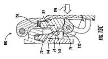
ここで図11A~図11Cを参照すると、ラッチ・アッセンブリ100をアンロック位置からロック位置へ移動させるための手順が、ラッチ・アッセンブリ100、ならびに、ベース4および蓋部5の部分の側断面図によって示されている。図11Aは、アンロック位置にあるラッチ・アッセンブリ100を示しており、図11Bは、ロッキングしているラッチ・アッセンブリ100を示しており、図11Cは、ロック位置にあるラッチ・アッセンブリ100を示している。 Here, referring to FIGS. 11A to 11C, the procedure for moving the
図11Aに示されているように、および、矢印196によって示されているように、1つの実施形態では、ユーザーは、ラッチ本体部102を押圧することによって、ラッチング・アッセンブリ100をロック位置に戻すことが可能である。図11Bに示されているように、ラッチ本体部102が内向きに押圧されると、ロッキング部材130は、ラッチ・キーパー70に接触することが可能であり、ラッチ・キーパー70は、ロッキング部材130が矢印198によって示されているように上向きに上昇することを引き起こすことが可能である。他の例では、ラッチ本体部102を内向きに押すことに加えて、ユーザーは、また、活性化部材170を外向きに引っ張り、ラッチ・アッセンブリ100をロック位置に移動させなければならない。そのような実施形態では、ラッチ・アッセンブリ100は、有利には、ロッキング部材130が活性化部材170によって上方位置に移動させられるときにのみ、アンロック位置からロック位置へ移動させられ得る。これは、コンテナ2を事故的にロックする可能性を低減させることが可能である。 As shown in FIG. 11A and as indicated by
図11Cに示されているように、フック部分142が、ラッチ・キーパー70の隆起部分の後ろに移動させられると、付勢部材150は、ロッキング部材130を下向き方向に押すことが可能である。図11Cに示されているように、ラッチ・アッセンブリ100は、ロック位置にあり、フック部分142の下側表面144は、ラッチ・キーパー70の上側表面72と係合されており、フック部分142の内向きに面する表面146は、ラッチ・キーパー70の内側表面74と係合されており、係合ラグ112は、ラッチ・キーパー70の下側表面76と係合されている。閉位置にあるときに、ラッチング・アッセンブリ100は、蓋部5がコンテナ2のベース4に当接するように位置決めされており、したがって、コンテナ2を閉じ、固定し、および/またはシールしている。追加的に、ラッチ・アッセンブリがアンロック位置(図11A)からロック位置(図11C)へ移動させられると、ガスケット30が、コンテナ2の蓋部5とベース4との間で圧縮される。したがって、ラッチ・アッセンブリ100がロック位置にあるときには、ガスケット30は、ラッチ・アッセンブリ100がアンロック位置にあるときよりも多く圧縮されている。 As shown in FIG. 11C, when the
図12A~図12Cは、ラッチ・アッセンブリ100の実施形態をロック位置からアンロック位置へ移動させることに関して、図10A~図10Cに示されているものと同様の手順を示しており、図13A~図13Cは、ラッチ・アッセンブリ100の実施形態をロック位置からアンロック位置へ移動させることに関して、図11A~図11Cに示されているものと同様の手順を示している。いくつかの実施形態では、たとえば図10A~図11Cに示されているように、活性化部材170は、それがユーザーによって外向きに回転させられた後に、図10Aに示されているような下方位置に自動的に戻ることが可能である。しかし、他の実施形態では、活性化部材170は、ユーザーによって内向きに手動で押された場合にのみ、下方位置へ移動することが可能である。追加的に、いくつかの実施形態では、活性化部材は、活性化部材が下方位置にあるときのラッチ本体部102よりもさらに外向きに延在することが可能である。 12A-12C show a procedure similar to that shown in FIGS. 10A-10C with respect to moving the embodiment of the
ラッチ・アッセンブリ100(ラッチ本体部102、ロッキング部材130、および活性化部材170を含む)は、それぞれ別々に形成され得り、また、プラスチック材料などのような材料、または、所望の形状へと形成もしくは成形され得る別の適切な材料から形成され得る。ラッチ・アッセンブリ100は、ラッチが長期間にわたってラッチ・キーパー70と係合/解除されるときに、繰り返される応力のサイクルに耐えるのに十分な構築体のサイズ、厚さ、および材料から作製され得る。本明細書で説明されているコンテナは、耐久性および耐摩耗性を提供しながら、コンテナの容易なおよび効率的な製造を保証するさまざまな特徴を含む。 The latch assembly 100 (including the
図14~図16Bは、ラッチ・アッセンブリ100を有する別の例示的なコンテナ202を示しており、同様の参照番号は、コンテナ2の中の同じまたは同様のエレメントを表しているが、200番台の参照番号を含む。コンテナ202は、コンテナ2と実質的に同様であり、したがって、コンテナ202の同様の態様は、本明細書では再び議論されてはいない。しかし、コンテナ202は、コンテナ2からのいくつかの相違点を含むことが可能である。たとえば、コンテナ202は、ハンドル240を含み、ハンドル240は、ベース4の側壁部構造体の中にベース部分204と一体的に成形され得る。図14~図16Bに示されているように、一体的に成形されたハンドル240は、J字形状の壁部259から形成され得り、および/または、J字形状の壁部259の一部分を含むことが可能である。したがって、一体的に成形されたハンドル240は、コンテナ202の周囲部の周りに延在するチャネル260の一部分を含むことが可能である。 14-16B show another
図17A~図26Dは、下記に議論されているラッチ・アッセンブリ400を有する別の例示的なコンテナ302を示しており、同様の参照番号は、コンテナ2および202の中の同じまたは同様のエレメントを表しているが、300番台の参照番号を含む。コンテナ302は、コンテナ2および202と実質的に同様であり、したがって、コンテナ302の同様の態様は、本明細書では再び議論されてはいない。しかし、コンテナ302は、コンテナ2および202からのいくつかの相違点を含むことが可能である。たとえば、コンテナ302は、ハンドル340を含み、ハンドル340は、ベース304の側壁部構造体306のそれぞれの側部308、310、312、314の上のベース部分304と一体的に成形され得る。加えて、コンテナ302は、コンテナ302に接続し得るさまざまなアクセサリーを位置付けおよび支持するための複数の取り付けポイントを含むことが可能である。これらの取り付けポイントは、より詳細に下記に説明されることとなる。 17A-26D show another
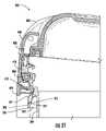
図19Aおよび図19Bとともに、図17Bに示されているように、ベース304は、ラッチ・キーパー370を含むことが可能である。ラッチ・キーパー370は、側壁部構造体306から延在することが可能であり、ベース304の中にポケットを形成することが可能である。ラッチ・キーパー370は、より詳細に下記に議論されることとなるように、ロッキング部材430の一部分を受け入れるように構成された形状を有することが可能である。ラッチ・キーパー370は、上側表面372、内側表面374、リブ375、および下側表面376を有することが可能である。リブ375は、側壁部構造体306からラッチ・キーパー370の下側表面376へ延在することが可能である。随意的に、リブ375は、また、ラッチ・キーパー370の上側表面372および下側表面376または内側表面374に接続することが可能である。リブ375は、ラッチ・キーパー370に沿って実質的に中央に位置付けされ得る。リブ375は、構造的支持をラッチ・キーパー370に追加し、耐久性を改善することが可能である。別のオプションとして、ラッチ・キーパー370は、複数のリブ375を含むことが可能であり、複数のリブ375は、ラッチ・キーパー370によって形成されたポケットのいずれかの側部に位置決めされ、追加的な支持をラッチ・キーパー370に提供することが可能である。より詳細に下記に議論されることとなるように、ラッチ・アッセンブリ400は、ラッチ・キーパー370に係合し、コンテナ302が閉構成になっているときに、蓋部305をベース304にロックすることが可能である。 As shown in FIG. 17B, along with FIGS. 19A and 19B, the base 304 can include a
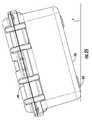
加えて、ベース304は、ラッチ・キーパー370のいずれかの側部に位置決めされている複数のランプ付きのまたはテーパー付きの表面371を含むことが可能である。ランプ付きの表面371は、ベース304のインターフェース表面336から下向きに角度が付いていることが可能であり、ここで、インターフェース表面336は、実質的に平坦になっていることが可能であり、また、ベース304の周囲部の少なくとも3つの側部の周りに延在することが可能である。ベース304のインターフェース表面336は、コンテナ302が閉位置にあるときには、蓋部305のインターフェース表面335に接触することが可能である。ランプ付きの表面371は、おおよそ45度、または、30度から60度の範囲内で、または、20度から80度の範囲内で、インターフェース表面336から下向きに角度が付いていることが可能である。ランプ付きの表面371は、コンテナ302を閉じるときに、ラッチ・アッセンブリ400がベース304の上に嵌まり込んで動きが取れなくなることを防止することが可能であり、また、蓋部305が閉じられるときに、ラッチ・アッセンブリ400の下側部分に接触し、蓋部305が図21に示されているように閉じられるときに、ベースの通り道の外へラッチ・アッセンブリ400を押し出すことが可能である。 In addition, the base 304 can include a plurality of ramped or tapered
ベース304は、複数の係合部材337をさらに含み、複数の係合部材337は、ベース304のインターフェース表面336から延在している。係合部材337は、リッジ部334の外向きに位置決めされ得る。係合部材337は、蓋部305の上の凹部またはキャビティー339の中へ延在することが可能である。係合部材337と凹部339との間の相互作用は、コンテナ302が閉位置にあるときに、および、複数のコンテナが積み重ねられているか、または、追加的なアイテムがコンテナ302の上に設置されているときに、追加的な構造的支持を提供し、蓋部305とベース304との間のジョイントを強くすることが可能である。ベース304は、任意の数の係合部材337を有することが可能である。たとえば、例示的な実施形態は、4つの係合部材337を図示しているが、ベース304は、2つの係合部材、3つの係合部材、5つの係合部材、またはそれ以上の係合部材を含むことも可能である。蓋部305の上の凹部339の数は、係合部材337の数に等しくなっていることが可能であり、ベース304のそれぞれの係合部材337に対応する場所において、蓋部305の上に位置付けされ得る。係合部材337は、例示的な実施形態では、実質的に正方形の断面形状を有しているが、円形、三角形、または他の多角形のような、任意の断面形状を有することが可能である。それぞれの係合部材337は、係合部材337の幅よりも小さいかまたはそれに等しい高さを有することが可能である。追加的に、例示的な実施形態の係合部材337および凹部339は、コンテナ302の第1の側部308の上に位置付けされているが、係合部材337および凹部339は、任意の側部の上にあることが可能であり、また、それらが複数の側部の上に位置決めされている実施形態を有することが可能である。 The base 304 further includes a plurality of engaging
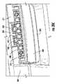
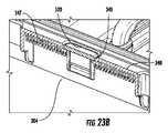
別の特徴として、ベース304は、複数のタブ321を有することが可能であり、複数のタブ321は、ベース304の側壁部構造体306の内部表面306Aに沿って位置決めされている。たとえば、図17Bおよび図19Aに示されているように、タブ321Aは、側壁部構造体306の角部のそれぞれの中に位置決めされ得る。加えて、タブ321Bおよび321Cは、第1の側部308および第2の側部310の内部表面に沿って位置決めされ得る。タブ321Bおよび321Cは、図19Aに図示されているように、互いに反対側に位置付けされ得り、それらが第1の側部308の長さに沿って整合されるようになっている。図19Aの例示的な実施形態に示されているように、内部部分は、8つのタブ321を含むことが可能であり、タブ321Aは、角部のそれぞれの中に位置付けされており、タブ321Bおよび321Cは、側壁部308、310の内部表面に沿って位置付けされている。タブ321Bおよび321Cは、概して中央に位置付けされ得り、少なくとも1つのタブ321B、321Cが、コンテナ302の中心線の近くに設置されるようになっているが、好ましくは、中心線のいずれかの側部に位置付けされるようになっている。別のオプションとして、複数のタブ321は、反対側の内部表面の上のタブ321と整合されているのではなく、互い違いの配置を有することが可能である。タブ321は、さらに下記に議論されているように、さまざまなアクセサリーのための取り付け場所を提供することが可能である。 As another feature, the base 304 can have a plurality of
それぞれのタブ321は、側壁部構造体306の内部表面306Aから延在することが可能であり、また、上側サポート表面323と、上側サポート表面323を通って延在している開口部324と、タブ321のいずれかの端部の上に1対の側部表面とを含む。それぞれのタブの上側サポート表面323は、さらに下記に議論されているようなトレイ500など、コンテナ302の内部の中にさまざまなアクセサリーを支持するための係合表面を提供することが可能である。複数のタブ321の上側サポート表面323は、互いに実質的に同一平面上にあり、サポート表面323がアクセサリーを保持することを可能にすることができ、アクセサリーは、ベース304を横切って延在し、複数のタブ321によって支持され得る。タブ321の上側サポート表面323は、ベース部分の内部部分の高さの50パーセントを超える高さにおいて、内部表面306Aの上側領域の中に位置決めされ得る。別のオプションとして、タブ321の上側サポート表面323は、ベース部分の内部部分の高さの60パーセントを超える高さに位置決めされ得り、または、さらには、ベース部分の内部部分の高さの70パーセントを超える高さに位置決めされ得る。内部スペースへの影響を最小化するために、それぞれのタブ321は、ロー・プロファイルを有することが可能であり、それぞれのタブ321が、内部表面から1インチ未満の距離、または、0.5インチ未満の距離、または、さらには、0.25インチ未満の距離に延在することができるようになっている。追加的に、開口部324は、任意の形状を有することが可能であるが、好ましくは、形状が細長くなっていることが可能である。開口部324は、ストラップまたは他の取り付け手段のための取り付けポイントを提供し、異なるアクセサリーをさらに支持することが可能である。 Each
別のオプションとして、1対のトラック326が、側壁部構造体306の内部表面306Aのうちの少なくとも2つに沿って位置決めされ得る。例示的な実施形態に示されているように、1対のトラックは、第1および第2の側部308、310の内部表面のそれぞれの上に位置決めされ得る。1対のトラック326のそれぞれは、中央に位置付けされ得り、それらが、対向する内部表面の上の1対のトラック326と整合されるようになっている。トラック326のそれぞれは、ベース304の内部表面から延在することが可能であり、内部部分の高さの大部分に沿って延在する高さを有することが可能である。内部スペースへの影響を最小化するために、それぞれのトラック326は、ロー・プロファイルを有することが可能であり、それぞれのトラック326が、内部表面306Aから1インチ未満の距離、または、0.5インチ未満の距離、または、さらには、0.25インチ未満の距離に延在することができるようになっている。トラック326の対は、除去可能な仕切り壁510(それは、まな板としての役割を果たすことも可能である)を支持し、コンテナの内部を2つの部分へと分離し、貯蔵されているアイテムをより良好に組織することが可能である。トラック326のそれぞれは、複数のディテントまたは突出部を有しており、仕切り壁510をしっかりと保持し、仕切り壁510が移動することを防止し、任意の振動を制限することが可能である。 As another option, a pair of
上記に議論されている例示的なコンテナ302と同様に、図17~図26Dの実施形態は、一体的に成形されたハンドル340を有することが可能であり、一体的に成形されたハンドル340は、側壁部308、310、312、314のそれぞれに沿って位置決めされている。一体的に成形されたハンドル340のそれぞれは、J字形状の壁部359から形成され得り、および/または、J字形状の壁部359の一部分を含むことが可能である。したがって、一体的に成形されたハンドル340は、コンテナ302の周囲部の周りに延在するチャネル360の一部分を含むことが可能である。したがって、例示的なコンテナ302は、4つのハンドル340を含むことが可能である。ハンドル340は、ベース部分304と一体的に成形され得る。いくつかの例では、それぞれのハンドル340は、アンダーカットによって形成され得り、側壁部構造体306の実質的にすべてまたは大部分に沿って延在する凹部を含むことが可能である。この一体的に成形されたハンドル340は、ベース304のための製造プロセスを簡単化することが可能である。いくつかの例では、一体的に成形されたハンドルは、破損のリスクを低減させるために、ベース304の外部表面と同一平面になっていることが可能である。 Similar to the
図22Aから図22Cに示されているように、それぞれのハンドル340は、湾曲した内部プロファイル345を有しており、ユーザーにとって人間工学的で快適なグリッピング表面を提供することが可能である。ハンドルの内部プロファイル345は、複数のハンドル・リブ347を含むことが可能であり、複数のハンドル・リブ347は、側壁部からハンドル340の内部表面へ延在しており、ここで、それぞれのハンドル・リブ347は、湾曲したプロファイルを有することが可能であり、互いに間隔を離して配置されている複数のリブ347が、ハンドル340の湾曲した内部プロファイル345を形成するようになっている。それぞれのリブ347は、リブ347同士の間に間隔を有することが可能であり、その間隔は、それぞれのリブ347の幅よりも小さくなっている。代替的に、それぞれのリブ347は、リブ347同士の間に間隔を有することが可能であり、その間隔は、それぞれの347の幅に等しいかまたはそれよりも大きくなっている。 As shown in FIGS. 22A-22C, each handle 340 has a curved
それぞれのハンドル340は、ハンドル340のハンドル上部表面343を通って延在する開口部341を有することが可能であり、ここで、それぞれの開口部341は、蓋部305の開口部349と整合することが可能である。したがって、ハンドルの開口部341と蓋部305の開口部349とが整合された状態は、ストラップまたは同様のデバイスが開口部341、349を通過するための場所が、コンテナ302をアンカー固定するかまたは縛り付けることを可能にする。それぞれの開口部341、349は、細長い形状を有することが可能であり、すべて実質的に同じ長さおよび幅を有することが可能である。したがって、これらの開口部341、349は、単にコンテナ302をアンカー固定することを超えた他の動作に関して、ユーザーに汎用性を提供することが可能である。コンテナ302をアンカー固定または固定することをさらに補助するために、蓋部305は、凹部またはチャネル351を有することが可能であり、凹部またはチャネル351は、開口部349と整合し、コンテナ302を縛り付けるストラップのためのガイド表面を提供している。別のオプションとして、クリップ520が、開口部341を通して挿入され、フックおよびループタイプ接続を使用するための追加的な場所を提供し、図23Aおよび図23Bに示されているように、追加的なアクセサリーを保持するために、オプションのさらなる汎用性を追加することが可能である。 Each handle 340 can have an
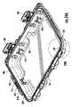
コンテナ302の蓋部305は、複数のクリップ315をさらに含むことが可能であり、複数のクリップ315は、蓋部305の内部表面309に沿って位置決めされている。たとえば、図24Aに示されているように、クリップ315Aは、内部表面325のそれぞれの上に中央に位置付けされ得り、一方、1対のクリップ315Bおよび315Cは、内部表面327、329のそれぞれに沿って均一に間隔を置いて配置され得る。また、クリップ315のそれぞれは、蓋部305の下側内部表面331の上に延在しているか、または、それに接触していることが可能である。クリップ315Bおよび315Cは、互いに反対側に位置付けされるように整合され得る。図17Bおよび図24Aの例示的な実施形態に示されているように、蓋部305は、6つのクリップ315を含むことが可能であるが、蓋部305は、任意の数のクリップ315を含むことが可能である。別のオプションとして、複数のクリップ315は、側壁部の内部表面の上に互いに反対側に位置付けされていなくてもよく、互い違いの配置を有することが可能である。クリップ315は、カーゴ・ネットもしくはバンジー・コード・ネット515、または、ユーザーによって望まれる任意のさらなるアイテムを固定するための追加的なヒッチ・ポイントを含むストラップ516などのような、さまざまなアクセサリーのための取り付け場所を提供することが可能である。 The
それぞれのクリップ315は、蓋部305の内部表面から延在することが可能であり、また、係合部材317と、係合部材317を通って延在する開口部319とを含むことが可能である。開口部319は、形状が細長くなっていることが可能であり、または、代替的に、任意の形状を有することが可能である。加えて、クリップ315の開口部319は、タブ321の開口部324と同様の幅を有することが可能である。これらの開口部319は、ストラップまたは他の取り付け手段のための取り付けポイントを提供し、図26B~図26Dに示されているように、異なるアクセサリーをさらに支持することが可能である。 Each
蓋部5に関して上記に議論されているように、蓋部305は、凹部332を含むことが可能であり、凹部332は、ガスケット330を着座させることが可能であり、凹部332は、蓋部305の周囲部の周りに延在している。凹部332は、蓋部305のインターフェース表面335の中に位置決めされ得る。凹部332は、複数のリテイニング部材333を含むことが可能であり、複数のリテイニング部材333は、図24Bに示されているように、凹部332の側部から延在している。リテイニング部材333は、凹部332の周囲部の周りの複数の場所において、ガスケット330に係合しており、凹部332の中にガスケット330を固定することが可能である。それぞれのリテイニング部材333は、少なくとも1つのテーパー付きの表面を含むことが可能であり、リテイニング部材333が、リテイニング部材の上部の近くにおいて、リテイニング部材333の中央部分の厚さよりも凹部332の開放端部に近い厚さを有するようになっている。追加的に、いくつかの例示的な実施形態では、コンテナ302は、ベース304の周囲部の周りに延在する蓋部305の凹部332の反対側に、ベース304の中にリッジ部334を含むことが可能である。リッジ部334は、ベース304のインターフェース表面336の上に位置決めされ得る。ガスケット330は、蓋部305がベース304に係合しているときに、凹部332とリッジ部334との間に設置され得る。 As discussed above with respect to the
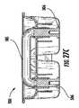
いくつかの実施形態では、底部部分320は、また、および/または、代替的に、1つまたは複数の足部322を含むことが可能であり、1つまたは複数の足部322は、テーブル、地面、または車両ベッドなどのような、表面1の上にコンテナ302を支持することが可能である。足部322は、ゴムまたはエラストマーのような滑り止め材料とは別々に形成され得り、形成された後に、ベース304に取り付けられ得る。足部322は、「ロー・プロファイル」と考慮される高さを有することが可能であり、「ロー・プロファイル」は、コンテナ302が、図25に示されているように、コンテナ302を支持する表面1に対して15度よりも大きい角度で傾けられているときに、コンテナ304がその縁部のうちの1つに沿ってスライドさせられることを可能にする。代替的に、足部322は、ベース304と一体的に形成され得る。 In some embodiments, the
図20Aから図21は、例示的なラッチ・アッセンブリ400を示しており、同様の参照番号は、ラッチ・アッセンブリ100の中の同じまたは同様のエレメントを表しているが、400番台の参照番号を含む。ラッチ・アッセンブリ400は、ラッチ・アッセンブリ100と実質的に同様であり、したがって、ラッチ・アッセンブリ100の同様の態様は、明細書では再び議論されてはいない。ラッチ・アッセンブリ400は、図20Aに示されているように、ラッチ本体部402、ロッキング部材430、付勢部材450、および活性化部材470を含む、複数のコンポーネントを含むことが可能である。上記に議論されているラッチ・アッセンブリ100と同様に、ラッチ・アッセンブリ400は、ロック位置およびアンロック位置を含むことが可能である。 20A-21 show an
ロッキング部材430は、ベース部分440および複数のフック部分442を含むことが可能であり、複数のフック部分442は、ベース部分440から内向きに延在している。複数のフック部分442は、互いからギャップ441だけ間隔を離して配置され得る。それぞれのフック部分442は、下側表面444および内向きに面する表面446をそれぞれ含むことが可能である。図20Bに示されているように、ラッチ・アッセンブリ400がロック位置にあるときに、それぞれのフック部分442の下側表面444は、ラッチ・キーパー370の上側表面372に係合することが可能であり、それぞれのフック部分442の内向きに面する表面446は、ラッチ・キーパー370の内側表面374に係合することが可能である。さらに、ラッチ・キーパー370のリブ375は、図20Cに示されているように、フック部分442のそれぞれの間のギャップ441の中にフィットされ得る。追加的に、ラッチ・アッセンブリ400がロック位置にあるときには、係合ラグ412の上側表面は、ラッチ・キーパー370の下側表面376に係合することが可能である。 The locking
ラッチ本体部402は、内側表面408の上側部分からロッキング部材430に向けて内側表面408に沿って複数のリブ413を含むことが可能である。リブ413は、輪郭を持った高さをそれぞれ有することが可能であり、それぞれのリブ413は、リブがロッキング部材430に向けて延在するにつれて、下側領域においてよりも上側領域において、より低い高さを有するようになっている。リブ413は、ラッチ・アッセンブリ400の全体的な重量を低減させながら、ラッチ本体部402を強くすることを助ける。 The
ラッチ・アッセンブリ100と同様に、ラッチ本体部402は、また、活性化部材470と枢動可能に係合され得る。また、活性化部材470は、ロッキング部材430と係合され得り、ロッキング部材430を下方位置から上方位置へ移動させるように構成され得る。活性化部材470は、ヒンジ472によって、ラッチ本体部402に枢動可能に係合され得り、ヒンジ472は、ラッチ本体部402および活性化部材470を通って延在している。活性化部材470は、グリップ部分474と、活性化バレル476と、グリップ部分474および活性化バレル476を接続する1つまたは複数のアーム478とを含むことが可能であり、ここで、活性化バレル476は、隆起部分482を含むことが可能である。隆起部分482および活性化バレル476は、実質的に平坦な接触表面483に沿って一緒に接合され得る。活性化バレル476を十分に支持するために、その領域の中のラッチ本体部402の内部表面408は、接触表面483に実質的に平行であり、接触表面483を支持することが可能であり、したがって、活性化バレル476を支持することを補助し、活性化部材470がラッチ本体部402の外側表面410を越えて後向きに回転しないように維持する。別のオプションとして、グリップ部分474は、リッジ部475を含むことが可能であり、リッジ部475は、グリップ部分474の長さの少なくとも一部分に延在し、スリップすることなしにグリップ部分474をグリップする際にユーザーをさらに補助する。 Similar to the
上記に議論されているように、ランプ付きの表面371は、ラッチ・アッセンブリがベース304の上に嵌まり込んで動きが取れなくなることがないように保護するように作用するとともに、ラッチ・キーパー370に適正に係合するようにラッチ・アッセンブリを位置決めすることを助けるように作用する。 As discussed above, the
図26A~図26Dは、上記に説明されているようなコンテナ302を図示しており、それは、さまざまなアクセサリーとともに構成されている。たとえば、図26Aは、貯蔵システムの実施形態を図示しており、貯蔵システムは、据え付けられたコンテナ302およびトレイ500を含み、ここで、トレイ500は、複数のタブ321によって支持されており、また、貯蔵システムは、1対のトラック326の間に据え付けられた仕切り壁510を含む。図26Bは、カーゴ・ネット515が蓋部305のクリップ315に取り付けられた状態の、図26Aに示されているシステムを図示している。貯蔵システムのさらに別の実施形態が、図26Cに図示されており、そこでは、コンテナ302は、1対のユーティリティー・ストラップ516とともに、タブ321によって支持されている2つのトレイ500を含み、1対のユーティリティー・ストラップ516は、蓋部305のクリップ315に接続されており、ユーザーが任意の所望のアイテムをコンテナ302の中に取り付けて整頓するための複数の場所を提供する。図26Dは、別のオプションを図示しており、そこでは、柔らかい側面の貯蔵バッグ518が、複数のジッパー付きの貯蔵コンパートメントを含む。上記に議論されているように、複数の取り付けポイントをベースおよび蓋部の中に提供することによって、コンテナ302は、貯蔵システムを提供するために、アクセサリーのさまざまなオプションを装備し、整頓された貯蔵解決策をユーザーに提供することが可能である。 26A-26D illustrate
図27A~図27Cは、トレイ500のさらなる詳細を図示している。トレイ500は、複数の貯蔵キャビティー504とともに装着表面503を備えた本体部502を有することが可能である。貯蔵キャビティー504は、任意のサイズを有することが可能であり、任意の数のキャビティー504を有するように構成され得る。たとえば、図27A~図27Cに示されている例示的な実施形態は、3つのキャビティーを含み、ここで、キャビティーのうちの2つは、第3のキャビティーよりも小さくなっている。トレイ500の別の特徴として、トレイ500は、移動可能なハンドル505を含むことが可能である。ハンドル505は、図27Bに示されている拡張位置から、図27Cに示されている収縮位置または貯蔵位置へ、垂直方向に移動することが可能である。拡張位置では、ユーザーは、コンテナ302から外へトレイ500を容易に持ち上げることが可能であり、一方、収縮位置では、トレイ500は、より低い高さプロファイルまたは貯蔵を有している。ハンドル505は、2つの端部506を備えたU字形状のチューブ状構造体を有することが可能であり、2つの端部506は、トレイの本体部502の中の開口部507の中へ係合している。チューブ状構造体のそれぞれの端部506は、開口部507の中への据え付けを可能にするテーパー付きの表面508を有することが可能であり、また、リテイニング表面509を有することが可能であり、ハンドルが除去されないように維持し、ハンドル505の垂直方向の移動を限定するポジティブ・ストップを提供する。 27A-27C illustrate further details of the
1つの態様によれば、コンテナが開示されている。コンテナは、成形されたベースを含むことが可能であり、成形されたベースは、側壁部構造体であって、側壁部構造体は、第1の側部と、第1の側部の反対側の第2の側部と、第1の側部の縁部と第2の側部の縁部との間に延在する第3の側部と、第3の側部の反対側の第4の側部とを有しており、側壁部構造体は、第1の端部および第2の端部を有している、側壁部構造体と;側壁部構造体の第1の端部に接続されている底部部分であって、底部部分は、表面の上にコンテナを支持するように構成されている、底部部分と;第1の端部の反対側に、側壁部構造体の第2の端部に形成された開口部であって、開口部は、側壁部構造体および底部部分によって形成されたコンテナの内部空洞へのアクセスを可能にするように構成されている、開口部とを含む。また、コンテナは、側壁部構造体から延在するラッチ・キーパーであって、ラッチ・キーパーは、上側表面、内側表面、および下側表面を有している、ラッチ・キーパーと;蓋部であって、蓋部は、開構成と閉構成との間で枢動可能であり、蓋部は、ベースの形状に対応する形状を有しており、コンテナが閉構成にあるときに、側壁部構造体の第2の端部に形成された開口部をカバーするように構成されている、蓋部と;蓋部をベースに接続するように構成されているヒンジであって、ヒンジの周りで、蓋部は、閉構成から開構成へ回転可能である、ヒンジとを含むことが可能である。また、コンテナは、ラッチ・アッセンブリを含むことが可能であり、ラッチ・アッセンブリは、ロック位置およびアンロック位置を有しており、ラッチ・アッセンブリは、蓋部と枢動可能に係合されているラッチ本体部であって、ラッチ本体部は、少なくとも1つの係合ラグを有している、ラッチ本体部と;ラッチ本体部とスライド可能に係合されているロッキング部材であって、ロッキング部材は、少なくとも下方位置と上方位置との間でスライド可能であり、ロッキング部材は、ロッキング部材が下方位置にあるときには、蓋部を閉構成にロックするように構成されており、ロッキング部材が上方位置にあるときには、蓋部をアンロックするように構成されている、ロッキング部材と;ラッチ本体部およびロッキング部材と係合されている付勢部材であって、付勢部材は、ロッキング部材を下方位置に付勢する、付勢部材と;活性化部材であって、活性化部材は、ラッチ本体部と枢動可能に係合されており、また、ロッキング部材と係合されており、活性化部材は、下方位置から上方位置へロッキング部材を移動させるように構成されている、活性化部材とを含む。ラッチ・アッセンブリは、ロッキング部材が上方位置にあるときにのみ、アンロック位置からロック位置へ移動させられ得る。ラッチ本体部の少なくとも1つの係合ラグは、ラッチ・アッセンブリがロック位置にあるときに、ラッチ・キーパーの下側表面に係合することが可能である。ロッキング部材の下側表面は、ラッチ・アッセンブリがロック位置にあるときに、ラッチ・キーパーの上側表面に係合している。 According to one aspect, the container is disclosed. The container can include a molded base, the molded base being a side wall structure, the side wall structure being the first side and the opposite side of the first side. The second side of the, the third side extending between the edge of the first side and the edge of the second side, and the fourth on the opposite side of the third side. The side wall structure has a first end and a second end, with the side wall structure; at the first end of the side wall structure. A connected bottom portion, the bottom portion of which is configured to support the container over the surface; with the bottom portion; on the opposite side of the first end, a second of the sidewall structures. An opening formed at the end of the container, wherein the opening is configured to allow access to the internal cavity of the container formed by the sidewall structure and the bottom portion. include. Also, the container is a latch keeper extending from the sidewall structure, the latch keeper having an upper surface, an inner surface, and a lower surface, with a latch keeper; a lid. The lid is pivotable between the open and closed configurations, the lid has a shape corresponding to the shape of the base, and the side wall structure when the container is in the closed configuration. A lid configured to cover an opening formed at the second end of the body; a hinge configured to connect the lid to the base, around the hinge. The lid can include a hinge that is rotatable from a closed configuration to an open configuration. The container can also include a latch assembly, the latch assembly has a locking and unlocking position, and the latch assembly is pivotally engaged with the lid. The latch body is a locking member that is slidably engaged with the latch body; the latch body has at least one engaging lug; the locking member is , At least slidable between the lower and upper positions, the locking member is configured to lock the lid to the closed configuration when the locking member is in the lower position, with the locking member in the upper position. At one time, a locking member configured to unlock the lid; an urging member engaged with the latch body and the locking member, the urging member with the locking member in a downward position. With the urging member; the activating member, the activating member is pivotally engaged with the latch body and is also engaged with the locking member, the activating member. , Includes an activating member configured to move the locking member from a lower position to an upper position. The latch assembly can only be moved from the unlocked position to the locked position when the locking member is in the upper position. At least one engaging lug on the latch body is capable of engaging the underside surface of the latch keeper when the latch assembly is in the locked position. The lower surface of the locking member engages the upper surface of the latch keeper when the latch assembly is in the locked position.
蓋部を閉構成から開構成へ回転させることは、蓋部を閉構成から90°回転させることを含むことが可能である。コンテナは、側壁部構造体の中に断熱材を含有することが可能である。コンテナは、第2のラッチ・アッセンブリを含むことが可能である。コンテナは、ガスケットを含むことが可能であり、ガスケットは、ベースおよび蓋部のうちの少なくとも1つの中に形成された凹部の中に配置されている。コンテナは、ベースの外部表面と一体的に成形されたチャネルを含むことが可能である。チャネルは、ベースの外部周囲部全体の周りに延在することが可能である。また、コンテナは、少なくとも1つのハンドルを含むことが可能である。ハンドルは、第1のアームおよび第2のアームを含むことが可能であり、第1のアームおよび第2のアームのそれぞれは、アームの遠位端部に隆起部分を含むことが可能である。 Rotating the lid from the closed configuration to the open configuration can include rotating the lid 90 ° from the closed configuration. The container can contain insulation in the sidewall structure. The container can include a second latch assembly. The container can include a gasket, which is located in a recess formed in at least one of the base and the lid. The container can include channels that are integrally molded with the outer surface of the base. The channel can extend around the entire outer perimeter of the base. Also, the container can include at least one handle. The handle can include a first arm and a second arm, and each of the first arm and the second arm can include a raised portion at the distal end of the arm.
別の態様によれば、コンテナが開示されている。コンテナは、ベースを含むことが可能であり、ベースは、側壁部構造体であって、側壁部構造体は、少なくとも、第1の側部と、第1の側部の反対側の第2の側部とを有しており、側壁部構造体は、第1の端部および第2の端部を有している、側壁部構造体と;側壁部構造体の第1の端部に接続されている底部部分であって、底部部分は、表面の上にコンテナを支持するように構成されている、底部部分と;第1の端部の反対側に、側壁部構造体の第2の端部に形成された開口部であって、開口部は、側壁部構造体および底部部分によって形成されたコンテナの内部空洞へのアクセスを可能にするように構成されている、開口部と;側壁部構造体から延在するラッチ・キーパーであって、ラッチ・キーパーは、上側表面、内側表面、および下側表面を有している、ラッチ・キーパーとを含む。また、コンテナは、蓋部であって、蓋部は、開構成と閉構成との間で枢動可能であり、蓋部は、ベースの形状に対応する形状を有しており、コンテナが閉構成にあるときに、側壁部構造体の第2の端部に形成された開口部をカバーするように構成されている、蓋部と;蓋部をベースに接続するように構成されているヒンジであって、ヒンジの周りで、蓋部は、閉構成から開構成へ回転可能である、ヒンジと;ラッチ・アッセンブリであって、ラッチ・アッセンブリは、ロック位置およびアンロック位置を有している、ラッチ・アッセンブリとを含むことが可能である。ラッチ・アッセンブリは、蓋部と枢動可能に係合されているラッチ本体部であって、ラッチ本体部は、少なくとも1つの係合ラグを有している、ラッチ本体部と;ラッチ本体部と係合されているロッキング部材であって、ロッキング部材は、少なくとも下方位置と上方位置との間で移動可能であり、ロッキング部材は、ロッキング部材が下方位置にあるときには、蓋部を閉構成にロックするように構成されており、ロッキング部材が上方位置にあるときには、蓋部をアンロックするように構成されている、ロッキング部材と;ラッチ本体部およびロッキング部材と係合されている付勢部材であって、付勢部材は、ロッキング部材を下方位置に付勢する、付勢部材と;活性化部材であって、活性化部材は、ラッチ本体部と枢動可能に係合されており、また、ロッキング部材と係合されており、活性化部材は、下方位置から上方位置へロッキング部材を移動させるように構成されている、活性化部材とを含むことが可能である。 According to another aspect, the container is disclosed. The container can include a base, the base being a side wall structure, wherein the side wall structure is at least a first side and a second opposite side of the first side. A side wall structure having a side portion and a side wall structure having a first end and a second end; connecting to a first end portion of the side wall structure. A bottom portion that is configured to support the container over the surface; a second portion of the sidewall structure opposite the first end. An opening formed at the end, wherein the opening is configured to allow access to the internal cavity of the container formed by the sidewall structure and the bottom portion; A latch keeper extending from the structure, the latch keeper includes a latch keeper having an upper surface, an inner surface, and a lower surface. Further, the container is a lid portion, the lid portion can be pivoted between the open configuration and the closed configuration, the lid portion has a shape corresponding to the shape of the base, and the container is closed. With a lid configured to cover an opening formed at the second end of the sidewall structure when in the configuration; a hinge configured to connect the lid to the base. And around the hinge, the lid is rotatable from the closed configuration to the open configuration, with the hinge; the latch assembly, the latch assembly has a locking and unlocking position. , Latch assembly and can be included. The latch assembly is a latch body that is pivotally engaged with the lid, the latch body having at least one engaging lug, with the latch body; with the latch body. An engaged locking member, the locking member is movable at least between a lower position and an upper position, and the locking member locks the lid to a closed configuration when the locking member is in the lower position. With a locking member configured to unlock the lid when the locking member is in the upper position; with a latch body and an urging member engaged with the locking member. The urging member is an urging member that urges the locking member to a lower position; the activating member is pivotally engaged with the latch body and is also pivotally engaged. , The activating member, which is engaged with the locking member, can include an activating member which is configured to move the locking member from a lower position to an upper position.
ロッキング部材は、ラッチ本体部とスライド可能に係合され得り、ロッキング部材は、下方位置と上方位置との間でスライド可能である。ラッチ・アッセンブリは、ロッキング部材が上方位置にあるときにのみ、アンロック位置からロック位置へ移動させられ得る。ラッチ本体部の少なくとも1つの係合ラグは、ラッチ・アッセンブリがロック位置にあるときに、ラッチ・キーパーの下側表面に係合している。ロッキング部材の下側表面は、ラッチ・アッセンブリがロック位置にあるときに、ラッチ・キーパーの上側表面に係合することが可能である。また、コンテナは、は、ガスケットを含むことが可能であり、ガスケットは、ベースおよび蓋部のうちの少なくとも1つの中に形成された凹部の中に配置されている。また、コンテナは、チャネルを含むことが可能であり、チャネルは、ベースの外部表面と一体的に成形されており、チャネルは、ベースの外部表面全体の周りに延在している。また、コンテナは、少なくとも1つのハンドルを含むことが可能であり、ハンドルは、第1のアームおよび第2のアームを有しており、第1のアームおよび第2のアームのそれぞれは、アームの遠位端部に隆起部分を含む。 The locking member may be slidably engaged with the latch body and the locking member may be slidable between the lower and upper positions. The latch assembly can only be moved from the unlocked position to the locked position when the locking member is in the upper position. At least one engagement lug on the latch body engages the underside surface of the latch keeper when the latch assembly is in the locked position. The lower surface of the locking member can engage the upper surface of the latch keeper when the latch assembly is in the locked position. Also, the container can include a gasket, which is located in a recess formed in at least one of the base and the lid. Also, the container can include channels, the channels are integrally molded with the outer surface of the base, and the channels extend around the entire outer surface of the base. Also, the container can include at least one handle, the handle having a first arm and a second arm, each of the first arm and the second arm of the arm. Includes a ridge at the distal end.
別の態様によれば、構造体のためのラッチ・アッセンブリが開示されている。構造体は、開構成および閉構成を有することが可能であり、構造体は、第2の部分に対して移動可能な第1の部分と、第1の部分と係合されているラッチ・キーパーとを含む。ラッチ・アッセンブリは、ロック位置およびアンロック位置を有しており、ラッチ・アッセンブリは、第2の部分と枢動可能に係合されているラッチ本体部と;ラッチ本体部と係合されているロッキング部材であって、ロッキング部材は、少なくとも下方位置と上方位置との間で移動可能であり、ロッキング部材は、ロッキング部材が下方位置にあるときには、蓋部を閉構成にロックするように構成されており、ロッキング部材が上方位置にあるときには、蓋部をアンロックするように構成されている、ロッキング部材と;活性化部材であって、活性化部材は、ラッチ本体部と枢動可能に係合されており、また、ロッキング部材と係合されており、活性化部材は、下方位置から上方位置へロッキング部材を移動させるように構成されている、活性化部材とを含むことが可能である。 According to another aspect, a latch assembly for the structure is disclosed. The structure can have an open configuration and a closed configuration, the structure having a first portion movable relative to the second portion and a latch keeper engaged with the first portion. And include. The latch assembly has a locking and unlocking position, and the latch assembly is engaged with a latch body that is pivotally engaged with a second portion; and with a latch body. A locking member, the locking member is movable at least between a lower position and an upper position, and the locking member is configured to lock the lid to a closed configuration when the locking member is in the lower position. The locking member is configured to unlock the lid when the locking member is in the upper position; the activating member, the activating member, pivotally engages with the latch body. Combined and engaged with a locking member, the activating member can include an activating member that is configured to move the locking member from a lower position to an upper position. ..
また、ラッチ・アッセンブリは、付勢部材を含むことが可能であり、付勢部材は、ラッチ本体部およびロッキング部材と係合されており、付勢部材は、ロッキング部材を下方位置に付勢する。ロッキング部材は、ラッチ本体部とスライド可能に係合され得り、ロッキング部材は、下方位置と上方位置との間でスライド可能である。ラッチ・アッセンブリは、ロッキング部材が上方位置にあるときにのみ、アンロック位置からロック位置へ移動させられ得る。 Further, the latch assembly can include an urging member, the urging member is engaged with the latch main body portion and the locking member, and the urging member urges the locking member to a lower position. .. The locking member may be slidably engaged with the latch body and the locking member may be slidable between the lower and upper positions. The latch assembly can only be moved from the unlocked position to the locked position when the locking member is in the upper position.
ラッチ本体部は、内側表面を含むことが可能であり、ラッチ・キーパーは、上側表面、内側表面、および下側表面を含むことが可能である。ラッチ本体部の少なくとも1つの係合ラグは、ラッチ・アッセンブリがロック位置にあるときに、ラッチ・キーパーの下側表面に係合することが可能であり、ロッキング部材の下側表面は、ラッチ・アッセンブリがロック位置にあるときに、ラッチ・キーパーの上側表面に係合することが可能である。 The latch body can include an inner surface and the latch keeper can include an upper surface, an inner surface, and a lower surface. At least one engagement lug on the latch body is capable of engaging the underside surface of the latch keeper when the latch assembly is in the locked position, and the underside surface of the locking member is the latch. It is possible to engage the upper surface of the latch keeper when the assembly is in the locked position.
本開示は、さまざまな例を参照して、上記におよび添付の図面に開示されている。しかし、本開示によって果たされる目的は、本開示に関係するさまざまな特徴および概念の例を提供することであり、本発明の範囲を限定することではない。当業者は、本開示の範囲から逸脱することなく、上記に説明されている例に対して多数の変形例および修正例が作製され得るということを認識することとなる。 The present disclosure is disclosed above and in the accompanying drawings with reference to various examples. However, an object of the present disclosure is to provide examples of various features and concepts relating to the present disclosure and not to limit the scope of the invention. Those skilled in the art will recognize that numerous modifications and modifications can be made to the examples described above without departing from the scope of the present disclosure.
Claims (27)
Translated fromJapanese成形されたベースと、
ラッチ・アッセンブリと
を含み、前記成形されたベースは、
側壁部構造体であって、前記側壁部構造体は、第1の側部と、前記第1の側部の反対側の第2の側部と、前記第1の側部の縁部と前記第2の側部の縁部との間に延在する第3の側部と、前記第3の側部の反対側の第4の側部とを有しており、前記側壁部構造体は、第1の端部および第2の端部を有している、側壁部構造体と;
前記側壁部構造体の第1の端部に接続されている底部部分であって、前記底部部分は、表面の上に前記コンテナを支持するように構成されている、底部部分と;
前記第1の端部の反対側に、前記側壁部構造体の第2の端部に形成された開口部であって、前記開口部は、前記側壁部構造体および前記底部部分によって形成された前記コンテナの内部空洞へのアクセスを可能にするように構成されている、開口部と;
前記側壁部構造体から延在するラッチ・キーパーであって、前記ラッチ・キーパーは、上側表面、内側表面、および下側表面を有している、ラッチ・キーパーと;
蓋部であって、前記蓋部は、開構成と閉構成との間で枢動可能であり、前記蓋部は、前記ベースの形状に対応する形状を有しており、前記コンテナが前記閉構成にあるときに、前記側壁部構造体の前記第2の端部に形成された前記開口部をカバーするように構成されている、蓋部と;
前記蓋部を前記ベースに接続するように構成されているヒンジであって、前記ヒンジの周りで、前記蓋部は、前記閉構成から前記開構成へ回転可能である、ヒンジと
を含み、
前記ラッチ・アッセンブリは、ロック位置およびアンロック位置を有しており、前記ラッチ・アッセンブリは、
前記蓋部と枢動可能に係合されているラッチ本体部であって、前記ラッチ本体部は、少なくとも1つの係合ラグを有している、ラッチ本体部と;
前記ラッチ本体部とスライド可能に係合されているロッキング部材であって、前記ロッキング部材は、少なくとも下方位置と上方位置との間でスライド可能であり、前記ロッキング部材は、前記ロッキング部材が前記下方位置にあるときには、前記蓋部を前記閉構成にロックするように構成されており、前記ロッキング部材が前記上方位置にあるときには、前記蓋部をアンロックするように構成されている、ロッキング部材と;
前記ラッチ本体部および前記ロッキング部材と係合されている付勢部材であって、前記付勢部材は、前記ロッキング部材を下方位置に付勢する、付勢部材と;
活性化部材であって、前記活性化部材は、前記ラッチ本体部と枢動可能に係合されており、また、前記ロッキング部材と係合されており、前記活性化部材は、前記下方位置から前記上方位置へ前記ロッキング部材を移動させるように構成されている、活性化部材と
を含み、
前記ラッチ・アッセンブリは、前記ロッキング部材が前記上方位置にあるときにのみ、前記アンロック位置から前記ロック位置へ移動させられ得り、
前記ラッチ本体部の前記少なくとも1つの係合ラグは、前記ラッチ・アッセンブリが前記ロック位置にあるときに、ラッチ・キーパーの前記下側表面に係合しており、
前記ロッキング部材のフック部分は、前記ラッチ・アッセンブリが前記ロック位置にあるときに、前記ラッチ・キーパーの前記上側表面に係合している、コンテナ。It is a container, and the container is
With a molded base,
The molded base, including the latch assembly,
A side wall structure, wherein the side wall structure includes a first side portion, a second side portion opposite to the first side portion, an edge portion of the first side portion, and the above. The side wall structure has a third side portion extending between the edge portion of the second side portion and a fourth side portion opposite to the third side portion. , With a side wall structure having a first end and a second end;
A bottom portion connected to a first end of the sidewall structure, wherein the bottom portion is configured to support the container on a surface;
An opening formed at the second end of the side wall structure on the opposite side of the first end, the opening being formed by the side wall structure and the bottom portion. With an opening configured to allow access to the inner cavity of the container;
A latch keeper extending from the sidewall structure, wherein the latch keeper has an upper surface, an inner surface, and a lower surface;
A lid, the lid is pivotable between an open configuration and a closed configuration, the lid has a shape corresponding to the shape of the base, and the container is closed. With a lid that is configured to cover the opening formed at the second end of the sidewall structure when in the configuration;
A hinge configured to connect the lid to the base, comprising a hinge around the hinge, which is rotatable from the closed configuration to the open configuration.
The latch assembly has a lock position and an unlock position, and the latch assembly has a lock position and an unlock position.
A latch body that is pivotally engaged with the lid, wherein the latch body has at least one engaging lug;
A locking member that is slidably engaged with the latch body, wherein the locking member is slidable between at least a lower position and an upper position, and the locking member is such that the locking member is below the lower position. With a locking member configured to lock the lid to the closed configuration when in position and to unlock the lid when the locking member is in the upper position. ;
An urging member engaged with the latch main body and the locking member, wherein the urging member is a urging member that urges the locking member to a lower position;
The activating member, the activating member, is pivotally engaged with the latch body portion, and is also engaged with the locking member, and the activating member is from the lower position. Including an activating member configured to move the locking member to the upper position.
The latch assembly can be moved from the unlocked position to the locked position only when the locking member is in the upper position.
The at least one engaging lug on the latch body engages the lower surface of the latch keeper when the latch assembly is in the locked position.
The hook portion of the locking member is a container that engages the upper surface of the latch keeper when the latch assembly is in the locked position.
ベースと、
ラッチ・アッセンブリと
を含み、前記ベースは、
側壁部構造体であって、前記側壁部構造体は、少なくとも、第1の側部と、前記第1の側部の反対側の第2の側部とを有しており、前記側壁部構造体は、第1の端部および第2の端部を有している、側壁部構造体と;
前記側壁部構造体の第1の端部に接続されている底部部分であって、前記底部部分は、表面の上に前記コンテナを支持するように構成されている、底部部分と;
前記第1の端部の反対側に、前記側壁部構造体の第2の端部に形成された開口部であって、前記開口部は、前記側壁部構造体および前記底部部分によって形成された前記コンテナの内部空洞へのアクセスを可能にするように構成されている、開口部と;
前記側壁部構造体から延在するラッチ・キーパーであって、前記ラッチ・キーパーは、上側表面、内側表面、および下側表面を有している、ラッチ・キーパーと;
蓋部であって、前記蓋部は、開構成と閉構成との間で枢動可能であり、前記蓋部は、前記ベースの形状に対応する形状を有しており、前記コンテナが前記閉構成にあるときに、前記側壁部構造体の前記第2の端部に形成された前記開口部をカバーするように構成されている、蓋部と;
前記蓋部を前記ベースに接続するように構成されているヒンジであって、前記ヒンジの周りで、前記蓋部は、前記閉構成から前記開構成へ回転可能である、ヒンジと
を含み、
前記ラッチ・アッセンブリは、ロック位置およびアンロック位置を有しており、前記ラッチ・アッセンブリは、
前記蓋部と枢動可能に係合されているラッチ本体部であって、前記ラッチ本体部は、少なくとも1つの係合ラグを有している、ラッチ本体部と;
前記ラッチ本体部と係合されているロッキング部材であって、前記ロッキング部材は、少なくとも下方位置と上方位置との間で移動可能であり、前記ロッキング部材は、前記ロッキング部材が前記下方位置にあるときには、前記蓋部を前記閉構成にロックするように構成されており、前記ロッキング部材が前記上方位置にあるときには、前記蓋部をアンロックするように構成されている、ロッキング部材と;
前記ラッチ本体部および前記ロッキング部材と係合されている付勢部材であって、前記付勢部材は、前記ロッキング部材を下方位置に付勢する、付勢部材と;
活性化部材であって、前記活性化部材は、前記ラッチ本体部と枢動可能に係合されており、また、前記ロッキング部材と係合されており、前記活性化部材は、前記下方位置から前記上方位置へ前記ロッキング部材を移動させるように構成されている、活性化部材と
を含み、
前記ラッチ本体部の前記少なくとも1つの係合ラグは、前記ラッチ・アッセンブリが前記ロック位置にあるときに、前記ラッチ・キーパーに係合しており、
前記ロッキング部材は、前記ラッチ・アッセンブリが前記ロック位置にあるときに、前記ラッチ・キーパーに係合している、コンテナ。It is a container, and the container is
With the base
The base, including the latch assembly,
A side wall structure, wherein the side wall structure has at least a first side portion and a second side portion opposite to the first side portion, and the side wall portion structure. The body has a side wall structure having a first end and a second end;
A bottom portion connected to a first end of the sidewall structure, wherein the bottom portion is configured to support the container on a surface;
An opening formed at the second end of the side wall structure on the opposite side of the first end, the opening being formed by the side wall structure and the bottom portion. With an opening configured to allow access to the inner cavity of the container;
A latch keeper extending from the sidewall structure, wherein the latch keeper has an upper surface, an inner surface, and a lower surface;
A lid, the lid is pivotable between an open configuration and a closed configuration, the lid has a shape corresponding to the shape of the base, and the container is closed. With a lid that is configured to cover the opening formed at the second end of the sidewall structure when in the configuration;
A hinge configured to connect the lid to the base, comprising a hinge around the hinge, which is rotatable from the closed configuration to the open configuration.
The latch assembly has a lock position and an unlock position, and the latch assembly has a lock position and an unlock position.
A latch body that is pivotally engaged with the lid, wherein the latch body has at least one engaging lug;
A locking member engaged with the latch body, wherein the locking member is movable between at least a lower position and an upper position, and the locking member has the locking member in the lower position. Occasionally, with a locking member configured to lock the lid to the closed configuration and to unlock the lid when the locking member is in the upper position;
An urging member engaged with the latch main body and the locking member, wherein the urging member is a urging member that urges the locking member to a lower position;
The activating member, the activating member, is pivotally engaged with the latch body portion, and is also engaged with the locking member, and the activating member is from the lower position.Including an activating member configured to move the locking member to the upper position.
The at least one engaging lug on the latch body engages the latch keeper when the latch assembly is in the locked position.
The locking member is a container that engages the latch keeper when the latch assembly is in the locked position .
ベースと、
ラッチ・アッセンブリと
を含み、前記ベースは、
側壁部構造体であって、前記側壁部構造体は、少なくとも、第1の側部と、前記第1の側部の反対側の第2の側部とを有しており、前記側壁部構造体は、第1の端部および第2の端部を有している、側壁部構造体と;
前記側壁部構造体の第1の端部に接続されている底部部分であって、前記底部部分は、表面の上に前記コンテナを支持するように構成されている、底部部分と;
前記第1の端部の反対側に、前記側壁部構造体の第2の端部に形成された開口部であって、前記開口部は、前記側壁部構造体および前記底部部分によって形成された前記コンテナの内部空洞へのアクセスを可能にするように構成されている、開口部と;
前記側壁部構造体から延在するラッチ・キーパーであって、前記ラッチ・キーパーは、上側表面、内側表面、および下側表面を有している、ラッチ・キーパーと;
蓋部であって、前記蓋部は、開構成と閉構成との間で枢動可能であり、前記蓋部は、前記ベースの形状に対応する形状を有しており、前記コンテナが前記閉構成にあるときに、前記側壁部構造体の前記第2の端部に形成された前記開口部をカバーするように構成されている、蓋部と
を含み、
前記ラッチ・アッセンブリは、ロック位置およびアンロック位置を有しており、前記ラッチ・アッセンブリは、
前記蓋部と枢動可能に係合されているラッチ本体部と;
前記ラッチ本体部と係合されているロッキング部材であって、前記ロッキング部材は、少なくとも下方位置と上方位置との間で移動可能であり、前記ロッキング部材は、前記ロッキング部材が前記下方位置にあるときには、前記蓋部を前記閉構成にロックするように構成されており、前記ロッキング部材が前記上方位置にあるときには、前記蓋部をアンロックするように構成されている、ロッキング部材と;
活性化部材であって、前記活性化部材は、前記ラッチ本体部と枢動可能に係合されており、また、前記ロッキング部材と係合されており、前記活性化部材は、前記下方位置から前記上方位置へ前記ロッキング部材を移動させるように構成されている、活性化部材と
を含み、
前記ラッチ本体部の前記少なくとも1つの係合ラグは、前記ラッチ・アッセンブリが前記ロック位置にあるときに、前記ラッチ・キーパーの前記下側表面に係合しており、
前記ロッキング部材のフック部分の下側表面は、前記ラッチ・アッセンブリが前記ロック位置にあるときに、前記ラッチ・キーパーの前記上側表面に係合している、コンテナ。It is a container, and the container is
With the base
The base, including the latch assembly,
A side wall structure, wherein the side wall structure has at least a first side portion and a second side portion opposite to the first side portion, and the side wall portion structure. The body has a side wall structure having a first end and a second end;
A bottom portion connected to a first end of the sidewall structure, wherein the bottom portion is configured to support the container on a surface;
An opening formed at the second end of the side wall structure on the opposite side of the first end, the opening being formed by the side wall structure and the bottom portion. With an opening configured to allow access to the inner cavity of the container;
A latch keeper extending from the sidewall structure, wherein the latch keeper has an upper surface, an inner surface, and a lower surface;
A lid, the lid is pivotable between an open configuration and a closed configuration, the lid has a shape corresponding to the shape of the base, and the container is closed. Including a lid that is configured to cover the opening formed at the second end of the sidewall structure when in the configuration.
The latch assembly has a lock position and an unlock position, and the latch assembly has a lock position and an unlock position.
With the latch body that is pivotally engaged with the lid;
A locking member engaged with the latch body, wherein the locking member is movable between at least a lower position and an upper position, and the locking member has the locking member in the lower position. Occasionally, with a locking member configured to lock the lid to the closed configuration and to unlock the lid when the locking member is in the upper position;
The activating member, the activating member, is pivotally engaged with the latch body portion, and is also engaged with the locking member, and the activating member is from the lower position.Including an activating member configured to move the locking member to the upper position.
The at least one engaging lug on the latch body engages the lower surface of the latch keeper when the latch assembly is in the locked position.
The lower surface of the hook portion of the locking member is a container that engages the upper surface of the latch keeper when the latch assembly is in the locked position .
Applications Claiming Priority (5)
| Application Number | Priority Date | Filing Date | Title |
|---|---|---|---|
| US201762518358P | 2017-06-12 | 2017-06-12 | |
| US62/518,358 | 2017-06-12 | ||
| PCT/US2018/037100WO2018231826A1 (en) | 2017-06-12 | 2018-06-12 | Container and latching system |
| US16/006,344US11203465B2 (en) | 2017-06-12 | 2018-06-12 | Container and latching system |
| US16/006,344 | 2018-06-12 |
Publications (2)
| Publication Number | Publication Date |
|---|---|
| JP2020523258A JP2020523258A (en) | 2020-08-06 |
| JP7101199B2true JP7101199B2 (en) | 2022-07-14 |
Family
ID=64562888
Family Applications (1)
| Application Number | Title | Priority Date | Filing Date |
|---|---|---|---|
| JP2019566933AActiveJP7101199B2 (en) | 2017-06-12 | 2018-06-12 | Container and latching system |
Country Status (10)
| Country | Link |
|---|---|
| US (3) | US11203465B2 (en) |
| EP (1) | EP3638598B1 (en) |
| JP (1) | JP7101199B2 (en) |
| CN (3) | CN116729803A (en) |
| AU (2) | AU2018284207B2 (en) |
| CA (1) | CA3063924A1 (en) |
| DK (1) | DK3638598T3 (en) |
| ES (1) | ES2941490T3 (en) |
| MX (1) | MX2019014178A (en) |
| WO (1) | WO2018231826A1 (en) |
Cited By (1)
| Publication number | Priority date | Publication date | Assignee | Title |
|---|---|---|---|---|
| KR20190026220A (en)* | 2017-09-04 | 2019-03-13 | 주식회사 엘지화학 | Method for Testing Mechanical Property of Electrode |
Families Citing this family (67)
| Publication number | Priority date | Publication date | Assignee | Title |
|---|---|---|---|---|
| WO2017091761A1 (en) | 2015-11-25 | 2017-06-01 | Yeti Coolers, Llc | Insulating container having vacuum insulated panels and method |
| USD873020S1 (en) | 2017-06-12 | 2020-01-21 | Yeti Coolers, Llc | Container |
| US12108853B2 (en) | 2019-01-06 | 2024-10-08 | Yeti Coolers, Llc | Luggage system |
| USD872485S1 (en)* | 2017-06-12 | 2020-01-14 | Yeti Coolers, Llc | Container |
| CA178734S (en) | 2017-06-12 | 2019-05-31 | Yeti Coolers Llc | Container |
| US11685573B2 (en) | 2017-06-12 | 2023-06-27 | Yeti Coolers, Llc | Carry strap for container |
| USD869160S1 (en) | 2017-06-12 | 2019-12-10 | Yeti Coolers, Llc | Container |
| JP7101199B2 (en) | 2017-06-12 | 2022-07-14 | イエティ クーラーズ エルエルシー | Container and latching system |
| US11976498B2 (en) | 2017-06-12 | 2024-05-07 | Yeti Coolers, Llc | Container and latching system |
| USD932585S1 (en)* | 2018-04-25 | 2021-10-05 | Axine Water Technologies Inc. | Wastewater treatment system |
| USD904829S1 (en) | 2018-12-11 | 2020-12-15 | Yeti Coolers, Llc | Container accessories |
| USD907445S1 (en) | 2018-12-11 | 2021-01-12 | Yeti Coolers, Llc | Container accessories |
| USD965409S1 (en) | 2018-12-12 | 2022-10-04 | Yeti Coolers, Llc | Latch portion |
| US10766672B2 (en) | 2018-12-12 | 2020-09-08 | Yeti Coolers, Llc | Insulating container |
| US11970313B2 (en) | 2018-12-12 | 2024-04-30 | Yeti Coolers, Llc | Insulating container |
| DE102019200068B4 (en) | 2019-01-04 | 2021-01-28 | Dometic Sweden Ab | Mobile cool box with air vents |
| DE102019200065B4 (en) | 2019-01-04 | 2020-11-12 | Dometic Sweden Ab | Mobile cool box with handle module |
| DE102019200064B4 (en) | 2019-01-04 | 2020-11-05 | Dometic Sweden Ab | Mobile cool box with locking handle opening |
| USD927938S1 (en) | 2019-01-04 | 2021-08-17 | Dometic Sweden Ab | Cooler |
| DE102019200070B4 (en) | 2019-01-04 | 2022-06-09 | Dometic Sweden Ab | Mobile cool box with hinge module |
| DE102019200067B4 (en) | 2019-01-04 | 2020-11-05 | Dometic Sweden Ab | Mobile cool box with ice maker |
| US12225993B2 (en) | 2019-01-06 | 2025-02-18 | Yeti Coolers, Llc | Luggage system |
| DK3905917T3 (en) | 2019-01-06 | 2023-09-11 | Yeti Coolers Llc | Luggage system |
| USD935280S1 (en) | 2019-11-04 | 2021-11-09 | Dometic Sweden Ab | Cover for a cooler |
| USD953814S1 (en) | 2019-11-04 | 2022-06-07 | Dometic Sweden Ab | Cover for a cooler |
| USD1002560S1 (en) | 2019-11-25 | 2023-10-24 | Fibox Oy Ab | Protective casing for electrical device |
| US11596143B2 (en) | 2019-11-26 | 2023-03-07 | Xtaris LLC | Outdoor long-term storage enclosure |
| US11401099B2 (en)* | 2019-12-20 | 2022-08-02 | California Innovations Inc. | Soft-sided insulated container with hard-sided liner |
| USD945249S1 (en)* | 2020-02-14 | 2022-03-08 | Goat Outdoor, Inc. | Cooler latch |
| USD961926S1 (en) | 2020-06-30 | 2022-08-30 | Yeti Coolers, Llc | Luggage |
| USD963344S1 (en) | 2020-06-30 | 2022-09-13 | Yeti Coolers, Llc | Luggage |
| USD951643S1 (en) | 2020-06-30 | 2022-05-17 | Yeti Coolers, Llc | Luggage |
| USD954436S1 (en) | 2020-06-30 | 2022-06-14 | Yeti Coolers, Llc | Luggage |
| USD968930S1 (en)* | 2020-07-13 | 2022-11-08 | Dam Coolers, LLC | Cooler latch |
| DE102020209896B4 (en) | 2020-08-05 | 2023-04-20 | Dometic Sweden Ab | MOBILE COOLER BOX WITH HANDLE MODULE |
| US11257311B1 (en)* | 2020-10-28 | 2022-02-22 | Benjamin Carpenter | Locking cooler assembly |
| USD960648S1 (en) | 2020-12-16 | 2022-08-16 | Yeti Coolers, Llc | Container accessory |
| USD985937S1 (en) | 2020-12-16 | 2023-05-16 | Yeti Coolers, Llc | Container |
| USD994438S1 (en) | 2020-12-16 | 2023-08-08 | Yeti Coolers, Llc | Container |
| MX2023006934A (en)* | 2020-12-16 | 2023-06-27 | Yeti Coolers Llc | Container and latching system. |
| US20220112750A1 (en)* | 2021-05-21 | 2022-04-14 | Spencer Sutlive | Detachable and Reversible Cooler Lid Hinge Assembly |
| USD964642S1 (en)* | 2021-06-13 | 2022-09-20 | Matthew Roehm | Cigarette rolling case |
| USD1031374S1 (en) | 2021-06-28 | 2024-06-18 | Dometic Sweden Ab | Container |
| US11897658B2 (en)* | 2021-11-09 | 2024-02-13 | Creative Plastic Concepts, Llc | Weatherproof sportsman's trunk |
| US12325556B2 (en) | 2021-11-16 | 2025-06-10 | II Gregory Cavett Brown | Repositionable divider and container reinforcing coupler |
| US11738914B2 (en)* | 2021-11-18 | 2023-08-29 | Yeti Coolers, Llc | Container and latching system |
| WO2023172351A1 (en)* | 2022-03-11 | 2023-09-14 | Magpul Industries Corp. | Firearm case with locking latches |
| US20240286798A1 (en)* | 2022-03-14 | 2024-08-29 | Home Depot Product Authority, Llc | Accessory attachment assembly for container |
| DE102022107470A1 (en)* | 2022-03-30 | 2023-10-05 | Amazonen-Werke H. Dreyer SE & Co. KG | Agricultural working machine and container for an agricultural working machine |
| USD1024557S1 (en)* | 2022-06-08 | 2024-04-30 | Yeti Coolers, Llc | Container |
| USD1063376S1 (en)* | 2022-06-08 | 2025-02-25 | Yeti Coolers, Llc | Container |
| USD1036116S1 (en)* | 2022-06-08 | 2024-07-23 | Yeti Coolers, Llc | Container |
| US11912477B2 (en)* | 2022-06-08 | 2024-02-27 | Yeti Coolers, Llc | Container with handle and latching system |
| JP1729885S (en)* | 2022-06-10 | 2022-11-15 | cooler box | |
| EP4302929B1 (en)* | 2022-07-04 | 2025-04-02 | Stanley Black & Decker MEA FZE | Container with a low profile latch |
| USD1032200S1 (en)* | 2022-08-24 | 2024-06-25 | Jizhang Li | Packing box |
| USD1036619S1 (en)* | 2022-10-24 | 2024-07-23 | Hach Lange Gmbh | Housing for water analyzer |
| USD1079257S1 (en)* | 2022-10-31 | 2025-06-17 | Pelican Products, Inc. | Carrying case |
| USD1036119S1 (en)* | 2022-11-30 | 2024-07-23 | Yeti Coolers, Llc | Container |
| KR102841745B1 (en)* | 2022-12-27 | 2025-08-01 | 김형선 | A container for storing roller brushes and a method for storing roller brushes using the same |
| EP4417535A1 (en)* | 2023-02-16 | 2024-08-21 | Craemer GmbH | Small container for hazardous material |
| US20240300723A1 (en)* | 2023-03-08 | 2024-09-12 | Mazarine, Inc. | Dehumidification container |
| USD1005670S1 (en)* | 2023-08-02 | 2023-11-28 | Rong Wu | Pill organizer |
| US12064863B1 (en)* | 2023-08-09 | 2024-08-20 | Chang-yu Tsai | Tool box structure |
| USD1019516S1 (en)* | 2023-08-18 | 2024-03-26 | Jiangmen Jianshun Trading Co., Ltd. | Motorcycle storage box |
| USD1020230S1 (en)* | 2023-09-29 | 2024-04-02 | Jianren Zhu | Magnetic key holder |
| USD1067373S1 (en)* | 2024-08-12 | 2025-03-18 | Shenzhen Longchengxingqi Technology Co., Ltd. | Pond fish pond water treatment filter |
Citations (3)
| Publication number | Priority date | Publication date | Assignee | Title |
|---|---|---|---|---|
| JP2004136941A (en) | 2002-10-18 | 2004-05-13 | Tenma Kk | Lid-fitted housing box |
| US20060042897A1 (en) | 2004-09-01 | 2006-03-02 | Skb Corporation | Trigger latch assembly |
| US20150352711A1 (en) | 2012-12-27 | 2015-12-10 | Keter Plastic Ltd. | Toolbox |
Family Cites Families (1283)
| Publication number | Priority date | Publication date | Assignee | Title |
|---|---|---|---|---|
| US286909A (en) | 1883-10-16 | Miles commandee | ||
| DE74708C (en) | J. L. JONES in Chicago, V.St.A | Lock with locking lever | ||
| US749959A (en) | 1904-01-19 | Garment-holding attachment for trunks | ||
| CA60997A (en) | 1897-12-23 | 1898-08-23 | William Morton | Gold saving apparatus |
| CA72336A (en) | 1900-11-12 | 1901-07-16 | Gray, William | Tobacco stripping machine |
| CA72338A (en) | 1900-12-13 | 1901-07-16 | The John R. Williams Company | Cigar-making machine |
| CA72337A (en) | 1901-03-02 | 1901-07-16 | John Robert Williams | Tobacco stripping and booking machine |
| CA73327A (en) | 1901-08-31 | 1901-10-08 | Charles Giles Smith | Bed spring |
| CA77273A (en) | 1902-08-02 | 1902-09-02 | Daniel Daggett | Calf weaner |
| CA81456A (en) | 1903-04-14 | 1903-06-23 | Manley J. Chaplin | Tap for beer barrels |
| CA89737A (en) | 1904-04-05 | 1904-10-25 | Edward Graham | Process of manufacturing paint vehicles |
| US1008041A (en) | 1911-04-12 | 1911-11-07 | Elof R Leonard | Sash-governing appliance. |
| US1056648A (en) | 1912-02-06 | 1913-03-18 | James J Earley | Trunk attachment. |
| CA152411A (en) | 1913-09-25 | 1913-12-09 | Damase Jacques | Winch |
| CA175939A (en) | 1917-02-12 | 1917-03-27 | Frederick Fenner | Distillation of mineral oil |
| CA175930A (en) | 1917-02-28 | 1917-03-27 | William E. Chesney | Rail tie |
| US2101337A (en) | 1934-12-19 | 1937-12-07 | Excelsior Hardware Company | Lockable hasp fastener |
| US2109928A (en) | 1935-12-05 | 1938-03-01 | Passalacqua Diego | Strongbox |
| US2510643A (en) | 1946-02-01 | 1950-06-06 | Adrian L Long | Plastic suitcase sections having embedded-hinge and meeting-edge gasket |
| US2439660A (en) | 1946-06-19 | 1948-04-13 | Keil Rudolph | Wheeled trunk and the like |
| US2565939A (en) | 1947-04-10 | 1951-08-28 | Roderic T Wriston | Lined waterproof container |
| US2472491A (en) | 1947-07-01 | 1949-06-07 | Quinton Bernard | Mobile luggage |
| US2574089A (en) | 1948-06-08 | 1951-11-06 | Cochran Jacqueline | Luggage case having a removable lining |
| US2581417A (en) | 1948-07-29 | 1952-01-08 | Jones Wendell Cooley | Luggage carrier having projectable and retractible supporting rollers |
| US2577951A (en) | 1949-04-13 | 1951-12-11 | Cortsen Eiler Johan | Retractable wheel arrangement for baggage |
| US2604961A (en) | 1950-04-17 | 1952-07-29 | Maurice P Koch | Luggage sealing device |
| US2647653A (en) | 1950-09-18 | 1953-08-04 | John B Dube | Insulated container for perishable substances |
| US2717093A (en) | 1950-10-28 | 1955-09-06 | Skydyne Inc | Shipping case or the like |
| US2747732A (en) | 1952-03-13 | 1956-05-29 | Compco Corp | Shipping case and storage chest |
| US2803956A (en) | 1954-06-04 | 1957-08-27 | David R Womer | Lock and latch device |
| US2869909A (en) | 1955-05-11 | 1959-01-20 | Mc Graw Edison Co | Latch |
| US2931205A (en) | 1956-12-10 | 1960-04-05 | Whirlpool Co | Latch mechanism |
| GB854540A (en) | 1958-05-01 | 1960-11-23 | Bloxvich Lock Stamping | Catch for vehicle bonnets or other closures |
| CH365631A (en) | 1959-01-03 | 1962-11-15 | Amiet & Hofmann F Amie | Lock for suitcases, folders and the like |
| US2936189A (en) | 1959-02-27 | 1960-05-10 | Peter Begelman | Receptacle safety latch means |
| US3057636A (en) | 1960-08-16 | 1962-10-09 | Bonnie R D Ettorre | Luggage means with retractable wheels |
| US3191244A (en) | 1962-03-27 | 1965-06-29 | Nat Lock Co | Sectional cooler latch |
| US3141680A (en) | 1962-05-02 | 1964-07-21 | Goldwin C Mccord | Portable luggage having retractable wheels |
| GB1041392A (en) | 1962-08-30 | 1966-09-07 | Gen Electric | Improvements relating to electric incandescent filament lamps |
| US3202310A (en) | 1963-05-10 | 1965-08-24 | Texas Tennessee Ind Inc | Hinge and latch assembly |
| US3259412A (en) | 1963-12-17 | 1966-07-05 | Camloc Fastener Corp | Safety device for toggle latch |
| US3225983A (en) | 1964-05-06 | 1965-12-28 | Andrew J Majka | Combination fishing creel and portable cooler |
| US3250558A (en) | 1965-01-04 | 1966-05-10 | Aerpat Ag | Flush mounting latch |
| US3519298A (en)* | 1967-02-24 | 1970-07-07 | Rex Chainbelt Inc | Positive lock for toggle latch |
| US3432025A (en) | 1967-03-08 | 1969-03-11 | Carl A Luhe | Insulated individual lunch case |
| US3464579A (en) | 1967-06-01 | 1969-09-02 | Shell Oil Co | Water-tight plastic container |
| US3416701A (en) | 1967-11-22 | 1968-12-17 | Life Like Products Inc | Combined latch and handle |
| US3565305A (en) | 1969-05-27 | 1971-02-23 | Paul Belokin Jr | Car carrier means |
| US3642168A (en) | 1969-10-27 | 1972-02-15 | Rudkin Wiley Corp | Nontilt stacking and nesting container |
| JP3678925B2 (en) | 1998-11-26 | 2005-08-03 | Ykk株式会社 | Fasteners with tape |
| US3656650A (en) | 1970-06-11 | 1972-04-18 | Container Dev Corp | Compartmentalized container |
| US3661410A (en) | 1970-07-07 | 1972-05-09 | Keystone Consolidated Ind Inc | Panel latching mechanism |
| US3688942A (en) | 1970-11-20 | 1972-09-05 | Continental Can Co | Container and closure combination |
| US3741433A (en) | 1971-03-15 | 1973-06-26 | Voplex Corp | Box having a carrying handle-latch |
| US3690708A (en) | 1971-05-12 | 1972-09-12 | Coleman Co | Pressure-releasing latch assembly for picnic coolers |
| BE781886A (en) | 1972-04-10 | 1972-07-31 | Spumalit Anstalt | FLESSENKRAT. |
| US3902628A (en) | 1972-09-13 | 1975-09-02 | Plastic Forming Company Inc | Plastic container hinge and latch |
| DE2356011C3 (en) | 1972-11-13 | 1982-02-04 | Danincit ApS, Ishoej | Mobile travel case |
| US3933269A (en) | 1972-12-26 | 1976-01-20 | Family Products, Inc. | Handle assembly for chest |
| FR2223248A1 (en) | 1973-03-29 | 1974-10-25 | Allibert Exploitation | Plastic crate for stacking in piles - sides are strengthened by hollow pillars to allow stacking at right angles |
| US3831224A (en)* | 1973-04-02 | 1974-08-27 | Rexnord Inc | Toggle latch with yoke |
| US3847423A (en) | 1973-04-02 | 1974-11-12 | Rexnord Inc | Dual spring action self adjusting latch |
| US3861504A (en) | 1973-06-06 | 1975-01-21 | Marion C Mcgraw | Luggage with transparent liner |
| US3882914A (en) | 1973-07-16 | 1975-05-13 | Tote Pak Co | Carrying strap construction |
| US3915362A (en) | 1974-01-14 | 1975-10-28 | Donald G Hart | Vehicle luggage carrier and complementary mounting members |
| LU72256A1 (en) | 1974-04-11 | 1975-08-20 | ||
| US3886625A (en) | 1974-07-05 | 1975-06-03 | Ernest J Rollband | Dual handle construction for caskets |
| US3955656A (en) | 1974-08-30 | 1976-05-11 | Kashinski Albert A | Elastic cover and seal for protecting luggage |
| DE7502524U (en) | 1975-01-29 | 1975-09-18 | Theysohn Friedrich | Stackable bottle or transport box with hollow corners |
| AT335787B (en) | 1975-04-23 | 1977-03-25 | Hirsch Hans & Soehne | WATCH STRAP |
| US3987829A (en) | 1975-05-05 | 1976-10-26 | Leone Anthony J | Container with lid |
| US4095711A (en) | 1976-08-20 | 1978-06-20 | The Coleman Company, Inc. | Handle assembly |
| DK139257B (en) | 1976-10-20 | 1979-01-22 | Kevi As | Furniture roller with brake means. |
| US4116479A (en) | 1977-01-17 | 1978-09-26 | Hartwell Corporation | Adjustable flush mounted hook latch |
| US4094392A (en) | 1977-03-01 | 1978-06-13 | Samsonite Corporation | Luggage latch mechanism |
| USD257218S (en) | 1977-11-08 | 1980-10-07 | Lars Eriksson | Toggle joint fastener |
| US4153178A (en) | 1978-04-14 | 1979-05-08 | Minnesota Mining And Manufacturing Company | Double-acting latch for hinged plastic box |
| DE2825722C2 (en) | 1978-06-12 | 1984-09-06 | Windmöller & Hölscher, 4540 Lengerich | Device for the production of bags or sacks and for their deposition in imbricated formation |
| US4184705A (en)* | 1978-06-16 | 1980-01-22 | Weber-Knapp Company | Hood latch |
| GB2023551B (en) | 1978-06-19 | 1982-03-10 | Drg Ltd | Folding flaps |
| GB2023549A (en) | 1978-06-23 | 1980-01-03 | Loewy Robertson Eng Co Ltd | Web Accumulators |
| IL55179A (en) | 1978-07-20 | 1981-07-31 | Ernest Reginald Tickton | Firing deck insert for mounting a fuel injector,sparking plug or the like in internal combustion engines |
| US4245937A (en) | 1978-09-28 | 1981-01-20 | Kennametal Inc. | Clamping mechanism for cutting insert |
| GB2031853B (en) | 1978-10-02 | 1982-08-11 | Superior Sa | Hand luggage |
| US4249760A (en) | 1979-01-05 | 1981-02-10 | The Coleman Company, Inc. | Latch assembly |
| USD256630S (en) | 1979-02-08 | 1980-09-02 | Maney Thomas H | Knapsack cooler |
| GB2045135B (en) | 1979-04-06 | 1982-10-20 | Babcock & Wilcox Co | Forming dies and methods of forming tubular fittings |
| DE2916308C3 (en) | 1979-04-23 | 1982-02-25 | Deutsche Vereinigte Schuhmaschinen Gmbh, 6000 Frankfurt | Gluing press for gluing outer soles to listed shoes |
| EP0026076B1 (en) | 1979-09-20 | 1983-06-29 | WES Limited | Improvements relating to storage and transport containers |
| US4273223A (en) | 1979-09-24 | 1981-06-16 | Tomlinson Lenore E | Protective insert for use with soft-sided luggage |
| US4254850A (en) | 1979-10-29 | 1981-03-10 | Knowles Harford E | Luggage case |
| US4592482A (en) | 1980-11-14 | 1986-06-03 | King-Seeley Thermos Co. | Handle mechanism for cooler or the like |
| US4351165A (en) | 1981-01-07 | 1982-09-28 | Marten Gottsegen | Portable cooler |
| US4343412A (en) | 1981-02-19 | 1982-08-10 | Show-Pak Incorporated | Hinge for carrying case |
| JPS6012847Y2 (en) | 1981-03-16 | 1985-04-24 | コクヨ株式会社 | drawer latch device |
| NL8102993A (en) | 1981-06-22 | 1983-01-17 | Wavin Bv | PLASTIC HOLDER WITH REINFORCED CORNER COLUMN. |
| US4446705A (en) | 1982-05-12 | 1984-05-08 | Environmental Testing & Certif. Corp. | Shipping container |
| DE3242265A1 (en) | 1982-11-15 | 1984-05-17 | Dieter 5000 Köln Morszeck | CASE WITH A LEVER LOCK |
| US4561526A (en) | 1983-01-03 | 1985-12-31 | Samsonite Corporation | Steering and support handle for wheeled luggage |
| US4575109A (en) | 1983-02-28 | 1986-03-11 | Cowdery Timothy K | Luggage case with retractable wheels |
| US4465189A (en) | 1983-04-11 | 1984-08-14 | American Safety Flight Systems, Inc. | Waterproof container |
| FR2546140B1 (en) | 1983-05-20 | 1985-07-26 | Aerospatiale | PRESSURE BALANCING DEVICE WATERTIGHT FROM RAIN OR RUNOFF, ESPECIALLY FOR TRANSPORT CONTAINER |
| US4523692A (en) | 1983-06-30 | 1985-06-18 | Jack Lemkin | Reversible security cover for stackable and nestable tote box |
| US4522312A (en) | 1983-09-14 | 1985-06-11 | Southern Case, Inc. | Container and associated latch structure |
| US4515421A (en) | 1983-11-07 | 1985-05-07 | The Coleman Company, Inc. | Multiple use shelf for cooler |
| DE3344410A1 (en) | 1983-12-08 | 1985-06-20 | Henk 4459 Ringe Reinders | Plastic bottle crate |
| US4615464A (en) | 1983-12-21 | 1986-10-07 | Custom-Pak, Incorporated | Molded container case with hinge and method for making same |
| US4573202A (en) | 1984-01-20 | 1986-02-25 | Aaron Lee | Container with inflatable, floating liner of uniform thickness |
| JPS60164570A (en) | 1984-02-06 | 1985-08-27 | 株式会社東芝 | Door lock apparatus |
| US4550813A (en) | 1984-03-28 | 1985-11-05 | Browning Arthur J | Molded wheeled luggage, ensemble thereof and process for making the same |
| EP0175022A1 (en) | 1984-09-06 | 1986-03-26 | SAMSONITE CORPORATION (a Delaware corporation) | Steering handle for luggage case |
| USD290908S (en) | 1985-07-25 | 1987-07-21 | Accessories by Us, Inc. | Combined carrying bag for infant accessories and changing mat |
| JPH0354566Y2 (en) | 1985-10-22 | 1991-12-03 | ||
| ATE123632T1 (en) | 1985-10-31 | 1995-06-15 | Samsonite Corp | SUITCASE. |
| JPS62155805A (en) | 1985-12-27 | 1987-07-10 | モリト株式会社 | Snap fastener and its production |
| US4707011A (en) | 1986-01-13 | 1987-11-17 | Mckim Jr Richard L | Handle attachment for cardboard boxes |
| US4712657A (en) | 1986-02-12 | 1987-12-15 | Andiamo Inc. | Method and means for sealing a carrying case |
| US4662188A (en) | 1986-02-21 | 1987-05-05 | Hullihan Michael J | Portable cooler or ice chest |
| US4768815A (en) | 1986-04-23 | 1988-09-06 | Rexnord Inc. | Supplemental locking mechanism for a tension latch assembly |
| DE8620597U1 (en) | 1986-05-09 | 1986-09-11 | Van Niftrik B.V., Putte | Bottle crate for storing bottles while maintaining the greatest possible visibility of these bottles |
| US4673207A (en) | 1986-10-14 | 1987-06-16 | Collins & Aikman | One-piece automotive trunk liner |
| US4746008A (en) | 1987-07-01 | 1988-05-24 | Heverly Karen H | Child-resistant box for storage of hazardous materials |
| US4802344A (en) | 1987-07-06 | 1989-02-07 | Livingston Mark L | Portable cooler for beverage kegs |
| US4775072A (en) | 1987-07-29 | 1988-10-04 | The Coleman Company, Inc. | Handle assembly for insulated container |
| US4792024A (en) | 1987-10-09 | 1988-12-20 | The Quaker Oats Company | Changing caddy including a removable changing pad for an infant |
| US4826060A (en) | 1988-03-17 | 1989-05-02 | Hollingsworth W Dale | Cooler bag |
| US4917261A (en) | 1988-03-18 | 1990-04-17 | Placon Corporation | Vacuum-formed container with u-shaped lock |
| US5080250A (en) | 1988-05-19 | 1992-01-14 | Contico International, Inc. | Floor mounted pickup truck boxes |
| USD329135S (en) | 1988-05-23 | 1992-09-08 | Rubbermaid Incorporated | Tool caddy |
| JP2569734B2 (en) | 1988-06-21 | 1997-01-08 | 旭硝子株式会社 | Liquid crystal optical element, method of manufacturing the same, and liquid crystal display device using the same |
| US4899904A (en) | 1988-10-03 | 1990-02-13 | Dooley Leslie T | Beverage can cartridge |
| FR2638950A1 (en) | 1988-11-17 | 1990-05-18 | Savebag | Suitcase with an inner lining which is at least partially removable |
| US4858444A (en) | 1988-11-18 | 1989-08-22 | Jeff Scott | Portable cooler |
| FR2641953B1 (en) | 1989-01-20 | 1991-04-05 | Delsey Soc | HANGING DEVICE FOR SUITCASE STRAPS |
| US4975073A (en) | 1989-02-13 | 1990-12-04 | Calmark Corporation | Insertion and extraction aid for printed circuit card |
| DE8911266U1 (en) | 1989-03-22 | 1989-11-30 | E. Damberg Group A/S, Nykoebing Falster | Portable box |
| US4873841A (en) | 1989-04-03 | 1989-10-17 | William Bradshaw | Portable cooler |
| US4904007A (en) | 1989-04-07 | 1990-02-27 | Coleman Outdoor Products, Inc. | Releasing latch assembly for picnic coolers |
| NL8901236A (en) | 1989-05-18 | 1990-12-17 | Stamicarbon | HOLDER FITTED WITH A LOCKABLE LID. |
| US5011020A (en) | 1989-07-19 | 1991-04-30 | The Board Of Regents, The University Of Texas System | Cytotoxic agent containment kit |
| US4930649A (en) | 1989-08-18 | 1990-06-05 | North American Roto-Molding Corp. | Refuse container with molded hinge |
| NL8902264A (en) | 1989-09-11 | 1991-04-02 | Wavin Bv | BOTTLE CRATE. |
| US5062557A (en) | 1989-10-13 | 1991-11-05 | Mahvi A Pascal | Infant care bag |
| USD328186S (en) | 1989-10-23 | 1992-07-28 | Hamaphot Kg Hanke & Thomas | Shoulder carrying strap for a bag |
| JPH0366374U (en) | 1989-11-01 | 1991-06-27 | ||
| NL8903105A (en) | 1989-12-19 | 1991-07-16 | Wavin Bv | Plastic crate with hollow column - has gas-injection opening in column with sealing wall below |
| DE9000273U1 (en) | 1990-01-12 | 1991-05-08 | Sudhaus Schloß- und Beschlagtechnik GmbH + Co, 5860 Iserlohn | Closure for containers, cases, etc. consisting of wall parts that can be moved relative to one another. |
| US5087798A (en) | 1990-03-14 | 1992-02-11 | Rodgers Instrument Corporation | Illuminated elastomeric rocker switch assembly |
| GB2242016B (en) | 1990-03-15 | 1994-06-29 | Connabride Plastics | Thermally insulating carriers |
| US5011013A (en) | 1990-04-27 | 1991-04-30 | Waterloo Industries, Inc. | Portable storage container |
| USD334870S (en) | 1990-07-02 | 1993-04-20 | Christopher Griffin | Insulated cooler |
| CN2073459U (en) | 1990-07-03 | 1991-03-20 | 蔡文林 | Fire hydrant box lock |
| US5024471A (en) | 1990-07-25 | 1991-06-18 | Rubbermaid Incorporated | Safety release latch |
| US5075925A (en) | 1990-07-26 | 1991-12-31 | Rubbermaid Incorporated | Retractable handle assembly for a transportable case |
| USD335030S (en) | 1990-07-27 | 1993-04-27 | International Business Machines Corporation | Carrying case for a personal computer |
| JPH0742328Y2 (en) | 1990-08-10 | 1995-10-04 | ワイケイケイ株式会社 | Female hook with a snap button |
| CA2052086C (en) | 1990-09-12 | 1995-05-09 | Patrick T. Ryan | Vehicle luggage compartment liner |
| US5153561A (en) | 1990-09-19 | 1992-10-06 | Johnson Eric S | Secured valuable box for beach goers |
| USD327427S (en) | 1990-11-20 | 1992-06-30 | Imperial Wallcoverings, Inc. | Package for wallpaper border |
| US5040834A (en) | 1990-11-29 | 1991-08-20 | Rubbermaid Incorporated | Lockable latch for a container |
| DE4038218A1 (en) | 1990-11-30 | 1992-06-04 | Franzen Soehne S | LOCKING, ESPECIALLY FOR CASES OR THE LIKE |
| US5117952A (en) | 1990-12-28 | 1992-06-02 | Suh Young H | Portable safety bag |
| USD333775S (en) | 1991-02-20 | 1993-03-09 | Southco, Inc. | Flexible draw latch |
| DE9105033U1 (en) | 1991-04-24 | 1992-03-26 | Fliege + Schmucker GmbH, 8025 Unterhaching | Container for components and/or accessories of a mobile data processing system |
| US5139294A (en) | 1991-04-26 | 1992-08-18 | Southern Case, Inc. | Latch bearing for blow-molded case, and method and apparatus for forming same |
| FR2689100A1 (en) | 1991-06-20 | 1993-10-01 | Yoshida Industry Co | Container structure - has pivoting cover operated by flexible rod, whose reaction force maintains cover sealed on container body, and locking mechanism for closed position |
| US5096030A (en) | 1991-07-25 | 1992-03-17 | Espinosa Erlinda O | Luggage unit with pull-out article-receiving pouch |
| JPH0563066A (en) | 1991-08-30 | 1993-03-12 | Shin Etsu Handotai Co Ltd | Structure for engagement with wafer container |
| US5169018A (en) | 1991-09-20 | 1992-12-08 | Woodstream Corporation | Tackle box with lid-latching handle |
| CA2079977A1 (en) | 1991-10-10 | 1993-04-11 | Brent A. Ledet | Drive sprocket systems for registration of spaced metal laminations across the width of plastic conveyor belts |
| USD342609S (en) | 1991-12-26 | 1993-12-28 | Rubbermaid Incorporated | Storage container |
| USD340167S (en) | 1991-12-26 | 1993-10-12 | Rubbermaid Incorporated | Ice chest |
| JP3225244B2 (en) | 1992-04-13 | 2001-11-05 | 旭電化工業株式会社 | Segment seal structure |
| US5205413A (en) | 1992-05-21 | 1993-04-27 | Dart Industries Inc. | Lunchbox with reversible cover |
| GB2253781B (en) | 1992-05-26 | 1993-04-28 | Lyndon Ivor Bowen | Suitcase,removable protective cover |
| US5295369A (en) | 1992-06-15 | 1994-03-22 | Garcia Kenneth M | Water and ice cooler combination |
| CN2132145Y (en) | 1992-06-24 | 1993-05-05 | 陈则韶 | Cold storage box and heat storage box |
| US5235830A (en) | 1992-08-20 | 1993-08-17 | Benge James A | Locking device for openable containers |
| JP3177720B2 (en) | 1992-08-26 | 2001-06-18 | パイロットインキ株式会社 | Thermochromic water-repellent artificial hair for toys and method for producing the same |
| US5454477A (en) | 1992-09-04 | 1995-10-03 | Vari-Lite, Inc. | Storage and transporatation trunk for lighting equipment |
| GB9219322D0 (en) | 1992-09-11 | 1992-10-28 | Dzus Fastener Europe | Lever mechanism |
| US5282706A (en) | 1992-09-24 | 1994-02-01 | Indiana Mills & Manufacturing, Inc. | Retractable tie-down assembly |
| US5269157A (en) | 1992-10-13 | 1993-12-14 | Michael Ciminelli | Insulated beach box with utility attachments |
| US5335451A (en) | 1992-10-29 | 1994-08-09 | Aluma Shield Industries, Inc. | Insulated smoke doors for cooler/freezer applications |
| SE500577C2 (en) | 1992-11-04 | 1994-07-18 | Perstorp Ab | Plastic lid with associated plastic box |
| US5213381A (en) | 1992-11-25 | 1993-05-25 | The Hartwell Corporation | Draw latch |
| WO1994012370A1 (en) | 1992-12-01 | 1994-06-09 | Neocon International Inc. | Vehicle luggage compartment liner |
| USD347971S (en) | 1992-12-14 | 1994-06-21 | Krugman Kenneth J | Beverage can cooler tote |
| USD355568S (en) | 1993-02-10 | 1995-02-21 | Canadian Thermos Products Inc. | Cooler |
| US5322178A (en) | 1993-04-21 | 1994-06-21 | Plastofilm Industries, Inc. | One-hand operable latch for tub type container |
| US5402557A (en) | 1993-05-03 | 1995-04-04 | Dalen; Thomas M. | Dynamic self-adjusting tie-down device for transportable items |
| US5313817A (en) | 1993-05-07 | 1994-05-24 | Meinders Larry L | Wheelable, storable cooler |
| USD351533S (en) | 1993-05-19 | 1994-10-18 | Lynam Jr Clifton C | Cooler for golfers |
| WO1994027014A2 (en) | 1993-05-19 | 1994-11-24 | Dzus Fastener Europe Limited | A latch |
| GB2278874B (en) | 1993-06-11 | 1996-06-19 | Yuan Shan Ind Co Ltd | A latch assembly for a luggage case and a luggage case with such latch assembly |
| USD361888S (en) | 1993-06-28 | 1995-09-05 | Rubbermaid Specialty Products Inc. | Front access tackle box |
| US5435256A (en) | 1993-07-06 | 1995-07-25 | Svehaug; Oswald C. | Refrigerator safe box |
| US5353946A (en) | 1993-07-26 | 1994-10-11 | Church & Dwight Co., Inc. | Container with reclosable lid latch |
| US5423644A (en) | 1993-08-05 | 1995-06-13 | R.C. First Enterprises, Inc. | Cargo tie-down having mechanical advantage |
| JP3517791B2 (en) | 1993-08-11 | 2004-04-12 | 株式会社小松電業所 | Door locking device |
| FR2711044B1 (en) | 1993-10-15 | 1997-08-29 | Samsonite Corp | Baggage provided with sophisticated holding means. |
| FR2712257B1 (en) | 1993-11-10 | 1996-02-02 | Transrack Sa | Flat and folding handling handle, in particular for boxes of electrical and / or electronic equipment and box fitted with such a handle. |
| US5358082A (en) | 1993-11-10 | 1994-10-25 | Armstrong Iv James E | Expandable luggage combining hardside and softside materials |
| US5518139A (en) | 1993-11-24 | 1996-05-21 | Waterloo Industries, Inc. | Portable storage assembly |
| US5570915A (en) | 1993-11-30 | 1996-11-05 | Adams Rite Sabre International | Flush-mounted door latch |
| US5431263A (en) | 1993-11-30 | 1995-07-11 | Lenox, Incorporated | Mobile carry-on suitcase |
| US5564805A (en) | 1994-01-03 | 1996-10-15 | Contico International, Inc. | Storage container with wheels |
| USD358765S (en) | 1994-01-03 | 1995-05-30 | Contico International, Inc. | Storage container with wheels |
| USD359836S (en) | 1994-01-12 | 1995-07-04 | Shuler Curtis P | Safety belt |
| US5373708A (en) | 1994-01-25 | 1994-12-20 | Dumoulin, Jr.; Joseph C. | Cooler with fold-down corner wheels, a pop-up pull handle, integral bottle and fold down cutting board |
| US5620213A (en) | 1994-02-08 | 1997-04-15 | Ellis; Frederick G. | Window lock |
| US5465985A (en) | 1994-04-13 | 1995-11-14 | Devan; Colleen M. | Wheeled portable cooler |
| US5865281A (en) | 1994-05-23 | 1999-02-02 | Wang; King Sheng | Retractable luggage handle mounting hardware |
| US5526953A (en) | 1994-05-24 | 1996-06-18 | Chieng; Walter | Portable box for containing V8 video tapes |
| DE9408707U1 (en) | 1994-05-27 | 1995-09-28 | S. Franzen Söhne (GmbH & Co), 42719 Solingen | Closure, especially for suitcases or the like. |
| US5568848A (en) | 1994-07-01 | 1996-10-29 | Liang; Joseph | Laterally movable suitcase with wheeled, pivotable leg |
| GB2291042A (en) | 1994-07-05 | 1996-01-17 | Dick Ming Hsieh | Wheel assembly of a luggage |
| EP0771160B1 (en) | 1994-07-19 | 1998-09-30 | Justine Wonka | Suitcase with variable capacity |
| US5524737A (en) | 1994-07-29 | 1996-06-11 | Wang; King-Sheng | Retractable handle and wheel assembly for travel bags |
| US5427308A (en) | 1994-08-10 | 1995-06-27 | Eco-Cool, Inc. | Container with integral handles and locking tabs |
| USD367360S (en) | 1994-08-11 | 1996-02-27 | Rubbermaid Incorporated | Compartmented lid for toolbox |
| USD370619S (en) | 1994-08-12 | 1996-06-11 | Black & Decker Inc. | Over-center latch for a utility box |
| USD371942S (en) | 1994-08-18 | 1996-07-23 | Lippincott Shawn E | Portable cooler |
| US5419432A (en) | 1994-08-31 | 1995-05-30 | Ingram; Joyce L. | Garment bag for dresser |
| US5533231A (en) | 1994-09-12 | 1996-07-09 | Bai; Yang-Fong | Concealable caster of baggage |
| JPH0893298A (en) | 1994-09-24 | 1996-04-09 | Kyoei Kogyo Kk | Door latch device for furniture etc. |
| US5704158A (en) | 1994-09-30 | 1998-01-06 | Whiteaker; Michael E. | Tackle management system |
| US5478097A (en) | 1994-10-25 | 1995-12-26 | Forma; Warren | Golf bag with retractable wheel system |
| US5519919A (en) | 1994-12-12 | 1996-05-28 | Lee; Rui-Ming | Retractable handle assembly |
| USD368161S (en) | 1994-12-15 | 1996-03-26 | Rubbermaid Incorporated | Storage locker lid |
| USD369695S (en) | 1994-12-27 | 1996-05-14 | Imotani Industry Co., Ltd. | Ice-box with a folding table |
| US5575362A (en) | 1995-01-05 | 1996-11-19 | Samsonite Corporation | Collapsible pull handle for wheeled garment bag |
| USD364426S (en) | 1995-03-20 | 1995-11-21 | Rubbermaid Office Products Inc. | File box |
| DE19512301A1 (en) | 1995-04-01 | 1996-10-02 | Rimowa Kofferfabrik Gmbh | suitcase |
| DE69613832T2 (en) | 1995-04-19 | 2001-10-25 | Mcdonnell Douglas Corp., Huntington Beach | FLEXIBLE LUGGAGE SYSTEM |
| USD369342S (en) | 1995-06-06 | 1996-04-30 | Rubbermaid Specialty Products, Inc. | Truck box |
| US5683097A (en) | 1995-06-06 | 1997-11-04 | Rubbermaid Specialty Products Inc. | Insulated container |
| US5603545A (en) | 1995-06-07 | 1997-02-18 | Benson; Michael | Universal strap |
| US5755311A (en) | 1995-06-07 | 1998-05-26 | Samsonite Corporation | Differential pressure formed luggage with molded integrated frame |
| US5718350A (en) | 1995-06-07 | 1998-02-17 | Rubbermaid Specialty Products Inc. | Storage container |
| US6129231A (en) | 1995-06-12 | 2000-10-10 | Hsiao; John | Multiple box case with continuously adjustable safety slider |
| USD373514S (en) | 1995-06-22 | 1996-09-10 | Outer Circle Products, Ltd. | Flexible cooler |
| USD373515S (en) | 1995-06-22 | 1996-09-10 | Outer Circle Products, Ltd. | Flexible cooler |
| USD371724S (en) | 1995-06-22 | 1996-07-16 | Outer Circle Products | Flexible cooler |
| USD371051S (en) | 1995-06-22 | 1996-06-25 | Outer Circle Products | Flexible cooler |
| USD371052S (en) | 1995-06-22 | 1996-06-25 | Outer Circle Products | Flexible cooler |
| US5630630A (en) | 1995-07-11 | 1997-05-20 | Strattec Security Corporation | Glove compartment latch mechanism |
| US5626373A (en) | 1995-07-19 | 1997-05-06 | The Lamson & Sessions Co. | Draw latch assembly |
| US5620212A (en) | 1995-08-28 | 1997-04-15 | Hartwell Corporation | Low profile hook latch assembly |
| DE29516306U1 (en) | 1995-10-14 | 1997-02-06 | Sudhaus Schloß- und Beschlagtechnik GmbH + Co, 58644 Iserlohn | Closing device for containers such as suitcases, bags or the like. |
| USD381512S (en) | 1995-12-05 | 1997-07-29 | Rubbermaid Office Products Inc. | Storage container |
| JP2976179B2 (en) | 1995-12-08 | 1999-11-10 | スケーター株式会社 | Food containers |
| USD382114S (en) | 1995-12-27 | 1997-08-12 | Contico International, Inc. | Wheeled storage container with recessed latches |
| GB2308803B (en) | 1996-01-05 | 1999-10-27 | Yuan Shan Ind Co Ltd | Adjustable strap mounting structure of a travel bag |
| USD380369S (en) | 1996-01-18 | 1997-07-01 | Southco, Inc. | Flexible draw latch |
| USD383306S (en) | 1996-01-22 | 1997-09-09 | Pennoyer Raymond P | First aid kit container |
| USD383603S (en) | 1996-03-01 | 1997-09-16 | Samsonite Corporation | Molded wheeled luggage case |
| USD381871S (en) | 1996-03-26 | 1997-08-05 | Outer Circle Products, Ltd. | Flexible cooler |
| USD381562S (en) | 1996-05-10 | 1997-07-29 | Emplast, Inc. | Container for holding a variety of condiments |
| USD387249S (en) | 1996-06-05 | 1997-12-09 | California Innovations Inc. | Portable cooler container |
| USD387558S (en) | 1996-06-05 | 1997-12-16 | Rubbermaid Specialty Products Inc. | Storage container |
| AUPO044396A0 (en) | 1996-06-14 | 1996-07-11 | Socobell O.E.M. Pty Limited | Improvements in containers |
| JP3211023B2 (en) | 1996-06-14 | 2001-09-25 | ニッタ株式会社 | Conveyor tension roller holder |
| US5984326A (en) | 1996-06-19 | 1999-11-16 | 500 Group, Inc. | Roller mechanism for container or cart |
| US5839553A (en) | 1996-07-29 | 1998-11-24 | Dorsam; Robert E. | Briefcase organizer |
| US5904269A (en) | 1996-07-30 | 1999-05-18 | Rubbermaid Incorporated | Storage container |
| US5762411A (en) | 1996-08-20 | 1998-06-09 | Zag Ltd. | Tool box with folding bins |
| US5797488A (en) | 1996-08-21 | 1998-08-25 | Zag Ltd. | Case for a circular saw |
| US5875948A (en) | 1996-08-30 | 1999-03-02 | Randall C. Hansen | Truck box with end-mounted paddle handle and latching mechanism therefor |
| US5762242A (en) | 1996-10-10 | 1998-06-09 | Yost; George P. | Ski carrying system |
| US5769194A (en) | 1996-10-15 | 1998-06-23 | Tandu Incorporation Canniness Import-Export Associated Ltd. | Luggage truck |
| US5813503A (en) | 1996-11-18 | 1998-09-29 | Chang; Yuan-Chi | Luggage case structure with retrievable handle and wheels |
| USD387626S (en) | 1996-12-13 | 1997-12-16 | Outer Circle Products, Ltd. | Cooler chest |
| JP3197227B2 (en) | 1996-12-17 | 2001-08-13 | 日立造船株式会社 | Drum rotation type drying device |
| DE29702619U1 (en) | 1997-02-14 | 1998-06-10 | MP Michael Pfeiffer Design & Marketing GmbH, 85649 Brunnthal | Case with changeable capacity |
| US5860281A (en) | 1997-02-14 | 1999-01-19 | Igloo Products Corporation | Thermoelectric cooler and warmer for food with table top tray |
| US5727844A (en) | 1997-02-20 | 1998-03-17 | O'quinn; Jeffrey Lee | Cooler and seat system |
| US5816185A (en) | 1997-03-13 | 1998-10-06 | Ruthrford; Gary J. | Ratcheting means for quickly securing a cover over a boat and the method of using the same |
| US5950368A (en) | 1997-03-17 | 1999-09-14 | Dabico, Inc. | Waterproof pit cover |
| US6105767A (en) | 1997-04-11 | 2000-08-22 | Maxtech, Inc. | Tool case with butterfly door |
| JP3383900B2 (en) | 1997-05-08 | 2003-03-10 | ワイケイケイ株式会社 | Mounting fasteners for buttons, etc. |
| US5988658A (en) | 1997-05-12 | 1999-11-23 | Waterloo Industries, Inc. | Tool box carrier |
| USD392510S (en) | 1997-05-13 | 1998-03-24 | Rafael Ahmed Perez | Combined jug and cooler with cup |
| US5803472A (en) | 1997-05-30 | 1998-09-08 | Lien; Chang Mei | Multiusage ice box |
| US5826718A (en) | 1997-06-20 | 1998-10-27 | Rubbermaid Incorporated | Tool box with bin-carrying cover |
| DE29711741U1 (en) | 1997-07-04 | 1998-11-05 | Ramsauer, Dieter, 42555 Velbert | In the swiveled-in state, the swivel lever can be secured for the closure of control cabinet doors or the like. |
| US5826770A (en) | 1997-07-08 | 1998-10-27 | Chuang; Yao Tang | Carrying bag for a notebook computer and peripherals |
| JPH1132815A (en) | 1997-07-17 | 1999-02-09 | Ykk Corp | Snap button and its mounting method |
| US5984064A (en) | 1997-08-29 | 1999-11-16 | Lockheed Martin Energy Research Corporation | Extension arm for mobile travelers suit case |
| USD410387S (en) | 1997-10-06 | 1999-06-01 | Ipl Inc. | Lid for container |
| GB2330824A (en) | 1997-10-29 | 1999-05-05 | Mars Inc | Cashbox handle |
| US5887745A (en) | 1997-11-21 | 1999-03-30 | Poly Vac, Inc. | Sterilization and storage container latch |
| US6371346B1 (en) | 1997-12-08 | 2002-04-16 | Sanjiv Ranjan Sharma | Interchangeable equipment carrier sling/waist belt |
| DE19755532C2 (en)* | 1997-12-13 | 2001-07-12 | Aesculap Ag & Co Kg | Sterile containers for medical purposes |
| US6170122B1 (en) | 1997-12-31 | 2001-01-09 | Chaw-Khong Co., Ltd. | Push button device for releasing locking mechanism |
| US5901571A (en) | 1998-01-22 | 1999-05-11 | Whaley; Mark A. | Portable beverage carrier |
| IL128303A (en) | 1998-02-02 | 2002-02-10 | 500 Group Inc | Rolling containers assembly |
| US6079754A (en) | 1998-02-20 | 2000-06-27 | Alexy; Fred H. | Latching assembly for insulation panels |
| US5934716A (en) | 1998-02-27 | 1999-08-10 | Southco, Inc. | Slam latch and method of assembly |
| US6802409B1 (en) | 1998-03-04 | 2004-10-12 | 500 Group, Inc. | Wheeled luggage and associated devices |
| US5924303A (en) | 1998-03-09 | 1999-07-20 | California Innovations Inc. | Insulated soft-sided portable case having externally accessible receptacle |
| US5971218A (en) | 1998-03-12 | 1999-10-26 | Cambro Manufacturing Company | Food and beverage dispenser with a dynamic seal |
| US5984382A (en) | 1998-03-13 | 1999-11-16 | Hartwell Corporation | Extended reach latch |
| JP3591567B2 (en) | 1998-03-20 | 2004-11-24 | Ykk株式会社 | Female member and male member of snap fastener with tape, and method of manufacturing the fastener |
| USD414673S (en) | 1998-04-02 | 1999-10-05 | Contico International, Inc. | Latch for storage container |
| WO1999061209A1 (en) | 1998-05-29 | 1999-12-02 | Elizabeth Webbing Mills Co., Inc. | Ratchet and cam buckle tensioning assembly and method for using same |
| US5957321A (en) | 1998-06-10 | 1999-09-28 | Jones; Michael W. | Fly tying kit container and tying station |
| US6244458B1 (en) | 1998-07-09 | 2001-06-12 | Thermo Solutions, Inc. | Thermally insulated container |
| US6176499B1 (en) | 1998-08-13 | 2001-01-23 | The Thermos Company | Wheeled cooler |
| US5956805A (en) | 1998-08-19 | 1999-09-28 | Huang; Liang-Yuan | Retractable wheel assembly for luggage cases |
| DE29815666U1 (en) | 1998-09-01 | 1998-11-26 | Chou, Cheng-Tsan, Sa Lu, Taichung | Extendable drawbar device for suitcases |
| US6047976A (en) | 1998-09-16 | 2000-04-11 | Wang; King-Sheng | Portable storage container |
| US6015072A (en) | 1998-09-22 | 2000-01-18 | G & A Trading Company | Combination backpack with lined container |
| USD435780S1 (en) | 1998-09-25 | 2001-01-02 | Southco | Latch assembly |
| US5975334A (en) | 1998-10-08 | 1999-11-02 | Mayo; Gregory S. | Picnic cooler |
| BE1012244A3 (en) | 1998-10-22 | 2000-08-01 | D W Plastics Nv | Crate of plastic, provided with at least a handle. |
| TW390148U (en) | 1998-10-30 | 2000-05-11 | Chaw Khong Technology Co Ltd | Suitcase having wearproof structure |
| US6244064B1 (en) | 1998-11-23 | 2001-06-12 | Arthur Powell | Combination toolbox-cooler device |
| US6247328B1 (en) | 1998-11-25 | 2001-06-19 | California Innovations Inc. | Divided insulated container |
| CA2624769C (en) | 1998-11-25 | 2009-07-14 | California Innovations Inc. | Insulated container and liner |
| US6821019B2 (en) | 1998-11-25 | 2004-11-23 | California Innovations Inc. | Divided insulated container |
| US6427475B1 (en) | 1998-12-17 | 2002-08-06 | Abbott Laboratories | Nested cooler system |
| CH693377A5 (en) | 1999-01-12 | 2003-07-15 | Schoeller Internat Engineering | Transport container for holding goods to be transported |
| USD419767S (en) | 1999-02-23 | 2000-02-01 | Curtis Richardson | Water-tight container |
| USD419768S (en) | 1999-02-23 | 2000-02-01 | Curtis Richardson | Water-tight container |
| USD428698S (en) | 1999-03-31 | 2000-08-01 | Ruey Yuan Co., Ltd. | Luggage case |
| BE1013040A3 (en) | 1999-04-27 | 2001-08-07 | D W Plastics Nv | Injection moulding device for manufacturing a bottle crate and the cratemanufactured thereby |
| JP2001008711A (en) | 1999-04-28 | 2001-01-16 | Morito Co Ltd | Snap fastener having directional property of stripping off |
| US6152501A (en) | 1999-05-25 | 2000-11-28 | Nyx, Inc. | Glove box door handle and latch assembly |
| ATE234763T1 (en) | 1999-06-02 | 2003-04-15 | Tts Tooltechnic Systems Ag | PORTABLE CONTAINER |
| USD427882S (en) | 1999-06-16 | 2000-07-11 | Roger Wytcherley | Latch |
| JP2001010753A (en) | 1999-06-30 | 2001-01-16 | Dainippon Printing Co Ltd | Web guide device |
| US6422386B1 (en) | 1999-07-27 | 2002-07-23 | Custom-Pak, Inc. | Blow molded double wall chest with partial fixed top and partial hinged lid |
| US6179176B1 (en) | 1999-08-19 | 2001-01-30 | Laura Saggese | Wheelable backpack |
| US6135253A (en) | 1999-08-24 | 2000-10-24 | Weissman; Ira B. | Suitcase with compressible packing system |
| DE69905361T2 (en) | 1999-09-06 | 2003-11-27 | Valigeria Roncato S.P.A., Campodarsego | Closure for bag, suitcase, vanity case or the like |
| JP3566597B2 (en) | 1999-09-16 | 2004-09-15 | モリト株式会社 | Snap fastener with tape that has direction of attachment and detachment |
| US6502677B1 (en) | 1999-09-24 | 2003-01-07 | 500 Group, Inc. | Full-gussetted luggage and an associated method of making full-gussetted luggage |
| US6279971B1 (en) | 1999-10-05 | 2001-08-28 | Hartwell Corporation | Latch with sensor |
| JP3325003B2 (en) | 1999-10-13 | 2002-09-17 | 株式会社協和 | Bag lock |
| US6508389B1 (en) | 1999-11-15 | 2003-01-21 | Robert K. Ripoyla | Harness system for lifting objects |
| US6547289B1 (en) | 1999-11-17 | 2003-04-15 | C-Tech Trailer Cabinets | Quick release latch mechanism |
| US6289554B1 (en) | 1999-11-29 | 2001-09-18 | Tung Lung Wang | Retractable wheel device for suitcase |
| USD449163S1 (en) | 2000-01-03 | 2001-10-16 | E-Track As | Suitcase |
| US6247203B1 (en) | 2000-01-07 | 2001-06-19 | Chaw Khong Technology Co., Ltd. | Pop-up mechanism for an extendable handle of wheeled luggage |
| US6289684B1 (en) | 2000-01-14 | 2001-09-18 | Guidry, Ii John L. | Transportable, self-contained, refrigeration system |
| TW422013U (en) | 2000-02-22 | 2001-02-11 | Fortune Torch Co Ltd | Control device of dual-groove type telescopic wheel for pull-bar box cart |
| US6543096B2 (en) | 2000-03-03 | 2003-04-08 | Yakima Products, Inc. | Load carrier system |
| IL135019A (en) | 2000-03-12 | 2003-02-12 | Keter Plastic Ltd | Portable workshop container assembly |
| KR200190453Y1 (en) | 2000-03-13 | 2000-08-01 | 주식회사라이스트 | Insulating pet bottle containers |
| JP3638113B2 (en) | 2000-03-17 | 2005-04-13 | 株式会社パイオラックス | Open / close lock device |
| USD457725S1 (en) | 2000-04-11 | 2002-05-28 | Curtis James Parsons | Carrying device |
| US6398272B1 (en) | 2000-04-22 | 2002-06-04 | Southco, Inc. | Flexible draw latch |
| USD454292S1 (en) | 2000-04-23 | 2002-03-12 | Southco | Flexible draw latch |
| US6244066B1 (en) | 2000-05-01 | 2001-06-12 | Larose Aaron J. | Floating cooler |
| US6305185B1 (en) | 2000-05-22 | 2001-10-23 | Dwight Sloan | Cooler device with integrated solar power and stereo system |
| FR2809690B1 (en) | 2000-06-05 | 2002-09-20 | Maillesac Soc | ADDITIONAL CONTAINER FOR MOTOR VEHICLE |
| US6497438B1 (en) | 2000-06-15 | 2002-12-24 | The Coleman Company, Inc. | Latch mechanism and housing |
| USD441954S1 (en) | 2000-06-26 | 2001-05-15 | Pelican Products, Inc. | Case |
| US6367602B1 (en) | 2000-07-19 | 2002-04-09 | Fu-Jung Chang | Retractable wheel for a built-in luggage cart |
| US6478463B2 (en) | 2000-08-02 | 2002-11-12 | Black & Decker Inc. | Tool storage bag |
| US6499574B1 (en) | 2000-08-03 | 2002-12-31 | Michael M. Anthony | Vacuum-packed luggage and method of manufacture |
| US20020024189A1 (en) | 2000-08-30 | 2002-02-28 | Pen-I Chen | Swivel wheel mounting arrangement for travel bag |
| US20020038745A1 (en) | 2000-09-15 | 2002-04-04 | Lamming Michael W. | Soft-shell bag with removable liner |
| US6658903B1 (en) | 2000-09-27 | 2003-12-09 | Mcshane James P. | Thermally insulated lock box and lock therefor |
| US6343815B1 (en) | 2000-10-04 | 2002-02-05 | Hartwell Corporation | Cinch-up latch |
| US7837053B2 (en)* | 2000-10-12 | 2010-11-23 | Arnett Jeffrey D | Shock-resistant and environmentally sealed container |
| US6357080B1 (en) | 2000-10-18 | 2002-03-19 | James Tsai | Multi-sections retractable handle |
| US6467779B1 (en) | 2000-10-26 | 2002-10-22 | Errol L. Mills | Combination ice cooler and fishing rod holder |
| USD451278S1 (en) | 2000-11-16 | 2001-12-04 | Cooper Peter Mccrostie | Container |
| US20020074332A1 (en) | 2000-12-18 | 2002-06-20 | Sami Sagol | Twin organizer pack |
| DE10064229B4 (en) | 2000-12-22 | 2004-10-14 | Mp Michael Pfeiffer Design & Marketing Gmbh | piece of baggage |
| US6520514B2 (en) | 2001-01-24 | 2003-02-18 | Lee M. Clegg | Portable filing case with retractable wheels and handle |
| AUPR312901A0 (en) | 2001-02-15 | 2001-03-08 | Creative Packaging Services Pty Ltd | Temperature retaining container |
| US7017740B2 (en) | 2001-02-16 | 2006-03-28 | Zag Industries Ltd. | Tool container |
| DE10111044A1 (en) | 2001-02-23 | 2002-09-19 | Andre Hucker | Method for manufacturing a case-like container and case-like container |
| US6779681B2 (en) | 2001-02-26 | 2004-08-24 | Rubbermaid Incorporated | Latch for a storage unit |
| US6736265B2 (en) | 2001-02-28 | 2004-05-18 | Toolbox Enterprises, Inc. | General mechanic's toolbox |
| US6612411B2 (en) | 2001-03-07 | 2003-09-02 | Trg Accessories, Inc., Llc | Method of and device for extending and retracting the wheels of a piece of towable baggage |
| US6375237B1 (en) | 2001-04-04 | 2002-04-23 | Larry D. Koenig | Ergonomics grasping tool |
| US6446382B1 (en) | 2001-04-27 | 2002-09-10 | Robert J. Cloutier | Combined fishing tackle holder and food cooler |
| US20020162841A1 (en) | 2001-05-01 | 2002-11-07 | Amos Shamir | Single action latch |
| US6761366B1 (en) | 2001-06-04 | 2004-07-13 | Waterloo Industries | Mobile tool carrier |
| WO2002101183A2 (en) | 2001-06-12 | 2002-12-19 | Southco, Inc. | Reverse actuated slide latch |
| US20030106821A1 (en) | 2001-06-14 | 2003-06-12 | Zag Industries, Ltd. | Toolbox with external compartment |
| US6755448B2 (en) | 2001-06-20 | 2004-06-29 | Hartwell Corporation | Blowout latch |
| KR100395931B1 (en) | 2001-07-03 | 2003-08-27 | 삼성전자주식회사 | Kimchi vessel with handle |
| US6789692B2 (en) | 2001-07-13 | 2004-09-14 | Louis M. Prezelin | Container latch valve |
| US20030019705A1 (en) | 2001-07-24 | 2003-01-30 | Lau Boon Hwa | Luggage case with reinforcing structure |
| USD462519S1 (en) | 2001-08-16 | 2002-09-10 | Hardigg Industries, Inc. | Case |
| US20030038142A1 (en)* | 2001-08-21 | 2003-02-27 | Hyi | Storage box with improved design including replaceable hinges and latches |
| US20030038007A1 (en) | 2001-08-27 | 2003-02-27 | Han Angela W. | Telescopic handle for luggage cart |
| US6574983B2 (en) | 2001-09-19 | 2003-06-10 | Lester Smith | All purpose portable ice chest |
| KR100463147B1 (en) | 2001-09-19 | 2004-12-23 | 현대자동차주식회사 | A outside mirror of an automobile |
| US6527309B1 (en) | 2001-09-19 | 2003-03-04 | Hardigg Industries, Inc. | Latch apparatus |
| US6550592B1 (en) | 2001-10-01 | 2003-04-22 | Travel Caddy, Inc. | Collapsible storage and carrying case |
| US6585090B2 (en) | 2001-10-26 | 2003-07-01 | Stephen C. Harvey | Stackable interlocking carrying case for a portable computer |
| US6698608B2 (en) | 2001-10-31 | 2004-03-02 | Pelican Products, Inc. | Protective case |
| USD466439S1 (en) | 2001-11-14 | 2002-12-03 | W. C. Bradley Company | Fastener |
| WO2003041529A1 (en) | 2001-11-14 | 2003-05-22 | Delsey Benelux N.V. | Reclinable telescopic handle |
| US6646864B2 (en) | 2001-11-19 | 2003-11-11 | Otter Products, Llc | Protective case for touch screen device |
| US6637077B2 (en) | 2001-11-21 | 2003-10-28 | Douglas H Doty | Adjustable strap |
| US6554327B1 (en) | 2001-11-30 | 2003-04-29 | Riley Medical, Inc. | Latch assembly for covered containers |
| US20030111476A1 (en) | 2001-12-19 | 2003-06-19 | Donald Serio | Air sealable container with automatically actuable pressure equalizing valve |
| USD471711S1 (en) | 2001-12-12 | 2003-03-18 | Makita Corporation | Router panel case |
| US6637562B2 (en) | 2001-12-26 | 2003-10-28 | Luggage America, Inc. | Luggage with integrated cover |
| US6532624B1 (en) | 2002-01-04 | 2003-03-18 | Yao-Wei Yang | Brake caster |
| USD464485S1 (en) | 2002-01-11 | 2002-10-22 | The Procter & Gamble Company | Container |
| CN2515999Y (en) | 2002-01-12 | 2002-10-16 | 潘敬新 | Snap-fastener |
| US20030136702A1 (en) | 2002-01-22 | 2003-07-24 | Travel Caddy, Inc. D/B/A Travelon | Collapsible insulated cooler |
| US6718559B1 (en) | 2002-01-31 | 2004-04-13 | Howard Davidson | Motorcycle helmut snap-on decorative device |
| USD467425S1 (en) | 2002-01-31 | 2002-12-24 | Hardigg Industries, Inc. | Transport case |
| USD467424S1 (en) | 2002-01-31 | 2002-12-24 | Hardigg Industries, Inc. | Transport case |
| USD467426S1 (en) | 2002-01-31 | 2002-12-24 | Hardigg Industries, Inc. | Transport case |
| USD478782S1 (en) | 2002-02-21 | 2003-08-26 | Daniel Dai Li | Cooler bag |
| USD483494S1 (en) | 2002-03-06 | 2003-12-09 | Aesculap Ag & Co. Kg | Sterilizing container lid interior |
| USD481293S1 (en) | 2002-04-02 | 2003-10-28 | Bob Ayrest | Latch |
| US6446988B1 (en) | 2002-04-09 | 2002-09-10 | Dick T. Kho | Easy pulling rolling cooler |
| JP3971948B2 (en) | 2002-04-17 | 2007-09-05 | Ykk株式会社 | Tape with snap fastener |
| US6679358B2 (en) | 2002-04-18 | 2004-01-20 | Sung Hoan Be | Bag with integral bottom case |
| USD474649S1 (en) | 2002-04-29 | 2003-05-20 | Norwood Promotional Products, Inc. | Dual compartment insulated bag |
| USD472431S1 (en) | 2002-04-29 | 2003-04-01 | Norwood Promotional Products, Inc. | Single compartment insulated bag |
| US6619448B1 (en) | 2002-05-14 | 2003-09-16 | King Sheng Wang | Retractable handle for suitcase |
| US6929145B2 (en) | 2002-05-23 | 2005-08-16 | Rubbermaid Incorporated | Reusable storage container with latching mechanism |
| CN2549792Y (en) | 2002-05-30 | 2003-05-14 | 施宗辉 | Suitcase |
| US6640397B1 (en) | 2002-06-20 | 2003-11-04 | Dale Gipson | Quick release harness device |
| US20040007604A1 (en) | 2002-07-15 | 2004-01-15 | Design Research And Development Corporation | Carriage and support system |
| US20040016854A1 (en) | 2002-07-24 | 2004-01-29 | Hart Donald Timothy | Storage bin |
| US20040025306A1 (en) | 2002-08-09 | 2004-02-12 | Coffey Logan D. | Sewable snap fastener apparatus and method |
| DE20213526U1 (en) | 2002-08-27 | 2002-11-07 | Aesculap AG & Co. KG, 78532 Tuttlingen | Sterile container and lid for a sterile container |
| USD482593S1 (en) | 2002-10-03 | 2003-11-25 | Wolf Designs, Inc. | Side actuating box latch |
| US6895789B2 (en) | 2002-10-10 | 2005-05-24 | John D. Brush & Co., Inc. | Lockable latch with catch for a safe |
| USD477916S1 (en) | 2002-10-21 | 2003-08-05 | Trg Accessories, Llc | Towing member for a piece of baggage |
| USD487348S1 (en) | 2002-11-08 | 2004-03-09 | Tumi, Inc. | Wheel assembly for luggage |
| USD491797S1 (en) | 2002-11-13 | 2004-06-22 | Lars Eriksson | Over-center fastener with safety catch |
| US6981780B2 (en) | 2002-12-31 | 2006-01-03 | Zag Industries Ltd. | Tool box with light |
| USD498053S1 (en) | 2003-01-02 | 2004-11-09 | Trg Accessories, L.L.C. | Wheel mount |
| US7334680B2 (en) | 2003-01-15 | 2008-02-26 | Irwin Industrial Tool Company | Modular toolbox system |
| US6691451B1 (en) | 2003-01-17 | 2004-02-17 | Marcus Keenan | Tackle box cleaning system |
| USD489531S1 (en) | 2003-01-31 | 2004-05-11 | Luggage America, Inc. | Frame for luggage container |
| ITRM20030020U1 (en) | 2003-02-03 | 2004-08-04 | Bawer S R L | TOOL BOX WITH HIGH RESISTANCE TO CAR ICO DEFORMATIONS, IN PARTICULAR FOR COMMERCIAL TRANSPORT VEHICLES. |
| CN2611195Y (en) | 2003-02-14 | 2004-04-14 | 丰韩(厦门)塑胶制品开发有限公司 | Roller device of trunk |
| US6877189B2 (en) | 2003-02-21 | 2005-04-12 | Eric Simonson | Roller cam buckle |
| US7387350B2 (en) | 2003-03-11 | 2008-06-17 | Rubbermaid Incorporated | Storage container having dual access |
| US20040178208A1 (en) | 2003-03-12 | 2004-09-16 | Minh Leba | Ice chest |
| USD484004S1 (en) | 2003-03-17 | 2003-12-23 | Leh Chu Enterprise Co., Ltd. | Cooler box |
| USD497480S1 (en) | 2003-03-21 | 2004-10-26 | Briggs & Riley Travelware Llc | Upright handle assembly for luggage |
| US6883208B1 (en) | 2003-03-28 | 2005-04-26 | Yao-Chung Huang | Hedge shear extendable handle enhanced structure |
| US6983946B2 (en) | 2003-04-01 | 2006-01-10 | Porta Plastic Products | Transportable containers apparatus and method |
| USD490980S1 (en) | 2003-04-03 | 2004-06-08 | Black & Decker Inc. | Latch for storage container |
| USD493286S1 (en) | 2003-04-03 | 2004-07-27 | Black & Decker Inc. | Latch for storage container |
| US6793096B1 (en) | 2003-04-08 | 2004-09-21 | Hana Cobi Co., Ltd. | Food item receiving container |
| USD498054S1 (en) | 2003-05-01 | 2004-11-09 | Jerry Moon | Pipe for luggage handle |
| EP1475008B1 (en) | 2003-05-09 | 2006-03-22 | RIMOWA Kofferfabrik GmbH | Suitcase |
| US6966450B2 (en) | 2003-05-30 | 2005-11-22 | Askew Stacy W | Partitioned ice chest |
| USD505011S1 (en) | 2003-06-03 | 2005-05-17 | Zag Industries Ltd. | Toolbox with light |
| US7397674B2 (en) | 2003-06-09 | 2008-07-08 | Southco, Inc. | Compact PCI ejector latch |
| US20040262319A1 (en) | 2003-06-25 | 2004-12-30 | Fisher Keith E. | Compartmentalized food and beverage cooler device |
| USD492184S1 (en) | 2003-07-01 | 2004-06-29 | Pelican Products, Inc. | Latch for a case |
| US6955381B2 (en) | 2003-07-01 | 2005-10-18 | Pelican Products, Inc. | Latch mechanism for case and a carrying case with the latch |
| FR2857400B1 (en) | 2003-07-10 | 2005-10-21 | Hurel Hispano | LATCH FOR CONNECTING TWO PANELS OF AN AIRPLANE STRUCTURE |
| USD500598S1 (en) | 2003-07-28 | 2005-01-11 | Pacific Tides International, Inc. | Convertible strap for use in connection with supporting containers |
| US20050023096A1 (en) | 2003-08-01 | 2005-02-03 | 500 Group, Inc. | Bag and method of moving |
| DE20312950U1 (en) | 2003-08-22 | 2003-10-23 | Driesch, Peter von den, 52064 Aachen | Crate for crown cork bottles has integral spaces for collecting crown cork tops |
| DE20313077U1 (en) | 2003-08-23 | 2004-01-15 | Linpac Stucki Kunststoffverarbeitung Gmbh | Method for reinforcing the handgrips in a plastic box by including a pressure injected hollow chamber through the support rib structure over the handgrips |
| CN100449103C (en) | 2003-09-11 | 2009-01-07 | 索斯科公司 | load floor lock |
| US7162890B2 (en) | 2003-10-01 | 2007-01-16 | California Innovations Inc. | Container with cover |
| CA2483772C (en) | 2003-10-01 | 2014-04-29 | California Innovations Inc. | Container with cover and closure member |
| US7246718B2 (en) | 2003-10-02 | 2007-07-24 | Zag Industries Ltd. | Toolbox with handle having cover locking mechanism |
| US7066311B2 (en) | 2003-10-10 | 2006-06-27 | Timothy J. C. O'Shea | Retractable wheel assembly for a carrier |
| GB2407558B (en) | 2003-10-29 | 2008-01-30 | John Mfg Ltd | Drink-item holding apparatus and a portable cooler box incorporating the same |
| CN2664452Y (en) | 2003-10-31 | 2004-12-22 | 吕官利 | Fireproof and water-proof suitcase |
| US7082641B1 (en) | 2003-11-12 | 2006-08-01 | Dong-In Entech Co., Ltd. | Systems and methods for replaceable luggage handle |
| US20050103813A1 (en) | 2003-11-13 | 2005-05-19 | Brian Edwards | Adjustable dual strap design for lifting and carrying awkward or heavy loads |
| GB0328160D0 (en)* | 2003-12-04 | 2004-01-07 | Ici Plc | Container closure arrangement |
| US20050150892A1 (en) | 2004-01-09 | 2005-07-14 | Miller Daniel R. | Collapsible container having recessed lid locking latches |
| US7237660B2 (en) | 2004-02-13 | 2007-07-03 | Yi-Ming Wu | Transporting wheel structure of storage or luggage container |
| US20050180835A1 (en) | 2004-02-18 | 2005-08-18 | Schneider Brian D. | Tie down harness |
| USD508376S1 (en) | 2004-02-20 | 2005-08-16 | Sun Coast Merchandise Corp. | Stereo cooler |
| US20050199628A1 (en) | 2004-03-12 | 2005-09-15 | Master Lock Company | Key storage and organization unit |
| GB0406264D0 (en) | 2004-03-22 | 2004-04-21 | Worlds Apart Ltd | Wheeled packaging |
| US7306243B2 (en) | 2004-04-19 | 2007-12-11 | Peter Van Horn | Multipurpose cooler and method for use thereof |
| US7040115B1 (en) | 2004-04-23 | 2006-05-09 | Lopez Jesse M | Insulated container assembly having insertable cooling and heating gel packs |
| USD515362S1 (en) | 2004-04-26 | 2006-02-21 | Kado Industrial Co., Ltd. | Container |
| DE202004007996U1 (en) | 2004-05-18 | 2004-07-15 | Universal Hardware Corporation, Taiping | Toolbox lock has a locking mechanism, between the lid and the body, with a snap unit and a snap plate with a locking hook to hold the closed lid in a simple and low wear action |
| AU157229S (en) | 2004-05-20 | 2005-01-11 | Stud fastener component | |
| US7392992B2 (en) | 2004-05-21 | 2008-07-01 | In-Store Products, Ltd. | Container apparatus and related systems and methods |
| US7344028B2 (en) | 2004-05-28 | 2008-03-18 | Igloo Products Corporation | Insulated tote for beverage box |
| FR2870692B1 (en) | 2004-06-01 | 2006-09-01 | Louis Vuitton Malletier Sa | LUGGAGE COMPRISING A NET |
| US7028730B2 (en) | 2004-06-15 | 2006-04-18 | Susan Pace | Pocketbook with interchangeable covers |
| KR200362331Y1 (en) | 2004-06-16 | 2004-09-16 | 도기학 | Heating and cooling ice box |
| WO2006007266A2 (en) | 2004-06-17 | 2006-01-19 | Igloo Products Corp. | Hardside cooler with soft cover |
| US7296434B2 (en) | 2004-06-22 | 2007-11-20 | Scroggs Donald T | Cooler |
| US20060011641A1 (en) | 2004-07-19 | 2006-01-19 | Skb Corporation | Shockrack case |
| ITBO20040455A1 (en) | 2004-07-22 | 2004-10-22 | Gt Line S R L | LOCK, ESPECIALLY FOR SUITCASES, TRUNKS AND SIMILAR |
| US20060037824A1 (en) | 2004-08-06 | 2006-02-23 | Park Sung K | Adaptable luggage |
| WO2006019314A1 (en) | 2004-08-17 | 2006-02-23 | Sistema Plastics Limited | Container assemblies |
| US20060037178A1 (en) | 2004-08-19 | 2006-02-23 | Sulhoff Michael S | Self-adjusting tie-down strap |
| US7568739B2 (en) | 2004-09-09 | 2009-08-04 | Yi-Min Lee | Tool box having a locking mechanism |
| USD570601S1 (en) | 2004-09-16 | 2008-06-10 | Briggs & Riley Travelware Llc | Upright handle assembly for luggage |
| TWM263022U (en) | 2004-09-17 | 2005-05-01 | C & C Luggage Mfg Co Ltd | Case featuring water leakage protection |
| US7284763B1 (en) | 2004-09-30 | 2007-10-23 | Kelly King | Portable storage container assembly |
| DE202004015475U1 (en) | 2004-10-04 | 2005-01-05 | Ortlieb, Hartmut | Container especially backpack or luggage item has an outer hard shell with integral hinge and with separate waterproof sliding clasp fasteners to separately access each section |
| US7246704B2 (en) | 2004-10-04 | 2007-07-24 | Black & Decker Inc. | Tool and accessory container with inner grid system |
| DE202004015476U1 (en) | 2004-10-04 | 2005-01-05 | Ortlieb, Hartmut | Container, such as motorcycle tank backpack or bicycle handlebar bag |
| USD525714S1 (en) | 2004-10-12 | 2006-07-25 | Sysmex Corporation | Rack for pipettes |
| US7093699B2 (en) | 2004-10-22 | 2006-08-22 | Luggage America, Inc. | Luggage cover |
| JP2006122067A (en) | 2004-10-26 | 2006-05-18 | Asano:Kk | Food case |
| KR100733299B1 (en) | 2004-12-01 | 2007-06-28 | 엘지전자 주식회사 | Kimchi container for kimchi refrigerator |
| USD520237S1 (en) | 2004-12-06 | 2006-05-09 | Chung Lung Cheng | Case |
| USD522811S1 (en) | 2004-12-10 | 2006-06-13 | Wki Holding Company, Inc. | Multi-compartment insulative carrying case |
| NZ537287A (en) | 2004-12-14 | 2005-10-28 | Sist Plastics Ltd | Moulded lid assembly with pivoting latch and stop formation to restrict the latch being levered free of the lid |
| USD523242S1 (en) | 2004-12-16 | 2006-06-20 | Hardigg Industries, Inc. | Case |
| DE102004060791B3 (en) | 2004-12-17 | 2006-04-06 | Autoflug Gmbh | Carrying belt arrangement for holding a stretcher in land, air or sea vehicles comprises a carrying belt to be fixed to a vehicle roof and floor, a holding belt for receiving the handles of a stretcher and a spring element |
| GB2450435A (en) | 2005-01-04 | 2008-12-24 | Roger Payn | Apparatus for carrying a load up and down stairs and comprising an energy store |
| US7284393B1 (en) | 2005-01-24 | 2007-10-23 | Macmillan Christopher D | Barbecue utility server cart |
| BE1016429A3 (en) | 2005-01-31 | 2006-10-03 | D W Plastics Nv | Bottle crate containing divider, allows divider to be moved between positions in which it supports bottles inside crate and in which it takes up no bottle space |
| CN2817556Y (en) | 2005-02-16 | 2006-09-20 | 乔工科技股份有限公司 | Improved structure of bottom of luggage case |
| US20060196218A1 (en) | 2005-03-01 | 2006-09-07 | California Innovations Inc. | Insulated container and cushion assembly |
| US7367451B2 (en) | 2005-03-03 | 2008-05-06 | Robert Bosch Gmbh | Tool accessory case having product indicator indicia surface inserts |
| US20060213736A1 (en) | 2005-03-22 | 2006-09-28 | Travel Caddy, Inc. D/B/A Travelon | Train case |
| US8020737B2 (en) | 2005-03-24 | 2011-09-20 | Sweeney Michael T | Ratcheting strap-down system |
| USD530095S1 (en) | 2005-04-05 | 2006-10-17 | Herzberg Paul F | Adjustable carrier strap |
| DE202005012738U1 (en) | 2005-04-06 | 2005-10-13 | Overath Gmbh | Thermally insulating transport box |
| US20060225981A1 (en) | 2005-04-12 | 2006-10-12 | Chaw Khong Technology Co., Ltd. | Retractable handle of carry-on luggage |
| DE202005006105U1 (en) | 2005-04-16 | 2005-06-09 | Project Automation & Engineering Gmbh | Box has carrying strap with at least one section fixed to box on side which lies opposite side upon which carrying loop is formed by second section of carrying strap |
| CN2792725Y (en) | 2005-04-22 | 2006-07-05 | 顾新君 | Tool case |
| US20060249412A1 (en) | 2005-05-03 | 2006-11-09 | Hernandez Hector R | Rotary tool case |
| US20060249522A1 (en) | 2005-05-06 | 2006-11-09 | Dobbs-Stanford Corporation | Reusable container for retail display of electric cable components |
| ITMI20050175U1 (en) | 2005-05-13 | 2006-11-14 | Valextra Srl | WORK BAG OR TRAVEL BAGGAGE WITH EXTENDABLE BUILT-IN HANDLE WITH WHEELS |
| US20060276768A1 (en) | 2005-05-17 | 2006-12-07 | Miller Randal H | Container for transporting blood and blood products |
| US7959194B2 (en) | 2005-05-20 | 2011-06-14 | Volvo Group North America, Llc | Latch assembly and arrangement including a latch assembly |
| US7418311B1 (en) | 2005-05-23 | 2008-08-26 | Golf Concessions Llc | Portable dispensing device for refreshments and sundries |
| US7309106B2 (en) | 2005-05-23 | 2007-12-18 | Stallman James J | Cooler with seat and anti-tip support |
| USD540540S1 (en) | 2005-05-23 | 2007-04-17 | Samsonite Corporation | Upright luggage case |
| USD528800S1 (en) | 2005-05-25 | 2006-09-26 | I-Concept International Limited | Golf bag shoulder strap with an integrated pull leash |
| US7334802B2 (en) | 2005-06-29 | 2008-02-26 | Ronda Kaplan | Combination portable cooler and retractable tray |
| KR20070008850A (en) | 2005-07-12 | 2007-01-18 | 현대자동차주식회사 | Multi-link rear suspension |
| DE202006001888U1 (en) | 2005-07-23 | 2006-04-27 | Unger, Richard | carrying device |
| DE202005014773U1 (en) | 2005-07-23 | 2005-11-24 | Unger, Richard | Carrying device for especially drink cases has long strap with closed first loop on one end, and on other end a second loop for opening and closing |
| US7806287B2 (en) | 2005-07-26 | 2010-10-05 | Bart Rouns | Bear-proof latch for a refuse container |
| CN2813823Y (en) | 2005-07-31 | 2006-09-06 | 伍志勇 | Micro-catch for furniture door |
| US8490413B2 (en) | 2005-08-04 | 2013-07-23 | Eic Solutions, Inc. | Thermoelectrically air conditioned transit case |
| US20070039957A1 (en) | 2005-08-19 | 2007-02-22 | Shawn Shulz | Storage containers for vehicles |
| USD572577S1 (en) | 2005-08-22 | 2008-07-08 | Penn Fabrication Limited | Wheel housing |
| US8016153B2 (en) | 2005-08-22 | 2011-09-13 | The Coleman Company, Inc. | Method and apparatus for attaching a lid to an insulated container |
| DE202005013351U1 (en) | 2005-08-24 | 2005-11-10 | Fritz Schäfer GmbH | Crate has lid made up of two sections which are attached by hinges or snap fit on to crate sides, their inner edges forming interlocking wavy line and being held together by cooperating hooks |
| USD537251S1 (en) | 2005-09-08 | 2007-02-27 | Sandra Musgrove | Carrier including securing member |
| US7530405B2 (en) | 2005-09-09 | 2009-05-12 | Deere & Company | Implement quick coupler latch mechanism |
| US20070101754A1 (en) | 2005-11-10 | 2007-05-10 | Santiago Maldonado | Portable temperature maintaining apparatus |
| AU2006315370B2 (en) | 2005-11-15 | 2012-03-01 | Winston Products Llc | Retractable self-contained tie-down |
| USD540651S1 (en) | 2005-11-18 | 2007-04-17 | Wolf Designs, Inc. | Push button box latch |
| USD552352S1 (en) | 2005-12-28 | 2007-10-09 | Witman Corporation | Tool box |
| US7434410B2 (en) | 2006-01-10 | 2008-10-14 | Ford Robert G | Reversible ice chest |
| US7516520B2 (en) | 2006-01-17 | 2009-04-14 | International Business Machines Corporations | Dual member handle system and method of operating the same |
| US20070175898A1 (en) | 2006-01-30 | 2007-08-02 | Rubbermaid Incorporated | Animal-resistant refuse container |
| USD563101S1 (en) | 2006-02-09 | 2008-03-04 | Rimowa Gmbh | Wheeled suitcase |
| US7658269B2 (en) | 2006-02-13 | 2010-02-09 | Chen-Chuan Wu | Handle of a two pulling rod suitcase |
| US7441641B2 (en) | 2006-02-17 | 2008-10-28 | Edward Beakey | Luggage cover |
| USD540652S1 (en) | 2006-02-28 | 2007-04-17 | Wolf Designs, Inc. | Push button box latch |
| US20070235452A1 (en) | 2006-03-28 | 2007-10-11 | Killinger Timothy D | Storage container lid |
| KR20070101643A (en) | 2006-04-11 | 2007-10-17 | 삼성전자주식회사 | Storage container |
| KR20070103598A (en) | 2006-04-19 | 2007-10-24 | 삼성전자주식회사 | Storage container |
| US8229480B2 (en) | 2006-04-20 | 2012-07-24 | Tekelec, Inc. | Methods, systems, and computer program products for transferring a message service payload between messaging entities |
| US20070261977A1 (en) | 2006-04-22 | 2007-11-15 | Shimano American Corporation | Waterproof gear container |
| US7475782B2 (en) | 2006-04-26 | 2009-01-13 | Lombardi James S | Container for controlling odor and scent incident upon a hunter's clothing stored prior to hunting |
| USD555902S1 (en) | 2006-04-27 | 2007-11-27 | Credo Technology Corporation | Case for tool accessories |
| GB2438189A (en) | 2006-05-18 | 2007-11-21 | Cp Cases Ltd | Stackable wheeled container |
| US7597478B2 (en) | 2006-05-25 | 2009-10-06 | California Innovations Inc. | Insulated bag with lifting apparatus |
| US20080001373A1 (en) | 2006-06-06 | 2008-01-03 | Igloo Products Corp. | Rotatable wheel assembly for coolers |
| JP2009539469A (en) | 2006-06-06 | 2009-11-19 | アーサー、ジョセフ、アイ. | Chassis with retractable wheels for wheeled products |
| US7171731B1 (en) | 2006-06-06 | 2007-02-06 | Borcherding Paul R | Fastener with self-organizing device for storage |
| USD539543S1 (en) | 2006-06-14 | 2007-04-03 | Hersun Plastic Co., Ltd. | Luggage wheel housing |
| US7549652B2 (en) | 2006-06-20 | 2009-06-23 | Hersun Plastic Co., Ltd. | Wheel assembly for luggage |
| AT503830B1 (en) | 2006-06-21 | 2008-09-15 | Haidlmair Ges M B H | TRANSPORT BOX AND SPRAYER FOR A TRANSPORT BOX |
| WO2008001029A1 (en) | 2006-06-28 | 2008-01-03 | Payn, Roger | Apparatus for carrying a load up and down stairs |
| US7581656B2 (en) | 2006-07-17 | 2009-09-01 | Rexam Prescription Products Inc. | One-piece box-shaped container with large label wrap surface |
| US20080029528A1 (en) | 2006-08-01 | 2008-02-07 | Mireault Pierre | Storage and dispenser box for small articles |
| US7841635B2 (en) | 2006-08-16 | 2010-11-30 | Fuchs Frank C | Apparatus for securing and carrying a package |
| US20080067206A1 (en) | 2006-09-15 | 2008-03-20 | Todd Kuhn | Storage system |
| WO2008034603A1 (en) | 2006-09-19 | 2008-03-27 | Delsey S.A. | Strap device for securing objects in a suitcase |
| US20080067095A1 (en) | 2006-09-20 | 2008-03-20 | Gwen Willis Mueller | Tool case |
| US20080078637A1 (en) | 2006-09-28 | 2008-04-03 | Shu-Ling Su | Cushion device for wheeled luggage |
| US20080078682A1 (en) | 2006-09-28 | 2008-04-03 | Robert Lee Clark | Emergency operations incident command kit and method of use |
| US20080110892A1 (en) | 2006-10-18 | 2008-05-15 | House John L | Bubble top and extender for hopper |
| US8342580B2 (en) | 2006-11-09 | 2013-01-01 | Apex Brands, Inc. | Lock system for a container |
| EP1921009B1 (en) | 2006-11-09 | 2014-04-23 | Oberland M & V GmbH | Crate |
| NL1032860C1 (en) | 2006-11-14 | 2006-11-29 | Runoldus Adrianus Corne Dirven | Integrated opener, such as crown cork opener, is for units such as beer bottles, multiply packed in crate, and are individually removed for consumption |
| TWM310869U (en)* | 2006-11-14 | 2007-05-01 | Hao Li Packing Co Ltd | Press buckle for box |
| US20080116215A1 (en) | 2006-11-21 | 2008-05-22 | Chen-Chi Chuang | Container |
| US7370891B1 (en) | 2006-11-22 | 2008-05-13 | Schmitt David A | Latching mechanism with trigger actuator |
| US20080128428A1 (en) | 2006-12-01 | 2008-06-05 | Beckerman Stephen M | Container with removable divider |
| US7722204B1 (en) | 2006-12-08 | 2010-05-25 | Sandberg Jayson T | Cooler |
| US20080156858A1 (en) | 2006-12-27 | 2008-07-03 | Perry James P | Container |
| USD587902S1 (en) | 2007-01-12 | 2009-03-10 | Samsonite Corporation | Molded upright luggage case |
| US20080170388A1 (en) | 2007-01-17 | 2008-07-17 | Greil Eric M | Cooler with a lid which contains a light that is activated as the lid is opened |
| WO2008094146A1 (en) | 2007-01-31 | 2008-08-07 | Ratchet Enterprises, Llc | Cargo tightener and strap collector |
| USD570603S1 (en) | 2007-02-02 | 2008-06-10 | Tumi, Inc. | Shoulder strap |
| US20080190940A1 (en) | 2007-02-13 | 2008-08-14 | Peter Henry Scott | Insulated container |
| US8567631B2 (en) | 2007-02-15 | 2013-10-29 | Keter Plastic Ltd. | Tool box |
| US20080196650A1 (en) | 2007-02-21 | 2008-08-21 | Fernung Rick E | Mooring Strap |
| FR2912997B1 (en) | 2007-02-23 | 2009-04-10 | Rodolphe Herblot | ADAPTABLE COMPRESSIVE STORAGE DEVICE |
| USD562646S1 (en) | 2007-03-09 | 2008-02-26 | Built Ny | Lunch bag |
| US20080230339A1 (en) | 2007-03-20 | 2008-09-25 | Zacarias Michael Pereira | Stair wheeler |
| US7415794B1 (en) | 2007-03-28 | 2008-08-26 | Thompson Scott M | Portable cooler and tackle box |
| USD565297S1 (en) | 2007-04-05 | 2008-04-01 | Master Lock Company Llc | Storage container |
| US7997591B2 (en) | 2007-04-05 | 2011-08-16 | Retrac Enterprises, Inc. | Chassis with retractable wheels |
| US20080245095A1 (en) | 2007-04-06 | 2008-10-09 | Kools Inc. | Portable coolers |
| US20080257775A1 (en) | 2007-04-17 | 2008-10-23 | Markwins Beauty Products, Inc. | Modular container system |
| US7861552B1 (en) | 2007-04-19 | 2011-01-04 | Sean O Hughes | Insulated food carrier and organizer |
| US9597790B2 (en) | 2007-04-24 | 2017-03-21 | Marcello Alfredo Moschella | Utility box with a secondary latch |
| USD574150S1 (en) | 2007-05-01 | 2008-08-05 | Cp Cases Ltd. | Container |
| USD566479S1 (en) | 2007-05-24 | 2008-04-15 | Paul Kabalin | Ice box |
| FR2916425B1 (en) | 2007-05-25 | 2009-07-03 | Aircelle Sa | DEVICE FOR LOCKING AN OPENING PART OF A TURBOJET NACELLE WITH RESPECT TO A FIXED PART, AND A NACELLE COMPRISING SUCH A DEVICE |
| USD579202S1 (en) | 2007-05-31 | 2008-10-28 | Plasticase, Inc. | Case |
| US8297464B2 (en) | 2007-06-13 | 2012-10-30 | Jean-Pierre Grenier | Carrying case with locking latch mechanism |
| USD582678S1 (en) | 2007-06-22 | 2008-12-16 | United States Luggage Company, Llc | Shock absorbing wheel housing with visible spring, and wheel for carry cases such as computer cases, luggage and the like |
| US8517211B2 (en) | 2007-06-25 | 2013-08-27 | Chris Brown | Cooler/ice chest ventilation method and apparatus |
| US20090009039A1 (en) | 2007-07-06 | 2009-01-08 | Beach Box Llc | Outdoor Storage Devices and Methods for Manufacturing the Same |
| US20090014974A1 (en) | 2007-07-12 | 2009-01-15 | Vanvorst Mara | Wheeled ski and equipment-carrying device |
| US8336708B2 (en) | 2007-07-20 | 2012-12-25 | Battenfeld Technologies, Inc. | System and container for organizing and carrying tools and tool sets |
| USD600912S1 (en) | 2007-07-24 | 2009-09-29 | Keter Plastic Ltd. | Tool box |
| CN201076126Y (en) | 2007-07-27 | 2008-06-25 | 刘春燕 | Retractable bags |
| USD574667S1 (en) | 2007-08-08 | 2008-08-12 | Mother, Llc | Portable cooler |
| AU319598S (en) | 2007-08-14 | 2008-05-28 | David Stuckey Invest Pty Ltd | Closure means |
| US8141211B2 (en) | 2007-08-22 | 2012-03-27 | Tecre Co., Inc. | Button engaging and attachment apparatus and methods related applications |
| US20090049859A1 (en) | 2007-08-24 | 2009-02-26 | Jerry Moon | Cooler bag |
| NZ561066A (en) | 2007-08-30 | 2009-07-31 | Sist Plastics Ltd | Container integrally moulded with snap close lid and tongue and groove engagement of sides |
| US8099836B2 (en) | 2007-09-19 | 2012-01-24 | Winston Products Llc | Ratchet tie-down |
| US7607540B2 (en) | 2007-09-20 | 2009-10-27 | Donna Ballard | Portable food storage container |
| US20090080809A1 (en) | 2007-09-24 | 2009-03-26 | Linh Pham | Tote bag with inner resealable evacuable flexible bag |
| US8678227B2 (en) | 2007-09-26 | 2014-03-25 | Hardigg Industries, Inc. | Leg assembly |
| US7735261B2 (en) | 2007-09-27 | 2010-06-15 | Strike Industries, Inc. | Self-locking door assembly |
| USD581161S1 (en) | 2007-09-28 | 2008-11-25 | Joy Tong | Corner wheel of a suitcase |
| GB2453787B (en) | 2007-10-19 | 2012-09-05 | Antler Ltd | Luggage case |
| US7571915B1 (en) | 2007-10-24 | 2009-08-11 | Simmons Andrew M | Wheel-mounted tool chest |
| USD575059S1 (en) | 2007-10-26 | 2008-08-19 | Measurement Limited | Combined cooler and carrying case |
| US20090114646A1 (en) | 2007-11-02 | 2009-05-07 | Plano Molding Company | Carrying Case with Pressure Relief Valve |
| US8037983B2 (en) | 2007-11-06 | 2011-10-18 | Twinkle Leatherware Co., Ltd. | Luggage having an angularly retractable handle |
| US20090114653A1 (en) | 2007-11-06 | 2009-05-07 | Innovative Storage Designs, Inc. | Storage container with locking handle |
| US20090120126A1 (en) | 2007-11-08 | 2009-05-14 | Mew Robert J | Disposable ice bag |
| USD636292S1 (en) | 2007-11-09 | 2011-04-19 | Brown Kari L | Set of snaps and colored backings |
| US8167166B2 (en) | 2007-11-23 | 2012-05-01 | Peninsula Packaging, Llc | Container |
| US8091731B2 (en) | 2007-11-28 | 2012-01-10 | Peninsula Packaging, Llc | Container |
| US8251113B2 (en) | 2007-11-29 | 2012-08-28 | Aimee Richcreek Baxter | Handbag, a system a method for interchanging storage containers |
| US20090158770A1 (en) | 2007-12-22 | 2009-06-25 | Stefan Cohrs | Portable cooler with powered cooling system |
| US7861834B2 (en) | 2007-12-28 | 2011-01-04 | Trg Accessories, L.L.C. | Retractable wheel system for towable baggage |
| KR20090074289A (en) | 2008-01-02 | 2009-07-07 | 노진호 | Luggage |
| US20090173744A1 (en) | 2008-01-03 | 2009-07-09 | Hassell Jon P | Container with lid |
| TWD128016S1 (en) | 2008-01-07 | 2009-03-21 | 訊凱國際股份有限公司 | Radiator cover |
| USD602252S1 (en) | 2008-01-18 | 2009-10-20 | Bernard Ehret Design | Luggage |
| US20090194541A1 (en) | 2008-02-05 | 2009-08-06 | Mayo Veronica M | Bags with removable liners |
| US7604290B1 (en) | 2008-02-08 | 2009-10-20 | Robert Giordano | Cooler bench seat |
| JP4989520B2 (en) | 2008-02-29 | 2012-08-01 | Ykk株式会社 | Male snap and female snap |
| TW200939990A (en) | 2008-03-26 | 2009-10-01 | C & C Luggage Mfg Co Ltd | Caster set of luggage |
| GB2459111A (en) | 2008-04-10 | 2009-10-14 | C & C Luggage Mfg Co Ltd | Wheel assembly suitable for luggage |
| GB0806610D0 (en) | 2008-04-11 | 2008-05-14 | Gillan Neil | Locking device for a box |
| JP5012634B2 (en) | 2008-04-18 | 2012-08-29 | トヨタ紡織株式会社 | Case closure retention mechanism |
| US7937884B1 (en) | 2008-04-29 | 2011-05-10 | Terry Naylor | Fishing lure storage device and method of use thereof |
| USD591511S1 (en) | 2008-05-02 | 2009-05-05 | Hersun Plastic Co., Ltd. | Luggage grip |
| CA2695655C (en) | 2008-05-21 | 2014-05-20 | Helen Of Troy Limited | Container with sealing lid |
| USD596400S1 (en) | 2008-05-29 | 2009-07-21 | Tumi, Inc. | Wheel hub |
| US8191747B2 (en) | 2008-06-02 | 2012-06-05 | California Innovations Inc. | Insulated container with asymmetric lifting arrangement |
| CA2633223C (en) | 2008-06-02 | 2015-07-28 | California Innovations Inc. | Insulated container with asymmetric lifting arrangement |
| USD644434S1 (en) | 2008-06-16 | 2011-09-06 | Samsonite Ip Holdings S.A.R.L. | Luggage case |
| CA2635328C (en) | 2008-06-19 | 2016-08-02 | Heys International Ltd. | Luggage bag with detachable divider |
| US8176749B2 (en) | 2008-06-19 | 2012-05-15 | Kool Innovations, Inc. | Cooler adapted for use in marine environment |
| US7854321B2 (en) | 2008-07-01 | 2010-12-21 | The Stanley Works Israel Ltd. | Rolling container assembly |
| KR100921297B1 (en) | 2008-07-18 | 2009-10-09 | 현대자동차주식회사 | Luggage room for car |
| USD627162S1 (en) | 2008-07-30 | 2010-11-16 | Brookstone Purchasing, Inc. | Rolling suitcase |
| WO2010023702A1 (en) | 2008-08-29 | 2010-03-04 | G.T. Line-S.R.L. | Lock, particularly for suitcases, trunks and the like |
| USD646528S1 (en) | 2008-09-02 | 2011-10-11 | Stallman James J | Cooler with seat and anti-tip support |
| FR2935693B1 (en) | 2008-09-05 | 2010-09-24 | Cie Europ | VACUUM STORAGE COVER AND STORAGE AND / OR TRANSPORT BAG INTEGRATING SUCH A COVER |
| KR20110058870A (en) | 2008-09-05 | 2011-06-01 | 더 콜맨 컴파니 인코포레이티드 | Stackable Portable Cooler System |
| WO2010029582A1 (en) | 2008-09-09 | 2010-03-18 | Valigeria Roncato S.P.A. | Hinge for a suitcase |
| US20100072215A1 (en) | 2008-09-19 | 2010-03-25 | Coon Michael P | Accessory holder |
| US8256156B1 (en) | 2008-09-26 | 2012-09-04 | Burgoyne Jr John W | Portable angler cooler apparatus and associated method |
| JP5268142B2 (en) | 2008-09-27 | 2013-08-21 | Hoya株式会社 | Mask blank storage case, mask blank storage method, and mask blank storage body |
| US20100078451A1 (en) | 2008-09-30 | 2010-04-01 | Jimmy Mount | Portable carrier for beverage containers |
| WO2010038244A1 (en) | 2008-09-30 | 2010-04-08 | Valigeria Roncato S.P.A. | Suitcase with removable lining |
| US7688584B1 (en) | 2008-10-02 | 2010-03-30 | Environmental Container Systems, Inc. | Cooling system for rack-mounted electronics equipment |
| JP5164162B2 (en) | 2008-10-03 | 2013-03-13 | アトムメディカル株式会社 | Incubator |
| US8096442B2 (en) | 2008-10-10 | 2012-01-17 | California Innovations Inc. | Soft-sided insulated container with thermal storage member |
| US20100108556A1 (en) | 2008-10-30 | 2010-05-06 | Joseph Claffy | Storage container |
| CA2686644A1 (en) | 2008-11-28 | 2010-05-28 | Green Ripple Innovations Inc. | Cleaning supplies caddy |
| USD603165S1 (en) | 2008-12-17 | 2009-11-03 | Henry Paul Losiewicz | Blue print folder/carrier |
| US8430284B2 (en) | 2008-12-19 | 2013-04-30 | Stable Brands Llc | Insulated carriers for bulk beverage containers having spigots, spouts or the like |
| USD617561S1 (en) | 2009-01-23 | 2010-06-15 | Rosemarie Salerno-Tortora | Strap for use with bags |
| US8459487B2 (en) | 2009-02-11 | 2013-06-11 | Rajneesh Sharma | Adjustable strap-lock for securing container lids to the base container in closed position |
| US20100200784A1 (en) | 2009-02-12 | 2010-08-12 | Charles James Turner | Bellowphragm actuated fluid control swing valve |
| US8096152B2 (en) | 2009-02-20 | 2012-01-17 | Knaack Llc | Locking system for a storage container |
| CN102325475B (en) | 2009-02-23 | 2014-06-11 | Ykk株式会社 | button |
| USD629200S1 (en) | 2009-03-10 | 2010-12-21 | Titan Kofferwerk GmbH | Luggage |
| EP2676891A3 (en) | 2009-03-31 | 2014-09-24 | D W Plastics N.V. | Bottle crate with central carrier handle, central carrier handle and method of manufacturing a bottle crate with central carrier handle. |
| US8214972B2 (en) | 2009-04-01 | 2012-07-10 | Wei-Hung Lai | Control handle of a retractable handle assembly for travel bag |
| US20100258576A1 (en) | 2009-04-14 | 2010-10-14 | James Eugene Marquez | Dual-use lunch box |
| USD613560S1 (en) | 2009-04-16 | 2010-04-13 | David Robichaud | Mobile cooler |
| USD607697S1 (en) | 2009-04-23 | 2010-01-12 | Paul Whitlock | Cooler |
| USD608601S1 (en) | 2009-04-23 | 2010-01-26 | Paul Whitlock | Cooler |
| USD608159S1 (en) | 2009-04-23 | 2010-01-19 | Paul Whitlock | Cooler |
| USD642379S1 (en) | 2009-04-24 | 2011-08-02 | Tumi, Inc. | Hard case luggage |
| US20100275642A1 (en) | 2009-05-04 | 2010-11-04 | Angela Klettner | Portable cooler with disguised valuables compartment |
| WO2010143287A1 (en) | 2009-06-10 | 2010-12-16 | Ykk株式会社 | Snap button |
| FR2946993B1 (en) | 2009-06-22 | 2013-04-12 | Airbus France | LOCK FOR AN AIRCRAFT COMPRISING A KNOB |
| ES2613637T3 (en) | 2009-06-29 | 2017-05-25 | Tts Tooltechnic Systems Ag & Co. Kg | Portable container |
| EP2313321B1 (en) | 2009-06-29 | 2012-02-15 | TTS Tooltechnic Systems AG & Co. KG | Stackable container assembly with reciprocal locking of the stacked containers |
| US8875888B2 (en) | 2009-06-29 | 2014-11-04 | Tts Tooltechnic Systems Ag & Co. Kg | Stackable container assembly with reciprocal locking of the stacked containers |
| US8287009B2 (en) | 2009-07-02 | 2012-10-16 | Symmetry Medical Manufacturing, Inc. | Latch for a medical instrument sterilization container |
| US20110016911A1 (en) | 2009-07-21 | 2011-01-27 | Donald Mosby | Coolagge |
| USD635366S1 (en) | 2009-08-05 | 2011-04-05 | Ropak Corporation | Latch for a container and lid |
| US8567796B2 (en) | 2009-09-01 | 2013-10-29 | The Stanley Works Israel Ltd. | Rolling container assembly with adjustable storage units |
| US8851289B2 (en) | 2009-09-10 | 2014-10-07 | Zhengbing Shi | Vacuum packing bag |
| US20110064332A1 (en) | 2009-09-15 | 2011-03-17 | Piazza John A | Environmentally friendly textile soft goods retail packaging incorporating vacuum-sealable bags reusable by consumers |
| US8677661B2 (en) | 2009-09-15 | 2014-03-25 | Tts Tooltechnic Systems Ag & Co. Kg | Container arrangement |
| US8378323B1 (en) | 2009-09-16 | 2013-02-19 | Robert L. Spann | Sterilizing toybox apparatus |
| USD626451S1 (en) | 2009-09-18 | 2010-11-02 | Ykk Corporation Of America | Fastener component |
| US8328247B2 (en) | 2009-09-18 | 2012-12-11 | G.T. Line S.R.L. | Lock, particularly for suitcases, trunks and the like |
| CN101662662B (en) | 2009-09-24 | 2011-11-30 | 深圳市同洲电子股份有限公司 | Video-on-demand method, system and set top box |
| US7909148B1 (en) | 2009-09-29 | 2011-03-22 | Miller Larry D | Combination food cooler and table assembly |
| WO2011039840A1 (en) | 2009-09-29 | 2011-04-07 | Ykk株式会社 | Button mounting upper die |
| USD618966S1 (en) | 2009-10-15 | 2010-07-06 | The Coleman Company, Inc. | Soft-sided insulated container |
| USD619423S1 (en) | 2009-10-15 | 2010-07-13 | The Coleman Company, Inc. | Soft-sided insulated container |
| USD619855S1 (en) | 2009-10-15 | 2010-07-20 | The Coleman Company, Inc. | Soft-sided insulated container |
| USD619854S1 (en) | 2009-10-15 | 2010-07-20 | The Coleman Company | Soft-sided insulated container |
| USD637811S1 (en) | 2009-10-20 | 2011-05-17 | Jongchul Hong | Suitcase with easy access opening |
| US20110114526A1 (en) | 2009-11-16 | 2011-05-19 | Neumann Maia M | Food storage box with compartmentalized tray for meals on-the-go with built in nutritional guide and portion control |
| US20110121002A1 (en) | 2009-11-20 | 2011-05-26 | Stephanie Stiller | Multi-compartment food storage container |
| US8327576B2 (en) | 2009-11-25 | 2012-12-11 | Curtis Sellers | Floating fishing tackle box and method of making same |
| US20110127264A1 (en) | 2009-11-30 | 2011-06-02 | Plano Molding Company | Container assembly |
| ES2693294T3 (en) | 2009-12-04 | 2018-12-10 | Hartwell Corporation | Coupling mechanism with pressure relief |
| US20110139777A1 (en) | 2009-12-11 | 2011-06-16 | The Stanley Works Israel Ltd. | Container |
| GB2473302B (en) | 2009-12-18 | 2011-07-27 | Magmatic Ltd | Storage containers |
| USD634545S1 (en) | 2009-12-22 | 2011-03-22 | Thule Organization Solutions, Inc. | Handle for luggage |
| US20120318792A1 (en) | 2009-12-23 | 2012-12-20 | Ove Larson | Module system comprising a case and a number of boxes |
| US9359798B2 (en) | 2009-12-23 | 2016-06-07 | General Electric Company | Door latch for electrical equipment enclosure |
| AU2011208377B2 (en) | 2010-01-19 | 2016-08-04 | Keter Plastic Ltd. | Mobile tool box |
| USD624315S1 (en) | 2010-01-22 | 2010-09-28 | The Plastic Forming Company, Inc. | Blow-molded case |
| USD633300S1 (en) | 2010-01-25 | 2011-03-01 | Thule Organization Solutions, Inc. | Retractable trolley rails for luggage |
| US8292119B2 (en) | 2010-01-26 | 2012-10-23 | Kenneally Keith A | Cooler box |
| WO2011094355A1 (en) | 2010-01-26 | 2011-08-04 | Igloo Products Corp. | Liner for use with flexible containers |
| US10022856B2 (en) | 2010-01-28 | 2018-07-17 | The Stanley Works Israel Ltd. | Metal and plastic container |
| WO2011093984A1 (en) | 2010-01-29 | 2011-08-04 | Heys (USA), Inc. | Hard -sided expandable suitcase |
| US20110186396A1 (en) | 2010-01-29 | 2011-08-04 | Heys (USA), Inc. | Hard-Sided Suitcase Featuring Hard-Sided Pockets |
| JP5275480B2 (en) | 2010-02-03 | 2013-08-28 | Ykk株式会社 | Female snap button |
| EP2534026A1 (en) | 2010-02-12 | 2012-12-19 | Igloo Products Corp. | Ergonomic coolers |
| US20110203328A1 (en) | 2010-02-23 | 2011-08-25 | The Stanley Works Israel Ltd. | Electrically and manually lockable container system |
| US9266462B2 (en) | 2010-03-01 | 2016-02-23 | Robert W. Miller | Buckle assembly for tie down strap |
| US8382171B2 (en) | 2010-03-01 | 2013-02-26 | Daws Manufacturing Company, Inc. | Self-adjusting striker assembly |
| US20110226785A1 (en) | 2010-03-09 | 2011-09-22 | James Sakell | Sportsman's box portable cooler |
| US20110226003A1 (en) | 2010-03-16 | 2011-09-22 | Dustin Chaney | Portable Cooler Having an Extendable Drawer System |
| US8616600B2 (en) | 2010-03-17 | 2013-12-31 | David B. Owen | Portable ski carrier |
| EP2547848B1 (en) | 2010-03-18 | 2015-08-12 | Alcoa Inc. | Latch with adjustable handle |
| WO2011135559A1 (en) | 2010-04-27 | 2011-11-03 | Keter Plastic Ltd. | Toolbox |
| USD659395S1 (en) | 2010-04-29 | 2012-05-15 | Samsonite Ip Holdings S.A.R.L. | Luggage case |
| USD630435S1 (en) | 2010-04-30 | 2011-01-11 | Keter Plastic Ltd. | Tool box |
| CN201691232U (en) | 2010-05-12 | 2011-01-05 | 甘磊 | Travelling case |
| USD709336S1 (en) | 2010-05-18 | 2014-07-22 | Adam J. Liebenthal | Portable beverage cooler with integral supporting means |
| IT1400111B1 (en) | 2010-05-21 | 2013-05-17 | Valigeria Roncato Spa | SUITCASE WITH INJECTION BOOM. |
| USD674192S1 (en) | 2010-06-11 | 2013-01-15 | Shanghai Shentai Plastics Co., Ltd. | Pull rod of a luggage |
| WO2012000497A1 (en) | 2010-06-12 | 2012-01-05 | J.O. Madsen Aps | Box with lid and handle |
| US9113686B1 (en) | 2010-07-12 | 2015-08-25 | Jerry W Bishop | Holder attachable to a boat |
| US8544648B2 (en) | 2010-07-16 | 2013-10-01 | John D. Brush & Co., Inc. | System for stacking archive boxes including a fire-resistant drywall support shell |
| DE102010036489A1 (en) | 2010-07-19 | 2012-01-19 | Aesculap Ag | Container lower part and container upper part of a sterile container and sterile container |
| US8459422B1 (en) | 2010-07-27 | 2013-06-11 | Chad Efron | Luggage with integrated vacuum bags |
| DE102010032927A1 (en) | 2010-07-30 | 2012-02-02 | Hazet-Werk Hermann Zerver Gmbh & Co. Kg. | locking mechanism |
| US20120024896A1 (en) | 2010-07-30 | 2012-02-02 | Scobey Tad N | Beverage containment and thermal management |
| RU100422U1 (en) | 2010-08-02 | 2010-12-20 | Государственное образовательное учреждение высшего профессионального образования "Кузбасская государственная педагогическая академия" | SWIMMING DEVICE |
| CN202064788U (en) | 2010-08-04 | 2011-12-07 | 曼尼托沃食品服务有限公司 | Door component used in ice storage case |
| US9669986B1 (en) | 2010-08-13 | 2017-06-06 | Angela Evans | Multipurpose insulated cooler/heater bag and associated method |
| WO2012029119A1 (en) | 2010-08-31 | 2012-03-08 | モリト株式会社 | Lockable button |
| US9346616B2 (en) | 2010-09-07 | 2016-05-24 | Rehrig Pacific Company | Waste container with improved latch |
| US8561269B2 (en) | 2010-09-17 | 2013-10-22 | Ykk Corporation | Fastener having a flexible base |
| DE102010037659A1 (en) | 2010-09-20 | 2012-03-22 | Aesculap Ag | A sterile container |
| IT1402361B1 (en) | 2010-10-13 | 2013-09-04 | Riri Ind S P A | IMPROVEMENTS IN A PRESSURE BUTTON. |
| USD648538S1 (en) | 2010-10-15 | 2011-11-15 | Centrex Plastics, LLC | Lid for a container |
| SE535456C2 (en) | 2010-10-18 | 2012-08-14 | Swedish Match North Europe Ab | Child safe container |
| USD643629S1 (en) | 2010-10-20 | 2011-08-23 | Hms Manufacturing Co. | Storage container with handle and lid |
| FR2966555B1 (en) | 2010-10-25 | 2013-08-16 | Lisi Aerospace Sas | HOOK LATCH HAVING A POSITIONING DEVICE AND METHOD FOR MOUNTING SUCH A LATCH |
| US20120104012A1 (en) | 2010-11-01 | 2012-05-03 | Charles Henry Cowie | Container with Locking Mechanism |
| US9272820B2 (en) | 2010-11-01 | 2016-03-01 | Apex Brands, Inc. | Container with detent mechanism |
| EP2637595B1 (en) | 2010-11-11 | 2019-08-07 | Koninklijke Philips N.V. | Carrying case for defibrillator with improved latch |
| CN103200989B (en) | 2010-11-11 | 2015-08-05 | 皇家飞利浦电子股份有限公司 | There is the defibrillator suitcase of integral button tester |
| US8960430B2 (en) | 2010-11-11 | 2015-02-24 | Koninklijke Philips N.V. | Carrying case with improved access for defibrillator and accessories |
| BR112013011379A2 (en) | 2010-11-11 | 2020-08-04 | Koninklijke Philips Eletronics N.V. | articulated carrier box for a portable defibrillator having an open position and a closed position |
| BR112013011546A2 (en) | 2010-11-11 | 2017-10-17 | Koninl Philips Electronics Nv | articulated carrier box for a portable defibrillator |
| CN103200988B (en) | 2010-11-11 | 2016-01-20 | 皇家飞利浦电子股份有限公司 | For the suitcase of defibrillator and adnexa |
| USD660000S1 (en) | 2010-11-22 | 2012-05-22 | Michael Ray Peterson | Cover for wheeled carrier with pull handle |
| USD666002S1 (en) | 2010-11-26 | 2012-08-28 | Lai Chu Shan | Tube for pulling rod |
| US8910819B2 (en) | 2010-11-29 | 2014-12-16 | Yeti Coolers, Llc | Insulating container and latching mechanism |
| USD650585S1 (en) | 2010-12-13 | 2011-12-20 | Flambeau, Inc. | Case |
| CN201938601U (en) | 2010-12-30 | 2011-08-24 | 王安德 | Travelling trunk |
| KR101267451B1 (en) | 2010-12-31 | 2013-05-31 | 전연중 | Traveling bag |
| US20120168444A1 (en) | 2011-01-05 | 2012-07-05 | The Stanley Works Israel Ltd. | Container with latch |
| USD666831S1 (en) | 2011-01-14 | 2012-09-11 | Lf Centennial Limited | Telescoping handle |
| USD666832S1 (en) | 2011-01-14 | 2012-09-11 | Lf Centennial Limited | Telescoping handle with mounting |
| CN201919912U (en) | 2011-01-17 | 2011-08-10 | 王安德 | Suitcase with replaceable cover and inner liner |
| USD654694S1 (en) | 2011-01-19 | 2012-02-28 | Chen-Chuan Wu | Trolley tube |
| US20120193353A1 (en) | 2011-01-31 | 2012-08-02 | J.L. Clark, Inc. | Closure Having Identical Halves |
| USD668049S1 (en) | 2011-02-02 | 2012-10-02 | Tumi, Inc. | Wheel assembly |
| US9114909B2 (en) | 2011-02-04 | 2015-08-25 | Western Industries, Inc. | Storage container |
| USD651860S1 (en) | 2011-03-03 | 2012-01-10 | Jiangmen City Xinhui Henglong Plastic Ltd. | Insulating box for household use |
| US8844950B2 (en) | 2011-03-04 | 2014-09-30 | Western Industries, Inc. | Storage tote with legs |
| US20150175338A1 (en) | 2011-03-11 | 2015-06-25 | The Coleman Company | Rigid collapsible liner for insulated container |
| US20120267208A1 (en) | 2011-04-23 | 2012-10-25 | D Angelo Eduardo Felipe | Universal wheeled bag system |
| US20120273506A1 (en) | 2011-04-27 | 2012-11-01 | Martin Adams | Coated Insulated Coolers and Method of Manufacture |
| CA2738515C (en) | 2011-04-29 | 2014-08-12 | Canada Post Corporation | Material handling device |
| EP2701989B1 (en) | 2011-04-29 | 2015-03-04 | Fritz Schäfer GmbH | Container having an articulated pivoting cover |
| DE102011082151A1 (en) | 2011-05-10 | 2012-11-15 | Robert Bosch Gmbh | system module |
| EP2522248B1 (en) | 2011-05-13 | 2019-01-16 | Samsonite IP Holdings S.a.r.l | Luggage wheel housing |
| USD681337S1 (en) | 2011-05-13 | 2013-05-07 | Chen-Chuan Wu | Tube |
| US20120286489A1 (en) | 2011-05-13 | 2012-11-15 | Kerry Bartholomew | Toolbox and filing system |
| US8763848B2 (en) | 2011-05-20 | 2014-07-01 | Bf Gate Mate Inc. | Container for a tailgate party |
| US8601838B2 (en) | 2011-06-06 | 2013-12-10 | Knaack Llc | Locking mechanism |
| DE102011077112B4 (en) | 2011-06-07 | 2024-07-25 | Robert Bosch Gmbh | Hand tool storage device |
| US8757696B2 (en) | 2011-06-09 | 2014-06-24 | Nivel Holdings, LLC | Vehicle enclosure and method and system of installation |
| US9199370B2 (en) | 2011-06-17 | 2015-12-01 | Snap-On Incorporated | Latch mechanism for front opening lid |
| US8689396B2 (en) | 2011-07-07 | 2014-04-08 | Shop Vac Corporation | Portable combined toolbox and vacuum cleaner |
| EP2543481A1 (en) | 2011-07-08 | 2013-01-09 | Sogenex S.R.L. | Handle system for roller cabinet |
| USD670502S1 (en) | 2011-07-08 | 2012-11-13 | Chen-Chuan Wu | Tube |
| WO2013014670A1 (en) | 2011-07-24 | 2013-01-31 | Nadav Caspi | Baggage cover and protector |
| DE202011104615U1 (en) | 2011-08-17 | 2011-11-10 | Innovations-Medical Gmbh | Closure for sterile containers |
| JP2013043004A (en) | 2011-08-25 | 2013-03-04 | Ykk Corp | Punch, device, and method for attaching button |
| AT12753U1 (en) | 2011-08-31 | 2012-11-15 | Cafourek Gregor Alexander | strap |
| US8875934B2 (en) | 2011-09-12 | 2014-11-04 | Donald Deka | Heavy duty cooler |
| US20130068579A1 (en) | 2011-09-19 | 2013-03-21 | Travelpro International, Inc. | Telescoping luggage handle and stabilizer |
| USD678749S1 (en) | 2011-09-23 | 2013-03-26 | Marine Town Inc. | Slam latch |
| USD678750S1 (en) | 2011-09-23 | 2013-03-26 | Marine Town Inc. | Slam latch |
| USD665166S1 (en) | 2011-10-14 | 2012-08-14 | The Outdoor Recreation Group | Tackle box |
| USD664891S1 (en) | 2011-11-09 | 2012-08-07 | Takeda Seiki, Co., Ltd. | Male part of a snap button |
| GB2496417A (en) | 2011-11-10 | 2013-05-15 | Joanne Mary Kerley | Luggage with a removable insert case |
| USD697717S1 (en) | 2011-11-15 | 2014-01-21 | Samsonite Ip Holdings S.A R.L. | Luggage wheel housing |
| KR102122727B1 (en) | 2011-11-15 | 2020-06-17 | 삼소나이트 아이피 홀딩스 에스.에이.알.엘. | Luggage frame |
| US9198492B2 (en) | 2011-11-17 | 2015-12-01 | Alfred Chehebar | Luggage system |
| EP2596920B1 (en) | 2011-11-22 | 2018-06-06 | The Stanley Works Israel Ltd. | Modular container assembly |
| DE102011086800A1 (en) | 2011-11-22 | 2013-05-23 | Robert Bosch Gmbh | Hand tool case holding device |
| USD685186S1 (en) | 2011-11-29 | 2013-07-02 | Fabbrica Pelletterie Milano S.P.A. | Trolley case |
| US20130140120A1 (en) | 2011-12-01 | 2013-06-06 | Sheila RASMUSSEN | Luggage system with interchangeable components |
| US8863975B2 (en) | 2011-12-02 | 2014-10-21 | Rehrig Pacific Company | Waste container |
| US20130168196A1 (en) | 2011-12-31 | 2013-07-04 | Andrew Alexander Stanley | Vacuum-shrinkable luggage capable of compacting items enclosed therein and method of assembling the luggage |
| USD677896S1 (en) | 2012-01-04 | 2013-03-19 | Chen-Chuan Wu | Trolley handle |
| TWM437089U (en) | 2012-01-11 | 2012-09-11 | sheng-zhong Liang | Multi-purpose luggage box |
| US8740010B1 (en) | 2012-01-19 | 2014-06-03 | Rex E. Page | Cooler with locking capabilities |
| WO2013126851A1 (en) | 2012-02-24 | 2013-08-29 | Ykk Corporation | Fastener, fastening system and method of securing using fastening system |
| USD667697S1 (en) | 2012-03-06 | 2012-09-25 | Tokyo Plast International Ltd. | Ice box with wheels |
| WO2013134545A1 (en) | 2012-03-07 | 2013-09-12 | Nite Ize, Inc. | Systems and methods for holding flat straps |
| DE102012204407B4 (en) | 2012-03-20 | 2024-08-01 | Robert Bosch Gmbh | System with at least a hand tool case and a construction site radio |
| US8622235B2 (en) | 2012-03-21 | 2014-01-07 | Glen R. Suchecki | Insulated container and insert |
| US9211040B2 (en) | 2012-03-23 | 2015-12-15 | Thermos L.L.C. | Food storage container with quick access lid |
| USD690510S1 (en) | 2012-10-08 | 2013-10-01 | Comfort Revolution, LLC | Container |
| US9322192B2 (en) | 2012-03-29 | 2016-04-26 | B/E Aerospace, Inc. | Aircraft galley latches and sealing system |
| DE102012025617B4 (en) | 2012-03-30 | 2021-06-10 | Andreas Maier Gmbh & Co. Kg | Locking clamps |
| US9108790B2 (en) | 2012-04-25 | 2015-08-18 | Jeffry A. Daley | Divider and cutting board |
| US8979144B2 (en) | 2012-04-27 | 2015-03-17 | Boake Paugh | Self-aligning catch and latch |
| CN106275807B (en) | 2012-04-27 | 2019-02-22 | 雅培制药有限公司 | Lid attached to container by collar |
| US10315103B2 (en) | 2012-04-30 | 2019-06-11 | Robert Groller | Modular game case |
| US20130292221A1 (en) | 2012-05-01 | 2013-11-07 | James Ryan | Compact luggage |
| CN102626271B (en) | 2012-05-02 | 2014-01-29 | 昆明学院 | A trolley case with a walking support mechanism |
| USD688920S1 (en) | 2012-05-18 | 2013-09-03 | Sistema Plastics Limited | Latch closable container |
| US8757642B2 (en) | 2012-05-22 | 2014-06-24 | Retract Enterprises Inc | Retractable wheel assembly |
| US8474098B1 (en) | 2012-05-28 | 2013-07-02 | Great Taiwan Material Handling Co. | Adjustable pulling rod set |
| USD701742S1 (en) | 2012-05-31 | 2014-04-01 | Actron Manufacturing, Inc. | Latch |
| USD701697S1 (en) | 2012-06-07 | 2014-04-01 | The Stnaley Works Israel, Ltd. | Tool box |
| USD727620S1 (en) | 2012-06-25 | 2015-04-28 | G.T Line—S.R.L. | Case |
| US8777045B2 (en) | 2012-06-25 | 2014-07-15 | California Innovations Inc. | Insulated container with work surface |
| US9809376B2 (en) | 2012-06-25 | 2017-11-07 | California Innovations Inc. | Soft-sided insulated container with lid fitting |
| CA2782668C (en) | 2012-06-26 | 2020-04-14 | California Innovations Inc. | Insulated container with work surface |
| US9443366B2 (en) | 2012-06-27 | 2016-09-13 | Treefrog Developments, Inc. | Tracking and control of personal effects |
| US9341403B2 (en) | 2012-07-11 | 2016-05-17 | Milwaukee Electric Tool Corporation | Cooler |
| CN202722894U (en) | 2012-07-11 | 2013-02-13 | 迈古贸易(上海)有限公司 | Telescopic handle of luggage carrier |
| USD699100S1 (en) | 2012-07-12 | 2014-02-11 | Darrell A. Moreau | Single tooth clip |
| US8925752B2 (en) | 2012-07-13 | 2015-01-06 | Gulf Coast Cooler Company, LLC | Modular cooler system |
| US8881930B2 (en)* | 2012-07-25 | 2014-11-11 | Orbis Corporation | Refuse container |
| ITTO20120680A1 (en) | 2012-07-31 | 2014-02-01 | Basicnet S P A | SUITCASE OR TRAVEL BAG |
| US8919596B2 (en) | 2012-08-03 | 2014-12-30 | Brian Carino | No-spill tackle, tool or utility box |
| CA149587S (en) | 2012-08-07 | 2014-01-07 | Stanley Works Israel | Tool box |
| USD710614S1 (en) | 2012-08-10 | 2014-08-12 | Samsonite IP Holdings S.ar.l. | Luggage wheel housing |
| US8887515B2 (en) | 2012-08-23 | 2014-11-18 | Pelican Biopharma, Llc | Thermal management systems and methods |
| CA2815443A1 (en) | 2012-08-28 | 2014-02-28 | Western Industries, Inc. | Storage tote with legs |
| CN102805467B (en) | 2012-08-31 | 2014-06-18 | 金泰祥精密五金(昆山)有限公司 | Luggage pull rod |
| USD688589S1 (en) | 2012-09-04 | 2013-08-27 | Ames True Temper, Inc. | Plant caddy |
| US8960735B2 (en) | 2012-09-13 | 2015-02-24 | Northland Products, Inc. | Latch system with inertial lock mechanism |
| USD711104S1 (en) | 2012-09-13 | 2014-08-19 | Chu Shan LAI | Luggage case |
| DE112013004487B4 (en) | 2012-09-14 | 2024-09-26 | Eaton Intelligent Power Limited | Cover release mechanism for housing system |
| USD691808S1 (en) | 2012-09-14 | 2013-10-22 | Chen-Chuan Wu | Grip |
| CN202760445U (en) | 2012-09-15 | 2013-03-06 | 侯如升 | Rolling wheel assembly for luggage box |
| CN202874104U (en) | 2012-09-25 | 2013-04-17 | 江门市丽明珠箱包皮具有限公司 | Luggage box with built-in separating bag |
| CA150510S (en) | 2012-10-17 | 2014-02-07 | Stanley Works Israel | Tool box |
| US8979101B2 (en) | 2012-10-23 | 2015-03-17 | The Coca-Cola Company | Barrel cooler with components assembleable on site |
| US8944476B1 (en) | 2012-10-23 | 2015-02-03 | Royal Case Co., Inc. | Latch assemblies and transportation containers using the same |
| US8596487B1 (en) | 2012-11-08 | 2013-12-03 | Chung-shiu Su | Carrier unit for carrying parts boxes |
| US20140130310A1 (en) | 2012-11-09 | 2014-05-15 | Terry Roth | Method and apparatus for improved use of ratcheting tie-down strap or the like |
| US9060577B2 (en) | 2012-11-09 | 2015-06-23 | Samsonite Ip Holdings S.A R.L. | Luggage with shells having varied depths |
| US9259828B2 (en) | 2012-11-12 | 2016-02-16 | Steven P. Bermes | Ratchet strap apparatus including easily attachable cargo strap |
| US20140137370A1 (en) | 2012-11-16 | 2014-05-22 | Cx Technology Corporation | Positioning mechanism for travel bag retractable handle |
| US20140138384A1 (en) | 2012-11-20 | 2014-05-22 | Angela O'Brien | Waterproof Crush Resistant Compartment |
| USD717152S1 (en) | 2012-11-26 | 2014-11-11 | The Eastern Company | T-handle of a latch assembly |
| USD720599S1 (en) | 2012-11-26 | 2015-01-06 | The Eastern Company | Latch assembly |
| USD704526S1 (en) | 2012-11-30 | 2014-05-13 | The Eastern Company | Housing of a latch assembly |
| EP2738115A1 (en) | 2012-12-03 | 2014-06-04 | The Procter and Gamble Company | Child deterrent package |
| US20140158028A1 (en) | 2012-12-12 | 2014-06-12 | Carl W. Adams | Stake down cooler |
| US9839272B2 (en) | 2012-12-14 | 2017-12-12 | Mario Licciardino | Composite luggage protection assembly |
| US9539722B2 (en) | 2012-12-19 | 2017-01-10 | Milwaukee Electric Tool Corporation | Tool storage devices |
| USD714056S1 (en) | 2012-12-21 | 2014-09-30 | Xinyue Weng | Upright luggage case |
| DE202013100277U1 (en) | 2012-12-21 | 2014-03-24 | Wriedt Vermögensverwaltung GmbH & Co. KG | Roller and on wheels movable case |
| JP2014128851A (en) | 2012-12-28 | 2014-07-10 | Makita Corp | Tool housing case and sub case |
| USD703435S1 (en) | 2012-12-28 | 2014-04-29 | Samsonite Ip Holdings S.A.R.L. | Luggage |
| US20140197059A1 (en) | 2013-01-14 | 2014-07-17 | Keter Plastic Ltd. | Container, toolbox, and cart |
| PL2945876T3 (en) | 2013-01-16 | 2018-03-30 | Henkel Ag & Co. Kgaa | Container with closure device |
| CN203283617U (en) | 2013-01-17 | 2013-11-13 | 台州市黄岩久龙制冷科技有限公司 | Insulation box |
| USD711648S1 (en) | 2013-01-18 | 2014-08-26 | Ito Luggage Co., Ltd | Article of luggage |
| USD711647S1 (en) | 2013-01-18 | 2014-08-26 | Ito Luggage Co., Ltd. | Article of luggage |
| AU350619S (en) | 2013-02-08 | 2013-09-05 | Samsonite Ip Holdings Sarl | Luggage |
| USD714064S1 (en) | 2013-02-23 | 2014-09-30 | Hyun Suk Kim | Detachable shield for use with luggage |
| US9468277B2 (en) | 2013-02-25 | 2016-10-18 | Samsonite Ip Holdings S.A.R.L. | Retractable spinner wheels for a luggage case |
| CN104000368A (en) | 2013-02-26 | 2014-08-27 | 伊稻(上海)商业有限公司 | Travel case/bag provided with detachable modular receiving devices |
| USD711649S1 (en) | 2013-02-28 | 2014-08-26 | Ito Luggage Co., Ltd. | Article of luggage |
| US9341003B2 (en) | 2013-03-08 | 2016-05-17 | Ingersoll-Rand Company | Latch for storage case |
| US20140251864A1 (en) | 2013-03-10 | 2014-09-11 | Keith VOELLER | Food barrier |
| US20140252010A1 (en) | 2013-03-11 | 2014-09-11 | Garrett Miller | Insulated Container and Drain Plug with Valve Aspect |
| US20140271095A1 (en) | 2013-03-15 | 2014-09-18 | Ell Operations, Inc. | Stair traversing delivery apparatus |
| CA2846158A1 (en) | 2013-03-15 | 2014-09-15 | Irwin Industrial Tool Company | Storage tote |
| USD720536S1 (en) | 2013-03-15 | 2015-01-06 | Ruei-Chun Hsu | Cargo pouch |
| USD711646S1 (en) | 2013-03-15 | 2014-08-26 | Shanghai Damao Luggage Co., Ltd. | Article of luggage |
| DE102013004590B4 (en) | 2013-03-15 | 2015-02-12 | Schoeller Arca Systems Gmbh | Box made of plastic, in particular bottle crate |
| US8967438B2 (en) | 2013-03-15 | 2015-03-03 | Suncast Technologies, Llc | Job box |
| US9108772B2 (en) | 2013-03-15 | 2015-08-18 | Scientific Specialties, Inc. | Container latching systems for one-handed operation |
| US20140284158A1 (en) | 2013-03-20 | 2014-09-25 | William Reid | Travel Case |
| USD718051S1 (en) | 2013-03-22 | 2014-11-25 | Raaco A/S | Tool case trolley |
| US20140284243A1 (en) | 2013-03-24 | 2014-09-25 | Christian Stuart Tucker | Semi-rigid protective case and methods of making the same |
| JP6126882B2 (en) | 2013-03-25 | 2017-05-10 | 株式会社熊平製作所 | Waterproof fence and safe deposit system |
| DE202013002981U1 (en) | 2013-03-28 | 2014-07-01 | Rimowa Gmbh | Storage device with three-dimensional elevations |
| CN203182247U (en) | 2013-04-03 | 2013-09-11 | 唐台湘 | Suitcase handle |
| USD752344S1 (en) | 2013-04-09 | 2016-03-29 | The Pukka Luggage Company Limited | Luggage |
| DE202013003245U1 (en) | 2013-04-09 | 2014-07-11 | Rimowa Gmbh | Suitcases, in particular pilot cases |
| US20140311361A1 (en) | 2013-04-22 | 2014-10-23 | Eric J. Wangler | Device for storing, marinating, transporting and serving food including warming cover and cutting board and method therefor |
| EP2796248A1 (en) | 2013-04-25 | 2014-10-29 | The Stanley Works Israel Ltd. | Toolbox lid |
| US9204699B2 (en) | 2013-05-02 | 2015-12-08 | Custom Leathercraft Manuf, Co., Inc. | Roller bag handle with lighting |
| USD730050S1 (en) | 2013-05-03 | 2015-05-26 | Briggs & Riley Travelware Llc | Hard-sided four-wheeled case |
| CA2899993C (en) | 2013-05-06 | 2015-12-29 | Architectural Mailboxes, LLC | Delivery receptacle |
| KR200474497Y1 (en) | 2013-05-28 | 2014-09-19 | 이선 | Cooler Bag with Matting. |
| USD719351S1 (en) | 2013-06-02 | 2014-12-16 | Terrence Hailwood | Front accessible hard shell suitcase |
| DE102013009591A1 (en)* | 2013-06-07 | 2014-12-11 | Guntram Krettek | Lever Release |
| US9215918B2 (en) | 2013-06-10 | 2015-12-22 | Oregami, LLC | Luggage bag with removable organizer |
| CN203439475U (en) | 2013-06-18 | 2014-02-19 | 苏有信 | Thermal insulation bag with cold insulation effect |
| USD720928S1 (en) | 2013-06-20 | 2015-01-13 | Valigeria Roncato S.P.A. | Luggage |
| USD718936S1 (en) | 2013-06-24 | 2014-12-09 | Tumi Inc. | Wheel skid for luggage |
| US20160150862A1 (en) | 2013-06-28 | 2016-06-02 | G.T. Line S.R.L. | Transportable container and related handle |
| US9187210B2 (en) | 2013-07-16 | 2015-11-17 | Microdata Corporation | Two stage draw latch for stackable storage box with removable cover |
| US9004274B2 (en) | 2013-07-18 | 2015-04-14 | Calvin Thornberg | Fishing rod storage container |
| EP2826394B1 (en) | 2013-07-19 | 2020-07-15 | Samsonite IP Holdings S.a.r.l | Luggage with shell, frame, and lock |
| US9163871B1 (en) | 2013-07-20 | 2015-10-20 | Jason Costello | Cooler having a bar extension |
| EP2829484B1 (en) | 2013-07-23 | 2017-08-30 | Schoeller Allibert GmbH | Bottle crate with height-adjustable framework insert |
| US20150027835A1 (en) | 2013-07-23 | 2015-01-29 | FTI Group (Holding) Company Limited | Hard luggage case with changeable case portion |
| EP2829485B1 (en) | 2013-07-23 | 2017-08-30 | Schoeller Allibert GmbH | Bottle crate with height-adjustable framework insert |
| EP3027078B1 (en) | 2013-08-02 | 2017-06-14 | G.T. Line-S.r.L. | Portable container, such as a suitcase, trolley case, trunk and the like, and associated accessory |
| US9101186B2 (en) | 2013-08-04 | 2015-08-11 | Wei-Hung Lai | Hard shell luggage case capable of expanding carrying capacity |
| US20150034515A1 (en) | 2013-08-05 | 2015-02-05 | Sandvik Intellectual Property Ab | Underground Mining Tool Packaging with Increased Visibility Feature |
| US9027751B2 (en) | 2013-08-27 | 2015-05-12 | Hong-Jen Lee | Tool box |
| TWD161789S (en) | 2013-09-04 | 2014-07-21 | 吳禎權 | suitcase |
| USD714057S1 (en) | 2013-09-13 | 2014-09-30 | I-shun Hou | Luggage |
| ITMI20131528A1 (en) | 2013-09-17 | 2015-03-18 | Valigeria Roncato Spa | SUITCASE WITH REMOVABLE INTERNAL LINING. |
| CN104433073B (en) | 2013-09-18 | 2017-01-04 | 王洁 | A kind of suitcase |
| US9254901B2 (en) | 2013-09-19 | 2016-02-09 | Scott Gill | Personal boat carrying apparatus |
| JP6226662B2 (en) | 2013-09-19 | 2017-11-08 | アスベル株式会社 | lunch box |
| US9340224B2 (en) | 2013-09-20 | 2016-05-17 | Jason Yoder | Mobile cooler with sled or ski attachment |
| USD809293S1 (en) | 2013-09-23 | 2018-02-06 | Delsey | Suitcase |
| US20150090551A1 (en) | 2013-09-30 | 2015-04-02 | Sonia Sikka | Packing organizer |
| WO2015049752A1 (en) | 2013-10-02 | 2015-04-09 | Ykk株式会社 | Cap, button, and method for forming button |
| US20150089903A1 (en) | 2013-10-02 | 2015-04-02 | Melanie Carey | Installable Vacuum Garment Bag for Luggage |
| US9259090B1 (en) | 2013-10-11 | 2016-02-16 | Jennifer Dawn Cronin | Insulated cooler with dual dispensing chutes |
| USD710610S1 (en) | 2013-10-15 | 2014-08-12 | Samsonite IP Holdings S.ar.l. | Luggage |
| US9278704B2 (en) | 2013-10-24 | 2016-03-08 | John David Cates | Wheeled system for coolers |
| US20150114980A1 (en) | 2013-10-31 | 2015-04-30 | Ryan Grepper | Lid structure for cooler |
| US20150129569A1 (en) | 2013-11-12 | 2015-05-14 | Lincoln Global, Inc. | Portable welding wire feeder with on-board tool box |
| US10702032B2 (en) | 2013-11-29 | 2020-07-07 | Tumi, Inc. | Double-sided wheel assembly and methods thereof |
| US9193060B2 (en) | 2013-12-04 | 2015-11-24 | Tefenplast Ltd. | Tool box assembly |
| US9435578B2 (en) | 2013-12-05 | 2016-09-06 | Tokitae Llc | Storage apparatuses and related methods for storing temperature-sensitive items |
| US10182628B2 (en) | 2013-12-10 | 2019-01-22 | G.T. Line S.R.L. | Container, of the type of trunks, suitcases, trolley cases and the like |
| US9079595B2 (en) | 2013-12-11 | 2015-07-14 | E-Make Co., Ltd. | Mobile cart |
| USD724323S1 (en) | 2013-12-18 | 2015-03-17 | Xiangjun Wang | Suitcase |
| DE102013114520A1 (en) | 2013-12-19 | 2015-06-25 | Deutsche Post Ag | Temperature-insulated reusable container |
| CN203789329U (en) | 2013-12-25 | 2014-08-27 | 平湖市江南箱包制造有限公司 | Compression-resistant anti-skidding anti-theft draw-bar box |
| CN203814784U (en) | 2013-12-25 | 2014-09-10 | 平湖市江南箱包制造有限公司 | Waterproof pressure-resistant draw-bar box |
| AU2015204846B2 (en) | 2014-01-07 | 2018-10-18 | Catalyst Lifestyle Limited | Waterproof case |
| US9199657B2 (en) | 2014-01-17 | 2015-12-01 | Daniel Todd Martin | Cooler transporting device |
| JP6206200B2 (en) | 2014-01-17 | 2017-10-04 | シヤチハタ株式会社 | Storage cases such as seals |
| USD712143S1 (en) | 2014-01-21 | 2014-09-02 | Dressage Collection | Rolling luggage |
| USD741064S1 (en) | 2014-01-24 | 2015-10-20 | Tenisha Ramos | Tote |
| US20150208779A1 (en) | 2014-01-28 | 2015-07-30 | Joy Tong | Luggage handle structure |
| USD722860S1 (en) | 2014-01-29 | 2015-02-24 | Apex OEM, Inc. | Handle and latch assembly |
| US20150209226A1 (en) | 2014-01-29 | 2015-07-30 | Apothecary Products, Inc. | Kit for medicine and accessories; methods of use |
| US10086745B2 (en) | 2014-01-29 | 2018-10-02 | Fgill Enterprises, L.L.C. | Resilient strap member |
| US9376050B1 (en) | 2015-05-15 | 2016-06-28 | Fgill Enterprises, L.L.C. | Resilient strap member with side rail assembly |
| USD732348S1 (en) | 2014-02-07 | 2015-06-23 | Yeti Coolers, Llc | Insulating device |
| USD732349S1 (en) | 2014-02-07 | 2015-06-23 | Yeti Coolers, Llc | Insulating device |
| USD732350S1 (en) | 2014-02-07 | 2015-06-23 | Yeti Coolers, Llc | Insulating device |
| USD732899S1 (en) | 2014-02-07 | 2015-06-30 | Yeti Coolers, Llc | Insulating device |
| US9139352B2 (en) | 2014-02-07 | 2015-09-22 | Yeti Coolers, Llc | Insulating container |
| US10143282B2 (en) | 2014-02-07 | 2018-12-04 | Yeti Coolers, Llc | Insulating device |
| USD725907S1 (en) | 2014-02-10 | 2015-04-07 | Travelers Club Luggage, Inc. | Luggage bag |
| EP2904926B1 (en) | 2014-02-10 | 2017-07-26 | Samsonite IP Holdings S.a.r.l | Adjustable and removable divider for luggage |
| TWD163833S (en) | 2014-02-14 | 2014-11-01 | 吳禎權 | suitcase |
| US20150233630A1 (en) | 2014-02-20 | 2015-08-20 | Glen W. Bond | Chest cooler accessory |
| US9637294B2 (en) | 2014-02-21 | 2017-05-02 | Lf Centennial Ltd. | Waterproof container |
| US9415787B2 (en) | 2014-02-27 | 2016-08-16 | David Shane Mericle | External frame system and method for mounting |
| US9393684B2 (en) | 2014-04-01 | 2016-07-19 | Meridian International Co., Ltd. | Toolbox |
| USD731250S1 (en) | 2014-04-02 | 2015-06-09 | Jordan Butler | Cooler insulating wrap |
| USD752862S1 (en) | 2014-04-04 | 2016-04-05 | Pelican Products, Inc. | Case |
| USD734742S1 (en) | 2014-04-10 | 2015-07-21 | Fuhu, Inc. | Speaker strap accessory |
| US20150292840A1 (en) | 2014-04-11 | 2015-10-15 | Michael W. Tobin | Detachable shield for tactical equipment box |
| US20150296945A1 (en) | 2014-04-18 | 2015-10-22 | Quintessential Tots, Llc | Container with hidden panel |
| USD728933S1 (en) | 2014-04-25 | 2015-05-12 | Tumi, Inc. | Suitcase |
| AU358706S (en) | 2014-04-28 | 2014-11-12 | Samsonite Ip Holdings Sarl | Luggage |
| US9351550B2 (en) | 2014-05-01 | 2016-05-31 | Retrac Enterprises Inc | Wheel deployment apparatus |
| US9233465B2 (en) | 2014-05-06 | 2016-01-12 | Chia Wei Lai | Tool box |
| USD758729S1 (en) | 2014-06-03 | 2016-06-14 | G.T. Line-S.R.L. | Trunk |
| USD738702S1 (en) | 2014-06-05 | 2015-09-15 | ApexOEM, Inc. | Latch assembly for door lock |
| USD747639S1 (en) | 2014-06-05 | 2016-01-19 | ApexOEM Inc. | Latch housing for door lock |
| US9610680B2 (en) | 2014-06-09 | 2017-04-04 | Nextek Corporation | Drill bit storage box with an integral gauge |
| USD740557S1 (en) | 2014-06-18 | 2015-10-13 | Guangzhou Wintimes Aluminum Products Co., Ltd | Luggage |
| DE102014009073A1 (en) | 2014-06-18 | 2015-12-24 | Sudhaus Gmbh & Co. Kg | Telescopic handle for luggage |
| TWD167626S (en) | 2014-06-18 | 2015-05-11 | 耀隆國際企業有限公司 | suitcase |
| USD773901S1 (en) | 2014-06-20 | 2016-12-13 | Mon Bento | Container with two latches |
| USD777530S1 (en) | 2014-06-20 | 2017-01-31 | Mon Bento | Container with latch |
| US9878841B2 (en) | 2014-06-27 | 2018-01-30 | High Performance Coolers LLC | Heavy duty insulated beverage dispenser and cooler |
| US20150375558A1 (en) | 2014-06-27 | 2015-12-31 | Storex Industries Corporation | Collapsible file box with integrated file hanging rails |
| US9307840B2 (en) | 2014-07-01 | 2016-04-12 | Carlos Arturo Restrepo | Foldable and portable lounge chair having an integrated lockable storage compartment |
| EP2965650A1 (en) | 2014-07-09 | 2016-01-13 | Raaco A/S | Double lid for an assortment box |
| EP2965869A1 (en) | 2014-07-09 | 2016-01-13 | Raaco A/S | Inserts for an assortment box |
| USD743171S1 (en) | 2014-07-14 | 2015-11-17 | Creative Plastic Concepts, Llc | Tote with wheels |
| US9527652B2 (en) | 2014-07-28 | 2016-12-27 | Sovaro Coolers, LLC | Transportable transparent cork-insulated cooler |
| AU360014S (en) | 2014-08-01 | 2015-01-20 | Stanley Works Israel | Tool box |
| AU360069S (en) | 2014-08-01 | 2015-01-21 | Stanley Works Israel | Tool box |
| AU360123S (en) | 2014-08-01 | 2015-01-23 | Stanley Works Israel | Tool box |
| USD765406S1 (en) | 2014-08-01 | 2016-09-06 | The Stanley Works Israel Ltd. | Lid for a container |
| EP2986090B1 (en) | 2014-08-12 | 2017-09-27 | bopla Gehäuse Systeme GmbH | Housing with a bottom section and a top section |
| US20160052682A1 (en) | 2014-08-19 | 2016-02-25 | Specialty Surgical Instrumentation | Spring-based Container Latch and Related Systems and Methods |
| KR101474279B1 (en) | 2014-09-01 | 2014-12-18 | (주)씨엠아이태가코리아 | Compact case that have refill structure |
| US9849901B2 (en) | 2014-09-08 | 2017-12-26 | Dane Jackman | Container with power assist wheels |
| CN204032607U (en) | 2014-09-12 | 2014-12-24 | 宁波华盛电器有限公司 | A kind of incubator with handle |
| WO2016044791A1 (en) | 2014-09-19 | 2016-03-24 | Svitak Sr Timothy Paul | Storage enclosure |
| USD787187S1 (en) | 2014-09-23 | 2017-05-23 | Yeti Coolers, Llc | Insulating device |
| US9821956B2 (en) | 2014-09-23 | 2017-11-21 | Wastequip, Llc | Latch |
| US20160091239A1 (en) | 2014-09-25 | 2016-03-31 | Paul Beland | Front opening portable cooler with top utility surface |
| USD833743S1 (en) | 2014-10-22 | 2018-11-20 | G.T. Line S.R.L. | Trunk |
| USD768464S1 (en) | 2014-10-31 | 2016-10-11 | Penn Elcom Limited | Latch |
| TWD182030S (en) | 2014-10-31 | 2017-04-01 | 里莫華有限公司 | Suitcase (3) |
| CN107108081A (en) | 2014-11-03 | 2017-08-29 | A和R卡顿隆德有限公司 | Packing container including locking device |
| USD748452S1 (en) | 2014-11-11 | 2016-02-02 | Rtic Coolers, LLC | Latch |
| USD747951S1 (en) | 2014-11-11 | 2016-01-26 | Rtic Coolers, LLC | Latch |
| USD747950S1 (en) | 2014-11-11 | 2016-01-26 | Rtic Coolers, LLC | Latch |
| USD750953S1 (en) | 2014-11-11 | 2016-03-08 | Rtic Coolers, LLC | Latch |
| US20160135563A1 (en) | 2014-11-14 | 2016-05-19 | Traveler's Choice | Luggage handle system |
| FR3028548A1 (en) | 2014-11-19 | 2016-05-20 | Bitron Spa | DOOR LOCKING DEVICE |
| CN204245396U (en) | 2014-11-28 | 2015-04-08 | 祥兴(福建)箱包集团有限公司 | A kind of combination suitcase |
| US10568395B2 (en) | 2014-12-01 | 2020-02-25 | Ykk Corporation | Upper structure of female snap button, female snap button and method of attaching female snap button to texture |
| DE102014118452A1 (en) | 2014-12-11 | 2016-06-16 | Adolf Würth GmbH & Co. KG | suitcase |
| US20160166024A1 (en) | 2014-12-15 | 2016-06-16 | Wei-Hung Lai | Luggage case structure |
| CN204409860U (en) | 2014-12-25 | 2015-06-24 | 平湖市江南箱包制造有限公司 | A kind of waterproof draw-bar box |
| US9408449B1 (en) | 2015-01-15 | 2016-08-09 | Hokei Corporation | Stepless retractable handle assembly for luggage |
| USD772577S1 (en) | 2015-01-20 | 2016-11-29 | M Group, Inc. | Elastic shoulder support with shoulder pad and pivot |
| US9566704B1 (en) | 2015-01-21 | 2017-02-14 | Christopher Stoikos | Toolbox |
| US20160244209A1 (en) | 2015-02-19 | 2016-08-25 | Robert R. HAIN | Exterior Ice Chest Pocket and Retrofit Kit |
| US9901153B2 (en) | 2015-02-23 | 2018-02-27 | Edwin Strudwick Nash | Insulated soft-body cooler |
| US9809357B2 (en) | 2015-02-27 | 2017-11-07 | Sonoco Development, Inc. | Container with pivoting latch |
| US9694521B2 (en) | 2015-03-23 | 2017-07-04 | Yeti Coolers, Llc | Ozone adhesion process for insulating container manufacture |
| USD814187S1 (en) | 2015-03-31 | 2018-04-03 | Stanley Black & Decker Inc. | Tool box |
| TWM505847U (en) | 2015-04-28 | 2015-08-01 | Rong-Yuan Su | Inner lining and waterproof bag with the inner lining of the bag |
| USD762977S1 (en) | 2015-05-12 | 2016-08-09 | Zhonglang Xu | Suitcase |
| CA2929768A1 (en)* | 2015-05-15 | 2016-11-15 | Rubbermaid Incorporated | Ventable storage container and method of use |
| USD778707S1 (en) | 2015-05-22 | 2017-02-14 | G.T. Line S.R.L. | Closing device |
| US10314377B2 (en) | 2015-06-05 | 2019-06-11 | California Innovations Inc. | Lunch box with working surface |
| USD762471S1 (en) | 2015-06-12 | 2016-08-02 | U.S. Merchants Financial Group, Inc. | Lid |
| USD779201S1 (en) | 2015-06-12 | 2017-02-21 | Debra L. Beilman | Cosmetic case |
| ES2683599T3 (en) | 2015-06-15 | 2018-09-27 | Rimowa Electronic Tag Gmbh | Package |
| KR20180026401A (en) | 2015-07-01 | 2018-03-12 | 튜미 인코포레이티드 | Foldable travel bag handle |
| USD792094S1 (en) | 2015-07-15 | 2017-07-18 | Christopher Stoikos | Toolbox |
| US10088144B1 (en) | 2015-07-26 | 2018-10-02 | Liddup, Llc | Cooler with tubing lighting |
| USD776934S1 (en) | 2015-07-30 | 2017-01-24 | Enderson Bagware AG | Bag strap with corner sliders |
| WO2017034992A1 (en) | 2015-08-21 | 2017-03-02 | Diamond Group Enterprises, Llc | Easy glide luggage |
| USD808164S1 (en) | 2015-08-28 | 2018-01-23 | Matthew A. Summers | Container |
| USD811084S1 (en) | 2015-08-31 | 2018-02-27 | Pelican Products, Inc. | Case |
| USD819331S1 (en) | 2015-08-31 | 2018-06-05 | Pelican Products, Inc. | Case |
| USD810432S1 (en) | 2015-08-31 | 2018-02-20 | Pelican Products, Inc. | Case |
| USD811744S1 (en) | 2015-08-31 | 2018-03-06 | Pelican Products, Inc. | Case |
| USD811742S1 (en) | 2015-08-31 | 2018-03-06 | Pelican Products, Inc. | Case |
| USD810433S1 (en) | 2015-08-31 | 2018-02-20 | Pelican Products, Inc. | Case |
| US9655418B2 (en) | 2015-09-01 | 2017-05-23 | Li-Sheng Chien | Suitcase with removable walking-stick extensible rod |
| US20170082342A1 (en) | 2015-09-23 | 2017-03-23 | Jessica Weinberg | Multi-componential cooler |
| USD839094S1 (en) | 2015-09-24 | 2019-01-29 | Csp Technologies, Inc. | Button latch for a container |
| JP6619600B2 (en) | 2015-09-30 | 2019-12-11 | 株式会社トプコン | carrying case |
| USD776429S1 (en) | 2015-10-16 | 2017-01-17 | Lilian Zagorski | Combination changing pad and organizer clutch |
| US20170108260A1 (en) | 2015-10-16 | 2017-04-20 | Viking Cold Solutions, Inc. | Multizone recreational cooler |
| USD765411S1 (en) | 2015-10-20 | 2016-09-06 | Creative Plastics Concepts, Llc | Little tote lid with guides |
| USD765410S1 (en) | 2015-10-20 | 2016-09-06 | Creative Plastic Concepts, Llc | Large tote lid with guides |
| USD776932S1 (en) | 2015-10-20 | 2017-01-24 | Creative Plastic Concepts, Llc | Small tote lid with stacking supports |
| USD765409S1 (en) | 2015-10-20 | 2016-09-06 | Creative Plastic Concepts, Llc | Medium tote lid with guides |
| USD773821S1 (en) | 2015-10-20 | 2016-12-13 | Creative Plastic Concepts, Llc | Medium tote lid with stacking supports |
| US10399748B2 (en) | 2015-10-20 | 2019-09-03 | Creative Plastic Concepts, Llc | Container lid with stacking supports |
| USD765407S1 (en) | 2015-10-20 | 2016-09-06 | Creative Plastic Concepts, Llc | Large tote lid with stacking supports |
| USD765408S1 (en) | 2015-10-20 | 2016-09-06 | Creative Plastic Concepts, Llc | Small tote lid with guides |
| USD765397S1 (en) | 2015-10-20 | 2016-09-06 | Creative Plastic Concepts, Llc | Little tote lid with stacking supports |
| USD804819S1 (en) | 2015-10-22 | 2017-12-12 | The Stanley Works Israel Ltd. | Tool chest |
| EP3298925A1 (en) | 2016-09-26 | 2018-03-28 | Samsonite IP Holdings S.ÀR.L. | Luggage handle |
| USD777441S1 (en) | 2015-10-29 | 2017-01-31 | Shunyu Li | Luggage handle |
| US10595608B2 (en) | 2015-11-06 | 2020-03-24 | JRSK, Inc. | Luggage system employing a telescopically-extendable handle and battery power supply assembly equipped with a semi-automatic battery power module ejection mechanism |
| US10219599B2 (en) | 2015-11-06 | 2019-03-05 | JRSK, Inc. | Hard-shell luggage systems |
| US10357874B2 (en) | 2015-11-09 | 2019-07-23 | Irwin Industrial Tool Company | Apparatus and method for a storage container with integrated table |
| USD780525S1 (en) | 2015-11-24 | 2017-03-07 | Thermos L.L.C. | Lunch bag with convertible handle |
| USD780523S1 (en) | 2015-11-24 | 2017-03-07 | Thermos L.L.C. | Lunch bag |
| USD780524S1 (en) | 2015-11-24 | 2017-03-07 | Thermos L.L.C. | Lunch bag |
| USD778054S1 (en) | 2015-11-25 | 2017-02-07 | Shunyu Li | Luggage handle |
| CN205250629U (en) | 2015-11-25 | 2016-05-25 | 骆炳华 | Novel environmental protection keeps warm to insulate against heat and wraps |
| CA2914401C (en) | 2015-12-01 | 2024-02-20 | California Innovations Inc. | Soft-sided insulated container with lid fitting |
| EP3199305B1 (en) | 2015-12-04 | 2020-04-01 | The Stanley Works Israel Ltd. | Mobile storage container with pivotable handle |
| BR202015031355Y1 (en) | 2015-12-15 | 2020-03-24 | Israco Indústria E Comércio Ltda | CONSTRUCTIVE ARRANGEMENT INTRODUCED IN REMOVABLE LINING FOR GENERAL SUITCASE |
| DE202015106823U1 (en) | 2015-12-15 | 2017-03-16 | Bs Systems Gmbh & Co. Kg | Container, transport box and transport box system |
| FR3046033B1 (en) | 2015-12-24 | 2018-01-12 | Louis Vuitton Malletier | ROLLING LUGGAGE COMPRISING A RETRACTABLE ROD |
| US9883724B2 (en) | 2016-01-18 | 2018-02-06 | Denita Woode | Storage insert for travel suitcase |
| CN205521292U (en) | 2016-01-22 | 2016-08-31 | 余斯义 | Novel folding instrument box |
| USD807123S1 (en) | 2016-01-29 | 2018-01-09 | The Metal Ware Corporation | Cooler |
| USD807124S1 (en) | 2016-01-29 | 2018-01-09 | The Metal Ware Corporation | Cooler |
| JP1558676S (en) | 2016-01-29 | 2016-09-12 | ||
| US10159322B2 (en) | 2016-02-03 | 2018-12-25 | Olympia International, Inc. | Luggage cover with carrying element |
| USD809295S1 (en) | 2016-02-24 | 2018-02-06 | Bernard Ehret Design | Luggage |
| ITUB20161200A1 (en) | 2016-03-11 | 2017-09-11 | Massetti Giovanni | Die-casting automatic button system |
| USD834819S1 (en) | 2016-03-30 | 2018-12-04 | Edibles Engineering Llc | Child-resistant storage case |
| US20170290400A1 (en) | 2016-04-07 | 2017-10-12 | Nicole Thomas | compartmentalize travel bag |
| USD792105S1 (en) | 2016-04-11 | 2017-07-18 | Creative Plastic Concepts, Llc | Lid with square surface features and bridges |
| USD793089S1 (en) | 2016-04-12 | 2017-08-01 | Joseph Jackson | Webbing bag strap |
| USD784017S1 (en) | 2016-04-14 | 2017-04-18 | Eminent Luggage Corp. | Suitcase |
| US10899503B2 (en) | 2016-04-20 | 2021-01-26 | Yeti Coolers, Llc | Spigot and spigot guard for an insulating container |
| CA3108189C (en) | 2016-05-02 | 2022-08-23 | Keter Plastic Ltd. | Utility assembly and coupling mechanism |
| WO2017192694A1 (en) | 2016-05-03 | 2017-11-09 | Tumi, Inc. | Adaptive bushing for a handle |
| USD808730S1 (en) | 2016-06-01 | 2018-01-30 | Yeti Coolers, Llc | Cooler |
| USD821825S1 (en) | 2016-06-01 | 2018-07-03 | Yeti Coolers, Llc | Cooler |
| USD830134S1 (en) | 2016-06-01 | 2018-10-09 | Yeti Coolers, Llc | Cooler |
| USD824731S1 (en) | 2016-06-01 | 2018-08-07 | Yeti Coolers, Llc | Cooler |
| USD830132S1 (en) | 2016-06-01 | 2018-10-09 | Yeti Coolers, Llc | Cooler |
| US11013305B2 (en) | 2016-06-01 | 2021-05-25 | Thule Sweden Ab | Luggage compression panel, suitcase and carrying system comprising a luggage compression panel |
| USD805851S1 (en) | 2016-06-01 | 2017-12-26 | Yeti Coolers, Llc | Cooler |
| USD830133S1 (en) | 2016-06-01 | 2018-10-09 | Yeti Coolers, Llc | Cooler |
| USD797518S1 (en) | 2016-06-14 | 2017-09-19 | Jesus Pavia, III | Ice chest with dividers |
| USD811090S1 (en) | 2016-06-27 | 2018-02-27 | Samsonite Ip Holdings S.A R.L. | Luggage wheel housing with a wheel |
| JP1581938S (en) | 2016-07-01 | 2017-07-24 | ||
| KR101829410B1 (en) | 2016-07-12 | 2018-03-29 | (주)아트하우스 | Twin snap button |
| DE202016004315U1 (en) | 2016-07-14 | 2016-08-25 | Ohlro Hartschaum GmbH | Heat-insulated transport and shipping box for up to 8 standard 0.5 l bottles, with shoulder strap and free space between the bottles for air circulation and filling with coolants (eg ice or cold packs). |
| USD815919S1 (en) | 2016-07-18 | 2018-04-24 | Ice Rover, Inc. | Container |
| CN205831341U (en) | 2016-07-18 | 2016-12-28 | 上海骏威包装材料有限公司 | The all purpose instrument case of anticollision |
| US10272934B2 (en) | 2016-07-18 | 2019-04-30 | Ice Rover, Inc. | Multi-terrain multi-purpose insulated container |
| US20180035775A1 (en) | 2016-08-08 | 2018-02-08 | Travel Smart Ltd. | Case and supporting frame member therefor |
| USD816337S1 (en) | 2016-08-16 | 2018-05-01 | Ningbo Newland Magnet Industry Corporation Limited | GPS storage box |
| US20180078008A1 (en) | 2016-09-16 | 2018-03-22 | Think Tank Photo, Inc. | Waterproof Carriers |
| US10544976B2 (en) | 2016-09-26 | 2020-01-28 | Walmart Apollo, Llc | Soft-sided cooler |
| KR20180037090A (en) | 2016-10-03 | 2018-04-11 | 조원상 | Luggage handle and handle bar |
| MX2019004454A (en) | 2016-10-21 | 2019-08-05 | Ericsson Telefon Ab L M | Systems and methods for bearer state mismatch avoidance. |
| USD808653S1 (en) | 2016-11-18 | 2018-01-30 | Otter Products, Llc | Box |
| USD820049S1 (en) | 2016-11-22 | 2018-06-12 | Dometic Sweden Ab | Cooler |
| US11535425B2 (en) | 2016-11-22 | 2022-12-27 | Dometic Sweden Ab | Cooler |
| USD806483S1 (en) | 2016-11-29 | 2018-01-02 | Lifetime Products, Inc. | Cooler |
| USD817722S1 (en) | 2016-12-01 | 2018-05-15 | Swell Industries Llc | Cooler |
| USD796199S1 (en) | 2016-12-05 | 2017-09-05 | Calvin Law | Travel luggage |
| CN108608804B (en) | 2016-12-13 | 2019-12-24 | 赖伟浤 | Hollow caster set of suitcase |
| USD818712S1 (en) | 2016-12-23 | 2018-05-29 | Kristie Fleming | Storage container |
| CN107173938A (en) | 2017-01-08 | 2017-09-19 | 黄秀芳 | The special primary and secondary classifying storage cloth bag of out on tours |
| US10322866B2 (en) | 2017-01-12 | 2019-06-18 | Darla Bramwell | Thermally insulated livestock medication container |
| EP3351130B1 (en) | 2017-01-19 | 2020-08-19 | Samsonite IP Holdings S.à r.l. | Adjustable divider arrangement for a luggage case |
| USD832653S1 (en) | 2017-01-31 | 2018-11-06 | Grizzly Coolers, Llc | Soft sided cooler |
| US9848681B1 (en) | 2017-01-31 | 2017-12-26 | Wei-Chih Chen | Travel luggage with push and pull functions |
| USD816492S1 (en) | 2017-02-22 | 2018-05-01 | Creative Plastic Concepts, Llc | Lid with hexagon pattern |
| USD828108S1 (en) | 2017-02-24 | 2018-09-11 | Georgianna M. Bowling | Cooler |
| CN206702967U (en) | 2017-02-24 | 2017-12-05 | 佛山市博骏精密钣金有限公司 | A kind of high-altitude operations tool case |
| USD828112S1 (en) | 2017-03-03 | 2018-09-11 | Sovaro Coolers, LLC | Roll top backpack cooler |
| USD840194S1 (en) | 2017-03-03 | 2019-02-12 | Sovaro Coolers, LLC | Roll top backpack cooler |
| USD860789S1 (en) | 2017-03-06 | 2019-09-24 | Otter Products, Llc | Divider for storage container |
| US10124742B2 (en) | 2017-03-13 | 2018-11-13 | Honda Patents & Technologies North America, Llc. | Fastener apparatus, and methods of use and manufacture thereof |
| SE542180C2 (en) | 2017-03-16 | 2020-03-10 | Scandinavian Travel Innovation Ab | Device for bag wheels |
| USD823065S1 (en) | 2017-03-21 | 2018-07-17 | Otter Products, Llc | Cooler |
| US10351330B2 (en) | 2017-04-11 | 2019-07-16 | Otter Products, Llc | Portable storage container |
| USD829244S1 (en) | 2017-04-25 | 2018-09-25 | Yeti Coolers, Llc | Insulating device |
| USD838208S1 (en) | 2017-04-27 | 2019-01-15 | Morito Co., Ltd. | Fastener |
| EP3403521B1 (en) | 2017-05-16 | 2020-02-26 | Samsonite IP Holdings S.ÀR.L. | Luggage article with laterally magnetically engaged zipper pull-tabs |
| USD821824S1 (en) | 2017-05-16 | 2018-07-03 | Yeti Coolers, Llc | Insulating device |
| USD836993S1 (en) | 2017-05-17 | 2019-01-01 | Dometic Sweden Ab | Cooler |
| US10443918B2 (en) | 2017-05-18 | 2019-10-15 | Otter Products, Llc | Configurable insulated storage container |
| US10843852B2 (en) | 2017-05-25 | 2020-11-24 | Creative Plastic Concepts, Llc | Lid with pylons for supporting cross beams |
| USD827304S1 (en) | 2017-05-29 | 2018-09-04 | Linguang Tao | Luggage handle |
| USD837611S1 (en) | 2017-06-05 | 2019-01-08 | Thermos L.L.C. | Cooler |
| USD873020S1 (en) | 2017-06-12 | 2020-01-21 | Yeti Coolers, Llc | Container |
| USD828029S1 (en) | 2017-06-12 | 2018-09-11 | Yeti Coolers, Llc | Container |
| USD828028S1 (en) | 2017-06-12 | 2018-09-11 | Yeti Coolers, Llc | Container |
| USD840150S1 (en) | 2017-06-12 | 2019-02-12 | Yeti Coolers, Llc | Container |
| USD872478S1 (en) | 2017-06-12 | 2020-01-14 | Yeti Coolers, Llc | Container |
| USD838984S1 (en)* | 2017-06-12 | 2019-01-29 | Yeti Coolers, Llc | Container |
| USD872485S1 (en) | 2017-06-12 | 2020-01-14 | Yeti Coolers, Llc | Container |
| JP7101199B2 (en) | 2017-06-12 | 2022-07-14 | イエティ クーラーズ エルエルシー | Container and latching system |
| USD838983S1 (en)* | 2017-06-12 | 2019-01-29 | Yeti Coolers, Llc | Container |
| USD869160S1 (en) | 2017-06-12 | 2019-12-10 | Yeti Coolers, Llc | Container |
| CN206880270U (en) | 2017-06-19 | 2018-01-16 | 江南大学 | It is easy to the Suitcase of trip |
| CN107125891A (en) | 2017-06-28 | 2017-09-05 | 东莞市莎米特箱包有限公司 | Antitheft case and bag |
| USD835946S1 (en) | 2017-07-12 | 2018-12-18 | Yeti Coolers, Llc | Container |
| USD835472S1 (en) | 2017-07-12 | 2018-12-11 | Yeti Coolers, Llc | Combined container mounting apparatus and container |
| USD835470S1 (en) | 2017-07-12 | 2018-12-11 | Yeti Coolers, Llc | Container |
| US9999284B1 (en) | 2017-07-30 | 2018-06-19 | Fu-Hsing Tan | Folding collapsible luggage |
| TWD189171S (en) | 2017-07-31 | 2018-03-21 | 吳禎權 | Portion of wheelset |
| CN107307551A (en) | 2017-08-21 | 2017-11-03 | 安徽登克尔旅游用品有限公司 | Luggage case inner-cavity structure |
| CN107467837A (en) | 2017-08-29 | 2017-12-15 | 佛山神航科技有限公司 | One kind carries compressed package luggage case |
| USD839682S1 (en) | 2017-09-08 | 2019-02-05 | Rtic Ip, Llc | Cooler |
| USD836996S1 (en) | 2017-09-15 | 2019-01-01 | Rtic Ip, Llc | Cooler |
| DE102017122609A1 (en) | 2017-09-28 | 2019-03-28 | S. Franzen Söhne GmbH | Telescope handle on a piece of luggage |
| USD842048S1 (en) | 2017-10-24 | 2019-03-05 | Sarah Wells, LLC | Cooler bag |
| US10378569B2 (en) | 2017-10-25 | 2019-08-13 | Caterpillar Inc. | Adhesive based mounting structure |
| USD849486S1 (en) | 2017-10-30 | 2019-05-28 | Yeti Coolers, Llc | Backpack cooler |
| USD848223S1 (en) | 2017-10-30 | 2019-05-14 | Yeti Coolers, Llc | Backpack cooler |
| USD848221S1 (en) | 2017-10-30 | 2019-05-14 | Yeti Coolers, Llc | Backpack cooler |
| USD848219S1 (en) | 2017-10-30 | 2019-05-14 | Yeti Coolers, Llc | Backpack cooler |
| USD848220S1 (en) | 2017-10-30 | 2019-05-14 | Yeti Coolers, Llc | Backpack cooler |
| USD848222S1 (en) | 2017-10-30 | 2019-05-14 | Yeti Coolers, Llc | Backpack cooler |
| CN107668874A (en) | 2017-10-30 | 2018-02-09 | 平湖市美旅旅游用品有限公司 | A kind of ventilated type suitcase |
| USD848798S1 (en) | 2017-10-30 | 2019-05-21 | Yeti Coolers, Llc | Backpack cooler |
| USD857386S1 (en) | 2017-11-01 | 2019-08-27 | The Stanley Works Israel Inc. | Toolbox on wheels |
| USD836998S1 (en) | 2017-11-01 | 2019-01-01 | Rtic Ip, Llc | Cooler |
| USD837515S1 (en) | 2017-11-01 | 2019-01-08 | The Stanley Works Israel Ltd. | Toolbox on wheels |
| USD836997S1 (en) | 2017-11-01 | 2019-01-01 | Rtic Ip, Llc | Cooler |
| CN207428627U (en) | 2017-11-17 | 2018-06-01 | 安徽开润股份有限公司 | A kind of Hinge antitheft for trolley case |
| USD851401S1 (en) | 2017-11-28 | 2019-06-18 | Zhangjiagang SMK MFG Co., Ltd. | Storage box |
| US20190170422A1 (en) | 2017-12-04 | 2019-06-06 | Tim Dexter | Soft side cooler with utility board |
| CN108078109A (en) | 2017-12-15 | 2018-05-29 | 南京科技职业学院 | A kind of trolley case |
| USD848744S1 (en) | 2018-06-20 | 2019-05-21 | Litty Bird Inc. | Strap |
| USD853729S1 (en) | 2018-06-21 | 2019-07-16 | Litty Bird Inc. | Bag strap |
| USD844325S1 (en) | 2017-12-29 | 2019-04-02 | Home Depot Product Authority, Llc | Storage tote |
| USD835473S1 (en) | 2017-12-29 | 2018-12-11 | Rtic Ip, Llc | Cooler with strap handles and wrap-around closure |
| USD836999S1 (en) | 2017-12-29 | 2019-01-01 | Rtic Ip, Llc | Cooler with strap handles and wrap-around closure |
| USD837001S1 (en) | 2017-12-29 | 2019-01-01 | Rtic Ip, Llc | Cooler with strap handles and wrap-around closure |
| JP7089271B2 (en) | 2018-01-09 | 2022-06-22 | 河淳株式会社 | Container with folding handle |
| US10605515B2 (en) | 2018-01-31 | 2020-03-31 | Lifetime Products, Inc. | Foot assemblies |
| CN207949211U (en) | 2018-01-31 | 2018-10-12 | 嘉兴市天翔旅游用品有限公司 | A kind of notch configuration of trolley case |
| CN208192487U (en) | 2018-02-08 | 2018-12-07 | 深圳市安卓工控设备有限公司 | A kind of convenient portable safe carrying box of bluetooth bracelet control |
| US10583853B2 (en) | 2018-02-22 | 2020-03-10 | John Brilhante | Delivered package securment system |
| IT201800003159A1 (en) | 2018-03-01 | 2019-09-01 | Gt Line Srl | KIT FOR TRANSPORTABLE CONTAINERS |
| USD859842S1 (en) | 2018-03-28 | 2019-09-17 | Kristina D. Frank | Clutch strap for securing small items |
| US10568400B2 (en) | 2018-03-29 | 2020-02-25 | All Bond LTD | Rolling luggage article |
| CN108497660B (en) | 2018-04-10 | 2024-01-02 | 上海一吞文化创意有限公司 | Modularized suitcase |
| USD869244S1 (en) | 2018-05-13 | 2019-12-10 | Yeti Coolers, Llc | Portable insulating container |
| CN208192442U (en) | 2018-05-14 | 2018-12-07 | 高碑店市空中鸟皮具有限公司 | A kind of anti-lost trolley case of bluetooth being conveniently replaceable rotating wheel |
| CN108783799A (en) | 2018-06-08 | 2018-11-13 | 平湖市雄达箱包有限公司 | It is a kind of can arbitrary adjustment length case drawbar |
| EP3806690B1 (en) | 2018-06-13 | 2023-08-09 | Samsonite IP Holdings S.ÀR.L. | Luggage article split along front and rear major faces |
| EP3581059B1 (en) | 2018-06-13 | 2021-04-14 | Samsonite IP Holdings S.à.r.l. | Luggage article including an adjustable divider system |
| CN208581902U (en) | 2018-06-15 | 2019-03-08 | 杭州点成网络科技有限公司 | One kind is portable to sit trolley case |
| USD876833S1 (en) | 2018-06-20 | 2020-03-03 | Keter Plastic Ltd. | Wheeled toolbox |
| CN108741519A (en) | 2018-06-20 | 2018-11-06 | 安徽吉安消防科技有限公司 | A kind of Multifunctional trolley case |
| GB2575671A (en) | 2018-07-19 | 2020-01-22 | Oakthrift Corp Ltd | Improvements in vacuum storage bags and associated systems |
| US20200037719A1 (en) | 2018-08-03 | 2020-02-06 | Timbuk 2 Designs, Inc. | Luggage system |
| KR102694945B1 (en) | 2018-08-10 | 2024-08-14 | 루이비똥 말레띠에 | Method for forming a rigid shell for luggage, shell for luggage and luggage |
| US11357301B2 (en) | 2018-08-21 | 2022-06-14 | Todd M. Glaser | Multi-compartment deflatable carryon baggage |
| CN112585416A (en) | 2018-08-21 | 2021-03-30 | 伊格鲁产品公司 | Container with one or more tray holding portions and a support shelf |
| CN209403814U (en) | 2018-08-21 | 2019-09-20 | 瑞安市三正箱包皮件有限公司 | A kind of waterproof luggage |
| USD850796S1 (en) | 2018-08-24 | 2019-06-11 | Samantha Ricca, Llc | Bag |
| US11318599B2 (en) | 2018-08-24 | 2022-05-03 | Apex Brands, Inc. | Storage chest with secondary storage compartment |
| USD837096S1 (en) | 2018-08-28 | 2019-01-01 | World Tour Enterprises, Ltd. | Snap fastener assembly |
| CN108945792B (en) | 2018-08-29 | 2024-08-23 | 西安西正印制有限公司 | Storage and transportation box |
| CN108835813A (en) | 2018-09-04 | 2018-11-20 | 上海品屹工业设计有限公司 | A kind of trolley case with saving space function |
| CN209528183U (en) | 2018-09-04 | 2019-10-25 | 上海品屹工业设计有限公司 | A kind of trolley case with saving space function |
| CN109043770A (en) | 2018-09-12 | 2018-12-21 | 安徽吉安消防科技有限公司 | A kind of trolley case |
| CN108835814A (en) | 2018-09-12 | 2018-11-20 | 安徽吉安消防科技有限公司 | A kind of intelligence trolley case |
| CN110691535B (en) | 2018-09-18 | 2022-06-03 | 灵动科技(北京)有限公司 | removable box |
| USD878054S1 (en) | 2018-09-28 | 2020-03-17 | Creative Plastic Concepts, Llc | Sealing lid |
| CN109431028A (en) | 2018-11-02 | 2019-03-08 | 鹤山澳鸿实业有限公司 | A kind of heat preservation suitcase |
| CN209732871U (en) | 2018-11-20 | 2019-12-06 | 深圳市派乐仕实业有限公司 | Luggage case |
| CN109303399A (en) | 2018-12-05 | 2019-02-05 | 内蒙古暗度科技有限责任公司 | Pull rod device and trolley luggage |
| CN210076793U (en) | 2018-12-25 | 2020-02-18 | 中山思柏翔贸易有限公司 | Case and bag receiver and draw-bar box |
| CN209563672U (en) | 2019-01-04 | 2019-11-01 | 广东翔晟箱配科技有限公司 | The Multifunctional pull rod of detachable bracket |
| CN209628893U (en) | 2019-01-08 | 2019-11-15 | 深圳市派乐仕实业有限公司 | A kind of luggage case |
| CN109497673A (en) | 2019-01-14 | 2019-03-22 | 芊茂(浙江)拉链有限公司 | A kind of connecting structure and application method of Combined draw-bar box |
| US10376031B1 (en) | 2019-02-11 | 2019-08-13 | Obsidian Luggage Technologies, Inc. | Luggage having integrated compression system with removable battery |
| CN209719159U (en) | 2019-03-01 | 2019-12-03 | 东莞市景裕塑胶制品有限公司 | A kind of damping wheel for luggage |
| CN209719155U (en) | 2019-03-07 | 2019-12-03 | 东莞市景裕塑胶制品有限公司 | A kind of directional wheel group for luggage case |
| CN209965461U (en) | 2019-03-07 | 2020-01-21 | 东莞市景裕塑胶制品有限公司 | Luggage case |
| CN210114130U (en) | 2019-03-13 | 2020-02-28 | 上海一吞文化创意有限公司 | Wheel seat of detachable luggage, wheel assembly of detachable luggage and detachable luggage |
| CN209788810U (en) | 2019-04-23 | 2019-12-17 | 嘉兴市鸿镕五金塑胶制品有限公司 | Detachable pulley structure of case |
| CN209931762U (en) | 2019-04-30 | 2020-01-14 | 王丹 | Case handle |
| KR102054504B1 (en) | 2019-06-20 | 2019-12-11 | 오아름 | Apparatus for clamping for carrier |
| CN110605939B (en) | 2019-10-24 | 2021-02-23 | 杭州维丽杰旅行用品有限公司 | Detachable box wheel structure |
- 2018
- 2018-06-12JPJP2019566933Apatent/JP7101199B2/enactiveActive
- 2018-06-12EPEP18737751.0Apatent/EP3638598B1/enactiveActive
- 2018-06-12AUAU2018284207Apatent/AU2018284207B2/enactiveActive
- 2018-06-12CNCN202310779879.3Apatent/CN116729803A/enactivePending
- 2018-06-12ESES18737751Tpatent/ES2941490T3/enactiveActive
- 2018-06-12WOPCT/US2018/037100patent/WO2018231826A1/ennot_activeCeased
- 2018-06-12CNCN201880036572.1Apatent/CN110709332B/enactiveActive
- 2018-06-12USUS16/006,344patent/US11203465B2/enactiveActive
- 2018-06-12CACA3063924Apatent/CA3063924A1/enactivePending
- 2018-06-12MXMX2019014178Apatent/MX2019014178A/enunknown
- 2018-06-12DKDK18737751.0Tpatent/DK3638598T3/enactive
- 2018-06-12CNCN202110925931.2Apatent/CN113753399B/enactiveActive
- 2019
- 2019-06-14USUS29/695,008patent/USD946279S1/enactiveActive
- 2021
- 2021-09-08USUS17/469,363patent/US20220097927A1/enactivePending
- 2024
- 2024-02-28AUAU2024201327Apatent/AU2024201327A1/enactivePending
Patent Citations (3)
| Publication number | Priority date | Publication date | Assignee | Title |
|---|---|---|---|---|
| JP2004136941A (en) | 2002-10-18 | 2004-05-13 | Tenma Kk | Lid-fitted housing box |
| US20060042897A1 (en) | 2004-09-01 | 2006-03-02 | Skb Corporation | Trigger latch assembly |
| US20150352711A1 (en) | 2012-12-27 | 2015-12-10 | Keter Plastic Ltd. | Toolbox |
Cited By (2)
| Publication number | Priority date | Publication date | Assignee | Title |
|---|---|---|---|---|
| KR20190026220A (en)* | 2017-09-04 | 2019-03-13 | 주식회사 엘지화학 | Method for Testing Mechanical Property of Electrode |
| KR102128390B1 (en)* | 2017-09-04 | 2020-06-30 | 주식회사 엘지화학 | Method for Testing Mechanical Property of Electrode |
Also Published As
| Publication number | Publication date |
|---|---|
| CA3063924A1 (en) | 2018-12-20 |
| AU2024201327A1 (en) | 2024-03-21 |
| EP3638598B1 (en) | 2023-01-18 |
| NZ759269A (en) | 2024-10-25 |
| CN113753399A (en) | 2021-12-07 |
| CN110709332A (en) | 2020-01-17 |
| AU2018284207B2 (en) | 2023-11-30 |
| WO2018231826A1 (en) | 2018-12-20 |
| AU2018284207A1 (en) | 2019-12-05 |
| CN113753399B (en) | 2023-07-18 |
| US20180354687A1 (en) | 2018-12-13 |
| CN116729803A (en) | 2023-09-12 |
| MX2019014178A (en) | 2020-01-21 |
| US11203465B2 (en) | 2021-12-21 |
| EP3638598A1 (en) | 2020-04-22 |
| DK3638598T3 (en) | 2023-03-27 |
| USD946279S1 (en) | 2022-03-22 |
| US20220097927A1 (en) | 2022-03-31 |
| ES2941490T3 (en) | 2023-05-23 |
| CN110709332B (en) | 2021-09-03 |
| JP2020523258A (en) | 2020-08-06 |
Similar Documents
| Publication | Publication Date | Title |
|---|---|---|
| JP7101199B2 (en) | Container and latching system | |
| US11685573B2 (en) | Carry strap for container | |
| US11976498B2 (en) | Container and latching system | |
| US11912477B2 (en) | Container with handle and latching system | |
| JP2025106578A (en) | Container and latch system | |
| JP7598942B2 (en) | Carry straps for containers |
Legal Events
| Date | Code | Title | Description |
|---|---|---|---|
| A621 | Written request for application examination | Free format text:JAPANESE INTERMEDIATE CODE: A621 Effective date:20210318 | |
| A977 | Report on retrieval | Free format text:JAPANESE INTERMEDIATE CODE: A971007 Effective date:20220125 | |
| A131 | Notification of reasons for refusal | Free format text:JAPANESE INTERMEDIATE CODE: A131 Effective date:20220128 | |
| A521 | Request for written amendment filed | Free format text:JAPANESE INTERMEDIATE CODE: A523 Effective date:20220418 | |
| TRDD | Decision of grant or rejection written | ||
| A01 | Written decision to grant a patent or to grant a registration (utility model) | Free format text:JAPANESE INTERMEDIATE CODE: A01 Effective date:20220615 | |
| A61 | First payment of annual fees (during grant procedure) | Free format text:JAPANESE INTERMEDIATE CODE: A61 Effective date:20220704 | |
| R150 | Certificate of patent or registration of utility model | Ref document number:7101199 Country of ref document:JP Free format text:JAPANESE INTERMEDIATE CODE: R150 | |
| R250 | Receipt of annual fees | Free format text:JAPANESE INTERMEDIATE CODE: R250 |