JP7101049B2 - Food packaging bag - Google Patents
Food packaging bagDownload PDFInfo
- Publication number
- JP7101049B2 JP7101049B2JP2018109017AJP2018109017AJP7101049B2JP 7101049 B2JP7101049 B2JP 7101049B2JP 2018109017 AJP2018109017 AJP 2018109017AJP 2018109017 AJP2018109017 AJP 2018109017AJP 7101049 B2JP7101049 B2JP 7101049B2
- Authority
- JP
- Japan
- Prior art keywords
- outline
- bag body
- opening
- food packaging
- end side
- Prior art date
- Legal status (The legal status is an assumption and is not a legal conclusion. Google has not performed a legal analysis and makes no representation as to the accuracy of the status listed.)
- Active
Links
Images


Landscapes
- Packaging Frangible Articles (AREA)
- Bag Frames (AREA)
Description
Translated fromJapanese本発明は、食品を包装するための食品用包装袋に関する。 The present invention relates to a food packaging bag for packaging food.
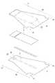
側面形状が三角形状(主として直角三角形状)あるいはこれに類似する形状で、所定の厚みないし幅を有する立体形状に仕上げられたサンドイッチ等の食品を包装するための食品用包装袋は、図11に示す形態のものが一般的であり、新しいものでは、特許文献1に記載されたものが公知である。 FIG. 11 shows a food packaging bag for packaging food such as sandwiches having a triangular shape (mainly a right-angled triangular shape) or a similar shape on the side surface and finished in a three-dimensional shape having a predetermined thickness or width. The ones shown are generally the ones shown, and the new ones described in
かかる食品用包装袋1’は、一端側よりも他端側が幅広となる形状を有する一対のシート2’,3’が重ね合わされ、一端側の頂部接合部11’と両側縁の側部接合部12’,12’により三方が封止されて他端側が開口部13’となる袋本体10’を備えるものであり、開口部13’の両角部には、該角部を斜め直線状に切り落とすことで、切欠部14’、14’が形成される。 In such a food packaging bag 1', a pair of sheets 2', 3'having a shape in which the other end side is wider than one end side are overlapped, and the top joint portion 11'on one end side and the side joint portion on both side edges are overlapped. It is provided with a bag body 10'in which three sides are sealed by 12'and 12'and the other end side is an opening 13', and the corners are cut off in an oblique straight line at both corners of the opening 13'. As a result, the notches 14'and 14' are formed.
また、食品の生産数量が多いために食品用包装袋を多く必要とする生産者に対しては、図12に示す如く、裏シート3’の他端に、切り離し線30’を介して耳片31’を接続した形態にするとともに、複数の食品用包装袋1’,…をきれいに揃えた状態で、複数の耳片31’,…を適宜の箇所で接合(接合部32’)して、複数の食品用包装袋1’,…を束体にして提供することが一般的である。 Further, for producers who require a large amount of food packaging bags due to a large production quantity of food, as shown in FIG. 12, an ear piece is provided at the other end of the back sheet 3'with a separating line 30'. In a form in which 31'is connected, and in a state where a plurality of food packaging bags 1', ... Are neatly arranged, a plurality of ear pieces 31', ... Are joined at appropriate points (joint portion 32'). It is common to provide a plurality of food packaging bags 1', ... As a bundle.
食品の包装に際しては、耳片31’に形成された挿通孔33’に、図13(a)に示す如く、ピンPを通して、束体を包装装置(図示しない)にセットする。次に、ブロワ(図示しない)で開口部13’から袋本体10’内に所定圧の空気を吹き込み、あるいは、吸引ヘッド(図示しない)で表シート2’の開口部13’側を吸引して持ち上げる等して、開口部13’を開く。そして、この状態で食品Fを袋本体10’内に挿入する。 When packaging food, the bundle is set in a packaging device (not shown) through a pin P as shown in FIG. 13A in the insertion hole 33'formed in the ear piece 31'. Next, air of a predetermined pressure is blown into the bag body 10'from the opening 13'with a blower (not shown), or the opening 13'side of the front sheet 2'is sucked with a suction head (not shown). Open the opening 13'by lifting or the like. Then, in this state, the food F is inserted into the bag body 10'.
食品Fを袋本体10’内に収容すると、同図(b)に示す如く、食品用包装袋1’を束体から切り離し、さらに、同図(c)に示す如く、開口部13’の余分なシート片を折り畳んで食品用包装袋1’の開口部13’を閉塞した後、ラベル又はテープ4’を貼着して開口部13’を封止する。これにより、食品包装体が完成する。 When the food F is housed in the bag body 10', the food packaging bag 1'is separated from the bundle as shown in FIG. 3B, and the extra opening 13'is further separated as shown in FIG. The sheet piece is folded to close the opening 13'of the food packaging bag 1', and then a label or tape 4'is attached to seal the opening 13'. This completes the food packaging.
しかしながら、従来の食品用包装袋においては、開口部13’を開く際や開口部13’を開いている間、表シート2’の開口部13’側が持ち上がることにより、表シート2’に上向きの力が加わることで、図14に示す如く、表シート2’と裏シート3’の境界である側部接合部12’のうち、とりわけ端点12a’に引張力Tが作用する。側部接合部12’は、通常、溶断シールであるため、線状シールであり、接合強度は高くない。したがって、側部接合部12’の端点12a’に引張力Tが作用すると、そこから側部接合部12’が剥離して、開裂が発生するという問題がある。 However, in the conventional food packaging bag, when the opening 13'is opened or while the opening 13'is opened, the opening 13'side of the front sheet 2'is lifted, so that the front sheet 2'is upward. When the force is applied, as shown in FIG. 14, the tensile force T acts on the end point 12a'of the side joint portion 12', which is the boundary between the front sheet 2'and the back sheet 3'. Since the side joint portion 12'is usually a fusing seal, it is a linear seal and the joint strength is not high. Therefore, when a tensile force T acts on the end point 12a'of the side joint portion 12', the side joint portion 12'is peeled off from the
そこで、本発明は、かかる事情に鑑みてなされたもので、開口部を開いても側部接合部に開裂が生じにくい食品用包装袋を提供することを課題とする。 Therefore, the present invention has been made in view of such circumstances, and an object of the present invention is to provide a food packaging bag in which tearing is unlikely to occur at the side joint portion even if the opening is opened.
本発明に係る食品用包装袋は、
一端側よりも他端側が幅広となる形状を有する一対のシートが重ね合わされ、一端側の頂部接合部と両側縁の側部接合部により三方が封止されて他端側が開口部となる袋本体を備える食品用包装袋において、
袋本体は、開口部の角部に切欠部を備え、
切欠部は、
切欠部によって形成される側部接合部の端点を始点とする第1の外形線であって、側部接合部の端点における第1の外形線の接線が側部接合部の端点における袋本体の側縁の接線に対して略直角又は鈍角となる第1の外形線と、
第1の外形線の終点を始点とし、袋本体の一端側に凹となる第2の外形線と
を備えて構成され、
第1の外形線の始点は、第2の外形線に接する袋本体の側縁の法線よりも袋本体の他端側に位置する
食品用包装袋である。The food packaging bag according to the present invention is
A pair of sheets having a shape in which the other end side is wider than the one end side are overlapped, and the bag body is sealed on three sides by the top joint portion on the one end side and the side joint portions on both sides, and the other end side is an opening. In a food packaging bag equipped with
The bag body has a notch at the corner of the opening,
The notch is
The first outline starting from the end point of the side joint formed by the notch, and the tangent line of the first outline at the end point of the side joint is the end point of the bag body at the end point of the side joint. The first outline, which is approximately perpendicular or obtuse to the tangent of the side edge,
It is configured with a second outline that is concave on one end side of the bag body, starting from the end point of the first outline.
The starting point of the first outline is located on the other end side of the bag body with respect to the normal of the side edge of the bag body in contact with the second outline.
It is a food packaging bag.
また、本発明に係る食品用包装袋は、Further, the food packaging bag according to the present invention is
一端側よりも他端側が幅広となる形状を有する一対のシートが重ね合わされ、一端側の頂部接合部と両側縁の側部接合部により三方が封止されて他端側が開口部となる袋本体を備える食品用包装袋において、A pair of sheets having a shape in which the other end side is wider than the one end side are overlapped, and the bag body is sealed on three sides by the top joint portion on the one end side and the side joint portions on both sides, and the other end side is an opening. In a food packaging bag equipped with
袋本体は、開口部の角部に切欠部を備え、The bag body has a notch at the corner of the opening,
切欠部は、The notch is
切欠部によって形成される側部接合部の端点を始点とする第1の外形線であって、側部接合部の端点における第1の外形線の接線が側部接合部の端点における袋本体の側縁の接線に対して略直角又は鈍角となる第1の外形線と、The first outline starting from the end point of the side joint formed by the notch, and the tangent line of the first outline at the end point of the side joint is the end point of the bag body at the end point of the side joint. The first outline, which is approximately perpendicular or obtuse to the tangent of the side edge,
第1の外形線の終点を始点とし、袋本体の一端側に凹となる第2の外形線とStarting from the end point of the first outline, and the second outline that is concave on one end side of the bag body.
を備えて構成され、Is configured with
第1の外形線の始点は、第2の外形線に接する袋本体の側縁の法線よりも袋本体の一端側に位置するThe starting point of the first outline is located on one end side of the bag body with respect to the normal of the side edge of the bag body in contact with the second outline.
食品用包装袋である。It is a food packaging bag.
また、本発明に係る食品用包装袋は、Further, the food packaging bag according to the present invention is
一端側よりも他端側が幅広となる形状を有する一対のシートが重ね合わされ、一端側の頂部接合部と両側縁の側部接合部により三方が封止されて他端側が開口部となる袋本体を備える食品用包装袋において、A pair of sheets having a shape in which the other end side is wider than the one end side are overlapped, and the bag body is sealed on three sides by the top joint portion on the one end side and the side joint portions on both sides, and the other end side is an opening. In a food packaging bag equipped with
袋本体は、開口部の角部に切欠部を備え、The bag body has a notch at the corner of the opening,
切欠部は、The notch is
切欠部によって形成される側部接合部の端点を始点とする第1の外形線であって、側部接合部の端点における第1の外形線の接線が側部接合部の端点における袋本体の側縁の接線に対して略直角又は鈍角となる第1の外形線と、The first outline starting from the end point of the side joint formed by the notch, and the tangent line of the first outline at the end point of the side joint is the end point of the bag body at the end point of the side joint. The first outline, which is approximately perpendicular or obtuse to the tangent of the side edge,
第1の外形線の終点を始点とし、袋本体の一端側に凹となる第2の外形線とStarting from the end point of the first outline, and the second outline that is concave on one end side of the bag body.
を備えて構成され、Is configured with
第2の外形線に接する袋本体の側縁の法線から袋本体の他端側に突出する凸部の最大突出量は、10mm以下であるThe maximum amount of protrusion of the convex portion protruding from the normal of the side edge of the bag body in contact with the second outer line to the other end side of the bag body is 10 mm or less.
食品用包装袋である。It is a food packaging bag.
これらの構成によれば、開口部を開く際や開口部を開いている間に開口部に生じる引張力は、主として切欠部の外形線に作用するようになるため、側部接合部の端点には作用しにくくなる。したがって、開口部を開いても、側部接合部の端点には、側部接合部を剥離する力は作用せず、側部接合部の開裂は生じにくい。According tothese configurations, the tensile force generated in the opening when opening the opening or while opening the opening mainly acts on the outline of the notch, so that it is applied to the end point of the side joint. Becomes less likely to work. Therefore, even if the opening is opened, the force for peeling the side joint does not act on the end point of the side joint, and the side joint is unlikely to be cleaved.
以上の如く、本発明に係る食品用包装袋によれば、切欠部の外形線を上記の形状とすることで、開口部を開く際や開口部を開いている間に開口部に生じる引張力が側部接合部の端点に作用しにくくなるため、開口部を開いた際に側部接合部に開裂が生じるのを好適に防止することができる。 As described above, according to the food packaging bag according to the present invention, by making the outline of the cutout portion into the above-mentioned shape, the tensile force generated in the opening portion when opening the opening portion or while opening the opening portion. Is less likely to act on the end points of the side joints, so that it is possible to preferably prevent the side joints from being cracked when the opening is opened.
<第1の実施形態>
以下、本発明に係る食品用包装袋の第1の実施形態として、サンドイッチの包装に用いられる食品用包装袋について、図1ないし図6を参酌して説明する。<First Embodiment>
Hereinafter, as the first embodiment of the food packaging bag according to the present invention, the food packaging bag used for sandwich packaging will be described with reference to FIGS. 1 to 6.
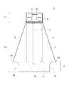
図1ないし図3に示す如く、本実施形態に係る食品用包装袋1は、一端側よりも他端側が幅広となる形状を有する一対のシート(表シート2、裏シート3)が重ね合わされ、一端側の頂部接合部11と両側縁の側部接合部12,12により三方が封止されて他端側が開口部13となる袋本体10と、一対のシート2,3のうち、頂部接合部11から突出する一対の突出片で構成されるヘッダ部17とを備える。 As shown in FIGS. 1 to 3, in the
表シート2は、ポリエチレンやポリプロピレン等の熱溶着性を有するプラスチックシートからなり、一端側から他端側に向かって漸次幅広となる形状の胴部20と、該胴部20の一端から延びる幅狭の先端部21(上記突出片となる)とを備えて構成される。 The
裏シート3も、ポリエチレンやポリプロピレン等の熱溶着性を有するプラスチックシートからなり、一端側から他端側に向かって漸次幅広となる形状の胴部30と、該胴部30の一端から延びる幅狭の先端部31(上記突出片となる)とを備えて構成される。 The
本実施形態においては、胴部20,30は、台形状ないし略台形状であり、先端部21,31は、矩形状ないし略矩形状である。そのため、胴部20,30の一端(及びこれに一致する先端部21,31の他端)は、一端側から他端側に向かう方向(以下、「長手方向」という。」に対して直交する直線状であり、言い換えれば、長手方向と直交する方向(以下、「幅方向」という。)と平行な直線状であり、胴部20,30の両側縁は、長手方向に対して傾斜する直線状であり、先端部21,31の両側縁は、長手方向と平行な直線状である。ただし、胴部20,30の両側縁の他端側は、切欠部14によって欠如しており、胴部20,30の他端側は、切欠部14の分だけ幅狭とされる。 In the present embodiment, the
頂部接合部11は、胴部20,30の一端に沿って表シート2及び裏シート3をヒートシールすることにより形成される。側部接合部12は、胴部20,30の側縁(斜辺)及び先端部21,31の側縁(縦辺)をヒートシールすることにより形成される。ただし、頂部接合部11は、例えばヒートシールバーを用いた溶着により形成されることにより、長手方向に所定の幅を有する帯状シールとなっているのに対し、側部接合部12は、溶断により形成されることにより、線シールとなっている。具体的には、頂部接合部11は、数ミリ以上の幅を有するのに対し、側部接合部12の幅は、1mm以下である。 The top
このようにして構成された袋本体10の内部が食品の収容部となるが、袋本体10における表フィルム2の内面には、内シート4が貼着される。内シート4は、例えば他端部が二箇所でポイントシール等により接合され(接合部22)、一端側が自由端となっている。これにより、収容部内で食品が動いたとしても、内シート4が食品の表面に密着してその動きに追従するため、表シート2が汚れることがなく、外観が損なわれることがない。 The inside of the
ヘッダ部17における裏シート3の内面には、切込線32が形成される。切込線32は、全切線、半切線(ハーフカット)、ミシン目等によってU字形、半円形、V字形、X字形、十字形、-字形等に形成され、切込線32の形成によって開封起点としての摘み部33が形成される。そして、摘み部33から裏シート3の他端側にかけて開封案内手段5が設けられる。開封案内手段5は、例えば、裏シート3の内面に貼着されるカットテープや、一対のハーフカットや糸等である。これにより、摘み部33を引き下ろすことにより、開封案内手段5が所定の幅で裏シート3を切断し、開封することができる。 A
開口部13の角部には、切欠部14が形成される。切欠部14は、側部接合部12を除去して、開口部13における表シート2と裏シート3の分離性を高め、開口部13の開口操作を容易にするためのものである。 A
図4に示す如く、切欠部14は、切欠部14によって形成された側部接合部12の端点12aを始点とする第1の外形線14Aと、第1の外形線14Aの終点14aを始点とする第2の外形線14Bと、第2の外形線14Bの終点14bを始点とし、袋本体10の開口端縁(幅方向(長手方向と直交する方向)に沿った開口部13の端縁)13Aに交わる点を終点14cとする第3の外形線14Cで構成される。 As shown in FIG. 4, the
同図(a)に示す如く、第1の外形線14Aは、側部接合部12の端点12aにおける第1の外形線14Aの接線T1と、側部接合部12の端点12aにおける袋本体10の側縁の接線T2(側縁は直線なので、接線T2は側縁と一致する)との交差角θ1が直角以上となる線である。第2の外形線14Bは、第1の外形線14Aの終点14aにおける第2の外形線14Bの接線T3と、幅方向(長手方向と直交する方向)に延びる線H1との交差角θ2が鋭角となる線である。第3の外形線14Cは、第2の外形線14Bの終点14bにおける第3の外形線14Cの接線T4と、幅方向(長手方向と直交する方向)に延びる線H1との交差角θ3が直角以下となる線である。 As shown in FIG. 3A, the
同図(b)に示す如く、第1の外形線14Aは、袋本体10の他端側に凸となる線であり、所定の曲率半径R1を有する曲線である。第2の外形線14Bは、袋本体10の一端側に凹となる線であり、所定の曲率半径R2を有する曲線である。本実施形態においては、曲率半径R1より曲率半径R2が大きく設定される。第3の外形線14Cは、直線である。また、第1の外形線14Aは、同図(c)に示す如く、側部接合部12の端点12aを通る袋本体10の側縁の法線P3よりも袋本体10の他端側に凸となる線である。第2の外形線14Bは、第1の外形線14Aに接する袋本体10の側縁の法線P2よりも袋本体10の一端側に凹となる線である。また、第2の外形線14Bは、側部接合部12の端点12aを通る袋本体10の側縁の法線P3よりも袋本体10の一端側に凹となる線である。 As shown in FIG. 3B, the
同図(c)に示す如く、第1の外形線14Aは、第2の外形線14Bに接する袋本体10の側縁の法線P1から第1の外形線14Aまでの最大距離L1、言い換えれば、法線P1から袋本体10の他端側に突出する凸部15の最大突出量L1、が所定範囲に収まるように設定される。本実施形態においては、最大距離ないし最大突出量L1は、10mm以下、より好ましくは、8mm以下である。 As shown in FIG. 3C, the
法線P1は、袋本体10の側縁との交点12bが側部接合部12上に位置する線となっている。これにより、第1及び第2の外形線14A,14Bのうち、第1の外形線14Aの始点12aから第2の外形線14B上の法線P1の接点にかけてのすべての部分が、法線P1よりも袋本体10の他端側に突出した位置にある。 The normal vector P1 is a line in which the
本実施形態に係る食品用包装袋は、以上の構成からなり、次に、本実施形態に係る食品用包装袋を用いた食品の包装方法について説明する。概略は、〔背景技術〕欄で説明したとおりである。 The food packaging bag according to the present embodiment has the above configuration, and then a method for packaging food using the food packaging bag according to the present embodiment will be described. The outline is as explained in the [Background Technique] column.
まず、図13(a)に示す如く、ピンPを通して、本実施形態に係る食品用包装袋を複数束ねて形成した束体を包装装置(図示しない)にセットする。次に、ブロワ(図示しない)で開口部13から袋本体10内に所定圧の空気を吹き込み、あるいは、吸引ヘッド(図示しない)で表シート2の開口部13側を吸引して持ち上げる等して、開口部13を開く。そして、この状態で食品Fを袋本体10内に挿入する。 First, as shown in FIG. 13A, a bundle formed by bundling a plurality of food packaging bags according to the present embodiment is set in a packaging device (not shown) through a pin P. Next, air of a predetermined pressure is blown into the
食品Fを袋本体10内に収容すると、同図(b)に示す如く、食品用包装袋1を束体から切り離す。なお、食品Fを袋本体10内に収容すると、開口部13の開口形状は、長方形状ないし略長方形状となり、また、表シート2及び裏シート3の各側部接合部12に跨った部分が一対の対向する三角形状ないし略三角形状の側面部となり、表シート2の中間部分が長方形状ないし略長方形状の正面部となり、裏シート3の中間部分が長方形状ないし略長方形状の背面部となる。 When the food F is housed in the bag
次に、同図(c)に示す如く、開口部13の余分なシート片を折り畳んで食品用包装袋1の開口部13を閉塞する。シート片を折り畳む順序は、まず、背面部のシート片を内側に折り畳み、次に、側面部のシート片を内側に折り畳み、最後に、正面部のシート片を内側に折り畳む。ただし、まず、正面部のシート片を折り畳み、次に、側面部のシート片を折り畳み、最後に、背面部のシート片を折り畳むとか、まず、背面部又は正面部の一方のシート片を折り畳み、次に、他方のシート片を折り畳み、最後に、側面部のシート片を折り畳むとか、まず、側面部のシート片を折り畳み、次に、背面部又は正面部の一方のシート片を折り畳み、最後に、他方のシート片を折り畳む等、四つのシート片を折り畳む順序は特に限定されない。 Next, as shown in FIG. 3C, the extra sheet piece of the
開口部13を閉塞すると、ラベルを貼着して開口部13を封止する。あるいは、テープを貼着したり、フィルム片の折り畳んで重なり合った所定箇所をヒートシール等で接合して、開口部13を封止するようにしてもよい。これにより、食品包装体が完成する。そして、食品包装体は、頂部接合部11、一対の側部接合部12,12、及び封緘された開口部13の閉塞部(底面部)によって気密状態に維持される。このため、外気等が内部に侵入することはなく、包装された食品は、所期の品質が維持される。 When the
次に、本実施形態に係る食品用包装袋の特徴について説明する。 Next, the features of the food packaging bag according to the present embodiment will be described.
〔発明が解決しようとする課題〕欄でも説明したとおり、食品を食品用包装袋1内に挿入するに際しては、図13(a)に示す如く、開口部13を開くことで、表シート2に上向きの力が加わり、表シート2と裏シート3に対して引張力Tが発生する。しかし、本実施形態に係る食品用包装袋においては、開口部13の角部の切欠部14の形状が、上述した、第1の外形線14A、第2の外形線14B及び第3の外形線14Cの三つの連続した外形線で構成される。これにより、図5(a)に示す如く、引張力Tは、主として第2の外形線14Bに作用することとなり、側部接合部12の端点12aに作用しにくくなる。このため、本実施形態に係る食品用包装袋によれば、開口部13を開いた際に側部接合部12に開裂が生じるのを好適に防止することができる。 As explained in the [Problems to be Solved by the Invention] column, when the food is inserted into the
しかも、第1の外形線14Aは、側部接合部12の端点12aにおける第1の外形線14Aの接線T1と、側部接合部12の端点12aにおける袋本体10の側縁の接線T2との交差角θ1が直角以上となる線であるため、側部接合部12の端点12a付近の切欠部14の外形線によって形成される凸部15(同図(b)に示す、一対の第2の外形線14B,14Bの接線から突出する凸部15)は、なだらかな形状となる。仮に、図6(a)に示す如く、交差角θ1が鋭角であるとすると、同図(b)に示す如く、側部接合部12の端点12a付近の切欠部14の外形線によって形成される凸部15’は尖った形状となる。この尖った凸部15’は、引張力Tが第2の外形線14B’に作用することにより、袋本体10の内側に折れ曲がりやすくなる。そうすると、食品を挿入する際、この折れ曲がった尖った凸部15’が食品に引っかかって、開口形状が崩れ、挿入不良を引き起こす可能性がある。また、折れ曲がった尖った凸部15’がシートの内面に当たり、シートに傷が入ることも懸念される。しかし、なだらかな凸部15であれば、このような問題はない。 Moreover, the first
また、図6に示した比較例の凸部15’は、そもそも、先端が角ばっているため、腰感がなく、折れ曲がりやすいが、本実施形態に係る食品用包装袋の凸部15は、面積が広いため、腰感があり、折れ曲がりにくくなっている。 Further, since the convex portion 15'of the comparative example shown in FIG. 6 has a square tip, it does not have a feeling of waist and is easily bent. However, the
ただし、なだらかな凸部15であっても、引張力Tが第2の外形線14Bに作用することにより、袋本体10の内側に折れ曲がるという事象は起こり得る。そこで、袋本体10の内側への突出量が大きくならないよう、上述のとおり、第2の外形線14Bに接する袋本体10の側縁の法線P1から第1の外形線14Aまでの最大距離L1(図4(c)、図5(b))は、10mm以下、より好ましくは、8mm以下とする(尖った凸部15’の折れ曲がり角度は、70~90°くらいになり得るが、なだらかな凸部15の場合は、その形状上、折れ曲がり角度は大きくはないため、袋本体10の内側への突出量は10mmや8mmといった大きさにはならない。)。 However, even in the case of the gentle
このように、本実施形態に係る食品用包装袋によれば、開口部13を開く際や開口部13を開いている間に開口部13に生じる引張力Tが側部接合部12の端点12aに作用しにくくなるため、開口部13を開いた際に側部接合部12に開裂が生じることはなく、また、開口部13には、食品を袋内に挿入する際に食品が引っかかってしまう部位が生じないため、食品の挿入不良が生じることもない。 As described above, according to the food packaging bag according to the present embodiment, the tensile force T generated in the
<第2の実施形態>
次に、本発明に係る食品用包装袋の第2の実施形態として、サンドイッチの包装に用いられる食品用包装袋について、図7を参酌して説明する。なお、第一の実施形態との違いは、切欠部14の形状(特に、第1の外形線14Aの形状)のみであり、その他の構成は同じなので、同じ構成についての説明は省略する。<Second embodiment>
Next, as a second embodiment of the food packaging bag according to the present invention, the food packaging bag used for sandwich packaging will be described with reference to FIG. 7. The only difference from the first embodiment is the shape of the notch 14 (particularly, the shape of the
第一の実施形態においては、図4(c)に示す如く、第1の外形線14Aの始点(側部接合部12の端点12a)は、第2の外形線14Bに接する袋本体10の側縁の法線P1よりも袋本体10の他端側に位置しており、そのため、図5(b)に示す如く、法線P1(一対の第2の外形線14B,14Bの接線)から突出するなだらかな凸部15は一つである。これに対し、第二の実施形態においては、図7(a)に示す如く、第1の外形線14Aの始点(側部接合部12の端点12a)は、第2の外形線14Bに接する袋本体10の側縁の法線P1よりも袋本体10の一端側に位置しており、言い換えれば、法線P1の袋本体10の側縁との交点12bは、側部接合部12の延長線上に位置しており、そのため、同図(b)に示す如く、法線P1(一対の第2の外形線14B,14Bの接線)から突出するなだらかな凸部15は、側部接合部12を挟んで左右二つとなる。 In the first embodiment, as shown in FIG. 4C, the start point of the
この場合、なだらかな凸部15を袋本体10の内側に折り曲げる作用力は、第一の実施形態の場合に比べて小さくなる。したがって、第二の実施形態に係る食品用包装袋によっても、開口部13を開く際や開口部13を開いている間に開口部13に生じる引張力Tが側部接合部12の端点12aに作用しにくくなるため、開口部13を開いた際に側部接合部12に開裂が生じることはなく、かつ、食品の挿入円滑性がさらに向上する。 In this case, the acting force for bending the gentle
なお、本発明に係る食品用包装袋は、上記実施形態に限定されるものではなく、本発明の要旨を逸脱しない範囲で種々の変更が可能である。 The food packaging bag according to the present invention is not limited to the above embodiment, and various modifications can be made without departing from the gist of the present invention.
例えば、上記実施形態においては、袋本体10の側縁及び側部接合部12は、直線状であった。しかし、袋本体10の側縁及び側部接合部12は、図8(a)に示す如く、外側に膨らむ曲線であったり、同図(b)に示す如く、内側に凹となる曲線であってもよい。 For example, in the above embodiment, the side edge and the side
また、上記実施形態においては、切欠部14の第1の外形線14A及び第2の外形線14bは、曲線であった。しかし、例えば、図9(a)に示す如く、第1の外形線14Aは、直線状であってもよく、同図(b)に示す如く、第2の外形線14Bは、直線によって構成される線(不連続点を有する曲線)であってもよく、同図(c)に示す如く、第1の外形線14A及び第2の外形線14bは、直線によって構成される線(不連続点を有する曲線)であってもよく、あるいは、直線と曲線を適宜組み合わせた線であってもよい。 Further, in the above embodiment, the first
なお、図9(a)に示す第1の外形線14Aは、交差角θ1が直角よりも小さいが、これは本発明に係る「略直角」に含まれるものである。具体的には、交差角θ1は、80°以上であれば、尖った凸部とはならないので、「略直角」とは、80°以上を含むものである。 The
また、上記実施形態においては、切欠部14の第3の外形線14Cは、第2の外形線14Bの終点14bにおける第3の外形線14Cの接線T4と、幅方向(長手方向と直交する方向)に延びる線H1との交差角θ3が直角の線であった。しかし、図9(d)に示す如く、交差角θ3は、鋭角であり、第3の外形線14Cは、袋本体10の他端側ほど幅方向中心に近づく傾斜した線であってもよい。 Further, in the above embodiment, the third
また、上記実施形態においては、開口部13の左右の角部のそれぞれに切欠部14が形成されるものであった。しかし、側部接合部12の開裂の問題が左右の側部接合部12の片側だけに生じるものであるのであれば(例えば、開口部13の中心から空気が吹き込まれるのではなく、左右のいずれかに片寄った位置から空気が吹き込まれる等して、開口部13を開く力が左右均等でないような場合とか、表シート2の開口部13側の吸引箇所が左右のいずれかに片寄った位置である場合等)、例えば、図10(a)に示す如く、一方の角部にだけ切欠部14を形成するとか、同図(b)に示す如く、他方の角部には通常の切欠部14’を形成するとか、同図(c)に示す如く、左右の切欠部14の大きさや形状を変えるようにしてもよい。 Further, in the above embodiment, the
また、上記実施形態においては、切欠部14の第1の外形線14Aと第2の外形線14Bを曲線に形成する場合に、第1の外形線14Aの曲率半径R1より第2の外形線14Bの曲率半径R2が大きく設定された。しかし、この逆であってもよいし、あるいは同じ曲率半径であってもよい。 Further, in the above embodiment, when the first
また、上記実施形態においては、食品はサンドイッチであった。しかし、食品用包装袋に収容できる形であれば、パン、ケーキ、カステラ、おにぎり等の米飯加工食品等、食品の種類は限定されない。 Further, in the above embodiment, the food was a sandwich. However, the type of food is not limited as long as it can be stored in a food packaging bag, such as processed rice foods such as bread, cakes, castella, and rice balls.
1…食品用包装袋、10…袋本体、11…頂部接合部、12…側部接合部、12a…端点(第1の外形線の始点)、12b…交点、13…開口部、13A…開口端縁、14…切欠部、14A…第1の外形線、14a…第1の外形線の終点(第2の外形線の始点)、14B…第2の外形線、14b…第2の外形線の終点(第3の外形線の始点)、14C…第3の外形線、14c…第3の外形線の終点、15…凸部、17…ヘッダ部、2…表シート、20…胴部、21…先端部、22…接合部、3…裏シート、30…胴部、31…先端部、32…切込線、33…開封起点、4…内シート、5…開封案内手段、F…食品、T…張力、T1~T3…接線、H1…線、θ1~θ3…交差角、R1,R2…曲率半径、P1~P3…法線、L1…最大距離 1 ... Food packaging bag, 10 ... Bag body, 11 ... Top joint, 12 ... Side joint, 12a ... End point (starting point of first outline), 12b ... Intersection, 13 ... Opening, 13A ... Opening Edge, 14 ... notch, 14A ... first outline, 14a ... end point of first outline (start point of second outline), 14B ... second outline, 14b ... second outline End point (start point of the third outline), 14C ... third outline, 14c ... end point of the third outline, 15 ... convex part, 17 ... header part, 2 ... front sheet, 20 ... body part, 21 ... Tip, 22 ... Joint, 3 ... Back sheet, 30 ... Body, 31 ... Tip, 32 ... Cut line, 33 ... Opening starting point, 4 ... Inner sheet, 5 ... Opening guide means, F ... Food , T ... tension, T1 to T3 ... tangent, H1 ... line, θ1 to θ3 ... intersection angle, R1, R2 ... radius of curvature, P1 to P3 ... normal, L1 ... maximum distance
Claims (3)
Translated fromJapanese前記袋本体は、前記開口部の角部に切欠部を備え、
該切欠部は、
該切欠部によって形成される前記側部接合部の端点を始点とする第1の外形線であって、前記側部接合部の前記端点における第1の外形線の接線が前記側部接合部の前記端点における前記袋本体の前記側縁の接線に対して略直角又は鈍角となる第1の外形線と、
該第1の外形線の終点を始点とし、前記袋本体の一端側に凹となる第2の外形線と
を備えて構成され、
前記第1の外形線の前記始点は、前記第2の外形線に接する前記袋本体の前記側縁の法線よりも前記袋本体の他端側に位置する
食品用包装袋。A pair of sheets having a shape in which the other end side is wider than the one end side are overlapped, and the bag body is sealed on three sides by the top joint portion on the one end side and the side joint portions on both sides, and the other end side is an opening. In a food packaging bag equipped with
The bag body is provided with a notch at the corner of the opening.
The notch is
The first outline starting from the end point of the side joint formed by the notch, and the tangent of the first outline at the end of the side joint is the side joint. A first outline that is substantially perpendicular or obtuse to the tangent to the side edge of the bag body at the end point,
Starting from the end point of the first outline, a second outline that is concave on one end side of the bag body is provided.
The starting point of the first outline is located on the other end side of the bag body with respect to the normal of the side edge of the bag body in contact with the second outline.
Food packaging bag.
前記袋本体は、前記開口部の角部に切欠部を備え、
該切欠部は、
該切欠部によって形成される前記側部接合部の端点を始点とする第1の外形線であって、前記側部接合部の前記端点における第1の外形線の接線が前記側部接合部の前記端点における前記袋本体の前記側縁の接線に対して略直角又は鈍角となる第1の外形線と、
該第1の外形線の終点を始点とし、前記袋本体の一端側に凹となる第2の外形線と
を備えて構成され、
前記第1の外形線の前記始点は、前記第2の外形線に接する前記袋本体の前記側縁の法線よりも前記袋本体の一端側に位置する
食品用包装袋。A pair of sheets having a shape in which the other end side is wider than the one end side are overlapped, and the bag body is sealed on three sides by the top joint portion on the one end side and the side joint portions on both sides, and the other end side is an opening. In a food packaging bag equipped with
The bag body is provided with a notch at the corner of the opening.
The notch is
The first outline starting from the end point of the side joint formed by the notch, and the tangent of the first outline at the end of the side joint is the side joint. A first outline that is substantially perpendicular or obtuse to the tangent to the side edge of the bag body at the end point,
Starting from the end point of the first outline, and the second outline that is concave on one end side of the bag body.
Is configured with
The starting point of the first outline is located on one end side of the bag body with respect to the normal of the side edge of the bag body in contact with the second outline.
Food packaging bag.
前記袋本体は、前記開口部の角部に切欠部を備え、
該切欠部は、
該切欠部によって形成される前記側部接合部の端点を始点とする第1の外形線であって、前記側部接合部の前記端点における第1の外形線の接線が前記側部接合部の前記端点における前記袋本体の前記側縁の接線に対して略直角又は鈍角となる第1の外形線と、
該第1の外形線の終点を始点とし、前記袋本体の一端側に凹となる第2の外形線と
を備えて構成され、
前記第2の外形線に接する前記袋本体の前記側縁の法線から前記袋本体の他端側に突出する凸部の最大突出量は、10mm以下である
食品用包装袋。A pair of sheets having a shape in which the other end side is wider than the one end side are overlapped, and the bag body is sealed on three sides by the top joint portion on the one end side and the side joint portions on both sides, and the other end side is an opening. In a food packaging bag equipped with
The bag body is provided with a notch at the corner of the opening.
The notch is
The first outline starting from the end point of the side joint formed by the notch, and the tangent of the first outline at the end of the side joint is the side joint. A first outline that is substantially perpendicular or obtuse to the tangent to the side edge of the bag body at the end point,
Starting from the end point of the first outline, and the second outline that is concave on one end side of the bag body.
Is configured with
The maximum amount of protrusion of the convex portion protruding from the normal of the side edge of the bag body in contact with the second outer line to the other end side of the bag body is 10 mm or less.
Food packaging bag.
Priority Applications (1)
| Application Number | Priority Date | Filing Date | Title |
|---|---|---|---|
| JP2018109017AJP7101049B2 (en) | 2018-06-06 | 2018-06-06 | Food packaging bag |
Applications Claiming Priority (1)
| Application Number | Priority Date | Filing Date | Title |
|---|---|---|---|
| JP2018109017AJP7101049B2 (en) | 2018-06-06 | 2018-06-06 | Food packaging bag |
Publications (2)
| Publication Number | Publication Date |
|---|---|
| JP2019210022A JP2019210022A (en) | 2019-12-12 |
| JP7101049B2true JP7101049B2 (en) | 2022-07-14 |
Family
ID=68846279
Family Applications (1)
| Application Number | Title | Priority Date | Filing Date |
|---|---|---|---|
| JP2018109017AActiveJP7101049B2 (en) | 2018-06-06 | 2018-06-06 | Food packaging bag |
Country Status (1)
| Country | Link |
|---|---|
| JP (1) | JP7101049B2 (en) |
Families Citing this family (42)
| Publication number | Priority date | Publication date | Assignee | Title |
|---|---|---|---|---|
| JP4989309B2 (en) | 2007-05-18 | 2012-08-01 | 株式会社半導体エネルギー研究所 | Liquid crystal display |
| US9041202B2 (en) | 2008-05-16 | 2015-05-26 | Semiconductor Energy Laboratory Co., Ltd. | Semiconductor device and manufacturing method of the same |
| US8314765B2 (en) | 2008-06-17 | 2012-11-20 | Semiconductor Energy Laboratory Co., Ltd. | Driver circuit, display device, and electronic device |
| KR101803264B1 (en) | 2008-09-19 | 2017-12-28 | 가부시키가이샤 한도오따이 에네루기 켄큐쇼 | Semiconductor device |
| TWI606595B (en) | 2008-11-07 | 2017-11-21 | 半導體能源研究所股份有限公司 | Semiconductor device and method of manufacturing same |
| US8232947B2 (en) | 2008-11-14 | 2012-07-31 | Semiconductor Energy Laboratory Co., Ltd. | Liquid crystal display device |
| US8461582B2 (en) | 2009-03-05 | 2013-06-11 | Semiconductor Energy Laboratory Co., Ltd. | Semiconductor device and method for manufacturing the same |
| KR101752640B1 (en) | 2009-03-27 | 2017-06-30 | 가부시키가이샤 한도오따이 에네루기 켄큐쇼 | Semiconductor device |
| KR102011616B1 (en) | 2009-06-30 | 2019-08-16 | 가부시키가이샤 한도오따이 에네루기 켄큐쇼 | Method for manufacturing semiconductor device |
| KR101772639B1 (en) | 2009-10-16 | 2017-08-29 | 가부시키가이샤 한도오따이 에네루기 켄큐쇼 | Semiconductor device |
| CN107731931B (en) | 2009-10-21 | 2021-03-23 | 株式会社半导体能源研究所 | Display device and electronic equipment including display device |
| KR101849321B1 (en) | 2009-11-06 | 2018-04-16 | 가부시키가이샤 한도오따이 에네루기 켄큐쇼 | Semiconductor device and manufacturing method thereof |
| KR102257564B1 (en) | 2009-12-18 | 2021-05-31 | 가부시키가이샤 한도오따이 에네루기 켄큐쇼 | Driving method of display device and display device |
| KR102352590B1 (en) | 2009-12-18 | 2022-01-17 | 가부시키가이샤 한도오따이 에네루기 켄큐쇼 | Liquid crystal display device and electronic device |
| KR20250048807A (en) | 2009-12-25 | 2025-04-10 | 가부시키가이샤 한도오따이 에네루기 켄큐쇼 | Semiconductor device |
| KR102542681B1 (en) | 2010-01-20 | 2023-06-14 | 가부시키가이샤 한도오따이 에네루기 켄큐쇼 | Electronic device |
| KR20190093706A (en) | 2010-01-24 | 2019-08-09 | 가부시키가이샤 한도오따이 에네루기 켄큐쇼 | Display device and manufacturing method thereof |
| US8947337B2 (en) | 2010-02-11 | 2015-02-03 | Semiconductor Energy Laboratory Co., Ltd. | Display device |
| KR102139209B1 (en) | 2010-02-18 | 2020-07-29 | 가부시키가이샤 한도오따이 에네루기 켄큐쇼 | Display device and electronic device |
| DE112011100842T5 (en) | 2010-03-08 | 2013-01-17 | Semiconductor Energy Laboratory Co., Ltd. | Semiconductor component and method for its production |
| JP2013093565A (en) | 2011-10-07 | 2013-05-16 | Semiconductor Energy Lab Co Ltd | Semiconductor device |
| KR20130043063A (en) | 2011-10-19 | 2013-04-29 | 가부시키가이샤 한도오따이 에네루기 켄큐쇼 | Semiconductor device and manufacturing method thereof |
| US8962386B2 (en) | 2011-11-25 | 2015-02-24 | Semiconductor Energy Laboratory Co., Ltd. | Semiconductor device and method for manufacturing the same |
| US20130187150A1 (en) | 2012-01-20 | 2013-07-25 | Semiconductor Energy Laboratory Co., Ltd. | Semiconductor device |
| US9312257B2 (en) | 2012-02-29 | 2016-04-12 | Semiconductor Energy Laboratory Co., Ltd. | Semiconductor device |
| US8901556B2 (en) | 2012-04-06 | 2014-12-02 | Semiconductor Energy Laboratory Co., Ltd. | Insulating film, method for manufacturing semiconductor device, and semiconductor device |
| KR20230004930A (en) | 2012-04-13 | 2023-01-06 | 가부시키가이샤 한도오따이 에네루기 켄큐쇼 | Semiconductor device |
| KR102113160B1 (en) | 2012-06-15 | 2020-05-20 | 가부시키가이샤 한도오따이 에네루기 켄큐쇼 | Semiconductor device |
| WO2014073585A1 (en) | 2012-11-08 | 2014-05-15 | Semiconductor Energy Laboratory Co., Ltd. | Metal oxide film and method for forming metal oxide film |
| WO2014104265A1 (en) | 2012-12-28 | 2014-07-03 | Semiconductor Energy Laboratory Co., Ltd. | Semiconductor device and manufacturing method thereof |
| KR102537022B1 (en) | 2013-05-20 | 2023-05-30 | 가부시키가이샤 한도오따이 에네루기 켄큐쇼 | Semiconductor device |
| TWI803081B (en) | 2013-08-28 | 2023-05-21 | 日商半導體能源研究所股份有限公司 | Display device |
| JP2016001712A (en) | 2013-11-29 | 2016-01-07 | 株式会社半導体エネルギー研究所 | Method for manufacturing semiconductor device |
| JP6736321B2 (en) | 2015-03-27 | 2020-08-05 | 株式会社半導体エネルギー研究所 | Method of manufacturing semiconductor device |
| TW202316486A (en) | 2015-03-30 | 2023-04-16 | 日商半導體能源研究所股份有限公司 | Method for manufacturing semiconductor device |
| JP2017022377A (en) | 2015-07-14 | 2017-01-26 | 株式会社半導体エネルギー研究所 | Semiconductor device |
| CN107273973B (en) | 2015-10-23 | 2022-07-05 | 株式会社半导体能源研究所 | Semiconductor device and electronic apparatus |
| WO2017208119A1 (en) | 2016-06-03 | 2017-12-07 | Semiconductor Energy Laboratory Co., Ltd. | Metal oxide and field-effect transistor |
| JP7471132B2 (en)* | 2020-04-06 | 2024-04-19 | 朋和産業株式会社 | Food packaging bags |
| JP2021172378A (en)* | 2020-04-24 | 2021-11-01 | アイワ工業株式会社 | Sandwich packaging bag and sandwich packaging body |
| JP7503948B2 (en)* | 2020-07-13 | 2024-06-21 | 朋和産業株式会社 | Food packaging bags |
| WO2023243371A1 (en)* | 2022-06-17 | 2023-12-21 | トタニ技研工業株式会社 | Punching unit for bag with chuck tape, manufacturing device, and manufacturing method |
Citations (3)
| Publication number | Priority date | Publication date | Assignee | Title |
|---|---|---|---|---|
| JP2000191038A (en) | 1998-12-28 | 2000-07-11 | Howa Sangyo Kk | Packaging bag for food |
| JP2008100716A (en) | 2006-10-18 | 2008-05-01 | Shinwa Sangyo Kk | Food packaging materials such as sandwiches |
| JP2013230864A (en) | 2012-05-01 | 2013-11-14 | Howa Sangyo Kk | Food package bag |
Family Cites Families (1)
| Publication number | Priority date | Publication date | Assignee | Title |
|---|---|---|---|---|
| JPH0912039A (en)* | 1995-06-27 | 1997-01-14 | Nippo Kk | Packaging bag |
- 2018
- 2018-06-06JPJP2018109017Apatent/JP7101049B2/enactiveActive
Patent Citations (3)
| Publication number | Priority date | Publication date | Assignee | Title |
|---|---|---|---|---|
| JP2000191038A (en) | 1998-12-28 | 2000-07-11 | Howa Sangyo Kk | Packaging bag for food |
| JP2008100716A (en) | 2006-10-18 | 2008-05-01 | Shinwa Sangyo Kk | Food packaging materials such as sandwiches |
| JP2013230864A (en) | 2012-05-01 | 2013-11-14 | Howa Sangyo Kk | Food package bag |
Also Published As
| Publication number | Publication date |
|---|---|
| JP2019210022A (en) | 2019-12-12 |
Similar Documents
| Publication | Publication Date | Title |
|---|---|---|
| JP7101049B2 (en) | Food packaging bag | |
| WO2016027655A1 (en) | Packaging-and-display box | |
| JP7122164B2 (en) | food packaging bag | |
| JP2006111342A (en) | Easy-open paper case | |
| JP7320413B2 (en) | packaging box | |
| JP6986850B2 (en) | Bag storage carton | |
| JP2019077487A (en) | Packaging box | |
| JP6664987B2 (en) | Corrugated cardboard blank sheet and packaging box | |
| JP7207200B2 (en) | Packaging box and blank sheet | |
| JP2020070091A (en) | Packing box | |
| JP6259015B2 (en) | Packaging container | |
| JP6879397B1 (en) | Packaging box | |
| JP6608226B2 (en) | Packaging box and packaging box blank | |
| JP7056470B2 (en) | Packaging box and its box blanks and sleeves | |
| JP7298395B2 (en) | packaging box | |
| JP7377665B2 (en) | food packaging bags | |
| JP6739909B2 (en) | Packaging box | |
| JP7435398B2 (en) | packaging box | |
| JP7582100B2 (en) | Packaging box | |
| JP7203634B2 (en) | packaging box | |
| JP7439466B2 (en) | packaging box | |
| JP7343352B2 (en) | food packaging bags | |
| JP7503948B2 (en) | Food packaging bags | |
| JP6754465B2 (en) | Packaging container | |
| JP6967890B2 (en) | Packaging box |
Legal Events
| Date | Code | Title | Description |
|---|---|---|---|
| A621 | Written request for application examination | Free format text:JAPANESE INTERMEDIATE CODE: A621 Effective date:20210421 | |
| A977 | Report on retrieval | Free format text:JAPANESE INTERMEDIATE CODE: A971007 Effective date:20220318 | |
| A131 | Notification of reasons for refusal | Free format text:JAPANESE INTERMEDIATE CODE: A131 Effective date:20220325 | |
| A521 | Request for written amendment filed | Free format text:JAPANESE INTERMEDIATE CODE: A523 Effective date:20220418 | |
| TRDD | Decision of grant or rejection written | ||
| A01 | Written decision to grant a patent or to grant a registration (utility model) | Free format text:JAPANESE INTERMEDIATE CODE: A01 Effective date:20220701 | |
| A61 | First payment of annual fees (during grant procedure) | Free format text:JAPANESE INTERMEDIATE CODE: A61 Effective date:20220704 | |
| R150 | Certificate of patent or registration of utility model | Ref document number:7101049 Country of ref document:JP Free format text:JAPANESE INTERMEDIATE CODE: R150 | |
| R250 | Receipt of annual fees | Free format text:JAPANESE INTERMEDIATE CODE: R250 |