JP7098645B2 - Surgical instruments with removable end effector components - Google Patents
Surgical instruments with removable end effector componentsDownload PDFInfo
- Publication number
- JP7098645B2 JP7098645B2JP2019547242AJP2019547242AJP7098645B2JP 7098645 B2JP7098645 B2JP 7098645B2JP 2019547242 AJP2019547242 AJP 2019547242AJP 2019547242 AJP2019547242 AJP 2019547242AJP 7098645 B2JP7098645 B2JP 7098645B2
- Authority
- JP
- Japan
- Prior art keywords
- clamp
- clamp arm
- assembly
- arm assembly
- actuator
- Prior art date
- Legal status (The legal status is an assumption and is not a legal conclusion. Google has not performed a legal analysis and makes no representation as to the accuracy of the status listed.)
- Active
Links
Images


Classifications
- A—HUMAN NECESSITIES
- A61—MEDICAL OR VETERINARY SCIENCE; HYGIENE
- A61B—DIAGNOSIS; SURGERY; IDENTIFICATION
- A61B17/00—Surgical instruments, devices or methods
- A61B17/28—Surgical forceps
- A61B17/2804—Surgical forceps with two or more pivotal connections
- A—HUMAN NECESSITIES
- A61—MEDICAL OR VETERINARY SCIENCE; HYGIENE
- A61B—DIAGNOSIS; SURGERY; IDENTIFICATION
- A61B17/00—Surgical instruments, devices or methods
- A61B17/32—Surgical cutting instruments
- A61B17/320068—Surgical cutting instruments using mechanical vibrations, e.g. ultrasonic
- A61B17/320092—Surgical cutting instruments using mechanical vibrations, e.g. ultrasonic with additional movable means for clamping or cutting tissue, e.g. with a pivoting jaw
- A—HUMAN NECESSITIES
- A61—MEDICAL OR VETERINARY SCIENCE; HYGIENE
- A61B—DIAGNOSIS; SURGERY; IDENTIFICATION
- A61B18/00—Surgical instruments, devices or methods for transferring non-mechanical forms of energy to or from the body
- A61B18/04—Surgical instruments, devices or methods for transferring non-mechanical forms of energy to or from the body by heating
- A61B18/12—Surgical instruments, devices or methods for transferring non-mechanical forms of energy to or from the body by heating by passing a current through the tissue to be heated, e.g. high-frequency current
- A61B18/14—Probes or electrodes therefor
- A61B18/1442—Probes having pivoting end effectors, e.g. forceps
- A61B18/1445—Probes having pivoting end effectors, e.g. forceps at the distal end of a shaft, e.g. forceps or scissors at the end of a rigid rod
- A—HUMAN NECESSITIES
- A61—MEDICAL OR VETERINARY SCIENCE; HYGIENE
- A61B—DIAGNOSIS; SURGERY; IDENTIFICATION
- A61B18/00—Surgical instruments, devices or methods for transferring non-mechanical forms of energy to or from the body
- A61B18/04—Surgical instruments, devices or methods for transferring non-mechanical forms of energy to or from the body by heating
- A61B18/12—Surgical instruments, devices or methods for transferring non-mechanical forms of energy to or from the body by heating by passing a current through the tissue to be heated, e.g. high-frequency current
- A61B18/1206—Generators therefor
- A—HUMAN NECESSITIES
- A61—MEDICAL OR VETERINARY SCIENCE; HYGIENE
- A61B—DIAGNOSIS; SURGERY; IDENTIFICATION
- A61B17/00—Surgical instruments, devices or methods
- A61B2017/00017—Electrical control of surgical instruments
- A61B2017/00022—Sensing or detecting at the treatment site
- A61B2017/00106—Sensing or detecting at the treatment site ultrasonic
- A—HUMAN NECESSITIES
- A61—MEDICAL OR VETERINARY SCIENCE; HYGIENE
- A61B—DIAGNOSIS; SURGERY; IDENTIFICATION
- A61B17/00—Surgical instruments, devices or methods
- A61B2017/00367—Details of actuation of instruments, e.g. relations between pushing buttons, or the like, and activation of the tool, working tip, or the like
- A—HUMAN NECESSITIES
- A61—MEDICAL OR VETERINARY SCIENCE; HYGIENE
- A61B—DIAGNOSIS; SURGERY; IDENTIFICATION
- A61B17/00—Surgical instruments, devices or methods
- A61B2017/0042—Surgical instruments, devices or methods with special provisions for gripping
- A61B2017/00424—Surgical instruments, devices or methods with special provisions for gripping ergonomic, e.g. fitting in fist
- A—HUMAN NECESSITIES
- A61—MEDICAL OR VETERINARY SCIENCE; HYGIENE
- A61B—DIAGNOSIS; SURGERY; IDENTIFICATION
- A61B17/00—Surgical instruments, devices or methods
- A61B2017/0046—Surgical instruments, devices or methods with a releasable handle; with handle and operating part separable
- A—HUMAN NECESSITIES
- A61—MEDICAL OR VETERINARY SCIENCE; HYGIENE
- A61B—DIAGNOSIS; SURGERY; IDENTIFICATION
- A61B17/00—Surgical instruments, devices or methods
- A61B2017/0046—Surgical instruments, devices or methods with a releasable handle; with handle and operating part separable
- A61B2017/00473—Distal part, e.g. tip or head
- A—HUMAN NECESSITIES
- A61—MEDICAL OR VETERINARY SCIENCE; HYGIENE
- A61B—DIAGNOSIS; SURGERY; IDENTIFICATION
- A61B17/00—Surgical instruments, devices or methods
- A61B2017/00477—Coupling
- A—HUMAN NECESSITIES
- A61—MEDICAL OR VETERINARY SCIENCE; HYGIENE
- A61B—DIAGNOSIS; SURGERY; IDENTIFICATION
- A61B17/00—Surgical instruments, devices or methods
- A61B2017/00526—Methods of manufacturing
- A—HUMAN NECESSITIES
- A61—MEDICAL OR VETERINARY SCIENCE; HYGIENE
- A61B—DIAGNOSIS; SURGERY; IDENTIFICATION
- A61B17/00—Surgical instruments, devices or methods
- A61B2017/00831—Material properties
- A61B2017/00876—Material properties magnetic
- A—HUMAN NECESSITIES
- A61—MEDICAL OR VETERINARY SCIENCE; HYGIENE
- A61B—DIAGNOSIS; SURGERY; IDENTIFICATION
- A61B17/00—Surgical instruments, devices or methods
- A61B17/28—Surgical forceps
- A61B17/2812—Surgical forceps with a single pivotal connection
- A61B17/282—Jaws
- A61B2017/2825—Inserts of different material in jaws
- A—HUMAN NECESSITIES
- A61—MEDICAL OR VETERINARY SCIENCE; HYGIENE
- A61B—DIAGNOSIS; SURGERY; IDENTIFICATION
- A61B17/00—Surgical instruments, devices or methods
- A61B17/28—Surgical forceps
- A61B17/2812—Surgical forceps with a single pivotal connection
- A61B17/2841—Handles
- A61B2017/2845—Handles with a spring pushing the handle back
- A—HUMAN NECESSITIES
- A61—MEDICAL OR VETERINARY SCIENCE; HYGIENE
- A61B—DIAGNOSIS; SURGERY; IDENTIFICATION
- A61B17/00—Surgical instruments, devices or methods
- A61B17/32—Surgical cutting instruments
- A61B17/320068—Surgical cutting instruments using mechanical vibrations, e.g. ultrasonic
- A61B2017/320072—Working tips with special features, e.g. extending parts
- A61B2017/320074—Working tips with special features, e.g. extending parts blade
- A—HUMAN NECESSITIES
- A61—MEDICAL OR VETERINARY SCIENCE; HYGIENE
- A61B—DIAGNOSIS; SURGERY; IDENTIFICATION
- A61B17/00—Surgical instruments, devices or methods
- A61B17/32—Surgical cutting instruments
- A61B17/320068—Surgical cutting instruments using mechanical vibrations, e.g. ultrasonic
- A61B2017/320082—Surgical cutting instruments using mechanical vibrations, e.g. ultrasonic for incising tissue
- A—HUMAN NECESSITIES
- A61—MEDICAL OR VETERINARY SCIENCE; HYGIENE
- A61B—DIAGNOSIS; SURGERY; IDENTIFICATION
- A61B17/00—Surgical instruments, devices or methods
- A61B17/32—Surgical cutting instruments
- A61B17/320068—Surgical cutting instruments using mechanical vibrations, e.g. ultrasonic
- A61B2017/320084—Irrigation sleeves
- A—HUMAN NECESSITIES
- A61—MEDICAL OR VETERINARY SCIENCE; HYGIENE
- A61B—DIAGNOSIS; SURGERY; IDENTIFICATION
- A61B17/00—Surgical instruments, devices or methods
- A61B17/32—Surgical cutting instruments
- A61B17/320068—Surgical cutting instruments using mechanical vibrations, e.g. ultrasonic
- A61B2017/320088—Surgical cutting instruments using mechanical vibrations, e.g. ultrasonic with acoustic insulation, e.g. elements for damping vibrations between horn and surrounding sheath
- A—HUMAN NECESSITIES
- A61—MEDICAL OR VETERINARY SCIENCE; HYGIENE
- A61B—DIAGNOSIS; SURGERY; IDENTIFICATION
- A61B17/00—Surgical instruments, devices or methods
- A61B17/32—Surgical cutting instruments
- A61B17/320068—Surgical cutting instruments using mechanical vibrations, e.g. ultrasonic
- A61B17/320092—Surgical cutting instruments using mechanical vibrations, e.g. ultrasonic with additional movable means for clamping or cutting tissue, e.g. with a pivoting jaw
- A61B2017/320093—Surgical cutting instruments using mechanical vibrations, e.g. ultrasonic with additional movable means for clamping or cutting tissue, e.g. with a pivoting jaw additional movable means performing cutting operation
- A—HUMAN NECESSITIES
- A61—MEDICAL OR VETERINARY SCIENCE; HYGIENE
- A61B—DIAGNOSIS; SURGERY; IDENTIFICATION
- A61B17/00—Surgical instruments, devices or methods
- A61B17/32—Surgical cutting instruments
- A61B17/320068—Surgical cutting instruments using mechanical vibrations, e.g. ultrasonic
- A61B17/320092—Surgical cutting instruments using mechanical vibrations, e.g. ultrasonic with additional movable means for clamping or cutting tissue, e.g. with a pivoting jaw
- A61B2017/320094—Surgical cutting instruments using mechanical vibrations, e.g. ultrasonic with additional movable means for clamping or cutting tissue, e.g. with a pivoting jaw additional movable means performing clamping operation
- A—HUMAN NECESSITIES
- A61—MEDICAL OR VETERINARY SCIENCE; HYGIENE
- A61B—DIAGNOSIS; SURGERY; IDENTIFICATION
- A61B17/00—Surgical instruments, devices or methods
- A61B17/32—Surgical cutting instruments
- A61B17/320068—Surgical cutting instruments using mechanical vibrations, e.g. ultrasonic
- A61B17/320092—Surgical cutting instruments using mechanical vibrations, e.g. ultrasonic with additional movable means for clamping or cutting tissue, e.g. with a pivoting jaw
- A61B2017/320095—Surgical cutting instruments using mechanical vibrations, e.g. ultrasonic with additional movable means for clamping or cutting tissue, e.g. with a pivoting jaw with sealing or cauterizing means
- A—HUMAN NECESSITIES
- A61—MEDICAL OR VETERINARY SCIENCE; HYGIENE
- A61B—DIAGNOSIS; SURGERY; IDENTIFICATION
- A61B18/00—Surgical instruments, devices or methods for transferring non-mechanical forms of energy to or from the body
- A61B2018/00571—Surgical instruments, devices or methods for transferring non-mechanical forms of energy to or from the body for achieving a particular surgical effect
- A61B2018/0063—Sealing
- A—HUMAN NECESSITIES
- A61—MEDICAL OR VETERINARY SCIENCE; HYGIENE
- A61B—DIAGNOSIS; SURGERY; IDENTIFICATION
- A61B18/00—Surgical instruments, devices or methods for transferring non-mechanical forms of energy to or from the body
- A61B2018/00636—Sensing and controlling the application of energy
- A61B2018/00642—Sensing and controlling the application of energy with feedback, i.e. closed loop control
- A—HUMAN NECESSITIES
- A61—MEDICAL OR VETERINARY SCIENCE; HYGIENE
- A61B—DIAGNOSIS; SURGERY; IDENTIFICATION
- A61B18/00—Surgical instruments, devices or methods for transferring non-mechanical forms of energy to or from the body
- A61B2018/00636—Sensing and controlling the application of energy
- A61B2018/00666—Sensing and controlling the application of energy using a threshold value
- A61B2018/00672—Sensing and controlling the application of energy using a threshold value lower
- A—HUMAN NECESSITIES
- A61—MEDICAL OR VETERINARY SCIENCE; HYGIENE
- A61B—DIAGNOSIS; SURGERY; IDENTIFICATION
- A61B18/00—Surgical instruments, devices or methods for transferring non-mechanical forms of energy to or from the body
- A61B2018/00636—Sensing and controlling the application of energy
- A61B2018/00696—Controlled or regulated parameters
- A61B2018/00755—Resistance or impedance
- A—HUMAN NECESSITIES
- A61—MEDICAL OR VETERINARY SCIENCE; HYGIENE
- A61B—DIAGNOSIS; SURGERY; IDENTIFICATION
- A61B18/00—Surgical instruments, devices or methods for transferring non-mechanical forms of energy to or from the body
- A61B2018/00636—Sensing and controlling the application of energy
- A61B2018/00773—Sensed parameters
- A61B2018/00875—Resistance or impedance
- A—HUMAN NECESSITIES
- A61—MEDICAL OR VETERINARY SCIENCE; HYGIENE
- A61B—DIAGNOSIS; SURGERY; IDENTIFICATION
- A61B18/00—Surgical instruments, devices or methods for transferring non-mechanical forms of energy to or from the body
- A61B2018/0091—Handpieces of the surgical instrument or device
- A61B2018/00916—Handpieces of the surgical instrument or device with means for switching or controlling the main function of the instrument or device
- A61B2018/0094—Types of switches or controllers
- A—HUMAN NECESSITIES
- A61—MEDICAL OR VETERINARY SCIENCE; HYGIENE
- A61B—DIAGNOSIS; SURGERY; IDENTIFICATION
- A61B18/00—Surgical instruments, devices or methods for transferring non-mechanical forms of energy to or from the body
- A61B2018/0091—Handpieces of the surgical instrument or device
- A61B2018/00916—Handpieces of the surgical instrument or device with means for switching or controlling the main function of the instrument or device
- A61B2018/00958—Handpieces of the surgical instrument or device with means for switching or controlling the main function of the instrument or device for switching between different working modes of the main function
- A—HUMAN NECESSITIES
- A61—MEDICAL OR VETERINARY SCIENCE; HYGIENE
- A61B—DIAGNOSIS; SURGERY; IDENTIFICATION
- A61B18/00—Surgical instruments, devices or methods for transferring non-mechanical forms of energy to or from the body
- A61B2018/00994—Surgical instruments, devices or methods for transferring non-mechanical forms of energy to or from the body combining two or more different kinds of non-mechanical energy or combining one or more non-mechanical energies with ultrasound
- A—HUMAN NECESSITIES
- A61—MEDICAL OR VETERINARY SCIENCE; HYGIENE
- A61B—DIAGNOSIS; SURGERY; IDENTIFICATION
- A61B90/00—Instruments, implements or accessories specially adapted for surgery or diagnosis and not covered by any of the groups A61B1/00 - A61B50/00, e.g. for luxation treatment or for protecting wound edges
- A61B90/03—Automatic limiting or abutting means, e.g. for safety
- A61B2090/033—Abutting means, stops, e.g. abutting on tissue or skin
- A61B2090/034—Abutting means, stops, e.g. abutting on tissue or skin abutting on parts of the device itself
- A—HUMAN NECESSITIES
- A61—MEDICAL OR VETERINARY SCIENCE; HYGIENE
- A61B—DIAGNOSIS; SURGERY; IDENTIFICATION
- A61B90/00—Instruments, implements or accessories specially adapted for surgery or diagnosis and not covered by any of the groups A61B1/00 - A61B50/00, e.g. for luxation treatment or for protecting wound edges
- A61B90/06—Measuring instruments not otherwise provided for
- A61B2090/064—Measuring instruments not otherwise provided for for measuring force, pressure or mechanical tension
- A61B2090/065—Measuring instruments not otherwise provided for for measuring force, pressure or mechanical tension for measuring contact or contact pressure
- A—HUMAN NECESSITIES
- A61—MEDICAL OR VETERINARY SCIENCE; HYGIENE
- A61B—DIAGNOSIS; SURGERY; IDENTIFICATION
- A61B90/00—Instruments, implements or accessories specially adapted for surgery or diagnosis and not covered by any of the groups A61B1/00 - A61B50/00, e.g. for luxation treatment or for protecting wound edges
- A61B90/08—Accessories or related features not otherwise provided for
- A61B2090/0807—Indication means
- A61B2090/0811—Indication means for the position of a particular part of an instrument with respect to the rest of the instrument, e.g. position of the anvil of a stapling instrument
- A—HUMAN NECESSITIES
- A61—MEDICAL OR VETERINARY SCIENCE; HYGIENE
- A61B—DIAGNOSIS; SURGERY; IDENTIFICATION
- A61B90/00—Instruments, implements or accessories specially adapted for surgery or diagnosis and not covered by any of the groups A61B1/00 - A61B50/00, e.g. for luxation treatment or for protecting wound edges
- A61B90/08—Accessories or related features not otherwise provided for
- A61B2090/0813—Accessories designed for easy sterilising, i.e. re-usable
Landscapes
- Health & Medical Sciences (AREA)
- Surgery (AREA)
- Life Sciences & Earth Sciences (AREA)
- Engineering & Computer Science (AREA)
- Veterinary Medicine (AREA)
- General Health & Medical Sciences (AREA)
- Nuclear Medicine, Radiotherapy & Molecular Imaging (AREA)
- Public Health (AREA)
- Biomedical Technology (AREA)
- Heart & Thoracic Surgery (AREA)
- Medical Informatics (AREA)
- Molecular Biology (AREA)
- Animal Behavior & Ethology (AREA)
- Otolaryngology (AREA)
- Plasma & Fusion (AREA)
- Physics & Mathematics (AREA)
- Ophthalmology & Optometry (AREA)
- Dentistry (AREA)
- Mechanical Engineering (AREA)
- Surgical Instruments (AREA)
- Pathology (AREA)
Description
Translated fromJapanese (優先権)
本出願は、(1)その開示が参照により本明細書に組み込まれる、米国仮特許出願第62/422,698号、名称「Ultrasonic Surgical Shears with Contained Compound Lever Clamp Arm Actuator」(2016年11月16日出願)、(2)その開示が参照により本明細書に組み込まれる、米国仮特許出願第62/508,720号、名称「Ultrasonic and Electrosurgical Instrument with Replaceable End Effector Features」(2017年5月19日出願)、及び(3)その開示が参照により本明細書に組み込まれる、米国仮特許出願第62/519,482号、名称「Ultrasonic and Electrosurgical Instrument with Removable Features」(2017年6月14日出願)の優先権を主張する。(priority)
This application is based on (1) US Provisional Patent Application No. 62 / 422,698, entitled "Ultrasonic Surgical Shears with Priority Combined Combined Compound Arm Actor" (November 16, 2016), the disclosure of which is incorporated herein by reference. (Japanese filing), (2) US Provisional Patent Application No. 62 / 508,720, the name "Ultrasonic and Electrical Instrumental Instrument with Replaceable End Effector Features" (May 19, 2017), the disclosure of which is incorporated herein by reference. (Application), and (3) US Provisional Patent Application No. 62 / 519,482, entitled "Ultrasonic and Electrical Instrumental Instrument with Removable Features" (filed June 14, 2017), the disclosure of which is incorporated herein by reference. Claim the priority of.
様々な外科用器具が、組織を(例えば、組織細胞内のタンパク質を変性させることにより)切断及び/又は封止するために、超音波周波数で振動するブレード素子を有するエンドエフェクタを含む。これらの器具は、電力を超音波振動に変換する圧電素子を含んでおり、それらの振動は音響導波管に沿ってブレード素子に伝達される。切断及び凝固の精度は、外科医の技術、並びに電力レベル、ブレードエッジ、組織引張、及びブレード圧力を調節することによって制御され得る。 Various surgical instruments include end effectors with blade elements that vibrate at ultrasonic frequencies to cut and / or seal tissue (eg, by denaturing proteins in tissue cells). These instruments include piezoelectric elements that convert power into ultrasonic vibrations, which are transmitted to the blade elements along the acoustic waveguide. The accuracy of cutting and coagulation can be controlled by the surgeon's technique and by adjusting the power level, blade edge, tissue tension, and blade pressure.
超音波外科用器具の例としては、HARMONIC ACE(登録商標)Ultrasonic Shears、HARMONIC WAVE(登録商標)Ultrasonic Shears、HARMONIC FOCUS(登録商標)Ultrasonic Shears、及びHARMONIC SYNERGY(登録商標)Ultrasonic Bladesが挙げられ、これらはいずれもEthicon Endo-Surgery,Inc.(Cincinnati,Ohio)製である。そのようなデバイス及び関連する概念の更なる例は、その開示が参照により本明細書に組み込まれる、米国特許第5,322,055号、名称「Clamp Coagulator/Cutting System for Ultrasonic Surgical Instruments」(1994年6月21日発行)、その開示が参照により本明細書に組み込まれる、米国特許第5,873,873号、名称「Ultrasonic Clamp Coagulator Apparatus Having Improved Clamp Mechanism」(1999年2月23日発行)、その開示が参照により本明細書に組み込まれる、米国特許第5,980,510号、名称「Ultrasonic Clamp Coagulator Apparatus Having Improved Clamp Arm Pivot Mount」(1997年10月10日出願)、その開示が参照により本明細書に組み込まれる、米国特許第6,325,811号、名称「Blades with Functional Balance Asymmetries for use with Ultrasonic Surgical Instruments」(2001年12月4日発行)、その開示が参照により本明細書に組み込まれる、米国特許第6,773,444号、名称「Blades with Functional Balance Asymmetries for Use with Ultrasonic Surgical Instruments」(2004年8月10日発行)、及びその開示が参照により本明細書に組み込まれる、米国特許第6,783,524号、名称「Robotic Surgical Tool with Ultrasound Cauterizing and Cutting Instrument」(2004年8月31日発行)に開示されている。 Examples of ultrasonic surgical instruments include HARMONIC ACE (registered trademark) Ultrasonic Shears, HARMONIC WAVE (registered trademark) Ultrasonic Shears, HARMONIC FOCUS (registered trademark) Ultrasonic Shears, and HARMON (registered trademark) Ultrasonic Shears, and HARMON (registered trademark). All of these are described in Ethison Endo-Surgery, Inc. (Cincinnati, Ohio). Further examples of such devices and related concepts are incorporated herein by reference in US Pat. No. 5,322,055, entitled "Clump Coagulator / Cutting System for Ultrasonic Structural Instruments" (1994). Issued June 21, 1999), US Pat. No. 5,873,873, whose disclosure is incorporated herein by reference, entitled "Ultrasonic Clamp Coagulator Appartus Haveing Improveed Clamp Mechanism" (issued February 23, 1999). , US Pat. No. 5,980,510, the disclosure of which is incorporated herein by reference, entitled "Ultrasonic Clamp Coagulator Appartus Haveing Implemented Clump Arm Pivot Mount" (filed October 10, 1997), the disclosure thereof. US Pat. No. 6,325,811, entitled "Blades with Fundamental Balance Assets for us with Ultrasonic Structural Instruments" (issued December 4, 2001), which is incorporated herein by reference. US Pat. No. 6,773,444 incorporated in, entitled "Blades with Fundamental Balance Assets for Use with Ultrasonic Surgical Instruments" (issued August 10, 2004), and its disclosure herein by reference. , US Pat. No. 6,783,524, entitled "Robotic Surgical Tool with Ultrasound Cauting and Cutting Instrument" (issued August 31, 2004).
超音波外科用器具の依然として更なる例は、その開示が参照により本明細書に組み込まれる、米国特許出願公開第2006/0079874号、名称「Tissue Pad for Use with an Ultrasonic Surgical Instrument」(2006年4月13日公開)、その開示が参照により本明細書に組み込まれる、米国特許出願公開第2007/0191713号、名称「Ultrasonic Device for Cutting and Coagulating」(2007年8月16日公開)、その開示が参照により本明細書に組み込まれる、米国特許出願公開第2007/0282333号、名称「Ultrasonic Waveguide and Blade」(2007年12月6日公開)、その開示が参照により本明細書に組み込まれる、米国特許出願公開第2008/0200940号、名称「Ultrasonic Device for Cutting and Coagulating」(2008年8月21日公開)、その開示が参照により本明細書に組み込まれる、米国特許第8,623,027号、名称「Ergonomic Surgical Instruments」(2014年1月7日発行)、その開示が参照により本明細書に組み込まれる、米国特許第9,023,071号、名称「Ultrasonic Device for Fingertip Control」(2015年5月5日発行)、その開示が参照により本明細書に組み込まれる、米国特許第8,461,744号、名称「Rotating Transducer Mount for Ultrasonic Surgical Instruments」(2013年6月11日発行)、及びその開示が参照により本明細書に組み込まれる、米国特許第8,591,536号、名称「Ultrasonic Surgical Instrument Blades」(2013年11月26日発行)に開示されている。 Still further examples of ultrasonic surgical instruments are incorporated herein by reference in US Patent Application Publication No. 2006/0079874, entitled "Tisse Pad for Use with an Ultrasonic Instrument" (2006 4). (Published 13 August), the disclosure of which is incorporated herein by reference, US Patent Application Publication No. 2007/01/91713, entitled "Ultrasonic Device for Cutting and Coagulating" (published August 16, 2007). US Patent Application Publication No. 2007/0282333, entitled "Ultrasonic Waveguide and Blade" (published December 6, 2007), incorporated herein by reference, the disclosure of which is incorporated herein by reference. Publication No. 2008/0200940, entitled "Ultrasonic Device for Cutting and Coagulating" (published August 21, 2008), US Pat. No. 8,623,027, the disclosure of which is incorporated herein by reference. "Ergnomic Surgical Instruments" (issued January 7, 2014), US Pat. No. 9,023,071, the disclosure of which is incorporated herein by reference, entitled "Ultrasonic Device for Fingertip Control" (May 2015). (Issued 5th), US Pat. No. 8,461,744, whose disclosure is incorporated herein by reference, entitled "Rotating Transducer Unit for Ultrasonic Instrumentals" (issued June 11, 2013), and its disclosure. Is disclosed in US Pat. No. 8,591,536, entitled "Ultrasonic Surgical Instrument Blades" (issued November 26, 2013), which is incorporated herein by reference.
一部の超音波外科用器具は、その開示が参照により本明細書に組み込まれる、米国特許第9,381,058号、名称「Recharge System for Medical Devices」(2016年7月5日発行)、その開示が参照により本明細書に組み込まれる、米国特許出願公開第2012/0116265号、名称「Surgical Instrument with Charging Devices」(2012年5月10日公開)、及び/又はその開示が参照により本明細書に組み込まれる、米国特許出願第61/410,603号、名称「Energy-Based Surgical Instruments」(2010年11月5日出願)に開示されているもののような、コードレストランスデューサを含んでよい。 Some ultrasonic surgical instruments are incorporated herein by reference in US Pat. No. 9,381,058, entitled "Change System for Medical Devices" (issued July 5, 2016). US Patent Application Publication No. 2012/0116265, entitled "Surgical Instrument with Sharing Devices" (published May 10, 2012), the disclosure of which is incorporated herein by reference, and / or the disclosure thereof herein by reference. Cordless transducers, such as those disclosed in US Patent Application No. 61 / 410,603, entitled "Energy-Based Surgical Instruments" (filed November 5, 2010), which are incorporated in the document, may be included.
更に、一部の超音波外科用器具は、関節接合シャフト部分を含み得る。そのような超音波外科用器具の例は、その開示が参照により本明細書に組み込まれる、米国特許第9,393,037号、名称「Surgical Instruments with Articulating Shafts」(2016年7月19日発行)、及びその開示が参照により本明細書に組み込まれる、米国特許第9,095,367号、名称「Flexible Harmonic Waveguides/Blades for Surgical Instruments」(2015年8月4日発行)に開示されている。 In addition, some ultrasonic surgical instruments may include an articulated shaft portion. An example of such an ultrasonic surgical instrument is US Pat. No. 9,393,037, entitled "Surgical Instruments with Articulating Shafts" (issued July 19, 2016), the disclosure of which is incorporated herein by reference. ), And its disclosure is incorporated herein by reference in US Pat. No. 9,095,367, entitled "Flexible Harmonic Waveguides / Blades for Surgical Instruments" (issued August 4, 2015). ..
いくつかの外科用器具及びシステムが作製され使用されてきたが、本発明者らよりも以前に、添付の特許請求の範囲に記載する本発明を作製又は使用した者は存在しない、と考えられている。 Although several surgical instruments and systems have been made and used, it is believed that no one has made or used the invention described in the appended claims prior to the present inventors. ing.
本明細書は、本技術を具体的に指摘し、かつ明確にその権利を特許請求する、特許請求の範囲により完結するが、本技術は、以下の特定の実施例の説明を添付図面と併せ読むことでよりよく理解されるものと考えられ、図面において同様の参照符号は同じ要素を特定する。
図面は、いかなる方式でも限定することを意図しておらず、本技術の様々な実施形態は、図面に必ずしも描写されていないものを含め、その他の様々な方式で実施し得ることが企図される。本明細書に組み込まれ、本明細書の一部をなす添付の図面は、本技術のいくつかの態様を示しており、その説明文と共に本技術の原理を説明するのに役立つものであるが、本技術は、示される厳密な配置構成に限定されないことが理解される。 The drawings are not intended to be limited in any manner, and it is contemplated that various embodiments of the technique may be implemented in a variety of other ways, including those not necessarily depicted in the drawings. .. The accompanying drawings, which are incorporated herein and form part of this specification, show some aspects of the art and, along with their description, serve to explain the principles of the art. It is understood that the present art is not limited to the exact arrangement shown.
本技術の特定の実施例の以下の説明文は、その範囲を限定する目的で用いられるべきではない。本技術の他の実施例、特徴、態様、実施形態、及び利点は、実例として、本技術を実施する上で想到される最良の態様の1つである以下の説明により、当業者には明らかとなるであろう。理解されるように、本明細書に記載される技術は、いずれもその技術から逸脱することなく、その他の異なる、かつ明らかな態様が可能である。したがって、図面及び説明文は、限定的な性質のものではなく、例示的な性質のものと見なされるべきである。 The following description of a particular embodiment of the technique should not be used for the purpose of limiting its scope. Other examples, features, embodiments, embodiments, and advantages of the present art will be apparent to those skilled in the art by the following description, which is, by way of example, one of the best possible embodiments of the art. Will be. As will be appreciated, none of the techniques described herein are capable of other different and obvious embodiments without departing from that technique. Therefore, drawings and descriptive text should be considered of an exemplary nature rather than of a limiting nature.
本明細書に記載される教示、表現、実施形態、実施例などの任意の1つ以上のものを、本明細書に記載される他の教示、表現、実施形態、実施例などの任意の1つ以上のものと組み合わせることができる点も、更に理解されよう。したがって、以下に記載される教示、表現、実施形態、実施例などは、互いに対して切り離して考慮されるべきではない。本明細書の教示に照らして、本明細書の教示を組み合わせることができる様々な好適な方法が、当業者には容易に明らかとなろう。このような修正及び変形形態は、特許請求の範囲内に含まれるものとする。 Any one or more of the teachings, expressions, embodiments, examples, etc. described herein can be any one of the other teachings, expressions, embodiments, examples, etc. described herein. It will also be further understood that it can be combined with more than one. Therefore, the teachings, expressions, embodiments, examples, etc. described below should not be considered separately from each other. Various suitable methods of combining the teachings herein will be readily apparent to those of skill in the art in the light of the teachings herein. Such modifications and modifications shall be within the scope of the claims.
本開示の明瞭さのために、「近位」及び「遠位」という用語は、本明細書では、人間又はロボットである外科用器具の操作者に対して規定される。用語「近位」とは、人間又はロボットである外科用器具の操作者により近く、かつ、外科用器具の外科用エンドエフェクタからより離れた要素の位置を意味する。用語「遠位」とは、外科用器具の外科用エンドエフェクタにより近く、かつ、人間又はロボットである外科用器具の操作者からより離れた要素の位置を意味する。加えて、用語「上側」、「下側」、「横方向」、「横断方向」、「底部」、及び「上部」は、以下に提供される図の説明に更なる明確性を提供するための相対的な用語である。したがって、用語「上側」、「下側」、「横方向」、「横断方向」、「底部」、及び「上部」は、本明細書に記載される発明を不必要に限定することを意図するものではない。 For the clarity of the present disclosure, the terms "proximal" and "distal" are defined herein for the operator of a surgical instrument that is a human or robot. The term "proximal" means the location of an element that is closer to the operator of the surgical instrument, which is a human or robot, and further away from the surgical end effector of the surgical instrument. The term "distal" means the location of an element that is closer to the surgical end effector of the surgical instrument and further away from the operator of the surgical instrument, which is a human or robot. In addition, the terms "upper", "lower", "lateral", "cross-sectional", "bottom", and "top" are used to provide additional clarity in the illustrations provided below. Is a relative term of. Accordingly, the terms "upper", "lower", "lateral", "cross-sectional", "bottom", and "top" are intended to unnecessarily limit the inventions described herein. It's not a thing.
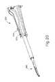
I.開腹外科手術用の第1の例示的な超音波外科用器具
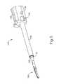
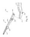
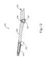
図1A~図2及び図13A~図13Cは、第1の例示的な超音波外科用器具(10)を示す。器具(10)の少なくとも一部は、以下の参考文献の教示の少なくとも一部に従って構築され、動作可能であり得る:米国特許第5,322,055号、米国特許第5,873,873号、米国特許第5,980,510号、米国特許第6,325,811号、米国特許第6,773,444号、米国特許第6,783,524号、米国特許出願公開第2006/0079874号、米国特許出願公開第2007/0191713号、米国特許出願公開第2007/0282333号、米国特許出願公開第2008/0200940号、米国特許第8,623,027号、米国特許第9,023,071号、米国特許第8,461,744号、米国特許第9,381,058号、米国特許出願公開第2012/0116265号、米国特許第9,393,037号、米国特許第9,095,367号、米国特許出願第61/410,603号、及び/又は米国特許出願公開第2015/0080924号。前述の特許、特許公開、及び特許出願のそれぞれの開示は、参照により本明細書に組み込まれる。加えて又は代わりに、器具(10)の少なくとも一部は、その開示が参照により本明細書に組み込まれる、米国特許出願公開第2017/0105755号、名称「Surgical Instrument with Dual Mode End Effector and Compound Lever with Detents」(2017年4月20日公開)、その開示が参照により本明細書に組み込まれる、米国特許出願第62/363,411号、名称「Surgical Instrument with Dual Mode End Effector」(2016年7月18日出願)の少なくとも一部の教示に従って構成され、動作可能であり得る。I. First Exemplary Ultrasound Surgical Instrument for Open Surgery FIGS. 1A-2 and 13A-13C show a first exemplary ultrasonic surgical instrument (10). At least a portion of the instrument (10) may be constructed and operational according to at least some of the teachings of the following references: US Pat. No. 5,322,055, US Pat. No. 5,873,873, US Patent No. 5,980,510, US Patent No. 6,325,811, US Patent No. 6,773,444, US Patent No. 6,783,524, US Patent Application Publication No. 2006/0079874, US Patent Application Publication No. 2007/01/91713, US Patent Application Publication No. 2007/0282333, US Patent Application Publication No. 2008/0200940, US Patent No. 8,623,027, US Patent No. 9,023,071, US Patent No. 8,461,744, US Patent No. 9,381,058, US Patent Application Publication No. 2012/0116265, US Patent No. 9,393,037, US Patent No. 9,095,367, US Patent Application No. 61 / 410,603 and / or US Patent Application Publication No. 2015/0080924. The disclosures of the aforementioned patents, patent publications, and patent applications are incorporated herein by reference. In addition or instead, at least a portion of the instrument (10), the disclosure of which is incorporated herein by reference, US Patent Application Publication No. 2017/0105755, entitled "Surgical Instrument with Dual Model End Effector and Compound Lever". "With Detents" (published April 20, 2017), US Patent Application No. 62 / 363,411, entitled "Surgical Instrument with Dual Mode End Effector" (7/2016), the disclosure of which is incorporated herein by reference. It may be constructed and operational according to at least some of the teachings of (filed 18th May).
以下で更に詳細に説明するように、器具(10)は、実質的に同時に、組織を切断し、かつ組織(例えば、血管など)を封止又は接合するように動作可能である。また、器具(10)が、HARMONIC ACE(登録商標)Ultrasonic Shears、HARMONIC WAVE(登録商標)Ultrasonic Shears、HARMONIC FOCUS(登録商標)Ultrasonic Shears、及び/又はHARMONIC SYNERGY(登録商標)Ultrasonic Bladesと様々な構造的及び機能的な類似性を有し得ることを理解されたい。更に、器具(10)は、本明細書で引用され、参照により本明細書に組み込まれるその他の参考文献のうちのいずれかにおいて教示されるデバイスと、様々な構造的及び機能的類似性を有し得る。 As described in more detail below, the instrument (10) can operate substantially simultaneously to cut tissue and seal or join tissue (eg, blood vessels, etc.). In addition, the device (10) is Harmonic ACE (registered trademark) Ultrasonic Shears, HARMONIC WAVE (registered trademark) Ultrasonic Shears, HARMONIC FOCUS (registered trademark) Ultrasonic Blades (registered trademark) Ultrasonic Shears (registered trademark) Ultrasonic Blade (registered trademark) Ultrasonic Shears (registered trademark) Ultrasonic Shears (registered trademark) Ultrasonic Shears (registered trademark) It should be understood that they can have physical and functional similarities. In addition, instrument (10) has various structural and functional similarities to the devices cited herein and taught in any of the other references incorporated herein by reference. Can be.
本実施例における器具(10)は、第1のモジュール式アセンブリ(100)と、第2のモジュール式アセンブリ(200)と、連結部材(300)と、を含む。以下に更に詳細に記載するように、連結部材(300)は、器具(10)をエンドエフェクタ(12)と共に形成するために、第1のモジュール式アセンブリ(100)を第2のモジュール式アセンブリ(200)に選択的に取り付けてもよい。図1A及び図1Bで最もよく分かるように、エンドエフェクタ(12)は、超音波ブレード(150)と、クランプパッドアセンブリ(220)のクランプパッド(222)と、を備える。 The instrument (10) in this embodiment includes a first modular assembly (100), a second modular assembly (200), and a connecting member (300). As will be described in more detail below, the connecting member (300) will form a first modular assembly (100) with a second modular assembly (100) in order to form the instrument (10) with the end effector (12). It may be selectively attached to 200). As best seen in FIGS. 1A and 1B, the end effector (12) comprises an ultrasonic blade (150) and a clamp pad (222) of the clamp pad assembly (220).
加えて、以下に更に詳細に記載するように、第2のモジュール式アセンブリ(200)の選択された部分は、互いに適切に取り付けられると、エンドエフェクタ(12)を開いた構成(図1A及び図16A)から閉じた構成(図1B及び図16B)に作動させるために、第1のモジュール式アセンブリ(100)に対して作動し得る。第2のモジュール式アセンブリ(200)を第1のモジュール式アセンブリ(100)に選択的に取り付け、かつ取り外す能力は、モジュール式アセンブリ(100、200)のいずれかの再利用性の更なる利益を提供し得る。例えば、異なる種類の第1のモジュール式アセンブリ(100)を第2のモジュール式アセンブリ(200)と共に使用して、異なる種類の外科用器具を提供してもよい。同様に、異なる種類の第2のモジュール式アセンブリ(200)を第1のモジュール式アセンブリ(100)と共に使用して、異なる種類の外科用器具を提供してもよい。加えて、第2のモジュール式アセンブリ(200)の移動構成要素は、第2のモジュール式アセンブリ(200)の静的構成要素内に収容されてもよく、これは追加の利点を提供することができ、そのうちの一部が以下に記載されるが、他の構成要素も本明細書の教示に照らして当業者には明らかとなるであろう。 In addition, as described in more detail below, the selected portions of the second modular assembly (200) will open the end effector (12) when properly attached to each other (FIGS. 1A and FIG. 16A) may be actuated against the first modular assembly (100) to actuate into a closed configuration (FIGS. 1B and 16B). The ability to selectively attach and remove the second modular assembly (200) to the first modular assembly (100) further benefits the reusability of any of the modular assemblies (100, 200). Can be provided. For example, different types of first modular assembly (100) may be used in conjunction with second modular assembly (200) to provide different types of surgical instruments. Similarly, different types of second modular assembly (200) may be used in conjunction with first modular assembly (100) to provide different types of surgical instruments. In addition, the moving component of the second modular assembly (200) may be housed within the static component of the second modular assembly (200), which may provide additional advantages. Yes, some of which are described below, but other components will also be apparent to those of skill in the art in the light of the teachings herein.
第1のモジュール式アセンブリ(100)は、ハンドルアセンブリ(110)と、ハンドルアセンブリ(110)から遠位に延在するシャフトアセンブリ(130)と、シャフトアセンブリ(130)から遠位に延在する超音波ブレード(150)と、を含む。ハンドルアセンブリ(110)は、本体(112)と、指グリップリング(124)と、指グリップリング(124)の遠位にある一対のボタン(126)と、本体(112)内に収容された超音波トランスデューサアセンブリ(30)と、を含む。 The first modular assembly (100) includes a handle assembly (110), a shaft assembly (130) extending distally from the handle assembly (110), and an ultrasound extending distally from the shaft assembly (130). Includes a sonic blade (150). The handle assembly (110) is housed in a body (112), a finger grip ring (124), a pair of buttons (126) distal to the finger grip ring (124), and a super body (112). Includes a sonic transducer assembly (30).
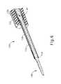
シャフトアセンブリ(130)は、本体(112)から遠位に延在する近位外部シース(132)と、近位外部シース(132)から遠位に延在するチューブ(138)と、近位外部シース(132)及びチューブ(138)の両方の中で、そこを通って延在する導波管(140)と、を含む。近位外部シース(132)は、一対の突出部(136)を含む。加えて、近位外部シース(132)は、一対の凹部(134)を画定する。以下に更に詳細に記載するように、凹部(134)は、遠位外部シース(230)の一部分と嵌合するように寸法決めされる一方、突出部(136)は、近位外部シース(132)を連結部材(300)と枢動可能に連結するように構成されている。凹部(134)と突出部(136)との両方は、第1のモジュール式アセンブリ(100)を連結部材(300)と連結するのに役立ち得る。 The shaft assembly (130) comprises a proximal external sheath (132) extending distally from the body (112), a tube (138) extending distally from the proximal external sheath (132), and a proximal external sheath. Includes a waveguide (140) extending through the sheath (132) and the tube (138). The proximal external sheath (132) includes a pair of protrusions (136). In addition, the proximal outer sheath (132) defines a pair of recesses (134). As described in more detail below, the recess (134) is sized to fit a portion of the distal external sheath (230), while the protrusion (136) is the proximal external sheath (132). ) Is configured to be pivotally connected to the connecting member (300). Both the recess (134) and the protrusion (136) can help connect the first modular assembly (100) to the connecting member (300).
近位外部シース(132)は、本体(112)に対して固定され得る一方、チューブ(138)は、近位外部シース(132)に対して固定され得る。以下に更に詳細に記載するように、導波管(140)は、トランスデューサアセンブリ(30)に取り付けられ、外部シース(132)及びチューブ(138)に近位の部分によって支持されてもよい。超音波ブレード(150)は、導波管(140)に一体的に接続されてもよく、導波管(140)から遠位に延在してもよい。以下に更に詳細に記載するように、導波管(140)は、超音波ブレード(150)とトランスデューサアセンブリ(30)との間に音響通信を提供するために、超音波トランスデューサアセンブリ(30)と接続するように動作可能である。 The proximal external sheath (132) can be secured to the body (112), while the tube (138) can be secured to the proximal external sheath (132). As described in more detail below, the waveguide (140) may be attached to the transducer assembly (30) and supported by a portion proximal to the external sheath (132) and tube (138). The ultrasonic blade (150) may be integrally connected to the waveguide (140) or may extend distally from the waveguide (140). As described in more detail below, the waveguide (140) is with the ultrasonic transducer assembly (30) to provide acoustic communication between the ultrasonic blade (150) and the transducer assembly (30). It can operate to connect.
図4を参照すると、超音波トランスデューサアセンブリ(30)が、ハンドルアセンブリ(110)の本体(112)内に収容されている。図1A~図1Bで最もよく分かるように、トランスデューサアセンブリ(30)は、プラグ(11)を介してジェネレータ(5)に連結されている。トランスデューサアセンブリ(30)はジェネレータ(5)から電力を受信し、圧電原理によりその電力を超音波振動へと変換する。ジェネレータ(5)は、電源、及びトランスデューサアセンブリ(30)による超音波振動の生成に特に適したトランスデューサアセンブリ(30)に電力プロファイルを提供するように構成された制御モジュールを含み得る。ジェネレータ(5)はまた、エンドエフェクタ(12)がRF電気外科エネルギーを組織に印加するのを可能にする電力プロファイルを提供するように構成され得る。 Referring to FIG. 4, the ultrasonic transducer assembly (30) is housed within the body (112) of the handle assembly (110). As best seen in FIGS. 1A-1B, the transducer assembly (30) is connected to the generator (5) via a plug (11). The transducer assembly (30) receives electric power from the generator (5) and converts the electric power into ultrasonic vibrations by the piezoelectric principle. The generator (5) may include a power supply and a control module configured to provide a power profile to the transducer assembly (30) that is particularly suitable for generating ultrasonic vibrations by the transducer assembly (30). The generator (5) may also be configured to provide a power profile that allows the end effector (12) to apply RF electrosurgical energy to the tissue.
あくまで一例として、ジェネレータ(5)は、Ethicon Endo-Surgery,Inc.(Cincinnati,Ohio)により販売されているGEN300を含んでもよい。加えて又は代わりに、ジェネレータ(図示せず)は、その開示が参照により本明細書に組み込まれる、米国特許第8,986,302号、名称「Surgical Generator for Ultrasonic and Electrosurgical Devices」(2015年3月24日発行)の教示の少なくとも一部に従って構築することができる。また、ジェネレータ(5)の機能性の少なくとも一部をハンドルアセンブリ(110)に組み込むことができ、またハンドルアセンブリ(110)は、電池又はその他の内蔵電源を更に含み得、その結果プラグ(11)が省略されることも理解されたい。ジェネレータ(5)がとり得る更にその他の好適な形態、並びにジェネレータ(5)が提供し得る様々な特徴及び動作性は、本明細書の教示に照らして当業者には明らかとなるであろう。 As an example, the generator (5) is described by Ethicon Endo-Surgery, Inc. GEN300 sold by (Cincinnati, Ohio) may be included. In addition or instead, the generator (not shown) is US Pat. No. 8,986,302, the name "Surgical Generator for Ultrasonic and Electrical Devices" (2015 3), the disclosure of which is incorporated herein by reference. It can be constructed according to at least a part of the teaching (issued on 24th of March). Also, at least some of the functionality of the generator (5) can be incorporated into the handle assembly (110), which may further include a battery or other built-in power supply, resulting in a plug (11). It should also be understood that is omitted. Yet other suitable embodiments that the generator (5) can take, as well as various features and operability that the generator (5) can provide, will be apparent to those of skill in the art in the light of the teachings herein.
トランスデューサアセンブリ(30)によって生成される超音波振動は、適切に連結されたときに音響導波管(140)に沿って伝達される。導波管(140)は、機械的かつ音響的にトランスデューサアセンブリ(30)に連結される。導波管(140)は、シャフトアセンブリ(130)を通って超音波ブレード(150)まで延在する。導波管(140)は、導波管(140)及び近位外部シース(132)を通って延在するピン(135)を介して、近位外部シース(132)及び/又は本体(112)に留められてもよい。ピン(135)は、導波管(140)が非起動状態にある(すなわち、超音波的に振動していない)とき、導波管(140)がシャフトアセンブリ(130)の残りの部分に対して長手方向に回転して固定されたままにするのに役立ち得る。 The ultrasonic vibrations generated by the transducer assembly (30) are transmitted along the acoustic waveguide (140) when properly coupled. The waveguide (140) is mechanically and acoustically coupled to the transducer assembly (30). The waveguide (140) extends through the shaft assembly (130) to the ultrasonic blade (150). The waveguide (140) is via a pin (135) extending through the waveguide (140) and the proximal outer sheath (132) to the proximal outer sheath (132) and / or the body (112). May be fastened to. Pins (135) are such that the waveguide (140) is relative to the rest of the shaft assembly (130) when the waveguide (140) is in the non-activated state (ie, not ultrasonically vibrating). Can help to rotate longitudinally and remain fixed.
加えて、導波管(140)は、チューブ(138)の内部と導波管(140)の外部との間に位置する封止部(142)を介して、チューブ(138)によって支持されてもよい。封止部(142)はまた、望ましくない物質及び流体が導波管(140)を収容するチューブ(138)の部分に入ることを防止し得る。ピン(135)及び封止部(142)は、導波管(140)を通して伝達される共振超音波振動に関連付けられているノードに対応する、導波管(140)の長さに沿った位置に位置する。したがって、導波管(140)とピン(135)との間の接触、及び導波管(140)と封止部(142)との間の接触は、導波管(154)を通して伝達される超音波振動に影響を及ぼし得ない。 In addition, the waveguide (140) is supported by the tube (138) via a seal (142) located between the inside of the tube (138) and the outside of the waveguide (140). May be good. The seal (142) can also prevent unwanted substances and fluids from entering the portion of the tube (138) that houses the waveguide (140). Pins (135) and seals (142) are located along the length of the waveguide (140), corresponding to the nodes associated with the resonant ultrasonic vibrations transmitted through the waveguide (140). Located in. Therefore, the contact between the waveguide (140) and the pin (135) and the contact between the waveguide (140) and the seal (142) are transmitted through the waveguide (154). Cannot affect ultrasonic vibration.
超音波ブレード(150)が起動状態にある(すなわち、超音波振動している)とき、特に組織がクランプパッド(222)と超音波ブレード(150)との間にクランプされている場合に、超音波ブレード(150)は、組織を効果的に切断及び封止するように動作可能である。導波管(140)は、導波管(140)を通して伝達される機械的振動を増幅するように構成され得ることを理解されたい。更に、導波管(140)は、長手方向の振動のゲインを導波管(140)に沿って制御するように動作可能な特徴、及び/又は導波管(140)をシステムの共振周波数に同調させる特徴部を含み得る。 Ultrasound when the ultrasonic blade (150) is in the activated state (ie, ultrasonically vibrating), especially when the tissue is clamped between the clamp pad (222) and the ultrasonic blade (150). The ultrasonic blade (150) can operate to effectively cut and seal the tissue. It should be understood that the waveguide (140) can be configured to amplify the mechanical vibrations transmitted through the waveguide (140). In addition, the waveguide (140) is capable of operating to control the gain of longitudinal vibration along the waveguide (140) and / or the waveguide (140) to the resonant frequency of the system. It may include feature parts to be tuned.
本実施例では、組織による負荷が音響アセンブリに加えられていないとき、好ましい共振周波数foに合わせて音響アセンブリを同調させるために、超音波ブレード(150)の遠位端は、導波管(140)を通して伝達される共振超音波振動に関連付けられているアンチノードに対応する位置に位置する。トランスデューサアセンブリ(30)が通電されると、超音波ブレード(150)の遠位端は、例えば、ピーク間で約10~500マイクロメートルの範囲、場合によっては、例えば、55.5kHzの所定の振動周波数foにて約20~約200マイクロメートルの範囲で長手方向に移動するように構成されている。本実施例のトランスデューサアセンブリ(30)を起動させると、これらの機械的振動が導波管(140)を通って伝達されて、超音波ブレード(150)に到達することによって、共振超音波周波数で超音波ブレード(150)の振動を提供する。したがって、組織が超音波ブレード(150)とクランプパッド(222)との間に留められると、超音波ブレード(150)の超音波振動が組織を切断するのと同時に隣接組織細胞内のタンパク質を変性させることによって、比較的少量の熱分散しか伴わない凝固効果がもたらされ得る。In this embodiment, the distal end of the ultrasonic blade (150) is a waveguide (in order to tune the acoustic assembly to the preferred resonant frequencyfo when no tissue load is applied to the acoustic assembly. It is located at the position corresponding to the antinode associated with the resonant ultrasonic vibration transmitted through 140). When the transducer assembly (30) is energized, the distal end of the ultrasonic blade (150) will have a predetermined vibration, eg, in the range of about 10-500 micrometers between peaks, and in some cases, 55.5 kHz. It is configured to move longitudinally in the range of about 20 to about 200 micrometers at a frequencyfo . When the transducer assembly (30) of this embodiment is activated, these mechanical vibrations are transmitted through the waveguide (140) and reach the ultrasonic blade (150) at the resonant ultrasonic frequency. Provides vibration of the ultrasonic blade (150). Therefore, when the tissue is fastened between the ultrasonic blade (150) and the clamp pad (222), the ultrasonic vibration of the ultrasonic blade (150) cuts the tissue and at the same time denatures the proteins in the adjacent tissue cells. This can result in a coagulation effect with only a relatively small amount of heat dispersion.
一部の変形形態では、超音波ブレード(150)及び/又はクランプパッド(222)を通して電流も提供して、組織を封止してもよい。したがって、器具(10)はまた、エンドエフェクタ(12)を介して手術部位に高周波(RF)エネルギーを提供するように構成され得ることを理解されたい。あくまでも一例として、操作者は、超音波ブレード(150)とクランプパッド(222)との間に捕捉されている組織を切断するために、ブレード(150)からの超音波エネルギーの使用に主として依存し得る。操作者は、切断された組織を封止するために、エンドエフェクタ(12)からのRFエネルギーの使用に更に依存し得る。言うまでもなく、ブレード(150)からの超音波エネルギーが、ある程度組織を封止し、そのためエンドエフェクタ(12)からのRFエネルギーが、超音波エネルギーによって既にもたらされているであろう封止を補い得ることが理解されるであろう。また、操作者が、超音波エネルギーを組織に印加することなくRFエネルギーのみを組織に印加するために、単にエンドエフェクタ(12)を使用することを望む場合があり得ることも理解されるであろう。本明細書の記載から理解されるように、器具(10)の一部の変形形態は、上記の種類の機能の全てを提供することができる。器具(10)が、超音波及びRF電気外科の動作モードの両方を提供するように構成され、動作可能であり得る様々な方法が、本明細書で引用される様々な参考文献に記載されている一方、器具(10)が超音波及びRF電気外科の両方の動作モードを提供するように構成され、動作可能であり得る他の方法が、本明細書の教示に照らして当業者には明らかとなるであろう。 In some variants, current may also be provided through the ultrasonic blade (150) and / or the clamp pad (222) to seal the tissue. Therefore, it should be understood that the instrument (10) can also be configured to provide radio frequency (RF) energy to the surgical site via the end effector (12). As an example only, the operator relies primarily on the use of ultrasonic energy from the blade (150) to cut the tissue trapped between the ultrasonic blade (150) and the clamp pad (222). obtain. The operator may further rely on the use of RF energy from the end effector (12) to seal the cut tissue. Needless to say, the ultrasonic energy from the blade (150) seals the tissue to some extent, so the RF energy from the end effector (12) supplements the encapsulation that would have already been provided by the ultrasonic energy. It will be understood to get. It is also understood that the operator may wish to simply use the end effector (12) to apply only RF energy to the tissue without applying ultrasonic energy to the tissue. Let's go. As will be appreciated from the description herein, some variants of the device (10) can provide all of the above types of functions. Various methods in which the instrument (10) is configured to provide both ultrasonic and RF electrosurgery operating modes and may be operational are described in the various references cited herein. Meanwhile, other methods in which the instrument (10) is configured to provide both ultrasonic and RF electrosurgical operating modes and may be operational are apparent to those of skill in the art in the light of the teachings herein. Will be.
操作者は、ボタン(126)を起動させてトランスデューサアセンブリ(30)を選択的に起動させ、それによって超音波ブレード(150)を起動させ得る。本実施例では、2つのボタン(126)が提供されている。一部の変形形態では、1つのボタン(126)が、超音波ブレード(150)を第1の電力プロファイル(例えば、第1の周波数及び/又は第1の振幅)で起動させるために提供され、別のボタン(126)が、超音波ブレード(150)を第2の電力プロファイル(例えば、第2の周波数及び/又は第2の振幅)で起動させるために提供されている。一部のその他の変形形態では、1つのボタン(126)が超音波ブレード(150)を超音波エネルギーで起動させるために提供され、もう1つのボタン(126)が、エンドエフェクタ(12)をRFエネルギーで起動させるために提供されている。一部のその他の変形形態では、1つのボタン(126)は、超音波ブレード(150)を超音波エネルギーで起動させると同時に、エンドエフェクタ(12)をRFエネルギーで起動させるように動作可能である一方、他方のボタン(126)は、超音波ブレード(150)を超音波エネルギーで起動させるように動作可能であるだけである。一部のその他の変形形態では、少なくとも1つのボタン(126)は、超音波ブレード(150)を超音波エネルギーで最初に起動させ、次いで、ボタン(126)を起動させたまま、1つ以上のその他の条件(例えば、時間、測定されたインピーダンスなど)に基づいて、最終的にエンドエフェクタ(12)をRFエネルギーで起動させる一方、やはり超音波ブレード(150)を超音波エネルギーで起動させるように動作可能である。一部のその他の変形形態では、少なくとも1つのボタン(126)は、超音波ブレード(150)を超音波エネルギーで最初に起動させ、次いで、ボタン(126)を起動させたまま、1つ以上のその他の状態(例えば、時間、測定されたインピーダンスなど)に基づいて、最終的にエンドエフェクタ(12)をRFエネルギーで起動させる一方、超音波ブレード(150)の起動を超音波エネルギーで停止させるように動作可能である。一部のその他の変形形態では、少なくとも1つのボタン(126)は、エンドエフェクタ(12)をRFエネルギーで最初に起動させ、次いで、ボタン(126)を起動させたまま、1つ以上のその他の条件(例えば、時間、測定されたインピーダンスなど)に基づいて、最終的に超音波ブレード(150)を超音波エネルギーで起動させる一方、エンドエフェクタ(12)の起動をRFエネルギーで停止させるように動作可能である。 The operator may activate the button (126) to selectively activate the transducer assembly (30), thereby activating the ultrasonic blade (150). In this embodiment, two buttons (126) are provided. In some variants, one button (126) is provided to activate the ultrasonic blade (150) with a first power profile (eg, first frequency and / or first amplitude). Another button (126) is provided to activate the ultrasonic blade (150) with a second power profile (eg, a second frequency and / or a second amplitude). In some other variants, one button (126) is provided to activate the ultrasonic blade (150) with ultrasonic energy, and another button (126) RFs the end effector (12). It is provided to be activated by energy. In some other variants, one button (126) can operate to activate the ultrasonic blade (150) with ultrasonic energy while at the same time activating the end effector (12) with RF energy. The other button (126), on the other hand, is only operable to activate the ultrasonic blade (150) with ultrasonic energy. In some other variants, at least one button (126) activates the ultrasonic blade (150) first with ultrasonic energy and then one or more with the button (126) activated. Based on other conditions (eg, time, measured impedance, etc.), the end effector (12) is finally activated with RF energy, while the ultrasonic blade (150) is also activated with ultrasonic energy. It is operational. In some other variants, at least one button (126) activates the ultrasonic blade (150) first with ultrasonic energy and then one or more with the button (126) activated. Based on other conditions (eg, time, measured impedance, etc.), the end effector (12) is finally activated with RF energy, while the ultrasonic blade (150) is stopped with ultrasonic energy. It is possible to operate. In some other variants, the at least one button (126) first activates the end effector (12) with RF energy and then one or more other variants with the button (126) still activated. Based on the conditions (eg time, measured impedance, etc.), the ultrasonic blade (150) is finally started with ultrasonic energy, while the end effector (12) is stopped with RF energy. It is possible.
任意の他の好適な数のボタン並びに/あるいは選択可能な電力レベル及び/又は電力の様式が提供され得ることを理解されたい。例えば、トランスデューサアセンブリ(30)を選択的に起動させるために、フットペダルが提供され得る。 It should be appreciated that any other suitable number of buttons and / or selectable power levels and / or modes of power may be provided. For example, a foot pedal may be provided to selectively activate the transducer assembly (30).
本実施例のボタン(126)は、操作者が片手で器具(10)を容易にかつ完全に操作できるように位置決めされている。例えば、第1及び第2のモジュール式アセンブリ(100、200)が連結されると、操作者は、親指グリップリング(214)内に親指を位置決めし、指グリップリング(124)内に薬指を位置決めし、本体(112)の周りに中指を位置決めし、人差し指を使用してボタン(126)を操作することができる。当然のことながら、任意のその他の好適な技術を使用して、器具(10)を把持及び操作してもよく、ボタン(126)は、任意のその他の好適な位置に位置してもよい。 The button (126) of this embodiment is positioned so that the operator can easily and completely operate the instrument (10) with one hand. For example, when the first and second modular assemblies (100, 200) are coupled, the operator positions the thumb within the thumb grip ring (214) and the ring finger within the finger grip ring (124). The middle finger can be positioned around the body (112) and the index finger can be used to operate the button (126). Of course, any other suitable technique may be used to grip and operate the instrument (10) and the button (126) may be located in any other suitable position.
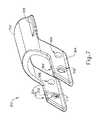
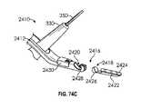
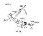
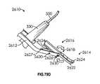
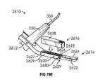
上述し、また以下に記載するように、連結部材(300)は、第1のモジュール式アセンブリ(100)を第2のモジュール式アセンブリ(200)と選択的に連結するように構成されている。図7で最もよく分かるように、連結部材(300)は、本体(302)と、本体(302)から延在する一対の弾性アーム(304)と、本体(302)から延在する一対のグリップ(305)と、を備える。弾性アーム(304)は各々、対応する枢動ボア(306)及びロッキングアセンブリ(308)を画定する。弾性アーム(304)は、近位外部シース(132)を受容し、対応する突出部(136)を有する枢動ボア(306)をスナップ嵌めするために、互いに離間配置されている。したがって、図13B~図13C及び14B~図14Cに示されるように、連結部材(300)は、枢動ボア(306)及び突出部(136)を介して、近位外部シース(132)と枢動可能に接続するように構成されている。本実施例では、連結部材(300)と近位外部シース(132)とはスナップ嵌めによって枢動可能に連結されているが、本明細書の教示に照らして当業者には明らかとなるように、任意の他のタイプの好適な接続が使用され得る。例えば、突出部(136)は、連結部材(300)の枢動ボア(306)と枢動可能に連結するために、近位外部シース(132)に対して延在可能であってもよい。グリップ(305)は、操作者が外部シース(132)に対してグリップ(305)を介して連結部材(300)を容易に回転させることができるように、本体(302)上に位置決めされてもよい。 As described above and below, the connecting member (300) is configured to selectively connect the first modular assembly (100) to the second modular assembly (200). As can be best seen in FIG. 7, the connecting member (300) has a main body (302), a pair of elastic arms (304) extending from the main body (302), and a pair of grips extending from the main body (302). (305) and. Elastic arms (304) define the corresponding pivot bore (306) and locking assembly (308), respectively. The elastic arms (304) are spaced apart from each other to receive the proximal outer sheath (132) and snap fit the pivot bore (306) with the corresponding protrusion (136). Thus, as shown in FIGS. 13B-13C and 14B-14C, the connecting member (300) is pivotally with the proximal external sheath (132) via the pivot bore (306) and protrusion (136). It is configured to connect movably. In this embodiment, the connecting member (300) and the proximal external sheath (132) are pivotally connected by snap fitting, as will be apparent to those skilled in the art in the light of the teachings herein. , Any other type of suitable connection may be used. For example, the protrusion (136) may be extendable with respect to the proximal outer sheath (132) to pivotally connect with the pivot bore (306) of the connecting member (300). The grip (305) may be positioned on the body (302) so that the operator can easily rotate the connecting member (300) with respect to the external sheath (132) via the grip (305). good.
各ロッキングアセンブリ(308)は、互いに面している内部接触壁(310)と、連結凹部(312)と、を含む。以下に更に詳細に記載するように、ロッキングアセンブリ(308)は、第2のモジュール式アセンブリ(200)の一部分と選択的に連結するために、枢動ボア(306)及び突出部(136)の周りで回転するように構成されている。 Each locking assembly (308) includes an internal contact wall (310) facing each other and a connecting recess (312). As described in more detail below, the locking assembly (308) has a pivot bore (306) and a protrusion (136) to selectively connect with a portion of the second modular assembly (200). It is configured to rotate around.
本実施例の連結部材(300)は、第1のモジュール式アセンブリ(100)を第2のモジュール式アセンブリ(200)と接続するために使用されるが、連結部材(300)は、本明細書の教示に照らして当業者には明らかとなるであろう、任意の好適なタイプのモジュール式アセンブリに組み込まれ得ることを理解されたい。例えば、連結アセンブリ(300)は、異なるモジュール式クランプアームアセンブリを第1のモジュール式アセンブリ(100)と連結するように改変されてもよく、異なるモジュール式クランプアームアセンブリは、その開示が参照により本明細書に組み込まれる、米国特許出願公開第2017/0105788号、名称「Surgical Instrument with Dual Mode End Effector and Modular Clamp Arm Assembly」(2017年4月20日公開)に教示されるものなどのクランプアームアセンブリを含む。したがって、第1のモジュール式アセンブリ(100)と連結され得る1つのモジュール式クランプアームアセンブリは、超音波ブレード(150)の一方の側でクランプアームの枢動運動を提供し得る一方、第1のモジュール式アセンブリ(100)と連結され得る他方のモジュール式クランプアームアセンブリは、超音波ブレード(150)の他方の側でクランプアームの枢動運動を提供し得る。異なる種類の第2のモジュール式アセンブリ(200)を提供するために使用され得る他の好適な種類のクランプアームアセンブリが、本明細書の教示に照らして当業者には明らかとなるであろう。 The connecting member (300) of this embodiment is used to connect the first modular assembly (100) to the second modular assembly (200), while the connecting member (300) is described herein. It should be understood that it can be incorporated into any suitable type of modular assembly, which will be apparent to those of skill in the art in the light of the teachings of. For example, the coupling assembly (300) may be modified to connect a different modular clamp arm assembly with a first modular assembly (100), the different modular clamp arm assemblies being disclosed by reference in the present. Clamp assembly as taught in US Patent Application Publication No. 2017/0105788, entitled "Surgical Instrument with Dual Model End Effector and Modular Clamp Arm Assembly" (published April 20, 2017), which is incorporated herein. including. Thus, one modular clamp arm assembly that can be coupled to the first modular assembly (100) can provide pivotal movement of the clamp arm on one side of the ultrasonic blade (150), while the first. The other modular clamp arm assembly, which may be coupled to the modular assembly (100), may provide pivotal motion of the clamp arm on the other side of the ultrasonic blade (150). Other suitable types of clamp arm assemblies that can be used to provide a different type of second modular assembly (200) will be apparent to those of skill in the art in the light of the teachings herein.
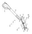
第2のモジュール式アセンブリ(200)は、クランプアームアセンブリ(210)と、クランプパッドアセンブリ(220)と、遠位外部シース(230)と、を含む。以下に更に詳細に記載するように、遠位外部シース(230)は、第1のモジュール式アセンブリ(100)を第2のモジュール式アセンブリ(200)と選択的に連結するために、連結部材(300)と近位外部シース(132)との両方と連結するように構成されている。言い換えると、適切に連結されると、近位外部シース(132)及び遠位外部シース(230)は、互いに対して固定され得る。以下に更に詳細に記載するように、クランプアームアセンブリ(210)とクランプパッドアセンブリ(220)とは両方とも、遠位外部シース(230)と枢動可能に連結されている。加えて、クランプアームアセンブリ(210)及びクランプパッドアセンブリ(220)は、遠位外部シース(230)に対する1方のアセンブリ(210、220)の回転が、遠位外部シース(230)に対する他方のアセンブリ(210、220)の回転を引き起こすように、互いに噛み合うように寸法決めされている。換言すれば、クランプアームアセンブリ(210)及びクランプパッドアセンブリ(220)は、遠位外部シース(230)に対して互いに回転することができる。 The second modular assembly (200) includes a clamp arm assembly (210), a clamp pad assembly (220), and a distal external sheath (230). As described in more detail below, the distal external sheath (230) is a connecting member (20) for selectively connecting the first modular assembly (100) to the second modular assembly (200). It is configured to connect with both the 300) and the proximal external sheath (132). In other words, when properly coupled, the proximal external sheath (132) and the distal external sheath (230) can be secured to each other. As described in more detail below, both the clamp arm assembly (210) and the clamp pad assembly (220) are pivotally coupled to the distal external sheath (230). In addition, the clamp arm assembly (210) and clamp pad assembly (220) are such that the rotation of one assembly (210, 220) with respect to the distal external sheath (230) is the rotation of the other assembly with respect to the distal external sheath (230). It is sized to mesh with each other so as to cause rotation of (210, 220). In other words, the clamp arm assembly (210) and clamp pad assembly (220) can rotate with respect to the distal external sheath (230).
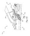
遠位外部シース(230)は、遠位面(235)から延在し、一対の近位に呈される突起(234)で終端する、U字形本体(232)を含む。近位に呈される突起(234)は各々、U字形本体(232)から離れる方向に延在する横方向突出部(238)を含む。U字形本体(232)は、長手方向経路(236)及び複数のボア(240)を画定する。U字形本体(232)及び長手方向経路(236)は、チューブ(138)を受容し、クランプアームアセンブリ(210)及びクランプパッドアセンブリ(220)の一部分を回転可能に収容するように寸法決めされている。具体的には、図13A~図13Bで最もよく分かるように、U字形本体(232)は、チューブ(138)がクランプアームアセンブリ(210)及びクランプパッドアセンブリ(220)の下に載るように、超音波ブレード(150)及びチューブ(138)の上に挿入されてもよい。チューブ(138)は、クランプアームアセンブリ(210)及びクランプパッドアセンブリ(220)が導波管(140)の隣接する部分に接触しないように、導波管(140)を保護し得る。 The distal external sheath (230) includes a U-shaped body (232) that extends from the distal surface (235) and terminates with a pair of proximally presented protrusions (234). Each proximally presented protrusion (234) includes a lateral protrusion (238) extending away from the U-shaped body (232). The U-shaped body (232) defines a longitudinal path (236) and a plurality of bores (240). The U-shaped body (232) and longitudinal path (236) are sized to receive the tube (138) and rotatably accommodate a portion of the clamp arm assembly (210) and clamp pad assembly (220). There is. Specifically, as best seen in FIGS. 13A-13B, the U-shaped body (232) is such that the tube (138) rests under the clamp arm assembly (210) and clamp pad assembly (220). It may be inserted over an ultrasonic blade (150) and a tube (138). The tube (138) may protect the waveguide (140) from contacting adjacent portions of the waveguide (140) with the clamp arm assembly (210) and the clamp pad assembly (220).
図13A~図13B及び図14A~図14Bに示されるように、近位に呈される突起(234)は、近位外部シース(132)によって画定される凹部(134)内に挿入されるように構成されている。近位に呈される突起(234)が凹部(134)内に挿入されたときに、遠位外部シース(230)は、チューブ(138)によって画定される長手方向軸の周りで近位外部シース(132)に対して回転しなくてもよい。したがって、近位に呈される突起(234)は、遠位外部シース(230)を近位外部シース(132)に対して回転的に固定するために、凹部(134)と嵌合し得る。 As shown in FIGS. 13A-13B and 14A-14B, the proximally presented protrusion (234) is to be inserted into the recess (134) defined by the proximal external sheath (132). It is configured in. When the proximally presented protrusion (234) is inserted into the recess (134), the distal external sheath (230) is located around the longitudinal axis defined by the tube (138). It does not have to rotate with respect to (132). Thus, the proximally presented protrusion (234) may fit into the recess (134) in order to rotationally secure the distal external sheath (230) to the proximal external sheath (132).
図13B~図13C、図14B~図14D、及び図15A~図15Cに示されるように、一旦遠位外部シース(230)が近位外部シース(132)に対して回転的に固定されると、操作者は、ロッキングアセンブリ(308)が横方向突出部(238)とスナップ嵌めするように、連結部材(300)を回転させ得る。具体的には、操作者は、横方向突出部(238)が弾性アーム(304)の接触壁(310)に対してカム作用するように、連結部材(300)を突出部(136)の周りで回転させてもよい。結果として、図15Bで最もよく分かるように、接触壁(310)と横方向突出部(238)との間の接触は、弾性アーム(304)を外向きに、近位に呈される突起(234)から離れる方向に撓ませる。操作者は、図13C、図14C、及び図15Cに示されるように、横方向突出部(238)が接触壁(310)に当接しなくなるように、連結部材(300)を突出部(136)の周りで更に回転させてもよい。弾性アーム(304)の弾性的性質は、横方向突出部(238)がロッキングアセンブリ(308)の連結凹部(312)内に載るように、弾性アーム(304)が弛緩位置に戻ることを可能にする。連結部材(300)のロッキングアセンブリ(308)が完全に取り付けられると、図13C、図14D、及び図15Cに示されるように、遠位外部シース(230)は、近位外部シース(132)に対して長手方向に固定され、それによって第1のモジュール式アセンブリ(100)を第2のモジュール式アセンブリ(200)と連結する。 Once the distal external sheath (230) is rotationally fixed to the proximal external sheath (132), as shown in FIGS. 13B-13C, 14B-14D, and 15A-15C. The operator may rotate the connecting member (300) so that the locking assembly (308) snaps into the lateral protrusion (238). Specifically, the operator moves the connecting member (300) around the protrusion (136) so that the lateral protrusion (238) cams against the contact wall (310) of the elastic arm (304). You may rotate it with. As a result, as best seen in FIG. 15B, the contact between the contact wall (310) and the lateral protrusion (238) is a protrusion (proximal) that is presented outward and proximal to the elastic arm (304). Bend in the direction away from 234). As shown in FIGS. 13C, 14C, and 15C, the operator attaches the connecting member (300) to the protrusion (136) so that the lateral protrusion (238) does not abut on the contact wall (310). You may rotate it further around. The elastic properties of the elastic arm (304) allow the elastic arm (304) to return to its relaxed position so that the lateral protrusion (238) rests within the connecting recess (312) of the locking assembly (308). do. When the locking assembly (308) of the connecting member (300) is fully attached, the distal external sheath (230) is attached to the proximal external sheath (132), as shown in FIGS. 13C, 14D, and 15C. In contrast, it is fixed longitudinally, thereby connecting the first modular assembly (100) to the second modular assembly (200).
操作者が第1のモジュール式アセンブリ(100)を第2のモジュール式アセンブリ(200)から分離することを望む場合、操作者は、弾性アーム(304)を撓ませて、連結凹部(312)から横方向突出部(238)を飛び出させるために、グリップ(305)を握って、連結部材(300)を突出部(136)の周りで反対方向に回転させてもよい。 If the operator wishes to separate the first modular assembly (100) from the second modular assembly (200), the operator flexes the elastic arm (304) from the connecting recess (312). In order to pop out the lateral protrusion (238), the grip (305) may be gripped and the connecting member (300) may be rotated in the opposite direction around the protrusion (136).
上述したように、クランプアームアセンブリ(210)とクランプパッドアセンブリ(220)とは両方とも、遠位外部シース(230)に対する1方のアセンブリ(210、220)の回転が、遠位外部シース(230)に対する他方のアセンブリ(210、220)の回転を引き起こすように、遠位外部シース(230)に枢動可能に連結されている。 As mentioned above, in both the clamp arm assembly (210) and the clamp pad assembly (220), the rotation of one assembly (210, 220) with respect to the distal external sheath (230) is the rotation of the distal external sheath (230). ) Is pivotally coupled to the distal external sheath (230) to cause rotation of the other assembly (210, 220).
クランプアームアセンブリ(210)は、細長いアーム(212)と、親指グリップリング(214)と、カム突出部(216)と、枢動連結具(218)と、を含む。親指グリップリング(214)及び細長いアーム(212)は一緒に、本体(112)及び指グリップリング(124)と組み合わせてはさみグリップ型の構成を提供する。枢動連結具(218)は、ピン(202)を介してクランプアームアセンブリ(210)を遠位外部シース(230)に枢動可能に連結する。以下に更に詳細に記載するように、カム突出部(216)は、クランプアームアセンブリ(210)の回転に応じて、クランプパッドアセンブリ(220)を回転させるために、クランプパッドアセンブリ(220)と相互作用する。 The clamp arm assembly (210) includes an elongated arm (212), a thumb grip ring (214), a cam protrusion (216), and a pivotal connector (218). The thumb grip ring (214) and the elongated arm (212) together, in combination with the body (112) and the finger grip ring (124), provide a scissors grip type configuration. The pivotal connector (218) pivotally connects the clamp arm assembly (210) to the distal external sheath (230) via a pin (202). As described in more detail below, the cam overhangs (216) interact with the clamp pad assembly (220) to rotate the clamp pad assembly (220) in response to the rotation of the clamp arm assembly (210). It works.
クランプパッドアセンブリ(220)は、超音波ブレード(150)に面するクランプパッド(222)と、超音波ブレード(150)に隣接し、かつクランプパッド(222)に近位に位置する一対の組織止め部(223)と、カム凹部(226)とばね凹部(221)との両方を画定するアーム(224)と、枢動連結具(228)と、ばね凹部(221)内に収容された板ばね(225)と、を含む。一部の変形形態では、クランプパッドアセンブリ(220)は、組織にRF電気外科エネルギーを印加するように動作可能な、1つ以上の電極を更に含む。本明細書における様々な参考文献は、クランプパッドアセンブリがRF電気外科エネルギーを組織に印加するように動作可能である1つ以上の電極を組み込むことができる方法の実施例を提供する一方、クランプパッドアセンブリ(220)がRF電気外科エネルギーを組織に印加するように動作可能である1つ以上の電極を組み込むことができる方法の他の実施例が、本明細書の教示に照らして当業者には明らかとなるであろう。 The clamp pad assembly (220) consists of a clamp pad (222) facing the ultrasonic blade (150) and a pair of tissue stops adjacent to the ultrasonic blade (150) and located proximal to the clamp pad (222). A leaf spring housed in a portion (223), an arm (224) defining both a cam recess (226) and a spring recess (221), a pivot coupling (228), and a spring recess (221). (225) and. In some variants, the clamp pad assembly (220) further comprises one or more electrodes that can be operated to apply RF electrosurgical energy to the tissue. Various references herein provide examples of how the clamp pad assembly can incorporate one or more electrodes capable of operating to apply RF electrosurgical energy to the tissue, while the clamp pad. Other embodiments of the method in which the assembly (220) can incorporate one or more electrodes capable of operating to apply RF electrosurgical energy to tissue are available to those of skill in the art in the light of the teachings herein. It will be clear.
この実施例では、組織止め部(223)は、エンドエフェクタ(12)が閉じた位置にあるとき、長手方向に遠位面(235)と整列する。組織止め部(223)及び遠位面(235)は、ブレード(150)からの超音波エネルギーが、組織を適切に切断又は封止しない場合があり得る、エンドエフェクタ(12)内の近位位置に、組織が意図せず到達してしまうのを一貫してかつ単純に防止するために協働し得る。このような防止の提供において、組織止め部(223)は、操作者が、組織が不必要にエンドエフェクタ(12)内の近位位置に達したかどうかを判定するために、エンドエフェクタ(12)の近位領域を可視化する必要性を排除することができる。 In this embodiment, the tissue stop (223) aligns longitudinally with the distal surface (235) when the end effector (12) is in the closed position. The tissue stop (223) and distal surface (235) are proximal positions within the end effector (12) where ultrasonic energy from the blade (150) may not properly cut or seal the tissue. In addition, organizations can work together to consistently and simply prevent unintentional arrivals. In providing such protection, the tissue stop (223) is an end effector (12) for the operator to determine if the tissue has unnecessarily reached a proximal position within the end effector (12). ) Can be eliminated from the need to visualize the proximal region.
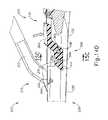
カム突出部(216)は、カム凹部(226)にも接触しながら、カム凹部(226)内で回転するように寸法決めされている。カム突出部(216)及びカム凹部(226)は、遠位外部シース(230)内に位置決めされ、そのため両方は枢動連結具(218、228)の間に位置する一方、クランプアームアセンブリ(210)及びクランプパッドアセンブリ(220)は、遠位外部シース(230)に枢動可能に連結されている。したがって、図1A~図1B及び図16A~図16Bに示されるように、操作者が、細長いアーム(212)を枢動連結具(218)の周りで遠位外部シース(230)に向けて回転させると、カム突出部(216)は、遠位外部シース(230)から離れる方向に枢動連結具(218)の周りで回転する。カム突出部(216)は、カム凹部(226)内に収容されているので、枢動連結具(218)の周りのカム突出部(216)の上方への移動は、カム凹部(226)の枢動連結具(228)の周りの上方への移動を引き起こす。枢動連結具(228)の周りのカム凹部(226)の上方への移動は、クランプパッド(222)が超音波ブレード(150)に向かって回転するようにアーム(224)を回転させる。したがって、クランプアームアセンブリ(210)の細長いアーム(212)をハンドルアセンブリ(110)に向けて閉じると、クランプパッド(222)は、超音波ブレード(150)に向かって閉じる。それゆえ、第1のモジュール式アセンブリ(100)と第2のモジュール式アセンブリ(200)とが接続されると、操作者は、親指グリップリング(214)を本体(112)に向けて握り締め、それによって組織をクランプパッドアセンブリ(220)と超音波ブレード(150)との間にクランプして、組織を超音波ブレード(150)に対して圧縮し得るということを理解されたい。そのような圧縮時に超音波ブレード(150)が起動されると、クランプパッドアセンブリ(220)と超音波ブレード(150)とが協働して、圧縮された組織を切除及び/又は封止する。 The cam protrusion (216) is sized to rotate in the cam recess (226) while also in contact with the cam recess (226). The cam protrusion (216) and cam recess (226) are positioned within the distal external sheath (230) so that both are located between the pivot connectors (218, 228) while the clamp arm assembly (210). ) And the clamp pad assembly (220) are pivotally coupled to the distal external sheath (230). Thus, as shown in FIGS. 1A-1B and 16A-16B, the operator rotates the elongated arm (212) around the pivot connector (218) towards the distal external sheath (230). When allowed, the cam protrusion (216) rotates around the pivot connector (218) away from the distal external sheath (230). Since the cam protrusion (216) is housed in the cam recess (226), the upward movement of the cam protrusion (216) around the pivot connector (218) is the movement of the cam recess (226). Causes an upward movement around the pivotal connector (228). The upward movement of the cam recess (226) around the pivot connector (228) rotates the arm (224) such that the clamp pad (222) rotates towards the ultrasonic blade (150). Thus, when the elongated arm (212) of the clamp arm assembly (210) is closed towards the handle assembly (110), the clamp pad (222) closes towards the ultrasonic blade (150). Therefore, when the first modular assembly (100) and the second modular assembly (200) are connected, the operator squeezes the thumb grip ring (214) towards the body (112), which It should be appreciated that the tissue can be clamped between the clamp pad assembly (220) and the ultrasonic blade (150) and the tissue can be compressed against the ultrasonic blade (150). When the ultrasonic blade (150) is activated during such compression, the clamp pad assembly (220) and the ultrasonic blade (150) work together to excise and / or seal the compressed tissue.
上述したように、板ばね(225)は、ばね凹部(221)内に収容されている。図16A~図16Bで最もよく分かるように、エンドエフェクタ(12)の1つ以上のRF電極と電力源との間に電気的導通を提供するために、板ばね(225)の一部分がバネ凹部(221)の外に延在してチューブ(138)に対して接触するように、板ばね(225)は寸法決めされている。板ばね(225)は、クランプパッドアセンブリ(220)の運動範囲にわたって、この電気的導通を維持することを理解されたい。また、エンドエフェクタ(12)の1つ以上のRF電極と電力源との間に電気的導通を提供するために、任意の他の好適な種類の特徴部が使用され得ることも理解されたい。 As described above, the leaf spring (225) is housed in the spring recess (221). As best seen in FIGS. 16A-16B, a portion of the leaf spring (225) is a spring recess to provide electrical conduction between one or more RF electrodes of the end effector (12) and the power source. The leaf spring (225) is sized so that it extends out of (221) and contacts the tube (138). It should be appreciated that the leaf spring (225) maintains this electrical continuity over the range of motion of the clamp pad assembly (220). It should also be appreciated that any other suitable type of feature may be used to provide electrical conduction between one or more RF electrodes of the end effector (12) and the power source.
一部の変形形態では、1つ以上の弾性部材を使用して、クランプパッドアセンブリ(220)を、図1A及び図16Aに図示される開いた位置に向かって付勢する。当然ながら、本明細書の教示に照らして当業者には明らかとなるように、ねじりばねなど、任意の他の好適な種類の弾性部材が使用され得る。あるいは、クランプパッドアセンブリ(220)は、必ずしも開いた位置に向かって付勢されなくてもよい。 In some variants, one or more elastic members are used to urge the clamp pad assembly (220) towards the open position shown in FIGS. 1A and 16A. Of course, any other suitable type of elastic member, such as a torsion spring, may be used, as will be apparent to those skilled in the art in the light of the teachings herein. Alternatively, the clamp pad assembly (220) does not necessarily have to be urged towards the open position.
クランプアームアセンブリ(210)及びクランプパッドアセンブリ(220)の枢動連結具(218、228)が、遠位外部シース(230)の長手方向経路(236)内に位置することは、遠位外部シース(230)の外部と枢動可能に連結するクランプアームアセンブリ(210)及びクランプパッドアセンブリ(220)と比較して、特定の望ましい利点を提供することができる。例えば、枢動連結具(218、228)がU字形本体(232)内に収容されている状態で、クランプアームアセンブリ(210)及びクランプパッドアセンブリ(220)の回転に起因して、不注意に組織を挟む可能性が低減され得る。換言すれば、U字形本体(232)は、クランプアームアセンブリ(210)及びクランプパッドアセンブリ(220)が遠位外部シース(230)に対して回転することによって、組織を不注意に挟まれることから保護することができる。加えて、枢動連結具(218、228)が遠位外部シース(230)の長手方向経路(236)内に収容されていることに起因して、第2のモジュール式アセンブリ(200)の幅が減少され得る。また、クランプアームアセンブリ(210)及びクランプパッドアセンブリ(220)の簡略化された形状に起因して、所望の構成要素を製作するのもより容易であり得る。累積公差の低減はまた、遠位外部シース(230)の内部に枢動連結具(218、228)を格納することにとって利点となり得る。 The location of the pivot connectors (218, 228) of the clamp arm assembly (210) and clamp pad assembly (220) within the longitudinal path (236) of the distal external sheath (230) is that the distal external sheath. A particular desirable advantage can be provided as compared to the clamp arm assembly (210) and the clamp pad assembly (220) that are pivotally coupled to the outside of (230). For example, carelessly due to the rotation of the clamp arm assembly (210) and the clamp pad assembly (220) while the pivot connector (218, 228) is housed in the U-shaped body (232). The possibility of pinching the tissue can be reduced. In other words, the U-shaped body (232) inadvertently pinches tissue by rotating the clamp arm assembly (210) and clamp pad assembly (220) with respect to the distal external sheath (230). Can be protected. In addition, the width of the second modular assembly (200) due to the pivotal coupling (218, 228) being housed within the longitudinal path (236) of the distal external sheath (230). Can be reduced. Also, due to the simplified shape of the clamp arm assembly (210) and clamp pad assembly (220), it may be easier to make the desired components. Reducing the cumulative tolerance can also be beneficial for storing the pivot connector (218, 228) inside the distal external sheath (230).
器具(10)の前述の構成要素及び動作性は、あくまでも例示的なものである。本明細書の教示に照らして当業者には明らかとなるように、器具(10)は多くのその他の方法で構成され得る。あくまでも一例として、器具(10)の少なくとも一部は、その開示内容が全て参照により本明細書に組み込まれる、次の特許文献のいずれかの教示の少なくとも一部に従って構築されかつ/又は動作可能であり得る:米国特許第5,322,055号、米国特許第5,873,873号、米国特許第5,980,510号、米国特許第6,325,811号、米国特許第6,783,524号、米国特許出願公開第2006/0079874号、米国特許出願公開第2007/0191713号、米国特許出願公開第2007/0282333号、米国特許出願公開第2008/0200940号、米国特許第9,023,071号、米国特許第8,461,744号、米国特許第9,381,058号、米国特許出願公開第2012/0116265号、米国特許第9,393,037号、米国特許第9,095,367号、及び/又はその開示が参照により本明細書に組み込まれる、米国特許出願公開第2015/0080925号、名称「Alignment Features for Ultrasonic Surgical Instrument」(2015年3月19日公開)。 The above-mentioned components and operability of the instrument (10) are merely exemplary. Instrument (10) can be configured in many other ways, as will be apparent to those skilled in the art in the light of the teachings herein. As an example only, at least a portion of the instrument (10) may be constructed and / or operational in accordance with at least a portion of the teachings of any of the following patent documents, the disclosure of which is incorporated herein by reference in its entirety. Possible: US Patent No. 5,322,055, US Patent No. 5,873,873, US Patent No. 5,980,510, US Patent No. 6,325,811, US Patent No. 6,783. 524, US Patent Application Publication No. 2006/0079874, US Patent Application Publication No. 2007/01/91713, US Patent Application Publication No. 2007/0282333, US Patent Application Publication No. 2008/0200940, US Patent No. 9,023. 071, US Patent No. 8,461,744, US Patent No. 9,381,058, US Patent Application Publication No. 2012/0116265, US Patent No. 9,393,037, US Patent No. 9,095, No. 367 and / or its disclosure is incorporated herein by reference, US Patent Application Publication No. 2015/0080925, entitled "Alignment Features for Ultrasonic Surgical Instrument" (published March 19, 2015).
II.開腹外科手術用の第2の例示的な超音波外科用器具
図17~図18は、第2の例示的な超音波外科用器具(301)を示す。以下で特に記載しない限り、この実施例の器具(301)は、上述した器具(10)と全く同じように構成され、動作可能であり得る。したがって、器具(301)の特定の詳細は、以下の説明から省略され、そのような詳細は、器具(10)の説明において既に上で提供されていることが理解される。II. Second Exemplary Ultrasound Surgical Instrument for Open Surgery FIGS. 17-18 show a second exemplary ultrasonic surgical instrument (301). Unless otherwise stated below, the instrument (301) of this embodiment may be configured and operational in exactly the same manner as the device (10) described above. Therefore, it is understood that certain details of the instrument (301) are omitted from the following description and such details are already provided above in the description of the instrument (10).
本実施例の器具(301)は、ハンドルアセンブリ(311)と、クランプアームアクチュエータ(320)と、シャフトアセンブリ(330)と、クランプアームアセンブリ(400)と、を備える。この実施例のハンドルアセンブリ(311)は、上述したハンドルアセンブリ(110)と同様に構成され、動作可能であり、そのためハンドルアセンブリ(311)の詳細はここでは繰り返されない。 The instrument (301) of this embodiment includes a handle assembly (311), a clamp arm actuator (320), a shaft assembly (330), and a clamp arm assembly (400). The handle assembly (311) of this embodiment is configured and operable in the same manner as the handle assembly (110) described above, so that the details of the handle assembly (311) are not repeated here.
クランプアームアクチュエータ(320)は、シャフトアセンブリ(330)に枢動可能に連結されている。本実施例では、クランプアームアクチュエータ(320)は、シャフトアセンブリ(330)から取り外し可能ではない。本実施例のクランプアームアクチュエータ(320)は、シャフト(322)を備える。親指リング(324)は、シャフト(322)の近位端に位置決めされている。図18~図19で最もよく分かるように、一対の突起(326)は、シャフト(322)から遠位に延在する。突起(326)は、互いに横方向に離間配置され、互いに平行に延在する。図19で最もよく分かるように、各突起(326)の遠位端は、カム突出部(328)を含む。カム突出部(328)は、以下に記載するように、カム突出部(216)と同様の様式で、クランプアームアセンブリ(400)と協働するように構成されている。やはり図19で最もよく分かるように、突起(326)はまた、ピン(338)を受容するように構成された一対のピン開口部(327)を画定する。ピン(338)は、クランプアームアクチュエータ(320)とシャフトアセンブリ(330)との間の枢動可能な連結を提供する。 The clamp arm actuator (320) is pivotally coupled to the shaft assembly (330). In this embodiment, the clamp arm actuator (320) is not removable from the shaft assembly (330). The clamp arm actuator (320) of this embodiment includes a shaft (322). The thumb ring (324) is positioned at the proximal end of the shaft (322). As best seen in FIGS. 18-19, the pair of protrusions (326) extend distally from the shaft (322). The protrusions (326) are laterally spaced apart from each other and extend parallel to each other. As best seen in FIG. 19, the distal end of each protrusion (326) includes a cam protrusion (328). The cam overhang (328) is configured to work with the clamp arm assembly (400) in a manner similar to the cam overhang (216), as described below. Also, as best seen in FIG. 19, the protrusions (326) also define a pair of pin openings (327) configured to receive the pins (338). The pin (338) provides a pivotable connection between the clamp arm actuator (320) and the shaft assembly (330).
シャフトアセンブリ(330)は、ハンドルアセンブリ(311)から遠位に延在し、以下に記載される相違点を除いて、上述したシャフトアセンブリ(130)と実質的に同一である。上述した超音波ブレード(150)と同一である超音波ブレード(350)は、シャフトアセンブリ(130)の遠位端に位置決めされる。図20で最もよく分かるように、シャフトアセンブリ(330)は、ピン(338)を受容するように構成された開口部(332)を画定し、それによってクランプアームアクチュエータ(320)とシャフトアセンブリ(330)との間に枢動可能な連結を提供する。やはり図20に示されるように、シャフトアセンブリ(330)は、以下に更に詳細に記載するように、クランプアームアセンブリ(400)に係合するように構成された傾斜ラッチ突出部(334)を含む。 The shaft assembly (330) extends distally from the handle assembly (311) and is substantially identical to the shaft assembly (130) described above, except for the differences described below. The ultrasonic blade (350), which is identical to the ultrasonic blade (150) described above, is positioned at the distal end of the shaft assembly (130). As best seen in FIG. 20, the shaft assembly (330) defines an opening (332) configured to receive the pin (338), thereby the clamp arm actuator (320) and the shaft assembly (330). ) Provides a pivotable connection with. As also shown in FIG. 20, the shaft assembly (330) includes an inclined latch protrusion (334) configured to engage the clamp arm assembly (400), as described in more detail below. ..
図21~図22に示されるように、本実施例のクランプアームアセンブリ(400)は、静止本体(410)に枢動可能に連結されたクランプアーム本体(430)を部分的に包囲する一対の囲い板(402、404)を備える。各囲い板は、遠位に呈される組織止め縁部(408)を含む。静止本体(410)はまた、一対の遠位に呈される組織止め縁部(418)を含む。縁部(408、418)は、協働して、上述した組織止め部(223)及び遠位面(235)のような組織の近位位置決めを一貫して制限するように構成されている。本実施例の囲い板(404)はまた、遠位に突き出すシールド部材(406)も含む。 As shown in FIGS. 21-22, the clamp arm assembly (400) of this embodiment is a pair that partially surrounds a clamp arm body (430) pivotally coupled to a stationary body (410). It is provided with an enclosure (402, 404). Each enclosure contains a tissue stop edge (408) presented distally. The resting body (410) also includes a pair of distal tissue stop edges (418). The edges (408, 418) are configured to work together to consistently limit the proximal positioning of tissues such as the tissue stop (223) and distal surface (235) described above. The enclosure (404) of this embodiment also includes a shield member (406) that projects distally.
本実施例の静止本体(410)は、ピン開口部(411)と、近位に突き出すラッチ部材(412)と、を更に含む。ラッチ部材(412)は、ラッチ開口部(414)及び傾斜部(416)を画定する。ラッチ部材(412)は、シャフトアセンブリ(330)のラッチ突出部(334)と協働して、クランプアームアセンブリ(400)をシャフトアセンブリ(330)に選択的に留めるように構成されている。具体的には、クランプアームアセンブリ(400)が最初にシャフトアセンブリ(330)とは別個に提供される場合、操作者は、クランプアームアセンブリ(400)を共通軸線に沿ってシャフトアセンブリ(330)と整列させ、次いでブレード(350)及びシャフトアセンブリ(330)の残りの遠位部分をクランプアームアセンブリ(400)に挿入できる。傾斜部(416)は、最終的にラッチ突出部(334)と係合し、これは、ラッチ部材(412)を長手方向軸から離れる方向に偏向させるカム作用を提供するであろう。操作者がクランプアームアセンブリ(400)を通してシャフトアセンブリ(330)を挿入し続けると、ラッチ突出部(334)は、最終的にラッチ開口部(414)に到達し、その時点で、ラッチ部材(412)は、直線状の非偏向状態に弾性的に戻る。この段階では、ラッチ突出部(334)は、ラッチ開口部(414)内に配設されており、それによってクランプアームアセンブリ(400)をシャフトアセンブリ(330)に留める。操作者がシャフトアセンブリ(330)からクランプアームアセンブリ(400)を取り外すことを望む場合、操作者は、単純に傾斜面(416)を係合し、それによってラッチ部材(412)を、ラッチ部材(412)がラッチ突出部(334)を取り除くことができる偏向状態に付勢し、次いで、クランプアームアセンブリ(400)をシャフトアセンブリ(330)から引き離すことができる。クランプアームアセンブリ(400)をシャフトアセンブリ(330)に留め、シャフトアセンブリ(330)からクランプアームアセンブリ(400)を取り外すために使用され得る他の好適な構造及び技術が、本明細書の教示に照らして当業者には明らかとなるであろう。 The stationary body (410) of this embodiment further includes a pin opening (411) and a latch member (412) protruding proximally. The latch member (412) defines a latch opening (414) and an inclined portion (416). The latch member (412) is configured to work with the latch protrusion (334) of the shaft assembly (330) to selectively fasten the clamp arm assembly (400) to the shaft assembly (330). Specifically, if the clamp arm assembly (400) is initially provided separately from the shaft assembly (330), the operator may use the clamp arm assembly (400) with the shaft assembly (330) along a common axis. Alignment can then be inserted into the clamp arm assembly (400) with the remaining distal portion of the blade (350) and shaft assembly (330). The ramp (416) will eventually engage the latch protrusion (334), which will provide a cam action that deflects the latch member (412) away from the longitudinal axis. As the operator continues to insert the shaft assembly (330) through the clamp arm assembly (400), the latch protrusion (334) eventually reaches the latch opening (414), at which point the latch member (412). ) Elastically returns to a linear non-deflected state. At this stage, the latch protrusion (334) is disposed within the latch opening (414), thereby fastening the clamp arm assembly (400) to the shaft assembly (330). If the operator wishes to remove the clamp arm assembly (400) from the shaft assembly (330), the operator simply engages the inclined surface (416), thereby pulling the latch member (412) into the latch member ( 412) can urge a deflected state in which the latch protrusion (334) can be removed, and then the clamp arm assembly (400) can be pulled away from the shaft assembly (330). Other suitable structures and techniques that can be used to clamp the clamp arm assembly (400) to the shaft assembly (330) and remove the clamp arm assembly (400) from the shaft assembly (330) are in light of the teachings herein. Will be apparent to those skilled in the art.
本実施例のクランプアーム本体(430)は、クランプパッド(432)と、一対の近位突起(434)と、を備える。クランプパッド(432)は、クランプアームアセンブリ(400)がシャフトアセンブリ(330)に留められたときに、超音波ブレード(350)に対して組織を圧縮するように位置決めされ、構成される。囲い板(404)のシールド部材(406)は、クランプパッド(432)を覆うことなく、クランプアーム本体(430)の遠位端の外部の上方に延在するように構成されている。したがって、シールド部材(406)は、クランプパッド(432)が組織と直接接触することを可能にする。突起(438)は各々、それぞれの近位に呈される凹部(436)と、一対のピン開口部(438)と、を備える。ピン(440)は、ピン開口部(411、438)内に位置決めされ、それによってクランプアーム本体(430)を静止本体(410)と枢動可能に連結する。囲い板(402、404)は、囲い板(402、404)が静止本体(410)に対してクランプアーム本体(430)と共に枢動するように、クランプアーム本体(430)に固定して留められる。 The clamp arm body (430) of this embodiment includes a clamp pad (432) and a pair of proximal projections (434). The clamp pad (432) is positioned and configured to compress the tissue against the ultrasonic blade (350) when the clamp arm assembly (400) is fastened to the shaft assembly (330). The shield member (406) of the enclosure (404) is configured to extend above the outside of the distal end of the clamp arm body (430) without covering the clamp pad (432). Therefore, the shield member (406) allows the clamp pad (432) to come into direct contact with the tissue. Each protrusion (438) comprises a recess (436) presented proximal to each and a pair of pin openings (438). The pin (440) is positioned within the pin opening (411, 438), thereby pivotally connecting the clamp arm body (430) to the stationary body (410). The enclosure (402, 404) is fixed and fastened to the clamp arm body (430) so that the enclosure (402, 404) pivots with the clamp arm body (430) with respect to the rest body (410). ..
図23に示されるように、凹部(436)は、概ねU字形の構成を有する。凹部(436)は、クランプアームアクチュエータ(320)のカム突出部(328)を受容するように構成されている。換言すれば、シャフトアセンブリ(330)が上述したようにクランプアームアセンブリ(400)に挿入されるとき、ラッチ部材(412)が、ラッチ部材(412)がクランプアームアセンブリ(400)をシャフトアセンブリ(330)に留める時点に到達すると、カム突出部(328)は凹部(436)に入るであろう。操作者がクランプアームアセンブリ(400)をシャフトアセンブリ(330)から取り外すとき、クランプアームアクチュエータ(320)がシャフトアセンブリ(330)に留められたままであると、カム突出部(328)は、凹部(436)を自由に出ることができる。図17で最もよく分かるように、囲い板(402、404)は、凹部(436)とカム突出部(328)との間の境界面を覆うように構成されている。凹部(436)とカム突出部(328)との間の関係は、上述したカム突出部(216)とカム凹部(226)との間の関係と実質的に同一であることを理解されたい。したがって、凹部(436)及びカム突出部(328)は、クランプアーム本体(430)とクランプアームアクチュエータ(320)との間の枢動連結を提供する。 As shown in FIG. 23, the recess (436) has a generally U-shaped structure. The recess (436) is configured to receive the cam protrusion (328) of the clamp arm actuator (320). In other words, when the shaft assembly (330) is inserted into the clamp arm assembly (400) as described above, the latch member (412) and the latch member (412) insert the clamp arm assembly (400) into the shaft assembly (330). ) Will be reached, the cam protrusion (328) will enter the recess (436). When the operator removes the clamp arm assembly (400) from the shaft assembly (330), the cam protrusion (328) will be recessed (436) if the clamp arm actuator (320) remains fastened to the shaft assembly (330). ) Can be freely exited. As best seen in FIG. 17, the enclosure (402, 404) is configured to cover the interface between the recess (436) and the cam protrusion (328). It should be understood that the relationship between the recess (436) and the cam protrusion (328) is substantially the same as the relationship between the cam protrusion (216) and the cam recess (226) described above. Therefore, the recess (436) and the cam protrusion (328) provide a pivotal connection between the clamp arm body (430) and the clamp arm actuator (320).
上述したように、クランプアームアクチュエータ(320)は、ピン(338)を介してシャフトアセンブリ(330)と枢動可能に連結されており、クランプアーム本体(430)は、ピン(440)を介して静止本体(410)と枢動可能に連結されている一方、静止本体(410)は、シャフトアセンブリ(330)に固定して留められている。凹部(436)とカム突出部(328)との間の枢動する境界面は、ピン(338、440)の長手方向位置の間に長手方向に位置決めされる。したがって、クランプアームアクチュエータ(320)及びクランプアーム本体(430)は協働して、複合レバーアセンブリを提供することを理解されたい。操作者が親指リング(324)をハンドルアセンブリ(311)に向けて枢動させると、複合レバー動作は、クランプパッド(432)の超音波ブレード(350)に向かう対応する枢動移動を提供する。 As described above, the clamp arm actuator (320) is pivotally connected to the shaft assembly (330) via a pin (338) and the clamp arm body (430) is pivotally connected via a pin (440). While pivotally coupled to the stationary body (410), the stationary body (410) is fixed and fastened to the shaft assembly (330). The pivoting interface between the recess (436) and the cam protrusion (328) is longitudinally positioned between the longitudinal positions of the pins (338, 440). Therefore, it should be understood that the clamp arm actuator (320) and the clamp arm body (430) work together to provide a composite lever assembly. When the operator pivots the thumb ring (324) towards the handle assembly (311), the compound lever movement provides a corresponding pivot movement towards the ultrasonic blade (350) of the clamp pad (432).
本実施例では、弾性ビーム(313)は、クランプアームアクチュエータ(320)に留められ、シャフトアセンブリ(330)に対して摺動可能に支えられ、そのため弾性ビーム(313)は、クランプアームアクチュエータ(320)をハンドルアセンブリ(311)から離れるように弾性的に付勢する。したがって、操作者が親指リング(324)上のグリップを弛緩させると、弾性ビーム(313)は、親指リング(324)をハンドルアセンブリ(311)から離れるように付勢し、それによってクランプパッド(432)を超音波ブレード(350)から離れるように付勢する。当然ながら、任意の他の好適な構成要素及び配置を使用して、クランプアームアクチュエータ(320)に弾性付勢を提供してもよい。あるいは、そのような弾性付勢は、単純に省かれていてもよい。 In this embodiment, the elastic beam (313) is fastened to the clamp arm actuator (320) and slidably supported relative to the shaft assembly (330) so that the elastic beam (313) is the clamp arm actuator (320). ) Elastically urges away from the handle assembly (311). Thus, when the operator relaxes the grip on the thumb ring (324), the elastic beam (313) urges the thumb ring (324) away from the handle assembly (311), thereby the clamp pad (432). ) Is urged away from the ultrasonic blade (350). Of course, any other suitable component and arrangement may be used to provide elastic urging to the clamp arm actuator (320). Alternatively, such elastic urging may simply be omitted.
III.代替の例示的な超音波外科用器具及び様々な交換可能なエンドエフェクタ特徴部
上述した外科用器具(10、301)は、それぞれのモジュール式アセンブリ及び他の取り外し可能に接続された特徴部に関連付けられた接続部を含む、様々な連結機構を有する。そのような連結機構は、外科手術の前、最中、又は後の多くの状況において有用であり得るが、一実施例では、外科用器具(10、301)の交換可能な部分を外科用器具の残りの部分から取り外すことによって、交換可能な部分の交換及び外科用器具(10、301)の残りの部分の再使用を可能にする。1つのそのような交換可能な部分は、使用により摩耗する傾向があるクランプパッド(222、432)であり、所望に応じて操作者によって交換されてよい。しかしながら、エンドエフェクタ(12)のための追加の交換部分としては、限定するものではないが、クランプアームアセンブリ(210、400)、及び電極アセンブリ、例えば、上で簡単に説明した電極(図示せず)が挙げられる。III. Alternative exemplary ultrasonic surgical instruments and various replaceable end effector features The surgical instruments described above (10, 301) are associated with their respective modular assemblies and other removable connected features. It has a variety of coupling mechanisms, including connections made. Such a coupling mechanism can be useful in many situations before, during, or after surgery, but in one embodiment, the replaceable portion of the surgical instrument (10, 301) is a surgical instrument. By removing from the rest of the surgical instrument, the replaceable part can be replaced and the rest of the surgical instrument (10, 301) can be reused. One such replaceable part is a clamp pad (222, 432) that tends to wear with use and may be replaced by the operator if desired. However, additional replacement parts for the end effector (12) include, but are not limited to, clamp arm assemblies (210, 400), and electrode assemblies, such as the electrodes briefly described above (not shown). ).
操作者は、以下に更に詳細に記載するように、モジュール式連結具(616、716、816、916、1016、1116、1316、1416、1516、1616、1716、1816、1916、2016、2116、2216、2316、2416、2516、2616、2716、2816、2916、3016、3116、3216、3316、3416、3533、9516)を直接的又は間接的に操作することによって、交換するためにエンドエフェクタ(12)の取り外し可能な部分を分離する。以下のモジュール式連結具(616、716、816、916、1016、1116、1316、1416、1516、1616、1716、1816、1916、2016、2116、2216、2316、2416、2516、2616、2716、2816、2916、3016、3116、3216、3316、3416、3533、9516)は、以下のモジュール式連結具(616、716、816、916、1016、1116、1316、1416、1516、1616、1716、1816、1916、2016、2116、2216、2316、2416、2516、2616、2716、2816、2916、3016、3116、3216、3316、3416、3533、9516)のいずれかについて、取り外し可能な接続のための再利用可能及び再交換可能な特徴部の間の別個の位置に示されているが、モジュール式連結具(616、716、816、916、1016、1116、1316、1416、1516、1616、1716、1816、1916、2016、2116、2216、2316、2416、2516、2616、2716、2816、2916、3016、3116、3216、3316、3416、3533、9516)は、本明細書に記載される任意の外科用器具に組み込まれるか、交換されるか、又は移動されて、外科用器具の残りの部分から取り外し可能な外科用器具の1つ以上の部分を作ることができるが理解されるであろう。この目的のために、異なる種類のモジュール式アセンブリを提供するために使用され得る他の好適な種類のクランプアームアセンブリが、本明細書の教示に照らして当業者には明らかとなるであろう。 The operator will use the modular connectors (616, 716, 816, 916, 1016, 1116, 1316, 1416, 1516, 1616, 1716, 1816, 1916, 2016, 2116, 2216, as described in more detail below. , 2316, 2416, 2516, 2616, 2716, 2816, 2916, 3016, 3116, 3216, 3316, 3416, 3533, 9516) to replace end effectors (12) by manipulating them directly or indirectly. Separate the removable part of. The following modular connectors (616, 716, 816, 916, 1016, 1116, 1316, 1416, 1516, 1616, 1716, 1816, 1916, 2016, 2116, 2216, 2316, 2416, 2516, 2616, 2716, 2816 , 2916, 3016, 3116, 3216, 3316, 3416, 3533, 9516) are the following modular connectors (616, 716, 816, 916, 1016, 1116, 1316, 1416, 1516, 1616, 1716, 1816, Reuse for removable connections for any of 1916, 2016, 2116, 2216, 2316, 2416, 2516, 2616, 2716, 2816, 2916, 3016, 3116, 3216, 3316, 3416, 3533, 9516). Modular connectors (616, 716, 816, 916, 1016, 1116, 1316, 1416, 1516, 1616, 1716, 1816, although shown in separate locations between possible and replaceable features. 1916, 2016, 2116, 2216, 2316, 2416, 2516, 2616, 2716, 2816, 2916, 3016, 3116, 3216, 3316, 3416, 3533, 9516) are any surgical instruments described herein. It will be appreciated that one or more parts of a surgical instrument that can be incorporated, replaced, or moved into and removed from the rest of the surgical instrument can be made. Other suitable types of clamp arm assemblies that may be used to provide different types of modular assemblies for this purpose will be apparent to those of skill in the art in the light of the teachings herein.
上述した同様の参照番号は、以下の同様の特徴部を示す。加えて、以下は、モジュール式連結具(616、716、816、916、1016、1116、1316、1416、1516、1616、1716、1816、1916、2016、2116、2216、2316、2416、2516、2616、2716、2816、2916、3016、3116、3216、3316、3416、3533、9516)の取り外しについての説明を提供するが、別段の記載がない限り、交換用クランプアームアセンブリなどの交換可能な部分の交換は、逆動及びその再組み立てのための工程で実施される。したがって、以下は、様々な交換可能なエンドエフェクタ特徴部の取り外しと交換との両方に適用され、その取り外しのみに限定されることを意図するものではない。 Similar reference numbers mentioned above indicate similar features below. In addition, the following are modular connectors (616, 716, 816, 916, 1016, 1116, 1316, 1416, 1516, 1616, 1716, 1816, 1916, 2016, 2116, 2216, 2316, 2416, 2516, 2616. , 2716, 2816, 2916, 3016, 3116, 3216, 3316, 3416, 3533, 9516), but unless otherwise stated, of a replaceable part such as a replacement clamp arm assembly. The replacement is carried out in the process of reverse movement and its reassembly. Therefore, the following applies and is not intended to be limited to the removal and replacement of various replaceable end effector features.
A.第1のモジュール式整列解放連結具を有する第3の例示的な超音波外科用器具
図24~図28Dは、ハンドルアセンブリ(311)と、シャフトアセンブリ(330)と、クランプアームアクチュエータ(612)と、クランプアームアセンブリ(614)と、第4のモジュール式整列解放連結具(616)と、を有する第3の例示的な外科用器具(610)を示す。図24及び図25に関して、クランプアームアセンブリ(614)は、クランプアームアセンブリ(614)から延在するクランプ本体接続部(618)と、クランプアームアクチュエータ(612)から延在するクランプアクチュエータ接続部(620)と、を含む、モジュール式整列解放連結具(616)で、クランプアームアクチュエータ(612)に取り外し可能に接続されている。クランプアームアセンブリ(614)は、クランプ本体(622)と、クランプパッド(624)と、を含む。クランプパッド(624)は、クランプ本体(622)に接続され、そのためクランプパッド(624)は、それらの間で組織を受容及びクランプするために、超音波ブレード(350)に面している。ハンドルアセンブリ(311)に対する、開いた構成から閉じた構成へのクランプアームアクチュエータ(612)の選択的な移動は、組織を受容するように構成された開いた位置から組織をクランプするように構成された閉じた位置へクランプアームアセンブリ(614)をそれぞれ移動させる。本実施例では、クランプアームアクチュエータ(612)の解放構成への選択的な移動は、クランプアームアセンブリ(614)の取り外し及び交換のために、クランプアクチュエータ接続部(620)をクランプアーム本体接続部(618)に対して整列させて、クランプアームアセンブリ(614)をクランプアームアクチュエータ(612)から分離する。外科用器具(610)に関して示されていないが、クランプアームアセンブリ(614)は、使用中に血管を凝固させるなど、組織に影響を与えるために、RFエネルギーを組織に送達するように構成された1つ以上の電極を更に含み得る。A. A third exemplary ultrasonic surgical instrument with a first modular alignment and release connector FIG. 24-FIG. 28D includes a handle assembly (311), a shaft assembly (330), and a clamp arm actuator (612). , A third exemplary surgical instrument (610) with a clamp arm assembly (614) and a fourth modular alignment release connector (616). With respect to FIGS. 24 and 25, the clamp arm assembly (614) has a clamp body connection (618) extending from the clamp arm assembly (614) and a clamp actuator connection (620) extending from the clamp arm actuator (612). ), Including a modular alignment release connector (616), which is detachably connected to the clamp arm actuator (612). The clamp arm assembly (614) includes a clamp body (622) and a clamp pad (624). The clamp pad (624) is connected to the clamp body (622) so that the clamp pad (624) faces the ultrasonic blade (350) to receive and clamp tissue between them. The selective movement of the clamp arm actuator (612) from the open configuration to the closed configuration with respect to the handle assembly (311) is configured to clamp the tissue from an open position configured to receive the tissue. Move each clamp arm assembly (614) to the closed position. In this embodiment, the selective movement of the clamp arm actuator (612) to the release configuration is to remove and replace the clamp arm assembly (614) by connecting the clamp actuator connection (620) to the clamp arm body connection (620). Aligned with respect to 618), the clamp arm assembly (614) is separated from the clamp arm actuator (612). Although not shown for surgical instruments (610), the clamp arm assembly (614) was configured to deliver RF energy to the tissue in order to affect the tissue, such as coagulating blood vessels during use. It may further include one or more electrodes.
図25は、使用のためにクランプアームアクチュエータ(612)及びクランプアームアセンブリ(614)の各々を受容するように構成されたシャフトアセンブリ(330)を示す。シャフトアセンブリ(311)は、その両側から横方向に延在するモジュール式整列解放連結具(616)の一対の対向する円筒形ピン(628)を有する。各円筒形ピン(628)は、その面を通って直線的に延在する横断方向スロット(630)を有する。円筒形ピン(628)の外側半径方向表面は、クランプアームアクチュエータ(612)の遠位部分を取り外し可能に受容するように構成されている一方、円筒形ピン(628)の横断方向スロット(630)は、図26及び図27に更に詳細が示されるクランプアームアセンブリ(614)の近位部分を受容するように構成されている。この目的のため、クランプアームアセンブリ(614)の近位部分は、一対の対向する間隙(634)を画定するクランプ本体接続部(618)のクランプ内側肩部(632)を有する一方、クランプアームアクチュエータ(612)の遠位部分は、クランプアクチュエータ接続部(620)の対応する取り付け穴(638)を有する一対の細長いフランジを有する。図28Aに示すように、取り付け穴(638)は、円筒形ピン(628)を回転可能に受容する一方、内側肩部(632)は、取り付け穴(638)の細長い部分内で円筒形ピン(628)をまたいでいる。したがって、クランプアームアセンブリ(614)は、モジュール式整列解放連結具(616)の円筒形ピン(628)を介して、クランプアームアクチュエータ(612)に取り外し可能に接続されている。しかしながら、内側肩部(632)、横断方向スロット(630)、及び取り付け穴(638)の細長い部分を解放構成に整列させることにより、取り外しのために、クランプアームアセンブリ(6140)が解放される。本実施例では、ピン(628)が長手方向軸と横方向に交差するので、ピン(628)の周りのクランプアームアクチュエータ(612)の移動は、長手方向軸よりも下方にあるが、クランプアームアセンブリ(614)の移動は長手方向軸の上方にある。 FIG. 25 shows a shaft assembly (330) configured to receive each of a clamp arm actuator (612) and a clamp arm assembly (614) for use. The shaft assembly (311) has a pair of opposed cylindrical pins (628) of a modular alignment release connector (616) extending laterally from both sides thereof. Each cylindrical pin (628) has a transverse slot (630) extending linearly through its surface. The outer radial surface of the cylindrical pin (628) is configured to detachably receive the distal portion of the clamp arm actuator (612), while the transverse slot (630) of the cylindrical pin (628). Is configured to receive the proximal portion of the clamp arm assembly (614), which is further detailed in FIGS. 26 and 27. For this purpose, the proximal portion of the clamp arm assembly (614) has a clamp inner shoulder (632) of the clamp body connection (618) defining a pair of opposing gaps (634), while the clamp arm actuator. The distal portion of (612) has a pair of elongated flanges with corresponding mounting holes (638) for the clamp actuator connection (620). As shown in FIG. 28A, the mounting hole (638) rotatably receives the cylindrical pin (628), while the medial shoulder (632) is within the elongated portion of the mounting hole (638). It straddles 628). Therefore, the clamp arm assembly (614) is detachably connected to the clamp arm actuator (612) via a cylindrical pin (628) of the modular alignment release connector (616). However, by aligning the elongated portions of the medial shoulder (632), transverse slot (630), and mounting holes (638) in an open configuration, the clamp arm assembly (6140) is released for removal. In this embodiment, since the pin (628) intersects the longitudinal axis laterally, the movement of the clamp arm actuator (612) around the pin (628) is below the longitudinal axis, but the clamp arm. The movement of the assembly (614) is above the longitudinal axis.
図28A~図28Dは、使用時に、閉じた構成及び解放構成にあるクランプアームアクチュエータ(612)及びクランプアームアセンブリ(614)を集合的に示す。図28Cに関して、操作者は、内側肩部(632)、横断方向スロット(630)、及び取り付け穴(638)の細長い部分を、図28Cに示される解放構成に整列させる。次に、操作者は、図28Dに示されるように、クランプアームアセンブリ(614)をクランプアームアクチュエータ(612)から、そこから取り外されるまで、離れる方向に並進させる。更に、クランプアームアクチュエータ(612)は、フランジ(636)を横方向外向きにシャフトアセンブリ(330)から離れる方向に操作することによって、ピン(628)から取り外し可能である。 28A-28D collectively show the clamp arm actuator (612) and the clamp arm assembly (614) in closed and open configurations when in use. With respect to FIG. 28C, the operator aligns the elongated portions of the medial shoulder (632), transverse slot (630), and mounting hole (638) to the open configuration shown in FIG. 28C. The operator then translates the clamp arm assembly (614) away from the clamp arm actuator (612) until it is removed from it, as shown in FIG. 28D. Further, the clamp arm actuator (612) is removable from the pin (628) by manipulating the flange (636) laterally outward away from the shaft assembly (330).
B.第2のモジュール式整列解放連結具を有する第4の例示的な超音波外科用器具
図29~図33Bは、ハンドルアセンブリ(311)と、シャフトアセンブリ(330)と、クランプアームアクチュエータ(712)と、クランプアームアセンブリ(714)と、第2のモジュール式整列解放連結具(716)と、を有する第4の例示的な外科用器具(710)を示す。図29及び図30に関して、クランプアームアセンブリ(714)は、クランプアームアセンブリ(714)から延在するクランプ本体接続部(718)と、クランプアームアクチュエータ(712)から延在するクランプアクチュエータ接続部(720)と、を含む、モジュール式整列解放連結具(716)で、クランプアームアクチュエータ(712)に取り外し可能に接続されている。クランプアームアセンブリ(714)は、クランプ本体(722)と、クランプパッド(724)と、を含む。クランプパッド(724)は、クランプ本体(722)に接続され、そのためクランプパッド(724)は、それらの間で組織を受容及びクランプするために、超音波ブレード(350)に面している。ハンドルアセンブリ(311)に対する、開いた構成から閉じた構成へのクランプアームアクチュエータ(712)の選択的な移動は、組織を受容するように構成された開いた位置から組織をクランプするように構成された閉じた位置へクランプアームアセンブリ(714)をそれぞれ移動させる。本実施例では、クランプアームアクチュエータ(712)の解放構成への選択的な移動は、クランプアームアセンブリ(714)の取り外し及び交換のために、クランプアクチュエータ接続部(720)をクランプ本体接続部(718)に対して整列させて、クランプアームアセンブリ(714)をクランプアームアクチュエータ(712)から分離する。外科用器具(710)に関して示されていないが、クランプアームアセンブリ(714)は、使用中に血管を凝固させるなど、組織に影響を与えるために、RFエネルギーを組織に送達するように構成された1つ以上の電極を更に含み得る。B. A fourth exemplary ultrasonic surgical instrument with a second modular alignment release connector FIGS. 29-33B includes a handle assembly (311), a shaft assembly (330), and a clamp arm actuator (712). , A fourth exemplary surgical instrument (710) with a clamp arm assembly (714) and a second modular alignment release connector (716). With respect to FIGS. 29 and 30, the clamp arm assembly (714) has a clamp body connection (718) extending from the clamp arm assembly (714) and a clamp actuator connection (720) extending from the clamp arm actuator (712). ), Including a modular alignment release connector (716), which is detachably connected to the clamp arm actuator (712). The clamp arm assembly (714) includes a clamp body (722) and a clamp pad (724). The clamp pad (724) is connected to the clamp body (722) so that the clamp pad (724) faces the ultrasonic blade (350) to receive and clamp tissue between them. The selective movement of the clamp arm actuator (712) from the open configuration to the closed configuration with respect to the handle assembly (311) is configured to clamp the tissue from an open position configured to receive the tissue. Move each clamp arm assembly (714) to the closed position. In this embodiment, the selective movement of the clamp arm actuator (712) to the release configuration is to remove and replace the clamp arm assembly (714) by connecting the clamp actuator connection (720) to the clamp body connection (718). ) To separate the clamp arm assembly (714) from the clamp arm actuator (712). Although not shown for surgical instruments (710), the clamp arm assembly (714) was configured to deliver RF energy to the tissue in order to affect the tissue, such as coagulating blood vessels during use. It may further include one or more electrodes.
図30は、使用のためにクランプアームアクチュエータ(712)及びクランプアームアセンブリ(714)の各々を受容するように構成されたシャフトアセンブリ(330)を示す。シャフトアセンブリ(311)は、その両側から横方向に延在する一対の対向する円筒形ピン(728)を有する。円筒形ピン(728)は、クランプアームアクチュエータ(712)がシャフトアセンブリ(330)に枢動可能に接続されるように、クランプアームアクチュエータ(712)の遠位部分の一対の穴にそれぞれ受容されるように構成されている。同様に、シャフトアセンブリ(330)は、そこから横方向に延在し、ピン(728)から遠位に位置決めされる、一対の対向する肩部(729)を更に含む。肩部(729)は、クランプアームアセンブリ(714)をシャフトアセンブリ(330)に枢動可能に接続するために、クランプアームアセンブリ(714)内に回転可能に取り付けられた円筒形ピン(731)の横断方向スロット(730)内に受容されるように構成されている。本実施例では、ピン(728)の周りのクランプアームアクチュエータ(712)の移動は、一般に長手方向軸の上方にあるが、クランプアームアセンブリ(714)との解放可能な接続は、長手方向軸の下方にある。しかしながら、クランプ本体(722)は、クランプパッド(724)の移動が長手方向軸の上方にあるように長手方向軸をまたいでいる。 FIG. 30 shows a shaft assembly (330) configured to receive each of a clamp arm actuator (712) and a clamp arm assembly (714) for use. The shaft assembly (311) has a pair of opposing cylindrical pins (728) extending laterally from both sides thereof. The cylindrical pin (728) is each received in a pair of holes in the distal portion of the clamp arm actuator (712) so that the clamp arm actuator (712) is pivotally connected to the shaft assembly (330). It is configured as follows. Similarly, the shaft assembly (330) further comprises a pair of opposing shoulders (729) extending laterally from it and positioned distal to the pin (728). The shoulder (729) is of a cylindrical pin (731) rotatably mounted within the clamp arm assembly (714) to pivotally connect the clamp arm assembly (714) to the shaft assembly (330). It is configured to be received within the transverse slot (730). In this embodiment, the movement of the clamp arm actuator (712) around the pin (728) is generally above the longitudinal axis, while the releasable connection with the clamp arm assembly (714) is on the longitudinal axis. It's below. However, the clamp body (722) straddles the longitudinal axis so that the movement of the clamp pad (724) is above the longitudinal axis.
円筒形ピン(728)、スロット付き円筒形(cyclical)ピン(731)、及び肩部(729)に加えて、モジュール式整列解放連結具(716)はまた、一対の対向するアームピン(732)を含むクランプ本体接続部(718)と、一対の細長いスロット(734)を含むクランプアクチュエータ接続部(718)と、を有する。アームピン(732)は、長手方向軸から横方向外向きに延在する一方、細長いスロット(734)は、図31A~図32に示すように、長手方向軸に向かって内向きに面して、アームピン(732)をそれぞれ受容する。図31Aの開いた構成では、各アームピン(732)は、細長いスロット(734)内に比較的遠位に位置する。しかしながら、図31Bの閉じた構成では、各アームピン(732)は、細長いスロット(734)内に比較的近位に位置する。本実施例では、ピン(728)が長手方向軸と横方向に交差するので、ピン(728)の周りのクランプアームアクチュエータ(712)の移動は、長手方向軸よりも下方にあるが、クランプアームアセンブリ(714)の移動は長手方向軸の上方にある。 In addition to the cylindrical pin (728), the slotted cylindrical (cyclical) pin (731), and the shoulder (729), the modular alignment release connector (716) also has a pair of opposing arm pins (732). It has a clamp body connection (718) including a clamp body connection and a clamp actuator connection (718) including a pair of elongated slots (734). The arm pin (732) extends laterally outward from the longitudinal axis, while the elongated slot (734) faces inward toward the longitudinal axis, as shown in FIGS. 31A-32. Each receives an arm pin (732). In the open configuration of FIG. 31A, each arm pin (732) is located relatively distal within the elongated slot (734). However, in the closed configuration of FIG. 31B, each arm pin (732) is located relatively proximal within the elongated slot (734). In this embodiment, since the pin (728) intersects the longitudinal axis laterally, the movement of the clamp arm actuator (712) around the pin (728) is below the longitudinal axis, but the clamp arm. The movement of the assembly (714) is above the longitudinal axis.
図33Aは、使用時に、開いた構成を越えて枢動される(図31Aを参照)解放構成において、クランプアームアクチュエータ(712)及びクランプアームアセンブリ(714)を集合的に示している。解放構成において、アームピン(732)は、各細長いスロット(734)から出るまで、細長いスロット(734)に対して遠位に摺動する。一旦アームピン(732)が細長いスロット(734)から離れると、操作者は、クランプアームアセンブリ(714)を肩部(729)から、遠位に並進させて取り外す。 FIG. 33A collectively shows the clamp arm actuator (712) and the clamp arm assembly (714) in an open configuration that is pivoted beyond the open configuration (see FIG. 31A) in use. In the open configuration, the arm pin (732) slides distally to the elongated slot (734) until it exits each elongated slot (734). Once the arm pin (732) is separated from the elongated slot (734), the operator translates and removes the clamp arm assembly (714) distally from the shoulder (729).
C.第1のモジュール式パッド連結具を有する第5の例示的な超音波外科用器具
図34~図37は、クランプアームアクチュエータ(812)と、クランプパッドキャップ(815)を有するクランプアームアセンブリ(814)と、第1のモジュール式パッド連結具(816)と、を有する、第5の例示的な外科用器具(810)を示す。図34~図36に関して、クランプアームアセンブリ(814)は、クランプパッド(818)と、クランプパッドキャップ(815)及びクランプパッド(818)を取り外し可能に受容するように構成されたクランプ本体(820)と、を更に含む。この目的のために、本実施例のクランプ本体(820)は、クランプパッド(818)をクランプ本体(820)内に取り外し可能に接続するために、クランプパッドキャップ(815)とクランプ本体(812)との間にモジュール式パッド連結具(816)を有するクランプアームアクチュエータ(812)から固く延在する。C. A fifth exemplary ultrasonic surgical instrument with a first modular pad connector FIGS. 34-37 show a clamp arm actuator (812) and a clamp arm assembly (814) with a clamp pad cap (815). And a fifth exemplary surgical instrument (810), comprising a first modular pad connector (816). With respect to FIGS. 34-36, the clamp arm assembly (814) is configured to removably receive the clamp pad (818) and the clamp pad cap (815) and the clamp pad (818). And further include. For this purpose, the clamp body (820) of this embodiment has a clamp pad cap (815) and a clamp body (812) for detachably connecting the clamp pad (818) into the clamp body (820). Firmly extends from the clamp arm actuator (812) with the modular pad connector (816) between and.
モジュール式パッド連結具(816)は、クランプパッド接続部(822)と、キャップ接続部(824)と、一対のクランプ本体接続部(826、828)と、を含む。図36及び図37に更に詳細に示されるように、クランプパッド接続部(822)は、一対の細長いパッド肩部(830)を含む一方、キャップ接続部(824)は、弾性外側リップ(832)を含む。クランプ本体接続部のうちの一方(826)は、複数の弾性クリップ(834)を有する一方、クランプ本体接続部のうちの他方(828)は、剛性外側リップ(836)を有する。各弾性クリップ(834)は、クランプパッド(818)をクランプ本体(820)内に取り外し可能に留めるために、細長いパッド肩部(830)の上面と係合する。加えて、クランプパッドキャップ(815)上の弾性外側リップ(832)は、剛性外側リップ(836)と係合して、クランプパッドキャップ(815)をクランプ本体(820)に取り外し可能に留め、それによってそれらの間にクランプパッド(818)を捕捉する。本実施例では、クランプパッド(818)の一部分は、クランプパッドキャップ(815)内の細長い穴(838)を通って延在する。この部分は、使用中の組織接着を抑制するために、ポリテトラフルオロエチレンなどの減摩コーティングを含んでもよい。クランプパッドキャップ(815)はまた、クランプパッドキャップ(815)もRF電極でもあるように、クランプ本体(820)とRFエネルギー源との接続時に電気的に接続されるが、クランプパッドキャップ(815)は、代替の実施例ではRF電極でなくてもよい。 The modular pad connector (816) includes a clamp pad connection (822), a cap connection (824), and a pair of clamp body connections (826, 828). As shown in more detail in FIGS. 36 and 37, the clamp pad connection (822) includes a pair of elongated pad shoulders (830), while the cap connection (824) is an elastic outer lip (832). including. One of the clamp body connections (826) has a plurality of elastic clips (834), while the other of the clamp body connections (828) has a rigid outer lip (836). Each elastic clip (834) engages the top surface of an elongated pad shoulder (830) to detachably retain the clamp pad (818) within the clamp body (820). In addition, the elastic outer lip (832) on the clamp pad cap (815) engages with the rigid outer lip (836) to detachably fasten the clamp pad cap (815) to the clamp body (820). Clamp pads (818) are captured between them. In this embodiment, a portion of the clamp pad (818) extends through an elongated hole (838) in the clamp pad cap (815). This moiety may contain a lightening coating such as polytetrafluoroethylene to prevent tissue adhesion during use. The clamp pad cap (815) is also electrically connected when the clamp body (820) is connected to the RF energy source so that the clamp pad cap (815) is also an RF electrode, but the clamp pad cap (815). May not be an RF electrode in an alternative embodiment.
操作者は使用時に、弾性外側リップ(832)と剛性外側リップ(836)との間の係合力を取り除くことによって、クランプパッドキャップ(815)をクランプ本体(820)から引き離す。次いで、操作者は、細長いパッド肩部(830)とクリップ(834)との間の係合力を同様に取り除くことによって、クランプパッド(818)をクランプ本体(820)から取り外し、使用済みのクランプパッド(818)を廃棄することができる。交換用クランプパッド(818)は、クランプ本体(820)内にスナップ留めされ、続いて使用のために交換用クランプパッド(818)を捕捉するために、クランプパッドキャップ(815)をクランプ本体(820)にスナップ留めする。 The operator pulls the clamp pad cap (815) away from the clamp body (820) by removing the engaging force between the elastic outer lip (832) and the rigid outer lip (836) during use. The operator then removes the clamp pad (818) from the clamp body (820) by similarly removing the engaging force between the elongated pad shoulder (830) and the clip (834), and the used clamp pad. (818) can be discarded. The replacement clamp pad (818) is snapped into the clamp body (820) and subsequently clamps the clamp pad cap (815) to the clamp body (820) to capture the replacement clamp pad (818) for use. ) Snap.
D.第2のモジュール式パッド連結具を有する第6の例示的な超音波外科用器具
図38~図40は、クランプアームアクチュエータ(912)と、クランプパッドキャップ(915)を有するクランプアームアセンブリ(914)と、第2のモジュール式パッド連結具(916)と、を有する、第6の例示的な外科用器具(910)を示す。クランプアームアセンブリ(914)は、クランプパッド(918)と、クランプパッドキャップ(915)及びクランプパッド(918)を取り外し可能に受容するように構成されたクランプ本体(920)と、を更に含む。この目的のために、本実施例のクランプ本体(920)は、クランプパッド(918)をクランプ本体(920)内に取り外し可能に接続するために、クランプパッドキャップ(915)とクランプ本体(912)との間にモジュール式パッド連結具(916)を有するクランプアームアクチュエータ(912)から固く延在する。D. A sixth exemplary ultrasonic surgical instrument with a second modular pad connector FIGS. 38-40 show a clamp arm actuator (912) and a clamp arm assembly (914) with a clamp pad cap (915). A sixth exemplary surgical instrument (910), comprising a second modular pad connector (916) and a second modular pad connector (916). The clamp arm assembly (914) further includes a clamp pad (918) and a clamp body (920) configured to detachably receive the clamp pad cap (915) and the clamp pad (918). For this purpose, the clamp body (920) of this embodiment has a clamp pad cap (915) and a clamp body (912) for detachably connecting the clamp pad (918) into the clamp body (920). Firmly extends from the clamp arm actuator (912) with the modular pad connector (916) between and.
モジュール式パッド連結具(916)は、キャップ接続部(924)と、クランプ本体接続部(926)と、を含む。キャップ接続部(924)は、弾性外側リップ(932)を含む一方、クランプ本体接続部(926)は、複数の弾性クリップ(934)を有する。クランプ本体(920)から上方に延在する各弾性クリップ(934)は、クランプパッドキャップ(915)をクランプ本体(920)に取り外し可能に留めるために、クランプパッドキャップ(915)上の弾性外側リップ(932)と係合する。これによって、クランプパッドキャップ(915)は圧縮し、クランプパッド(918)をクランプ本体(920)の支持面(936)に対して取り外し可能に捕捉する。本実施例では、クランプパッド(918)の一部分は、クランプパッドキャップ(915)内の細長い穴(938)を通って延在する。クランプパッドキャップ(915)はまた、クランプパッドキャップ(915)もRF電極でもあるように、クランプ本体(920)とRFエネルギー源との接続時に電気的に接続されるが、クランプパッドキャップ(915)は、代替の実施例ではRF電極でなくてもよい。 The modular pad connector (916) includes a cap connection (924) and a clamp body connection (926). The cap connection (924) includes an elastic outer lip (932), while the clamp body connection (926) has a plurality of elastic clips (934). Each elastic clip (934) extending upward from the clamp body (920) has an elastic outer lip on the clamp pad cap (915) to detachably fasten the clamp pad cap (915) to the clamp body (920). Engage with (932). As a result, the clamp pad cap (915) is compressed and the clamp pad (918) is removably captured with respect to the support surface (936) of the clamp body (920). In this embodiment, a portion of the clamp pad (918) extends through an elongated hole (938) in the clamp pad cap (915). The clamp pad cap (915) is also electrically connected when the clamp body (920) is connected to the RF energy source so that the clamp pad cap (915) is also an RF electrode, but the clamp pad cap (915). May not be an RF electrode in an alternative embodiment.
操作者は使用時に、弾性外側リップ(932)と複数の弾性クリップ(934)との間の係合力を取り除くことによって、クランプパッドキャップ(915)をクランプ本体(920)から引き離す。次いで、操作者は、クランプパッド(918)をクランプ本体(920)から単純に取り外し、そして破棄することができる。交換用クランプパッド(918)は、支持面(936)に位置決めされ、クランプパッドキャップ(915)は、使用のために交換用クランプパッド(918)を捕捉するために、クランプ本体(920)内にスナップ留めされる。 The operator pulls the clamp pad cap (915) away from the clamp body (920) by removing the engaging force between the elastic outer lip (932) and the plurality of elastic clips (934) during use. The operator can then simply remove the clamp pad (918) from the clamp body (920) and discard it. The replacement clamp pad (918) is positioned on the support surface (936) and the clamp pad cap (915) is in the clamp body (920) to capture the replacement clamp pad (918) for use. It is snapped on.
E.第3のモジュール式パッド連結具を有する第7の例示的な超音波外科用器具。
図41~図43は、クランプアームアクチュエータ(1012)と、分離可能なクランプパッドアセンブリ(1015)を有するクランプアームアセンブリ(1014)と、第3のモジュール式パッド連結具(1016)と、を有する、第7の例示的な外科用器具(1010)を示す。クランプアームアセンブリ(1014)は、クランプパッド(1018)及びパッドハウジング(1019)を有するクランプパッドアセンブリ(1015)、並びにクランプパッドアセンブリ(1015)を取り外し可能に受容するように構成されたクランプ本体(1020)を更に含む。この目的のために、本実施例のクランプ本体(1020)は、パッドハウジング(1019)をクランプ本体(1020)内に取り外し可能に接続するために、クランプパッドアセンブリ(1040)とクランプ本体(1012)との間にモジュール式パッド連結具(1016)を有するクランプアームアクチュエータ(1012)から固く延在する。E. A seventh exemplary ultrasonic surgical instrument with a third modular pad connector.
41-43 have a clamp arm actuator (1012), a clamp arm assembly (1014) with a separable clamp pad assembly (1015), and a third modular pad connector (1016). A seventh exemplary surgical instrument (1010) is shown. The clamp arm assembly (1014) is configured to detachably receive a clamp pad assembly (1015) having a clamp pad (1018) and a pad housing (1019), as well as a clamp body (1020). ) Is further included. For this purpose, the clamp body (1020) of this embodiment is a clamp pad assembly (1040) and a clamp body (1012) for detachably connecting the pad housing (1019) into the clamp body (1020). Firmly extends from the clamp arm actuator (1012) with the modular pad connector (1016) between and.
モジュール式パッド連結具(1016)は、クランプパッド接続部(1024)と、クランプ本体接続部(1026)と、を含む。クランプパッド接続部(1024)は、パッドハウジング(1019)から近位に延在する一対の弾性クリップ(1032)を含む一方、クランプ本体接続部(1026)は、クランプ本体(1020)の近位部分を通って延在する一対の横方向アパーチャ(1034)を含む。横方向アパーチャ(1034)は、弾性クリップ(1032)をそれぞれ受容して、パッドハウジング(1019)をクランプ本体(1020)内に取り外し可能に留めるように構成されている。クランプアームアセンブリ(1014)は、クランプ本体(1020)内に遠位に突き出し、図42及び図43に示されるように、パッドハウジング(1019)をクランプ本体(1020)内に更に留めるように構成された複数の弾性ストランド部材(1035)を更に含む。外科用器具(1010)に関して示されていないが、クランプアームアセンブリ(1014)は、使用中に血管を凝固させるなど、組織に影響を与えるために、RFエネルギーを組織に送達するように構成された1つ以上の電極を更に含み得る。 The modular pad connector (1016) includes a clamp pad connection (1024) and a clamp body connection (1026). The clamp pad connection (1024) includes a pair of elastic clips (1032) extending proximally from the pad housing (1019), while the clamp body connection (1026) is a proximal portion of the clamp body (1020). Includes a pair of lateral apertures (1034) extending through. The lateral aperture (1034) is configured to receive the elastic clips (1032), respectively, and to detachably fasten the pad housing (1019) into the clamp body (1020). The clamp arm assembly (1014) is configured to project distally into the clamp body (1020) and further anchor the pad housing (1019) into the clamp body (1020), as shown in FIGS. 42 and 43. Further includes a plurality of elastic strand members (1035). Although not shown for surgical instruments (1010), the clamp arm assembly (1014) was configured to deliver RF energy to the tissue in order to affect the tissue, such as coagulating blood vessels during use. It may further include one or more electrodes.
操作者は使用時に、弾性クリップ(1032)を長手方向軸に向けて、横方向アパーチャ(1034)から出るように、横方向内向きに付勢する。一実施例では、モジュール式接続ツール(1080)が、クランプパッドアセンブリ(1015)をクランプ本体(1020)から分離するのを補助するために提供される。モジュール式接続ツール(1080)は、弾性クリップ(1032)を横方向内向きに付勢するために、横方向アパーチャ(1034)内に挿入されるように構成されたそれぞれの端部上に、キー付き突起(1082)を有するU字形である。一旦分離されると、操作者は、取り外しのために弾性ストランド部材(1035)を越えてクランプパッドアセンブリ(1015)を引き離す。交換用クランプパッドアセンブリ(1015)を有する交換用クランプパッド(1018)は、使用のために交換用クランプパッド(1018)を捕捉するために、クランプ本体(1020)内に位置決めされ、その中にスナップ留めされる。 During use, the operator urges the elastic clip (1032) laterally inwardly toward the longitudinal axis and out of the lateral aperture (1034). In one embodiment, a modular connection tool (1080) is provided to assist in separating the clamp pad assembly (1015) from the clamp body (1020). The modular connection tool (1080) is keyed on each end configured to be inserted into the lateral aperture (1034) to urge the elastic clip (1032) laterally inward. It is U-shaped with a protrusion (1082). Once separated, the operator pulls the clamp pad assembly (1015) over the elastic strand member (1035) for removal. The replacement clamp pad (1018) with the replacement clamp pad assembly (1015) is positioned within and snaps into the clamp body (1020) to capture the replacement clamp pad (1018) for use. Be fastened.
F.第1のモジュール式スナップ連結具を有する第8の例示的な超音波外科用器具
図44は、シャフトアセンブリ(330)と、クランプアームアクチュエータ(1112)と、クランプアームアセンブリ(1114)と、第1のモジュール式スナップ連結具(1116)と、を有する、第9の例示的な外科用器具(1110)を示す。クランプアームアセンブリ(1114)は、クランプアームアセンブリ(1114)上のクランプ本体接続部(1118)と、クランプアームアクチュエータ(1112)上のクランプアクチュエータ接続部(1120)と、を含む、モジュール式スナップ連結具(1116)で、クランプアームアクチュエータ(1112)に取り外し可能に接続されている。クランプアームアセンブリ(1114)は、クランプ本体(1122)と、クランプパッド(1124)と、を含む。クランプパッド(1124)は、クランプ本体(1122)に接続され、そのためクランプパッド(1124)は、それらの間で組織を受容及びクランプするために、超音波ブレード(350)に面している。シャフトアセンブリ(330)に対する、開いた構成から閉じた構成へのクランプアームアクチュエータ(1112)の選択的な移動は、組織を受容するように構成された開いた位置から組織をクランプするように構成された閉じた位置へクランプアームアセンブリ(1114)をそれぞれ移動させる。外科用器具(1110)に関して示されていないが、クランプアームアセンブリ(1114)は、使用中に血管を凝固させるなど、組織に影響を与えるために、RFエネルギーを組織に送達するように構成された1つ以上の電極を更に含み得る。F. Eighth exemplary ultrasonic surgical instrument with a first modular snap connector FIG. 44 shows a shaft assembly (330), a clamp arm actuator (1112), a clamp arm assembly (1114), and a first. 9 is an exemplary surgical instrument (1110), comprising a modular snap connector (1116). The clamp arm assembly (1114) is a modular snap connector comprising a clamp body connection (1118) on the clamp arm assembly (1114) and a clamp actuator connection (1120) on the clamp arm actuator (1112). At (1116), it is detachably connected to the clamp arm actuator (1112). The clamp arm assembly (1114) includes a clamp body (1122) and a clamp pad (1124). The clamp pad (1124) is connected to the clamp body (1122) so that the clamp pad (1124) faces the ultrasonic blade (350) to receive and clamp tissue between them. The selective movement of the clamp arm actuator (1112) from the open configuration to the closed configuration with respect to the shaft assembly (330) is configured to clamp the tissue from an open position configured to receive the tissue. Move each clamp arm assembly (1114) to the closed position. Although not shown for surgical instruments (1110), the clamp arm assembly (1114) was configured to deliver RF energy to the tissue in order to affect the tissue, such as coagulating blood vessels during use. It may further include one or more electrodes.
外科用器具(1110)は、図44に関して上で示して説明したように、超音波ブレード(350)を有するが、第10の例示的な外科用器具(1210)(図45~図48を参照)などの代替の実施例は、クランプアームアセンブリ(1114)の反対側に位置決めされた電極アセンブリ(1252)を有する。この目的のために、モジュール式スナップ連結具(1116)は、外科用器具(1210)(図45~図48を参照)の電極アセンブリ(1252)(図45~図48を参照)と併せて記載される。以下に提供されるモジュール式スナップ連結具(1116)に関する更なる説明は、上の外科用器具(1110)に同様に適用される。 The surgical instrument (1110) has an ultrasonic blade (350), as shown and described above with respect to FIG. 44, but the tenth exemplary surgical instrument (1210) (see FIGS. 45-48). ) Etc. have an electrode assembly (1252) positioned opposite the clamp arm assembly (1114). For this purpose, the modular snap connector (1116) is described in conjunction with the electrode assembly (1252) (see FIGS. 45-48) of the surgical instrument (1210) (see FIGS. 45-48). Will be done. Further description of the modular snap connector (1116) provided below applies similarly to the surgical instrument (1110) above.
G.第1のモジュール式スナップ連結具を有する第9の例示的な超音波外科用器具
図45~図48は、クランプアームアクチュエータ(1212)と、クランプアームアセンブリ(1214)と、簡潔に上述した一対のモジュール式スナップ連結具(1116)と、を有する、第9の例示的な外科用器具(1210)を示す。クランプアームアセンブリ(1214)は、クランプアームアセンブリ(1214)上のクランプ本体接続部(1118)と、クランプアームアクチュエータ(1212)上のクランプアクチュエータ接続部(1120)と、を含む、モジュール式スナップ連結具(1116)で、クランプアームアクチュエータ(1212)に取り外し可能に接続されている。クランプアームアセンブリ(1214)は、クランプ本体(1222)と、クランプパッド(1224)と、を含む。クランプパッド(1224)は、クランプ本体(1222)に接続され、そのためクランプパッド(1224)は、それらの間で組織を受容及びクランプするために、電極アセンブリ(1252)の電極(1250)に面している。モジュール式スナップ連結具(1116)はまた、電極(1250)を電極アクチュエータ(1254)に取り外し可能に接続するために、電極アセンブリ(1252)にも組み込まれる。電極アクチュエータ(1254)に対する、開いた構成から閉じた構成へのクランプアームアクチュエータ(1212)の選択的な移動は、組織を受容するように構成された開いた位置から組織をクランプするように構成された閉じた位置へクランプアームアセンブリ(1214)をそれぞれ移動させる。本実施例の電極(1250)は、RFエネルギー源に動作するように接続され、RFエネルギーを組織に送達するように構成されたRF電極である。G. Ninth exemplary ultrasonic surgical instrument with a first modular snap connector FIGS. 45-48 are a pair of clamp arm actuators (1212) and clamp arm assemblies (1214) briefly described above. 9 is an exemplary surgical instrument (1210), comprising a modular snap connector (1116). The clamp arm assembly (1214) is a modular snap connector comprising a clamp body connection (1118) on the clamp arm assembly (1214) and a clamp actuator connection (1120) on the clamp arm actuator (1212). At (1116), it is removably connected to the clamp arm actuator (1212). The clamp arm assembly (1214) includes a clamp body (1222) and a clamp pad (1224). The clamp pad (1224) is connected to the clamp body (1222) so that the clamp pad (1224) faces the electrode (1250) of the electrode assembly (1252) to receive and clamp tissue between them. ing. The modular snap connector (1116) is also incorporated into the electrode assembly (1252) to detachably connect the electrode (1250) to the electrode actuator (1254). The selective movement of the clamp arm actuator (1212) from the open configuration to the closed configuration with respect to the electrode actuator (1254) is configured to clamp the tissue from an open position configured to receive the tissue. Move each clamp arm assembly (1214) to the closed position. The electrode (1250) of this embodiment is an RF electrode configured to operate and deliver RF energy to an RF energy source.
外科用器具(1110)は、図44に関して上で示して説明したように、超音波ブレード(350)を有するが、第9の例示的な外科用器具(1210)(図45~図48を参照)などの代替の実施例は、クランプアームアセンブリ(1114)の反対側に位置決めされた電極アセンブリ(1250)を有する。この目的のために、モジュール式スナップ連結具(1116)は、外科用器具(1210)(図45~図48を参照)の電極アセンブリ(1252)(図45~図48を参照)と併せて説明されるであろう。以下に提供されるモジュール式スナップ連結具(1116)に関する更なる説明は、上の外科用器具(1110)に同様に適用される。 The surgical instrument (1110) has an ultrasonic blade (350), as shown and described above with respect to FIG. 44, but the ninth exemplary surgical instrument (1210) (see FIGS. 45-48). ) Etc. have an electrode assembly (1250) positioned opposite the clamp arm assembly (1114). For this purpose, the modular snap connector (1116) is described in conjunction with the electrode assembly (1252) (see FIGS. 45-48) of the surgical instrument (1210) (see FIGS. 45-48). Will be done. Further description of the modular snap connector (1116) provided below applies similarly to the surgical instrument (1110) above.
図46に関して、モジュール式スナップ連結具(1116)は、クランプアームアセンブリ(1214)の近位部分から近位に延在する付勢された突起タブ(1126)を有するクランプ本体接続部(1118)を有する。モジュール式スナップ連結具(1116)はまた、クランプアームアクチュエータ(1212)の下面を通って横断方向に延在する下部アパーチャ(1128)を有するクランプアクチュエータ接続部(1120)も有する。下部アパーチャ(1128)は、付勢された突起タブ(1126)を受容し、付勢された突起タブ(1126)を解放可能に捕捉し、それによってクランプアームアセンブリ(1214)をクランプアームアクチュエータ(1212)に取り外し可能に接続する。 With respect to FIG. 46, the modular snap connector (1116) has a clamp body connection (1118) with an urged protrusion tab (1126) extending proximally from the proximal portion of the clamp arm assembly (1214). Have. The modular snap connector (1116) also has a clamp actuator connection (1120) with a lower aperture (1128) extending transversely through the lower surface of the clamp arm actuator (1212). The lower aperture (1128) accepts the urged protrusion tab (1126) and releasably captures the urged protrusion tab (1126), whereby the clamp arm assembly (1214) is clamped to the clamp arm actuator (1212). ) Removably connected.
加えて、図46~図47Aは、電極アセンブリ(1252)の近位部分から近位に延在する付勢された突起タブ(1126)を有する電極アセンブリ接続部(1256)を有するモジュール式スナップ連結具(1116)を示す。モジュール式スナップ連結具(1116)はまた、電極アクチュエータ(1254)の上面を通って横断方向に延在する上部アパーチャ(1128)を有する電極アクチュエータ接続部(1258)も有する。上部アパーチャ(1128)は、付勢された突起タブ(1126)を受容し、付勢された突起タブ(1126)を解放可能に捕捉し、それによって電極アセンブリ(1252)を電極アクチュエータ(1254)に取り外し可能に接続する。 In addition, FIGS. 46-47A are modular snap connections with electrode assembly connections (1256) with urged protrusion tabs (1126) extending proximally from the proximal portion of the electrode assembly (1252). The tool (1116) is shown. The modular snap connector (1116) also has an electrode actuator connection (1258) with an upper aperture (1128) extending transversely through the top surface of the electrode actuator (1254). The upper aperture (1128) receives the urged protrusion tab (1126) and releasably captures the urged protrusion tab (1126), thereby turning the electrode assembly (1252) into an electrode actuator (1254). Removably connect.
図47A~図48に関連して、操作者は使用時に、付勢された突起タブ(1126)を、電極アクチュエータ(1254)内の上部アパーチャ(1128)から長手方向に取り除かれるまで、横断方向に押下する。一旦取り除かれると、操作者は、電極アセンブリ(1252)を電極アクチュエータ(1254)に対して遠位に並進させる。交換用電極アセンブリ(1252)は、使用のために交換用電極アセンブリ(1252)を捕捉するために、電極アクチュエータ(1254)内に位置決めされ、その中にスナップ留めされる。交換用クランプアームアセンブリ(1214)はまた、電極アセンブリ(1252)に関して論じられるように、モジュール式スナップ連結具(1116)を介して取り外され、交換されてもよい。 In connection with FIGS. 47A-48, the operator longitudinally removes the urged protrusion tab (1126) from the upper aperture (1128) in the electrode actuator (1254) during use. Press. Once removed, the operator translates the electrode assembly (1252) distally to the electrode actuator (1254). The replacement electrode assembly (1252) is positioned within the electrode actuator (1254) and snapped into it to capture the replacement electrode assembly (1252) for use. The replacement clamp arm assembly (1214) may also be removed and replaced via a modular snap connector (1116) as discussed with respect to the electrode assembly (1252).
H.第2のモジュール式スナップ連結具を有する第10の例示的な超音波外科用器具
図49A~図49Cは、クランプアームアクチュエータ(1312)と、クランプアームアセンブリ(1314)と、第2のモジュール式スナップ連結具(1316)と、を有する第11第10の例示的な外科用器具(1310)を示す。クランプアームアセンブリ(1314)は、クランプアームアセンブリ(1314)上のクランプ本体接続部(1318)と、クランプアームアクチュエータ(1312)上のクランプアクチュエータ接続部(1320)と、を含む、モジュール式スナップ連結具(1316)で、クランプアームアクチュエータ(1312)に取り外し可能に接続されている。クランプアームアセンブリ(1314)は、クランプ本体(1322)と、クランプパッド(1324)と、を含む。クランプパッド(1324)は、クランプ本体(1322)に接続され、そのためクランプパッド(1324)は、それらの間で組織を受容及びクランプするために、超音波ブレード(図示せず)に面している。シャフトアセンブリ(図示せず)に対する、開いた構成から閉じた構成へのクランプアームアクチュエータ(1312)の選択的な移動は、組織を受容するように構成された開いた位置から組織をクランプするように構成された閉じた位置へクランプアームアセンブリ(1314)をそれぞれ移動させる。外科用器具(1310)に関して示されていないが、クランプアームアセンブリ(1314)は、使用中に血管を凝固させるなど、組織に影響を与えるために、RFエネルギーを組織に送達するように構成された1つ以上の電極を更に含み得る。H. Ten exemplary ultrasonic surgical instruments with a second modular snap connector FIGS. 49A-49C show a clamp arm actuator (1312), a clamp arm assembly (1314) and a second modular snap. An eleventh and tenth exemplary surgical instrument (1310) with a clamp (1316) is shown. The clamp arm assembly (1314) is a modular snap connector comprising a clamp body connection (1318) on the clamp arm assembly (1314) and a clamp actuator connection (1320) on the clamp arm actuator (1312). At (1316), it is detachably connected to the clamp arm actuator (1312). The clamp arm assembly (1314) includes a clamp body (1322) and a clamp pad (1324). The clamp pad (1324) is connected to the clamp body (1322) so that the clamp pad (1324) faces an ultrasonic blade (not shown) to receive and clamp tissue between them. .. The selective movement of the clamp arm actuator (1312) from the open configuration to the closed configuration with respect to the shaft assembly (not shown) is such that the tissue is clamped from an open position configured to accept the tissue. Each clamp arm assembly (1314) is moved to the configured closed position. Although not shown for surgical instruments (1310), the clamp arm assembly (1314) was configured to deliver RF energy to the tissue in order to affect the tissue, such as coagulating blood vessels during use. It may further include one or more electrodes.
クランプ本体接続部(1318)は、クランプアームアセンブリ(1314)の近位部分から近位方向に延在する一対の上部及び下部の付勢された突起タブ(1326)を含む一方、クランプアクチュエータ接続部(1320)は、クランプアームアクチュエータ(1312)の上面及び下面を通って横断方向に延在する一対の上部及び下部アパーチャ(1328)を含む。上部及び下部アパーチャ(1328)は、上部及び下部の付勢された突起タブ(1326)をそれぞれ受容し、付勢された突起タブ(1326)を捕捉し、それによってクランプアームアセンブリ(1314)をクランプアームアクチュエータ(1312)に取り外し可能に接続する。加えて、上部及び下部の付勢された突起タブ(1326)は比較的大き過ぎており、使用中の操作者からのより直接的なアクセスのために、クランプアームアクチュエータ(1312)の上面及び下面を越えて横断方向に突き出す。 The clamp body connection (1318) includes a pair of top and bottom urged protrusion tabs (1326) extending proximally from the proximal portion of the clamp arm assembly (1314), while the clamp actuator connection. (1320) includes a pair of upper and lower apertures (1328) extending transversely through the upper and lower surfaces of the clamp arm actuator (1312). The upper and lower apertures (1328) receive the upper and lower urged protrusion tabs (1326), respectively, and capture the urged protrusion tabs (1326), thereby clamping the clamp arm assembly (1314). Removably connected to the arm actuator (1312). In addition, the top and bottom urged protrusion tabs (1326) are relatively too large for the top and bottom of the clamp arm actuator (1312) for more direct access from the operator in use. Protrude in the crossing direction beyond.
操作者は使用時に、上部及び下部の付勢された突起タブ(1326)を、クランプアームアクチュエータ(1312)内の上部及び下部アパーチャ(1328)から長手方向に取り除かれるまで、横断方向にかつ同時に押下する。一旦取り除かれると、操作者は、クランプアームアセンブリ(1314)をクランプアームアクチュエータ(1312)に対して遠位に並進させる。交換用クランプアームアセンブリ(1314)は、使用のために交換用クランプアームアセンブリ(1314)を捕捉するために、クランプアームアクチュエータ(1312)内に位置決めされ、その中にスナップ留めされる。 During use, the operator presses the upper and lower urged protrusion tabs (1326) longitudinally and simultaneously from the upper and lower apertures (1328) in the clamp arm actuator (1312). do. Once removed, the operator translates the clamp arm assembly (1314) distally to the clamp arm actuator (1312). The replacement clamp arm assembly (1314) is positioned and snapped into the clamp arm actuator (1312) to capture the replacement clamp arm assembly (1314) for use.
I.第3のモジュール式スナップ連結具を有する第11の例示的な超音波外科用器具
図50A及び図50Bは、クランプアームアクチュエータ(1412)と、クランプアームアセンブリ(1414)と、第3のモジュール式スナップ連結具(1416)と、を有する第11の例示的な外科用器具(1410)を示す。この目的のために、クランプアームアクチュエータ(1412)及びクランプアームアセンブリ(1414)はモジュール式スナップ連結具(1416)と共に、付勢された突起タブ及びアパーチャ(1328)(図49A~図49Cを参照)を有する上述したモジュール式スナップ連結具(1316)と同様に動作する。しかしながら、単一の付勢された突起タブ(1426)は、本実施例のアパーチャ(1428)と協働し、そのためタブ(1426)は、操作者が付勢された突起タブ(1426)を不注意に操作して、使用中にクランプアームアセンブリ(1414)をクランプアームアクチュエータ(1412)から取り外すことを抑制するために、相対的にサイズが小さく、クランプアームアクチュエータ(1412)の上面に対して面一である。I. Eleventh exemplary ultrasonic surgical instrument with a third modular snap connector FIGS. 50A and 50B show a clamp arm actuator (1412), a clamp arm assembly (1414), and a third modular snap. An eleventh exemplary surgical instrument (1410) with a clamp (1416) is shown. To this end, the clamp arm actuator (1412) and clamp arm assembly (1414), along with a modular snap connector (1416), are urged protrusion tabs and apertures (1328) (see FIGS. 49A-49C). It operates in the same manner as the above-mentioned modular snap connector (1316) having the above-mentioned. However, the single urged protrusion tab (1426) cooperates with the aperture (1428) of this embodiment so that the tab (1426) does not displace the operator urged protrusion tab (1426). Relatively small in size, facing the top surface of the clamp arm actuator (1412) to prevent the clamp arm assembly (1414) from being removed from the clamp arm actuator (1412) during use by manipulating care. It is one.
J.第4のモジュール式スナップ連結具を有する第12の例示的な超音波外科用器具
図51~図53は、クランプアームアクチュエータ(1512)と、クランプアームアセンブリ(1514)と、第4のモジュール式スナップ連結具(1516)と、を有する、第12の例示的な外科用器具(1510)を示す。クランプアームアセンブリ(1514)は、クランプアームアセンブリ(1514)上のクランプ本体接続部(1518)と、クランプアームアクチュエータ(1512)上のクランプアクチュエータ接続部(1520)と、を含む、モジュール式スナップ連結具(1516)で、クランプアームアクチュエータ(1512)に取り外し可能に接続されている。クランプアームアセンブリ(1514)は、クランプ本体(1522)と、クランプパッド(1524)と、を含む。クランプパッド(1524)は、クランプ本体(1522)に接続され、そのためクランプパッド(1524)は、それらの間で組織を受容及びクランプするために、超音波ブレード(図示せず)に面している。シャフトアセンブリ(図示せず)に対する、開いた構成から閉じた構成へのクランプアームアクチュエータ(1512)の選択的な移動は、組織を受容するように構成された開いた位置から組織をクランプするように構成された閉じた位置へクランプアームアセンブリ(1514)をそれぞれ移動させる。外科用器具(1510)に関して示されていないが、クランプアームアセンブリ(1514)は、使用中に血管を凝固させるなど、組織に影響を与えるために、RFエネルギーを組織に送達するように構成された1つ以上の電極を更に含み得る。J. A twelfth exemplary ultrasonic surgical instrument with a fourth modular snap connector FIGS. 51-53 show a clamp arm actuator (1512), a clamp arm assembly (1514), and a fourth modular snap. A twelfth exemplary surgical instrument (1510) with a clamp (1516) is shown. The clamp arm assembly (1514) is a modular snap connector comprising a clamp body connection (1518) on the clamp arm assembly (1514) and a clamp actuator connection (1520) on the clamp arm actuator (1512). At (1516), it is detachably connected to the clamp arm actuator (1512). The clamp arm assembly (1514) includes a clamp body (1522) and a clamp pad (1524). The clamp pad (1524) is connected to the clamp body (1522) so that the clamp pad (1524) faces an ultrasonic blade (not shown) to receive and clamp tissue between them. .. The selective movement of the clamp arm actuator (1512) from the open configuration to the closed configuration with respect to the shaft assembly (not shown) is such that the tissue is clamped from an open position configured to accept the tissue. Each clamp arm assembly (1514) is moved to the configured closed position. Although not shown for the surgical instrument (1510), the clamp arm assembly (1514) was configured to deliver RF energy to the tissue in order to affect the tissue, such as coagulating blood vessels during use. It may further include one or more electrodes.
クランプ本体接続部(1518)は、クランプアームアセンブリ(1514)の近位部分から近位及び横方向に延在する一対の対向する横方向の付勢された突起タブ(1526)を含む一方、クランプアクチュエータ接続部(1520)は、クランプアームアクチュエータ(1512)の側壁を通って横方向に延在する一対の横方向アパーチャ(1528)を含む。横方向アパーチャ(1528)は、横方向の付勢された突起タブ(1526)をそれぞれ受容し、横方向の付勢された突起タブ(1526)を捕捉し、それによってクランプアームアセンブリ(1514)をクランプアームアクチュエータ(1512)に取り外し可能に接続する。 The clamp body connection (1518) includes a pair of opposed laterally urged protrusion tabs (1526) extending proximally and laterally from the proximal portion of the clamp arm assembly (1514), while the clamp. The actuator connection (1520) includes a pair of lateral apertures (1528) extending laterally through the sidewalls of the clamp arm actuator (1512). The lateral aperture (1528) receives the laterally urged protrusion tabs (1526), respectively, and captures the laterally urged protrusion tabs (1526), thereby squeezing the clamp arm assembly (1514). Removably connected to the clamp arm actuator (1512).
加えて、クランプ本体接続部(1518)は、クランプアームアセンブリ(1514)の近位部分から、クランプアームアクチュエータ(1512)の遠位端を通って近位方向に延在する支持ボア(1530)に向かって、近位に延在するブレース(1529)を更に含む。支持ボア(1530)は、横方向の付勢された突起タブ(1526)が横方向アパーチャ(1528)にスナップ留めされて、ブレース(1529)を受容するように構成されている。それによって、ブレース(1529)及びクランプアームアクチュエータ(1512)は、屈曲又は破損を抑制するために使用中に組織をクランプしながら、更なる構造的支持を提供するように構成される。接続スイッチ(1532)は、本実施例に更に含まれ、横方向アパーチャ(1528)のうちの少なくとも1つに位置決めされる。接続スイッチ(1532)は、アパーチャ(1528)内の横方向の付勢された突起タブ(1526)の存在を感知し、この接続された状態を、クランプアームアセンブリ(1514)が外科手術での使用のためにクランプアームアクチュエータ(1512)に接続されていることを示すために、コントローラ(図示せず)に通信するように構成されている。 In addition, the clamp body connection (1518) extends from the proximal portion of the clamp arm assembly (1514) to the support bore (1530) extending proximally through the distal end of the clamp arm actuator (1512). Further includes a brace (1529) extending proximally towards it. The support bore (1530) is configured such that the laterally urged protrusion tabs (1526) are snapped onto the lateral aperture (1528) to receive the brace (1529). Thereby, the brace (1529) and the clamp arm actuator (1512) are configured to provide additional structural support while clamping the tissue during use to prevent bending or breakage. The connection switch (1532) is further included in this embodiment and is positioned at at least one of the lateral apertures (1528). The connection switch (1532) senses the presence of a laterally urged protrusion tab (1526) in the aperture (1528) and this connected state is used by the clamp arm assembly (1514) in surgery. It is configured to communicate with a controller (not shown) to indicate that it is connected to a clamp arm actuator (1512) for the purpose of.
操作者は使用時に、横方向の付勢された突起タブ(1626)を、クランプアームアクチュエータ(1512)内の横方向アパーチャ(1528)から長手方向に取り除かれるまで、横方向にかつ同時に押圧する。一旦取り除かれると、操作者は、クランプアームアセンブリ(1514)をクランプアームアクチュエータ(1512)に対して遠位に並進させる。接続スイッチ(1532)は、クランプアームアセンブリ(1514)がクランプアームアクチュエータ(1512)から取り外されることを、コントローラ(図示せず)を介して操作者に更に通信する。交換用クランプアームアセンブリ(1514)は、使用のために交換用クランプアームアセンブリ(1514)を捕捉するために、クランプアームアクチュエータ(1512)内に位置決めされ、その中にスナップ留めされ、そのような接続を接続スイッチ(1532)を介して操作者に示す。 During use, the operator presses the laterally urged protrusion tab (1626) laterally and simultaneously until it is longitudinally removed from the lateral aperture (1528) in the clamp arm actuator (1512). Once removed, the operator translates the clamp arm assembly (1514) distally to the clamp arm actuator (1512). The connection switch (1532) further communicates to the operator via the controller (not shown) that the clamp arm assembly (1514) is being removed from the clamp arm actuator (1512). The replacement clamp arm assembly (1514) is positioned within the clamp arm actuator (1512) to capture the replacement clamp arm assembly (1514) for use, snapped into it, and such a connection. Is shown to the operator via the connection switch (1532).
K.第5のモジュール式スナップ連結具を有する第13の例示的な超音波外科用器具
図54~図55Bは、クランプアームアクチュエータ(1612)と、クランプアームアセンブリ(1614)と、第5のモジュール式スナップ連結具(1616)と、を有する、第13の例示的な外科用器具(1610)を示す。クランプアームアセンブリ(1614)は、クランプアームアセンブリ(1614)上のクランプ本体接続部(1618)と、クランプアームアクチュエータ(1612)上のクランプアクチュエータ接続部(1620)と、を含む、モジュール式スナップ連結具(1616)で、クランプアームアクチュエータ(1612)に取り外し可能に接続されている。クランプアームアセンブリ(1614)は、クランプ本体(1622)と、クランプパッド(1624)と、を含む。クランプパッド(1624)は、クランプ本体(1622)に接続され、そのためクランプパッド(1624)は、それらの間で組織を受容及びクランプするために、超音波ブレード(図示せず)に面している。シャフトアセンブリ(図示せず)に対する、開いた構成から閉じた構成へのクランプアームアクチュエータ(1612)の選択的な移動は、組織を受容するように構成された開いた位置から組織をクランプするように構成された閉じた位置へクランプアームアセンブリ(1614)をそれぞれ移動させる。本実施例のクランプアームアセンブリは、RFエネルギー源に動作可能に接続された少なくとも1つのRF電極(1625)を更に含み、使用中に血管を凝固させるなど、組織に影響を与えるために、RFエネルギーを組織に送達するように構成されている。K. A thirteenth exemplary ultrasonic surgical instrument with a fifth modular snap connector FIGS. 54-55B shows a clamp arm actuator (1612), a clamp arm assembly (1614), and a fifth modular snap. FIG. 13 shows a thirteenth exemplary surgical instrument (1610) with a clamp (1616). The clamp arm assembly (1614) is a modular snap connector comprising a clamp body connection (1618) on the clamp arm assembly (1614) and a clamp actuator connection (1620) on the clamp arm actuator (1612). At (1616), it is detachably connected to the clamp arm actuator (1612). The clamp arm assembly (1614) includes a clamp body (1622) and a clamp pad (1624). The clamp pad (1624) is connected to the clamp body (1622) so that the clamp pad (1624) faces an ultrasonic blade (not shown) to receive and clamp tissue between them. .. The selective movement of the clamp arm actuator (1612) from the open configuration to the closed configuration with respect to the shaft assembly (not shown) is such that the tissue is clamped from an open position configured to accept the tissue. Each clamp arm assembly (1614) is moved to the configured closed position. The clamp arm assembly of this embodiment further comprises at least one RF electrode (1625) operably connected to an RF energy source to affect tissue such as coagulating blood vessels during use with RF energy. Is configured to deliver to the tissue.
クランプ本体接続部(1618)は、以下で更に詳細に記載するクランプアームアセンブリ(1614)の本体ブレース(1629)上で近位及び横方向に延在する一対の対向する横方向の付勢された突起タブ(1626)を含む。クランプアクチュエータ接続部(1620)は、クランプアームアクチュエータ(1612)の側壁を通って横方向に延在する一対の横方向アパーチャ(1628)を含む。横方向アパーチャ(1628)は、横方向の付勢された突起タブ(1626)をそれぞれ受容し、横方向の付勢された突起タブ(1626)を捕捉し、それによってクランプアームアセンブリ(1614)をクランプアームアクチュエータ(1612)に取り外し可能に接続する。 The clamp body connection (1618) is a pair of opposed laterally urged portions extending proximally and laterally on the body brace (1629) of the clamp arm assembly (1614) described in more detail below. Includes a protrusion tab (1626). The clamp actuator connection (1620) includes a pair of lateral apertures (1628) extending laterally through the sidewalls of the clamp arm actuator (1612). The lateral aperture (1628) receives the laterally urged protrusion tabs (1626), respectively, and captures the laterally urged protrusion tabs (1626), thereby squeezing the clamp arm assembly (1614). Removably connected to the clamp arm actuator (1612).
加えて、クランプ本体接続部(1618)は、クランプアームアセンブリ(1614)の近位部分から、クランプアームアクチュエータ(1612)の遠位端を通って近位方向に延在する支持ボア(1630)に向かって、近位に延在する本体ブレース(1629)を更に含む。支持ボア(1630)は、横方向の付勢された突起タブ(1626)が横方向アパーチャ(1628)にスナップ留めされてを有する、本体ブレース(1629)を受容するように構成されている。それによって、本体ブレース(1629)及びクランプアームアクチュエータ(1612)は、屈曲又は破損を抑制するために使用中に組織をクランプしながら、構造的支持を提供するように構成される。接続スイッチ(1632)は、本実施例に更に含まれ、支持ボア(1630)の近位部分に位置決めされる。接続スイッチ(1632)は、支持ボア(1630)に機能的に接続された本体ブレース(1629)の存在を感知し、この接続された状態を、クランプアームアセンブリ(1614)が外科手術での使用のためにクランプアームアクチュエータ(1612)に接続されていることを示すために、コントローラ(図示せず)に通信するように構成されている。 In addition, the clamp body connection (1618) extends from the proximal portion of the clamp arm assembly (1614) to the support bore (1630) extending proximally through the distal end of the clamp arm actuator (1612). Further includes a body brace (1629) extending proximally towards it. The support bore (1630) is configured to receive a body brace (1629) having a laterally urged protrusion tab (1626) snapped to a lateral aperture (1628). Thereby, the body brace (1629) and the clamp arm actuator (1612) are configured to provide structural support while clamping the tissue during use to prevent bending or breakage. The connection switch (1632) is further included in this embodiment and is positioned at the proximal portion of the support bore (1630). The connection switch (1632) senses the presence of a body brace (1629) functionally connected to the support bore (1630) and this connected state is used by the clamp arm assembly (1614) for surgical use. It is configured to communicate with a controller (not shown) to indicate that it is connected to a clamp arm actuator (1612).
モジュール式スナップ連結具(1616)は、雄電気的連結具(1636)と、雌電気的連結具(1638)と、を含む、電気的接続部(1634)を更に含む。雄及び雌電気的連結具(1636、1638)は、互いに取り外し可能に接続して、電気信号及びRFエネルギーをRF電極(1625)に伝達するするように構成されているが、クランプアームアセンブリ(1614)の取り外し及び交換を可能にする。 The modular snap connector (1616) further comprises an electrical connector (1634), including a male electrical connector (1636) and a female electrical connector (1638). The male and female electrical connectors (1636, 1638) are detachably connected to each other and are configured to transmit electrical signals and RF energy to the RF electrode (1625), while the clamp arm assembly (1614). ) Can be removed and replaced.
操作者は使用時に、横方向の付勢された突起タブ(1626)を、クランプアームアクチュエータ(1612)内の横方向アパーチャ(1628)から長手方向に取り除かれる、横方向にかつ同時に押下する。一旦取り除かれると、操作者は、クランプアームアセンブリ(1614)をクランプアームアクチュエータ(1612)に対して遠位に並進させ、雄及び雌電気的連結具(1636、1638)を分離する。接続スイッチ(1632)は、クランプアームアセンブリ(1614)がクランプアームアクチュエータ(1612)から取り外されることを、コントローラ(図示せず)を介して操作者に更に伝達する。交換用クランプアームアセンブリ(1614)は、使用のために交換用クランプアームアセンブリ(1614)を捕捉するために、クランプアームアクチュエータ(1612)内に位置決めされ、その中にスナップ留めされ、そのような接続を接続スイッチ(1632)を介して操作者に示す。 During use, the operator presses the laterally urged protrusion tab (1626) laterally and simultaneously with the longitudinally removed from the lateral aperture (1628) in the clamp arm actuator (1612). Once removed, the operator translates the clamp arm assembly (1614) distally to the clamp arm actuator (1612) to separate the male and female electrical connectors (1636, 1638). The connection switch (1632) further informs the operator via the controller (not shown) that the clamp arm assembly (1614) is being removed from the clamp arm actuator (1612). The replacement clamp arm assembly (1614) is positioned within the clamp arm actuator (1612) to capture the replacement clamp arm assembly (1614) for use, snapped into it, and such a connection. Is shown to the operator via the connection switch (1632).
L.第6のモジュール式スナップ連結具を有する第14の例示的な超音波外科用器具
図56A及び図56Bは、クランプアームアクチュエータ(1712)と、クランプアームアセンブリ(1714)と、第6のモジュール式スナップ連結具(1716)と、を有する、第14の例示的な外科用器具(1710)を示す。クランプアームアセンブリ(1714)は、クランプアームアセンブリ(1714)上のクランプ本体接続部(1718)と、クランプアームアクチュエータ(1712)上のクランプアクチュエータ接続部(1720)と、を含む、モジュール式スナップ連結具(1716)で、クランプアームアクチュエータ(1712)に取り外し可能に接続されている。クランプアームアセンブリ(1714)は、クランプ本体(1722)と、クランプパッド(1724)と、を含む。クランプパッド(1724)は、クランプ本体(1722)に接続され、そのためクランプパッド(1724)は、それらの間で組織を受容及びクランプするために、超音波ブレード(図示せず)に面している。シャフトアセンブリ(図示せず)に対する、開いた構成から閉じた構成へのクランプアームアクチュエータ(1712)の選択的な移動は、組織を受容するように構成された開いた位置から組織をクランプするように構成された閉じた位置へクランプアームアセンブリ(1714)をそれぞれ移動させる。外科用器具(1710)に関して示されていないが、クランプアームアセンブリ(1714)は、使用中に血管を凝固させるなど、組織に影響を与えるために、RFエネルギーを組織に送達するように構成された1つ以上の電極を更に含み得る。L. A fourteenth exemplary ultrasonic surgical instrument with a sixth modular snap connector FIGS. 56A and 56B show a clamp arm actuator (1712), a clamp arm assembly (1714), and a sixth modular snap. Shown is a 14th exemplary surgical instrument (1710), comprising a clamp (1716). The clamp arm assembly (1714) is a modular snap connector comprising a clamp body connection (1718) on the clamp arm assembly (1714) and a clamp actuator connection (1720) on the clamp arm actuator (1712). At (1716), it is detachably connected to the clamp arm actuator (1712). The clamp arm assembly (1714) includes a clamp body (1722) and a clamp pad (1724). The clamp pad (1724) is connected to the clamp body (1722), so that the clamp pad (1724) faces an ultrasonic blade (not shown) to receive and clamp tissue between them. .. The selective movement of the clamp arm actuator (1712) from the open configuration to the closed configuration with respect to the shaft assembly (not shown) is such that the tissue is clamped from an open position configured to accept the tissue. Each clamp arm assembly (1714) is moved to the configured closed position. Although not shown for surgical instruments (1710), the clamp arm assembly (1714) was configured to deliver RF energy to the tissue in order to affect the tissue, such as coagulating blood vessels during use. It may further include one or more electrodes.
クランプ本体接続部(1718)は、クランプアームアセンブリ(1714)の近位部分から横方向に延在する一対の対向する横方向の付勢された突起タブ(1726)を含む一方、クランプアクチュエータ接続部(1720)は、クランプアームアクチュエータ(1712)の側壁を通って横方向に延在する一対の横方向アパーチャ(1728)を含む。横方向アパーチャ(1728)は、横方向の付勢された突起タブ(1726)をそれぞれ受容し、横方向の付勢された突起タブ(1726)を捕捉し、それによってクランプアームアセンブリ(1714)をクランプアームアクチュエータ(1712)に取り外し可能に接続する。 The clamp body connection (1718) includes a pair of opposed laterally urged projection tabs (1726) extending laterally from the proximal portion of the clamp arm assembly (1714), while the clamp actuator connection. (1720) includes a pair of lateral apertures (1728) extending laterally through the sidewalls of the clamp arm actuator (1712). The lateral aperture (1728) receives the laterally urged projection tabs (1726), respectively, and captures the laterally urged projection tabs (1726), thereby squeezing the clamp arm assembly (1714). Removably connected to the clamp arm actuator (1712).
本実施例のクランプアームアセンブリ(1714)は、クランプアームアクチュエータ(1712)内に横断方向に受容され、そのためクランプアームアクチュエータ(1712)の遠位部分は、その上でクランプ本体(1722)を支持する。それによって、クランプアームアクチュエータ(1712)及びクランプ本体(1722)は、屈曲又は破損を抑制するために使用中に組織をクランプしながら、更なる構造的支持を提供するように構成される。クランプアームアクチュエータ(1712)の遠位部分はまた、クランプパッド(1724)がクランプアームアクチュエータ(1712)の下面とほぼ面一になるように、クランプアームアセンブリ(1714)の一部分を受容するように構成された端部スロット(1729)も含む。 The clamp arm assembly (1714) of this embodiment is transversely received within the clamp arm actuator (1712) so that the distal portion of the clamp arm actuator (1712) supports the clamp body (1722) on it. .. Thereby, the clamp arm actuator (1712) and the clamp body (1722) are configured to provide additional structural support while clamping the tissue during use to prevent bending or breakage. The distal portion of the clamp arm actuator (1712) is also configured to receive a portion of the clamp arm assembly (1714) such that the clamp pad (1724) is approximately flush with the lower surface of the clamp arm actuator (1712). Also included is the end slot (1729).
操作者は使用時に、横方向の付勢された突起タブ(1726)を、クランプアームアクチュエータ(1712)内の横方向アパーチャ(1728)から長手方向に取り除かれるまで、横方向にかつ同時に押下する。一旦取り除かれると、操作者は、クランプアームアセンブリ(1714)をクランプアームアクチュエータ(1712)に対して遠位に並進させる。交換用クランプアームアセンブリ(1714)は、使用のために交換用クランプアームアセンブリ(1714)を捕捉するために、クランプアームアクチュエータ(1712)内に位置決めされ、その上に支持され、その中にスナップ留めされる。 During use, the operator presses the laterally urged protrusion tab (1726) laterally and simultaneously until it is longitudinally removed from the lateral aperture (1728) in the clamp arm actuator (1712). Once removed, the operator translates the clamp arm assembly (1714) distally to the clamp arm actuator (1712). The replacement clamp arm assembly (1714) is positioned within the clamp arm actuator (1712), supported on it, and snapped into it to capture the replacement clamp arm assembly (1714) for use. Will be done.
M.第7のモジュール式スナップ連結具を有する第15の例示的な超音波外科用器具
図57~図60Bは、クランプアームアクチュエータ(1812)と、クランプアームアセンブリ(1814)と、第7のモジュール式スナップ連結具(1816)と、を有する、第15の例示的な外科用器具(1810)を示す。クランプアームアセンブリ(1814)は、クランプアームアセンブリ(1814)上のクランプ本体接続部(1818)と、クランプアームアクチュエータ(1812)上のクランプアクチュエータ接続部(1820)と、を含む、モジュール式スナップ連結具(1816)で、クランプアームアクチュエータ(1812)に取り外し可能に接続されている。クランプアームアセンブリ(1814)は、クランプ本体(1822)と、クランプパッド(1824)と、を含む。クランプパッド(1824)は、クランプ本体(1822)に接続され、そのためクランプパッド(1824)は、それらの間で組織を受容及びクランプするために、超音波ブレード(図示せず)に面している。シャフトアセンブリ(図示せず)に対する、開いた構成から閉じた構成へのクランプアームアクチュエータ(1812)の選択的な移動は、組織を受容するように構成された開いた位置から組織をクランプするように構成された閉じた位置へクランプアームアセンブリ(1814)をそれぞれ移動させる。外科用器具(1810)に関して示されていないが、クランプアームアセンブリ(1814)は、使用中に血管を凝固させるなど、組織に影響を与えるために、RFエネルギーを組織に送達するように構成された1つ以上の電極を更に含み得る。M. Fifteenth exemplary ultrasonic surgical instrument with a seventh modular snap connector FIGS. 57-60B show a clamp arm actuator (1812), a clamp arm assembly (1814), and a seventh modular snap. Shown is a fifteenth exemplary surgical instrument (1810) with a clamp (1816). The clamp arm assembly (1814) is a modular snap connector comprising a clamp body connection (1818) on the clamp arm assembly (1814) and a clamp actuator connection (1820) on the clamp arm actuator (1812). At (1816), it is detachably connected to the clamp arm actuator (1812). The clamp arm assembly (1814) includes a clamp body (1822) and a clamp pad (1824). The clamp pad (1824) is connected to the clamp body (1822) so that the clamp pad (1824) faces an ultrasonic blade (not shown) to receive and clamp tissue between them. .. The selective movement of the clamp arm actuator (1812) from the open configuration to the closed configuration with respect to the shaft assembly (not shown) is such that the tissue is clamped from an open position configured to accept the tissue. Each clamp arm assembly (1814) is moved to the configured closed position. Although not shown for surgical instruments (1810), the clamp arm assembly (1814) was configured to deliver RF energy to the tissue in order to affect the tissue, such as coagulating blood vessels during use. It may further include one or more electrodes.
クランプ本体接続部(1818)は、クランプアームアセンブリ(1814)の近位部分から横断方向に延在する横断方向の付勢された突起タブ(1826)を含む一方、クランプアクチュエータ接続部(1820)は、クランプアームアクチュエータ(1812)を通って横断方向に延在する横断方向アパーチャ(1828)を含む。横断方向アパーチャ(1828)は、横断方向の付勢された突起タブ(1826)を受容し、付勢された突起タブ(1826)を捕捉し、それによってクランプアームアセンブリ(1814)をクランプアームアクチュエータ(1812)に取り外し可能に接続する。 The clamp body connection (1818) includes a transversely urged protrusion tab (1826) extending transversely from the proximal portion of the clamp arm assembly (1814), while the clamp actuator connection (1820) , Includes a transverse aperture (1828) that extends transversely through the clamp arm actuator (1812). The transverse aperture (1828) receives the transversely urged protrusion tab (1826) and captures the urged protrusion tab (1826) thereby clamping the clamp arm assembly (1814) to the clamp arm actuator (1814). Removably connect to 1812).
モジュール式スナップ連結具(1816)は、クランプアームアセンブリ(1814)をクランプアームアクチュエータ(1812)に更に接続するために、クランプ本体(1822)の近位部分と更に協働する。この目的のために、図58及び図59に関して、クランプアームアクチュエータは、それを通って延在し、横断方向アパーチャ(1828)に対して遠位に位置決めされた遠位横断方向穴(1830)を有する。遠位横断方向穴(1830)は、そこを通して横断方向にクランプ本体(1822)の近位部分を受容するように構成され、クランプアームアクチュエータ(1812)との整列のために、長手方向に枢動される。クランプアームアクチュエータ(1812)は、クランプ本体(1822)の下面上の鼻部チャネル(1834)内に受容されるように構成された遠位鼻部(1832)を更に含む。それによって、クランプ本体(1822)は、使用のために遠位鼻部(1832)の周りで枢動し、遠位鼻部(1832)によって更に支持されるように構成される。 The modular snap connector (1816) further cooperates with the proximal portion of the clamp body (1822) to further connect the clamp arm assembly (1814) to the clamp arm actuator (1812). For this purpose, with respect to FIGS. 58 and 59, the clamp arm actuator extends through it and has a distal transverse hole (1830) positioned distal to the transverse aperture (1828). Have. The distal transverse hole (1830) is configured to accept the proximal portion of the clamp body (1822) transversely through it and pivots longitudinally for alignment with the clamp arm actuator (1812). Will be done. The clamp arm actuator (1812) further includes a distal nose (1832) configured to be received within the nose channel (1834) on the underside of the clamp body (1822). Thereby, the clamp body (1822) is configured to pivot around the distal nose (1832) for use and to be further supported by the distal nose (1832).
図60A及び図60Bに関して、操作者は使用時に、付勢された突起タブ(1826)を、クランプアームアクチュエータ(1812)内のアパーチャ(1828)から横断方向に取り除かれるまで、横断方向及び長手方向に押下する。一旦取り除かれると、操作者は、クランプアームアセンブリ(1814)を、クランプアームアクチュエータ(1812)に対して遠位鼻部(1832)の周りで枢動させ、クランプ本体(1822)を遠位横断方向穴(1830)から横断方向に取り外す。交換用クランプアームアセンブリ(1814)は、使用のために交換用クランプアームアセンブリ(1814)を捕捉するために、クランプアームアクチュエータ(1812)内に位置決めされ、その中にスナップ留めされる。 With respect to FIGS. 60A and 60B, upon use, the operator traverses and longitudinally removes the urged protrusion tab (1826) from the aperture (1828) in the clamp arm actuator (1812). Press. Once removed, the operator pivots the clamp arm assembly (1814) around the distal nose (1832) with respect to the clamp arm actuator (1812) and the clamp body (1822) in the distal transverse direction. Remove from the hole (1830) in the transverse direction. The replacement clamp arm assembly (1814) is positioned and snapped into the clamp arm actuator (1812) to capture the replacement clamp arm assembly (1814) for use.
N.第8の例示的なモジュール式スナップ連結具
図61A及び図61Bは、クランプアームアクチュエータ(9512)及びクランプアームアセンブリ(9514)のための第8のモジュール式スナップ連結具(9516)を示す。クランプアームアセンブリ(9514)は、クランプアームアセンブリ(9514)上のクランプ本体接続部(9518)と、クランプアームアクチュエータ(9512)上のクランプアクチュエータ接続部(9520)と、を含む、モジュール式スナップ連結具(9516)で、クランプアームアクチュエータ(9512)に取り外し可能に接続されている。クランプアームアセンブリ(9514)は、クランプ本体(9522)と、クランプパッド(9524)と、を含む。クランプパッド(9524)は、クランプ本体(9522)に接続され、そのためクランプパッド(9524)は、それらの間で組織を受容及びクランプするために、超音波ブレード(図示せず)に面している。シャフトアセンブリ(図示せず)に対する、開いた構成から閉じた構成へのクランプアームアクチュエータ(9512)の選択的な移動は、組織を受容するように構成された開いた位置から組織をクランプするように構成された閉じた位置へクランプアームアセンブリ(9514)をそれぞれ移動させる。示されていないが、クランプアームアセンブリ(9514)は、血管を凝固させ、かつ/又は別様に組織を封止するなど、組織に影響を与えるために、組織にRFエネルギーを送達するように構成された1つ以上の電極を更に含み得る。N. Eighth Exemplary Modular Snap Coupler FIGS. 61A and 61B show an eighth modular snap connector (9516) for a clamp arm actuator (9512) and a clamp arm assembly (9514). The clamp arm assembly (9514) is a modular snap connector comprising a clamp body connection (9518) on the clamp arm assembly (9514) and a clamp actuator connection (9520) on the clamp arm actuator (9512). At (9516), it is detachably connected to the clamp arm actuator (9512). The clamp arm assembly (9514) includes a clamp body (9522) and a clamp pad (9524). The clamp pad (9524) is connected to the clamp body (9522) so that the clamp pad (9524) faces an ultrasonic blade (not shown) to receive and clamp tissue between them. .. The selective movement of the clamp arm actuator (9512) from the open configuration to the closed configuration with respect to the shaft assembly (not shown) is such that the tissue is clamped from an open position configured to accept the tissue. Each clamp arm assembly (9514) is moved to the configured closed position. Although not shown, the clamp arm assembly (9514) is configured to deliver RF energy to the tissue in order to affect the tissue, such as coagulating blood vessels and / or otherwise sealing the tissue. It may further include one or more electrodes that have been made.
クランプ本体接続部(9518)は、クランプアームアセンブリ(9514)の近位部分から遠位に延在し、クランプアームアクチュエータ(9512)の遠位部分を受容するように構成された、内側穴(9526a)を含む。クランプ本体接続部(9518)は、内側肩部(9526b)と、クランプ本体(9522)の対応する横方向側壁を通って内側穴(9526a)まで延在する一対の横方向スロット(9526c)と、を更に含む。本実施例では、内側肩部(9526b)は、クランプ本体(9522)の近位面まで近位に延在する横方向スロット(9526c)に対して遠位に位置決めされる。クランプアクチュエータ接続部(9520)は、遠位に延在するフック(9528a)と、一対の対向する横方向に延在するタブ(9528b)と、を含む。内側穴(9526)は、フック(9528a)が内側肩部(9526b)と解放可能に係合し、横方向タブ(9528b)が横方向スロット(9526c)内の側壁に解放可能に係合するように、フック(9528a)を受容するように構成されている。より具体的には、フック(9528a)は、内側肩部(9526b)と弾性的に協働する一方で、横方向タブ(9528b)は、側壁の横方向スロット(9526c)内で弾性的に協働し、そのためクランプアクチュエータ(9512)の遠位端部分は、クランプ本体(9522)の近位部分と取り外し可能に接続するように弾性的にスナップ留めされる。 The clamp body connection (9518) extends distally from the proximal portion of the clamp arm assembly (9514) and is configured to receive the distal portion of the clamp arm actuator (9512), an inner hole (9526a). )including. The clamp body connection (9518) comprises an inner shoulder (9526b) and a pair of lateral slots (9526c) extending through the corresponding lateral sidewalls of the clamp body (9522) to the inner hole (9526a). Further includes. In this embodiment, the medial shoulder (9526b) is positioned distal to a lateral slot (9526c) that extends proximally to the proximal surface of the clamp body (9522). The clamp actuator connection (9520) includes a distally extending hook (9528a) and a pair of opposed laterally extending tabs (9528b). The inner hole (9526) is such that the hook (9528a) is releasably engaged with the medial shoulder (9526b) and the lateral tab (9528b) is releasably engaged with the sidewall within the lateral slot (9526c). Is configured to accept the hook (9528a). More specifically, the hook (9528a) elastically cooperates with the medial shoulder (9526b), while the lateral tab (9528b) elastically cooperates within the lateral slot (9526c) of the side wall. It works, so that the distal end portion of the clamp actuator (9512) is elastically snapped to detachably connect to the proximal portion of the clamp body (9522).
操作者は使用時に、フック(9528a)と内側肩部(9526b)との間、及び側壁の横方向タブ(9528b)と横方向スロット(9526c)との間の弾性係合を取り除くのに十分な力で、クランプアクチュエータアセンブリ(9514)をクランプアクチュエータ(9512)に対して遠位に引き出す。弾性係合が取り除かれると、操作者は、クランプアクチュエータ(9512)が内側穴(9526a)から取り外されるまで、クランプアクチュエータアセンブリ(9514)を更に遠位に引き出す。交換用クランプアームアセンブリ(9514)は、使用のために交換用クランプアームアセンブリ(9514)を捕捉するために、クランプアームアクチュエータ(9512)上に位置決めされ、その中にスナップ留めされる。 Sufficient for the operator to remove elastic engagement between the hook (9528a) and the medial shoulder (9526b) and between the lateral tab (9528b) and the lateral slot (9526c) of the sidewall during use. By force, the clamp actuator assembly (9514) is pulled distal to the clamp actuator (9512). When the elastic engagement is removed, the operator pulls the clamp actuator assembly (9514) further distally until the clamp actuator (9512) is disengaged from the inner hole (9526a). The replacement clamp arm assembly (9514) is positioned onto and snapped into the clamp arm actuator (9512) to capture the replacement clamp arm assembly (9514) for use.
O.モジュール式ねじ付き連結具を有する第16の例示的な超音波外科用器具
図62A及び図62Bは、クランプアームアクチュエータ(1912)と、クランプアームアセンブリ(1914)と、モジュール式ねじ付き連結具(1916)と、を有する、第16の例示的な外科用器具(1910)を示す。クランプアームアセンブリ(1914)は、クランプアームアセンブリ(1914)上のクランプ本体接続部(1918)と、クランプアームアクチュエータ(1912)上のクランプアクチュエータ接続部(1920)と、を含む、モジュール式ねじ付き連結具(1916)で、クランプアームアクチュエータ(1912)に取り外し可能に接続されている。クランプアームアセンブリ(1914)は、クランプ本体(1922)と、クランプパッド(1924)と、を含む。クランプパッド(1924)は、クランプ本体(1922)に接続され、そのためクランプパッド(1924)は、それらの間で組織を受容及びクランプするために、超音波ブレード(図示せず)に面している。シャフトアセンブリ(図示せず)に対する、開いた構成から閉じた構成へのクランプアームアクチュエータ(1912)の選択的な移動は、組織を受容するように構成された開いた位置から組織をクランプするように構成された閉じた位置へクランプアームアセンブリ(1914)をそれぞれ移動させる。外科用器具(1910)に関して示されていないが、クランプアームアセンブリ(1914)は、使用中に血管を凝固させるなど、組織に影響を与えるために、RFエネルギーを組織に送達するように構成された1つ以上の電極を更に含み得る。O. Sixteenth exemplary ultrasonic surgical instrument with a modular threaded connector FIGS. 62A and 62B show a clamp arm actuator (1912), a clamp arm assembly (1914) and a modular threaded connector (1916). ), And a sixteenth exemplary surgical instrument (1910). The clamp arm assembly (1914) is a modular threaded connection comprising a clamp body connection (1918) on the clamp arm assembly (1914) and a clamp actuator connection (1920) on the clamp arm actuator (1912). The tool (1916) is detachably connected to the clamp arm actuator (1912). The clamp arm assembly (1914) includes a clamp body (1922) and a clamp pad (1924). The clamp pad (1924) is connected to the clamp body (1922) so that the clamp pad (1924) faces an ultrasonic blade (not shown) to receive and clamp tissue between them. .. The selective movement of the clamp arm actuator (1912) from the open configuration to the closed configuration with respect to the shaft assembly (not shown) is such that the tissue is clamped from an open position configured to accept the tissue. Each clamp arm assembly (1914) is moved to the configured closed position. Although not shown for surgical instruments (1910), the clamp arm assembly (1914) was configured to deliver RF energy to the tissue in order to affect the tissue, such as coagulating blood vessels during use. It may further include one or more electrodes.
クランプ本体接続部(1918)は、クランプアームアセンブリ(1914)の近位部分から近位に延在するねじ付きスタッド(1926)を含む一方、クランプアクチュエータ接続部(1920)は、クランプアームアクチュエータ(1912)の遠位端を通って近位に延在するねじ付きアパーチャ(1928)を含む。ねじ付きアパーチャ(1928)は、ねじ付きスタッド(1926)を回転可能に受容し、ねじ付きスタッド(1926)をその中に締め、それによってクランプアームアセンブリ(1914)をクランプアームアクチュエータ(1912)に取り外し可能に接続する。 The clamp body connection (1918) includes a threaded stud (1926) extending proximally from the proximal portion of the clamp arm assembly (1914), while the clamp actuator connection (1920) includes a clamp arm actuator (1912). ) Includes a threaded aperture (1928) extending proximally through the distal end. The threaded aperture (1928) rotatably accepts the threaded stud (1926) and clamps the threaded stud (1926) into it, thereby removing the clamp arm assembly (1914) to the clamp arm actuator (1912). Connect as possible.
操作者は使用時に、ねじ付きアパーチャ(1928)からねじ付きスタッド(1926)を、クランプアームアクチュエータ(1912)内のねじ付きアパーチャ(1928)から長手方向に取り除かれるまで、回転自在に緩める。一旦取り除かれると、操作者は、クランプアームアセンブリ(1914)をクランプアームアクチュエータ(1912)に対して遠位に取り外す。交換用クランプアームアセンブリ(1914)は、使用のために交換用クランプアームアセンブリ(1914)を締めて捕捉するために、クランプアームアクチュエータ(1912)内に位置決めされ、その中に回転可能に装着される。 During use, the operator rotatably loosens the threaded stud (1926) from the threaded aperture (1928) until it is longitudinally removed from the threaded aperture (1928) in the clamp arm actuator (1912). Once removed, the operator removes the clamp arm assembly (1914) distally to the clamp arm actuator (1912). The replacement clamp arm assembly (1914) is positioned and rotatably mounted within the clamp arm actuator (1912) for tightening and capturing the replacement clamp arm assembly (1914) for use. ..
P.モジュール式圧縮連結具を有する第17の例示的な超音波外科用器具
図63~図65Cは、クランプアームアクチュエータ(2012)と、クランプアームアセンブリ(2014)と、モジュール式圧縮連結具(2016)と、を有する、第17の例示的な外科用器具(2010)を示す。図63及び図64に関して、クランプアームアセンブリ(2014)は、クランプアームアセンブリ(2014)上のクランプ本体接続部(2018)と、クランプアームアクチュエータ(2012)上のクランプアクチュエータ接続部(2020)と、を含む、モジュール式圧縮連結具(2016)で、クランプアームアクチュエータ(2012)に取り外し可能に接続されている。クランプアームアセンブリ(2014)は、クランプ本体(2022)と、クランプパッド(2024)と、を含む。クランプパッド(2024)は、クランプ本体(2022)に接続され、そのためクランプパッド(2024)は、それらの間で組織を受容及びクランプするために、超音波ブレード(図示せず)に面している。シャフトアセンブリ(図示せず)に対する、開いた構成から閉じた構成へのクランプアームアクチュエータ(2012)の選択的な移動は、組織を受容するように構成された開いた位置から組織をクランプするように構成された閉じた位置へクランプアームアセンブリ(2014)をそれぞれ移動させる。外科用器具(2010)に関して示されていないが、クランプアームアセンブリ(2014)は、使用中に血管を凝固させるなど、組織に影響を与えるために、RFエネルギーを組織に送達するように構成された1つ以上の電極を更に含み得る。P. Seventeenth exemplary ultrasonic surgical instrument with a modular compression connector FIGS. 63-65C show a clamp arm actuator (2012), a clamp arm assembly (2014), and a modular compression connector (2016). 17 is an exemplary surgical instrument (2010), comprising. With respect to FIGS. 63 and 64, the clamp arm assembly (2014) comprises a clamp body connection (2018) on the clamp arm assembly (2014) and a clamp actuator connection (2020) on the clamp arm actuator (2012). Including, a modular compression connector (2016), detachably connected to a clamp arm actuator (2012). The clamp arm assembly (2014) includes a clamp body (2022) and a clamp pad (2024). The clamp pad (2024) is connected to the clamp body (2022) so that the clamp pad (2024) faces an ultrasonic blade (not shown) to receive and clamp tissue between them. .. The selective movement of the clamp arm actuator (2012) from the open configuration to the closed configuration with respect to the shaft assembly (not shown) is such that the tissue is clamped from an open position configured to accept the tissue. Each clamp arm assembly (2014) is moved to the configured closed position. Although not shown for surgical instruments (2010), the clamp arm assembly (2014) was configured to deliver RF energy to the tissue in order to affect the tissue, such as coagulating blood vessels during use. It may further include one or more electrodes.
クランプ本体接続部(2018)は、クランプ本体(2022)の外面(2026)を含む一方、クランプアクチュエータ接続部(2020)は、取り外し可能な接続のために、クランプ本体(2022)の外面(2026)と摩擦により係合するように構成された半径方向捕捉ロック(2028)を含む。本実施例では、半径方向捕捉ロック(2028)は、ばね(2030)などの付勢部材と、係止構成から係止解除構成へ選択的に移動されるように構成されたラッチ(2032)と、を含む。ばね(2030)は通常、圧縮状態にあり、係止構成へ付勢され、そのためばね(2030)は比較的小さい直径を有し、外面(2026)と半径方向に係合する。加えて、クランプアームアセンブリ(2014)を遠位に引っ張ることにより、ばね(2030)を半径方向内側に効果的に収縮させて、外面(2026)と更に摩擦により係合する。しかしながら、ラッチ(2032)を近位方向に選択的に操作することは、ばね(2030)を圧縮し、そのためばね(2030)は比較的大きな直径を有し、外面(2026)を半径方向に係合解除する。それによって、半径方向捕捉ロック(2028)は、係止解除構成での取り外しのために、クランプアームアセンブリ(2014)を解放する。 The clamp body connection (2018) includes the outer surface (2026) of the clamp body (2022), while the clamp actuator connection (2020) is the outer surface (2026) of the clamp body (2022) for removable connections. Includes a radial capture lock (2028) configured to engage by friction with. In this embodiment, the radial capture lock (2028) includes an urging member such as a spring (2030) and a latch (2032) configured to be selectively moved from the locking configuration to the unlocking configuration. ,including. The spring (2030) is normally in a compressed state and is urged into a locking configuration so that the spring (2030) has a relatively small diameter and radially engages the outer surface (2026). In addition, by pulling the clamp arm assembly (2014) distally, the spring (2030) is effectively contracted radially inward and further frictionally engaged with the outer surface (2026). However, selective manipulation of the latch (2032) in the proximal direction compresses the spring (2030) so that the spring (2030) has a relatively large diameter and engages the outer surface (2026) in the radial direction. Cancel the match. Thereby, the radial capture lock (2028) releases the clamp arm assembly (2014) for removal in the unlocked configuration.
図65A~図65Cに関して、操作者は使用時に、ばね(2030)がクランプアームアセンブリ(2014)の外面(2026)から係合解除するように、ラッチ(2032)を係止構成から係止解除構成へ近位に付勢する。次いで、操作者は、クランプアームアセンブリ(2014)を、ばね(2030)から取り除かれ、クランプアームアクチュエータ(2012)から取り外されるまで、ばね(2030)で遠位に並進させる。交換用クランプアームアセンブリ(2014)は、クランプアームアクチュエータ(2012)内に位置決めされ、ラッチ(2032)は、使用のために交換用クランプアームアセンブリ(2014)を捕捉するために、係止構成に遠位に戻る。 With respect to FIGS. 65A-65C, the operator disengages the latch (2032) from the locking configuration so that the spring (2030) disengages from the outer surface (2026) of the clamp arm assembly (2014) during use. Elevate proximally to. The operator then translates the clamp arm assembly (2014) distally with the spring (2030) until it is removed from the spring (2030) and removed from the clamp arm actuator (2012). The replacement clamp arm assembly (2014) is positioned within the clamp arm actuator (2012) and the latch (2032) is far from the locking configuration to capture the replacement clamp arm assembly (2014) for use. Return to rank.
Q.モジュール式バヨネット連結具を有する第18の例示的な超音波外科用器具
図66A~図66Cは、クランプアームアクチュエータ(2112)と、クランプアームアセンブリ(2114)と、モジュール式バヨネット連結具(2116)と、を有する、第18の例示的な外科用器具(2110)を示す。クランプアームアセンブリ(2114)は、クランプアームアセンブリ(2114)上のクランプ本体接続部(2118)と、クランプアームアクチュエータ(2112)上のクランプアクチュエータ接続部(2120)と、を含む、モジュール式バヨネット連結具(2116)で、クランプアームアクチュエータ(2112)に取り外し可能に接続されている。クランプアームアセンブリ(2114)は、クランプ本体(2122)と、クランプパッド(2124)と、を含む。クランプパッド(2124)は、クランプ本体(2122)に接続され、そのためクランプパッド(2124)は、それらの間で組織を受容及びクランプするために、超音波ブレード(図示せず)に面している。シャフトアセンブリ(図示せず)に対する、開いた構成から閉じた構成へのクランプアームアクチュエータ(2112)の選択的な移動は、組織を受容するように構成された開いた位置から組織をクランプするように構成された閉じた位置へクランプアームアセンブリ(2114)をそれぞれ移動させる。外科用器具(2110)に関して示されていないが、クランプアームアセンブリ(2114)は、使用中に血管を凝固させるなど、組織に影響を与えるために、RFエネルギーを組織に送達するように構成された1つ以上の電極を更に含み得る。Q. Eighteenth exemplary ultrasonic surgical instrument with a modular bayonet connector FIGS. 66A-66C are a clamp arm actuator (2112), a clamp arm assembly (2114), and a modular bayonet connector (2116). 18 is an exemplary surgical instrument (2110) having. The clamp arm assembly (2114) is a modular bayonet connector comprising a clamp body connection (2118) on the clamp arm assembly (2114) and a clamp actuator connection (2120) on the clamp arm actuator (2112). At (2116), it is removably connected to the clamp arm actuator (2112). The clamp arm assembly (2114) includes a clamp body (2122) and a clamp pad (2124). The clamp pad (2124) is connected to the clamp body (2122) so that the clamp pad (2124) faces an ultrasonic blade (not shown) to receive and clamp tissue between them. .. The selective movement of the clamp arm actuator (2112) from the open configuration to the closed configuration with respect to the shaft assembly (not shown) is such that the tissue is clamped from an open position configured to accept the tissue. Each clamp arm assembly (2114) is moved to the configured closed position. Although not shown for surgical instruments (2110), the clamp arm assembly (2114) was configured to deliver RF energy to the tissue in order to affect the tissue, such as coagulating blood vessels during use. It may further include one or more electrodes.
クランプ本体接続部(2118)は、その近位部分から半径方向外向きに延在するバヨネットタブ(2126)を含む一方、クランプアクチュエータ接続部(2120)は、取り外し可能な接続のためにバヨネットタブ(2126)を摺動可能に受容するように構成されたバヨネットスロット(2128)を含む。本実施例では、バヨネットスロット(2128)は、バヨネットスロット(2128)の長手方向部分及びバヨネットスロット(2128)の交差する横断方向部分に沿って、遠位端側壁を通って近位に延在する。バヨネットタブ(2126)は一般に、使用中にバヨネットスロット(2128)の横断方向部分に捕捉されたままであるが、バヨネットタブ(2126)が近位の取り外しのために長手方向部分にあるように回転される。取り外しを補助するために、クランプアームアセンブリ(2114)は、クランプアームアクチュエータ(2112)内で座部(2132)に対して圧縮されて底部に達する、近位の弾性キャップ(2130)を更に含む。したがって、弾性キャップ(2130)は、圧縮から弾性的に延在して、クランプ本体(2122)及びクランプパッド(2124)を、取り外しのためにクランプアームアクチュエータ(2112)内から遠位へ付勢する。 The clamp body connection (2118) includes a bayonet tab (2126) extending radially outward from its proximal portion, while the clamp actuator connection (2120) contains a bayonet tab (2120) for removable connections. Includes a bayonet slot (2128) configured to slidably receive 2126). In this embodiment, the bayonet slot (2128) extends proximally through the distal side wall along the longitudinal portion of the bayonet slot (2128) and the intersecting transverse portion of the bayonet slot (2128). .. The bayonet tab (2126) generally remains trapped in the transverse portion of the bayonet slot (2128) during use, but the bayonet tab (2126) is rotated to be in the longitudinal portion for proximal removal. The bayonet. To aid in removal, the clamp arm assembly (2114) further includes a proximal elastic cap (2130) that is compressed relative to the seat (2132) within the clamp arm actuator (2112) to reach the bottom. Therefore, the elastic cap (2130) elastically extends from compression and urges the clamp body (2122) and clamp pad (2124) distally from within the clamp arm actuator (2112) for removal. ..
図66A~図66Cに関して、操作者は使用時に、バヨネットタブ(2126)をバヨネットスロット(2128)の横断方向部分を通して回転させ、クランプアームアセンブリ(2114)及び弾性キャップ(2130)の残りの部分が、クランプアームアセンブリ(2113)を遠位に付勢する。次いで、操作者は、バヨネットタブ(2126)を、クランプアームアセンブリ(2114)がクランプアームアクチュエータ(2112)から取り外されるまで、バヨネットスロット(2128)の長手方向部分を遠位に通して遠位に並進させる。交換用クランプアームアセンブリ(2114)は、クランプアームアクチュエータ(2112)内に位置決めされ、バヨネットタブ(2126)を、使用のためにバヨネットスロット(2118)の横断方向部分に捕捉するために回転される。 With respect to FIGS. 66A-66C, the operator rotates the bayonet tab (2126) through the transverse portion of the bayonet slot (2128) during use, with the rest of the clamp arm assembly (2114) and elastic cap (2130). The clamp arm assembly (2113) is distally urged. The operator then translates the bayonet tab (2126) distally through the longitudinal portion of the bayonet slot (2128) until the clamp arm assembly (2114) is removed from the clamp arm actuator (2112). Let me. The replacement clamp arm assembly (2114) is positioned within the clamp arm actuator (2112) and is rotated to capture the bayonet tab (2126) in the transverse portion of the bayonet slot (2118) for use.
R.モジュール式ルアー連結具を有する第19の例示的な超音波外科用器具
図67A及び図67Bは、クランプアームアクチュエータ(2212)と、クランプアームアセンブリ(2214)と、モジュール式ルアー連結具(2216)と、を有する、第19の例示的な外科用器具(2210)を示す。クランプアームアセンブリ(2214)は、クランプアームアセンブリ(2214)上のクランプ本体接続部(2218)と、クランプアームアクチュエータ(2212)上のクランプアクチュエータ接続部(2220)と、を含む、モジュール式ルアー連結具(2216)で、クランプアームアクチュエータ(2212)に取り外し可能に接続されている。クランプアームアセンブリ(2214)は、クランプ本体(2222)と、クランプパッド(2224)と、を含む。クランプパッド(2224)は、クランプ本体(2222)に接続され、そのためクランプパッド(2224)は、それらの間で組織を受容及びクランプするために、超音波ブレード(図示せず)に面している。シャフトアセンブリ(図示せず)に対する、開いた構成から閉じた構成へのクランプアームアクチュエータ(2212)の選択的な移動は、組織を受容するように構成された開いた位置から組織をクランプするように構成された閉じた位置へクランプアームアセンブリ(2214)をそれぞれ移動させる。外科用器具(2210)に関して示されていないが、クランプアームアセンブリ(2214)は、使用中に血管を凝固させるなど、組織に影響を与えるために、RFエネルギーを組織に送達するように構成された1つ以上の電極を更に含み得る。R. A nineteenth exemplary ultrasonic surgical instrument with a modular luer connector FIGS. 67A and 67B comprises a clamp arm actuator (2212), a clamp arm assembly (2214), and a modular luer connector (2216). 19th exemplary surgical instrument (2210), comprising. The clamp arm assembly (2214) is a modular luer connector comprising a clamp body connection (2218) on the clamp arm assembly (2214) and a clamp actuator connection (2220) on the clamp arm actuator (2212). At (2216), it is detachably connected to the clamp arm actuator (2212). The clamp arm assembly (2214) includes a clamp body (2222) and a clamp pad (2224). The clamp pad (2224) is connected to the clamp body (2222) so that the clamp pad (2224) faces an ultrasonic blade (not shown) to receive and clamp tissue between them. .. The selective movement of the clamp arm actuator (2212) from the open configuration to the closed configuration with respect to the shaft assembly (not shown) is such that the tissue is clamped from an open position configured to accept the tissue. Each clamp arm assembly (2214) is moved to the configured closed position. Although not shown for the surgical instrument (2210), the clamp arm assembly (2214) was configured to deliver RF energy to the tissue in order to affect the tissue, such as coagulating blood vessels during use. It may further include one or more electrodes.
クランプ本体接続部(2218)は、その近位部分から近位に延在する雄ルアーロック(2226)を含む一方、クランプアクチュエータ接続部(2220)は、その遠位部分内に雌ルアーロック(2228)を含む。雌ルアーロック(2228)は、クランプアームアセンブリ(2214)をクランプアームアクチュエータ(2212)に取り外し可能に接続するために、雄ルアーロック(2226)を回転可能に受容するように構成されている。 The clamp body connection (2218) contains a male luer lock (2226) extending proximally from its proximal portion, while the clamp actuator connection (2220) contains a female luer lock (2228) within its distal portion. )including. The female luer lock (2228) is configured to rotatably receive the male luer lock (2226) in order to detachably connect the clamp arm assembly (2214) to the clamp arm actuator (2212).
操作者は使用時に、クランプアームアセンブリ(2214)をクランプアームアクチュエータ(2212)に対して雄ルアーロック(226)と共に回転させて、クランプアームアセンブリ(2214)を遠位方向に解放して引き出す。次いで、操作者は、クランプアームアセンブリ(2214)がクランプアームアクチュエータ(2212)から取り外されるまで、クランプアームアセンブリ(2214)を遠位に並進させる。交換用クランプアームアセンブリ(2214)は、クランプアームアクチュエータ(2212)内に位置決めされ、使用のために雄ルアーロック(2226)を雌ルアーロック(2218)内に捕捉するために、回転される。 During use, the operator rotates the clamp arm assembly (2214) with respect to the clamp arm actuator (2212) with the male luer lock (226) to release and retract the clamp arm assembly (2214) distally. The operator then translates the clamp arm assembly (2214) distally until the clamp arm assembly (2214) is removed from the clamp arm actuator (2212). The replacement clamp arm assembly (2214) is positioned within the clamp arm actuator (2212) and rotated to capture the male luer lock (2226) within the female luer lock (2218) for use.
S.モジュール式パッド挿入連結具を有する第20の例示的な超音波外科用器具
図68~図71は、クランプアームアクチュエータ(2312)と、別個のクランプパッドアセンブリ(2315)を有するクランプアームアセンブリ(2314)と、モジュール式パッド挿入連結具(2316)と、を有する、第20の例示的な外科用器具(2310)を示す。クランプアームアセンブリ(2314)は、クランプパッド(2118)及びパッドハウジング(2319)を有するクランプパッドアセンブリ(2315)、並びにクランプパッドアセンブリ(2315)を取り外し可能に受容するように構成されたクランプ本体(2320)を更に含む。この目的のために、本実施例のクランプ本体(2320)は、パッドハウジング(2319)をクランプ本体(2320)内に取り外し可能に接続するために、クランプパッドアセンブリ(2340)とクランプ本体(2312)との間にモジュール式パッド挿入連結具(2316)を有するクランプアームアクチュエータ(2312)から固く延在する。S. A 20th exemplary ultrasonic surgical instrument with a modular pad insertion connector FIGS. 68-71 are a clamp arm assembly (2314) with a clamp arm actuator (2312) and a separate clamp pad assembly (2315). A twentieth exemplary surgical instrument (2310), comprising a modular pad insertion connector (2316) and a modular pad insertion connector (2316). The clamp arm assembly (2314) is configured to detachably receive a clamp pad assembly (2315) having a clamp pad (2118) and a pad housing (2319), as well as a clamp body (2320). ) Is further included. For this purpose, the clamp body (2320) of this embodiment is a clamp pad assembly (2340) and a clamp body (2312) for detachably connecting the pad housing (2319) into the clamp body (2320). Firmly extends from the clamp arm actuator (2312) having a modular pad insertion connector (2316) between and.
モジュール式パッド挿入連結具(2316)は、クランプパッド接続部(2324)と、クランプ本体接続部(2326)と、を含む。クランプパッド接続部(2324)は、パッドハウジング(2319)の上面に沿って延在する長手方向タブ(2332)と、パッドハウジング(2319)の対応する側面から延在する一対の横方向タブ(2333)と、を含む一方、クランプ本体接続部(2326)は、クランプ本体(2320)の下面に沿って延在する長手方向スロット(2334)と、クランプ本体(2320)の対応する側面を通る一対の横方向アパーチャ(2335)と、を含む。長手方向スロット(2334)は、長手方向タブ(2332)を受容して、パッドハウジング(2319)をクランプ本体(2320)内に取り外し可能に留めるように構成されている。より具体的には、本実施例では、長手方向タブ(2332)は、長手方向タブ(2332)の遠位端が長手方向スロット(2334)の遠位端と面一になるまで、長手方向スロット(2332)の近位端に遠位に導入される。 The modular pad insertion connector (2316) includes a clamp pad connection (2324) and a clamp body connection (2326). The clamp pad connection (2324) has a longitudinal tab (2332) extending along the top surface of the pad housing (2319) and a pair of lateral tabs (2333) extending from the corresponding sides of the pad housing (2319). ), While the clamp body connection (2326) is a pair of longitudinal slots (2334) extending along the lower surface of the clamp body (2320) and the corresponding sides of the clamp body (2320). Includes a lateral aperture (2335). The longitudinal slot (2334) is configured to accept the longitudinal tab (2332) and detachably retain the pad housing (2319) within the clamp body (2320). More specifically, in this embodiment, the longitudinal tab (2332) is a longitudinal slot until the distal end of the longitudinal tab (2332) is flush with the distal end of the longitudinal slot (2334). Introduced distally to the proximal end of (2332).
操作者は使用時に、長手方向タブ(2332)が、長手方向スロット(2334)から取り外されるまで、長手方向スロット(2334)を通って近位に移動するように、クランプパッドアセンブリ(2315)を近位に付勢する。クランプパッドアセンブリ(2315)のそのような操作は、図70及び図71に示されるモジュール式接続ツール(2350)で補助される。モジュール式接続ツール(2350)は、使用済みのクランプパッドアセンブリ(2314)を載置するアンロードキャビティ(2352)と、交換用クランプパッドアセンブリ(2314)を取り出すロードキャビティ(2354)と、を有する。より具体的には、アンロードキャビティ(2352)は、内部にクランプパッドアセンブリ(2318)を載置するために、横方向スロット(2335)から横方向タブ(2333)を、長手方向スロット(2334)からクランプパッドアセンブリ(2318)を付勢するように構成された内面を有する。交換用クランプパッドアセンブリ(2318)は、ロードキャビティ(2352)内に留置され、そのため操作者は、クランプ本体(2320)上の長手方向スロット(2334)を、交換用クランプパッドアセンブリ(2318)を越えて挿入し、次いで、クランプ本体(2320)をロードキャビティ(2354)内から引き出す。それによって、長手方向タブ(2332)は、使用のために接続されるまで、長手方向スロット(2334)を通って引っ張られ、モジュール式接続ツール(2350)は、廃棄されてもよい。 Upon use, the operator approaches the clamp pad assembly (2315) to move proximally through the longitudinal slot (2334) until the longitudinal tab (2332) is removed from the longitudinal slot (2334). Encourage the rank. Such operation of the clamp pad assembly (2315) is assisted by the modular connection tool (2350) shown in FIGS. 70 and 71. The modular connection tool (2350) has an unload cavity (2352) on which the used clamp pad assembly (2314) is placed and a load cavity (2354) from which the replacement clamp pad assembly (2314) is removed. More specifically, the unload cavity (2352) has a lateral slot (2335) to a lateral tab (2333) and a longitudinal slot (2334) for mounting the clamp pad assembly (2318) inside. Has an inner surface configured to urge the clamp pad assembly (2318) from. The replacement clamp pad assembly (2318) is indwelled in the load cavity (2352) so that the operator crosses the longitudinal slot (2334) on the clamp body (2320) over the replacement clamp pad assembly (2318). And then the clamp body (2320) is pulled out of the load cavity (2354). Thereby, the longitudinal tab (2332) is pulled through the longitudinal slot (2334) until it is connected for use, and the modular connection tool (2350) may be discarded.
T.モジュール式ラッチ連結具を有する第21の例示的な超音波外科用器具
図72~図74Cは、クランプアームアクチュエータ(2412)と、クランプアームアセンブリ(2414)と、モジュール式ラッチ連結具(2416)と、を有する、第21の例示的な外科用器具(2410)を示す。図72~図74Aに関して、クランプアームアセンブリ(2414)は、クランプアームアセンブリ(2414)上のクランプ本体接続部(2418)と、クランプアームアクチュエータ(2412)上のクランプアクチュエータ接続部(2420)と、を含む、モジュール式ラッチ連結具(2416)で、クランプアームアクチュエータ(2412)に取り外し可能に接続されている。クランプアームアセンブリ(2414)は、クランプ本体(2422)と、クランプパッド(2424)と、を含む。クランプパッド(2424)は、クランプ本体(2422)に接続され、そのためクランプパッド(2424)は、それらの間で組織を受容及びクランプするために、超音波ブレード(350)に面している。シャフトアセンブリ(330)に対する、開いた構成から閉じた構成へのクランプアームアクチュエータ(2412)の選択的な移動は、組織を受容するように構成された開いた位置から組織をクランプするように構成された閉じた位置へクランプアームアセンブリ(2414)をそれぞれ移動させる。外科用器具(2410)に関して示されていないが、クランプアームアセンブリ(2414)は、使用中に血管を凝固させるなど、組織に影響を与えるために、RFエネルギーを組織に送達するように構成された1つ以上の電極を更に含み得る。T. A 21st exemplary ultrasonic surgical instrument with a modular latch connector FIGS. 72-74C show a clamp arm actuator (2412), a clamp arm assembly (2414), and a modular latch connector (2416). 21 is an exemplary surgical instrument (2410) having. With respect to FIGS. 72-74A, the clamp arm assembly (2414) comprises a clamp body connection (2418) on the clamp arm assembly (2414) and a clamp actuator connection (2420) on the clamp arm actuator (2412). A modular latch connector (2416), including, is detachably connected to a clamp arm actuator (2412). The clamp arm assembly (2414) includes a clamp body (2422) and a clamp pad (2424). The clamp pad (2424) is connected to the clamp body (2422) so that the clamp pad (2424) faces the ultrasonic blade (350) to receive and clamp tissue between them. The selective movement of the clamp arm actuator (2412) from the open configuration to the closed configuration with respect to the shaft assembly (330) is configured to clamp the tissue from an open position configured to receive the tissue. Move each clamp arm assembly (2414) to the closed position. Although not shown for surgical instruments (2410), the clamp arm assembly (2414) was configured to deliver RF energy to the tissue in order to affect the tissue, such as coagulating blood vessels during use. It may further include one or more electrodes.
クランプ本体接続部(2418)は、クランプ本体(2422)から近位に延在するキャッチ球状部材(2426)などのキャッチ部材を含む一方、クランプアクチュエータ接続部(2420)は、その遠位端部分にキャッチ溝(2428)を含む。キャッチ溝(2428)は、球状部材(2426)を支持し、クレードル留めするように構成されている。モジュール式ラッチ連結具(2416)は、係止構成から係止解除構成へ選択的に移動されるように構成されたラッチ(2430)を更に含む。係止構成において、ラッチ(2430)は、クランプアームアセンブリ(2414)がクランプアームアクチュエータ(2412)に取り外し可能に接続されるように、キャッチ溝(2428)内のキャッチ球状部材(2426)を覆って捕捉する。しかしながら、係止解除構成において、ラッチ(2430)は、キャッチ球状部材(2426)がキャッチ溝(2428)から取り外し可能であるように、キャッチ球状部材(2426)を露出させて解放する。本実施例では、キャッチ球状部材(2426)は楕円形であり、キャッチ溝(2428)は引っ掛けられており、そのためキャッチ球状部材(2426)は一般に、取り外しのために枢動されない限り、掛けられたキャッチ溝(2428)内に捕捉されている。 The clamp body connection (2418) includes a catch member such as a catch spherical member (2426) extending proximally from the clamp body (2422), while the clamp actuator connection (2420) is at its distal end. Includes catch groove (2428). The catch groove (2428) is configured to support and cradle the spherical member (2426). The modular latch connector (2416) further includes a latch (2430) configured to be selectively moved from the locking configuration to the unlocking configuration. In the locking configuration, the latch (2430) covers the catch spherical member (2426) in the catch groove (2428) so that the clamp arm assembly (2414) is detachably connected to the clamp arm actuator (2412). To capture. However, in the unlocking configuration, the latch (2430) exposes and releases the catch spherical member (2426) so that the catch spherical member (2426) is removable from the catch groove (2428). In this embodiment, the catch spherical member (2426) is oval and the catch groove (2428) is hooked so that the catch spherical member (2426) is generally hooked unless it is pivoted for removal. It is trapped in the catch groove (2428).
図74A~図74Cに関して、操作者は使用時に、ラッチ(2430)を係止構成から係止解除構成へ近位に付勢し、クランプアームアセンブリ(2414)を横断方向に上方に枢動させる。次いで、操作者は、クランプアームアセンブリ(2414)を、掛けられたキャッチ溝(2428)から取り除かれ、クランプアームアクチュエータ(2412)から取り外されるまで、横断方向に並進させる。交換用クランプアームアセンブリ(2414)は、クランプアームアクチュエータ(2412)内に位置決めされ、ラッチ(2430)は、使用のために交換用クランプアームアセンブリ(2414)を捕捉するために、閉じた構成に戻るように方向付けられる。 With respect to FIGS. 74A-74C, the operator urges the latch (2430) proximally from the locking configuration to the unlocking configuration during use to pivot the clamp arm assembly (2414) upward in the transverse direction. The operator then translates the clamp arm assembly (2414) in the transverse direction until it is removed from the hooked catch groove (2428) and removed from the clamp arm actuator (2412). The replacement clamp arm assembly (2414) is positioned within the clamp arm actuator (2412) and the latch (2430) returns to a closed configuration to capture the replacement clamp arm assembly (2414) for use. It is oriented like this.
U.第1のモジュール式多位置連結具を有する第22の例示的な超音波外科用器具
図75~図78Cは、クランプアームアクチュエータ(2512)と、クランプアームアセンブリ(2514)と、第1のモジュール式多位置連結具(2516)と、を有する、第22の例示的な外科用器具(2510)を示す。図75~図77に関して、クランプアームアセンブリ(2514)は、クランプアームアセンブリ(2514)上のクランプ本体接続部(2518)と、クランプアームアクチュエータ(2512)上のクランプアクチュエータ接続部(2520)と、を含む、モジュール式多位置連結具(2516)で、クランプアームアクチュエータ(2512)に移動可能に接続されている。クランプアームアセンブリ(2514)は、クランプ本体(2522)と、一対のクランプパッド(2524)と、を含む。クランプパッド(2524)は、クランプ本体(2522)の対向する上面及び下面に接続され、そのため各クランプパッド(2524)は、第1の使用位置又は第2の使用位置で、それらの間に組織を受容及びクランプするために、超音波ブレード(350)にそれぞれ面している。シャフトアセンブリ(330)に対する、開いた構成から閉じた構成へのクランプアームアクチュエータ(2512)の選択的な移動は、組織を受容するように構成された開いた位置から組織をクランプするように構成された閉じた位置へクランプアームアセンブリ(2514)をそれぞれ移動させる。外科用器具(2510)に関して示されていないが、クランプアームアセンブリ(2514)は、使用中に血管を凝固させるなど、組織に影響を与えるために、RFエネルギーを組織に送達するように構成された1つ以上の電極を更に含み得る。U. A 22nd exemplary ultrasonic surgical instrument with a first modular multi-position connector FIGS. 75-78C show a clamp arm actuator (2512), a clamp arm assembly (2514), and a first modular form. A 22nd exemplary surgical instrument (2510), comprising a multi-position connector (2516), is shown. With respect to FIGS. 75-77, the clamp arm assembly (2514) comprises a clamp body connection (2518) on the clamp arm assembly (2514) and a clamp actuator connection (2520) on the clamp arm actuator (2512). A modular multi-position connector (2516), including, movably connected to a clamp arm actuator (2512). The clamp arm assembly (2514) includes a clamp body (2522) and a pair of clamp pads (2524). Clamp pads (2524) are connected to the opposing top and bottom surfaces of the clamp body (2522) so that each clamp pad (2524) has tissue between them at the first or second use position. Each faces an ultrasonic blade (350) for receiving and clamping. The selective movement of the clamp arm actuator (2512) from the open configuration to the closed configuration with respect to the shaft assembly (330) is configured to clamp the tissue from an open position configured to receive the tissue. Move each clamp arm assembly (2514) to the closed position. Although not shown for the surgical instrument (2510), the clamp arm assembly (2514) was configured to deliver RF energy to the tissue in order to affect the tissue, such as coagulating blood vessels during use. It may further include one or more electrodes.
クランプ本体接続部(2518)は、クランプ本体(2522)から近位に延在する止め具(2527)を有する長手方向ピン(2526)を含む一方、クランプアクチュエータ接続部(2520)は、その遠位端部分を通って近位に延在するピンボア(2528)を含む。ピンボア(2528)は、長手方向ピン(2526)が近位の係止位置と遠位の係止解除位置との間で選択的に摺動するように、長手方向ピン(2526)を摺動可能に受容するように構成されている。止め具(2527)は、クランプアームアセンブリ(2514)が、ピンボア(2528)から取り外されることなく、少なくともある程度移動可能のままであるように、係止解除位置でクランプアームアクチュエータ(2512)の遠位壁に係合して、更なる遠位並進を抑制する。代替の実施例では、長手方向ピン(2526)は、止め具(2527)なしに、ピンボア(2528)から取り外し可能であってもよい。本実施例では、クランプアームアセンブリ(2514)は、超音波ブレード(350)から離れる方向に面して残りのクランプパッド(2524)を覆うように構成された下部パッドカバー(2529)を更に含む。クランプ本体(2522)及び下部パッドカバー(2529)は各々、クランプ本体(2522)と下部パッドカバー(2529)との間の選択的係合のために、横断方向に重なり合うように構成された、対応する隆起部(2530)を有する。 The clamp body connection (2518) includes a longitudinal pin (2526) with a stopper (2527) extending proximally from the clamp body (2522), while the clamp actuator connection (2520) is distal thereof. Includes a pinbore (2528) extending proximally through the end portion. The pinbore (2528) is slidable on the longitudinal pin (2526) such that the longitudinal pin (2526) selectively slides between the proximal locking position and the distal unlocking position. It is configured to accept. The fastener (2527) is distal to the clamp arm actuator (2512) in the unlocked position so that the clamp arm assembly (2514) remains mobile at least to some extent without being removed from the pin bore (2528). Engage with the wall to prevent further distal translation. In an alternative embodiment, the longitudinal pin (2526) may be removable from the pin bore (2528) without the stopper (2527). In this embodiment, the clamp arm assembly (2514) further includes a lower pad cover (2529) configured to cover the remaining clamp pad (2524) facing away from the ultrasonic blade (350). The clamp body (2522) and the lower pad cover (2529), respectively, are configured to overlap in the transverse direction for selective engagement between the clamp body (2522) and the lower pad cover (2529). It has a raised portion (2530).
モジュール式多位置連結具(2516)は、第1の使用位置及び第2の使用位置にそれぞれ対応する一対のタブ穴(2534)のうちの1つの中に受容されるように構成された近位に延在するタブ(2532)を更に含む。タブ(2532)が上部のタブ穴(2534)にある状態では、第1のクランプパッド(2524)が、使用のために超音波ブレード(350)に面している。タブ(2532)が下部のタブ穴(2534)にある状態では、第2のクランプパッド(2524)が、使用のために超音波ブレード(350)に面している。いずれの場合でも、タブ(2532)を受容したタブ穴(2534)は、クランプアームアセンブリ(2514)の回転を抑制するように構成されている。 The modular multi-position connector (2516) is proximally configured to be received in one of a pair of tab holes (2534) corresponding to the first and second use positions, respectively. Further includes tabs (2532) extending to. With the tab (2532) in the upper tab hole (2534), the first clamp pad (2524) faces the ultrasonic blade (350) for use. With the tab (2532) in the lower tab hole (2534), the second clamp pad (2524) faces the ultrasonic blade (350) for use. In either case, the tab hole (2534) that receives the tab (2532) is configured to restrain the rotation of the clamp arm assembly (2514).
図78A~図78Cに関連して、操作者は使用時に、クランプ本体(2522)から下部パッドカバー(2529)を遠位に取り外し、また、二重クランプパッド(2522)を有するクランプ本体(2522)が自在に回転可能であるように、タブ(2532)をタブ穴(2534)から係合解除することによって、クランプ本体(2522)を第1の使用位置から長手方向軸に沿って遠位に並進させる。次いで、操作者は、第2のクランプパッド(2524)が超音波ブレード(350)に向かって面するように、クランプ本体(2522)を、第1の使用位置から第2の使用位置に向けて二重クランプパッド(2522)と共に長手方向軸の周りで回転させる。一旦整列されると、操作者は、クランプ本体(2522)を近位に並進させ、タブ穴(2534)でタブ(2532)を第2の使用位置に係合し、別の使用のために下部パッドカバー(2529)を再取り付けする。 In connection with FIGS. 78A-78C, the operator removes the lower pad cover (2529) distally from the clamp body (2522) and also has a clamp body (2522) with a double clamp pad (2522) during use. The clamp body (2522) is translated distally along the longitudinal axis from the first use position by disengaging the tab (2532) from the tab hole (2534) so that it can rotate freely. Let me. The operator then directs the clamp body (2522) from the first use position to the second use position so that the second clamp pad (2524) faces the ultrasonic blade (350). Rotate around the longitudinal axis with the double clamp pad (2522). Once aligned, the operator translates the clamp body (2522) proximally, engaging the tab (2532) with the second use position at the tab hole (2534) and lowering for another use. Reattach the pad cover (2529).
V.第2のモジュール式多位置連結具を有する第23の例示的な超音波外科用器具
図79A~図81は、クランプアームアクチュエータ(2612)と、クランプアームアセンブリ(2614)と、第2のモジュール式多位置連結具(2616)と、を有する、第23の例示的な外科用器具(2610)を示す。図79A及び図79Bに関して、クランプアームアセンブリ(2614)は、クランプアームアセンブリ(2614)上のクランプ本体接続部(2618)と、クランプアームアクチュエータ(2612)上のクランプアクチュエータ接続部(2620)と、を含む、モジュール式多位置連結具(2616)で、クランプアームアクチュエータ(2612)に移動可能に接続されている。クランプアームアセンブリ(2614)は、クランプ本体(2622)と、一対のクランプパッド(2624)と、を含む。クランプパッド(2624)は、クランプ本体(2622)の対向する遠位及び近位端部分の対向する上面及び下面に接続され、そのため各クランプパッド(2624)は、それらの間で組織を受容及びクランプするために、第1の使用位置又は第2の使用位置において、超音波ブレード(350)にそれぞれ面している。シャフトアセンブリ(330)に対する、開いた構成から閉じた構成へのクランプアームアクチュエータ(2612)の選択的な移動は、組織を受容するように構成された開いた位置から組織をクランプするように構成された閉じた位置へクランプアームアセンブリ(2614)をそれぞれ移動させる。加えて、図80及び図81に関して、クランプアームアセンブリ(2614)は、各クランプパッド(2624)に沿って延在する複数のRF電極(2625)を更に含む。各RF電極(2625)は、RFエネルギー源と動作可能に接続され、使用中に血管を凝固させるなど、組織に影響を与えるために、RFエネルギーを組織に送達するように構成されている。V. A 23rd exemplary ultrasonic surgical instrument with a second modular multi-position connector FIGS. 79A-81 show a clamp arm actuator (2612), a clamp arm assembly (2614) and a second modular. A 23rd exemplary surgical instrument (2610), comprising a multi-position connector (2616), is shown. With respect to FIGS. 79A and 79B, the clamp arm assembly (2614) comprises a clamp body connection (2618) on the clamp arm assembly (2614) and a clamp actuator connection (2620) on the clamp arm actuator (2612). A modular multi-position connector (2616), including, movably connected to a clamp arm actuator (2612). The clamp arm assembly (2614) includes a clamp body (2622) and a pair of clamp pads (2624). Clamp pads (2624) are connected to the opposing upper and lower surfaces of the opposing distal and proximal end portions of the clamp body (2622) so that each clamp pad (2624) receives and clamps tissue between them. In order to do so, they face the ultrasonic blade (350) at the first use position or the second use position, respectively. The selective movement of the clamp arm actuator (2612) from the open configuration to the closed configuration with respect to the shaft assembly (330) is configured to clamp the tissue from an open position configured to receive the tissue. Move each clamp arm assembly (2614) to the closed position. In addition, with respect to FIGS. 80 and 81, the clamp arm assembly (2614) further comprises a plurality of RF electrodes (2625) extending along each clamp pad (2624). Each RF electrode (2625) is operably connected to an RF energy source and is configured to deliver RF energy to the tissue in order to affect the tissue, such as coagulating blood vessels during use.
図79C及び図79Dに更に詳細に示されるように、クランプ本体接続部(2618)は、クランプ本体(2622)の中心部分を通って横断方向に延在する横断方向ピン(2626)を含む一方、クランプアクチュエータ接続部(2620)は、その遠位の分岐端部分を通って間隙(2627)にわたって横断方向に延在するピンボア(2630)を含む。ピンボア(2630)は、横断方向ピン(2626)及びクランプアームアセンブリ(2614)が第1の使用位置と第2の使用位置との間で選択的に回転するように、横断方向ピン(2626)を回転可能に受容するように構成されている。代わりに又は加えて、横断方向ピン(2626)は、横断方向ピン(2626)が係止位置にあるクランプアームアセンブリ(2614)の選択的回転を抑制し、係止解除位置にあるクランプアームアセンブリ(2614)の選択的回転を可能にするように、係止位置と係止解除位置との間で横断方向に摺動するように構成されてもよい。 As shown in more detail in FIGS. 79C and 79D, the clamp body connection (2618) includes a transverse pin (2626) extending transversely through the central portion of the clamp body (2622), while the clamp body connection (2626). The clamp actuator connection (2620) includes a pinbore (2630) extending transversely across a gap (2627) through its distal bifurcation end portion. The pinbore (2630) provides the transverse pin (2626) so that the transverse pin (2626) and the clamp arm assembly (2614) selectively rotate between the first and second used positions. It is configured to rotatably receive. Alternatively or additionally, the transverse pin (2626) suppresses the selective rotation of the clamp arm assembly (2614) in which the transverse pin (2626) is in the locking position and the clamp arm assembly in the unlocking position (2626). 2614) may be configured to slide in the transverse direction between the locking and unlocking positions to allow selective rotation.
モジュール式多位置連結具(2616)は、取り外し可能に一緒に接続され、第1の使用位置又は第2の使用位置のいずれかにおいてクランプアームアセンブリ(2614)を解放可能に留めるように構成された、上部ラッチカバー(2628)及び下部ラッチカバー(2629)を更に含む。より具体的には、クランプアームアクチュエータ(2612)に係合された上部及び下部ラッチカバー(2628、2629)は、外科手術での使用のために、第1の使用部分又は第2の使用位置のいずれかからクランプアームアセンブリ(2614)の選択的な回転を集合的に抑制する。しかしながら、上部及び下部ラッチカバー(2628、2629)がクランプアームアクチュエータ(2612)から係合解除されると、クランプアームアセンブリ(2614)は、横断方向ピン(2626)の周りで選択的に回転可能である。それによって、操作者は、第1のクランプパッドが第2の使用位置に使用されると、第2のクランプパッドが別の使用のために超音波ブレード(350)に面するように、クランプアームアセンブリ(2614)を第1の使用位置から回転させる。 The modular multi-position connector (2616) was detachably connected together and configured to releasably retain the clamp arm assembly (2614) in either the first or second use position. , Further includes an upper latch cover (2628) and a lower latch cover (2629). More specifically, the upper and lower latch covers (2628, 2629) engaged to the clamp arm actuator (2612) are in a first use portion or a second use position for surgical use. Collectively suppress the selective rotation of the clamp arm assembly (2614) from either. However, once the upper and lower latch covers (2628, 2629) are disengaged from the clamp arm actuator (2612), the clamp arm assembly (2614) is selectively rotatable around the transverse pin (2626). be. Thereby, the operator can perform the clamp arm so that when the first clamp pad is used in the second use position, the second clamp pad faces the ultrasonic blade (350) for another use. Rotate the assembly (2614) from the first use position.
図79A~図79Eに関して、操作者は使用時に、クランプアームアセンブリが横断方向ピン(2626)に沿って横断方向軸の周りで選択的に回転可能であるように、上部及び下部ラッチカバー(2628、2629)をクランプアームアクチュエータ(2612)の遠位分岐部分から係合解除する。次いで、操作者は、クランプアームアセンブリ(2614)を第1の使用位置から第2の使用位置へ回転させ、上部及び下部ラッチカバー(2628、2629)をクランプアームアクチュエータ(2612)に係合して、別の使用のために第2の使用位置にクランプアームアセンブリ(2614)を留める。第2のクランプパッド(2624)を第1のクランプパッド(2624)と同様の位置に位置決めするために、クランプ本体(2622)はU字形であり、図80及び図81に示される横断方向軸に関して対称である。 With respect to FIGS. 79A-79E, the operator can selectively rotate the clamp arm assembly around the transverse axis along the transverse pin (2626) during use with the upper and lower latch covers (2628, 2629) is disengaged from the distal bifurcation of the clamp arm actuator (2612). The operator then rotates the clamp arm assembly (2614) from the first use position to the second use position and engages the upper and lower latch covers (2628, 2629) with the clamp arm actuator (2612). , Clamp arm assembly (2614) in a second use position for another use. In order to position the second clamp pad (2624) in the same position as the first clamp pad (2624), the clamp body (2622) is U-shaped with respect to the transverse axis shown in FIGS. 80 and 81. It is symmetric.
W.モジュール式内側解放連結具を有する第24の例示的な超音波外科用器具
図82~図89Bは、ハンドルアセンブリ(311)と、シャフトアセンブリ(330)と、クランプアームアクチュエータ(2712)と、クランプアームアセンブリ(2714)と、モジュール式内側解放連結具(2716)と、を有する、第24の例示的な外科用器具(2710)を示す。図82及び図83に関して、クランプアームアセンブリ(2714)は、クランプアームアセンブリ(2714)上のクランプ本体接続部(2718)と、クランプアームアクチュエータ(2712)上のクランプアクチュエータ接続部(2720)と、を含む、モジュール式内側解放連結具(2716)で、クランプアームアクチュエータ(2712)に取り外し可能に接続されている。クランプアームアセンブリ(2714)は、クランプ本体(2722)と、クランプパッド(2724)と、を含む。クランプパッド(2724)は、クランプ本体(2722)に接続され、そのためクランプパッド(2724)は、それらの間で組織を受容及びクランプするために、超音波ブレード(350)に面している。シャフトアセンブリ(330)に対する、開いた構成から閉じた構成へのクランプアームアクチュエータ(2712)の選択的な移動は、組織を受容するように構成された開いた位置から組織をクランプするように構成された閉じた位置へクランプアームアセンブリ(2714)をそれぞれ移動させる。外科用器具(2710)に関して示されていないが、クランプアームアセンブリ(2714)は、使用中に血管を凝固させるなど、組織に影響を与えるために、RFエネルギーを組織に送達するように構成された1つ以上の電極を更に含み得る。W. A 24th exemplary ultrasonic surgical instrument with a modular medial release connector FIGS. 82-89B show a handle assembly (311), a shaft assembly (330), a clamp arm actuator (2712), and a clamp arm. A 24th exemplary surgical instrument (2710) having an assembly (2714) and a modular medial release connector (2716) is shown. With respect to FIGS. 82 and 83, the clamp arm assembly (2714) comprises a clamp body connection (2718) on the clamp arm assembly (2714) and a clamp actuator connection (2720) on the clamp arm actuator (2712). Including, a modular inner release connector (2716), detachably connected to a clamp arm actuator (2712). The clamp arm assembly (2714) includes a clamp body (2722) and a clamp pad (2724). The clamp pad (2724) is connected to the clamp body (2722) so that the clamp pad (2724) faces the ultrasonic blade (350) to receive and clamp tissue between them. The selective movement of the clamp arm actuator (2712) from the open configuration to the closed configuration with respect to the shaft assembly (330) is configured to clamp the tissue from an open position configured to receive the tissue. Move each clamp arm assembly (2714) to the closed position. Although not shown for the surgical instrument (2710), the clamp arm assembly (2714) was configured to deliver RF energy to the tissue in order to affect the tissue, such as coagulating blood vessels during use. It may further include one or more electrodes.
本実施例のモジュール式内側解放連結具(2716)は一般に、クランプアームアクチュエータ(2712)内に収容される一方、クランプアームアセンブリ(2714)に接続されて、クランプアームアセンブリ(2714)の不注意な取り外しを抑制する。図95は、以下で更に詳細に論じられるクランプアームアセンブリ(2714)の取り外しのために、モジュール式内側解放連結具(2716)にアクセスするように構成されたモジュール式接続ツール(2750)を示す。本実施例では、モジュール式接続ツール(2750)は、操作者によって操作されるように構成されたグリップ本体(2752)と、そこから固く延在する解放キー(2754)と、を有する。解放キー(2754)の端部は、取り外しのために、モジュール式内側解放連結具(2716)の少なくとも一部分を操作するように構成されている。より具体的には、本実施例では、解放キー(2754)は、上部ウェッジ(2756)と、クランプアームアセンブリ(2714)をクランプアクチュエータアーム(2712)から取り外すために、クランプ本体接続部(2718)を操作するように構成された対向する下部ウェッジ(2756)と、を有する。加えて、モジュール式接続ツール(2750)は更に、クランプアームアセンブリ(2714)の適切な設置を検証、モジュール式接続ツール(2750)を認証、並びに出力ドライブ及び診断パラメータを獲得するために、外科用器具(2710)と対になるように構成された、電気的に消去可能なプログラム可能読み取り専用メモリ(EEPROM)などの集積回路及び/又はメモリを含み得る。別の例では、様々なモジュール式接続ツール(2750)には、外科用器具(2710)が設けられていてもよく、各対応するモジュール式接続ツール(2750)は、超音波器具及び/又はRF双極器具と共に使用するなど、特定の使用のために構成されている。 The modular inner release connector (2716) of this embodiment is generally housed in a clamp arm actuator (2712) while being connected to a clamp arm assembly (2714) and carelessly of the clamp arm assembly (2714). Suppress removal. FIG. 95 shows a modular connection tool (2750) configured to access a modular inner release connector (2716) for removal of the clamp arm assembly (2714), discussed in more detail below. In this embodiment, the modular connection tool (2750) has a grip body (2752) configured to be operated by an operator and a release key (2754) that extends tightly from it. The end of the release key (2754) is configured to operate at least a portion of the modular inner release connector (2716) for removal. More specifically, in this embodiment, the release key (2754) is a clamp body connection (2718) for removing the upper wedge (2756) and the clamp arm assembly (2714) from the clamp actuator arm (2712). With an opposed lower wedge (2756) configured to operate. In addition, the modular connection tool (2750) is further used for surgical purposes to verify proper installation of the clamp arm assembly (2714), certify the modular connection tool (2750), and obtain output drives and diagnostic parameters. It may include integrated circuits and / or memory such as an electrically erasable programmable read-only memory (EEPROM) configured to pair with the instrument (2710). In another example, the various modular connection tools (2750) may be provided with a surgical instrument (2710), and each corresponding modular connection tool (2750) may be an ultrasonic instrument and / or RF. It is configured for specific uses, such as when used with bipolar instruments.
図85~図89Aに関して、クランプ本体接続部(2718)は、クランプアームアセンブリ(2714)の近位部分から近位方向に延在する一対の上部及び下部の付勢された突起タブ(2726)を含む一方、クランプアクチュエータ接続部(2720)は、クランプアームアクチュエータ(2712)の上面及び下面を横断方向に延在する一対の上部及び下部肩部(2728)を有する細長い長手方向アパーチャ(2727)を含む。上部及び下部肩部(2728)は、上部及び下部の付勢された突起タブ(2726)をそれぞれ受容し、それによってクランプアームアセンブリ(2714)をクランプアームアクチュエータ(2712)に取り外し可能に接続する。 With respect to FIGS. 85-89A, the clamp body connection (2718) has a pair of upper and lower urged protruding tabs (2726) extending proximally from the proximal portion of the clamp arm assembly (2714). On the other hand, the clamp actuator connection (2720) includes an elongated longitudinal aperture (2727) having a pair of upper and lower shoulders (2728) extending transversely across the top and bottom of the clamp arm actuator (2712). .. The upper and lower shoulders (2728) receive the upper and lower urged protrusion tabs (2726), respectively, thereby detachably connecting the clamp arm assembly (2714) to the clamp arm actuator (2712).
図89A及び図89Bに関して、操作者は使用時に、上部及び下部ウェッジ(2756)が、上部及び下部の付勢された突起タブ(2726)とそれぞれ係合するように、解放キー(2754)を長手方向アパーチャ(2727)の近位部分を通して遠位に挿入する。上部及び下部ウェッジ(2756)は、上部及び下部の付勢された突起タブ(2726)を、各々が上部及び下部肩部(2728)から横断方向にそれぞれ取り除かれるまで、互いに向かって方向付ける。一旦取り除かれると、操作者は、クランプアームアセンブリ(2714)を、クランプアームアクチュエータ(2712)に対して長手方向アパーチャ(2727)の遠位部分から遠位に並進させる。交換用クランプアームアセンブリ(2714)は、使用のために交換用クランプアームアセンブリ(2714)を捕捉するために、クランプアームアクチュエータ(2712)内に位置決めされ、その中にスナップ留めされる。 With respect to FIGS. 89A and 89B, the operator longitudinals the release key (2754) such that the upper and lower wedges (2756) engage the upper and lower urged protrusion tabs (2726), respectively, during use. Insert distally through the proximal portion of the directional aperture (2727). The upper and lower wedges (2756) direct the upper and lower urged protrusion tabs (2726) towards each other until each is removed transversely from the upper and lower shoulders (2728), respectively. Once removed, the operator translates the clamp arm assembly (2714) distal to the distal portion of the longitudinal aperture (2727) with respect to the clamp arm actuator (2712). The replacement clamp arm assembly (2714) is positioned and snapped into the clamp arm actuator (2712) to capture the replacement clamp arm assembly (2714) for use.
X.モジュール式螺旋状連結具を有する第25の例示的な超音波外科用器具
図90A~図94Cは、クランプアームアクチュエータ(2812)と、クランプアームアセンブリ(2814)と、モジュール式螺旋状連結具(2816)と、を有する、第25の例示的な外科用器具(2810)を示す。図90A及び図90Bに関して、クランプアームアセンブリ(2814)は、クランプアームアセンブリ(2814)上のクランプ本体接続部(2818)と、クランプアームアクチュエータ(2812)上のクランプアクチュエータ接続部(2820)と、を含む、モジュール式螺旋状連結具(2816)で、クランプアームアクチュエータ(2812)に取り外し可能に接続されている。クランプアームアセンブリ(2814)は、クランプ本体(2822)と、クランプパッド(2824)と、を含む。クランプパッド(2824)は、クランプ本体(2822)に接続され、そのためクランプパッド(2824)は、それらの間で組織を受容及びクランプするために、超音波ブレード(350)に面している。シャフトアセンブリ(330)に対する、開いた構成から閉じた構成へのクランプアームアクチュエータ(2812)の選択的な移動は、組織を受容するように構成された開いた位置から組織をクランプするように構成された閉じた位置へクランプアームアセンブリ(2814)をそれぞれ移動させる。外科用器具(2810)に関して示されていないが、クランプアームアセンブリ(2814)は、使用中に血管を凝固させるなど、組織に影響を与えるために、RFエネルギーを組織に送達するように構成された1つ以上の電極を更に含み得る。X. Twenty-fifth exemplary ultrasonic surgical instrument with a modular spiral connector FIGS. 90A-94C show a clamp arm actuator (2812), a clamp arm assembly (2814), and a modular spiral connector (2816). ), And a 25th exemplary surgical instrument (2810). With respect to FIGS. 90A and 90B, the clamp arm assembly (2814) comprises a clamp body connection (2818) on the clamp arm assembly (2814) and a clamp actuator connection (2820) on the clamp arm actuator (2812). Including, a modular spiral connector (2816), detachably connected to a clamp arm actuator (2812). The clamp arm assembly (2814) includes a clamp body (2282) and a clamp pad (2824). The clamp pad (2824) is connected to the clamp body (2282) so that the clamp pad (2824) faces the ultrasonic blade (350) to receive and clamp tissue between them. The selective movement of the clamp arm actuator (2812) from the open configuration to the closed configuration with respect to the shaft assembly (330) is configured to clamp the tissue from an open position configured to receive the tissue. Move each clamp arm assembly (2814) to the closed position. Although not shown for the surgical instrument (2810), the clamp arm assembly (2814) was configured to deliver RF energy to the tissue in order to affect the tissue, such as coagulating blood vessels during use. It may further include one or more electrodes.
図90B及び図91に関して、クランプ本体接続部(2818)は、その近位部分から近位に延在する螺旋状コネクタ(2826)を含む一方、クランプアクチュエータ接続部(2820)は、その遠位部分内に螺旋状穴(2828)を含む。螺旋状穴(2828)は、クランプアームアセンブリ(2814)をクランプアームアクチュエータ(2812)に取り外し可能に接続するために、螺旋状コネクタ(2826)を回転可能に受容するように構成されている。螺旋状コネクタ(2826)はまた、螺旋状コネクタ(2826)を螺旋状穴(2828)内に導入しながら、適切な整列のために螺旋状穴(2828)の遠位キー穴(2830)内に受容されるように構成されたキー付き端部(2829)も含む。取り外しのために、操作者は、クランプアームアセンブリ(2814)を、クランプアームアセンブリ(2814)が取り外されるまで、クランプアームアクチュエータ(2812)に対して回転させる。 With respect to FIGS. 90B and 91, the clamp body connection (2818) includes a helical connector (2826) extending proximally from its proximal portion, while the clamp actuator connection (2820) is a distal portion thereof. Includes a spiral hole (2828) inside. The spiral hole (2828) is configured to rotatably receive the spiral connector (2826) to detachably connect the clamp arm assembly (2814) to the clamp arm actuator (2812). The helical connector (2826) also introduces the helical connector (2826) into the helical hole (2828) while in the distal keyhole (2830) of the helical hole (2828) for proper alignment. It also includes a keyed end (2829) configured to be accepted. For removal, the operator rotates the clamp arm assembly (2814) with respect to the clamp arm actuator (2812) until the clamp arm assembly (2814) is removed.
図92及び図93は、交換用クランプアームアセンブリ(2814)を収容するモジュール式接続ツール(2850)を示す。モジュール式接続ツール(2850)は、近位アクセス穴(2854)を有するツールハウジング(2852)を含む。キー付き端部(2829)は、交換用クランプアームアセンブリ(2814)をクランプアームアクチュエータ(2812)に接続するために、操作者が近位アクセス穴(2854)をクランプアームアクチュエータ(2812)に向けさせるように、アクセス穴(2854)に位置決めされている。 92 and 93 show a modular connection tool (2850) that houses a replacement clamp arm assembly (2814). The modular connection tool (2850) includes a tool housing (2852) with proximal access holes (2854). The keyed end (2829) allows the operator to direct the proximal access hole (2854) towards the clamp arm actuator (2812) in order to connect the replacement clamp arm assembly (2814) to the clamp arm actuator (2812). As such, it is positioned in the access hole (2854).
図94A及び図94Cに示されるように、操作者は使用時に、螺旋状コネクタ(2826)を螺旋状穴(2828)に挿入し、クランプアームアセンブリ(2814)を収容するモジュール式接続ツール(2850)をクランプアームアクチュエータ(2812)に対して回転させる。そのような回転は、クランプアームアセンブリ(2814)が使用のためにツールハウジング(2852)からクランプアームアクチュエータ(2812)に接続されるまで、クランプアームアセンブリ(2814)をアクセス穴(2854)を通して効果的に引き出す。このように、使用済みクランプアームアセンブリ(2814)及びモジュール式接続ツール(2850)を廃棄することができる。 As shown in FIGS. 94A and 94C, the operator inserts the spiral connector (2826) into the spiral hole (2828) during use and a modular connection tool (2850) that houses the clamp arm assembly (2814). Is rotated with respect to the clamp arm actuator (2812). Such rotation is effective through the access hole (2854) in the clamp arm assembly (2814) until the clamp arm assembly (2814) is connected from the tool housing (2852) to the clamp arm actuator (2812) for use. Pull out to. Thus, the used clamp arm assembly (2814) and modular connection tool (2850) can be discarded.
Y.モジュール式本体挿入連結具を有する第26の例示的な超音波外科用器具
図95~図100は、シャフトアセンブリ(330)と、クランプアームアクチュエータ(2912)と、クランプアームアセンブリ(2914)と、モジュール式本体挿入連結具(2916)と、を有する、第26の例示的な外科用器具(2910)を示す。クランプアームアセンブリ(2914)は、クランプアームアセンブリ(2914)上のクランプ本体接続部(2918)と、クランプアームアクチュエータ(2912)上のクランプアクチュエータ接続部(2920)と、を含む、モジュール式本体挿入連結具(2916)で、クランプアームアクチュエータ(2912)に取り外し可能に接続されている。クランプアームアセンブリ(2914)は、クランプ本体(2922)と、クランプパッド(2924)と、を含む。クランプパッド(2924)は、クランプ本体(2922)に接続され、そのためクランプパッド(2924)は、それらの間で組織を受容及びクランプするために、超音波ブレード(350)に面している。シャフトアセンブリ(330)に対する、開いた構成から閉じた構成へのクランプアームアクチュエータ(2912)の選択的な移動は、組織を受容するように構成された開いた位置から組織をクランプするように構成された閉じた位置へクランプアームアセンブリ(2914)をそれぞれ移動させる。加えて、クランプアームアセンブリ(2914)は、クランプパッド(2924)に沿って延在するRF電極(2925)を更に含む。RF電極(2925)は、RFエネルギー源と動作可能に接続され、使用中に血管を凝固させるなど、組織に影響を与えるために、RFエネルギーを組織に送達するように構成されている。Y. A 26th exemplary ultrasonic surgical instrument with a modular body insertion connector FIGS. 95-100 show a shaft assembly (330), a clamp arm actuator (2912), a clamp arm assembly (2914), and a module. 26th exemplary surgical instrument (2910), comprising a formula body insertion connector (2916). The clamp arm assembly (2914) includes a modular body insertion connection including a clamp body connection (2918) on the clamp arm assembly (2914) and a clamp actuator connection (2920) on the clamp arm actuator (2912). The tool (2916) is detachably connected to the clamp arm actuator (2912). The clamp arm assembly (2914) includes a clamp body (2922) and a clamp pad (2924). The clamp pad (2924) is connected to the clamp body (2922) so that the clamp pad (2924) faces the ultrasonic blade (350) to receive and clamp tissue between them. The selective movement of the clamp arm actuator (2912) from the open configuration to the closed configuration with respect to the shaft assembly (330) is configured to clamp the tissue from an open position configured to receive the tissue. Move each clamp arm assembly (2914) to the closed position. In addition, the clamp arm assembly (2914) further includes an RF electrode (2925) extending along the clamp pad (2924). The RF electrode (2925) is operably connected to an RF energy source and is configured to deliver RF energy to the tissue in order to affect the tissue, such as coagulating blood vessels during use.
クランプ本体接続部(2918)は、クランプ本体(2922)の下面に沿って長手方向に延在する下部長手方向タブ(2926)と、クランプ本体(2922)の近位端部分を通って延在する近位アパーチャ(2927)と、を含む。クランプアクチュエータ接続部(2920)は、クランプアームアクチュエータ(2912)の上面に沿って延在する上部長手方向スロット(2928)と、クランプアームアクチュエータ(2912)の遠位部分から遠位に延在する遠位ピン(2929)と、を含む。上部長手方向スロット(2928)及び近位アパーチャ(2927)は、下部長手方向タブ(2926)及び遠位ピン(2929)を近位方向にそれぞれ受容して、クランプアームアセンブリ(2914)をクランプアームアクチュエータ(2912)に解放可能に捕捉するように構成されている。一実施例では、クランプアームアセンブリ(2914)のこの解放可能な捕捉は、クランプアームアセンブリ(2914)をクランプアームアクチュエータ(2912)に解放可能に接続するために、クランプ本体(2922)の弾性的に偏向可能な部分を受容する遠位ピン(2929)の周りの環状スロット(2930)である。 The clamp body connection (2918) extends through a lower longitudinal tab (2926) extending longitudinally along the lower surface of the clamp body (2922) and a proximal end portion of the clamp body (2922). Includes a proximal aperture (2927) and. The clamp actuator connection (2920) extends distally from the distal portion of the clamp arm actuator (2912) with an upper longitudinal slot (2928) extending along the top surface of the clamp arm actuator (2912). Includes a distal pin (2929). The upper longitudinal slot (2928) and proximal aperture (2927) receive the lower longitudinal tab (2926) and distal pin (2929) proximally, respectively, to clamp the clamp arm assembly (2914). It is configured to be releasably captured by the arm actuator (2912). In one embodiment, this releasable capture of the clamp arm assembly (2914) elastically connects the clamp body (2922) to the clamp arm actuator (2912) in order to releasably connect the clamp arm assembly (2914). An annular slot (2930) around the distal pin (2929) that receives the deflectable portion.
更に、本実施例では、遠位ピン(2929)及び近位アパーチャ(2927)は、電気接続部(2930)を集合的に画定する。遠位ピン(2929)は、RFエネルギー源に電気的に接続され、RF電極(2925)に電気的に接続されている近位アパーチャ(2927)を介して、電気信号を送信するように構成されている。 Further, in this embodiment, the distal pin (2929) and the proximal aperture (2927) collectively define the electrical connection (2930). The distal pin (2929) is configured to transmit an electrical signal via a proximal aperture (2927) that is electrically connected to the RF energy source and electrically connected to the RF electrode (2925). ing.
操作者は使用時に、クランプアームアセンブリ(2914)を、環状スロット(2930)内のクランプ本体(2922)の偏向可能な部分の弾性的な捕捉を取り除くのに十分な力で、遠位に並進させる。操作者は、使用済みクランプアームアセンブリ(2914)がクランプアームアクチュエータ(2912)から取り外されるまで、この遠位並進を継続する。交換用クランプアームアセンブリ(2914)は、使用のために交換用クランプアームアセンブリ(2914)を捕捉するために、クランプアームアクチュエータ(2912)内に位置決めされ、その中にスナップ留めされる。 Upon use, the operator translates the clamp arm assembly (2914) distally with sufficient force to remove the elastic trapping of the deflectable portion of the clamp body (2922) within the annular slot (2930). .. The operator continues this distal translation until the used clamp arm assembly (2914) is removed from the clamp arm actuator (2912). The replacement clamp arm assembly (2914) is positioned and snapped into the clamp arm actuator (2912) to capture the replacement clamp arm assembly (2914) for use.
クランプアームアセンブリ(2914)を製造する1つの例示的な方法を図100に示す。まず、クランプパッド(2924)をRF電極(2925)に対して位置決めする。第2に、クランプ本体(2922)は、プラスチックなどで、クランプパッド(2924)及びRF電極(2925)にオーバーモールドされる。オーバーモールドは、下部長手方向タブ(2926)がクランプ本体(2922)と共に更に形成されるまで継続する。それによって、プラスチックオーバーモールドは、下部長手方向タブ(2926)、クランプ本体(2922)を形成し、クランプパッド(2924)をRF電極(2925)に取り付けて、クランプアームアセンブリ(2914)を製造する。当然ながら、クランプアームアセンブリ(2914)を製造する代替の方法が使用されてもよい。したがって、本発明は、オーバーモールドされたクランプアームアセンブリ(2914)に不必要に限定されることを意図していない。 An exemplary method of manufacturing the clamp arm assembly (2914) is shown in FIG. First, the clamp pad (2924) is positioned with respect to the RF electrode (2925). Second, the clamp body (2922) is overmolded into the clamp pad (2924) and the RF electrode (2925) with plastic or the like. Overmolding continues until the lower longitudinal tab (2926) is further formed with the clamp body (2922). Thereby, the plastic overmold forms a lower longitudinal tab (2926), a clamp body (2922) and attaches the clamp pad (2924) to the RF electrode (2925) to manufacture the clamp arm assembly (2914). .. Of course, alternative methods of manufacturing the clamp arm assembly (2914) may be used. Therefore, the present invention is not intended to be unnecessarily limited to the overmolded clamp arm assembly (2914).
Z.平面圧縮及び多様なモジュール式連結具を有する第27の例示的な超音波外科用器具
図101及び図102は、ハンドルアセンブリ(3002)と、シャフトアセンブリ(3004)と、超音波ブレード(3006)と、クランプアームアクチュエータ(3012)と、クランプアームアセンブリ(3014)と、第1のモジュール式側方載置連結具(3016)と、を有する、第27の例示的な外科用器具(3010)を示す。クランプアームアセンブリ(3014)は、クランプアームアセンブリ(3014)上のクランプ本体接続部(3018)と、クランプアームアクチュエータ(3012)上のクランプアクチュエータ接続部(3020)と、を含む、モジュール式側方載置連結具(3016)で、クランプアームアクチュエータ(3012)に取り外し可能に接続されている。クランプアームアセンブリ(3014)は、クランプ本体(3022)と、クランプパッド(3024)と、を含む。クランプパッド(3024)は、クランプ本体(3022)に接続され、そのためクランプパッド(3024)は、それらの間で組織を受容及びクランプするために、超音波ブレード(3006)に面している。シャフトアセンブリ(3004)に対する、開いた構成から閉じた構成へのクランプアームアクチュエータ(3012)の選択的な移動は、組織を受容するように構成された開いた位置から組織をクランプするように構成された閉じた位置へクランプアームアセンブリ(3014)をそれぞれ移動させる。より具体的には、ハンドルアセンブリ(3002)は、クランプアームアクチュエータ(3012)に接続され、そのためそれらの間の選択的な枢動移動は、クランプアームアセンブリ(3014)と超音波ブレード(3006)との間の横断方向移動を生じる。それによって、クランプアームアセンブリ(3014)及び超音波ブレード(3006)は、使用中にそれらの間で圧縮された組織の比較的平坦な層に沿った圧縮のほぼ等しい分布のために、移動全体にわたって平行な平面に留まる。外科用器具(3010)に関して示されていないが、クランプアームアセンブリ(3014)は、使用中に血管を凝固させるなど、組織に影響を与えるために、RFエネルギーを組織に送達するように構成された1つ以上の電極を更に含み得る。Z. Twenty-seven exemplary ultrasonic surgical instruments with planar compression and a variety of modular connectors FIGS. 101 and 102 include a handle assembly (3002), a shaft assembly (3004), and an ultrasonic blade (3006). , A 27th exemplary surgical instrument (3010), comprising a clamp arm actuator (3012), a clamp arm assembly (3014), and a first modular side-mounted connector (3016). .. The clamp arm assembly (3014) is modular and laterally mounted, comprising a clamp body connection (3018) on the clamp arm assembly (3014) and a clamp actuator connection (3020) on the clamp arm actuator (3012). It is detachably connected to the clamp arm actuator (3012) by the stationary connector (3016). The clamp arm assembly (3014) includes a clamp body (3022) and a clamp pad (3024). The clamp pad (3024) is connected to the clamp body (3022) so that the clamp pad (3024) faces the ultrasonic blade (3006) to receive and clamp tissue between them. The selective movement of the clamp arm actuator (3012) from the open configuration to the closed configuration with respect to the shaft assembly (3004) is configured to clamp the tissue from an open position configured to accept the tissue. Move each clamp arm assembly (3014) to the closed position. More specifically, the handle assembly (3002) is connected to the clamp arm actuator (3012) so that selective pivotal movement between them is with the clamp arm assembly (3014) and the ultrasonic blade (3006). Causes a transverse movement between. Thereby, the clamp arm assembly (3014) and ultrasonic blade (3006) are moved throughout movement due to the approximately equal distribution of compression along a relatively flat layer of tissue compressed between them during use. Stay on a parallel plane. Although not shown for the surgical instrument (3010), the clamp arm assembly (3014) was configured to deliver RF energy to the tissue in order to affect the tissue, such as coagulating blood vessels during use. It may further include one or more electrodes.
クランプ本体接続部(3018)は、クランプアームアセンブリ(3014)の近位部分を通って横方向に延在する横方向アパーチャ(3026)を含む一方、クランプアクチュエータ接続部(3020)は、クランプアームアクチュエータ(3012)の遠位部分から横断方向に延在するダボピン(3028)を含む。横方向アパーチャ(3026)は、クランプアームアクチュエータ(3014)がクランプアームアセンブリ(3014)に取り外し可能に接続するように、ダボピン(3028)を受容する。 The clamp body connection (3018) includes a lateral aperture (3026) extending laterally through the proximal portion of the clamp arm assembly (3014), while the clamp actuator connection (3020) is a clamp arm actuator. Includes a dowel pin (3028) extending transversely from the distal portion of (3012). The lateral aperture (3026) receives a dowel pin (3028) such that the clamp arm actuator (3014) is detachably connected to the clamp arm assembly (3014).
操作者は使用時に、クランプ本体(3022)を、クランプ本体(3022)がダボピン(3028)から取り除かれるまで、クランプアームアクチュエータ(3014)から横方向に取り外す。交換用クランプアームアセンブリ(3014)は、使用のために交換用クランプアームアセンブリ(3014)を捕捉するために、クランプアームアクチュエータ(3012)のダボピン(3028)上に位置決めされ、それに接続される。 During use, the operator laterally removes the clamp body (3022) from the clamp arm actuator (3014) until the clamp body (3022) is removed from the dowel pin (3028). The replacement clamp arm assembly (3014) is positioned and connected to a dowel pin (3028) of the clamp arm actuator (3012) to capture the replacement clamp arm assembly (3014) for use.
図103は、第1のモジュール式側方載置連結具(3014)(図102を参照)と同様の第2のモジュール式側方載置連結具(3116)を有するクランプアクチュエータ(3012)を示す。しかしながら、上述したようなクランプアームアセンブリ(3014)(図102を参照)ではない、代替のクランプアームアセンブリ(3114)は、クランプアクチュエータ接続部(3020)に取り外し可能に接続するように構成されたクランプパッド接続部(3118)を有する一体構造のクランプパッド(3124)を有する。より具体的には、クランプパッド接続部は、上述したような取り外し可能な接続のために、ダボピン(3028)を受容するように構成された一対の横方向アパーチャ(3126)を含む。加えて、操作者は、使用中にクランプアームアセンブリ(3114)の動作可能な長さを調整するために、所望の横方向アパーチャ(3126)を選択して、それを通してダボピン(3028)を位置決めすることができる。 FIG. 103 shows a clamp actuator (3012) having a second modular side mount connector (3116) similar to the first modular side mount connector (3014) (see FIG. 102). .. However, instead of the clamp arm assembly (3014) (see FIG. 102) as described above, an alternative clamp arm assembly (3114) is configured to removably connect to the clamp actuator connection (3020). It has an integral clamp pad (3124) with a pad connection (3118). More specifically, the clamp pad connection includes a pair of lateral apertures (3126) configured to receive the dowel pins (3028) for removable connections as described above. In addition, the operator selects the desired lateral aperture (3126) and positions the dowel pin (3028) through it in order to adjust the operable length of the clamp arm assembly (3114) during use. be able to.
図104は、第1のモジュール式側方載置連結具(3014)(図102を参照)と同様の第3のモジュール式側方載置連結具(3216)を有するクランプアクチュエータ(3012)を示す。しかしながら、上述したよなクランプアームアセンブリ(3014)(図102を参照)ではない、別の代替のクランプアームアセンブリ(3214)は、クランプ本体(3222)によって少なくとも部分的に取り囲まれた、例えばU字形横断面のクランプパッド(3124)を有する。クランプ本体接続部(3218)は、スナップヘッド(3227)を有する横断方向に延在するダボピン(3226)を有する一方、クランプアクチュエータ接続部(3220)は、そこを通って横方向に延在する横方向アパーチャ(3228)を有する。横方向アパーチャ(3228)は、スナップヘッド(3227)が、使用のために、弾性的にスナップ留めして、クランプアームアクチュエータ(3012)をクランプアームアセンブリ(3214)に取り外し可能に接続するように、ダボピン(3226)を受容するように構成されている。 FIG. 104 shows a clamp actuator (3012) having a third modular side mount connector (3216) similar to the first modular side mount connector (3014) (see FIG. 102). .. However, another alternative clamp arm assembly (3214), which is not the clamp arm assembly (3014) (see FIG. 102) as described above, is at least partially surrounded by a clamp body (3222), eg, U-shaped. It has a cross-sectional clamp pad (3124). The clamp body connection (3218) has a transversely extending dowel pin (3226) with a snap head (3227), while the clamp actuator connection (3220) laterally extends through it. It has a directional aperture (3228). The lateral aperture (3228) is such that the snap head (3227) is elastically snapped for use and the clamp arm actuator (3012) is detachably connected to the clamp arm assembly (3214). It is configured to receive dabopin (3226).
図105は、第3のモジュール式側方載置連結具(3216)(図104を参照)と同様の第4のモジュール式側方載置結合部(3316)を有するクランプアクチュエータ(3012)を示す。しかしながら、クランプ本体接続部(3218)を有するクランプアームアセンブリ(3214)(図104を参照)ではない、クランプアームアセンブリ(3314)は、内側クランプ本体(3322)に横方向に接続された外側クランプパッド(3324)を有する。クランプパッド接続部(3318)は、使用のために、横方向アパーチャ(3328)に取り外し可能に接続するように構成されたスナップヘッド(3227)を有するダボピン(3226)を有する。 FIG. 105 shows a clamp actuator (3012) having a fourth modular side-mounted coupling (3316) similar to a third modular side-mounted connector (3216) (see FIG. 104). .. However, the clamp arm assembly (3314), which is not the clamp arm assembly (3214) with the clamp body connection (3218) (see FIG. 104), is an outer clamp pad laterally connected to the inner clamp body (3322). Has (3324). The clamp pad connection (3318) has a dowel pin (3226) with a snap head (3227) configured to removably connect to the lateral aperture (3328) for use.
図106に関して、クランプアームアクチュエータ(3412)及びクランプアームアセンブリ(3414)の更なる代替形態は、クランプアームアセンブリ(3414)をクランプアームアクチュエータ(3412)に取り外し可能に接続するために、モジュール式横断方向載置連結具(3416)と協働する。モジュール式横断方向載置連結具(3416)は、クランプアームアセンブリ(3414)上のクランプ本体接続部(3418)と、クランプアームアクチュエータ(3412)上のクランプアクチュエータ接続部(3420)と、を含む。クランプアームアセンブリ(3414)は、クランプ本体(3422)と、クランプパッド(3424)と、を含む。クランプパッド(3424)は、クランプ本体(3422)に接続され、そのためクランプパッド(3024)は、それらの間で組織を受容及びクランプするために、超音波ブレード(3006)に面している。シャフトアセンブリ(図示せず)に対する、開いた構成から閉じた構成へのクランプアームアクチュエータ(3012)の選択的な移動は、組織を受容するように構成された開いた位置から組織をクランプするように構成された閉じた位置へクランプアームアセンブリ(3014)をそれぞれ移動させる。 With respect to FIG. 106, a further alternative to the clamp arm actuator (3412) and clamp arm assembly (3414) is a modular transverse direction to detachably connect the clamp arm assembly (3414) to the clamp arm actuator (3412). Cooperate with the mounting connector (3416). The modular transverse mounting connector (3416) includes a clamp body connection (3418) on the clamp arm assembly (3414) and a clamp actuator connection (3420) on the clamp arm actuator (3412). The clamp arm assembly (3414) includes a clamp body (3422) and a clamp pad (3424). The clamp pad (3424) is connected to the clamp body (3422) so that the clamp pad (3024) faces the ultrasonic blade (3006) to receive and clamp tissue between them. The selective movement of the clamp arm actuator (3012) from the open configuration to the closed configuration with respect to the shaft assembly (not shown) is such that the tissue is clamped from an open position configured to accept the tissue. Each clamp arm assembly (3014) is moved to the configured closed position.
クランプ本体接続部(3418)は、クランプ本体(3422)のU字形外面(3426)を含む一方、クランプアクチュエータ接続部(3420)は、クランプアームアクチュエータ(3412)に沿って長手方向に延在する長手方向チャネル(3428)を含む。長手方向チャネル(3428)は、クランプアームアセンブリ(3414)がクランプアームアクチュエータ(3412)に取り外し可能に接続するように、クランプ本体(3422)の外面(3426)を摩擦による嵌合で横断方向に受容する。 The clamp body connection (3418) includes a U-shaped outer surface (3426) of the clamp body (3422), while the clamp actuator connection (3420) is longitudinally extending along the clamp arm actuator (3412). Includes directional channel (3428). The longitudinal channel (3428) accepts the outer surface (3426) of the clamp body (3422) in the transverse direction by frictional fitting so that the clamp arm assembly (3414) is detachably connected to the clamp arm actuator (3412). do.
操作者は使用時に、クランプ本体(3422)を、クランプ本体(3422)が長手方向チャネル(3428)から取り除かれるまで、クランプアームアクチュエータ(3014)内の長手方向チャネル(3428)から横断方向に取り外す。交換用クランプアームアセンブリ(3414)は、使用のために交換用クランプアームアセンブリ(3414)を捕捉するために、クランプアームアクチュエータ(3012)の長手方向チャネル(3428)内に横断方向に位置決めされ、その中に摩擦により接続されている。 During use, the operator removes the clamp body (3422) transversely from the longitudinal channel (3428) in the clamp arm actuator (3014) until the clamp body (3422) is removed from the longitudinal channel (3428). The replacement clamp arm assembly (3414) is transversely positioned within the longitudinal channel (3428) of the clamp arm actuator (3012) to capture the replacement clamp arm assembly (3414) for use. Connected by friction inside.
AA.代替のモジュール式接続ツール及び横断方向クランプパッド接続部
図107及び図108は、グリップ本体(3512、3512’)を有する代替のモジュール式接続ツール(3510、3510’)をそれぞれ示す。各グリップ本体(3512、3512’)は、少なくとも交換用クランプパッド(3516)を受容し支持するように構成された格納支持体(3514、3514’)と、一部の実施例では、クランプアームアセンブリの追加の交換構成要素を含む。加えて、モジュール式接続ツール(3510)はまた、モジュール式接続ツール(3510)が、クランプパッド(3516)をクランプアクチュエータアーム(3522)(図109を参照)に接続するために、外科用器具(3510)(図109を参照)に対して正確に位置決めされる、外科用器具(3520)(図109を参照)のコントローラ(図示せず)と通信するように構成された電気的接続部(3518)も含む。AA. Alternative Modular Connection Tool and Transverse Clamp Pad Connection FIGS. 107 and 108 show an alternative modular connection tool (3510, 3510') with a grip body (3512, 3512'), respectively. Each grip body (3512, 3512') has a retractable support (3514, 3514') configured to receive and support at least a replacement clamp pad (3516) and, in some embodiments, a clamp arm assembly. Includes additional exchange components of. In addition, the modular connection tool (3510) is also a surgical instrument (see FIG. 109) for the modular connection tool (3510) to connect the clamp pad (3516) to the clamp actuator arm (3522) (see FIG. 109). 3510) An electrical connection (3518) configured to communicate with a controller (not shown) of a surgical instrument (3520) (see FIG. 109) that is accurately positioned relative to (see FIG. 109). ) Is also included.
図109に示される外科用器具(3520)は、クランプアクチュエータアーム(3522)に加えて、ハンドルアセンブリ(3524)と、シャフトアセンブリ(3526)と、超音波ブレード(3528)と、を含む。図109及び図111Aに示されるように、クランプアクチュエータアーム(3522)が超音波ブレード(3528)に対して開いた位置にある状態で、モジュール式接続ツール(3510)は、それらの間に、クランプパッド接続部(3530)と共に導入される。操作者は、図111Bに示されるように、第4のモジュール式パッド連結具(3533)としての取り外し可能な接続のために、クランプパッド接続部(3530)をクランプアクチュエータ接続部(3532)に対して圧縮するために、図110に示されるように、クランプアクチュエータアーム(3522)と超音波ブレード(3528)との間にモジュール式接続ツール(3510)を選択的にクランプする。本実施例では、クランプパッド接続部(3530)はT字形タブ(3534)を有し、クランプアクチュエータ接続部(3532)はT字形アパーチャ(3536)を有する。T字形アパーチャ(3536)は、T字形アパーチャ(3536)内への導入及び接続のために弾性的に偏向するT字形タブ(3534)を受容するように構成されている。取り外しのために、操作者は、T字形タブ(3534)をT字形アパーチャ(3536)から引き出すために、T字形アパーチャ(3536)からT字形タブ(3534)を引き離すか、又は図107及び図108に示されるモジュール式接続ツール(3510、3510’)のうちの1つをクランプパッド(3516)に適用してもよい。 The surgical instrument (3520) shown in FIG. 109 includes a handle assembly (3524), a shaft assembly (3526), and an ultrasonic blade (3528) in addition to the clamp actuator arm (3522). As shown in FIGS. 109 and 111A, with the clamp actuator arm (3522) in an open position with respect to the ultrasonic blade (3528), the modular connection tool (3510) clamps between them. Introduced with the pad connection (3530). As shown in FIG. 111B, the operator attaches the clamp pad connection (3530) to the clamp actuator connection (3532) for a removable connection as the fourth modular pad connector (3533). To compress, a modular connection tool (3510) is selectively clamped between the clamp actuator arm (3522) and the ultrasonic blade (3528), as shown in FIG. 110. In this embodiment, the clamp pad connection (3530) has a T-shaped tab (3534), and the clamp actuator connection (3532) has a T-shaped aperture (3536). The T-shaped aperture (3536) is configured to accept a T-shaped tab (3534) that is elastically deflected for introduction and connection into the T-shaped aperture (3536). For removal, the operator either pulls the T-shaped tab (3534) away from the T-shaped aperture (3536) or pulls the T-shaped tab (3534) away from the T-shaped aperture (3536) in order to pull the T-shaped tab (3534) out of the T-shaped aperture (3536). One of the modular connection tools (3510, 3510') shown in may be applied to the clamp pad (3516).
IV.最適な間隙設定機構を有する例示的な超音波外科用器具
場合によっては、超音波外科用器具が、局所的な凝固の間に、超音波ブレード(150)とエンドエフェクタ(12)のクランプパッド(222)との間に所定の間隙が確立されたという指示を操作者に提供することが有益であり得る。上述した外科用器具(10、301、610、710、810、910、1010、1110、1210、1310、1410、1510、1610、1710、1810、1910、2010、2110、2210、2310、2410、2510、2610、2710、2810、2910、3010)などの、超音波外科用器具の能力を改善して、エンドエフェクタ(12)において所定の間隙を形成することは、患者の組織に対して局所的な凝固を行うなど、患者の組織に超音波及び/又はRFエネルギーを提供するときに望ましい場合がある。更に、超音波外科用器具が、超音波ブレード(150)とクランプパッド(222)との間の所定の間隙を、長期間にわたって維持することができることが望ましい場合がある。この能力を提供することは、エンドエフェクタ(12)で所定の間隙が形成され、クランプパッド(222)を超音波ブレード(150)に向けて中間位置に移動させる操作者の能力を改善し得る。これは、エンドエフェクタ(12)が閉じた位置に過度に付勢されないか、又は中間位置に向かって無駄に付勢されずに開いた位置に留まることを確実にするために有益であり得る。エンドエフェクタ(12)において所定の間隙を達成及び維持することができる外科用器具を提供することは、患者の組織の局所的な凝固をうまく行う操作者の能力を承認(approve)することができる。IV. An exemplary ultrasonic surgical instrument with an optimal clearance setting mechanism In some cases, an ultrasonic surgical instrument may be a clamp pad of an ultrasonic blade (150) and an end effector (12) during local coagulation. It may be useful to provide the operator with instructions that a predetermined gap has been established with 222). The surgical instruments described above (10, 301, 610, 710, 810, 910, 1010, 1110, 1210, 1310, 1410, 1510, 1610, 1710, 1810, 1910, 2010, 2110, 2210, 2310, 2410, 2510, Improving the capabilities of ultrasonic surgical instruments such as 2610, 2710, 2810, 2910, 3010) to form a given gap in the end effector (12) is a local coagulation to the patient's tissue. May be desirable when providing ultrasound and / or RF energy to the patient's tissue, such as. In addition, it may be desirable for the ultrasonic surgical instrument to be able to maintain a predetermined gap between the ultrasonic blade (150) and the clamp pad (222) over an extended period of time. Providing this capability may improve the operator's ability to form a predetermined gap in the end effector (12) and move the clamp pad (222) to an intermediate position towards the ultrasonic blade (150). This can be useful to ensure that the end effector (12) is not over-engaged in the closed position or remains in the open position without being unnecessarily urged towards the intermediate position. Providing a surgical instrument capable of achieving and maintaining a predetermined gap in the end effector (12) can approve the operator's ability to successfully local coagulate the patient's tissue. ..
上述した器具(10、301、610、710、810、910、1010、1110、1210、1310、1410、1510、1610、1710、1810、1910、2010、2110、2210、2310、2410、2510、2610、2710、2810、2910、3010)などの超音波外科用器具では、物理的構成要素又は電気的構成要素に関わらず、ハンドルアセンブリ(110)、クランプアームアセンブリ(210)、及び/又はシャフトアセンブリ(330)に取り付けられるか、又は取り外し可能に挿入され、それによって所定の間隙を使用中に維持するためにクランプアームアセンブリ(210)の移動を抑制し、かつ/又は所定の間隙がエンドエフェクタ(12)に形成されるという指示を操作者に提供する、スペーサを含むことが有益であり得る。操作者が、超音波外科用器具(10、301、610、710、810、910、1010、1110、1210、1310、1410、1510、1610、1710、1810、1910、2010、2110、2210、2310、2410、2510、2610、2710、2810、2910、3010)が係合されると、スペーサがエンドエフェクタ(12)において所定の間隙を設定するために能動的に動作していない非作動位置から、スペーサが超音波ブレード(150)とクランプパッド(222)との間に所定の間隙を形成するように能動的に動作可能である作動位置へ、スペーサを自由に移行させることを可能にする方法で、スペーサを提供することが望ましい場合がある。これは、エンドエフェクタ(12)内の所定の間隙が所望される場合に、スペーサを起動する選択性を操作者に提供することができる。更に、スペーサが超音波ブレード(150)及びクランプパッド(222)を閉じた位置から抑制することが更に望ましい場合がある。以下の説明は、エンドエフェクタにおいて所定の間隙を提供するように協働して構成された超音波外科用器具の様々な実施例を提供する。 The above-mentioned instruments (10, 301, 610, 710, 810, 910, 1010, 1110, 1210, 1310, 1410, 1510, 1610, 1710, 1810, 1910, 2010, 2110, 2210, 2310, 2410, 2510, 2610, In ultrasonic surgical instruments such as 2710, 2810, 2910, 3010), the handle assembly (110), clamp arm assembly (210), and / or shaft assembly (330), regardless of physical or electrical components. ) Or detachably inserted, thereby restraining the movement of the clamp arm assembly (210) to maintain a predetermined gap in use and / or the predetermined gap is the end effector (12). It may be beneficial to include a spacer, which provides the operator with instructions to be formed in. The operator performed ultrasonic surgical instruments (10, 301, 610, 710, 810, 910, 1010, 1110, 1210, 1310, 1410, 1510, 1610, 1710, 1810, 1910, 2010, 2110, 2210, 2310, When 2410, 2510, 2610, 2710, 2810, 2910, 3010) are engaged, the spacer is inactive from a non-working position to set a predetermined gap in the end effector (12). In a way that allows the spacer to be freely displaced to an actuating position where it can be actively actuated to form a predetermined gap between the ultrasonic blade (150) and the clamp pad (222). It may be desirable to provide spacers. This can provide the operator with the selectivity to activate the spacer when a predetermined gap in the end effector (12) is desired. Further, it may be more desirable for the spacer to hold the ultrasonic blade (150) and clamp pad (222) from a closed position. The following description provides various embodiments of ultrasonic surgical instruments configured in collaboration to provide a predetermined gap in an end effector.
後述するスペーサ及び付勢機構は、上述した様々な外科用器具(10、301、610、710、810、910、1010、1110、1210、1310、1410、1510、1610、1710、1810、1910、2010、2110、2210、2310、2410、2510、2610、2710、2810、2910、3010)のいずれかに、及び本明細書に記載する様々な参考文献に記載されている様々な外科手術のうちのいずれかに、容易に組み込まれ得ることを理解されたい。後述する外科用器具、スペーサ、及び付勢機構が使用され得る他の適切な方法が、本明細書の教示に照らして当業者には明らかとなるであろう。ハンドル本体、シャフトアセンブリ、及びクランプアームアクチュエータは、本明細書に明示的に記載される相違点を除いて、上述した外科用器具(10、301、610、710、810、910、1010、1110、1210、1310、1410、1510、1610、1710、1810、1910、2010、2110、2210、2310、2410、2510、2610、2710、2810、2910、3010)のアセンブリに従って構成され、動作可能であり得ることを理解されたい。以下の同様の参照番号は、上述した同様の特徴部を対象とする。 The spacers and urging mechanisms described below include the various surgical instruments described above (10, 301, 610, 710, 810, 910, 1010, 1110, 1210, 1310, 1410, 1510, 1610, 1710, 1810, 1910, 2010. , 2110, 2210, 2310, 2410, 2510, 2610, 2710, 2810, 2910, 3010), and any of the various surgical procedures described in the various references described herein. Please understand that it can be easily incorporated. Other suitable methods in which surgical instruments, spacers, and urging mechanisms described below may be used will be apparent to those of skill in the art in the light of the teachings herein. The handle body, shaft assembly, and clamp arm actuators are the surgical instruments described above (10, 301, 610, 710, 810, 910, 1010, 1110, except for the differences expressly described herein. Can be configured and operable according to the assembly of 1210, 1310, 1410, 1510, 1610, 1710, 1810, 1910, 2010, 2110, 2210, 2310, 2410, 2510, 2610, 2710, 2810, 2910, 3010). Please understand. The following similar reference numbers are intended for the same features described above.
A.スペーサ機構を有する例示的な外科用器具
i.摺動式アジャスタを有するカバースペーサ
図112は、例示的なカバースペーサ(5050)、及び更に詳細に上述したように、外科用器具(3010)(図101を参照)に動作が同様である外科用器具(5000)を示す。カバースペーサ(5050)は、アジャスタ本体(5052)と、ブロッカ(5054)と、一対の開口部(5056、5058)と、を含む。アジャスタ本体(5052)は、外科用器具(5000)へ向けて選択的に操作されて、カバースペーサ(5050)を、図112に示されるような係合解除位置から図114Aに示されるような係合位置へ移動させるように構成されている。開口部(5056、5058)は、カバースペーサ(5050)が係合位置にあるときに、クランプアーム(5044)及び超音波ブレード(5042)を、内部でそれぞれ受容するようにサイズ決め及び構成されている。A. An exemplary surgical instrument with a spacer mechanism i. Cover Spacer with Sliding Adjuster FIG. 112 is a surgical instrument similar in operation to an exemplary cover spacer (5050) and, more specifically, a surgical instrument (3010) (see FIG. 101), as described above. The instrument (5000) is shown. The cover spacer (5050) includes an adjuster body (5052), a blocker (5054), and a pair of openings (5056, 5058). The adjuster body (5052) is selectively operated towards the surgical instrument (5000) to engage the cover spacer (5050) from the disengagement position as shown in FIG. 112 as shown in FIG. 114A. It is configured to move to the correct position. The openings (5056, 5058) are sized and configured to internally receive the clamp arm (5044) and the ultrasonic blade (5042), respectively, when the cover spacer (5050) is in the engaging position. There is.
カバースペーサ(5050)が係合解除位置にある状態で、外科用器具(5000)のエンドエフェクタ(5040)は、超音波ブレード(5042)及びクランプアーム(5044)を閉じた位置に移動させるように構成されている。換言すれば、エンドエフェクタ(5040)は、カバースペーサ(5050)が外科用器具(5000)から係合解除された状態で閉じた位置に移動することができる。しかしながら、図114Aで分かるように、カバースペーサ(5050)が係合位置にある状態では、クランプアーム(5044)及び超音波ブレード(5042)は、開口部(5056、5058)内に受容され、ブロッカ(5054)は、超音波ブレード(5042)とクランプアーム(5044)との間に位置決めされる。この場合、ブロッカ(5054)は、クランプアーム(5044)が超音波ブレード(5042)に対して閉じた位置に移動することを阻止することによって、クランプアームアクチュエータ(5030)がハンドル本体(5010)に向かって閉じた構成へ作動するのを抑制するように構成されている。 With the cover spacer (5050) in the disengaged position, the end effector (5040) of the surgical instrument (5000) should move the ultrasonic blade (5042) and clamp arm (5044) to the closed position. It is configured. In other words, the end effector (5040) can be moved to a closed position with the cover spacer (5050) disengaged from the surgical instrument (5000). However, as can be seen in FIG. 114A, when the cover spacer (5050) is in the engaged position, the clamp arm (5044) and ultrasonic blade (5042) are received in the openings (5056, 5058) and blockers. (5054) is positioned between the ultrasonic blade (5042) and the clamp arm (5044). In this case, the blocker (5054) causes the clamp arm actuator (5030) to move to the handle body (5010) by preventing the clamp arm (5044) from moving to a closed position with respect to the ultrasonic blade (5042). It is configured to prevent it from operating towards a closed configuration.
本実施例では、図114A及び図114Bで分かるように、アジャスタ本体(5052)は、外科用器具(5000)の遠位端(5001)上へ近位方向に摺動可能に並進され、それによってカバースペーサ(5050)を外科用器具(5000)上へ係合するように構成されている。カバースペーサ(5050)が係合位置にある状態で、開口部(5056、5058)は、クランプアーム(5044)及び超音波ブレード(5042)をそれぞれ摺動可能に受容して、超音波ブレード(5042)とクランプアーム(5044)との間にブロッカ(5054)を位置決めする。この場合、ブロッカ(5054)は、クランプアームアクチュエータ(5030)がハンドル本体(5010)に対して閉じた構成に移動するのを抑制するように構成されている。図113で最もよく分かるように、ブロッカ(5054)は、中間壁分離開口部(5056、5058)であり、超音波ブレード(5042)とクランプアーム(5044)との間に、形成される所定の間隙(5060)に対応する厚さ(5055)を有するように構成されている。カバースペーサ(5050)が係合位置にある状態で、カバースペーサ(5050)は、超音波ブレード(5042)とクランプアーム(5044)との間に所定の間隙(5060)を維持するように構成されている。あるいは、アジャスタ本体(5052)は、外科用器具(5000)の遠位端(5001)から遠位に摺動可能に並進され、それによってカバースペーサ(5050)を外科用器具(5000)から係合解除するように更に構成されている。カバースペーサ(5050)が係合解除位置にある状態で、クランプアーム(5044)及び超音波ブレード(5042)は、開口部(5056、5058)内に収容されておらず、ブロッカ(5054)はエンドエフェクタ(5040)の間に位置決めされていない。 In this embodiment, as can be seen in FIGS. 114A and 114B, the adjuster body (5052) is slidably translated proximally onto the distal end (5001) of the surgical instrument (5000). The cover spacer (5050) is configured to engage onto the surgical instrument (5000). With the cover spacer (5050) in the engaged position, the openings (5056, 5058) slidably receive the clamp arm (5044) and the ultrasonic blade (5042), respectively, and the ultrasonic blade (5042). ) And the clamp arm (5044) to position the blocker (5054). In this case, the blocker (5054) is configured to prevent the clamp arm actuator (5030) from moving to a closed configuration with respect to the handle body (5010). As best seen in FIG. 113, the blocker (5054) is an intermediate wall separation opening (5056, 5058), a predetermined number formed between the ultrasonic blade (5042) and the clamp arm (5044). It is configured to have a thickness (5055) corresponding to the gap (5060). With the cover spacer (5050) in the engaged position, the cover spacer (5050) is configured to maintain a predetermined gap (5060) between the ultrasonic blade (5042) and the clamp arm (5044). ing. Alternatively, the adjuster body (5052) is slidably translated distally from the distal end (5001) of the surgical instrument (5000), thereby engaging the cover spacer (5050) from the surgical instrument (5000). It is further configured to release. With the cover spacer (5050) in the disengaged position, the clamp arm (5044) and ultrasonic blade (5042) are not housed in the openings (5056, 5058) and the blocker (5054) ends. Not positioned between effectors (5040).
V.パッドライナー形成
図115~図119は、同様の番号付けを有する同様の要素を有する器具(10)と同様の器具(9000)を示す。器具(9000)の一部の変形形態では、クランプパッドアセンブリ(220)は、クランプパッド(222)の外面(9004)に適用されるパッドライナー(9002)を含む。パッドライナー(9002)は、テフロン(登録商標)若しくは別のポリテトラフルオロエチレン(PTFE)配合物、又は任意の他のタイプの材料などの、疎水性又は「非粘着性」タイプの材料を使用して形成され得る。クランプパッド(222)と連結されると、パッドライナー(9002)は、クランプパッド(222)が超音波ブレード(150)内にクランプされたときに、組織に対して押し付けられるように配向された外側パッド表面(9006)を呈する。V. Pad Liner Formation FIGS. 115-119 show instruments (9000) similar to instruments (10) with similar elements with similar numbers. In some variants of the instrument (9000), the clamp pad assembly (220) includes a pad liner (9002) applied to the outer surface (9004) of the clamp pad (222). The pad liner (9002) uses hydrophobic or "non-adhesive" type materials such as Teflon® or another polytetrafluoroethylene (PTFE) formulation, or any other type of material. Can be formed. When coupled with the clamp pad (222), the pad liner (9002) is oriented so that when the clamp pad (222) is clamped into the ultrasonic blade (150), it is pressed against the tissue. It exhibits a pad surface (9006).
パッドライナー(9002)は、ブランク(9008)をクランプパッド(222)と連結させるのに十分な圧力で、ブランク(9008)をクランプパッド(222)上に押圧することによって、クランプパッド(222)に適用され得る。連結は、インサート成形若しくはオーバーモールド、又はブランク(9008)をクランプパッド(222)に成形若しくは接続するための任意の他の機構によって達成されてもよい。 The pad liner (9002) is applied to the clamp pad (222) by pressing the blank (9008) onto the clamp pad (222) with sufficient pressure to connect the blank (9008) to the clamp pad (222). Can be applied. Coupling may be achieved by insert molding or overmolding, or any other mechanism for molding or connecting the blank (9008) to the clamp pad (222).
図115~図119に示されるように、一部の変形形態では、ブランク(9008)は、型枠(9010)を使用してクランプパッド(222)と連結されてもよい。型枠(9010)は、第1のキャビティ(9014)を画定する上側部分(9012)と、第2のキャビティ(9018)を画定する底側部分(9016)と、を含む。型枠(9010)の一部の変形形態では、第1のキャビティ(9014)は、クランプパッド(222)の一部分を受容するようにサイズ決めされ、第2のキャビティは、ブランク(9008)を受容するようにサイズ決めされる。第1のキャビティ(9014)内に受容されるクランプパッド(222)の部分は、電極(9020)であってもよい。クランプパッド(222)の電極(9020)は、ブランク(9008)が電極(9020)と一緒に押圧されるとブランク(9008)の材料を受容し得るアンダーカット又はダブテール特徴部を含んでもよい。上側部分(9012)及び下側部分(9016)が組み合わされ、矢印9000A及び9000Bの方向に一緒に押圧されると(図118)、第1のキャビティ(9014)内の電極(9020)、及び第2のキャビティ(9018)内のブランク(9008)が一緒に押圧されて、ブランク(9008)を電極(9020)に成形又は連結する。ブランク(9008)の材料は、任意のアンダーカット若しくはダブテール、又は電極(9020)の他の特徴部に流れ込んで、それらの間に堅牢な接続を提供する。 As shown in FIGS. 115-119, in some variants, the blank (9008) may be coupled to the clamp pad (222) using a formwork (9010). The formwork (9010) includes an upper portion (9012) defining the first cavity (9014) and a bottom portion (9016) defining the second cavity (9018). In some variants of the mold (9010), the first cavity (9014) is sized to receive a portion of the clamp pad (222) and the second cavity receives the blank (9008). Sized to do. The portion of the clamp pad (222) received in the first cavity (9014) may be the electrode (9020). The electrode (9020) of the clamp pad (222) may include an undercut or dovetail feature that can accept the material of the blank (9008) when the blank (9008) is pressed together with the electrode (9020). When the upper portion (9012) and the lower portion (9016) are combined and pressed together in the directions of
高精細な特徴部は、ブランク(9008)の材料と電極(9020)との間の堅牢な接続を可能にするために、電極(9020)に機械加工されてもよい。図119に示されるように、上側部分(9012)は、電極(9020)が第1のキャビティ(9014)内に配設される場合に、電極(9020)に当接するように延在する1つ以上の柱(9022)を含んでもよい。柱(9022)は電極(9020)と協働して、上側部分(9012)が底側部分(9016)と一緒に押圧されると、ブランク(9008)の材料を内部に受容するための1つ以上のポケット(9024)を画定する。同様に、電極(9020)は、上側部分(9012)が底側部分(9016)と共に押圧されると、ブランク(9008)の材料を内部に受容するための1つ以上のアンダーカット(9026)を含み得る。ポケット(9024)及びアンダーカット(9026)は、ブランク(9008)の材料と電極(9020)との間の堅牢な接続を容易にするのを助け、取り付け及び安定性を高めるために、代替的又は非従来型の幾何学的形状のブランク(9008)を使用することを可能にする。 The high definition feature may be machined into the electrode (9020) to allow robust connection between the material of the blank (9008) and the electrode (9020). As shown in FIG. 119, the upper portion (9012) is one extending so as to abut the electrode (9020) when the electrode (9020) is disposed in the first cavity (9014). The above pillar (9022) may be included. The pillar (9022) cooperates with the electrode (9020) to receive the material of the blank (9008) internally when the upper portion (9012) is pressed together with the bottom portion (9016). The above pocket (9024) is defined. Similarly, the electrode (9020) has one or more undercuts (9026) for internally receiving the material of the blank (9008) when the upper portion (9012) is pressed with the bottom portion (9016). Can include. Pockets (9024) and undercuts (9026) help facilitate robust connections between the material of the blank (9008) and the electrodes (9020), and are alternative or alternative to enhance mounting and stability. Allows the use of non-conventional geometrically shaped blanks (9008).
VI.多点整列特徴部を有する例示的な外科用器具
図120~図123は、例示的な超音波外科用器具(10010)を図示する。本実施例の器具(10010)は、エンドエフェクタ(10012)を有する器具(10010)を形成するために接続するように構成された、第1のモジュール式アセンブリ(10100)及び第2のモジュール式アセンブリ(10200)を含む。エンドエフェクタ(10012)は、超音波ブレード(10150)及びクランプパッドアセンブリ(10220)のクランプパッド(10222)を備える。第2のモジュール式アセンブリ(10200)の選択された部分は、エンドエフェクタ(10012)を開いた構成から閉じた構成へ作動させるために、第1のモジュール式アセンブリ(10100)に対して作動し得る。第2のモジュール式アセンブリ(10200)を第1のモジュール式アセンブリ(10100)に選択的に取り付け、また分離する能力は、モジュール式アセンブリ(10100、10200)のいずれかの再利用性の利益を提供し得る。加えて、第2のモジュール式アセンブリ(10200)の移動構成要素は、第2のモジュール式アセンブリ(10200)の静的構成要素内に収容され得、これは追加の利点を提供することができ、そのうちの一部が本明細書に記載されているが、他の構成要素も、本明細書の教示に照らして当業者には明らかとなるであろう。VI. Exemplary Surgical Instruments with Multipoint Alignment Features Figures 120-123 illustrate exemplary ultrasonic surgical instruments (10010). The instrument (10010) of this embodiment is a first modular assembly (10100) and a second modular assembly configured to connect to form an instrument (10010) having an end effector (10012). (10200) is included. The end effector (10012) comprises an ultrasonic blade (10150) and a clamp pad (10222) of the clamp pad assembly (10220). A selected portion of the second modular assembly (10200) may act against the first modular assembly (10100) in order to operate the end effector (10012) from an open configuration to a closed configuration. .. The ability to selectively attach and separate the second modular assembly (10200) to the first modular assembly (10100) provides the benefit of the reusability of any of the modular assemblies (10100, 10200). Can be done. In addition, the moving component of the second modular assembly (10200) can be housed within the static component of the second modular assembly (10200), which can provide additional benefits. Some of them are described herein, but other components will also be apparent to those of skill in the art in the light of the teachings herein.
第1のモジュール式アセンブリ(10100)は、ハンドルアセンブリ(10110)と、ハンドルアセンブリ(10110)から遠位に延在する本体アセンブリ(10130)と、本体アセンブリ(10130)から遠位に延在する超音波ブレード(10150)と、を含む。ハンドルアセンブリ(10110)は、本体(10112)と、指グリップリング(10124)と、指グリップリング(10124)の遠位にある一対のボタン(10126)と、本体(10112)内に収容された超音波トランスデューサアセンブリ(30)と、を含む。本体アセンブリ(10130)は、本体(10112)から遠位に延在する外部シース(10132)と、外部シース(10132)内に及びそれを通って延在する導波管(10140)と、を含む。導波管(10140)は、トランスデューサアセンブリ(30)に取り付けられてよく、器具(10)に関して上述したのと同じ又は同様の方法で、外部シース(10132)の一部分によって支持されてもよい。超音波ブレード(10150)は、導波管(10140)に一体的に接続されてもよく、導波管(10140)から遠位に延在してもよい。導波管(10140)は、超音波ブレード(10150)とトランスデューサアセンブリ(30)との間の音響通信を、器具(10)に関して上述したのと同じ又は同様の方法で提供するために、超音波トランスデューサアセンブリ(30)に接続するように動作可能である。 The first modular assembly (10100) includes a handle assembly (10110), a body assembly (10130) extending distally from the handle assembly (10110), and an ultrasound extending distally from the body assembly (10130). Includes a sonic blade (10150). The handle assembly (10110) consists of a body (10112), a finger grip ring (10124), a pair of buttons (10126) distal to the finger grip ring (10124), and an ultrasound housed within the body (10112). Includes a sonic transducer assembly (30). The body assembly (10130) includes an external sheath (10132) extending distally from the body (10112) and a waveguide (10140) extending into and through the external sheath (10132). .. The waveguide (10140) may be attached to the transducer assembly (30) and may be supported by a portion of the external sheath (10132) in the same or similar manner as described above for the instrument (10). The ultrasonic blade (10150) may be integrally connected to the waveguide (10140) or may extend distally from the waveguide (10140). The waveguide (10140) is an ultrasonic wave to provide acoustic communication between the ultrasonic blade (10150) and the transducer assembly (30) in the same or similar manner as described above for the instrument (10). It is operable to connect to the transducer assembly (30).
また、器具(10)に関して上述したのと同じ又は同様の方法で、エンドエフェクタ(10012)は、超音波エネルギーに加えて、又はその代わりにRFエネルギーを組織に提供するように構成可能である。器具(10010)が、超音波及びRF電気外科の両方の動作モードを提供するように構成され動作可能であり得る様々な方法が、本明細書で引用される様々な参考文献に記載されている一方、器具(10010)が超音波及びRF電気外科の両方の動作モードを提供するように構成され動作可能であり得る他の方法が、本明細書の教示に照らして当業者には明らかとなるであろう。 Also, in the same or similar manner as described above for the instrument (10), the end effector (10012) can be configured to provide RF energy to or instead of ultrasonic energy to the tissue. Various methods in which the instrument (10010) may be configured and operable to provide both ultrasonic and RF electrosurgery modes of operation are described in the various references cited herein. On the other hand, other methods in which the instrument (10010) may be configured and operable to provide both ultrasonic and RF electrosurgical modes of operation will be apparent to those of skill in the art in the light of the teachings herein. Will.
第2のモジュール式アセンブリ(10200)は、クランプアームアセンブリ(10210)と、クランプパッドアセンブリ(10220)と、を含む。クランプアームアセンブリ(10210)及びクランプパッドアセンブリ(10220)は、一方のアセンブリ(10210、10220)の回転が他方のアセンブリ(10210、10220)の回転を引き起こすように、互いに噛み合うように寸法決めされる。クランプアームアセンブリ(10210)は、細長いアーム(10212)と、親指グリップリング(10214)と、カム突出部(10216)と、を含む。親指グリップリング(10214)及び細長いアーム(10212)は共に、本体(10112)及び指グリップリング(10124)と組み合わせてはさみグリップ型の構成を提供する。カム突出部(10216)は、クランプアームアセンブリ(10210)の回転に応じてクランプパッドアセンブリ(10220)を回転させるために、クランプパッドアセンブリ(10220)と相互作用する。 The second modular assembly (10200) includes a clamp arm assembly (10210) and a clamp pad assembly (10220). The clamp arm assembly (10210) and clamp pad assembly (10220) are sized to mesh with each other such that rotation of one assembly (10210, 10220) causes rotation of the other assembly (10210, 10220). The clamp arm assembly (10210) includes an elongated arm (10212), a thumb grip ring (10214), and a cam protrusion (10216). The thumb grip ring (10214) and the elongated arm (10212) are both provided in combination with the body (10112) and the finger grip ring (10124) to provide a scissors grip type configuration. The cam protrusion (10216) interacts with the clamp pad assembly (10220) to rotate the clamp pad assembly (10220) in response to rotation of the clamp arm assembly (10210).
クランプパッドアセンブリ(10220)は、超音波ブレード(10150)に面するクランプパッド(10222)と、超音波ブレード(10150)に隣接しクランプパッド(10222)の近位に位置する一対の組織止め部(10223)と、カム凹部(10226)を画定するクランプ本体(10224)と、を含む。一部の変形形態では、クランプパッドアセンブリ(10220)は、組織にRF電気外科エネルギーを印加するように動作可能な、1つ以上の電極を更に含む。本明細書における様々な参考文献は、クランプパッドアセンブリがRF電気外科エネルギーを組織に印加するように動作可能である1つ以上の電極を組み込むことができる方法の例を提供する一方、クランプパッドアセンブリ(10220)がRF電気外科エネルギーを組織に印加するように動作可能である1つ以上の電極を組み込むことができる方法の他の例が、本明細書の教示に照らして当業者には明らかとなるであろう。 The clamp pad assembly (10220) consists of a clamp pad (10222) facing the ultrasonic blade (10150) and a pair of tissue stops (10222) adjacent to the ultrasonic blade (10150) and located proximal to the clamp pad (10222). 10223) and a clamp body (10224) defining the cam recess (10226). In some variants, the clamp pad assembly (10220) further comprises one or more electrodes that can be operated to apply RF electrosurgical energy to the tissue. Various references herein provide examples of how a clamp pad assembly can incorporate one or more electrodes capable of operating to apply RF electrosurgical energy to a tissue, while the clamp pad assembly. Other examples of methods in which (10220) can incorporate one or more electrodes capable of acting to apply RF electrosurgical energy to tissue will be apparent to those of skill in the art in the light of the teachings herein. Will be.
カム突出部(10216)は、カム凹部(10226)にも接触しながら、カム凹部(10226)内で回転するように寸法決めされる。カム突出部(10216)及びカム凹部(10226)は、クランプアームアセンブリ(10210)及びクランプパッドアセンブリ(10220)を、本体アセンブリ(10130)とそれぞれ接続する枢動連結具(10218、10228)の間に位置する。操作者が使用時に、枢動連結具(10218)の周りで細長いアーム(10212)を回転させると、カム突出部(10216)は、枢動連結具(10218)の周りで本体アセンブリ(10130)から離れる方向に回転する。カム突出部(10216)は、カム凹部(10226)内に収容されているので、枢動連結具(10218)の周りのカム突出部(10216)の上方への移動は、枢動連結具(10228)の周りのカム凹部(10226)の上方への移動を引き起こす。枢動連結具(10228)の周りのカム凹部(10226)の上方への移動は、クランプパッド(10222)が超音波ブレード(10150)に向かって回転するようにクランプ本体(10224)を回転させる。したがって、クランプアームアセンブリ(10210)の細長いアーム(10212)をハンドルアセンブリ(10110)に向けて閉じると、クランプパッド(10222)は、超音波ブレード(10150)に向かって閉じる。それゆえ、第1のモジュール式アセンブリ(10100)と第2のモジュール式アセンブリ(10200)とが接続されると、操作者は、親指グリップリング(10214)を本体(10112)に向けて握り締め、それによって組織をクランプパッドアセンブリ(10220)と超音波ブレード(10150)との間にクランプして、組織を超音波ブレード(10150)に対して圧縮し得るということを理解されたい。そのような圧縮時に超音波ブレード(10150)が起動されると、クランプパッドアセンブリ(10220)と超音波ブレード(10150)とが協働して、圧縮された組織を切除及び/又は封止する。 The cam protrusion (10216) is sized to rotate in the cam recess (10226) while also in contact with the cam recess (10226). The cam protrusions (10216) and cam recesses (10226) are located between the pivot connectors (10218, 10228) that connect the clamp arm assembly (10210) and the clamp pad assembly (10220) to the body assembly (10130), respectively. To position. When the operator rotates the elongated arm (10212) around the pivot connector (10218) during use, the cam protrusion (10216) is moved from the body assembly (10130) around the pivot connector (10218). Rotate away. Since the cam protrusion (10216) is housed in the cam recess (10226), the upward movement of the cam protrusion (10216) around the pivot connector (10218) is a pivotal connector (10228). ) Upward movement of the cam recess (10226) around. The upward movement of the cam recess (10226) around the pivot connector (10228) rotates the clamp body (10224) such that the clamp pad (10222) rotates towards the ultrasonic blade (10150). Thus, when the elongated arm (10212) of the clamp arm assembly (10210) is closed towards the handle assembly (10110), the clamp pad (10222) closes towards the ultrasonic blade (10150). Therefore, when the first modular assembly (10100) and the second modular assembly (10200) are connected, the operator squeezes the thumb grip ring (10214) towards the body (10112), which It should be appreciated that the tissue can be clamped between the clamp pad assembly (10220) and the ultrasonic blade (10150) and the tissue can be compressed against the ultrasonic blade (10150). When the ultrasonic blade (10150) is activated during such compression, the clamp pad assembly (10220) and the ultrasonic blade (10150) work together to excise and / or seal the compressed tissue.
図122及び図123を参照すると、器具(10010)は、整列特徴部(10300)を更に備える。本実施例では、器具(10010)は、複数の整列特徴部(10300)を含む。整列特徴部(10300)は、図123に示されるように、本体アセンブリ(10130)の外部シース(10132)の内面(10302)と接続するように構成されている。整列特徴部(10300)は更に、クランプアームアセンブリ(10210)のクランプ本体(10224)に接触するように構成されている。追加の整列特徴部(10304)は、調整可能なスペーサ(10306)の形態で、枢動連結具(10228)上に位置する。スペーサ(10306)はまた、クランプ本体(10224)に接触し、クランプ本体(10224)をクランプ本体(10224)の反対側の整列特徴部(10300)と接触させるようにも構成されている。スペーサ(10306)は、所望の位置に設定され、それによって一方の側ではクランプ本体(10224)と整列特徴部(10300)との間、及び他方の側ではクランプ本体(10224)とスペーサ(10306)との間の衝突又は接触の程度を制御することができる。スペーサ(10306)の形態の整列特徴部(10304)がその所望の位置にくると、本明細書の教示に照らして当業者には明らかとなるように、スポット溶接又は他の留め特徴部によって定位置に留められ得る。器具(10010)が多目的のために構成されている場合には、整列特徴部(10304)は、解放ボタン、親指ねじ、又はクランプアームアセンブリ(10210)及び/又はクランプパッドアセンブリ(10220)の一部分の取り付け及び取り外しを可能にする、本明細書の教示に照らして当業者には明らかとなるであろう、他の構造体などの選択的な留め特徴部を使用して留められている。 Referring to FIGS. 122 and 123, the instrument (10010) further comprises an alignment feature (10300). In this embodiment, the instrument (10010) includes a plurality of alignment feature portions (10300). The alignment feature (10300) is configured to connect to the inner surface (10302) of the outer sheath (10132) of the body assembly (10130), as shown in FIG. 123. The alignment feature portion (10300) is further configured to contact the clamp body (10224) of the clamp arm assembly (10210). The additional alignment feature (10304) is located on the pivotal connector (10228) in the form of an adjustable spacer (10306). The spacer (10306) is also configured to contact the clamp body (10224) and bring the clamp body (10224) into contact with the alignment feature (10300) on the opposite side of the clamp body (10224). The spacer (10306) is set in the desired position thereby between the clamp body (10224) and the alignment feature (10300) on one side and the clamp body (10224) and the spacer (10306) on the other side. The degree of collision or contact with the can be controlled. Once the alignment feature (10304) in the form of the spacer (10306) is in its desired position, it is determined by spot welding or other fastening features as will be apparent to those skilled in the art in the light of the teachings herein. Can be held in place. When the instrument (10010) is configured for multiple purposes, the alignment feature (10304) is a release button, thumbscrew, or part of the clamp arm assembly (10210) and / or clamp pad assembly (10220). It is fastened using selective fastening features such as other structures that will be apparent to those of skill in the art in the light of the teachings herein that allow attachment and detachment.
上述した器具(10010)の構成では、整列特徴部(10300、10304)は協力し合って、クランプ本体(10224)とブレード(10150)との間のジョーオフセット及びクロスジョーを制御する能力を提供する。加えて、一部の変形形態では、1つ以上の整列要素(10300、10304)は導電性材料で構成され、RF源と電気的に接続されて、クランプ本体(10224)と整列特徴部(10300、10304)との接触を通じて、RFエネルギーをクランプ本体(10224)に送達する。このようにして、クランプ本体(10224)を直接ワイヤ接続する必要性は、低減又は完全に回避される。整列特徴部(10300、10304)を有する組立器具(10010)の一変形形態では、整列特徴部(10300)は、囲い板において機械加工され、ブレード(10150)の穴の位置に基づいて器具(10010)に組み立てられ得る。 In the instrument (10010) configuration described above, the alignment features (10300, 10304) work together to provide the ability to control the jaw offset and cross jaws between the clamp body (10224) and the blade (10150). .. In addition, in some variants, one or more alignment elements (10300, 10304) are made of a conductive material and are electrically connected to the RF source to form a clamp body (10224) and alignment feature (10300). Through contact with 10304), RF energy is delivered to the clamp body (10224). In this way, the need for direct wire connection of the clamp body (10224) is reduced or completely avoided. In one variant of the assembly instrument (10010) with alignment features (10300, 10304), the alignment features (10300) are machined in the enclosure and based on the position of the holes in the blade (10150) the instrument (10010). ) Can be assembled.
器具(10010)の前述の構成要素及び動作性は、あくまでも例示的なものである。本明細書の教示に鑑みれば当業者には明らかとなるように、器具(10010)は種々のその他の方法で構成され得る。単なる例として、器具(10010)の少なくとも一部は、その開示内容が全て参照により本明細書に組み込まれる、次の特許文献のいずれかの教示の少なくとも一部に従って構築されかつ/又は動作可能であり得る:すべてその開示が参照により本明細書に組み込まれる、米国特許第5,322,055号、米国特許第5,873,873号、米国特許第5,980,510号、米国特許第6,325,811号、米国特許第6,783,524号、米国特許出願公開第2006/0079874号、米国特許出願公開第2007/0191713号、米国特許出願公開第2007/0282333号、米国特許出願公開第2008/0200940号、米国特許第9,023,071号、米国特許第8,461,744号、米国特許第9,381,058号、米国特許出願公開第2012/0116265号、米国特許第9,393,037号、米国特許第9,095,367号、及び/又は米国特許出願公開第2015/0080925号、名称「Alignment Features for Ultrasonic Surgical Instrument」(2015年3月19日公開)。 The above-mentioned components and operability of the instrument (10010) are merely exemplary. The instrument (10010) can be configured in a variety of other ways, as will be apparent to those skilled in the art in light of the teachings herein. As a mere example, at least a portion of the instrument (10010) may be constructed and / or operational in accordance with at least a portion of the teachings of any of the following patent documents, the disclosure of which is incorporated herein by reference in its entirety. Possible: US Pat. No. 5,322,055, US Pat. No. 5,873,873, US Pat. No. 5,980,510, US Pat. No. 6, all of which the disclosure is incorporated herein by reference. , 325,811, US Patent No. 6,783,524, US Patent Application Publication No. 2006/0079874, US Patent Application Publication No. 2007/01/91713, US Patent Application Publication No. 2007/0282333, US Patent Application Publication 2008/0200940, US Patent No. 9,023,071, US Patent No. 8,461,744, US Patent No. 9,381,058, US Patent Application Publication No. 2012/0116265, US Patent No. 9 , 393,037, US Patent No. 9,095,367, and / or US Patent Application Publication No. 2015/0080925, entitled "Alginment Features for Ultrasonic Structural Instrument" (published March 19, 2015).
VII.例示的な組み合わせ
以下の実施例は、本明細書の教示を組み合わせるか又は適用することができる、様々な非網羅的な方法に関する。以下の実施例は、本出願における又は本出願の後の出願におけるどの時点でも提示され得る、いずれの特許請求の範囲の適用範囲をも限定することを目的としたものではないことを理解されたい。一切の棄権を意図するものではない。以下の実施例は、単なる例示の目的で与えられるものにすぎない。本明細書の様々な教示は、他の多くの方法で構成及び適用が可能であると考えられる。また、いくつかの変形では、以下の実施例において言及される特定の特徴を省略してよいことも考えられる。したがって、本発明者又は本発明者の株式譲受人により、後日、そうである旨が明示的に示されない限り、以下に言及される態様又は特徴のいずれも必須なものとして見なされるべきではない。以下に言及される特徴以外の更なる特徴を含む特許請求の範囲が本出願において、又は本出願に関連する後の出願において示される場合、それらの更なる特徴は、特許性に関連するいかなる理由によっても追加されたものとして見なされるべきではない。VII. Illustrative Combinations The following examples relate to various non-exhaustive methods to which the teachings herein can be combined or applied. It should be understood that the following examples are not intended to limit the scope of any claims that may be presented at any time in this application or in subsequent applications. .. It is not intended to abstain at all. The following examples are given for purposes of illustration only. It is believed that the various teachings herein can be constructed and applied in many other ways. It is also conceivable that some modifications may omit the specific features mentioned in the examples below. Therefore, any of the embodiments or features referred to below should not be considered mandatory unless explicitly indicated at a later date by the Inventor or the assignee of the Inventor. Where the claims are set forth in this application or in a later application relating to this application, the claims include further features other than those referred to below for any reason relating to patentability. Should not be considered as added by.
(実施例1)
外科用器具であって、(a)本体アセンブリと、(b)本体アセンブリを通って延在する超音波導波管と、(c)超音波導波管の遠位端に接続された超音波ブレードと、(d)組織を受容するための開いた位置から組織を超音波ブレードに対してクランプするための閉じた位置へ移動するように構成されたクランプアームアセンブリであって、クランプアームアセンブリが、(i)クランプ本体、及び(ii)超音波ブレードに面してクランプ本体に接続されたクランプパッド、を含む、クランプアームアセンブリと、(e)クランプアームアセンブリに動作可能に接続され、本体に対して、第1の位置から第2の位置へ選択的に移動し、それによってクランプアームアセンブリを開いた位置から閉じた位置へそれぞれ方向付けるように構成されたクランプアームアクチュエータと、(f)クランプアームアセンブリの少なくともクランプパッドが、その交換のために超音波ブレードに対して分離されるように構成されるように、クランプアームアセンブリに動作可能に接続されたモジュール式連結具と、を備える、外科用器具。(Example 1)
Surgical instruments, (a) a body assembly, (b) an ultrasonic waveguide extending through the body assembly, and (c) an ultrasound connected to the distal end of the ultrasound waveguide. The blade and (d) a clamp arm assembly configured to move from an open position for receiving tissue to a closed position for clamping tissue to an ultrasonic blade, wherein the clamp arm assembly is , (I) the clamp body, and (ii) the clamp pad connected to the clamp body facing the ultrasonic blade, and (e) operably connected to the clamp arm assembly and to the body. In contrast, a clamp arm actuator configured to selectively move from the first position to the second position, thereby orienting the clamp arm assembly from the open position to the closed position, respectively, and (f) the clamp. Surgical, with a modular connector operably connected to the clamp arm assembly so that at least the clamp pad of the arm assembly is configured to be separated from the ultrasonic blade for its replacement. Equipment.
(実施例2)
モジュール式連結具が、クランプアームアクチュエータ上に位置決めされたクランプアクチュエータ接続部と、クランプ本体上に位置決めされたクランプ本体接続部と、を含み、クランプアクチュエータ接続部は、クランプアームアセンブリがクランプアームアセンブリの交換のためにクランプアームアクチュエータから取り外し可能であるように、クランプ本体接続部に取り外し可能に接続するように構成されている、実施例1に記載の外科用器具。(Example 2)
The modular connector includes a clamp actuator connection positioned on the clamp arm actuator and a clamp body connection positioned on the clamp body, wherein the clamp actuator connection is such that the clamp arm assembly is a clamp arm assembly. The surgical instrument according to Example 1, configured to be detachably connected to a clamp body connection so that it is removable from the clamp arm actuator for replacement.
(実施例3)
クランプアクチュエータ接続部が、付勢された突起タブ又はアパーチャのうちの一方を含み、クランプ本体接続部が、付勢された突起タブ又はアパーチャのうちの他方を含み、アパーチャが、アパーチャと付勢された突起タブとの間の取り外し可能な接続のために、付勢された突起タブを取り外し可能に受容するように構成されている、実施例2に記載の外科用器具。(Example 3)
The clamp actuator connection includes one of the urged protrusion tabs or apertures, the clamp body connection contains the other of the urged protrusion tabs or apertures, and the aperture is urged with the aperture. The surgical instrument according to Example 2, configured to detachably accept the urged protrusion tab for a removable connection to and from the protrusion tab.
(実施例4)
クランプ本体接続部が、クランプ本体から延在する付勢された突起タブであり、クランプアクチュエータ接続部が、クランプアームアクチュエータの少なくとも一部分を通って延在するアパーチャである、実施例3に記載の外科用器具。(Example 4)
The surgery according to Example 3, wherein the clamp body connection is an urged protrusion tab extending from the clamp body and the clamp actuator connection is an aperture extending through at least a portion of the clamp arm actuator. Equipment.
(実施例5)
クランプアクチュエータ接続部が、ねじ付きスタッド又はねじ付きアパーチャのうちの一方を含み、クランプ本体接続部が、ねじ付きスタッド又はねじ付きアパーチャのうちの他方を含み、ねじ付きアパーチャが、ねじ付きアパーチャとねじ付きスタッドとの間の取り外し可能な接続のために、ねじ付きスタッドをねじ式に受容するように構成されている、実施例2に記載の外科用器具。(Example 5)
The clamp actuator connection contains one of a threaded stud or a threaded aperture, the clamp body connection contains the other of a threaded stud or a threaded aperture, and the threaded aperture contains a threaded aperture and a thread. The surgical instrument according to Example 2, configured to threadably accept the threaded stud for a removable connection to and from the threaded stud.
(実施例6)
クランプ本体接続部が、クランプ本体から延在するねじ付きスタッドであり、クランプアクチュエータ接続部が、クランプアームアクチュエータの少なくとも一部分を通って延在するねじ付きアパーチャである、実施例5に記載の外科用器具。(Example 6)
The surgical use according to Example 5, wherein the clamp body connection is a threaded stud extending from the clamp body and the clamp actuator connection is a threaded aperture extending through at least a portion of the clamp arm actuator. Instrument.
(実施例7)
クランプアクチュエータ接続部が、雄ルアーロック又は雌ルアーロックのうちの一方を含み、クランプ本体接続部が、雄ルアーロック又は雌ルアーロックのうちの他方を含み、雌ルアーロックが、雌ルアーロックと雄ルアーロックとの間の取り外し可能な接続のために、雄ルアーロックを取り外し可能に受容するように構成されている、実施例2に記載の外科用器具。(Example 7)
The clamp actuator connection contains one of a male luer lock or a female luer lock, the clamp body connection contains the other of a male luer lock or a female luer lock, and the female luer lock is a female luer lock and a male. The surgical instrument according to Example 2, which is configured to detachably accept a male luer lock for a removable connection to and from the luer lock.
(実施例8)
クランプ本体接続部が、クランプ本体から延在する雄ルアーロックであり、クランプアクチュエータ接続部が、クランプアームアクチュエータの少なくとも一部分を通って延在する雌ルアーロックである、実施例7に記載の外科用器具。(Example 8)
The surgical use according to Example 7, wherein the clamp body connection is a male luer lock extending from the clamp body and the clamp actuator connection is a female luer lock extending through at least a portion of the clamp arm actuator. Instrument.
(実施例9)
クランプアクチュエータ接続部が、バヨネットタブ又はバヨネットスロットのうちの一方を含み、クランプ本体接続部が、バヨネットタブ又はバヨネットスロットのうちの他方を含み、バヨネットスロットが、バヨネットスロットとバヨネットタブとの間の取り外し可能な接続のために、バヨネットタブを取り外し可能に受容するように構成されている、実施例2に記載の外科用器具。(Example 9)
The clamp actuator connection includes one of the bayonet tabs or bayonet slots, the clamp body connection contains the other of the bayonet tabs or bayonet slots, and the bayonet slot is the removal between the bayonet slot and the bayonet tab. The surgical instrument according to Example 2, configured to detachably accept the bayonet tab for possible connections.
(実施例10)
クランプ本体接続部が、クランプ本体から延在するバヨネットタブであり、クランプアクチュエータ接続部が、クランプアームアクチュエータの少なくとも一部分を通って延在するバヨネットスロットである、実施例9に記載の外科用器具。(Example 10)
The surgical instrument according to Example 9, wherein the clamp body connection is a bayonet tab extending from the clamp body and the clamp actuator connection is a bayonet slot extending through at least a portion of the clamp arm actuator.
(実施例11)
クランプアクチュエータ接続部が、半径方向捕捉ロックを含み、クランプ本体接続部が、クランプ本体の外面を含み、半径方向捕捉ロックが、係止構成から係止解除構成へ選択的に移動するように構成され、係止構成にある半径方向捕捉ロックが、クランプ本体の外面との取り外し可能な接続のために、クランプ本体の外面に対して半径方向内向きに付勢され、係止解除構成にある半径方向捕捉ロックが、そこからのクランプ本体の取り外しのために、クランプ本体の外面から半径方向外向きに方向付けられている、実施例2に記載の外科用器具。(Example 11)
The clamp actuator connection includes a radial capture lock, the clamp body connection includes the outer surface of the clamp body, and the radial capture lock is configured to selectively move from the locking configuration to the unlocking configuration. The radial capture lock in the locking configuration is radially inwardly urged relative to the outer surface of the clamp body for a removable connection to the outer surface of the clamp body and is radial in the unlocking configuration. The surgical instrument according to Example 2, wherein the capture lock is oriented radially outward from the outer surface of the clamp body for removal of the clamp body from it.
(実施例12)
クランプアクチュエータ接続部が、螺旋状突起又は螺旋状アパーチャのうちの一方を含み、クランプ本体接続部が、螺旋状突起又は螺旋状アパーチャのうちの他方を含み、螺旋状アパーチャが、螺旋状アパーチャと螺旋状突起との間の取り外し可能な接続のために、螺旋状突起を取り外し可能に受容するように構成されている、実施例2に記載の外科用器具。(Example 12)
The clamp actuator connection contains one of a spiral protrusion or a spiral aperture, the clamp body connection contains the other of a spiral protrusion or a spiral aperture, and the spiral aperture is a spiral aperture and a spiral. The surgical instrument according to Example 2, which is configured to removably accept the spiral process for a removable connection to and from the spiral process.
(実施例13)
クランプ本体接続部が、クランプ本体から延在する螺旋状突起部であり、クランプアクチュエータ接続部が、クランプアームアクチュエータの少なくとも一部分を通って延在する螺旋状アパーチャである、実施例12に記載の外科用器具。(Example 13)
The surgery according to Example 12, wherein the clamp body connection is a spiral protrusion extending from the clamp body and the clamp actuator connection is a spiral aperture extending through at least a portion of the clamp arm actuator. Equipment.
(実施例14)
クランプアクチュエータ接続部が、長手方向タブ又は長手方向スロットのうちの一方を含み、クランプ本体接続部が、長手方向タブ又は長手方向スロットのうちの他方を含み、長手方向スロットが、長手方向スロットと長手方向タブとの間の取り外し可能な接続のために、長手方向タブを取り外し可能に受容するように構成されている、実施例2に記載の外科用器具。(Example 14)
The clamp actuator connection comprises one of the longitudinal tabs or the longitudinal slots, the clamp body connection comprises the other of the longitudinal tabs or the longitudinal slots, and the longitudinal slots are the longitudinal slots and the longitudinal. The surgical instrument according to Example 2, which is configured to detachably accept a longitudinal tab for a removable connection to and from a directional tab.
(実施例15)
クランプ本体接続部が、クランプ本体から延在する長手方向タブであり、クランプアクチュエータ接続部が、クランプアームアクチュエータの少なくとも一部分を通って延在する長手方向スロットである、実施例14に記載の外科用器具。(Example 15)
The surgical use of Example 14, wherein the clamp body connection is a longitudinal tab extending from the clamp body and the clamp actuator connection is a longitudinal slot extending through at least a portion of the clamp arm actuator. Instrument.
(実施例16)
クランプアクチュエータ接続部が、ピンタブ又はアパーチャのうちの一方を含み、クランプ本体接続部が、ピンタブ又はアパーチャのうちの他方を含み、アパーチャが、アパーチャとピンタブとの間の取り外し可能な接続のために、ピンタブを取り外し可能に受容するように構成されている、実施例2に記載の外科用器具。(Example 16)
The clamp actuator connection contains one of the pin tabs or apertures, the clamp body connection contains the other of the pin tabs or apertures, and the aperture is for the removable connection between the aperture and the pin tab. The surgical instrument according to Example 2, which is configured to removably accept the pin tab.
(実施例17)
クランプアクチュエータ接続部が、クランプアームアクチュエータから延在するピンタブであり、クランプ本体接続部が、クランプ本体の少なくとも一部分を通って延在するアパーチャである、実施例16に記載の外科用器具。(Example 17)
16. The surgical instrument of Example 16, wherein the clamp actuator connection is a pin tab extending from the clamp arm actuator and the clamp body connection is an aperture extending through at least a portion of the clamp body.
(実施例18)
モジュール式接続部が、係止構成から係止解除構成へ選択的に移動するように構成されたラッチロックを更に含み、クランプアクチュエータ接続部が、キャッチ溝又はキャッチ部材のうちの一方を含み、クランプ本体接続部が、キャッチ溝又はキャッチ部材のうちの他方を含み、キャッチ溝は、ラッチロックが係止構成にある状態で、キャッチ溝とキャッチ部材との間の取り外し可能な接続のために、キャッチ部材を取り外し可能に受容するように構成され、ラッチロックが、キャッチ溝からの取り外しのために、係止解除構成においてキャッチ部材を解放するように構成されている、実施例2に記載の外科用器具。(Example 18)
The modular connection further includes a latch lock configured to selectively move from the locking configuration to the unlocking configuration, and the clamp actuator connection comprises one of a catch groove or a catch member to clamp. The body connection includes the catch groove or the other of the catch members, and the catch groove catches for a removable connection between the catch groove and the catch member with the latch lock in the locking configuration. The surgical use according to Example 2, wherein the member is configured to be removable and the latch lock is configured to release the catch member in an unlocking configuration for removal from the catch groove. Instrument.
(実施例19)
クランプ本体接続部が、クランプ本体から延在するキャッチ部材であり、クランプアクチュエータ接続部が、クランプアームアクチュエータの少なくとも一部分を通って延在するクランプ溝である、実施例18に記載の外科用器具。(Example 19)
The surgical instrument according to Example 18, wherein the clamp body connection is a catch member extending from the clamp body and the clamp actuator connection is a clamp groove extending through at least a portion of the clamp arm actuator.
(実施例20)
ラッチロックが、係止構成から係止解除構成へ選択的に移動するように、クランプアームアクチュエータに摺動可能に接続されている、実施例19に記載の外科用器具。(Example 20)
19. The surgical instrument of Example 19, wherein the latch lock is slidably connected to the clamp arm actuator so that it selectively moves from the locking configuration to the unlocking configuration.
(実施例21)
クランプアームアセンブリが、別のクランプパッドを含み、モジュール式連結具が、クランプアームアクチュエータ上に位置決めされたクランプアクチュエータ接続部と、クランプ本体上に位置決めされたクランプ本体接続部と、を含み、クランプアクチュエータ接続部は、クランプアームアセンブリがクランプアームアクチュエータに対して第1の使用位置から第2の使用位置へ選択的に移動可能であるように、クランプ本体接続部に取り外し可能に接続するように構成され、クランプパッドのうちの一方が、使用のために第1の使用位置において超音波ブレードに面し、クランプパッドのうちの他方が、使用のために第2の使用位置において超音波ブレードに面する、実施例1に記載の外科用器具。(Example 21)
The clamp arm assembly includes another clamp pad and the modular connector comprises a clamp actuator connection positioned on the clamp arm actuator and a clamp body connection positioned on the clamp body. The connection is configured to detachably connect to the clamp body connection so that the clamp arm assembly can be selectively moved from the first use position to the second use position with respect to the clamp arm actuator. , One of the clamp pads faces the ultrasonic blade in the first use position for use and the other of the clamp pads faces the ultrasonic blade in the second use position for use. , The surgical instrument according to Example 1.
(実施例22)
クランプアームアセンブリが、長手方向軸に沿って長手方向軸の周りで、第1の使用位置から第2の使用位置へ選択的に移動可能であるように構成されている、実施例21に記載の外科用器具。(Example 22)
21. Example 21 wherein the clamp arm assembly is configured to be selectively movable from a first use position to a second use position around the longitudinal axis along the longitudinal axis. Surgical instruments.
(実施例23)
クランプアームアセンブリが、第1の使用位置から第2の使用位置へ、横軸を中心に回転するように構成されている、実施例21に記載の外科用器具。(Example 23)
21. The surgical instrument of Example 21, wherein the clamp arm assembly is configured to rotate about a horizontal axis from a first use position to a second use position.
(実施例24)
クランプアームアセンブリが、クランプパッドキャップを更に含み、モジュール式連結具が、クランプパッドキャップ上に位置決めされたクランプキャップ接続部と、クランプ本体上に位置決めされたクランプ本体接続部と、を含み、クランプパッド接続部は、クランプパッドがクランプアームアセンブリの交換のためにクランプパッドキャップとクランプ本体との間で取り外し可能に留められるように、クランプ本体接続部に取り外し可能に接続するように構成されている、実施例1に記載の外科用器具。(Example 24)
The clamp arm assembly further includes a clamp pad cap, and the modular connector includes a clamp cap connection positioned on the clamp pad cap and a clamp body connection positioned on the clamp body, the clamp pad. The connection is configured to make a removable connection to the clamp body connection so that the clamp pad is detachably fastened between the clamp pad cap and the clamp body for replacement of the clamp arm assembly. The surgical instrument according to Example 1.
(実施例25)
クランプアームアセンブリのクランプ本体が、クランプアームアクチュエータからクランプパッドと共に延在し、クランプキャップをクランプ本体から分離するときに、クランプキャップがそこから取り外し可能である、実施例24に記載の外科用器具。(Example 25)
24. The surgical instrument of Example 24, wherein the clamp body of the clamp arm assembly extends from the clamp arm actuator with the clamp pad and the clamp cap is removable when the clamp cap is separated from the clamp body.
(実施例26)
モジュール式連結具が、長手方向タブと、長手方向スロットと、を含み、クランプパッドの上に長手方向タブ又は長手方向スロットが位置決めされ、クランプ本体の上に長手方向タブ又は長手方向スロットのうちの他方が位置決めされ、長手方向スロットが、長手方向スロットと長手方向タブとの間の取り外し可能な接続のために、長手方向タブを取り外し可能に受容するように構成されている、実施例1に記載の外科用器具。(Example 26)
The modular connector comprises a longitudinal tab and a longitudinal slot, the longitudinal tab or slot is positioned on the clamp pad, and of the longitudinal tab or slot on the clamp body. The first embodiment is described in Example 1, wherein the other is positioned and the longitudinal slot is configured to detachably accept the longitudinal tab for a removable connection between the longitudinal slot and the longitudinal tab. Surgical instruments.
(実施例27)
長手方向タブがクランプパッドから延在し、長手方向スロットがクランプ本体の少なくとも一部分を通って延在する、実施例26に記載の外科用器具。(Example 27)
26. The surgical instrument of Example 26, wherein the longitudinal tab extends from the clamp pad and the longitudinal slot extends through at least a portion of the clamp body.
(実施例28)
クランプアームアセンブリのクランプ本体がクランプアームアクチュエータから延在し、クランプパッドをクランプ本体から分離するときに、クランプパッドがそこから取り外し可能である、実施例27に記載の外科用器具。(Example 28)
27. The surgical instrument of Example 27, wherein the clamp body of the clamp arm assembly extends from the clamp arm actuator and the clamp pad is removable from the clamp pad when it is separated from the clamp body.
(実施例29)
クランプアームアセンブリ及びクランプアームアクチュエータが、解放構成へ選択的に移動されるように構成され、モジュール式連結具が、クランプアームアセンブリの交換のために、解放構成においてクランプアームアセンブリをクランプアームアクチュエータに対して解放するように構成されている、実施例1に記載の外科用器具。(Example 29)
The clamp arm assembly and the clamp arm actuator are configured to be selectively moved to the release configuration, and the modular connector attaches the clamp arm assembly to the clamp arm actuator in the release configuration for replacement of the clamp arm assembly. The surgical instrument according to Example 1, which is configured to be released.
(実施例30)
クランプアームアクチュエータが、本体アセンブリに解放可能に接続されている、実施例1~実施例29のいずれか1つに記載の外科用器具。(Example 30)
The surgical instrument according to any one of Examples 1 to 29, wherein the clamp arm actuator is releasably connected to the body assembly.
(実施例31)
クランプアームアセンブリの少なくとも一部分又はモジュール式連結具の少なくとも一部分と係合し、それによってクランプアームアセンブリの少なくとも一部分を超音波ブレードに対して接続又は分離するように構成されたモジュール式接続ツールを更に備える、実施例1~実施例30のいずれか1つに記載の外科用器具。(Example 31)
Further provided with a modular connection tool configured to engage at least a portion of the clamp arm assembly or at least a portion of the modular connector, thereby connecting or disconnecting at least a portion of the clamp arm assembly to the ultrasonic blade. , The surgical instrument according to any one of Examples 1 to 30.
(実施例32)
クランプアームアクチュエータがRF電極を更に含む、実施例1~実施例31のいずれか1つに記載の外科用器具。(Example 32)
The surgical instrument according to any one of Examples 1 to 31, wherein the clamp arm actuator further comprises an RF electrode.
(実施例33)
モジュール式連結具が、電子接続部を更に含み、前記電子接続部が、それに沿って電気信号を伝達するように構成されている、実施例1~実施例32のいずれか1つに記載外科用器具。(Example 33)
The surgical use according to any one of Examples 1 to 32, wherein the modular connector further comprises an electronic connection, wherein the electronic connection is configured to transmit an electrical signal along the electronic connection. Instrument.
(実施例34)
外科用器具のパッドライナー及び電極を一緒にクランプして、パッドライナーを電極に連結することを含む、外科用器具を形成する方法。(Example 34)
A method of forming a surgical instrument, comprising clamping the pad liner and electrodes of the surgical instrument together and connecting the pad liner to the electrodes.
(実施例35)
クランプが、型枠を使用して実施される、実施例34に記載の方法。(Example 35)
The method of Example 34, wherein the clamp is performed using a formwork.
(実施例36)
電極が、パッドライナーの一部を内部に受容するためのアンダーカットを含む、実施例34に記載の方法。(Example 36)
34. The method of Example 34, wherein the electrode comprises an undercut for internally receiving a portion of the pad liner.
(実施例37)
外科用器具であって、(a)本体アセンブリと、(b)本体アセンブリを通って延在する超音波導波管と、(c)超音波導波管の遠位端に接続された超音波ブレードと、(d)組織を受容するための開いた位置から組織を超音波ブレードに対してクランプするための閉じた位置へ移動するように構成されたクランプアームアセンブリであって、クランプアームアセンブリが、(i)クランプ本体、及び(ii)超音波ブレードに面してクランプ本体に接続されたクランプパッド、を含む、クランプアームアセンブリと、(e)クランプアームアセンブリに動作可能に接続され、本体に対して、第1の位置から第2の位置へ選択的に移動し、それによってクランプアームアセンブリを開いた位置から閉じた位置へそれぞれ方向付けるように構成されたクランプアームアクチュエータと、(f)本体アセンブリに接続され、クランプアームアセンブリに接触する少なくとも1つの整列特徴部であって、少なくとも1つの整列特徴部が、クランプ本体と超音波ブレードとの間でジョーオフセット及びクロスジョーを制御するように構成されている、少なくとも1つの整列特徴部と、を備える、外科用器具。(Example 37)
Surgical instruments, (a) a body assembly, (b) an ultrasonic waveguide extending through the body assembly, and (c) an ultrasound connected to the distal end of the ultrasound waveguide. The blade and (d) a clamp arm assembly configured to move from an open position for receiving tissue to a closed position for clamping tissue against the ultrasonic blade, wherein the clamp arm assembly is , (I) the clamp body, and (ii) the clamp pad connected to the clamp body facing the ultrasonic blade, and (e) operably connected to the clamp arm assembly and to the body. In contrast, a clamp arm actuator configured to selectively move from a first position to a second position, thereby orienting the clamp arm assembly from an open position to a closed position, and (f) the body. At least one alignment feature connected to the assembly and in contact with the clamp arm assembly, configured to control the jaw offset and cross jaws between the clamp body and the ultrasonic blade. A surgical instrument comprising, with at least one alignment feature.
(実施例38)
外科用器具であって、(a)本体アセンブリと、(b)本体アセンブリを通って延在する超音波導波管と、(c)超音波導波管の遠位端に接続された超音波ブレードと、(d)組織を受容するための開いた位置から組織を超音波ブレードに対してクランプするための閉じた位置へ移動するように構成されたクランプアームアセンブリであって、クランプアームアセンブリが、(i)クランプ本体、(ii)超音波ブレードに面するクランプ本体に接続されたクランプパッド、及び(iii)電極であって、組織に電気エネルギーを印加するように動作可能である電極、を含む、クランプアームアセンブリと、(e)クランプアームアセンブリに動作可能に接続され、本体に対して、第1の位置から第2の位置へ選択的に移動し、それによってクランプアームアセンブリを開いた位置から閉じた位置へそれぞれ方向付けるように構成されたクランプアームアクチュエータと、(f)クランプパッド又はクランプアームアセンブリの電極のうちの少なくとも一方が、クランプパッドからモジュール式に分離されるように構成されるように、クランプアームアセンブリに動作可能に接続されたモジュール式連結具と、を備える、外科用器具。(Example 38)
Surgical instruments, (a) a body assembly, (b) an ultrasonic waveguide extending through the body assembly, and (c) an ultrasound connected to the distal end of the ultrasound waveguide. The blade and (d) a clamp arm assembly configured to move from an open position for receiving tissue to a closed position for clamping tissue against the ultrasonic blade, wherein the clamp arm assembly is , (I) the clamp body, (ii) the clamp pad connected to the clamp body facing the ultrasonic blade, and (iii) the electrode, which is operable to apply electrical energy to the tissue. Including the clamp arm assembly and (e) the position operably connected to the clamp arm assembly and selectively moving from the first position to the second position with respect to the body, thereby opening the clamp arm assembly. A clamp arm actuator configured to orient each to a closed position from, and (f) at least one of the clamp pad or the electrodes of the clamp arm assembly configured to be modularly separated from the clamp pad. A surgical instrument, including a modular connector operably connected to the clamp arm assembly.
VIII.その他
本明細書の様々な実施例は、互いに解放可能に連結されている2つ以上のモジュール式構成要素を説明しているが、一部の変形形態は、そのようなモジュール性及び解放可能な連結を排除し得ることを理解されたい。例えば、器具(10)の一部の変形形態は、第2のモジュール式アセンブリ(200)が取り外されて第1のモジュール式アセンブリ(100)を形成するのを可能にしない単一の組み合わせユニットとして、第1のモジュール式アセンブリ(100)及び第2のモジュール式アセンブリ(200)を提供し得る。一部のそのような変形形態では、連結部材(300)が、省略される(一部の他の特徴部が、第1のモジュール式アセンブリ(100)と第2のモジュール式アセンブリ(200)との間の恒久的連結を提供するために使用されている)か、又は連結部材(300)が第1のモジュール式アセンブリ(100)から第2のモジュール式アセンブリ(200)を分離するように操作されなくてもよいように、連結部材(300)が改変され得る、のいずれかである。同様に、器具(301)の一部の変形形態は、クランプアームアセンブリ(400)がシャフトアセンブリ(330)から取り外されることを防止し得る。例えば、ラッチ部材(412)は省略されてもよく、クランプアームアセンブリ(400)は、シャフトアセンブリ(330)と恒久的に連結されていてもよい。VIII. Other Various embodiments herein describe two or more modular components that are releasably linked to each other, although some variants are such modular and releasable. It should be understood that consolidation can be eliminated. For example, some variants of the instrument (10) as a single combination unit that does not allow the second modular assembly (200) to be removed to form the first modular assembly (100). , A first modular assembly (100) and a second modular assembly (200) may be provided. In some such variants, the connecting member (300) is omitted (some other features are the first modular assembly (100) and the second modular assembly (200). (Used to provide a permanent connection between) or the connecting member (300) is operated to separate the first modular assembly (100) from the second modular assembly (200). The connecting member (300) can be modified so that it does not have to be. Similarly, some variants of the instrument (301) can prevent the clamp arm assembly (400) from being removed from the shaft assembly (330). For example, the latch member (412) may be omitted and the clamp arm assembly (400) may be permanently connected to the shaft assembly (330).
本明細書の様々な教示は、その開示が参照により本明細書に組み込まれる、米国特許出願公開第2017/0105754号、名称「Surgical Instrument with Dual Mode End Effector and Side-Loaded Clamp Arm Assembly」(2017年4月20日出願)の様々な教示と容易に組み合わせることができることを理解されたい。本明細書の教示を、米国特許出願公開第2017/0105754号の教示と組み合わせることができる様々な好適な方法が、当業者には明らかとなるであろう。 The various teachings herein are incorporated herein by reference in US Patent Application Publication No. 2017/0105754, entitled "Surgical Instrument with Dual Mode End Effector and Side-Loaded Clamp Arm Axis 20". Please understand that it can be easily combined with the various teachings (filed April 20, 2014). Various suitable methods will be apparent to those skilled in the art in which the teachings herein can be combined with the teachings of US Patent Application Publication No. 2017/0105754.
本明細書の教示は、その開示が参照により本明細書に組み込まれる、米国特許出願公開第2017/0105755号、名称「Surgical Instrument with Dual Mode End Effector and Compound Lever with Detents」(2017年4月20日公開)の様々な教示と容易に組み合わせることができることを理解されたい。本明細書の教示を、米国特許出願公開第2017/0105755号の教示と組み合わせることができる様々な好適な方法が、当業者には明らかとなるであろう。 The teachings of this specification are incorporated herein by reference in US Patent Application Publication No. 2017/0105755, entitled "Surgical Instrument with Dual Mode End Effector and Compound Lever with Destinations" (April 2017). Please understand that it can be easily combined with various teachings (published daily). Various suitable methods will be apparent to those skilled in the art in which the teachings herein can be combined with the teachings of US Patent Application Publication No. 2017/0105755.
本明細書の教示は、その開示が参照により本明細書に組み込まれる、米国特許出願公開第2017/0105788号、名称「Surgical Instrument with Dual Mode End Effector and Modular Clamp Arm Assembly」(2017年4月20日公開)の様々な教示と容易に組み合わせることができることを理解されたい。本明細書の教示を、米国特許出願公開第2017/0105788号の教示と組み合わせることができる様々な好適な方法が、当業者には明らかとなるであろう。 The teachings of this specification are incorporated herein by reference in US Patent Application Publication No. 2017/0105788, entitled "Surgical Instrument with Dual Mode End Effector and Modular Clamp Arm Assembury" (April 20, 2017). Please understand that it can be easily combined with various teachings (published daily). Various suitable methods will be apparent to those skilled in the art in which the teachings herein can be combined with the teachings of US Patent Application Publication No. 2017/0105788.
上記の様々な器具は、様々な種類の外科手術において用いられ得る。あくまでも一例として、上記の器具は、肝臓切除術、直腸結腸手術、婦人科外科手術、及び/又は様々な他の種類の外科手術を実施するために用いられ得る。上記の器具が用いられ得る様々な他の種類の手術及び方法については、本明細書における教示を鑑みれば、当業者には明らかとなるであろう。 The various instruments described above can be used in different types of surgery. As an example only, the above instruments can be used to perform liver resection, rectal colon surgery, gynecological surgery, and / or various other types of surgery. Various other types of surgery and methods in which the above instruments may be used will be apparent to those of skill in the art in light of the teachings herein.
本明細書に記載される器具の変形形態のいずれも、上述されるものに加えて、又はそれらの代わりに、様々なその他の特徴を含み得ると理解されたい。あくまで一例として、本明細書に記載される器具のいずれも、本明細書に参照により組み込まれる様々な参考文献のいずれかにおいて開示される様々な特徴のうちの1つ以上も含むことができる。本明細書の教示は、本明細書に引用されるその他の参考文献のいずれかに記載される器具のいずれにも容易に適用され得、そのため、本明細書の教示は、本明細書に引用される参考文献のいずれかの教示と多くの方法で容易に組み合わせることができることも理解されたい。本明細書の教示が組み込まれ得るその他のタイプの器具が、当業者には明らかとなるであろう。 It should be understood that any of the variants of the instruments described herein may include various other features in addition to or in place of those described above. As an example only, any of the instruments described herein may include one or more of the various features disclosed in any of the various references incorporated herein by reference. The teachings herein can be readily applied to any of the instruments described in any of the other references cited herein, so the teachings herein are cited herein. It should also be appreciated that it can be easily combined in many ways with the teachings of any of the references given. Other types of instruments to which the teachings herein may be incorporated will be apparent to those of skill in the art.
上記に加えて、本明細書の教示は、その開示が参照により本明細書に組み込まれる、米国特許出願[代理人整理番号END8130USNP.0652942]、名称「Surgical Instrument with Removable Clamp Arm Assembly」(本出願と同日に出願)の教示と容易に組み合わせることができる。本明細書の教示を、米国特許出願[代理人整理番号END8130USNP.0652942]の教示と組み合わせることができる様々な好適な方法が、本明細書の教示に照らして当業者には明らかとなるであろう。 In addition to the above, the teachings of this specification are incorporated herein by reference in a US patent application [Agent Reference Number END8130USNP. 0652942], which can be easily combined with the teaching of the name "Surgical Instrument with Removable Clamp Arm Assembly" (filed on the same day as this application). The teachings of this specification are referred to in the US patent application [agent reference number END8130USNP. Various suitable methods that can be combined with the teachings of 0659242] will be apparent to those of skill in the art in the light of the teachings herein.
上記に加えて、本明細書の教示を、その開示が参照により本明細書に組み込まれる、米国特許出願[代理人整理番号END8130USNP2.0652948]、名称「Surgical Instrument with Selectively Actuated Gap-Setting Features for End Effector」(本出願と同日に出願)の教示と容易に組み合わせることができる。本明細書の教示を、米国特許出願[代理人整理番号END8130USNP2.0652948]の教示と組み合わせることができる様々な好適な方法が、本明細書の教示に照らして当業者には明らかとなるであろう。 In addition to the above, the teachings of this specification are incorporated herein by reference in a US patent application [agent reference number END8130USNP2.0652948], entitled "Surgical Instrument with Selectively Assisted Gap-Setting Fetures for End". It can be easily combined with the teaching of "Effector" (filed on the same day as this application). Various suitable methods of combining the teachings herein with those of the US patent application [agent reference number END8130USNP2.0652948] will be apparent to those skilled in the art in light of the teachings herein. Let's do it.
上記に加えて、本明細書の教示を、その開示が参照により本明細書に組み込まれる、米国特許出願[代理人整理番号END8130USNP3.0652950]、名称「Surgical Instrument with Spot Coagulation Control Algorithm」(本出願と同日に出願)の教示と容易に組み合わせることができる。本明細書の教示を、米国特許出願[代理人整理番号END8130USNP3.0652950]の教示と組み合わせることができる様々な好適な方法が、本明細書の教示に照らして当業者には明らかとなるであろう。 In addition to the above, the teachings of this specification are incorporated herein by reference in a US patent application [agent reference number END8130USNP3.0652950], entitled "Surgical Instrument with Spot Coagulation Algorithm" (this application). Can be easily combined with the teachings of (filed on the same day). Various suitable methods of combining the teachings herein with those of the US patent application [agent reference number END8130USNP3.0652950] will be apparent to those skilled in the art in light of the teachings herein. Let's do it.
上記に加えて、本明細書の教示を、その開示が参照により本明細書に組み込まれる、米国特許出願[代理人整理番号END8130USNP4.0652946]、名称「Surgical Instrument with Removable Portion to Facilitate Cleaning」(本出願と同日に出願)の教示と容易に組み合わせることができる。本明細書の教示を、米国特許出願[代理人整理番号END8130USNP4.0652946]の教示と組み合わせることができる様々な好適な方法が、本明細書の教示に照らして当業者には明らかとなるであろう。 In addition to the above, the teachings of this specification are incorporated herein by reference in a US patent application [agent reference number END8130USNP4.0652946], entitled "Surgical Instrument with Removable Portion to Facility Cleaning". It can be easily combined with the teaching of (filed on the same day as the filing). Various suitable methods of combining the teachings herein with those of the US patent application [agent reference number END8130USNP4.0652946] will be apparent to those skilled in the art in light of the teachings herein. Let's do it.
本明細書で言及する値の任意の範囲はこのような範囲の上下限を含むと読み取られるべきであることも理解されたい。例えば、「約1.0インチ~約1.5インチ」の範囲として表される範囲は、それらの上限と下限との間の値を含むことに加えて、約1.0インチ及び約1.5インチを含むように読み取られるべきである。 It should also be understood that any range of values referred to herein should be read as including the upper and lower limits of such a range. For example, the range represented as the range "about 1.0 inch to about 1.5 inch" includes values between their upper and lower limits, as well as about 1.0 inch and about 1. Should be read to include 5 inches.
参照により本明細書に組み込まれると言及されるいかなる特許、公報、又はその他の開示内容も、全体的に又は部分的に、組み込まれる内容が現行の定義、見解、又は本開示に記載されるその他の開示内容とあくまで矛盾しない範囲でのみ本明細書に組み込まれると理解されるべきである。それ自体、また必要な範囲で、本明細書に明瞭に記載される開示内容は、参考により本明細書に組み込まれるいずれの矛盾する記載にも優先するものとする。現行の定義、見解、又は本明細書に記載される他の開示内容と矛盾する任意の内容、又はそれらの一部は参考により本明細書に組み込まれるものとするが、組み込まれた内容と現行の開示内容との間に矛盾が生じない範囲においてのみ、組み込まれるものとする。 Any patent, gazette, or other disclosure that is referred to herein by reference, in whole or in part, is the current definition, opinion, or other disclosure that is incorporated herein. It should be understood that it is incorporated herein only to the extent that it is consistent with the disclosure of. As such, and to the extent necessary, the disclosures expressly set forth herein shall supersede any contradictory statements incorporated herein by reference. Any content that conflicts with current definitions, views, or other disclosures described herein, or any portion thereof, is incorporated herein by reference, but the incorporated content and the current. It shall be incorporated only to the extent that there is no contradiction with the disclosed content of.
上記のデバイスの変形形態は、医療専門家により行われる従来の医療処置及び手術における用途のみではなく、ロボット支援された医療処置及び手術における用途をも有し得る。あくまで一例として、本明細書の様々な教示は、ロボット外科用システム、例えばIntuitive Surgical,Inc.(Sunnyvale,California)によるDAVINCI(商標)システムなどに容易に組み込まれ得る。同様に、本明細書の様々な教示は、その開示が参照により本明細書に組み込まれる、米国特許第6,783,524号、名称「Robotic Surgical Tool with Ultrasound Cauterizing and Cutting Instrument」(2004年8月31日公開)の様々な教示と容易に組み合わされ得ることを、当業者であれば理解するであろう。 The variants of the device may have applications in robot-assisted medical procedures and surgery as well as in conventional medical procedures and surgery performed by medical professionals. As an example, the various teachings herein refer to robotic surgical systems such as Intuitive Surgical, Inc. It can be easily incorporated into a DAVINCI ™ system by (Sunnyvale, California). Similarly, various teachings herein are incorporated herein by reference in US Pat. No. 6,783,524, entitled "Robotical Surgical Tool with Ultrasound Cutting and Cutting Instrument" (2004-8). Those skilled in the art will appreciate that it can be easily combined with the various teachings (published on 31st March).
上記の変形形態は、1回の使用後に廃棄されるように設計されてもよいし、又はそれらは複数回使用されるように設計されることもできる。変形形態は、いずれか又は両方の場合においても、少なくとも1回の使用後に再利用のために再調整され得る。再調整は、デバイスの分解工程、それに続く特定の部分の洗浄又は交換工程、及びその後の再組み立て工程の、任意の組み合わせを含み得る。特に、デバイスのいくつかの変形形態は分解することができ、また、デバイスの任意の数の特定の部分若しくは部品を、任意の組み合わせで選択的に交換又は取り外してもよい。特定の部品の洗浄及び/又は交換の際、デバイスのいくつかの変形形態は、再調整用の施設において、又は手術の直前に操作者によって、のいずれかで、その後の使用のために再組み立てられてもよい。当業者であれば、デバイスの再調整において、分解、洗浄/交換、及び再組み立てのための様々な技術を利用することができることを理解するであろう。このような技術の使用、及び結果として得られる再調整されたデバイスは、全て本出願の範囲内にある。 The above variants may be designed to be discarded after a single use, or they may be designed to be used multiple times. The variants can be readjusted for reuse after at least one use in either or both cases. The readjustment may include any combination of a device disassembly step, followed by a cleaning or replacement step of a particular portion, and a subsequent reassembly step. In particular, some variants of the device can be disassembled and any number of specific parts or parts of the device may be selectively replaced or removed in any combination. During cleaning and / or replacement of certain parts, some variants of the device may be reassembled for subsequent use, either in a readjustment facility or by an operator shortly before surgery. May be done. Those skilled in the art will appreciate that various techniques for disassembly, cleaning / replacement, and reassembly can be utilized in the readjustment of the device. The use of such techniques and the resulting readjusted devices are all within the scope of this application.
単に一例として、本明細書に記載される変形形態は、処置の前及び/又は後に滅菌されてもよい。1つの滅菌技術では、デバイスをプラスチック製又はTYVEK製のバックなど、閉鎖及び封止された容器に入れる。次いで、容器及びデバイスを、γ線、X線、又は高エネルギー電子線などの、容器を透過し得る放射線場に置いてもよい。放射線は、デバイス上及び容器内の細菌を死滅させ得る。次に、滅菌されたデバイスを、後の使用のために、滅菌容器内に保管してもよい。β線若しくはγ線、エチレンオキシド、又は水蒸気が挙げられるがこれらに限定されない、当該技術分野で既知のその他の任意の技術を用いて、デバイスを滅菌してもよい。 As merely an example, the variants described herein may be sterilized before and / or after treatment. One sterilization technique places the device in a closed and sealed container, such as a plastic or TYVEK bag. The container and device may then be placed in a radiation field that can penetrate the container, such as gamma rays, X-rays, or high energy electron beams. Radiation can kill bacteria on the device and in the container. The sterilized device may then be stored in a sterilized container for later use. The device may be sterilized using any other technique known in the art, including but not limited to beta or gamma rays, ethylene oxide, or water vapor.
以上、本発明の様々な実施形態を示し、説明したが、当業者による適切な改変により、本発明の範囲から逸脱することなく、本明細書に記載の方法及びシステムの更なる適合化を実現することができる。そのような可能な改変のうちのいくつかについて述べたが、他の改変も当業者には明らかとなるであろう。例えば、上記の実施例、実施形態、形状、材料、寸法、比率、工程などは例示的なものであって、必須のものではない。したがって、本発明の範囲は、以下の特許請求の範囲の観点から考慮されるべきものであり、本明細書及び図面に示され説明された構造及び動作の細部に限定されないものとして理解される。 Although various embodiments of the present invention have been described and described above, appropriate modifications by those skilled in the art will realize further adaptation of the methods and systems described in the present specification without departing from the scope of the present invention. can do. Some of such possible modifications have been mentioned, but other modifications will be apparent to those of skill in the art. For example, the above examples, embodiments, shapes, materials, dimensions, ratios, processes, etc. are exemplary and not essential. Accordingly, the scope of the invention should be considered in the light of the following claims and is understood to be not limited to the structural and operational details shown and described herein and in the drawings.
〔実施の態様〕
(1) 外科用器具であって、
(a)本体アセンブリと、
(b)前記本体アセンブリを通って延在する超音波導波管と、
(c)前記超音波導波管の遠位端に接続された超音波ブレードと、
(d)組織を受容するための開いた位置から前記組織を前記超音波ブレードに対してクランプするための閉じた位置へ移動するように構成されたクランプアームアセンブリであって、前記クランプアームアセンブリが、
(i)クランプ本体、及び
(ii)前記超音波ブレードに面して前記クランプ本体に接続されたクランプパッド、を含む、クランプアームアセンブリと、
(e)前記クランプアームアセンブリに動作可能に接続され、前記本体に対して、第1の位置から第2の位置へ選択的に移動し、それによって前記クランプアームアセンブリを前記開いた位置から前記閉じた位置へそれぞれ方向付けるように構成されたクランプアームアクチュエータと、
(f)前記クランプアームアセンブリの少なくとも前記クランプパッドが、その交換のために前記超音波ブレードに対して分離されるように構成されるように、前記クランプアームアセンブリに動作可能に接続されたモジュール式連結具と、を備える、外科用器具。
(2) 前記モジュール式連結具が、前記クランプアームアクチュエータ上に位置決めされたクランプアクチュエータ接続部と、前記クランプ本体上に位置決めされたクランプ本体接続部と、を含み、前記クランプアクチュエータ接続部は、前記クランプアームアセンブリが前記クランプアームアセンブリの交換のために前記クランプアームアクチュエータから取り外し可能であるように、前記クランプ本体接続部に取り外し可能に接続するように構成されている、実施態様1に記載の外科用器具。
(3) 前記クランプアクチュエータ接続部が、付勢された突起タブ又はアパーチャのうちの一方を含み、前記クランプ本体接続部が、前記付勢された突起タブ又は前記アパーチャのうちの他方を含み、前記アパーチャが、前記アパーチャと前記付勢された突起タブとの間の取り外し可能な接続のために、前記付勢された突起タブを取り外し可能に受容するように構成されている、実施態様2に記載の外科用器具。
(4) 前記クランプアクチュエータ接続部が、ねじ付きスタッド又はねじ付きアパーチャのうちの一方を含み、前記クランプ本体接続部が、前記ねじ付きスタッド又は前記ねじ付きアパーチャのうちの他方を含み、前記ねじ付きアパーチャが、前記ねじ付きアパーチャと前記ねじ付きスタッドとの間の取り外し可能な接続のために、前記ねじ付きスタッドをねじ式に受容するように構成されている、実施態様2に記載の外科用器具。
(5) 前記クランプアクチュエータ接続部が、雄ルアーロック又は雌ルアーロックのうちの一方を含み、前記クランプ本体接続部が、前記雄ルアーロック又は前記雌ルアーロックのうちの他方を含み、前記雌ルアーロックが、前記雌ルアーロックと前記雄ルアーロックとの間の取り外し可能な接続のために、前記雄ルアーロックを取り外し可能に受容するように構成されている、実施態様2に記載の外科用器具。[Implementation mode]
(1) It is a surgical instrument and
(A) Body assembly and
(B) An ultrasonic waveguide extending through the main body assembly,
(C) An ultrasonic blade connected to the distal end of the ultrasonic waveguide,
(D) A clamp arm assembly configured to move the tissue from an open position for receiving the tissue to a closed position for clamping the tissue to the ultrasonic blade, wherein the clamp arm assembly. ,
A clamp arm assembly comprising (i) a clamp body and (ii) a clamp pad connected to the clamp body facing the ultrasonic blade.
(E) operably connected to the clamp arm assembly and selectively moving from a first position to a second position with respect to the body, thereby moving the clamp arm assembly from the open position to the closing position. A clamp arm actuator configured to orient each position,
(F) Modularly operably connected to the clamp arm assembly so that at least the clamp pad of the clamp arm assembly is configured to be separated from the ultrasonic blade for its replacement. A surgical instrument, including a clamp.
(2) The modular connector includes a clamp actuator connection portion positioned on the clamp arm actuator and a clamp body connection portion positioned on the clamp body, and the clamp actuator connection portion is the said. The surgery according to
(3) The clamp actuator connection includes one of the urged protrusion tabs or the aperture, and the clamp body connection includes the other of the urged protrusion tab or the aperture. 2. The embodiment described in embodiment 2, wherein the aperture is configured to removably accept the urged protrusion tab for a removable connection between the aperture and the urged protrusion tab. Surgical instruments.
(4) The clamp actuator connection includes one of a threaded stud or a threaded aperture, and the clamp body connection includes the other of the threaded stud or the threaded aperture and the threaded. The surgical instrument according to embodiment 2, wherein the aperture is configured to threadably receive the threaded stud for a removable connection between the threaded aperture and the threaded stud. ..
(5) The clamp actuator connection portion includes one of a male lure lock or a female lure lock, and the clamp body connection portion includes the other of the male lure lock or the female lure lock, and the female lure. The surgical instrument according to embodiment 2, wherein the lock is configured to detachably accept the male luer lock for a removable connection between the female luer lock and the male luer lock. ..
(6) 前記クランプアクチュエータ接続部が、バヨネットタブ又はバヨネットスロットのうちの一方を含み、前記クランプ本体接続部が、前記バヨネットタブ又は前記バヨネットスロットのうちの他方を含み、前記バヨネットスロットが、前記バヨネットスロットと前記バヨネットタブとの間の取り外し可能な接続のために、バヨネットタブを取り外し可能に受容するように構成されている、実施態様2に記載の外科用器具。
(7) 前記クランプアクチュエータ接続部が、半径方向捕捉ロックを含み、前記クランプ本体接続部が、前記クランプ本体の外面を含み、前記半径方向捕捉ロックが、係止構成から係止解除構成へ選択的に移動するように構成され、前記係止構成にある前記半径方向捕捉ロックが、前記クランプ本体の前記外面との取り外し可能な接続のために、前記クランプ本体の前記外面に対して半径方向内向きに付勢され、前記係止解除構成にある前記半径方向捕捉ロックが、そこからの前記クランプ本体の取り外しのために、前記クランプ本体の前記外面から半径方向外向きに方向付けられている、実施態様2に記載の外科用器具。
(8) 前記クランプアクチュエータ接続部が、螺旋状突起又は螺旋状アパーチャのうちの一方を含み、前記クランプ本体接続部が、前記螺旋状突起又は前記螺旋状アパーチャのうちの他方を含み、前記螺旋状アパーチャが、前記螺旋状アパーチャと前記螺旋状突起との間の取り外し可能な接続のために、前記螺旋状突起を取り外し可能に受容するように構成されている、実施態様2に記載の外科用器具。
(9) 前記クランプアクチュエータ接続部が、長手方向タブ又は長手方向スロットのうちの一方を含み、前記クランプ本体接続部が、長手方向タブ又は前記長手方向スロットのうちの他方を含み、前記長手方向スロットが、前記長手方向スロットと前記長手方向タブとの間の取り外し可能な接続のために、前記長手方向タブを取り外し可能に受容するように構成されている、実施態様2に記載の外科用器具。
(10) 前記クランプアクチュエータ接続部が、ピンタブ又はアパーチャのうちの一方を含み、前記クランプ本体接続部が、前記ピンタブ又は前記アパーチャのうちの他方を含み、前記アパーチャが、前記アパーチャと前記ピンタブとの間の取り外し可能な接続のために、前記ピンタブを取り外し可能に受容するように構成されている、実施態様2に記載の外科用器具。(6) The clamp actuator connection includes one of a bayonet tab or a bayonet slot, the clamp body connection includes the other of the bayonet tab or the bayonet slot, and the bayonet slot is the bayonet. The surgical instrument according to embodiment 2, wherein the bayonet tab is configured to be detachably received for a removable connection between the slot and the bayonet tab.
(7) The clamp actuator connection portion includes a radial capture lock, the clamp body connection portion includes an outer surface of the clamp body, and the radial capture lock selectively changes from a locking configuration to an unlocking configuration. The radial capture lock in the locking configuration is radially inward with respect to the outer surface of the clamp body for a removable connection to the outer surface of the clamp body. The radial capture lock in the unlocking configuration is radially outwardly oriented from the outer surface of the clamp body for removal of the clamp body from the clamp body. The surgical instrument according to aspect 2.
(8) The clamp actuator connection portion includes one of a spiral protrusion or a spiral aperture, and the clamp body connection portion includes the other of the spiral protrusion or the spiral aperture, and the spiral shape. The surgical instrument according to embodiment 2, wherein the aperture is configured to removably accept the spiral process for a removable connection between the spiral aperture and the spiral process. ..
(9) The clamp actuator connection includes one of a longitudinal tab or a longitudinal slot, the clamp body connection includes the other of a longitudinal tab or the longitudinal slot, and the longitudinal slot. 2. The surgical instrument according to embodiment 2, wherein the longitudinal tab is configured to be removable for a removable connection between the longitudinal slot and the longitudinal tab.
(10) The clamp actuator connection portion includes one of a pin tab or an aperture, the clamp body connection portion includes the pin tab or the other of the apertures, and the aperture includes the aperture and the pin tab. The surgical instrument according to embodiment 2, wherein the pin tabs are configured to be removable for a removable connection between them.
(11) 前記モジュール式接続部が、係止構成から係止解除構成へ選択的に移動するように構成されたラッチロックを更に含み、前記クランプアクチュエータ接続部が、キャッチ溝又はキャッチ部材のうちの一方を含み、前記クランプ本体接続部が、前記キャッチ溝又は前記キャッチ部材のうちの他方を含み、前記キャッチ溝は、前記ラッチロックが前記係止構成にある状態で、前記キャッチ溝と前記キャッチ部材との間の取り外し可能な接続のために、前記キャッチ部材を取り外し可能に受容するように構成され、前記ラッチロックが、前記キャッチ溝からの取り外しのために、前記係止解除構成において前記キャッチ部材を解放するように構成されている、実施態様2に記載の外科用器具。
(12) 前記クランプアームアセンブリが、別のクランプパッドを含み、前記モジュール式連結具が、前記クランプアームアクチュエータ上に位置決めされたクランプアクチュエータ接続部と、前記クランプ本体上に位置決めされたクランプ本体接続部と、を含み、前記クランプアクチュエータ接続部は、前記クランプアームアセンブリが前記クランプアームアクチュエータに対して第1の使用位置から第2の使用位置へ選択的に移動可能であるように、前記クランプ本体接続部に取り外し可能に接続するように構成され、前記クランプパッドのうちの一方が、使用のために前記第1の使用位置において前記超音波ブレードに面し、前記クランプパッドのうちの他方が、使用のために前記第2の使用位置において前記超音波ブレードに面する、実施態様1に記載の外科用器具。
(13) 前記クランプアームアセンブリが、クランプパッドキャップを更に含み、前記モジュール式連結具が、前記クランプパッドキャップ上に位置決めされたクランプキャップ接続部と、前記クランプ本体上に位置決めされたクランプ本体接続部と、を含み、前記クランプパッド接続部は、前記クランプパッドが前記クランプアームアセンブリの交換のために前記クランプパッドキャップと前記クランプ本体との間で取り外し可能に留められるように、前記クランプ本体接続部に取り外し可能に接続するように構成されている、実施態様1に記載の外科用器具。
(14) 前記モジュール式連結具が、長手方向タブと、長手方向スロットと、を含み、前記クランプパッドの上に前記長手方向タブ又は前記長手方向スロットが位置決めされ、前記クランプ本体の上に前記長手方向タブ又は前記長手方向スロットのうちの他方が位置決めされ、前記長手方向スロットが、前記長手方向スロットと前記長手方向タブとの間の取り外し可能な接続のために、前記長手方向タブを取り外し可能に受容するように構成されている、実施態様1に記載の外科用器具。
(15) 前記クランプアームアセンブリ及び前記クランプアームアクチュエータが、解放構成へ選択的に移動されるように構成され、前記モジュール式連結具が、前記クランプアームアセンブリの交換のために、前記解放構成において前記クランプアームアセンブリを前記クランプアームアクチュエータに対して解放するように構成されている、実施態様1に記載の外科用器具。(11) The modular connection further includes a latch lock configured to selectively move from the locking configuration to the unlocking configuration, and the clamp actuator connection is in the catch groove or catch member. The clamp body connection portion includes the other of the catch groove or the catch member, and the catch groove includes the catch groove and the catch member in a state where the latch lock is in the locking configuration. The catch member is configured to removably receive the catch member for a removable connection between the latch lock and the catch member in the unlock configuration for removal from the catch groove. The surgical instrument according to embodiment 2, which is configured to release.
(12) The clamp arm assembly includes another clamp pad, and the modular connector has a clamp actuator connection positioned on the clamp arm actuator and a clamp body connection positioned on the clamp body. The clamp body connection includes the clamp body connection so that the clamp arm assembly can be selectively moved from the first use position to the second use position with respect to the clamp arm actuator. Configured to be detachably connected to the section, one of the clamp pads faces the ultrasonic blade in the first use position for use, and the other of the clamp pads is in use. The surgical instrument according to
(13) The clamp arm assembly further includes a clamp pad cap, and the modular connector has a clamp cap connection positioned on the clamp pad cap and a clamp body connection positioned on the clamp body. The clamp body connection is provided so that the clamp pad is detachably fastened between the clamp pad cap and the clamp body for replacement of the clamp arm assembly. The surgical instrument according to
(14) The modular connector comprises a longitudinal tab and a longitudinal slot, the longitudinal tab or the longitudinal slot is positioned on the clamp pad and the longitudinal on the clamp body. The other of the directional tabs or the longitudinal slots is positioned so that the longitudinal slots are removable for the removable connection between the longitudinal slots and the longitudinal tabs. The surgical instrument according to
(15) The clamp arm assembly and the clamp arm actuator are configured to be selectively moved to the release configuration, and the modular connector is said in the release configuration for replacement of the clamp arm assembly. The surgical instrument according to
(16) 前記クランプアームアセンブリの少なくとも一部分又は前記モジュール式連結具の少なくとも一部分と係合し、それによって前記クランプアームアセンブリの前記少なくとも一部分を前記超音波ブレードに対して接続又は分離するように構成されたモジュール式接続ツールを更に備える、実施態様1に記載の外科用器具。
(17) 前記モジュール式連結具が、電子接続部を更に含み、前記電子接続部が、それに沿って電気信号を伝達するように構成されている、実施態様1に記載の外科用器具。
(18) 外科用器具のパッドライナー及び電極を一緒にクランプして、前記パッドライナーを前記電極に連結することを含む、外科用器具を形成する方法。
(19) 外科用器具であって、
(a)本体アセンブリと、
(b)前記本体アセンブリを通って延在する超音波導波管と、
(c)前記超音波導波管の遠位端に接続された超音波ブレードと、
(d)組織を受容するための開いた位置から前記組織を前記超音波ブレードに対してクランプするための閉じた位置へ移動するように構成されたクランプアームアセンブリであって、前記クランプアームアセンブリが、
(i)クランプ本体、及び
(ii)前記超音波ブレードに面する前記クランプ本体に接続されたクランプパッド、を含む、クランプアームアセンブリと、
(e)前記クランプアームアセンブリに動作可能に接続され、前記本体に対して、第1の位置から第2の位置へ選択的に移動し、それによって前記クランプアームアセンブリを前記開いた位置から前記閉じた位置へそれぞれ方向付けるように構成されたクランプアームアクチュエータと、
(f)前記本体アセンブリに接続され、前記クランプアームアセンブリに接触する少なくとも1つの整列特徴部であって、前記少なくとも1つの整列特徴部が、前記クランプ本体と前記超音波ブレードとの間でジョーオフセット及びクロスジョーを制御するように構成されている、少なくとも1つの整列特徴部と、を備える、外科用器具。
(20) 外科用器具であって、
(a)本体アセンブリと、
(b)前記本体アセンブリを通って延在する超音波導波管と、
(c)前記超音波導波管の遠位端に接続された超音波ブレードと、
(d)組織を受容するための開いた位置から前記組織を前記超音波ブレードに対してクランプするための閉じた位置へ移動するように構成されたクランプアームアセンブリであって、前記クランプアームアセンブリが、
(i)クランプ本体、
(ii)前記超音波ブレードに面する前記クランプ本体に接続されたクランプパッド、及び
(iii)電極であって、組織に電気エネルギーを印加するように動作可能である電極、を含む、クランプアームアセンブリと、
(e)前記クランプアームアセンブリに動作可能に接続され、前記本体に対して、第1の位置から第2の位置へ選択的に移動し、それによって前記クランプアームアセンブリを前記開いた位置から前記閉じた位置へそれぞれ方向付けるように構成されたクランプアームアクチュエータと、
(f)前記クランプパッド又は前記クランプアームアセンブリの前記電極のうちの少なくとも一方が、前記クランプパッドからモジュール式に分離されるように構成されるように、前記クランプアームアセンブリに動作可能に接続されたモジュール式連結具と、を備える、外科用器具。(16) It is configured to engage with at least a portion of the clamp arm assembly or at least a portion of the modular connector, thereby connecting or disconnecting the at least portion of the clamp arm assembly with respect to the ultrasonic blade. The surgical instrument according to
(17) The surgical instrument according to
(18) A method of forming a surgical instrument, comprising clamping the pad liner and the electrode of the surgical instrument together and connecting the pad liner to the electrode.
(19) It is a surgical instrument and
(A) Body assembly and
(B) An ultrasonic waveguide extending through the main body assembly,
(C) An ultrasonic blade connected to the distal end of the ultrasonic waveguide,
(D) A clamp arm assembly configured to move the tissue from an open position for receiving the tissue to a closed position for clamping the tissue to the ultrasonic blade, wherein the clamp arm assembly. ,
A clamp arm assembly comprising (i) a clamp body and (ii) a clamp pad connected to the clamp body facing the ultrasonic blade.
(E) operably connected to the clamp arm assembly and selectively moving from a first position to a second position with respect to the body, thereby moving the clamp arm assembly from the open position to the closing position. A clamp arm actuator configured to orient each position,
(F) At least one alignment feature that is connected to the body assembly and in contact with the clamp arm assembly, wherein the at least alignment feature is a jaw offset between the clamp body and the ultrasonic blade. And a surgical instrument comprising at least one alignment feature configured to control the cross jaws.
(20) Surgical instrument
(A) Body assembly and
(B) An ultrasonic waveguide extending through the main body assembly,
(C) An ultrasonic blade connected to the distal end of the ultrasonic waveguide,
(D) A clamp arm assembly configured to move the tissue from an open position for receiving the tissue to a closed position for clamping the tissue to the ultrasonic blade, wherein the clamp arm assembly. ,
(I) Clamp body,
(Ii) A clamp arm assembly comprising a clamp pad connected to the clamp body facing the ultrasonic blade, and (iii) an electrode that is capable of operating to apply electrical energy to the tissue. When,
(E) operably connected to the clamp arm assembly and selectively moving from a first position to a second position with respect to the body, thereby moving the clamp arm assembly from the open position to the closing position. A clamp arm actuator configured to orient each position,
(F) At least one of the clamp pad or the electrode of the clamp arm assembly is operably connected to the clamp arm assembly so as to be modularly separated from the clamp pad. A surgical instrument, including a modular connector.
Claims (16)
Translated fromJapanese(a)本体アセンブリと、
(b)前記本体アセンブリを通って延在する超音波導波器と、
(c)前記超音波導波器の遠位端に接続された超音波ブレードと、
(d)組織を受容するための開いた位置から前記組織を前記超音波ブレードに対してクランプするための閉じた位置へ移動するように構成されたクランプアームアセンブリであって、前記クランプアームアセンブリが、
(i)クランプ本体、及び
(ii)前記超音波ブレードに面して前記クランプ本体に接続されたクランプパッド、を含む、クランプアームアセンブリと、
(e)前記クランプアームアセンブリに動作可能に接続され、前記クランプ本体に対して、第1の位置から第2の位置へ選択的に移動し、それによって前記クランプアームアセンブリを前記開いた位置から前記閉じた位置へそれぞれ方向付けるように構成されたクランプアームアクチュエータと、
(f)前記クランプアームアセンブリの少なくとも前記クランプパッドが、その交換のために前記超音波ブレードに対して分離されるように構成されるように、前記クランプアームアセンブリに動作可能に接続されたモジュール式連結具と、を備え、
前記クランプアームアセンブリ及び前記クランプアームアクチュエータが、解放構成へ選択的に移動されるように構成され、前記モジュール式連結具が、前記クランプアームアセンブリの交換のために、前記解放構成において前記クランプアームアセンブリを前記クランプアームアクチュエータに対して解放するように構成されている、外科用器具。It ’s a surgical instrument,
(A) Body assembly and
(B) Anultrasonic waveguide extending through the main body assembly,
(C) An ultrasonic blade connected to the distal end of theultrasonic waveguide,
(D) A clamp arm assembly configured to move the tissue from an open position for receiving the tissue to a closed position for clamping the tissue to the ultrasonic blade, wherein the clamp arm assembly. ,
A clamp arm assembly comprising (i) a clamp body and (ii) a clamp pad connected to the clamp body facing the ultrasonic blade.
(E) operably connected to the clamp arm assembly and selectively moving from a first position to a second position with respect to theclamp body, thereby moving the clamp arm assembly from the open position to the said. Clamp arm actuators configured to orient each to a closed position,
(F) Modularly operably connected to the clamp arm assembly so that at least the clamp pad of the clamp arm assembly is configured to be separated from the ultrasonic blade for its replacement.Equipped with a connector,
The clamp arm assembly and the clamp arm actuator are configured to be selectively moved to the release configuration, and the modular connector is the clamp arm assembly in the release configuration for replacement of the clamp arm assembly. A surgical instrumentconfigured to release the clamp arm actuator .
(a)本体アセンブリと、
(b)前記本体アセンブリを通って延在する超音波導波器と、
(c)前記超音波導波器の遠位端に接続された超音波ブレードと、
(d)組織を受容するための開いた位置から前記組織を前記超音波ブレードに対してクランプするための閉じた位置へ移動するように構成されたクランプアームアセンブリであって、前記クランプアームアセンブリが、
(i)クランプ本体、及び
(ii)前記超音波ブレードに面して前記クランプ本体に接続されたクランプパッド、を含む、クランプアームアセンブリと、
(e)前記クランプアームアセンブリに動作可能に接続され、前記クランプ本体に対して、第1の位置から第2の位置へ選択的に移動し、それによって前記クランプアームアセンブリを前記開いた位置から前記閉じた位置へそれぞれ方向付けるように構成されたクランプアームアクチュエータと、
(f)前記クランプアームアセンブリの少なくとも前記クランプパッドが、その交換のために前記超音波ブレードに対して分離されるように構成されるように、前記クランプアームアセンブリに動作可能に接続されたモジュール式連結具と、を備え、
前記モジュール式連結具が、前記クランプアームアクチュエータ上に位置決めされたクランプアクチュエータ接続部と、前記クランプ本体上に位置決めされたクランプ本体接続部と、を含み、前記クランプアクチュエータ接続部は、前記クランプアームアセンブリが前記クランプアームアセンブリの交換のために前記クランプアームアクチュエータから取り外し可能であるように、前記クランプ本体接続部に取り外し可能に接続するように構成されており、
前記モジュール式連結具が、係止構成から係止解除構成へ選択的に移動するように構成されたラッチロックを更に含み、前記クランプアクチュエータ接続部が、キャッチ溝又はキャッチ部材のうちの一方を含み、前記クランプ本体接続部が、前記キャッチ溝又は前記キャッチ部材のうちの他方を含み、前記キャッチ溝は、前記ラッチロックが前記係止構成にある状態で、前記キャッチ溝と前記キャッチ部材との間の取り外し可能な接続のために、前記キャッチ部材を取り外し可能に受容するように構成され、前記ラッチロックが、前記キャッチ溝からの取り外しのために、前記係止解除構成において前記キャッチ部材を解放するように構成されている、外科用器具。It ’s a surgical instrument,
(A) Body assembly and
(B) An ultrasonic waveguide extending through the main body assembly,
(C) An ultrasonic blade connected to the distal end of the ultrasonic waveguide,
(D) A clamp arm assembly configured to move the tissue from an open position for receiving the tissue to a closed position for clamping the tissue to the ultrasonic blade, wherein the clamp arm assembly. ,
(I) Clamp body and
(Ii) a clamp arm assembly comprising a clamp pad, which faces the ultrasonic blade and is connected to the clamp body.
(E) operably connected to the clamp arm assembly and selectively moving from a first position to a second position with respect to the clamp body, thereby moving the clamp arm assembly from the open position to the said. Clamp arm actuators configured to orient each to a closed position,
(F) Modularly operably connected to the clamp arm assembly so that at least the clamp pad of the clamp arm assembly is configured to be separated from the ultrasonic blade for its replacement. Equipped with a connector,
The modular connector includes a clamp actuator connection positioned on the clamp arm actuator and a clamp body connection positioned on the clamp body, wherein the clamp actuator connection is the clamp arm assembly. Is configured to be removablely connected to the clamp body connection so that the clamp arm assembly can be removed from the clamp arm actuator for replacement.
The modularconnector further comprises a latch lock configured to selectively move from a locking configuration to an unlocking configuration, the clamp actuator connection comprising one of a catch groove or a catch member. , The clamp body connection portion includes the other of the catch groove or the catch member, and the catch groove is between the catch groove and the catch member in a state where the latch lock is in the locking configuration. The catch member is configured to be detachably received for its removable connection, and the latch lock releases the catch member in the unlocking configuration for removal from the catch groove. Asurgical instrument that is configured to be.
(a)本体アセンブリと、
(b)前記本体アセンブリを通って延在する超音波導波器と、
(c)前記超音波導波器の遠位端に接続された超音波ブレードと、
(d)組織を受容するための開いた位置から前記組織を前記超音波ブレードに対してクランプするための閉じた位置へ移動するように構成されたクランプアームアセンブリであって、前記クランプアームアセンブリが、
(i)クランプ本体、及び
(ii)前記超音波ブレードに面して前記クランプ本体に接続されたクランプパッド、を含む、クランプアームアセンブリと、
(e)前記クランプアームアセンブリに動作可能に接続され、前記クランプ本体に対して、第1の位置から第2の位置へ選択的に移動し、それによって前記クランプアームアセンブリを前記開いた位置から前記閉じた位置へそれぞれ方向付けるように構成されたクランプアームアクチュエータと、
(f)前記クランプアームアセンブリの少なくとも前記クランプパッドが、その交換のために前記超音波ブレードに対して分離されるように構成されるように、前記クランプアームアセンブリに動作可能に接続されたモジュール式連結具と、を備え、
前記クランプアームアセンブリが、別のクランプパッドを含み、前記モジュール式連結具が、前記クランプアームアクチュエータ上に位置決めされたクランプアクチュエータ接続部と、前記クランプ本体上に位置決めされたクランプ本体接続部と、を含み、前記クランプアクチュエータ接続部は、前記クランプアームアセンブリが前記クランプアームアクチュエータに対して第1の使用位置から第2の使用位置へ選択的に移動可能であるように、前記クランプ本体接続部に取り外し可能に接続するように構成され、前記クランプパッドのうちの一方が、使用のために前記第1の使用位置において前記超音波ブレードに面し、前記クランプパッドのうちの他方が、使用のために前記第2の使用位置において前記超音波ブレードに面する、外科用器具。It ’s a surgical instrument,
(A) Body assembly and
(B) An ultrasonic waveguide extending through the main body assembly,
(C) An ultrasonic blade connected to the distal end of the ultrasonic waveguide,
(D) A clamp arm assembly configured to move the tissue from an open position for receiving the tissue to a closed position for clamping the tissue to the ultrasonic blade, wherein the clamp arm assembly. ,
(I) Clamp body and
(Ii) a clamp arm assembly comprising a clamp pad, which faces the ultrasonic blade and is connected to the clamp body.
(E) operably connected to the clamp arm assembly and selectively moving from a first position to a second position with respect to the clamp body, thereby moving the clamp arm assembly from the open position to the said. Clamp arm actuators configured to orient each to a closed position,
(F) Modularly operably connected to the clamp arm assembly so that at least the clamp pad of the clamp arm assembly is configured to be separated from the ultrasonic blade for its replacement. Equipped with a connector,
The clamp arm assembly comprises another clamp pad, and the modular connector has a clamp actuator connection positioned on the clamp arm actuator and a clamp body connection positioned on the clamp body. Including, the clamp actuator connection is removed from the clamp body connection so that the clamp arm assembly can be selectively moved from the first use position to the second use position with respect to the clamp arm actuator. Configured to connect as possible, one of the clamp pads faces the ultrasonic blade in the first use position for use, and the other of the clamp pads is for use. Asurgical instrument facing the ultrasonic blade in the second use position.
Applications Claiming Priority (9)
| Application Number | Priority Date | Filing Date | Title |
|---|---|---|---|
| US201662422698P | 2016-11-16 | 2016-11-16 | |
| US62/422,698 | 2016-11-16 | ||
| US201762508720P | 2017-05-19 | 2017-05-19 | |
| US62/508,720 | 2017-05-19 | ||
| US201762519482P | 2017-06-14 | 2017-06-14 | |
| US62/519,482 | 2017-06-14 | ||
| US15/798,703US11602364B2 (en) | 2016-11-16 | 2017-10-31 | Surgical instrument with removable end effector components |
| US15/798,703 | 2017-10-31 | ||
| PCT/US2017/062010WO2018098010A2 (en) | 2016-11-16 | 2017-11-16 | Surgical instrument with removable end effector components |
Publications (2)
| Publication Number | Publication Date |
|---|---|
| JP2019535477A JP2019535477A (en) | 2019-12-12 |
| JP7098645B2true JP7098645B2 (en) | 2022-07-11 |
Family
ID=62106339
Family Applications (5)
| Application Number | Title | Priority Date | Filing Date |
|---|---|---|---|
| JP2019547244AActiveJP7080894B2 (en) | 2016-11-16 | 2017-11-16 | Surgical instruments with spot coagulation control and algorithms |
| JP2019547242AActiveJP7098645B2 (en) | 2016-11-16 | 2017-11-16 | Surgical instruments with removable end effector components |
| JP2019547245AActiveJP7196088B2 (en) | 2016-11-16 | 2017-11-16 | Surgical instruments with removable parts to facilitate cleaning |
| JP2019547243AActiveJP7094975B2 (en) | 2016-11-16 | 2017-11-16 | Surgical instruments with selectively actuated gap setting features for end effectors |
| JP2019547241AActiveJP7091355B2 (en) | 2016-11-16 | 2017-11-16 | Surgical instrument with removable clamp arm assembly |
Family Applications Before (1)
| Application Number | Title | Priority Date | Filing Date |
|---|---|---|---|
| JP2019547244AActiveJP7080894B2 (en) | 2016-11-16 | 2017-11-16 | Surgical instruments with spot coagulation control and algorithms |
Family Applications After (3)
| Application Number | Title | Priority Date | Filing Date |
|---|---|---|---|
| JP2019547245AActiveJP7196088B2 (en) | 2016-11-16 | 2017-11-16 | Surgical instruments with removable parts to facilitate cleaning |
| JP2019547243AActiveJP7094975B2 (en) | 2016-11-16 | 2017-11-16 | Surgical instruments with selectively actuated gap setting features for end effectors |
| JP2019547241AActiveJP7091355B2 (en) | 2016-11-16 | 2017-11-16 | Surgical instrument with removable clamp arm assembly |
Country Status (6)
| Country | Link |
|---|---|
| US (8) | US11602364B2 (en) |
| EP (8) | EP3541309B1 (en) |
| JP (5) | JP7080894B2 (en) |
| CN (5) | CN110177514B (en) |
| BR (2) | BR112019009930B1 (en) |
| WO (5) | WO2018094048A1 (en) |
Families Citing this family (418)
| Publication number | Priority date | Publication date | Assignee | Title |
|---|---|---|---|---|
| US9060770B2 (en) | 2003-05-20 | 2015-06-23 | Ethicon Endo-Surgery, Inc. | Robotically-driven surgical instrument with E-beam driver |
| US20070084897A1 (en) | 2003-05-20 | 2007-04-19 | Shelton Frederick E Iv | Articulating surgical stapling instrument incorporating a two-piece e-beam firing mechanism |
| US8215531B2 (en) | 2004-07-28 | 2012-07-10 | Ethicon Endo-Surgery, Inc. | Surgical stapling instrument having a medical substance dispenser |
| US11890012B2 (en) | 2004-07-28 | 2024-02-06 | Cilag Gmbh International | Staple cartridge comprising cartridge body and attached support |
| US11998198B2 (en) | 2004-07-28 | 2024-06-04 | Cilag Gmbh International | Surgical stapling instrument incorporating a two-piece E-beam firing mechanism |
| US9072535B2 (en) | 2011-05-27 | 2015-07-07 | Ethicon Endo-Surgery, Inc. | Surgical stapling instruments with rotatable staple deployment arrangements |
| US10159482B2 (en) | 2005-08-31 | 2018-12-25 | Ethicon Llc | Fastener cartridge assembly comprising a fixed anvil and different staple heights |
| US9237891B2 (en) | 2005-08-31 | 2016-01-19 | Ethicon Endo-Surgery, Inc. | Robotically-controlled surgical stapling devices that produce formed staples having different lengths |
| US11246590B2 (en) | 2005-08-31 | 2022-02-15 | Cilag Gmbh International | Staple cartridge including staple drivers having different unfired heights |
| US11484312B2 (en) | 2005-08-31 | 2022-11-01 | Cilag Gmbh International | Staple cartridge comprising a staple driver arrangement |
| US7669746B2 (en) | 2005-08-31 | 2010-03-02 | Ethicon Endo-Surgery, Inc. | Staple cartridges for forming staples having differing formed staple heights |
| US7934630B2 (en) | 2005-08-31 | 2011-05-03 | Ethicon Endo-Surgery, Inc. | Staple cartridges for forming staples having differing formed staple heights |
| US20070106317A1 (en) | 2005-11-09 | 2007-05-10 | Shelton Frederick E Iv | Hydraulically and electrically actuated articulation joints for surgical instruments |
| US20110295295A1 (en) | 2006-01-31 | 2011-12-01 | Ethicon Endo-Surgery, Inc. | Robotically-controlled surgical instrument having recording capabilities |
| US8186555B2 (en) | 2006-01-31 | 2012-05-29 | Ethicon Endo-Surgery, Inc. | Motor-driven surgical cutting and fastening instrument with mechanical closure system |
| US7753904B2 (en) | 2006-01-31 | 2010-07-13 | Ethicon Endo-Surgery, Inc. | Endoscopic surgical instrument with a handle that can articulate with respect to the shaft |
| US20110024477A1 (en) | 2009-02-06 | 2011-02-03 | Hall Steven G | Driven Surgical Stapler Improvements |
| US20120292367A1 (en) | 2006-01-31 | 2012-11-22 | Ethicon Endo-Surgery, Inc. | Robotically-controlled end effector |
| US11793518B2 (en) | 2006-01-31 | 2023-10-24 | Cilag Gmbh International | Powered surgical instruments with firing system lockout arrangements |
| US11224427B2 (en) | 2006-01-31 | 2022-01-18 | Cilag Gmbh International | Surgical stapling system including a console and retraction assembly |
| US7845537B2 (en) | 2006-01-31 | 2010-12-07 | Ethicon Endo-Surgery, Inc. | Surgical instrument having recording capabilities |
| US8708213B2 (en) | 2006-01-31 | 2014-04-29 | Ethicon Endo-Surgery, Inc. | Surgical instrument having a feedback system |
| US11278279B2 (en) | 2006-01-31 | 2022-03-22 | Cilag Gmbh International | Surgical instrument assembly |
| US8820603B2 (en) | 2006-01-31 | 2014-09-02 | Ethicon Endo-Surgery, Inc. | Accessing data stored in a memory of a surgical instrument |
| US8992422B2 (en) | 2006-03-23 | 2015-03-31 | Ethicon Endo-Surgery, Inc. | Robotically-controlled endoscopic accessory channel |
| US8322455B2 (en) | 2006-06-27 | 2012-12-04 | Ethicon Endo-Surgery, Inc. | Manually driven surgical cutting and fastening instrument |
| US10568652B2 (en) | 2006-09-29 | 2020-02-25 | Ethicon Llc | Surgical staples having attached drivers of different heights and stapling instruments for deploying the same |
| US11980366B2 (en) | 2006-10-03 | 2024-05-14 | Cilag Gmbh International | Surgical instrument |
| US8684253B2 (en) | 2007-01-10 | 2014-04-01 | Ethicon Endo-Surgery, Inc. | Surgical instrument with wireless communication between a control unit of a robotic system and remote sensor |
| US8632535B2 (en) | 2007-01-10 | 2014-01-21 | Ethicon Endo-Surgery, Inc. | Interlock and surgical instrument including same |
| US11291441B2 (en) | 2007-01-10 | 2022-04-05 | Cilag Gmbh International | Surgical instrument with wireless communication between control unit and remote sensor |
| US20080169333A1 (en) | 2007-01-11 | 2008-07-17 | Shelton Frederick E | Surgical stapler end effector with tapered distal end |
| US11039836B2 (en) | 2007-01-11 | 2021-06-22 | Cilag Gmbh International | Staple cartridge for use with a surgical stapling instrument |
| US7673782B2 (en) | 2007-03-15 | 2010-03-09 | Ethicon Endo-Surgery, Inc. | Surgical stapling instrument having a releasable buttress material |
| US8931682B2 (en) | 2007-06-04 | 2015-01-13 | Ethicon Endo-Surgery, Inc. | Robotically-controlled shaft based rotary drive systems for surgical instruments |
| US11564682B2 (en) | 2007-06-04 | 2023-01-31 | Cilag Gmbh International | Surgical stapler device |
| US7753245B2 (en) | 2007-06-22 | 2010-07-13 | Ethicon Endo-Surgery, Inc. | Surgical stapling instruments |
| US11849941B2 (en) | 2007-06-29 | 2023-12-26 | Cilag Gmbh International | Staple cartridge having staple cavities extending at a transverse angle relative to a longitudinal cartridge axis |
| US8636736B2 (en) | 2008-02-14 | 2014-01-28 | Ethicon Endo-Surgery, Inc. | Motorized surgical cutting and fastening instrument |
| US11986183B2 (en) | 2008-02-14 | 2024-05-21 | Cilag Gmbh International | Surgical cutting and fastening instrument comprising a plurality of sensors to measure an electrical parameter |
| US8758391B2 (en) | 2008-02-14 | 2014-06-24 | Ethicon Endo-Surgery, Inc. | Interchangeable tools for surgical instruments |
| US9179912B2 (en) | 2008-02-14 | 2015-11-10 | Ethicon Endo-Surgery, Inc. | Robotically-controlled motorized surgical cutting and fastening instrument |
| JP5410110B2 (en) | 2008-02-14 | 2014-02-05 | エシコン・エンド−サージェリィ・インコーポレイテッド | Surgical cutting / fixing instrument with RF electrode |
| US7866527B2 (en) | 2008-02-14 | 2011-01-11 | Ethicon Endo-Surgery, Inc. | Surgical stapling apparatus with interlockable firing system |
| US7819298B2 (en) | 2008-02-14 | 2010-10-26 | Ethicon Endo-Surgery, Inc. | Surgical stapling apparatus with control features operable with one hand |
| US8573465B2 (en) | 2008-02-14 | 2013-11-05 | Ethicon Endo-Surgery, Inc. | Robotically-controlled surgical end effector system with rotary actuated closure systems |
| US9585657B2 (en) | 2008-02-15 | 2017-03-07 | Ethicon Endo-Surgery, Llc | Actuator for releasing a layer of material from a surgical end effector |
| US8210411B2 (en) | 2008-09-23 | 2012-07-03 | Ethicon Endo-Surgery, Inc. | Motor-driven surgical cutting instrument |
| US9386983B2 (en) | 2008-09-23 | 2016-07-12 | Ethicon Endo-Surgery, Llc | Robotically-controlled motorized surgical instrument |
| US11648005B2 (en) | 2008-09-23 | 2023-05-16 | Cilag Gmbh International | Robotically-controlled motorized surgical instrument with an end effector |
| US9005230B2 (en) | 2008-09-23 | 2015-04-14 | Ethicon Endo-Surgery, Inc. | Motorized surgical instrument |
| US8608045B2 (en) | 2008-10-10 | 2013-12-17 | Ethicon Endo-Sugery, Inc. | Powered surgical cutting and stapling apparatus with manually retractable firing system |
| US8517239B2 (en) | 2009-02-05 | 2013-08-27 | Ethicon Endo-Surgery, Inc. | Surgical stapling instrument comprising a magnetic element driver |
| RU2525225C2 (en) | 2009-02-06 | 2014-08-10 | Этикон Эндо-Серджери, Инк. | Improvement of drive surgical suturing instrument |
| US8851354B2 (en) | 2009-12-24 | 2014-10-07 | Ethicon Endo-Surgery, Inc. | Surgical cutting instrument that analyzes tissue thickness |
| US8220688B2 (en) | 2009-12-24 | 2012-07-17 | Ethicon Endo-Surgery, Inc. | Motor-driven surgical cutting instrument with electric actuator directional control assembly |
| US8783543B2 (en) | 2010-07-30 | 2014-07-22 | Ethicon Endo-Surgery, Inc. | Tissue acquisition arrangements and methods for surgical stapling devices |
| US11298125B2 (en) | 2010-09-30 | 2022-04-12 | Cilag Gmbh International | Tissue stapler having a thickness compensator |
| US9016542B2 (en) | 2010-09-30 | 2015-04-28 | Ethicon Endo-Surgery, Inc. | Staple cartridge comprising compressible distortion resistant components |
| US12213666B2 (en) | 2010-09-30 | 2025-02-04 | Cilag Gmbh International | Tissue thickness compensator comprising layers |
| US9386988B2 (en) | 2010-09-30 | 2016-07-12 | Ethicon End-Surgery, LLC | Retainer assembly including a tissue thickness compensator |
| US10945731B2 (en) | 2010-09-30 | 2021-03-16 | Ethicon Llc | Tissue thickness compensator comprising controlled release and expansion |
| US9351730B2 (en) | 2011-04-29 | 2016-05-31 | Ethicon Endo-Surgery, Llc | Tissue thickness compensator comprising channels |
| US11812965B2 (en) | 2010-09-30 | 2023-11-14 | Cilag Gmbh International | Layer of material for a surgical end effector |
| US9788834B2 (en) | 2010-09-30 | 2017-10-17 | Ethicon Llc | Layer comprising deployable attachment members |
| US9629814B2 (en) | 2010-09-30 | 2017-04-25 | Ethicon Endo-Surgery, Llc | Tissue thickness compensator configured to redistribute compressive forces |
| US11925354B2 (en) | 2010-09-30 | 2024-03-12 | Cilag Gmbh International | Staple cartridge comprising staples positioned within a compressible portion thereof |
| US8695866B2 (en) | 2010-10-01 | 2014-04-15 | Ethicon Endo-Surgery, Inc. | Surgical instrument having a power control circuit |
| AU2012250197B2 (en) | 2011-04-29 | 2017-08-10 | Ethicon Endo-Surgery, Inc. | Staple cartridge comprising staples positioned within a compressible portion thereof |
| US11207064B2 (en) | 2011-05-27 | 2021-12-28 | Cilag Gmbh International | Automated end effector component reloading system for use with a robotic system |
| US9044230B2 (en) | 2012-02-13 | 2015-06-02 | Ethicon Endo-Surgery, Inc. | Surgical cutting and fastening instrument with apparatus for determining cartridge and firing motion status |
| MX358135B (en) | 2012-03-28 | 2018-08-06 | Ethicon Endo Surgery Inc | Tissue thickness compensator comprising a plurality of layers. |
| JP6224070B2 (en) | 2012-03-28 | 2017-11-01 | エシコン・エンド−サージェリィ・インコーポレイテッドEthicon Endo−Surgery,Inc. | Retainer assembly including tissue thickness compensator |
| BR112014024098B1 (en) | 2012-03-28 | 2021-05-25 | Ethicon Endo-Surgery, Inc. | staple cartridge |
| US9101358B2 (en) | 2012-06-15 | 2015-08-11 | Ethicon Endo-Surgery, Inc. | Articulatable surgical instrument comprising a firing drive |
| US20140001231A1 (en) | 2012-06-28 | 2014-01-02 | Ethicon Endo-Surgery, Inc. | Firing system lockout arrangements for surgical instruments |
| US12383267B2 (en) | 2012-06-28 | 2025-08-12 | Cilag Gmbh International | Robotically powered surgical device with manually-actuatable reversing system |
| US9289256B2 (en) | 2012-06-28 | 2016-03-22 | Ethicon Endo-Surgery, Llc | Surgical end effectors having angled tissue-contacting surfaces |
| US9282974B2 (en) | 2012-06-28 | 2016-03-15 | Ethicon Endo-Surgery, Llc | Empty clip cartridge lockout |
| US9408606B2 (en) | 2012-06-28 | 2016-08-09 | Ethicon Endo-Surgery, Llc | Robotically powered surgical device with manually-actuatable reversing system |
| US11278284B2 (en) | 2012-06-28 | 2022-03-22 | Cilag Gmbh International | Rotary drive arrangements for surgical instruments |
| BR112014032776B1 (en) | 2012-06-28 | 2021-09-08 | Ethicon Endo-Surgery, Inc | SURGICAL INSTRUMENT SYSTEM AND SURGICAL KIT FOR USE WITH A SURGICAL INSTRUMENT SYSTEM |
| JP6290201B2 (en) | 2012-06-28 | 2018-03-07 | エシコン・エンド−サージェリィ・インコーポレイテッドEthicon Endo−Surgery,Inc. | Lockout for empty clip cartridge |
| BR112015021082B1 (en) | 2013-03-01 | 2022-05-10 | Ethicon Endo-Surgery, Inc | surgical instrument |
| RU2672520C2 (en) | 2013-03-01 | 2018-11-15 | Этикон Эндо-Серджери, Инк. | Hingedly turnable surgical instruments with conducting ways for signal transfer |
| US9808244B2 (en) | 2013-03-14 | 2017-11-07 | Ethicon Llc | Sensor arrangements for absolute positioning system for surgical instruments |
| US9629629B2 (en) | 2013-03-14 | 2017-04-25 | Ethicon Endo-Surgey, LLC | Control systems for surgical instruments |
| US9826976B2 (en) | 2013-04-16 | 2017-11-28 | Ethicon Llc | Motor driven surgical instruments with lockable dual drive shafts |
| BR112015026109B1 (en) | 2013-04-16 | 2022-02-22 | Ethicon Endo-Surgery, Inc | surgical instrument |
| MX369362B (en) | 2013-08-23 | 2019-11-06 | Ethicon Endo Surgery Llc | Firing member retraction devices for powered surgical instruments. |
| US9775609B2 (en) | 2013-08-23 | 2017-10-03 | Ethicon Llc | Tamper proof circuit for surgical instrument battery pack |
| US9962161B2 (en) | 2014-02-12 | 2018-05-08 | Ethicon Llc | Deliverable surgical instrument |
| BR112016021943B1 (en) | 2014-03-26 | 2022-06-14 | Ethicon Endo-Surgery, Llc | SURGICAL INSTRUMENT FOR USE BY AN OPERATOR IN A SURGICAL PROCEDURE |
| US12232723B2 (en) | 2014-03-26 | 2025-02-25 | Cilag Gmbh International | Systems and methods for controlling a segmented circuit |
| US10004497B2 (en) | 2014-03-26 | 2018-06-26 | Ethicon Llc | Interface systems for use with surgical instruments |
| US20150272580A1 (en) | 2014-03-26 | 2015-10-01 | Ethicon Endo-Surgery, Inc. | Verification of number of battery exchanges/procedure count |
| US10013049B2 (en) | 2014-03-26 | 2018-07-03 | Ethicon Llc | Power management through sleep options of segmented circuit and wake up control |
| CN106456176B (en) | 2014-04-16 | 2019-06-28 | 伊西康内外科有限责任公司 | Fastener Cartridge Including Extensions With Different Configurations |
| US10327764B2 (en) | 2014-09-26 | 2019-06-25 | Ethicon Llc | Method for creating a flexible staple line |
| US20150297225A1 (en) | 2014-04-16 | 2015-10-22 | Ethicon Endo-Surgery, Inc. | Fastener cartridges including extensions having different configurations |
| CN106456159B (en) | 2014-04-16 | 2019-03-08 | 伊西康内外科有限责任公司 | Fastener Cartridge Assembly and Nail Retainer Cover Arrangement |
| BR112016023825B1 (en) | 2014-04-16 | 2022-08-02 | Ethicon Endo-Surgery, Llc | STAPLE CARTRIDGE FOR USE WITH A SURGICAL STAPLER AND STAPLE CARTRIDGE FOR USE WITH A SURGICAL INSTRUMENT |
| US10470768B2 (en) | 2014-04-16 | 2019-11-12 | Ethicon Llc | Fastener cartridge including a layer attached thereto |
| BR112017004361B1 (en) | 2014-09-05 | 2023-04-11 | Ethicon Llc | ELECTRONIC SYSTEM FOR A SURGICAL INSTRUMENT |
| US10135242B2 (en) | 2014-09-05 | 2018-11-20 | Ethicon Llc | Smart cartridge wake up operation and data retention |
| US11311294B2 (en) | 2014-09-05 | 2022-04-26 | Cilag Gmbh International | Powered medical device including measurement of closure state of jaws |
| US10105142B2 (en) | 2014-09-18 | 2018-10-23 | Ethicon Llc | Surgical stapler with plurality of cutting elements |
| CN107427300B (en) | 2014-09-26 | 2020-12-04 | 伊西康有限责任公司 | Surgical suture buttresses and auxiliary materials |
| US11523821B2 (en) | 2014-09-26 | 2022-12-13 | Cilag Gmbh International | Method for creating a flexible staple line |
| US10076325B2 (en) | 2014-10-13 | 2018-09-18 | Ethicon Llc | Surgical stapling apparatus comprising a tissue stop |
| US9924944B2 (en) | 2014-10-16 | 2018-03-27 | Ethicon Llc | Staple cartridge comprising an adjunct material |
| US11141153B2 (en) | 2014-10-29 | 2021-10-12 | Cilag Gmbh International | Staple cartridges comprising driver arrangements |
| US10517594B2 (en) | 2014-10-29 | 2019-12-31 | Ethicon Llc | Cartridge assemblies for surgical staplers |
| US9844376B2 (en) | 2014-11-06 | 2017-12-19 | Ethicon Llc | Staple cartridge comprising a releasable adjunct material |
| US10736636B2 (en) | 2014-12-10 | 2020-08-11 | Ethicon Llc | Articulatable surgical instrument system |
| MX389118B (en) | 2014-12-18 | 2025-03-20 | Ethicon Llc | SURGICAL INSTRUMENT WITH AN ANVIL THAT CAN BE SELECTIVELY MOVED ON A DISCRETE, NON-MOBILE AXIS RELATIVE TO A STAPLE CARTRIDGE. |
| US9943309B2 (en) | 2014-12-18 | 2018-04-17 | Ethicon Llc | Surgical instruments with articulatable end effectors and movable firing beam support arrangements |
| US10085748B2 (en) | 2014-12-18 | 2018-10-02 | Ethicon Llc | Locking arrangements for detachable shaft assemblies with articulatable surgical end effectors |
| US9844374B2 (en) | 2014-12-18 | 2017-12-19 | Ethicon Llc | Surgical instrument systems comprising an articulatable end effector and means for adjusting the firing stroke of a firing member |
| US9987000B2 (en) | 2014-12-18 | 2018-06-05 | Ethicon Llc | Surgical instrument assembly comprising a flexible articulation system |
| US9844375B2 (en) | 2014-12-18 | 2017-12-19 | Ethicon Llc | Drive arrangements for articulatable surgical instruments |
| US11154301B2 (en) | 2015-02-27 | 2021-10-26 | Cilag Gmbh International | Modular stapling assembly |
| US9993248B2 (en) | 2015-03-06 | 2018-06-12 | Ethicon Endo-Surgery, Llc | Smart sensors with local signal processing |
| US10617412B2 (en) | 2015-03-06 | 2020-04-14 | Ethicon Llc | System for detecting the mis-insertion of a staple cartridge into a surgical stapler |
| US9901342B2 (en) | 2015-03-06 | 2018-02-27 | Ethicon Endo-Surgery, Llc | Signal and power communication system positioned on a rotatable shaft |
| US10548504B2 (en) | 2015-03-06 | 2020-02-04 | Ethicon Llc | Overlaid multi sensor radio frequency (RF) electrode system to measure tissue compression |
| US10687806B2 (en) | 2015-03-06 | 2020-06-23 | Ethicon Llc | Adaptive tissue compression techniques to adjust closure rates for multiple tissue types |
| US10245033B2 (en) | 2015-03-06 | 2019-04-02 | Ethicon Llc | Surgical instrument comprising a lockable battery housing |
| JP2020121162A (en) | 2015-03-06 | 2020-08-13 | エシコン エルエルシーEthicon LLC | Time dependent evaluation of sensor data to determine stability element, creep element and viscoelastic element of measurement |
| US10441279B2 (en) | 2015-03-06 | 2019-10-15 | Ethicon Llc | Multiple level thresholds to modify operation of powered surgical instruments |
| US10433844B2 (en) | 2015-03-31 | 2019-10-08 | Ethicon Llc | Surgical instrument with selectively disengageable threaded drive systems |
| US10835249B2 (en) | 2015-08-17 | 2020-11-17 | Ethicon Llc | Implantable layers for a surgical instrument |
| US10387094B2 (en)* | 2015-08-30 | 2019-08-20 | EVA Automation, Inc. | User interface based on device-state information |
| US10452332B2 (en)* | 2015-08-30 | 2019-10-22 | EVA Automation, Inc. | User interface based on device-state information |
| US10521177B2 (en)* | 2015-08-30 | 2019-12-31 | EVA Automation, Inc. | User interface based on system-state information |
| US10105139B2 (en) | 2015-09-23 | 2018-10-23 | Ethicon Llc | Surgical stapler having downstream current-based motor control |
| US10238386B2 (en) | 2015-09-23 | 2019-03-26 | Ethicon Llc | Surgical stapler having motor control based on an electrical parameter related to a motor current |
| US10299878B2 (en) | 2015-09-25 | 2019-05-28 | Ethicon Llc | Implantable adjunct systems for determining adjunct skew |
| US10433846B2 (en) | 2015-09-30 | 2019-10-08 | Ethicon Llc | Compressible adjunct with crossing spacer fibers |
| US11890015B2 (en) | 2015-09-30 | 2024-02-06 | Cilag Gmbh International | Compressible adjunct with crossing spacer fibers |
| US10478188B2 (en) | 2015-09-30 | 2019-11-19 | Ethicon Llc | Implantable layer comprising a constricted configuration |
| US10980539B2 (en) | 2015-09-30 | 2021-04-20 | Ethicon Llc | Implantable adjunct comprising bonded layers |
| US10292704B2 (en) | 2015-12-30 | 2019-05-21 | Ethicon Llc | Mechanisms for compensating for battery pack failure in powered surgical instruments |
| US10265068B2 (en) | 2015-12-30 | 2019-04-23 | Ethicon Llc | Surgical instruments with separable motors and motor control circuits |
| US10368865B2 (en) | 2015-12-30 | 2019-08-06 | Ethicon Llc | Mechanisms for compensating for drivetrain failure in powered surgical instruments |
| US11213293B2 (en) | 2016-02-09 | 2022-01-04 | Cilag Gmbh International | Articulatable surgical instruments with single articulation link arrangements |
| BR112018016098B1 (en) | 2016-02-09 | 2023-02-23 | Ethicon Llc | SURGICAL INSTRUMENT |
| US11224426B2 (en) | 2016-02-12 | 2022-01-18 | Cilag Gmbh International | Mechanisms for compensating for drivetrain failure in powered surgical instruments |
| US10448948B2 (en) | 2016-02-12 | 2019-10-22 | Ethicon Llc | Mechanisms for compensating for drivetrain failure in powered surgical instruments |
| US10617413B2 (en) | 2016-04-01 | 2020-04-14 | Ethicon Llc | Closure system arrangements for surgical cutting and stapling devices with separate and distinct firing shafts |
| US10426467B2 (en) | 2016-04-15 | 2019-10-01 | Ethicon Llc | Surgical instrument with detection sensors |
| US10335145B2 (en) | 2016-04-15 | 2019-07-02 | Ethicon Llc | Modular surgical instrument with configurable operating mode |
| US10492783B2 (en) | 2016-04-15 | 2019-12-03 | Ethicon, Llc | Surgical instrument with improved stop/start control during a firing motion |
| US11607239B2 (en) | 2016-04-15 | 2023-03-21 | Cilag Gmbh International | Systems and methods for controlling a surgical stapling and cutting instrument |
| US10828028B2 (en) | 2016-04-15 | 2020-11-10 | Ethicon Llc | Surgical instrument with multiple program responses during a firing motion |
| US10765471B2 (en) | 2016-04-15 | 2020-09-08 | Bolder Surgical, Llc | Electrosurgical sealer and divider |
| US10456137B2 (en) | 2016-04-15 | 2019-10-29 | Ethicon Llc | Staple formation detection mechanisms |
| US10357247B2 (en) | 2016-04-15 | 2019-07-23 | Ethicon Llc | Surgical instrument with multiple program responses during a firing motion |
| US11179150B2 (en) | 2016-04-15 | 2021-11-23 | Cilag Gmbh International | Systems and methods for controlling a surgical stapling and cutting instrument |
| US20170296173A1 (en) | 2016-04-18 | 2017-10-19 | Ethicon Endo-Surgery, Llc | Method for operating a surgical instrument |
| US11317917B2 (en) | 2016-04-18 | 2022-05-03 | Cilag Gmbh International | Surgical stapling system comprising a lockable firing assembly |
| US10363037B2 (en) | 2016-04-18 | 2019-07-30 | Ethicon Llc | Surgical instrument system comprising a magnetic lockout |
| US10500000B2 (en) | 2016-08-16 | 2019-12-10 | Ethicon Llc | Surgical tool with manual control of end effector jaws |
| US11602364B2 (en) | 2016-11-16 | 2023-03-14 | Cilag Gmbh International | Surgical instrument with removable end effector components |
| US10980536B2 (en) | 2016-12-21 | 2021-04-20 | Ethicon Llc | No-cartridge and spent cartridge lockout arrangements for surgical staplers |
| US11134942B2 (en) | 2016-12-21 | 2021-10-05 | Cilag Gmbh International | Surgical stapling instruments and staple-forming anvils |
| JP2020501815A (en) | 2016-12-21 | 2020-01-23 | エシコン エルエルシーEthicon LLC | Surgical stapling system |
| US10582928B2 (en) | 2016-12-21 | 2020-03-10 | Ethicon Llc | Articulation lock arrangements for locking an end effector in an articulated position in response to actuation of a jaw closure system |
| US10973516B2 (en) | 2016-12-21 | 2021-04-13 | Ethicon Llc | Surgical end effectors and adaptable firing members therefor |
| US10542982B2 (en) | 2016-12-21 | 2020-01-28 | Ethicon Llc | Shaft assembly comprising first and second articulation lockouts |
| CN110087565A (en) | 2016-12-21 | 2019-08-02 | 爱惜康有限责任公司 | Surgical stapling system |
| US10568625B2 (en) | 2016-12-21 | 2020-02-25 | Ethicon Llc | Staple cartridges and arrangements of staples and staple cavities therein |
| JP6983893B2 (en) | 2016-12-21 | 2021-12-17 | エシコン エルエルシーEthicon LLC | Lockout configuration for surgical end effectors and replaceable tool assemblies |
| US20180168625A1 (en) | 2016-12-21 | 2018-06-21 | Ethicon Endo-Surgery, Llc | Surgical stapling instruments with smart staple cartridges |
| US10695055B2 (en) | 2016-12-21 | 2020-06-30 | Ethicon Llc | Firing assembly comprising a lockout |
| JP7010957B2 (en) | 2016-12-21 | 2022-01-26 | エシコン エルエルシー | Shaft assembly with lockout |
| US11419606B2 (en) | 2016-12-21 | 2022-08-23 | Cilag Gmbh International | Shaft assembly comprising a clutch configured to adapt the output of a rotary firing member to two different systems |
| US10758229B2 (en) | 2016-12-21 | 2020-09-01 | Ethicon Llc | Surgical instrument comprising improved jaw control |
| US20180168615A1 (en) | 2016-12-21 | 2018-06-21 | Ethicon Endo-Surgery, Llc | Method of deforming staples from two different types of staple cartridges with the same surgical stapling instrument |
| US10813638B2 (en) | 2016-12-21 | 2020-10-27 | Ethicon Llc | Surgical end effectors with expandable tissue stop arrangements |
| US10898186B2 (en) | 2016-12-21 | 2021-01-26 | Ethicon Llc | Staple forming pocket arrangements comprising primary sidewalls and pocket sidewalls |
| JP7010956B2 (en) | 2016-12-21 | 2022-01-26 | エシコン エルエルシー | How to staple tissue |
| MX2019007295A (en) | 2016-12-21 | 2019-10-15 | Ethicon Llc | Surgical instrument system comprising an end effector lockout and a firing assembly lockout. |
| US10485543B2 (en) | 2016-12-21 | 2019-11-26 | Ethicon Llc | Anvil having a knife slot width |
| US11090048B2 (en) | 2016-12-21 | 2021-08-17 | Cilag Gmbh International | Method for resetting a fuse of a surgical instrument shaft |
| US10881396B2 (en) | 2017-06-20 | 2021-01-05 | Ethicon Llc | Surgical instrument with variable duration trigger arrangement |
| US10779820B2 (en) | 2017-06-20 | 2020-09-22 | Ethicon Llc | Systems and methods for controlling motor speed according to user input for a surgical instrument |
| USD879808S1 (en) | 2017-06-20 | 2020-03-31 | Ethicon Llc | Display panel with graphical user interface |
| US11382638B2 (en) | 2017-06-20 | 2022-07-12 | Cilag Gmbh International | Closed loop feedback control of motor velocity of a surgical stapling and cutting instrument based on measured time over a specified displacement distance |
| US10881399B2 (en) | 2017-06-20 | 2021-01-05 | Ethicon Llc | Techniques for adaptive control of motor velocity of a surgical stapling and cutting instrument |
| USD879809S1 (en) | 2017-06-20 | 2020-03-31 | Ethicon Llc | Display panel with changeable graphical user interface |
| US10980537B2 (en) | 2017-06-20 | 2021-04-20 | Ethicon Llc | Closed loop feedback control of motor velocity of a surgical stapling and cutting instrument based on measured time over a specified number of shaft rotations |
| US11071554B2 (en) | 2017-06-20 | 2021-07-27 | Cilag Gmbh International | Closed loop feedback control of motor velocity of a surgical stapling and cutting instrument based on magnitude of velocity error measurements |
| US11653914B2 (en) | 2017-06-20 | 2023-05-23 | Cilag Gmbh International | Systems and methods for controlling motor velocity of a surgical stapling and cutting instrument according to articulation angle of end effector |
| US10307170B2 (en) | 2017-06-20 | 2019-06-04 | Ethicon Llc | Method for closed loop control of motor velocity of a surgical stapling and cutting instrument |
| US10646220B2 (en) | 2017-06-20 | 2020-05-12 | Ethicon Llc | Systems and methods for controlling displacement member velocity for a surgical instrument |
| US10813639B2 (en) | 2017-06-20 | 2020-10-27 | Ethicon Llc | Closed loop feedback control of motor velocity of a surgical stapling and cutting instrument based on system conditions |
| US11517325B2 (en) | 2017-06-20 | 2022-12-06 | Cilag Gmbh International | Closed loop feedback control of motor velocity of a surgical stapling and cutting instrument based on measured displacement distance traveled over a specified time interval |
| US10624633B2 (en) | 2017-06-20 | 2020-04-21 | Ethicon Llc | Systems and methods for controlling motor velocity of a surgical stapling and cutting instrument |
| USD890784S1 (en) | 2017-06-20 | 2020-07-21 | Ethicon Llc | Display panel with changeable graphical user interface |
| US11090046B2 (en) | 2017-06-20 | 2021-08-17 | Cilag Gmbh International | Systems and methods for controlling displacement member motion of a surgical stapling and cutting instrument |
| US10888321B2 (en) | 2017-06-20 | 2021-01-12 | Ethicon Llc | Systems and methods for controlling velocity of a displacement member of a surgical stapling and cutting instrument |
| US10993716B2 (en) | 2017-06-27 | 2021-05-04 | Ethicon Llc | Surgical anvil arrangements |
| US11324503B2 (en) | 2017-06-27 | 2022-05-10 | Cilag Gmbh International | Surgical firing member arrangements |
| US11090049B2 (en) | 2017-06-27 | 2021-08-17 | Cilag Gmbh International | Staple forming pocket arrangements |
| US11266405B2 (en) | 2017-06-27 | 2022-03-08 | Cilag Gmbh International | Surgical anvil manufacturing methods |
| US10856869B2 (en) | 2017-06-27 | 2020-12-08 | Ethicon Llc | Surgical anvil arrangements |
| US10772629B2 (en) | 2017-06-27 | 2020-09-15 | Ethicon Llc | Surgical anvil arrangements |
| US10758232B2 (en) | 2017-06-28 | 2020-09-01 | Ethicon Llc | Surgical instrument with positive jaw opening features |
| US11564686B2 (en) | 2017-06-28 | 2023-01-31 | Cilag Gmbh International | Surgical shaft assemblies with flexible interfaces |
| US11484310B2 (en) | 2017-06-28 | 2022-11-01 | Cilag Gmbh International | Surgical instrument comprising a shaft including a closure tube profile |
| US11246592B2 (en) | 2017-06-28 | 2022-02-15 | Cilag Gmbh International | Surgical instrument comprising an articulation system lockable to a frame |
| US10903685B2 (en) | 2017-06-28 | 2021-01-26 | Ethicon Llc | Surgical shaft assemblies with slip ring assemblies forming capacitive channels |
| EP3420947B1 (en) | 2017-06-28 | 2022-05-25 | Cilag GmbH International | Surgical instrument comprising selectively actuatable rotatable couplers |
| US10716614B2 (en) | 2017-06-28 | 2020-07-21 | Ethicon Llc | Surgical shaft assemblies with slip ring assemblies with increased contact pressure |
| USD906355S1 (en) | 2017-06-28 | 2020-12-29 | Ethicon Llc | Display screen or portion thereof with a graphical user interface for a surgical instrument |
| US11259805B2 (en) | 2017-06-28 | 2022-03-01 | Cilag Gmbh International | Surgical instrument comprising firing member supports |
| US10765427B2 (en) | 2017-06-28 | 2020-09-08 | Ethicon Llc | Method for articulating a surgical instrument |
| US11007022B2 (en) | 2017-06-29 | 2021-05-18 | Ethicon Llc | Closed loop velocity control techniques based on sensed tissue parameters for robotic surgical instrument |
| US10932772B2 (en) | 2017-06-29 | 2021-03-02 | Ethicon Llc | Methods for closed loop velocity control for robotic surgical instrument |
| US10898183B2 (en) | 2017-06-29 | 2021-01-26 | Ethicon Llc | Robotic surgical instrument with closed loop feedback techniques for advancement of closure member during firing |
| US11944300B2 (en) | 2017-08-03 | 2024-04-02 | Cilag Gmbh International | Method for operating a surgical system bailout |
| US11304695B2 (en) | 2017-08-03 | 2022-04-19 | Cilag Gmbh International | Surgical system shaft interconnection |
| US11974742B2 (en) | 2017-08-03 | 2024-05-07 | Cilag Gmbh International | Surgical system comprising an articulation bailout |
| US11471155B2 (en) | 2017-08-03 | 2022-10-18 | Cilag Gmbh International | Surgical system bailout |
| USD907647S1 (en) | 2017-09-29 | 2021-01-12 | Ethicon Llc | Display screen or portion thereof with animated graphical user interface |
| US11399829B2 (en) | 2017-09-29 | 2022-08-02 | Cilag Gmbh International | Systems and methods of initiating a power shutdown mode for a surgical instrument |
| US10729501B2 (en) | 2017-09-29 | 2020-08-04 | Ethicon Llc | Systems and methods for language selection of a surgical instrument |
| US10765429B2 (en) | 2017-09-29 | 2020-09-08 | Ethicon Llc | Systems and methods for providing alerts according to the operational state of a surgical instrument |
| US10743872B2 (en) | 2017-09-29 | 2020-08-18 | Ethicon Llc | System and methods for controlling a display of a surgical instrument |
| USD917500S1 (en) | 2017-09-29 | 2021-04-27 | Ethicon Llc | Display screen or portion thereof with graphical user interface |
| USD907648S1 (en) | 2017-09-29 | 2021-01-12 | Ethicon Llc | Display screen or portion thereof with animated graphical user interface |
| US11134944B2 (en) | 2017-10-30 | 2021-10-05 | Cilag Gmbh International | Surgical stapler knife motion controls |
| US11090075B2 (en) | 2017-10-30 | 2021-08-17 | Cilag Gmbh International | Articulation features for surgical end effector |
| US10779903B2 (en) | 2017-10-31 | 2020-09-22 | Ethicon Llc | Positive shaft rotation lock activated by jaw closure |
| US10842490B2 (en) | 2017-10-31 | 2020-11-24 | Ethicon Llc | Cartridge body design with force reduction based on firing completion |
| US10743875B2 (en) | 2017-12-15 | 2020-08-18 | Ethicon Llc | Surgical end effectors with jaw stiffener arrangements configured to permit monitoring of firing member |
| US10779825B2 (en) | 2017-12-15 | 2020-09-22 | Ethicon Llc | Adapters with end effector position sensing and control arrangements for use in connection with electromechanical surgical instruments |
| US10966718B2 (en) | 2017-12-15 | 2021-04-06 | Ethicon Llc | Dynamic clamping assemblies with improved wear characteristics for use in connection with electromechanical surgical instruments |
| US10687813B2 (en) | 2017-12-15 | 2020-06-23 | Ethicon Llc | Adapters with firing stroke sensing arrangements for use in connection with electromechanical surgical instruments |
| US10828033B2 (en) | 2017-12-15 | 2020-11-10 | Ethicon Llc | Handheld electromechanical surgical instruments with improved motor control arrangements for positioning components of an adapter coupled thereto |
| US11033267B2 (en) | 2017-12-15 | 2021-06-15 | Ethicon Llc | Systems and methods of controlling a clamping member firing rate of a surgical instrument |
| US11071543B2 (en) | 2017-12-15 | 2021-07-27 | Cilag Gmbh International | Surgical end effectors with clamping assemblies configured to increase jaw aperture ranges |
| US11197670B2 (en) | 2017-12-15 | 2021-12-14 | Cilag Gmbh International | Surgical end effectors with pivotal jaws configured to touch at their respective distal ends when fully closed |
| US10869666B2 (en) | 2017-12-15 | 2020-12-22 | Ethicon Llc | Adapters with control systems for controlling multiple motors of an electromechanical surgical instrument |
| US11006955B2 (en) | 2017-12-15 | 2021-05-18 | Ethicon Llc | End effectors with positive jaw opening features for use with adapters for electromechanical surgical instruments |
| US10743874B2 (en) | 2017-12-15 | 2020-08-18 | Ethicon Llc | Sealed adapters for use with electromechanical surgical instruments |
| US10779826B2 (en) | 2017-12-15 | 2020-09-22 | Ethicon Llc | Methods of operating surgical end effectors |
| USD910847S1 (en) | 2017-12-19 | 2021-02-16 | Ethicon Llc | Surgical instrument assembly |
| US10716565B2 (en) | 2017-12-19 | 2020-07-21 | Ethicon Llc | Surgical instruments with dual articulation drivers |
| US11020112B2 (en) | 2017-12-19 | 2021-06-01 | Ethicon Llc | Surgical tools configured for interchangeable use with different controller interfaces |
| US10835330B2 (en) | 2017-12-19 | 2020-11-17 | Ethicon Llc | Method for determining the position of a rotatable jaw of a surgical instrument attachment assembly |
| US11045270B2 (en) | 2017-12-19 | 2021-06-29 | Cilag Gmbh International | Robotic attachment comprising exterior drive actuator |
| US10729509B2 (en) | 2017-12-19 | 2020-08-04 | Ethicon Llc | Surgical instrument comprising closure and firing locking mechanism |
| US11129680B2 (en) | 2017-12-21 | 2021-09-28 | Cilag Gmbh International | Surgical instrument comprising a projector |
| US11076853B2 (en) | 2017-12-21 | 2021-08-03 | Cilag Gmbh International | Systems and methods of displaying a knife position during transection for a surgical instrument |
| US11179151B2 (en) | 2017-12-21 | 2021-11-23 | Cilag Gmbh International | Surgical instrument comprising a display |
| US12336705B2 (en) | 2017-12-21 | 2025-06-24 | Cilag Gmbh International | Continuous use self-propelled stapling instrument |
| US11311290B2 (en) | 2017-12-21 | 2022-04-26 | Cilag Gmbh International | Surgical instrument comprising an end effector dampener |
| US11051841B2 (en)* | 2018-04-12 | 2021-07-06 | Ethicon Llc | Mechanical lockout for ultrasonic surgical instrument |
| US10945755B2 (en) | 2018-04-12 | 2021-03-16 | Ethicon Llc | Mechanical lockout for ultrasonic surgical instrument |
| US11076881B2 (en) | 2018-04-12 | 2021-08-03 | Cilag Gmbh International | Electrical lockout for ultrasonic surgical instrument |
| US11160578B2 (en) | 2018-04-12 | 2021-11-02 | Cilag Gmbh International | Mechanical lockout for ultrasonic surgical instrument |
| EP3578125B1 (en)* | 2018-06-08 | 2024-05-08 | Erbe Elektromedizin GmbH | Laparoscopic forceps instrument |
| CN109091203B (en)* | 2018-07-06 | 2020-05-01 | 陕西省肿瘤医院 | Surrounding adhesive type tumor resection scissors |
| US10856870B2 (en) | 2018-08-20 | 2020-12-08 | Ethicon Llc | Switching arrangements for motor powered articulatable surgical instruments |
| US11207065B2 (en) | 2018-08-20 | 2021-12-28 | Cilag Gmbh International | Method for fabricating surgical stapler anvils |
| US11039834B2 (en) | 2018-08-20 | 2021-06-22 | Cilag Gmbh International | Surgical stapler anvils with staple directing protrusions and tissue stability features |
| US10842492B2 (en) | 2018-08-20 | 2020-11-24 | Ethicon Llc | Powered articulatable surgical instruments with clutching and locking arrangements for linking an articulation drive system to a firing drive system |
| US11291440B2 (en) | 2018-08-20 | 2022-04-05 | Cilag Gmbh International | Method for operating a powered articulatable surgical instrument |
| US10912559B2 (en) | 2018-08-20 | 2021-02-09 | Ethicon Llc | Reinforced deformable anvil tip for surgical stapler anvil |
| US11045192B2 (en) | 2018-08-20 | 2021-06-29 | Cilag Gmbh International | Fabricating techniques for surgical stapler anvils |
| US11324501B2 (en) | 2018-08-20 | 2022-05-10 | Cilag Gmbh International | Surgical stapling devices with improved closure members |
| US10779821B2 (en) | 2018-08-20 | 2020-09-22 | Ethicon Llc | Surgical stapler anvils with tissue stop features configured to avoid tissue pinch |
| USD914878S1 (en) | 2018-08-20 | 2021-03-30 | Ethicon Llc | Surgical instrument anvil |
| US11253256B2 (en) | 2018-08-20 | 2022-02-22 | Cilag Gmbh International | Articulatable motor powered surgical instruments with dedicated articulation motor arrangements |
| US11083458B2 (en) | 2018-08-20 | 2021-08-10 | Cilag Gmbh International | Powered surgical instruments with clutching arrangements to convert linear drive motions to rotary drive motions |
| US20200054321A1 (en) | 2018-08-20 | 2020-02-20 | Ethicon Llc | Surgical instruments with progressive jaw closure arrangements |
| US11147551B2 (en) | 2019-03-25 | 2021-10-19 | Cilag Gmbh International | Firing drive arrangements for surgical systems |
| US11147553B2 (en) | 2019-03-25 | 2021-10-19 | Cilag Gmbh International | Firing drive arrangements for surgical systems |
| US11696761B2 (en) | 2019-03-25 | 2023-07-11 | Cilag Gmbh International | Firing drive arrangements for surgical systems |
| US11172929B2 (en) | 2019-03-25 | 2021-11-16 | Cilag Gmbh International | Articulation drive arrangements for surgical systems |
| PL3725250T3 (en) | 2019-04-17 | 2022-06-27 | Erbe Elektromedizin Gmbh | Electrical surgical instrument with joint sealing |
| US11432816B2 (en) | 2019-04-30 | 2022-09-06 | Cilag Gmbh International | Articulation pin for a surgical instrument |
| US11471157B2 (en) | 2019-04-30 | 2022-10-18 | Cilag Gmbh International | Articulation control mapping for a surgical instrument |
| US11648009B2 (en) | 2019-04-30 | 2023-05-16 | Cilag Gmbh International | Rotatable jaw tip for a surgical instrument |
| US11426251B2 (en) | 2019-04-30 | 2022-08-30 | Cilag Gmbh International | Articulation directional lights on a surgical instrument |
| US11452528B2 (en) | 2019-04-30 | 2022-09-27 | Cilag Gmbh International | Articulation actuators for a surgical instrument |
| US11253254B2 (en) | 2019-04-30 | 2022-02-22 | Cilag Gmbh International | Shaft rotation actuator on a surgical instrument |
| US11903581B2 (en) | 2019-04-30 | 2024-02-20 | Cilag Gmbh International | Methods for stapling tissue using a surgical instrument |
| US11607267B2 (en)* | 2019-06-10 | 2023-03-21 | Covidien Lp | Electrosurgical forceps |
| US11478241B2 (en) | 2019-06-28 | 2022-10-25 | Cilag Gmbh International | Staple cartridge including projections |
| US11224497B2 (en) | 2019-06-28 | 2022-01-18 | Cilag Gmbh International | Surgical systems with multiple RFID tags |
| US11298132B2 (en) | 2019-06-28 | 2022-04-12 | Cilag GmbH Inlernational | Staple cartridge including a honeycomb extension |
| US11219455B2 (en) | 2019-06-28 | 2022-01-11 | Cilag Gmbh International | Surgical instrument including a lockout key |
| US11627959B2 (en) | 2019-06-28 | 2023-04-18 | Cilag Gmbh International | Surgical instruments including manual and powered system lockouts |
| US11553971B2 (en) | 2019-06-28 | 2023-01-17 | Cilag Gmbh International | Surgical RFID assemblies for display and communication |
| US11638587B2 (en) | 2019-06-28 | 2023-05-02 | Cilag Gmbh International | RFID identification systems for surgical instruments |
| US11426167B2 (en) | 2019-06-28 | 2022-08-30 | Cilag Gmbh International | Mechanisms for proper anvil attachment surgical stapling head assembly |
| US11241235B2 (en) | 2019-06-28 | 2022-02-08 | Cilag Gmbh International | Method of using multiple RFID chips with a surgical assembly |
| US11497492B2 (en) | 2019-06-28 | 2022-11-15 | Cilag Gmbh International | Surgical instrument including an articulation lock |
| US11399837B2 (en) | 2019-06-28 | 2022-08-02 | Cilag Gmbh International | Mechanisms for motor control adjustments of a motorized surgical instrument |
| US11051807B2 (en) | 2019-06-28 | 2021-07-06 | Cilag Gmbh International | Packaging assembly including a particulate trap |
| US11684434B2 (en) | 2019-06-28 | 2023-06-27 | Cilag Gmbh International | Surgical RFID assemblies for instrument operational setting control |
| US11523822B2 (en) | 2019-06-28 | 2022-12-13 | Cilag Gmbh International | Battery pack including a circuit interrupter |
| US11771419B2 (en) | 2019-06-28 | 2023-10-03 | Cilag Gmbh International | Packaging for a replaceable component of a surgical stapling system |
| US11464601B2 (en) | 2019-06-28 | 2022-10-11 | Cilag Gmbh International | Surgical instrument comprising an RFID system for tracking a movable component |
| US11246678B2 (en) | 2019-06-28 | 2022-02-15 | Cilag Gmbh International | Surgical stapling system having a frangible RFID tag |
| US11259803B2 (en) | 2019-06-28 | 2022-03-01 | Cilag Gmbh International | Surgical stapling system having an information encryption protocol |
| US11376098B2 (en) | 2019-06-28 | 2022-07-05 | Cilag Gmbh International | Surgical instrument system comprising an RFID system |
| US11660163B2 (en) | 2019-06-28 | 2023-05-30 | Cilag Gmbh International | Surgical system with RFID tags for updating motor assembly parameters |
| US11298127B2 (en) | 2019-06-28 | 2022-04-12 | Cilag GmbH Interational | Surgical stapling system having a lockout mechanism for an incompatible cartridge |
| US11291451B2 (en) | 2019-06-28 | 2022-04-05 | Cilag Gmbh International | Surgical instrument with battery compatibility verification functionality |
| US12004740B2 (en) | 2019-06-28 | 2024-06-11 | Cilag Gmbh International | Surgical stapling system having an information decryption protocol |
| FR3102946B1 (en)* | 2019-11-13 | 2022-04-01 | Percipio Robotics | Device for microactuator and microactuator equipped with such a device |
| US11291447B2 (en) | 2019-12-19 | 2022-04-05 | Cilag Gmbh International | Stapling instrument comprising independent jaw closing and staple firing systems |
| US11559304B2 (en) | 2019-12-19 | 2023-01-24 | Cilag Gmbh International | Surgical instrument comprising a rapid closure mechanism |
| US11844520B2 (en) | 2019-12-19 | 2023-12-19 | Cilag Gmbh International | Staple cartridge comprising driver retention members |
| US11931033B2 (en) | 2019-12-19 | 2024-03-19 | Cilag Gmbh International | Staple cartridge comprising a latch lockout |
| US11576672B2 (en) | 2019-12-19 | 2023-02-14 | Cilag Gmbh International | Surgical instrument comprising a closure system including a closure member and an opening member driven by a drive screw |
| US11304696B2 (en) | 2019-12-19 | 2022-04-19 | Cilag Gmbh International | Surgical instrument comprising a powered articulation system |
| US11529137B2 (en) | 2019-12-19 | 2022-12-20 | Cilag Gmbh International | Staple cartridge comprising driver retention members |
| US12035913B2 (en) | 2019-12-19 | 2024-07-16 | Cilag Gmbh International | Staple cartridge comprising a deployable knife |
| US11529139B2 (en) | 2019-12-19 | 2022-12-20 | Cilag Gmbh International | Motor driven surgical instrument |
| US11234698B2 (en) | 2019-12-19 | 2022-02-01 | Cilag Gmbh International | Stapling system comprising a clamp lockout and a firing lockout |
| US11607219B2 (en) | 2019-12-19 | 2023-03-21 | Cilag Gmbh International | Staple cartridge comprising a detachable tissue cutting knife |
| US11504122B2 (en) | 2019-12-19 | 2022-11-22 | Cilag Gmbh International | Surgical instrument comprising a nested firing member |
| US11446029B2 (en) | 2019-12-19 | 2022-09-20 | Cilag Gmbh International | Staple cartridge comprising projections extending from a curved deck surface |
| US11464512B2 (en) | 2019-12-19 | 2022-10-11 | Cilag Gmbh International | Staple cartridge comprising a curved deck surface |
| US11701111B2 (en) | 2019-12-19 | 2023-07-18 | Cilag Gmbh International | Method for operating a surgical stapling instrument |
| US11911032B2 (en) | 2019-12-19 | 2024-02-27 | Cilag Gmbh International | Staple cartridge comprising a seating cam |
| US12114912B2 (en)* | 2019-12-30 | 2024-10-15 | Cilag Gmbh International | Non-biased deflectable electrode to minimize contact between ultrasonic blade and electrode |
| US11786291B2 (en)* | 2019-12-30 | 2023-10-17 | Cilag Gmbh International | Deflectable support of RF energy electrode with respect to opposing ultrasonic blade |
| US20230129956A1 (en)* | 2020-04-08 | 2023-04-27 | Covidien Lp | Surgical instruments and methods incorporating ultrasonic and electrosurgical functionality |
| US20230240702A1 (en)* | 2020-05-26 | 2023-08-03 | Covidien Lp | Articulating ultrasonic surgical instruments and systems |
| USD967421S1 (en) | 2020-06-02 | 2022-10-18 | Cilag Gmbh International | Staple cartridge |
| USD975850S1 (en) | 2020-06-02 | 2023-01-17 | Cilag Gmbh International | Staple cartridge |
| USD966512S1 (en) | 2020-06-02 | 2022-10-11 | Cilag Gmbh International | Staple cartridge |
| USD975278S1 (en) | 2020-06-02 | 2023-01-10 | Cilag Gmbh International | Staple cartridge |
| USD974560S1 (en) | 2020-06-02 | 2023-01-03 | Cilag Gmbh International | Staple cartridge |
| USD975851S1 (en) | 2020-06-02 | 2023-01-17 | Cilag Gmbh International | Staple cartridge |
| USD976401S1 (en) | 2020-06-02 | 2023-01-24 | Cilag Gmbh International | Staple cartridge |
| US11871925B2 (en) | 2020-07-28 | 2024-01-16 | Cilag Gmbh International | Surgical instruments with dual spherical articulation joint arrangements |
| USD1013170S1 (en) | 2020-10-29 | 2024-01-30 | Cilag Gmbh International | Surgical instrument assembly |
| US11517390B2 (en) | 2020-10-29 | 2022-12-06 | Cilag Gmbh International | Surgical instrument comprising a limited travel switch |
| US11452526B2 (en) | 2020-10-29 | 2022-09-27 | Cilag Gmbh International | Surgical instrument comprising a staged voltage regulation start-up system |
| US12053175B2 (en) | 2020-10-29 | 2024-08-06 | Cilag Gmbh International | Surgical instrument comprising a stowed closure actuator stop |
| US11896217B2 (en) | 2020-10-29 | 2024-02-13 | Cilag Gmbh International | Surgical instrument comprising an articulation lock |
| US11844518B2 (en) | 2020-10-29 | 2023-12-19 | Cilag Gmbh International | Method for operating a surgical instrument |
| USD980425S1 (en) | 2020-10-29 | 2023-03-07 | Cilag Gmbh International | Surgical instrument assembly |
| US11717289B2 (en) | 2020-10-29 | 2023-08-08 | Cilag Gmbh International | Surgical instrument comprising an indicator which indicates that an articulation drive is actuatable |
| US11779330B2 (en) | 2020-10-29 | 2023-10-10 | Cilag Gmbh International | Surgical instrument comprising a jaw alignment system |
| US11931025B2 (en) | 2020-10-29 | 2024-03-19 | Cilag Gmbh International | Surgical instrument comprising a releasable closure drive lock |
| US11534259B2 (en) | 2020-10-29 | 2022-12-27 | Cilag Gmbh International | Surgical instrument comprising an articulation indicator |
| US11617577B2 (en) | 2020-10-29 | 2023-04-04 | Cilag Gmbh International | Surgical instrument comprising a sensor configured to sense whether an articulation drive of the surgical instrument is actuatable |
| US11849943B2 (en) | 2020-12-02 | 2023-12-26 | Cilag Gmbh International | Surgical instrument with cartridge release mechanisms |
| US11890010B2 (en) | 2020-12-02 | 2024-02-06 | Cllag GmbH International | Dual-sided reinforced reload for surgical instruments |
| US11678882B2 (en) | 2020-12-02 | 2023-06-20 | Cilag Gmbh International | Surgical instruments with interactive features to remedy incidental sled movements |
| US11744581B2 (en) | 2020-12-02 | 2023-09-05 | Cilag Gmbh International | Powered surgical instruments with multi-phase tissue treatment |
| US11627960B2 (en) | 2020-12-02 | 2023-04-18 | Cilag Gmbh International | Powered surgical instruments with smart reload with separately attachable exteriorly mounted wiring connections |
| US11653920B2 (en) | 2020-12-02 | 2023-05-23 | Cilag Gmbh International | Powered surgical instruments with communication interfaces through sterile barrier |
| US11737751B2 (en) | 2020-12-02 | 2023-08-29 | Cilag Gmbh International | Devices and methods of managing energy dissipated within sterile barriers of surgical instrument housings |
| US11653915B2 (en) | 2020-12-02 | 2023-05-23 | Cilag Gmbh International | Surgical instruments with sled location detection and adjustment features |
| US11944296B2 (en) | 2020-12-02 | 2024-04-02 | Cilag Gmbh International | Powered surgical instruments with external connectors |
| US12376877B2 (en) | 2021-02-01 | 2025-08-05 | Olympus Medical Systems Corp. | Treatment device |
| US11744583B2 (en) | 2021-02-26 | 2023-09-05 | Cilag Gmbh International | Distal communication array to tune frequency of RF systems |
| US11925349B2 (en) | 2021-02-26 | 2024-03-12 | Cilag Gmbh International | Adjustment to transfer parameters to improve available power |
| US11980362B2 (en) | 2021-02-26 | 2024-05-14 | Cilag Gmbh International | Surgical instrument system comprising a power transfer coil |
| US11749877B2 (en) | 2021-02-26 | 2023-09-05 | Cilag Gmbh International | Stapling instrument comprising a signal antenna |
| US11793514B2 (en) | 2021-02-26 | 2023-10-24 | Cilag Gmbh International | Staple cartridge comprising sensor array which may be embedded in cartridge body |
| US11812964B2 (en) | 2021-02-26 | 2023-11-14 | Cilag Gmbh International | Staple cartridge comprising a power management circuit |
| US11701113B2 (en) | 2021-02-26 | 2023-07-18 | Cilag Gmbh International | Stapling instrument comprising a separate power antenna and a data transfer antenna |
| US12324580B2 (en) | 2021-02-26 | 2025-06-10 | Cilag Gmbh International | Method of powering and communicating with a staple cartridge |
| US11696757B2 (en) | 2021-02-26 | 2023-07-11 | Cilag Gmbh International | Monitoring of internal systems to detect and track cartridge motion status |
| US11751869B2 (en) | 2021-02-26 | 2023-09-12 | Cilag Gmbh International | Monitoring of multiple sensors over time to detect moving characteristics of tissue |
| US11950777B2 (en) | 2021-02-26 | 2024-04-09 | Cilag Gmbh International | Staple cartridge comprising an information access control system |
| US11950779B2 (en) | 2021-02-26 | 2024-04-09 | Cilag Gmbh International | Method of powering and communicating with a staple cartridge |
| US11730473B2 (en) | 2021-02-26 | 2023-08-22 | Cilag Gmbh International | Monitoring of manufacturing life-cycle |
| US12108951B2 (en) | 2021-02-26 | 2024-10-08 | Cilag Gmbh International | Staple cartridge comprising a sensing array and a temperature control system |
| US11723657B2 (en) | 2021-02-26 | 2023-08-15 | Cilag Gmbh International | Adjustable communication based on available bandwidth and power capacity |
| US11806011B2 (en) | 2021-03-22 | 2023-11-07 | Cilag Gmbh International | Stapling instrument comprising tissue compression systems |
| US11759202B2 (en) | 2021-03-22 | 2023-09-19 | Cilag Gmbh International | Staple cartridge comprising an implantable layer |
| US11826042B2 (en) | 2021-03-22 | 2023-11-28 | Cilag Gmbh International | Surgical instrument comprising a firing drive including a selectable leverage mechanism |
| US11723658B2 (en) | 2021-03-22 | 2023-08-15 | Cilag Gmbh International | Staple cartridge comprising a firing lockout |
| US11826012B2 (en) | 2021-03-22 | 2023-11-28 | Cilag Gmbh International | Stapling instrument comprising a pulsed motor-driven firing rack |
| US11737749B2 (en) | 2021-03-22 | 2023-08-29 | Cilag Gmbh International | Surgical stapling instrument comprising a retraction system |
| US11717291B2 (en) | 2021-03-22 | 2023-08-08 | Cilag Gmbh International | Staple cartridge comprising staples configured to apply different tissue compression |
| US11832816B2 (en) | 2021-03-24 | 2023-12-05 | Cilag Gmbh International | Surgical stapling assembly comprising nonplanar staples and planar staples |
| US11896218B2 (en) | 2021-03-24 | 2024-02-13 | Cilag Gmbh International | Method of using a powered stapling device |
| US11849944B2 (en) | 2021-03-24 | 2023-12-26 | Cilag Gmbh International | Drivers for fastener cartridge assemblies having rotary drive screws |
| US11786243B2 (en) | 2021-03-24 | 2023-10-17 | Cilag Gmbh International | Firing members having flexible portions for adapting to a load during a surgical firing stroke |
| US11849945B2 (en) | 2021-03-24 | 2023-12-26 | Cilag Gmbh International | Rotary-driven surgical stapling assembly comprising eccentrically driven firing member |
| US12102323B2 (en) | 2021-03-24 | 2024-10-01 | Cilag Gmbh International | Rotary-driven surgical stapling assembly comprising a floatable component |
| US11857183B2 (en) | 2021-03-24 | 2024-01-02 | Cilag Gmbh International | Stapling assembly components having metal substrates and plastic bodies |
| US11786239B2 (en) | 2021-03-24 | 2023-10-17 | Cilag Gmbh International | Surgical instrument articulation joint arrangements comprising multiple moving linkage features |
| US11793516B2 (en) | 2021-03-24 | 2023-10-24 | Cilag Gmbh International | Surgical staple cartridge comprising longitudinal support beam |
| US11896219B2 (en) | 2021-03-24 | 2024-02-13 | Cilag Gmbh International | Mating features between drivers and underside of a cartridge deck |
| US11944336B2 (en) | 2021-03-24 | 2024-04-02 | Cilag Gmbh International | Joint arrangements for multi-planar alignment and support of operational drive shafts in articulatable surgical instruments |
| US11903582B2 (en) | 2021-03-24 | 2024-02-20 | Cilag Gmbh International | Leveraging surfaces for cartridge installation |
| US11744603B2 (en) | 2021-03-24 | 2023-09-05 | Cilag Gmbh International | Multi-axis pivot joints for surgical instruments and methods for manufacturing same |
| US11826047B2 (en) | 2021-05-28 | 2023-11-28 | Cilag Gmbh International | Stapling instrument comprising jaw mounts |
| US11980363B2 (en) | 2021-10-18 | 2024-05-14 | Cilag Gmbh International | Row-to-row staple array variations |
| US11877745B2 (en) | 2021-10-18 | 2024-01-23 | Cilag Gmbh International | Surgical stapling assembly having longitudinally-repeating staple leg clusters |
| US11957337B2 (en) | 2021-10-18 | 2024-04-16 | Cilag Gmbh International | Surgical stapling assembly with offset ramped drive surfaces |
| US12239317B2 (en) | 2021-10-18 | 2025-03-04 | Cilag Gmbh International | Anvil comprising an arrangement of forming pockets proximal to tissue stop |
| US20230128575A1 (en)* | 2021-10-25 | 2023-04-27 | Cilag Gmbh International | Electrodes and methods for use with a multi-layer clamp arm pad to enhance the performance of a surgical device |
| US11937816B2 (en) | 2021-10-28 | 2024-03-26 | Cilag Gmbh International | Electrical lead arrangements for surgical instruments |
| US12432790B2 (en) | 2021-10-28 | 2025-09-30 | Cilag Gmbh International | Method and device for transmitting UART communications over a security short range wireless communication |
| US12089841B2 (en) | 2021-10-28 | 2024-09-17 | Cilag CmbH International | Staple cartridge identification systems |
| WO2023159521A1 (en)* | 2022-02-25 | 2023-08-31 | Micro-Tech (Nanjing) Co., Ltd. | Medical device for causing hemostasis of blood vessel |
| DE212022000341U1 (en)* | 2022-02-25 | 2024-08-07 | Micro-Tech (Nanjing) Co., Ltd. | Medical device for stopping bleeding in a blood vessel |
| CN222870566U (en)* | 2022-02-25 | 2025-05-16 | 南微医学科技股份有限公司 | Medical instrument for hemostasis of blood vessels |
| US20240398467A1 (en)* | 2023-05-31 | 2024-12-05 | Cilag Gmbh International | Circularity systems and methods for vessel sealers |
| US20250000534A1 (en)* | 2023-06-30 | 2025-01-02 | Cilag Gmbh International | Circularity systems and methods for high articulation surgical tools |
| WO2025017462A1 (en)* | 2023-07-17 | 2025-01-23 | Cilag Gmbh International | Surgical instrument with integrated tissue stop |
| US20250228584A1 (en)* | 2023-07-17 | 2025-07-17 | Cilag Gmbh International | Surgical instrument with elastomeric distal pipe and related methods |
| WO2025017464A1 (en)* | 2023-07-17 | 2025-01-23 | Cilag Gmbh International | Clamp arm of surgical instrument with adjustable coupling stability and related methods |
| WO2025128372A1 (en)* | 2023-12-11 | 2025-06-19 | Boston Scientific Scimed, Inc. | Medical systems, devices, and related methods for applying energy, delivering fluid, and/or manipulating tissue |
Citations (10)
| Publication number | Priority date | Publication date | Assignee | Title |
|---|---|---|---|---|
| JP2000000249A (en) | 1998-04-16 | 2000-01-07 | Olympus Optical Co Ltd | Ultrasonic treatment implement |
| JP2000197640A (en) | 1998-10-29 | 2000-07-18 | Olympus Optical Co Ltd | Ultrasonic treating implement |
| JP2003199752A (en) | 1999-06-18 | 2003-07-15 | Novare Surgical Systems Inc | Surgical clamp with replaceable pad |
| JP2004033565A (en) | 2002-07-04 | 2004-02-05 | Olympus Corp | Ultrasonic treatment instrument |
| JP2005073760A (en) | 2003-08-28 | 2005-03-24 | Olympus Corp | Endoscope |
| JP2005176905A (en) | 2003-12-16 | 2005-07-07 | Olympus Corp | Ultrasonic processing device |
| JP2005328881A (en) | 2004-05-18 | 2005-12-02 | Olympus Corp | Treatment instrument for endoscope, endoscope and housing device |
| JP2009261912A (en) | 2008-04-28 | 2009-11-12 | Olympus Medical Systems Corp | Surgical operating apparatus |
| US20130245421A1 (en) | 2011-09-07 | 2013-09-19 | St. Louis University | Foreign body location and retrieval device |
| US20150142031A1 (en) | 2013-11-15 | 2015-05-21 | Ethicon Endo-Surgery, Inc. | Ultrasonic surgical instrument with integral blade cleaning feature |
Family Cites Families (84)
| Publication number | Priority date | Publication date | Assignee | Title |
|---|---|---|---|---|
| DE3738692A1 (en)* | 1987-11-13 | 1989-06-01 | Hannes Dr Haberl | SURGICAL PLIERS |
| US5322055B1 (en)* | 1993-01-27 | 1997-10-14 | Ultracision Inc | Clamp coagulator/cutting system for ultrasonic surgical instruments |
| JP3148450B2 (en)* | 1993-01-28 | 2001-03-19 | 株式会社マキタ | Portable power tool with internal wiring blocked and assembly method |
| CA2138076A1 (en)* | 1993-12-17 | 1995-06-18 | Philip E. Eggers | Monopolar electrosurgical instruments |
| JP3540407B2 (en)* | 1995-01-13 | 2004-07-07 | オリンパス株式会社 | Cover-type endoscope |
| JPH09224948A (en)* | 1996-02-26 | 1997-09-02 | Olympus Optical Co Ltd | Treatment tool |
| US6129735A (en) | 1996-06-21 | 2000-10-10 | Olympus Optical Co., Ltd. | Ultrasonic treatment appliance |
| JPH1033551A (en)* | 1996-07-29 | 1998-02-10 | Olympus Optical Co Ltd | Bipolar forceps |
| US5980510A (en) | 1997-10-10 | 1999-11-09 | Ethicon Endo-Surgery, Inc. | Ultrasonic clamp coagulator apparatus having improved clamp arm pivot mount |
| US5873873A (en) | 1997-10-10 | 1999-02-23 | Ethicon Endo-Surgery, Inc. | Ultrasonic clamp coagulator apparatus having improved clamp mechanism |
| US6007552A (en) | 1997-12-18 | 1999-12-28 | Minumys | Vascular clamps and surgical retractors with directional filaments for tissue engagement |
| JP3384750B2 (en)* | 1998-09-02 | 2003-03-10 | オリンパス光学工業株式会社 | High frequency treatment tool |
| US5935144A (en) | 1998-04-09 | 1999-08-10 | Ethicon Endo-Surgery, Inc. | Double sealed acoustic isolation members for ultrasonic |
| US6355899B1 (en)* | 1998-09-15 | 2002-03-12 | Swagelok Company | Tube clamping assembly |
| US6325811B1 (en) | 1999-10-05 | 2001-12-04 | Ethicon Endo-Surgery, Inc. | Blades with functional balance asymmetries for use with ultrasonic surgical instruments |
| JP3523839B2 (en) | 2000-10-30 | 2004-04-26 | オリンパス株式会社 | Surgical instruments |
| US7101371B2 (en) | 2001-04-06 | 2006-09-05 | Dycus Sean T | Vessel sealer and divider |
| US6783524B2 (en) | 2001-04-19 | 2004-08-31 | Intuitive Surgical, Inc. | Robotic surgical tool with ultrasound cauterizing and cutting instrument |
| JP2003079634A (en) | 2001-09-10 | 2003-03-18 | Olympus Optical Co Ltd | Treatment instrument for surgical operation |
| JP2004209042A (en) | 2003-01-06 | 2004-07-29 | Olympus Corp | Ultrasonic treatment apparatus |
| JP2004313542A (en)* | 2003-04-17 | 2004-11-11 | Olympus Corp | Ultrasonic treatment apparatus |
| JP4073410B2 (en) | 2004-03-11 | 2008-04-09 | オリンパス株式会社 | Ultrasonic treatment device |
| US7367485B2 (en)* | 2004-06-30 | 2008-05-06 | Ethicon Endo-Surgery, Inc. | Surgical stapling instrument incorporating a multistroke firing mechanism having a rotary transmission |
| US20060079879A1 (en) | 2004-10-08 | 2006-04-13 | Faller Craig N | Actuation mechanism for use with an ultrasonic surgical instrument |
| JP2006192836A (en) | 2005-01-17 | 2006-07-27 | Fuji Photo Film Co Ltd | Manufacturing method of product by insert molding |
| JP2006288431A (en) | 2005-04-05 | 2006-10-26 | Olympus Medical Systems Corp | Ultrasonic surgical device |
| DE102006042985A1 (en) | 2005-10-04 | 2007-04-19 | Erbe Elektromedizin Gmbh | Electrosurgical instrument for coagulating tissue, has deformable unit arranged on branch or gripping device such that area of gripping device can be moved to actuate switching device when branches are closed and minimum distance is reached |
| US20070191713A1 (en) | 2005-10-14 | 2007-08-16 | Eichmann Stephen E | Ultrasonic device for cutting and coagulating |
| US8366727B2 (en) | 2006-06-01 | 2013-02-05 | Ethicon Endo-Surgery, Inc. | Tissue pad ultrasonic surgical instrument |
| JP5165696B2 (en) | 2007-01-16 | 2013-03-21 | エシコン・エンド−サージェリィ・インコーポレイテッド | Ultrasonic device for cutting and coagulation |
| CN101674780B (en) | 2007-03-22 | 2012-05-23 | 伊西康内外科公司 | Ultrasonic surgical instrument blades |
| US8057498B2 (en) | 2007-11-30 | 2011-11-15 | Ethicon Endo-Surgery, Inc. | Ultrasonic surgical instrument blades |
| US9050120B2 (en) | 2007-09-30 | 2015-06-09 | Intuitive Surgical Operations, Inc. | Apparatus and method of user interface with alternate tool mode for robotic surgical tools |
| EP2217157A2 (en) | 2007-10-05 | 2010-08-18 | Ethicon Endo-Surgery, Inc. | Ergonomic surgical instruments |
| US8048074B2 (en) | 2008-03-28 | 2011-11-01 | Olympus Medical Systems Corp. | Surgical operating apparatus |
| WO2010030850A2 (en) | 2008-09-12 | 2010-03-18 | Ethicon Endo-Surgery, Inc. | Ultrasonic device for fingertip control |
| US20100331873A1 (en) | 2009-06-30 | 2010-12-30 | Dannaher William D | Ultrasonic device for cutting and coagulating |
| US8461744B2 (en) | 2009-07-15 | 2013-06-11 | Ethicon Endo-Surgery, Inc. | Rotating transducer mount for ultrasonic surgical instruments |
| CN102497827B (en) | 2009-07-15 | 2016-06-01 | 伊西康内外科公司 | Electrosurgical generator for ultrasonic surgical instrument |
| US9050093B2 (en) | 2009-10-09 | 2015-06-09 | Ethicon Endo-Surgery, Inc. | Surgical generator for ultrasonic and electrosurgical devices |
| US8851354B2 (en)* | 2009-12-24 | 2014-10-07 | Ethicon Endo-Surgery, Inc. | Surgical cutting instrument that analyzes tissue thickness |
| US8951272B2 (en)* | 2010-02-11 | 2015-02-10 | Ethicon Endo-Surgery, Inc. | Seal arrangements for ultrasonically powered surgical instruments |
| US8313495B2 (en) | 2010-07-19 | 2012-11-20 | James E Bates | Needle holder and suture cutter surgical instrument |
| US20120116265A1 (en) | 2010-11-05 | 2012-05-10 | Houser Kevin L | Surgical instrument with charging devices |
| CA2816877A1 (en) | 2010-11-05 | 2012-05-10 | Ethicon Endo-Surgery, Inc. | Surgical instrument with modular clamp pad |
| US9375255B2 (en)* | 2010-11-05 | 2016-06-28 | Ethicon Endo-Surgery, Llc | Surgical instrument handpiece with resiliently biased coupling to modular shaft and end effector |
| US9381058B2 (en) | 2010-11-05 | 2016-07-05 | Ethicon Endo-Surgery, Llc | Recharge system for medical devices |
| US9526921B2 (en) | 2010-11-05 | 2016-12-27 | Ethicon Endo-Surgery, Llc | User feedback through end effector of surgical instrument |
| US9072523B2 (en) | 2010-11-05 | 2015-07-07 | Ethicon Endo-Surgery, Inc. | Medical device with feature for sterile acceptance of non-sterile reusable component |
| US9326787B2 (en) | 2011-02-07 | 2016-05-03 | Olympus Corporation | Energy treatment instrument |
| US9050125B2 (en) | 2011-10-10 | 2015-06-09 | Ethicon Endo-Surgery, Inc. | Ultrasonic surgical instrument with modular end effector |
| US10085762B2 (en)* | 2011-10-21 | 2018-10-02 | Ethicon Llc | Ultrasonic device for cutting and coagulating |
| CN103889355B (en) | 2011-10-26 | 2016-06-15 | 奥林巴斯株式会社 | Ultrasonic treatment equipment |
| US9351753B2 (en) | 2012-01-30 | 2016-05-31 | Covidien Lp | Ultrasonic medical instrument with a curved waveguide |
| CN104010584B (en) | 2012-03-19 | 2017-03-01 | 奥林巴斯株式会社 | Hold processing meanss |
| EP2859859B1 (en) | 2012-06-06 | 2016-09-14 | Olympus Corporation | Ultrasonic surgical treatment apparatus |
| US9510891B2 (en) | 2012-06-26 | 2016-12-06 | Covidien Lp | Surgical instruments with structures to provide access for cleaning |
| US9393037B2 (en) | 2012-06-29 | 2016-07-19 | Ethicon Endo-Surgery, Llc | Surgical instruments with articulating shafts |
| US20140005702A1 (en)* | 2012-06-29 | 2014-01-02 | Ethicon Endo-Surgery, Inc. | Ultrasonic surgical instruments with distally positioned transducers |
| US9095367B2 (en) | 2012-10-22 | 2015-08-04 | Ethicon Endo-Surgery, Inc. | Flexible harmonic waveguides/blades for surgical instruments |
| US20140135804A1 (en) | 2012-11-15 | 2014-05-15 | Ethicon Endo-Surgery, Inc. | Ultrasonic and electrosurgical devices |
| US9572622B2 (en) | 2012-12-10 | 2017-02-21 | Ethicon Endo-Surgery, Llc | Bipolar electrosurgical features for targeted hemostasis |
| US9610114B2 (en) | 2013-01-29 | 2017-04-04 | Ethicon Endo-Surgery, Llc | Bipolar electrosurgical hand shears |
| US20140221994A1 (en) | 2013-02-05 | 2014-08-07 | Covidien Lp | Electrosurgical instrument |
| US9895161B2 (en)* | 2013-03-15 | 2018-02-20 | Ethicon Llc | Ultrasonic surgical shears with clamping feature |
| US10172636B2 (en) | 2013-09-17 | 2019-01-08 | Ethicon Llc | Articulation features for ultrasonic surgical instrument |
| US20150080925A1 (en) | 2013-09-19 | 2015-03-19 | Ethicon Endo-Surgery, Inc. | Alignment features for ultrasonic surgical instrument |
| US10231772B2 (en)* | 2013-09-25 | 2019-03-19 | Covidien Lp | Wire retention unit for a surgical instrument |
| US9636134B2 (en) | 2013-10-17 | 2017-05-02 | University of Alaska Anchorage | Surgical cutting device and methods of using same |
| US9949785B2 (en) | 2013-11-21 | 2018-04-24 | Ethicon Llc | Ultrasonic surgical instrument with electrosurgical feature |
| US9943325B2 (en)* | 2013-11-26 | 2018-04-17 | Ethicon Llc | Handpiece and blade configurations for ultrasonic surgical instrument |
| WO2015081038A1 (en)* | 2013-11-26 | 2015-06-04 | Ethicon Endo-Surgery, Inc. | Features to apply fluid to an ultrasonic blade of a surgical instrument |
| US9539020B2 (en)* | 2013-12-27 | 2017-01-10 | Ethicon Endo-Surgery, Llc | Coupling features for ultrasonic surgical instrument |
| US9675374B2 (en)* | 2014-03-24 | 2017-06-13 | Ethicon Llc | Ultrasonic forceps |
| EP3132764B1 (en) | 2014-04-15 | 2022-01-12 | Olympus Corporation | Energy treatment device |
| WO2016015233A1 (en) | 2014-07-30 | 2016-02-04 | Covidien Lp | Surgical instruments capable of being selectively disassembled to facilitate replacement of disposable components and/or sterilization of reusable components |
| US10285724B2 (en) | 2014-07-31 | 2019-05-14 | Ethicon Llc | Actuation mechanisms and load adjustment assemblies for surgical instruments |
| CN203988246U (en)* | 2014-08-14 | 2014-12-10 | 武汉半边天医疗技术发展有限公司 | A kind of removable ultrasound knife pipe fast junction apparatus |
| US10194972B2 (en)* | 2014-08-26 | 2019-02-05 | Ethicon Llc | Managing tissue treatment |
| US9901360B2 (en) | 2014-09-17 | 2018-02-27 | Ethicon Llc | Ultrasonic surgical instrument with retractable integral clamp arm |
| US10327796B2 (en) | 2014-12-19 | 2019-06-25 | Ethicon Llc | Ultrasonic surgical instrument with dual modes |
| WO2016204046A1 (en)* | 2015-06-17 | 2016-12-22 | オリンパス株式会社 | Medical device and ultrasonic surgical device |
| US11020200B2 (en)* | 2015-10-19 | 2021-06-01 | Ethicon Llc | Surgical instrument with dual mode end effector and compound lever with detents |
| US11602364B2 (en) | 2016-11-16 | 2023-03-14 | Cilag Gmbh International | Surgical instrument with removable end effector components |
- 2017
- 2017-10-31USUS15/798,703patent/US11602364B2/enactiveActive
- 2017-10-31USUS15/798,680patent/US11116531B2/enactiveActive
- 2017-10-31USUS15/798,720patent/US11116532B2/enactiveActive
- 2017-10-31USUS15/798,902patent/US10736648B2/enactiveActive
- 2017-10-31USUS15/798,835patent/US11039848B2/enactiveActive
- 2017-11-16EPEP17812124.0Apatent/EP3541309B1/enactiveActive
- 2017-11-16WOPCT/US2017/062016patent/WO2018094048A1/ennot_activeCeased
- 2017-11-16CNCN201780083514.XApatent/CN110177514B/enactiveActive
- 2017-11-16JPJP2019547244Apatent/JP7080894B2/enactiveActive
- 2017-11-16JPJP2019547242Apatent/JP7098645B2/enactiveActive
- 2017-11-16CNCN201780082585.8Apatent/CN110177513B/enactiveActive
- 2017-11-16WOPCT/US2017/062010patent/WO2018098010A2/ennot_activeCeased
- 2017-11-16WOPCT/US2017/062023patent/WO2018094053A1/ennot_activeCeased
- 2017-11-16JPJP2019547245Apatent/JP7196088B2/enactiveActive
- 2017-11-16CNCN201780083505.0Apatent/CN110520068B/enactiveActive
- 2017-11-16WOPCT/US2017/061995patent/WO2018094034A1/ennot_activeCeased
- 2017-11-16EPEP20163273.4Apatent/EP3701889B1/enactiveActive
- 2017-11-16EPEP17851837.9Apatent/EP3541310B1/enactiveActive
- 2017-11-16BRBR112019009930-1Apatent/BR112019009930B1/enactiveIP Right Grant
- 2017-11-16CNCN201780083110.0Apatent/CN110191684B/enactiveActive
- 2017-11-16JPJP2019547243Apatent/JP7094975B2/enactiveActive
- 2017-11-16EPEP17812123.2Apatent/EP3541308B1/enactiveActive
- 2017-11-16EPEP21189412.6Apatent/EP3964147B1/enactiveActive
- 2017-11-16EPEP17812121.6Apatent/EP3541307B1/enactiveActive
- 2017-11-16EPEP25151695.1Apatent/EP4516252A3/enactivePending
- 2017-11-16EPEP17811769.3Apatent/EP3541306B1/enactiveActive
- 2017-11-16WOPCT/US2017/062025patent/WO2018106425A1/ennot_activeCeased
- 2017-11-16CNCN201780083479.1Apatent/CN110191685B/enactiveActive
- 2017-11-16JPJP2019547241Apatent/JP7091355B2/enactiveActive
- 2017-11-16BRBR112019009912-3Apatent/BR112019009912B1/enactiveIP Right Grant
- 2020
- 2020-06-02USUS16/890,217patent/US11666353B2/enactiveActive
- 2020-12-21USUS17/128,534patent/US11963691B2/enactiveActive
- 2024
- 2024-03-21USUS18/612,507patent/US12364498B2/enactiveActive
Patent Citations (10)
| Publication number | Priority date | Publication date | Assignee | Title |
|---|---|---|---|---|
| JP2000000249A (en) | 1998-04-16 | 2000-01-07 | Olympus Optical Co Ltd | Ultrasonic treatment implement |
| JP2000197640A (en) | 1998-10-29 | 2000-07-18 | Olympus Optical Co Ltd | Ultrasonic treating implement |
| JP2003199752A (en) | 1999-06-18 | 2003-07-15 | Novare Surgical Systems Inc | Surgical clamp with replaceable pad |
| JP2004033565A (en) | 2002-07-04 | 2004-02-05 | Olympus Corp | Ultrasonic treatment instrument |
| JP2005073760A (en) | 2003-08-28 | 2005-03-24 | Olympus Corp | Endoscope |
| JP2005176905A (en) | 2003-12-16 | 2005-07-07 | Olympus Corp | Ultrasonic processing device |
| JP2005328881A (en) | 2004-05-18 | 2005-12-02 | Olympus Corp | Treatment instrument for endoscope, endoscope and housing device |
| JP2009261912A (en) | 2008-04-28 | 2009-11-12 | Olympus Medical Systems Corp | Surgical operating apparatus |
| US20130245421A1 (en) | 2011-09-07 | 2013-09-19 | St. Louis University | Foreign body location and retrieval device |
| US20150142031A1 (en) | 2013-11-15 | 2015-05-21 | Ethicon Endo-Surgery, Inc. | Ultrasonic surgical instrument with integral blade cleaning feature |
Also Published As
Similar Documents
| Publication | Publication Date | Title |
|---|---|---|
| JP7098645B2 (en) | Surgical instruments with removable end effector components | |
| US11583306B2 (en) | Surgical instruments with articulating shafts | |
| JP6965251B2 (en) | Surgical instrument with dual-mode end effector and side-mounted clamp arm assembly | |
| US9782215B2 (en) | Surgical instrument with ultrasonic transducer having integral switches | |
| JP5642783B2 (en) | Ultrasonic equipment for cutting and coagulation | |
| JP2016510642A (en) | Surgical instrument having a reinforced articulation section | |
| US11883059B2 (en) | Mechanical lockout for ultrasonic surgical instrument | |
| JP6965288B2 (en) | Ultrasonic surgical instrument with clamp arm flexion mechanism | |
| JP2019502509A (en) | Ultrasonic surgical instrument with blade exchange mechanism | |
| JP7483625B2 (en) | Mechanical Lockout for Ultrasonic Surgical Instruments |
Legal Events
| Date | Code | Title | Description |
|---|---|---|---|
| A621 | Written request for application examination | Free format text:JAPANESE INTERMEDIATE CODE: A621 Effective date:20201116 | |
| A977 | Report on retrieval | Free format text:JAPANESE INTERMEDIATE CODE: A971007 Effective date:20210930 | |
| A131 | Notification of reasons for refusal | Free format text:JAPANESE INTERMEDIATE CODE: A131 Effective date:20211012 | |
| A521 | Request for written amendment filed | Free format text:JAPANESE INTERMEDIATE CODE: A523 Effective date:20220107 | |
| TRDD | Decision of grant or rejection written | ||
| A01 | Written decision to grant a patent or to grant a registration (utility model) | Free format text:JAPANESE INTERMEDIATE CODE: A01 Effective date:20220531 | |
| A61 | First payment of annual fees (during grant procedure) | Free format text:JAPANESE INTERMEDIATE CODE: A61 Effective date:20220629 | |
| R150 | Certificate of patent or registration of utility model | Ref document number:7098645 Country of ref document:JP Free format text:JAPANESE INTERMEDIATE CODE: R150 | |
| R250 | Receipt of annual fees | Free format text:JAPANESE INTERMEDIATE CODE: R250 |