JP7098294B2 - Medical information processing equipment - Google Patents
Medical information processing equipmentDownload PDFInfo
- Publication number
- JP7098294B2 JP7098294B2JP2017188462AJP2017188462AJP7098294B2JP 7098294 B2JP7098294 B2JP 7098294B2JP 2017188462 AJP2017188462 AJP 2017188462AJP 2017188462 AJP2017188462 AJP 2017188462AJP 7098294 B2JP7098294 B2JP 7098294B2
- Authority
- JP
- Japan
- Prior art keywords
- image
- nipple
- tomographic
- scale
- breast
- Prior art date
- Legal status (The legal status is an assumption and is not a legal conclusion. Google has not performed a legal analysis and makes no representation as to the accuracy of the status listed.)
- Active
Links
Images


Landscapes
- Apparatus For Radiation Diagnosis (AREA)
Description
Translated fromJapanese特許法第30条第2項適用 1.2017年4月14日~16日 2017国際医用画像総合展にて公開Application of
本発明の実施形態は、医用情報処理装置に関する。
Embodiments of the present invention relate to a medical information processingapparatus .
近年、乳がん検診等に用いられる乳腺画像診断では、マンモグラフィ画像の検査と、超音波画像の検査とを順次行うようになってきている。具体的には、X線診断装置により2つの撮影方向から各マンモグラフィ画像を撮影する。各マンモグラフィ画像の検査の後に、超音波画像の検査を実施する。2つの撮影方向としては、例えば、頭尾方向(Cranio-Caudal projection:CC)及び内外斜方向(Medio-Lateral Oblique projection:MLO)等が適宜、使用される。 In recent years, in mammary gland image diagnosis used for breast cancer screening and the like, mammography image inspection and ultrasonic image inspection have been sequentially performed. Specifically, each mammography image is photographed from two imaging directions by an X-ray diagnostic apparatus. After each mammography image is inspected, an ultrasound image is inspected. As the two imaging directions, for example, a cranio-Caudal projection (CC) and an internal / outward oblique direction (Medio-Lateral Oblique projection: MLO) are appropriately used.
これに伴い、医用情報処理装置又はX線診断装置に用いられ、マンモグラフィ画像から発見された関心領域の大体の位置を示す機能が開発されている。具体的には、各マンモグラフィ画像上の所望の位置に関心領域を設定(ポインティング)し、関心領域の位置を含んで各撮影方向に沿った2本の直線を乳房のボディマーク(模式図)上に描画する機能が用いられてきている。この機能は、当該2本の直線の交点が乳房のボディマーク上で関心領域の大体の位置を示すことにより、超音波プローブを用いた関心領域のスキャンを容易にする利点がある。以下、この機能を超音波診断支援機能と称する。 Along with this, a function has been developed that is used in a medical information processing device or an X-ray diagnostic device and indicates an approximate position of a region of interest found in a mammography image. Specifically, a region of interest is set (pointing) at a desired position on each mammography image, and two straight lines along each imaging direction including the position of the region of interest are drawn on the breast body mark (schematic diagram). The function of drawing has been used. This feature has the advantage of facilitating scanning of the region of interest with an ultrasonic probe by indicating the approximate location of the region of interest on the body mark of the breast at the intersection of the two straight lines. Hereinafter, this function will be referred to as an ultrasonic diagnosis support function.
以上のような医用情報処理装置及びX線診断装置は、特に問題ないが、本発明者の検討によれば、超音波診断支援機能を用いても、ニップルからの距離が示されない点で改良の余地がある。例えば、この点に伴い、超音波プローブの操作者が関心領域を見つけるまでに、若干、手間取る可能性が生じてしまう。従って、医用情報処理装置及びX線診断装置においては、ニップルからの距離を示し得ることが望ましい。 The medical information processing device and the X-ray diagnostic device as described above have no particular problem, but according to the study of the present inventor, they are improved in that the distance from the nipple is not shown even if the ultrasonic diagnostic support function is used. There is room. For example, with this point, it may take some time for the operator of the ultrasonic probe to find the region of interest. Therefore, in the medical information processing device and the X-ray diagnostic device, it is desirable to be able to indicate the distance from the nipple.
目的は、ニップルからの距離を示すようにすることにある。 The purpose is to indicate the distance from the nipple.
実施形態に係る医用情報処理装置は、生成手段及び表示制御手段を具備する。
前記生成手段は、乳房のトモシンセシス撮影により得られた複数の断層画像のうちで前記乳房のニップルを含むいずれかの第1断層画像のスライス位置、前記複数の断層画像のうちで少なくとも1つの第2断層画像のスライス位置、前記第1断層画像上における前記ニップルの2次元の位置に基づき、前記第2断層画像上で前記ニップルからの3次元の距離を示すスケール画像を生成する。
前記表示制御手段は、前記第2断層画像上に前記スケール画像を重畳表示するようにディスプレイを制御する。The medical information processing apparatus according to the embodiment includes a generation means and a display control means.
The generation means is a slice position of any first tomographic image including the nipple of the breast among a plurality of tomographic images obtained by tomosynthesis imaging of the breast, and at least one second of the plurality of tomographic images. Based on the slice position of the tomographic image and the two-dimensional position of the nipple on the first tom image, a scale image showing the three-dimensional distance from the nipple on the second tom image is generated.
The display control means controls the display so that the scale image is superimposed and displayed on the second tomographic image.
以下、各実施形態について図面を用いて説明する。 Hereinafter, each embodiment will be described with reference to the drawings.
<第1の実施形態>
図1は、第1の実施形態に係る医用情報処理システムの構成を示すブロック図である。この医用情報処理システムは、マンモグラフィ装置1、超音波診断装置30及び医用情報処理装置50がネットワークNwを介して通信可能となっている。なお、「マンモグラフィ装置」は、「X線診断装置」と呼んでもよい。「超音波診断装置」は、「医用情報処理装置」と呼んでもよく、「医用情報処理装置を含む超音波診断装置」と呼んでもよい。<First Embodiment>
FIG. 1 is a block diagram showing a configuration of a medical information processing system according to the first embodiment. In this medical information processing system, the
ここで、マンモグラフィ装置1は、図2及び図3に示すように、X線撮像装置3とコンピュータ装置5とを備える。 Here, the
X線撮像装置3は、基台部10とCアーム11とを有する。Cアーム11は、基台部10に突設された軸部12に取り付けられる。これによりCアーム11は、軸部12の軸心を回転中心軸Xとして回動可能なように基台部10に支持される。Cアーム11を回転させることにより、頭尾方向(Cranio-Caudal projection:CC)、内外方向(Medio-Lateral projection:ML)、内外斜方向(Medio-Lateral Oblique projection:MLO)等の撮影や、トモシンセシス撮影を行うことができる。トモシンセシス撮影の場合、Cアーム11を撮影台16の鉛直方向から片側に20°以上傾けた位置から開始し、開始位置から反対側に傾けた位置に向けて連続的に移動させながら一定間隔でX線発生・画像収集を繰り返す。X線撮影は、Cアーム11が撮影台16の鉛直方向に関し開始位置から反対側20°以上の位置で終了する。 The X-ray
Cアーム11は、アーム本体14にX線発生装置15、撮影台16、及び圧迫ユニット17を取り付けて構成される。X線発生装置15及び撮影台16は、アーム本体14の両端部に配置される。圧迫ユニット17は、X線発生装置15と撮影台16との中間に配置される。 The C-
X線発生装置15は、X線管18と高電圧発生器19とを有する。X線管18は、高電圧発生器19から管電圧の印加、及びフィラメント電流の供給を受けて圧迫ユニットに向けて所定のX線継続時間X線を発生する。印加する管電圧とX線継続時間とは、撮影制御回路24からの制御信号を受けて、撮影に適した値に調整される。 The
X線管18は、陰極フィラメントと陽極とを備える。陽極は、Mo(モリブデン)を材質としたMo陽極、Rh(ロジウム)を材質としたRh陽極、MoとRhとを混合してなるMo・Rh陽極等である。これら陽極は、撮影制御回路24からの制御信号を受けて、随時切り替え可能である。 The
フィラメント電流の供給を受けた陰極フィラメントは加熱せれ、熱電子を発生する。発生された熱電子は、陰極フィラメントと陽極との間に印加された管電圧によって、陽極に衝突される。このように熱電子が陽極へ衝突することによりX線が発生される。陽極に衝突する熱電子によって、管電流が流れる。管電流は、フィラメント電流により調整される。撮影時におけるX線線量の調節は、撮影制御回路24からの制御信号を受けて、管電流とX線継続時間との積である管電流時間積を調節することにより行なわれる。 The cathode filament to which the filament current is supplied is heated and generates thermions. The generated thermions collide with the anode by the tube voltage applied between the cathode filament and the anode. X-rays are generated by the thermions colliding with the anode in this way. A tube current flows due to thermions colliding with the anode. The tube current is adjusted by the filament current. The X-ray dose at the time of imaging is adjusted by receiving a control signal from the
X線管18には、発生されたX線の線質を変更するための線質フィルタが取り付けられる。線質フィルタは、Moを材質としたMoフィルタや、Rhを材質としたRhフィルタ、Al(アルミニウム)を材質としたAlフィルタ、或いはこれら材質を組み合わせてなるフィルタ等である。これら線質フィルタは、撮影制御回路24からの制御信号を受けて、随時切り替え可能である。 A radio quality filter for changing the quality of the generated X-rays is attached to the
圧迫ユニット17は、撮影台16の載置面16aに沿って接近/離反可能なようにCアーム11によって支持される圧迫板17aを有する。圧迫ユニット17は、撮影制御回路24からの制御信号を受けて、圧迫板17aを動作させることにより被検体の乳房を載置面16aに圧迫し、乳房厚を所定の状態にする。 The
撮影台16は、乳房を透過したX線を検出するフラット・パネル・ディテクタ(FPD)等のデジタル検出器を筐体内に収容したユニットである。撮影台16は、載置面16aの面中心とX線管18の焦点とを結ぶZ軸に沿って、X線管18に接近/離反可能なようにCアーム11によって支持される。ここで、Y軸をX軸及びZ軸に直交する軸に規定する。つまり、XYZ座標系は、X軸を回転中心軸とした回転座標系である。Z軸は乳房の厚さ方向を規定する軸であり、XY平面は乳房の厚さ方向に垂直な広がり方向を規定する軸である。 The imaging table 16 is a unit in which a digital detector such as a flat panel detector (FPD) that detects X-rays transmitted through the breast is housed in a housing. The photographing table 16 is supported by the
また、圧迫ユニット17が上側圧迫板と下側圧迫板とを備え、載置面16aと、上側圧迫板と下側圧迫板とで圧迫された乳房との距離を離間させて拡大撮影を行う場合は、撮影台16の筐体を拡大撮影用のものに変更することで、拡大率を撮影に適した状態にする。 Further, when the
撮影台16内のデジタル検出器は、入射X線を直接的に電気信号に変換する直接変換形又は入射X線を蛍光体で光に変換しその光を電気信号に変換する間接変換形の複数の半導体検出素子を有する。この複数の半導体検出素子は2次元格子状に配列される。また、デジタル検出器は、フォトダイオード等の半導体検出素子に加え、増幅回路及びA/D変換回路を含んでいる。これにより、X線入射に伴って複数の半導体検出素子で発生した信号電荷は増幅回路及びA/D変換回路を介してデジタル信号としてコンピュータ装置5に出力される。 The digital detector in the photographing table 16 is a plurality of direct conversion type that directly converts the incident X-ray into an electric signal or an indirect conversion type that converts the incident X-ray into light by a phosphor and converts the light into an electric signal. It has a semiconductor detection element of. The plurality of semiconductor detection elements are arranged in a two-dimensional lattice pattern. Further, the digital detector includes an amplifier circuit and an A / D conversion circuit in addition to a semiconductor detection element such as a photodiode. As a result, the signal charges generated by the plurality of semiconductor detection elements due to the X-ray incident are output to the
コンピュータ装置5は、X線撮像装置3とともに、記憶回路22、入力インタフェース23、撮影制御回路24、画像発生回路25、処理回路26、ディスプレイ27、システム制御回路28及びネットワークインタフェース29を備える。 The
記憶回路22は、ROM(Read Only Memory)、RAM(Random Access Memory)、HDD(Hardware Disk Drive)及び画像メモリなど電気的情報を記録するメモリと、それらメモリに付随するメモリコントローラやメモリインタフェースなどの周辺回路から構成されている。記憶回路22は、被検体の乳房の検査毎に、乳房を撮像したマンモグラフィ画像と、当該マンモグラフィ画像の撮像角度を示す少なくともMLO角度情報とを記憶する。記憶回路22は、例えば、検査毎に、画像発生回路25により発生されたマンモグラフィ画像のデータに、撮影条件と、撮影時の撮影方向(撮影角度)を示すコードと、撮影した乳房の左右を示すコードとを関連付けて記憶してもよい。これに加え、記憶回路22は、乳房のトモシンセシス撮影により得られた複数の断層画像を記憶する。詳しくは、記憶回路22は、乳房のトモシンセシス撮影によって収集された複数の投影データから生成された複数の断層画像を記憶する。複数の断層画像は、乳房の厚さ方向(Z方向)に垂直な面(XY平面)を断面とした多断面の画像(マルチスライス画像)である。また、記憶回路22は、乳房のニップルからの距離を示す基準スケール画像を記憶してもよい。ここで、基準スケール画像は、例えば、複数の断層画像のうちで乳房のニップルを含むいずれかの第1断層画像上において、乳房のニップルからの距離を示すスケール画像に相当する。なお、記憶回路22は、DICOM規格に準拠した医用画像データとして、複数の断層画像を含む医用画像ファイルを記憶してもよい。このとき、スケール画像及び基準スケール画像は、DICOMのオーバーレイ情報として医用画像ファイルに組み込まれていてもよい。 The
詳しくは、記憶回路22は、DICOM(Digital Imaging and Communications in Medicine)規格に準拠したデータ形式のファイルを記憶してもよい。このDICOM規格に準拠した形式のファイルとしては、具体的には、医用画像ファイルが挙げられる。医用画像ファイルは、互いに関連付けられた医用画像データと付帯情報とを有する。医用画像データは、患者に関する医用画像をDICOM規格に従って符号化したデータから成る。例えば、医用画像データは医用画像を構成する各画素に関する画素データの集合であり、画素データは医用画像を構成する各画素の座標と表示色に対応するグレー値またはカラー値を表現している。また付帯情報は、例えば、医用画像データが属する患者ID、検査ID、シリーズID、画像ID、画像サイズ、画像撮像日時等のDICOM規格において標準的に利用されている情報を含む。 Specifically, the
また、記憶回路22は、アノテーションのデータを医用画像のデータに関連づけて記憶するようにしてもよい。なお、アノテーションとは、後に医用画像を再び観察する時のために、あるいは、他人が観察する時のために、医用画像に付される図形や文字、記号の総称である。例えば、アノテーションは、関心領域や直線、矢印、計測結果(グラフ等)である。本明細書中では、アノテーションは、スケール画像及び基準スケール画像である。 Further, the
本実施形態に係るアノテーションのデータの記憶形式には、DICOM・オーバーレイ形式とDICOM・GSPS(グレイスケールソフトコピー提示状態:Gray Scale Presentation State)形式とが挙げられる。本明細書中では、主に、DICOM・オーバーレイ形式を例に挙げて述べる。DICOM・オーバーレイ形式の場合、アノテーションのデータは、DICOM・オーバーレイ情報として、医用画像ファイルに組み込まれる。「オーバーレイ情報」は「オーバーレイデータ」ともいう。DICOM・オーバーレイ形式の医用画像ファイルは、互いに関連付けられたDICOM付帯情報、DICOM・オーバーレイ情報、医用画像データのデータ項目を有している。このように医用画像ファイルには、DICOM・オーバーレイ情報が組み込まれている。 Examples of the storage format of the annotation data according to the present embodiment include a DICOM / overlay format and a DICOM / GSPS (Gray Scale Presentation State) format. In the present specification, the DICOM / overlay format will be mainly described as an example. In the case of the DICOM overlay format, the annotation data is incorporated into the medical image file as DICOM overlay information. "Overlay information" is also referred to as "overlay data". The DICOM / overlay format medical image file has DICOM incidental information, DICOM / overlay information, and data items of medical image data associated with each other. As described above, DICOM / overlay information is incorporated in the medical image file.
DICOM・オーバーレイ情報は、スケール画像及び基準スケール画像などのアノテーションに基づいて生成される。DICOM・オーバーレイ情報は、オーバーレイ付随情報とオーバーレイ画像データとを含む。オーバーレイ付随情報は、アノテーションの表示色のカラー値やマトリクスサイズ(XYサイズ)、ニップルの2次元の位置に対応する基準位置等のアノテーションに関する付随情報を有している。オーバーレイ画像データは、画素毎に1ビットの情報で定義される。すなわち、オーバーレイ画像データは、画素毎にアノテーション画素であるか否かの情報を有している。オーバーレイ画像データは、アノテーションの空間分布を表現するビットマップデータまたは文字列データであり、DICOM規格に従って符号化され、DICOM規格において定義されているデータ要素タグ(60XX,3000)により管理されている。なお、ビットマップデータの場合、DICOM規格の値表現VR(Value Representation)のOB(Other Binary String)として、また文字列データの場合、VRのOW(Other Word String)として符号化される。 DICOM overlay information is generated based on annotations such as scale images and reference scale images. The DICOM / overlay information includes overlay accompanying information and overlay image data. The overlay accompanying information includes annotation-related information such as the color value of the display color of the annotation, the matrix size (XY size), and the reference position corresponding to the two-dimensional position of the nipple. The overlay image data is defined by 1 bit of information for each pixel. That is, the overlay image data has information on whether or not it is an annotation pixel for each pixel. The overlay image data is bitmap data or character string data representing the spatial distribution of annotations, is encoded according to the DICOM standard, and is managed by a data element tag (60XX, 3000) defined in the DICOM standard. In the case of bit map data, it is encoded as OB (Other Binary String) of DICOM standard value representation VR (Value Representation), and in the case of character string data, it is encoded as OW (Other Word String) of VR.
一方、DICOM・GSPS形式の場合、アノテーションのデータは、DICOM・GSPSデータとして、医用画像ファイルに組み込まれたり、医用画像ファイルとは別のファイルで管理されたりする。なお、以上のようなDICOMに関する説明は、マンモグラフィ装置1の記憶回路22に限らず、他の装置30,50の記憶回路でも同様である。 On the other hand, in the case of the DICOM / GSPS format, the annotation data is incorporated into the medical image file as DICOM / GSPS data, or is managed in a file different from the medical image file. The above description of DICOM is not limited to the
入力インタフェース23は、操作者からの各種指示・命令・情報・選択・設定をコンピュータ装置5に入力するためのトラックボール、スイッチボタン、マウス、キーボード、操作面へ触れることで入力操作を行うタッチパッド、及び表示画面とタッチパッドとが一体化されたタッチパネルディスプレイ等によって実現される。入力インタフェース23は、撮影制御回路24、処理回路26等に接続されており、操作者から受け取った入力操作を電気信号へ変換し撮影制御回路24又は処理回路26へと出力する。なお、本明細書において入力インタフェース23はマウス、キーボードなどの物理的な操作部品を備えるものだけに限られない。例えば、装置とは別体に設けられた外部の入力機器から入力操作に対応する電気信号を受け取り、この電気信号を撮影制御回路24又は処理回路26へ出力する電気信号の処理回路も入力インタフェース23の例に含まれる。 The
入力インタフェース23は、撮影条件(管電圧、管電流時間積、陽極の材質、線質フィルタの材質、乳房厚、X線焦点-X線検出器間距離、拡大率等)を撮影制御回路24に設定するための操作を受け付ける。また、入力インタフェース23は、撮影対象である乳房の左右いずれかを示すコードを撮影制御回路24に設定する。また、入力インタフェース23は、Cアーム11を動作させるためのインタフェースを備えており、その操作に応じてCアーム11はZ軸回りに回動され任意の位置に設定される。設定されたCアーム11の位置に応じて、撮影方向が決定される。 The
撮影制御回路24は、図示しないプロセッサとメモリを備え、入力インタフェース23を介して設定された撮影条件(管電圧、管電流時間積、陽極の材質、線質フィルタの材質、乳房厚、X線焦点-X線検出器間距離、拡大率等)に基づいてX線撮像装置3の各構成要素を制御することによって、X線撮像装置3に設定に応じたX線撮影を行わせる。 The
画像発生回路25は、撮影台16からのデジタル信号を補正する補正回路を含み、補正後の画像データに階調処理や空間フィルタ処理などの画像処理を施すことにより、マンモグラフィ画像のデータや複数の断層画像のデータを発生する。ここで、補正回路は、オフセット補正、ゲイン補正及び欠陥画素補正を行う回路である。オフセット補正は、半導体の暗電流などに起因するオフセット成分を補正する処理である。ゲイン補正は、X線検出物質の感度の2次元のばらつき、増幅回路ゲインのばらつき、又はX線分布の不均一性などを補正する処理である。欠陥画素補正は、周辺の正常画素の画素値から出力が異常な欠陥画素の画素値を推定して決定する処理である。なお、このような補正回路は、画像発生回路25とは別体として設けてもよく、処理回路26の機能に含めてもよい。また、この補正回路は、FPD補正ユニットと呼んでもよい。 The
処理回路26は、操作者により入力インタフェース23を介してから入力された指示に基づいて、記憶回路22に記憶されたマンモグラフィ画像、角度情報、断層画像及び制御プログラムを読み出し、これらに従ってコンピュータ装置5を制御する。例えば、処理回路26は、記憶回路22から読み出した制御プログラムに従って、既存の超音波診断支援機能と、ニップルからの距離を示すための各機能とを実現させるプロセッサである。既存の超音波診断支援機能は、2つの撮像方向から撮像された各マンモグラフィ画像上の所望の位置に関心領域を設定(ポインティング)し、関心領域の位置を含んで各撮影方向に沿った2本の直線を乳房正面のボディマーク(模式図)上に描画する機能である。例えば、CC方向に沿った直線は縦方向の直線として描画され、MLO方向に沿った直線は斜め方向の直線として描画される。ニップルからの位置を示す各機能としては、例えば、処理制御機能26a、スケール処理機能26b及び表示制御機能26cなどがある。但し、処理制御機能26aは、任意の付加的事項であり、省略してもよい。 The
処理制御機能26aは、入力インタフェース23を介して操作者から受け付けた入力操作に基づいて、処理回路26の各種機能を制御する。また、処理制御機能26aは、DICOM規格に準拠した複数の断層画像を含む医用画像ファイルを記憶回路22が記憶している場合、スケール画像及び基準スケール画像をDICOMのオーバーレイ情報として医用画像ファイルに組み込む機能を含んでいてもよい。 The
スケール処理機能26bは、記憶回路22に記憶された複数の断層画像のうちで乳房のニップルを含むいずれかの第1断層画像のスライス位置、当該複数の断層画像のうちで少なくとも1つの第2断層画像のスライス位置、当該第1断層画像上におけるニップルの2次元の位置に基づき、第2断層画像上でニップルからの3次元の距離を示すスケール画像を生成する。 The scale processing function 26b is a slice position of one of the first tomographic images including the nipple of the breast among the plurality of tomographic images stored in the
ここで、スケール処理機能26bは、第1断層画像に対し、ニップルの2次元の位置を特定する特定機能を含んでもよい。特定機能は、操作者の操作に応じてニップルの位置を特定する方法を用いてもよく、一般的に知られた各種の画像検出方法を用いてもよく、既存の超音波診断支援機能において、CC方向のマンモグラフィ画像に特定されたニップルの位置を適用する方法を用いてもよい。 Here, the scale processing function 26b may include a specific function for specifying the two-dimensional position of the nipple with respect to the first tomographic image. As the specific function, a method of specifying the position of the nipple according to the operation of the operator may be used, or various generally known image detection methods may be used. In the existing ultrasonic diagnosis support function, the specific function may be used. A method of applying the specified nipple position to the mammography image in the CC direction may be used.
また、スケール処理機能26bは、第2断層画像に対し、関心領域を設定する設定機能を含んでもよい。設定機能は、操作者の操作に応じて関心領域を設定する方法を用いてもよく、既存の超音波診断支援機能においてCC方向のマンモグラフィ画像に設定された関心領域の位置及び画像に基づいて、第2断層画像に関心領域を設定する方法を用いてもよい。あるいは、設定機能は、当該CC方向のマンモグラフィ画像に設定された関心領域の2次元の位置に基づき、複数の断層画像の各々にマンモグラフィCADを施すことにより、第2断層画像に関心領域を設定する方法を用いてもよい。ここで「CAD」は「Computer-Aided Detection(コンピュータ支援検出)」の略称である。 Further, the scale processing function 26b may include a setting function for setting a region of interest for the second tomographic image. The setting function may use a method of setting the region of interest according to the operation of the operator, and is based on the position and image of the region of interest set in the mammography image in the CC direction in the existing ultrasonic diagnosis support function. A method of setting a region of interest in the second tomographic image may be used. Alternatively, the setting function sets the region of interest in the second tomographic image by applying mammography CAD to each of the plurality of tomographic images based on the two-dimensional position of the region of interest set in the mammography image in the CC direction. The method may be used. Here, "CAD" is an abbreviation for "Computer-Aided Detection".
また、スケール処理機能26bは、第1断層画像のスライス位置、第2断層画像のスライス位置、当該第1断層画像上におけるニップルの2次元の位置に基づいてスケール画像を生成する際に、例えば、ピタゴラスの定理を用いてもよい。 Further, the scale processing function 26b is, for example, when generating a scale image based on the slice position of the first tomographic image, the slice position of the second tomographic image, and the two-dimensional position of the nipple on the first tomographic image. The Pythagorean theorem may be used.
スケール画像は、ニップルに対して凹の弧状の部分を含んでもよい。スケール画像は、半円状の曲線でもよく、円形状の曲線でもよく、乳房上のみに描かれた弧状の曲線でもよい。曲線としては、実線、破線、一点鎖線などの任意の線が使用可能となっている。また、第2断層画像のうちの少なくとも1つは、乳房のニップルを含む断層画像であってもよい。すなわち、第2断層画像のうちの少なくとも1つは、ニップルを含む第1断層画像及び当該第1断層画像に隣接した断層画像のいずれでもよい。また、全ての第2断層画像が、ニップルを含まない断層画像でもよい。 The scale image may include a concave arcuate portion with respect to the nipple. The scale image may be a semi-circular curve, a circular curve, or an arc-shaped curve drawn only on the breast. As the curve, any line such as a solid line, a broken line, and an alternate long and short dash line can be used. Further, at least one of the second tomographic images may be a tomographic image including a breast nipple. That is, at least one of the second tomographic images may be either a first tomographic image including a nipple or a tomographic image adjacent to the first tomographic image. Further, all the second tomographic images may be tomographic images that do not include a nipple.
表示制御機能26cは、医用画像などを表示するようにディスプレイ27を制御する機能である。表示制御機能26cは、例えば、第2断層画像上にスケール画像を重畳表示するようにディスプレイ27を制御する。また、表示制御機能26cは、第1断層画像上におけるニップルの2次元の位置に基づいて、当該第1断層画像上に基準スケール画像を重畳表示するようにディスプレイ27を制御してもよい。 The
ディスプレイ27は、医用画像などを表示するディスプレイ本体と、ディスプレイ本体に表示用の信号を供給する内部回路、ディスプレイ本体と内部回路とをつなぐコネクタやケーブルなどの周辺回路から構成されている。ディスプレイ27は、処理回路26に制御され、画像発生回路25で生成されたマンモグラフィ画像及び断層画像、処理回路26で生成されたボディマーク(模式図)及びスケール画像、記憶回路22から読み出された基準スケール画像を表示する。 The display 27 is composed of a display main body that displays a medical image or the like, an internal circuit that supplies a display signal to the display main body, and peripheral circuits such as a connector and a cable that connect the display main body and the internal circuit. The display 27 was controlled by the
システム制御回路28は、図示しないプロセッサとメモリを備え、マンモグラフィ装置1の中枢として、各構成要素を制御する。 The system control circuit 28 includes a processor and a memory (not shown), and controls each component as the center of the
ネットワークインタフェース29は、コンピュータ装置5をネットワークNwに接続して超音波診断装置30及び医用情報処理装置50と通信するための回路である。ネットワークインタフェース29としては、例えば、ネットワークインタフェースカード(NIC)が使用可能となっている。以下の説明では、コンピュータ装置5、超音波診断装置30及び医用情報処理装置50の間の通信にネットワークインタフェース29が介在する旨の記載を省略する。 The
なお、コンピュータ装置5とX線撮像装置3とは一体であるとしても良い。 The
一方、超音波診断装置30は、図4に示すように、超音波プローブ31及び装置本体32を備えている。装置本体32は、送受信回路33、画像生成回路34、記憶回路35、入力インタフェース36、ディスプレイ37、画像DB回路38、ネットワークインタフェース39及び処理回路40を備えている。 On the other hand, as shown in FIG. 4, the ultrasonic
超音波プローブ31は、圧電セラミックス等の音響/電気可逆的変換素子としての圧電振動子を有する。複数の圧電振動子は並列され、超音波プローブ31の先端に装備される。なお、一つの圧電振動子が一チャンネルを構成するものとして説明する。圧電振動子は、送受信回路33から供給される駆動信号に応答して超音波を発生する。圧電振動子は、被検体の生体組織で反射された超音波の受信に応答して、受信エコー信号を発生する。超音波プローブとしては、1次元アレイを複数の振動子の配列方向と直交する方向に揺動させて3次元走査を実行するメカニカル4次元プローブとしてもよく、2次元アレイプローブとしてもよい。 The
送受信回路33は、処理回路40による制御のもとで、超音波プローブ31における複数の圧電振動子各々に駆動信号を供給する。送受信回路33は、各圧電振動子によって発生された受信エコー信号に基づいて、受信信号を発生する。なお、送受信回路33の詳細については記載を省略する。 The transmission /
画像生成回路34は、図示していないBモード処理ユニットとドプラ処理ユニットとを有する。Bモード処理ユニットは、図示していない包絡線検波器、対数変換器などを有する。包絡線検波器は、送受信回路33から出力された受信信号に対して包絡線検波を実行する。包絡線検波器は、包絡線検波された信号を、後述する対数変換器に出力する。対数変換器は、包絡線検波された信号に対して対数変換して弱い信号を相対的に強調する。Bモード処理ユニットは、対数変換器により強調された信号に基づいて、各走査線および各超音波送受信における深さごとの信号値(Bモードデータ)を発生する。 The
ドプラ処理ユニットは、図示していないミキサー、低域通過フィルタ、速度/分散/Power演算デバイス等を有する。ミキサーは、送受信回路33から出力された受信信号に、送信周波数と同じ周波数f0を有する基準信号を掛け合わせる。この掛け合わせにより、ドプラ偏移周波数fdの成分の信号と(2f0+fd)の周波数成分を有する信号とが得られる。低域通過フィルタは、ミキサーからの2種の周波数成分を有する信号のうち、高い周波数成分(2f0+fd)の信号を取り除く。ドプラ処理ユニットは、高い周波数成分(2f0+fd)の信号を取り除くことにより、ドプラ偏移周波数fdの成分を有するドプラ信号を発生する。 The Doppler processing unit includes a mixer (not shown), a low frequency pass filter, a speed / dispersion / Power arithmetic device, and the like. The mixer multiplies the received signal output from the transmission /
なお、ドプラ処理ユニットは、ドプラ信号を発生するために、直交検波方式を用いてもよい。このとき、受信信号(RF信号)は、直交検波されIQ信号に変換される。ドプラ処理ユニットは、IQ信号を複素フーリエ変換することにより、ドプラ偏移周波数fdの成分を有するドプラ信号を発生する。ドプラ信号は、例えば、血流、組織、造影剤によるエコー成分である。 The Doppler processing unit may use an orthogonal detection method in order to generate a Doppler signal. At this time, the received signal (RF signal) is orthogonally detected and converted into an IQ signal. The Doppler processing unit generates a Doppler signal having a component of the Doppler shift frequency fd by performing a complex Fourier transform on the IQ signal. The Doppler signal is, for example, blood flow, tissue, or an echo component due to a contrast medium.
速度/分散/Power演算デバイスは、図示していないMTI(Moving Target Indicator)フィルタ、自己相関演算器等を有する。MTIフィルタは、発生されたドプラ信号に対して、臓器の呼吸性移動や拍動性移動などに起因するドプラ成分(クラッタ成分)を除去する。自己相関演算器は、MTIフィルタによって血流情報のみが抽出されたドプラ信号に対して、自己相関値を算出する。自己相関演算器は、算出された自己相関値に基づいて、血流の平均速度値、分散値、ドプラ信号の反射強度等を算出する。速度/分散/Power演算デバイスは、複数のドプラ信号に基づく血流の平均速度値、分散値、ドプラ信号の反射強度等に基づいて、カラードプラデータを発生する。以下、ドプラ信号とカラードプラデータとをまとめて、ドプラデータと呼ぶ。 The speed / dispersion / power calculation device includes an MTI (Moving Target Indicator) filter (not shown), an autocorrelation calculation device, and the like. The MTI filter removes the Doppler component (clutter component) caused by the respiratory movement and pulsatile movement of the organ with respect to the generated Doppler signal. The autocorrelation calculator calculates the autocorrelation value for the Doppler signal from which only the blood flow information is extracted by the MTI filter. The autocorrelation calculator calculates the average velocity value of blood flow, the dispersion value, the reflection intensity of the Doppler signal, and the like based on the calculated autocorrelation value. The velocity / dispersion / Power calculation device generates color Doppler data based on the average velocity value of blood flow based on a plurality of Doppler signals, the dispersion value, the reflection intensity of the Doppler signal, and the like. Hereinafter, the Doppler signal and the color Doppler data are collectively referred to as Doppler data.
また、ドプラデータとBモードデータとをまとめてローデータ(Raw Data)と呼ぶ。ローデータは、エコー信号のうち、送信超音波の高調波成分によるBモードデータ、および被検体内の生体組織に関する弾性データであってもよい。Bモード処理ユニットおよびドプラ処理ユニットは、発生したローデータを後述するディジタルスキャンコンバータ(Digital Scan Converter:以下DSCと呼ぶ)に出力する。Bモード処理ユニットおよびドプラ処理ユニットは、発生したローデータを図示していないシネメモリに出力することも可能である。 Further, the Doppler data and the B mode data are collectively called Raw Data. The raw data may be B-mode data due to the harmonic component of the transmitted ultrasonic wave and elastic data regarding the biological tissue in the subject among the echo signals. The B-mode processing unit and the Doppler processing unit output the generated raw data to a digital scan converter (hereinafter referred to as DSC) described later. The B-mode processing unit and the Doppler processing unit can also output the generated raw data to a cine memory (not shown).
画像生成回路34は、図示していないDSCを有する。画像生成回路34は、DSCに対して、座標変換処理(リサンプリング)を実行する。座標変換処理とは、例えば、ローデータからなる超音波スキャンの走査線信号列を、テレビなどに代表される一般的なビデオフォーマットの走査線信号列に変換することである。画像生成回路34は、座標変換処理に続けて補間処理を、DSCに対して実行する。補間処理とは、隣り合う走査線信号列におけるローデータを用いて、走査線信号列間にデータを補間する処理である。 The
画像生成回路34は、ローデータに対して座標変換処理と補間処理とを実行することにより、表示画像としての超音波画像を生成する。なお、画像生成回路34は、生成した超音波画像に対応するデータを記憶する画像メモリを有していてもよい。画像生成回路34は、生成された超音波画像に、種々のパラメータの文字情報および目盛等を合成する。Bモードデータを用いて生成された超音波画像をBモード画像と呼んでもよい。また、ドプラデータを用いて生成された超音波画像をドプラ画像と呼んでもよい。 The
シネメモリは、例えばフリーズする直前の複数のフレームに対応する超音波画像を保存するメモリである。このシネメモリに記憶されている画像を連続表示(シネ表示)することで、超音波動画像を表示することも可能である。 The cine memory is, for example, a memory for storing ultrasonic images corresponding to a plurality of frames immediately before freezing. It is also possible to display an ultrasonic moving image by continuously displaying (cine display) the image stored in this cine memory.
記憶回路35は、ROM(Read Only Memory)、RAM(Random Access Memory)、HDD(Hardware Disk Drive)及び画像メモリなど電気的情報を記録するメモリと、それらメモリに付随するメモリコントローラやメモリインタフェースなどの周辺回路から構成されている。記憶回路35は、フォーカス深度の異なる複数の受信遅延パターン、本超音波診断装置の制御プログラム、診断プロトコル、送受信条件等の各種データ群、Bモードデータ、ドプラデータ、画像生成回路34で生成されたBモード画像およびドプラ画像などを記憶する。これに加え、記憶回路35は、マンモグラフィ装置1からオンライン又はオフラインで受けたマンモグラフィ画像、角度情報、断層画像及び基準スケール画像を記憶してもよい。例えば、記憶回路35は、被検体の乳房の検査毎に、乳房を撮像したマンモグラフィ画像と、当該マンモグラフィ画像の撮像角度を示す少なくともMLO角度情報とを記憶する。記憶回路35は、例えば、マンモグラフィ画像のデータに、撮影条件と、撮影時の撮影方向(撮影角度)を示すコードと、撮影した乳房の左右を示すコードとを関連付けて記憶してもよい。これに加え、記憶回路35は、乳房のトモシンセシス撮影により得られた複数の断層画像を記憶する。詳しくは、記憶回路35は、乳房のトモシンセシス撮影によって収集された複数の投影データから生成された複数の断層画像を記憶する。複数の断層画像は、乳房の厚さ方向(Z方向)に垂直な面(XY平面)を断面とした多断面の画像(マルチスライス画像)である。また、記憶回路35は、乳房のニップルからの距離を示す基準スケール画像を記憶してもよい。ここで、基準スケール画像は、例えば、複数の断層画像のうちで乳房のニップルを含むいずれかの第1断層画像上において、乳房のニップルからの距離を示すスケール画像に相当する。なお、記憶回路35は、DICOM規格に準拠した医用画像データとして、複数の断層画像を含む医用画像ファイルを記憶してもよい。このとき、スケール画像及び基準スケール画像は、DICOMのオーバーレイ情報として医用画像ファイルに組み込まれていてもよい。 The
入力インタフェース36は、操作者からの各種指示・命令・情報・選択・設定を装置本体32に入力するためのトラックボール、スイッチボタン、マウス、キーボード、操作面へ触れることで入力操作を行うタッチパッド、及び表示画面とタッチパッドとが一体化されたタッチパネルディスプレイ等によって実現される。入力インタフェース36は、処理回路40に接続されており、操作者から受け取った入力操作を電気信号へ変換し処理回路40へと出力する。なお、本明細書において入力インタフェース36はマウス、キーボードなどの物理的な操作部品を備えるものだけに限られない。例えば、装置とは別体に設けられた外部の入力機器から入力操作に対応する電気信号を受け取り、この電気信号を処理回路40へ出力する電気信号の処理回路も入力インタフェース36の例に含まれる。 The input interface 36 is a trackball for inputting various instructions, commands, information, selections, and settings from the operator to the device
ディスプレイ37は、医用画像などを表示するディスプレイ本体と、ディスプレイ本体に表示用の信号を供給する内部回路、ディスプレイ本体と内部回路とをつなぐコネクタやケーブルなどの周辺回路から構成されている。ディスプレイ37は、画像生成回路34で生成された各種超音波画像を表示する。また、ディスプレイ37は、画像生成回路34で生成された超音波画像に対して、ブライトネス、コントラスト、ダイナミックレンジ、γ補正などの調整および、カラーマップの割り当てを実行してもよい。ディスプレイ37は、超音波画像と、画像DB回路38内のマンモグラフィ画像、断層画像及び基準スケール画像と、処理回路40により生成されたボディマーク(模式図)及びスケール画像などを表示可能である。 The
ネットワークインタフェース39は、超音波診断装置30をネットワークNwに接続してコンピュータ装置5及び医用情報処理装置50と通信するための回路である。ネットワークインタフェース39としては、例えば、ネットワークインタフェースカード(NIC)が使用可能となっている。以下の説明では、超音波診断装置30、コンピュータ装置5及び医用情報処理装置50等との間の通信にネットワークインタフェース39が介在する旨の記載を省略する。 The
画像DB(database)回路38は、ネットワークNwを介してコンピュータ装置5からロードされたマンモグラフィ画像、角度情報、断層画像及び基準スケール画像などを記憶する。また、画像DB回路38は、USB(universal serial bus)メモリ、CD(compact disc)又はDVD(Digital Versatile Disc)等の情報記録媒体に保存されたデータを読み込むためのメディアドライブを有していてもよい。 The image DB (database)
処理回路40は、操作者により入力インタフェース36を介してから入力された指示に基づいて、記憶回路35に記憶された制御プログラム及び画像DB回路38に記憶されたマンモグラフィ画像、角度情報及び断層画像を読み出し、これらに従って本超音波診断装置30を制御する。例えば、処理回路40は、記憶回路35から読み出した制御プログラムに従って、既存の超音波診断支援機能と、ニップルからの距離を示すための各機能とを実現させるプロセッサである。ここで、各機能としては、例えば、処理制御機能40a、スケール処理機能40b及び表示制御機能40cなどがある。但し、処理制御機能40aは、任意の付加的事項であり、省略してもよい。 The
処理制御機能40aは、入力インタフェース36を介して操作者から受け付けた入力操作に基づいて、処理回路40の各種機能を制御する。また、処理制御機能40aは、DICOM規格に準拠した複数の断層画像を含む医用画像ファイルを記憶回路35が記憶している場合、スケール画像及び基準スケール画像をDICOMのオーバーレイ情報として医用画像ファイルに組み込む機能を含んでいてもよい。 The
スケール処理機能40bは、記憶回路35に記憶された複数の断層画像のうちで乳房のニップルを含むいずれかの第1断層画像のスライス位置、当該複数の断層画像のうちで少なくとも1つの第2断層画像のスライス位置、当該第1断層画像上におけるニップルの2次元の位置に基づき、第2断層画像上でニップルからの3次元の距離を示すスケール画像を生成する。 The
ここで、スケール処理機能40bは、第1断層画像に対し、ニップルの2次元の位置を特定する特定機能を含んでもよい。特定機能は、操作者の操作に応じてニップルの位置を特定する方法を用いてもよく、一般的に知られた各種の画像検出方法を用いてもよく、既存の超音波診断支援機能において、CC方向のマンモグラフィ画像に特定されたニップルの位置を適用する方法を用いてもよい。 Here, the
また、スケール処理機能40bは、第2断層画像に対し、関心領域を設定する設定機能を含んでもよい。設定機能は、操作者の操作に応じて関心領域を設定する方法を用いてもよく、既存の超音波診断支援機能において、CC方向のマンモグラフィ画像に設定された関心領域の位置及び画像に基づいて関心領域を設定する方法を用いてもよい。 Further, the
また、スケール処理機能40bは、第1断層画像のスライス位置、第2断層画像のスライス位置、当該第1断層画像上におけるニップルの2次元の位置に基づいてスケール画像を生成する際に、例えば、ピタゴラスの定理を用いてもよい。 Further, the
スケール画像は、ニップルに対して凹の弧状の部分を含んでもよい。スケール画像は、半円状の曲線でもよく、円形状の曲線でもよく、乳房上のみに描かれた弧状の曲線でもよい。曲線としては、実線、破線、一点鎖線などの任意の線が使用可能となっている。また、第2断層画像のうちの少なくとも1つは、乳房のニップルを含む断層画像であってもよい。すなわち、第2断層画像のうちの少なくとも1つは、ニップルを含む第1断層画像及び当該第1断層画像に隣接した断層画像のいずれでもよい。また、全ての第2断層画像が、ニップルを含まない断層画像でもよい。 The scale image may include a concave arcuate portion with respect to the nipple. The scale image may be a semi-circular curve, a circular curve, or an arc-shaped curve drawn only on the breast. As the curve, any line such as a solid line, a broken line, and an alternate long and short dash line can be used. Further, at least one of the second tomographic images may be a tomographic image including a breast nipple. That is, at least one of the second tomographic images may be either a first tomographic image including a nipple or a tomographic image adjacent to the first tomographic image. Further, all the second tomographic images may be tomographic images that do not include a nipple.
表示制御機能40cは、医用画像などを表示するようにディスプレイ37を制御する機能である。表示制御機能40cは、例えば、第2断層画像上にスケール画像を重畳表示するようにディスプレイ37を制御する。また、表示制御機能40cは、第1断層画像上におけるニップルの2次元の位置に基づいて、当該第1断層画像上に基準スケール画像を重畳表示するようにディスプレイ37を制御してもよい。 The
また一方、医用情報処理装置50は、図5に示すように、記憶回路51、入力インタフェース52、ディスプレイ53、ネットワークインタフェース54及び処理回路55を備えている。 On the other hand, as shown in FIG. 5, the medical
ここで、記憶回路51は、ROM(Read Only Memory)、RAM(Random Access Memory)、HDD(Hardware Disk Drive)及び画像メモリなど電気的情報を記録するメモリと、それらメモリに付随するメモリコントローラやメモリインタフェースなどの周辺回路から構成されている。記憶回路51は、本医用情報処理装置の制御プログラム、マンモグラフィ画像、角度情報、角度情報、断層画像及び基準スケール画像等の各種データ群などを記憶する。記憶回路51は、例えば、マンモグラフィ画像のデータに、撮影条件と、撮影時の撮影方向(撮影角度)を示すコードと、撮影した乳房の左右を示すコードとを関連付けて記憶してもよい。これに加え、記憶回路51は、乳房のトモシンセシス撮影により得られた複数の断層画像を記憶する。詳しくは、記憶回路51は、乳房のトモシンセシス撮影によって収集された複数の投影データから生成された複数の断層画像を記憶する。複数の断層画像は、乳房の厚さ方向(Z方向)に垂直な面(XY平面)を断面とした多断面の画像(マルチスライス画像)である。また、記憶回路51は、乳房のニップルからの距離を示す基準スケール画像を記憶してもよい。ここで、基準スケール画像は、例えば、複数の断層画像のうちで乳房のニップルを含むいずれかの第1断層画像上において、乳房のニップルからの距離を示すスケール画像に相当する。なお、記憶回路51は、DICOM規格に準拠した医用画像データとして、複数の断層画像を含む医用画像ファイルを記憶してもよい。このとき、スケール画像及び基準スケール画像は、DICOMのオーバーレイ情報として医用画像ファイルに組み込まれていてもよい。 Here, the
入力インタフェース52は、操作者からの各種指示・命令・情報・選択・設定を医用情報処理装置本体に入力するためのトラックボール、スイッチボタン、マウス、キーボード、操作面へ触れることで入力操作を行うタッチパッド、及び表示画面とタッチパッドとが一体化されたタッチパネルディスプレイ等によって実現される。入力インタフェース52は、処理回路55に接続されており、操作者から受け取った入力操作を電気信号へ変換し処理回路55へと出力する。なお、本明細書において入力インタフェース52はマウス、キーボードなどの物理的な操作部品を備えるものだけに限られない。例えば、装置とは別体に設けられた外部の入力機器から入力操作に対応する電気信号を受け取り、この電気信号を処理回路55へ出力する電気信号の処理回路も入力インタフェース52の例に含まれる。 The input interface 52 performs an input operation by touching a trackball, a switch button, a mouse, a keyboard, and an operation surface for inputting various instructions, commands, information, selections, and settings from the operator to the main body of the medical information processing apparatus. It is realized by a touch pad, a touch panel display in which a display screen and a touch pad are integrated, and the like. The input interface 52 is connected to the
ディスプレイ53は、医用画像などを表示するディスプレイ本体と、ディスプレイ本体に表示用の信号を供給する内部回路、ディスプレイ本体と内部回路とをつなぐコネクタやケーブルなどの周辺回路から構成されている。ディスプレイ53は、例えば、記憶回路51内のマンモグラフィ画像、断層画像及び基準スケール画像と、処理回路55により生成されたボディマーク(模式図)及びスケール画像などを表示可能である。 The
ネットワークインタフェース54は、医用情報処理装置50をネットワークNwに接続してコンピュータ装置5及び超音波診断装置30と通信するための回路である。ネットワークインタフェース54としては、例えば、ネットワークインタフェースカード(NIC)が使用可能となっている。以下の説明では、医用情報処理装置50、コンピュータ装置5及び超音波診断装置30等との間の通信にネットワークインタフェース54が介在する旨の記載を省略する。 The
処理回路55は、操作者により入力インタフェース52を介してから入力された指示に基づいて、記憶回路51に記憶された制御プログラム、マンモグラフィ画像、角度情報、断層画像及び基準スケール画像を読み出し、これらに従って医用情報処理装置50を制御する。例えば、処理回路55は、記憶回路51から読み出した制御プログラムに従って、既存の超音波診断支援機能と、ニップルからの距離を示すための各機能を実現させるプロセッサである。ここで、各機能としては、例えば、処理制御機能55a、スケール処理機能55b及び表示制御機能55cなどがある。但し、処理制御機能55aは、任意の付加的事項であり、省略してもよい。 The
処理制御機能55aは、入力インタフェース52を介して操作者から受け付けた入力操作に基づいて、処理回路55の各種機能を制御する。また、処理制御機能55aは、DICOM規格に準拠した複数の断層画像を含む医用画像ファイルを記憶回路51が記憶している場合、スケール画像及び基準スケール画像をDICOMのオーバーレイ情報として医用画像ファイルに組み込む機能を含んでいてもよい。 The
スケール処理機能55bは、記憶回路51に記憶された複数の断層画像のうちで乳房のニップルを含むいずれかの第1断層画像のスライス位置、当該複数の断層画像のうちで少なくとも1つの第2断層画像のスライス位置、当該第1断層画像上におけるニップルの2次元の位置に基づき、第2断層画像上でニップルからの3次元の距離を示すスケール画像を生成する。 The scale processing function 55b is a slice position of any first tomographic image including the nipple of the breast among a plurality of tomographic images stored in the
ここで、スケール処理機能55bは、第1断層画像に対し、ニップルの2次元の位置を特定する特定機能を含んでもよい。特定機能は、操作者の操作に応じてニップルの位置を特定する方法を用いてもよく、一般的に知られた各種の画像検出方法を用いてもよく、既存の超音波診断支援機能において、CC方向のマンモグラフィ画像に特定されたニップルの位置を適用する方法を用いてもよい。 Here, the scale processing function 55b may include a specific function for specifying the two-dimensional position of the nipple with respect to the first tomographic image. As the specific function, a method of specifying the position of the nipple according to the operation of the operator may be used, or various generally known image detection methods may be used. In the existing ultrasonic diagnosis support function, the specific function may be used. A method of applying the specified nipple position to the mammography image in the CC direction may be used.
また、スケール処理機能55bは、第2断層画像に対し、関心領域を設定する設定機能を含んでもよい。設定機能は、操作者の操作に応じて関心領域を設定する方法を用いてもよく、既存の超音波診断支援機能において、CC方向のマンモグラフィ画像に設定された関心領域の位置及び画像に基づいて関心領域を設定する方法を用いてもよい。 Further, the scale processing function 55b may include a setting function for setting a region of interest for the second tomographic image. The setting function may use a method of setting the region of interest according to the operation of the operator, and is based on the position and image of the region of interest set in the mammography image in the CC direction in the existing ultrasonic diagnosis support function. A method of setting a region of interest may be used.
また、スケール処理機能55bは、第1断層画像のスライス位置、第2断層画像のスライス位置、当該第1断層画像上におけるニップルの2次元の位置に基づいてスケール画像を生成する際に、例えば、ピタゴラスの定理を用いてもよい。 Further, the scale processing function 55b is, for example, when generating a scale image based on the slice position of the first tomographic image, the slice position of the second tomographic image, and the two-dimensional position of the nipple on the first tomographic image. The Pythagorean theorem may be used.
スケール画像は、ニップルに対して凹の弧状の部分を含んでもよい。スケール画像は、半円状の曲線でもよく、円形状の曲線でもよく、乳房上のみに描かれた弧状の曲線でもよい。曲線としては、実線、破線、一点鎖線などの任意の線が使用可能となっている。また、第2断層画像のうちの少なくとも1つは、乳房のニップルを含む断層画像であってもよい。すなわち、第2断層画像のうちの少なくとも1つは、ニップルを含む第1断層画像及び当該第1断層画像に隣接した断層画像のいずれでもよい。また、全ての第2断層画像が、ニップルを含まない断層画像でもよい。 The scale image may include a concave arcuate portion with respect to the nipple. The scale image may be a semi-circular curve, a circular curve, or an arc-shaped curve drawn only on the breast. As the curve, any line such as a solid line, a broken line, and an alternate long and short dash line can be used. Further, at least one of the second tomographic images may be a tomographic image including a breast nipple. That is, at least one of the second tomographic images may be either a first tomographic image including a nipple or a tomographic image adjacent to the first tomographic image. Further, all the second tomographic images may be tomographic images that do not include a nipple.
表示制御機能55cは、医用画像などを表示するようにディスプレイ53を制御する機能である。表示制御機能55cは、例えば、第2断層画像上にスケール画像を重畳表示するようにディスプレイ53を制御する。また、表示制御機能55cは、第1断層画像上におけるニップルの2次元の位置に基づいて基準スケール画像を重畳表示するようにディスプレイ53を制御してもよい。 The
次に、以上のように構成された医用情報処理システムの動作について図6乃至図15を用いて説明する。なお、マンモグラフィ装置1の処理回路26、超音波診断装置30の処理回路40、及び医用情報処理装置50の処理回路55は、超音波診断支援機能に付加された処理制御機能、スケール処理機能及び表示制御機能に関し、ほぼ同様の動作を実行する。但し、ほぼ重複した文言の繰り返しを避けて理解を容易にする観点から、以下の説明では、当該各機能の動作について、マンモグラフィ装置1の処理回路26及び医用情報処理装置50の処理回路55を代表例に挙げて述べる。このような代表例の説明は、適宜、装置名及び参照符号などを読み替えることにより、他の装置及びその処理回路の動作の説明に適用することができる。 Next, the operation of the medical information processing system configured as described above will be described with reference to FIGS. 6 to 15. The
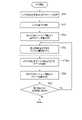
いま、マンモグラフィ装置1では、MLO方向に沿ってマンモグラフィ画像が撮影された後、CC方向に沿ってマンモグラフィ画像が撮影される。マンモグラフィ装置1の記憶回路22には、各マンモグラフィ画像と、各マンモグラフィ画像の撮像角度を示す角度情報とが記憶される。また図6に示すように、マンモグラフィ装置1では、乳房のトモシンセシス撮影が行われ(ステップST10)、トモシンセシス撮影により得られた複数の断層画像が記憶回路22に記憶される。このとき、記憶回路22は、DICOM規格に準拠した医用画像データとして、複数の断層画像を含む医用画像ファイルを記憶したとする。 Now, in the
ステップST10の後、マンモグラフィ装置1の処理回路26は、入力インタフェース23の操作に応じて、各マンモグラフィ画像をディスプレイ27に表示させる。また、処理回路26は、入力インタフェース23の操作に応じて、図7に示すように、右乳房の各マンモグラフィ画像上に、関心領域P1を設定(ポインティング)する。なお、図7に示す2つのマンモグラフィ画像のうち、左側がCC方向で撮影されたマンモグラフィ画像であり、右側がMLO方向で撮影されたマンモグラフィ画像である。処理回路26は、超音波診断支援機能により、関心領域P1の位置を含んで各撮影方向に沿った2本の直線を乳房正面のボディマークBM上に描画する。例えば、CC方向に沿った直線は縦方向の直線として描画され、MLO方向に沿った直線は斜め方向の直線として描画される。処理回路26は、ボディマークBMの画像を各マンモグラフィ画像に対応付けて記憶回路22に保存する。 After step ST10, the
同様に、マンモグラフィ装置1の処理回路26は、入力インタフェース23の操作に応じて、複数の断層画像のうちの第2断層画像をディスプレイ27に表示させる。また、処理回路26は、入力インタフェース23の操作に応じて、表示中の第2断層画像上に、関心領域を設定(ポインティング)する(ステップST20)。 Similarly, the
ステップST20の後、処理回路26のスケール処理機能26bは、記憶回路22に記憶された複数の断層画像のうち、少なくとも1つの第2断層画像上でニップルからの3次元の距離を示すスケール画像を準備する(ステップST30)。例えば、スケール処理機能26bは、複数の断層画像のうちで乳房のニップルを含むいずれかの第1断層画像のスライス位置、第2断層画像のスライス位置、当該第1断層画像上におけるニップルの2次元の位置に基づき、スケール画像を生成する。なお、ステップST30としては、スケール画像を生成する処理に代えて、予め記憶回路22に記憶した複数のスケール画像からスケール画像を選択する処理を用いてもよい。以下では、主に、スケール画像を生成する処理について述べる。 After step ST20, the scale processing function 26b of the
このステップST30は、例えば、図8AのステップST31~ST37に示すように実行される。但し、ステップST30は、ステップST31~ST37の処理に限定されない。例えば、ステップST35以外の各ステップST31~ST34,ST36,ST37は適宜、省略してもよい。以下、ステップST31~ST37を説明する。 This step ST30 is executed, for example, as shown in steps ST31 to ST37 of FIG. 8A. However, step ST30 is not limited to the processing of steps ST31 to ST37. For example, steps ST31 to ST34, ST36, and ST37 other than step ST35 may be omitted as appropriate. Hereinafter, steps ST31 to ST37 will be described.
始めに、処理回路26は、図9に示すように、スケールボタンB1の操作に応じて、ニップルを含む各マンモグラフィ画像上に、基準スケールを表示する。なお、基準スケールの表示中に、スケールボタンB1を操作すると、基準スケールが画面から消去される。 First, as shown in FIG. 9, the
また、処理回路26は、断層画像についても同様に、スケールボタンB1の操作に応じて、複数の断層画像のうちでニップルを含むいずれかの第1断層画像上に、基準スケールを表示する(ステップST31)なお、基準スケールの表示中に、スケールボタンB1を操作すると、基準スケールが画面から消去される。 Similarly, for the tomographic image, the
ステップST31の後、処理回路26は、操作者による基準スケールのスライド操作に応じて、図10に示すように、基準スケールの中心をニップルの位置に移動させる。これにより、表示中の右乳房の各マンモグラフィ画像上でニップルの2次元の位置が特定される。なお、反対側の左乳房の各マンモグラフィ画像については、図11に示すように、LボタンB3を操作すると、表示中の各マンモグラフィ画像に代えて、ディスプレイ27に表示される。また、左乳房の各マンモグラフィ画像の表示中に、RボタンB2を操作すると、表示中の各マンモグラフィ画像に代えて、右乳房の各マンモグラフィ画像が新たに表示される。 After step ST31, the
また、処理回路26は、第1断層画像についても同様に、操作者による基準スケールのスライド操作に応じて、基準スケールの中心をニップルの位置に移動させる。これにより、表示中の第1断層画像上におけるニップルの2次元の位置が特定される(ステップST32)。 Similarly, the
ステップST32の後、処理回路26の処理制御機能26aは、図12に示すように、DICOMのオーバーレイ情報i2として、ニップルの2次元の位置を中心とした基準スケール画像sc(t25)を医用画像ファイルFAに組み込む(ステップST33)。符号“t25”は、ニップルの2次元の位置を特定した第1断層画像のスライス位置t25を示す。ここで、ニップルの2次元の位置に対応する基準位置等は、オーバーレイ情報i2内のオーバーレイ付随情報i21に組み込まれる。基準スケール画像sc(t25)のビットマップデータ(弧状の部分)及び文字列データ(D2,D4,…)は、オーバーレイ情報i2内のオーバーレイ画像データi22に組み込まれる。なお、この医用画像ファイルFAは、医用画像データi3として複数の断層画像を有している。符号“i1”は、DICOM付帯情報を示す。しかる後、医用画像ファイルFAは、記憶回路22に更新記憶される。 After step ST32, as shown in FIG. 12, the
ステップST33の後、処理回路26のスケール処理機能26bは、ステップST20で設定された関心領域を含む少なくとも1つの第2断層画像のスライス位置を読み出す(ステップST34)。 After step ST33, the scale processing function 26b of the
ステップST34の後、スケール処理機能26bは、ステップST32でニップルの2次元の位置を特定した第1断層画像のスライス位置、ステップST34で読み出したスライス位置、当該ニップルの2次元の位置に基づき、第2断層画像上でニップルからの3次元の距離を示すスケール画像を生成する(ステップST35)。言い換えると、ニップルを含む第1断層画像上でニップルを特定すると、別の第2断層画像に重畳されるスケールが描画される。 After step ST34, the scale processing function 26b is based on the slice position of the first tomographic image in which the two-dimensional position of the nipple is specified in step ST32, the slice position read out in step ST34, and the two-dimensional position of the nipple. A scale image showing a three-dimensional distance from the nipple is generated on the two tomographic image (step ST35). In other words, when the nipple is specified on the first tomographic image including the nipple, a scale superimposed on another second tomographic image is drawn.
具体的には例えば、図13に示すように、乳房の50枚の断層画像は、スライス位置が“t1”~“t50”で表され、それぞれスライス厚が1mmであり、互いに隣接しているとする。また、1枚目の断層画像のスライス位置t1と圧迫板17aの圧迫面との間の距離は、1mmであり、10枚目の断層画像のスライス位置t10と圧迫板17aの圧迫面との間の距離は、10mmであるとする。以下同様にして、25枚目の断層画像のスライス位置t25と圧迫板17aの圧迫面との間の距離は、25mmであり、50枚目の断層画像のスライス位置t50と圧迫板17aの圧迫面との間の距離は、50mmであるとする。また、スライス位置t25におけるニップルの2次元の位置を黒丸で示す。図13中、ニップル(黒丸)からの3次元の距離D2,D4,…を、弧状の曲線で示すとする。なお、当該3次元の距離D2,D4,…は、それぞれ半径D2,D4,…の半球の殻のように示されるが、図13が平面のために弧状の曲線で描かれている。このことは、図14中のニップルからの3次元の距離D2,D4,…も同様である。 Specifically, for example, as shown in FIG. 13, 50 tomographic images of breasts have slice positions represented by “t1” to “t50”, each having a slice thickness of 1 mm, and are adjacent to each other. do. The distance between the slice position t1 of the first tomographic image and the compression surface of the
また例えば、図14中、スライス位置t25の断層画像は、ニップルを含む第1断層画像であり、スライス位置t10の断層画像は、関心領域を含む第2断層画像であるとする。また、スライス位置t25の第1断層画像と、スライス位置t10の第2断層画像との間の距離z(t10)は、スライス位置t25とスライス位置t10との間の断層画像が15枚分あり、スライス厚が1mmであるので、15×1=15mmであるとする。あるいは、当該距離z(t10)は、スライス位置t10,t25と圧迫板17aの圧迫面との間の距離(10mm、25mm)の差分として求めてもよい。 Further, for example, in FIG. 14, the tomographic image at the slice position t25 is the first tomographic image including the nipple, and the tomographic image at the slice position t10 is the second tomographic image including the region of interest. Further, the distance z (t10) between the first tomographic image at the slice position t25 and the second tomographic image at the slice position t10 includes 15 tomographic images between the slice position t25 and the slice position t10. Since the slice thickness is 1 mm, it is assumed that 15 × 1 = 15 mm. Alternatively, the distance z (t10) may be obtained as the difference in the distance (10 mm, 25 mm) between the slice positions t10, t25 and the compression surface of the
また、スライス位置tiの第2断層画像は、スライス位置t25の第1断層画像から離れるに従い、第1断層画像上のニップルからの2次元の距離Dnに対し、第2断層画像上の2次元の距離Dn(ti)が短くなっていく。例えば図14、図15(a)及び図15(b)に示すように、ニップルからの距離D4の場合、スライス位置t25の第1断層画像上の2次元の距離D4(t25)に比べ、スライス位置t10の第2断層画像上の2次元の距離D4(t10)が短くなる(D4(t10)<D(t25))。 Further, the second tomographic image at the slice position ti becomes two-dimensional on the second tomographic image with respect to the two-dimensional distance Dn from the nipple on the first tomographic image as the distance from the first tomographic image at the slice position t25 increases. The distance Dn (ti) becomes shorter. For example, as shown in FIGS. 14, 15 (a) and 15 (b), in the case of the distance D4 from the nipple, the slice is compared with the two-dimensional distance D4 (t25) on the first tomographic image at the slice position t25. The two-dimensional distance D4 (t10) on the second tomographic image at position t10 becomes shorter (D4 (t10) <D (t25)).
具体的には、スライス位置tiの第2断層画像上の2次元の距離Dn(ti)は、ピタゴラスの定理に基づき、以下のように算出可能である。但し「^」は、べき乗を表す記号である。 Specifically, the two-dimensional distance Dn (ti) on the second tomographic image of the slice position ti can be calculated as follows based on the Pythagorean theorem. However, "^" is a symbol representing a power.
Dn(ti)=(Dn(t25)^2-z(ti)^2)^(1/2)
例えばスライス位置t10の第2断層画像上の2次元の距離D4(t10)の場合、図14及び以下に示すように算出可能である。Dn (ti) = (Dn (t25) ^ 2-z (ti) ^ 2) ^ (1/2)
For example, in the case of the two-dimensional distance D4 (t10) on the second tomographic image at the slice position t10, it can be calculated as shown in FIG. 14 and the following.
D4(t10)=(D4(t25)^2-z(t10)^2)^(1/2)
スケール処理機能26bは、得られた2次元の距離D4(t10)を示す弧状の曲線を描画することにより、(スライス位置t10の第2断層画像に重畳される)スケール画像のうち、3次元の距離D4を示す曲線を生成する。以下、同様にして、スケール処理機能26bは、様々な2次元の距離D5(t10),D6(t10),…を示す弧状の曲線を描画することにより、(スライス位置t10の断層画像に重畳される)様々な3次元の距離D5,D6,…を示すスケール画像を生成する。補足すると、図14及び図15(b)に示すように、スライス位置t10に用いるスケール画像の場合、ニップルからの3次元の距離D4,…は、ニップルの2次元の位置からの2次元の距離D4(t10),…を示す曲線により表現されている。D4 (t10) = (D4 (t25) ^ 2-z (t10) ^ 2) ^ (1/2)
The scale processing function 26b draws an arc-shaped curve indicating the obtained two-dimensional distance D4 (t10), whereby the three-dimensional scale image (superimposed on the second tomographic image at the slice position t10) is three-dimensional. Generate a curve showing the distance D4. Hereinafter, similarly, the scale processing function 26b is superimposed on the tomographic image at the slice position t10 by drawing arcuate curves indicating various two-dimensional distances D5 (t10), D6 (t10), .... ) Generates scale images showing various three-dimensional distances D5, D6, .... Supplementally, as shown in FIGS. 14 and 15 (b), in the case of the scale image used for the slice position t10, the three-dimensional distances D4, ... From the nipple are the two-dimensional distances from the two-dimensional position of the nipple. It is represented by a curve showing D4 (t10), ....
また、処理回路26の表示制御機能26cは、スライス位置t10の第2断層画像上に、当該スケール画像を重畳表示するようにディスプレイ27を制御する。 Further, the
なお、以上のようなステップST35は、スケール画像を生成する処理に代えて、図8Bに“ST35a”として示すように、予め記憶回路22に記憶した複数のスケール画像からスケール画像を選択する処理を用いてもよい。この場合、記憶回路22は、複数の断層画像と、乳房のニップルからの3次元の距離を示す複数のスケール画像とを記憶している。具体的には例えば、記憶回路22は、第1断層画像のスライス位置と第2断層画像のスライス位置との間の距離又は距離範囲と、各々のスケール画像とを関連付けて記憶しておく。 In step ST35 as described above, instead of the process of generating a scale image, a process of selecting a scale image from a plurality of scale images stored in advance in the
表示制御機能26cは、第1断層画像のスライス位置と第2断層画像のスライス位置との間の距離に応じたスケール画像を複数のスケール画像より選択する。例えば、表示制御機能26cは、第1断層画像のスライス位置と第2断層画像のスライス位置との間の距離に基づいて、記憶回路22内のスケール画像を選択的に読み出す。 The
しかる後、表示制御機能26cは、選択されたスケール画像を、第1断層画像上におけるニップルの2次元の位置に基づいて第2断層画像上に重畳表示するようにディスプレイ27を制御する。これにより、ステップST35aに変形した場合のステップST35が終了する。 After that, the
ステップST35(又はST35a)の後、処理回路26の処理制御機能26aは、ステップST33と同様に、DICOMのオーバーレイ情報i2として、当該準備したスケール画像を医用画像ファイルFAに組み込む(ステップST36)。この医用画像ファイルFAは、ステップST33で用いたものである。ニップルの2次元の位置(XY座標)は、ステップST32で特定された位置と同じであり、ニップルの2次元の位置に対応する基準位置等は、オーバーレイ情報i2内のオーバーレイ付随情報i21に組み込まれる。スケール画像のビットマップデータ及び文字列データは、ステップST33と同様に、オーバーレイ情報i2内のオーバーレイ画像データi22に組み込まれる。しかる後、医用画像ファイルFAは、記憶回路22に更新記憶される。 After step ST35 (or ST35a), the
ステップST36の後、スケール処理機能26bは、関心領域を含む他の第2断層画像があるか否かを判定し(ステップST37)、他の第2断層画像がある場合にはステップST34~ST36の処理を繰り返し実行する。2回目以降のステップST35では、スケール処理機能26bは、他のスライス位置ti及び距離Dnの場合にも同様にして、距離Dn(ti)を示す弧状の曲線を描画することにより、(スライス位置tiの断層画像に重畳される)スケール画像を生成すればよい。 After step ST36, the scale processing function 26b determines whether or not there is another second tomographic image including the region of interest (step ST37), and if there is another second tomographic image, steps ST34 to ST36. Repeat the process. In the second and subsequent steps ST35, the scale processing function 26b draws an arcuate curve indicating the distance Dn (ti) in the same manner for the other slice position ti and the distance Dn (slice position ti). A scale image (superimposed on the tomographic image of) may be generated.
一方、ステップST37の判定の結果、否の場合には、ステップST30を終了してステップST40に移行する。 On the other hand, if the result of the determination in step ST37 is no, step ST30 is terminated and the process proceeds to step ST40.
ステップST40において、マンモグラフィ装置1の処理回路26は、入力インタフェース23の操作に応じて、複数の断層画像、スケール画像及び基準スケール画像を含む医用画像ファイルFAをネットワークNwに出力する。この医用画像ファイルFAは、DICOM規格に準拠した通信により、ネットワークNwを介して超音波診断装置30又は医用情報処理装置50に送信される。同様に、マンモグラフィ装置1の処理回路26は、入力インタフェース23の操作に応じて、各マンモグラフィ画像及びボディマークBMの画像をネットワークNwに出力する。この各マンモグラフィ画像及びボディマークBMの画像は、DICOM規格に準拠した通信により、ネットワークNwを介して超音波診断装置30又は医用情報処理装置50に送信される。ここで、スケール画像を重畳した断層画像と、ボディマークBMの画像とは、互いに同一の装置に送信されてもよく、互いに異なる装置に送信されてもよい。すなわち、超音波検査の際に、スケール画像を重畳した断層画像と、ボディマークBMの画像とは、互いに同一の装置に表示されてもよく、互いに異なる装置に表示されてもよい。本実施形態では、医用画像ファイルFA、各マンモグラフィ画像及びボディマークBMの画像が、それぞれビューワとしての医用情報処理装置50に送信されたものとする。また、医用情報処理装置50は、超音波診断装置30の近傍に配置されているとする。 In step ST40, the
ステップST40の後、医用情報処理装置50の処理回路55は、送信された医用画像ファイルFA、各マンモグラフィ画像及びボディマークBMの画像を記憶回路51に記憶する。処理回路55の表示制御機能55cは、入力インタフェース52の操作に応じて、医用画像ファイルFAから関心領域を含む第2断層画像をディスプレイ53に表示させる(ステップST50)。また、表示制御機能55cは、入力インタフェース52の操作に応じて、記憶回路51内の各マンモグラフィ画像及びボディマークBMの画像をディスプレイ53に表示させる。但し、各マンモグラフィ画像については表示を省略してもよい。 After step ST40, the
ステップST50の後、表示制御機能55cは、入力インタフェース52の操作に応じて、関心領域を含む第2断層画像上に、スケール画像を重畳表示するようにディスプレイ53を制御する(ステップST60)。これにより、ディスプレイ53には、ボディマークBMの画像と、スケール画像が重畳された第2断層画像とがそれぞれ表示される。従って、超音波検査の際に、医師等の操作者は、ボディマークBMの画像から関心領域の大体の位置が分かり、第2断層画像上のスケール画像により、第2断層画像内の関心領域に関し、ニップルからの距離が分かる。従って、超音波診断装置30による超音波検査の際に、超音波プローブ31を用いた関心領域のスキャンを、より容易に実行することができる。 After step ST50, the
ステップST60の後、超音波プローブ31を用いた関心領域のスキャンにより、超音波診断装置30は、超音波プローブ31の出力に基づいて、超音波画像を生成及び表示し、超音波画像の検査が実行される。表示された超音波画像内の関心領域などが確認された後、確認に用いた超音波画像が記憶回路35に保存され、超音波画像の検査が終了する。この超音波画像は、DICOMの医用画像データとして、医用画像ファイルに組み込まれて記憶回路35に保存されてもよい。 After step ST60, by scanning the region of interest using the
超音波検査の終了後、例えば、医用情報処理装置50は、断層画像を含む医用画像ファイルFAを、読影医のコンピュータに送信する。また、超音波診断装置30は、超音波画像を含む医用画像ファイルを、読影医のコンピュータに送信する。なお、読影医のコンピュータが医用情報処理装置50の場合、医用情報処理装置50は医用画像ファイルFAを送信せず、超音波診断装置30は医用画像ファイルを医用情報処理装置50に送信する。 After the completion of the ultrasonic examination, for example, the medical
読影医のコンピュータは、それぞれ医用画像データを受信し、読影医の操作により、関心領域を含む断層画像と、超音波画像とをディスプレイに表示する。なお、読影時には、スケール画像が不要であるため、読影医の操作により、スケール画像は表示されない。読影医のコンピュータは、読影医の操作により、断層画像及び超音波画像に基づくレポートを作成し、処理を終了する。 The computer of the interpreting doctor receives the medical image data, and by the operation of the interpreting doctor, the tomographic image including the region of interest and the ultrasonic image are displayed on the display. Since the scale image is not required at the time of image interpretation, the scale image is not displayed by the operation of the image interpreting doctor. The computer of the interpreting doctor creates a report based on the tomographic image and the ultrasonic image by the operation of the interpreting doctor, and finishes the process.
上述したように第1の実施形態によれば、乳房のトモシンセシス撮影により得られた複数の断層画像のうちで乳房のニップルを含むいずれかの第1断層画像のスライス位置、複数の断層画像のうちで少なくとも1つの第2断層画像のスライス位置、当該第1断層画像上におけるニップルの2次元の位置に基づき、第2断層画像上でニップルからの3次元の距離を示すスケール画像を生成する。第2断層画像上にスケール画像を重畳表示するようにディスプレイを制御する。例えば、ニップルを含む第1断層画像上でニップルを特定すると、別の第2断層画像に重畳されるスケールが描画される。このように、第2断層画像にスケール画像を重畳表示することにより、第2断層画像内の関心領域に関し、ニップルからの距離を示すことができる。 As described above, according to the first embodiment, among the plurality of tomographic images obtained by tomosynthesis imaging of the breast, the slice position of any of the first tomographic images including the nipple of the breast, among the plurality of tomographic images. Generates a scale image showing the three-dimensional distance from the nipple on the second tomographic image based on the slice position of at least one second tomographic image and the two-dimensional position of the nipple on the first tomographic image. The display is controlled so that the scale image is superimposed and displayed on the second tomographic image. For example, when a nipple is specified on a first tomographic image including a nipple, a scale superimposed on another second tomographic image is drawn. By superimposing the scale image on the second tomographic image in this way, it is possible to indicate the distance from the nipple with respect to the region of interest in the second tomographic image.
また例えば、第1の実施形態によれば、スケール画像が、ニップルに対して凹の弧状の部分を含んでいる。これにより、第2断層画像における任意の位置の関心領域に対し、ニップルからの距離を示すことができる。 Also, for example, according to the first embodiment, the scale image includes a concave arcuate portion with respect to the nipple. This makes it possible to indicate the distance from the nipple with respect to the region of interest at an arbitrary position in the second tomographic image.
また例えば、第1の実施形態によれば、第2断層画像のうちの少なくとも1つが、乳房のニップルを含む断層画像である。これにより、ニップルを含む第1断層画像と、第2断層画像とが同一の断層画像である場合でも、当該断層画像内の関心領域に関し、ニップルからの距離を示すことができる。 Also, for example, according to the first embodiment, at least one of the second tomographic images is a tomographic image including a breast nipple. Thereby, even when the first tomographic image including the nipple and the second tomographic image are the same tomographic image, it is possible to indicate the distance from the nipple with respect to the region of interest in the tomographic image.
また例えば、第1の実施形態によれば、複数の断層画像と、乳房のニップルからの2次元の距離を示す基準スケール画像とを記憶する。第1断層画像上に、ニップルの2次元の位置に基づいて基準スケール画像を重畳表示するようにディスプレイを制御する。このように、ニップルを含む第1断層画像に対しては、記憶された基準スケール画像を重畳表示することにより、スケール画像を生成する処理を省略することができる。 Also, for example, according to the first embodiment, a plurality of tomographic images and a reference scale image showing a two-dimensional distance from the nipple of the breast are stored. The display is controlled so that the reference scale image is superimposed and displayed on the first tomographic image based on the two-dimensional position of the nipple. As described above, the process of generating the scale image can be omitted by superimposing and displaying the stored reference scale image on the first tomographic image including the nipple.
また例えば、第1の実施形態の変形動作によれば、複数の断層画像と、乳房のニップルからの3次元の距離を示す複数のスケール画像とを記憶する。第1断層画像のスライス位置と第2断層画像のスライス位置との間の距離に応じたスケール画像を複数のスケール画像より選択する。選択されたスケール画像を、第1断層画像上におけるニップルの2次元の位置に基づいて第2断層画像上に重畳表示するようにディスプレイを制御する。このように、記憶した複数のスケール画像から選択したスケール画像を重畳表示することにより、スケール画像を生成せずに、第2断層画像上でニップルからの3次元の距離を示すことができる。 Further, for example, according to the deformation operation of the first embodiment, a plurality of tomographic images and a plurality of scale images showing a three-dimensional distance from the breast nipple are stored. A scale image corresponding to the distance between the slice position of the first tomographic image and the slice position of the second tomographic image is selected from a plurality of scale images. The display is controlled so that the selected scale image is superimposed and displayed on the second tomographic image based on the two-dimensional position of the nipple on the first tomographic image. By superimposing and displaying the scale image selected from the plurality of stored scale images in this way, it is possible to show the three-dimensional distance from the nipple on the second tomographic image without generating the scale image.
また例えば、第1の実施形態によれば、DICOM規格に準拠した医用画像データとして複数の断層画像を含む医用画像ファイルを記憶する。スケール画像及び基準スケール画像をDICOMのオーバーレイ情報として医用画像ファイルに組み込む。これにより、例えば、DICOM規格に準拠した通信により、医用画像ファイルを送信することができる。 Further, for example, according to the first embodiment, a medical image file including a plurality of tomographic images is stored as medical image data conforming to the DICOM standard. The scale image and the reference scale image are incorporated into the medical image file as DICOM overlay information. Thereby, for example, a medical image file can be transmitted by communication conforming to the DICOM standard.
<第2の実施形態>
次に、第2の実施形態に係る医用情報処理システムについて説明する。以下の説明は、理解を容易にするため、略同一部分の説明を省略し、主に、異なる部分について述べる。<Second embodiment>
Next, the medical information processing system according to the second embodiment will be described. In the following description, for the sake of ease of understanding, the description of substantially the same part is omitted, and the description of different parts is mainly described.
第2の実施形態は、第1の実施形態の変形例であり、スライス位置毎のスケール画像を生成せず、全てのスライス位置で同一の基準スケール画像を用いる構成となっている。なお、本実施形態の「基準スケール画像」は、他にスケール画像がないので、単に「スケール画像」と呼んでもよい。 The second embodiment is a modification of the first embodiment, and is configured to use the same reference scale image at all slice positions without generating a scale image for each slice position. Since there is no other scale image, the "reference scale image" of the present embodiment may be simply called a "scale image".
これに伴い、マンモグラフィ装置1の記憶回路22は、複数の断層画像と、第1断層画像上におけるニップルからの2次元の距離を示す基準スケール画像とを記憶する。なお、記憶回路22は、DICOM規格に準拠した医用画像データとして、複数の断層画像を含む医用画像ファイルを記憶してもよい。このとき、基準スケール画像は、DICOMのオーバーレイ情報として医用画像ファイルに組み込まれていてもよい。 Along with this, the
また、処理回路26の処理制御機能26aは、DICOM規格に準拠した複数の断層画像を含む医用画像ファイルを記憶回路22が記憶している場合、基準スケール画像をDICOMのオーバーレイ情報として医用画像ファイルに組み込む機能を含んでいる。 Further, when the
スケール処理機能26bは、「第1断層画像のスライス位置、第2断層画像のスライス位置、第1断層画像上におけるニップルの2次元の位置に基づき、スケール画像を生成する」機能が省略される。 The scale processing function 26b omits the function of "generating a scale image based on the slice position of the first tomographic image, the slice position of the second tomographic image, and the two-dimensional position of the nipple on the first tomographic image".
表示制御機能26cは、複数の断層画像のうちでニップルを含むいずれかの第1断層画像から特定された当該ニップルの2次元の位置に基づいて、複数の断層画像のうちで少なくとも1つの第2断層画像上に基準スケール画像を重畳表示するようにディスプレイ27を制御する。これにより、第2の実施形態においては、スケール画像に代えて、基準スケール画像がディスプレイ27に重畳表示される。 The
超音波診断装置30の記憶回路35は、複数の断層画像と、乳房のニップルからの距離を示す基準スケール画像とを記憶する。なお、記憶回路35は、DICOM規格に準拠した医用画像データとして、複数の断層画像を含む医用画像ファイルを記憶してもよい。このとき、基準スケール画像は、DICOMのオーバーレイ情報として医用画像ファイルに組み込まれていてもよい。 The
また、処理回路40の処理制御機能40aは、DICOM規格に準拠した複数の断層画像を含む医用画像ファイルを記憶回路35が記憶している場合、基準スケール画像をDICOMのオーバーレイ情報として医用画像ファイルに組み込む機能を含んでいる。 Further, when the
スケール処理機能40bは、「第1断層画像のスライス位置、第2断層画像のスライス位置、ニップルの2次元の位置に基づき、スケール画像を生成する」機能が省略される。 The
表示制御機能40cは、複数の断層画像のうちでニップルを含むいずれかの第1断層画像から特定された当該ニップルの2次元の位置に基づいて、複数の断層画像のうちで少なくとも1つの第2断層画像上に基準スケール画像を重畳表示するようにディスプレイ37を制御する。 The
医用情報処理装置50の記憶回路51は、複数の断層画像と、乳房のニップルからの距離を示す基準スケール画像とを記憶する。なお、記憶回路51は、DICOM規格に準拠した医用画像データとして、複数の断層画像を含む医用画像ファイルを記憶してもよい。このとき、基準スケール画像は、DICOMのオーバーレイ情報として医用画像ファイルに組み込まれていてもよい。 The
また、処理回路55の処理制御機能55aは、DICOM規格に準拠した複数の断層画像を含む医用画像ファイルを記憶回路51が記憶している場合、基準スケール画像をDICOMのオーバーレイ情報として医用画像ファイルに組み込む機能を含んでいる。 Further, when the
スケール処理機能55bは、「第1断層画像のスライス位置、第2断層画像のスライス位置、ニップルの2次元の位置に基づき、スケール画像を生成する」機能が省略される。 The scale processing function 55b omits the function of "generating a scale image based on the slice position of the first tomographic image, the slice position of the second tomographic image, and the two-dimensional position of the nipple".
表示制御機能55cは、複数の断層画像のうちでニップルを含むいずれかの第1断層画像から特定された当該ニップルの2次元の位置に基づいて、複数の断層画像のうちで少なくとも1つの第2断層画像上に基準スケール画像を重畳表示するようにディスプレイ53を制御する。 The
他の構成は、第1の実施形態と同様である。 Other configurations are the same as in the first embodiment.
以上のような構成によれば、例えば図16に示すように、前述同様にステップST10,ST20,ST31~ST34を実行した後、ステップST35のスケール画像を生成する処理を実行しない。 According to the above configuration, for example, as shown in FIG. 16, after executing steps ST10, ST20, ST31 to ST34 in the same manner as described above, the process of generating the scale image of step ST35 is not executed.
ステップST34の後、処理回路26の表示制御機能26cは、複数の断層画像のうち、ステップST34で読み出したスライス位置の断層画像上に、ステップST32で特定されたニップルの2次元の位置に基づいて基準スケール画像を重畳表示するようにディスプレイ27を制御する。 After step ST34, the
処理制御機能26aは、ステップST33と同様に、DICOMのオーバーレイ情報i2として、記憶回路22内の基準スケール画像を医用画像ファイルFAに組み込む(ステップST36a)。この医用画像ファイルFAは、ステップST33で用いたものである。オーバーレイ画像データi22は、ステップST33で組み込まれている。基準スケール画像を重畳表示させる断層画像のスライス位置(又はスライス番号)がオーバーレイ付随情報i21に組み込まれる。しかる後、医用画像ファイルFAは、記憶回路22に更新記憶される。 Similar to step ST33, the
ステップST36aの後、スケール処理機能26bは、関心領域を含む他の断層画像があるか否かを判定し(ステップST37)、他の断層画像がある場合にはステップST34~ST36aの処理を繰り返し実行する。 After step ST36a, the scale processing function 26b determines whether or not there is another tomographic image including the region of interest (step ST37), and if there is another tomographic image, the processing of steps ST34 to ST36a is repeatedly executed. do.
一方、ステップST37の判定の結果、否の場合には、ステップST30を終了してステップST40に移行する。以下、前述同様に、ステップST40~ST70が実行される。 On the other hand, if the result of the determination in step ST37 is no, step ST30 is terminated and the process proceeds to step ST40. Hereinafter, steps ST40 to ST70 are executed in the same manner as described above.
従って、第2の実施形態によれば、乳房のトモシンセシス撮影により得られた複数の断層画像と、第1断層画像上におけるニップルからの2次元の距離を示す基準スケール画像とを記憶する。第1断層画像から特定された当該ニップルの2次元の位置に基づいて、複数の断層画像のうちで少なくとも1つの第2断層画像上に基準スケール画像を重畳表示するようにディスプレイを制御する。このように、断層画像に基準スケール画像を重畳表示することにより、断層画像上のニップルの有無によらず、任意の断層画像上において、ニップルからの2次元の距離を示すことができる。また、第1の実施形態に比べ、スケール画像の生成処理を省略したため、装置の負荷を低減させることができる。 Therefore, according to the second embodiment, a plurality of tomographic images obtained by tomosynthesis imaging of the breast and a reference scale image showing a two-dimensional distance from the nipple on the first tomographic image are stored. The display is controlled so that the reference scale image is superimposed and displayed on at least one second tomographic image among the plurality of tomographic images based on the two-dimensional position of the nipple identified from the first tomographic image. By superimposing the reference scale image on the tomographic image in this way, it is possible to show the two-dimensional distance from the nipple on any tomographic image regardless of the presence or absence of the nipple on the tomographic image. Further, since the scale image generation process is omitted as compared with the first embodiment, the load on the apparatus can be reduced.
また例えば、第2の実施形態によれば、DICOM規格に準拠した医用画像データとして複数の断層画像を含む医用画像ファイルを記憶し、基準スケール画像をDICOMのオーバーレイ情報として医用画像ファイルに組み込む。これにより、例えば、DICOM規格に準拠した通信により、医用画像ファイルを送信することができる。 Further, for example, according to the second embodiment, a medical image file including a plurality of tomographic images is stored as medical image data conforming to the DICOM standard, and a reference scale image is incorporated into the medical image file as DICOM overlay information. Thereby, for example, a medical image file can be transmitted by communication conforming to the DICOM standard.
以上説明した少なくとも一つの実施形態によれば、断層画像上に、第1断層画像上におけるニップルの2次元の位置に基づいて、第2断層画像上にスケール画像(又は基準スケール画像)を重畳表示するため、ニップルからの距離を示すことができる。 According to at least one embodiment described above, a scale image (or a reference scale image) is superimposed and displayed on the second tomographic image based on the two-dimensional position of the nipple on the first tomographic image. Therefore, the distance from the nipple can be indicated.
上記説明において用いた「プロセッサ」という文言は、例えば、CPU(central processing unit)、GPU(Graphics Processing Unit)、或いは、特定用途向け集積回路(Application Specific Integrated Circuit:ASIC))、プログラマブル論理デバイス(例えば、単純プログラマブル論理デバイス(Simple Programmable Logic Device:SPLD)、複合プログラマブル論理デバイス(Complex Programmable Logic Device:CPLD)、及びフィールドプログラマブルゲートアレイ(Field Programmable Gate Array:FPGA))等の回路を意味する。プロセッサは記憶回路に保存されたプログラムを読み出し実行することで機能を実現する。なお、記憶回路にプログラムを保存する代わりに、プロセッサの回路内にプログラムを直接組み込むよう構成しても構わない。この場合、プロセッサは回路内に組み込まれたプログラムを読み出し実行することで機能を実現する。なお、本実施形態の各プロセッサは、プロセッサごとに単一の回路として構成される場合に限らず、複数の独立した回路を組み合わせて1つのプロセッサとして構成し、その機能を実現するようにしてもよい。さらに、図1における複数の構成要素を1つのプロセッサへ統合してその機能を実現するようにしてもよい。 The term "processor" used in the above description means, for example, a CPU (central processing unit), a GPU (Graphics Processing Unit), or an application specific integrated circuit (ASIC), a programmable logic device (for example). , Simple Programmable Logic Device (SPLD), Complex Programmable Logic Device (CPLD), and Field Programmable Gate Array (FPGA)). The processor realizes the function by reading and executing the program stored in the storage circuit. Instead of storing the program in the storage circuit, the program may be directly embedded in the circuit of the processor. In this case, the processor realizes the function by reading and executing the program embedded in the circuit. It should be noted that each processor of the present embodiment is not limited to the case where each processor is configured as a single circuit, and a plurality of independent circuits may be combined to form one processor to realize its function. good. Further, a plurality of components in FIG. 1 may be integrated into one processor to realize the function.
各実施形態における記憶回路22,35,51は、特許請求の範囲における記憶手段の一例である。各実施形態における処理回路26,40,55及びスケール処理機能26b,40b,55bは、特許請求の範囲における生成手段の一例である。各実施形態における処理回路26,40,55及び表示制御機能26c,40c,55cは、特許請求の範囲における表示制御手段の一例である。各実施形態における処理回路26,40,55及び処理制御機能26a,40a,55aは、特許請求の範囲における組込手段の一例である。第2の実施形態における基準スケール画像は、請求項6、7におけるスケール画像の一例である。 The
なお、本発明のいくつかの実施形態を説明したが、これらの実施形態は、例として提示したものであり、発明の範囲を限定することは意図していない。これら実施形態は、その他の様々な形態で実施されることが可能であり、発明の要旨を逸脱しない範囲で、種々の省略、置き換え、変更を行うことができる。これら実施形態やその変形は、発明の範囲や要旨に含まれると同様に、特許請求の範囲に記載された発明とその均等の範囲に含まれる。 Although some embodiments of the present invention have been described, these embodiments are presented as examples and are not intended to limit the scope of the invention. These embodiments can be implemented in various other embodiments, and various omissions, replacements, and changes can be made without departing from the gist of the invention. These embodiments and variations thereof are included in the scope of the invention described in the claims and the equivalent scope thereof, as are included in the scope and gist of the invention.
1…マンモグラフィ装置、3…X線撮像装置、5…コンピュータ装置、10…基台部、11…Cアーム、12…軸部、15…X線発生装置、16…撮影台、16a…載置面、17…圧迫ユニット、17a…圧迫板、18…X線管、19…高電圧発生器、21…データ収集部、22,35,51…記憶回路、23,36,52…入力インタフェース、24…撮影制御回路、25…画像発生回路、26,40,55…処理回路、26a,40a,55a…処理制御機能、26b,40b,55b…スケール処理機能、26c,40c,55c…表示制御機能、27,37,53…ディスプレイ、28…システム制御回路、29,39,54…ネットワークインタフェース、30…超音波診断装置、31…超音波プローブ、32…装置本体、33…送受信回路、34…画像生成回路、38…画像DB回路、50…医用情報処理装置、Nw…ネットワーク。 1 ... Mammography device, 3 ... X-ray imaging device, 5 ... Computer device, 10 ... Base, 11 ... C arm, 12 ... Shaft, 15 ... X-ray generator, 16 ... Shooting table, 16a ... Mounting surface , 17 ... compression unit, 17a ... compression plate, 18 ... X-ray tube, 19 ... high voltage generator, 21 ... data acquisition unit, 22,35,51 ... storage circuit, 23,36,52 ... input interface, 24 ... Shooting control circuit, 25 ... image generation circuit, 26, 40, 55 ... processing circuit, 26a, 40a, 55a ... processing control function, 26b, 40b, 55b ... scale processing function, 26c, 40c, 55c ... display control function, 27 , 37, 53 ... Display, 28 ... System control circuit, 29, 39, 54 ... Network interface, 30 ... Ultrasonic diagnostic device, 31 ... Ultrasonic probe, 32 ... Device body, 33 ... Transmission / reception circuit, 34 ... Image generation circuit , 38 ... Image DB circuit, 50 ... Medical information processing device, Nw ... Network.
Claims (4)
Translated fromJapanese前記トモシンセシス撮影された乳房の断層画像上に、取得した前記スケール画像を表示する表示制御手段と、
を具備し、
前記取得手段は、前記ニップルを含む第1断層画像のスライス位置、表示対象となる第2断層画像のスライス位置、および、前記第1断層画像上における前記ニップルの2次元の位置に基づき、前記ニップルからの距離を示すスケール画像を生成する、
医用情報処理装置。Tomosynthesis An acquisition method for acquiring a scale image showing the distance from the imaged breast nipple,
A display control means for displaying the acquired scale image on the tomosynthetic image of the breast taken by tomosynthesis, and
Equipped with
The acquisition means is based on the slice position of the first tomographic image including the nipple, the slice position of the second tomographic image to be displayed, and the two-dimensional position of the nipple on the first tomographic image. Generates a scale image showing the distance from,
Medical information processing device.
前記トモシンセシス撮影された乳房の断層画像上に、取得した前記スケール画像を表示する表示制御手段と、
複数の断層画像と、前記乳房のニップルからの距離を示す複数のスケール画像とを記憶する記憶手段と、
を具備し、
前記表示制御手段は、前記ニップルを含む第1断層画像のスライス位置、および、表示対象となる第2断層画像のスライス位置に応じたスケール画像を前記記憶手段から読み出し、当該スケール画像を、前記第1断層画像上における前記ニップルの2次元の位置に基づいて前記第2断層画像上に表示する、
医用情報処理装置。Tomosynthesis An acquisition method for acquiring a scale image showing the distance from the imaged breast nipple,
A display control means for displaying the acquired scale image on the tomosynthetic image of the breast taken by tomosynthesis, and
A storage means for storing a plurality of tomographic images and a plurality of scale images showing the distance from the nipple of the breast.
Equipped with
The display control means reads out a scale image corresponding to the slice position of the first tomographic image including the nipple and the slice position of the second tomographic image to be displayed from the storage means, and reads the scale image from the storage means. Displayed on the second tomographic image based on the two-dimensional position of the nipple on one tomographic image.
Medical information processing device.
前記トモシンセシス撮影された乳房の断層画像上に、取得した前記スケール画像を表示する表示制御手段と、
複数の断層画像と、前記乳房のニップルからの2次元の距離を示す基準スケール画像とを記憶する記憶手段と、
を具備し、
前記表示制御手段は、前記ニップルを含む第1断層画像上における前記ニップルの2次元の位置に基づいて、表示対象となる第2断層画像上に前記基準スケール画像を表示する、
医用情報処理装置。Tomosynthesis An acquisition method for acquiring a scale image showing the distance from the imaged breast nipple,
A display control means for displaying the acquired scale image on the tomosynthetic image of the breast taken by tomosynthesis, and
A storage means for storing a plurality of tomographic images and a reference scale image showing a two-dimensional distance from the nipple of the breast.
Equipped with
The display control means displays the reference scale image on the second tomographic image to be displayed based on the two-dimensional position of the nipple on the first tomographic image including the nipple.
Medical information processing device.
前記スケール画像及び前記基準スケール画像をDICOMのオーバーレイ情報として前記医用画像ファイルに組み込む組込手段と、を更に備える、
請求項3に記載の医用情報処理装置。A file storage means for storing a medical image file including the plurality of tomographic images as medical image data conforming to the DICOM standard, and a file storage means.
Further comprising an embedding means for incorporating the scale image and the reference scale image into the medical image file as DICOM overlay information.
The medical information processing apparatus according to claim3 .
Priority Applications (1)
| Application Number | Priority Date | Filing Date | Title |
|---|---|---|---|
| JP2017188462AJP7098294B2 (en) | 2017-09-28 | 2017-09-28 | Medical information processing equipment |
Applications Claiming Priority (1)
| Application Number | Priority Date | Filing Date | Title |
|---|---|---|---|
| JP2017188462AJP7098294B2 (en) | 2017-09-28 | 2017-09-28 | Medical information processing equipment |
Publications (3)
| Publication Number | Publication Date |
|---|---|
| JP2019062983A JP2019062983A (en) | 2019-04-25 |
| JP2019062983A5 JP2019062983A5 (en) | 2020-11-12 |
| JP7098294B2true JP7098294B2 (en) | 2022-07-11 |
Family
ID=66338264
Family Applications (1)
| Application Number | Title | Priority Date | Filing Date |
|---|---|---|---|
| JP2017188462AActiveJP7098294B2 (en) | 2017-09-28 | 2017-09-28 | Medical information processing equipment |
Country Status (1)
| Country | Link |
|---|---|
| JP (1) | JP7098294B2 (en) |
Families Citing this family (2)
| Publication number | Priority date | Publication date | Assignee | Title |
|---|---|---|---|---|
| JP7411109B2 (en)* | 2020-09-28 | 2024-01-10 | 富士フイルム株式会社 | Ultrasonic diagnostic device and method of controlling the ultrasonic diagnostic device |
| WO2022097524A1 (en)* | 2020-11-09 | 2022-05-12 | 富士フイルム株式会社 | Image processing device, method and program, and image display device, method and program |
Citations (3)
| Publication number | Priority date | Publication date | Assignee | Title |
|---|---|---|---|---|
| JP2014068880A (en) | 2012-09-28 | 2014-04-21 | Fujifilm Corp | Image display system, radiation imaging system, image display control program and image display control method |
| JP2015054051A (en) | 2013-09-11 | 2015-03-23 | キヤノン株式会社 | Information processor, and information processing method |
| WO2016142492A1 (en) | 2015-03-10 | 2016-09-15 | Koninklijke Philips N.V. | Retrieval of corresponding structures in pairs of medical images |
- 2017
- 2017-09-28JPJP2017188462Apatent/JP7098294B2/enactiveActive
Patent Citations (3)
| Publication number | Priority date | Publication date | Assignee | Title |
|---|---|---|---|---|
| JP2014068880A (en) | 2012-09-28 | 2014-04-21 | Fujifilm Corp | Image display system, radiation imaging system, image display control program and image display control method |
| JP2015054051A (en) | 2013-09-11 | 2015-03-23 | キヤノン株式会社 | Information processor, and information processing method |
| WO2016142492A1 (en) | 2015-03-10 | 2016-09-15 | Koninklijke Philips N.V. | Retrieval of corresponding structures in pairs of medical images |
Also Published As
| Publication number | Publication date |
|---|---|
| JP2019062983A (en) | 2019-04-25 |
Similar Documents
| Publication | Publication Date | Title |
|---|---|---|
| JP6309376B2 (en) | Medical information processing system, medical information processing program, and ultrasonic diagnostic apparatus | |
| JP5143333B2 (en) | System and method for performing image processing for observing abnormal parts in different types of images | |
| JP6971555B2 (en) | Medical image processing equipment and ultrasonic diagnostic equipment | |
| JP6849462B2 (en) | Medical information processing system and medical image processing device | |
| CN112040877B (en) | Medical information processing system and computer readable storage medium | |
| CN101278863A (en) | Ultrasonic diagnostic device, breast imaging system, and breast imaging method | |
| US10463316B2 (en) | Medical information processing system | |
| US10776919B2 (en) | X-ray diagnostic apparatus and image processing apparatus to specify a position of a pathological abnormality candidate | |
| JP6747852B2 (en) | Medical image processing apparatus, medical information processing system, and medical information processing program | |
| JP2015173899A (en) | Ultrasonic diagnostic device, image processor and image processing program | |
| JP2019187605A (en) | X-ray diagnostic apparatus, medical image processing apparatus, and medical image diagnosis apparatus | |
| JP5134897B2 (en) | Breast examination system | |
| US11587215B2 (en) | Image processing device, image processing method, image processing program, image display device, image display method, and image display program | |
| EP3648063B1 (en) | Image display apparatus, radiation imaging display system, image display method, and image display program | |
| JP6858485B2 (en) | Medical information processing device | |
| JP7098294B2 (en) | Medical information processing equipment | |
| JP7432296B2 (en) | Medical information processing system | |
| JP7233874B2 (en) | Medical information processing device, X-ray diagnostic device and medical information processing program | |
| WO2019208804A1 (en) | Medical information processing system and medical information processing program | |
| US20220358649A1 (en) | Image setting device, image setting method, and image setting program | |
| JP6925798B2 (en) | Information processing equipment, mammography equipment, information processing systems and programs | |
| JP2015012977A (en) | Medical image diagnostic system and medical image diagnostic apparatus | |
| JP2021126430A (en) | Medical information processing device | |
| JP2020175271A (en) | Medical image processing apparatus | |
| JP2019181065A (en) | X-ray diagnostic apparatus and medical image processing apparatus |
Legal Events
| Date | Code | Title | Description |
|---|---|---|---|
| A80 | Written request to apply exceptions to lack of novelty of invention | Free format text:JAPANESE INTERMEDIATE CODE: A80 Effective date:20171026 | |
| A521 | Request for written amendment filed | Free format text:JAPANESE INTERMEDIATE CODE: A523 Effective date:20200928 | |
| A621 | Written request for application examination | Free format text:JAPANESE INTERMEDIATE CODE: A621 Effective date:20200928 | |
| A977 | Report on retrieval | Free format text:JAPANESE INTERMEDIATE CODE: A971007 Effective date:20210819 | |
| A131 | Notification of reasons for refusal | Free format text:JAPANESE INTERMEDIATE CODE: A131 Effective date:20210831 | |
| A521 | Request for written amendment filed | Free format text:JAPANESE INTERMEDIATE CODE: A523 Effective date:20211020 | |
| A02 | Decision of refusal | Free format text:JAPANESE INTERMEDIATE CODE: A02 Effective date:20220111 | |
| A521 | Request for written amendment filed | Free format text:JAPANESE INTERMEDIATE CODE: A523 Effective date:20220401 | |
| C60 | Trial request (containing other claim documents, opposition documents) | Free format text:JAPANESE INTERMEDIATE CODE: C60 Effective date:20220401 | |
| A911 | Transfer to examiner for re-examination before appeal (zenchi) | Free format text:JAPANESE INTERMEDIATE CODE: A911 Effective date:20220412 | |
| C21 | Notice of transfer of a case for reconsideration by examiners before appeal proceedings | Free format text:JAPANESE INTERMEDIATE CODE: C21 Effective date:20220419 | |
| TRDD | Decision of grant or rejection written | ||
| A01 | Written decision to grant a patent or to grant a registration (utility model) | Free format text:JAPANESE INTERMEDIATE CODE: A01 Effective date:20220531 | |
| A61 | First payment of annual fees (during grant procedure) | Free format text:JAPANESE INTERMEDIATE CODE: A61 Effective date:20220629 | |
| R150 | Certificate of patent or registration of utility model | Ref document number:7098294 Country of ref document:JP Free format text:JAPANESE INTERMEDIATE CODE: R150 |