JP7096032B2 - Multi tool - Google Patents
Multi toolDownload PDFInfo
- Publication number
- JP7096032B2 JP7096032B2JP2018062172AJP2018062172AJP7096032B2JP 7096032 B2JP7096032 B2JP 7096032B2JP 2018062172 AJP2018062172 AJP 2018062172AJP 2018062172 AJP2018062172 AJP 2018062172AJP 7096032 B2JP7096032 B2JP 7096032B2
- Authority
- JP
- Japan
- Prior art keywords
- head housing
- motor
- spindle
- tool
- bearing
- Prior art date
- Legal status (The legal status is an assumption and is not a legal conclusion. Google has not performed a legal analysis and makes no representation as to the accuracy of the status listed.)
- Active
Links
Images


Classifications
- B—PERFORMING OPERATIONS; TRANSPORTING
- B25—HAND TOOLS; PORTABLE POWER-DRIVEN TOOLS; MANIPULATORS
- B25F—COMBINATION OR MULTI-PURPOSE TOOLS NOT OTHERWISE PROVIDED FOR; DETAILS OR COMPONENTS OF PORTABLE POWER-DRIVEN TOOLS NOT PARTICULARLY RELATED TO THE OPERATIONS PERFORMED AND NOT OTHERWISE PROVIDED FOR
- B25F5/00—Details or components of portable power-driven tools not particularly related to the operations performed and not otherwise provided for
- B25F5/02—Construction of casings, bodies or handles
- B—PERFORMING OPERATIONS; TRANSPORTING
- B25—HAND TOOLS; PORTABLE POWER-DRIVEN TOOLS; MANIPULATORS
- B25B—TOOLS OR BENCH DEVICES NOT OTHERWISE PROVIDED FOR, FOR FASTENING, CONNECTING, DISENGAGING OR HOLDING
- B25B21/00—Portable power-driven screw or nut setting or loosening tools; Attachments for drilling apparatus serving the same purpose
- B25B21/02—Portable power-driven screw or nut setting or loosening tools; Attachments for drilling apparatus serving the same purpose with means for imparting impact to screwdriver blade or nut socket
- B—PERFORMING OPERATIONS; TRANSPORTING
- B25—HAND TOOLS; PORTABLE POWER-DRIVEN TOOLS; MANIPULATORS
- B25D—PERCUSSIVE TOOLS
- B25D16/00—Portable percussive machines with superimposed rotation, the rotational movement of the output shaft of a motor being modified to generate axial impacts on the tool bit
- B25D16/006—Mode changers; Mechanisms connected thereto
- B—PERFORMING OPERATIONS; TRANSPORTING
- B26—HAND CUTTING TOOLS; CUTTING; SEVERING
- B26D—CUTTING; DETAILS COMMON TO MACHINES FOR PERFORATING, PUNCHING, CUTTING-OUT, STAMPING-OUT OR SEVERING
- B26D1/00—Cutting through work characterised by the nature or movement of the cutting member or particular materials not otherwise provided for; Apparatus or machines therefor; Cutting members therefor
- B26D1/01—Cutting through work characterised by the nature or movement of the cutting member or particular materials not otherwise provided for; Apparatus or machines therefor; Cutting members therefor involving a cutting member which does not travel with the work
- B26D1/12—Cutting through work characterised by the nature or movement of the cutting member or particular materials not otherwise provided for; Apparatus or machines therefor; Cutting members therefor involving a cutting member which does not travel with the work having a cutting member moving about an axis
- B26D1/25—Cutting through work characterised by the nature or movement of the cutting member or particular materials not otherwise provided for; Apparatus or machines therefor; Cutting members therefor involving a cutting member which does not travel with the work having a cutting member moving about an axis with a non-circular cutting member
- B26D1/26—Cutting through work characterised by the nature or movement of the cutting member or particular materials not otherwise provided for; Apparatus or machines therefor; Cutting members therefor involving a cutting member which does not travel with the work having a cutting member moving about an axis with a non-circular cutting member moving about an axis substantially perpendicular to the line of cut
- B26D1/30—Cutting through work characterised by the nature or movement of the cutting member or particular materials not otherwise provided for; Apparatus or machines therefor; Cutting members therefor involving a cutting member which does not travel with the work having a cutting member moving about an axis with a non-circular cutting member moving about an axis substantially perpendicular to the line of cut with limited pivotal movement to effect cut
- B—PERFORMING OPERATIONS; TRANSPORTING
- B27—WORKING OR PRESERVING WOOD OR SIMILAR MATERIAL; NAILING OR STAPLING MACHINES IN GENERAL
- B27B—SAWS FOR WOOD OR SIMILAR MATERIAL; COMPONENTS OR ACCESSORIES THEREFOR
- B27B19/00—Other reciprocating saws with power drive; Fret-saws
- B27B19/006—Other reciprocating saws with power drive; Fret-saws with oscillating saw blades; Hand saws with oscillating saw blades
- B—PERFORMING OPERATIONS; TRANSPORTING
- B25—HAND TOOLS; PORTABLE POWER-DRIVEN TOOLS; MANIPULATORS
- B25B—TOOLS OR BENCH DEVICES NOT OTHERWISE PROVIDED FOR, FOR FASTENING, CONNECTING, DISENGAGING OR HOLDING
- B25B23/00—Details of, or accessories for, spanners, wrenches, screwdrivers
- B25B23/14—Arrangement of torque limiters or torque indicators in wrenches or screwdrivers
- B25B23/141—Mechanical overload release couplings
- B—PERFORMING OPERATIONS; TRANSPORTING
- B25—HAND TOOLS; PORTABLE POWER-DRIVEN TOOLS; MANIPULATORS
- B25F—COMBINATION OR MULTI-PURPOSE TOOLS NOT OTHERWISE PROVIDED FOR; DETAILS OR COMPONENTS OF PORTABLE POWER-DRIVEN TOOLS NOT PARTICULARLY RELATED TO THE OPERATIONS PERFORMED AND NOT OTHERWISE PROVIDED FOR
- B25F3/00—Associations of tools for different working operations with one portable power-drive means; Adapters therefor
Landscapes
- Engineering & Computer Science (AREA)
- Mechanical Engineering (AREA)
- Life Sciences & Earth Sciences (AREA)
- Forests & Forestry (AREA)
- Wood Science & Technology (AREA)
- Portable Power Tools In General (AREA)
- Surgical Instruments (AREA)
- Motor Or Generator Frames (AREA)
Description
Translated fromJapaneseこの発明は、マルチツールに関する。The present invention relates to amulti-tool .
従来、出力軸に締結される先端工具を取り換えることで、例えば、石工ボードの切断作業やPタイルの剥離作業や木材の研削作業を行うことができる電動工具が既に知られている。このような電動工具は、例えば、特許文献1に開示されており、マルチツールと呼ばれている。このマルチツールにより、1台で多様な作業を実施できる。 Conventionally, an electric tool capable of cutting a masonry board, peeling a P tile, or grinding wood by replacing a tip tool fastened to an output shaft is already known. Such a power tool is disclosed in
しかしながら、上述した従来技術では、マルチツールのヘッドハウジングは、金属製の部材(例えば、アルミ材)から構成されている。そのため、マルチツールの重量が重くなることがあった。したがって、マルチツールの作業時の操作性が悪いものとなっていた。 However, in the above-mentioned conventional technique, the head housing of the multi-tool is made of a metal member (for example, an aluminum material). Therefore, the weight of the multi-tool may be heavy. Therefore, the operability at the time of working of the multi-tool is poor.
本発明は、このような課題を解決しようとするもので、その目的は、マルチツールにおいて、その作業時の操作性を向上させることである。The present invention is intended to solve such a problem, and an object thereof is to improve operability at the time of working in amulti-tool .
本開示の1つの特徴によると、前後方向に延びるモータと、モータを収容するモータハウジングと、モータハウジングの前方に保持されるヘッドハウジングと、ヘッドハウジングから下方に突出する出力軸とを有している。ヘッドハウジングは、樹脂製である。According to one feature of the present disclosure, it has a motor extending in the front-rear direction, a motor housing accommodating the motor, a head housing held in front of the motor housing, and an output shaft protruding downward from the head housing. There is. The head housing is made of resin.
そのため、従来技術とは異なり、電動工具の重量を軽くできる。したがって、電動工具の作業時の操作性を向上させることができる。Therefore , unlike the conventional technique, the weight of the power tool can be reduced. Therefore, it is possible to improve the operability of the power tool during work.
本開示の他の特徴によると、前後方向に延びるモータと、モータを収容するモータハウジングと、モータハウジングの前方に保持されるヘッドハウジングと、ヘッドハウジングから下方に突出する出力軸とを有している。ヘッドハウジングは、分割構造である。According to other features of the present disclosure, it has a motor extending in the front-rear direction, a motor housing accommodating the motor, a head housing held in front of the motor housing, and an output shaft protruding downward from the head housing. There is. The head housing has a split structure.
そのため、例えば、ヘッドハウジングの内部にスピンドルユニットを組み付ける作業を行う時、このヘッドハウジングをロアヘッドハウジングケースとアッパヘッドハウジングカバーとに分解した状態で、この組み付ける作業を実施できる。したがって、ヘッドハウジングを分解できない場合と比較すると、スピンドルユニットを内部に組み付ける作業の作業性を高めることができる。すなわち、ヘッドハウジングの内部にスピンドルユニットを簡便に組み付けることができる。Therefore, for example, when assembling the spindle unit inside the head housing, the assembling work can be carried out with the head housing disassembled into the lower head housing case and the upper head housing cover. Therefore, the workability of the work of assembling the spindle unit inside can be improved as compared with the case where the head housing cannot be disassembled. That is, the spindle unit can be easily assembled inside the head housing.
本開示の他の特徴によると、分割構造は、ロアヘッドハウジングケースと、アッパヘッドハウジングカバーとを組み付けて成る上下2分割となっている。上下2分割の割面ラインは、モータの軸芯ラインより上側に形成されている。According to other features of the present disclosure, the split structure is divided into upper and lower parts by assembling the lower head housing case and the upper head housing cover. The upper and lower split surface lines are formed above the shaft core line of the motor.
そのため、例えば、電動工具がマルチツールの場合、出力軸の軸回りに刃具が繰り返し揺動することによってロアヘッドハウジングケースに対して捩じり力が作用しても、この捩じり力に対する剛性をロアヘッドハウジングケースに持たせることができる。Therefore, for example, when the power tool is a multi-tool, even if a torsional force acts on the lower head housing case due to repeated swinging of the cutting tool around the axis of the output shaft, the rigidity against this torsional force is applied. Can be held in the lower head housing case.
本開示の他の特徴によると、アッパヘッドハウジングカバーには、ロアヘッドハウジングケースに嵌合可能なリブが形成されている。出力軸の先端側は、ベアリングを介してロアヘッドハウジングケースに組み付けられている。この組み付け状態において、リブの先端は、ロアヘッドハウジングケースに組み付けられたベアリングの外輪を押し当てている。According to other features of the present disclosure, the upper head housing cover is formed with ribs that can be fitted to the lower head housing case. The tip end side of the output shaft is attached to the lower head housing case via a bearing. In this assembled state, the tip of the rib presses the outer ring of the bearing assembled to the lower head housing case.
そのため、この組み付け状態におけるベアリングの軸方向へのガタツキを防止できる。Therefore, it is possible to prevent the bearing from rattling in the axial direction in this assembled state.
本開示の他の特徴によると、前後方向に延びるモータと、モータを収容するモータハウジングと、モータハウジングの前方に保持されるヘッドハウジングと、ヘッドハウジングから下方に突出する出力軸とを有している。ヘッドハウジングは、一体的に構成されている。モータハウジングは、半割ハウジングを組み付けて成る2分割構造となっている。According to other features of the present disclosure, it has a motor extending in the front-rear direction, a motor housing accommodating the motor, a head housing held in front of the motor housing, and an output shaft protruding downward from the head housing. There is. The head housing is integrally configured. The motor housing has a two-piece structure in which a half-split housing is assembled.
そのため、ヘッドハウジングが分割構造の場合と比較すると、ヘッドハウジングそのものの強度を高めることができる。また、モータハウジングを2分割した状態(半割りした状態)で各種部品(例えば、モータ、遠心ファン、スイッチ等)をモータハウジングの収容部に組み付けることができる。したがって、この組み付けの作業性を高めることができる。
Therefore, the strength of the head housing itself can be increased as compared with the case where the head housing has a split structure. Further, various parts (for example, a motor, a centrifugal fan, a switch, etc.) can be assembled to the housing portion of the motor housing in a state where the motor housing is divided into two parts (a state in which the motor housing is divided in half). Therefore, the workability of this assembly can be improved.
以下、本発明を実施するための形態を、図面を用いて説明する。
(第1実施形態)
まず、本発明の第1実施形態を図1~6を用いて説明する。なお、以下の説明にあたって、『電動工具』、『出力軸』が『マルチツール1』、『スピンドル60』である例を説明する。また、以下の説明にあたって、上、下、前、後、左、右とは、上述した図に記載した、上、下、前、後、左、右の方向を示している。すなわち、前方向は、マルチツール1の先端方向である。このことは、後述する第2実施形態においても同様である。Hereinafter, embodiments for carrying out the present invention will be described with reference to the drawings.
(First Embodiment)
First, the first embodiment of the present invention will be described with reference to FIGS. 1 to 6. In the following description, an example in which the "power tool" and "output shaft" are "multi-tool 1" and "
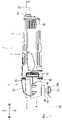
このマルチツール1は、主として、モータハウジング2と、ヘッドハウジング7と、リヤカバー8とから構成されている(図1~4参照)。以下に、これらモータハウジング2と、ヘッドハウジング7と、リヤカバー8とを個別に説明する。 The multi-tool 1 is mainly composed of a
はじめに、モータハウジング2から説明する。このモータハウジング2は、略筒状を成す樹脂製の部材から一体的に(一部材で)構成されている。このモータハウジング2の収容部20(筒状の内部)には、前後方向に延びるようにモータ21が組み付けられている(図5参照)。このモータ21の回転軸22の前側には、遠心ファン23が組み付けられている。また、このモータ21の回転軸22における遠心ファン23の前側には、ベアリング24が組み付けられている。 First, the
また、このモータ21の回転軸22におけるベアリング24の前側には、ベアリング25が組み付けられている。このとき、このベアリング25は、その軸芯である第2軸芯ラインbが、モータ21の回転軸22の軸芯である第1軸芯ラインaに対して偏心した状態(位置ズレした状態)となるように組み付けられている(図6参照)。すなわち、このベアリング25は、モータ21の回転軸22に対して偏心した状態で組み付けられている。 Further, a
一方、このモータ21の回転軸22の後側には、ベアリング26が組み付けられている。この両ベアリング24、26は、モータ21の回転軸22の軸受けを成すものである。そのため、この両ベアリング24、26の各外輪は、モータハウジング2の収容部20に組み付けられている。したがって、このモータ21の回転軸22を滑らかに回転させることができる。 On the other hand, a bearing 26 is assembled on the rear side of the rotating
また、このモータハウジング2のモータ21と遠心ファン23との間における収容部20には、モータ21の回転軸22を貫通した状態で遠心ファン23の周囲を囲む皿状のファンガイド27が組み付けられている。このファンガイド27により、後述するリヤカバー8の吸気口80から取り込まれた外気(冷却エア)の風速を高めることができる。また、このモータハウジング2の左右(左右の側面)には、リヤカバー8の吸気口80から取り込まれた外気を排出可能な排気口28が形成されている。 Further, a dish-
また、このモータハウジング2の後部には、後方に向けて張り出す張出部29が形成されている。この張出部29の前側には、スイッチカバー30を介してスイッチ31が組み付けられている(図3参照)。また、この張出部29の後側には、外部電源が供給される電源コード32に電気的に接続された端子台33が組み付けられている。また、この張出部29の後側には、モータ21の回転軸22を駆動させるコントローラ34が組み付けられている。また、このモータハウジング2の上側には、作業者が指(いずれも図示しない)で操作(スライド操作)可能なスイッチノブ35が組み付けられている。 Further, an overhanging
また、このモータハウジング2の収容部20には、スイッチノブ35の操作に連動してスイッチ31を動作させるスイッチレバー36が組み付けられている。また、この張出部29の後側には、コントローラ34が駆動させるモータ21の回転軸22の回転数を設定可能な変速ダイヤル37が組み付けられている。なお、これらモータ21、スイッチ31、端子台33、変速ダイヤル37は、コントローラ34に対してリード線(図示しない)を介して電気的に接続されている。モータハウジング2は、このように構成されている。 Further, a
次に、ヘッドハウジング7を説明する。このヘッドハウジング7は、主として、ロアヘッドハウジングケース4と、アッパヘッドハウジングカバー5と、スピンドルユニット6とから構成されている。 Next, the
ロアヘッドハウジングケース4は、略逆L字状を成す収容部40を有するように樹脂製の部材から一体的に(一部材で)構成されている。この収容部40の内周面41の内径は、後述するスピンドルユニット6のスピンドル60のベアリング63の外輪63bの外径に対して同等もしくは僅かに大きく設定されている。そのため、後述するように、収容部40にスピンドルユニット6を組み付けたとき、この組み付けたスピンドルユニット6の径方向のガタツキを抑えることができる。 The lower
この収容部40の下側には、後述するスピンドルユニット6のスピンドル60を貫通させる貫通孔42が形成されている。また、この収容部40の下側には、貫通孔42の中心に向けて内周面41より張り出す組付部43が形成されている。また、このロアヘッドハウジングケース4の表面の適宜個所は、エラストマ45によって覆われている。すなわち、このロアヘッドハウジングケース4の表面の適宜個所に対してエラストマ45が二色成形されている。そのため、このロアヘッドハウジングケース4から作業者の手に伝達される震動を抑制できる。ロアヘッドハウジングケース4は、このように構成されている。 A through
また、アッパヘッドハウジングカバー5は、ロアヘッドハウジングケース4の収容部40にスピンドルユニット6を組み付けたとき、この組み付けたスピンドルユニット6を覆うように樹脂製の部材から一体的に(一部材で)構成されている。このアッパヘッドハウジングカバー5の割面50には、下方に向けて突出する略円筒状のリブ51が形成されている。 Further, when the
このリブ51の外周面52における基端側の外径は、ロアヘッドハウジングケース4の収容部40の内周面41の上側の内径に対して同等もしくは僅かに大きく設定されている。そのため、後述するように、ロアヘッドハウジングケース4にアッパヘッドハウジングカバー5を組み付けたとき、このロアヘッドハウジングケース4の内周面41に対してアッパヘッドハウジングカバー5のリブ51の外周面52が嵌合することとなる。したがって、この組み付けたアッパヘッドハウジングカバー5の径方向のガタツキを抑えることができる。 The outer diameter of the base end side of the outer
また、このアッパヘッドハウジングカバー5の割面50には、凹溝54が形成されている。この凹溝54には、シールリング55が組み付けられている。そのため、後述するように、ロアヘッドハウジングケース4にアッパヘッドハウジングカバー5を組み付けて出来上がったスピンドルユニット6において、ロアヘッドハウジングケース4の収容部40に組み付けたスピンドルユニット6に塗布されているグリス(図示しない)が割面44、50から漏れ出すことを防止できる。 Further, a
また、このアッパヘッドハウジングカバー5の表面の適宜個所は、エラストマ56によって覆われている。すなわち、このアッパヘッドハウジングカバー5の表面の適宜個所に対してエラストマ56が二色成形されている。そのため、このアッパヘッドハウジングカバー5から作業者の手に伝達される震動を抑制できる。アッパヘッドハウジングカバー5は、このように構成されている。 Further, an appropriate portion on the surface of the upper
また、スピンドルユニット6は、スピンドル60と、このスピンドル60の上部に基端が組み付けられた(固着された)レバー61と、このスピンドル60の下端側(先端側)に組み付けられたベアリング63と、このスピンドル60の上端側(基端側)に組み付けられたベアリング64とから構成されている。レバー61の先端には、平面視において、左右に対向する押当面62aを有する略コ字状の挟持部62が形成されている。 Further, the
この挟持部62の両押当面62aの間には、上述したモータ21の回転軸22のベアリング25が受け入れられることとなる(図6参照)。また、スピンドル60の下端側には、取付部65が組み付けられて(固着されて)いる。この取付部65の下面には、周方向に沿って複数の凸部65aが形成されている。スピンドルユニット6は、このように構成されている。 The bearing 25 of the
このように構成されているロアヘッドハウジングケース4と、アッパヘッドハウジングカバー5と、スピンドルユニット6とからヘッドハウジング7を組み立てる手順を説明する。まず、ロアヘッドハウジングケース4の収容部40にスピンドルユニット6を組み付ける作業を行う。これにより、ロアヘッドハウジングケース4の貫通孔42からスピンドルユニット6のスピンドル60が下方に向けて突出する。 A procedure for assembling the
次に、このスピンドルユニット6を組み付けたロアヘッドハウジングケース4にアッパヘッドハウジングカバー5を組み付ける作業を行う。この記載が、特許請求の範囲に記載の「前記分割構造は、ロアヘッドハウジングケースと、アッパヘッドハウジングカバーと、を組み付けて成る上下2分割となっており、」に相当する。なお、図5からも明らかなように、ロアヘッドハウジングケース4の割面44とアッパヘッドハウジングカバー5の割面50とを形成する割面ラインcは、モータ21の回転軸22の第1軸芯ラインaより上側に形成されている。 Next, the work of assembling the upper
この組み付け状態において、アッパヘッドハウジングカバー5のリブ51の先端53は、ロアヘッドハウジングケース4に組み付けられたスピンドルユニット6のベアリング63の外輪63bを押し当てている。最後に、ロアヘッドハウジングケース4からアッパヘッドハウジングカバー5に向けて3本のネジ4aを締め付ける作業を行う。このようにしてヘッドハウジング7が組み立てられる。 In this assembled state, the
最後に、リヤカバー8を説明する。このリヤカバー8は、有底の略筒状を成す樹脂製の部材から一体的に(一部材で)構成されている。このリヤカバー8の後側の左右(左右の側面)には、外気を取り込み可能な溝状の吸気口80が複数形成されている。また、このリヤカバー8の後側には、電源コード32を通し可能な通し孔81が形成されている。リヤカバー8は、このように構成されている。 Finally, the
次に、モータハウジング2と、ヘッドハウジング7と、リヤカバー8とから構成されているマルチツール1を組み立てる手順を説明する。まず、モータハウジング2の張出部29を覆うようにリヤカバー8を組み付ける作業を行う。次に、リヤカバー8からモータハウジング2の張出部29に向けてネジ8aを締め付ける作業を行う。次に、モータハウジング2にヘッドハウジング7を組み付ける作業を行う。 Next, a procedure for assembling the
次に、ヘッドハウジング7からモータハウジング2に向けて4本のネジ4bを締め付ける作業を行う。これにより、モータハウジング2の前方にヘッドハウジング7が保持される。最後に、刃66aを有する刃具66をスピンドル60の取付部65とアウタフランジ67との間に挟み込ませ、アウタフランジ67からスピンドル60の取付部65に向けてサラネジ68を締め付ける作業を行う。これにより、スピンドル60の取付部65に刃具66が取り付けられる。 Next, the work of tightening the four
なお、刃具66には、取付部65の凸部65aに対応するように複数の凹穴66bが形成されている。そのため、刃具66をスピンドル60の取付部65とアウタフランジ67との間に挟み込ませるとき、この取付部65の複数の凸部65aを刃具66の複数の凹穴66bに入れ込ませることができる。したがって、刃66aが前を向いた状態で刃具66をスピンドル60の取付部65に取り付けることができる。このようにしてマルチツール1が組み立てられる。 The cutting
続いて、上述したように組み立てられるマルチツール1の動作を説明する。作業者が指でスイッチノブ35を操作すると、コントローラ34を介してモータ21が駆動する。これにより、モータ21の回転軸22が回転する。すると、既に説明したように、ベアリング25はモータ21の回転軸22に対して偏心した状態で組み付けられているため、このベアリング25の外輪25bの外周面25cがスピンドルユニット6のレバー61の対向する押当面62aを交互に押し当てる。 Subsequently, the operation of the
これにより、スピンドル60の軸回りにレバー61が繰り返し揺動するため、これにともない、このスピンドル60の軸回りに刃具66も繰り返し揺動する。したがって、例えば、この刃具66の刃66aの繰り返しの揺動によって石工ボード(図示しない)を切断できる。このとき、モータ21の回転軸22と共に遠心ファン23も回転する。すると、リヤカバー8の吸気口80から外気がリヤカバー8の内部に取り込まれ、この取り込まれた外気がモータハウジング2の排気口28から排出される。 As a result, the
これにより、リヤカバー8の内部およびモータハウジング2の収容部20が外気の通り道となるため(リヤカバー8の内部およびモータハウジング2の収容部20に外気が送り込まれるため)、コントローラ34およびモータ21が冷却されることとなる。したがって、モータ21およびコントローラ34が発熱しても、これらモータ21およびコントローラ34が高温になることを防止できる。 As a result, the inside of the
本発明の第1実施形態に係るマルチツール1は、上述したように構成されている。この構成によれば、ヘッドハウジング7は、樹脂製の部材から構成されている。そのため、従来技術とは異なり、マルチツール1の重量を軽くできる。したがって、マルチツール1の作業時の操作性を向上させることができる。 The
また、この構成によれば、ヘッドハウジング7は、ロアヘッドハウジングケース4と、アッパヘッドハウジングカバー5とを組み付けて成る2分割構造となっている。そのため、ヘッドハウジング7の内部にスピンドルユニット6を組み付ける作業を行う時、このヘッドハウジング7をロアヘッドハウジングケース4とアッパヘッドハウジングカバー5とに分解した状態で、この組み付ける作業を実施できる。したがって、ヘッドハウジング7を分解できない場合と比較すると、スピンドルユニット6を内部に組み付ける作業の作業性を高めることができる。すなわち、ヘッドハウジング7の内部にスピンドルユニット6を簡便に組み付けることができる。 Further, according to this configuration, the
また、この構成によれば、ロアヘッドハウジングケース4の割面44とアッパヘッドハウジングカバー5の割面50とを形成する割面ラインcは、モータ21の回転軸22の第1軸芯ラインaより上側に形成されている。そのため、スピンドルユニット6のスピンドル60の軸回りに刃具66が繰り返し揺動することによってロアヘッドハウジングケース4に対して捩じり力が作用しても、この捩じり力に対する剛性をロアヘッドハウジングケース4に持たせることができる。 Further, according to this configuration, the split surface line c forming the split surface 44 of the lower
また、この構成によれば、ヘッドハウジング7の内部(ロアヘッドハウジングケース4の収容部40)にスピンドルユニット6を組み付けた状態において、アッパヘッドハウジングカバー5のリブ51の先端53は、ロアヘッドハウジングケース4に組み付けられたスピンドルユニット6のベアリング63の外輪63bを押し当てている。そのため、この組み付け状態におけるベアリング63の軸方向へのガタツキを防止できる。 Further, according to this configuration, in a state where the
(第2実施形態)
次に、本発明の第2実施形態を図7を用いて説明する。この第2実施形態に係るマルチツール101は、第1実施形態に係るマルチツール1と比較すると、モータハウジング2とヘッドハウジング7との構造が相違した形態である。なお、以下の説明にあたって、第1実施形態で説明した部材と同一または均等な構成の部材には、図面において、同一符号を付すことで重複する説明は省略することとする。(Second Embodiment)
Next, the second embodiment of the present invention will be described with reference to FIG. 7. The
このマルチツール101は、主として、モータハウジング2と、ヘッドハウジング7ととから構成されている(図7参照)。このマルチツール101のモータハウジング2は、第1実施形態のリヤカバー8も兼ねるものとなっており、有底の略筒状を成す樹脂製の部材から構成されている。なお、このマルチツール101のモータハウジング2は、図7からも明らかなように、上下に対を成す半割ハウジング2a、2bをネジ(図示しない)で組み付けて成る2分割構造となっている。 The
また、このマルチツール101のヘッドハウジング7は、第1実施形態のロアヘッドハウジングケース4とアッパヘッドハウジングカバー5とが一体的に(一部材で)構成されたものである。なお、このマルチツール101の他の構造は、マルチツール1の構造と同一となっている。 Further, the
本発明の第2実施形態に係るマルチツール101は、上述したように構成されている。この構成によれば、マルチツール1と同様の作用効果を得ることができる。また、マルチツール101のヘッドハウジング7は、一体的に構成されている。そのため、ヘッドハウジング7が分割構造の場合と比較すると、ヘッドハウジング7そのものの強度を高めることができる。また、マルチツール101のモータハウジング2は、上下に対を成す半割ハウジング2a、2bをネジで組み付けて成る2分割構造となっている。そのため、モータハウジング2を上下に2分割した状態(半割りした状態)で各種部品(例えば、モータ21、遠心ファン23、スイッチ31等)をモータハウジング2の収容部20に組み付けることができる。したがって、この組み付けの作業性を高めることができる。 The
上述した内容は、あくまでも本発明の一実施の形態に関するものであって、本発明が上記内容に限定されることを意味するものではない。 The above-mentioned contents are merely related to one embodiment of the present invention, and do not mean that the present invention is limited to the above-mentioned contents.
各実施形態では、『電動工具』が『マルチツール1、101』である例を説明した。しかし、これに限定されるものでなく、『電動工具』が『アングルタイプの電動工具』であれば、どのようなものでも構わない。 In each embodiment, an example in which the "power tool" is "
また、第1実施形態では、ヘッドハウジング7は、上下2分割構造である例を説明した。しかし、これに限定されるものでなく、ヘッドハウジング7は、前後2分割構造または左右2分割構造であっても構わない。もちろん、ヘッドハウジング7は、樹脂製の部材から一体的に(一部材で)構成されていても構わない。 Further, in the first embodiment, an example in which the
また、第1実施形態では、モータハウジング2は、略筒状を成す樹脂製の部材から一体的に(一部材で)構成されている例を説明した。しかし、これに限定されるものでなく、モータハウジング2は、略筒状を成す樹脂製の部材から縦割り(左右割り)または横割り(上下割り)の半割に(半割りの二部材で)構成されていても構わない。その場合、半割の二部材を留めるネジが必要となる。 Further, in the first embodiment, an example has been described in which the
また、第2実施形態では、マルチツール101のモータハウジング2は、上下に対を成す半割ハウジング2a、2bをネジで組み付けて成る2分割構造となっている例を説明した。しかし、これに限定されるものでなく、マルチツール101のモータハウジング2は、左右に対を成す半割ハウジング2a、2bをネジで組み付けて成る2分割構造となっていても構わない。 Further, in the second embodiment, an example has been described in which the
1 マルチツール(電動工具、第1実施形態)
2 モータハウジング
2a 半割ハウジング
2b 半割ハウジング
4 ロアヘッドハウジングケース
4a ネジ
4b ネジ
5 アッパヘッドハウジングカバー
6 スピンドルユニット
7 ヘッドハウジング
8 リヤカバー
8a ネジ
20 収容部
21 モータ
22 回転軸
23 遠心ファン
24 ベアリング
25 ベアリング
25a 内輪
25b 外輪
25c 外周面
26 ベアリング
27 ファンガイド
28 排気口
29 張出部
30 スイッチカバー
31 スイッチ
32 電源コード
33 端子台
34 コントローラ
35 スイッチノブ
36 スイッチレバー
37 変速ダイヤル
40 収容部
41 内周面
42 貫通孔
43 組付部
44 割面
45 エラストマ
50 割面
51 リブ
52 外周面
53 先端
54 凹溝
55 シールリング
56 エラストマ
60 スピンドル(出力軸)
61 レバー
62 挟持部
62a 押当面
63 ベアリング
63a 内輪
63b 外輪
64 ベアリング
65 取付部
65a 凸部
66 刃具
66a 刃
66b 凹穴
67 アウタフランジ
68 サラネジ
80 吸気口
81 通し孔
101 マルチツール(電動工具、第2実施形態)
a 第1軸芯ライン(モータ)
b 第2軸芯ライン(ベアリング)
c 割面ライン
1 Multi-tool (power tool, 1st embodiment)
2
61
a 1st axis core line (motor)
b 2nd shaft core line (bearing)
c split plane line
Claims (5)
Translated fromJapanese前記モータを収容する筒状の樹脂製のモータハウジングと、
前記筒状のモータハウジングにネジ止めされる樹脂製のロアヘッドハウジングケースと、
前記ロアヘッドハウジングケースにネジ止めされる樹脂製のアッパヘッドハウジングカバーと、
前記回転軸の後部を支持し、前記モータハウジングに保持されるモータ後ベアリングと、
前記回転軸の前部を支持し、前記ロアヘッドハウジングケースに保持されるモータ前ベアリングと、
前記回転軸により揺動され、前記ロアヘッドハウジングケース及び前記アッパヘッドハウジングカバーに収容されるレバーと、
前記レバーに固定されるスピンドルと、
前記スピンドルの上部を支持し、前記アッパヘッドハウジングカバーに保持されるスピンドル上ベアリングと、
前記スピンドルの下部を支持し、前記ロアヘッドハウジングケースに保持されるスピンドル下ベアリングと、を有するマルチツール。A motor with a rotating shaft and
A cylindrical resin motor housing that houses the motor,
A resin lower head housing case screwed to the tubular motor housing,
The resin upper head housing cover screwed to the lower head housing case,
A motor rear bearing that supports the rear part of the rotating shaft and is held in the motor housing,
A motor front bearing that supports the front part of the rotating shaft and is held in the lower head housing case, and
A lever that is swung by the rotating shaft and is housed in the lower head housing case and the upper head housing cover.
The spindle fixed to the lever and
A bearing on the spindle that supports the upper part of the spindle and is held by the upper head housing cover,
A multi-tool with a under-spindle bearing that supports the lower part of the spindle and is held in the lower head housing case.
前記レバーの下方側に、前記ロアヘッドハウジングケースが配置されている請求項1記載のマルチツール。The upper head housing cover is arranged on the upper side of the lever.
The multi-tool according to claim 1, wherein the lower head housing case is arranged on the lower side of the lever.
前記偏心ベアリングの上方側に、前記アッパヘッドハウジングカバーが配置されており、
前記偏心ベアリングの下方側に、前記ロアヘッドハウジングケースが配置されている請求項2記載のマルチツール。It has an eccentric bearing that is rotated by the rotating shaft and eccentric from the axis of the rotating shaft.
The upper head housing cover is arranged on the upper side of the eccentric bearing.
The multi-tool according to claim 2, wherein the lower head housing case is arranged on the lower side of the eccentric bearing.
前記ロアヘッドハウジングケースから下方に突出する前記スピンドルの先端側は、前記スピンドル下ベアリングを介して前記ロアヘッドハウジングケースに組み付けられており、
前記組み付け状態において、前記リブの先端面の全ては、前記ロアヘッドハウジングケースに組み付けられた前記スピンドル下ベアリングの外輪を押し当てている請求項1~3のいずれか1項に記載のマルチツール。The upper head housing cover is formed with ribs that can be fitted to the lower head housing case.
The tip end side of thespindle protruding downward from the lower head housing case is assembled to the lower head housing case via thebearing under the spindle.
The multi-tool according to any one of claims 1 to 3, wherein in the assembled state, all of the tip surfaces of the ribs are pressed against the outer ring of thebearing under the spindle assembled to the lower head housing case.
The multi-tool according to any one of claims 1 to 4, wherein a seal ring is interposed between the lower head housing case and the upper head housing cover.
Priority Applications (4)
| Application Number | Priority Date | Filing Date | Title |
|---|---|---|---|
| JP2018062172AJP7096032B2 (en) | 2018-03-28 | 2018-03-28 | Multi tool |
| US16/256,516US11045939B2 (en) | 2018-03-28 | 2019-01-24 | Power tool |
| CN201910091888.7ACN110315482B (en) | 2018-03-28 | 2019-01-30 | Electric tool |
| DE102019104639.4ADE102019104639A1 (en) | 2018-03-28 | 2019-02-25 | power tool |
Applications Claiming Priority (1)
| Application Number | Priority Date | Filing Date | Title |
|---|---|---|---|
| JP2018062172AJP7096032B2 (en) | 2018-03-28 | 2018-03-28 | Multi tool |
Publications (2)
| Publication Number | Publication Date |
|---|---|
| JP2019171513A JP2019171513A (en) | 2019-10-10 |
| JP7096032B2true JP7096032B2 (en) | 2022-07-05 |
Family
ID=67909782
Family Applications (1)
| Application Number | Title | Priority Date | Filing Date |
|---|---|---|---|
| JP2018062172AActiveJP7096032B2 (en) | 2018-03-28 | 2018-03-28 | Multi tool |
Country Status (4)
| Country | Link |
|---|---|
| US (1) | US11045939B2 (en) |
| JP (1) | JP7096032B2 (en) |
| CN (1) | CN110315482B (en) |
| DE (1) | DE102019104639A1 (en) |
Cited By (1)
| Publication number | Priority date | Publication date | Assignee | Title |
|---|---|---|---|---|
| WO2025005244A1 (en)* | 2023-06-30 | 2025-01-02 | 工機ホールディングス株式会社 | Housing unit, working machine, and method for manufacturing housing unit |
Families Citing this family (10)
| Publication number | Priority date | Publication date | Assignee | Title |
|---|---|---|---|---|
| US11396078B2 (en)* | 2019-06-10 | 2022-07-26 | Makita Corporation | Grinder |
| US11660690B2 (en) | 2019-11-28 | 2023-05-30 | Makita Corporation | Power tool |
| US11590593B2 (en) | 2019-11-28 | 2023-02-28 | Makita Corporation | Power tool |
| JP7422538B2 (en) | 2019-12-26 | 2024-01-26 | 株式会社マキタ | Work tools |
| JP7330914B2 (en) | 2020-02-13 | 2023-08-22 | 株式会社マキタ | vibration tool |
| US20210362317A1 (en)* | 2020-05-21 | 2021-11-25 | Nanjing Chervon Industry Co., Ltd. | Electric tool |
| DE102022206703A1 (en) | 2022-06-30 | 2024-01-04 | Robert Bosch Gesellschaft mit beschränkter Haftung | Machine tool device, machine tool and machine tool system |
| EP4327980B1 (en)* | 2022-08-26 | 2025-06-04 | Nanjing Chervon Industry Co., Ltd. | Power tool |
| JPWO2024117162A1 (en)* | 2022-11-30 | 2024-06-06 | ||
| US20240383120A1 (en)* | 2023-05-16 | 2024-11-21 | Black & Decker Inc. | Oscillating tool |
Citations (9)
| Publication number | Priority date | Publication date | Assignee | Title |
|---|---|---|---|---|
| JP2007185716A (en) | 2006-01-11 | 2007-07-26 | Hitachi Koki Co Ltd | Electric tool and assembling method thereof |
| JP2008178979A (en) | 2008-04-22 | 2008-08-07 | Hitachi Koki Co Ltd | Electric tool |
| US20110067894A1 (en) | 2009-09-24 | 2011-03-24 | Credo Technology Corporation | Counterbalance for eccentric shafts |
| WO2012045679A2 (en) | 2010-10-04 | 2012-04-12 | Robert Bosch Gmbh | Oscillating hand-held power tool |
| JP2014050920A (en) | 2012-09-07 | 2014-03-20 | Makita Corp | Electric device |
| JP2015027716A (en) | 2013-07-30 | 2015-02-12 | 日立工機株式会社 | Electric tool |
| JP2016032844A (en) | 2014-07-31 | 2016-03-10 | 日立工機株式会社 | Electric tool |
| US20160271711A1 (en) | 2013-11-29 | 2016-09-22 | Positec Power Tools (Suzhou) Co., Ltd | Oscillating power tool |
| US20170106490A1 (en) | 2015-10-14 | 2017-04-20 | Black & Decker Inc. | Handheld grinder with brushless electric motor |
Family Cites Families (99)
| Publication number | Priority date | Publication date | Assignee | Title |
|---|---|---|---|---|
| US78652A (en) | 1868-06-09 | Improvement in braces foe bits | ||
| DE1217174B (en) | 1963-10-11 | 1966-05-18 | Gildemeister Werkzeugmasch | Chuck for external machining of hollow bodies with irregular internal shapes, e.g. B. of pistons for internal combustion engines |
| US3622170A (en) | 1968-05-20 | 1971-11-23 | Kearney & Trecker Corp | Tool-locking mechanism |
| US3998467A (en) | 1975-08-19 | 1976-12-21 | Tony Petkovich | Tool chuck for a drill press |
| US4205572A (en) | 1978-08-29 | 1980-06-03 | Weiner Robert I | Saw blade retainer and kickback clutch assembly |
| US4237659A (en) | 1979-03-22 | 1980-12-09 | Dynabrade, Inc. | Quick change adapter for mounting rotatable grinding elements |
| JPS58150012A (en) | 1982-03-02 | 1983-09-06 | Nissan Motor Co Ltd | Internal combustion engine valve equipment |
| EP0152564B1 (en) | 1984-02-18 | 1989-08-23 | C. & E. FEIN GmbH & Co. | Tool mounting |
| US4575937A (en) | 1984-10-22 | 1986-03-18 | Mccullough Timothy J | Depth control gauge for meat trimming knife |
| JPS62181901A (en) | 1986-02-05 | 1987-08-10 | Sanshin Giken:Kk | Quick release equipment for hub for bicycle |
| US5031361A (en) | 1986-04-03 | 1991-07-16 | Mackay Joseph H Jun | Disposable finishing article having integral mounting hub including improved metal pressure cap |
| US4747607A (en) | 1987-03-30 | 1988-05-31 | James Emter | Lobed chuck for saw regrinding |
| JPS63173802U (en) | 1987-05-02 | 1988-11-11 | ||
| DE3741484C1 (en) | 1987-12-08 | 1989-08-24 | Fein C & E | Hand machine tool with automatic locking of the work spindle |
| EP0495181B1 (en) | 1991-01-16 | 1994-04-13 | C. & E. FEIN GmbH & Co. | Grinding power tool with quick coupling means |
| DE59200319D1 (en) | 1991-07-05 | 1994-09-01 | Fein C & E | Portable machine tool. |
| FI91136C (en) | 1992-07-03 | 1994-05-25 | Kauko Rautio | Round blade mounting system |
| DE4236964A1 (en) | 1992-11-02 | 1994-05-05 | Hilti Ag | Disc-shaped tool for angle grinders |
| DE4336620C2 (en) | 1993-10-27 | 1997-07-03 | Fein C & E | Power tool with a clamping device that can only be operated when the engine is switched off |
| US5575071A (en) | 1994-01-19 | 1996-11-19 | Porter-Cable Corporation | Toolless quickchange blade clamp for reciprocating saws |
| US5658193A (en)* | 1994-04-18 | 1997-08-19 | Wahl Clipper Corporation | Reciprocating hand tool with multiple attachments |
| MX9705952A (en) | 1995-02-03 | 1998-02-28 | Cme Blasting & Mining Equip | Grinding cup and holder device. |
| DE19509539A1 (en) | 1995-03-16 | 1996-09-19 | Bosch Gmbh Robert | Jigsaw |
| US5573255A (en) | 1995-05-05 | 1996-11-12 | Power Tool Holders, Inc. | Quick release chuck device for saw blades |
| DE29605728U1 (en) | 1996-03-28 | 1996-09-05 | C. & E. Fein Gmbh & Co, 70176 Stuttgart | Saw blade |
| JPH09267251A (en)* | 1996-04-02 | 1997-10-14 | S P Air Kk | Grinding device |
| US5759093A (en)* | 1996-08-29 | 1998-06-02 | Rodriguez; John | Electric oscillating abrasive file |
| US6142858A (en) | 1997-11-10 | 2000-11-07 | 3M Innovative Properties Company | Backup pad for abrasive articles |
| JP3676609B2 (en) | 1998-09-29 | 2005-07-27 | 株式会社マキタ | Mounting structure of hanging tool in electric power tool |
| US6244943B1 (en)* | 1998-12-30 | 2001-06-12 | Guther Bohler Gmbh | Surface-processing apparatus |
| JP3995895B2 (en) | 2000-05-16 | 2007-10-24 | 株式会社マキタ | Blade mounting device for reciprocating cutting tool |
| SE516524C2 (en) | 2000-05-18 | 2002-01-22 | Sandvik Ab | Utilities Connection |
| DE10030586A1 (en) | 2000-06-21 | 2002-01-10 | Bruno Schmitz Schleifmittelwer | Tool |
| DE10039739A1 (en) | 2000-08-16 | 2002-02-28 | C & E Fein Gmbh & Co Kg | Power tool with quick release device |
| DE10040330A1 (en) | 2000-08-17 | 2002-02-28 | Hilti Ag | Power tool with clamping device |
| DE10059712A1 (en) | 2000-12-01 | 2002-06-20 | Bosch Gmbh Robert | Hand tool |
| US6945862B2 (en) | 2000-12-07 | 2005-09-20 | C. & E. Fein Gmbh | Power tool having a receptacle for securing a tool |
| DE10061559A1 (en) | 2000-12-07 | 2002-06-13 | C & E Fein Gmbh & Co Kg | Holder for attaching a tool to a drive shaft and adapter for this |
| US6735876B2 (en) | 2001-03-01 | 2004-05-18 | Makita Corporation | Blade clamps suitable for reciprocating power tools |
| DE10124971B4 (en) | 2001-05-21 | 2013-06-20 | Hilti Aktiengesellschaft | Quick clamping device for a circular saw |
| US6949110B2 (en) | 2001-06-22 | 2005-09-27 | Microaire Surgical Instruments, Inc. | Connector assembly for a surgical tool |
| DE20117159U1 (en) | 2001-10-16 | 2002-02-14 | C. & E. Fein GmbH & Co KG, 70176 Stuttgart | Machine tool with mounting flange |
| DE10161930A1 (en) | 2001-12-17 | 2003-06-18 | Hilti Ag | Tool holder for a grinder |
| DE60305539T2 (en)* | 2002-01-10 | 2007-05-03 | Black & Decker Inc., Newark | gearbox |
| JP2004351538A (en) | 2003-05-27 | 2004-12-16 | Matsushita Electric Works Ltd | Portable electric tool with hook |
| DE10352291A1 (en) | 2003-11-08 | 2005-06-02 | Robert Bosch Gmbh | Tool receiving device for an insert tool with an at least substantially disc-shaped hub |
| DE10361810A1 (en) | 2003-12-30 | 2005-07-28 | Robert Bosch Gmbh | Hand tool with clamping device |
| US7871080B2 (en) | 2004-01-16 | 2011-01-18 | Robert Bosch Gmbh | Tool-less blade clamping apparatus for a reciprocating tool |
| DE102004020982A1 (en) | 2004-04-23 | 2005-11-17 | C. & E. Fein Gmbh | Powered hand tool with clamping device for a tool |
| US7789737B2 (en) | 2004-07-08 | 2010-09-07 | Metabowerke Gmbh | Rapid locking device |
| US7497860B2 (en)* | 2004-07-09 | 2009-03-03 | Stryker Corporation | Surgical sagittal saw including a handpiece and a removable blade assembly, the blade assembly including a guide bar, a blade head capable of oscillatory movement and a drive rod for actuating the blade head |
| AT8511U1 (en) | 2005-04-05 | 2006-09-15 | Ceratizit Austria Gmbh | TOOL CONSTRUCTION |
| DE102005031802A1 (en) | 2005-07-07 | 2007-01-11 | Keppler, Karl | Tool receiver for machine tool has at least one fixing element to lock fork elements in tool receiving position |
| DE102005047402B4 (en) | 2005-10-04 | 2016-02-11 | Metabowerke Gmbh | Power tool with a tool holder and tool for this purpose |
| DE102005047400B3 (en) | 2005-10-04 | 2006-12-28 | Metabowerke Gmbh | Electric driven tool device has a manually operatable switch, which can be adjusted between on-position, off-position and third position, in which device can be operated for locking or releasing tool only in release direction |
| DE502005003376D1 (en) | 2005-11-28 | 2008-04-30 | Metabowerke Gmbh | Tool device with quick clamping device |
| JP4708989B2 (en)* | 2005-12-07 | 2011-06-22 | 株式会社マキタ | Grinder |
| DE102006021969A1 (en) | 2006-05-04 | 2007-11-08 | C. & E. Fein Gmbh | oscillatory |
| CN200995304Y (en) | 2007-01-16 | 2007-12-26 | 南京德朔实业有限公司 | Fast saw bit clamping device |
| JP4964642B2 (en) | 2007-03-27 | 2012-07-04 | 株式会社マキタ | Rotating blade fixing device |
| DE102007036786A1 (en) | 2007-04-19 | 2008-10-23 | Robert Bosch Gmbh | Adapter for a motor-driven machine tool with rotatably driven tool |
| DE102007035045A1 (en) | 2007-07-19 | 2009-01-29 | C. & E. Fein Gmbh | Powered hand tool |
| DE202008001759U1 (en) | 2008-02-01 | 2009-06-04 | C. & E. Fein Gmbh | Oscillating drivable machine tool |
| US8181973B2 (en) | 2008-05-05 | 2012-05-22 | Robert Bosch Gmbh | Clamping apparatus for a reciprocating tool |
| DE202009001440U1 (en) | 2009-01-30 | 2010-07-01 | C. & E. Fein Gmbh | Powered hand tool with clamping device for a tool |
| DE102009014970A1 (en) | 2009-03-18 | 2010-09-23 | C. & E. Fein Gmbh | Oscillation tool with vibration damping |
| JP2011079113A (en) | 2009-10-09 | 2011-04-21 | Tenryu Saw Mfg Co Ltd | Device for mounting disc-shaped rotary tool |
| JP5510887B2 (en)* | 2010-01-13 | 2014-06-04 | 日立工機株式会社 | Electric tool |
| JP5456556B2 (en) | 2010-04-23 | 2014-04-02 | 株式会社マキタ | Work tools |
| US20110266759A1 (en) | 2010-04-29 | 2011-11-03 | Black & Decker Inc. | Oscillating tool |
| US20130193655A1 (en) | 2010-04-29 | 2013-08-01 | Black & Decker Inc. | Oscillating Tool Adapter |
| CN202114710U (en) | 2010-06-25 | 2012-01-18 | 南京德朔实业有限公司 | Workpiece capable of being adaptive with various shaft ends |
| CN102294682B (en) | 2010-06-25 | 2014-06-11 | 南京德朔实业有限公司 | Working component capable of being fit with various shaft ends |
| DE102010031329A1 (en) | 2010-07-14 | 2012-02-02 | Robert Bosch Gmbh | Tool holder for a machine tool |
| CN201728642U (en) | 2010-08-05 | 2011-02-02 | 宁波捷美进出口有限公司 | Tool head-mounting hole structure |
| DE102010046629A1 (en) | 2010-09-17 | 2012-03-22 | C. & E. Fein Gmbh | hand tool |
| JP5518679B2 (en)* | 2010-11-16 | 2014-06-11 | 株式会社マキタ | Rotating tool |
| CN102528768B (en) | 2010-12-07 | 2014-10-15 | 南京德朔实业有限公司 | Power tool |
| DE102011005021A1 (en) | 2011-03-03 | 2012-09-06 | Robert Bosch Gmbh | Oscillation tool clamping apparatus for use in portable machine tool utilized for machining workpiece on tool holder of drive unit, has head supported along movement axis that is different from axis running parallel to axial direction |
| DE102011005818A1 (en) | 2011-03-18 | 2012-09-20 | Robert Bosch Gmbh | Machine tools fixture |
| WO2012155253A1 (en)* | 2011-05-18 | 2012-11-22 | Crystal Glass Canada Ltd. | Reciprocating power tool |
| DE202011110131U1 (en) | 2011-06-06 | 2013-02-11 | Robert Bosch Gmbh | Hand machine tool fixture |
| DE102011081661B4 (en) | 2011-08-26 | 2023-11-30 | Robert Bosch Gmbh | Switchable gearbox for a hand-held machine tool |
| EP2762276B1 (en) | 2011-09-29 | 2016-07-27 | Positec Power Tools (Suzhou) Co., Ltd | Multifunctional machine |
| JP5775796B2 (en)* | 2011-11-08 | 2015-09-09 | 株式会社マキタ | Electric tool |
| JP5746645B2 (en)* | 2012-02-03 | 2015-07-08 | 株式会社マキタ | Work tools |
| JP2014131824A (en) | 2013-01-07 | 2014-07-17 | Makita Corp | Work tool |
| US9108255B2 (en) | 2013-01-28 | 2015-08-18 | Gison Machinery Co., Ltd. | Fast knockdown cutting tool assembly |
| US9555554B2 (en) | 2013-05-06 | 2017-01-31 | Milwaukee Electric Tool Corporation | Oscillating multi-tool system |
| US9221156B2 (en)* | 2013-05-15 | 2015-12-29 | Snap-On Incorporated | Motorized hand tool apparatus and assembly method |
| DE202013006920U1 (en) | 2013-08-01 | 2014-11-03 | C. & E. Fein Gmbh | tooling |
| DE202013006900U1 (en) | 2013-08-01 | 2014-11-03 | C. & E. Fein Gmbh | machine tool |
| NO2884309T3 (en) | 2013-08-01 | 2018-09-08 | ||
| DE102014103048B4 (en) | 2014-03-07 | 2016-11-17 | C. & E. Fein Gmbh | Electric tool comprising a component for producing a positive rivet connection of a tool |
| JP6646373B2 (en)* | 2015-07-23 | 2020-02-14 | 京セラインダストリアルツールズ株式会社 | Hand-held power tool |
| CN106475974B (en)* | 2015-08-31 | 2021-06-11 | 苏州宝时得电动工具有限公司 | Hand-held tool and clamping device thereof |
| US20180319001A1 (en)* | 2016-01-14 | 2018-11-08 | Positec Power Tools (Suzhou) Co., Ltd. | Power Tool |
| JP6703417B2 (en)* | 2016-02-19 | 2020-06-03 | 株式会社マキタ | Work tools |
| DE102017116823A1 (en)* | 2017-07-25 | 2019-01-31 | C. & E. Fein Gmbh | Oscillating powered machine tool |
- 2018
- 2018-03-28JPJP2018062172Apatent/JP7096032B2/enactiveActive
- 2019
- 2019-01-24USUS16/256,516patent/US11045939B2/enactiveActive
- 2019-01-30CNCN201910091888.7Apatent/CN110315482B/enactiveActive
- 2019-02-25DEDE102019104639.4Apatent/DE102019104639A1/enactivePending
Patent Citations (9)
| Publication number | Priority date | Publication date | Assignee | Title |
|---|---|---|---|---|
| JP2007185716A (en) | 2006-01-11 | 2007-07-26 | Hitachi Koki Co Ltd | Electric tool and assembling method thereof |
| JP2008178979A (en) | 2008-04-22 | 2008-08-07 | Hitachi Koki Co Ltd | Electric tool |
| US20110067894A1 (en) | 2009-09-24 | 2011-03-24 | Credo Technology Corporation | Counterbalance for eccentric shafts |
| WO2012045679A2 (en) | 2010-10-04 | 2012-04-12 | Robert Bosch Gmbh | Oscillating hand-held power tool |
| JP2014050920A (en) | 2012-09-07 | 2014-03-20 | Makita Corp | Electric device |
| JP2015027716A (en) | 2013-07-30 | 2015-02-12 | 日立工機株式会社 | Electric tool |
| US20160271711A1 (en) | 2013-11-29 | 2016-09-22 | Positec Power Tools (Suzhou) Co., Ltd | Oscillating power tool |
| JP2016032844A (en) | 2014-07-31 | 2016-03-10 | 日立工機株式会社 | Electric tool |
| US20170106490A1 (en) | 2015-10-14 | 2017-04-20 | Black & Decker Inc. | Handheld grinder with brushless electric motor |
Cited By (1)
| Publication number | Priority date | Publication date | Assignee | Title |
|---|---|---|---|---|
| WO2025005244A1 (en)* | 2023-06-30 | 2025-01-02 | 工機ホールディングス株式会社 | Housing unit, working machine, and method for manufacturing housing unit |
Also Published As
| Publication number | Publication date |
|---|---|
| US11045939B2 (en) | 2021-06-29 |
| JP2019171513A (en) | 2019-10-10 |
| CN110315482A (en) | 2019-10-11 |
| DE102019104639A1 (en) | 2019-10-02 |
| CN110315482B (en) | 2023-02-24 |
| US20190299387A1 (en) | 2019-10-03 |
Similar Documents
| Publication | Publication Date | Title |
|---|---|---|
| JP7096032B2 (en) | Multi tool | |
| JP6703417B2 (en) | Work tools | |
| JP2006297536A (en) | Rotating tool | |
| US11999045B2 (en) | Work tool | |
| JP7039209B2 (en) | Polisher | |
| JP2017136675A (en) | Power tool | |
| WO2015155912A1 (en) | Electrically driven tool | |
| JP2022084181A (en) | Work machine | |
| JP6266304B2 (en) | Reciprocating cutting tool | |
| CN115842435A (en) | Hand-held electric tool and motor assembly for electric tool | |
| US4580460A (en) | Bevel gear backlash adjusting mechanism | |
| WO2018180084A1 (en) | Electric tool | |
| JP2022017127A (en) | Working tool | |
| JP7705026B2 (en) | Work Machine | |
| JP2007196409A (en) | Electric cutting tool | |
| JP7070337B2 (en) | Electrical equipment | |
| JP7040371B2 (en) | Electric tool | |
| JP4934717B2 (en) | Rotating tool | |
| WO2017064901A1 (en) | Electric tool | |
| US20230278186A1 (en) | Self-Aligning Bearing Support Assembly | |
| US20230264336A1 (en) | Working device | |
| JP7286444B2 (en) | portable cutting machine | |
| JP7338535B2 (en) | work machine | |
| GB2417456A (en) | Electric machine tool housing | |
| JP2021000701A (en) | Power tool |
Legal Events
| Date | Code | Title | Description |
|---|---|---|---|
| A621 | Written request for application examination | Free format text:JAPANESE INTERMEDIATE CODE: A621 Effective date:20201211 | |
| A977 | Report on retrieval | Free format text:JAPANESE INTERMEDIATE CODE: A971007 Effective date:20210831 | |
| A131 | Notification of reasons for refusal | Free format text:JAPANESE INTERMEDIATE CODE: A131 Effective date:20210907 | |
| A521 | Request for written amendment filed | Free format text:JAPANESE INTERMEDIATE CODE: A523 Effective date:20211026 | |
| A131 | Notification of reasons for refusal | Free format text:JAPANESE INTERMEDIATE CODE: A131 Effective date:20220315 | |
| A521 | Request for written amendment filed | Free format text:JAPANESE INTERMEDIATE CODE: A523 Effective date:20220328 | |
| TRDD | Decision of grant or rejection written | ||
| A01 | Written decision to grant a patent or to grant a registration (utility model) | Free format text:JAPANESE INTERMEDIATE CODE: A01 Effective date:20220621 | |
| A61 | First payment of annual fees (during grant procedure) | Free format text:JAPANESE INTERMEDIATE CODE: A61 Effective date:20220623 | |
| R150 | Certificate of patent or registration of utility model | Ref document number:7096032 Country of ref document:JP Free format text:JAPANESE INTERMEDIATE CODE: R150 | |
| R250 | Receipt of annual fees | Free format text:JAPANESE INTERMEDIATE CODE: R250 |