Movatterモバイル変換


[0]ホーム

URL:


JP7096029B2 - Lens unit for ophthalmic appliances - Google Patents

Lens unit for ophthalmic appliances
Download PDF

Info

Publication number
JP7096029B2
JP7096029B2JP2018060263AJP2018060263AJP7096029B2JP 7096029 B2JP7096029 B2JP 7096029B2JP 2018060263 AJP2018060263 AJP 2018060263AJP 2018060263 AJP2018060263 AJP 2018060263AJP 7096029 B2JP7096029 B2JP 7096029B2
Authority
JP
Japan
Prior art keywords
lens
ring
storage cylinder
snap
peripheral surface
Prior art date
Legal status (The legal status is an assumption and is not a legal conclusion. Google has not performed a legal analysis and makes no representation as to the accuracy of the status listed.)
Active
Application number
JP2018060263A
Other languages
Japanese (ja)
Other versions
JP2019170500A (en
Inventor
浩樹 櫻田
陽紀 奥田
Current Assignee (The listed assignees may be inaccurate. Google has not performed a legal analysis and makes no representation or warranty as to the accuracy of the list.)
Topcon Corp
Original Assignee
Topcon Corp
Priority date (The priority date is an assumption and is not a legal conclusion. Google has not performed a legal analysis and makes no representation as to the accuracy of the date listed.)
Filing date
Publication date
Application filed by Topcon CorpfiledCriticalTopcon Corp
Priority to JP2018060263ApriorityCriticalpatent/JP7096029B2/en
Publication of JP2019170500ApublicationCriticalpatent/JP2019170500A/en
Application grantedgrantedCritical
Publication of JP7096029B2publicationCriticalpatent/JP7096029B2/en
Activelegal-statusCriticalCurrent
Anticipated expirationlegal-statusCritical

Links

Images

Landscapes

Description

Translated fromJapanese

本発明は、光学系を備える眼科装置のレンズユニットに関する。 The present invention relates to a lens unit of an ophthalmic apparatus including an optical system.

眼科装置として、光干渉断層計、走査型レーザ顕微鏡、スリットランプ、レフラクトメータ、ケラトメータ、スペキュラーマイクロスコープ、眼圧計、及びウェーブフロントアナライザ等が知られている。これらの眼科装置には、被検眼の照明或いは撮影などに用いられる各種の光学系が1以上設けられている(特許文献1参照)。この光学系には、1以上のレンズと、この1以上のレンズを収納するレンズ収納筒(セル、ケース、鏡胴、及び筐体ともいう)とを備えるレンズユニットが設けられている。そして、このレンズユニットを組み立てる際には、作業者の手作業によって、レンズをレンズ収納筒内に接着剤で固定するのが通常である。 As an ophthalmic apparatus, an optical coherence tomography, a scanning laser microscope, a slit lamp, a reflex meter, a keratometer, a specular microscope, a tonometer, a wavefront analyzer and the like are known. These ophthalmic devices are provided with one or more various optical systems used for lighting or photographing the eye to be inspected (see Patent Document 1). The optical system is provided with a lens unit including one or more lenses and a lens storage cylinder (also referred to as a cell, a case, a lens barrel, and a housing) for accommodating the one or more lenses. Then, when assembling this lens unit, it is usual that the lens is manually fixed in the lens storage cylinder by an operator with an adhesive.

特開2013-248376号公報Japanese Unexamined Patent Publication No. 2013-248376

ところで、レンズをレンズ収納筒内に接着剤で固定すると、この接着剤からアウトガスが発生するおそれがある。また、例えば照明光学系及び撮影光学系等に設けられているレンズユニットは、組立誤差に起因する光学性能への影響が大きくなる、すなわち製造誤差感度が大きくなる。このため、レンズ収納筒内へのレンズの接着固定を作業者の手作業により行う場合、レンズユニットの組立精度にばらつきが生じてしまう。その結果、組立精度が低いレンズユニットについてはその光学性能が著しく低下するおそれがある。 By the way, when the lens is fixed in the lens storage cylinder with an adhesive, outgas may be generated from the adhesive. Further, for example, the lens unit provided in the illumination optical system, the photographing optical system, or the like has a large influence on the optical performance due to the assembly error, that is, the manufacturing error sensitivity becomes large. For this reason, when the lens is manually adhered and fixed in the lens storage cylinder, the assembly accuracy of the lens unit varies. As a result, the optical performance of the lens unit having low assembly accuracy may be significantly deteriorated.

本発明はこのような事情に鑑みてなされたものであり、アウトガスの発生防止と、組立精度のばらつき低減とを両立することができる眼科装置のレンズユニットを提供することを目的とする。 The present invention has been made in view of such circumstances, and an object of the present invention is to provide a lens unit of an ophthalmic apparatus capable of both preventing outgas generation and reducing variations in assembly accuracy.

本発明の目的を達成するための眼科装置のレンズユニットは、1つのレンズ又は共通の光軸を有する複数のレンズと、レンズの光軸方向に延びた筒形状を有し、レンズを収納するレンズ収納筒と、レンズ収納筒内で且つレンズよりも光軸方向の一方向側の位置に、非接着で移動不能に設けられている規制部材であって、レンズの一方向側への移動は規制し、且つ光軸に沿って進行する光は通過させる規制部材と、レンズ収納筒内で且つレンズよりも光軸方向の他方向側の位置において、レンズ収納筒にスナップフィット方式で固定され、且つ光の光路が貫通する第1貫通穴を有する押え環であって、規制部材との間でレンズを直接的又は間接的に挟持固定する押え環と、を備える。 The lens unit of the ophthalmologic apparatus for achieving the object of the present invention has one lens or a plurality of lenses having a common optical axis, and a lens having a tubular shape extending in the optical axis direction of the lens and accommodating the lenses. It is a non-adhesive, non-movable regulating member that is provided in the storage cylinder and the lens storage cylinder at a position on the one-way side in the optical axis direction with respect to the lens, and movement of the lens in one direction is restricted. However, it is fixed to the lens housing cylinder by a snap-fit method at a position inside the lens housing cylinder and on the other side of the optical axis direction from the lens, and a restricting member that allows light traveling along the optical axis to pass through. A presser ring having a first through hole through which an optical path of light penetrates, and includes a presser ring for directly or indirectly sandwiching and fixing a lens with a regulating member.

この眼科装置のレンズユニットによれば、接着剤を用いることなく簡便にレンズユニットの組み立てを行うことができる。 According to the lens unit of this ophthalmic appliance, the lens unit can be easily assembled without using an adhesive.

本発明の他の態様に係る眼科装置のレンズユニットにおいて、押え環が、レンズ収納筒の内周面に対向する外周面と、外周面に設けられた1以上のスナップフィット係合部と、を備え、レンズ収納筒が、内周面にスナップフィット係合部が係合するスナップフィット被係合部を備える。これにより、レンズ収納筒に対して押え環をスナップフィット方式で固定することができる。 In the lens unit of the ophthalmic apparatus according to another aspect of the present invention, the presser ring has an outer peripheral surface facing the inner peripheral surface of the lens storage cylinder, and one or more snap-fit engaging portions provided on the outer peripheral surface. The lens storage cylinder is provided with a snap-fit engaged portion in which the snap-fit engaging portion engages with the inner peripheral surface. As a result, the presser ring can be fixed to the lens storage cylinder by the snap-fit method.

本発明の他の態様に係る眼科装置のレンズユニットにおいて、複数のスナップフィット係合部が、外周面の周方向に沿って等間隔で設けられている。 In the lens unit of the ophthalmologic apparatus according to another aspect of the present invention, a plurality of snap-fit engaging portions are provided at equal intervals along the circumferential direction of the outer peripheral surface.

本発明の他の態様に係る眼科装置のレンズユニットにおいて、スナップフィット係合部は、光軸方向において外周面の全域に亘って延在する板状の可撓体であって、内周面に対向する第1面と、第1面とは反対側の面である第2面と、を有する可撓体と、第1面の一方向側の端部に設けられ、スナップフィット被係合部に向けて突出した係合爪と、第2面の他方向側の端部に設けられ、可撓体と押え環とを接続する接続部と、を備え、スナップフィット被係合部は、係合爪が係合する係合穴である。 In the lens unit of the ophthalmic apparatus according to another aspect of the present invention, the snap-fit engaging portion is a plate-shaped flexible body extending over the entire outer peripheral surface in the optical axis direction, and is formed on the inner peripheral surface. A flexible body having a first surface facing each other and a second surface opposite to the first surface, and a snap-fit engaged portion provided at one direction end of the first surface. A snap-fit engaged portion is provided with an engaging claw protruding toward the surface and a connecting portion provided at the other end of the second surface to connect the flexible body and the holding ring, and the snap-fit engaged portion is engaged. It is an engagement hole to which the joint claw engages.

本発明の他の態様に係る眼科装置のレンズユニットにおいて、係合爪の他方向側の側面が光軸方向に対して垂直な平面状に形成されている。これにより、押え環の他方向側への移動が確実に規制される。 In the lens unit of the ophthalmic apparatus according to another aspect of the present invention, the side surface of the engaging claw on the other side is formed in a plane shape perpendicular to the optical axis direction. This ensures that the holding ring is restricted from moving in the other direction.

本発明の他の態様に係る眼科装置のレンズユニットにおいて、係合爪の先端部が面取りされている。これにより、係合爪を係合穴に容易に挿入することができる。 In the lens unit of the ophthalmic appliance according to another aspect of the present invention, the tip of the engaging claw is chamfered. This allows the engaging claws to be easily inserted into the engaging holes.

本発明の他の態様に係る眼科装置のレンズユニットにおいて、規制部材が、環状に形成され、且つ光路が貫通する第2貫通穴を有する。 In the lens unit of the ophthalmologic apparatus according to another aspect of the present invention, the regulating member is formed in an annular shape and has a second through hole through which an optical path penetrates.

本発明の他の態様に係る眼科装置のレンズユニットにおいて、規制部材の他方向側の端面が、突き当て面として機能する。 In the lens unit of the ophthalmologic apparatus according to another aspect of the present invention, the end face on the other side of the regulating member functions as the abutting surface.

本発明の他の態様に係る眼科装置のレンズユニットにおいて、レンズ収納筒内に、光軸方向に沿って複数のレンズが収納されている場合、光軸方向において互いに隣り合うレンズの間に、光路が貫通する第3貫通穴を有する間隔環が設けられている。これにより、レンズ収納筒内での各レンズの姿勢を安定させると共に、各レンズのレンズ間隔を任意に調整することができる。 In the lens unit of the ophthalmic apparatus according to another aspect of the present invention, when a plurality of lenses are housed in the lens storage cylinder along the optical axis direction, an optical path is provided between the lenses adjacent to each other in the optical axis direction. There is an interval ring with a third through hole through which the lens penetrates. As a result, the posture of each lens in the lens housing cylinder can be stabilized, and the lens spacing of each lens can be arbitrarily adjusted.

本発明は、アウトガスの発生防止と、組立精度のばらつき低減とを両立することができる。 INDUSTRIAL APPLICABILITY The present invention can achieve both prevention of outgas generation and reduction of variation in assembly accuracy.

眼科装置の構成の一例を示す概略図である。It is a schematic diagram which shows an example of the structure of an ophthalmic apparatus.レンズユニットの側面図である。It is a side view of a lens unit.図2中のレンズユニットのレンズ収納筒のみを断面図に置き換えた図である。It is the figure which replaced only the lens storage cylinder of the lens unit in FIG. 2 with the sectional view.レンズユニットの分解図である。It is an exploded view of a lens unit.レンズユニットの断面図である。It is sectional drawing of a lens unit.押え環をその上方向側から見た斜視図である。It is a perspective view which looked at the presser ring from the upward side.押え環をその上方向側から見た上面図である。It is the top view which looked at the presser ring from the upper side.図7中の8-8線に沿った押え環の断面図である。It is sectional drawing of the holding ring along the line 8-8 in FIG.図7中の点線円Uで示した部分の拡大図である。It is an enlarged view of the part shown by the dotted line circle U in FIG. 7.レンズ収納筒の上方向側の端部の断面拡大図である。It is a cross-sectional enlarged view of the end part on the upward side of a lens storage cylinder.上記実施形態のレンズユニットの変形例を説明するための説明図である。It is explanatory drawing for demonstrating the modification of the lens unit of the said embodiment.

[眼科装置の構成]
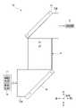
図1は、本発明の眼科装置1の構成の一例を示す概略図である。なお、本実施形態では、眼科装置1として、眼底カメラと、光コヒーレンストモグラフィ(Optical Coherence Tomography:OCT)を用いて断層像を得る光干渉断層計と、を組み合わせた複合機を例に挙げて説明を行う。
[Configuration of ophthalmic appliances]
FIG. 1 is a schematic view showing an example of the configuration of theophthalmic apparatus 1 of the present invention. In this embodiment, as anophthalmic apparatus 1, a multifunction device that combines a fundus camera and an optical coherence tomography that obtains a tomographic image using optical coherence tomography (OCT) is taken as an example. Give an explanation.

図1に示すように、眼科装置1は、眼底カメラユニット2、OCTユニット100、及び演算制御ユニット200を備える。眼底カメラユニット2は、従来の眼底カメラとほぼ同様の光学系を有する。OCTユニット100には、眼底のOCT画像を取得するための光学系が設けられている。演算制御ユニット200は、各種の演算処理及び制御処理等を実行するコンピュータである。 As shown in FIG. 1, theophthalmic apparatus 1 includes a fundus camera unit 2, anOCT unit 100, and anarithmetic control unit 200. The fundus camera unit 2 has an optical system substantially similar to that of a conventional fundus camera. TheOCT unit 100 is provided with an optical system for acquiring an OCT image of the fundus. Thearithmetic control unit 200 is a computer that executes various arithmetic processing, control processing, and the like.

[眼底カメラユニット]
図1に示す眼底カメラユニット2には、被検眼Eの眼底Efの表面形態を表す2次元画像(眼底像)を取得するための光学系として、照明光学系10と撮影光学系30とが設けられている。照明光学系10は眼底Efに照明光を照射する。撮影光学系30は、この照明光の眼底反射光を、CMOS(complementary metal oxide semiconductor)型又はCCD(Charge Coupled Device)型のイメージセンサ35,38に導く。また、撮影光学系30は、OCTユニット100からの信号光を眼底Efに導くと共に、眼底Efを経由した信号光をOCTユニット100に導く。
[Fundus camera unit]
The fundus camera unit 2 shown in FIG. 1 is provided with an illuminationoptical system 10 and a photographingoptical system 30 as an optical system for acquiring a two-dimensional image (fundus image) showing the surface morphology of the fundus Ef of the eye E to be inspected. Has been done. The illuminationoptical system 10 irradiates the fundus Ef with illumination light. The photographingoptical system 30 guides the fundus reflected light of the illumination light to CMOS (complementary metal oxide semiconductor) type or CCD (Charge Coupled Device)type image sensors 35 and 38. Further, the photographingoptical system 30 guides the signal light from theOCT unit 100 to the fundus Ef and guides the signal light passing through the fundus Ef to theOCT unit 100.

照明光学系10の観察光源11は、例えばハロゲンランプ又はLED(Light Emitting Diode)光源等が用いられ、観察照明光を出射する。観察光源11から出射された観察照明光は、反射ミラー12により反射され、集光レンズ13を経由し、可視カットフィルタ14を透過して近赤外光となる。さらに、観察照明光は、撮影光源15の近傍にて一旦集束し、ミラー16により反射され、リレーレンズ17,18、絞り19、及びリレーレンズ20を経由する。そして、観察照明光は、孔開きミラー21の周辺部(孔部の周囲の領域)にて反射され、ダイクロイックミラー46を透過し、対物レンズ22により屈折されて眼底Efを照明する。 As theobservation light source 11 of the illuminationoptical system 10, for example, a halogen lamp or an LED (Light Emitting Diode) light source is used, and the observation illumination light is emitted. The observation illumination light emitted from theobservation light source 11 is reflected by thereflection mirror 12, passes through thecondenser lens 13, passes through thevisible cut filter 14, and becomes near-infrared light. Further, the observation illumination light is once focused in the vicinity of the photographinglight source 15, reflected by themirror 16, and passes through therelay lenses 17, 18, thediaphragm 19, and therelay lens 20. Then, the observation illumination light is reflected at the peripheral portion of the perforated mirror 21 (the region around the perforated portion), passes through thedichroic mirror 46, is refracted by theobjective lens 22, and illuminates the fundus Ef.

観察照明光の眼底反射光は、対物レンズ22により屈折され、ダイクロイックミラー46を透過し、孔開きミラー21の中心領域に形成された孔部を通過し、ダイクロイックミラー55を透過し、合焦レンズ31を経由し、ミラー32により反射される。さらに、この眼底反射光は、ハーフミラー39Aを透過し、ダイクロイックミラー33により反射され、集光レンズ34によりイメージセンサ35の受光面に結像される。イメージセンサ35は、眼底反射光を撮像(受光)して撮像信号を出力する。表示装置3には、イメージセンサ35から出力された撮像信号に基づく観察画像が表示される。なお、撮影光学系30のピントが被検眼Eの前眼部Eaに合わせられている場合、この前眼部Eaの観察画像が表示装置3に表示される。 The fundus reflected light of the observation illumination light is refracted by theobjective lens 22, passes through thedichroic mirror 46, passes through the hole formed in the central region of theperforated mirror 21, passes through thedichroic mirror 55, and is a focusing lens. It is reflected by themirror 32 via 31. Further, the fundus reflected light passes through thehalf mirror 39A, is reflected by thedichroic mirror 33, and is imaged on the light receiving surface of theimage sensor 35 by thecondenser lens 34. Theimage sensor 35 captures (receives light) the fundus reflected light and outputs an image pickup signal. Thedisplay device 3 displays an observation image based on the image pickup signal output from theimage sensor 35. When the focus of the photographingoptical system 30 is on the anterior eye portion Ea of the eye to be inspected E, the observation image of the anterior eye portion Ea is displayed on thedisplay device 3.

撮影光源15は、例えばキセノンランプ又はLED光源等が用いられ、撮影照明光を出射する。撮影光源15から出射された撮影照明光は、既述の観察照明光と同様の経路を通って眼底Efに照射される。撮影照明光の眼底反射光は、観察照明光の眼底反射光と同様の経路を通ってダイクロイックミラー33まで導かれ、ダイクロイックミラー33を透過し、ミラー36により反射され、集光レンズ37によりイメージセンサ38の受光面に結像される。 As the photographinglight source 15, for example, a xenon lamp or an LED light source is used, and the photographing illumination light is emitted. The photographing illumination light emitted from the photographinglight source 15 irradiates the fundus Ef through the same path as the above-mentioned observation illumination light. The fundus reflected light of the photographing illumination light is guided to thedichroic mirror 33 through the same path as the fundus reflected light of the observation illumination light, passes through thedichroic mirror 33, is reflected by themirror 36, and is reflected by thecondenser lens 37. An image is formed on the light receiving surface of 38.

イメージセンサ38は、眼底反射光を撮像(受光)して撮像信号を出力する。表示装置3には、イメージセンサ38から出力された撮像信号に基づく撮影画像が表示される。なお、観察画像を表示する表示装置3と撮影画像を表示する表示装置3とは、同一のものであってもよいし、異なるものであってもよい。 Theimage sensor 38 captures (receives) the fundus reflected light and outputs an image pickup signal. Thedisplay device 3 displays a captured image based on the image pickup signal output from theimage sensor 38. Thedisplay device 3 for displaying the observed image and thedisplay device 3 for displaying the captured image may be the same or different.

LCD(Liquid Crystal Display)39は、固視標及び視力測定用指標などを表示する。固視標は被検眼Eを固視させるための指標であり、眼底撮影時及びOCT計測時などに使用される。 The LCD (Liquid Crystal Display) 39 displays a fixative, an index for measuring visual acuity, and the like. The fixative is an index for fixing the eye E to be inspected, and is used at the time of fundus photography, OCT measurement, and the like.

LCD39から出力された光は、その一部がハーフミラー39Aにて反射され、ミラー32に反射され、合焦レンズ31及びダイクロイックミラー55を経由し、孔開きミラー21の孔部を通過し、ダイクロイックミラー46を透過し、対物レンズ22により屈折されて眼底Efに投影される。これにより、被検眼Eに対して固視標及び視力測定用指標などを呈示することができる。 A part of the light output from theLCD 39 is reflected by thehalf mirror 39A, reflected by themirror 32, passes through the focusinglens 31 and thedichroic mirror 55, passes through the hole of theperforated mirror 21, and is dichroic. It passes through themirror 46, is reflected by theobjective lens 22, and is projected onto the fundus Ef. This makes it possible to present a fixative, an index for measuring visual acuity, and the like to the eye E to be inspected.

さらに、眼底カメラユニット2には、従来の眼底カメラと同様にアライメント光学系50とフォーカス光学系60とが設けられている。アライメント光学系50は、被検眼Eに対する装置光学系の位置合わせ(アライメント)を行うためのアライメント指標を生成する。フォーカス光学系60は、眼底Efに対してフォーカス(ピント)を合わせるためのスプリット指標を生成する。 Further, the fundus camera unit 2 is provided with an alignmentoptical system 50 and a focusoptical system 60, as in the conventional fundus camera. The alignmentoptical system 50 generates an alignment index for aligning the device optical system with respect to the eye E to be inspected. The focusoptical system 60 generates a split index for focusing on the fundus Ef.

アライメント光学系50のLED51から出射されたアライメント光は、絞り52,53及びリレーレンズ54を経由してダイクロイックミラー55により反射され、孔開きミラー21の孔部を通過し、ダイクロイックミラー46を透過し、対物レンズ22により被検眼Eの前眼部Eaの角膜に投影される。 The alignment light emitted from theLED 51 of the alignmentoptical system 50 is reflected by thedichroic mirror 55 via thediaphragms 52 and 53 and therelay lens 54, passes through the hole portion of theperforated mirror 21, and passes through thedichroic mirror 46. Is projected onto the corneum of the anterior segment Ea of the subject E by theobjective lens 22.

アライメント光の角膜反射光は、対物レンズ22、ダイクロイックミラー46、及び孔開きミラー21の孔部を経由し、その一部がダイクロイックミラー55を透過し、合焦レンズ31を通過し、ミラー32により反射され、ハーフミラー39Aを透過し、ダイクロイックミラー33に反射され、集光レンズ34によりイメージセンサ35の受光面に投影される。イメージセンサ35は、アライメント光の角膜反射光を撮像(受光)して撮像信号を出力する。これにより、表示装置3に、観察画像と共にアライメント指標が表示される。そして、ユーザは、従来の眼底カメラと同様の操作を行ってアライメントを実施する。また、演算制御ユニット200がアライメント指標の位置を解析して光学系を移動させることによりアライメント(オートアライメント)を行ってもよい。 The corneal reflected light of the alignment light passes through the holes of theobjective lens 22, thedichroic mirror 46, and theperforated mirror 21, and a part of the light passes through thedichroic mirror 55, passes through the focusinglens 31, and is transmitted by themirror 32. It is reflected, passes through thehalf mirror 39A, is reflected by thedichroic mirror 33, and is projected onto the light receiving surface of theimage sensor 35 by thecondenser lens 34. Theimage sensor 35 captures (receives) the corneal reflected light of the alignment light and outputs an image pickup signal. As a result, the alignment index is displayed on thedisplay device 3 together with the observation image. Then, the user performs the alignment by performing the same operation as that of the conventional fundus camera. Further, thearithmetic control unit 200 may analyze the position of the alignment index and move the optical system to perform alignment (auto alignment).

フォーカス調整を行う際には、照明光学系10の光路上に反射棒67の反射面がセットされる。フォーカス光学系60のLED61から出射されたフォーカス光は、リレーレンズ62を通過し、スプリット指標板63により2つの光束に分離され、二孔絞り64を通過し、ミラー65に反射され、集光レンズ66により反射棒67の反射面に一旦結像され、反射面にてリレーレンズ20に向けて反射される。さらにフォーカス光は、リレーレンズ20を経由し、孔開きミラー21に反射され、ダイクロイックミラー46を透過し、対物レンズ22により屈折されて眼底Efに投影される。 When adjusting the focus, the reflecting surface of the reflectingrod 67 is set on the optical path of the illuminationoptical system 10. The focus light emitted from theLED 61 of the focusoptical system 60 passes through therelay lens 62, is separated into two light beams by thesplit index plate 63, passes through the two-hole aperture 64, is reflected by themirror 65, and is a condenser lens. The image is once formed on the reflecting surface of the reflectingrod 67 by 66, and is reflected toward therelay lens 20 on the reflecting surface. Further, the focus light passes through therelay lens 20, is reflected by theperforated mirror 21, passes through thedichroic mirror 46, is refracted by theobjective lens 22, and is projected onto the fundus Ef.

フォーカス光の眼底反射光は、アライメント光の角膜反射光と同様の経路を通ってCCDイメージセンサ35により撮像(受光)される。イメージセンサ35は、フォーカス光の眼底反射光を撮像(受光)して撮像信号を出力する。これにより、表示装置3に観察画像と共にスプリット指標が表示される。演算制御ユニット200は、従来と同様に、スプリット指標の位置を解析して合焦レンズ31及びフォーカス光学系60を移動させてピント合わせを自動で行う。また、ユーザがスプリット指標を視認しつつ手動でピント合わせを行ってもよい。 The fundus reflected light of the focus light is imaged (received) by theCCD image sensor 35 through the same path as the corneal reflected light of the alignment light. Theimage sensor 35 captures (receives light) the fundus reflected light of the focus light and outputs an image pickup signal. As a result, the split index is displayed on thedisplay device 3 together with the observation image. Thearithmetic control unit 200 analyzes the position of the split index and moves the focusinglens 31 and the focusoptical system 60 to automatically perform focusing, as in the conventional case. Further, the user may manually focus while visually recognizing the split index.

ダイクロイックミラー46は、眼底撮影用の光路からOCT計測用の光路を分岐させている。ダイクロイックミラー46は、OCT計測に用いられる波長帯の光を反射し、眼底撮影用の光を透過させる。このOCT計測用の光路には、OCTユニット100側から順に、コリメータレンズユニット40と、光路長変更部41と、ガルバノスキャナ42と、合焦レンズ43と、ミラー44と、リレーレンズ45と、が設けられている。 Thedichroic mirror 46 branches an optical path for OCT measurement from an optical path for fundus photography. Thedichroic mirror 46 reflects light in the wavelength band used for OCT measurement and transmits light for fundus photography. The optical path for OCT measurement includes acollimator lens unit 40, an optical pathlength changing unit 41, agalvano scanner 42, a focusinglens 43, amirror 44, and arelay lens 45 in order from theOCT unit 100 side. It is provided.

光路長変更部41は、図1に示す矢印の方向に移動可能とされ、OCT計測用の光路の光路長を変更する。この光路長の変更は、被検眼Eの眼軸長に応じた光路長の補正、及び干渉状態の調整などに利用される。光路長変更部41は、例えばコーナーキューブと、これを移動する機構と、を含む。 The optical pathlength changing unit 41 is movable in the direction of the arrow shown in FIG. 1, and changes the optical path length of the optical path for OCT measurement. This change in the optical path length is used for correcting the optical path length according to the axial length of the eye E to be inspected, adjusting the interference state, and the like. The optical pathlength changing unit 41 includes, for example, a corner cube and a mechanism for moving the corner cube.

ガルバノスキャナ42は、OCT計測用の光路を通過する信号光の進行方向を変更する。これにより、眼底Efを信号光で走査することができる。ガルバノスキャナ42は、たとえば、信号光をx方向に走査するガルバノミラーと、y方向に走査するガルバノミラーと、これらを独立に駆動する機構とを含む。これにより、信号光をxy平面上の任意の方向に走査することができる。 Thegalvano scanner 42 changes the traveling direction of the signal light passing through the optical path for OCT measurement. Thereby, the fundus Ef can be scanned by the signal light. Thegalvano scanner 42 includes, for example, a galvano mirror that scans signal light in the x direction, a galvano mirror that scans in the y direction, and a mechanism that independently drives them. As a result, the signal light can be scanned in any direction on the xy plane.

眼底カメラユニット2には2台の前眼部カメラ300が設けられている。各前眼部カメラ300は、前眼部Eaを異なる方向から実質的に同時に撮影する。また、各前眼部カメラ300は、照明光学系10の光路及び撮影光学系30の光路から外れた位置に設けられている。そして、各前眼部カメラ300は、被検眼Eが実質的に同じ位置(向き)にある状態での被検眼Eの撮影画像をそれぞれ取得する。各撮影画像は、演算制御ユニット200による被検眼Eの特徴部位の三次元位置の解析に用いられる。 The fundus camera unit 2 is provided with twofront eye cameras 300. Eachanterior segment camera 300 captures the anterior segment Ea from different directions substantially simultaneously. Further, eachanterior segment camera 300 is provided at a position deviating from the optical path of the illuminationoptical system 10 and the optical path of the photographingoptical system 30. Then, eachanterior eye camera 300 acquires a photographed image of the eye E to be inspected in a state where the eye E to be inspected is in substantially the same position (orientation). Each captured image is used for analysis of the three-dimensional position of the characteristic portion of the eye E to be inspected by thearithmetic control unit 200.

OCTユニット100には、眼底EfのOCT画像を取得するための光学系が設けられている。この光学系は、従来のスペクトラルドメインタイプのOCT装置と同様の構成を有する。すなわち、この光学系は、低コヒーレンス光を参照光と信号光に分割し、眼底Efを経由した信号光と参照光路を経由した参照光とを干渉させて干渉光を生成し、この干渉光のスペクトル成分を検出する。この検出結果(検出信号)は、OCTユニット100から演算制御ユニット200へ出力される。なお、OCTユニット100の光学系の具体的な構成については公知技術(例えば上記特許文献1参照)であるので、ここでは具体的な説明は省略する。 TheOCT unit 100 is provided with an optical system for acquiring an OCT image of the fundus Ef. This optical system has a configuration similar to that of a conventional spectral domain type OCT device. That is, this optical system divides the low coherence light into reference light and signal light, and causes the signal light passing through the fundus Ef and the reference light passing through the reference optical path to interfere with each other to generate interference light, and the interference light is generated. Detect spectral components. This detection result (detection signal) is output from theOCT unit 100 to thearithmetic control unit 200. Since the specific configuration of the optical system of theOCT unit 100 is a known technique (see, for example,Patent Document 1 above), a specific description thereof will be omitted here.

演算制御ユニット200は、OCTユニット100から入力される検出信号を解析して眼底EfのOCT画像を形成する。なお、OCT画像の具体的な形成方法は、従来のスペクトラルドメインタイプのOCT装置と同様である。また、演算制御ユニット200は、眼底カメラユニット2、表示装置3、及びOCTユニット100の各部の動作を統括制御する。 Thearithmetic control unit 200 analyzes the detection signal input from theOCT unit 100 to form an OCT image of the fundus Ef. The specific method for forming the OCT image is the same as that of the conventional spectral domain type OCT apparatus. Further, thearithmetic control unit 200 collectively controls the operations of the fundus camera unit 2, thedisplay device 3, and theOCT unit 100.

演算制御ユニット200は、例えば従来のコンピュータと同様に、マイクロプロセッサ、メモリ、ハードディスクドライブ、通信インターフェイス、操作デバイス(キーボード等)、及び表示デバイス(LCD等)などを備える。ハードディスクドライブ等の記憶装置には、眼科装置1を制御するためのコンピュータプログラムが記憶されている。また、演算制御ユニット200は、各種の回路基板、例えばOCT画像を形成するための回路基板を備えていてもよい。 Thearithmetic control unit 200 includes, for example, a microprocessor, a memory, a hard disk drive, a communication interface, an operation device (keyboard, etc.), a display device (LCD, etc.), and the like, as in a conventional computer. A computer program for controlling theophthalmologic device 1 is stored in a storage device such as a hard disk drive. Further, thearithmetic control unit 200 may include various circuit boards, for example, circuit boards for forming OCT images.

[レンズユニットの構成]
照明光学系10のミラー16と孔開きミラー21との間には、共通の光軸OP(図3等参照)を有し、且つ観察照明光及び撮影照明光(以下、単に照明光と略す)が通過する既述のリレーレンズ17,18,20が配置されている。そして、これらリレーレンズ17,18,20は、後述のレンズユニット70(図2参照)の一部を構成し、且つこのレンズユニット70のレンズ収納筒71(図2参照)の内部に非接着で固定されている。すなわち、ミラー16と孔開きミラー21との間には、レンズユニット70が設けられている。以下、レンズユニット70の詳細構成について説明する。
[Construction of lens unit]
Themirror 16 of the illuminationoptical system 10 and theperforated mirror 21 have a common optical axis OP (see FIG. 3 and the like), and the observation illumination light and the photographing illumination light (hereinafter, simply abbreviated as illumination light). The above-mentionedrelay lenses 17, 18 and 20 through which the light passes are arranged. Therelay lenses 17, 18 and 20 form a part of the lens unit 70 (see FIG. 2) described later, and are not adhered to the inside of the lens storage cylinder 71 (see FIG. 2) of thelens unit 70. It is fixed. That is, alens unit 70 is provided between themirror 16 and theperforated mirror 21. Hereinafter, the detailed configuration of thelens unit 70 will be described.

なお、説明及び図面の煩雑化を防止するため、リレーレンズ17,18,20を2枚の第1レンズ74及び第2レンズ75(図3参照)に置き換えると共に、光軸OP上のリレーレンズ17,18,20以外の構成(絞り19及びフォーカス光学系60)については図示を省略する。また、図1では、ミラー16及び孔開きミラー21の双方による照明光の屈曲角度が90°未満であるが、以下の説明では双方による照明光の屈曲角度が90°であるものとして説明を行う。 In order to prevent the explanation and drawings from being complicated, therelay lenses 17, 18 and 20 are replaced with twofirst lenses 74 and a second lens 75 (see FIG. 3), and therelay lens 17 on the optical axis OP is replaced. Illustrations are omitted for configurations other than, 18, and 20 (aperture 19 and focus optical system 60). Further, in FIG. 1, the bending angle of the illumination light by both themirror 16 and theperforated mirror 21 is less than 90 °, but in the following description, it is assumed that the bending angle of the illumination light by both of them is 90 °. ..

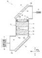
図2は、レンズユニット70の側面図である。図3は、図2中のレンズユニット70のレンズ収納筒71のみを断面図に置き換えた図である。図4は、レンズユニット70の分解図である。図5は、レンズユニット70の断面図である。なお、図中の左右方向、上下方向、及び前後方向は、互いに直交している。また、本実施形態では、図中の上下方向が第1レンズ74及び第2レンズ75の光軸OPの光軸方向に平行な方向になる。そして、図中の下方向側が本発明の光軸方向の一方向側に相当し、且つ図中の上方向側が本発明の光軸方向の他方向側に相当する。 FIG. 2 is a side view of thelens unit 70. FIG. 3 is a diagram in which only thelens storage cylinder 71 of thelens unit 70 in FIG. 2 is replaced with a cross-sectional view. FIG. 4 is an exploded view of thelens unit 70. FIG. 5 is a cross-sectional view of thelens unit 70. The left-right direction, the up-down direction, and the front-back direction in the figure are orthogonal to each other. Further, in the present embodiment, the vertical direction in the drawing is parallel to the optical axis direction of the optical axis OP of thefirst lens 74 and thesecond lens 75. The downward side in the figure corresponds to one direction side in the optical axis direction of the present invention, and the upward side in the figure corresponds to the other direction side in the optical axis direction of the present invention.

図2から図5に示すように、レンズユニット70は、レンズ収納筒71と、下側ミラー保持筒72A及び上側ミラー保持筒72Bと、規制環73と、第1レンズ74及び第2レンズ75と、間隔環76と、押え環77と、を備える。 As shown in FIGS. 2 to 5, thelens unit 70 includes alens storage cylinder 71, a lowermirror holding cylinder 72A and an uppermirror holding cylinder 72B, aregulation ring 73, afirst lens 74, and asecond lens 75. , Aspacing ring 76 and apresser ring 77.

レンズ収納筒71は、光軸OPの光軸方向(以下、単に光軸方向という)に延びた筒形状を有している。このレンズ収納筒71の下方向側の端部には下側ミラー保持筒72Aが接続され、且つレンズ収納筒71の上方向側の端部には上側ミラー保持筒72Bが接続されている。なお、本実施形態では、レンズ収納筒71と各ミラー保持筒72A,72Bとが一体形成されているが、各々が別体で形成されていてもよい。 Thelens storage cylinder 71 has a tubular shape extending in the optical axis direction of the optical axis OP (hereinafter, simply referred to as the optical axis direction). A lowermirror holding cylinder 72A is connected to the lower end of thelens storage cylinder 71, and an uppermirror holding cylinder 72B is connected to the upper end of thelens storage cylinder 71. In the present embodiment, thelens storage cylinder 71 and themirror holding cylinders 72A and 72B are integrally formed, but each may be formed separately.

レンズ収納筒71は、その中心軸が光軸OPに一致するように照明光学系10内に配置されている。このレンズ収納筒71の内周面である筒内周面78(図4参照)は、規制環73、第1レンズ74、第2レンズ75、間隔環76、及び押え環77の各部材を収納する収納空間を形成する。また、レンズ収納筒71の下方向側の端部には、下側ミラー保持筒72Aの内部に連通する下側開口79Aが形成されていると共に、レンズ収納筒71の上方向側の端部には、上側ミラー保持筒72Bの内部に連通する上側開口79Bが形成されている。さらに、レンズ収納筒71の筒内周面78には、後述の係合穴87(図2参照)がその周方向に沿って等間隔に4つ形成されている。 Thelens storage cylinder 71 is arranged in the illuminationoptical system 10 so that its central axis coincides with the optical axis OP. The inner peripheral surface 78 (see FIG. 4), which is the inner peripheral surface of thelens storage cylinder 71, houses the members of theregulation ring 73, thefirst lens 74, thesecond lens 75, thespacing ring 76, and the holdingring 77. Form a storage space to be used. Further, alower opening 79A communicating with the inside of the lowermirror holding cylinder 72A is formed at the lower end of thelens storage cylinder 71, and the upper end of thelens storage cylinder 71 is formed. Is formed with anupper opening 79B communicating with the inside of the uppermirror holding cylinder 72B. Further, four engaging holes 87 (see FIG. 2), which will be described later, are formed at equal intervals along the circumferential direction on the innerperipheral surface 78 of thelens storage cylinder 71.

レンズ収納筒71の内部には、観察光源11に近い側から順に、規制環73、第1レンズ74、間隔環76、第2レンズ75、及び押え環77が配置されている。規制環73は、レンズ収納筒71の内部に予め固定されている。一方、第1レンズ74、間隔環76、第2レンズ75、及び押え環77は、上側開口79Bよりレンズ収納筒71の内部に収納される。 Inside thelens storage cylinder 71, aregulation ring 73, afirst lens 74, aspacing ring 76, asecond lens 75, and apresser ring 77 are arranged in order from the side closer to the observationlight source 11. Theregulation ring 73 is fixed in advance inside thelens storage cylinder 71. On the other hand, thefirst lens 74, thespacing ring 76, thesecond lens 75, and thepresser ring 77 are housed inside thelens storage cylinder 71 through theupper opening 79B.

下側ミラー保持筒72Aは、下側開口79Aに対向する位置にミラー16を保持する。この下側ミラー保持筒72Aの内部には、各光源11,15からミラー16に向けて入射する照明光と、ミラー16で反射され且つミラー16から下側開口79Aに入射する照明光と、が通過する光路空間81が形成されている。この光路空間81は、下側開口79Aを介してレンズ収納筒71の内部に連通している。 The lowermirror holding cylinder 72A holds themirror 16 at a position facing thelower opening 79A. Inside the lowermirror holding cylinder 72A, there are illumination light incident from thelight sources 11 and 15 toward themirror 16 and illumination light reflected by themirror 16 and incident on thelower opening 79A from themirror 16. Anoptical path space 81 to pass through is formed. Theoptical path space 81 communicates with the inside of thelens storage cylinder 71 via thelower opening 79A.

上側ミラー保持筒72Bは、上側開口79Bに対向する位置に孔開きミラー21を保持する。この上側ミラー保持筒72Bの内部には、レンズ収納筒71の内部を通過して孔開きミラー21に入射する照明光と、孔開きミラー21により被検眼Eに向けて反射された照明光と、被検眼にて反射され且つ孔開きミラー21の孔部を通ってイメージセンサ35,38に入射する反射光と、が通過する光路空間82が形成されている。この光路空間82は、上側開口79Bを介してレンズ収納筒71の内部に連通している。 The uppermirror holding cylinder 72B holds theperforated mirror 21 at a position facing theupper opening 79B. Inside the uppermirror holding cylinder 72B, illumination light that passes through the inside of thelens storage cylinder 71 and is incident on theperforated mirror 21, and illumination light that is reflected by theperforated mirror 21 toward the eye E to be inspected. Anoptical path space 82 is formed in which the reflected light reflected by the eye to be inspected and incident on theimage sensors 35 and 38 through the hole of theperforated mirror 21 and the reflected light passing through theimage sensors 35 and 38. Theoptical path space 82 communicates with the inside of thelens storage cylinder 71 via theupper opening 79B.

規制環73は、本発明の規制部材に相当するものである。この規制環73は、略環状(略筒状)に形成されており、照明光の光路(光軸OP)が貫通する貫通穴73a(本発明の第2貫通穴に相当)を有している。また、規制環73は、その外径がレンズ収納筒71の内径と略同一の大きさに形成されているため、規制環73(貫通穴73a)の中心が光軸OPに一致(略一致を含む、以下同じ)する。 Theregulation ring 73 corresponds to the regulation member of the present invention. Theregulation ring 73 is formed in a substantially annular shape (substantially cylindrical shape), and has a throughhole 73a (corresponding to the second through hole of the present invention) through which the optical path (optical axis OP) of the illumination light penetrates. .. Further, since the outer diameter of theregulation ring 73 is formed to be substantially the same as the inner diameter of thelens storage cylinder 71, the center of the regulation ring 73 (throughhole 73a) coincides with the optical axis OP (substantially coincides). Including, the same applies below).

規制環73は、筒内周面78の下方向側の端部、より具体的には第1レンズ74よりも下方向側の位置に非接着で移動不能に設けられている。例えば、規制環73は、レンズ収納筒71(筒内周面78)と一体に形成されている。或いは、レンズ収納筒71と下側ミラー保持筒72Aとが別体で形成されている場合には、規制環73を下側ミラー保持筒72Aと一体に形成し、この下側ミラー保持筒72Aをレンズ収納筒71に接続する際に、規制環73を下側開口79A内に嵌合させてもよい。なお、レンズ収納筒71内で規制環73を非接着で固定する方法は上記方法に限定されるものではなく、公知の方法を採用することができる。 The restrictingring 73 is provided at the lower end of the cylinder innerperipheral surface 78, more specifically, at a position on the lower side of thefirst lens 74, in a non-adhesive manner and immovable. For example, theregulation ring 73 is integrally formed with the lens storage cylinder 71 (cylinder inner peripheral surface 78). Alternatively, when thelens storage cylinder 71 and the lowermirror holding cylinder 72A are formed separately, theregulation ring 73 is integrally formed with the lowermirror holding cylinder 72A, and the lowermirror holding cylinder 72A is formed. When connecting to thelens storage cylinder 71, theregulation ring 73 may be fitted in thelower opening 79A. The method of fixing theregulation ring 73 in thelens storage cylinder 71 without adhesive is not limited to the above method, and a known method can be adopted.

規制環73の上方向側の端面は、第1レンズ74の周縁部が突き当てられる環状の突き当て面73b(図4参照)となる。従って、規制環73は、第1レンズ74の下方向側への移動(変位)を直接的に規制すると共に、後述の間隔環76を介して第2レンズ75の下方向側への移動も間接的に規制する。 The upper end surface of theregulation ring 73 is an annularabutting surface 73b (see FIG. 4) to which the peripheral edge portion of thefirst lens 74 is abutted. Therefore, theregulation ring 73 directly regulates the downward movement (displacement) of thefirst lens 74, and also indirectly regulates the downward movement (displacement) of thesecond lens 75 via theinterval ring 76 described later. Regulate.

第1レンズ74は例えば凸レンズであり、第2レンズ75は例えば凹レンズである。本実施形態では、第1レンズ74及び第2レンズ75の双方は、レンズ収納筒71の内部において光軸方向に移動自在に収納されている。そして、第1レンズ74は、規制環73の突き当て面73b上に配置される。また、第2レンズ75は、後述の間隔環76を間に挟んで第1レンズ74の上方向側に配置される。 Thefirst lens 74 is, for example, a convex lens, and thesecond lens 75 is, for example, a concave lens. In the present embodiment, both thefirst lens 74 and thesecond lens 75 are housed inside thelens storage cylinder 71 so as to be movable in the optical axis direction. Then, thefirst lens 74 is arranged on theabutting surface 73b of theregulation ring 73. Further, thesecond lens 75 is arranged on the upward side of thefirst lens 74 with theinterval ring 76 described later interposed therebetween.

また、第1レンズ74及び第2レンズ75の双方の直径は、レンズ収納筒71の内径と略同一の大きさに形成されている。このため、第1レンズ74及び第2レンズ75は、レンズ収納筒71の内部に収納されている状態では、各々の光軸OPが一致する。すなわち、第1レンズ74及び第2レンズ75は、共通の光軸OPを有する。 Further, the diameters of both thefirst lens 74 and thesecond lens 75 are formed to have substantially the same size as the inner diameter of thelens housing cylinder 71. Therefore, when thefirst lens 74 and thesecond lens 75 are housed inside thelens storage cylinder 71, their respective optical axes OPs match. That is, thefirst lens 74 and thesecond lens 75 have a common optical axis OP.

間隔環76は、略環状(略筒状)に形成されており、既述の照明光の光路が貫通する貫通穴76a(本発明の第3貫通穴に相当)を有している。間隔環76は、その下方向側の端面が第1レンズ74の周縁部に当接し、その上方向側の端面が第2レンズ75の周縁部に当接する。なお、各レンズ74,75の周縁部とは、例えばレンズとして機能する有効領域よりも外側の領域である。 Theinterval ring 76 is formed in a substantially annular shape (substantially cylindrical shape), and has a throughhole 76a (corresponding to the third through hole of the present invention) through which the optical path of the above-mentioned illumination light penetrates. The lower end surface of theinterval ring 76 abuts on the peripheral edge portion of thefirst lens 74, and the upper end surface thereof abuts on the peripheral edge portion of thesecond lens 75. The peripheral edge of each of thelenses 74 and 75 is, for example, a region outside the effective region that functions as a lens.

第1レンズ74及び第2レンズ75の双方の互いに対向する対向面は共にアーチ状の曲面であるため、第1レンズ74上に第2レンズ75を直接配置した場合、レンズ収納筒71内での各レンズ74,75の姿勢が安定しない。このため、間隔環76は、レンズ収納筒71内での各レンズ74,75の姿勢を安定させる。また、間隔環76の光軸方向の長さを調整することで、各レンズ74,75のレンズ間隔を任意に調整可能である。 Since the facing surfaces of both thefirst lens 74 and thesecond lens 75 facing each other are arch-shaped curved surfaces, when thesecond lens 75 is directly arranged on thefirst lens 74, the inside of thelens storage cylinder 71 The posture of eachlens 74 and 75 is not stable. Therefore, thespacing ring 76 stabilizes the posture of eachlens 74, 75 in thelens storage cylinder 71. Further, the lens spacing of each of thelenses 74 and 75 can be arbitrarily adjusted by adjusting the length of thespacing ring 76 in the optical axis direction.

押え環77は、各種の樹脂材料で環状に形成されている。また、押え環77は、既述の照明光の光路が貫通する貫通穴77a(本発明の第1貫通穴に相当)を有している。さらに、押え環77は、その外径がレンズ収納筒71の内径に合わせて形成されており、筒内周面78に対してスナップフィット方式で固定されている。これにより、押え環77(貫通穴77a)の中心位置が、光軸OPに一致する。 Thepresser ring 77 is formed of various resin materials in an annular shape. Further, thepresser ring 77 has a throughhole 77a (corresponding to the first through hole of the present invention) through which the optical path of the above-mentioned illumination light penetrates. Further, thepresser ring 77 is formed so that its outer diameter matches the inner diameter of thelens storage cylinder 71, and is fixed to the innerperipheral surface 78 of the cylinder by a snap-fit method. As a result, the center position of the presser ring 77 (throughhole 77a) coincides with the optical axis OP.

押え環77は、スナップフィット方式で筒内周面78に固定された場合に、その固定位置において第2レンズ75を下方向側に押さえ付ける。既述のように、第2レンズ75は、間隔環76及び第1レンズ74を介して、規制環73により下方向側への移動が規制されている。このため、押え環77は、規制環73との間で、第1レンズ74、間隔環76、及び第2レンズ75を挟持固定する。これにより、レンズ収納筒71内での第1レンズ74及び第2レンズ75の上下方向の位置が位置決めされる。 When thepresser ring 77 is fixed to the innerperipheral surface 78 of the cylinder by the snap-fit method, thepresser ring 77 presses thesecond lens 75 downward at the fixed position. As described above, thesecond lens 75 is restricted from moving downward by theregulation ring 73 via thespacing ring 76 and thefirst lens 74. Therefore, the holdingring 77 sandwiches and fixes thefirst lens 74, thespacing ring 76, and thesecond lens 75 with the regulatingring 73. As a result, the positions of thefirst lens 74 and thesecond lens 75 in thelens housing cylinder 71 in the vertical direction are positioned.

[押え環の構成]
図6は、押え環77をその上方向側から見た斜視図である。図7は、押え環77をその上方向側から見た上面図である。図6及び図7に示すように、押え環77は、既述の貫通穴77a(内周面)と、筒内周面78に対向する外周面である環外周面77bと、4つのスナップフィット係合部85と、を有する。また、押え環77の下方向側の端面は、第2レンズ75の周縁部を押さえ付ける環状の押え面77cとなる。
[Structure of presser ring]
FIG. 6 is a perspective view of thepresser ring 77 as viewed from above. FIG. 7 is a top view of thepresser ring 77 as viewed from above. As shown in FIGS. 6 and 7, thepresser ring 77 has a throughhole 77a (inner peripheral surface) described above, a ring outerperipheral surface 77b which is an outer peripheral surface facing the innerperipheral surface 78 of the cylinder, and four snap fits. It has an engagingportion 85 and. Further, the lower end surface of thepressing ring 77 is an annularpressing surface 77c that presses the peripheral edge portion of thesecond lens 75.

4つのスナップフィット係合部85は、環外周面77bの周方向に沿って等間隔で設けられている。具体的に、環外周面77bにはその周方向に沿って溝部88が4つ形成されており、各スナップフィット係合部85は各溝部88内にそれぞれ設けられている。各スナップフィット係合部85は、筒内周面78に形成されている4つの係合穴87(本発明のスナップフィット被係合部に相当)にそれぞれ係合する。 The four snap-fit engaging portions 85 are provided at equal intervals along the circumferential direction of the ring outerperipheral surface 77b. Specifically, fourgroove portions 88 are formed on the ring outerperipheral surface 77b along the circumferential direction thereof, and each snap-fit engaging portion 85 is provided in eachgroove portion 88. Each snap-fit engaging portion 85 engages with each of the four engaging holes 87 (corresponding to the snap-fit engaged portion of the present invention) formed in the innerperipheral surface 78 of the cylinder.

図8は、図7中の8-8線(光軸方向に垂直方向)に沿った押え環77の断面図である。図9は、図7中の点線円Uで示した部分の拡大図である。なお、各スナップフィット係合部85は全て同じ構造であるので、ここでは1つのスナップフィット係合部85の構造について説明する。 FIG. 8 is a cross-sectional view of the holdingring 77 along the line 8-8 (direction perpendicular to the optical axis direction) in FIG. 7. FIG. 9 is an enlarged view of the portion shown by the dotted line circle U in FIG. 7. Since each snap-fit engaging portion 85 has the same structure, the structure of one snap-fit engaging portion 85 will be described here.

図6から図9に示すように、スナップフィット係合部85は、押え環77の一部であって且つ溝部88の底を構成する底部89により支持されている。スナップフィット係合部85は、押え環77と一体に樹脂材料で形成されており、平板90と係合爪91と接続部92とを有する。なお、スナップフィット係合部85が、押え環77とは異なる材料で形成されていてもよい。 As shown in FIGS. 6 to 9, the snap-fit engaging portion 85 is supported by abottom portion 89 that is a part of the holdingring 77 and constitutes the bottom of thegroove portion 88. The snap-fit engaging portion 85 is formed of a resin material integrally with thepresser ring 77, and has aflat plate 90, an engagingclaw 91, and a connectingportion 92. The snap-fit engaging portion 85 may be made of a material different from that of thepresser ring 77.

平板90は、本発明の板状の可撓体に相当するものであり、光軸方向において環外周面77bの全域(略全域を含む)に亘って延在する形状を有している。なお、平板90の幅W(図7参照)は、溝部88の同方向の幅よりも小さく形成されている。 Theflat plate 90 corresponds to the plate-shaped flexible body of the present invention, and has a shape extending over the entire area (including substantially the entire area) of the ring outerperipheral surface 77b in the optical axis direction. The width W of the flat plate 90 (see FIG. 7) is formed to be smaller than the width of thegroove 88 in the same direction.

平板90は、筒内周面78に対向する第1面90aと、第1面90aとは反対側の面であって且つ底部89に対向する第2面90bと、を有する。なお、本実施形態において、第1面90aは環外周面77bの一部を構成している。 Theflat plate 90 has afirst surface 90a facing the innerperipheral surface 78 of the cylinder, and asecond surface 90b that is a surface opposite to thefirst surface 90a and faces thebottom portion 89. In this embodiment, thefirst surface 90a constitutes a part of the ring outerperipheral surface 77b.

平板90は、既述の通り樹脂材料で形成されているので可撓性(弾性)を有している。そして、平板90の上方向側の端部は後述の接続部92により固定されているが、平板90の下方向側の端部は非固定である。従って、平板90は、第1面90a側から底部89側に向けて押圧された場合に、下方向側の端部が底部89に近づくように弾性変形される。そして、この押圧が解除されると、平板90は自身の復元力によって元の形状に復元される。 Since theflat plate 90 is made of a resin material as described above, it has flexibility (elasticity). The upper end of theflat plate 90 is fixed by theconnection portion 92 described later, but the lower end of theflat plate 90 is not fixed. Therefore, when theflat plate 90 is pressed from thefirst surface 90a side toward thebottom portion 89 side, theflat plate 90 is elastically deformed so that the lower end portion approaches thebottom portion 89. Then, when this pressing is released, theflat plate 90 is restored to its original shape by its own restoring force.

係合爪91は、第1面90aの下方向側の端部に設けられている。係合爪91は、平板90の幅方向に沿って直線状に延び、且つ第1面90aから筒内周面78(係合穴87)に向けて突出した形状を有する。この係合爪91の上方向側の側面には、光軸方向に対して垂直な平面状の抜け止め面91aが形成されている。また、係合爪91の先端部(特に先端面と下方向側の端面とがなすコーナ部)には、曲面状に面取りされた面取り面91bが形成されている。 The engagingclaw 91 is provided at the lower end portion of thefirst surface 90a. The engagingclaw 91 extends linearly along the width direction of theflat plate 90 and has a shape protruding from thefirst surface 90a toward the inner peripheral surface 78 (engaging hole 87) of the cylinder. Aplanar retaining surface 91a perpendicular to the optical axis direction is formed on the upper side surface of the engagingclaw 91. Further, achamfered surface 91b chamfered in a curved shape is formed at the tip end portion of the engaging claw 91 (particularly, the corner portion formed by the tip end surface and the lower end surface).

接続部92は、第2面90bの上方向側の端部に設けられている。接続部92は、平板90と底部89との間に隙間を設けた状態で、平板90の上方向側の端部と底部89とを接続する。 The connectingportion 92 is provided at the upper end portion of thesecond surface 90b. The connectingportion 92 connects the upper end portion of theflat plate 90 and thebottom portion 89 with a gap provided between theflat plate 90 and thebottom portion 89.

[押え環及びスナップフィット係合部の寸法]
次に、押え環77及びスナップフィット係合部85の寸法の一例について説明する。なお、本発明は以下の寸法に限定されるものではない。
[Dimensions of presser ring and snap-fit engagement part]
Next, an example of the dimensions of thepresser ring 77 and the snap-fit engaging portion 85 will be described. The present invention is not limited to the following dimensions.

押え環77の外径D1を30.4mmとした場合、係合爪91を含めた押え環77の最大外径D2は33.0mmである(図8参照)。従って、個々の係合爪91の突出長さΔDは1.3mm[=(33.0-30.4)/2]となる。このように本実施形態では、係合爪91の突出長さを外径D1の約5%程度に調整している。なお、係合爪91の突出長さを短くした場合、例えば外径D1の約2.5%程度に調整した場合には、係合爪91が係合穴87から抜け易くなってしまう。従って、本実施形態では、係合穴87からの係合爪91の意図しない抜けを防止するため、係合爪91の突出長さを外径D1の約5%程度に調整している。 When the outer diameter D1 of thepresser ring 77 is 30.4 mm, the maximum outer diameter D2 of thepresser ring 77 including the engagingclaw 91 is 33.0 mm (see FIG. 8). Therefore, the protruding length ΔD of each engagingclaw 91 is 1.3 mm [= (33.0-30.4) / 2]. As described above, in the present embodiment, the protruding length of the engagingclaw 91 is adjusted to about 5% of the outer diameter D1. If the protruding length of the engagingclaw 91 is shortened, for example, if it is adjusted to about 2.5% of the outer diameter D1, the engagingclaw 91 tends to come off from the engaginghole 87. Therefore, in the present embodiment, in order to prevent the engagingclaw 91 from unintentionally coming off from the engaginghole 87, the protruding length of the engagingclaw 91 is adjusted to about 5% of the outer diameter D1.

レンズ収納筒71に収納される内容物(第1レンズ74、第2レンズ75、及び間隔環76)の質量を57gとした場合、この内容物に対応したスナップフィット係合部85の強度を確保するため、平板90の肉厚tを0.8mmとし、平板90の光軸軸方向の長さL1を5.5mm(係合爪91の形成部分を除いた長さL2は4.5mm)としている(図9参照)。また、平板90の幅Wを5.0mmとしている(図7参照)。これにより、スナップフィット係合部85の破損が防止される。 When the mass of the contents (first lens 74,second lens 75, and spacing ring 76) stored in thelens storage cylinder 71 is 57 g, the strength of the snap-fit engaging portion 85 corresponding to these contents is secured. Therefore, the wall thickness t of theflat plate 90 is set to 0.8 mm, and the length L1 of theflat plate 90 in the optical axis axis direction is set to 5.5 mm (the length L2 excluding the formed portion of the engagingclaw 91 is 4.5 mm). (See Fig. 9). Further, the width W of theflat plate 90 is set to 5.0 mm (see FIG. 7). This prevents the snap-fit engaging portion 85 from being damaged.

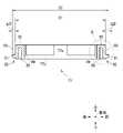
図10は、レンズ収納筒71の上方向側の端部の断面拡大図である。図10に示すように、レンズ収納筒71の筒内周面78には、4つの押え環77にそれぞれ対向する位置に既述の係合穴87が形成されている。すなわち、筒内周面78の周方向に沿って4つの係合穴87が等間隔で形成されている。各係合穴87には各々に対向するスナップフィット係合部85の係合爪91が係合する。これにより、筒内周面78に対して押え環77が非接着で固定される。 FIG. 10 is an enlarged cross-sectional view of the upper end of thelens storage cylinder 71. As shown in FIG. 10, on the innerperipheral surface 78 of thelens accommodating cylinder 71, the above-mentionedengaging holes 87 are formed at positions facing each of the fourpressing rings 77. That is, four engagingholes 87 are formed at equal intervals along the circumferential direction of the innerperipheral surface 78 of the cylinder. Each engaginghole 87 is engaged with an engagingclaw 91 of a snap-fit engaging portion 85 facing each other. As a result, thepressing ring 77 is fixed to the innerperipheral surface 78 of the cylinder without adhesion.

また、この場合、係合穴87ごとに、係合穴87の上方向側の穴内壁面87aに対して係合爪91の抜け止め面91aが引っ掛けられる。これにより、各係合爪91(押え環77)の上方向側への移動が規制される。 Further, in this case, the retainingsurface 91a of the engagingclaw 91 is hooked on theinner wall surface 87a of the hole on the upward side of the engaginghole 87 for each engaginghole 87. As a result, the upward movement of each engaging claw 91 (pressing ring 77) is restricted.

筒内周面78上での各係合穴87の形成位置は、規制環73の上下方向の位置と、レンズ収納筒71の内部に収納される内容物(第1レンズ74、間隔環76、及び第2レンズ75)の上下方向の厚みの合計値と、に基づき決定される。具体的には、各係合穴87の形成位置を、規制環73と押え環77との間の距離が、上述の厚みの合計値よりも僅かに小さくなるような位置に調整している。これにより、筒内周面78に押え環77が固定された場合に、押え環77によって上述の内容物が下方向側に押さえ付けられる。 The positions of forming the engagingholes 87 on the inner peripheral surface of thecylinder 78 are the vertical position of theregulation ring 73 and the contents housed inside the lens storage cylinder 71 (first lens 74, spacingring 76, etc.). And, it is determined based on the total value of the thickness in the vertical direction of the second lens 75). Specifically, the forming position of each engaginghole 87 is adjusted to a position where the distance between the regulatingring 73 and thepressing ring 77 is slightly smaller than the total value of the above-mentioned thicknesses. As a result, when thepresser ring 77 is fixed to the innerperipheral surface 78 of the cylinder, thepresser ring 77 presses the above-mentioned contents downward.

また、各係合穴87は、レンズ収納筒71の内外周面を貫通している。このため、レンズ収納筒71の外周面側に開口している各係合穴87の開口部から、係合爪91の先端部を筒内周面78側に向けてそれぞれ押圧することで、各係合爪91と各係合穴87との係合を解除することができる。これにより、レンズ収納筒71から押え環77を取り外すことができる。なお、レンズ収納筒71から押え環77を取り外す必要が無い場合には、各係合穴87を筒内周面78側のみで開口する非貫通穴に形成する。 Further, each engaginghole 87 penetrates the inner outer peripheral surface of thelens storage cylinder 71. Therefore, by pressing the tip of the engagingclaw 91 toward the innerperipheral surface 78 side of the engaginghole 87, which is open on the outer peripheral surface side of thelens storage cylinder 71, each of them is pressed. The engagement between the engagingclaw 91 and each engaginghole 87 can be released. As a result, thepresser ring 77 can be removed from thelens storage cylinder 71. When it is not necessary to remove thepresser ring 77 from thelens storage cylinder 71, each engaginghole 87 is formed as a non-through hole that opens only on the innerperipheral surface 78 side of the cylinder.

レンズ収納筒71の各レンズ74,75の収納部分における筒内周面78の内径D3は、各レンズ74,75の直径に合わせて例えば30.0mmに調整されている。一方、レンズ収納筒71の上方向側の端部における筒内周面78の内径D4は、既述の押え環77の最大外径D2に合わせて形成されている。なお、レンズ収納筒71の各係合穴87の形成部分における内周面の内径D5は、押え環77の外径D1に合わせて形成されている。このため、筒内周面78には、内径D4の部分と内径D5の部分との境界部分に両者を接続する傾斜面78aが形成されている。 The inner diameter D3 of the innerperipheral surface 78 of thelens 74, 75 of thelens storage cylinder 71 is adjusted to, for example, 30.0 mm according to the diameter of eachlens 74, 75. On the other hand, the inner diameter D4 of the innerperipheral surface 78 of thelens housing cylinder 71 at the upper end is formed in accordance with the maximum outer diameter D2 of thepresser ring 77 described above. The inner diameter D5 of the inner peripheral surface of the formed portion of each engaginghole 87 of thelens storage cylinder 71 is formed in accordance with the outer diameter D1 of thepresser ring 77. Therefore, on the innerperipheral surface 78 of the cylinder, aninclined surface 78a connecting the inner diameter D4 and the inner diameter D5 is formed at the boundary portion.

[押え環のレンズ収納筒への取付]
押え環77をレンズ収納筒71に取り付ける場合、予め上側開口79Bよりレンズ収納筒71の内部に第1レンズ74、間隔環76、及び第2レンズ75を挿入しておく。レンズ収納筒71の内部に挿入された第1レンズ74、間隔環76、及び第2レンズ75は、既述の規制環73によって下方向側への移動が規制された状態となる。
[Mounting the presser ring on the lens storage tube]
When thepresser ring 77 is attached to thelens storage cylinder 71, thefirst lens 74, thespacing ring 76, and thesecond lens 75 are previously inserted into thelens storage cylinder 71 from theupper opening 79B. Thefirst lens 74, theinterval ring 76, and thesecond lens 75 inserted inside thelens storage cylinder 71 are in a state where their downward movement is restricted by the above-mentionedrestriction ring 73.

次いで、押え環77を、レンズ収納筒71の上側開口79Bよりレンズ収納筒71の内部に挿入する。この挿入を継続すると、押え環77の各スナップフィット係合部85の係合爪91の先端部が傾斜面78aに接触する。 Next, thepresser ring 77 is inserted into thelens storage cylinder 71 through theupper opening 79B of thelens storage cylinder 71. When this insertion is continued, the tip of the engagingclaw 91 of each snap-fit engaging portion 85 of thepresser ring 77 comes into contact with theinclined surface 78a.

そして、押え環77の挿入を継続すると、傾斜面78aにより各係合爪91が各々に対向する底部89に向けて押圧される。これにより、各スナップフィット係合部85の平板90は、その下方向側の端部(係合爪91)が底部89に近づくように弾性変形される。その結果、押え環77の最大外径D2の大きさが内径D5(外径D1)の大きさまで縮小されるので、押え環77を、筒内周面78の中で各係合穴87が形成されている部分まで挿入させることができる。 Then, when the insertion of thepressing ring 77 is continued, each engagingclaw 91 is pressed toward thebottom portion 89 facing each other by theinclined surface 78a. As a result, theflat plate 90 of each snap-fit engaging portion 85 is elastically deformed so that the lower end portion (engaging claw 91) thereof approaches thebottom portion 89. As a result, the size of the maximum outer diameter D2 of thepresser ring 77 is reduced to the size of the inner diameter D5 (outer diameter D1), so that thepresser ring 77 is formed with each engaginghole 87 in the innerperipheral surface 78 of the cylinder. It is possible to insert up to the part that is.

さらに、押え環77の挿入を継続すると、押え環77が第2レンズ75に接触する。この接触後、押え環77を下方向側に押さえ付けることで、各係合爪91がそれぞれ各係合穴87に対向する位置まで移動される。これにより、筒内周面78による各係合爪91の押えが解除されるため、各平板90が元の形状に復元する。その結果、係合爪91ごとに、係合爪91に対向する係合穴87に挿入されて係合穴87と係合する。この際に、各係合爪91の先端部には面取り面91bが形成されているので、各係合爪91を各係合穴87に容易に挿入することができる。 Further, when the insertion of thepresser ring 77 is continued, thepresser ring 77 comes into contact with thesecond lens 75. After this contact, by pressing thepressing ring 77 downward, each engagingclaw 91 is moved to a position facing each engaginghole 87. As a result, the pressing of each engagingclaw 91 by the innerperipheral surface 78 of the cylinder is released, so that eachflat plate 90 is restored to its original shape. As a result, each engagingclaw 91 is inserted into the engaginghole 87 facing the engagingclaw 91 and engaged with the engaginghole 87. At this time, since the chamferedsurface 91b is formed at the tip of each engagingclaw 91, each engagingclaw 91 can be easily inserted into each engaginghole 87.

各係合爪91と各係合穴87との係合が完了すると、各係合爪91の抜け止め面91aがそれぞれ係合穴87の穴内壁面87aに引っ掛けられることにより、押え環77の上方向側への移動が確実に規制される。これにより、押え環77が、第2レンズ75等を下方向側に押さえ付けた状態のままで筒内周面78に固定される。その結果、押え環77及び規制環73により、第1レンズ74、間隔環76、及び第2レンズ75が上下方向に挟持固定される。 When the engagement between each engagingclaw 91 and each engaginghole 87 is completed, the retainingsurface 91a of each engagingclaw 91 is hooked on theinner wall surface 87a of the engaginghole 87, thereby being hooked on the holdingring 77. Movement in the direction is definitely restricted. As a result, thepresser ring 77 is fixed to the innerperipheral surface 78 of the cylinder while thesecond lens 75 or the like is pressed downward. As a result, thefirst lens 74, thespacing ring 76, and thesecond lens 75 are sandwiched and fixed in the vertical direction by thepressing ring 77 and the regulatingring 73.

また、レンズユニット70を含む照明光学系10では、各光源11,15側から各部品の寸法及び位置等の公差を積み上げて目標とする総合公差を定めている。この際に、本実施形態とは逆に、各係合爪91の下方向側の側面に抜け止め面91aが形成されていると、押え環77が上方向側に変位する可能性がある。この場合には、総合公差を大きくする必要があるため、レンズユニット70の組み立て精度が低下するおそれがある。これに対して、本実施形態では、各係合爪91の抜け止め面91aによって押え環77の上方向側への移動が確実に規制されるので、押え環77が第2レンズ75等を下方向側に押さえ付けた状態が維持される。その結果、上述の総合公差を小さくすることができるので、レンズユニット70の組み立て精度を上げることができる。 Further, in the illuminationoptical system 10 including thelens unit 70, the target total tolerance is determined by accumulating the tolerances such as the dimensions and positions of each component from thelight source 11 and 15 sides. At this time, contrary to the present embodiment, if the retainingsurface 91a is formed on the lower side surface of each engagingclaw 91, the holdingring 77 may be displaced upward. In this case, since it is necessary to increase the total tolerance, the assembly accuracy of thelens unit 70 may decrease. On the other hand, in the present embodiment, thepressing ring 77 is reliably restricted from moving upward by the retainingsurface 91a of each engagingclaw 91, so that thepressing ring 77 lowers thesecond lens 75 or the like. The state of being pressed down to the direction side is maintained. As a result, the above-mentioned total tolerance can be reduced, so that the assembly accuracy of thelens unit 70 can be improved.

[本実施形態の効果]
以上のように本実施形態では、レンズ収納筒71の筒内周面78に対して押え環77をスナップフィット方式で固定すると共に、この押え環77と規制環73とに間に各レンズ74,75等を挟持固定するため、接着剤を用いずにレンズユニット70を組み立てることができる。その結果、接着剤からのアウトガスの発生が防止される。また、レンズユニット70の組み立て作業が簡便になるので、作業者ごとのレンズユニット70の組み立て精度のばらつきが抑えられる。その結果、アウトガスの発生防止と、レンズユニット70の組立精度のばらつき低減とを両立することができる。
[Effect of this embodiment]
As described above, in the present embodiment, thepresser ring 77 is fixed to the innerperipheral surface 78 of thelens storage tube 71 by a snap-fit method, and eachlens 74 is placed between thepresser ring 77 and the restrictingring 73. Since the 75 and the like are sandwiched and fixed, thelens unit 70 can be assembled without using an adhesive. As a result, the generation of outgas from the adhesive is prevented. Further, since the assembly work of thelens unit 70 is simplified, the variation in the assembly accuracy of thelens unit 70 for each operator can be suppressed. As a result, it is possible to both prevent the generation of outgas and reduce the variation in the assembly accuracy of thelens unit 70.

[その他]
図11は、上記実施形態のレンズユニット70(図3参照)の変形例を説明するための説明図である。上記実施形態では、規制環73を第1レンズ74の周縁部に接触させ、且つ押え環77を第2レンズ75の周縁部に接触させているが、本発明はこれに限定されるものではない。
[others]
FIG. 11 is an explanatory diagram for explaining a modified example of the lens unit 70 (see FIG. 3) of the above embodiment. In the above embodiment, theregulation ring 73 is brought into contact with the peripheral edge portion of thefirst lens 74, and thepresser ring 77 is brought into contact with the peripheral edge portion of thesecond lens 75, but the present invention is not limited thereto. ..

図11に示すように、規制環73と第1レンズ74との間に間隔環76を介在させ、或いは押え環77と第2レンズ75との間に間隔環76を介在させてもよい。すなわち、押え環77及び規制環73により、各レンズ74,75等を間接的に挟持固定してもよい。これにより、下側開口79Aから上方向側に離れた位置に第1レンズ74を固定したり、或いは上側開口79Bから下方向側に離れた位置に第2レンズ75を固定したりする必要がある場合でも、レンズユニット70の組み立て作業を簡単に行うことができる。 As shown in FIG. 11, thespacing ring 76 may be interposed between theregulation ring 73 and thefirst lens 74, or thespacing ring 76 may be interposed between thepresser ring 77 and thesecond lens 75. That is, thelenses 74, 75, etc. may be indirectly sandwiched and fixed by thepresser ring 77 and theregulation ring 73. As a result, it is necessary to fix thefirst lens 74 at a position away from thelower opening 79A in the upward direction, or to fix thesecond lens 75 at a position away from theupper opening 79B in the downward direction. Even in this case, the assembly work of thelens unit 70 can be easily performed.

上記実施形態では、規制環73が環状に形成されている場合を例に挙げて説明したが、規制環73が筒内周面78の周方向に沿って複数(好ましくは3以上)に分割されていてもよい。この場合、規制環73の各分割体は、筒内周面78の周方向に沿って等間隔に配置されていることが好ましい。このように本発明の規制部材は、各レンズ74,75等の下方向側への移動を規制し、且つ照明光を通過させる形状であれば特に限定されない。 In the above embodiment, the case where theregulation ring 73 is formed in a ring shape has been described as an example, but theregulation ring 73 is divided into a plurality of (preferably 3 or more) along the circumferential direction of the innerperipheral surface 78 of the cylinder. May be. In this case, it is preferable that the divided bodies of theregulation ring 73 are arranged at equal intervals along the circumferential direction of the innerperipheral surface 78 of the cylinder. As described above, the restricting member of the present invention is not particularly limited as long as it has a shape that restricts the downward movement of thelenses 74, 75, etc. and allows the illumination light to pass therethrough.

上記実施形態では、環外周面77bに4つのスナップフィット係合部85が設けられている場合を例に挙げて説明したが、スナップフィット係合部85の数は3以下或いは5以上であってもよい。この場合には、スナップフィット係合部85の数に応じて、筒内周面78に形成する係合穴87の数を調整する。 In the above embodiment, the case where four snap-fit engaging portions 85 are provided on the ring outerperipheral surface 77b has been described as an example, but the number of snap-fit engaging portions 85 is 3 or less or 5 or more. May be good. In this case, the number of engagingholes 87 formed on the innerperipheral surface 78 of the cylinder is adjusted according to the number of snap-fit engaging portions 85.

上記実施形態では、係合爪91が平板90の第1面90aの下方向側の端部に設けられ、且つ接続部92が平板90の第2面90bの上方向側の端部に設けられている場合を例に挙げて説明したが、第1面90a上での係合爪91の位置と、第2面90b上での接続部92の位置とは特に限定されず、任意に変更してもよい。 In the above embodiment, the engagingclaw 91 is provided at the lower end of thefirst surface 90a of theflat plate 90, and the connectingportion 92 is provided at the upper end of thesecond surface 90b of theflat plate 90. However, the position of the engagingclaw 91 on thefirst surface 90a and the position of the connectingportion 92 on thesecond surface 90b are not particularly limited and can be arbitrarily changed. You may.

上記実施形態では、係合爪91の上方向側の側面に平面状の抜け止め面91aを形成したが、係合爪91の下方向側の側面に抜け止め面91aを形成してもよく、或いは係合爪91の上方向側及び下方向側の双方の側面に抜け止め面91aを形成してもよい。すなわち、係合爪91は係合穴87に係合可能であればその形状は特に限定されるものではない。 In the above embodiment, theflat retaining surface 91a is formed on the upper side surface of the engagingclaw 91, but the retainingsurface 91a may be formed on the lower side surface of the engagingclaw 91. Alternatively, the retainingsurface 91a may be formed on both the upper side and the lower side of the engagingclaw 91. That is, the shape of the engagingclaw 91 is not particularly limited as long as it can be engaged with the engaginghole 87.

上記実施形態では、スナップフィット係合部85及び係合穴87を用いて、押え環77を筒内周面78にスナップフィット方式で固定しているが、スナップフィット方式で押え環77を筒内周面78に固定可能であれば、スナップフィット係合部85及び係合穴87は上記実施形態で説明した形状及び構造に特に限定されるものではない。 In the above embodiment, thepresser ring 77 is fixed to the innerperipheral surface 78 of the cylinder by the snap-fit method by using the snap-fit engaging portion 85 and the engaginghole 87, but thepresser ring 77 is fixed in the cylinder by the snap-fit method. The snap-fit engaging portion 85 and the engaginghole 87 are not particularly limited to the shape and structure described in the above embodiment as long as they can be fixed to theperipheral surface 78.

上記実施形態では、押え環77及び規制環73により、第1レンズ74及び第2レンズ75を挟持固定する場合を例に挙げて説明したが、1つのレンズ或いは3以上の複数のレンズを直接的或いは間接的に挟持固定してもよい。なお、押え環77及び規制環73により複数のレンズを挟持固定する場合には、光軸方向において互いに隣り合うレンズの間に間隔環76を配置する。 In the above embodiment, the case where thefirst lens 74 and thesecond lens 75 are sandwiched and fixed by thepresser ring 77 and theregulation ring 73 has been described as an example, but one lens or three or more lenses are directly connected. Alternatively, it may be indirectly pinched and fixed. When a plurality of lenses are sandwiched and fixed by thepressing ring 77 and the regulatingring 73, thespacing ring 76 is arranged between the lenses adjacent to each other in the optical axis direction.

上記実施形態(図2から図5参照)では、本発明の光軸方向として上下方向を例に挙げて説明したが、他の方向であってもよい。 In the above embodiment (see FIGS. 2 to 5), the vertical direction is taken as an example as the optical axis direction of the present invention, but other directions may be used.

上記実施形態では、眼科装置1の照明光学系10にレンズユニット70を設けた場合を例に挙げて説明したが、眼科装置1の他の光学系のレンズユニットであって、且つ1以上のレンズとレンズ収納筒とを有するレンズユニットに対して本発明を適用してもよい。 In the above embodiment, the case where thelens unit 70 is provided in the illuminationoptical system 10 of theophthalmic apparatus 1 has been described as an example, but it is a lens unit of another optical system of theophthalmologic apparatus 1 and one or more lenses. The present invention may be applied to a lens unit having a lens housing tube and a lens storage tube.

上記実施形態では、眼科装置1として光干渉断層計と眼底カメラとの複合機を例に挙げて説明を行ったが、光干渉断層計、眼底カメラ、走査型レーザ顕微鏡、スリットランプ、レフラクトメータ、ケラトメータ)、スペキュラーマイクロスコープ、眼圧計、及びウェーブフロントアナライザ等の光学系(レンズユニット)を有する各種の眼科装置に本発明を適用することができる。 In the above embodiment, a composite machine of an optical coherence tomography and a fundus camera has been described as an example of theophthalmic apparatus 1, but an optical coherence tomography, a fundus camera, a scanning laser microscope, a slit lamp, and a reflex meter have been described. , A keratometer), a specular microscope, a tonometer, and various ophthalmic devices having an optical system (lens unit) such as a wave front analyzer.

1…眼科装置,
10…照明光学系,
11…観察光源,
15…撮影光源,
16…ミラー,
21…孔開きミラー,
70…レンズユニット,
71…レンズ収納筒,
73…規制環,
73a…貫通穴,
73b…突き当て面,
74…第1レンズ,
75…第2レンズ,
76…間隔環,
76a…貫通穴,
77…押え環,
77a…貫通穴,
77b…環外周面,
78…筒内周面,
85…スナップフィット係合部,
87…係合穴,
90…平板,
90a…第1面,
90b…第2面,
91…係合爪,
91a…抜け止め面,
91b…面取り面,
92…接続部
1 ... Ophthalmic equipment,
10 ... Illumination optical system,
11 ... Observation light source,
15 ... Shooting light source,
16 ... Mirror,
21 ... Perforated mirror,
70 ... Lens unit,
71 ... Lens storage tube,
73 ... Regulatory ring,
73a ... Through hole,
73b ... Abutting surface,
74 ... 1st lens,
75 ... 2nd lens,
76 ... Interval ring,
76a ... Through hole,
77 ... Presser ring,
77a ... Through hole,
77b ... Ring outer peripheral surface,
78 ... Cylinder inner peripheral surface,
85 ... Snap-fit engaging part,
87 ... Engagement hole,
90 ... Flat plate,
90a ... First side,
90b ... Second side,
91 ... Engagement claws,
91a ... Retaining surface,
91b ... Chamfered surface,
92 ... Connection

Claims (9)

Translated fromJapanese
数のレンズと、
前記レンズの光軸方向に延びた筒形状を有し、前記レンズを収納するレンズ収納筒と、
前記レンズ収納筒内で且つ前記レンズよりも前記光軸方向の一方向側の位置に、非接着で移動不能に設けられている規制部材であって、前記レンズの前記一方向側への移動は規制し、且つ前記レンズの光軸に沿って進行する光は通過させる規制部材と、
前記レンズ収納筒内で且つ前記レンズよりも前記光軸方向の他方向側の位置において、前記レンズ収納筒にスナップフィット方式で固定され、且つ前記光の光路が貫通する第1貫通穴を有する押え環であって、前記規制部材との間で前記レンズの周縁部を直接的又は間接的に挟持固定する押え環と、
を備え
前記複数のレンズの直径が、前記レンズ収納筒の内径と同一の大きさに形成され、
前記複数のレンズが前記レンズ収納筒内に収納されている状態で、前記レンズ収納筒の内周面によって前記複数のレンズの全ての光軸が一致する眼科装置のレンズユニット。
With multiple lenses
A lens storage cylinder having acylindrical shape extending in the optical axis direction of the lens and accommodating the lens,
A non-adhesive, non-movable restricting member provided in the lens housing tube at a position on the one-way side of the lens in the optical axis direction, and the movement of the lens in the one-way side is A regulating member that regulates and allows light traveling alongthe optical axis of the lens to pass through.
A presser foot that is fixed to the lens storage cylinder by a snap-fit method and has a first through hole through which the optical path of the light penetrates in the lens storage cylinder and at a position on the other side of the lens in the optical axis direction. A holding ring which is a ring and directly or indirectly holds and fixesthe peripheral edge portion of the lens with the regulating member.
Equippedwith
The diameters of the plurality of lenses are formed to be the same as the inner diameter of the lens storage cylinder.
A lens unit ofan ophthalmic apparatus in which all the optical axes of the plurality of lenses are aligned with each other by the inner peripheral surface of the lens storage cylinder in a state where the plurality of lenses are housed in the lens storage cylinder .
前記押え環が、前記レンズ収納筒の内周面に対向する外周面と、前記外周面に設けられた1以上のスナップフィット係合部と、を備え、
前記レンズ収納筒が、前記内周面に前記スナップフィット係合部が係合するスナップフィット被係合部を備える請求項1に記載の眼科装置のレンズユニット。
The presser ring comprises an outer peripheral surface facing the inner peripheral surface of the lens storage cylinder, and one or more snap-fit engaging portions provided on the outer peripheral surface.
The lens unit of an ophthalmic apparatus according to claim 1, wherein the lens storage cylinder includes a snap-fit engaged portion in which the snap-fit engaging portion engages with the inner peripheral surface.
複数の前記スナップフィット係合部が、前記外周面の周方向に沿って等間隔で設けられている請求項2に記載の眼科装置のレンズユニット。 The lens unit of an ophthalmic apparatus according to claim 2, wherein the plurality of snap-fit engaging portions are provided at equal intervals along the circumferential direction of the outer peripheral surface. 前記スナップフィット係合部は、
前記光軸方向において前記外周面の全域に亘って延在する板状の可撓体であって、前記内周面に対向する第1面と、前記第1面とは反対側の面である第2面と、を有する可撓体と、
前記第1面の前記一方向側の端部に設けられ、前記スナップフィット被係合部に向けて突出した係合爪と、
前記第2面の前記他方向側の端部に設けられ、前記可撓体と前記押え環とを接続する接続部と、
を備え、
前記スナップフィット被係合部は、前記係合爪が係合する係合穴である請求項2又は3に記載の眼科装置のレンズユニット。
The snap-fit engaging portion is
It is a plate-shaped flexible body extending over the entire outer peripheral surface in the optical axis direction, and is a first surface facing the inner peripheral surface and a surface opposite to the first surface. A flexible body having a second surface, and
An engaging claw provided at the one-way end of the first surface and protruding toward the snap-fit engaged portion,
A connecting portion provided at the end portion of the second surface on the other direction side and connecting the flexible body and the holding ring, and a connecting portion.
Equipped with
The lens unit of an ophthalmic appliance according to claim 2 or 3, wherein the snap-fit engaged portion is an engaging hole in which the engaging claw is engaged.
前記係合爪の前記他方向側の側面が前記光軸方向に対して垂直な平面状に形成されている請求項4に記載の眼科装置のレンズユニット。 The lens unit of an ophthalmic apparatus according to claim 4, wherein the side surface of the engaging claw on the other side is formed in a plane shape perpendicular to the optical axis direction. 前記係合爪の先端部が面取りされている請求項4又は5に記載の眼科装置のレンズユニット。 The lens unit of an ophthalmic appliance according to claim 4 or 5, wherein the tip of the engaging claw is chamfered. 前記規制部材が、環状に形成され、且つ前記光路が貫通する第2貫通穴を有する請求項1から6のいずれか1項に記載の眼科装置のレンズユニット。 The lens unit of an ophthalmic apparatus according to any one of claims 1 to 6, wherein the regulating member is formed in an annular shape and has a second through hole through which the optical path penetrates. 前記規制部材の前記他方向側の端面が、突き当て面として機能する請求項1から7のいずれか1項に記載の眼科装置のレンズユニット。 The lens unit of an ophthalmic appliance according to any one of claims 1 to 7, wherein the end surface of the restricting member on the other direction side functions as an abutting surface. 前記レンズ収納筒内に、前記光軸方向に沿って複数の前記レンズが収納されている場合、前記光軸方向において互いに隣り合う前記レンズの間に、前記光路が貫通する第3貫通穴を有する間隔環が設けられている請求項1から8のいずれか1項に記載の眼科装置のレンズユニット。 When a plurality of the lenses are housed in the lens storage cylinder along the optical axis direction, a third through hole through which the optical path penetrates is provided between the lenses adjacent to each other in the optical axis direction. The lens unit of an ophthalmic apparatus according to any one of claims 1 to 8, which is provided with an interval ring.
JP2018060263A2018-03-272018-03-27 Lens unit for ophthalmic appliancesActiveJP7096029B2 (en)

Priority Applications (1)

Application NumberPriority DateFiling DateTitle
JP2018060263AJP7096029B2 (en)2018-03-272018-03-27 Lens unit for ophthalmic appliances

Applications Claiming Priority (1)

Application NumberPriority DateFiling DateTitle
JP2018060263AJP7096029B2 (en)2018-03-272018-03-27 Lens unit for ophthalmic appliances

Publications (2)

Publication NumberPublication Date
JP2019170500A JP2019170500A (en)2019-10-10
JP7096029B2true JP7096029B2 (en)2022-07-05

Family

ID=68167979

Family Applications (1)

Application NumberTitlePriority DateFiling Date
JP2018060263AActiveJP7096029B2 (en)2018-03-272018-03-27 Lens unit for ophthalmic appliances

Country Status (1)

CountryLink
JP (1)JP7096029B2 (en)

Citations (3)

* Cited by examiner, † Cited by third party
Publication numberPriority datePublication dateAssigneeTitle
JP2003061913A (en)2001-08-242003-03-04Topcon CorpCamera connection converting adaptor for ophthalmologic apparatus
US20030182222A1 (en)2002-03-252003-09-25Sales Online Direct, Inc.Method and system for improved online auction
JP2010186135A (en)2009-02-132010-08-26Olympus CorpMethod for manufacturing lens module, lens module, camera module, and electronic device

Family Cites Families (2)

* Cited by examiner, † Cited by third party
Publication numberPriority datePublication dateAssigneeTitle
JPH02198403A (en)*1989-01-271990-08-06Sony CorpLens fixing device
JP3692670B2 (en)*1996-12-102005-09-07フジノン株式会社 Endoscope lens device

Patent Citations (3)

* Cited by examiner, † Cited by third party
Publication numberPriority datePublication dateAssigneeTitle
JP2003061913A (en)2001-08-242003-03-04Topcon CorpCamera connection converting adaptor for ophthalmologic apparatus
US20030182222A1 (en)2002-03-252003-09-25Sales Online Direct, Inc.Method and system for improved online auction
JP2010186135A (en)2009-02-132010-08-26Olympus CorpMethod for manufacturing lens module, lens module, camera module, and electronic device

Also Published As

Publication numberPublication date
JP2019170500A (en)2019-10-10

Similar Documents

PublicationPublication DateTitle
JP5545629B2 (en) Ophthalmic imaging equipment
US9004684B2 (en)Fundus camera
JP4937792B2 (en) Fundus camera
JP2011147612A (en)Ophthalmic photographing apparatus
CN103799974B (en)Ophthalmoligic instrument and control method
JP5987477B2 (en) Ophthalmic imaging equipment
US8118428B2 (en)Opthalmic camera and opthalmic camera adaptor
US7753522B2 (en)Focusing device for ophthalmological appliances, especially for fundus cameras, and method for the use thereof
JP5215675B2 (en) Ophthalmic imaging equipment
JP6935725B2 (en) Ophthalmologic imaging equipment
JP7096029B2 (en) Lens unit for ophthalmic appliances
KR101236725B1 (en)Auto refracto-keratometer having color observation optical system
JP7098964B2 (en) Fundus photography device
CN114831592B (en) Optical imaging device and imaging system for ophthalmology
KR20230101814A (en) Adapters and methods for capturing images of the eye's retina
CN115460970B (en) Fundus photography device
CN103654710B (en) Image detection device and image detection method
TWI581052B (en) Wide-angle image capturing device
KR102765950B1 (en)Device measuring the defocus curve of a multifocal intraocular lens
JP5693682B2 (en) Ophthalmic photographing apparatus and ophthalmic photographing method
JPH08107883A (en) Fundus camera
CN119453918A (en) Optical testing system integrating tonometer and auto-refractometer
JP6400313B2 (en) Shading plate and ophthalmic device
CA3100512A1 (en)Imaging device for ophthalmic laser system using off-axis miniature camera
JP2012217641A (en)Cornea thickness measuring apparatus

Legal Events

DateCodeTitleDescription
A621Written request for application examination

Free format text:JAPANESE INTERMEDIATE CODE: A621

Effective date:20210301

A977Report on retrieval

Free format text:JAPANESE INTERMEDIATE CODE: A971007

Effective date:20211130

A131Notification of reasons for refusal

Free format text:JAPANESE INTERMEDIATE CODE: A131

Effective date:20211207

A521Request for written amendment filed

Free format text:JAPANESE INTERMEDIATE CODE: A523

Effective date:20220202

TRDDDecision of grant or rejection written
A01Written decision to grant a patent or to grant a registration (utility model)

Free format text:JAPANESE INTERMEDIATE CODE: A01

Effective date:20220613

A61First payment of annual fees (during grant procedure)

Free format text:JAPANESE INTERMEDIATE CODE: A61

Effective date:20220623

R150Certificate of patent or registration of utility model

Ref document number:7096029

Country of ref document:JP

Free format text:JAPANESE INTERMEDIATE CODE: R150

R250Receipt of annual fees

Free format text:JAPANESE INTERMEDIATE CODE: R250


[8]ページ先頭

©2009-2025 Movatter.jp