Movatterモバイル変換


[0]ホーム

URL:


JP7094255B2 - Vehicle control system - Google Patents

Vehicle control system
Download PDF

Info

Publication number
JP7094255B2
JP7094255B2JP2019173201AJP2019173201AJP7094255B2JP 7094255 B2JP7094255 B2JP 7094255B2JP 2019173201 AJP2019173201 AJP 2019173201AJP 2019173201 AJP2019173201 AJP 2019173201AJP 7094255 B2JP7094255 B2JP 7094255B2
Authority
JP
Japan
Prior art keywords
vehicle
operation terminal
distance
signal
unit
Prior art date
Legal status (The legal status is an assumption and is not a legal conclusion. Google has not performed a legal analysis and makes no representation as to the accuracy of the status listed.)
Active
Application number
JP2019173201A
Other languages
Japanese (ja)
Other versions
JP2021049838A (en
Inventor
岳 島本
順平 野口
Current Assignee (The listed assignees may be inaccurate. Google has not performed a legal analysis and makes no representation or warranty as to the accuracy of the list.)
Honda Motor Co Ltd
Original Assignee
Honda Motor Co Ltd
Priority date (The priority date is an assumption and is not a legal conclusion. Google has not performed a legal analysis and makes no representation as to the accuracy of the date listed.)
Filing date
Publication date
Application filed by Honda Motor Co LtdfiledCriticalHonda Motor Co Ltd
Priority to JP2019173201ApriorityCriticalpatent/JP7094255B2/en
Priority to US17/028,141prioritypatent/US11480957B2/en
Priority to CN202011007226.6Aprioritypatent/CN112622877B/en
Publication of JP2021049838ApublicationCriticalpatent/JP2021049838A/en
Application grantedgrantedCritical
Publication of JP7094255B2publicationCriticalpatent/JP7094255B2/en
Activelegal-statusCriticalCurrent
Anticipated expirationlegal-statusCritical

Links

Images

Classifications

Landscapes

Description

Translated fromJapanese

本開示は、ユーザが携帯可能な端末を用いて、車両の遠隔操作による自動移動処理を実行できる車両制御システムに関する。 The present disclosure relates to a vehicle control system capable of executing automatic movement processing by remote control of a vehicle by using a terminal that can be carried by a user.

本願の出願時点では、遠隔操作による自動駐車処理において、ユーザは車両の監視のため車両から所定の距離の範囲にいることが望ましい。例えば、特許文献1には、遠隔駐車処理中に、車両と携帯端末との距離が所定値を超えると車両を停止させる駐車支援システムが記載されている。 At the time of filing of the present application, it is desirable that the user be within a predetermined distance from the vehicle for monitoring the vehicle in the automatic parking process by remote control. For example,Patent Document 1 describes a parking support system that stops a vehicle when the distance between the vehicle and the mobile terminal exceeds a predetermined value during remote parking processing.

また、ユーザによる車両の監視という点について、特許文献2には、自動駐車中に、車両から報知信号が発信され、ユーザが所定の時間内に報知信号に対する応答信号を携帯端末から送信しないと車両を停止させる駐車支援装置が記載されている。このような制御を行うことで、車両が駐車位置まで走行するには、ユーザが所定の時間内に応答信号を送信し続けること、すなわち車両の監視を続けることが必要となる。 Further, regarding the point of monitoring the vehicle by the user,Patent Document 2 states that the notification signal is transmitted from the vehicle during automatic parking, and the user must transmit the response signal to the notification signal from the mobile terminal within a predetermined time. A parking support device for stopping the vehicle is described. By performing such control, in order for the vehicle to travel to the parking position, it is necessary for the user to continue transmitting a response signal within a predetermined time, that is, to continue monitoring the vehicle.

特開2015-89733号公報Japanese Unexamined Patent Publication No. 2015-89733特開2017-77749号公報Japanese Unexamined Patent Publication No. 2017-77749

しかしながら、特許文献1に記載のシステムでは、ユーザは車両が停止した理由を理解できない可能性があった。また、特許文献2に記載の装置では、ユーザは車両からの報知信号の有無に注意を向けて、車両の周辺に対する注意が疎かになるおそれがあった。 However, in the system described inPatent Document 1, the user may not understand the reason why the vehicle has stopped. Further, in the device described inPatent Document 2, the user pays attention to the presence or absence of the notification signal from the vehicle, and there is a possibility that the attention to the periphery of the vehicle may be distracted.

このような問題に鑑み、本発明は、遠隔操作による車両の自動移動処理において、ユーザと車両との相対距離が所定値を超えて車両を停止させた時にユーザに注意を喚起できる車両制御システムを提供することを目的とする。本発明の少なくともいくつかの実施形態は、更に、ユーザによる車両周辺の監視を妨げない車両制御システムを提供することを目的とする。 In view of these problems, the present invention provides a vehicle control system that can alert the user when the relative distance between the user and the vehicle exceeds a predetermined value and the vehicle is stopped in the automatic movement process of the vehicle by remote control. The purpose is to provide. At least some embodiments of the present invention are further intended to provide a vehicle control system that does not interfere with the user's monitoring of the vehicle's surroundings.

本発明の少なくともいくつかの実施形態は、車両側に設けられ、外界(7)からの出力に基づき、初期位置から停止位置に向かって車両を移動させて前記停止位置に停止させる遠隔自動移動処理を実行可能な制御装置(15)と、ユーザの入力に基づき、前記遠隔自動移動処理の進行を制御する信号を前記制御装置に送信可能な、前記ユーザにより携帯可能な操作端末(3)とを有する車両制御システム(1)であって、前記車両及び/又は前記操作端末に設けられた、前記操作端末と前記車両との間の距離を計測する位置判定部(21,32,43)を有し、前記制御装置が、前記位置判定部からの信号に基づき、前記距離が第1閾値を超えたと判定したときに、前記車両を停止させ、前記操作端末に前記距離が前記第1閾値を超えた旨を出力するべき信号を送信することを特徴とする。 At least some embodiments of the present invention are provided on the vehicle side, and based on the output from the outside world (7), the remote automatic movement process of moving the vehicle from the initial position toward the stop position and stopping the vehicle at the stop position. A control device (15) capable of executing the above, and an operation terminal (3) portable by the user capable of transmitting a signal for controlling the progress of the remote automatic movement process to the control device based on the input of the user. The vehicle control system (1) has a position determination unit (21, 32, 43) provided on the vehicle and / or the operation terminal to measure the distance between the operation terminal and the vehicle. Then, when the control device determines based on the signal from the position determination unit that the distance exceeds the first threshold value, the vehicle is stopped, and the distance exceeds the first threshold value at the operation terminal. It is characterized by transmitting a signal to be output.

この構成によれば、操作端末に第1閾値を超えた旨が出力されるため、ユーザは車両が停止した原因を把握することができる。 According to this configuration, since the fact that the first threshold value has been exceeded is output to the operation terminal, the user can grasp the cause of the vehicle stop.

本発明の少なくともいくつかの実施形態は、上記構成において、前記制御装置が、前記位置判定部からの信号に基づき前記距離が前記第1閾値を超えたことを判定したときに、前記車両を停止させると共に、前記車両の側から警報を発することを特徴とする。 In at least some embodiments of the present invention, in the above configuration, when the control device determines that the distance exceeds the first threshold value based on the signal from the position determination unit, the vehicle is stopped. It is characterized in that an alarm is issued from the side of the vehicle.

この構成によれば、操作端末に第1閾値を超えた旨が出力されたことにユーザが気付かなくとも車両の側から警報が発せられるため、ユーザに注意を喚起して操作端末に出力された内容を確認することを促すことができる。また、ユーザは車両の側からの警報を常に意識している必要はないため、ユーザによる車両周辺の監視は妨げられない。 According to this configuration, an alarm is issued from the vehicle side even if the user does not notice that the first threshold value has been exceeded is output to the operation terminal, so that the user is alerted and output to the operation terminal. You can be encouraged to check the contents. Further, since the user does not have to be aware of the warning from the vehicle side at all times, the user's monitoring around the vehicle is not hindered.

本発明の少なくともいくつかの実施形態は、上記構成において、前記制御装置は、前記ユーザが所定の入力操作を継続的に実行しているときにのみ、前記遠隔自動移動処理における前記車両の走行を実施するように構成され、前記距離が前記第1閾値を超え、かつ前記ユーザが前記所定の入力操作を継続しているときにのみ、前記車両の側から前記警報を発することを特徴とする。 In at least some embodiments of the present invention, in the above configuration, the control device causes the vehicle to travel in the remote automatic movement process only when the user is continuously performing a predetermined input operation. It is configured to carry out, and is characterized in that the alarm is issued from the side of the vehicle only when the distance exceeds the first threshold value and the user continues the predetermined input operation.

車両が停止したにもかかわらずユーザが所定の入力操作を継続的に実行しているときは、ユーザが操作端末からの出力に気付いていないと推定されるところ、この構成によれば、そのような場合にのみ車両の側から警報が発せられるため、周囲にとって迷惑行為となり得る車両の側からの警報を抑制することができる。 According to this configuration, it is presumed that the user is unaware of the output from the operating terminal when the user is continuously performing a given input operation even though the vehicle has stopped. Since the alarm is issued from the vehicle side only in such a case, it is possible to suppress the alarm from the vehicle side which may be a nuisance to the surroundings.

本発明の少なくともいくつかの実施形態は、車両の側から警報を発する上記構成のいずれかにおいて、前記制御装置は、前記遠隔自動移動処理の実行中に前記距離が前記第1閾値を超えたことにより前記車両を停止してから所定の時間内には、前記車両の側からの前記警報を発しないことを特徴とする。 In at least some embodiments of the present invention, in any of the above configurations in which an alarm is issued from the side of the vehicle, the control device has said that the distance exceeds the first threshold value while the remote automatic movement process is being executed. It is characterized in that the alarm is not issued from the side of the vehicle within a predetermined time after the vehicle is stopped.

この構成によれば、車両が停止してから所定の時間が経過するまでは車両の側からの警報を発しないことにより、ユーザが自主的に操作端末を確認することを期待して、周囲にとって迷惑行為となり得る車両の側からの警報を抑制することができる。 According to this configuration, the user does not issue an alarm from the vehicle side until a predetermined time has elapsed after the vehicle has stopped, so that the user can voluntarily check the operation terminal and the surroundings can see it. It is possible to suppress an alarm from the side of the vehicle, which can be a nuisance.

本発明の少なくともいくつかの実施形態は、上記構成のいずれかにおいて、前記制御装置は、前記遠隔自動移動処理の実行中に前記距離が前記第1閾値を超えたことにより前記車両を停止させた時、前記遠隔自動移動処理に基づく前記車両の移動を再開するために前記ユーザが位置するべき推奨位置を前記操作端末に出力させることを特徴とする。 In at least some embodiments of the present invention, in any of the above configurations, the control device has stopped the vehicle due to the distance exceeding the first threshold during execution of the remote automation process. At that time, the operation terminal is characterized in that the recommended position to be located by the user in order to resume the movement of the vehicle based on the remote automatic movement process is output to the operation terminal.

この構成によれば、車両の停止後、操作端末が推奨位置を出力することにより、車両の移動を速やかに再開させるためにユーザに推奨位置に移動することを促すことができる。 According to this configuration, after the vehicle is stopped, the operation terminal outputs the recommended position, so that the user can be urged to move to the recommended position in order to promptly restart the movement of the vehicle.

本発明の少なくともいくつかの実施形態は、上記構成のいずれかにおいて、前記制御装置は、前記位置判定部からの信号に基づき、前記距離が前記第1閾値よりも小さい第2閾値を超えたと判定したときに、前記操作端末に警告を発するべき警告起動信号を送信することを特徴とする。 In at least some embodiments of the present invention, in any of the above configurations, the control device determines that the distance exceeds a second threshold value smaller than the first threshold value based on a signal from the position determination unit. When this is done, a warning activation signal for issuing a warning is transmitted to the operation terminal.

この構成によれば、ユーザに車両から所定の範囲内にいる間に操作端末が警告を発することにより、ユーザに車両から所定の範囲内にいることを促すことができ、そのため、車両が停止せずに遠隔駐車処理が続行され、遠隔駐車処理に要する時間が延びることを抑制することがされる。 According to this configuration, the operation terminal issues a warning while the user is within a predetermined range from the vehicle, thereby urging the user to be within a predetermined range from the vehicle, so that the vehicle can be stopped. The remote parking process is continued without any problem, and it is possible to prevent the time required for the remote parking process from being extended.

本発明によれば、遠隔操作による車両の自動移動処理において、ユーザと車両との相対距離が所定値を超えて車両を停止させた時にユーザに注意を喚起できる車両制御システムを提供できる。 INDUSTRIAL APPLICABILITY According to the present invention, it is possible to provide a vehicle control system that can call attention to a user when the relative distance between the user and the vehicle exceeds a predetermined value and the vehicle is stopped in the automatic movement process of the vehicle by remote control.

実施形態に係る車両制御システムが搭載される車両の機能構成図Functional configuration diagram of a vehicle equipped with a vehicle control system according to an embodiment実施形態に係る(A)車体における測距用ユニットの配置と、測距信号を受信可能なエリアとを示す上面図、及び(B)破線部分の拡大図A top view showing (A) the arrangement of the distance measuring unit in the vehicle body and the area where the distance measuring signal can be received according to the embodiment, and (B) an enlarged view of the broken line portion.実施形態に係る測距用ユニットの正面図Front view of the distance measuring unit according to the embodiment実施形態に係る(A)受信面に上面視で垂直となるように操作端末から送信された測距信号の伝播の様子を説明するための説明図、及び、(B)このとき、2つのアンテナそれぞれにおいて受信される信号(電圧)の時間変化を示すグラフAn explanatory diagram for explaining the state of propagation of the ranging signal transmitted from the operation terminal so as to be perpendicular to the receiving surface in view of the upper surface according to the embodiment, and (B) at this time, two antennas. Graph showing the time change of the signal (voltage) received in each実施形態に係る(A)受信面の垂線に上面視で45度の角度をなすように操作端末3から送信された測距信号の伝播の様子を説明するための説明図、及び、(B)このとき、2つのアンテナそれぞれにおいて受信される信号(電圧)の時間変化を示すグラフAn explanatory diagram for explaining the state of propagation of the ranging signal transmitted from theoperation terminal 3 so as to form an angle of 45 degrees in a top view with respect to the perpendicular line of the receiving surface according to the embodiment, and (B). At this time, a graph showing the time change of the signal (voltage) received by each of the two antennas.実施形態に係る(A)測距用ユニットによる測距を説明するための上面図、及び(B)破線部分の拡大図(A) Top view for explaining distance measurement by the distance measuring unit according to the embodiment, and (B) enlarged view of the broken line portion.実施形態に係る(A)基準テーブル、及び(B)較正テーブルを説明するための説明図Explanatory drawing for explaining (A) reference table and (B) calibration table which concerns on embodiment実施形態に係る駐車アシスト処理のタイムチャートTime chart of parking assist processing according to the embodiment実施形態に係る較正処理のフローチャートFlow chart of calibration process according to the embodiment実施形態に係る端末位置判定処理のフローチャートFlow chart of terminal position determination process according to the embodiment実施形態に係る測距処理のフローチャートFlow chart of ranging processing according to the embodiment実施形態に係る遠隔自動移動処理のフローチャートFlowchart of remote automatic movement processing according to the embodiment

以下、図面を参照して、本発明に係る車両制御システム(遠隔駐車システム)1の実施形態について説明する。 Hereinafter, embodiments of the vehicle control system (remote parking system) 1 according to the present invention will be described with reference to the drawings.

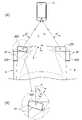
図1に示すように、遠隔駐車システム1は車両Sに搭載された車両システム2と、少なくとも1つの操作端末3とを含む。車両システム2は、推進装置4、ブレーキ装置5、ステアリング装置6、外界センサ7、車両センサ8、通信装置9、ナビゲーション装置10、運転操作装置11、HMI13、報知装置14、及び制御装置15を有している。車両システム2の各構成は、CAN16(Controller Area Network)等の通信手段によって信号伝達可能に互いに接続されている。 As shown in FIG. 1, theremote parking system 1 includes avehicle system 2 mounted on a vehicle S and at least oneoperation terminal 3. Thevehicle system 2 includes a propulsion device 4, abrake device 5, asteering device 6, an outside world sensor 7, avehicle sensor 8, acommunication device 9, anavigation device 10, a driving operation device 11, anHMI 13, anotification device 14, and acontrol device 15. is doing. Each configuration of thevehicle system 2 is connected to each other so that signals can be transmitted by a communication means such as CAN 16 (Control Area Network).

推進装置4は車両Sに駆動力を付与する装置であり、例えば動力源及び変速機を含む。動力源はガソリンエンジンやディーゼルエンジン等の内燃機関及び電動機の少なくとも一方を有する。ブレーキ装置5は車両Sに制動力を付与する装置であり、例えばブレーキロータにパッドを押し付けるブレーキキャリパと、ブレーキキャリパに油圧を供給する電動シリンダとを含む。ブレーキ装置5はワイヤケーブルによって車輪の回転を規制するパーキングブレーキ装置を含んでもよい。ステアリング装置6は車輪の舵角を変えるための装置であり、例えば車輪を転舵するラックアンドピニオン機構と、ラックアンドピニオン機構を駆動する電動モータとを有する。推進装置4、ブレーキ装置5、及びステアリング装置6は、制御装置15によって制御される。 The propulsion device 4 is a device that applies a driving force to the vehicle S, and includes, for example, a power source and a transmission. The power source has at least one of an internal combustion engine such as a gasoline engine and a diesel engine and an electric motor. Thebrake device 5 is a device that applies a braking force to the vehicle S, and includes, for example, a brake caliper that presses a pad against a brake rotor and an electric cylinder that supplies hydraulic pressure to the brake caliper. Thebrake device 5 may include a parking brake device that regulates the rotation of the wheels by a wire cable. Thesteering device 6 is a device for changing the steering angle of the wheels, and has, for example, a rack and pinion mechanism for steering the wheels and an electric motor for driving the rack and pinion mechanism. The propulsion device 4, thebrake device 5, and thesteering device 6 are controlled by thecontrol device 15.

外界センサ7は車両Sの周辺からの電磁波や音波等を捉えて、車外の物体等を検出するセンサである。外界センサ7はソナー17及び車外カメラ18を含んでいる。外界センサ7はミリ波レーダやレーザライダを含んでいてもよい。外界センサ7は検出結果を制御装置15に出力する。 The outside world sensor 7 is a sensor that detects an object or the like outside the vehicle by capturing electromagnetic waves, sound waves, or the like from the periphery of the vehicle S. The outside world sensor 7 includes asonar 17 and anoutside camera 18. The external sensor 7 may include a millimeter wave radar or a laser rider. The external sensor 7 outputs the detection result to thecontrol device 15.

ソナー17はいわゆる超音波センサであり、超音波を車両Sの周囲に発射し、その反射波を捉えることにより物体の位置(距離及び方向)を検出する。ソナー17は車両Sの後部及び前部にそれぞれ複数設けられている。本実施形態では、ソナー17はリアバンパに左右2対、フロントバンパに左右2対、車両Sの左右側面前端及び後端にそれぞれ1対ずつ、合計6対設けられている。 Thesonar 17 is a so-called ultrasonic sensor, which emits ultrasonic waves around the vehicle S and captures the reflected waves to detect the position (distance and direction) of the object. A plurality of sonar 17s are provided at the rear portion and the front portion of the vehicle S, respectively. In the present embodiment, thesonar 17 is provided with two pairs of left and right on the rear bumper, two pairs of left and right on the front bumper, and one pair on each of the front and rear ends of the left and right sides of the vehicle S, for a total of six pairs.

車外カメラ18は車両Sの周囲を撮像する装置であり、例えば、CCDやCMOS等の固体撮像素子を利用したデジタルカメラである。車外カメラ18は車両Sの前方を撮像する前方カメラと後方を撮像する後方カメラとを含んでいる。 The vehicleexterior camera 18 is a device that images the surroundings of the vehicle S, and is, for example, a digital camera that uses a solid-state image sensor such as a CCD or CMOS. The out-of-vehicle camera 18 includes a front camera that captures the front of the vehicle S and a rear camera that captures the rear.

車両センサ8は、車両Sの速度を検出する車速センサ、加速度を検出する加速度センサ、鉛直軸回りの角速度を検出するヨーレートセンサ、車両Sの向きを検出する方位センサ等を含む。ヨーレートセンサは、例えばジャイロセンサである。 Thevehicle sensor 8 includes a vehicle speed sensor that detects the speed of the vehicle S, an acceleration sensor that detects the acceleration, a yaw rate sensor that detects the angular velocity around the vertical axis, an orientation sensor that detects the direction of the vehicle S, and the like. The yaw rate sensor is, for example, a gyro sensor.

通信装置9は制御装置15と操作端末3との間の無線通信を媒介する装置である。制御装置15は通信装置9を介して、近距離無線通信規格であるBluetooth(登録商標)により、ユーザが所持する操作端末3と通信する。このように、Bluetooth(登録商標)により通信を行うように構成することによって、スマートフォンや携帯電話等の汎用の通信機器を操作端末3として利用することができる。 Thecommunication device 9 is a device that mediates wireless communication between thecontrol device 15 and theoperation terminal 3. Thecontrol device 15 communicates with theoperation terminal 3 owned by the user via thecommunication device 9 according to Bluetooth (registered trademark), which is a short-range wireless communication standard. As described above, by configuring the communication by Bluetooth (registered trademark), a general-purpose communication device such as a smartphone or a mobile phone can be used as theoperation terminal 3.

通信装置9は通信用アンテナ20(送信アンテナ)と、複数の測距用ユニット21(受信ユニット)とを含む。通信用アンテナ20は、制御装置15と操作端末3とのBluetooth(登録商標)に基づく無線(波長12cm)によるデータの送受信を媒介するための送受信アンテナであり、車体Bに固定されている。通信用アンテナ20が固定される場所は車室内であってもよく、また、エンジンルーム内であってもよい。 Thecommunication device 9 includes a communication antenna 20 (transmitting antenna) and a plurality of ranging units 21 (reception units). Thecommunication antenna 20 is a transmission / reception antenna for mediating data transmission / reception by radio (wavelength 12 cm) based on Bluetooth (registered trademark) between thecontrol device 15 and theoperation terminal 3, and is fixed to the vehicle body B. The place where thecommunication antenna 20 is fixed may be in the vehicle interior or in the engine room.

測距用ユニット21はユーザが保持する操作端末3からのBluetooth(登録商標)に基づく測距信号を受信して操作端末3から車両Sまでの距離を測定する(測距する)ための装置である。測距用ユニット21にはそれぞれIDとなるユニットIDが付与されている。測距信号は、例えば、BLE規格に基づくアドバタイズ信号であってもよい。但し、アドバタイズ信号とは、車両Sの遠隔駐車を実行することのできる操作端末3が自らの存在を周囲に通知して車両Sとの接続を確立するための信号である。 Thedistance measurement unit 21 is a device for receiving a distance measurement signal based on Bluetooth (registered trademark) from theoperation terminal 3 held by the user and measuring (measures the distance) the distance from theoperation terminal 3 to the vehicle S. be. A unit ID, which is an ID, is assigned to each of thedistance measuring units 21. The ranging signal may be, for example, an advertisement signal based on the BLE standard. However, the advertisement signal is a signal for theoperation terminal 3 capable of executing remote parking of the vehicle S to notify the surroundings of its existence and establish a connection with the vehicle S.

図2(A)に示すように、測距用ユニット21は、少なくとも車両S(車体B)左右前縁及び左右後縁にそれぞれ、車両S(車体B)の外縁に沿うように設けられている。これにより、測距用ユニット21が車両Sの前面のみや後面のみに設けられている場合に比べて、車両Sの前方又は後方に位置する操作端末3からの測距信号が受信可能となり、測距信号を安定して受信できるエリアをより広くすることができる。 As shown in FIG. 2A, thedistance measuring unit 21 is provided at least on the left and right leading edges and the left and right trailing edges of the vehicle S (vehicle body B) along the outer edges of the vehicle S (vehicle body B). .. As a result, the distance measuring signal can be received from theoperation terminal 3 located in front of or behind the vehicle S, as compared with the case where thedistance measuring unit 21 is provided only on the front surface or the rear surface of the vehicle S. It is possible to widen the area where the distance signal can be stably received.

本実施形態では、測距用ユニット21は車体Bの前面の左右両端と、車体後面の左右両端と、車体左側面の前後両端及び中央部と、車体Bの右側面の前後両端及び中央部とにそれぞれ設けられている。図2には、全ての測距用ユニット21が正常であるときに測距信号が安定して受信される領域が彩色されて示されている。以下、測距用ユニット21によって測距信号が安定して受信される領域を測距安定領域Zと記載する。 In the present embodiment, thedistance measuring unit 21 includes left and right ends on the front surface of the vehicle body B, left and right ends on the rear surface of the vehicle body, front and rear ends and the center portion on the left side surface of the vehicle body, and front and rear ends and the center portion on the right side surface of the vehicle body B. It is provided in each. FIG. 2 shows a colored region in which the ranging signal is stably received when all the rangingunits 21 are normal. Hereinafter, the region in which the ranging signal is stably received by the rangingunit 21 will be referred to as a ranging stable region Z.

図2にはユーザが車両Sの移動を監視可能となる領域(以下、監視可能領域X)の境界が実線で示されている。監視可能領域Xは、車両Sからの距離が距離閾値Dth以下となる領域として定義されている。本実施形態では距離閾値Dthは6mに設定されている。本発明においては、操作端末3はユーザの位置とは同じであると見做される。これにより、例えば、操作端末3が監視可能領域X内にあるときには、ユーザが車両Sの移動を監視可能であるとして、操作端末3による車両Sの移動が可能となる。In FIG. 2, the boundary of the region where the user can monitor the movement of the vehicle S (hereinafter, the monitorable region X) is shown by a solid line. The monitorable area X is defined as an area in which the distance from the vehicle S is equal to or less than the distance threshold valueDth . In this embodiment, the distance thresholdDth is set to 6 m. In the present invention, theoperation terminal 3 is considered to be the same as the position of the user. As a result, for example, when theoperation terminal 3 is in the monitorable area X, theoperation terminal 3 can move the vehicle S, assuming that the user can monitor the movement of the vehicle S.

全ての測距用ユニット21が正常であるときの測距安定領域Zは監視可能領域X内に位置し、且つ、概ねカバーするように設定されている。測距用ユニット21のいずれかが故障すると測距安定領域Zは全ての測距用ユニット21が正常であるときに比べて小さくなる。ユーザが操作端末3への操作入力を行って車両Sの移動を行うときには、ユーザ(すなわち操作端末3)は、測距安定領域Z内に位置することが望ましい。 The range-finding stable area Z when all the range-findingunits 21 are normal is located in the monitorable area X and is set to substantially cover the range-findingunit 21. If any of thedistance measuring units 21 fails, the distance measuring stable region Z becomes smaller than when all thedistance measuring units 21 are normal. When the user inputs an operation to theoperation terminal 3 to move the vehicle S, it is desirable that the user (that is, the operation terminal 3) is located in the range-finding stable region Z.

図3に示すように、測距用ユニット21は、板状の回路基板22と、回路基板22の表面に設けられた複数のアンテナ23と、通信IC24と、受信CPU25とを有している。 As shown in FIG. 3, thedistance measuring unit 21 includes a plate-shapedcircuit board 22, a plurality ofantennas 23 provided on the surface of thecircuit board 22, acommunication IC 24, and a receivingCPU 25.

回路基板22は数センチ角の板状のエポキシ樹脂等の絶縁体上に設けられた金属薄膜(本実施形態では銅箔)によって配線22Aが形成されたいわゆるプリント基板である。アンテナ23はプリント基板の表面に所定のパターン形状の金属薄膜(銅箔)が設けられることによって形成されている。アンテナ23の形状はそれぞれ、Bluetooth(登録商標)に基づく通信で用いられる2.4GHzの周波数帯域の電磁波を受信することができるように設計されている。これにより、アンテナ23によって測距信号が受信可能となっている。アンテナ23が回路基板22の表面に設けられることによって、回路基板22の表面は、測距信号を受信するための受信面22Sとなっている。 Thecircuit board 22 is a so-called printed circuit board in which thewiring 22A is formed by a metal thin film (copper foil in this embodiment) provided on an insulator such as a plate-shaped epoxy resin having a square shape of several centimeters. Theantenna 23 is formed by providing a metal thin film (copper foil) having a predetermined pattern on the surface of the printed circuit board. Each of theantennas 23 is designed to be able to receive electromagnetic waves in the 2.4 GHz frequency band used in communication based on Bluetooth®. As a result, the ranging signal can be received by theantenna 23. By providing theantenna 23 on the surface of thecircuit board 22, the surface of thecircuit board 22 is a receivingsurface 22S for receiving the ranging signal.

本実施形態では、回路基板22は略長方形状をなし、その短辺に沿って2つのアンテナ23が並ぶように配置されている。2つのアンテナ23の距離dは半波長以下の間隔(より具体的には、60mm以下)に設定されている。アンテナ23はそれぞれ略方形をなすように形成され、所定の配線22Aを介して通信IC24に接続されている。 In the present embodiment, thecircuit board 22 has a substantially rectangular shape, and the twoantennas 23 are arranged so as to be arranged along the short side thereof. The distance d between the twoantennas 23 is set to a distance of half a wavelength or less (more specifically, 60 mm or less). Each of theantennas 23 is formed so as to form a substantially rectangular shape, and is connected to thecommunication IC 24 via apredetermined wiring 22A.

測距用ユニット21はそれぞれ回路基板22の短辺が略水平となり、受信面22Sが車外側を向き、且つ各面で同じ高さとなるように車体Bに組み付けられて固定されている(図2(B)参照)。車体Bへの組付が完了したときには、測距用ユニット21はそれぞれ基準位置Pに基準姿勢で配置されている。但し、図2に示すように、基準位置Pは測地用ユニットの回路基板22の中心Gの車体Bの中心G(車長方向における中央、且つ、車幅方向における中央の位置)に対する位置を表す。本実施形態では、基準位置Pは車幅方向をx、車長方向をyとする座標系によって表されている。また、基準姿勢は工場出荷時の受信面22Sの向き(すなわち、取付方向の初期値)を示し、受信面22Sが前方を向く状態からの上下方向を軸線とし、右回りを正とする回転角度(以下、基準角度δ)によって表されている。基準位置Pはそれぞれ車体Bの外面上の位置に設定され、基準角度δは受信面22Sが車体外面に沿うように設定されている。Each of thedistance measuring units 21 is assembled and fixed to the vehicle body B so that the short side of thecircuit board 22 is substantially horizontal, the receivingsurface 22S faces the outside of the vehicle, and the height is the same on each surface (FIG. 2). (B)). When the assembly to the vehicle body B is completed, thedistance measuring units 21 are arranged at the reference position P in the reference posture. However, as shown in FIG. 2, the reference position P is the position of the center G of thecircuit board 22 of the geodetic unit with respect to the center G0 (the center in the vehicle length direction and the center in the vehicle width direction) of the vehicle body B. show. In the present embodiment, the reference position P is represented by a coordinate system in which the vehicle width direction is x and the vehicle length direction is y. The reference posture indicates the direction of the receivingsurface 22S at the time of shipment from the factory (that is, the initial value in the mounting direction), and the rotation angle with the vertical direction from the state where the receivingsurface 22S faces forward is the axis and the clockwise direction is positive. It is represented by (hereinafter, reference angle δ). The reference position P is set at a position on the outer surface of the vehicle body B, and the reference angle δ is set so that the receivingsurface 22S is along the outer surface of the vehicle body.

図2(A)に示すように、本実施形態では、車体Bの前面に位置する測距用ユニット21の基準角度δは0度、車体Bの後面に位置する測距用ユニット21の基準角度δは180度、車体右側面に位置する測距用ユニット21の基準角度δは90度、車体Bの左側面に位置する測距用ユニット21の基準角度δは270度にそれぞれ設定されている。これにより、測距用ユニット21はそれぞれ、受信面22Sが車外側を向き、概ね車体Bの外面に沿うように配置されている。 As shown in FIG. 2A, in the present embodiment, the reference angle δ of thedistance measuring unit 21 located on the front surface of the vehicle body B is 0 degrees, and the reference angle of thedistance measuring unit 21 located on the rear surface of the vehicle body B is 0 degrees. δ is set to 180 degrees, the reference angle δ of thedistance measuring unit 21 located on the right side surface of the vehicle body is set to 90 degrees, and the reference angle δ of thedistance measuring unit 21 located on the left side surface of the vehicle body B is set to 270 degrees. .. As a result, each of thedistance measuring units 21 is arranged so that the receivingsurface 22S faces the outside of the vehicle and substantially follows the outer surface of the vehicle body B.

また、車体前面左右両端に位置する測距用ユニット21は互いに前後に揃う位置に左右対称に配置されている。同様に、車体後面左右両端に位置する測距用ユニット21もまた互いに前後に揃う位置に左右対称に配置されている。更に、車体右側面に設けられた測距用ユニット21と、車体左側面に設けられた測距用ユニット21とは互いに左右対称な位置に配置されている。 Further, thedistance measuring units 21 located at the left and right ends of the front surface of the vehicle body are symmetrically arranged at positions aligned in the front-rear direction with each other. Similarly, thedistance measuring units 21 located at the left and right ends of the rear surface of the vehicle body are also symmetrically arranged at positions aligned with each other in the front-rear direction. Further, thedistance measuring unit 21 provided on the right side surface of the vehicle body and thedistance measuring unit 21 provided on the left side surface of the vehicle body are arranged at positions symmetrical with each other.

通信IC24は集積回路を含む半導体チップである。通信IC24は回路基板22の表面に半田付けされ、回路基板22上の配線22Aを介して回路基板22上の複数(本実施形態では2つ)のz23と、受信CPU25とに接続されている。通信IC24はアンテナ23が受信した信号をアンテナ23からそれぞれ取得し、信号の電圧変動の態様や信号の時間差に基づいて、取得した信号間の位相差を受信CPU25に出力する。本実施形態では、通信IC24はグランド(例えば、車体等)に対するアンテナ23の電位(以下、電圧)をそれぞれ取得し、各アンテナ23の電圧の時間変動に基づいて、アンテナ23によって取得された信号(電圧)の位相差を算出する。 Thecommunication IC 24 is a semiconductor chip including an integrated circuit. Thecommunication IC 24 is soldered to the surface of thecircuit board 22, and is connected to a plurality of (two in this embodiment) z23 on thecircuit board 22 and the receivingCPU 25 via thewiring 22A on thecircuit board 22. Thecommunication IC 24 acquires the signal received by theantenna 23 from theantenna 23, and outputs the phase difference between the acquired signals to the receivingCPU 25 based on the mode of the voltage fluctuation of the signal and the time difference of the signal. In the present embodiment, thecommunication IC 24 acquires the potential (hereinafter, voltage) of theantenna 23 with respect to the ground (for example, the vehicle body or the like), and the signal acquired by the antenna 23 (hereinafter, voltage) based on the time variation of the voltage of each antenna 23 (hereinafter, voltage). Calculate the phase difference of voltage).

図4(A)に示すように、受信面22Sに上面視で垂直に操作端末3から測距信号が送信された場合には、2つのアンテナ23a、23bの電圧Va及びVbはそれぞれ正弦波状に変化し、図4(B)に示すように両者の位相差は0となる。一方、図5(A)に示すように、受信面22Sの垂線に対して上面視で45度の角度をなすように操作端末3から測距信号が送信された場合には、2つのアンテナ23a、23bの電圧Va及びVbもまた正弦波状に変化し、図5(B)に示すように両者に位相差が生じる。 As shown in FIG. 4A, when the distance measuring signal is transmitted vertically from theoperation terminal 3 to the receivingsurface 22S in a top view, the voltages Va and Vb of the twoantennas 23a and 23b are sinusoidal, respectively. It changes, and the phase difference between the two becomes 0 as shown in FIG. 4 (B). On the other hand, as shown in FIG. 5A, when the distance measuring signal is transmitted from theoperation terminal 3 so as to form an angle of 45 degrees in top view with respect to the perpendicular line of the receivingsurface 22S, the twoantennas 23a , 23b, the voltages Va and Vb also change in a sine wave shape, and a phase difference occurs between them as shown in FIG. 5 (B).

受信CPU25はいわゆる中央演算処理装置であって、通信IC24によって出力された位相差に基づいて、受信面22Sを基準とする測距信号の到来方向を取得する。ここでいう到来方向とは、測距信号の入射方向と受信面22Sの法線とがなす角度、すなわち入射角度に相当するものであって、上面視で2つのアンテナ23の中心から受信面22Sに垂直に離れる方向に延びる直線(以下、基準線)と、測距信号の伝播方向とのなす角度(以下、到来角度θ。図6(B)を参照)によって表される。但し、到来角度θは上面視で右回りを正(すなわち、図6(B)において、到来角度θ>0)となるように定められている。 The receivingCPU 25 is a so-called central processing unit, and acquires the arrival direction of the ranging signal with respect to the receivingsurface 22S based on the phase difference output by thecommunication IC 24. The arrival direction here corresponds to the angle formed by the incident direction of the ranging signal and the normal line of the receivingsurface 22S, that is, the incident angle, and is seen from the center of the twoantennas 23 to the receivingsurface 22S. It is represented by an angle formed by a straight line extending in a direction perpendicular to the direction (hereinafter referred to as a reference line) and a propagation direction of a ranging signal (hereinafter referred to as an arrival angle θ; see FIG. 6B). However, the arrival angle θ is set so that the clockwise direction is positive (that is, the arrival angle θ> 0 in FIG. 6B) in the top view.

操作端末3が測距信号を発している場合には、測距信号の到来方向は、受信面22Sに対する測距信号の発生源、すなわち操作端末3の方向に等しくなる。よって、操作端末3が測距信号を発している場合には、受信CPU25は測距信号の到来方向を取得することによって、受信面22Sに対する操作端末3の方向を取得することができる。 When theoperation terminal 3 emits a distance measurement signal, the direction of arrival of the distance measurement signal is equal to the direction of the source of the distance measurement signal with respect to the receivingsurface 22S, that is, the direction of theoperation terminal 3. Therefore, when theoperation terminal 3 emits the distance measurement signal, the receivingCPU 25 can acquire the direction of theoperation terminal 3 with respect to thereception surface 22S by acquiring the arrival direction of the distance measurement signal.

より具体的には、例えば、アンテナ23間の距離がセンサと操作端末3との距離に比べて十分小さく、アンテナ23において受信される測距信号は平面波と見做すことができる場合には、アンテナ23間の距離をd[mm]、測距信号の波長をλ[mm]、アンテナ23間の位相差をφ[rad]とすると、到来角度θはθ=sin-1(φλ/d)によって算出することができる。More specifically, for example, when the distance between theantennas 23 is sufficiently smaller than the distance between the sensor and theoperation terminal 3, and the range-finding signal received by theantenna 23 can be regarded as a plane wave, it is possible. Assuming that the distance between theantennas 23 is d [mm], the wavelength of the ranging signal is λ [mm], and the phase difference between theantennas 23 is φ [rad], the arrival angle θ is θ = sin-1 (φλ / d). Can be calculated by.

受信CPU25はそれぞれ測距信号を受信すると、到来角度θと、その信号の受信強度Iとを制御装置15に出力する。 When the receivingCPU 25 receives the distance measuring signal, the receivingCPU 25 outputs the arrival angle θ and the reception intensity I of the signal to thecontrol device 15.

図1に示すように、ナビゲーション装置10は車両Sの現在位置を取得し、目的地への経路案内等を行う装置であり、GPS受信部26、及び地図記憶部27を有する。GPS受信部26は人工衛星(測位衛星)から受信した信号に基づいて車両Sの位置(緯度や経度)を特定する。地図記憶部27は、フラッシュメモリやハードディスク等の公知の記憶装置によって構成され、地図情報を記憶している。 As shown in FIG. 1, thenavigation device 10 is a device that acquires the current position of the vehicle S and provides route guidance to a destination, and has aGPS receiving unit 26 and amap storage unit 27. TheGPS receiving unit 26 identifies the position (latitude and longitude) of the vehicle S based on the signal received from the artificial satellite (positioning satellite). Themap storage unit 27 is configured by a known storage device such as a flash memory or a hard disk, and stores map information.

運転操作装置11は車室内に設けられ、車両Sを制御するためにユーザが行う入力操作を受け付ける。運転操作装置11は、ステアリングホイール、アクセルペダル、ブレーキペダル、シフトレバー、及び、プッシュスタートスイッチ(エンジンスタートボタン)を含む。プッシュスタートスイッチはユーザから車両Sを起動するための入力操作を受け付ける。運転操作装置11は更に、パーキングブレーキ装置を含んでいてもよい。 The driving operation device 11 is provided in the vehicle interior and receives an input operation performed by the user to control the vehicle S. The driving operation device 11 includes a steering wheel, an accelerator pedal, a brake pedal, a shift lever, and a push start switch (engine start button). The push start switch accepts an input operation for starting the vehicle S from the user. The driving operation device 11 may further include a parking brake device.

HMI13は、ユーザに対して表示や音声によって各種情報を報知すると共に、ユーザによる入力操作を受け付ける。HMI13は、例えば、液晶や有機EL等を含み、ユーザからの入力操作を受け付けるタッチパネル28と、ブザーやスピーカ等の音発生装置29とを含む。 TheHMI 13 notifies the user of various information by display or voice, and accepts an input operation by the user. TheHMI 13 includes, for example, a liquid crystal display, an organic EL, and the like, and includes atouch panel 28 that accepts an input operation from a user, and asound generator 29 such as a buzzer and a speaker.

報知装置14は車外に居るユーザに光及び音の少なくとも一方によって報知を行うための装置であって、本実施形態では、車両Sの前方を照らす前照灯30(灯具)と、車外に警告音を発するホーン31(音響装置)とを含む。報知装置14は制御装置15からの信号に基づいて作動する。より具体的には、前照灯30は制御装置15からの信号に基づいて点滅し、ホーン31は制御装置15からの信号に基づいて車外に警告音を発する。 Thenotification device 14 is a device for notifying a user outside the vehicle by at least one of light and sound, and in the present embodiment, a headlight 30 (lighting tool) that illuminates the front of the vehicle S and a warning sound outside the vehicle. Includes a horn 31 (acoustic device) that emits light. Thenotification device 14 operates based on the signal from thecontrol device 15. More specifically, theheadlight 30 blinks based on the signal from thecontrol device 15, and thehorn 31 emits a warning sound to the outside of the vehicle based on the signal from thecontrol device 15.

制御装置15は、CPU、不揮発性メモリ(ROM)、及び、揮発性メモリ(RAM)等を含む電子制御装置(ECU)である。制御装置15はCPUでプログラムに沿った演算処理を実行することで、各種の車両制御を実行する。制御装置15は1つのハードウェアとして構成されていてもよく、複数のハードウェアからなるユニットとして構成されていてもよい。また、制御装置15の各機能部の少なくとも一部は、LSIやASIC、FPGA等のハードウェアによって実現されてもよく、ソフトウェア及びハードウェアの組み合わせによって実現されてもよい。 Thecontrol device 15 is an electronic control device (ECU) including a CPU, a non-volatile memory (ROM), a volatile memory (RAM), and the like. Thecontrol device 15 executes various vehicle controls by executing arithmetic processing according to the program by the CPU. Thecontrol device 15 may be configured as one hardware, or may be configured as a unit composed of a plurality of hardware. Further, at least a part of each functional unit of thecontrol device 15 may be realized by hardware such as LSI, ASIC, FPGA, or may be realized by a combination of software and hardware.

操作端末3はユーザが携帯可能な無線端末であり、車外から通信装置9を介して制御装置15と相互に通信可能である。本実施形態では、操作端末3はスマートフォンである。
操作端末3には予め所定のアプリケーションがインストールされることによって、制御装置15と通信可能となっている。
Theoperation terminal 3 is a wireless terminal that can be carried by the user, and can communicate with thecontrol device 15 from outside the vehicle via thecommunication device 9. In this embodiment, theoperation terminal 3 is a smartphone.
By installing a predetermined application in advance on theoperation terminal 3, it is possible to communicate with thecontrol device 15.

操作端末3は出入力部32、位置検出部33、通信部34、及び処理部35を備えている。 Theoperation terminal 3 includes an input /output unit 32, aposition detection unit 33, acommunication unit 34, and aprocessing unit 35.

出入力部32は操作端末3を操作するユーザに情報を提示すると共に、操作端末3を操作するユーザからの入力を受け付ける。出入力部32は例えばタッチパネルである。出入力部32はユーザからの入力を受け付けると、入力に対応する信号を処理部35に出力する。 The input /output unit 32 presents information to the user who operates theoperation terminal 3 and accepts input from the user who operates theoperation terminal 3. The input /output unit 32 is, for example, a touch panel. When the input /output unit 32 receives an input from the user, the input /output unit 32 outputs a signal corresponding to the input to theprocessing unit 35.

位置検出部33は操作端末3の位置情報を取得する。位置検出部33は例えば測地衛星(GPS衛星)からの信号を受信することにより操作端末3の位置を取得するとよい。位置検出部33は取得した位置情報を処理部35に出力する。 Theposition detection unit 33 acquires the position information of theoperation terminal 3. Theposition detection unit 33 may acquire the position of theoperation terminal 3 by receiving, for example, a signal from a geodetic satellite (GPS satellite). Theposition detection unit 33 outputs the acquired position information to theprocessing unit 35.

通信部34は操作端末3と制御装置15との通信を媒介する。通信部34は処理部35からの信号に基づいて、Bluetooth(登録商標)の規格に適合する周波数帯の無線信号を外部に送受信するためのアンテナを含む。 Thecommunication unit 34 mediates communication between theoperation terminal 3 and thecontrol device 15. Thecommunication unit 34 includes an antenna for transmitting and receiving a radio signal in a frequency band conforming to the Bluetooth (registered trademark) standard to the outside based on the signal from theprocessing unit 35.

処理部35はユーザの出入力部32への入力、通信部34において受信した信号、及び制御装置15からの信号に基づいてアプリケーションに対応する処理を行う。また、処理部35は処理の結果を適宜、出入力部32に表示するとともに、適宜、通信部34を制御して外部に無線信号を送信させる。より具体的には、出入力部32に車両Sを遠隔操作するためのアプリケーションの起動を指示する入力が行われると、処理部35は通信部34を制御し、測距信号(より詳細にはアドバタイズ信号)を一定の時間間隔毎に発信させる。 Theprocessing unit 35 performs processing corresponding to the application based on the input to the input /output unit 32 of the user, the signal received by thecommunication unit 34, and the signal from thecontrol device 15. Further, theprocessing unit 35 appropriately displays the processing result on the input /output unit 32, and appropriately controls thecommunication unit 34 to transmit a wireless signal to the outside. More specifically, when an input instructing the input /output unit 32 to start an application for remotely controlling the vehicle S is performed, theprocessing unit 35 controls thecommunication unit 34 and a distance measuring signal (more specifically,). Advertisement signal) is transmitted at regular time intervals.

制御装置15は少なくとも2つの測距用ユニット21に異常がなく測距可能であり、且つ、操作端末3が監視可能領域X内に位置するときに、操作端末3への操作入力に基づいて車両Sを制御し、所定の位置に移動させて駐車させる、いわゆる遠隔駐車を実行する。このような車両Sの制御を行うため、制御装置15は、外界認識部41、自車位置特定部42、行動計画部43、走行制御部44及び記憶部45を有する。 Thecontrol device 15 can measure distance without any abnormality in at least twodistance measuring units 21, and when theoperation terminal 3 is located in the monitorable area X, the vehicle is based on the operation input to theoperation terminal 3. The so-called remote parking, in which S is controlled and moved to a predetermined position to be parked, is executed. In order to control the vehicle S in this way, thecontrol device 15 has an outsideworld recognition unit 41, a vehicleposition specifying unit 42, anaction planning unit 43, a travelingcontrol unit 44, and astorage unit 45.

外界認識部41は、外界センサ7の検出結果に基づいて、車両Sの周辺に存在する物体、例えば、駐車車両や壁などの障害物を認識し、障害物に関する位置や大きさ等の情報を取得する。また、外界認識部41は車外カメラ18によって取得した画像をパターンマッチング等の公知の画像解析手法に基づいて解析し、障害物の有無及びその大きさを取得する。更に、外界認識部41はソナー17からの信号を用いて障害物までの距離を算出し、障害物の位置を取得するとよい。 The outsideworld recognition unit 41 recognizes an object existing around the vehicle S, for example, an obstacle such as a parked vehicle or a wall, based on the detection result of the outside world sensor 7, and obtains information such as the position and size of the obstacle. get. Further, the outsideworld recognition unit 41 analyzes the image acquired by the vehicle outsidecamera 18 based on a known image analysis method such as pattern matching, and acquires the presence / absence of an obstacle and its size. Further, the outsideworld recognition unit 41 may calculate the distance to the obstacle using the signal from thesonar 17 and acquire the position of the obstacle.

自車位置特定部42は、ナビゲーション装置10のGPS受信部26からの信号に基づいて、車両Sの位置を検出する。また、自車位置特定部42はGPS受信部26からの信号に加えて、車両センサ8から車速やヨーレートを取得し、いわゆる慣性航法を用いて車両Sの位置及び姿勢を特定してもよい。 The own vehicleposition specifying unit 42 detects the position of the vehicle S based on the signal from theGPS receiving unit 26 of thenavigation device 10. Further, the own vehicleposition specifying unit 42 may acquire the vehicle speed and yaw rate from thevehicle sensor 8 in addition to the signal from theGPS receiving unit 26, and specify the position and attitude of the vehicle S by using so-called inertial navigation.

外界認識部41は、外界センサ7の検出結果、より具体的には車外カメラ18によって撮像された画像をパターンマッチング等の公知の画像解析手法に基づいて解析し、例えば、駐車場等の路面に描かれた白線の位置を取得することができる。 The outsideworld recognition unit 41 analyzes the detection result of the outside world sensor 7, more specifically, the image captured by theoutside camera 18 based on a known image analysis method such as pattern matching, and for example, on a road surface such as a parking lot. You can get the position of the drawn white line.

走行制御部44は、行動計画部43からの走行制御の指示に基づいて、推進装置4、ブレーキ装置5、及びステアリング装置6を制御し、車両Sを走行させる。 Thetravel control unit 44 controls the propulsion device 4, thebrake device 5, and thesteering device 6 based on the instruction of the travel control from theaction planning unit 43, and causes the vehicle S to travel.

記憶部45はRAM等によって構成され、行動計画部43、及び走行制御部44の処理に要する情報が記憶されている。 Thestorage unit 45 is composed of a RAM or the like, and stores information required for processing of theaction planning unit 43 and thetravel control unit 44.

記憶部45は少なくとも、車体Bに設けられた測距用ユニット21それぞれのユニットIDと、対応する基準位置Pと、対応する基準角度δとを関連付けて、基準テーブル(図7(A)参照)として記憶している。更に、記憶部45は車体Bの外面形状に係る情報(以下、外面形状情報)を記憶している。 Thestorage unit 45 associates at least the unit ID of each of thedistance measuring units 21 provided in the vehicle body B with the corresponding reference position P and the corresponding reference angle δ, and associates the reference table (see FIG. 7A). I remember as. Further, thestorage unit 45 stores information related to the outer surface shape of the vehicle body B (hereinafter, outer surface shape information).

記憶部45は更に、測距用ユニット21の車体B組付完了後、工場出荷前に、通信用アンテナ20から所定強度の測距用信号(以下、テスト信号)を発信した場合に、測距用ユニット21それぞれにおいて受信されるテスト信号の到来角度θを初期角度φ、その強度を初期強度I0として、ユニットIDを関連付けて基準テーブルに記憶している。初期角度φ及び初期強度I0はそれぞれ通信用アンテナ20を組み付けた後、出荷前の実車試験によって取得されたものであってもよく、また、シミュレーションによって算出されたものであってもよい。Further, thestorage unit 45 further transmits a distance measuring signal (hereinafter referred to as a test signal) having a predetermined strength from thecommunication antenna 20 after the assembly of the body B of thedistance measuring unit 21 is completed and before the factory shipment. The arrival angle θ of the test signal received in each of theunits 21 is set as the initial angle φ, and the strength thereof is set as the initial strength I0 , and the unit IDs are associated and stored in the reference table. The initial angle φ and the initial strength I0 may be those acquired by the actual vehicle test before shipment after assembling thecommunication antenna 20, respectively, or may be those calculated by simulation.

行動計画部43はHMI13や操作端末3へのユーザからの入力があると、必要に応じて、車両Sの走行経路となる軌道を算出して、走行制御部44に走行制御の指示を出力する。 When theaction planning unit 43 receives an input from the user to theHMI 13 or theoperation terminal 3, theaction planning unit 43 calculates a track to be a traveling route of the vehicle S as necessary, and outputs a traveling control instruction to the travelingcontrol unit 44. ..

<<駐車アシスト処理>>
行動計画部43は車両Sが停止された後、ユーザから遠隔操作による駐車アシストを希望することに対応する入力があったときに、駐車アシスト処理を行う。以下では、駐車アシスト処理について図8のタイムチャートを参照して説明を行う。
<< Parking Assist Processing >>
After the vehicle S is stopped, theaction planning unit 43 performs the parking assist process when the user inputs a request for parking assist by remote control. Hereinafter, the parking assist process will be described with reference to the time chart of FIG.

行動計画部43は最初に駐車可能位置の取得を行う取得処理を行う。より具体的には、行動計画部43はまず、HMI13のタッチパネル28に運転を行うユーザに車両Sを直進させるように指示する通知を表示させる。運転を行うユーザが車両Sを直進させている間に、行動計画部43は外界センサ7からの信号に基づいて、障害物の位置及び大きさと、路面に描かれた白線の位置とを取得する。行動計画部43は取得した障害物の位置及び大きさと白線とに基づいて、駐車可能なスペース(以下、駐車可能位置)を抽出する。 Theaction planning unit 43 first performs an acquisition process for acquiring a parkingable position. More specifically, theaction planning unit 43 first causes thetouch panel 28 of theHMI 13 to display a notification instructing the driving user to drive the vehicle S straight. While the driving user is moving the vehicle S straight, theaction planning unit 43 acquires the position and size of the obstacle and the position of the white line drawn on the road surface based on the signal from the outside world sensor 7. .. Theaction planning unit 43 extracts a parkable space (hereinafter referred to as a parkable position) based on the acquired position and size of the obstacle and the white line.

次に、行動計画部43は駐車可能位置から駐車位置を受け付ける駐車位置受付処理を行う。より具体的には、行動計画部43は駐車可能位置を少なくとも1つ取得すると、行動計画部43は運転を行うユーザに車両Sを停止させるように指示する通知をタッチパネル28に表示させる。このとき、行動計画部43は運転を行うユーザに車両Sを停止させた後、シフトレバーをパーキングポジションに変更するように指示してもよい。 Next, theaction planning unit 43 performs a parking position reception process for accepting a parking position from a parkingable position. More specifically, when theaction planning unit 43 acquires at least one parkable position, theaction planning unit 43 causes thetouch panel 28 to display a notification instructing the driving user to stop the vehicle S. At this time, theaction planning unit 43 may instruct the driving user to change the shift lever to the parking position after stopping the vehicle S.

行動計画部43はタッチパネル28に車両Sの現在地と、駐車可能位置とを表示する。このとき、行動計画部43はタッチパネル28に車外カメラ18によって取得した画像を重ねて表示させるとよい。その後、行動計画部43はタッチパネル28に、ユーザに駐車可能位置の中から車両Sを駐車させる位置(駐車位置)として1つを選択するよう通知する表示を行う。ユーザから希望する駐車位置が入力されると、タッチパネル28は入力された駐車位置に対応する信号を行動計画部43に出力する。 Theaction planning unit 43 displays the current location of the vehicle S and the parkingable position on thetouch panel 28. At this time, theaction planning unit 43 may superimpose and display the image acquired by the vehicle outsidecamera 18 on thetouch panel 28. After that, theaction planning unit 43 displays on thetouch panel 28 notifying the user to select one as the position (parking position) for parking the vehicle S from the parkable positions. When the desired parking position is input from the user, thetouch panel 28 outputs a signal corresponding to the input parking position to theaction planning unit 43.

次に、行動計画部43はタッチパネル28からユーザによって入力された駐車位置を受信すると、車両Sの現在地から駐車位置に至るまでの車両Sの軌道を算出する軌道算出処理を行う。前向き駐車及び後向き駐車の選択に関するユーザの入力操作を受け付けたときに、行動計画部43は車両Sの現在地及び駐車位置に加え、ユーザからの入力に基づいて軌道を算出するとよい。 Next, when theaction planning unit 43 receives the parking position input by the user from thetouch panel 28, theaction planning unit 43 performs a track calculation process for calculating the track of the vehicle S from the current location of the vehicle S to the parking position. When the user's input operation regarding the selection of forward parking and backward parking is accepted, theaction planning unit 43 may calculate the trajectory based on the input from the user in addition to the current location and parking position of the vehicle S.

軌道の算出が終わると、行動計画部43はタッチパネル28にユーザに降車を促す通知を行うと共に、ユーザに操作端末3の遠隔駐車のためのアプリケーションを起動するよう指示する通知を表示させる。これらの通知に従って、ユーザは降車した後、操作端末3のアプリケーションを起動させる。 When the calculation of the trajectory is completed, theaction planning unit 43 notifies thetouch panel 28 to urge the user to disembark, and displays a notification instructing the user to start the application for remote parking of theoperation terminal 3. According to these notifications, the user activates the application of theoperation terminal 3 after getting off.

その後、操作端末3の出入力部32には、車両Sへの接続実行を行うための入力ボタンが表示される。ユーザが入力ボタンにタッチすると、操作端末3は、処理部35は通信部34から一定の時間間隔毎に測距信号(すなわち、アドバタイズ信号)を発信させる。行動計画部43が通信用アンテナ20において測距信号を受信すると、操作端末3と相互に通信を行って、操作端末3を認証する認証処理を行う。操作端末3の認証が完了すると、行動計画部43は較正処理を行う。より具体的には、較正処理には、測距に必要な少なくとも2つ以上の測距用ユニット21に異常がなく遠隔駐車が実施可能であるかを判定する処理と、測距用ユニット21によって検出される到来角度θを、測距用ユニット21が工場出荷時の状態、すなわち基準姿勢にあるとした場合に検出されるべき到来角度θ(到来角度補正値θ)に補正するための補正角度εを取得する処理とが含まれる。較正処理の詳細については別途後述する。After that, the input /output unit 32 of theoperation terminal 3 displays an input button for executing the connection to the vehicle S. When the user touches the input button, theoperation terminal 3 causes theprocessing unit 35 to transmit a distance measurement signal (that is, an advertisement signal) from thecommunication unit 34 at regular time intervals. When theaction planning unit 43 receives the ranging signal at thecommunication antenna 20, it communicates with theoperation terminal 3 and performs an authentication process for authenticating theoperation terminal 3. When the authentication of theoperation terminal 3 is completed, theaction planning unit 43 performs the calibration process. More specifically, the calibration process includes a process of determining whether at least two or more range-findingunits 21 required for range-finding are normal and remote parking is possible, and a range-findingunit 21. Correction to correct the detected arrival angle θ to the arrival angle θ (arrival angle correction value θ* ) that should be detected when the rangingunit 21 is in the factory default state, that is, in the reference posture. It includes the process of acquiring the angle ε. The details of the calibration process will be described later.

遠隔駐車が実施可能である場合には、行動計画部43は操作端末3に車両Sの現在地、軌道、及び駐車位置を含む開始信号を送信する。操作端末3は開始信号を受信すると、出入力部32に、車両Sの現在地、軌道、及び駐車位置に対応する表示を行う。このとき、操作端末3は同時に出入力部32に上下方向を向く両矢印を表示させ、ユーザに上方向(又は下方向)へのスワイプによって出入力部32に操作入力が可能であることを通知するとよい。その後、ユーザはスワイプ操作によって操作端末3に操作入力を行うことにより、行動計画部43に遠隔駐車処理(リモート駐車処理)の実行を指示することができる。遠隔駐車処理には、車両Sを駐車位置に移動させる移動処理と、車両Sを駐車位置に駐車させる駐車処理とが含まれる。 When remote parking is possible, theaction planning unit 43 transmits a start signal including the current location, track, and parking position of the vehicle S to theoperation terminal 3. When theoperation terminal 3 receives the start signal, theoperation terminal 3 displays on the input /output unit 32 corresponding to the current location, the track, and the parking position of the vehicle S. At this time, theoperation terminal 3 simultaneously displays a double-headed arrow pointing in the vertical direction on the input /output unit 32, and notifies the user that the input /output unit 32 can input the operation by swiping upward (or downward). It is good to do it. After that, the user can instruct theaction planning unit 43 to execute the remote parking process (remote parking process) by inputting an operation to theoperation terminal 3 by swiping. The remote parking process includes a movement process for moving the vehicle S to the parking position and a parking process for parking the vehicle S at the parking position.

遠隔駐車が実施可能でない場合には、行動計画部43は操作端末3に測距用ユニット21の異常、(すなわち測距用ユニット21の故障)を通知させるべく信号(故障通知信号)を送信する。これにより、操作端末3の出入力部32にはユーザに測距用ユニット21の異常を通知する表示が行われる。このとき、行動計画部43は記憶部45から、異常が確認された測距用ユニット21のセンサIDと、対応する基準位置Pとを取得し、これらを故障通知信号に含めて、操作端末3に送信するとよい。操作端末3は異常が確認された測距用ユニット21のセンサIDと、対応する基準位置Pとを取得すると、測距用ユニット21の異常を通知するとともに、故障が確認された測距用ユニット21の位置を出入力部32(タッチパネル)に表示するとよい。表示が完了すると、行動計画部43は駐車アシスト処理を終了する。 When remote parking is not feasible, theaction planning unit 43 transmits a signal (fault notification signal) to notify theoperation terminal 3 of an abnormality in the distance measuring unit 21 (that is, a failure of the distance measuring unit 21). .. As a result, the input /output unit 32 of theoperation terminal 3 is displayed to notify the user of the abnormality of thedistance measuring unit 21. At this time, theaction planning unit 43 acquires the sensor ID of thedistance measuring unit 21 in which the abnormality is confirmed and the corresponding reference position P from thestorage unit 45, includes these in the failure notification signal, and includes theoperation terminal 3 You should send it to. When theoperation terminal 3 acquires the sensor ID of thedistance measuring unit 21 in which the abnormality is confirmed and the corresponding reference position P, theoperation terminal 3 notifies the abnormality of thedistance measuring unit 21 and the distance measuring unit in which the failure is confirmed. The position of 21 may be displayed on the input / output unit 32 (touch panel). When the display is completed, theaction planning unit 43 ends the parking assist process.

故障した測距用ユニット21の位置が出入力部32に表示されることで、ユーザが故障した測距用ユニット21の位置を把握することができる。これにより、故障した測距用ユニット21の修理や交換がし易くなる。 By displaying the position of the faileddistance measuring unit 21 on the input /output unit 32, the user can grasp the position of the faileddistance measuring unit 21. This facilitates repair or replacement of the failed rangingunit 21.

遠隔駐車が実施可能であると判定されると、操作端末3の出入力部32には車両Sの現在地、軌道、及び駐車位置と、上下方向を向く両矢印が表示される。その後、車両Sが駐車位置に移動するまで、行動計画部43は所定時間毎に絶えず、端末位置判定処理を行って、ユーザが車両Sの移動を監視可能であるか否かを判定する。より具体的には、操作端末3が車両Sまでの距離が距離閾値Dth以下の領域(すなわち、監視可能領域X)内に位置しているときには、ユーザが車両Sの移動を監視可能であると判定し、それ以外の場合にはユーザが車両Sの移動を監視可能でないと判定する。行動計画部43はユーザが車両Sの移動を監視できないと判定したときには、車両Sの移動を禁止する。このとき、車両Sが移動している場合には、行動計画部43は車両Sを停止させる。その後、行動計画部43は操作端末3から車両Sまでの距離が距離閾値Dth以下となるまで待機する。また、行動計画部43は端末位置判定処理中において操作端末3から車両Sまでの距離と、車両Sに対する(車両Sから見た)操作端末3の方向とを取得する。When it is determined that remote parking is possible, the input /output unit 32 of theoperation terminal 3 displays the current location, track, and parking position of the vehicle S, and double-headed arrows pointing in the vertical direction. After that, until the vehicle S moves to the parking position, theaction planning unit 43 constantly performs the terminal position determination process at predetermined time intervals to determine whether or not the user can monitor the movement of the vehicle S. More specifically, when theoperation terminal 3 is located within the region where the distance to the vehicle S is equal to or less than the distance thresholdDth (that is, the monitorable region X), the user can monitor the movement of the vehicle S. In other cases, it is determined that the user cannot monitor the movement of the vehicle S. When theaction planning unit 43 determines that the movement of the vehicle S cannot be monitored, theaction planning unit 43 prohibits the movement of the vehicle S. At this time, if the vehicle S is moving, theaction planning unit 43 stops the vehicle S. After that, theaction planning unit 43 waits until the distance from theoperation terminal 3 to the vehicle S becomes equal to or less than the distance threshold valueDth . Further, theaction planning unit 43 acquires the distance from theoperation terminal 3 to the vehicle S and the direction of the operation terminal 3 (as seen from the vehicle S) with respect to the vehicle S during the terminal position determination process.

ユーザが、出入力部32に表示された上下方向を向く両矢印に沿ってスワイプすることによって操作入力を行うと、操作端末3はスワイプ量に応じた操作量信号を行動計画部43に送信する。 When the user inputs an operation by swiping along a double-headed arrow pointing in the vertical direction displayed on the input /output unit 32, theoperation terminal 3 transmits an operation amount signal according to the swipe amount to theaction planning unit 43. ..

操作端末3が車両Sまでの距離が距離閾値Dth以下の領域、すなわち監視可能領域X内にあるときに通信用アンテナ20が操作量信号を受信すると、行動計画部43は操作量信号を車両Sの移動距離に換算する。但し、上記したように、操作端末3が車両Sまでの距離が距離閾値Dth以下の領域、すなわち監視可能領域X外にあるときに操作量信号を受信した場合には、行動計画部43は車両Sの移動を禁止し、操作端末3から車両Sまでの距離が距離閾値Dth以下となるまで待機する。When thecommunication antenna 20 receives the operation amount signal when theoperation terminal 3 is in the area where the distance to the vehicle S is equal to or less than the distance thresholdDth , that is, within the monitorable area X, theaction planning unit 43 transmits the operation amount signal to the vehicle. Convert to the moving distance of S. However, as described above, when theoperation terminal 3 receives the operation amount signal when the distance to the vehicle S is equal to or less than the distance threshold valueDth , that is, outside the monitorable area X, theaction planning unit 43 causes theaction planning unit 43. The movement of the vehicle S is prohibited, and the device waits until the distance from theoperation terminal 3 to the vehicle S becomes equal to or less than the distance threshold valueDth .

行動計画部43は車両Sの移動距離の換算が完了すると、行動計画部43は車両Sの現在地と軌道とに基づいて車両Sの移動すべき方向(以下、進行方向)を算出する。行動計画部43は更に、移動距離だけ軌道に沿って移動させた場合の推定位置を算出する。 When the conversion of the moving distance of the vehicle S is completed, theaction planning unit 43 calculates the direction in which the vehicle S should move (hereinafter referred to as the traveling direction) based on the current location and the track of the vehicle S. Theaction planning unit 43 further calculates an estimated position when the vehicle is moved along the trajectory by the movement distance.

次に、行動計画部43は操作端末3から車両Sまでの距離、車両Sに対する操作端末3の方向、移動距離、及び進行方向に基づいて、操作端末3が車両Sの進行方向にあり、且つ、操作端末3から車両Sまでの距離が移動距離以下であるかを判定する。操作端末3が車両Sの進行方向にあり、且つ、操作端末3から車両Sまでの距離が移動距離以下である場合には、行動計画部43は車両Sを停止させ、その後、操作端末3に警告信号を送信する。操作端末3は警告信号を受信すると、出入力部32にユーザの退避を促す通知を行う。これにより、車両Sが操作端末3を保持するユーザに接触することが防止でき、車両Sの安全性が高められる。端末に警告が表示されることによって、ユーザは退避すべきことを容易に認識することができる。 Next, theaction planning unit 43 has theoperation terminal 3 in the traveling direction of the vehicle S based on the distance from the operatingterminal 3 to the vehicle S, the direction of the operatingterminal 3 with respect to the vehicle S, the moving distance, and the traveling direction. , It is determined whether the distance from theoperation terminal 3 to the vehicle S is equal to or less than the moving distance. When theoperation terminal 3 is in the traveling direction of the vehicle S and the distance from theoperation terminal 3 to the vehicle S is equal to or less than the moving distance, theaction planning unit 43 stops the vehicle S, and then theoperation terminal 3 is used. Send a warning signal. When theoperation terminal 3 receives the warning signal, theoperation terminal 3 notifies the input /output unit 32 to urge the user to evacuate. As a result, it is possible to prevent the vehicle S from coming into contact with the user holding theoperation terminal 3, and the safety of the vehicle S is enhanced. By displaying a warning on the terminal, the user can easily recognize that the user should evacuate.

また、行動計画部43は、警告信号の送信後、報知装置14を作動させてもよい。より具体的には、行動計画部43は前照灯30を点滅させ、且つ、ホーン31を作動させて警告音を発生させることによって、ユーザに車両Sが近接しつつあることを警告してもよい。また、このとき、行動計画部43は前照灯30の点滅及びホーン31の作動の一方のみを行ってもよい。報知装置14によってユーザに報知を行うことによって、ユーザが退避すべきことを容易に認識することができ、車両Sの安全性がより高められる。また、前照灯30やホーン31等の車両Sに既設又は広く搭載される装置を報知装置14として用いることによって、簡便にユーザに報知を行うことができる。 Further, theaction planning unit 43 may operate thenotification device 14 after transmitting the warning signal. More specifically, even if theaction planning unit 43 blinks theheadlight 30 and operates thehorn 31 to generate a warning sound, the user is warned that the vehicle S is approaching. good. Further, at this time, theaction planning unit 43 may perform only one of blinking of theheadlight 30 and operation of thehorn 31. By notifying the user with thenotification device 14, the user can easily recognize that the user should evacuate, and the safety of the vehicle S is further enhanced. Further, by using an existing or widely mounted device such as theheadlight 30 and thehorn 31 in the vehicle S as thenotification device 14, it is possible to easily notify the user.

また、操作端末3が車両Sの進行方向にないか、又は、操作端末3から車両Sまでの距離が移動距離より大きい場合には、行動計画部43は車両Sを制御して、推定位置に車両Sを移動させる移動処理を行う。 Further, when theoperation terminal 3 is not in the traveling direction of the vehicle S or the distance from theoperation terminal 3 to the vehicle S is larger than the moving distance, theaction planning unit 43 controls the vehicle S to move to the estimated position. The movement process for moving the vehicle S is performed.

ユーザの操作端末3の出入力部32への操作入力から車両Sの推定位置までの移動が完了するまでの時間は十分短く、スワイプ操作に合わせて車両Sが移動する。また、ユーザが出入力部32へのタッチを止めて、スワイプ操作を停止すると、車両Sは瞬時に停止する。 The time from the operation input to the input /output unit 32 of the user'soperation terminal 3 to the completion of the movement to the estimated position of the vehicle S is sufficiently short, and the vehicle S moves according to the swipe operation. Further, when the user stops touching the input /output unit 32 and stops the swipe operation, the vehicle S stops instantly.

行動計画部43は、移動処理において、車両Sが駐車位置に到達したかを判定し、駐車位置に到達したと判定したときに、車両Sを駐車させる駐車処理を行う。車両Sが駐車位置に到達していない場合には、推定位置に車両Sを移動させて停止させた後、操作量信号を受信するまで待機する。 In the movement process, theaction planning unit 43 determines whether the vehicle S has reached the parking position, and when it is determined that the vehicle S has reached the parking position, performs a parking process for parking the vehicle S. If the vehicle S has not reached the parking position, the vehicle S is moved to the estimated position, stopped, and then waits until the operation amount signal is received.

駐車処理において、行動計画部43はまず、走行制御部44のブレーキ装置5を駆動する。その後、行動計画部43は走行制御部44のパーキングブレーキを駆動させる。車両Sの停止が完了すると行動計画部43は操作端末3に駐車が完了したことを示す駐車完了通知を送信する。 In the parking process, theaction planning unit 43 first drives thebrake device 5 of thetravel control unit 44. After that, theaction planning unit 43 drives the parking brake of thetravel control unit 44. When the stop of the vehicle S is completed, theaction planning unit 43 transmits a parking completion notification indicating that parking is completed to theoperation terminal 3.

操作端末3は駐車完了通知を受信すると、操作端末3の出入力部32に駐車が完了した旨の通知を表示させ、操作端末3のアプリケーションを終了させる。これにより、駐車アシスト処理が完了する。 When theoperation terminal 3 receives the parking completion notification, the input /output unit 32 of theoperation terminal 3 displays a notification that parking is completed, and the application of theoperation terminal 3 is terminated. This completes the parking assist process.

<<較正処理>>
次に、図9に示すフローチャートを参照して、較正処理の詳細について説明する。
<< Calibration process >>
Next, the details of the calibration process will be described with reference to the flowchart shown in FIG.

較正処理を開始すると、行動計画部43はまず通信用アンテナ20から全ての測距用ユニット21に向けてテスト信号を送信する(ST1)。 When the calibration process is started, theaction planning unit 43 first transmits a test signal from thecommunication antenna 20 to all the distance measuring units 21 (ST1).

テスト信号の送信が完了すると、行動計画部43は全ての測距用ユニット21からそれぞれ、テスト信号の受信強度Iを取得し、取得した受信強度Iと対応する初期強度I0とが実質的に等しいか否かを判定する。このとき、行動計画部43は取得した受信強度Iと、対応する初期強度I0との差の絶対値が所定の判定値以下であるときに、取得した受信強度Iと対応する初期強度I0とが実質的に等しいと判定するとよい。その後、行動計画部43は記憶部45に、測距用ユニット21のセンサIDと、センサIDに対応する受信強度Iと、その受信強度Iと初期強度I0とが実質的に等しいかの判定結果(強度判定結果)とをテーブル(以下、較正テーブル。図7(B)参照)として記憶させる(ST2)。When the transmission of the test signal is completed, theaction planning unit 43 acquires the reception intensity I of the test signal from all the rangingunits 21, respectively, and the acquired reception intensity I and the corresponding initial intensity I0 are substantially equal to each other. Determine if they are equal. At this time, when the absolute value of the difference between the acquired reception intensity I and the corresponding initial intensity I0 is equal to or less than a predetermined determination value, theaction planning unit 43 has the acquired reception intensity I and the corresponding initial intensity I0 . It is good to judge that and are substantially equal. After that, theaction planning unit 43 determines in thestorage unit 45 whether the sensor ID of thedistance measuring unit 21, the reception intensity I corresponding to the sensor ID, and the reception intensity I and the initial intensity I0 are substantially equal to each other. The result (strength determination result) is stored as a table (hereinafter, calibration table, see FIG. 7B) (ST2).

次に、行動計画部43は、再度、通信用アンテナ20から全ての測距用ユニット21に向けてテスト信号を送信する(ST3)。 Next, theaction planning unit 43 again transmits a test signal from thecommunication antenna 20 to all the distance measuring units 21 (ST3).

その後、行動計画部43は記憶部45に記憶された較正テーブルを参照して、受信強度Iが所定の閾値(以下、強度閾値Ith)以上であった測距用ユニット21からそれぞれ到来角度θを取得する。その後、行動計画部43は取得した到来角度θと、初期角度φとをそれぞれ比較することによって、測距用ユニット21によって取得される到来角度θが補正可能であるか否かを判定する。本実施形態では、行動計画部43は取得した到来角度θと、初期角度φとの差の絶対値が所定の閾値以下であるときに、補正可能であると判定する。その後、行動計画部43はテスト信号の到来角度θと初期角度φとに基づいて、測距用ユニット21の工場出荷時の姿勢、すなわち基準姿勢からの回転角度を算出して、算出された回転角度を補正角度εとする。本実施形態では、行動計画部43は回転角度を上面視で右回りを正として算出する。また、このとき、行動計画部43は補正角度ε(回転角度)をテスト信号の到来角度θと初期角度φとの差によって算出するとよい。その後、行動計画部43は、図7(B)に示すように、テスト信号の到来角度θが補正可能であるか否かの判定結果(補正可否判定結果)と、補正角度εとを、較正テーブルに対応するセンサIDに関連付けて追加することによって、記憶部45に記憶させる(ST4)。After that, theaction planning unit 43 refers to the calibration table stored in thestorage unit 45, and the arrival angle θ from thedistance measuring unit 21 whose reception intensity I isequal to or higher than a predetermined threshold value (hereinafter, intensity threshold value It). To get. After that, theaction planning unit 43 determines whether or not the arrival angle θ acquired by the rangingunit 21 can be corrected by comparing the acquired arrival angle θ with the initial angle φ. In the present embodiment, theaction planning unit 43 determines that the correction is possible when the absolute value of the difference between the acquired arrival angle θ and the initial angle φ is equal to or less than a predetermined threshold value. After that, theaction planning unit 43 calculates the factory-shipped posture of thedistance measuring unit 21, that is, the rotation angle from the reference posture, based on the arrival angle θ and the initial angle φ of the test signal, and the calculated rotation. Let the angle be the correction angle ε. In the present embodiment, theaction planning unit 43 calculates the rotation angle as positive in the clockwise direction in the top view. Further, at this time, theaction planning unit 43 may calculate the correction angle ε (rotation angle) by the difference between the arrival angle θ of the test signal and the initial angle φ. After that, as shown in FIG. 7B, theaction planning unit 43 calibrates the determination result (correction availability determination result) of whether or not the arrival angle θ of the test signal can be corrected and the correction angle ε. By adding it in association with the sensor ID corresponding to the table, it is stored in the storage unit 45 (ST4).

記憶部45に補正角度εと、補正可否判定結果とが記憶されると、行動計画部43は、強度判定結果、補正可否判定結果とに基づいて、遠隔駐車が実施可能であるか否かを判定する(ST5)。本実施形態では、行動計画部43は較正テーブルを参照して、受信強度Iと初期強度I0とが実質的に等しく、且つ、到来角度θが補正可能である測距用ユニット21が少なくとも2つ存在するか否かを判定する。受信強度Iと初期強度I0とが実質的に異なる測距用ユニット21や、補正不能な測距用ユニット21は、工場出荷時に比べて感度や姿勢が変化しているため、故障していると考えられ、故障していない2つの測距用ユニット21があれば操作端末3から車両Sまでの測距が可能となるためである。行動計画部43は少なくとも2つの測距用ユニット21が受信強度Iと初期強度I0とが実質的に等しく、且つ、到来角度θが補正可能である場合には、遠隔駐車が実施可能であると判定して、較正処理を終える。それ以外の場合には、行動計画部43は遠隔駐車が実施不可能であると判定し、受信強度Iと初期強度I0とが実質的に異なる測距用ユニット21、及び補正不能な測距用ユニット21のセンサIDを故障した測距用ユニット21のセンサIDとして記憶部45に保存する。保存が完了すると、行動計画部43は較正処理を終える。When the correction angle ε and the correction possibility determination result are stored in thestorage unit 45, theaction planning unit 43 determines whether or not remote parking is possible based on the strength determination result and the correction possibility determination result. Judgment (ST5). In the present embodiment, theaction planning unit 43 refers to the calibration table and has at least two rangingunits 21 in which the reception intensity I and the initial intensity I0 are substantially equal and the arrival angle θ can be corrected. Determine if there is one. The range-findingunit 21 in which the reception intensity I and the initial intensity I0 are substantially different from each other and the range-findingunit 21 that cannot be corrected are out of order because their sensitivities and attitudes are different from those at the time of shipment from the factory. This is because if there are two rangingunits 21 that are not out of order, it is possible to measure the distance from theoperation terminal 3 to the vehicle S. Theaction planning unit 43 can perform remote parking when at least two rangingunits 21 have a reception intensity I and an initial intensity I0 substantially equal to each other and the arrival angle θ can be corrected. Is determined, and the calibration process is completed. In other cases, theaction planning unit 43 determines that remote parking is not possible, and thedistance measuring unit 21 in which the reception intensity I and the initial intensity I0 are substantially different from each other, and the uncorrectable distance measurement. The sensor ID of theunit 21 is stored in thestorage unit 45 as the sensor ID of the faileddistance measuring unit 21. When the storage is completed, theaction planning unit 43 finishes the calibration process.

このように、受信強度I及び初期強度I0の比較、又は、到来角度θ及び初期角度φとの比較によって、別途装置を用意する必要がなくことなく、測距用ユニット21の故障検出を簡便に行うことができる。In this way, by comparing the reception intensity I and the initial intensity I0 , or comparing the arrival angle θ and the initial angle φ, it is not necessary to prepare a separate device, and it is easy to detect the failure of thedistance measuring unit 21. Can be done.

<<端末位置判定処理>>
次に、端末位置判定処理の詳細について、図10に示すフローチャートを参照して説明を行う。
<< Terminal position determination process >>
Next, the details of the terminal position determination process will be described with reference to the flowchart shown in FIG.

行動計画部43は端末位置判定処理を開始すると、まず、故障した測距用ユニット21を除く全ての測距用ユニット21からそれぞれにおいて受信された測距信号の強度を取得する(ST11)。その後、行動計画部43は記憶部45を参照して測距用ユニット21それぞれの基準位置Pを取得し、センサID、センサIDに対応する測距用ユニット21の基準位置P、及びその測距用ユニット21によって取得された測距信号の強度を組にして強度信号として操作端末3に通知する(ST12)。 When theaction planning unit 43 starts the terminal position determination process, it first acquires the strength of the ranging signal received from all the rangingunits 21 except the failed ranging unit 21 (ST11). After that, theaction planning unit 43 refers to thestorage unit 45 to acquire the reference position P of each of thedistance measuring units 21, the sensor ID, the reference position P of thedistance measuring unit 21 corresponding to the sensor ID, and the distance measuring thereof. The strength of the ranging signal acquired by theunit 21 is combined and notified to theoperation terminal 3 as a strength signal (ST12).

次に、行動計画部43は故障した測距用ユニット21を除く2つ以上の測距用ユニット21において強度閾値以上の強度の測距信号が取得されたか否かを判定する(ST13)。2つ以上の測距用ユニット21において強度閾値以上の強度の測距信号が受信されていると判定した場合には、操作端末3から車両Sまでの距離(より正確には、操作端末3から車両Sまでの水平面内での距離)を算出する測距処理を実行する(ST14)。これにより、行動計画部43は操作端末3から車両Sまでの距離と、車両Sに対する操作端末3の方向とを取得する。 Next, theaction planning unit 43 determines whether or not a distance measurement signal having an intensity equal to or higher than the intensity threshold value has been acquired by two or moredistance measurement units 21 excluding the failed distance measurement unit 21 (ST13). When it is determined that two or more range-findingunits 21 have received a range-finding signal having an intensity equal to or higher than the intensity threshold value, the distance from theoperation terminal 3 to the vehicle S (more accurately, from the operation terminal 3). The distance measurement process for calculating the distance to the vehicle S in the horizontal plane) is executed (ST14). As a result, theaction planning unit 43 acquires the distance from theoperation terminal 3 to the vehicle S and the direction of theoperation terminal 3 with respect to the vehicle S.

行動計画部43は2つ以上の測距用ユニット21において強度閾値以上の強度の測距信号が受信されてないと判定した場合には、行動計画部43は操作端末3に強度警告信号を送信し、操作端末3にその旨の表示(例えば、車両Sに近づくように促す通知)を表示させ(ST15)、2つ以上の測距用ユニット21において強度閾値以上の強度の測距信号が受信できるまで待機する。 When theaction planning unit 43 determines that the two or moredistance measuring units 21 have not received the distance measuring signal having the intensity equal to or higher than the intensity threshold value, theaction planning unit 43 transmits the intensity warning signal to theoperation terminal 3. Then, a display to that effect (for example, a notification urging the vehicle S to approach) is displayed on the operation terminal 3 (ST15), and two or moredistance measuring units 21 receive a distance measuring signal having an intensity equal to or higher than the intensity threshold value. Wait until you can.

測距処理が完了すると、行動計画部43は算出した操作端末3から車両Sまでの距離が距離閾値Dth以下であるかを判定する(ST16)。操作端末3から車両Sまでの距離が距離閾値Dth以下である場合には、行動計画部43は操作端末3が車両Sの移動に適した位置にあると判定し、端末位置判定処理を終える。When the distance measurement process is completed, theaction planning unit 43 determines whether the calculated distance from theoperation terminal 3 to the vehicle S is equal to or less than the distance threshold valueDth (ST16). When the distance from theoperation terminal 3 to the vehicle S is equal to or less than the distance threshold valueDth , theaction planning unit 43 determines that theoperation terminal 3 is in a position suitable for the movement of the vehicle S, and ends the terminal position determination process. ..

操作端末3から車両Sまでの距離が距離閾値Dthより大きい場合には、行動計画部43は車両Sの移動を禁止するとともに、車両Sの移動が禁止されていることを通知する距離警告信号を操作端末3に送信して操作端末3から車両Sまでの距離が距離閾値Dth以下となるまで待機する(ST17)。操作端末3は距離警告信号を受信すると、出入力部32(タッチパネル)に操作端末3から車両Sまでの距離が大きく、車両Sの移動が禁止されていることを通知する表示を行う。When the distance from theoperation terminal 3 to the vehicle S is larger than the distance threshold valueDth , theaction planning unit 43 prohibits the movement of the vehicle S and a distance warning signal notifying that the movement of the vehicle S is prohibited. Is transmitted to theoperation terminal 3 andwaits until the distance from theoperation terminal 3 to the vehicle S becomes equal to or less than the distance threshold value Dth (ST17). When theoperation terminal 3 receives the distance warning signal, theoperation terminal 3 displays on the input / output unit 32 (touch panel) notifying that the distance from theoperation terminal 3 to the vehicle S is large and the movement of the vehicle S is prohibited.

<<測距処理>>
次に、測距処理の詳細について、図11を参照して説明する。行動計画部43は測距処理を開始すると、測距信号の強度が強度閾値以上の測距用ユニット21からそれぞれ、測距信号の到来角度θを取得する(ST21)。
<< Distance measurement processing >>
Next, the details of the distance measuring process will be described with reference to FIG. When the distance measurement process is started, theaction planning unit 43 acquires the arrival angle θ of the distance measurement signal from each of thedistance measurement units 21 whose strength of the distance measurement signal is equal to or higher than the intensity threshold value (ST21).

行動計画部43は到来角度θを取得すると、較正テーブルを参照し、対応する測距用ユニット21の補正角度εを取得する(ST22)。その後、行動計画部43は補正角度εを用いて到来角度θを補正することによって、測距用ユニット21がそれぞれ工場出荷時の状態、すなわち基準姿勢にあるならば取得されるべき、到来角度補正値θを取得する。例えば、図6(A)及び(B)に示すように、行動計画部43は車体Bの前面に位置している測距用ユニット21によって取得した到来角度θに対しては補正角度εを加えることによって、到来角度補正値θを算出する。行動計画部43は測距信号の強度が強度閾値以上の測距用ユニット21それぞれに対して、到来角度補正値θを算出する(ST23)。When theaction planning unit 43 acquires the arrival angle θ, it refers to the calibration table and acquires the correction angle ε of the corresponding distance measuring unit 21 (ST22). After that, theaction planning unit 43 corrects the arrival angle θ by using the correction angle ε, so that the arrival angle correction should be acquired if each of thedistance measuring units 21 is in the factory default state, that is, in the reference posture. Get the value θ* . For example, as shown in FIGS. 6A and 6B, theaction planning unit 43 adds a correction angle ε to the arrival angle θ acquired by the rangingunit 21 located in front of the vehicle body B. By doing so, the arrival angle correction value θ* is calculated. Theaction planning unit 43 calculates the arrival angle correction value θ* for each of thedistance measuring units 21 whose strength of the distance measuring signal is equal to or higher than the intensity threshold value (ST23).

行動計画部43は到来角度補正値θの算出が完了すると、測距信号の強度が強度閾値以上の測距用ユニット21それぞれに対して、記憶部45に記憶された基準テーブルを参照して、対応する基準位置Pと基準角度δとを取得する(ST24)。When the calculation of the arrival angle correction value θ* is completed, theaction planning unit 43 refers to the reference table stored in thestorage unit 45 for each of thedistance measuring units 21 whose strength of the distance measuring signal is equal to or higher than the intensity threshold value. , The corresponding reference position P and the reference angle δ are acquired (ST24).

その後、行動計画部43は記憶部45に記憶された車体Bの外面の形状に係る情報(外面形状情報)を取得する。その後、行動計画部43は少なくとも2つ以上の測距用ユニット21の基準位置P、基準角度δ、及び到来角度補正値θと、外面形状情報とを用いて、いわゆる三角法に基づき、操作端末3から車両Sまで、より詳細には操作端末3から車両S外面までの距離を取得する(ST25)。After that, theaction planning unit 43 acquires the information (outer surface shape information) related to the shape of the outer surface of the vehicle body B stored in thestorage unit 45. After that, theaction planning unit 43 operates based on the so-called trigonometry by using the reference position P, the reference angle δ, the arrival angle correction value θ* , and the outer surface shape information of at least two or moredistance measuring units 21. The distance from theterminal 3 to the vehicle S, more specifically, from theoperation terminal 3 to the outer surface of the vehicle S is acquired (ST25).

より具体的には、例えば、車体Bの前面左右両端に位置する2つの測距用ユニット21によって強度閾値以上の測距信号が取得された場合には、行動計画部43はまず、2つの測距用ユニット21の距離Dを取得する。次に、図6(A)に示すように、行動計画部43は測距用ユニット21の距離と、それぞれの測距用ユニット21の到来角度補正値θ、θを用いて、いわゆる三角法に基づいて、車体Bの前面に位置する測距用ユニット21と操作端末3との前後方向の距離Dを算出する。その後、行動計画部43は外面形状情報を用いて、車両Sの操作端末3に最も近接した部分Cを抽出し、操作端末3から車体Bの操作端末3に最も近接した部分Cまでの距離D(すなわち、操作端末3から車両Sまでの距離)を取得する。More specifically, for example, when the distance measurement signals equal to or higher than the intensity threshold value are acquired by the twodistance measurement units 21 located at the left and right ends of the front surface of the vehicle body B, theaction planning unit 43 first measures the two distance measurements.Acquire the distance D1 of thedistance unit 21. Next, as shown in FIG. 6A, theaction planning unit 43 uses the distance of thedistance measuring unit 21 and the arrival angle correction values θ*1 and θ*2 of the respectivedistance measuring units 21. Based on the so-called trigonometry, the distance D2 in the front-rear direction between thedistance measuring unit 21 located on the front surface of the vehicle body B and the operation terminal3 is calculated. After that, theaction planning unit 43 uses the outer surface shape information to extract the portion C closest to theoperation terminal 3 of the vehicle S, and the distance D from theoperation terminal 3 to the portion C closest to theoperation terminal 3 of the vehicle body B.3 (that is, the distance from theoperation terminal 3 to the vehicle S) is acquired.

行動計画部43は操作端末3から車両Sまでの距離を取得すると、測距処理を終える。 When theaction planning unit 43 acquires the distance from theoperation terminal 3 to the vehicle S, theaction planning unit 43 finishes the distance measurement process.

<<遠隔駐車処理と報知処理>>
次に、図1及び図12を参照して、遠隔駐車処理において、操作端末3と車両との相対距離が所定値を超えた場合の処理について説明する。
<< Remote parking processing and notification processing >>
Next, in the remote parking process, the process when the relative distance between theoperation terminal 3 and the vehicle exceeds a predetermined value will be described with reference to FIGS. 1 and 12.

制御装置15の行動計画部43が軌道(走行経路)を算出した(図8の軌道算出処理)後、ユーザは車両から降車して遠隔処理を行う位置に移動する。ユーザが操作端末3の出入力部32に対して所定の操作を行うと、車両が走行経路に沿って移動を開始し(ST31、図8の移動処理)、その操作が継続している間、遠隔駐車処理が続行される。行動計画部43は、遠隔駐車処理中に、測距用ユニット21(位置判定部)からの信号に基づいて操作端末3と車両との相対距離を算出する。相対距離が第1閾値、又は第1閾値よりも小さい第2閾値を超えると、制御装置15はそれぞれに対応した処理を実施する。 After theaction planning unit 43 of thecontrol device 15 calculates the track (travel path) (track calculation process in FIG. 8), the user gets off the vehicle and moves to a position where remote processing is performed. When the user performs a predetermined operation on the input /output unit 32 of theoperation terminal 3, the vehicle starts moving along the traveling route (ST31, movement processing of FIG. 8), and while the operation continues, the operation is continued. The remote parking process continues. Theaction planning unit 43 calculates the relative distance between theoperation terminal 3 and the vehicle based on the signal from the distance measuring unit 21 (position determination unit) during the remote parking process. When the relative distance exceeds the first threshold value or the second threshold value smaller than the first threshold value, thecontrol device 15 performs the corresponding processing.

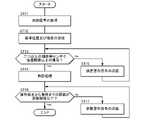
相対距離が第2閾値を超えたと行動計画部43が判定した時(ST32のYes)に、制御装置15は操作端末3に警告起動信号を送信し、警告起動信号を受信した操作端末3の処理部35が、相対距離が第1閾値に近づいている旨を出入力部32に画像や文字の表示及び/又は音声や警告音等により出力する(ST33)。 When theaction planning unit 43 determines that the relative distance exceeds the second threshold value (Yes of ST32), thecontrol device 15 transmits a warning activation signal to theoperation terminal 3, and the processing of theoperation terminal 3 that receives the warning activation signal. Theunit 35 outputs to the input /output unit 32 that the relative distance is approaching the first threshold value by displaying an image or a character and / or by a voice or a warning sound (ST33).

更に、相対距離が第1閾値を超えたと行動計画部43が判定すると(ST34のYes)、制御装置15の走行制御部44は車両を停止させる(ST35)。更に、制御装置15は操作端末3に信号を送信し、信号を受信した操作端末3の処理部35は、相対距離が第1閾値を超えたため車両を停止させた旨を出入力部32に文字や画像の表示及び/又は音声等により出力する(ST36)。なお、出入力部32は、車両の移動を再開するためにユーザが位置するべき推奨位置を画像等により出力することが好ましい。 Further, when theaction planning unit 43 determines that the relative distance exceeds the first threshold value (Yes of ST34), thetravel control unit 44 of thecontrol device 15 stops the vehicle (ST35). Further, thecontrol device 15 transmits a signal to theoperation terminal 3, and theprocessing unit 35 of theoperation terminal 3 that has received the signal informs the input /output unit 32 that the vehicle has been stopped because the relative distance exceeds the first threshold value. And / or output by voice or the like (ST36). It is preferable that the input /output unit 32 outputs a recommended position where the user should be located in order to resume the movement of the vehicle by an image or the like.

相対距離が第1閾値を超えた状態が継続している場合であって(ST37のNo)、ユーザによる遠隔駐車処理を行うための操作端末3に対する所定の操作が継続され(ST38のYes)、車両が停止してから所定の時間が経過した(ST39のYes)時は、車両の報知装置14で警告を発する(ST40)。例えば、警告は、前照灯30若しくはハザードランプ61の点滅、ホーン31による警告音、及び/又は、スピーカ62による警告音若しくは相対距離が第1閾値を超えた旨のメッセージである。ユーザによる操作端末3に対する所定の操作がない場合(ST38のNo)や、車両が停止してから所定の時間が経過するまで(ST39のNo)は、車両の報知装置14による警告は実施されない。 When the relative distance exceeds the first threshold value continues (No in ST37), the predetermined operation for theoperation terminal 3 for performing the remote parking process by the user is continued (Yes in ST38). When a predetermined time has elapsed since the vehicle stopped (Yes in ST39), thevehicle notification device 14 issues a warning (ST40). For example, the warning is a blinking of theheadlight 30 or thehazard lamp 61, a warning sound by thehorn 31, and / or a warning sound by thespeaker 62 or a message indicating that the relative distance has exceeded the first threshold value. When there is no predetermined operation on theoperation terminal 3 by the user (No of ST38) or until a predetermined time elapses after the vehicle is stopped (No of ST39), the warning by thevehicle notification device 14 is not executed.

ユーザが車両に近づいて相対距離が第1閾値以下となり(ST37のYes)、操作端末3の出入力部32に所定の操作が行われると(ST41のYes)、走行制御部44は、走行経路に沿った車両の移動を再開する(ST42)。 When the user approaches the vehicle and the relative distance becomes equal to or less than the first threshold value (Yes in ST37) and a predetermined operation is performed on the input /output unit 32 of the operation terminal 3 (Yes in ST41), thetravel control unit 44 moves to the travel route. The movement of the vehicle along the line is resumed (ST42).

車両の移動の再開後、又は相対距離が第1又は第2閾値を超えずに(ST32のNo、ST34のNo)車両の移動が継続している時に、車両が停止位置に到達したと制御装置15が判定すると(ST43のYes)、走行制御部44は車両を停止させる(ST44、図8の駐車処理)。車両が停止位置に到達するまでは(ST43のNo)ST32からの処理が繰り返される。 After resuming the movement of the vehicle, or when the relative distance does not exceed the first or second threshold value (No of ST32, No of ST34) and the movement of the vehicle continues, the control device determines that the vehicle has reached the stop position. When 15 determines (Yes in ST43), thetravel control unit 44 stops the vehicle (ST44, parking process in FIG. 8). The process from ST32 (No of ST43) is repeated until the vehicle reaches the stop position.

端末と車両との相対距離が第1閾値を超えた時に車両を停止させることにより、ユーザが車両から所定の範囲内にいる場合にのみ車両の移動が可能となる。車両の移動中は、特に車両を注視する必要はないため、ユーザによる車両の周辺の監視が妨げられない。そして、相対距離が第1閾値を超えたため車両が停止した旨が操作端末3の出入力部32に出力されることにより、ユーザは、車両の停止の原因が相対距離が第1閾値を超えたことであること、及び車両の移動を再開するためには車両に近づく必要があることを認識できる。 By stopping the vehicle when the relative distance between the terminal and the vehicle exceeds the first threshold value, the vehicle can be moved only when the user is within a predetermined range from the vehicle. Since it is not necessary to pay particular attention to the vehicle while the vehicle is moving, the user's monitoring of the surroundings of the vehicle is not hindered. Then, the fact that the vehicle has stopped because the relative distance exceeds the first threshold value is output to the input /output unit 32 of theoperation terminal 3, so that the user can see that the cause of the vehicle stop is that the relative distance exceeds the first threshold value. It can be recognized that this is the case and that it is necessary to approach the vehicle in order to resume the movement of the vehicle.

ところで、車両の遠隔操作中、ユーザは操作端末3ではなく車両又はその周辺を監視している。そのため、相対距離が第1閾値を超えたため車両が停止した旨を操作端末3の出入力部32に表示させても、ユーザがそれに気付かずに操作端末3の操作を継続する可能性がある。出入力部32が音声により相対距離が第1閾値を超えたため車両が停止した旨を報知しても、周囲の騒音によってユーザがその音声を聞き取れない場合もあり得る。そこで、車両の側から警報を発することにより、車両又はその周辺を監視しているユーザに注意を喚起して、操作端末3から出力された内容を確認することを促すことができる。 By the way, during remote control of the vehicle, the user monitors the vehicle or its surroundings instead of theoperation terminal 3. Therefore, even if the input /output unit 32 of theoperation terminal 3 displays that the vehicle has stopped because the relative distance exceeds the first threshold value, the user may continue to operate theoperation terminal 3 without noticing it. Even if the input /output unit 32 notifies by voice that the vehicle has stopped because the relative distance exceeds the first threshold value, the user may not be able to hear the voice due to ambient noise. Therefore, by issuing an alarm from the vehicle side, it is possible to call attention to the user who is monitoring the vehicle or its surroundings and urge the user to confirm the content output from theoperation terminal 3.

ここで、ユーザが操作端末3に対する所定の操作を継続している場合は、ユーザは相対距離が第1閾値を超えたことに気付いていないと推定される。この場合にのみ車両の側から警報を発することにより、周囲にとって迷惑行為となり得る車両の側からの警報を抑制することができる。 Here, when the user continues a predetermined operation on theoperation terminal 3, it is presumed that the user is unaware that the relative distance has exceeded the first threshold value. By issuing an alarm from the vehicle side only in this case, it is possible to suppress the alarm from the vehicle side, which may be a nuisance to the surroundings.

また、車両の側から警報を発しなくても、ユーザが操作端末3を確認する可能性はある。そこで、車両が停止してから所定の時間が経過するまでは車両の側からの警報を発しないことにより、ユーザが自主的に操作端末3を確認することを期待して、周囲にとって迷惑行為となり得る車両の側からの警報を抑制することができる。 Further, there is a possibility that the user confirms theoperation terminal 3 without issuing an alarm from the vehicle side. Therefore, by not issuing an alarm from the vehicle side until a predetermined time has elapsed after the vehicle has stopped, it is annoying to the surroundings in the expectation that the user will voluntarily check theoperation terminal 3. It is possible to suppress the alarm from the side of the vehicle to obtain.

また、車両の停止後、車両の移動を再開するためにユーザが位置するべき推奨位置が出入力部32に出力されることにより、ユーザに推奨位置に移動することを促し、車両の移動を速やかに再開させることができる。 Further, after the vehicle is stopped, the recommended position where the user should be located in order to resume the movement of the vehicle is output to the input /output unit 32, thereby urging the user to move to the recommended position and promptly moving the vehicle. Can be restarted.

また、ユーザに車両から第1閾値以下の距離の範囲内にいる間に操作端末3が警告を発することにより、ユーザに車両から第1閾値以下の距離の範囲内にいることを促すことができる。ユーザが車両から第1閾値以下の距離の範囲内にいることにより、車両が停止せずに遠隔駐車処理が続行され、遠隔駐車処理に要する時間が延びることを抑制することがされる。 Further, by issuing a warning to the user while theoperation terminal 3 is within the range of the distance below the first threshold value from the vehicle, it is possible to urge the user to be within the range of the distance below the first threshold value from the vehicle. .. When the user is within the range of the distance equal to or less than the first threshold value, the remote parking process is continued without the vehicle stopping, and it is possible to suppress the extension of the time required for the remote parking process.

以上で具体的実施形態の説明を終えるが、本発明は上記実施形態に限定されることなく幅広く変形実施することができる。例えば、制御装置が操作端末に設けられてもよい。また、駐車処理だけではなく、駐車位置から所定の位置まで車両を出庫させる等の遠隔自動移動処理に本発明を適用してもよい。操作端末と車両との相対距離を算出するための位置判定部は、測距用ユニットに代えて、操作端末側に設けられた測距用の手段であってもよく、また、操作端末の位置検出部及び車両の自車位置特定部であってもよい。 Although the description of the specific embodiment is completed above, the present invention can be widely modified without being limited to the above embodiment. For example, the control device may be provided in the operation terminal. Further, the present invention may be applied not only to parking processing but also to remote automatic movement processing such as leaving a vehicle from a parking position to a predetermined position. The position determination unit for calculating the relative distance between the operation terminal and the vehicle may be a means for distance measurement provided on the operation terminal side instead of the distance measurement unit, and the position of the operation terminal. It may be a detection unit and a vehicle position specifying unit of the vehicle.

1 :遠隔駐車システム(車両制御システム)
3 :操作端末
7 :外界センサ
14 :報知装置
15 :制御装置
21 :測距用ユニット(位置判定部)
32 :出入力部
33 :位置検出部(位置判定部)
42 :自車位置特定部(位置判定部)
1: Remote parking system (vehicle control system)
3: Operation terminal 7: External sensor 14: Notification device 15: Control device 21: Distance measuring unit (position determination unit)
32: Input / output unit 33: Position detection unit (position determination unit)
42: Own vehicle position identification unit (position determination unit)

Claims (5)

Translated fromJapanese
車両側に設けられ、外界センサからの出力に基づき、初期位置から停止位置に向かって車両を移動させて前記停止位置に停止させる遠隔自動移動処理を実行可能な制御装置と、
ユーザの入力に基づき、前記遠隔自動移動処理の進行を制御する信号を前記制御装置に送信可能な、前記ユーザにより携帯可能な操作端末とを有する車両制御システムであって、
前記車両及び/又は前記操作端末に設けられた、前記操作端末と前記車両との間の距離を計測する位置判定部を有し、
前記制御装置が、前記位置判定部からの信号に基づき、前記距離が第1閾値を超えたと判定したときに、前記車両を停止させ、前記操作端末に前記距離が前記第1閾値を超えた旨を出力するべき信号を送信し、
前記制御装置が、前記位置判定部からの信号に基づき前記距離が前記第1閾値を超えたことを判定したときに、前記車両を停止させると共に、前記車両の側から警報を発し、
前記制御装置は、前記ユーザが所定の入力操作を継続的に実行しているときにのみ、前記遠隔自動移動処理における前記車両の走行を実施するように構成され、前記距離が前記第1閾値を超え、かつ前記ユーザが前記所定の入力操作を継続しているときにのみ、前記車両の側から前記警報を発することを特徴とする車両制御システム。
A control device provided on the vehicle side that can execute remote automatic movement processing that moves the vehicle from the initial position toward the stop position and stops it at the stop position based on the output from the external sensor.
A vehicle control system having an operation terminal portable to the user, capable of transmitting a signal for controlling the progress of the remote automatic movement process to the control device based on a user's input.
It has a position determination unit provided on the vehicle and / or the operation terminal to measure the distance between the operation terminal and the vehicle.
When the control device determines that the distance exceeds the first threshold value based on the signal from the position determination unit, the vehicle is stopped and the operation terminal is informed that the distance exceeds the first threshold value. Senda signal to output,
When the control device determines that the distance exceeds the first threshold value based on the signal from the position determination unit, the vehicle is stopped and an alarm is issued from the side of the vehicle.
The control device is configured to carry out the travel of the vehicle in the remote automatic movement process only when the user continuously executes a predetermined input operation, and the distance sets the first threshold value. A vehicle control system characterized in that thealarm is issued from the side of the vehicle only when the value is exceeded and the user continues the predetermined input operation .
前記制御装置は、前記遠隔自動移動処理の実行中に前記距離が前記第1閾値を超えたことにより前記車両を停止してから所定の時間内には、前記車両の側からの前記警報を発しないことを特徴とする請求項に記載の車両制御システム。The control device issues the alarm from the side of the vehicle within a predetermined time after the vehicle is stopped due to the distance exceeding the first threshold value during the execution of the remote automatic movement process. The vehicle control system according to claim1 , wherein the vehicle control system is not provided.車両側に設けられ、外界センサからの出力に基づき、初期位置から停止位置に向かって車両を移動させて前記停止位置に停止させる遠隔自動移動処理を実行可能な制御装置と、A control device provided on the vehicle side that can execute remote automatic movement processing that moves the vehicle from the initial position toward the stop position and stops it at the stop position based on the output from the external sensor.
ユーザの入力に基づき、前記遠隔自動移動処理の進行を制御する信号を前記制御装置に送信可能な、前記ユーザにより携帯可能な操作端末とを有する車両制御システムであって、A vehicle control system having an operation terminal portable to the user, capable of transmitting a signal for controlling the progress of the remote automatic movement process to the control device based on a user's input.
前記車両及び/又は前記操作端末に設けられた、前記操作端末と前記車両との間の距離を計測する位置判定部を有し、It has a position determination unit provided on the vehicle and / or the operation terminal to measure the distance between the operation terminal and the vehicle.
前記制御装置が、前記位置判定部からの信号に基づき、前記距離が第1閾値を超えたと判定したときに、前記車両を停止させ、前記操作端末に前記距離が前記第1閾値を超えた旨を出力するべき信号を送信し、When the control device determines that the distance exceeds the first threshold value based on the signal from the position determination unit, the vehicle is stopped and the operation terminal is informed that the distance exceeds the first threshold value. Send a signal to output,
前記制御装置が、前記位置判定部からの信号に基づき前記距離が前記第1閾値を超えたことを判定したときに、前記車両を停止させると共に、前記車両の側から警報を発し、When the control device determines that the distance exceeds the first threshold value based on the signal from the position determination unit, the vehicle is stopped and an alarm is issued from the side of the vehicle.
前記制御装置は、前記遠隔自動移動処理の実行中に前記距離が前記第1閾値を超えたことにより前記車両を停止してから所定の時間内には、前記車両の側からの前記警報を発しないことを特徴とする車両制御システム。The control device issues the alarm from the side of the vehicle within a predetermined time after the vehicle is stopped due to the distance exceeding the first threshold value during the execution of the remote automatic movement process. A vehicle control system characterized by not doing so.
前記制御装置は、前記遠隔自動移動処理の実行中に前記距離が前記第1閾値を超えたことにより前記車両を停止させた時、前記遠隔自動移動処理に基づく前記車両の移動を再開するために前記ユーザが位置するべき推奨位置を前記操作端末に出力させることを特徴とする請求項1~の何れか一項に記載の車両制御システム。The control device is for restarting the movement of the vehicle based on the remote automatic movement process when the vehicle is stopped due to the distance exceeding the first threshold value during the execution of the remote automatic movement process. The vehicle control system according to any one of claims 1 to3 , wherein the operation terminal outputs a recommended position to which the user should be located. 前記制御装置は、前記位置判定部からの信号に基づき、前記距離が前記第1閾値よりも小さい第2閾値を超えたと判定したときに、前記操作端末に警告を発するべき警告起動信号を送信することを特徴とする請求項1~の何れか一項に記載の車両制御システム。Based on the signal from the position determination unit, the control device transmits a warning activation signal to issue a warning to the operation terminal when it is determined that the distance exceeds a second threshold value smaller than the first threshold value. The vehicle control system according to any one of claims 1 to4 , wherein the vehicle control system is characterized by the above.
JP2019173201A2019-09-242019-09-24 Vehicle control systemActiveJP7094255B2 (en)

Priority Applications (3)

Application NumberPriority DateFiling DateTitle
JP2019173201AJP7094255B2 (en)2019-09-242019-09-24 Vehicle control system
US17/028,141US11480957B2 (en)2019-09-242020-09-22Vehicle control system
CN202011007226.6ACN112622877B (en)2019-09-242020-09-23vehicle control system

Applications Claiming Priority (1)

Application NumberPriority DateFiling DateTitle
JP2019173201AJP7094255B2 (en)2019-09-242019-09-24 Vehicle control system

Publications (2)

Publication NumberPublication Date
JP2021049838A JP2021049838A (en)2021-04-01
JP7094255B2true JP7094255B2 (en)2022-07-01

Family

ID=74881925

Family Applications (1)

Application NumberTitlePriority DateFiling Date
JP2019173201AActiveJP7094255B2 (en)2019-09-242019-09-24 Vehicle control system

Country Status (3)

CountryLink
US (1)US11480957B2 (en)
JP (1)JP7094255B2 (en)
CN (1)CN112622877B (en)

Families Citing this family (8)

* Cited by examiner, † Cited by third party
Publication numberPriority datePublication dateAssigneeTitle
GB2612105B (en)*2021-10-222024-08-28Jaguar Land Rover LtdControl system for a vehicle
WO2023120682A1 (en)*2021-12-232023-06-29株式会社J-QuAD DYNAMICSAutomatic unloading system and automatic unloading method
JP7444915B2 (en)*2022-03-222024-03-06本田技研工業株式会社 Information terminal, control method, and control program
CN116968754A (en)*2022-04-242023-10-31中兴通讯股份有限公司Automatic driving method, controller and system
CN115179882A (en)*2022-07-142022-10-14深圳市鼎元智能科技有限公司 Vehicle-mounted 5G intelligent terminal system and its working method
FR3147015A1 (en)*2023-03-202024-09-27Psa Automobiles Sa Method and control device for manually controlling a vehicle remotely.
US20250138528A1 (en)*2023-11-012025-05-01Ford Global Technologies, LlcSystems and methods for enabling vehicle movement via an external interface
CN120552894A (en)*2025-07-292025-08-29质子汽车科技有限公司 Special vehicle control system and method

Citations (7)

* Cited by examiner, † Cited by third party
Publication numberPriority datePublication dateAssigneeTitle
JP2007295033A (en)2006-04-202007-11-08Toyota Motor Corp Remote operation control device and operation terminal thereof
JP2016097927A (en)2014-11-262016-05-30株式会社デンソー Vehicle remote control system, in-vehicle device
JP2017007399A (en)2015-06-172017-01-12日産自動車株式会社Parking support device and method
JP2018086920A (en)2016-11-292018-06-07トヨタ自動車株式会社Parking support device
JP2018176823A (en)2017-04-042018-11-15株式会社デンソー Vehicle portable device
JP2019057767A (en)2017-09-202019-04-11株式会社デンソーPortable terminal, remote operation method
US20190220001A1 (en)2018-01-122019-07-18Ford Global Technologies, LlcMobile device tethering for remote parking assist

Family Cites Families (5)

* Cited by examiner, † Cited by third party
Publication numberPriority datePublication dateAssigneeTitle
KR101459835B1 (en)*2012-10-112014-11-07현대자동차주식회사Apparatus and method for display control of object
JP2015089733A (en)2013-11-062015-05-11トヨタ自動車株式会社 Parking assistance system
US10336318B2 (en)*2015-06-222019-07-02Ford Global Technologies, LlcSystems and methods for vehicle park assist
JP6569461B2 (en)2015-10-192019-09-04トヨタ自動車株式会社 Parking assistance device
US10210760B2 (en)*2016-09-212019-02-19Dura Operating, LlcSystem and method for autonomous parking of a vehicle

Patent Citations (7)

* Cited by examiner, † Cited by third party
Publication numberPriority datePublication dateAssigneeTitle
JP2007295033A (en)2006-04-202007-11-08Toyota Motor Corp Remote operation control device and operation terminal thereof
JP2016097927A (en)2014-11-262016-05-30株式会社デンソー Vehicle remote control system, in-vehicle device
JP2017007399A (en)2015-06-172017-01-12日産自動車株式会社Parking support device and method
JP2018086920A (en)2016-11-292018-06-07トヨタ自動車株式会社Parking support device
JP2018176823A (en)2017-04-042018-11-15株式会社デンソー Vehicle portable device
JP2019057767A (en)2017-09-202019-04-11株式会社デンソーPortable terminal, remote operation method
US20190220001A1 (en)2018-01-122019-07-18Ford Global Technologies, LlcMobile device tethering for remote parking assist

Also Published As

Publication numberPublication date
US20210089021A1 (en)2021-03-25
JP2021049838A (en)2021-04-01
US11480957B2 (en)2022-10-25
CN112622877A (en)2021-04-09
CN112622877B (en)2023-09-29

Similar Documents

PublicationPublication DateTitle
JP7094255B2 (en) Vehicle control system
JP7097866B2 (en) Remote parking system
JP7094256B2 (en) Remote parking system
JP7097867B2 (en) Remote parking system
JP6310565B2 (en) Driving assistance device
US9796416B2 (en)Automated driving apparatus and automated driving system
JP6852638B2 (en) Self-driving vehicle dispatch system, self-driving vehicle, and vehicle dispatch method
CN109923018B (en)Vehicle control system, vehicle control method, and storage medium
US9896098B2 (en)Vehicle travel control device
US11256247B2 (en)Vehicle control system
CN108082191A (en)Vehicle control system, control method for vehicle and the medium for storing vehicle control program
US11586224B2 (en)Vehicle control apparatus, vehicle, operation method for vehicle control apparatus, and storage medium
WO2017187759A1 (en)Assistance system, portable terminal, and on-board device
JP2021094932A (en)Parking support system
JP2023030111A (en) Driving support device, driving support method, and program
US11104342B2 (en)Vehicle control device, vehicle, and vehicle control method
US20200189589A1 (en)Vehicle control device and vehicle control method
US12429343B2 (en)Vehicle control device and vehicle control system

Legal Events

DateCodeTitleDescription
A621Written request for application examination

Free format text:JAPANESE INTERMEDIATE CODE: A621

Effective date:20210329

A131Notification of reasons for refusal

Free format text:JAPANESE INTERMEDIATE CODE: A131

Effective date:20220419

A521Request for written amendment filed

Free format text:JAPANESE INTERMEDIATE CODE: A523

Effective date:20220531

TRDDDecision of grant or rejection written
A01Written decision to grant a patent or to grant a registration (utility model)

Free format text:JAPANESE INTERMEDIATE CODE: A01

Effective date:20220614

A61First payment of annual fees (during grant procedure)

Free format text:JAPANESE INTERMEDIATE CODE: A61

Effective date:20220621

R150Certificate of patent or registration of utility model

Ref document number:7094255

Country of ref document:JP

Free format text:JAPANESE INTERMEDIATE CODE: R150


[8]ページ先頭

©2009-2025 Movatter.jp