JP7093911B2 - Inner tube - Google Patents
Inner tubeDownload PDFInfo
- Publication number
- JP7093911B2 JP7093911B2JP2018107080AJP2018107080AJP7093911B2JP 7093911 B2JP7093911 B2JP 7093911B2JP 2018107080 AJP2018107080 AJP 2018107080AJP 2018107080 AJP2018107080 AJP 2018107080AJP 7093911 B2JP7093911 B2JP 7093911B2
- Authority
- JP
- Japan
- Prior art keywords
- inner tube
- sliding member
- tip
- sliding
- end side
- Prior art date
- Legal status (The legal status is an assumption and is not a legal conclusion. Google has not performed a legal analysis and makes no representation as to the accuracy of the status listed.)
- Active
Links
Images


Landscapes
- Endoscopes (AREA)
- Instruments For Viewing The Inside Of Hollow Bodies (AREA)
Description
Translated fromJapanese本発明は、内視鏡と鉗子やメス等の処置具とを体腔内へ挿入する際に、その挿入を補助する処置具挿入補助具のインナーチューブに関する。 The present invention relates to an inner tube of a treatment tool insertion assisting tool that assists the insertion of an endoscope and a treatment tool such as forceps or a scalpel into a body cavity.
従来から、内視鏡と該内視鏡の観察下において使用される鉗子やメス等の処置具とを体腔内へ挿入して治療を行う手技が行われている。 Conventionally, a procedure has been performed in which an endoscope and a treatment tool such as forceps or a scalpel used under the observation of the endoscope are inserted into a body cavity for treatment.
この種の手技を行うために、前記内視鏡と前記処置具とを夫々内部に進退自在に挿通可能である複数のインナーチューブと、前記インナーチューブを挿通可能であるアウターチューブとを備える処置具挿入補助具が知られている。 In order to perform this kind of procedure, a treatment tool including a plurality of inner tubes into which the endoscope and the treatment tool can be freely inserted and retreated, and an outer tube through which the inner tube can be inserted. Insertion aids are known.
この処置具挿入補助具の使用方法は、まず、前記アウターチューブの先端を被処置部に対向させる。次いで、該先端から前記インナーチューブの先端を突出させる。それから、前記先端にワイヤーを介して固定されると共に、前記インナーチューブに摺動可能に取り付けられた摺動部材を基端側に牽引することで、前記インナーチューブの先端を前記アウターチューブの軸線から離れる方向に向けて放射状に屈曲させる。このとき、前記摺動部材の裏面側に取り付けられた小さい楔状のスライドストッパーを、摺動部材とインナーチューブとの間に差し込むことで、該屈曲状態は保持される。 To use this treatment tool insertion assisting tool, first, the tip of the outer tube is made to face the treated portion. Next, the tip of the inner tube is projected from the tip. Then, the tip of the inner tube is pulled from the axis of the outer tube by pulling the sliding member slidably attached to the inner tube toward the proximal end while being fixed to the tip via a wire. Bend radially toward the distance. At this time, the bent state is maintained by inserting a small wedge-shaped slide stopper attached to the back surface side of the sliding member between the sliding member and the inner tube.
さらに、内視鏡及び処置具を夫々前進させてインナーチューブから突出させた後、該内視鏡及び該処置具を前記アウターチューブの軸線に近づく方向に屈曲させて被処置部に対向させる。 Further, after the endoscope and the treatment tool are advanced and projected from the inner tube, the endoscope and the treatment tool are bent in a direction approaching the axis of the outer tube to face the treated portion.
以上により、前記処置具挿入補助具は、十分な作業空間と視野を確保でき、距離感が掴み易くすることができる。 As described above, the treatment tool insertion assisting tool can secure a sufficient working space and a field of view, and can easily grasp a sense of distance.
ところで、前記インナーチューブを屈曲状態で保持するためには、小さいスライドストッパーを操作しなければならないため、操作が容易ではないという問題がある。また、屈曲状態を解除するためには、差し込まれたスライドストッパーを摺動部材とインナーチューブとの間から、爪を引っ掛けて抜く操作を要するため、同様に操作が容易ではないという問題がある。 By the way, in order to hold the inner tube in a bent state, a small slide stopper must be operated, which causes a problem that the operation is not easy. Further, in order to release the bent state, it is necessary to hook and pull out the inserted slide stopper from between the sliding member and the inner tube, so that there is a problem that the operation is not easy as well.
前記問題を解決するために、前記摺動部材に前記ワイヤー部材の他端を固定するとともに、該摺動部材に前記インナーチューブの軸線方向に交差する方向を回転軸として回動可能な掛止部材を設けることが考えられる。前記掛止部材によれば、前記摺動部材を前記インナーチューブの基端側に摺動させたときに、該掛止部材を回動させて、前記インナーチューブに掛止することにより、前記屈曲部を屈曲させた状態で保持することができ、高い操作性を得ることができる。 In order to solve the problem, the other end of the wire member is fixed to the sliding member, and the hooking member is rotatable about the direction intersecting the axial direction of the inner tube with the sliding member as a rotation axis. It is conceivable to provide. According to the hooking member, when the sliding member is slid toward the base end side of the inner tube, the hooking member is rotated and hooked on the inner tube to bend the inner tube. The portion can be held in a bent state, and high operability can be obtained.
しかしながら、前記掛止部材によれば、前記屈曲部の屈曲角度を任意に調整することができず、さらに改良が望まれる。前記掛止部材を掛止する掛止部として、前記インナーチューブの基端側に階段状の突起部を設けることも考えられるが、このようにしても前記屈曲部の屈曲角度を段階的に調整することができるに過ぎない。 However, according to the hooking member, the bending angle of the bent portion cannot be adjusted arbitrarily, and further improvement is desired. It is conceivable to provide a stepped protrusion on the base end side of the inner tube as a hooking portion for hooking the hooking member, but even in this case, the bending angle of the bent portion is adjusted stepwise. You can only do it.
上記の点に鑑み、本発明は、操作性が高く、屈曲部の屈曲角度を任意に調整できるインナーチューブを提供することを目的とする。 In view of the above points, it is an object of the present invention to provide an inner tube having high operability and capable of arbitrarily adjusting the bending angle of the bent portion.
かかる目的を達成するために、本発明のインナーチューブは、内視鏡及び処置具の体腔内への導入を補助する処置具挿入補助具に挿入されるとともに、該内視鏡及び処置具を内部に挿通可能なインナーチューブであって、該インナーチューブの先端に設けられ、可撓性を有する屈曲可能な屈曲部と、前記屈曲部の先端に一端が固定された第1のワイヤー部材と、前記第1のワイヤー部材の他端が固定され、前記インナーチューブの外周を該インナーチューブの軸線方向に沿って摺動可能に取り付けられた第1の摺動部材と、前記第1の摺動部材に調節ねじにより螺着され、前記調節ねじを操作することにより前記インナーチューブの外周を該インナーチューブの軸線方向に沿って摺動可能に取り付けられた第2の摺動部材と、前記第1の摺動部材を前記インナーチューブの基端側に摺動させて前記屈曲部を屈曲させた状態で保持する保持機構とを備え、該保持機構は、前記第2の摺動部材に設けられ、前記軸線方向に交差する方向を回転軸として、回動可能な掛止部材と、前記インナーチューブの基端に設けられ、基端側に向かって回動された前記掛止部材が掛止される突起部とを有することを特徴とする。 In order to achieve such an object, the inner tube of the present invention is inserted into a treatment tool insertion assisting tool that assists the introduction of the endoscope and the treatment tool into the body cavity, and the endoscope and the treatment tool are internally inserted. An inner tube that can be inserted into the inner tube, which is provided at the tip of the inner tube and has a flexible bendable portion, and a first wire member having one end fixed to the tip of the bend portion. The other end of the first wire member is fixed, and the outer periphery of the inner tube is slidably attached along the axial direction of the inner tube to the first sliding member and the first sliding member. A second sliding member screwed by an adjusting screw and slidably attached to the outer periphery of the inner tube along the axial direction of the inner tube by operating the adjusting screw, and the first sliding member. A holding mechanism for holding the bent portion in a bent state by sliding the moving member toward the base end side of the inner tube is provided, and the holding mechanism is provided on the second sliding member and the axis line. A rotatable hooking member with a direction intersecting the directions as a rotation axis, and a protrusion provided at the base end of the inner tube and to which the hooking member rotated toward the base end side is hooked. It is characterized by having and.
本発明のインナーチューブは、屈曲部と第1の摺動部材とが第1のワイヤー部材を介して連結されているため、処置具挿入補助具の先端からインナーチューブを突出させた状態で、第1の摺動部材を基端側に牽引することで、屈曲部が屈曲される。このとき、第2の摺動部材は調節ねじにより前記第1の摺動部材に螺着されている。そこで、前記状態から、第2の摺動部材に設けられた掛止部材をインナーチューブの基端側に向かって回動させて突起部に掛止させることで、屈曲部が屈曲した状態を保持させる。 In the inner tube of the present invention, since the bent portion and the first sliding member are connected via the first wire member, the inner tube is in a state of protruding from the tip of the treatment tool insertion assisting tool. By pulling the sliding member of No. 1 toward the proximal end side, the bent portion is bent. At this time, the second sliding member is screwed to the first sliding member by the adjusting screw. Therefore, from the above state, the hooking member provided on the second sliding member is rotated toward the base end side of the inner tube and hooked on the protrusion to maintain the bent state. Let me.
従って、本発明のインナーチューブは、掛止部材を回転させて突起部に引っ掛ける・外すという操作によって屈曲状態の保持及び解除ができるため、高い操作性を得ることができる。 Therefore, the inner tube of the present invention can be held and released in the bent state by the operation of rotating the hooking member and hooking / removing it on the protrusion, so that high operability can be obtained.
また、掛止部材が突起部に掛止されて第2の摺動部材が固定されているときに、第1の摺動部材は調節ねじを操作することにより、第2の摺動部材に対して相対的に進退することができる。すなわち、第1の摺動部材は調節ねじを締めることにより第2の摺動部材に近接し、調節ねじを緩めることにより第2の摺動部材から離間する。この結果、本発明のインナーチューブは、第1の摺動部材により屈曲部に対して第1のワイヤー部材を進退させることができ、屈曲部の屈曲角度を任意に調整することができる。 Further, when the hooking member is hooked on the protrusion and the second sliding member is fixed, the first sliding member operates the adjusting screw to the second sliding member. You can move forward and backward relatively. That is, the first sliding member approaches the second sliding member by tightening the adjusting screw, and separates from the second sliding member by loosening the adjusting screw. As a result, in the inner tube of the present invention, the first wire member can be advanced and retracted with respect to the bent portion by the first sliding member, and the bending angle of the bent portion can be arbitrarily adjusted.
本発明のインナーチューブは、前記インナーチューブの軸線に対し前記第1のワイヤー部材と対称となる側で、前記屈曲部の先端に一端が固定された第2のワイヤー部材と、前記第2のワイヤー部材の他端が固定され、前記インナーチューブの外周を該インナーチューブの軸線方向に沿って摺動可能に取り付けられた第3の摺動部材と、前記第3の摺動部材を前記インナーチューブの基端側に付勢する弾性部材とを有することが好ましい。 The inner tube of the present invention has a second wire member having one end fixed to the tip of the bent portion on the side symmetrical to the first wire member with respect to the axis of the inner tube, and the second wire. A third sliding member to which the other end of the member is fixed and slidably attached to the outer periphery of the inner tube along the axial direction of the inner tube, and the third sliding member of the inner tube. It is preferable to have an elastic member that urges the base end side.
本発明のインナーチューブは、前記弾性部材を備えることにより、第1の摺動部材が第2の摺動部材から離間して、屈曲部の屈曲角度が小さくなるときに、第3の摺動部材をインナーチューブの基端側に付勢することができる。この結果、第3の摺動部材により第2のワイヤー部材が牽引されることとなり、屈曲部の屈曲角度を小さくする動作を円滑に行うことができる。 By providing the elastic member, the inner tube of the present invention has a third sliding member when the first sliding member is separated from the second sliding member and the bending angle of the bent portion becomes smaller. Can be urged to the base end side of the inner tube. As a result, the second wire member is towed by the third sliding member, and the operation of reducing the bending angle of the bent portion can be smoothly performed.
本発明のインナーチューブにおいて、前記突起部は、前記屈曲部を屈曲させるまで前記第1の摺動部材が摺動されたときに、前記第2の摺動部材が接する位置に設けられていることが好ましい。 In the inner tube of the present invention, the protrusion is provided at a position where the second sliding member comes into contact with the first sliding member when the first sliding member is slid until the bent portion is bent. Is preferable.
これによれば、第2の摺動部材が突起部に接するまで第1の摺動部材を基端側に牽引するだけで、屈曲部が適度に屈曲するので、操作性が高い。 According to this, only by pulling the first sliding member toward the proximal end side until the second sliding member comes into contact with the protrusion, the bent portion is appropriately bent, so that the operability is high.
本発明のインナーチューブにおいて、前記第2の摺動部材の回転軸から前記突起部までの距離より前記掛止部の長さは小であり、前記掛止部は伸縮可能な弾性材からなることを特徴とする。 In the inner tube of the present invention, the length of the hooking portion is smaller than the distance from the rotation axis of the second sliding member to the protrusion, and the hooking portion is made of a stretchable elastic material. It is characterized by.
これによれば、掛止部を引っ張って伸ばしながら突起部に引っ掛けるという操作で、屈曲状態が緩むことを防止することができる。 According to this, it is possible to prevent the bent state from loosening by the operation of pulling and extending the hooking portion and hooking it on the protrusion.
本発明の実施の形態に係る処置具挿入補助具10について説明する。処置具挿入補助具10は、内視鏡並びに鉗子、メス等の処置具(図示せず)の体内への導入を補助するために用いられる。 The treatment tool
処置具挿入補助具10は、図1に示すように、主として、インナーチューブ20、アウターチューブ30から構成される。アウターチューブ30の内部に1本又は複数本のインナーチューブ20が挿入される。 As shown in FIG. 1, the treatment tool
アウターチューブ30は、可撓性を有する屈曲可能な筒状体であり、内壁面に先端側から基端側にかけて軸方向に延設された複数の案内部(図示せず)を備えている。案内部は、例えば、アウターチューブ30の内壁面に形成された蟻溝であり、内壁面に円周方向に等間隔に形成されている。 The
アウターチューブ30の基端側には、ガイドパイプ32、空気漏れ防止リング33と、バルブシート(図示せず)が取り付けられている。 A
ガイドパイプ32は、アウターチューブ30と空気漏れ防止リング33とを接続する部材であり、ステンレス等の金属や樹脂などの硬質材から形成されている。空気漏れ防止リング33はバルブシートと接着されている。空気漏れ防止リング33は、ガイドパイプ32に対して着脱可能に取り付けられている。バルブシートには、インナーチューブ20が挿通される複数の孔が形成されている。 The
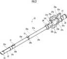
図2及び図3に示すように、インナーチューブ20は、可撓性を有する筒状体であり、内視鏡並びに鉗子やメス等の処置具を内部に挿通可能となっている。インナーチューブ20は外周面に親水性加工が施されている。 As shown in FIGS. 2 and 3, the
インナーチューブ20は、本実施形態では、外径が同じものが4本取り付けられているが、外径が異なるものを取り付けてもよい。 In the present embodiment, four
インナーチューブ20は、ポリプロピレン、塩化ビニル等の軟性プラスチック、ゴム等の軟質材からなる軟質部20aと、軟質部20aより硬質であってABS、ポリカーボネートなどの硬性プラスチックや硬質ゴムなどの硬質材からなる硬質部20bとが軸方向に交互に結合されて構成されている。 The
インナーチューブ20は、外周面の先端から基端に亘って、アウターチューブ30の案内部に係合して摺動可能とする係合部21と、挿入深さを把握するための目盛(図示せず)とを備えている。 The
インナーチューブ20の係合部21は、本実施形態では、インナーチューブ20の外周面に突出する蟻ほぞ状の突起であるが、アウターチューブ30の案内部に対して係合可能であれば任意の形状とすることができる。 In the present embodiment, the engaging
インナーチューブ20の係合部21は、インナーチューブ20の先端から基端に亘る部分の一部に断続的に設けられている。本実施形態では、先端側と中央部の硬質部20bに夫々設けられている。この2つの係合部21が、アウターチューブ30の案内部に挟み込まれることで、インナーチューブ20はアウターチューブ30に取り付けられる。 The engaging
したがって、インナーチューブ20では、硬質部20bに設けられた係合部21によって、アウターチューブ30に対して確実に取り付けることができる。 Therefore, the
また、インナーチューブ20は、硬質部20bに挟まれた領域が屈曲可能な軟質部20aで構成されているので、アウターチューブ30を屈曲させたときに、インナーチューブ20が屈曲の妨げとならない。 Further, since the
さらに、インナーチューブ20が係合部21を介して、アウターチューブ30の案内部を摺動可能であるので、アウターチューブ30を屈曲させたとき、各インナーチューブ20が夫々摺動しながら追従できるので、この構成からもアウターチューブ30の屈曲を妨げない。 Further, since the
インナーチューブ20の先端には、屈曲可能な首振りパイプ22とノーズカバー23とが取り付けられている。具体的には、先端側の硬質部20bに対して首振りパイプ22の基端が取り付けられ、該首振りパイプ22の先端にノーズカバー23が取り付けられている。 A
首振りパイプ22は、薄肉のリング状部材を多関節状に連結し、任意の一方向にのみ屈曲可能な可撓性を備えたパイプであり、例えばステンレス管の加工品として構成され、伸展状態から一方向にのみ曲がる屈曲機構として構成することができる。また、首振りパイプ22は、可撓性を有する軟質材からなるパイプで構成され、或いは、ABSやポリカーボネート等の硬質プラスチック材からなるリングを連結することで構成することもできる。なお、首振りパイプ22が本発明における屈曲部に相当する。 The
ノーズカバー23は、首振りパイプ22と同様、或いはこれより軟質のプラスチック、例えば塩化ビニル等の軟性プラスチック、ゴム等からなっている。ノーズカバー23は軟質材からなるので、組織と接触しても組織に損傷を与えることがない。 The
以下では、ノーズカバー23側からインナーチューブ20をその軸線方向に沿って見たときに、首振りパイプ22が屈曲する方向を上方向、屈曲状態から伸展状態に戻る方向を下方向、該上下方向に直交する方向を左右方向と定義して説明する。 In the following, when the
インナーチューブ20の基端には、スライドパイプ24、スライドノブ25a,25b、スライドストッパー26及び脱気防止弁27が取り付けられている。スライドパイプ24、スライドノブ25a,25b、スライドストッパー26及び脱気防止弁27は、硬質部20bと同様の硬質材で形成されている。 A
スライドパイプ24は、概略円筒形であって、外周には、レール部24a,24bが、軸線を挟んで上下対称に設けられている。レール部24aは、左右方向にそれぞれ突起しつつ軸線方向に沿って延びる一対の条部によって構成されている。同様に、レール部24bも、左右方向にそれぞれ突起しつつ軸線方向に沿って延びる一対の条部によって構成されている。 The
スライドノブ25aは、インナーチューブ20から上方向に起立する平面視コ字状の壁状部材であり、基端側に開口を有している。スライドノブ25aの底側面は、スライドパイプ24の上側面に対応するように湾曲されて凹んでおり、スライドパイプ24のレール部24aに噛合する溝25cが形成されている。 The
壁状部材であるスライドノブ25aの内側には支持部25dが配設されており、支持部25dは基端側を除く三方がスライドノブ25aに囲まれている。支持部25dは、スライドノブ25aの先端面25eを貫通する調節ねじ25fによりスライドノブ25aの基端側に螺着されており、調節ねじ25fを操作することによりインナーチューブ20の外周を軸線方向に沿って摺動可能とされている。また、調節ねじ25fは支持部25dを貫通しており、支持部25d側の端部に抜け止めリングを備えている。 A
調節ねじ25fは支持部25dに螺合される部分の外周面に雄ねじ部を備えており、支持部25dは調節ねじ25fが螺合されるねじ穴の内周面に、調節ねじ25fの雄ねじ部と噛合する雌ねじ部を備えている。一方、スライドノブ25aは調節ねじ25fを操作したときに、調節ねじ25fの頭部に随従するように構成されている。 The adjusting
スライドノブ25aは調節ねじ25fの頭部に随従するために、調節ねじ25fが貫通する貫通孔が、内周面にねじ部を備えていない単なる孔部であってもよく、内周面にねじ部を備えていてもよい。前記貫通孔が内周面にねじ部を備えている場合、該ねじ部は調節ねじ25fの外周面に備えられた螺旋状の雄ねじ部と噛合する雌ねじ部でもよく、調節ねじ25fの外周面に備えられたねじ部が螺旋状ではなく同心円状に形成されたものである場合にはこれに噛合する同心円状の雌ねじ部であってもよい。 Since the
支持部25dの先端面は、湾曲することで指が掛けやすい指掛部として形成されている。支持部25dの左右側面には、一対の穴部25gが設けられており、穴部25gにストッパーリング25hが取り付けられている。 The tip surface of the
ストッパーリング25hは、ステンレス線材、またはゴムなどの弾性部材等からなる。ストッパーリング25hは、概略C字形状であって両端部を一対の穴部25gにそれぞれ挿入することで、一対の穴部25gを回転軸として回動可能である。なお、一対の穴部25gは連通した貫通孔であってもよい。 The
一方、スライドノブ25bは、概略直方体であって、その底側面は、スライドパイプ24の底面側に対応するように湾曲されて凹んでいるとともに、スライドパイプ24のレール部24bに噛合する溝25cが形成されている。 On the other hand, the
なお、スライドノブ25aは本発明の第1の摺動部材に相当し、支持部25dは本発明の第2の摺動部材に相当する。また、スライドノブ25bは本発明の第3の摺動部材に相当する。 The
スライドストッパー26は、スライドパイプ24の外周に嵌合可能な概略筒状体である。スライドストッパー26の上面側には、上方向に延びるセイル状突起部26aが先端から基端側に向かって一体成形によって設けられており、下面側には平板状突起部26bが先端から基端側に向かって一体成形によって設けられている。 The
スライドノブ25bの基端側は弾性部材としてのコイルバネ28を介して平板状突起部26bの先端側と接続されている。この結果、スライドノブ25bは、コイルバネ28により平板状突起部26b方向に付勢されている。コイルバネ28は、平板状突起部26bに連設されたハウジング26cに収容されている。 The base end side of the
ストッパーリング25hの一対の穴部25gから露出している範囲の内周の長さは、前記一方の穴部25gからセイル状突起部26aの基端面側を周って他方の穴部25gまで達する距離と同等か、若干長く設計されている。なお、ストッパーリング25hは、本発明の掛止部に相当する。 The length of the inner circumference of the range exposed from the pair of
脱気防止弁27は、インナーチューブ20から体腔、例えば腹腔から空気漏れが生じることを防ぐものである。 The
さらに、インナーチューブ20の先端側から基端側に渡って、ワイヤー部材29a,29bが取付けられている。ここで、ワイヤー部材29bは、インナーチューブ20の軸線に対しワイヤー部材29aと対称となる側に配設されている。また、軟質部20a及び硬質部20bの各周壁には、このワイヤー部材29a,29bを挿通可能な一対の内部通路(図示せず)が軸線方向に沿って設けられている。該内部通路は、その内部をワイヤー部材29a,29bが摺動できるように、ワイヤー部材29a,29bより若干大径に形成されている。 Further,
ワイヤー部材29a,29bは、先端がノーズカバー23に固定され、首振りパイプ22の外側を通過し、先端側の硬質部20b、先端側の軟質部20a、中央部の硬質部20b、後端側の軟質部20aの順に軸方向に沿って挿通され、基端がスライドノブ25a,25bに固定されている。これにより、スライドノブ25a,25bは、スライドパイプ24のレール部24a,24bに沿って摺動可能に構成されている。 The tips of the
インナーチューブ20の操作方法を説明する。 The operation method of the
まず、インナーチューブ20を空気漏れ防止リング33のバルブシートからアウターチューブ30に挿入し、アウターチューブ30の先端から首振りパイプ22が露出するまで前進させる。 First, the
このとき、基端側の軟質部20aの一部は、図1に示すように、アウターチューブ30の基端から露出する。該軟質部20aは屈曲可能であることから、インナーチューブ20の基端側は径方向外側に屈曲させることができ、操作時に内視鏡や鉗子が干渉することを防止できる。 At this time, a part of the
次いで、図4に示すように、スライドノブ25aを基端側に摺動させていくと、ノーズカバー23がワイヤー部材29aを介して基端側に牽引されていく。このとき、首振りパイプ22は、屈曲可能であり、かつ、ワイヤー部材29aがその外側を通過しているため、アウターチューブ30の軸線から遠ざかる方向に屈曲されていく。 Next, as shown in FIG. 4, when the
そして、スライドノブ25aを支持部25dがセイル状突起部26aに当接するまで摺動させると、首振りパイプ22の屈曲角度が最大となり屈曲状態が完成する。 Then, when the
この状態で、ストッパーリング25hを跳ね上げて基端側に回転させ、突起部26aに掛止する。このとき、上述の通り、ストッパーリング25hの方が突起部26aの基端面までの長さと同等か若干長く設計されているので、跳ね上げるだけで、ストッパーリング25hを突起部26aに掛止することができる。これにより、首振りパイプ22を最大の屈曲角度で屈曲させた状態で、保持することができる。また、このとき、スライドノブ25bは、首振りパイプ22の屈曲に伴い、ワイヤー部材29bによりコイルバネ28の付勢力に抗して平板状突起部26bから離間する方向に牽引されている。 In this state, the
次に、所望により調節ねじ25fを緩める方向(支持部25から抜く方向)に操作すると、スライドノブ25aは前述のように調節ねじ25fの頭部に随従するように構成されているので、スライドノブ25aを支持部25dから相対的に離間する方向、換言すれば先端側に移動させることができる。このようにすると、ワイヤー部材29aが緩むので、首振りパイプ22の屈曲角度を小さくすることができる。このとき、スライドノブ25bはコイルバネ28により平板状突起部26b方向に付勢されているので、ワイヤー部材29aの緩みに対応して平板状突起部26b方向に移動することができ、首振りパイプ22の屈曲角度を円滑に変化させることができる。 Next, when the adjusting
また、首振りパイプ22の屈曲角度が最大よりも小さいときに、調節ねじ25gを締める方向(支持部25から抜く方向)に操作すると、スライドノブ25aを支持部25dに近接する方向、換言すれば基端側に移動させることができる。このようにすると、ワイヤー部材29aが緊張するので、首振りパイプ22の屈曲角度を大きくすることができる。 Further, when the bending angle of the
したがって、本発明のインナーチューブ20では、首振りパイプ22の屈曲角度が任意の角度になるように調整することができる。 Therefore, in the
反対に、首振りパイプ22の屈曲状態を解消するときは、ストッパーリング25hを持ち上げて先端側に回転させ、突起部26aから外し、ワイヤー部材29aをフリーにする。このようにすると、スライドノブ25bはコイルバネ28の付勢力により平板状突起部26b方向、換言すれば基端側に摺動する。これによりノーズカバー23は、ワイヤー部材29bを介して基端側に牽引されるので、首振りパイプ22を屈曲していない伸展状態に回復させることができる。 On the contrary, when canceling the bent state of the
以上説明したとおり、インナーチューブ20は操作が容易であるため、片手で操作することもできる。例えば、一方の手の親指と人差し指で把持し、該親指の爪上にストッパーリング25hを乗せた状態で、該親指の腹をスライドノブ25aの上側面及び支持部25dの先端面(指掛部)に乗せて、スライドノブ25aを支持部25dがセイル状突起部26aに当接するまで摺動させ、ストッパーリング25hを跳ね上げて基端側に回転させてセイル状突起部26aに掛止することで、首振りパイプ22を屈曲状態で保持させる。 As described above, since the
反対に、屈曲状態を解消するときは、ストッパーリング25hを人差し指で持ち上げて先端側に回転させ、セイル状突起部26aから外すことで、首振りパイプ22を伸展状態に回復させる。 On the contrary, when the bent state is resolved, the
以上、本発明の実施形態について説明したが、本発明はこれに限定されず、構成や形態は適宜変更可能である。 Although the embodiment of the present invention has been described above, the present invention is not limited to this, and the configuration and the embodiment can be appropriately changed.
例えば、セイル状突起部26aは、ストッパーリング25hが掛止可能であれば足りるため、上方向に突起する形状に限られず、先端がインナーチューブ20の軸線に直交する面より基端側に向かって延びていればよく、上方向から基端側に湾曲するフックでもよい。 For example, the sail-shaped
例えば、ストッパーリング25hは、コの字状であって左右一方側が開口していてもよい。また、ストッパーリング25hは、支持部25dの穴部25gに挿入されることで回動可能となっているが、支持部25dに一対の円柱状の軸部を設けて、ストッパーリング25hの一対の先端面に該軸部に対応する挿入孔を設けてもよい。 For example, the
また、ストッパーリング25hの素材は、軟質のプラスチック、例えば塩化ビニル等の軟性プラスチック、ゴム等であって伸縮可能にすることもできる。この場合には、さらに、ストッパーリング25hの一対の穴部25gから露出している範囲の内周の長さが、前記一方の穴部25gからセイル状突起部26aの基端面に沿って他方の穴部25gまで達する距離と同等か、若干短く設計されていることが好ましい。 Further, the material of the
これによれば、ストッパーリング25hを引っ張って伸ばしながらセイル状突起部26aに掛止させることで、首振りパイプ22を屈曲させた状態から緩むことを防止することができる。 According to this, by pulling and extending the
また、コイルバネ28はスライドノブ25bを平板状突起部26b方向に付勢するものであれば足りるため、コイルバネ28に代えて板状ゴム等の弾性部材を用いるようにしてもよい。 Further, since the
また、本実施形態では、支持部25dがスライドノブ25aの基端側に螺着されるとして説明しているが、支持部25dはスライドノブ25aの先端側に螺着されていてもよい。 Further, in the present embodiment, the
10…処置具挿入補助具、20…インナーチューブ、22…屈曲部(首ふりパイプ)、25a…第1の摺動部材(スライドノブ)、25b…第3の摺動部材(スライドノブ)、25d…第2の摺動部材(支持部)、25h…掛止部材(ストッパーリング)、26a…セイル状突起部、26b…平板状突起部、28…弾性部材(コイルバネ)、29a,29b…ワイヤー部材。 10 ... Treatment tool insertion assist tool, 20 ... Inner tube, 22 ... Bending part (neck swing pipe), 25a ... First sliding member (slide knob), 25b ... Third sliding member (slide knob), 25d ... Second sliding member (support portion), 25h ... Hooking member (stopper ring), 26a ... Sail-shaped protrusion, 26b ... Flat plate-shaped protrusion, 28 ... Elastic member (coil spring), 29a, 29b ... Wire member ..
Claims (4)
Translated fromJapanese該インナーチューブの先端に設けられ、可撓性を有する屈曲可能な屈曲部と、
前記屈曲部の先端に一端が固定された第1のワイヤー部材と、
前記第1のワイヤー部材の他端が固定され、前記インナーチューブの外周を該インナーチューブの軸線方向に沿って摺動可能に取り付けられた第1の摺動部材と、
前記第1の摺動部材に調節ねじにより螺着され、前記調節ねじを操作することにより前記インナーチューブの外周を該インナーチューブの軸線方向に沿って摺動可能に取り付けられた第2の摺動部材と、
前記第1の摺動部材を前記インナーチューブの基端側に摺動させて前記屈曲部を屈曲させた状態で保持する保持機構とを備え、
該保持機構は、
前記第2の摺動部材に設けられ、前記軸線方向に交差する方向回転軸として、回動可能な掛止部材と、
前記インナーチューブの基端に設けられ、基端側に向かって回動された前記掛止部材が掛止される突起部とを有することを特徴とするインナーチューブ。An inner tube that is inserted into a treatment tool insertion assisting tool that assists the introduction of the endoscope and treatment tool into the body cavity, and the endoscope and treatment tool can be inserted into the inside.
A flexible bendable portion provided at the tip of the inner tube,
A first wire member whose one end is fixed to the tip of the bent portion,
A first sliding member to which the other end of the first wire member is fixed and the outer periphery of the inner tube is slidably attached along the axial direction of the inner tube.
A second sliding that is screwed to the first sliding member by an adjusting screw and is slidably attached to the outer periphery of the inner tube along the axial direction of the inner tube by operating the adjusting screw. Members and
A holding mechanism for holding the bent portion in a bent state by sliding the first sliding member toward the base end side of the inner tube is provided.
The holding mechanism is
A rotatable hooking member provided on the second sliding member and used as a directional rotation axis intersecting the axial direction.
An inner tube provided at a base end of the inner tube and having a protrusion on which the hooking member rotated toward the base end side is hooked.
前記インナーチューブの軸線に対し前記第1のワイヤー部材と対称となる側で、前記屈曲部の先端に一端が固定された第2のワイヤー部材と、前記第2のワイヤー部材の他端が固定され、前記インナーチューブの外周を該インナーチューブの軸線方向に沿って摺動可能に取り付けられた第3の摺動部材と、前記第3の摺動部材を前記インナーチューブの基端側に付勢する弾性部材とを有することを特徴とするインナーチューブ。In the inner tube according to claim 1,
On the side symmetrical to the axis of the inner tube with respect to the first wire member, a second wire member having one end fixed to the tip of the bent portion and the other end of the second wire member are fixed. A third sliding member slidably attached to the outer periphery of the inner tube along the axial direction of the inner tube, and the third sliding member are urged to the proximal end side of the inner tube. An inner tube characterized by having an elastic member.
前記突起部は、前記屈曲部を屈曲させるまで前記第1の摺動部材が摺動されたときに、前記第2の摺動部材が当接する位置に設けられていることを特徴とするインナーチューブ。In the inner tube according to claim 1 or 2,
The protrusion is provided at a position where the second sliding member comes into contact with the first sliding member when the first sliding member is slid until the bent portion is bent. ..
前記第2の摺動部材の回転軸から前記突起部までの距離より前記掛止部材の長さは小であり、
前記掛止部材は伸縮可能な弾性材からなることを特徴とするインナーチューブ。In the inner tube according to any one of claims 1 to 3, the inner tube
The length of the hooking member is smaller than the distance from the rotation axis of the second sliding member to the protrusion.
The hooking member is an inner tube made of an elastic material that can be expanded and contracted.
Priority Applications (1)
| Application Number | Priority Date | Filing Date | Title |
|---|---|---|---|
| JP2018107080AJP7093911B2 (en) | 2018-06-04 | 2018-06-04 | Inner tube |
Applications Claiming Priority (1)
| Application Number | Priority Date | Filing Date | Title |
|---|---|---|---|
| JP2018107080AJP7093911B2 (en) | 2018-06-04 | 2018-06-04 | Inner tube |
Publications (2)
| Publication Number | Publication Date |
|---|---|
| JP2019208836A JP2019208836A (en) | 2019-12-12 |
| JP7093911B2true JP7093911B2 (en) | 2022-07-01 |
Family
ID=68843852
Family Applications (1)
| Application Number | Title | Priority Date | Filing Date |
|---|---|---|---|
| JP2018107080AActiveJP7093911B2 (en) | 2018-06-04 | 2018-06-04 | Inner tube |
Country Status (1)
| Country | Link |
|---|---|
| JP (1) | JP7093911B2 (en) |
Families Citing this family (1)
| Publication number | Priority date | Publication date | Assignee | Title |
|---|---|---|---|---|
| CN116327093A (en)* | 2023-03-27 | 2023-06-27 | 安徽尤泰克医疗科技有限公司 | A 3D medical endoscope high-definition camera device |
Citations (2)
| Publication number | Priority date | Publication date | Assignee | Title |
|---|---|---|---|---|
| WO2016143142A1 (en) | 2015-03-12 | 2016-09-15 | 学校法人慶應義塾 | Treatment-instrument insertion aid |
| WO2018070042A1 (en) | 2016-10-14 | 2018-04-19 | 株式会社メディカロイド | Medical instrument and surgical system |
Family Cites Families (1)
| Publication number | Priority date | Publication date | Assignee | Title |
|---|---|---|---|---|
| JPH11332823A (en)* | 1998-05-22 | 1999-12-07 | Suzuki Motor Corp | Bending device for insertion tube for inspection |
- 2018
- 2018-06-04JPJP2018107080Apatent/JP7093911B2/enactiveActive
Patent Citations (2)
| Publication number | Priority date | Publication date | Assignee | Title |
|---|---|---|---|---|
| WO2016143142A1 (en) | 2015-03-12 | 2016-09-15 | 学校法人慶應義塾 | Treatment-instrument insertion aid |
| WO2018070042A1 (en) | 2016-10-14 | 2018-04-19 | 株式会社メディカロイド | Medical instrument and surgical system |
Also Published As
| Publication number | Publication date |
|---|---|
| JP2019208836A (en) | 2019-12-12 |
Similar Documents
| Publication | Publication Date | Title |
|---|---|---|
| CN109069169B (en) | Medical systems, devices and related methods | |
| JP5486983B2 (en) | Ligation device | |
| CN104244844A (en) | Opening closer | |
| JP6432019B2 (en) | Treatment tool insertion aid | |
| JP2006187391A (en) | Endoscopic clip device | |
| EP3269288B1 (en) | Treatment-instrument insertion aid | |
| JP6173652B2 (en) | Tissue recovery tool and tissue recovery system | |
| JPWO2016002932A1 (en) | Suture needle holder and endoscope system | |
| JP7093911B2 (en) | Inner tube | |
| JP6233146B2 (en) | Device for releasing holding of body tissue holding member | |
| JP2009056054A (en) | Endoscope guiding tube device | |
| JP2009056056A (en) | Endoscope guiding tube device | |
| JP6824507B2 (en) | Endoscopic treatment device | |
| JP5179413B2 (en) | Endoscope guide tube device | |
| WO2020121438A1 (en) | Endoscope channel unit, and endoscope | |
| JP7221482B2 (en) | Inner tube | |
| JP6525050B2 (en) | Treatment tool insertion aid | |
| TW201902410A (en) | Inner tube aiming to provide an inner tube having high operability | |
| JP2021534940A (en) | Vacuum actuated surgical suction head for Graspa | |
| JP5258625B2 (en) | Endoscope guide tube device | |
| EP3518723B1 (en) | A set comprising an endoscope and a work tool unit | |
| US20200163662A1 (en) | Retractor | |
| JP2004041395A (en) | Transvaginal tube | |
| JP2010194221A (en) | Endoscope guide tube device | |
| JP2009056055A (en) | Endoscope guiding tube device |
Legal Events
| Date | Code | Title | Description |
|---|---|---|---|
| A521 | Request for written amendment filed | Free format text:JAPANESE INTERMEDIATE CODE: A523 Effective date:20180830 | |
| A621 | Written request for application examination | Free format text:JAPANESE INTERMEDIATE CODE: A621 Effective date:20210517 | |
| TRDD | Decision of grant or rejection written | ||
| A977 | Report on retrieval | Free format text:JAPANESE INTERMEDIATE CODE: A971007 Effective date:20220427 | |
| A01 | Written decision to grant a patent or to grant a registration (utility model) | Free format text:JAPANESE INTERMEDIATE CODE: A01 Effective date:20220510 | |
| A61 | First payment of annual fees (during grant procedure) | Free format text:JAPANESE INTERMEDIATE CODE: A61 Effective date:20220527 | |
| R150 | Certificate of patent or registration of utility model | Ref document number:7093911 Country of ref document:JP Free format text:JAPANESE INTERMEDIATE CODE: R150 | |
| R250 | Receipt of annual fees | Free format text:JAPANESE INTERMEDIATE CODE: R250 |