JP7092747B2 - Device for adhering blood flow - Google Patents
Device for adhering blood flowDownload PDFInfo
- Publication number
- JP7092747B2 JP7092747B2JP2019511425AJP2019511425AJP7092747B2JP 7092747 B2JP7092747 B2JP 7092747B2JP 2019511425 AJP2019511425 AJP 2019511425AJP 2019511425 AJP2019511425 AJP 2019511425AJP 7092747 B2JP7092747 B2JP 7092747B2
- Authority
- JP
- Japan
- Prior art keywords
- flow
- blood
- container
- housing
- attachment portion
- Prior art date
- Legal status (The legal status is an assumption and is not a legal conclusion. Google has not performed a legal analysis and makes no representation as to the accuracy of the status listed.)
- Active
Links
Images


Classifications
- A—HUMAN NECESSITIES
- A61—MEDICAL OR VETERINARY SCIENCE; HYGIENE
- A61B—DIAGNOSIS; SURGERY; IDENTIFICATION
- A61B5/00—Measuring for diagnostic purposes; Identification of persons
- A61B5/15—Devices for taking samples of blood
- A61B5/150007—Details
- A61B5/150015—Source of blood
- A61B5/150022—Source of blood for capillary blood or interstitial fluid
- A—HUMAN NECESSITIES
- A61—MEDICAL OR VETERINARY SCIENCE; HYGIENE
- A61B—DIAGNOSIS; SURGERY; IDENTIFICATION
- A61B5/00—Measuring for diagnostic purposes; Identification of persons
- A61B5/15—Devices for taking samples of blood
- A61B5/151—Devices specially adapted for taking samples of capillary blood, e.g. by lancets, needles or blades
- A—HUMAN NECESSITIES
- A61—MEDICAL OR VETERINARY SCIENCE; HYGIENE
- A61B—DIAGNOSIS; SURGERY; IDENTIFICATION
- A61B5/00—Measuring for diagnostic purposes; Identification of persons
- A61B5/15—Devices for taking samples of blood
- A61B5/150007—Details
- A61B5/150374—Details of piercing elements or protective means for preventing accidental injuries by such piercing elements
- A61B5/150381—Design of piercing elements
- A61B5/150389—Hollow piercing elements, e.g. canulas, needles, for piercing the skin
- A—HUMAN NECESSITIES
- A61—MEDICAL OR VETERINARY SCIENCE; HYGIENE
- A61B—DIAGNOSIS; SURGERY; IDENTIFICATION
- A61B5/00—Measuring for diagnostic purposes; Identification of persons
- A61B5/15—Devices for taking samples of blood
- A61B5/150007—Details
- A61B5/150053—Details for enhanced collection of blood or interstitial fluid at the sample site, e.g. by applying compression, heat, vibration, ultrasound, suction or vacuum to tissue; for reduction of pain or discomfort; Skin piercing elements, e.g. blades, needles, lancets or canulas, with adjustable piercing speed
- A61B5/150061—Means for enhancing collection
- A61B5/150068—Means for enhancing collection by tissue compression, e.g. with specially designed surface of device contacting the skin area to be pierced
- A—HUMAN NECESSITIES
- A61—MEDICAL OR VETERINARY SCIENCE; HYGIENE
- A61B—DIAGNOSIS; SURGERY; IDENTIFICATION
- A61B5/00—Measuring for diagnostic purposes; Identification of persons
- A61B5/15—Devices for taking samples of blood
- A61B5/150007—Details
- A61B5/150053—Details for enhanced collection of blood or interstitial fluid at the sample site, e.g. by applying compression, heat, vibration, ultrasound, suction or vacuum to tissue; for reduction of pain or discomfort; Skin piercing elements, e.g. blades, needles, lancets or canulas, with adjustable piercing speed
- A61B5/150106—Means for reducing pain or discomfort applied before puncturing; desensitising the skin at the location where body is to be pierced
- A—HUMAN NECESSITIES
- A61—MEDICAL OR VETERINARY SCIENCE; HYGIENE
- A61B—DIAGNOSIS; SURGERY; IDENTIFICATION
- A61B5/00—Measuring for diagnostic purposes; Identification of persons
- A61B5/15—Devices for taking samples of blood
- A61B5/150007—Details
- A61B5/150206—Construction or design features not otherwise provided for; manufacturing or production; packages; sterilisation of piercing element, piercing device or sampling device
- A61B5/150251—Collection chamber divided into at least two compartments, e.g. for division of samples
- A—HUMAN NECESSITIES
- A61—MEDICAL OR VETERINARY SCIENCE; HYGIENE
- A61B—DIAGNOSIS; SURGERY; IDENTIFICATION
- A61B5/00—Measuring for diagnostic purposes; Identification of persons
- A61B5/15—Devices for taking samples of blood
- A61B5/150007—Details
- A61B5/150206—Construction or design features not otherwise provided for; manufacturing or production; packages; sterilisation of piercing element, piercing device or sampling device
- A61B5/150259—Improved gripping, e.g. with high friction pattern or projections on the housing surface or an ergonometric shape
- A—HUMAN NECESSITIES
- A61—MEDICAL OR VETERINARY SCIENCE; HYGIENE
- A61B—DIAGNOSIS; SURGERY; IDENTIFICATION
- A61B5/00—Measuring for diagnostic purposes; Identification of persons
- A61B5/15—Devices for taking samples of blood
- A61B5/150007—Details
- A61B5/150206—Construction or design features not otherwise provided for; manufacturing or production; packages; sterilisation of piercing element, piercing device or sampling device
- A61B5/150267—Modular design or construction, i.e. subunits are assembled separately before being joined together or the device comprises interchangeable or detachable modules
- A—HUMAN NECESSITIES
- A61—MEDICAL OR VETERINARY SCIENCE; HYGIENE
- A61B—DIAGNOSIS; SURGERY; IDENTIFICATION
- A61B5/00—Measuring for diagnostic purposes; Identification of persons
- A61B5/15—Devices for taking samples of blood
- A61B5/150007—Details
- A61B5/150343—Collection vessels for collecting blood samples from the skin surface, e.g. test tubes, cuvettes
- A—HUMAN NECESSITIES
- A61—MEDICAL OR VETERINARY SCIENCE; HYGIENE
- A61B—DIAGNOSIS; SURGERY; IDENTIFICATION
- A61B5/00—Measuring for diagnostic purposes; Identification of persons
- A61B5/15—Devices for taking samples of blood
- A61B5/150007—Details
- A61B5/150374—Details of piercing elements or protective means for preventing accidental injuries by such piercing elements
- A61B5/150381—Design of piercing elements
- A61B5/150389—Hollow piercing elements, e.g. canulas, needles, for piercing the skin
- A61B5/150396—Specific tip design, e.g. for improved penetration characteristics
- A—HUMAN NECESSITIES
- A61—MEDICAL OR VETERINARY SCIENCE; HYGIENE
- A61B—DIAGNOSIS; SURGERY; IDENTIFICATION
- A61B5/00—Measuring for diagnostic purposes; Identification of persons
- A61B5/15—Devices for taking samples of blood
- A61B5/150007—Details
- A61B5/150374—Details of piercing elements or protective means for preventing accidental injuries by such piercing elements
- A61B5/150381—Design of piercing elements
- A61B5/150389—Hollow piercing elements, e.g. canulas, needles, for piercing the skin
- A61B5/150404—Specific design of proximal end
- A—HUMAN NECESSITIES
- A61—MEDICAL OR VETERINARY SCIENCE; HYGIENE
- A61B—DIAGNOSIS; SURGERY; IDENTIFICATION
- A61B5/00—Measuring for diagnostic purposes; Identification of persons
- A61B5/15—Devices for taking samples of blood
- A61B5/150007—Details
- A61B5/150374—Details of piercing elements or protective means for preventing accidental injuries by such piercing elements
- A61B5/150381—Design of piercing elements
- A61B5/150442—Blade-like piercing elements, e.g. blades, cutters, knives, for cutting the skin
- A61B5/15045—Blade-like piercing elements, e.g. blades, cutters, knives, for cutting the skin comprising means for capillary action
- A—HUMAN NECESSITIES
- A61—MEDICAL OR VETERINARY SCIENCE; HYGIENE
- A61B—DIAGNOSIS; SURGERY; IDENTIFICATION
- A61B5/00—Measuring for diagnostic purposes; Identification of persons
- A61B5/15—Devices for taking samples of blood
- A61B5/150007—Details
- A61B5/150374—Details of piercing elements or protective means for preventing accidental injuries by such piercing elements
- A61B5/150381—Design of piercing elements
- A61B5/150442—Blade-like piercing elements, e.g. blades, cutters, knives, for cutting the skin
- A61B5/150458—Specific blade design, e.g. for improved cutting and penetration characteristics
- A—HUMAN NECESSITIES
- A61—MEDICAL OR VETERINARY SCIENCE; HYGIENE
- A61B—DIAGNOSIS; SURGERY; IDENTIFICATION
- A61B5/00—Measuring for diagnostic purposes; Identification of persons
- A61B5/15—Devices for taking samples of blood
- A61B5/150007—Details
- A61B5/150748—Having means for aiding positioning of the piercing device at a location where the body is to be pierced
- A—HUMAN NECESSITIES
- A61—MEDICAL OR VETERINARY SCIENCE; HYGIENE
- A61B—DIAGNOSIS; SURGERY; IDENTIFICATION
- A61B5/00—Measuring for diagnostic purposes; Identification of persons
- A61B5/15—Devices for taking samples of blood
- A61B5/150007—Details
- A61B5/150755—Blood sample preparation for further analysis, e.g. by separating blood components or by mixing
- A—HUMAN NECESSITIES
- A61—MEDICAL OR VETERINARY SCIENCE; HYGIENE
- A61B—DIAGNOSIS; SURGERY; IDENTIFICATION
- A61B5/00—Measuring for diagnostic purposes; Identification of persons
- A61B5/15—Devices for taking samples of blood
- A61B5/151—Devices specially adapted for taking samples of capillary blood, e.g. by lancets, needles or blades
- A61B5/15101—Details
- A61B5/15103—Piercing procedure
- A61B5/15105—Purely manual piercing, i.e. the user pierces the skin without the assistance of any driving means or driving devices
- A—HUMAN NECESSITIES
- A61—MEDICAL OR VETERINARY SCIENCE; HYGIENE
- A61B—DIAGNOSIS; SURGERY; IDENTIFICATION
- A61B5/00—Measuring for diagnostic purposes; Identification of persons
- A61B5/15—Devices for taking samples of blood
- A61B5/151—Devices specially adapted for taking samples of capillary blood, e.g. by lancets, needles or blades
- A61B5/15142—Devices intended for single use, i.e. disposable
Landscapes
- Health & Medical Sciences (AREA)
- Life Sciences & Earth Sciences (AREA)
- Engineering & Computer Science (AREA)
- Animal Behavior & Ethology (AREA)
- Public Health (AREA)
- Pathology (AREA)
- Physics & Mathematics (AREA)
- Biomedical Technology (AREA)
- Heart & Thoracic Surgery (AREA)
- Medical Informatics (AREA)
- Molecular Biology (AREA)
- Surgery (AREA)
- Hematology (AREA)
- General Health & Medical Sciences (AREA)
- Biophysics (AREA)
- Veterinary Medicine (AREA)
- Dermatology (AREA)
- Manufacturing & Machinery (AREA)
- Pain & Pain Management (AREA)
- Vascular Medicine (AREA)
- Measurement Of The Respiration, Hearing Ability, Form, And Blood Characteristics Of Living Organisms (AREA)
- Investigating Or Analysing Biological Materials (AREA)
- External Artificial Organs (AREA)
- Sampling And Sample Adjustment (AREA)
Description
Translated fromJapanese本開示は、一般に、生体体液と共に使用するように適合された装置に関する。より詳細には、本開示は、血液の流れを制御するための装置に関する。 The present disclosure relates to devices generally adapted for use with biological fluids. More specifically, the present disclosure relates to a device for controlling blood flow.
関連出願の相互参照
本出願は、「Finger-Based Capillary Blood Collection Device」と題された、2016年8月24日出願の米国特許仮出願第62/378,971号明細書の優先権を主張するものであり、その開示の全体が、参照によって本明細書に組み込まれる。Cross-reference to related applications This application claims priority to US Patent Application No. 62 / 378,971 filed August 24, 2016, entitled "Finger-Based Capillary Blood Collection Device". It is, and the entire disclosure thereof is incorporated herein by reference.
血液採取は、患者から血液の少なくとも液滴を引き出すことを伴う一般的な健康管理処置である。血液試料は、一般に、指腹での採血、かかとでの採血、または静脈穿刺によって、入院中の患者、在宅医療の患者、および救急処置室の患者から採取される。血液試料は、収集された後、たとえば、化学的組成物、血液学、または凝固を含む、医療的に有用な情報を得るために分析され得る。血液検査は、疾患、ミネラル含有量、薬物効果性、および器官機能などの、患者の生理学的および生化学的状態を決定する。血液検査は、臨床検査室、または患者近くのポイントオブケアにおいて実行され得る。 Blood sampling is a common health care procedure that involves drawing at least a droplet of blood from a patient. Blood samples are generally taken from inpatients, home care patients, and first aid room patients by finger pad blood sampling, heel blood sampling, or venous puncture. After being collected, blood samples can be analyzed to obtain medically useful information, including, for example, chemical compositions, hematology, or coagulation. Blood tests determine a patient's physiological and biochemical status, such as disease, mineral content, drug efficacy, and organ function. Blood tests can be performed in a clinical laboratory or at a point of care near the patient.
ランセット装置は、患者の皮膚を穿刺して、患者から毛細管血の少量の試料を得るために、医療分野において使用される。糖尿病などの特定の疾患は、患者の血液を定期的に検査して、たとえば患者の血糖値について監視することを必要とする。追加的に、コレステロール検査キットなどの検査キットも、分析のために少量の血液試料をしばしば必要とする。採血処置は、通常、血液試料を得るために指または他の適切な体の部分をちくりと刺すことを伴う。一般的には、そのような検査に必要とされる血液の量は、比較的に少量であり、通常は小さい穿刺傷または切開だけでこれらの検査に十分な血液量を提供する。 Lancet devices are used in the medical field to puncture a patient's skin and obtain a small sample of capillary blood from the patient. Certain diseases, such as diabetes, require regular examination of the patient's blood to monitor the patient's blood glucose levels, for example. In addition, test kits, such as cholesterol test kits, often require a small amount of blood sample for analysis. Blood sampling procedures usually involve pricking a finger or other suitable body part to obtain a blood sample. In general, the amount of blood required for such tests is relatively small, and usually only a small puncture or incision provides sufficient blood volume for these tests.
ランセット装置を使用して患者の皮膚を穿刺すると、血液は指の表面上に広がり、留まることになる。 When a patient's skin is punctured using a lancet device, blood will spread and stay on the surface of the finger.
本開示は、容器内に血液の流れを方向付け、収集部位から収集容器までの血流を確実にする制御された血流路を提供する、収集装置を提供する。 The present disclosure provides a collection device that directs blood flow into a container and provides a controlled blood flow path that ensures blood flow from the collection site to the collection container.
本開示の血液の付着流のための装置は、3つの重要な技術的要素を使用して血液の流れを所望の方法で制御することによってこれを達成する。第1に、血液試料を、患者の皮膚表面から第1の流れ方向付け付着部分を介して収集ハウジングまで制御し、案内する。第2に、血液試料を、収集ハウジングの第1の端部から毛細管移送によって収集ハウジングの第2の端部まで制御し、案内する。第3に、血液試料を、収集ハウジングの第2の端部から第2の流れ方向付け付着部分を介して収集容器の収集空洞内まで制御し、案内する。ハウジングの第1の端部が血液源と連通した状態で、第1の流れ方向付け付着部分、流れチャネル、第2の流れ方向付け付着部分、および容器の内壁面は、付着部分を提供して、血液の最初の液滴およびその後の血液がハウジングの第1の端部から容器の収集空洞までたどるための付着血流を確立する。 The apparatus for adherent blood flow of the present disclosure achieves this by controlling the blood flow in a desired manner using three key technical elements. First, the blood sample is controlled and guided from the patient's skin surface through the first flow-directed attachment to the collection housing. Second, the blood sample is controlled and guided from the first end of the collection housing to the second end of the collection housing by capillary transfer. Third, the blood sample is controlled and guided from the second end of the collection housing to the inside of the collection cavity of the collection container via the second flow direction attachment. With the first end of the housing communicating with the blood source, the first flow directional attachment, the flow channel, the second flow directional attachment, and the inner wall of the container provide the attachment. Establishes adhering blood flow for the first droplet of blood and subsequent blood to follow from the first end of the housing to the collection cavity of the container.
本発明の実施形態によると、血液の付着流のための装置は、中心線を画定し、第1の端部と、第2の端部と、入口および出口を有する流れチャネルとを有するハウジングであって、流れチャネルの一部分は、ハウジングの中心線からずらされ、流れチャネルは、入口に隣接する第1の流れ方向付け付着部分と、出口に隣接する第2の流れ方向付け付着部分とを有する、ハウジングと、ハウジングに取り外し可能に連結可能な容器であって、収集空洞を画定し、内壁を有する容器とを備え、容器がハウジングに連結された状態で、流れチャネルの出口は、容器の収集空洞と流体連通しており、流れチャネルの出口は、容器の内壁に隣接している。 According to embodiments of the invention, the device for adhering flow of blood is in a housing that defines a centerline and has a first end, a second end, and a flow channel with inlets and outlets. There, a portion of the flow channel is offset from the centerline of the housing, and the flow channel has a first flow directional attachment portion adjacent to the inlet and a second flow directional attachment portion adjacent to the outlet. The outlet of the flow channel is the collection of the container, with the housing and the container detachably connectable to the housing, defining the collection cavity and having an inner wall, with the container connected to the housing. It communicates with the cavity and the outlet of the flow channel is adjacent to the inner wall of the container.
1つの構成では、第1の流れ方向付け付着部分は、皮膚表面からハウジングの一部分までの血液の流れを制御するために血液が付着するための第1の流体付着点を提供する。別の構成では、第2の流れ方向付け付着部分は、ハウジングの一部分から容器の収集空洞までの血液の流れを制御するために血液が付着するための第2の流体付着点を提供する。さらに別の構成では、ハウジングの第1の端部が血液源と連通した状態で、第1の流れ方向付け付着部分、流れチャネル、第2の流れ方向付け付着部分、および容器の内壁は、付着部分を提供して、血液の最初の液滴およびその後の血液がハウジングの第1の端部から容器の収集空洞までたどるための付着血流を確立する。1つの構成では、流れチャネルの入口が血液源と連通した状態で、血液は、第1の流れ方向付け付着部分に流動しながら付着し、第1の流れ方向付け付着部分から流れチャネルまで流れる。別の構成では、血液は、その後、毛細管現象によって流れチャネルを通って第2の流れ方向付け付着部分まで引っ張られる。さらに別の構成では、血液は、第2の流れ方向付け付着部分および容器の内壁に流動しながら付着して流れチャネルから容器の収集空洞内に流れる。1つの構成では、ハウジングの第1の端部は、傾斜した壁面を含み、第1の流れ方向付け付着部分は、傾斜した壁面から延び、傾斜した壁面は、流れチャネル入口を画定する。別の構成では、第1の流れ方向付け付着部分は、付着柱である。さらに別の構成では、第1の流れ方向付け付着部分は、複数の付着柱を備える。1つの構成では、第2の流れ方向付け付着部分は、付着リップである。別の構成では、第2の流れ方向付け付着部分は、延長された毛細管部分である。さらに別の構成では、第2の流れ方向付け付着部分は、内向きに湾曲したリップである。1つの構成では、第2の流れ方向付け付着部分は、平坦な切断リップである。別の構成では、第2の流れ方向付け付着部分は、延長された柱構造体である。さらに別の構成では、流れチャネルの出口は、ハウジングの第2の端部を超えて延びている。 In one configuration, the first flow directional attachment portion provides a first fluid attachment point for blood attachment to control the flow of blood from the skin surface to a portion of the housing. In another configuration, the second flow directional attachment portion provides a second fluid attachment point for blood attachment to control the flow of blood from a portion of the housing to the collection cavity of the container. In yet another configuration, with the first end of the housing communicating with the blood source, the first flow directional attachment, the flow channel, the second flow directional attachment, and the inner wall of the container adhere. A portion is provided to establish an adhering blood flow for the first droplet of blood and subsequent blood to follow from the first end of the housing to the collection cavity of the container. In one configuration, with the inlet of the flow channel communicating with the blood source, the blood adheres to the first flow direction attachment portion while flowing, and flows from the first flow direction attachment portion to the flow channel. In another configuration, blood is then pulled through the flow channel by capillarity to a second flow directional attachment. In yet another configuration, blood is fluidly attached to the second flow direction attachment and the inner wall of the vessel and flows from the flow channel into the collection cavity of the vessel. In one configuration, the first end of the housing includes a sloping wall surface, the first flow directional attachment portion extends from the sloping wall surface, and the sloping wall surface defines the flow channel inlet. In another configuration, the first flow directional attachment portion is the attachment column. In yet another configuration, the first flow directional attachment portion comprises a plurality of attachment columns. In one configuration, the second flow directional attachment portion is the attachment lip. In another configuration, the second flow directional attachment portion is an extended capillary portion. In yet another configuration, the second flow directional attachment is an inwardly curved lip. In one configuration, the second flow directional attachment is a flat cutting lip. In another configuration, the second flow directional attachment is an extended column structure. In yet another configuration, the outlet of the flow channel extends beyond the second end of the housing.
本発明の別の実施形態によれば、血液の付着流のための装置は、中心線を画定し、第1の端部と、第2の端部と、中空針と、入口および出口を有する流れチャネルとを有するハウジングであって、流れチャネルの一部分は、ハウジングの中心線からずらされ、流れチャネルは、出口に隣接する流れ方向付け付着部分を有し、中空針は、ハウジングの第1の端部と流れチャネルとの間にある、ハウジングと、ハウジングに取り外し可能に連結可能である容器であって、収集空洞を画定し、内壁を有する容器とを含み、容器がハウジングに連結された状態で、流れチャネルの出口は、容器の収集空洞と流体連通しており、流れチャネルの出口は、容器の内壁に隣接している。 According to another embodiment of the invention, the device for adhering flow of blood defines a centerline and has a first end, a second end, a hollow needle, an inlet and an outlet. A housing with a flow channel, a portion of the flow channel offset from the centerline of the housing, the flow channel having a flow directional attachment portion adjacent to the outlet, and a hollow needle being the first of the housing. A container between the end and the flow channel, including a housing and a container that is removable and connectable to the housing, defining a collection cavity and having an inner wall, with the container connected to the housing. The outlet of the flow channel is in fluid communication with the collection cavity of the container, and the outlet of the flow channel is adjacent to the inner wall of the container.
1つの構成では、流れ方向付け付着部分は、ハウジングの一部分から容器の収集空洞までの血液の流れを制御するために血液が付着するための流体付着点を提供する。別の構成では、ハウジングの第1の端部が血液源と連通した状態で、中空針、流れチャネル、流れ方向付け付着部分、および容器の内壁は、付着部分を提供して、血液の最初の液滴およびその後の血液がハウジングの第1の端部から容器の収集空洞までたどるための付着血流を確立する。さらに別の構成では、流れチャネルの入口が血液源と連通した状態で、血液は、中空針の一部分に流動しながら付着し、中空針を通って流れチャネルに流れる。1つの構成では、血液は、その後、毛細管現象によって流れチャネルを通って流れ方向付け付着部分まで引っ張られる。別の構成では、血液は、流れ方向付け付着部分および容器の内壁に流動しながら付着して、流れチャネルから容器の収集空洞内に流れる。さらに別の構成では、ハウジングは、傾斜した壁面を中空針と流れチャネルとの間に含み、傾斜した壁面は、流れチャネル入口を画定する。1つの構成では、流れ方向付け付着部分は、付着リップである。別の構成では、流れ方向付け付着部分は、延長された毛細管部分である。さらに別の構成では、流れ方向付け付着部分は、内向きに湾曲したリップである。1つの構成では、流れ方向付け付着部分は、平坦な切断リップである。別の構成では、流れ方向付け付着部分は、延長された柱構造体である。さらに別の構成では、流れチャネルの出口は、ハウジングの第2の端部を超えて延びている。1つの構成では、装置は、中空針の周りに流れ方向付けリングをさらに含む。別の構成では、中空針は、ランシングブレードを含む。さらに別の構成では、ハウジングの第1の端部が血液源と連通した状態で、血液の最初の液滴は、ランシングブレードに付着し、中空針を通って流れチャネルに流れる。 In one configuration, the flow directional attachment portion provides a fluid attachment point for blood attachment to control the flow of blood from a portion of the housing to the collection cavity of the container. In another configuration, the hollow needle, flow channel, flow directional attachment, and inner wall of the vessel provide the attachment, with the first end of the housing communicating with the blood source, the first of the blood. Establishes adhering blood flow for the droplets and subsequent blood to follow from the first end of the housing to the collection cavity of the vessel. In yet another configuration, with the inlet of the flow channel communicating with the blood source, blood flows and adheres to a portion of the hollow needle and flows through the hollow needle into the flow channel. In one configuration, blood is then pulled through the flow channel to the flow-oriented attachment site by capillarity. In another configuration, blood flows and adheres to the flow direction attachment and the inner wall of the vessel, flowing from the flow channel into the collection cavity of the vessel. In yet another configuration, the housing includes an inclined wall surface between the hollow needle and the flow channel, which defines the flow channel inlet. In one configuration, the flow direction attachment portion is the attachment lip. In another configuration, the flow direction attachment portion is an extended capillary portion. In yet another configuration, the flow direction attachment is an inwardly curved lip. In one configuration, the flow direction attachment is a flat cutting lip. In another configuration, the flow directional attachment is an extended column structure. In yet another configuration, the outlet of the flow channel extends beyond the second end of the housing. In one configuration, the device further includes a flow direction ring around the hollow needle. In another configuration, the hollow needle comprises a lansing blade. In yet another configuration, with the first end of the housing communicating with the blood source, the first droplet of blood attaches to the lansing blade and flows through the hollow needle into the flow channel.
添付の図面と併用して本開示の実施形態の以下の説明を参照することにより、本開示の上記で述べたおよびその他の特徴および利点、ならびにこれらに付随する方法は、より明白になり、本開示自体がより良好に理解されるであろう。 By reference to the following description of embodiments of the present disclosure in conjunction with the accompanying drawings, the above-mentioned and other features and advantages of the present disclosure, as well as the methods incidental thereto, become more apparent and the book. The disclosure itself will be better understood.
対応する参照符号は、複数の図を通じて対応する部分を示す。本明細書に掲載する例証は、本開示の例示的な実施形態を示し、そのような例証は、本開示の範囲をいかなる形においても限定するものとして解釈されるものではない。 Corresponding reference numerals indicate corresponding parts through a plurality of figures. The illustrations presented herein represent exemplary embodiments of the present disclosure, and such illustrations are not to be construed as limiting the scope of the present disclosure in any way.
以下の説明は、本発明を実施するように企図された、説明する実施形態を当業者が作り出し、使用することを可能にするために提供される。しかし、さまざまな改変形態、等価物、変形形態、および代替策が、依然として当業者に容易に明白になるであろう。あらゆるすべてのそのような改変形態、変形形態、等価物、および代替策は、本発明の趣旨および範囲に含まれるように意図される。 The following description is provided to allow one of ordinary skill in the art to create and use the embodiments described, which are intended to carry out the present invention. However, various variants, equivalents, variants, and alternatives will still be readily apparent to those of skill in the art. All such modifications, variants, equivalents, and alternatives are intended to be included in the spirit and scope of the invention.
本明細書のこれ以後の説明のために、用語「上側」、「下側」、「右」、「左」、「垂直」、「水平」、「上部」、「底部」、「横方向」、「長手方向」、およびそれらの派生語は、これが図に配向されるように本発明に関連付ける。しかし、そうではないと明白に指定しない限り、本発明は代替的な変形形態およびステップ順序をとり得ることを理解されたい。また、添付の図に示し、以下の明細書において説明する特有の装置およびプロセスは、本発明の例示的な実施形態にすぎないことも理解されたい。故に、本明細書において開示する実施形態に関連付けられた特有の寸法および他の物理的特性は、限定的であると考えられるものではない。 For the purposes of further description herein, the terms "upper", "lower", "right", "left", "vertical", "horizontal", "top", "bottom", "horizontal". , "Longitudinal", and their derivatives relate to the present invention such that they are oriented in the figure. However, it should be understood that the invention may take alternative variants and step sequences unless explicitly specified otherwise. It should also be appreciated that the specific devices and processes shown in the accompanying figures and described in the following specification are merely exemplary embodiments of the invention. Therefore, the unique dimensions and other physical properties associated with the embodiments disclosed herein are not considered to be limiting.
本開示の血液の付着流のための装置10は、収集部位から収集容器までの付着血流を確実にする、制御された血流路を提供する。本開示の血液の付着流のための装置10は、3つの重要な技術的要素を使用して血液の流れを所望の方法で制御することによってこれを達成する。第1に、血液試料を、患者の皮膚表面から第1の流れ方向付け付着部分を介して収集ハウジングまで制御し、案内する。第2に、血液試料を、収集ハウジングの第1の端部から毛細管移送によって収集ハウジングの第2の端部まで制御し、案内する。第3に、血液試料を、収集ハウジングの第2の端部から第2の流れ方向付け付着部分を介して収集容器の収集空洞内まで制御し、案内する。 The
図1~10Bは、本開示の血液の付着流のための装置の例示的な実施形態を示す。図1から10Bを参照すれば、本開示の血液の付着流のための装置10は、収集部位から収集容器までの付着血流を確実にする、制御された血流路を提供する。 1-10B show exemplary embodiments of the apparatus for adhering flow of blood of the present disclosure. Referring to FIGS. 1-10B, the
一般的なランセット装置を使用して患者の皮膚を穿刺すると、血液は指の表面上に広がり留まる。血液および血液の流れを制御しない場合、血液は指の表面上に留まることがあり、収集容器まで容易に流れないことがある。 When a patient's skin is punctured using a common lancet device, blood spreads and stays on the surface of the finger. If the blood and blood flow are not controlled, the blood may stay on the surface of the finger and may not easily flow to the collection vessel.
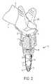
図1~10Bを参照すれば、1つの例示的な実施形態では、血液の付着流のための装置10、すなわち血液試料の流れを収集部位から収集容器まで案内し、制御するために血液試料が付着するための流れ方向付け付着部分を提供する装置は、通常、ハウジング12と、ハウジング12に取り外し可能に連結可能である収集容器14とを含む。容器14は、収集空洞70を画定し、内壁または内壁面72を含む。 Referring to FIGS. 1-10B, in one exemplary embodiment, the
図1~10Bを参照すれば、ハウジング12は、中心線CLを画定し、第1の端部20と、第2の端部22と、流れチャネル24とを含む。流れチャネル24は、入口26および出口28を含む。流れチャネル24の一部分、たとえば中央部分30は、ハウジング12の中心線CLからずらされる。これにより、流れチャネル24の出口28が容器14の内壁面72に隣接することが確実にされ、これは以下でより詳細に説明される。流れチャネル24はまた、入口26に第1の流れ方向付け付着部分32と、出口28に第2の流れ方向付け付着部分34とを含む。1つの実施形態では、流れチャネル24の出口28は、図1および2に示すようにハウジング12の第2の端部22を超えて延びている。 Referring to FIGS. 1-10B, the
図1および2を参照すれば、容器14がハウジング12に連結された状態で、流れチャネル24の出口28は、容器14の収集空洞70と流体連通しており、流れチャネル24の出口28は、容器14の内壁面72に隣接している。 Referring to FIGS. 1 and 2, with the
1つの実施形態では、ハウジング12の第1の端部20は、傾斜した壁面36を含む。このようにして、傾斜した壁面36は、第1の流れ方向付け付着部分32が上向きにそこから延びることを可能にする物理的構造、すなわち壁面を提供する。たとえば、図1を参照すれば、第1の流れ方向付け付着部分32は、傾斜した壁面36からハウジング12の入口26まで上向きに延びる。1つの実施形態では、傾斜した壁面38は、流れチャネル入口38を画定する。 In one embodiment, the
本開示の血液の付着流のための装置10は、収集部位から収集容器までの付着血流を確実にする、制御された血流路を提供する。本開示の血液の付着流のための装置10は、3つの重要な技術的要素を使用して血液の流れを所望の方法で制御することによってこれを達成する。第1に、血液試料を、患者の皮膚表面から第1の流れ方向付け付着部分を介して収集ハウジングまで制御し、案内する。第2に、血液試料を、収集ハウジングの第1の端部から毛細管移送によって収集ハウジングの第2の端部まで制御し、案内する。第3に、血液試料を、収集ハウジングの第2の端部から第2の流れ方向付け付着部分を介して収集容器の収集空洞内まで制御し、案内する。 The
たとえば、図2を参照すれば、ハウジング12の第1の端部20が血液源16と連通した状態で、第1の流れ方向付け付着部分32、流れチャネル24、第2の流れ方向付け付着部分34、および容器14の内壁面72は、付着部分を提供して、血液16の最初の液滴およびその後の血液16がハウジング12の第1の端部20から容器14の収集空洞70までたどるための付着血流を確立する。 For example, referring to FIG. 2, with the
第1の重要な血流路要素40は、血液16の最初の液滴を収集容器14に向かう方向に指Fの表面Sから離れるように方向付けることを伴う。1つの実施形態では、ハウジング12の第1の端部20が血液源16と連通した状態で、第1の流れ方向付け付着部分32は、柱を提供し、この柱に、血液16の最初の液滴が、制御された方法で、付着し、流下してハウジング12の流れチャネル24に入る。換言すれば、血液16の最初の液滴は、第1の流れ方向付け付着部分32に付着し、第1の流れ方向付け付着部分32から流れチャネル24に流れる。 The first important blood flow channel element 40 involves directing the first droplet of
1つの実施形態では、傾斜した壁面36は、第1の流れ方向付け付着部分32からハウジング12の流れチャネル24までの下向きの付着流路を提供する。血液16の最初の液滴が第1の流れ方向付け付着部分32に付着し、流下した後、その後の血液16は、血液16の最初の液滴の付着血流路をハウジング12の第1の端部20から容器14の収集空洞70までたどる。 In one embodiment, the sloping
第2の重要な血流路要素42は、血液16を、収集容器14に向かう方向に第2の流れ方向付け付着部分34まで流れチャネル24を下降するように方向付けることを伴う。たとえば、血液16の最初の液滴およびその後の血液16は、毛細管作用によって流れチャネル24を通って第2の流れ方向付け付着部分34まで引っ張られる。1つの実施形態では、流れチャネル24は、毛細管流れチャネルである。1つの実施形態では、流れチャネル24は、毛細管力を使用して、血液16を指Fの表面Sから離れるように引っ張って流れチャネル24を下降させる毛細管である。 The second important blood
第3の重要な血流路要素44は、血液16を流れチャネル24から収集容器14内に方向付けることを伴う。本開示の装置10により、付着流による流れチャネル24から容器14までの移行が確実になる。たとえば、血液16は、第2の流れ方向付け付着部分34および容器14の内壁面72に付着して、流れチャネル24から容器14の収集空洞70内に流れる。 A third important blood flow channel element 44 involves directing the
血液16を流れチャネル24から収集容器14内に方向付けることを伴う第3の重要な血流路要素44は、流れチャネル24の一部分、たとえば中央部分30がハウジング12の中心線CLからずらされることが重要であるという理由のために存在する。これにより、流れチャネル24の出口28、および第2の流れ方向付け付着部分34は、容器14の内壁面72に隣接して、流れチャネル24から容器14までの付着血流の移行が確実にされる。 A third important blood flow channel element 44, which involves directing the
血液16が付着する別の部分が見つかれば、血液16は流れチャネル24を流下して出て容器14内に入るだけである。第2の流れ方向付け付着部分34および容器14の内壁面72は、そのような付着部分を提供して、血液16を付着血流によって容器14の収集空洞70まで制御する。 If another portion to which the
上記で説明したように、付着血流のこの経路が確立されると、その後の血液16はこの付着血流をたどり、これに沿って流れる。上記で説明した方法で、本開示の装置10は、血液16の最初の液滴およびその後の血液16がハウジング12の第1の端部20から容器14の収集空洞70までたどるための付着血流を確立する。 As described above, once this pathway of adherent blood flow is established,
第1の流れ方向付け付着部分32は、図3~6に示すように多様な異なる設計および構造を含むことができる。第1の流れ方向付け付着部分32の追加の代替的な設計および構造が、企図される。たとえば、図3を参照すれば、1つの実施形態では、第1の流れ方向付け付着部分32は付着柱50である。付着柱50は、可変の直径および長さを有することができる単一の柱構造体である。柱50は、親水性表面特性を含んで、血液の最初の液滴を引き付け、第2の毛細管セクションまでの流路を確立することができる。1つの実施形態では、柱50は、0.25mmから4mmの間の直径と、2mmから20mmの間の長さを有することができる。 The first flow
図4を参照すれば、別の実施形態では、第1の流れ方向付け付着部分32は、複数の付着柱52である。複数の付着柱52は、多様な異なる数の柱を含む異なるサイズおよび構造体を有する柱を含むことができる。1つの構成では、複数の付着柱52は、血液の最初の液滴が、構造体の側部を汚すことなく、または望ましくない場所にたまることなく流路を確立するために複数の表面を提供する。複数の柱52はまた、個々の柱構造体間に作りだされた複数の毛細管セクションによって追加の毛細管現象を提供することもできる。1つの構成では、複数の付着柱52は、2本から10本の間の付着柱、たとえば5本から10本の間の付着柱を含むことができる。1つの実施形態では、各柱は、0.25mmから4mmの間の直径と、2mmから20mmの間の長さとを有することができる。 Referring to FIG. 4, in another embodiment, the first flow direction oriented
図5を参照すれば、別の実施形態では、第1の流れ方向付け付着部分32は、突起構造体54である。突起構造体54は、血液の付着流を案内し、異なる形状、サイズ、および構造体を含むことができる。この構成では、傾いた構造体は、血液の最初の液滴が付着し、第2の毛細管セクションまで案内されるための親水性表面を提供する。任意選択により、傾いた構造体の厚さは、約0.25から約5mmであってよい。 Referring to FIG. 5, in another embodiment, the first flow direction oriented
図6を参照すれば、別の実施形態では、第1の流れ方向付け付着部分32は、毛細管溝部分56である。毛細管溝部分56は、血液の付着流を案内し、異なる形状、サイズ、および数の溝を含むことができる。この構成では、溝を有する柱構造体は、溝内の表面が増大することによって毛細管力をより大きくすることを助け、それによって指から吸い取られる血液の最初の液滴を、第2の毛細管チャネルまで移送するための毛細管チャネルとして作用する。1つの構成では、設けられた溝の数は、1個から20個の間であってよく、各溝の直径は、0.25mmから1mmの間であってよい。 Referring to FIG. 6, in another embodiment, the first flow
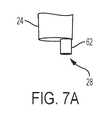
第2の流れ方向付け付着部分34は、図7A~10Bに示すように多様な異なる設計および構造体を含むことができる。第2の流れ方向付け付着部分34の追加の代替的な設計および構造体が、企図される。たとえば、図1および2を参照すれば、1つの実施形態では、第2の流れ方向付け付着部分34は、付着リップ60である。付着リップ60は、上記で説明したように容器14の収集空洞70内への付着血流を確立するように設計されたリップである。付着リップ60は、血液が膨張し、液滴を形成して収集空洞との付着を確立するための表面を提供する。 The second flow
図7Aおよび7Bを参照すれば、別の実施形態では、第2の流れ方向付け付着部分34は、延長された毛細管部分62である。1つの構成では、延長された毛細管部分は、2mmから10mmの間で流れチャネル24を超えて延びることができる。延長された毛細管部分62は、収集容器の壁から1mm未満の距離だけ離間することができる。 Referring to FIGS. 7A and 7B, in another embodiment, the second flow
図8Aおよび8Bを参照すれば、別の実施形態では、第2の流れ方向付け付着部分34は、内向きに湾曲したリップ64である。内向きに湾曲したリップ構造体は、ハウジングの一部分から収集空洞の表面までの血液の付着を助ける。1つの構成では、内向きに湾曲したリップ構造体は、流れチャネル24を超えて約0.5から約10mm延びることができる。 Referring to FIGS. 8A and 8B, in another embodiment, the second flow
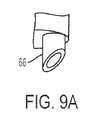
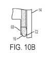
図9Aおよび9Bを参照すれば、別の実施形態では、第2の流れ方向付け付着部分34は、平坦な切断リップ66である。平坦な切断リップ66もまた、血滴を形成し、収集空洞の表面との血液の付着を確立することを助ける。1つの構成では、平坦な切断リップは、約10°から約80°の角度を有することができる。 Referring to FIGS. 9A and 9B, in another embodiment, the second flow
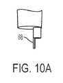
図10Aおよび10Bを参照すれば、別の実施形態では、第2の流れ方向付け付着部分34は、延長された柱構造体68である。1つの構成では、延長された柱構造体は、流れチャネル24を超えて約0.5mmから約10mmの距離だけ延びることができる。 Referring to FIGS. 10A and 10B, in another embodiment, the second flow
図1、2、17、および25A~28Bを参照すれば、本開示の収集容器14の例示的な実施形態が示される。容器14の追加の代替的な設計および構造が、企図される。本開示の収集容器14は、ハウジング12に取り外し可能に連結可能である。容器14は、収集空洞70を画定し、内壁または内壁面72を含む。図1および図2を参照すれば、容器14がハウジング12に連結された状態で、流れチャネル24の出口28は容器14の収集空洞70と流体連通しており、流れチャネル24の出口28は容器14の内壁面72に隣接している。1つの構成では、流れチャネル24の内径は、約0.5mmから約2mmであってよい。 Referring to FIGS. 1, 2, 17 and 25A-28B, exemplary embodiments of the
図25A~25Cを参照すれば、1つの実施形態では、容器14は、取り外し可能で連結可能なキャップ74と、繋ぎ要素76とを含む。そのような実施形態では、キャップ74は、容器14が図25Aに示したようにハウジング12に連結されたときに取り外される。繋ぎ要素76は、キャップ74が図25Bに示すように容器14の開放上端部78から連結解除された状態で、キャップ74が容器14の一部分に依然として固定されたままであることを確実にする。所望の量の血液16が容器14内に収集された後、容器14は、ハウジング12から取り外され、キャップ74は容器14に連結されて、図25Cに示すように血液16を保護するように容器14内に密封する。 Referring to FIGS. 25A-25C, in one embodiment, the
図26B~26Bを参照すれば、1つの実施形態では、容器14は、再密封可能なセプタム80を含む。そのような実施形態では、容器14がハウジング12に連結された状態で、流れチャネル24の一部分は、セプタム80を穿孔し、それによって流れチャネル24は容器14の収集空洞70と流体連通する。所望の量の血液16が容器14内に収集された後、容器14はハウジング12から取り外され、セプタム80は、自動的に再密封して閉じられ密封位置になり、図26Bに示すように血液16を保護するように容器14内に密封する。 Referring to FIGS. 26B-26B, in one embodiment, the
図27A~27Cを参照すれば、1つの実施形態では、容器14は、変形可能な投与部分82を含む。そのような実施形態では、容器14がハウジング12から取り外された状態で、血液16の一部分は、変形可能な部分82を動かすことによって容器14から投与され得る。たとえば、変形可能な部分82は、血液16が収集空洞70内に含まれる初期位置(図27A~27B)と、血液16の一部分が容器14の収集空洞70から排出される変形された位置(図27C)との間で移行可能である。変形可能な部分82は、圧迫されて初期位置(図27A~27B)から変形された位置(図27C)に移行する。このようにして、血液16は、医療施術者の血液試料への暴露を最小限に抑えながら、試料を分析するように意図された装置、たとえばポイントオブケア検査装置、カートリッジテスタ、または患者近くにおける検査装置などに移送され得る。1つの実施形態では、容器14はまた、端部キャップ84を含んで容器14の出口部分86を安全に密封する。ユーザが血液16の一部分を容器14から排出する準備ができたとき、端部キャップ84は、血液16を投与する前に、容器14の出口部分86から取り外される。 Referring to FIGS. 27A-27C, in one embodiment, the
図28A~28Bを参照すれば、1つの実施形態では、容器14は、延長チューブ88を含む。延長チューブ88は、分析器および分析装置と適合可能である。 Referring to FIGS. 28A-28B, in one embodiment, the
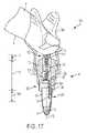
図17~24は、本開示の血液の付着流のための装置の別の例示的な実施形態を示す。図17~24を参照すれば、本開示の血液の付着流のための装置100は、収集部位から収集容器までの付着血流を確実にする、制御された血流路を提供する。 FIGS. 17-24 show another exemplary embodiment of the apparatus for adhering flow of blood of the present disclosure. Referring to FIGS. 17-24, the
ランセット装置を使用して患者の皮膚を穿刺すると、血液は指の表面上に広がり、留まる。血液および血液の流れを制御しない場合、血液は指の表面上に留まり、収集容器まで流れない。 When a patient's skin is punctured using a lancet device, blood spreads and stays on the surface of the finger. If the blood and blood flow are not controlled, the blood will stay on the surface of the finger and will not flow to the collection vessel.
図17~24を参照すれば、1つの例示的な実施形態では、血液の付着流のための装置100は、通常、ハウジング112と、ハウジング112に取り外し可能に連結可能である収集容器14とを含む。容器14は、収集空洞70を画定し、内壁または内壁面72を含む。図1~10Bを参照して上記で説明した装置10と適合可能な同じ容器14は、図17~24を参照して説明した装置100と適合可能である。 With reference to FIGS. 17-24, in one exemplary embodiment, the
図17を参照すれば、ハウジング112は、中心線CLを画定し、第1の端部120と、第2の端部122と、中空針123と、流れチャネル124とを含む。流れチャネル24は、入口126および出口128を含む。流れチャネル124の一部分、たとえば底部分130は、ハウジング112の中心線CLからずらされる。これにより、流れチャネル124の出口128が容器14の内壁面72に隣接することが確実にされ、これは以下でより詳細に説明される。流れチャネル124はまた、出口128に流れ方向付け付着部分134を含む。1つの実施形態では、流れチャネル124の出口128は、図17に示すようにハウジング112の第2の端部122を超えて延びている。1つの実施形態では、中空針123は、ハウジング112の第1の端部120と流れチャネル124との間にある。 Referring to FIG. 17,
図17~24に示す実施形態では、中空針123は、図1~10Bに示す装置10に関して上記で説明した第1の流れ方向付け付着部分32と同様に機能する。
3In the embodiments shown in FIGS. 17 to 24, the
3
図17を参照すれば、容器14がハウジング112に連結された状態で、流れチャネル124の出口128は容器14の収集空洞70と流体連通しており、流れチャネル124の出口128は容器14の内壁面72に隣接している。 Referring to FIG. 17, with the
ランセット装置を使用して患者の皮膚を穿刺すると、血液は指の表面上に広がり、留まる。血液および血液の流れを制御しない場合、血液は指の表面上に留まり、収集容器まで流れない。 When a patient's skin is punctured using a lancet device, blood spreads and stays on the surface of the finger. If the blood and blood flow are not controlled, the blood will stay on the surface of the finger and will not flow to the collection vessel.
本開示の血液の付着流のための装置100は、収集部位から収集容器までの付着血流を確実にする、制御された血流路を提供する。本開示の血液の付着流のための装置100は、3つの重要な技術的要素を使用して血液の流れを所望の方法で制御することによってこれを達成する。 The
たとえば、図17を参照すれば、ハウジング112の第1の端部120が血液源16と連通した状態で、中空針123、流れチャネル124、流れ方向付け付着部分134、および容器14の内壁面72は、付着部分を提供して、血液16の最初の液滴およびその後の血液16がハウジング112の第1の端部120から容器14の収集空洞70までたどるための付着血流を確立する。 For example, referring to FIG. 17, with the
第1の重要な血流路要素140は、血液16の最初の液滴を収集容器14に向かう方向に指Fの表面Sから離れるように方向付けることを伴う。1つの実施形態では、ハウジング112の第1の端部120が血液源16と連通した状態で、血液16の最初の液滴は、中空針123の一部分に付着し、図17に示すように制御された方法で中空針123を通って流れチャネル124に流れる。 The first important blood
このようにして、中空針123の一部分は、図1~10Bに示す装置10に関して上記で説明した第1の流れ方向付け付着部分32と同様に機能する付着部分を提供する。中空針123を含む本開示の装置100は、この中空針123を使用して指Fの皮膚表面Sを突いて血液源16を提供することもできるという点において利点を提供する。そのような実施形態では、別個のランセット装置は必要とされない。たとえば、1つの実施形態では、中空針123は、指Fの皮膚表面Sを突いて血液源16を提供するために使用することができるランシングブレード151を含むことができる。そのような実施形態では、ハウジング112の第1の端部120が血液源16と連通した状態で、血液16の最初の液滴、およびその後の血液16は、ランシングブレード151に付着し、中空針123を通って流れチャネル124に流れる。 In this way, the portion of the
血液16の最初の液滴が中空針123の一部分に付着し、中空針123を通って流れた後、その後の血液16は、血液16の最初の液滴の付着血流路をハウジング112の第1の端部120から容器14の収集空洞70までたどる。 After the first droplet of
第2の重要な血流路要素142は、毛細管作用によって流れ方向付け付着部分134まで流れチャネル124を通るように血液16を方向付けるか、または血液16を引っ張ることを伴う。1つの実施形態では、第2の重要な血流路要素142は、収集容器14に向かう方向に毛細管作用によって流れ方向付け付着部分134まで中空針123および流れチャネル124を通るように血液16を方向付けるか、または血液16を引っ張ることを伴う。たとえば、血液16の最初の液滴、およびその後の血液16は、毛細管作用によって流れチャネル124を通って流れ方向付け付着部分134まで引っ張られる。1つの実施形態では、流れチャネル124は、毛細管流れチャネルである。1つの実施形態では、流れチャネル124は、毛細管力を使用して、血液16を指Fの表面Sから離れるように引っ張って流れチャネル124を下降させる毛細管である。 The second important blood
1つの実施形態では、ハウジング112は、傾斜した壁面136を中空針123と流れチャネル124との間に含む。1つの実施形態では、傾斜した壁面138は、流れチャネル入口138を画定する。1つの実施形態では、傾斜した壁面136は、中空針123からハウジング112の流れチャネル124までの下向きの付着流路を提供する。 In one embodiment, the
第3の重要な血流路要素144は、血液16を流れチャネル124から収集容器14内に方向付けることを伴う。本開示の装置100は、付着流による流れチャネル124から容器14までの移行を確実にする。たとえば、血液16は、流れ方向付け付着部分134および容器14の内壁面72に付着して、流れチャネル124から容器14の収集空洞70内に流れる。 A third important blood
血液16を流れチャネル124から収集容器14内に方向付けることを伴う第3の重要な血流路要素144は、流れチャネル124の一部分、たとえば底部分130が、ハウジング112の中心線CLからずらされることが重要であるという理由のために存在する。これにより、流れチャネル124の出口128および流れ方向付け付着部分134が、容器14の内壁面72に隣接して、流れチャネル124から容器14までの付着血流の移行を確実にすることが、確実となる。 A third important blood
血液16が付着する別の部分が見つかれば、血液16は流れチャネル124を流下して出て容器14内に入るだけである。流れ方向付け付着部分134および容器14の内壁面72は、そのような付着部分を提供して、血液16を付着血流によって容器14の収集空洞70まで制御する。 If another portion to which the
上記で説明したように、付着血流のこの経路が確立されると、その後の血液16は、この付着血流をたどり、これに沿って流れる。上記で説明した方法では、本開示の装置100は、血液16の最初の液滴およびその後の血液16がハウジング112の第1の端部120から容器14の収集空洞70までたどるための付着血流を確立する。 As described above, once this pathway of adherent blood flow is established,
上記で論じたように、血液16の流れのための付着部分を提供する中空針123の一部分は、図1~10Bに示す装置10に関して上記で説明した第1の流れ方向付け付着部分32と同様に機能する。 As discussed above, the portion of the
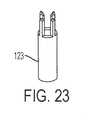
中空針123は、図18~24に示すような多様な異なる設計および構造体を含むことができる。中空針123の追加の代替的な設計および構造体が、企図される。たとえば、図18および19を参照すれば、1つの実施形態では、中空針123は、ベベル切断された中空針を含む。1つの構成では、針のベベルは、3mmから6mmの間の長さであってよく、管腔内径は、0.25mmから4mmの間であってよい。 The
上記で論じたように、図20および21を参照すれば、1つの実施形態では、中空針123は、指Fの皮膚表面Sを突いて血液源16を提供するために使用することができるランシングブレード151を含むことができる。 As discussed above, with reference to FIGS. 20 and 21, in one embodiment the
図21を参照すれば、別の実施形態では、中空針123は、中空針123の周りに流れ方向付けリング155を含む。流れ方向付けリング155は、血液16が中空針123を流下することを防止し、血液16が中空針123を通って流れチャネル124に流れることを確実にする。図22~24は、中空針123の追加の代替的な設計および構造体を示す。針ベベルは、追加の第1の、流れが方向付けられた付着セクションとして、図3を参照して上記で説明した柱構造体部分32と同様に働く。 Referring to FIG. 21, in another embodiment, the
流れ方向付け付着部分134は、図7A~10Bに示すような多様な異なる設計および構造体を含むことができる。流れ方向付け付着部分134の追加の代替的な設計および構造体が、企図される。装置100の流れ方向付け付着部分134は、上記で説明し、図7A~10Bに示した装置10の第2の流れ方向付け付着部分34と同じ設計および構造体を含むことができる。 The flow
本開示の装置10、100の別の利点は、装置10、100が血液試料16内に試料安定剤200の分散された混合を実施できることである。図11および12を参照すれば、1つの実施形態では、試料安定剤200は、流れチャネル24、124の一部分内に配置され、それにより、血液試料16は、制御された付着血流を血液試料16が収集部位から本開示の収集容器までたどるときに、試料安定剤200を通過するようになる。このようにして、血液試料16は、装置10、100の一部分内に提供された、抗凝血剤または他の添加剤などの試料安定剤200と混合され得る。試料安定剤200は、抗凝血剤とすることができ、またはたとえば、RNA、タンパク質検体、または他の要素などの、血液内に特有の要素を保存するように設計された物質とすることができる。 Another advantage of the
図11および12を参照すれば、1つの実施形態では、試料安定剤200は、孔204と、材料202のこの孔204内にある乾燥抗凝血剤粉末206とを含む材料202を含む。このようにして、装置10、100は、流れチャネル24、124の一部分上またはその中に堆積された、ヘパリンまたはEDTAなどの乾燥抗凝血剤を含むことができる。1つの実施形態では、材料202は、連続気泡発泡体であり、連続気泡発泡体の気泡内に分散された乾燥抗凝血剤を含んで、流入混合および抗凝血剤の取り入れの効果を促進する。1つの実施形態では、試料安定剤200は、乾燥抗凝血剤粉末206である。 Referring to FIGS. 11 and 12, in one embodiment the
1つの実施形態では、連続気泡発泡体は、抗凝血剤によって処理されて、連続気泡発泡体の孔204にわたって細かく分散された乾燥抗凝血剤粉末206を形成することができる。血液試料16が流れチャネル24、124を通って流れるとき、血液試料16は、連続気泡発泡体を通過し、連続気泡発泡体の内部孔構造にわたって利用できる抗凝血剤粉末206に露出される。このようにして、血液試料16は、材料202または連続気泡発泡体を通過しながら、溶解し、乾燥抗凝血剤粉末206と混合する。 In one embodiment, the open cell foam can be treated with an anticoagulant to form a dry
連続気泡発泡体は、たとえば、BASFから市販されているBasotect(登録商標)発泡体などのメラミン樹脂発泡体などの、血液に不活性である軟質の変形可能な連続気泡発泡体とすることができ、またはホルムアルデヒド-メラミン-重亜硫酸ナトリウムコポリマーからなることができる。連続気泡発泡体は、熱および有機溶剤に対して実質的に耐性を有する可撓性の親水性連続気泡発泡体であってもよい。1つの実施形態では、発泡体は、スポンジ材料を含むことができる。 The open cell foam can be a soft, deformable open cell foam that is inactive to blood, such as a melamine resin foam such as Formaldehyde® foam commercially available from BASF. , Or can consist of a formaldehyde-melamine-sodium bicarbonate copolymer. The open cell foam may be a flexible hydrophilic open cell foam that is substantially resistant to heat and organic solvents. In one embodiment, the foam can include a sponge material.
抗凝血剤または他の添加剤は、発泡体を添加剤および水の液体溶液に浸し、その後水分を蒸発させて発泡体の内部構造にわたって細かく分散された乾燥添加剤粉末を形成することによって、連続気泡発泡体内に導入され得る。 The anticoagulant or other additive is by immersing the foam in a liquid solution of the additive and water and then evaporating the water to form a dry additive powder that is finely dispersed over the internal structure of the foam. Can be introduced into open cell foam.
図13~16は、容器14内に含まれる試料安定剤200の例示的な実施形態を示す。 FIGS. 13-16 show exemplary embodiments of the
たとえば、図13を参照すれば、1つの実施形態では、抗凝血剤凍結乾燥球210が容器14の収集空洞70内に提供される。血液16が本開示の付着流をたどって容器14内に入るとき、抗凝血剤凍結乾燥球210は、血液16と接触したときに血液16内に溶解する。 For example, referring to FIG. 13, in one embodiment, the anticoagulant freeze-dried
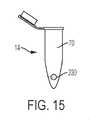
図14を参照すれば、別の実施形態では、試料安定剤200は、浮遊する抗凝血剤でコーティングされた連続気泡発泡体材料220を含む。図15を参照すれば、別の実施形態では、試料安定剤200は、浮遊する抗凝血剤でコーティングされた浮遊ボール230を含む。図16を参照すれば、別の実施形態では、容器14は、抗凝血剤でコーティングされた壁面240および混合ボール242を含む。 Referring to FIG. 14, in another embodiment, the
本開示を例示的な設計を有するものとして説明してきたが、本開示の趣旨および範囲内で本開示をさらに改変することができる。したがって、本出願は、その一般的原則を使用して本開示の任意の変形形態、使用、または適用を対象とするように意図される。さらに、本出願は、本開示が関係する当技術分野において知られているか、または慣習的な実践に含まれるような、かつ付属の特許請求の範囲の制限内に含まれる、本開示からのそのような逸脱を対象とするように意図される。 Although the present disclosure has been described as having an exemplary design, the present disclosure may be further modified within the spirit and scope of the present disclosure. Accordingly, this application is intended to cover any variation, use, or application of the present disclosure using its general principles. In addition, the application is from this disclosure as it is known in the art to which this disclosure relates, or is included in conventional practice, and is within the limits of the appended claims. Intended to target such deviations.
Claims (15)
Translated fromJapanese中心線を画定し、第1の端部と、第2の端部と、入口および出口を有する流れチャネルとを有するハウジングであって、前記流れチャネルの一部分は、前記ハウジングの前記中心線からずらされ、前記流れチャネルは、前記入口に隣接する第1の流れ方向付け付着部分と、前記出口に隣接する第2の流れ方向付け付着部分とを有する、ハウジングと、
前記ハウジングに取り外し可能に連結可能な容器であって、収集空洞を画定し、内壁を有する容器と
を備え、
前記容器が前記ハウジングに連結された状態で、前記流れチャネルの前記出口は、前記容器の前記収集空洞と流体連通しており、前記流れチャネルの前記出口は、前記容器の前記内壁に隣接しており、
前記ハウジングの前記第1の端部は、傾斜した壁面を含み、
前記第1の流れ方向付け付着部分は、付着柱であり、全体が前記中心線に沿って前記傾斜した壁面から延び、
前記第2の流れ方向付け付着部分は、前記流れチャネルから前記収集空洞までの血流を確立するように構成される装置。A device for adhering blood flow
A housing that defines a centerline and has a first end, a second end, and a flow channel with inlets and outlets, wherein a portion of the flow channel is offset from the centerline of the housing. The flow channel comprises a housing having a first flow directional attachment portion adjacent to the inlet and a second flow directional attachment portion adjacent to the outlet.
A container that is removable and connectable to the housing, comprising a container that defines a collection cavity and has an inner wall.
With the container connected to the housing, the outlet of the flow channel is in fluid communication with the collection cavity of the container, and the outlet of the flow channel is adjacent to the inner wall of the container.Ori,
The first end of the housing includes a sloping wall surface.
The first flow-direction attachment portion is an attachment column, which extends from the inclined wall surface along the center line as a whole.
The second flow directional attachment portion is a device configured to establish blood flow from the flow channel to the collection cavity .
置。The device according to claim 1, wherein the second flow direction attachment portion is an extended capillary portion.
Priority Applications (3)
| Application Number | Priority Date | Filing Date | Title |
|---|---|---|---|
| JP2022097391AJP7586857B2 (en) | 2016-08-24 | 2022-06-16 | Apparatus for the adhesion flow of blood |
| JP2023193039AJP7620069B2 (en) | 2016-08-24 | 2023-11-13 | Apparatus for the adhesion flow of blood |
| JP2025003692AJP2025061177A (en) | 2016-08-24 | 2025-01-09 | Apparatus for the adhesion flow of blood |
Applications Claiming Priority (3)
| Application Number | Priority Date | Filing Date | Title |
|---|---|---|---|
| US201662378971P | 2016-08-24 | 2016-08-24 | |
| US62/378,971 | 2016-08-24 | ||
| PCT/US2017/048147WO2018039307A1 (en) | 2016-08-24 | 2017-08-23 | A device for the attached flow of blood |
Related Child Applications (1)
| Application Number | Title | Priority Date | Filing Date |
|---|---|---|---|
| JP2022097391ADivisionJP7586857B2 (en) | 2016-08-24 | 2022-06-16 | Apparatus for the adhesion flow of blood |
Publications (2)
| Publication Number | Publication Date |
|---|---|
| JP2019524379A JP2019524379A (en) | 2019-09-05 |
| JP7092747B2true JP7092747B2 (en) | 2022-06-28 |
Family
ID=59746370
Family Applications (8)
| Application Number | Title | Priority Date | Filing Date |
|---|---|---|---|
| JP2019511433AActiveJP7104026B2 (en) | 2016-08-24 | 2017-08-23 | Device for taking blood samples |
| JP2019511425AActiveJP7092747B2 (en) | 2016-08-24 | 2017-08-23 | Device for adhering blood flow |
| JP2022097391AActiveJP7586857B2 (en) | 2016-08-24 | 2022-06-16 | Apparatus for the adhesion flow of blood |
| JP2022109845AActiveJP7368555B2 (en) | 2016-08-24 | 2022-07-07 | Device for obtaining blood samples |
| JP2023176633AActiveJP7629497B2 (en) | 2016-08-24 | 2023-10-12 | Apparatus for obtaining blood samples |
| JP2023193039AActiveJP7620069B2 (en) | 2016-08-24 | 2023-11-13 | Apparatus for the adhesion flow of blood |
| JP2025003692APendingJP2025061177A (en) | 2016-08-24 | 2025-01-09 | Apparatus for the adhesion flow of blood |
| JP2025014987APendingJP2025062007A (en) | 2016-08-24 | 2025-01-31 | Apparatus for obtaining blood samples |
Family Applications Before (1)
| Application Number | Title | Priority Date | Filing Date |
|---|---|---|---|
| JP2019511433AActiveJP7104026B2 (en) | 2016-08-24 | 2017-08-23 | Device for taking blood samples |
Family Applications After (6)
| Application Number | Title | Priority Date | Filing Date |
|---|---|---|---|
| JP2022097391AActiveJP7586857B2 (en) | 2016-08-24 | 2022-06-16 | Apparatus for the adhesion flow of blood |
| JP2022109845AActiveJP7368555B2 (en) | 2016-08-24 | 2022-07-07 | Device for obtaining blood samples |
| JP2023176633AActiveJP7629497B2 (en) | 2016-08-24 | 2023-10-12 | Apparatus for obtaining blood samples |
| JP2023193039AActiveJP7620069B2 (en) | 2016-08-24 | 2023-11-13 | Apparatus for the adhesion flow of blood |
| JP2025003692APendingJP2025061177A (en) | 2016-08-24 | 2025-01-09 | Apparatus for the adhesion flow of blood |
| JP2025014987APendingJP2025062007A (en) | 2016-08-24 | 2025-01-31 | Apparatus for obtaining blood samples |
Country Status (13)
| Country | Link |
|---|---|
| US (5) | US11771352B2 (en) |
| EP (7) | EP3503806B1 (en) |
| JP (8) | JP7104026B2 (en) |
| KR (4) | KR102460682B1 (en) |
| CN (4) | CN115192014B (en) |
| AU (4) | AU2017315323B2 (en) |
| BR (2) | BR112019003638A2 (en) |
| CA (2) | CA3034842A1 (en) |
| ES (4) | ES2834078T3 (en) |
| MX (4) | MX2019002218A (en) |
| PL (1) | PL3503807T3 (en) |
| RU (4) | RU2747438C2 (en) |
| WO (2) | WO2018039305A1 (en) |
Families Citing this family (34)
| Publication number | Priority date | Publication date | Assignee | Title |
|---|---|---|---|---|
| US20100256524A1 (en) | 2009-03-02 | 2010-10-07 | Seventh Sense Biosystems, Inc. | Techniques and devices associated with blood sampling |
| US20130158482A1 (en) | 2010-07-26 | 2013-06-20 | Seventh Sense Biosystems, Inc. | Rapid delivery and/or receiving of fluids |
| WO2012021801A2 (en) | 2010-08-13 | 2012-02-16 | Seventh Sense Biosystems, Inc. | Systems and techniques for monitoring subjects |
| WO2012064802A1 (en) | 2010-11-09 | 2012-05-18 | Seventh Sense Biosystems, Inc. | Systems and interfaces for blood sampling |
| CN103874461B (en) | 2011-04-29 | 2017-05-10 | 第七感生物系统有限公司 | Devices for collecting and/or manipulating blood spots or other bodily fluids |
| WO2019067567A1 (en)* | 2017-09-26 | 2019-04-04 | Juno Diagnostics, Inc. | Devices, systems and methods for biomarker analysis |
| US20190099117A1 (en)* | 2017-10-02 | 2019-04-04 | Reliant Immune Diagnostics, Inc | Finger cuff having vibration mechanism for use in performing a finger prick |
| CA3080117A1 (en) | 2017-10-27 | 2019-05-02 | Juno Diagnostics, Inc. | Devices, systems and methods for ultra-low volume liquid biopsy |
| JP6905953B2 (en)* | 2018-05-15 | 2021-07-21 | 富士フイルム株式会社 | Blood sample guide device and blood test kit |
| EP3801259B1 (en)* | 2018-05-25 | 2023-07-19 | Becton, Dickinson and Company | Blood collection assembly with vibration module |
| BR112021004090A2 (en)* | 2018-09-06 | 2021-05-25 | Becton, Dickinson And Company | arterial blood gas collection system |
| BR112021015617A2 (en)* | 2019-02-14 | 2021-10-05 | Becton, Dickinson And Company | CAPILLARY COLLECTOR WITH ROTATING CONNECTION |
| BE1027338B1 (en)* | 2019-06-04 | 2021-01-14 | Inst Of Tropical Medicine | FINGER PRICKER COLLECTOR |
| JP7157711B2 (en)* | 2019-07-19 | 2022-10-20 | 株式会社日立ハイテク | Blood collection device |
| WO2021061751A1 (en) | 2019-09-23 | 2021-04-01 | Gateway Genomics, Llc | Methods, compositions, and kits for determining the sex of a fetus |
| WO2021091380A1 (en)* | 2019-11-07 | 2021-05-14 | Stichting Het Nederlands Kanker Instituut-Antoni van Leeuwenhoek Ziekenhuis | Blood collection device and method for the self-collection of blood by a user |
| JP2023527642A (en)* | 2020-03-31 | 2023-06-30 | プレシヘルス エスアー | Bodily fluid collection device and method of use |
| GB202004718D0 (en)* | 2020-03-31 | 2020-05-13 | Osler Diagnostics Ltd | Capillary blood sampling |
| WO2022043748A2 (en)* | 2020-08-23 | 2022-03-03 | Preci Health Sa | Capillary blood sampling device and method of use |
| GB2598334B (en) | 2020-08-26 | 2022-11-30 | Mowgli Innovations Ltd | Finger receptacle and holding device |
| CN117580506A (en)* | 2021-06-29 | 2024-02-20 | 贝克顿·迪金森公司 | capillary blood collection device |
| WO2023278234A1 (en)* | 2021-06-29 | 2023-01-05 | Becton, Dickinson And Company | Capillary blood collection device |
| CN117597069A (en) | 2021-06-29 | 2024-02-23 | 贝克顿·迪金森公司 | Simulation device for capillary blood collection |
| WO2023278225A1 (en)* | 2021-06-29 | 2023-01-05 | Becton, Dickinson And Company | Capillary blood collection device |
| CN117597195A (en)* | 2021-06-29 | 2024-02-23 | 贝克顿·迪金森公司 | Sample container for capillary blood collection |
| KR20240024243A (en)* | 2021-06-29 | 2024-02-23 | 백톤 디킨슨 앤드 컴퍼니 | Capillary Blood Collection Device |
| US20240315619A1 (en)* | 2021-06-29 | 2024-09-26 | Becton, Dickinson And Company | Blood Collection Kit With Blood Collection Devices of Multiple Sizes and Associated Sizing Systems and Methods |
| EP4362791A4 (en)* | 2021-06-29 | 2025-04-30 | Becton, Dickinson and Company | Capillary blood collection device |
| KR20240024244A (en)* | 2021-06-29 | 2024-02-23 | 백톤 디킨슨 앤드 컴퍼니 | Capillary Blood Collection Device |
| JP2024538133A (en)* | 2021-10-15 | 2024-10-18 | ベクトン・ディキンソン・アンド・カンパニー | Additive mix for blood sample collection |
| US11957465B2 (en) | 2022-08-23 | 2024-04-16 | Reddrop Dx, Inc. | Accelerated ergonomic collection of capillary blood |
| BE1030990B1 (en)* | 2022-10-25 | 2024-05-28 | Inst Voor Tropische Geneeskunde | BLOOD SAMPLING DEVICE FOR COLLECTION OF A BLOOD SAMPLE FROM A FINGER OR TOE |
| EP4491118A1 (en) | 2023-07-13 | 2025-01-15 | Becton, Dickinson and Company | Collector accessory for small volume collection containers and related sample collection methods |
| WO2025064983A1 (en)* | 2023-09-21 | 2025-03-27 | Becton, Dickinson And Company | Lancing finger sleeve |
Citations (3)
| Publication number | Priority date | Publication date | Assignee | Title |
|---|---|---|---|---|
| JP2008011880A (en) | 2006-06-30 | 2008-01-24 | Sakae:Kk | Liquid collector |
| JP2011513754A (en) | 2008-03-05 | 2011-04-28 | ベクトン・ディキンソン・アンド・カンパニー | Capillary action collection device and container assembly |
| JP2014530053A (en) | 2011-09-22 | 2014-11-17 | サノフィ−アベンティス・ドイチュラント・ゲゼルシャフト・ミット・ベシュレンクテル・ハフツング | How to draw a blood sample |
Family Cites Families (157)
| Publication number | Priority date | Publication date | Assignee | Title |
|---|---|---|---|---|
| US2646799A (en) | 1951-02-14 | 1953-07-28 | Jr George W Jacoby | Blood lancet |
| CH500707A (en)* | 1968-07-26 | 1970-12-31 | Micromedic Systems Inc | Device for performing percutaneous and digital blood sampling |
| CH522395A (en)* | 1968-07-26 | 1972-05-15 | Micromedic Systems Inc | Test tube intended for percutaneous and digital blood sampling |
| US3630191A (en) | 1969-02-27 | 1971-12-28 | Gilford Instr Labor Inc | Apparatus and method for filling capillary tubing with fluids |
| CH538277A (en) | 1970-09-04 | 1973-06-30 | Micromedic Systems Inc | Percutaneous blood test device |
| US4024857A (en) | 1974-12-23 | 1977-05-24 | Becton, Dickinson And Company | Micro blood collection device |
| JPS51122982A (en)* | 1974-12-23 | 1976-10-27 | Becton Dickinson Co | Small blood sampling unit |
| US4411163A (en) | 1981-07-27 | 1983-10-25 | American Hospital Supply Corporation | Ventable sample collection device |
| US4397318A (en) | 1981-08-10 | 1983-08-09 | Becton Dickinson And Company | Blood collector for microcollection container |
| US4620549A (en) | 1985-01-25 | 1986-11-04 | Becton, Dickinson And Company | Blood collection assembly |
| US4646753A (en) | 1985-06-11 | 1987-03-03 | Becton, Dickinson And Company | Blood collector for microcollection container |
| DE3541041A1 (en)* | 1985-11-19 | 1987-05-21 | Sarstedt Kunststoff | BLOOD COLLECTOR |
| US4690153A (en)* | 1985-11-29 | 1987-09-01 | Becton, Dickinson And Company | Flow inducing means for small volume containers |
| US4791938A (en) | 1987-11-16 | 1988-12-20 | Nanci Van Valkenburg | Capillary blood collector and method |
| US5014718A (en) | 1988-01-22 | 1991-05-14 | Safety Diagnostics, Inc. | Blood collection and testing method |
| US5070886A (en) | 1988-01-22 | 1991-12-10 | Safety Diagnostice, Inc. | Blood collection and testing means |
| DE4000968C1 (en)* | 1990-01-16 | 1991-06-20 | Dieter 2090 Drage De Wendelborn | Blood sampling apparatus - has blood observation chamber mounted in sampling vessel stopper |
| US5309924A (en)* | 1992-04-29 | 1994-05-10 | Peabody Alan M | Spill-proof blood collection device |
| US5384096A (en) | 1993-05-12 | 1995-01-24 | Becton, Dickinson And Company | Microcollection tube assembly |
| HU219921B (en) | 1993-10-20 | 2001-09-28 | Ervin Lipscher | Device for making blood test, especially from fingers |
| US5485856A (en) | 1994-04-22 | 1996-01-23 | Buckland; Peter E. | Hand immobilizing and positioning apparatus for x-ray examinations |
| JPH08317918A (en) | 1995-05-25 | 1996-12-03 | Advance Co Ltd | Blood drawing device |
| US5569223A (en) | 1995-06-06 | 1996-10-29 | Home Access Health Corporation | Apparatus and method for enhancing blood flow to obtain a blood sample |
| DE29514084U1 (en) | 1995-09-01 | 1995-11-02 | Biosafe Diagnostics Corp., Lincolnshire, Ill. | Blood collection and test device |
| US5662127A (en) | 1996-01-17 | 1997-09-02 | Bio-Plas, Inc. | Self-contained blood withdrawal apparatus and method |
| US5714125A (en) | 1996-03-07 | 1998-02-03 | Medical Safety Products, Inc. | Device for collecting a blood sample from a plastic segment tube |
| US20020010406A1 (en) | 1996-05-17 | 2002-01-24 | Douglas Joel S. | Methods and apparatus for expressing body fluid from an incision |
| US5951493A (en) | 1997-05-16 | 1999-09-14 | Mercury Diagnostics, Inc. | Methods and apparatus for expressing body fluid from an incision |
| US5951492A (en) | 1996-05-17 | 1999-09-14 | Mercury Diagnostics, Inc. | Methods and apparatus for sampling and analyzing body fluid |
| EP1579814A3 (en) | 1996-05-17 | 2006-06-14 | Roche Diagnostics Operations, Inc. | Methods and apparatus for sampling and analyzing body fluid |
| EP1862116A3 (en) | 1996-05-17 | 2009-02-25 | Roche Diagnostics Operations, Inc. | Disposable element for use in a body fluid sampling device |
| US5857983A (en) | 1996-05-17 | 1999-01-12 | Mercury Diagnostics, Inc. | Methods and apparatus for sampling body fluid |
| US6706000B2 (en) | 1997-11-21 | 2004-03-16 | Amira Medical | Methods and apparatus for expressing body fluid from an incision |
| US6086545A (en) | 1998-04-28 | 2000-07-11 | Amira Medical | Methods and apparatus for suctioning and pumping body fluid from an incision |
| JP4210782B2 (en) | 1999-10-13 | 2009-01-21 | アークレイ株式会社 | Blood sampling position indicator |
| DE10026172A1 (en) | 2000-05-26 | 2001-11-29 | Roche Diagnostics Gmbh | Body fluid withdrawal system |
| DE10026170A1 (en)* | 2000-05-26 | 2001-12-06 | Roche Diagnostics Gmbh | Body fluid withdrawal system |
| RU2269954C2 (en) | 2000-06-09 | 2006-02-20 | Дайэбитиз Дайэгностикс, Инк. | Cap for lancet device for punching dermal tissue (versions), cap for lancet device for punching tip of finger, cap for lancet device for punching curvilinear dermal tissue and lancet device for punching dermal tissue |
| US6551267B1 (en) | 2000-10-18 | 2003-04-22 | Becton, Dickinson And Company | Medical article having blood-contacting surface |
| KR100788305B1 (en) | 2001-01-12 | 2007-12-27 | 아크레이 인코퍼레이티드 | Puncture device, its manufacture method, pump mechanism and suction device |
| JP2002219115A (en) | 2001-01-26 | 2002-08-06 | Matsushita Electric Works Ltd | Blood collecting device |
| US20040092843A1 (en) | 2001-02-22 | 2004-05-13 | Doron Kreiser | Device and method for measuring fetal blood pH |
| US20020188223A1 (en) | 2001-06-08 | 2002-12-12 | Edward Perez | Devices and methods for the expression of bodily fluids from an incision |
| US7749174B2 (en) | 2001-06-12 | 2010-07-06 | Pelikan Technologies, Inc. | Method and apparatus for lancet launching device intergrated onto a blood-sampling cartridge |
| JP2003070771A (en) | 2001-09-07 | 2003-03-11 | Omron Corp | Equipment and system for organism information measurement and method of organism information measurement management |
| CA2461370A1 (en) | 2001-09-26 | 2003-05-15 | F. Hoffmann-La Roche Ag | Method and apparatus for sampling bodily fluid |
| US20030212344A1 (en)* | 2002-05-09 | 2003-11-13 | Vadim Yuzhakov | Physiological sample collection devices and methods of using the same |
| USD488588S1 (en) | 2002-12-13 | 2004-04-13 | James P. Murphy | Finger accessory appliance |
| US20040127818A1 (en) | 2002-12-27 | 2004-07-01 | Roe Steven N. | Precision depth control lancing tip |
| GB0301587D0 (en)* | 2003-01-23 | 2003-02-26 | Epsom & St Helier Nhs Trust | A lancet holding device |
| WO2004078041A2 (en) | 2003-02-13 | 2004-09-16 | Toru Nakayama | Painless blood-collecting method |
| DE10315396A1 (en)* | 2003-04-04 | 2004-10-14 | Lieblein, Martin, Dr. | Automatic blood sugar monitor and warning system, for hypo- and hyperglycemia, has a finger stall containing the electromagnetic pricker and test strips with a glucose enzyme linked to a control |
| USD488232S1 (en) | 2003-06-30 | 2004-04-06 | Nanma Ltd. | Finger massager |
| DE10332283A1 (en) | 2003-07-16 | 2005-02-03 | Roche Diagnostics Gmbh | System for taking body fluid |
| DE10332488A1 (en) | 2003-07-16 | 2005-02-24 | Roche Diagnostics Gmbh | Analyzer and analysis method for body fluids |
| JP2005094425A (en) | 2003-09-18 | 2005-04-07 | Fuji Xerox Co Ltd | Remote control device |
| JP4484669B2 (en) | 2003-10-29 | 2010-06-16 | アークレイ株式会社 | Puncture device |
| JP4762341B2 (en) | 2003-10-29 | 2011-08-31 | アークレイ株式会社 | Puncture device |
| JP4621850B2 (en) | 2003-10-29 | 2011-01-26 | アークレイ株式会社 | Squeezing tool and puncture device |
| GB2409411A (en)* | 2003-12-22 | 2005-06-29 | William Thomas Dennis Bates | Blood collection system |
| WO2005077274A1 (en)* | 2004-02-06 | 2005-08-25 | Bayer Healthcare Llc | Method and apparatus for measuring an analyte in a body fluid |
| US7201723B2 (en) | 2004-03-25 | 2007-04-10 | Roche Diagnostics Operations, Inc. | Pulsating expression cap |
| US20050215923A1 (en) | 2004-03-26 | 2005-09-29 | Wiegel Christopher D | Fingertip conforming fluid expression cap |
| CA2562215A1 (en) | 2004-04-10 | 2005-10-20 | F. Hoffmann-La Roche Ag | Method and system for taking body fluid |
| US20050234488A1 (en) | 2004-04-16 | 2005-10-20 | John Allen | Saddle-contoured cap for a dermal tissue lancing device |
| US20050234486A1 (en) | 2004-04-16 | 2005-10-20 | Allen John J | Apparatus for extracting bodily fluid |
| US20050234491A1 (en) | 2004-04-16 | 2005-10-20 | Allen John J | Method for lancing a dermal tissue target site employing a dermal tissue lancing device with a tiltable cap |
| US9380975B2 (en) | 2004-05-07 | 2016-07-05 | Becton, Dickinson And Company | Contact activated lancet device |
| US7322942B2 (en) | 2004-05-07 | 2008-01-29 | Roche Diagnostics Operations, Inc. | Integrated disposable for automatic or manual blood dosing |
| DE102004024970A1 (en) | 2004-05-21 | 2005-12-08 | Roche Diagnostics Gmbh | Device and method for positioning a body part |
| US20050277849A1 (en) | 2004-06-10 | 2005-12-15 | Daniel Wong | Vacuum sample expression device |
| US7384402B2 (en) | 2004-06-10 | 2008-06-10 | Roche Diagnostics Operations, Inc. | Expression pad |
| JP3926811B2 (en)* | 2004-08-03 | 2007-06-06 | 株式会社ヒポクラテス | Quantitative blood collection tool |
| US20070060842A1 (en) | 2005-08-29 | 2007-03-15 | Manuel Alvarez-Icaza | Lancing cap kit applied pressure sensing cap |
| US20070083130A1 (en) | 2005-09-26 | 2007-04-12 | Anne Thomson | Method for promoting bodily fluid expression from a target site |
| EP1928302B1 (en) | 2005-09-30 | 2012-08-01 | Intuity Medical, Inc. | Fully integrated wearable or handheld monitor |
| US20070093864A1 (en) | 2005-10-20 | 2007-04-26 | Pugh Jerry T | Method for lancing a dermal tissue target site |
| JP4874623B2 (en) | 2005-10-20 | 2012-02-15 | 積水化学工業株式会社 | Blood collection holder |
| US20070093863A1 (en) | 2005-10-20 | 2007-04-26 | Pugh Jerry T | Cap for a dermal tissue lancing device |
| EP1785090A1 (en) | 2005-11-10 | 2007-05-16 | F.Hoffmann-La Roche Ag | Lancet device and system for skin detection |
| US20070112281A1 (en) | 2005-11-17 | 2007-05-17 | Olson Lorin P | Cap with revolving body for a dermal tissue lancing device |
| JPWO2007063948A1 (en) | 2005-12-01 | 2009-05-07 | アークレイ株式会社 | Sensor-lancet integrated device and body fluid collecting method using the same |
| KR20090031763A (en)* | 2006-07-06 | 2009-03-27 | 라피딕스 리미티드. | Integrated blood sampling and testing device and method |
| JP2008022988A (en)* | 2006-07-19 | 2008-02-07 | Ritsumeikan | Blood collection device |
| US8372015B2 (en) | 2006-08-28 | 2013-02-12 | Intuity Medical, Inc. | Body fluid sampling device with pivotable catalyst member |
| JP2008099991A (en) | 2006-10-20 | 2008-05-01 | Olympus Corp | Blood collection device |
| EP1929948A1 (en) | 2006-12-08 | 2008-06-11 | Roche Diagnostics GmbH | Piercing device |
| USD576277S1 (en) | 2007-03-30 | 2008-09-02 | T.A.G. Medical Products A Limited Partnership. | Finger mounting surgical instrument with spatula retractor |
| USD582037S1 (en) | 2007-03-30 | 2008-12-02 | Ethicon Endo-Surgery, Inc. | Finger mounted specialty grasper |
| USD569514S1 (en) | 2007-03-30 | 2008-05-20 | Ethicon Endo-Surgery, Inc. | Finger mounted locking forceps |
| EP1982653A1 (en) | 2007-04-18 | 2008-10-22 | Roche Diagnostics GmbH | Pricking device and analysis device |
| US20110092854A1 (en) | 2009-10-20 | 2011-04-21 | Uwe Kraemer | Instruments and system for producing a sample of a body fluid and for analysis thereof |
| US7591791B2 (en) | 2007-06-21 | 2009-09-22 | Inverness Medical Switzerland Gmbh | Diagnostic thimble |
| JP4625062B2 (en) | 2007-08-31 | 2011-02-02 | テルモ株式会社 | Aid |
| TW200918022A (en) | 2007-10-26 | 2009-05-01 | Delta Electronics Inc | Bleeding apparatus |
| TW200918021A (en) | 2007-10-26 | 2009-05-01 | Delta Electronics Inc | Bleeding apparatus |
| WO2009076247A1 (en) | 2007-12-10 | 2009-06-18 | Bayer Healthcare Llc | Integrated fluid analyte meter system |
| WO2009081405A2 (en)* | 2007-12-25 | 2009-07-02 | Rapidx Ltd. | Devices and methods for reduced-pain blood sampling |
| US10631771B2 (en) | 2008-01-07 | 2020-04-28 | Morteza Naghavi | Methods and apparatus for blood sampling |
| US7766846B2 (en) | 2008-01-28 | 2010-08-03 | Roche Diagnostics Operations, Inc. | Rapid blood expression and sampling |
| US20090198152A1 (en)* | 2008-02-02 | 2009-08-06 | Stanley Kim | Finger tip tourniquet |
| EP2243427B1 (en) | 2008-02-21 | 2013-04-24 | Terumo Kabushiki Kaisha | Puncture tool with mechanism for relieving needle puncture pain and tool for relieving needle puncture pain |
| MX359080B (en) | 2008-03-05 | 2018-09-06 | Becton Dickinson Co | Co-molded pierceable stopper and method for making the same. |
| FR2929135A1 (en)* | 2008-03-31 | 2009-10-02 | Commissariat Energie Atomique | DEVICE FOR ALIQUOTAGE AND EXEMPTION OF A LIQUID |
| JP4388597B1 (en) | 2008-05-09 | 2009-12-24 | パナソニック株式会社 | Skin incision instrument |
| US9833183B2 (en) | 2008-05-30 | 2017-12-05 | Intuity Medical, Inc. | Body fluid sampling device—sampling site interface |
| WO2009148624A1 (en)* | 2008-06-06 | 2009-12-10 | Intuity Medical, Inc. | Detection meter and mode of operation |
| US20100022916A1 (en) | 2008-07-24 | 2010-01-28 | Javanbakhsh Esfandiari | Method and Apparatus for Collecting and Preparing Biological Samples for Testing |
| EP2181651A1 (en) | 2008-10-29 | 2010-05-05 | Roche Diagnostics GmbH | Instrument and system for producing a sample of a body liquid and for analysis thereof |
| US8956307B2 (en) | 2009-07-01 | 2015-02-17 | Kawasumi Laboratories, Inc. | Blood collection set, sampling holder, and needlestick-preventive needle cover |
| US8926644B2 (en) | 2009-07-30 | 2015-01-06 | Becton, Dickinson And Company | Lancing device having saddle-shaped tip |
| JP2011078518A (en)* | 2009-10-06 | 2011-04-21 | Panasonic Corp | Blood testing instrument |
| US8647357B2 (en) | 2011-02-05 | 2014-02-11 | Birch Narrows Development Llc | Lancet device with flexible cover |
| RU2580295C2 (en) | 2011-06-08 | 2016-04-10 | Бектон, Дикинсон Энд Компани | Blood sampling safety syringe with retractable needle |
| US20130211289A1 (en) | 2012-01-25 | 2013-08-15 | Tasso, Inc. | Handheld Device for Drawing, Collecting, and Analyzing Bodily Fluid |
| BR302012006435S1 (en) | 2012-06-15 | 2014-06-03 | Rml Engineering Ltd | CONTAINER CONFIGURATION |
| EP2874942B1 (en) | 2012-07-23 | 2018-09-05 | Tasso, Inc. | Methods and devices relating to open microfluidic channels |
| JP6405305B2 (en) | 2012-08-09 | 2018-10-17 | エモリー ユニバーシティ | Kits and methods for determining physiological levels and / or ranges of hemoglobin and / or disease states |
| US9427184B2 (en) | 2012-09-06 | 2016-08-30 | Theranos, Inc. | Systems, devices, and methods for bodily fluid sample collection |
| CN104470434B (en) | 2012-10-26 | 2016-10-12 | 张建铭 | Integral vacuum lancing device with needle tip guard |
| RU2570750C2 (en)* | 2012-11-20 | 2015-12-10 | Федеральное государственное бюджетное образовательное учреждение высшего профессионального образования "Московский государственный университет имени М.В. Ломоносова" (МГУ) | Set for obtaining, storage and transportation of dry blood samples for further realisation of laboratory test |
| WO2014137895A1 (en) | 2013-03-05 | 2014-09-12 | Carolyn Consulting, LLC | Finger guide for testing blood glucose and associated methods |
| USD732684S1 (en) | 2013-03-25 | 2015-06-23 | Sysmex Corporation | Container for analyzer |
| EP2986218B1 (en)* | 2013-04-15 | 2017-12-20 | Becton, Dickinson and Company | Biological fluid collection device and biological fluid separation and testing system |
| SG11201601547RA (en) | 2013-09-05 | 2016-04-28 | Miyabi Co Ltd | Bodily Fluid Sampler, Bodily Fluid Container And Bodily Fluid Sampling Device |
| TW201513832A (en) | 2013-10-11 | 2015-04-16 | Ysp Co Ltd | Blood collecting apparatus, lancet and lancing device |
| WO2015084729A1 (en) | 2013-12-02 | 2015-06-11 | Praxair Technology, Inc. | Method and system for producing hydrogen using an oxygen transport membrane based reforming system with secondary reforming |
| USD757267S1 (en) | 2013-12-02 | 2016-05-24 | Sterilance Medical (Suzhou) Inc. | Lancet protective cap with two cup-shape openings |
| CA157667S (en) | 2014-03-31 | 2015-04-30 | Htl Strefa Spólka Akcyjna | Lancet device |
| JP6424014B2 (en)* | 2014-05-27 | 2018-11-14 | 株式会社テクノメデイカ | Fingertip blood former |
| US10093918B2 (en) | 2014-06-04 | 2018-10-09 | Lucigen Corporation | Sample collection and analysis devices |
| US20150351676A1 (en)* | 2014-06-10 | 2015-12-10 | Labatm, Inc. | Automatic Blood Collection |
| WO2015191853A1 (en) | 2014-06-13 | 2015-12-17 | Siemens Healthcare Diagnostics Inc. | Sample delivery system |
| US10779757B2 (en)* | 2014-08-01 | 2020-09-22 | Tasso, Inc. | Devices, systems and methods for gravity-enhanced microfluidic collection, handling and transferring of fluids |
| USD800333S1 (en) | 2014-09-23 | 2017-10-17 | Critical Care Diagnostics, Inc. | Blood test kit |
| US10722163B2 (en) | 2015-03-31 | 2020-07-28 | Labrador Diagnostics Llc | Methods, devices, systems, and kits for automated blood collection by fingerstick |
| CN204683616U (en)* | 2015-04-21 | 2015-10-07 | 中国人民解放军第四军医大学 | A kind of safe blood-taking needle for blood-glucose meter |
| USD868269S1 (en) | 2015-05-26 | 2019-11-26 | Serenity Sayre | Finger splint |
| JP6558971B2 (en) | 2015-06-17 | 2019-08-14 | 株式会社日立ハイテクノロジーズ | Blood collection device |
| US10371606B2 (en) | 2015-07-21 | 2019-08-06 | Theraos IP Company, LLC | Bodily fluid sample collection and transport |
| USD856148S1 (en) | 2016-05-05 | 2019-08-13 | Csp Technologies, Inc. | Container for sampling |
| US10136848B2 (en) | 2016-05-20 | 2018-11-27 | Winnoz Technology, Inc. | Device and system of blood collection, and method thereof |
| JP6735161B2 (en) | 2016-06-21 | 2020-08-05 | 株式会社日立ハイテク | Blood collection device and method of operating blood collection device |
| CN110446465B (en) | 2017-03-01 | 2022-04-12 | 汾沃有限公司 | Sample tube holder and systems and methods employing same |
| US11103163B2 (en) | 2017-04-21 | 2021-08-31 | 2Pi-Sigma Corporation | Test cartridge and lancet for automated medical sample collection and testing |
| US10928411B2 (en) | 2017-04-21 | 2021-02-23 | 2Pi-Sigma Corporation | Automated medical sample collection and testing |
| US11202593B2 (en) | 2017-04-21 | 2021-12-21 | 2Pi-Sigma Corp. | Adjustable lancet and test cartridge for automated medical sample collection and testing |
| WO2018218341A1 (en) | 2017-05-29 | 2018-12-06 | Autograph Biosciences, Inc. | System and method for collecting and preserving blood samples for subsequent antibody-independent imaging |
| US20190015030A1 (en) | 2017-07-12 | 2019-01-17 | Michael James Barker | System, method and apparatus to facilitate drawing blood and extracting other bodily fluids |
| US20190099117A1 (en) | 2017-10-02 | 2019-04-04 | Reliant Immune Diagnostics, Inc | Finger cuff having vibration mechanism for use in performing a finger prick |
| USD882113S1 (en) | 2017-11-30 | 2020-04-21 | Biotix, Inc. | Fluid handling tube |
| US11154657B2 (en) | 2017-12-15 | 2021-10-26 | Arkray, Inc. | Method of and apparatus for performing intravenous drip injection |
| USD881410S1 (en) | 2018-01-19 | 2020-04-14 | Biotix, Inc. | Fluid handling tube |
| JP6905953B2 (en) | 2018-05-15 | 2021-07-21 | 富士フイルム株式会社 | Blood sample guide device and blood test kit |
| US11132878B2 (en) | 2018-06-01 | 2021-09-28 | Elizabeth Whitaker | Fingertip medical vibratory device |
| EP3843897A1 (en) | 2018-08-28 | 2021-07-07 | Roche Diagnostics Hematology, Inc. | Striated test tube and method of fluid transfer using the same |
| US10610142B1 (en) | 2019-03-20 | 2020-04-07 | Paulus Holdings Limited | Vibrating tourniquet and methods of collecting blood using same |
- 2017
- 2017-08-23JPJP2019511433Apatent/JP7104026B2/enactiveActive
- 2017-08-23USUS16/327,137patent/US11771352B2/enactiveActive
- 2017-08-23MXMX2019002218Apatent/MX2019002218A/enunknown
- 2017-08-23EPEP17761172.0Apatent/EP3503806B1/enactiveActive
- 2017-08-23EPEP20192101.2Apatent/EP3760122B1/enactiveActive
- 2017-08-23RURU2019108245Apatent/RU2747438C2/enactive
- 2017-08-23CNCN202210870085.3Apatent/CN115192014B/enactiveActive
- 2017-08-23CNCN201780062307.6Apatent/CN109803581B/enactiveActive
- 2017-08-23JPJP2019511425Apatent/JP7092747B2/enactiveActive
- 2017-08-23RURU2019108244Apatent/RU2745436C2/enactive
- 2017-08-23BRBR112019003638-5Apatent/BR112019003638A2/enactiveSearch and Examination
- 2017-08-23EPEP23167764.2Apatent/EP4233722A3/enactivePending
- 2017-08-23ESES17761172Tpatent/ES2834078T3/enactiveActive
- 2017-08-23WOPCT/US2017/048143patent/WO2018039305A1/ennot_activeCeased
- 2017-08-23AUAU2017315323Apatent/AU2017315323B2/enactiveActive
- 2017-08-23BRBR112019003658-0Apatent/BR112019003658A2/enactiveSearch and Examination
- 2017-08-23USUS16/327,100patent/US11399755B2/enactiveActive
- 2017-08-23EPEP24164531.6Apatent/EP4364661A3/enactivePending
- 2017-08-23AUAU2017315340Apatent/AU2017315340B2/enactiveActive
- 2017-08-23CACA3034842Apatent/CA3034842A1/enactivePending
- 2017-08-23CNCN202310272070.1Apatent/CN116211302A/enactivePending
- 2017-08-23EPEP20214283.2Apatent/EP3811865B1/enactiveActive
- 2017-08-23KRKR1020227000413Apatent/KR102460682B1/enactiveActive
- 2017-08-23CACA3034843Apatent/CA3034843A1/enactivePending
- 2017-08-23EPEP22172551.8Apatent/EP4059427B1/enactiveActive
- 2017-08-23MXMX2019002219Apatent/MX2019002219A/enunknown
- 2017-08-23ESES20192101Tpatent/ES2945225T3/enactiveActive
- 2017-08-23WOPCT/US2017/048147patent/WO2018039307A1/ennot_activeCeased
- 2017-08-23KRKR1020197008604Apatent/KR102349487B1/enactiveActive
- 2017-08-23PLPL17762279Tpatent/PL3503807T3/enunknown
- 2017-08-23KRKR1020227000450Apatent/KR102458200B1/enactiveActive
- 2017-08-23RURU2021112145Apatent/RU2770395C2/enactive
- 2017-08-23EPEP17762279.2Apatent/EP3503807B1/enactiveActive
- 2017-08-23KRKR1020197008624Apatent/KR102349711B1/enactiveActive
- 2017-08-23CNCN201780062303.8Apatent/CN109788925B/enactiveActive
- 2017-08-23RURU2021107303Apatent/RU2770394C2/enactive
- 2017-08-23ESES20214283Tpatent/ES2921148T3/enactiveActive
- 2017-08-23ESES17762279Tpatent/ES2858340T3/enactiveActive
- 2019
- 2019-02-22MXMX2023004748Apatent/MX2023004748A/enunknown
- 2019-02-22MXMX2024004534Apatent/MX2024004534A/enunknown
- 2022
- 2022-05-17AUAU2022203293Apatent/AU2022203293B2/enactiveActive
- 2022-06-16JPJP2022097391Apatent/JP7586857B2/enactiveActive
- 2022-06-24USUS17/849,030patent/US12082932B2/enactiveActive
- 2022-07-07JPJP2022109845Apatent/JP7368555B2/enactiveActive
- 2022-10-19AUAU2022256126Apatent/AU2022256126B2/enactiveActive
- 2023
- 2023-08-24USUS18/237,670patent/US20230397857A1/enactivePending
- 2023-10-12JPJP2023176633Apatent/JP7629497B2/enactiveActive
- 2023-11-13JPJP2023193039Apatent/JP7620069B2/enactiveActive
- 2024
- 2024-08-23USUS18/813,650patent/US20240415431A1/enactivePending
- 2025
- 2025-01-09JPJP2025003692Apatent/JP2025061177A/enactivePending
- 2025-01-31JPJP2025014987Apatent/JP2025062007A/enactivePending
Patent Citations (3)
| Publication number | Priority date | Publication date | Assignee | Title |
|---|---|---|---|---|
| JP2008011880A (en) | 2006-06-30 | 2008-01-24 | Sakae:Kk | Liquid collector |
| JP2011513754A (en) | 2008-03-05 | 2011-04-28 | ベクトン・ディキンソン・アンド・カンパニー | Capillary action collection device and container assembly |
| JP2014530053A (en) | 2011-09-22 | 2014-11-17 | サノフィ−アベンティス・ドイチュラント・ゲゼルシャフト・ミット・ベシュレンクテル・ハフツング | How to draw a blood sample |
Also Published As
Similar Documents
| Publication | Publication Date | Title |
|---|---|---|
| JP7092747B2 (en) | Device for adhering blood flow | |
| JP6550439B2 (en) | Biological fluid sampling device | |
| JP6298151B2 (en) | Biological fluid sampling device | |
| JP6158426B2 (en) | Biological fluid sampling transfer device and biological fluid separation and inspection system | |
| JP7230046B2 (en) | Body fluid collection device and collection module | |
| JP2024523644A (en) | Capillary blood sampling device | |
| ES2870151T3 (en) | Biological fluid collection device |
Legal Events
| Date | Code | Title | Description |
|---|---|---|---|
| A621 | Written request for application examination | Free format text:JAPANESE INTERMEDIATE CODE: A621 Effective date:20200806 | |
| A131 | Notification of reasons for refusal | Free format text:JAPANESE INTERMEDIATE CODE: A131 Effective date:20211026 | |
| A601 | Written request for extension of time | Free format text:JAPANESE INTERMEDIATE CODE: A601 Effective date:20220126 | |
| A521 | Request for written amendment filed | Free format text:JAPANESE INTERMEDIATE CODE: A523 Effective date:20220328 | |
| TRDD | Decision of grant or rejection written | ||
| A01 | Written decision to grant a patent or to grant a registration (utility model) | Free format text:JAPANESE INTERMEDIATE CODE: A01 Effective date:20220517 | |
| A61 | First payment of annual fees (during grant procedure) | Free format text:JAPANESE INTERMEDIATE CODE: A61 Effective date:20220616 | |
| R150 | Certificate of patent or registration of utility model | Ref document number:7092747 Country of ref document:JP Free format text:JAPANESE INTERMEDIATE CODE: R150 | |
| R250 | Receipt of annual fees | Free format text:JAPANESE INTERMEDIATE CODE: R250 |