JP7091891B2 - Magnetic particle manipulation container - Google Patents
Magnetic particle manipulation containerDownload PDFInfo
- Publication number
- JP7091891B2 JP7091891B2JP2018128910AJP2018128910AJP7091891B2JP 7091891 B2JP7091891 B2JP 7091891B2JP 2018128910 AJP2018128910 AJP 2018128910AJP 2018128910 AJP2018128910 AJP 2018128910AJP 7091891 B2JP7091891 B2JP 7091891B2
- Authority
- JP
- Japan
- Prior art keywords
- container
- stirrer
- magnetic particles
- cap
- container body
- Prior art date
- Legal status (The legal status is an assumption and is not a legal conclusion. Google has not performed a legal analysis and makes no representation as to the accuracy of the status listed.)
- Active
Links
Images


Landscapes
- Automatic Analysis And Handling Materials Therefor (AREA)
- Mixers With Rotating Receptacles And Mixers With Vibration Mechanisms (AREA)
Description
Translated fromJapanese本発明は、ゲル状媒体層と液体層とが長手方向に交互に重層され、内部に充填される磁性体粒子に目的物質を固定させた状態で、外部に設けられた磁石を移動させることにより、前記ゲル状媒体層及び前記液体層に前記磁性体粒子を順次移動させるための磁性体粒子操作用容器に関するものである。 In the present invention, the gel-like medium layer and the liquid layer are alternately layered in the longitudinal direction, and the target substance is fixed to the magnetic particles filled inside, and the magnet provided outside is moved. The present invention relates to a container for manipulating magnetic particles for sequentially moving the magnetic particles to the gel-like medium layer and the liquid layer.
医学的検査、食品安全衛生上の管理、環境保全のためのモニタリング等では、多種多様な夾雑物を含む試料から、目的物質を抽出して、検出や反応に供することが求められる。例えば、医学的検査では、動植物から分離取得される血液、血清、細胞、尿、糞便等に含まれる、核酸、タンパク質、糖、脂質、細菌、ウィルス、放射性物質等を検出、同定、定量する必要がある。これらの検査に際しては、夾雑物に起因するバックグランド等の悪影響を排除するために、目的物質を分離・精製することが必要となる場合がある。 In medical inspections, food safety and hygiene management, monitoring for environmental protection, etc., it is required to extract the target substance from a sample containing a wide variety of impurities and use it for detection and reaction. For example, in medical examinations, it is necessary to detect, identify, and quantify nucleic acids, proteins, sugars, lipids, bacteria, viruses, radioactive substances, etc. contained in blood, serum, cells, urine, feces, etc. separated from animals and plants. There is. In these inspections, it may be necessary to separate and purify the target substance in order to eliminate adverse effects such as background caused by impurities.
試料中の目的物質を分離・精製するために、粒径が0.5μm~十数μm程度の磁性体の表面に、目的物質との化学的な親和力や分子認識機能を持たせた磁性体粒子を用いる方法が開発され、実用化されている。この方法では、磁性体粒子の表面に目的物質を固定させた後、磁場操作により磁性体粒子を液相から分離・回収し、必要に応じて、回収された磁性体粒子を洗浄液等の液相に分散させ、液相から磁性体粒子を分離・回収する工程が繰り返し行われる。その後、磁性体粒子が溶出液中に分散されることにより、磁性体粒子に固定されていた目的物質が溶出液中に遊離し、溶出液中の目的物質が回収される。磁性体粒子を用いることにより、磁石による目的物質の回収が可能となるため、化学抽出・精製の自動化に有利な特徴を持つ。 In order to separate and purify the target substance in the sample, the magnetic particles have a chemical affinity with the target substance and a molecular recognition function on the surface of the magnetic substance having a particle size of about 0.5 μm to more than 10 μm. A method using the above has been developed and put into practical use. In this method, after fixing the target substance on the surface of the magnetic particles, the magnetic particles are separated and recovered from the liquid phase by magnetic field operation, and if necessary, the recovered magnetic particles are used in a liquid phase such as a cleaning liquid. The steps of separating and recovering the magnetic particles from the liquid phase are repeated. After that, the magnetic particles are dispersed in the eluate, so that the target substance fixed to the magnetic particles is released into the eluate, and the target substance in the eluate is recovered. By using magnetic particles, it is possible to recover the target substance with a magnet, which is advantageous for automation of chemical extraction and purification.
目的物質を選択的に固定可能な磁性体粒子は、分離・精製キットの一部として市販されている。キットは複数の試薬が別々の容器に入れられており、使用時はユーザがピペット等で試薬を分取、分注する。これらのピペット操作や磁場操作を自動化するための装置も市販されている(特許文献1)。一方、ピペット操作に代えて、キャピラリー等の管状の容器内に、溶解/固定液、洗浄液、溶出液等の液体層と、ゲル状媒体層とが交互に重層された管状デバイスを用い、このデバイス内で磁性体粒子を容器の長手方向に沿って移動させることにより、目的物質を分離・精製する方法が提案されている(特許文献2及び3)。 Magnetic particles capable of selectively fixing the target substance are commercially available as part of a separation / purification kit. In the kit, multiple reagents are put in separate containers, and when using, the user separates and dispenses the reagents with a pipette or the like. Devices for automating these pipette operations and magnetic field operations are also commercially available (Patent Document 1). On the other hand, instead of pipette operation, a tubular device in which liquid layers such as a lysing / fixing solution, a washing solution, and an eluent and a gel-like medium layer are alternately layered in a tubular container such as a capillary is used, and this device is used. A method for separating and purifying the target substance by moving the magnetic particles along the longitudinal direction of the container has been proposed (Patent Documents 2 and 3).
上記のような管状の容器内で磁性体粒子を移動させる構成においては、容器の外側に設けられた磁場印加部としての磁石が、容器の長手方向に沿って移動されることにより、磁場の変化が生じる。この磁場の変化に追従して、磁性体粒子も容器の長手方向に沿って移動し、交互に重層された液体層及びゲル状媒体層を磁性体粒子が順次移動する。 In the configuration in which the magnetic particles are moved in the tubular container as described above, the magnet as the magnetic field application portion provided on the outside of the container is moved along the longitudinal direction of the container to change the magnetic field. Occurs. Following this change in the magnetic field, the magnetic particles also move along the longitudinal direction of the container, and the magnetic particles sequentially move through the alternately layered liquid layer and gel-like medium layer.
容器内における最上部は試料注入空間を構成しており、この試料注入空間に目的物質を含む液体試料が注入されることにより、最上部の液体層が形成される。液体試料は、多数の磁性体粒子が予め混合された上で、試料注入空間に注入される。試料注入空間内の液体層において磁性体粒子を攪拌することにより、磁性体粒子に目的物質が固定される。その後、磁性体粒子を容器の長手方向に沿って移動させることにより、磁性体粒子とともに目的物質を液体層及びゲル状媒体層に順次移動させることができる。 The uppermost part in the container constitutes a sample injection space, and the uppermost liquid layer is formed by injecting a liquid sample containing a target substance into this sample injection space. The liquid sample is injected into the sample injection space after a large number of magnetic particles are mixed in advance. By stirring the magnetic particles in the liquid layer in the sample injection space, the target substance is fixed to the magnetic particles. Then, by moving the magnetic particles along the longitudinal direction of the container, the target substance can be sequentially moved to the liquid layer and the gel-like medium layer together with the magnetic particles.
このような磁性体粒子の攪拌を補助するために、試料注入空間に攪拌子が設けられる場合がある。攪拌子は、例えば鉄球の外側を樹脂でコーティングすることにより形成され、磁性体粒子よりも大きい外径を有している。試料注入空間に対向する位置で磁石を上下に往復移動させると、試料注入空間内の液体層において攪拌子が磁力により往復移動し、液体層内で磁性体粒子が攪拌される。 In order to assist the stirring of such magnetic particles, a stirrer may be provided in the sample injection space. The stirrer is formed by, for example, coating the outside of an iron ball with a resin, and has an outer diameter larger than that of magnetic particles. When the magnet is reciprocated up and down at a position facing the sample injection space, the stirrer reciprocates by magnetic force in the liquid layer in the sample injection space, and the magnetic particles are agitated in the liquid layer.
使用前の容器において、攪拌子は、例えば容器内における最上部のゲル状媒体層に保持される。すなわち、ゲル状媒体層の粘性を利用して、ゲル状媒体層内に攪拌子を保持することができる。容器内の磁性体粒子に対する操作を行う際には、まず、攪拌子が保持されているゲル状媒体層に対向する位置まで磁石が移動され、その後に磁石が試料注入空間に対向する位置に移動される。これにより、磁力によってゲル状媒体層から試料注入空間内に攪拌子を移動させることができる。 In the container before use, the stir bar is retained, for example, in the top gel-like medium layer in the container. That is, the stirrer can be held in the gel-like medium layer by utilizing the viscosity of the gel-like medium layer. When manipulating the magnetic particles in the container, the magnet is first moved to a position facing the gel-like medium layer in which the stirrer is held, and then the magnet is moved to a position facing the sample injection space. Will be done. As a result, the stirrer can be moved from the gel-like medium layer into the sample injection space by the magnetic force.
しかしながら、容器の輸送時などに、容器に対して振動や衝撃が加わった場合には、ゲル状媒体層から攪拌子が飛び出してしまうおそれがある。すなわち、従来の容器では、使用前に撹拌子を確実に保持しておくことができないおそれがあった。 However, if vibration or impact is applied to the container during transportation of the container, the stirrer may pop out from the gel-like medium layer. That is, in the conventional container, there is a possibility that the stirrer cannot be reliably held before use.
本発明は、上記実情に鑑みてなされたものであり、使用前に攪拌子を確実に保持しておくことができる磁性体粒子操作用容器を提供することを目的とする。 The present invention has been made in view of the above circumstances, and an object of the present invention is to provide a container for manipulating magnetic particles, which can reliably hold a stirrer before use.
(1)本発明に係る磁性体粒子操作用容器は、ゲル状媒体層と液体層とが長手方向に交互に重層され、内部に充填される磁性体粒子に目的物質を固定させた状態で、外部に設けられた磁石を移動させることにより、前記ゲル状媒体層及び前記液体層に前記磁性体粒子を順次移動させるための磁性体粒子操作用容器であって、容器本体と、キャップと、攪拌子とを備える。前記容器本体は、管状であり、前記ゲル状媒体層及び前記液体層が前記長手方向に交互に重層され、一端部に開口が形成されている。前記キャップは、前記容器本体に取り付けられることにより、前記開口を閉塞する。前記攪拌子は、前記容器本体内の前記磁性体粒子を前記液体層で攪拌させる。前記攪拌子は、当該攪拌子を収容する空間に保持され、前記容器本体から前記キャップを取り外すための操作に基づいて前記空間から前記容器本体内に落下する。(1) In the magnetic particle manipulation container according to the present invention, the gel-like medium layer and the liquid layer are alternately layered in the longitudinal direction, and the target substance is fixed to the magnetic particles filled therein. A container for manipulating magnetic particles for sequentially moving the magnetic particles to the gel-like medium layer and the liquid layer by moving a magnet provided outside, the container body, a cap, and stirring. Prepare with a child. The container body is tubular, and the gel-like medium layer and the liquid layer are alternately layered in the longitudinal direction, and an opening is formed at one end thereof. The cap closes the opening by being attached to the container body. The stirrer stirs the magnetic particles in the container body with the liquid layer. The stirrer is held in a space for accommodating the stirrer, and drops from the space into the container body based on an operation for removing the cap from the container body.
このような構成によれば、ゲル状媒体層内ではなく、攪拌子を収容する空間に攪拌子が保持されるため、容器の使用前に攪拌子を確実に保持しておくことができる。容器の使用時には、容器本体からキャップが取り外されて、目的物質を含む液体試料が容器内に注入されるため、そのキャップを取り外す操作に基づいて攪拌子が容器本体内に落下する。これにより、キャップに対する操作に基づいて攪拌子を容器本体内に自動的に投入し、その後に攪拌子を用いて磁性体粒子を液体層で攪拌することが可能になる。 According to such a configuration, since the stirrer is held not in the gel-like medium layer but in the space for accommodating the stirrer, the stirrer can be reliably held before the container is used. When the container is used, the cap is removed from the container body and the liquid sample containing the target substance is injected into the container, so that the stirrer falls into the container body based on the operation of removing the cap. This makes it possible to automatically put the stirrer into the container body based on the operation on the cap, and then use the stirrer to stir the magnetic particles in the liquid layer.
(2)前記キャップは、前記容器本体に対して螺合されていてもよい。この場合、前記キャップが前記容器本体に対して緩められてから脱離するまでの間に、前記攪拌子が前記容器本体内に落下することが好ましい。(2) The cap may be screwed to the container body. In this case, it is preferable that the stirrer falls into the container body between the time when the cap is loosened with respect to the container body and the time when the cap is detached from the container body.
このような構成によれば、キャップが容器本体に対して緩められて脱離するまでの間に、攪拌子が容器本体内に落下するため、容器本体の外側に攪拌子が飛び出すことがない。したがって、キャップに対する操作に基づいて、攪拌子を容器本体内に確実に投入することができる。 According to such a configuration, the stirrer falls into the container body until the cap is loosened with respect to the container body and detached from the container body, so that the stirrer does not pop out to the outside of the container body. Therefore, the stirrer can be reliably charged into the container body based on the operation on the cap.
(3)前記キャップは、前記容器本体に対して螺合される筒状の外壁面と、前記外壁面の内側に設けられ、前記外壁面との間に環状の空間を形成する筒状の内壁面とを有していてもよい。この場合、前記攪拌子は、前記環状の空間に保持されていてもよい。(3) The cap is provided inside the tubular outer wall surface screwed to the container body and the inner wall surface, and forms an annular space between the outer wall surface and the inner wall surface. It may have a wall surface. In this case, the stirrer may be held in the annular space.
このような構成によれば、キャップにおける外壁面と内壁面との間に形成された環状の空間に攪拌子を保持することにより、攪拌子の移動を制限し、かつ攪拌子を確実に保持しておくことができる。 According to such a configuration, by holding the stirrer in the annular space formed between the outer wall surface and the inner wall surface of the cap, the movement of the stirrer is restricted and the stirrer is reliably held. Can be kept.
(4)前記容器本体における前記開口の周縁部には、テーパ面が形成されていてもよい。この場合、前記攪拌子は、前記テーパ面と前記内壁面との間に挟持されていてもよい。(4) A tapered surface may be formed on the peripheral edge of the opening in the container body. In this case, the stirrer may be sandwiched between the tapered surface and the inner wall surface.
このような構成によれば、容器本体とキャップとの間に寸法誤差がある場合であっても、テーパ面と内壁面との間に攪拌子を挟持することにより、攪拌子を確実に保持しておくことができる。 According to such a configuration, even if there is a dimensional error between the container body and the cap, the stirrer is securely held by sandwiching the stirrer between the tapered surface and the inner wall surface. Can be kept.
(5)前記磁性体粒子操作用容器は、前記環状の空間に設けられた環状の弾性体をさらに備えていてもよい。この場合、前記攪拌子は、前記弾性体よりも前記容器本体側に設けられていてもよい。(5) The magnetic particle manipulation container may further include an annular elastic body provided in the annular space. In this case, the stirrer may be provided on the container body side with respect to the elastic body.
このような構成によれば、キャップを締め付けたときに、環状の弾性体を弾性変形させることにより、その弾性力で攪拌子を容器本体に密着させることができる。これにより、攪拌子の移動を効果的に制限し、かつ攪拌子を確実に保持しておくことができる。 According to such a configuration, when the cap is tightened, the annular elastic body is elastically deformed, so that the stirrer can be brought into close contact with the container body by the elastic force. As a result, the movement of the stirrer can be effectively restricted and the stirrer can be reliably held.
(6)前記空間は、前記キャップの壁面と前記容器本体の壁面とにより構成されていてもよい。(6) The space may be composed of the wall surface of the cap and the wall surface of the container body.
本発明によれば、ゲル状媒体層内ではなく、攪拌子を収容する空間に攪拌子が保持されるため、容器の使用前に攪拌子を確実にかつ簡単な構造で保持しておくことができる。 According to the present invention, since the stirrer is held not in the gel-like medium layer but in the space for accommodating the stirrer, it is possible to hold the stirrer reliably and in a simple structure before using the container. can.
1.磁性体粒子操作用デバイス
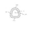
図1は、本発明の一実施形態に係る磁性体粒子操作用デバイスの構成例を示した正面図である。図2は、図1の磁性体粒子操作用デバイスのA-A断面図である。この磁性体粒子操作用デバイス1(以下、「デバイス1」という。)は、液体試料から目的物質を抽出・精製するためのものであり、一直線上に延びる管状の容器(容器本体)20を備えている。1. 1. Device for Manipulating Magnetic Particles FIG. 1 is a front view showing a configuration example of a device for manipulating magnetic particles according to an embodiment of the present invention. FIG. 2 is a cross-sectional view taken along the line AA of the device for manipulating magnetic particles of FIG. The
容器20内には、複数の液体層11と複数のゲル状媒体層12が形成されている。具体的には、容器20の最下部に液体層11が形成され、上方に向かって長手方向にゲル状媒体層12と液体層11とが交互に重層されている。この例では、4つの液体層11と3つのゲル状媒体層12が長手方向に交互に形成された構成となっているが、これに限られるものではなく、液体層11及びゲル状媒体層12の数は任意に設定可能である。 A plurality of
容器20の最上部の液体層11は、目的物質を含む液体試料であり、多数の磁性体粒子13が装填されている。容器20の最下部の液体層11は、液体試料中の目的物質を溶出させるための溶出液である。容器20の中間部の1つ又は複数(この例では2つ)の液体層11は、液体試料に含まれる夾雑物を除去するための洗浄液である。これらの各液体層11は、ゲル状媒体層12によって互いに分離されている。液体試料に含まれる目的物質は、磁性体粒子13に固定された上で、磁場を変化させることによって容器20の最上部から最下部まで移動させる操作(粒子操作)が行われ、その間に洗浄液によって洗浄された上で最下部の抽出液に抽出される。 The
磁性体粒子13は、その表面又は内部に、核酸や抗原等の目的物質を特異的に固定可能な粒子である。容器20の最上部の液体層11中で磁性体粒子13を分散させることにより、この液体層11中に含まれる目的物質が磁性体粒子13に選択的に固定される。 The
磁性体粒子13への目的物質の固定方法は特に限定されず、物理吸着、化学吸着等の各種公知の固定化メカニズムが適用可能である。例えば、ファンデルワールス力、水素結合、疎水相互作用、イオン間相互作用、π-πスタッキング等の種々の分子間力により、磁性体粒子13の表面あるいは内部に目的物質が固定される。 The method for immobilizing the target substance on the
磁性体粒子13の粒径は1mm以下が好ましく、0.1μm~500μmがより好ましく、3~5μmがさらに好ましい。磁性体粒子13の形状は、粒径が揃った球形が望ましいが、粒子操作が可能である限りにおいて、不規則な形状で、ある程度の粒径分布を持っていてもよい。磁性体粒子13の構成成分は単一物質でもよく、複数の成分からなるものでもよい。 The particle size of the
磁性体粒子13は、磁性体のみからなるものでもよいが、磁性体の表面に目的物質を特異的に固定するためのコーティングが施されたものが好ましく用いられる。磁性体としては、鉄、コバルト、ニッケル、ならびにそれらの化合物、酸化物及び合金等が挙げられる。具体的には、マグネタイト(Fe3O4)、ヘマタイト(Fe2O3又はαFe2O3)、マグヘマイト(γFe2O3)、チタノマグネタイト(xFe2TiO4・(1-x)Fe3O4)、イルメノヘマタイト(xFeTiO3・(1-x)Fe2O3)、ピロタイト(Fe1-xS(x=0~0.13)‥Fe7S8(x~0.13))、グレイガイト(Fe3S4)、ゲータイト(αFeOOH)、酸化クロム(CrO2)、パーマロイ、アルコニ磁石、ステンレス、サマリウム磁石、ネオジム磁石、バリウム磁石が挙げられる。The
磁性体粒子13に選択的に固定される目的物質としては、例えば核酸、タンパク質、糖、脂質、抗体、受容体、抗原、リガンド等の生体由来物質や細胞自身が挙げられる。目的物質が生体由来物質である場合は、分子認識等により、磁性体粒子13の内部あるいは粒子表面に目的物質が固定されてもよい。例えば、目的物質が核酸である場合は、磁性体粒子13として、表面にシリカコーティングが施された磁性体粒子等が好ましく用いられる。目的物質が、抗体(例えば、標識抗体)、受容体、抗原及びリガンド等である場合、磁性体粒子13の表面のアミノ基、カルボキシル基、エポキシ基、アピジン、ピオチン、ジゴキシゲニン、プロテインA、プロテインG等により、目的物質を粒子表面に選択的に固定できる。特定の目的物質を選択的に固定可能な磁性体粒子13として、例えば、サーモフィッシャーサイエンティフィック社 から販売されているDynabeads(登録商標)や、東洋紡績株式会社からキットとして販売されているMagextractor(商標)に含まれる磁気ビーズ 等を用いることもできる。 Examples of the target substance selectively immobilized on the
目的物質が核酸である場合、洗浄液は、核酸が磁性体粒子13の表面に固定された状態を保持したまま、液体試料中に含まれる核酸以外の成分(例えばタンパク質、糖質等)や、核酸抽出等の処理に用いられた試薬等を洗浄液中に遊離させ得るものであればよい。洗浄液としては、例えば、塩化ナトリウム、塩化カリウム、硫酸アンモニウム等の高塩濃度水溶液、エタノール、イソプロパノール等のアルコール水溶液等が挙げられる。 When the target substance is nucleic acid, the washing liquid contains components other than nucleic acid (for example, protein, sugar, etc.) and nucleic acid contained in the liquid sample while the nucleic acid remains fixed on the surface of the
核酸を溶出するための溶出液(核酸溶出液)としては、水又は低濃度の塩を含む緩衝液を用いることができる。具体的には、トリス緩衝液、リン酸緩衝液、蒸留水等を用いることができ、pH7~9に調整された5~20mMトリス緩衝液を用いることが一般的である。核酸が固定された磁性体粒子13を溶出液中で分散させることにより、核酸溶出液中に核酸を遊離溶出させることができる。回収された核酸は、必要に応じて濃縮や乾固等の操作を行った後、分析や反応等に供することができる。 As the eluate for elution of nucleic acid (nucleic acid eluate), a buffer solution containing water or a low-concentration salt can be used. Specifically, Tris buffer, phosphate buffer, distilled water and the like can be used, and it is common to use 5 to 20 mM Tris buffer adjusted to pH 7 to 9. By dispersing the
ゲル状媒体層12は、粒子操作前においてゲル状、若しくはペースト状である。ゲル状媒体層12は、隣接する液体層11に対して不溶性又は難溶性であり、化学的に不活性な物質からなることが好ましい。ここで、液体に不溶性又は難溶性であるとは、25℃における液体に対する溶解度が概ね100ppm以下であることを意味する。化学的に不活性な物質とは、液体層11との接触や磁性体粒子13の操作(すなわち、ゲル状媒体層12中で磁性体粒子13を移動させる操作)において、液体層11、磁性体粒子13や磁性体粒子13に固定された物質に、化学的な影響を及ぼさない物質を指す。 The gel-
ゲル状媒体層12の材料や組成等は、特に限定されず、物理ゲルであってもよいし、化学ゲルであってもよい。例えば、WO2012/086243号に記載されているように、非水溶性又は難水溶性の液体物質を加熱し、加熱された当該液体物質にゲル化剤を添加し、ゲル化剤を完全に溶解させた後、ゾル・ゲル転移温度以下に冷却することで、物理ゲルが形成される。 The material, composition, and the like of the gel-
容器20内への液体層11及びゲル状媒体層12の装填は、適宜の方法により行い得る。本実施形態のように管状の容器20が用いられる場合、装填に先立って容器20の一端(例えば下端)の開口が封止され、他端(例えば上端)の開口部から液体層11及びゲル状媒体層12が順次装填されることが好ましい。 The
容器20内に装填される液体層11及びゲル状媒体層12の容量は、操作対象となる磁性体粒子13の量や、操作の種類等に応じて適宜に設定され得る。本実施形態のように容器20内に複数の液体層11及びゲル状媒体層12が設けられる場合、各層の容量は同一でもよいし、異なっていてもよい。各層の厚みも適宜に設定され得る。操作性等を考慮した場合、各層の厚みは、例えば2mm~20mm程度が好ましい。 The capacities of the
容器20の最上部は、他の部分よりも内径及び外径が大きい膨出部21となっている。膨出部21の上面は開口部となっており、膨出部21に対して着脱可能なキャップ30により当該開口部を封止することができる。キャップ30を取り外した状態で、膨出部21内に液体試料が注入されることにより、容器20の最上部の液体層11が形成される。すなわち、使用前の容器20においては、膨出部21内は空の状態である。このような容器20に対して、キャップ30を取り外し、多数の磁性体粒子13が装填された液体試料を膨出部21内に注入した後、キャップ30を再度取り付けることにより、図1に示すような状態となる。 The uppermost portion of the
容器20における膨出部21よりも下方の部分は、長手方向に直交する断面形状が図2に示すような一定形状である直線部22となっている。膨出部21及び直線部22は、膨出部21側から直線部22側に向かって先細りするテーパ部23により接続されている。直線部22の下端(容器20の底面)には、開口が形成されており、当該開口がフィルム部材40により封止されている。容器20の最下部の液体層11である溶出液中に抽出された目的物質は、フィルム部材40を貫通させるようにしてピペットを溶出液中に挿入することにより、当該ピペット内に吸い出すことができる。フィルム部材40は、例えばアルミなどにより形成されるが、これに限られるものではない。 The portion of the
容器20の材料は、容器20内で磁性体粒子13を移動可能であり、液体層11及びゲル状媒体層12を保持できるものであれば、特に限定されない。容器20外から磁場を変化させる操作(磁場操作)を行うことにより容器20内の磁性体粒子13を移動させるためには、プラスチック等の透磁性材料が好ましく、例えば、ポリプロピレンやポリエチレン等のポリオレフィン、テトラフルオロエチレン等のフッ素系樹脂、ポリ塩化ビニル、ポリスチレン、ポリカーボネート、環状ポリオレフィン等の樹脂材料が挙げられる。容器20の材質としては、上述の素材の他、セラミック、ガラス、シリコーン、非磁性金属等も用いられ得る。容器20の内壁面の撥水性を高めるために、フッ素系樹脂やシリコーン等によるコーティングが行われてもよい。 The material of the
容器20の形状としては、図2に示すように、容器20における膨出部21よりも下方の直線部22の断面形状(長手方向に直交する断面形状)が、中心Cに対して非対称な形状となっている。具体的には、直線部22の正面側の外周面が平坦面221となっており、中心Cを挟んで反対側である背面側の外周面が凸湾曲面222となっている。ただし、容器20の形状は、上記のような形状に限られるものではなく、例えば直線部22の断面形状が中心Cに対して対称な形状(例えば円形など)であってもよい。また、容器20における膨出部21よりも下方の部分は、一定の断面形状を有する直線部22ではなく、断面形状が変化する段付き形状であってもよい。この場合、例えば大径部及び小径部が交互に設けられた形状であってもよい。 As for the shape of the
2.磁性体粒子操作用装置
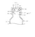
図3は、本発明の一実施形態に係る磁性体粒子操作用装置の構成例を示した正面図である。図4は、図3の磁性体粒子操作用装置のB-B断面図である。この磁性体粒子操作用装置100(以下、「装置100」という。)は、図1及び図2に示すデバイス1が固定された状態で使用され、デバイス1の容器20内の液体試料に含まれる目的物質に対して粒子操作を行うためのものである。2. 2. Magnetic Particle Manipulating Device FIG. 3 is a front view showing a configuration example of a magnetic particle manipulating device according to an embodiment of the present invention. FIG. 4 is a cross-sectional view taken along the line BB of the magnetic particle manipulation device of FIG. The magnetic particle manipulation device 100 (hereinafter referred to as “
装置100には、デバイス1を保持する容器保持部110が形成された本体101と、容器保持部110に保持されているデバイス1の容器20を押圧して固定するための容器押圧部102とを備えている。この例では、容器押圧部102が、本体101に対してヒンジ(図示せず)により回動可能に取り付けられた扉により構成されている。ただし、容器押圧部102は、容器保持部110に保持されているデバイス1を固定可能な構成であれば、本体101に対して回動可能な構成に限らず、本体101に対してスライド可能な構成や、本体101に対して着脱可能な構成などであってもよい。 The
容器保持部110は、本体101の前面120に形成された凹部により構成されている。容器保持部110は、デバイス1の容器20における膨出部21を収容する第1収容部111と、直線部22を収容する第2収容部112とが、上下方向D1に連続して延びるように形成されている。また、容器保持部110は、直線部22が延びる方向(上下方向D1)に対して直交し、本体101の前面120に平行な方向である横方向D2の幅が、デバイス1に対応する幅となっている。 The
具体的には、第1収容部111の横方向D2の幅W1は、容器20の膨出部21の幅よりも若干大きい。一方、第2収容部112の横方向D2の幅W2は、容器20の直線部22の幅よりも若干大きく、膨出部21の幅よりも小さい。また、第1収容部111及び第2収容部112は、容器20のテーパ部23に対応する角度で傾斜した絞り部113により接続されている。これにより、容器保持部110内に容器20を収容した状態では、容器20のテーパ部23が容器保持部110の絞り部113に引っ掛かり、吊り下げられた状態で保持されるようになっている。 Specifically, the width W1 of the lateral D2 of the first
図4に示すように、容器20は、平坦面221が横方向D2に延び、凸湾曲面222が平坦面221よりも背面側に位置するようにして、容器保持部110内に収容される。容器保持部110の第2収容部112の内面には、横方向D2の両側から内側に向かって突出する段差部114が形成されている。この段差部114における第1収容部111の横方向D2の幅W3は、前面120側における幅W2よりも小さく、容器20の直線部22の横方向D2の幅よりも小さい。 As shown in FIG. 4, the
したがって、前面120側から容器保持部110内に収容される容器20の直線部22は、その凸湾曲面222側が段差部114に当接した状態となる。このとき、容器20の平坦面221は、容器保持部110から本体101の前面120よりも前方に張り出した状態となる。この状態で、容器押圧部102を構成する扉を閉じることにより、図4に示すように、本体101の前面120に対向する当接面121を容器20の平坦面221に当接させ、背面側に押圧することができる。これにより、当接面121と段差部114との間で容器20の直線部22を挟み込み、直線部22を強固に固定することができる。 Therefore, the
容器保持部110の背面側は開口しており、容器保持部110に対向するように磁石130が配置されている。磁石130は、容器保持部110に保持されている容器20に対して、外側(背面側)から近接している。この磁石130は、永久磁石からなり、上下方向D1に沿ってスライド可能に保持されている。 The back side of the
磁石130は、容器20内の磁性体粒子13を磁力で引き付ける。これにより、図4に示すように凸湾曲面222側に磁性体粒子13が集められる。このようにして磁性体粒子13を磁石130側に引き付けた状態で、磁石130を上下方向D1に移動させることにより、容器20内の磁性体粒子13を上下方向D1に移動させることができる。 The
このように、磁石130は、磁場を変化させることにより容器20内の磁性体粒子13を移動させる磁場印加部を構成している。磁石130は、駆動部によりスライドさせてもよいし、手動でスライドさせてもよい。図4の例では、磁石130における容器20に対向する対向面131が、凹湾曲面により構成されている。対向面131は、容器20の凸湾曲面222に対応する曲率半径を有する凹湾曲面となっている。ただし、対向面131は、凹湾曲面により構成されるものに限らず、例えば平坦面などにより構成されていてもよい。 As described above, the
磁石130は、磁性体粒子13の操作が可能であれば、その形状や大きさ、材質は特に限定されない。磁場印加部が有する磁力源としては、永久磁石を用いる以外に電磁石を用いることも可能である。また、磁場印加部は、複数の磁力源を有してもよい。磁場印加部は、容器20に対して相対移動することにより磁場を変化させるような構成であればよく、本実施形態のように磁場印加部が移動するような構成に限らず、容器20が移動するような構成であってもよい。 The shape, size, and material of the
3.磁性体粒子の操作
図5は、磁性体粒子13を操作する際の態様について説明するための模式図である。図5では、説明を分かりやすくするために、デバイス1の形状を簡略化して示している。図5Aにおいて、容器20の最上部の液体層11には、多数の磁性体粒子13が含まれている。このように、磁性体粒子13を液体層11中で分散させることにより、液体層11中に含まれる目的物質が磁性体粒子13に選択的に固定される。3. 3. Operation of Magnetic Particles FIG. 5 is a schematic diagram for explaining an embodiment when operating
その後、図5Bに示すように、容器20の外周面に、磁力源である磁石130を近付けると、目的物質が固定された磁性体粒子13が、磁場の作用により、容器20内の磁石130側(凸湾曲面222側)に集められる。そして、図5Cに示すように、磁石130を容器20の外周面に沿って容器20の長手方向(上下方向)に移動させると、磁場の変化に追随して、磁性体粒子13も容器20の長手方向に沿って移動し、交互に重層された液体層11及びゲル状媒体層12を順次移動する。 After that, as shown in FIG. 5B, when the
磁性体粒子13の周囲に液滴として物理的に付着している液体の大半は、磁性体粒子13がゲル状媒体層12の内部に進入する際に、磁性体粒子13の表面から脱離する。ゲル状媒体層12内への磁性体粒子13の進入及び移動により、ゲル状媒体層12が穿孔されるが、ゲルの復元力による自己修復作用により、ゲル状媒体層12の孔は直ちに塞がれる。そのため、磁性体粒子13による貫通孔を介したゲル状媒体層12への液体の流入は、ほとんど生じない。 Most of the liquid physically attached as droplets around the
磁石130は、各液体層11内に対向する位置で、容器20の長手方向に沿って所定の移動ストローク及び移動速度で往復移動することにより、各液体層11内で磁性体粒子13を分散させる。液体層11内で磁性体粒子13を分散させ、磁性体粒子13を液体層11内の液体と接触させることにより、磁性体粒子13への目的物質の固定、磁性体粒子13の表面に付着している夾雑物を除去するための洗浄操作、磁性体粒子13に固定されている目的物質の反応、磁性体粒子13に固定されている目的物質の液体中への溶出等の操作が行われる。 The
4.キャップの周辺の具体的構造
図6A及び図6Bは、磁性体粒子操作用デバイス1におけるキャップ30の周辺の具体的構造を示した断面図である。図6Aでは、使用前の状態を示しており、図6Bでは、図6Aの状態からキャップ30を緩めた状態を示している。4. Specific Structure around
図6Aに示すように、容器20(膨出部21)の上端部には開口24が形成されている。容器20の上端部にキャップ30が取り付けられることにより、開口24が閉塞される。本実施形態において、キャップ30はねじ込み式であり、容器20の上端部に対して外側に被せるように螺合されることにより、容器20に取り付けられている。容器20及びキャップ30は、それぞれ例えば樹脂により形成されている。 As shown in FIG. 6A, an
キャップ30は、開口24に対向する平板部31と、それぞれ筒状に形成された外壁面32及び内壁面33とが一体的に形成された構成を有している。外壁面32及び内壁面33は、それぞれ筒状であり、平板部31における一方の面311から同一の方向(図6A及び図6Bにおける下方)に向かって突出している。 The
キャップ30の外壁面32は、開口24の内径よりも大きい内径を有する円筒状に形成されている。外壁面32の内周面にはネジ溝が形成されている。また、容器20の上端部における外周面には、キャップ30の外壁面32に形成されたネジ溝に対応するネジ山が形成されている。これにより、容器20の上端部に対して外壁面32を螺合させることができる。 The
キャップ30の内壁面33は、開口24の内径よりも小さい外径を有する円筒状に形成され、外壁面32の内側に、外壁面32と同軸上に配置されている。これにより、外壁面32と内壁面33との間には、環状の空間34が形成されている。内壁面33の高さは、外壁面32の高さよりも低い。すなわち、外壁面32の先端は、内壁面33の先端よりも下方まで突出している。図6Aのようにキャップ30が締め付けられた状態では、容器20の上端部が空間34内に進入している。 The
環状の空間34には、例えばOリングからなる環状の弾性体35が設けられている。弾性体35は、空間34の底面を構成する平板部31の一方の面311に当接している。また、環状の空間34には、攪拌子36が保持されている。攪拌子36は、容器20内の磁性体粒子13を液体層11で攪拌させるためのものである。 An annular
攪拌子36は、例えば磁性体粒子13よりも大径の球体により構成されており、その外径は1mm程度である。攪拌子36の材料は、磁性体を有する材料であれば特に限定されるものではないが、例えば鉄球の外側を樹脂でコーティングすることにより攪拌子36が形成される。攪拌子36は、環状の空間34内において、弾性体35よりも容器20側(平板部31側とは反対側)に設けられている。 The
容器20の上端部の内周面における開口24の周縁部には、テーパ面37が形成されている。テーパ面37は、容器20の内径が上端に向かって徐々に大きくなるように、すなわち開口24が徐々に拡大されるように、円錐台形状に形成されている。図6Aのようにキャップ30が締め付けられた状態では、テーパ面37と内壁面33との間に攪拌子36が挟持された状態で保持されている。このとき、弾性体35は攪拌子36に接触して弾性変形しており、その弾性力で攪拌子36がテーパ面37に密着している。 A tapered
図6Aの状態からキャップ30を緩めると、開口24に対してキャップ30の平板部31が徐々に離間し、容器20の上端部が空間34の外部(下方)に退避する。これにより、攪拌子36に対するキャップ30の内壁面33による拘束が解除され、図6Bに矢印で示すように、攪拌子36が容器20内(膨出部21内)に落下する。このとき、キャップ30は容器20から完全に脱離されておらず、容器20に対して螺合された状態のままである。この状態からさらにキャップ30を緩めれば、容器20からキャップ30を取り外し、開口24を開放することができる。 When the
このように、攪拌子36は、キャップ30が容器20に対して緩められてから脱離するまでの間に、容器20内に落下する。すなわち、使用前のデバイス1において攪拌子36を収容する空間34に保持されている攪拌子36は、容器20からキャップ30を取り外すための操作に基づいて空間34から容器20内に落下するようになっている。 In this way, the
攪拌子36が容器20内(膨出部21内)に落下した後、ユーザはさらにキャップ30を緩めて、容器20からキャップ30を取り外す。そして、多数の磁性体粒子13が装填された液体試料が開口24から膨出部21内に注入される。これにより、容器20の最上部の液体層11が形成され、当該液体層11には攪拌子36と多数の磁性体粒子13が混合された状態となる。 After the
その後、膨出部21に対向する位置で磁石130を上下方向D1に往復移動させると、膨出部21内の液体層11において攪拌子36が磁力により往復移動し、液体層11内で磁性体粒子13が攪拌される。この状態から磁石130を下方に移動させると、攪拌子36によりゲル状媒体層12が穿孔され、攪拌子36に続くようにして磁性体粒子13がゲル状媒体層12の孔内を通過した後、ゲルの復元力によりゲル状媒体層12の孔が塞がれることとなる。 After that, when the
5.作用効果
(1)本実施形態では、ゲル状媒体層12内ではなく、攪拌子36を収容する空間34に攪拌子36が保持されるため、容器20の使用前に攪拌子36を確実に保持しておくことができる。容器20の使用時には、容器20からキャップ30が取り外されて、目的物質を含む液体試料が容器20内に注入されるため、そのキャップ30を取り外す操作に基づいて攪拌子36が容器20内に落下する。これにより、キャップ30に対する操作に基づいて攪拌子36を容器20内に自動的に投入し、その後に攪拌子36を用いて磁性体粒子13を液体層11で攪拌することが可能になる。5. Action (1) In the present embodiment, the
(2)本実施形態では、キャップ30が容器20に対して緩められて脱離するまでの間に、攪拌子36が容器20内に落下するため、容器20の外側に攪拌子36が飛び出すことがない。したがって、キャップ30に対する操作に基づいて、攪拌子36を容器20内に確実に投入することができる。(2) In the present embodiment, the
(3)本実施形態では、キャップ30における外壁面32と内壁面33との間に形成された環状の空間34に攪拌子36を保持することにより、攪拌子36の移動を制限し、かつ攪拌子36を確実に保持しておくことができる。キャップ30が透明又は半透明である場合には、攪拌子36の外周面に着色を施すことにより、外部から攪拌子36を視認可能な構成としてもよい。(3) In the present embodiment, the
(4)本実施形態では、攪拌子36が、テーパ面37と内壁面33との間に挟持されている。そのため、容器20とキャップ30との間に寸法誤差がある場合であっても、テーパ面37と内壁面33との間に攪拌子36を挟持することにより、攪拌子36を確実に保持しておくことができる。(4) In the present embodiment, the
(5)本実施形態では、キャップ30を締め付けたときに、環状の弾性体35を弾性変形させることにより、その弾性力で攪拌子36を容器20(テーパ面37)に密着させることができる。これにより、攪拌子36の移動を効果的に制限し、かつ攪拌子36を確実に保持しておくことができる。(5) In the present embodiment, when the
6.変形例
図7は、磁性体粒子操作用デバイス1におけるキャップ30の周辺の具体的構造の変形例を示した断面図であり、使用前の状態を示している。この変形例では、容器20の上端部の内周面における開口24の周縁部に、テーパ面37ではなく、段差面38が形成されている。この点を除いて、他の構成は上記実施形態と同様であるため、同様の構成については、図に同一符号を付して詳細な説明を省略する。6. Modification Example FIG. 7 is a cross-sectional view showing a modification of a specific structure around the
段差面38は、容器20の上端部の内周面に対して、環状の凹部を形成することにより構成されている。図7のようにキャップ30が締め付けられた状態では、段差面38と内壁面33との間に攪拌子36が挟持された状態で保持されている。このとき、弾性体35は攪拌子36に接触して弾性変形しており、その弾性力で攪拌子36が段差面38に密着している。 The stepped
図7の状態からキャップ30を緩めると、開口24に対してキャップ30の平板部31が徐々に離間し、容器20の上端部が空間34の外部(下方)に退避する。これにより、攪拌子36に対するキャップ30の内壁面33による拘束が解除され、攪拌子36が容器20内(膨出部21内)に落下する。 When the
このように、攪拌子36が、攪拌子36を収容する空間34に保持され、容器20からキャップ30を取り外すための操作に基づいて空間34から容器20内に落下するような構成であれば、そのための構造はテーパ面37に限定されるものではなく、段差面38にも限定されない。また、空間34は、キャップ30の壁面と容器20の壁面とにより構成されていてもよい。 As described above, if the
デバイス1は、容器20とキャップ30を備えた構成であればよく、容器20やキャップ30の形状は、上記実施形態のような形状に限られるものではない。例えば、容器20は膨出部21を備えていない構成であってもよい。また、キャップ30は、ねじ込み式に限らず、嵌め込み式などの他の態様で容器20に着脱可能な構成であってもよい。 The
攪拌子36は、上記実施形態のような材質及び形状に限られるものではない。例えば、攪拌子36は、球体に限らず、矩形状などの他の形状であってもよいし、特殊な形状を有していてもよい。また、攪拌子36は、1つに限らず、複数設けられていてもよい。 The
弾性体35は、省略されてもよい。すなわち、弾性体35により攪拌子36を押圧するような構成に限らず、例えばキャップ30の平板部31(一方の面311)により攪拌子36を押圧してもよい。また、攪拌子36を容器20とキャップ30との間に固定(拘束)するような構成に限らず、攪拌子36を保持することができれば、例えば攪拌子36の上方に空間(遊び)を設けることにより、攪拌子36が移動可能な構成となっていてもよい。 The
1 磁性体粒子操作用デバイス
11 液体層
12 ゲル状媒体層
13 磁性体粒子
20 容器
21 膨出部
22 直線部
23 テーパ部
24 開口
30 キャップ
31 平板部
32 外壁面
33 内壁面
34 空間
35 弾性体
36 攪拌子
37 テーパ面
38 段差面
100 磁性体粒子操作用装置
101 本体
102 容器押圧部
110 容器保持部
130 磁石1 Device for manipulating
Claims (4)
Translated fromJapanese前記ゲル状媒体層及び前記液体層が前記長手方向に交互に重層され、一端部に開口が形成された管状の容器本体と、
前記開口の内径よりも大きい内径を有する筒状の外壁と、前記外壁よりも内側に形成された内上面と、前記開口の内径よりも小さい外径を有し、前記内上面から上下方向に延びるように前記外壁の内側に設けられ、前記外壁との間に環状の空間を形成する筒状の内壁とを有し、前記容器本体に取り付けられることにより、前記開口を閉塞するキャップと、
前記容器本体内の前記磁性体粒子を前記液体層で攪拌させるための攪拌子とを備え、
前記攪拌子は、前記環状の空間において、前記開口の周縁部と、前記内壁の外周面との間に挟持されることで保持され、前記容器本体から前記キャップを取り外すための操作に基づいて、前記攪拌子に対する前記キャップの前記内壁の外周面による拘束が解除され、前記攪拌子が前記環状の空間から前記容器本体内に落下することを特徴とする磁性体粒子操作用容器。The gel-like medium layer and the liquid layer are alternately layered in the longitudinal direction, and the target substance is fixed to the magnetic particles filled inside, and the gel-like medium layer and the liquid layer are moved by moving a magnet provided outside. A container for manipulating magnetic particles for sequentially moving the magnetic particles to the medium layer and the liquid layer.
A tubular container body in which the gel-like medium layer and the liquid layer are alternately layered in the longitudinal direction to form an opening at one end, and a tubular container body.
A cylindrical outer wall having an inner diameter larger than the inner diameter of the opening, an inner upper surface formed inside the outer wall, and an outer diameter smaller than the inner diameter of the opening, extending in the vertical direction from the inner upper surface. A capthat is provided inside the outer wall and has a tubular inner wall that forms an annular space between the outer wall and the outer wall, and is attached to the container body to close the opening.
A stirrer for stirring the magnetic particles in the container body in the liquid layer is provided.
The stirrer isheld by being sandwiched between the peripheral edge of the opening and the outer peripheral surface of the inner wall in the annular space, and is based on an operation for removing the cap from thecontainer body. A container for manipulating magnetic particles, wherein the restraint on the stirrer by the outer peripheral surface of the inner wall of the cap is released, and the stirrer falls fromthe annular space into the container body.
前記キャップが前記容器本体に対して緩められてから脱離するまでの間に、前記攪拌子が前記容器本体内に落下することを特徴とする請求項1に記載の磁性体粒子操作用容器。The inner peripheral surface of the outer wall of the cap is screwed to the container body.
The container for operating magnetic particles according to claim 1, wherein the stirrer falls into the container body between the time when the cap is loosened with respect to the container body and the time when the cap is detached from the container body.
前記攪拌子は、前記テーパ面と、前記内壁の外周面との間に挟持されていることを特徴とする請求項1又は2に記載の磁性体粒子操作用容器。A tapered surface is formed on the peripheral edge of the opening in the container body.
The container for operating magnetic particles according to claim1 or 2 , wherein the stirrer is sandwiched between the tapered surface andthe outer peripheral surface of the inner wall .
前記攪拌子は、前記弾性体よりも前記容器本体側に設けられていることを特徴とする請求項1から3のいずれか一項に記載の磁性体粒子操作用容器。Further provided with an annular elastic body provided in the annular space,
The container for manipulating magnetic particles according toany one of claims 1 to 3 , wherein the stirrer is provided on the container body side of the elastic body.
Priority Applications (1)
| Application Number | Priority Date | Filing Date | Title |
|---|---|---|---|
| JP2018128910AJP7091891B2 (en) | 2018-07-06 | 2018-07-06 | Magnetic particle manipulation container |
Applications Claiming Priority (1)
| Application Number | Priority Date | Filing Date | Title |
|---|---|---|---|
| JP2018128910AJP7091891B2 (en) | 2018-07-06 | 2018-07-06 | Magnetic particle manipulation container |
Publications (2)
| Publication Number | Publication Date |
|---|---|
| JP2020006309A JP2020006309A (en) | 2020-01-16 |
| JP7091891B2true JP7091891B2 (en) | 2022-06-28 |
Family
ID=69149831
Family Applications (1)
| Application Number | Title | Priority Date | Filing Date |
|---|---|---|---|
| JP2018128910AActiveJP7091891B2 (en) | 2018-07-06 | 2018-07-06 | Magnetic particle manipulation container |
Country Status (1)
| Country | Link |
|---|---|
| JP (1) | JP7091891B2 (en) |
Citations (9)
| Publication number | Priority date | Publication date | Assignee | Title |
|---|---|---|---|---|
| WO2012086243A1 (en) | 2010-12-21 | 2012-06-28 | 株式会社 島津製作所 | Device and method for processing target component in tube |
| CN203148829U (en) | 2013-02-01 | 2013-08-21 | 深圳市汇松科技发展有限公司 | Reagent reaction analysis device |
| JP2014176304A (en) | 2013-03-13 | 2014-09-25 | Seiko Epson Corp | Cartridge for nucleic acid amplification reaction |
| WO2015136689A1 (en) | 2014-03-14 | 2015-09-17 | 株式会社島津製作所 | Method for manipulating magnetic particles and device for manipulating magnetic particles |
| WO2015177933A1 (en) | 2014-05-23 | 2015-11-26 | 株式会社島津製作所 | Method for operating magnetic body particles and device for operating magnetic body particles |
| JP2016067274A (en) | 2014-09-30 | 2016-05-09 | セイコーエプソン株式会社 | Substance purification device and cartridge |
| JP2016117032A (en) | 2014-12-22 | 2016-06-30 | 株式会社島津製作所 | Device for operating magnetic material grains |
| JP2016535597A (en) | 2013-10-25 | 2016-11-17 | ベクトン・ディキンソン・アンド・カンパニーBecton, Dickinson And Company | Blood culture bottle with controlled release mechanism of substance into culture medium |
| JP2017127224A (en) | 2016-01-19 | 2017-07-27 | 株式会社島津製作所 | Nucleic acid pretreatment kit and nucleic acid sequence analysis method |
Family Cites Families (2)
| Publication number | Priority date | Publication date | Assignee | Title |
|---|---|---|---|---|
| WO1989005456A1 (en)* | 1987-12-01 | 1989-06-15 | Biotope, Inc. | Methods and devices for conducting assays |
| JP2014176302A (en)* | 2013-03-13 | 2014-09-25 | Seiko Epson Corp | Nucleic acid amplification reaction device and nucleic acid amplification method |
- 2018
- 2018-07-06JPJP2018128910Apatent/JP7091891B2/enactiveActive
Patent Citations (9)
| Publication number | Priority date | Publication date | Assignee | Title |
|---|---|---|---|---|
| WO2012086243A1 (en) | 2010-12-21 | 2012-06-28 | 株式会社 島津製作所 | Device and method for processing target component in tube |
| CN203148829U (en) | 2013-02-01 | 2013-08-21 | 深圳市汇松科技发展有限公司 | Reagent reaction analysis device |
| JP2014176304A (en) | 2013-03-13 | 2014-09-25 | Seiko Epson Corp | Cartridge for nucleic acid amplification reaction |
| JP2016535597A (en) | 2013-10-25 | 2016-11-17 | ベクトン・ディキンソン・アンド・カンパニーBecton, Dickinson And Company | Blood culture bottle with controlled release mechanism of substance into culture medium |
| WO2015136689A1 (en) | 2014-03-14 | 2015-09-17 | 株式会社島津製作所 | Method for manipulating magnetic particles and device for manipulating magnetic particles |
| WO2015177933A1 (en) | 2014-05-23 | 2015-11-26 | 株式会社島津製作所 | Method for operating magnetic body particles and device for operating magnetic body particles |
| JP2016067274A (en) | 2014-09-30 | 2016-05-09 | セイコーエプソン株式会社 | Substance purification device and cartridge |
| JP2016117032A (en) | 2014-12-22 | 2016-06-30 | 株式会社島津製作所 | Device for operating magnetic material grains |
| JP2017127224A (en) | 2016-01-19 | 2017-07-27 | 株式会社島津製作所 | Nucleic acid pretreatment kit and nucleic acid sequence analysis method |
Also Published As
| Publication number | Publication date |
|---|---|
| JP2020006309A (en) | 2020-01-16 |
Similar Documents
| Publication | Publication Date | Title |
|---|---|---|
| US10533170B2 (en) | Method for manipulating magnetic particles and device for manipulating magnetic particles | |
| JP6376226B2 (en) | Device for manipulating magnetic particles and method for manipulating magnetic particles | |
| JP7035316B2 (en) | Device for manipulating magnetic particles | |
| US11766672B2 (en) | Apparatus for manipulating magnetic particles | |
| JP6323550B2 (en) | Operation method of magnetic particles | |
| US11883831B2 (en) | Magnetic particle operation device | |
| JP6750692B2 (en) | Device for operating magnetic particles and apparatus for operating magnetic particles | |
| JP7091891B2 (en) | Magnetic particle manipulation container | |
| JP7110900B2 (en) | Device for Manipulating Magnetic Particles | |
| JP7139931B2 (en) | Container for Manipulating Magnetic Particles and Apparatus for Manipulating Magnetic Particles | |
| US20210222154A1 (en) | Operation method of magnetic particles | |
| CN110605181B (en) | Magnetic particle manipulation device | |
| JP2018161649A (en) | Magnetic particle operation method and magnetic particle operation device |
Legal Events
| Date | Code | Title | Description |
|---|---|---|---|
| A621 | Written request for application examination | Free format text:JAPANESE INTERMEDIATE CODE: A621 Effective date:20201201 | |
| A131 | Notification of reasons for refusal | Free format text:JAPANESE INTERMEDIATE CODE: A131 Effective date:20210831 | |
| A977 | Report on retrieval | Free format text:JAPANESE INTERMEDIATE CODE: A971007 Effective date:20210831 | |
| A601 | Written request for extension of time | Free format text:JAPANESE INTERMEDIATE CODE: A601 Effective date:20211028 | |
| A521 | Request for written amendment filed | Free format text:JAPANESE INTERMEDIATE CODE: A523 Effective date:20211214 | |
| TRDD | Decision of grant or rejection written | ||
| A01 | Written decision to grant a patent or to grant a registration (utility model) | Free format text:JAPANESE INTERMEDIATE CODE: A01 Effective date:20220517 | |
| A61 | First payment of annual fees (during grant procedure) | Free format text:JAPANESE INTERMEDIATE CODE: A61 Effective date:20220530 | |
| R151 | Written notification of patent or utility model registration | Ref document number:7091891 Country of ref document:JP Free format text:JAPANESE INTERMEDIATE CODE: R151 |