JP7090186B2 - Equipment and methods for manufacturing spacers - Google Patents
Equipment and methods for manufacturing spacersDownload PDFInfo
- Publication number
- JP7090186B2 JP7090186B2JP2021013884AJP2021013884AJP7090186B2JP 7090186 B2JP7090186 B2JP 7090186B2JP 2021013884 AJP2021013884 AJP 2021013884AJP 2021013884 AJP2021013884 AJP 2021013884AJP 7090186 B2JP7090186 B2JP 7090186B2
- Authority
- JP
- Japan
- Prior art keywords
- bone cement
- valve
- valve body
- valve seat
- casting mold
- Prior art date
- Legal status (The legal status is an assumption and is not a legal conclusion. Google has not performed a legal analysis and makes no representation as to the accuracy of the status listed.)
- Active
Links
- 125000006850spacer groupChemical group0.000titleclaimsdescription121
- 238000000034methodMethods0.000titleclaimsdescription50
- 238000004519manufacturing processMethods0.000titledescription24
- 239000002639bone cementSubstances0.000claimsdescription350
- 238000005266castingMethods0.000claimsdescription215
- 230000035515penetrationEffects0.000claimsdescription92
- 238000007789sealingMethods0.000claimsdescription48
- 229910052751metalInorganic materials0.000claimsdescription41
- 239000002184metalSubstances0.000claimsdescription41
- 239000007788liquidSubstances0.000claimsdescription22
- 239000002985plastic filmSubstances0.000claimsdescription13
- 229920006255plastic filmPolymers0.000claimsdescription13
- 239000000843powderSubstances0.000claimsdescription11
- 239000004568cementSubstances0.000claimsdescription10
- 238000000465mouldingMethods0.000claimsdescription9
- 238000002156mixingMethods0.000claimsdescription6
- 241000309551Arthraxon hispidusSpecies0.000claimsdescription5
- 238000002347injectionMethods0.000claimsdescription5
- 239000007924injectionSubstances0.000claimsdescription5
- 238000010008shearingMethods0.000claimsdescription5
- 239000000178monomerSubstances0.000claimsdescription3
- 210000001624hipAnatomy0.000description26
- 229920003229poly(methyl methacrylate)Polymers0.000description23
- 239000004926polymethyl methacrylateSubstances0.000description23
- 230000000149penetrating effectEffects0.000description15
- 208000015943Coeliac diseaseDiseases0.000description12
- 210000000323shoulder jointAnatomy0.000description9
- 230000003115biocidal effectEffects0.000description8
- 244000005700microbiomeSpecies0.000description8
- 239000003242anti bacterial agentSubstances0.000description7
- 210000000988bone and boneAnatomy0.000description7
- 239000012530fluidSubstances0.000description7
- 210000004394hip jointAnatomy0.000description7
- 208000015181infectious diseaseDiseases0.000description6
- 229920003023plasticPolymers0.000description6
- 239000004033plasticSubstances0.000description6
- 239000004480active ingredientSubstances0.000description4
- 229940088710antibiotic agentDrugs0.000description4
- 239000000463materialSubstances0.000description4
- 239000004698PolyethyleneSubstances0.000description3
- 229940121375antifungal agentDrugs0.000description3
- 238000001804debridementMethods0.000description3
- 238000001746injection mouldingMethods0.000description3
- 229920000573polyethylenePolymers0.000description3
- 229920005644polyethylene terephthalate glycol copolymerPolymers0.000description3
- 230000006641stabilisationEffects0.000description3
- 238000011105stabilizationMethods0.000description3
- 229910000811surgical stainless steelInorganic materials0.000description3
- 238000003466weldingMethods0.000description3
- 239000004952PolyamideSubstances0.000description2
- 241000191967Staphylococcus aureusSpecies0.000description2
- 241000191963Staphylococcus epidermidisSpecies0.000description2
- RTAQQCXQSZGOHL-UHFFFAOYSA-NTitaniumChemical compound[Ti]RTAQQCXQSZGOHL-UHFFFAOYSA-N0.000description2
- 239000003429antifungal agentSubstances0.000description2
- 230000015572biosynthetic processEffects0.000description2
- 230000006837decompressionEffects0.000description2
- 238000007599dischargingMethods0.000description2
- 235000012907honeyNutrition0.000description2
- 238000002513implantationMethods0.000description2
- 238000003780insertionMethods0.000description2
- 230000037431insertionEffects0.000description2
- 230000002262irrigationEffects0.000description2
- 238000003973irrigationMethods0.000description2
- 239000000203mixtureSubstances0.000description2
- 229920002647polyamidePolymers0.000description2
- -1polyethylene terephthalatePolymers0.000description2
- 229920000139polyethylene terephthalatePolymers0.000description2
- 239000005020polyethylene terephthalateSubstances0.000description2
- 230000002787reinforcementEffects0.000description2
- 239000000126substanceSubstances0.000description2
- 239000010936titaniumSubstances0.000description2
- 229910052719titaniumInorganic materials0.000description2
- 210000000689upper legAnatomy0.000description2
- 241000894006BacteriaSpecies0.000description1
- 241000233866FungiSpecies0.000description1
- 206010061218InflammationDiseases0.000description1
- 240000004808Saccharomyces cerevisiaeSpecies0.000description1
- 206010048629Wound secretionDiseases0.000description1
- 239000013543active substanceSubstances0.000description1
- 230000006978adaptationEffects0.000description1
- 238000004026adhesive bondingMethods0.000description1
- 230000000843anti-fungal effectEffects0.000description1
- 235000013405beerNutrition0.000description1
- 230000017531blood circulationEffects0.000description1
- 210000001124body fluidAnatomy0.000description1
- 239000010839body fluidSubstances0.000description1
- 238000005336crackingMethods0.000description1
- 238000005520cutting processMethods0.000description1
- 230000007547defectEffects0.000description1
- 238000010586diagramMethods0.000description1
- 230000000694effectsEffects0.000description1
- 239000007943implantSubstances0.000description1
- 230000002757inflammatory effectEffects0.000description1
- 230000004054inflammatory processEffects0.000description1
- 238000005304joiningMethods0.000description1
- 239000003550markerSubstances0.000description1
- 229910001092metal group alloyInorganic materials0.000description1
- 239000002245particleSubstances0.000description1
- 238000006116polymerization reactionMethods0.000description1
- 230000003362replicative effectEffects0.000description1
- 239000011347resinSubstances0.000description1
- 229920005989resinPolymers0.000description1
- 230000002441reversible effectEffects0.000description1
- 210000004872soft tissueAnatomy0.000description1
- 238000001356surgical procedureMethods0.000description1
- 238000003856thermoformingMethods0.000description1
- 229920001169thermoplasticPolymers0.000description1
- 239000004416thermosoftening plasticSubstances0.000description1
- XLYOFNOQVPJJNP-UHFFFAOYSA-NwaterSubstancesOXLYOFNOQVPJJNP-UHFFFAOYSA-N0.000description1
Images


Classifications
- A—HUMAN NECESSITIES
- A61—MEDICAL OR VETERINARY SCIENCE; HYGIENE
- A61F—FILTERS IMPLANTABLE INTO BLOOD VESSELS; PROSTHESES; DEVICES PROVIDING PATENCY TO, OR PREVENTING COLLAPSING OF, TUBULAR STRUCTURES OF THE BODY, e.g. STENTS; ORTHOPAEDIC, NURSING OR CONTRACEPTIVE DEVICES; FOMENTATION; TREATMENT OR PROTECTION OF EYES OR EARS; BANDAGES, DRESSINGS OR ABSORBENT PADS; FIRST-AID KITS
- A61F2/00—Filters implantable into blood vessels; Prostheses, i.e. artificial substitutes or replacements for parts of the body; Appliances for connecting them with the body; Devices providing patency to, or preventing collapsing of, tubular structures of the body, e.g. stents
- A61F2/02—Prostheses implantable into the body
- A61F2/30—Joints
- A61F2/3094—Designing or manufacturing processes
- A61F2/30942—Designing or manufacturing processes for designing or making customized prostheses, e.g. using templates, CT or NMR scans, finite-element analysis or CAD-CAM techniques
- A—HUMAN NECESSITIES
- A61—MEDICAL OR VETERINARY SCIENCE; HYGIENE
- A61F—FILTERS IMPLANTABLE INTO BLOOD VESSELS; PROSTHESES; DEVICES PROVIDING PATENCY TO, OR PREVENTING COLLAPSING OF, TUBULAR STRUCTURES OF THE BODY, e.g. STENTS; ORTHOPAEDIC, NURSING OR CONTRACEPTIVE DEVICES; FOMENTATION; TREATMENT OR PROTECTION OF EYES OR EARS; BANDAGES, DRESSINGS OR ABSORBENT PADS; FIRST-AID KITS
- A61F2/00—Filters implantable into blood vessels; Prostheses, i.e. artificial substitutes or replacements for parts of the body; Appliances for connecting them with the body; Devices providing patency to, or preventing collapsing of, tubular structures of the body, e.g. stents
- A61F2/02—Prostheses implantable into the body
- A61F2/30—Joints
- A61F2/46—Special tools for implanting artificial joints
- A61F2/4684—Trial or dummy prostheses
- A—HUMAN NECESSITIES
- A61—MEDICAL OR VETERINARY SCIENCE; HYGIENE
- A61F—FILTERS IMPLANTABLE INTO BLOOD VESSELS; PROSTHESES; DEVICES PROVIDING PATENCY TO, OR PREVENTING COLLAPSING OF, TUBULAR STRUCTURES OF THE BODY, e.g. STENTS; ORTHOPAEDIC, NURSING OR CONTRACEPTIVE DEVICES; FOMENTATION; TREATMENT OR PROTECTION OF EYES OR EARS; BANDAGES, DRESSINGS OR ABSORBENT PADS; FIRST-AID KITS
- A61F2/00—Filters implantable into blood vessels; Prostheses, i.e. artificial substitutes or replacements for parts of the body; Appliances for connecting them with the body; Devices providing patency to, or preventing collapsing of, tubular structures of the body, e.g. stents
- A61F2/02—Prostheses implantable into the body
- A61F2/30—Joints
- A61F2/30721—Accessories
- A61F2/30724—Spacers for centering an implant in a bone cavity, e.g. in a cement-receiving cavity
- A—HUMAN NECESSITIES
- A61—MEDICAL OR VETERINARY SCIENCE; HYGIENE
- A61F—FILTERS IMPLANTABLE INTO BLOOD VESSELS; PROSTHESES; DEVICES PROVIDING PATENCY TO, OR PREVENTING COLLAPSING OF, TUBULAR STRUCTURES OF THE BODY, e.g. STENTS; ORTHOPAEDIC, NURSING OR CONTRACEPTIVE DEVICES; FOMENTATION; TREATMENT OR PROTECTION OF EYES OR EARS; BANDAGES, DRESSINGS OR ABSORBENT PADS; FIRST-AID KITS
- A61F2/00—Filters implantable into blood vessels; Prostheses, i.e. artificial substitutes or replacements for parts of the body; Appliances for connecting them with the body; Devices providing patency to, or preventing collapsing of, tubular structures of the body, e.g. stents
- A61F2/02—Prostheses implantable into the body
- A61F2/30—Joints
- A61F2/32—Joints for the hip
- A61F2/36—Femoral heads ; Femoral endoprostheses
- A61F2/3609—Femoral heads or necks; Connections of endoprosthetic heads or necks to endoprosthetic femoral shafts
- A—HUMAN NECESSITIES
- A61—MEDICAL OR VETERINARY SCIENCE; HYGIENE
- A61F—FILTERS IMPLANTABLE INTO BLOOD VESSELS; PROSTHESES; DEVICES PROVIDING PATENCY TO, OR PREVENTING COLLAPSING OF, TUBULAR STRUCTURES OF THE BODY, e.g. STENTS; ORTHOPAEDIC, NURSING OR CONTRACEPTIVE DEVICES; FOMENTATION; TREATMENT OR PROTECTION OF EYES OR EARS; BANDAGES, DRESSINGS OR ABSORBENT PADS; FIRST-AID KITS
- A61F2/00—Filters implantable into blood vessels; Prostheses, i.e. artificial substitutes or replacements for parts of the body; Appliances for connecting them with the body; Devices providing patency to, or preventing collapsing of, tubular structures of the body, e.g. stents
- A61F2/02—Prostheses implantable into the body
- A61F2/30—Joints
- A61F2/32—Joints for the hip
- A61F2/36—Femoral heads ; Femoral endoprostheses
- A61F2/3662—Femoral shafts
- A—HUMAN NECESSITIES
- A61—MEDICAL OR VETERINARY SCIENCE; HYGIENE
- A61F—FILTERS IMPLANTABLE INTO BLOOD VESSELS; PROSTHESES; DEVICES PROVIDING PATENCY TO, OR PREVENTING COLLAPSING OF, TUBULAR STRUCTURES OF THE BODY, e.g. STENTS; ORTHOPAEDIC, NURSING OR CONTRACEPTIVE DEVICES; FOMENTATION; TREATMENT OR PROTECTION OF EYES OR EARS; BANDAGES, DRESSINGS OR ABSORBENT PADS; FIRST-AID KITS
- A61F2/00—Filters implantable into blood vessels; Prostheses, i.e. artificial substitutes or replacements for parts of the body; Appliances for connecting them with the body; Devices providing patency to, or preventing collapsing of, tubular structures of the body, e.g. stents
- A61F2/02—Prostheses implantable into the body
- A61F2/30—Joints
- A61F2/40—Joints for shoulders
- A61F2/4014—Humeral heads or necks; Connections of endoprosthetic heads or necks to endoprosthetic humeral shafts
- A—HUMAN NECESSITIES
- A61—MEDICAL OR VETERINARY SCIENCE; HYGIENE
- A61F—FILTERS IMPLANTABLE INTO BLOOD VESSELS; PROSTHESES; DEVICES PROVIDING PATENCY TO, OR PREVENTING COLLAPSING OF, TUBULAR STRUCTURES OF THE BODY, e.g. STENTS; ORTHOPAEDIC, NURSING OR CONTRACEPTIVE DEVICES; FOMENTATION; TREATMENT OR PROTECTION OF EYES OR EARS; BANDAGES, DRESSINGS OR ABSORBENT PADS; FIRST-AID KITS
- A61F2/00—Filters implantable into blood vessels; Prostheses, i.e. artificial substitutes or replacements for parts of the body; Appliances for connecting them with the body; Devices providing patency to, or preventing collapsing of, tubular structures of the body, e.g. stents
- A61F2/02—Prostheses implantable into the body
- A61F2/30—Joints
- A61F2/40—Joints for shoulders
- A61F2/4059—Humeral shafts
- B—PERFORMING OPERATIONS; TRANSPORTING
- B29—WORKING OF PLASTICS; WORKING OF SUBSTANCES IN A PLASTIC STATE IN GENERAL
- B29C—SHAPING OR JOINING OF PLASTICS; SHAPING OF MATERIAL IN A PLASTIC STATE, NOT OTHERWISE PROVIDED FOR; AFTER-TREATMENT OF THE SHAPED PRODUCTS, e.g. REPAIRING
- B29C45/00—Injection moulding, i.e. forcing the required volume of moulding material through a nozzle into a closed mould; Apparatus therefor
- B29C45/17—Component parts, details or accessories; Auxiliary operations
- B29C45/26—Moulds
- B29C45/34—Moulds having venting means
- A—HUMAN NECESSITIES
- A61—MEDICAL OR VETERINARY SCIENCE; HYGIENE
- A61F—FILTERS IMPLANTABLE INTO BLOOD VESSELS; PROSTHESES; DEVICES PROVIDING PATENCY TO, OR PREVENTING COLLAPSING OF, TUBULAR STRUCTURES OF THE BODY, e.g. STENTS; ORTHOPAEDIC, NURSING OR CONTRACEPTIVE DEVICES; FOMENTATION; TREATMENT OR PROTECTION OF EYES OR EARS; BANDAGES, DRESSINGS OR ABSORBENT PADS; FIRST-AID KITS
- A61F2/00—Filters implantable into blood vessels; Prostheses, i.e. artificial substitutes or replacements for parts of the body; Appliances for connecting them with the body; Devices providing patency to, or preventing collapsing of, tubular structures of the body, e.g. stents
- A61F2/02—Prostheses implantable into the body
- A61F2/30—Joints
- A61F2002/30001—Additional features of subject-matter classified in A61F2/28, A61F2/30 and subgroups thereof
- A61F2002/30667—Features concerning an interaction with the environment or a particular use of the prosthesis
- A61F2002/30672—Features concerning an interaction with the environment or a particular use of the prosthesis temporary
- A—HUMAN NECESSITIES
- A61—MEDICAL OR VETERINARY SCIENCE; HYGIENE
- A61F—FILTERS IMPLANTABLE INTO BLOOD VESSELS; PROSTHESES; DEVICES PROVIDING PATENCY TO, OR PREVENTING COLLAPSING OF, TUBULAR STRUCTURES OF THE BODY, e.g. STENTS; ORTHOPAEDIC, NURSING OR CONTRACEPTIVE DEVICES; FOMENTATION; TREATMENT OR PROTECTION OF EYES OR EARS; BANDAGES, DRESSINGS OR ABSORBENT PADS; FIRST-AID KITS
- A61F2/00—Filters implantable into blood vessels; Prostheses, i.e. artificial substitutes or replacements for parts of the body; Appliances for connecting them with the body; Devices providing patency to, or preventing collapsing of, tubular structures of the body, e.g. stents
- A61F2/02—Prostheses implantable into the body
- A61F2/30—Joints
- A61F2002/30001—Additional features of subject-matter classified in A61F2/28, A61F2/30 and subgroups thereof
- A61F2002/30667—Features concerning an interaction with the environment or a particular use of the prosthesis
- A61F2002/30677—Means for introducing or releasing pharmaceutical products, e.g. antibiotics, into the body
- A—HUMAN NECESSITIES
- A61—MEDICAL OR VETERINARY SCIENCE; HYGIENE
- A61F—FILTERS IMPLANTABLE INTO BLOOD VESSELS; PROSTHESES; DEVICES PROVIDING PATENCY TO, OR PREVENTING COLLAPSING OF, TUBULAR STRUCTURES OF THE BODY, e.g. STENTS; ORTHOPAEDIC, NURSING OR CONTRACEPTIVE DEVICES; FOMENTATION; TREATMENT OR PROTECTION OF EYES OR EARS; BANDAGES, DRESSINGS OR ABSORBENT PADS; FIRST-AID KITS
- A61F2/00—Filters implantable into blood vessels; Prostheses, i.e. artificial substitutes or replacements for parts of the body; Appliances for connecting them with the body; Devices providing patency to, or preventing collapsing of, tubular structures of the body, e.g. stents
- A61F2/02—Prostheses implantable into the body
- A61F2/30—Joints
- A61F2/3094—Designing or manufacturing processes
- A61F2/30942—Designing or manufacturing processes for designing or making customized prostheses, e.g. using templates, CT or NMR scans, finite-element analysis or CAD-CAM techniques
- A61F2002/30957—Designing or manufacturing processes for designing or making customized prostheses, e.g. using templates, CT or NMR scans, finite-element analysis or CAD-CAM techniques using a positive or a negative model, e.g. moulds
- A—HUMAN NECESSITIES
- A61—MEDICAL OR VETERINARY SCIENCE; HYGIENE
- A61F—FILTERS IMPLANTABLE INTO BLOOD VESSELS; PROSTHESES; DEVICES PROVIDING PATENCY TO, OR PREVENTING COLLAPSING OF, TUBULAR STRUCTURES OF THE BODY, e.g. STENTS; ORTHOPAEDIC, NURSING OR CONTRACEPTIVE DEVICES; FOMENTATION; TREATMENT OR PROTECTION OF EYES OR EARS; BANDAGES, DRESSINGS OR ABSORBENT PADS; FIRST-AID KITS
- A61F2310/00—Prostheses classified in A61F2/28 or A61F2/30 - A61F2/44 being constructed from or coated with a particular material
- A61F2310/00005—The prosthesis being constructed from a particular material
- A61F2310/00353—Bone cement, e.g. polymethylmethacrylate or PMMA
- B—PERFORMING OPERATIONS; TRANSPORTING
- B29—WORKING OF PLASTICS; WORKING OF SUBSTANCES IN A PLASTIC STATE IN GENERAL
- B29C—SHAPING OR JOINING OF PLASTICS; SHAPING OF MATERIAL IN A PLASTIC STATE, NOT OTHERWISE PROVIDED FOR; AFTER-TREATMENT OF THE SHAPED PRODUCTS, e.g. REPAIRING
- B29C45/00—Injection moulding, i.e. forcing the required volume of moulding material through a nozzle into a closed mould; Apparatus therefor
- B29C45/0001—Injection moulding, i.e. forcing the required volume of moulding material through a nozzle into a closed mould; Apparatus therefor characterised by the choice of material
- B—PERFORMING OPERATIONS; TRANSPORTING
- B29—WORKING OF PLASTICS; WORKING OF SUBSTANCES IN A PLASTIC STATE IN GENERAL
- B29K—INDEXING SCHEME ASSOCIATED WITH SUBCLASSES B29B, B29C OR B29D, RELATING TO MOULDING MATERIALS OR TO MATERIALS FOR MOULDS, REINFORCEMENTS, FILLERS OR PREFORMED PARTS, e.g. INSERTS
- B29K2033/00—Use of polymers of unsaturated acids or derivatives thereof as moulding material
- B29K2033/04—Polymers of esters
- B29K2033/12—Polymers of methacrylic acid esters, e.g. PMMA, i.e. polymethylmethacrylate
Landscapes
- Health & Medical Sciences (AREA)
- Orthopedic Medicine & Surgery (AREA)
- Engineering & Computer Science (AREA)
- Transplantation (AREA)
- Animal Behavior & Ethology (AREA)
- Veterinary Medicine (AREA)
- Biomedical Technology (AREA)
- Heart & Thoracic Surgery (AREA)
- Vascular Medicine (AREA)
- Life Sciences & Earth Sciences (AREA)
- Cardiology (AREA)
- General Health & Medical Sciences (AREA)
- Public Health (AREA)
- Oral & Maxillofacial Surgery (AREA)
- Manufacturing & Machinery (AREA)
- Physics & Mathematics (AREA)
- Geometry (AREA)
- Mechanical Engineering (AREA)
- Physical Education & Sports Medicine (AREA)
- Prostheses (AREA)
- Sliding Valves (AREA)
- Surgical Instruments (AREA)
- Materials For Medical Uses (AREA)
Description
Translated fromJapanese本発明は、骨セメントペーストを硬化させることによりスペーサを製造するための装置に関する。このスペーサは、関節の関節面を含む関節又は関節の一部を一時的に置換するための医療用途における一時的な代替物として提供される。好ましくは、このスペーサは、股関節又は肩関節を一時的に置換するために好適であり、そのために提供される。従って、当該装置は、好ましくは、股関節スペーサ又は肩関節スペーサを製造するために提供される。本発明は、このような装置を用いてこのようなスペーサを製造するための方法にも関する。 The present invention relates to an apparatus for producing a spacer by curing a bone cement paste. This spacer is provided as a temporary replacement in medical applications for the temporary replacement of a joint or part of a joint, including the articular surface of the joint. Preferably, the spacer is suitable for and is provided for the temporary replacement of the hip or shoulder joint. Therefore, the device is preferably provided for manufacturing hip or shoulder spacers. The present invention also relates to a method for manufacturing such a spacer using such a device.
股関節エンドプロテーゼや肩関節エンドプロテーゼ等の関節エンドプロテーゼは、世界中で広く埋め込まれている。残念なことに、ごく一部の症例では、関節エンドプロテーゼは、微生物、特にグラム陽性細菌及びグラム陰性細菌、さらにはごくわずかな程度では酵母及び真菌によってコロニー形成される。これらの微生物は、主に黄色ブドウ球菌(スタフィロコックス・アウレウス、Staphylococcus aureus)や表皮ブドウ球菌(スタフィロコッカス・エピデルミデス、Staphylococcus epidermidis)等の代表的な皮膚微生物は、外科手術(OP)中に患者の体内に侵入することがある。微生物が関節エンドプロテーゼに血行により侵入することもある。関節エンドプロテーゼが微生物によってコロニー形成されると、周囲の骨及び軟部組織もまた微生物によって感染し、損傷を受ける。 Joint end prostheses such as hip end prostheses and shoulder end prostheses are widely implanted worldwide. Unfortunately, in very few cases, joint endoprostheses are colonized by microorganisms, especially Gram-positive and Gram-negative bacteria, and to a small extent yeast and fungi. These microorganisms are mainly staphylococcus aureus (Staphylococcus aureus) and Staphylococcus epidermidis (Staphylococcus epidermidis), which are typical skin microorganisms during surgery (OP). May invade the patient's body. Microorganisms can also invade the joint endoprosthesis by blood circulation. When the joint endoprosthesis is colonized by microorganisms, the surrounding bone and soft tissues are also infected and damaged by the microorganisms.
先行技術は、主に、感染した関節エンドプロテーゼに対する2つの処置方法、一期的感染部位再置換及び二期的感染部位再置換を包含している。一期的再置換の場合、まず感染した関節エンドプロテーゼは取り除かれ、次に根治的なデブリードマンが行われ、次いで一回のOP内で再置換関節エンドプロテーゼが埋め込まれる。 Prior art primarily involves two treatment methods for infected joint end prostheses, one-stage infection site revision and two-stage infection site revision. In the case of one-stage revisions, the infected joint end prosthesis is first removed, then a radical debridement is performed, and then the revision joint end prosthesis is implanted within a single OP.
二期的感染部位再置換では、最初のOPで、感染した関節エンドプロテーゼが最初に取り除かれ、次にデブリードマンが行われ、その後スペーサが埋め込まれる。股関節スペーサは、ステム、カラー、ネック、ボールヘッドで構成されており、股関節エンドプロテーゼの形状とサイズを複製している。同様に、肩関節スペーサは、肩関節エンドプロテーゼの形状とサイズを複製している。スペーサは、骨セメントでそれぞれの骨に固定され、すなわち、例えば、股関節スペーサの場合、大腿骨近位部や大腿管に固定される。スペーサは、炎症がおさまって臨床的な炎症マーカーが後退するまで、患者の体内に数週間まで留置される。その後、2回目のOPでこのスペーサが取り除かれ、新たなデブリードマンの後に再置換関節エンドプロテーゼが埋め込まれる。 In a two-stage infection site revision, in the first OP, the infected joint end prosthesis is first removed, then a debridement is performed, and then a spacer is implanted. The hip spacer consists of a stem, collar, neck and ball head, replicating the shape and size of the hip end prosthesis. Similarly, the shoulder spacer replicates the shape and size of the shoulder end prosthesis. The spacers are secured to each bone with bone cement, i.e., for example, in the case of hip spacers, to the proximal femur or the femoral canal. The spacer is indwelled in the patient for up to several weeks until the inflammation subsides and the clinical inflammatory marker recedes. The spacer is then removed in the second OP and a revision joint end prosthesis is implanted after a new debridement.
スペーサに関しては、実際にスペーサを製造する前に、抗生物質がセメント粉末に添加される。この抗生物質で変性された骨セメント粉末を使用して、次にモノマー液体を混合して骨セメントペーストが製造され、この骨セメントペーストからスペーサが成型され、このスペーサは、次いでセメント粉末に添加されたモノマー液体を用いた重合により硬化される。このようにして、骨セメントペーストは抗生物質を実質的に包み込む。表面に近い領域に位置する抗生物質粒子は、創傷分泌物等の体液の作用下で放出される。活性成分の放出は開始時に最大で、その後数日の間に減少する。 For spacers, antibiotics are added to the cement powder prior to the actual production of the spacer. The bone cement powder modified with this antibiotic is then mixed with a monomeric liquid to produce a bone cement paste, from which a spacer is molded, which spacer is then added to the cement powder. It is cured by polymerization using a cement liquid. In this way, the bone cement paste substantially envelops the antibiotic. Antibiotic particles located in areas close to the surface are released under the action of body fluids such as wound secretions. The release of the active ingredient is maximal at the start and then diminishes over the next few days.
米国特許出願公開第2010/0042213A1号明細書は、インプラント内に液体のためのリザーバを有する股関節プロテーゼを開示している。凹部を有する股関節スペーサは、国際公開第2017/178951A1号パンフレットから公知であり、この股関節スペーサでは、骨を処置するための物質がこの凹部内に導入されてもよい。米国特許第6245111B1号明細書は、抗生物質で表面が被覆された股関節プロテーゼを提案している。米国特許第5681289号明細書は、装置内の液袋を活用して液体活性成分を分配するための装置を開示している。記載されたいずれのプロテーゼも、灌注回路を製造するのに適していない。欧州特許第1 991 170B1号明細書及び米国特許出願公開第2011/0015754A1号明細書は、活性成分を含む股関節スペーサを記載している。米国特許出願公開第2019/0290833A1号明細書は、液体回路が作製可能な灌注可能な股関節スペーサを開示する。国際公開第2016/205077A1号パンフレット及び米国特許第8900322B2号明細書は、灌注機能を有するスペーサをさらに記載している。 US Patent Application Publication No. 2010/0042213A1 discloses a hip prosthesis with a reservoir for fluid within the implant. A hip spacer having a recess is known from International Publication No. 2017/178951A1 pamphlet, in which a substance for treating bone may be introduced into the recess. US Pat. No. 6,245,111B1 proposes a hip prosthesis whose surface is coated with an antibiotic. US Pat. No. 5,681,289 discloses an apparatus for distributing a liquid active ingredient by utilizing a liquid bag in the apparatus. None of the prostheses described are suitable for making irrigation circuits. European Patent No. 1991 170B1 and US Patent Application Publication No. 2011/0015754A1 describe hip spacers containing the active ingredient. US Patent Application Publication No. 2019/0290833A1 discloses an injectable hip spacer in which a liquid circuit can be made. WO 2016/205077A1 and US Pat. No. 8900322B2 further describe spacers with irrigation function.
抗生物質を備えたスペーサを使用することは公知である。スペーサは、一方では、例えば特許独国特許第10 2015 104 704B4号明細書又は欧州特許第2 617 393B1号明細書に記載されているように、PMMA骨セメント粉末、抗生物質及びモノマー液体から、OP自体の間にOP担当者によって、例えばスペーサ型を用いて製造されてもよい。他方で、骨セメントから工業的に既製の股関節スペーサを使用することも従来から行われている。一部構成の(一体型)股関節スペーサの術中製造のための樹脂注型型は、米国特許第6361731B1号明細書に記載されている。これらの注型型は透明であり、2つの別個の充填開口部を有する。その結果、骨セメントペーストのための流路が比較的短いため、高粘度の骨セメントペーストであっても、ほとんど圧力をかけずに注型型内に導入することができる。高粘度でない骨セメントペーストを使用する場合には、注型型への充填が完了すると、硬化が始まる前に骨セメントペーストが充填開口部から逆流してしまう危険性がある。 It is known to use spacers with antibiotics. Spacers, on the one hand, are OP from PMMA bone cement powders, antibiotics and monomeric liquids, as described, for example, in Patent German Patent No. 10 2015 104 704B4 or European Patent No. 2 617 393B1. It may be manufactured by an OP person in between itself, for example using a spacer type. On the other hand, industrially off-the-shelf hip joint spacers from bone cement have also been conventionally used. A resin cast for the intraoperative manufacture of a partially configured (integrated) hip spacer is described in US Pat. No. 6,361,731B1. These casts are transparent and have two separate filling openings. As a result, since the flow path for the bone cement paste is relatively short, even a highly viscous bone cement paste can be introduced into the casting mold with almost no pressure applied. When using non-viscous bone cement paste, there is a risk that the bone cement paste will flow back through the filling opening before filling into the casting mold is complete.
さらなる展開として、特許明細書米国特許第7637729B2号明細書、米国特許第7789646B2号明細書、米国特許第8480389B2号明細書及び米国特許第8801983B2号明細書では、モジュール式股関節スペーサを製造するための多部構成の注型型が提案されている。これらのモジュール式股関節スペーサは、スペーサヘッドと別個のステムから構成されている。それゆえ、スペーサヘッドには1つの注型型が必要であり、ステムには別の注型型が必要となる。ステム用の注型型は一部構成であり、その注型型を骨セメントペーストを含むセメントカートリッジに接続するための充填開口部にねじ部を有する。 As a further development, US Pat. No. 7,637,729B2, US Pat. No. 7,789,646B2, US Pat. No. 8,480,389B2 and US Pat. No. 8,801,83B2 are used to manufacture modular hip spacers. A casting type of component composition has been proposed. These modular hip spacers consist of a spacer head and a separate stem. Therefore, the spacer head requires one casting and the stem requires another casting. The casting mold for the stem is a partial configuration and has a threaded portion in the filling opening for connecting the casting mold to a cement cartridge containing bone cement paste.
米国特許出願公開第2007/0222114A1号明細書には、股関節用スペーサ用の型が記載されている。このスペーサ型は、互いに接続された複数の型セグメントからなる。この複数のセグメントによって、このスペーサ型は、患者の解剖学的状況に非常に正確に適合させることができる。スペーサ型のセグメントは、ウォームドライブホースクリップによって一緒に結合されている。PMMA骨セメントペースト(ポリメタクリル酸メチル骨セメントペースト)は、スペーサ型のチャンネルを通して導入される。この注型型の複雑な構造のため、スペーサ型セグメントを一緒に結合すること、及びPMMA骨セメントペーストの硬化が完了した後に股関節スペーサを取り出すことが非常に複雑になっている。 US Patent Application Publication No. 2007/02222114A1 describes a type for a hip spacer. This spacer type consists of a plurality of type segments connected to each other. This multiple segment allows the spacer type to be very accurately adapted to the patient's anatomical situation. The spacer-shaped segments are joined together by a worm drive hose clip. PMMA bone cement paste (polymethylmethacrylate bone cement paste) is introduced through spacer-type channels. The complex structure of this casting makes it very complicated to join the spacer-type segments together and to remove the hip spacer after the PMMA bone cement paste has been cured.
国際公開第2009/073781A2号パンフレットは、ステムの長さの適応を可能にするために、互いに相対的に変位しうる2つの部分からなる股関節スペーサのためのスペーサ型を提案している。欧州特許出願公開第2 522 310A1号明細書には、さらなる注型型が開示されている。この装置は、少なくとも2つの部分からなり、第1の部分には挿入部が配置され、第2の部分には挿入受けが配置されている。この2つの部分は、互いに嵌め込まれて、股関節スペーサのステムを製造するための注型型を形成することができる。欧州特許出願公開第2 787 928A1号明細書には、複雑な注型型が記載されている。この注型型により、異なるボールヘッドを有する股関節スペーサを製造することができる。この注型型の要素は、接続要素を用いて所定の位置に固定される。米国特許第7789646B2号明細書は、骨セメントペーストが注型型内に導入されると、プラグを用いて注型型の充填開口部を閉じることができる注型型を記載している。しかしながら、その前に、この注型型は、骨セメントカートリッジから螺合解除しなければならない。それゆえ、高粘度でない骨セメントペーストを使用する場合には、注型型の持ち方が悪いと、プラグを螺合したり入れたりする前に注型型と骨セメントカートリッジを分離する際に、骨セメントペーストが流出してしまう可能性がある。 WO 2009/073781A2 proposes a spacer type for a hip spacer consisting of two parts that can be displaced relative to each other to allow adaptation of stem length. A further cast type is disclosed in Publication No. 2522 310A1 of the European Patent Application. This device consists of at least two parts, the first part having an insertion portion and the second part having an insertion receiver. The two parts can be fitted together to form a cast for making a stem for a hip spacer. European Patent Application Publication No. 2 787 928A1 describes a complex cast type. This casting allows the production of hip spacers with different ball heads. This cast element is fixed in place using a connecting element. US Pat. No. 7,789,646B2 describes a casting mold in which the filling opening of the casting mold can be closed with a plug when the bone cement paste is introduced into the casting mold. However, prior to that, the casting must be unscrewed from the bone cement cartridge. Therefore, when using non-viscous bone cement paste, poor holding of the casting mold will result in separating the casting mold from the bone cement cartridge before screwing or inserting the plug. Bone cement paste may flow out.
従って、本発明の目的は、先行技術の欠点を克服することにある。特に、本発明の目的は、骨セメントペーストを硬化させることによりスペーサを製造するための安価な装置の開発と、骨セメントペーストを硬化させることによりスペーサを製造するための安価な装置の開発と、骨セメントペースト、特にポリメタクリル酸メチル骨セメントを使用して手術室の医療従事者によって一部構成のスペーサ、特に股関節スペーサ及び肩関節スペーサを製造することができる、骨セメントペーストを硬化させることによりスペーサを製造するために、簡単にかつ安価に実施することができる方法の開発とにある。股関節及び肩関節のスペーサは、同様の構造である。それらは、ステムとスペーサヘッドからなる。金属製の芯体が、機械的な安定化の目的のために、股関節及び肩関節のスペーサの内部に配置されてもよいし、配置されていてもよい。低粘度骨セメントペースト又は高粘度でない骨セメントペーストだけでなく、高粘度の(ポリメタクリル酸メチル)骨セメントペーストを使用してスペーサを製造することが可能であることが望ましい。高粘度の骨セメントペーストを注型型に完全に充填するためには、高い射出圧力が必要である。上記装置の注型型は、この高い射出圧力に耐えるように意図されている。それゆえ、注型型は、可能な限り10N/cm2の圧力に耐えることが意図されている。Therefore, an object of the present invention is to overcome the shortcomings of the prior art. In particular, an object of the present invention is to develop an inexpensive device for manufacturing a spacer by curing a bone cement paste, and to develop an inexpensive device for manufacturing a spacer by curing a bone cement paste. Bone cement pastes, in particular polymethylmethacrylate bone cement, can be used by operating room medical personnel to produce partially configured spacers, especially hip and shoulder spacers, by curing the bone cement paste. The development of a method that can be easily and inexpensively carried out for manufacturing spacers. The hip and shoulder spacers have a similar structure. They consist of a stem and a spacer head. A metal core may or may be placed inside the hip and shoulder spacers for mechanical stabilization purposes. It is desirable that spacers can be made using high viscosity (polymethylmethacrylate) bone cement paste as well as low viscosity bone cement paste or non-high viscosity bone cement paste. High injection pressure is required to completely fill the mold with the highly viscous bone cement paste. The casting of the device is intended to withstand this high injection pressure. Therefore, the cast is intended to withstand a pressure of 10 N / cm2 as much as possible.
上記装置が、骨セメントカートリッジから骨セメントペースト又は流動性のある骨セメントペーストを注型型に注入することができるようにする装置であることを意図している。高粘度でない骨セメントペーストを使用する場合には、注型型が充填された後に骨セメントペーストが注型型から流出しないようにすることが意図されている。そのためには、注型型とセメントカートリッジを分離する際に、高粘度でない骨セメントペーストが注型型から流出しないように確実に、注型型を構成する必要がある。このような閉鎖は、注型型の壁に複雑な構造の開口部や弁を設けることなく可能であればよい。注型型の壁に開口部があると、骨セメントペーストが高圧で注型型内に注入された場合に、注型型内に漏れが生じる可能性がある。さらには、注型型のスプルー領域は、一方では骨セメントペーストを注型型に容易に充填することができ、他方では骨セメントペーストの硬化が完了した後にスプルーの残留物があればその残留物を容易に除去することができるように構成されていることが好ましい。 The device is intended to be a device that allows bone cement paste or fluid bone cement paste to be injected into a casting mold from a bone cement cartridge. When using non-viscous bone cement paste, it is intended to prevent the bone cement paste from flowing out of the casting mold after it has been filled. For that purpose, when separating the casting mold and the cement cartridge, it is necessary to reliably configure the casting mold so that the non-viscosity bone cement paste does not flow out from the casting mold. Such closure may be possible without the need for complex structural openings or valves in the cast wall. An opening in the wall of the casting mold can cause leakage in the casting mold when the bone cement paste is injected into the casting mold at high pressure. Furthermore, the sprue region of the casting mold, on the one hand, can easily fill the casting mold with bone cement paste, and on the other hand, the residue of sprue, if any, after the hardening of the bone cement paste is completed. It is preferable that it is configured so that the paste can be easily removed.
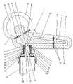
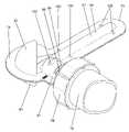
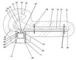
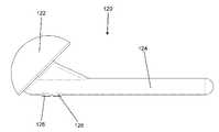
本発明の目的は、骨セメントペーストを硬化させることによりスペーサを製造するための装置であって、このスペーサは、関節の関節面を含む関節又は関節の一部を一時的に置換するために、特に股関節又は肩関節を一時的に置換するために医療分野で提供され、この装置は、
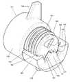
A)骨セメントペーストからスペーサを成形するための注型型であって、この注型型は、骨セメントペーストを導入するための少なくとも1つの充填開口部を有する注型型と、
B)弁座であって、この弁座は、上記少なくとも1つの充填開口部の領域で上記注型型に接続されており、上記弁座は、少なくとも1つの第1の貫通部(フィードスルー)を有する一部で又は領域的に閉じたヘッド側を有し、上記少なくとも1つの第1の貫通部は、上記少なくとも1つの充填開口部に開口している弁座と、
C)上記弁座に対して回転可能であるように取り付けられ、シール面を有する弁本体であって、上記シール面は、上記弁座の上記一部で又は領域的に閉じたヘッド側の方向に向けられており、少なくとも1つの第2の貫通部が、このシール面内に配置されている弁本体と
を有し、
上記弁座及び弁本体は一緒になって弁を形成し、この弁は、弁座に対する弁本体の回転によって開位置及び閉位置に可逆的に移動可能であり、弁の開位置において、弁座の少なくとも1つの第1の貫通部及び弁本体の少なくとも1つの第2の貫通部が、少なくとも一部で互いに重なり合って(互いに上方に)位置し、骨セメントペーストにとって透過性である、弁を介した注型型内への接続を提供し、上記弁の閉位置において、上記弁座の少なくとも1つの第1の貫通部は上記弁本体のシール面によって覆われており、上記弁の閉位置において、上記注型型の少なくとも1つの充填開口部は骨セメントペーストについて覆われて閉じられており、上記弁は、上記注型型から離れた側で、骨セメントカートリッジの液密接続のためのポートに接続されているか、又は上記弁がそのようなポートを有する装置によって達成される。An object of the present invention is a device for producing a spacer by hardening a bone cement paste, wherein the spacer temporarily replaces a joint or a part of a joint including the joint surface of the joint. Provided in the medical field specifically for the temporary replacement of hip or shoulder joints, this device
A) A casting mold for molding a spacer from a bone cement paste, the casting mold having at least one filling opening for introducing the bone cement paste, and a casting mold.
B) A valve seat, the valve seat being connected to the casting mold in the region of the at least one filling opening, wherein the valve seat is at least one first penetration (feedthrough). The at least one first penetration has a valve seat that is partially or regionally closed and has an opening in the at least one filling opening.
C) A valve body that is rotatably attached to the valve seat and has a sealing surface, wherein the sealing surface is in the direction of the head side that is partially or regionally closed to the valve seat. At least one second penetration has a valve body and is located within this sealing surface.
The valve seat and the valve body together form a valve, and the valve can be reversibly moved to the open position and the closed position by the rotation of the valve body with respect to the valve seat, and the valve seat is in the open position of the valve. At least one first penetration of the valve and at least one second penetration of the valve body are located at least in part overlapping each other (above each other) and are permeable to bone cement paste through the valve. In the closed position of the valve, at least one first penetration of the valve seat is covered by a sealing surface of the valve body and in the closed position of the valve. The at least one filling opening of the cast is covered and closed with bone cement paste, and the valve is a port for liquidtight connection of the bone cement cartridge on the side away from the cast. The valve is achieved by a device that is connected to or has such a port.
液密とは、硬化していない、すなわち流動性のある骨セメントペーストが、好ましくは骨セメントの出発成分としての液体のモノマー液体も、ポートの接続部から流出したり、ポートの接続部を通り抜けたりすることができないことを意味する。 Liquid tightness means that the bone cement paste is not hardened, that is, fluid, and preferably a liquid monomer liquid as a starting component of bone cement also flows out from the connection part of the port or passes through the connection part of the port. It means that you can't do it.
骨セメントペーストについて覆われているとは、弁内の骨セメントペーストが、硬化前に弁を通って流れることができない程度に流動することが防止されていることを意味する。通常の粘度の骨セメントペーストについては、骨セメントペーストが弁内を一直線に流れることができず、自由通路の断面積が1mm未満であればこの目的のために十分である。骨セメントペーストは、「ペースト」という用語で示されるように、粘り気のある又は高粘性の流体である。骨セメントペーストの粘度は、少なくとも10Pa・sに達し、これは液体蜂蜜の粘度に相当する。加えて、骨セメントペーストは数分以内に硬化し、これは、そうなると通過がもはや不可能であることを意味する。好ましくは、骨セメントペーストが少なくとも10Pa・sの粘度を有するように構成されていてもよい。 Covered with respect to the bone cement paste means that the bone cement paste in the valve is prevented from flowing to the extent that it cannot flow through the valve before hardening. For bone cement pastes of normal viscosity, bone cement pastes cannot flow linearly in the valve and a free passage cross-sectional area of less than 1 mm is sufficient for this purpose. Bone cement paste is a viscous or highly viscous fluid, as indicated by the term "paste". The viscosity of the bone cement paste reaches at least 10 Pa · s, which corresponds to the viscosity of liquid honey. In addition, the bone cement paste hardens within minutes, which means that it is no longer possible to pass through. Preferably, the bone cement paste may be configured to have a viscosity of at least 10 Pa · s.
骨セメントペースト又は流動性のある骨セメントペーストとは、高粘度の粘稠度を有する混合された(即ち、すぐに使用できる)骨セメントペーストを意味するものと理解される。好ましくは、骨セメントの粘度は、蜂蜜の粘度に相当するか、又はそれよりもはるかに高い。流動性のある骨セメント及び骨セメントペーストという用語は、同義に使用される。 Bone cement paste or fluid bone cement paste is understood to mean a mixed (ie, ready-to-use) bone cement paste with high viscosity viscosity. Preferably, the viscosity of the bone cement corresponds to or is much higher than the viscosity of honey. The terms fluid bone cement and bone cement paste are used interchangeably.
上記注型型は、好ましくは内部が中空である。 The cast type is preferably hollow inside.
シール面が、少なくとも1つの第2の貫通部以外では閉じているように構成されていてもよい。 The sealing surface may be configured to be closed except for at least one second penetration.
また、好ましくは、上記注型型が、関節頭、特に股関節頭又は肩関節頭の負の形状(反転形状)を複製する内部を有するように構成されていてもよい。 Also, preferably, the casting may be configured to have an interior that duplicates the negative shape (reversed shape) of the head, especially the hip or shoulder head.
また、弁座が、液体不透過的に注型型の注型型壁に接続されるように構成されていてもよい。 The valve seat may also be configured to be liquid impermeable and connected to the casting wall.
弁座が、注型型によって画定された空洞の一端面において、円盤、特に平面円盤として構成されるようにさらに構成されていてもよい。 The valve seat may be further configured to be configured as a disk, in particular a planar disk, at one end surface of the cavity defined by the casting.
また、好ましくは、弁座及び弁本体が中空円筒状であるように構成されていてもよい。 Further, preferably, the valve seat and the valve body may be configured to have a hollow cylindrical shape.
注型型が2つの部分又は複数の部分からなり、注型型の複数の部分は、好ましくは、フランジを介して液密に互いに固定可能であるようにさらに構成されてもよい。上記注型型は、特に好ましくは2つの部分からなる。 The casting may consist of two or more portions, and the plurality of portions of the casting may be further configured to be liquidtightly fixed to each other, preferably via flanges. The casting mold is particularly preferably composed of two parts.
注型型は、高粘度の骨セメントペーストの使用をも可能にするために、10N/cm2の圧力に耐えることを意図している。The cast mold is intended to withstand a pressure of 10 N / cm2 to also allow the use of high viscosity bone cement paste.
弁座に対する弁又は弁本体の「開状態」及び「閉状態」という用語と、弁座に対する弁又は弁本体の「開位置」及び「閉位置」という用語は、同義に使用される。 The terms "open" and "closed" of the valve or valve body with respect to the valve seat and the terms "open and closed" of the valve or valve body with respect to the valve seat are used interchangeably.
本特許出願において、スペーサ又は注型型に関する方向(「近位」、「遠位」及び「側方」)の記述、並びに平面に関する記述(「矢状平面」、「正面平面」及び「横平面」)は、患者に挿入されたときの主解剖学的方向又は身体平面として理解されるであろうものと同様に使用される。例えば、「近位」とは、身体の中心に向かっての意味であり、「遠位」とは、身体の中心から離れての意味である。 In this patent application, a description of the direction ("proximal", "distal" and "lateral") regarding the spacer or casting, and a description regarding the plane ("sagittal plane", "front plane" and "horizontal plane"). ") Is used in the same way that would be understood as the main anatomical orientation or body plane when inserted into the patient. For example, "proximal" means towards the center of the body and "distal" means away from the center of the body.
ステムは、骨へ(股関節スペーサの場合には大腿骨へ)の接続のために提供され、この目的のために、好ましくは、準備された骨の近位端に、又は骨管内に導入されてもよい。 The stem is provided for connection to the bone (to the femur in the case of a hip spacer) and is preferably introduced for this purpose at the proximal end of the prepared bone or into the bone canal. May be good.
好ましくは、スペーサ、特に股関節スペーサ又は肩関節スペーサを製造するための当該装置が、少なくとも1種の抗生物質及び/又は抗真菌活性成分を付与するのに適しているように構成されていてもよい。 Preferably, the device for making spacers, in particular hip or shoulder spacers, may be configured to be suitable for imparting at least one antibiotic and / or antifungal active ingredient. ..
スペーサは、好ましくは、ポリメタクリル酸メチル(PMMA)等の生体適合性骨セメントペーストから一体的に作製されるべきであり、このPMMAは、特に好ましくは、PMMAから溶解可能な少なくとも1種の抗生物質及び/又は抗真菌剤を含む。 The spacer should preferably be made integrally from a biocompatible bone cement paste such as polymethyl methacrylate (PMMA), which PMMA is particularly preferably at least one antibiotic soluble from PMMA. Contains substances and / or antifungal agents.
好ましくは、弁座の領域的に閉じたヘッド側及び弁本体のシール面が円盤であるか、又は円盤状であるように構成されてもよい。 Preferably, the regionally closed head side of the valve seat and the sealing surface of the valve body may be disk-shaped or configured to be disk-shaped.
好ましくは、弁座が、注型型の充填開口部を画定するように構成されてもよい。 Preferably, the valve seat may be configured to define a cast filling opening.
弁座が、注型型に対して回転不能に注型型に接続されるように構成され、好ましくは、弁座が、注型型に固定的に及び/又は剛性的に接続されるように構成されてもよい。 The valve seat is configured to be non-rotatably connected to the casting with respect to the casting, preferably the valve seat is fixedly and / or rigidly connected to the casting. It may be configured.
このようにして、注型型に対する骨セメントペーストのための弁座のシール又は接続が、構造的に単純であり、従って安価な方法で達成されうる。 In this way, the sealing or connection of the valve seat for the bone cement paste to the casting can be achieved in a structurally simple and therefore inexpensive manner.
弁が手動で操作可能であり、好ましくは当該装置の外部から手動で操作可能であり、弁本体は、特に好ましくは弁座に対して手動で回転可能であり、弁は、回転によって閉位置から開位置へ、及び開位置から閉位置へ移動可能であるようにさらに構成されてもよい。 The valve is manually operable, preferably manually operable from outside the device, the valve body is particularly preferably manually rotatable with respect to the valve seat, and the valve is rotated from the closed position by rotation. It may be further configured to be movable to and from the open position.
このようにして、骨セメントカートリッジを交換又は着脱するために、当該装置の弁は、外部から便利に操作することができる。 In this way, the valve of the device can be conveniently operated from the outside in order to replace or attach / detach the bone cement cartridge.
また、弁が、ポートに接続されたセメントカートリッジの回転又は傾斜によって操作可能であり、この目的のために上記ポートは、好ましくは弁本体に配置されているように構成されてもよい。 Also, the valve can be operated by rotating or tilting the cement cartridge connected to the port, and for this purpose the port may be configured to be preferably located in the valve body.
弁座の少なくとも1つの第1の貫通部が、弁の閉位置において、弁本体のシール面で覆われており、弁座の領域的に閉じたヘッド側と弁本体のシール面は、好ましくは最大2mm、特に好ましくは最大1mm、さらに特に好ましくは最大0.5mmの間隔で互いに離間しているようにさらに構成されてもよい。 At least one first penetration of the valve seat is covered with a sealing surface of the valve body at the valve closed position, and the regionally closed head side of the valve seat and the sealing surface of the valve body are preferably. It may be further configured to be spaced apart from each other at intervals of up to 2 mm, particularly preferably up to 1 mm, and even more preferably up to 0.5 mm.
このようにして、注型型内に充填された骨セメントペースト(流動性のある骨セメント)が、弁が閉じているときに弁を介して注型型から再び排出されることができないことを確実にすることができる。骨セメントペーストがスプルーの領域でこのような厚さ又は断面を持って硬化した場合、スペーサが硬化した後、その骨セメントは容易に手動で破断又は切断することができ、鋸で分離する必要はない。このような厚さのスプルーは、OP中のOP手順を大幅に遅らせることがないため、無害である。 In this way, the bone cement paste (fluid bone cement) filled in the casting cannot be drained again from the casting through the valve when the valve is closed. You can be sure. If the bone cement paste hardens with such a thickness or cross section in the area of sprue, the bone cement can be easily manually broken or cut after the spacer has hardened and needs to be separated with a saw. do not have. Sprues of such thickness are harmless as they do not significantly delay the OP procedure during OP.
また、弁本体が、弁座に対して回転軸の周りに回転可能であるように取り付けられ、この回転軸は、弁本体のシール面に対して垂直に延びるか、又はこの回転軸は、弁本体のシール面の回転対称軸に沿って延びるように構成されてもよい。 Also, the valve body is mounted so that it is rotatable about a rotation axis with respect to the valve seat, the rotation axis extends perpendicular to the sealing surface of the valve body, or the rotation axis is a valve. It may be configured to extend along the axis of rotational symmetry of the sealing surface of the body.
その結果、弁を通って流れる骨セメントペーストは、回転によって弁本体から切断されたり、ねじ切られたりすることができる。これにより、滑らかな切断面が得られ、剪断時の力の印加は少なくなる。骨セメントカートリッジの回転は、さらに、骨セメントペーストの剪断にも使用されてよい。回転軸は、弁本体のシール面の回転対称軸に沿って延びることが好ましい。回転軸が弁本体のシール面に対して垂直に延びる場合、弁は、(例えば、ビール用の)タップのように構成されてもよい。 As a result, the bone cement paste flowing through the valve can be cut or threaded from the valve body by rotation. As a result, a smooth cut surface is obtained, and the application of force during shearing is reduced. Rotation of the bone cement cartridge may also be used to shear the bone cement paste. The axis of rotation preferably extends along the axis of rotational symmetry of the sealing surface of the valve body. If the axis of rotation extends perpendicular to the sealing surface of the valve body, the valve may be configured like a tap (eg, for beer).
また、弁本体が、弁座に対して回転軸の周りに回転可能であるように取り付けられ、この回転軸は充填開口部の方向に配向しているように構成されてもよい。 Further, the valve body may be attached to the valve seat so as to be rotatable around a rotation axis, and the rotation axis may be configured to be oriented in the direction of the filling opening.
弁本体が、弁座に対して最大280°、好ましくは最大180°、特に好ましくは弁座に対して最大100°、さらに特に好ましくは弁座に対して最大90°の角度で回転可能であるようにさらに構成されてもよい。 The valve body can rotate at an angle of up to 280 ° with respect to the valve seat, preferably up to 180 °, particularly preferably up to 100 ° with respect to the valve seat, and even more preferably up to 90 ° with respect to the valve seat. It may be further configured as follows.
好ましくは、2つの貫通部が、弁座及び弁本体のそれぞれに配置され、この2つの貫通部は、好ましくは、弁座及び弁本体の円盤の中心点の周りに180°オフセットして配置され、この円盤は、弁座の領域的に閉じたヘッド側及び弁本体のシール面を形成してもよい。 Preferably, two penetrations are placed on the valve seat and valve body, respectively, and the two penetrations are preferably offset 180 ° around the center point of the disc of the valve seat and valve body. The disk may form a locally closed head side of the valve seat and a sealing surface of the valve body.
弁本体が、骨セメントカートリッジの液密接続のためのポートを有するか、又はそのようなポートに強固に接続されているようにさらに構成されてもよい。 The valve body may have or are further configured to have a port for a liquid tight connection of the bone cement cartridge or to be tightly connected to such a port.
このようにして、弁本体は、接続された骨セメントカートリッジによって操作することができる。 In this way, the valve body can be operated by the connected bone cement cartridge.
好ましいさらなる発展によれば、当該装置が、骨セメントカートリッジに接続されているか又は接続可能なアダプタ要素を有し、このアダプタ要素は、骨セメントカートリッジの内部が、アダプタ要素を介して少なくとも1つの第2の貫通部に、骨セメントペーストについて透過的に接続されているか又は接続可能であるように、ポートに着脱可能にかつ係合可能に接続されているか又は接続可能であるように構成されてもよい。 According to a preferred further development, the device has an adapter element connected to or connectable to a bone cement cartridge, wherein the interior of the bone cement cartridge has at least one first via the adapter element. Even if it is detachably and engageably connected to or configured to be connectable to the port, such that the bone cement paste is transparently connected or connectable to the penetration of 2. good.
これにより、骨セメントペーストを、開位置にある弁を介して骨セメントカートリッジから注型型内に直接的に充填することができるということが保証される。 This ensures that the bone cement paste can be filled directly into the casting from the bone cement cartridge via the valve in the open position.
本発明のさらなる発展によれば、当該装置が、骨セメントカートリッジであって、骨セメント出発成分を混合し、混合された骨セメントペーストをその骨セメントカートリッジから送達するための骨セメントカートリッジを有し、好ましくは、骨セメントカートリッジであって、ポリメタクリル酸メチル骨セメント出発成分を混合し、混合されたポリメタクリル酸メチル骨セメントペーストをその骨セメントカートリッジから送達するための骨セメントカートリッジを有し、この骨セメントカートリッジは、特に好ましくは、骨セメントを製造するための骨セメント出発成分を相互に分離した領域に含むように構成されてもよい。 According to a further development of the present invention, the device is a bone cement cartridge, comprising a bone cement cartridge for mixing the bone cement starting components and delivering the mixed bone cement paste from the bone cement cartridge. A bone cement cartridge, preferably a bone cement cartridge for mixing a polymethylmethacrylate bone cement starting component and delivering the mixed polymethylmethacrylate bone cement paste from the bone cement cartridge. The bone cement cartridge may be particularly preferably configured to contain the bone cement starting components for producing bone cement in mutually separated regions.
このようにして、当該装置は、その後、スペーサを形成するための注型型に充填される骨セメントペーストを提供することもできるので、装置はさらに完成される。 In this way, the device can also be provided with a bone cement paste that is then filled into a casting mold for forming spacers, thus further completing the device.
また、注型型がプラスチックフィルムから、若しくは実質的にプラスチックフィルムからなるように、又は注型型が、溶着され若しくは接着剤で接着された2つ以上のプラスチックフィルムから構築され、この注型型は、好ましくはPETGフィルム及び/又はポリアミドフィルム及び/又はPEフィルムから作製されるように構成されてもよい。 Also, the casting is constructed from two or more plastic films, such that the casting is from a plastic film or substantially consists of a plastic film, or the casting is welded or glued together. May be configured to be preferably made of a PETG film and / or a polyamide film and / or a PE film.
このようにして、注型型、ひいては当該装置を安価に製造することができる。上記の材料は、骨セメントペーストからスペーサを成形するのに好適である。加えて、このスペーサは、硬化後に注型型から容易に取り出すことができる。 In this way, the casting mold and, by extension, the apparatus can be manufactured at low cost. The above materials are suitable for molding spacers from bone cement paste. In addition, the spacer can be easily removed from the casting mold after curing.
用語「プラスチックフィルム」は、2mmまでの膜厚を有する二次元プラスチックを意味すると理解される。注型型のプラスチックフィルムは、カレンダー成形、又は実際には射出成形によって製造されてもよい。熱成形及びプラスチック射出成形は、注型型を成形するための可能な選択肢である。注型型の部品は、超音波溶着、高周波溶着、熱溶着、接着剤による接着よって一緒に接続されてもよい。接合方法の組み合わせも可能である。あるいは、注型型の部品は、機械的に、例えばクランプ装置によって一緒に接続されてもよい。PETGは、グリコール変性ポリエチレンテレフタレート(PET)であり、水性(粘度)があることで際立っており、射出成形に特に適している。 The term "plastic film" is understood to mean a two-dimensional plastic with a film thickness of up to 2 mm. The cast plastic film may be manufactured by calendar molding or, in fact, injection molding. Thermoforming and plastic injection molding are possible options for molding castings. The cast parts may be connected together by ultrasonic welding, high frequency welding, heat welding, or adhesive bonding. A combination of joining methods is also possible. Alternatively, the cast parts may be mechanically connected together, for example by a clamping device. PETG is a glycol-modified polyethylene terephthalate (PET), which stands out due to its water-based (viscosity) and is particularly suitable for injection molding.
上記注型型を製造するために、膜厚が500μm~2000μmのPETG、ポリアミド、ポリエチレン(PE)のプラスチックフィルムを使用してもよい。その結果、10N/cm2の圧力に数分間割れずに耐える注型型を製造することができる。In order to produce the casting mold, a PETG, polyamide, or polyethylene (PE) plastic film having a film thickness of 500 μm to 2000 μm may be used. As a result, it is possible to manufacture a casting mold that can withstand a pressure of 10 N / cm2 without cracking for several minutes.
さらに、閉じたヘッド側の少なくとも1つの第1の貫通部のすべての開口部の和が、ヘッド側の閉じた表面以下の大きさであるように、かつ、シール面の少なくとも1つの第2の貫通部のすべての開口部の和が、シール面の閉じた表面以下の大きさであるように構成されてもよい。 Further, so that the sum of all the openings of at least one first penetration on the closed head side is smaller than or equal to the closed surface on the head side, and at least one second of the sealing surface. The sum of all openings of the penetration may be configured to be less than or equal to the closed surface of the sealing surface.
これにより、弁本体が弁座に対して回転することにより、弁を安定して骨セメントペーストに対して不透過的に閉じることができることが確実になる。 This ensures that the valve body rotates with respect to the valve seat so that the valve can be stably and opaquely closed to the bone cement paste.
弁座が内側に内ねじ部を有し、弁本体が外側に一致する外ねじ部を有し、弁本体が弁座に螺合されることが可能であるようにさらに構成されてもよい。 The valve seat may be further configured to have an internal threaded portion on the inside, a valve body having an externally threaded portion that matches the outside, and the valve body to be able to be screwed onto the valve seat.
この手段により、弁本体と弁座の間の接続部で良好なシール効果を得ることができる。加えて、このようにして弁を簡単かつ安価に組み立てることができる。 By this means, a good sealing effect can be obtained at the connection portion between the valve body and the valve seat. In addition, the valve can be assembled easily and inexpensively in this way.
また、ポートが、骨セメントカートリッジの液密接続のために、弁本体内の内ねじ部又は弁本体上の外ねじ部を含み、骨セメントカートリッジのアダプタ要素又は骨セメントカートリッジに接するアダプタ要素は、好ましくは、上記内ねじ部又は外ねじ部と一致する嵌合ねじ部を有するように構成されてもよい。 Also, the port includes an internal threaded portion in the valve body or an external threaded portion on the valve body for a liquid tight connection of the bone cement cartridge, and the adapter element of the bone cement cartridge or the adapter element in contact with the bone cement cartridge is Preferably, it may be configured to have a fitting threaded portion that matches the internal threaded portion or the external threaded portion.
このようにして、一方で、ポートへの安定した液密接続が得られる可能性があり、他方では、開始時の螺合動作中又は螺合動作の終了後の回転を利用して、弁本体を弁座に対して回転させ、弁を開状態から閉状態に移動させたり、弁を閉状態から開状態に移動させたりすることができる。 In this way, on the one hand, a stable liquidtight connection to the port may be obtained, and on the other hand, the valve body may take advantage of the rotation during the screwing operation at the start or after the end of the screwing operation. Can be rotated with respect to the valve seat to move the valve from the open state to the closed state or the valve from the closed state to the open state.
適切なねじ部を使用することで、弁が閉じている状態でのみ骨セメントカートリッジを取り外すことができ、骨セメントカートリッジが接続されている状態でのみ弁を開くことができることによって、特に、当該装置の追加の安全機能を達成することができる。 With proper threaded parts, the bone cement cartridge can be removed only when the valve is closed, and the valve can be opened only when the bone cement cartridge is connected, especially by the device. Additional safety features can be achieved.
上記弁本体の内ねじ部若しくは弁本体上の外ねじ部が右ねじ部であり、弁が弁本体の同方向の右方向への回転によって閉位置から開位置に移動可能であり、弁が弁本体の異方向の左方向への回転によって開位置から閉位置に移動可能であるように構成されてもよく、又は
上記弁本体の内ねじ部若しくは弁本体上の外ねじ部が左ねじ部であり、弁が弁本体の同方向の左方向への回転によって閉位置から開位置に移動可能であり、弁が弁本体の異方向の右方向への回転によって開位置から閉位置に移動可能であるように構成されてもよく、又は
上記弁座の内ねじ部、並びに弁本体の内ねじ部及び外ねじ部がすべて左ねじ部、若しくはすべて右ねじ部であり、上記ポートへの骨セメントカートリッジの液密接続のためのアダプタ要素の外ねじ部も好ましくは同じ回転方向を有するように構成されてもよい。The internal threaded part of the valve body or the external threaded part on the valve body is the right-handed threaded part, and the valve can be moved from the closed position to the open position by rotating the valve body in the same direction to the right, and the valve is a valve. It may be configured to be movable from the open position to the closed position by rotating the main body in a different direction to the left, or the internal threaded portion of the valve body or the external threaded portion on the valve body is a left-handed threaded portion. Yes, the valve can be moved from the closed position to the open position by rotating the valve body to the left in the same direction, and the valve can be moved from the open position to the closed position by rotating the valve body to the right in a different direction. It may be configured as such, or the internal threaded portion of the valve seat and the internal and external threaded portions of the valve body are all left-threaded or all-right-threaded and bone cement cartridges to the port. The externally threaded portion of the adapter element for liquidtight connection may also preferably be configured to have the same direction of rotation.
これらの手段の目的は、骨セメントカートリッジが螺合されていないときに弁が自動的に閉じ、骨セメントカートリッジが螺合されているときに弁が自動的に開くことを確実にすることでもある。 The purpose of these measures is also to ensure that the valve automatically closes when the bone cement cartridge is not screwed in and the valve opens automatically when the bone cement cartridge is screwed in. ..
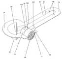
また、好ましくは、領域的に閉じたヘッド側の少なくとも1つの第1の貫通部が、シール面の少なくとも1つの第2の貫通部と同じサイズ及び形状を有するように構成されてもよい。 Also, preferably, at least one first penetration on the regionally closed head side may be configured to have the same size and shape as at least one second penetration on the sealing surface.
好ましくは、同様に、領域的に閉じたヘッド側の少なくとも1つの第1の貫通部が2つの第1の貫通部であり、シール面の少なくとも1つの第2の貫通部が2つの第2の貫通部であり、2つの第1の貫通部は、好ましくは、弁座内に、弁本体の回転軸に関して対向して配置された四分円として配置され、2つの第2の貫通部は、シール面内に、弁本体の回転軸に関して対向して配置された四分円として配置されるように構成されてもよい。 Preferably, similarly, at least one first penetration on the regionally closed head side is the two first penetrations and at least one second penetration on the sealing surface is the two second penetrations. It is a penetration, the two first penetrations are preferably arranged in the valve seat as quadrants arranged opposite each other with respect to the axis of rotation of the valve body, and the two second penetrations are It may be configured to be arranged as a quadrant arranged so as to face each other with respect to the rotation axis of the valve body in the sealing surface.
これら2つの手段のため、高粘度の骨セメントペーストのために十分な流動面積を提供することができ、別の態様では弁の漏れにつながる可能性のある弁の一方的な負荷を回避することができる。 These two means can provide sufficient flow area for high viscosity bone cement paste and, in another aspect, avoid unilateral loading of the valve which can lead to valve leakage. Can be done.
また、カラーが弁本体のシール面に配置され、このカラーが弁座の縁部に接触しているか、又はカラーが弁座の領域的に閉じたヘッド側に配置され、このカラーが弁本体の縁部に接触しているようにさらに構成されてもよい。 Also, a collar is placed on the sealing surface of the valve body, the collar is in contact with the edge of the valve seat, or the collar is placed on the regionally closed head side of the valve seat, and this collar is on the valve body. It may be further configured to be in contact with the edges.
このようにして、弁本体を弁座に安定して案内することができる。弁本体の所定のねじ部長さの場合、少なくとも1つの第2の貫通部の位置は、少なくとも1つの第1の貫通部に関してさらに正確に規定されてもよい。 In this way, the valve body can be stably guided to the valve seat. For a given threaded length of the valve body, the location of at least one second penetration may be more precisely defined with respect to at least one first penetration.
この場合には、放射状に配向されたレバーが、カラーに隣接して弁本体の周方向表面上に配置されるように構成されてもよい。 In this case, the radially oriented levers may be configured to be placed adjacent to the collar on the circumferential surface of the valve body.
さらに、レバーが弁本体上に配置され、このレバーが、弁本体の回転軸に関して半径方向の範囲を有し、このレバーは、好ましくは、注型型内のオリフィス又は弁座内のオリフィスを通って突出し、注型型内のオリフィスは、任意に、弁座との接続領域内に配置され、このオリフィスは、レバーによって弁座内で弁本体を回転させることにより、弁が開位置から閉位置へ、及び閉位置から開位置へと移動されうるような寸法を有し、特に好ましくは、このオリフィスは、弁本体が弁座に対して最大90°回転されうるような寸法を有するように構成されてもよい。 Further, a lever is placed on the valve body, which has a radial range with respect to the axis of rotation of the valve body, which preferably passes through an orifice in the casting or an orifice in the valve seat. An orifice in the casting mold is optionally located in the connection area with the valve seat, which is rotated from the open position to the closed position by rotating the valve body in the valve seat by a lever. The orifice is sized so that it can be moved from the closed position to the open position, and particularly preferably, the orifice is sized so that the valve body can be rotated up to 90 ° with respect to the valve seat. May be done.
その結果、弁は外部から便利に手動で操作することができる。このレバーを使用して、弁本体を弁の開位置から閉位置に回転させることができる。 As a result, the valve can be conveniently manually operated from the outside. This lever can be used to rotate the valve body from the open position to the closed position of the valve.
好ましいさらなる発展によれば、弁本体及び弁座がプラスチック、特に熱可塑性プラスチックから作製され、弁座は、好ましくは、注型型の壁に接着剤で接着されるか、又は溶着されるように構成されてもよい。 According to a preferred further development, the valve body and valve seat are made of plastic, especially thermoplastic, so that the valve seat is preferably glued or welded to the cast wall. It may be configured.
このようにして、弁、ひいては当該装置は、安価に、衛生的な使い捨て製品として製造することができる。 In this way, the valve, and thus the device, can be inexpensively manufactured as a hygienic disposable product.
好ましくは、弁座が、その外側にリブを有し、そのリブが注型型との形態嵌め(フォームフィッティング)接続に入るか、又は入ってもよいように構成されていてもよい。 Preferably, the valve seat may have ribs on its outside and the ribs may be configured to enter or may enter a form fitting connection with the cast.
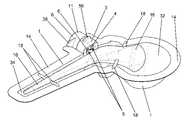
また、注型型が、保持ピンを受けるための、注型型の内部チャンバから始まる少なくとも3つ又は4つの空洞を有し、この注型型が、好ましくは、2つの部分からなり、空洞は、好ましくは、2つの部分からなる注型型の少なくとも1つの部分の縁部又はフランジ内に配置されるように構成されてもよい。 Also, the casting has at least three or four cavities starting from the casting's internal chamber for receiving the retaining pins, the casting preferably consisting of two parts, the cavities , Preferably configured to be located within the edges or flanges of at least one portion of the two-part cast.
これらの空洞を使用して、金属製の芯体を補強としてスペーサ内に配置し、正確に位置決めすることができる。 These cavities can be used to place a metal core as a reinforcement in the spacer for accurate positioning.
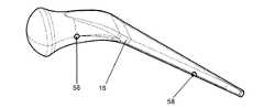
さらに、当該装置が、注型型内に配置するための金属製の芯体を有し、この金属製の芯体は、好ましくは、保持ピンを受けるための穴を有し、この穴は、特に好ましくは、スペーサの摺動面を成形するための注型型の領域に配置されておらず、さらに特に好ましくは、穴は、スペーサのステムを成形するための注型型の領域に配置されているように構成されてもよい。 Further, the device has a metal core for placement in the casting mold, which preferably has a hole for receiving a holding pin, which is a hole. Particularly preferably, the holes are not located in the casting area for forming the sliding surface of the spacer, and even more preferably, the holes are arranged in the casting area for forming the stem of the spacer. It may be configured as such.
スペーサのステムは、骨との接続を提供するのに役立ち、埋め込み時に骨セメントで覆われる。 The stem of the spacer helps to provide a connection with the bone and is covered with bone cement during implantation.
金属製の芯体は、好ましくは生体適合性金属又は生体適合性金属合金からなり、特に好ましくは外科用鋼からなる。 The metal core is preferably made of a biocompatible metal or a biocompatible metal alloy, and particularly preferably made of surgical steel.
また、当該装置が、注型型内に金属製の芯体を保持するための少なくとも3本又は4本の保持ピンを有するように構成されてもよい。 The device may also be configured to have at least 3 or 4 retaining pins for retaining the metal core in the casting mold.
金属製の芯体は、スペーサを安定化させるのに役立ち、従って、処置された関節のより良い使用性を確保する。 The metal core helps stabilize the spacer and thus ensures better usability of the treated joint.
金属製の芯体は、注型型内の所定の位置に保持ピンによって保持される。このようにして、金属製の芯体の周りの骨セメントジャケットの厚さが定められる。保持ピンは、好ましくは生体適合性のプラスチック材料から作製される。ポリメタクリル酸メチルがこれに特に好適である。ポリメタクリル酸メチルの保持ピンは、骨セメントペーストに不可逆的に結合する。骨セメントペーストの硬化後、スペーサから突出した保持ピンは、単に切断される。スペーサ内に位置する保持ピンの残留物は、スペーサの中に残る。 The metal core is held in place within the casting mold by retaining pins. In this way, the thickness of the bone cement jacket around the metal core is determined. The retaining pin is preferably made of a biocompatible plastic material. Polymethyl methacrylate is particularly suitable for this. The retaining pin of polymethyl methacrylate irreversibly binds to the bone cement paste. After the bone cement paste has hardened, the retaining pins protruding from the spacer are simply cut. Residues of retaining pins located within the spacer remain in the spacer.
また、空気又はガスが注型型の内部から通って逃げることができる少なくとも1つの通気口が注型型に設けられ、好ましくは、この少なくとも1つの通気口のうちの少なくとも1つ、特に好ましくは少なくとも1つの通気口のそれぞれが、スペーサの摺動面又は関節頭を形成する注型型の領域内に配置されるように構成されてもよい。 Also, the casting is provided with at least one vent that allows air or gas to escape through the interior of the casting, preferably at least one of the at least one vent, particularly preferably. Each of the at least one vent may be configured to be located within a casting area forming a sliding surface or articular head of the spacer.
このようにして、骨セメントペーストが導入されるときに、空気又はガスが注型型の内部から逃げることができる。巻き込まれた空気、ひいてはスペーサの表面上の凹凸は、それによって回避される可能性がある。 In this way, air or gas can escape from the inside of the cast when the bone cement paste is introduced. Entrained air and thus unevenness on the surface of the spacer can be avoided thereby.
本発明の根底にある目的は、関節の関節面を含む関節又は関節の一部、特に股関節又は肩関節を一時的に置換するためのスペーサを製造する方法であって、この方法は本発明に係る装置を用いて行われ、この方法は、以下の時系列的な
A)骨セメントカートリッジを上記装置のポートに液密に接続する工程と、
B)骨セメントペーストを、開位置にある弁を通して骨セメントカートリッジから注型型に注入する工程と、
C)弁本体を弁座に対して回転させ、弁を閉位置に移動させ、弁座に対する弁本体の回転によって、弁座の領域的に閉じたヘッド側の少なくとも1つの第1の貫通部で骨セメントペーストを剪断する工程と、
D)骨セメントカートリッジをポートから取り外す工程と、
E)注型型内で骨セメントペーストを硬化させる工程と、
F)結果として成形され、硬化したスペーサを注型型から取り出す工程と
を備える方法によっても達成される。An object underlying the present invention is a method of manufacturing a spacer for temporarily replacing a joint or a part of a joint including the joint surface of the joint, particularly a hip joint or a shoulder joint, and this method is described in the present invention. This method is performed using such a device, in which the following time-series A) bone cement cartridge is liquidtightly connected to the port of the device.
B) The process of injecting the bone cement paste from the bone cement cartridge into the casting mold through the valve in the open position,
C) Rotate the valve body with respect to the valve seat, move the valve to the closed position, and rotate the valve body with respect to the valve seat at at least one first penetration on the head side that is regionally closed to the valve seat. The process of shearing bone cement paste and
D) The process of removing the bone cement cartridge from the port,
E) The process of hardening the bone cement paste in the casting mold,
F) It is also achieved by a method comprising a step of removing the resulting molded and cured spacer from the casting mold.
上記スペーサは、医療用途を意図している。本発明に係る方法は、患者への埋め込みを含むものではなく、単にスペーサの形成を含むにすぎない。工程F)の後、スペーサは、バリを切り落とし、平滑化し、サンディングし、洗浄し、研磨し、及び/又は所々粗面化することができる。 The spacer is intended for medical use. The method according to the present invention does not include implantation in a patient, but merely involves the formation of spacers. After step F), the spacer can be deburred, smoothed, sanded, washed, polished, and / or roughened in places.
成形されて硬化したスペーサを工程F)で注型型から取り出すために、工程E)の後に注型型を開くことができる。 In order to remove the molded and cured spacer from the casting mold in step F), the casting mold can be opened after step E).
本発明に係る方法では、工程D)の後で工程E)の前に、以下の中間工程:
D2)新しい骨セメントカートリッジを上記装置のポートに液密に接続する工程であって、骨セメントペースト又は骨セメントペーストを製造するための出発成分がその新しい骨セメントカートリッジ内に存在する工程、
D3)弁本体を弁座に対して回転させて、弁を開位置に移動させる工程、
D4)骨セメントペーストを、新しい骨セメントカートリッジから開位置にある弁を通って注型型に注入する工程、
D5)弁本体を弁座に対して回転させ、弁を閉位置に移動させ、弁座に対する弁本体の回転によって、弁座の領域的に閉じたヘッド側の少なくとも1つの第1の貫通部で骨セメントペーストを剪断する工程、及び
D6)新しい骨セメントカートリッジをポートから取り外す工程
が進行するように構成されてもよく、
工程D2)~D6)は、好ましくは、注型型が骨セメントペーストで完全に又は必要に応じて充填されるまで、いずれの場合も骨セメントペースト又はその出発成分を含む新しい骨セメントカートリッジを用いて、1回又は複数回繰り返される。In the method according to the present invention, after step D) and before step E), the following intermediate steps are:
D2) A step of liquidally connecting a new bone cement cartridge to the port of the above device, wherein a starting component for producing the bone cement paste or the bone cement paste is present in the new bone cement cartridge.
D3) The process of rotating the valve body with respect to the valve seat to move the valve to the open position.
D4) The process of injecting bone cement paste from a new bone cement cartridge into a casting mold through a valve in the open position,
D5) Rotate the valve body with respect to the valve seat, move the valve to the closed position, and by rotating the valve body with respect to the valve seat, at least one first penetration on the head side that is regionally closed in the valve seat. The process of shearing the bone cement paste and D6) the process of removing the new bone cement cartridge from the port may be configured to proceed.
Steps D2) to D6) preferably use a new bone cement cartridge containing the bone cement paste or its starting component in each case until the cast is completely filled with bone cement paste or as needed. It is repeated once or multiple times.
このようにして、大きな容積を有する注型型が、少量の骨セメントペーストを含む複数の骨セメントカートリッジを用いて充填されてもよい。これは、例えば、大容量の股関節スペーサの製造に有利である。 In this way, the cast mold having a large volume may be filled with a plurality of bone cement cartridges containing a small amount of bone cement paste. This is advantageous, for example, in the manufacture of large capacity hip spacers.
さらに、骨セメントペーストが、工程B)の前に、好ましくは工程A)の前に、モノマー液体及びセメント粉末から骨セメントカートリッジ内で混合され、任意に、工程D3)の前に、好ましくは工程D2)の前に、この骨セメントペーストが、好ましくはモノマー液体及びセメント粉末から新しい骨セメントカートリッジ内で混合されるように構成されてもよい。 Further, the bone cement paste is mixed in the bone cement cartridge from the monomer liquid and cement powder before step B), preferably before step A), and optionally before step D3), preferably before step D3). Prior to D2), the bone cement paste may be configured to be mixed in a new bone cement cartridge, preferably from monomeric liquid and cement powder.
このようにして、混合されたばかりの骨セメントペーストをスペーサの製造に使用することができる。特にPMMA骨セメントペーストは、混合状態であればほとんど問題なく数分以上の期間保存することができる。加えて、それに応じて、抗生物質や抗真菌剤等の適切な治療用医薬活性物質は、スペーサを製造する直前にのみ、骨セメントペーストに混合されてもよい。 In this way, the freshly mixed bone cement paste can be used in the manufacture of spacers. In particular, PMMA bone cement paste can be stored for a period of several minutes or more with almost no problem if it is in a mixed state. In addition, accordingly, suitable therapeutically active agents such as antibiotics and antifungal agents may be mixed with the bone cement paste only immediately prior to the manufacture of the spacer.
さらに、骨セメントカートリッジ及び/若しくは新しい骨セメントカートリッジをポートに液密に接続するために、骨セメントカートリッジ及び/若しくは新しい骨セメントカートリッジがポートに回転されるか、又はポートに螺合され、骨セメントカートリッジ及び/若しくは新しい骨セメントカートリッジをポートから取り外すために、骨セメントカートリッジ若しくは新しい骨セメントカートリッジがポートから回転されるか、又はポートから螺合解除されるように構成されていてもよい。 In addition, the bone cement cartridge and / or the new bone cement cartridge is rotated to the port or screwed into the port to liquidally connect the bone cement cartridge and / or the new bone cement cartridge to the port. In order to remove the cartridge and / or the new bone cement cartridge from the port, the bone cement cartridge or the new bone cement cartridge may be configured to be rotated from the port or unscrewed from the port.
骨セメントカートリッジは、螺合で固定されることに加えて、例えば、バヨネット閉鎖器でポートに接続されていてもよい。 In addition to being screwed in, the bone cement cartridge may be connected to the port, for example, with a bayonet closure.
骨セメントカートリッジをポートに回転又は螺合することにより、ポートと骨セメントカートリッジとの間に液密な接続を提供することができる。加えて、この回転は、弁本体も弁座に対して回転させるか、又はその回転を引き起こしてもよい。 By rotating or screwing the bone cement cartridge into the port, a liquidtight connection can be provided between the port and the bone cement cartridge. In addition, this rotation may also rotate the valve body with respect to the valve seat or cause it to rotate.
また、弁本体を弁座に対して回転させることは、弁本体を弁座に螺合することによって、又は弁本体を弁座に対して手動で回転させることによって進行し、手動回転は、好ましくは、弁本体から半径方向に離れて延在し、注型型内又は弁座内のオリフィスを通って延在するレバーの操作によって進行するように構成されてもよい。 Further, rotating the valve body with respect to the valve seat proceeds by screwing the valve body into the valve seat or manually rotating the valve body with respect to the valve seat, and manual rotation is preferable. May be configured to extend radially away from the valve body and proceed by manipulating a lever extending in the casting or through an orifice in the valve seat.
その結果、弁は使用者によって簡単に操作可能である。 As a result, the valve can be easily operated by the user.
また、骨セメントカートリッジ又は新しい骨セメントカートリッジからの骨セメントペーストの注入が、ピストンを骨セメントカートリッジの内部に押し込むことによって進行するように構成されていてもよい。 Further, the injection of the bone cement paste from the bone cement cartridge or a new bone cement cartridge may be configured to proceed by pushing the piston into the bone cement cartridge.
このようにして、骨セメントペーストは、骨セメントカートリッジから、開放弁を通って注型型に直接注入することができる。 In this way, the bone cement paste can be injected directly from the bone cement cartridge into the casting mold through the open valve.
また、最後に、工程B)の前に、好ましくは工程A)の前に、金属製の芯体が注型型内に配置され、この金属製の芯体は、好ましくは、複数の保持ピンを介して注型型の内壁から間隔をあけて配置され、この複数の保持ピンは、特に好ましくは、金属製の芯体内の穴に、及び注型型の内壁にある保持ピンを受けるための空洞に固定されるように構成されてもよい。 Finally, prior to step B), preferably prior to step A), a metal core is placed in the casting mold, which is preferably a plurality of holding pins. Spacing from the inner wall of the cast via, the plurality of retaining pins are particularly preferably for receiving the retaining pins in the holes in the metal core and in the inner wall of the cast. It may be configured to be fixed in the cavity.
このようにして、当該装置の助けを借りて、スペーサは内部補強材を伴って構成されてもよい。この場合の骨セメントペーストは、注型型内に配置された金属製の芯体の周りを流れる。 In this way, with the help of the device, the spacer may be configured with an internal reinforcement. The bone cement paste in this case flows around a metal core placed in the casting mold.
本発明は、弁座の中で回転可能である弁本体によって、スプルーが弁本体によって剪断されるか又は大部分が剪断されることができる注型型を備えた装置を提供することが可能であり、同時に、骨セメントカートリッジからの継続的な圧力の場合には、骨セメントペーストが注型型内で圧力下に保持され続けることができ、その結果、骨セメントペーストを注型型の内部に押し付けることができると同時に骨セメントペーストが充填開口部を通って注型型から逆流するのを防ぐ程度に注型型を閉じるか、又は少なくとも残りの流路を縮小させることが可能であるという驚くべき認識に基づくものである。また、この装置によれば、骨セメントペーストが充填開口部を通って注型型から逆流できることなく、複数の骨セメントカートリッジの内容物を連続して注型型に充填することが可能となる。このようにして、少量の骨セメントしか供給しない骨セメントカートリッジを用いても、大容量のスペーサを製造することが可能となる。 The present invention is capable of providing a device with a casting mold in which the sprue can be cemented or largely sheared by the valve body, which is rotatable within the valve seat. At the same time, in the case of continuous pressure from the bone cement cartridge, the bone cement paste can continue to be held under pressure within the casting, resulting in the bone cement paste inside the casting. Surprisingly, it is possible to close the casting or at least shrink the remaining flow path to the extent that it can be pressed and at the same time prevent the bone cement paste from flowing back from the casting through the filling opening. It is based on the recognition of power. Further, according to this device, the contents of a plurality of bone cement cartridges can be continuously filled into the casting mold without allowing the bone cement paste to flow back from the casting mold through the filling opening. In this way, it is possible to manufacture a large-capacity spacer even by using a bone cement cartridge that supplies only a small amount of bone cement.
骨セメントペースト、特に高粘度でない骨セメントペーストは、クロージャー弁又は閉鎖弁を通って注型型から流出することができない。骨セメントが流出することに起因してスペーサに欠陥が形成されることは、結果として防止される。さらには、本発明に係る手段は、骨セメントカートリッジ内に残された骨セメントペーストの残留物が、注型型内の骨セメントペーストから分離されることを確実にする。それゆえ、骨セメントペーストの硬化が完了すると、スプルーを機械的に、例えば鋸で切断するなどして分離する必要はもはやなくなる。残った細い接続部があってもそれは簡単に破断又は切断することができる。これにより、OP担当者の時間と労力を節約することができる。 Bone cement pastes, especially non-viscous bone cement pastes, cannot flow out of the casting through closure or closure valves. As a result, the formation of defects in the spacer due to the outflow of bone cement is prevented. Furthermore, the means according to the present invention ensure that the residue of the bone cement paste left in the bone cement cartridge is separated from the bone cement paste in the casting mold. Therefore, once the bone cement paste has hardened, it is no longer necessary to separate the sprue mechanically, for example by cutting it with a saw. Even if there is a thin connection left, it can be easily broken or cut. This can save the time and effort of the OP person in charge.
スペーサのスプルーは、弁座と弁本体との充填開口部によって形成される。弁の開位置から弁の閉位置へと弁本体を弁座に対して回転させると、注型型は骨セメントペーストに対して不透過的に閉鎖される。これは、弁座と弁本体と、すなわちスプルー形成部分によって形成されたスプルーが同時に弁として機能するということを意味する。複雑な追加の弁は必要ない。 The spacer sprue is formed by the filling opening between the valve seat and the valve body. When the valve body is rotated relative to the valve seat from the valve open position to the valve closed position, the cast is opaquely closed to the bone cement paste. This means that the valve seat and the valve body, that is, the sprue formed by the sprue forming portion, function as a valve at the same time. No complicated additional valves are needed.
弁本体は、弁本体の外側に設けられたレバーによって、弁座に対して手動で回転させてもよい。また、回転は、有利には、骨セメントカートリッジが螺合解除されるときに、弁本体が骨セメントカートリッジによって共回転されることによって進行してもよい。しかしながら、ここでは、閉鎖が信頼性の高いものになるように、及び弁本体を弁座から完全に回転させることはできないように、限界停止が、弁座に対する弁本体の回転運動を制限することが必要である。 The valve body may be manually rotated with respect to the valve seat by a lever provided on the outside of the valve body. Also, the rotation may advantageously proceed by co-rotating the valve body with the bone cement cartridge when the bone cement cartridge is unscrewed. However, here, the limit stop limits the rotational movement of the valve body with respect to the valve seat so that the closure is reliable and the valve body cannot be completely rotated from the valve seat. is required.
当該装置を用いて製造されたスペーサは、有利には、2種以上の微生物による感染、特に問題のある微生物による感染が存在する二期的感染部位再置換に関して使用されてもよい。 Spacers produced using the device may advantageously be used for infections with more than one type of microorganism, particularly for two-stage infection site revisions where infections with problematic microorganisms are present.
本発明に係る例示的な装置は、
a)ポリメタクリル酸メチル骨セメント成分を混合し、混合されたポリメタクリル酸メチル骨セメントペーストを送達するための骨セメントカートリッジと、
b)骨セメントカートリッジのカートリッジヘッドに接続されているか又は接続可能なアダプタ要素であって、このアダプタ要素は可逆的な係合可能な接続を形成してもよく、このアダプタ要素は、上記セメントカートリッジの内部を周囲に液体透過的に接続する貫通部を有するアダプタ要素と、
c)骨セメントペーストを導入するための充填開口部を有する、プラスチックフィルムから作製される中空の注型型と、
d)寸法的に安定した中空円筒状の弁座であって、
d1)この弁座は、上記骨セメントペーストを導入するための注型型の充填開口部に回転不能に配置されており、
d2)上記寸法的に安定した弁座は、注型型の壁に液体不透過的に接続されており、
d3)上記注型型の空洞を画定する端面において、上記寸法的に安定した弁座が、上記注型型の内部を周囲に液体透過的に接続する少なくとも1つの第1の貫通部を有する円盤として構成され、この少なくとも1つの第1の貫通部の領域は、上記弁座の円盤領域の最大50パーセントを占めるのみであり、
d4)上記弁座は内側に内ねじ部を有する、弁座と、
e)寸法的に安定した中空円筒状の弁本体であって、
e1)この弁本体は、上記中空円筒の外側に外ねじ部を有し、この外ねじ部は、上記寸法的に安定した弁座の内ねじ部と螺合可能であり、
e2)螺合により上記アダプタ要素に可逆的に接続可能な内ねじ部又は内ねじ部の一部が、上記弁本体の中空円筒の内側に配置されており、
e3)上記弁本体が、上記注型型の空洞に面し、円盤の形態をとる一方の端面に、上記少なくとも1つの第2の貫通部を有し、この少なくとも1つの第2の貫通部の領域は、弁本体の円盤領域の最大50パーセントを占めるのみであり、
e4)上記少なくとも1つの第2の貫通部は、上記寸法的に安定した弁座の少なくとも1つの第1の貫通部とほぼ同一のサイズ及び形状を有する弁本体と
から構成されてもよく、
f)上記寸法的に安定した弁座に螺合された後、弁本体は、上記少なくとも1つの第2の貫通部が上記少なくとも1つの第1の貫通部の上方に位置し、注型型の内部から周囲又は上記骨セメントカートリッジへの液透過性接続が生成されるように開位置に回転され、そして、少なくとも1つの第2の貫通部が、少なくとも1つの第1の貫通部と重ならないように、又は、少なくとも1つの第1の貫通部を覆わないように閉位置に回転可能である。An exemplary device according to the present invention is
a) A bone cement cartridge for mixing polymethylmethacrylate bone cement components and delivering the mixed polymethylmethacrylate bone cement paste, and
b) An adapter element connected to or connectable to the cartridge head of a bone cement cartridge, the adapter element may form a reversible engageable connection, the adapter element being the cement cartridge described above. An adapter element with a penetration that transparently connects the interior of the
c) Hollow castings made from plastic film with filling openings for introducing bone cement paste, and
d) A dimensionally stable hollow cylindrical valve seat.
d1) This valve seat is non-rotatably arranged in the casting-type filling opening for introducing the bone cement paste.
d2) The dimensionally stable valve seat is liquid-impermeablely connected to the casting wall.
d3) At the end face defining the casting cavity, the dimensionally stable valve seat has at least one first penetration that liquid-permeablely connects the interior of the casting to the surroundings. The area of this at least one first penetration section occupies up to 50 percent of the disk area of the valve seat.
d4) The valve seat has an internal threaded portion inside, and the valve seat and
e) A dimensionally stable hollow cylindrical valve body,
e1) This valve body has an externally threaded portion on the outside of the hollow cylinder, and this externally threaded portion can be screwed with the internally threaded portion of the dimensionally stable valve seat.
e2) A part of the internal threaded portion or the internal threaded portion that can be reversibly connected to the adapter element by screwing is arranged inside the hollow cylinder of the valve body.
e3) The valve body faces the casting cavity and has at least one second penetration on one end face in the form of a disk, of the at least one second penetration. The area occupies up to 50 percent of the disk area of the valve body and
e4) The at least one second penetration may be composed of a valve body having substantially the same size and shape as the at least one first penetration of the dimensionally stable valve seat.
f) After being screwed into the dimensionally stable valve seat, the valve body is of the cast type, with the at least one second penetration located above the at least one first penetration. Rotated to the open position to create a liquid permeable connection from the inside to the perimeter or to the bone cement cartridge, and so that at least one second penetration does not overlap with at least one first penetration. Or can be rotated to a closed position so as not to cover at least one first penetration.
注型型の空洞への骨セメントペーストの注入が完了すると、弁本体は、上記弁本体の少なくとも1つの第2の貫通部が、上記寸法的に安定した弁座の少なくとも1つの第1の貫通部の上方にもはや位置していないか、又は上記寸法的に安定した弁座の少なくとも1つの第1の貫通部と位置合わせされていないように、手動で回転させられる。このようにして、注型型の空洞は液体不透過的に閉鎖される。その結果、高粘度でない骨セメントペーストであっても、注型型から流出することができない。 Upon completion of the injection of the bone cement paste into the cast cavity, the valve body has at least one second penetration of the valve body into at least one first penetration of the dimensionally stable valve seat. It is manually rotated so that it is no longer located above the portion or is no longer aligned with at least one first penetration of the dimensionally stable valve seat. In this way, the cast cavity is closed in a liquid impermeable manner. As a result, even bone cement pastes that are not highly viscous cannot flow out of the casting mold.
本発明に係る装置を用いてスペーサを製造するための本発明に係る例示的な方法は、以下の連続した工程:
a)注型型を準備する工程と、
b)骨セメントペーストが形成されるまで骨セメントカートリッジ内で骨セメント粉末をモノマー液体と混合する工程であって、この骨セメントカートリッジは、カートリッジヘッド上に、カートリッジの内部に液体透過的に接続されたアダプタ要素を有する工程と、
c)アダプタ要素を弁本体の内ねじ部に螺合することにより、骨セメントカートリッジを注型型に液体透過的に接続する工程と、
d)圧出装置の助けを借りて、骨セメントペーストを骨セメントカートリッジから注型型内に注入する工程であって、この骨セメントペーストは、注型型の空洞内の空気を排出し、排出された空気は、好ましくは、注型型の空洞から、少なくとも1つの通気口を介して周囲に出てくる工程と、
e)骨セメントカートリッジをアダプタ要素と共に弁本体から回転させる工程であって、弁本体は弁の開位置から閉位置に回転され、それにより、骨セメントペーストが注型型の空洞から弁を通って周囲に出てくることができないように、少なくとも1つの第1の貫通部と少なくとも1つの第2の貫通部とがもはや互いに重なり合って位置しないようにする工程と、
f)骨セメントカートリッジを注型型から取り外す工程と、
g)骨セメントペーストを注型型内で硬化させる工程と、
h)骨セメントペーストが硬化した後、注型型を開く工程と、
i)スペーサを取り出す工程と
を備えてもよい。An exemplary method according to the invention for manufacturing a spacer using the apparatus according to the invention is the following sequence of steps:
a) The process of preparing the casting mold and
b) The step of mixing the bone cement powder with the monomeric liquid in the bone cement cartridge until the bone cement paste is formed, the bone cement cartridge is liquid-permeablely connected to the inside of the cartridge on the cartridge head. And the process with the adapter element
c) The process of connecting the bone cement cartridge to the casting mold in a liquid-permeable manner by screwing the adapter element into the internal threaded part of the valve body.
d) Injecting bone cement paste from a bone cement cartridge into a casting mold with the help of a presser, the bone cement paste expels and expels air from the casting cavity. The created air is preferably discharged from the casting cavity to the surroundings through at least one vent.
e) In the process of rotating the bone cement cartridge with the adapter element from the valve body, the valve body is rotated from the open position to the closed position of the valve, whereby the bone cement paste passes through the valve from the casting cavity. A step of preventing the at least one first penetration and the at least one second penetration from overlapping each other so that they cannot come out to the surroundings.
f) The process of removing the bone cement cartridge from the casting mold,
g) The process of curing the bone cement paste in the casting mold,
h) After the bone cement paste has hardened, the process of opening the casting mold and
i) It may be provided with a step of taking out the spacer.
本発明に係る装置を用いてスペーサを製造するための本発明に係る代替的な例示的方法は、以下の連続した工程:
a)注型型を準備する工程と、
b)骨セメントペーストが形成されるまで骨セメントカートリッジ内で骨セメント粉末をモノマー液体と混合する工程であって、この骨セメントカートリッジは、カートリッジヘッド上に、カートリッジの内部に液体透過的に接続されたアダプタ要素を有する工程と、
c)アダプタ要素を弁本体の内ねじ部に螺合することにより、骨セメントカートリッジを注型型に液体透過的に接続する工程と、
d)圧出装置の助けを借りて、骨セメントペーストを骨セメントカートリッジから注型型内に注入する工程であって、この骨セメントペーストは、注型型の空洞内の空気を排出し、排出された空気は、好ましくは、注型型の空洞から、少なくとも1つの通気口を介して周囲に出てくる工程と、
e)弁本体のレバーを、弁本体のねじ部の回転方向と反対に手動で回転させる工程であって、弁本体は、弁の開位置から閉位置に回転され、それにより、骨セメントペーストが注型型の空洞から弁を通って周囲に出てくることができないように、少なくとも1つの第1の貫通部と少なくとも1つの第2の貫通部とがもはや互いに重なり合って位置しないようにする工程と、
f)骨セメントカートリッジをアダプタ要素と共に弁本体から回転させる工程と、
g)骨セメントカートリッジを注型型から取り外す工程と、
h)骨セメントペーストを注型型内で硬化させる工程と、
i)骨セメントペーストが硬化した後、注型型を開く工程と、
j)スペーサを取り出す工程と
を備えてもよい。An alternative exemplary method according to the invention for making spacers using the apparatus according to the invention is the following sequence of steps:
a) The process of preparing the casting mold and
b) The step of mixing the bone cement powder with the monomeric liquid in the bone cement cartridge until the bone cement paste is formed, the bone cement cartridge is liquid-permeablely connected to the inside of the cartridge on the cartridge head. And the process with the adapter element
c) The process of connecting the bone cement cartridge to the casting mold in a liquid-permeable manner by screwing the adapter element into the internal threaded part of the valve body.
d) Injecting bone cement paste from a bone cement cartridge into a casting mold with the help of a presser, the bone cement paste expels and expels air from the casting cavity. The created air is preferably discharged from the casting cavity to the surroundings through at least one vent.
e) In the step of manually rotating the lever of the valve body in the direction opposite to the rotation direction of the threaded portion of the valve body, the valve body is rotated from the open position to the closed position of the valve, whereby the bone cement paste is formed. The step of ensuring that at least one first penetration and at least one second penetration no longer overlap each other so that they cannot exit the cast cavity through the valve. When,
f) The process of rotating the bone cement cartridge from the valve body together with the adapter element,
g) The process of removing the bone cement cartridge from the casting mold,
h) The process of curing the bone cement paste in the casting mold,
i) After the bone cement paste has hardened, the process of opening the casting mold and
j) It may be provided with a step of taking out the spacer.
本発明のさらなる例示的な実施形態を、28個の模式的な図を参照して以下で説明するが、それによって本発明を限定することはない。 Further exemplary embodiments of the invention are described below with reference to 28 schematic diagrams, which do not limit the invention.
図1~図10は、股関節用スペーサを製造するための本発明に係る装置の第1の例示的な実施形態及びその部品の様々な観点を示す図面である。 1 to 10 are drawings showing various viewpoints of the first exemplary embodiment of the apparatus according to the present invention for manufacturing a spacer for a hip joint and its components.
本発明に係る第1の装置は、股関節用スペーサを製造するために適しており、そのために提供される。当該装置は、注型型1を含む。注型型1は、2つの部分で構成されていてもよい。図1及び図3~図8は、いずれの場合も、注型型1の2つの部分のうちの1つだけを示す。図2及び図9は、注型型1の両方の部分を示す。骨セメントペースト50を導入するための充填開口部2が注型型1の片側に形成されていてもよく、この充填開口部は、注型型1の両部分において、いずれの場合も、半円筒状の開口部によって画定されていてもよい。この充填開口部2には、弁座3が配置されていてもよい。弁座3は、図8に示すように、注型型1の1つの部分にしっかりと接続されていてもよい。弁座3を注型型1により良くかつ強固に接続するために、弁座3は、その外面にパターニング、例えば弁座3の円筒状外壁の円筒軸と平行に配置される長手方向の溝を有してもよい。 The first device according to the present invention is suitable for manufacturing a spacer for a hip joint, and is provided for that purpose. The device includes casting
弁座3は、2つの第1の貫通部5以外では充填開口部2の方向に向けられたヘッド側4で閉じた中空円筒の形態をとってもよい。2つの第1の貫通部5は、四分円形状であってもよく、好ましくは、弁座3の円筒軸に関して互いに対して180°回転又はオフセットして配置されてもよい。弁本体6は、弁座3に対して軸周りに(軸方向に)回転可能であるように弁座3の内部に配置されてもよい。弁本体6は、弁座3のヘッド側4の方向に向けられたシール面7又は表面を有してもよい。弁本体6は、段付き中空円筒として構成されてもよく、その中空円筒の前部は、弁座3内に螺合されるか、又は入れられることが可能である。 The
シール面7には、2つの第2の貫通部8が配置されていてもよい。この2つの第2の貫通部8は、第1の貫通部5と同様に、四分円形状であってもよく、好ましくは、弁本体6の円筒軸に関して互いに対して180°回転して配置されてもよい。弁座3と弁本体6は一緒になって当該装置の弁を形成する。骨セメントカートリッジ10の液密接続のためのアダプタ要素9が、弁本体6に螺合されてもよい。骨セメントカートリッジ10及びアダプタ要素9は、本発明に係る装置の一部であってもよい。弁本体6は、シール面7から離れたその開放側に、アダプタ要素9を接続するためのポート11として形成されていてもよい。 Two second penetrating
骨セメントカートリッジ10は、その前面側に、骨セメントカートリッジ10から骨セメントペースト50を送達するための送達開口部12を有していてもよい。送達開口部12は、アダプタ要素9内に配置され、かつ、アダプタ要素9によって画定されていてもよい。アダプタ要素9は、送達開口部12以外では、かつ任意に真空ポート44以外では、その前面側で骨セメントカートリッジ10を閉じてもよい。 The
注型型1は、プラスチックフィルムから安価に作製することができる。このプラスチックフィルムは、複数の層を有していてもよい。注型型1の2つの部分は、フランジ14を介して互いに固定されていてもよい。フランジ14を介して注型型1の2つの部分を接続することにより、注型型1は外部に対して閉じられていてもよい。注型型1には、通気口(図1~図9では見えない)が配置されていてもよい。骨セメントペースト50が充填開口部2を介して注型型1内に充填される際に、空気又はガスが、閉鎖された注型型1の内部から通気口を介して逃げることができる。 The casting
注型型1の内部には、金属製の芯体16が配置されていてもよい。金属製の芯体16は、外科用鋼又はチタンから構成されていてもよい。あるいは、理論的には、金属製の芯体16をPMMA等のプラスチック材料から作製することも可能であろう。金属製の芯体16は、保持ピン18を介して注型型1に接続されてもよい。金属製の芯体16は、骨セメントペースト50が金属製の芯体16のすぐ周りを流れることができるように、保持ピン18の助けを借りて注型型1の内壁から間隔を置いてもよい。金属製の芯体16は、スペーサの安定化をもたらす。保持ピン18は、PMMAから構成されてもよい。これは、PMMAの骨セメントペースト50と不可逆的に結合することができる。 A
弁座3は、その内側に内ねじ部20を有していてもよい。シール面7に面する弁本体6の前半分に、弁本体6は、その外側に弁座3の内ねじ部20と一致する外ねじ部22を有してもよい。弁本体6は、その外ねじ部22によって弁座3の内ねじ部20に螺合されてもよい。 The
第1の貫通部5及び第2の貫通部8は、限界停止に達するまで弁本体6を弁座3に螺合することにより、互いに重なり合うようにしてもよい。これにより、弁は開状態となる。この開状態では、骨セメントペースト50は、骨セメントカートリッジ10から第1の貫通部5及び第2の貫通部8を通って注型型1内に流入してもよい。弁本体6を弁座3に対して4分の1回転(90°だけ)させることによって、すなわち弁本体6を弁座3から螺合を緩めることによって、弁本体6のシール面7が弁座3の第1の貫通部5を覆い、弁座3のヘッド側4の閉領域が弁本体6の第2の貫通部8を覆うように、第1の貫通部5と第2の貫通部8とを互いに対してオフセットさせてもよい。これにより、弁は閉状態となる。1/4回転時の弁座3に対する弁本体6のストロークが小さいため、弁本体6と弁座3との間に生じる間隙は非常に狭く(1mm未満の幅)、高粘度のものは言うまでもなく、通常の粘度の骨セメントペースト50でもその間隙を通過することができない。これは特に、骨セメントペースト50がその間隙内でその実際の流れの方向から90°偏向しているためである。 The first penetrating
弁本体6の逆側には、ポート11内に内ねじ部24が配置されていてもよい。アダプタ要素9の前面側には、内ねじ部24と一致する外ねじ部26が形成されている。従って、アダプタ要素9は、弁本体6のポート11に螺合されてもよい。このようにして、骨セメントカートリッジ10と弁本体6との間、ひいては注型型1内への液密接続を形成することができる。弁座3の内ねじ部20、弁本体6の外ねじ部22、弁本体6の内ねじ部24、及びアダプタ要素9の外ねじ部26は、すべて同じ回転方向を有していてもよく、すなわち、これらのねじ部はすべて右ねじ部又は左ねじ部である。その結果、アダプタ要素9をポート11に螺合し、アダプタ要素9を同じ方向に回転させ続けることにより、弁を開くことができる。同時に、弁本体6は、弁座3に対してシールも提供する。 On the opposite side of the
アダプタ要素9は、アダプタ要素9上のラッチ手段28を介して、骨セメントカートリッジ10の円筒壁上の嵌合ラッチ30に接続されてもよいし、接続されていてもよい。骨セメントカートリッジ10の円筒壁をアダプタ要素9に対してシールする周方向シール48が、シールのために設けられていてもよい。 The
また、注型型1は、スペーサの関節ヘッドを形成するための関節ヘッド成形部32と、スペーサのステムを形成するためのステム成形部34とを有してもよい。さらに、注型型1の充填開口部2の領域には、弁本体6のレバー38のためのオリフィス36が配置されていてもよい。レバー38は、弁本体6に接続されていてもよい。弁本体6は、レバー38によって弁座3内で回転可能である。オリフィス36は、好ましくは、弁本体6が弁座3に対して最大で4分の1回転だけ回転可能であるように十分に正確に大きい。その結果、レバー38の助けを借りて、弁は開状態から閉状態へ、又は閉状態から開状態へと外部から手動で移動させることができる。 Further, the casting
フランジ14の領域では、注型型1内に空洞用の形状40が配置されてもよく、その形状40の中に保持ピン18が配置されてもよい。さらに、弁固定用の形状42が、注型型1の充填開口部2を画定する壁内に配置されてもよく、その形状42は、弁座3の円筒状の外側にある一致する突起56(図8参照)を受けるために設けられている。弁固定用の形状42内の突起56の係合によって、弁座3は、充填開口部2内で回転することができず、安定した接続が提供される。 In the region of the
骨セメントペースト50が混合される骨セメントカートリッジ10の内部を真空(減圧)にすることができる真空(減圧)ポート44がアダプタ要素9に配置されてもよい。その結果、骨セメントペースト50を真空下で混合することができる。 A vacuum (decompression)
骨セメントカートリッジ10の円筒状内部には、骨セメントペースト50を骨セメントカートリッジ10から弁を介して注型型1内に排出するためのピストン46が配置されていてもよい。ピストン46は、この目的のために、外側に円筒状に形成されていてもよく、2つの周方向シール54によって円筒状内部に対してシールされていてもよい。ピストン46を前進させることにより、骨セメントペースト50は、骨セメントカートリッジ10の送達開口部12から開放弁内に、又は開放弁を介して押し出されることが可能である。 A
多孔質ディスク52がアダプタ要素9内に配置されてもよい。多孔質ディスク52は、骨セメントペースト50及びその出発成分に対して不透過性である。真空ポート44は、多孔質ディスク52によって覆われていてもよい。これにより、骨セメントペースト50の出発成分としての任意の骨セメント粉末が真空ポート44内に侵入することができることを防ぐことができる。 The
本発明に係る方法の過程は、本発明に係る第1の装置を参照して、図4~図7に示されている。まず、金属製の芯体16が注型型1内に保持ピン18を用いて位置決めされてもよい。この目的のために、保持ピン18は、一端が形状40によって形成された空洞内で注型型1の2つの部分の間に配置されて保持され、他端が金属製の芯体16の一致する穴58内に配置されてもよい。その後、注型型1は閉じられてもよい。 The process of the method according to the present invention is shown in FIGS. 4 to 7 with reference to the first apparatus according to the present invention. First, the
骨セメントペースト50は、骨セメントカートリッジ10内で真空下で混合することができる。次いで、骨セメントカートリッジ10は、アダプタ要素9を用いて弁本体6のポート11に螺合することができる。アダプタ要素9を螺合する際に、限界停止に達するまで弁本体6を弁座3に螺合することにより、弁を開位置に移すことができる。図4はこの状況を示す。 The
次に、ピストン46を前進させることにより、骨セメントペースト50は、骨セメントカートリッジ10から、弁を通って、重なり合う第1の貫通部5及び第2の貫通部8を通って注型型1内に押し出される。図5はこの状況を示す。単一の骨セメントカートリッジ10からの骨セメントペースト50の体積が注型型1を完全に充填するのに十分でない場合には、レバー38を手動で操作して弁を閉じ、従って弁本体6を弁座3に対して4分の1回転させることにより、間隔をおいて新しい骨セメントカートリッジ10を取り付けることができる。第1の通路5と第2の通路8は弁の閉位置では覆われており、その間の間隙は粘性のある骨セメントペースト50が流れることができるのに十分ではないので、注型型1内に収容された骨セメントペースト50は再び流出することができない。 Next, by advancing the
ある時点で、注型型1は骨セメントペースト50で満たされる。図6はこの状況を示す。注型型1の通気口を介して、空気又はガスが注型型1から逃散している。レバー38を用いて弁を閉じることにより、骨セメントペースト50は剪断されるか、又は切断される。骨セメントカートリッジ10は、螺合解除して取り除くことができる。残っている細い接続部があれば、それは、簡単単に引き裂かれるか、又は切断される。図7はこの状況を示す。 At some point, casting
この状態で、骨セメントペースト50を注型型1内で硬化させることができる。次いで、このようにして形成されたスペーサは注型型1から取り出される。突起状の保持ピン18は切断されてもよい。弁座3及び第1の通路5に起因するスプルーがあれば、それも同様に切断して除去することができる。通気口に起因する点(尖)もまた、除去されてもよい。スペーサの表面は、研磨され、及び/又は例えば抗生物質でコーティングされてもよい。 In this state, the
股関節スペーサを成形するための注型型1の代わりに、異なるスペーサを成形するための注型型を使用することも容易に可能である。 It is also easily possible to use a casting mold for molding a different spacer instead of the casting
図11~図19は、肩関節用スペーサを製造するための本発明に係る装置の第2の例示的な実施形態及びその部品の様々な観点を示す図面である。図20及び図21は、本発明に係る方法の結果としてこのような本発明に係る第2の装置を使用して製造された肩関節スペーサを示し、その方法の工程は、図12~図21に時系列で示されている。 11 to 19 are drawings showing various viewpoints of a second exemplary embodiment of the apparatus according to the present invention for manufacturing a spacer for a shoulder joint and its components. 20 and 21 show shoulder joint spacers manufactured using such a second device according to the invention as a result of the method according to the invention, and the steps of the method are FIGS. 12-21. It is shown in chronological order.
本発明に係る第2の装置は、肩関節用スペーサ120を製造するために適しており、そのために提供される。当該装置は、注型型61を含む。注型型61は、2つの部分で構成されてもよい。図11~図13、図16、図17、及び図19は、いずれの場合も、注型型61の2つの部分のうちの1つだけを示す。図14、図15、図18は、注型型61の両方の部分を示す。骨セメントペースト50を導入するための充填開口部62が注型型61の片側に形成されていてもよく、この充填開口部は、注型型61の両部分において、いずれの場合も、半円筒状の開口部によって画定されていてもよい。この充填開口部62には、弁座63が配置されていてもよい。弁座63は、図12及び図13に示すように、注型型61の1つの部分にしっかりと接続されていてもよい。弁座63を注型型61により良好かつ強固に接続するために、弁座63は、その外面にパターニング、例えば弁座63の円筒状外壁の円筒軸と平行に配置される長手方向の溝を有してもよい。 The second device according to the present invention is suitable for manufacturing the
弁座63は、2つの第1の貫通部65以外では充填開口部62の方向に向けられたヘッド側64で閉じた中空円筒の形態をとってもよい。2つの第1の貫通部65は、四分円形状であってもよく、好ましくは、弁座63の円筒軸に関して互いに対して180°回転して配置されてもよい。弁本体66は、弁座63に対して軸周りに回転可能であるように、弁座63の内部に配置されてもよい。弁本体66は、弁座63のヘッド側64の方向に向けられたシール面67又は表面を有していてもよい。弁本体66は、段付き中空円筒として構成されていてもよく、その中空円筒の前部は、弁座63内に螺合されるか、又は入れられることが可能である。 The
シール面67には、2つの第2の貫通部68が配置されていてもよい。2つの第2の貫通部68は、第1の貫通部65と同様に、四分円形状であってもよく、好ましくは、弁本体66の円筒軸に関して互いに対して180°回転又はオフセットして配置されてもよい。弁座63と弁本体66は一緒になって当該装置の弁を形成する。骨セメントカートリッジ70の液密接続のためのアダプタ要素69が、弁本体66に螺合されてもよい。骨セメントカートリッジ70及びアダプタ要素69は、本発明に係る装置の一部であってもよい。弁本体66は、シール面67から離れたその開放側に、アダプタ要素69を接続するためのポート71として形成されていてもよい。 Two second penetrating
骨セメントカートリッジ70は、その前面側に、骨セメントカートリッジ70から骨セメントペースト50を送達するための送達開口部72を有していてもよい。送達開口部72は、アダプタ要素69内に配置されている。送達チューブ73が、骨セメントカートリッジ70の内部に配置されてもよく、この送達チューブは、骨セメントカートリッジ70の内部でミキサー75に接続されている。送達チューブ73は、アダプタ要素69内で軸方向に移動可能に案内され、回転可能に取り付けられている。骨セメントカートリッジ70の内部で骨セメントペースト50を徹底的に混合するために、送達チューブ73の移動を通して、ミキサー75を骨セメントカートリッジ70の内部で移動させてもよい。アダプタ要素69をポート71に固定する前に、送達チューブ73を所定の破断点で破断させてもよい。送達チューブ73は、周方向シール77によってアダプタ要素69に対してシールされてもよい。アダプタ要素69は、送達開口部72以外では、かつ任意に真空ポート104以外では、その前面側で骨セメントカートリッジ70を閉じてもよい。 The
注型型61は、プラスチックフィルムから安価に作製することができる。このプラスチックフィルムは、複数の層を有していてもよい。注型型61の2つの部分は、フランジ74を介して互いに固定されていてもよい。フランジ74を介して注型型61の2つの部分を接続することにより、注型型61は外部に対して閉じられていてもよい。注型型61には、通気口(図11~図19では見えない)が配置されていてもよい。骨セメントペースト50が充填開口部62を介して注型型61内に充填される際に、空気又はガスが、閉鎖された注型型61の内部から通気口を介して逃げることができる。 The casting
注型型61の内部には、金属製の芯体76が配置されていてもよい。金属製の芯体76は、外科用鋼又はチタンから構成されていてもよい。肩関節スペーサ用の金属製の芯体76は、フック状に曲げられた円筒体であってもよい。あるいは、理論的には、金属製の芯体76をPMMA等のプラスチック材料から作製することも可能であろう。金属製の芯体76は、保持ピン78を介して注型型61に接続されてもよい。金属製の芯体76は、骨セメントペースト50が金属製の芯体76のすぐ周りを流れることができるように、保持ピン78の助けを借りて、注型型61の内壁から間隔を置いてもよい。金属製の芯体76は、スペーサ120の安定化をもたらす。保持ピン78は、PMMAから構成されてもよい。これは、PMMAの骨セメントペースト50と不可逆的に結合することができる。 A
弁座63は、その内側に内ねじ部80を有してもよい。シール面67に面する弁本体66の前半分に、弁本体66は、その外側に弁座63の内ねじ部80と一致する外ねじ部82を有してもよい。弁本体66は、その外ねじ部82によって弁座63の内ねじ部80に螺合されてもよい。 The
第1の貫通部65及び第2の貫通部68は、限界停止に達するまで弁本体66を弁座63に螺合することにより、互いに重なり合うようにしてもよい。これにより、弁本体66は開状態となる。この開状態では、骨セメントペースト50は、骨セメントカートリッジ70から第1の貫通部65及び第2の貫通部68を通って注型型61内に流入してもよい。弁本体66を弁座63に対して4分の1回転(90°だけ)させることによって、すなわち弁本体66を弁座63から螺合を緩めることによって、弁本体66のシール面67が弁座63の第1の貫通部65を覆い、弁座63のヘッド側64の閉領域が弁本体66の第2の貫通部68を覆うように、第1の貫通部65と第2の貫通部68とを互いに対してオフセットさせてもよい。これにより、弁本体66は閉状態となる。1/4回転時の弁座63に対する弁本体66のストロークが小さいため、弁本体66と弁座63との間に生じる間隙は非常に狭く(1mm未満の幅)、高粘度のものは言うまでもなく、通常の骨セメントペースト50でもその間隙を通過することができない。これは特に、骨セメントペースト50がその間隙内でその実際の流れの方向から90°偏向しているためである。 The first penetrating
弁本体66の逆側には、ポート71内に内ねじ84が配置されていてもよい。アダプタ要素69の前面側には、内ねじ部84と一致する外ねじ部86が形成されている。従って、アダプタ要素69は、弁本体66のポート71に螺合されてもよい。このようにして、骨セメントカートリッジ70と弁本体66との間、ひいては注型型61内への液密接続を形成することができる。弁座63の内ねじ部80、弁本体66の外ねじ部82、弁本体66の内ねじ部84、及びアダプタ要素69の外ねじ部86は、すべて同じ回転方向を有していてもよく、すなわち、これらのねじ部はすべて右ねじ部又は左ねじ部である。その結果、アダプタ要素69をポート71に螺合し、アダプタ要素69を同じ方向に回転させ続けることにより、弁を開くことができる。同時に、弁本体66は、弁座63に対してシールも提供する。 An
アダプタ要素69は、アダプタ要素69上のラッチ手段88を介して、骨セメントカートリッジ70の円筒壁上の嵌合ラッチ90に接続されてもよいし、接続されていてもよい。骨セメントカートリッジ70の円筒壁をアダプタ要素69に対してシールする周方向シール108がシールのために設けられていてもよい。 The
注型型61は、スペーサ120のヘッド122を形成するための関節ヘッド成形部92と、スペーサ120のステム124を形成するためのステム成形部94とを有していてもよい(図20及び図21参照)。さらに、注型型61の充填開口部62の領域には、弁本体66のレバー98のためのオリフィス96が配置されていてもよい。レバー98は、弁本体66に接続されていてもよい。弁本体66は、レバー98によって弁座63内で回転可能である。オリフィス96は、好ましくは、弁本体66が弁座63に対して最大で4分の1の回転だけ回転可能であるように十分に正確に大きい。その結果、レバー98の助けを借りて、弁は、開状態から閉状態へ、又は閉状態から開状態へと外部から手動で移動させることができる。 The
フランジ74の領域では、注型型61内に空洞用の形状100が配置されてもよく、その形状100の中に保持ピン78が配置されてもよい。さらに、弁固定用の形状102が、注型型61の充填開口部62を画定する壁内に配置されてもよく、その形状102は、弁座63の円筒状の外側にある一致する突起116(図12及び図13参照)を受けるために設けられている。弁固定用の形状102内の突起116の係合によって、弁座63は、充填開口部62内で回転することができず、安定した接続が提供される。 In the region of the
骨セメントペースト50が混合される骨セメントカートリッジ70の内部を真空にすることができる真空ポート104がアダプタ要素69に配置されてもよい。その結果、骨セメントペースト50を真空下で混合することができる。 A
骨セメントカートリッジ70の円筒状内部には、骨セメントペースト50を骨セメントカートリッジ70から弁を介して注型型61内に排出するためのピストン106が配置されていてもよい。ピストン106は、この目的のために、外側に円筒状に形成されていてもよく、2つの周方向シール114によって円筒状内部に対してシールされていてもよい。ピストン106を前進させることにより、骨セメントペースト50は、骨セメントカートリッジ70の送達開口部72から開放弁内に、又は開放弁を介して押し出されることが可能である。 A
多孔質ディスク112がアダプタ要素69内に配置されてもよい。多孔質ディスク112は、骨セメントペースト50及びその出発成分に対して不透過性である。真空ポート104は、多孔質ディスク112によって覆われていてもよい。これにより、骨セメントペースト50の出発成分としての任意の骨セメント粉末が真空ポート104内に侵入することができることを防ぐことができる。 The
本発明に係る方法の過程は、本発明に係る第2の装置を参照して、図12~図21に示されている。まず、開いた注型型61が準備される。図12はこの状況を示す。次いで、金属製の芯体76が、注型型61内に保持ピン78を用いて位置決めされてもよい。この目的のために、保持ピン78は、一端が形状100によって形成された空洞内で注型型61の2つの部分の間に配置されて保持され、他端が金属製の芯体76の一致する穴内に配置されてもよい。図13はこの状況を示す。 The process of the method according to the present invention is shown in FIGS. 12 to 21 with reference to the second apparatus according to the present invention. First, an
その後、注型型61は閉じられてもよい。図14はこの状況を示す。骨セメントペースト50は、骨セメントカートリッジ70内で真空下で混合することができる。次いで、骨セメントカートリッジ70は、アダプタ要素69を用いて弁本体66のポート71に螺合することができる。アダプタ要素69を螺合する際に、限界停止に達するまで弁本体66を弁座63に螺合することにより、弁を開位置に移すことができる。図15はこの状況を示す。 After that, the casting
次に、ピストン106を前進させることにより、骨セメントペースト50は、骨セメントカートリッジ70から、弁を通って、重なり合う第1の貫通部65及び第2の貫通部68を通って注型型61内に押し出される。図16はこの状況を示す。単一の骨セメントカートリッジ70からの骨セメントペースト50の体積が注型型61を完全に充填するのに十分でない場合には、レバー98を手動で操作して弁を閉じ、従って弁本体66を弁座63に対して4分の1回転させることにより、間隔をおいて新しい骨セメントカートリッジ70を取り付けることができる。第1の通路65及び第2の通路68は、弁の閉位置では覆われており、その間の間隙は、粘性のある骨セメントペースト50が流れることができるのに十分ではないので、注型型61内に収容された骨セメントペースト50は再び流出することができない。 Next, by advancing the
ある時点で、注型型61は骨セメントペースト50で満たされる。注型型61の通気口から、空気やガスが注型型1から逃散している。レバー98を用いて弁を閉じることにより、骨セメントペースト50は剪断されるか、又は切断される。骨セメントカートリッジ70は、螺合解除して取り除くことができる。残っている細い接続部があれば、それは、簡単に引き裂かれるか、又は切断される。図17及び図18はこの状況を示す。 At some point, the casting 61 is filled with
この状態で、骨セメントペースト50を注型型61内で硬化させることができる。図19はこの状況を示す。次いで、このようにして形成されたスペーサ120は注型型1から取り出される。図20は、取り出されたスペーサ120を示す。突起状の保持ピン78は切断されてもよい。図21はこの状況を示す。弁座63及び第1の通路65に起因するスプルー126があれば、それも同様に切断して除去することができる。通気口に起因する点(尖)も同様に除去されてもよい。スペーサ120の表面は、研磨され、及び/又は例えば抗生物質でコーティングされてもよい。 In this state, the
肩関節スペーサを成形するための注型型61の代わりに、異なるスペーサを成形するための注型型を使用することも容易に可能である。 It is also easily possible to use a casting mold for molding a different spacer instead of the casting
図22~図28は、スペーサを製造するための本発明に係る装置のための弁を開位置(図22~図24)及び閉位置(図25~図28)で示す。この弁は、図1~図10に係る本発明に係る第1の装置の弁及び図11~図19に係る本発明に係る第2の装置の弁に対応するが、他のスペーサを製造するための他の注型型と共に使用されてもよい。 22-28 show valves for the apparatus of the present invention for manufacturing spacers in open positions (FIGS. 22-24) and closed positions (FIGS. 25-28). This valve corresponds to the valve of the first apparatus according to the present invention according to FIGS. 1 to 10 and the valve of the second apparatus according to the present invention according to FIGS. 11 to 19, but manufactures other spacers. May be used with other casting molds for.
この弁は、注型型(図示せず)の充填開口部に配置されてもよい弁座163を有する。弁座163は、注型型の1つの部分に強固に接続されてもよい。注型型への弁座163の接続性をより良く、より強固にするために、弁座163は、その外面にパターニング、例えば弁座163の円筒状外壁の円筒軸と平行に配置される長手方向の溝を有していてもよい。 The valve has a
弁座163は、2つの第1の貫通部165以外ではヘッド側164で閉じた中空円筒の形態をとってもよい。2つの第1の貫通部165は、四分円形状であってもよく、好ましくは、弁座163の円筒軸に関して互いに対して180°回転して配置されてもよい。弁本体166は、弁座163に対して軸周りに回転可能であるように、弁座163の内部に配置されてもよい。弁本体166は、弁座163のヘッド側164の方向に向けられたシール面167又は表面を有していてもよい。弁本体166は、段付き中空円筒として構成されていてもよく、その中空円筒の前面は、弁座163内に螺合されるか、又は入れられることが可能である。 The
シール面167には、2つの第2の貫通部168が配置されていてもよい。この2つの第2の貫通部168は、第1の貫通部165と同様に、四分円形状であってもよく、好ましくは、弁本体166の円筒軸に関して互いに対して180°回転又はオフセットして配置されてもよい。弁座163と弁本体166は一緒になって、本発明に係る装置の弁を形成する。骨セメントカートリッジ(図示せず)の液密接続のためのアダプタ要素(図示せず)が、弁本体166に螺合されてもよい。弁本体166は、シール面167から離れたその開放側に、アダプタ要素を接続するためのポート171として形成されていてもよい。 Two second penetrating
弁座163は、その内側に内ねじ部180を有していてもよい。シール面167に面する弁本体166の前半分において、弁本体166は、その外側に弁座163の内ねじ部180と一致する外ねじ部182を有していてもよい。弁本体166は、その外ねじ部182によって弁座163の内ねじ部180に螺合されてもよい。 The
第1の貫通部165及び第2の貫通部168は、限界停止に達するまで弁本体166を弁座163に螺合することにより、互いに重なり合うようにしてもよい。これにより、弁は開状態となる。この開状態(図22~図24参照)では、骨セメントペーストは、第1の貫通部165及び第2の貫通部168を通って流れてもよい。弁本体166を弁座163に対して4分の1回転(90°だけ)させることによって、すなわち弁本体166を弁座163から螺合を緩めることによって、弁本体166のシール面167が弁座163の第1の貫通部165を覆い、弁座163のヘッド側164の閉領域が弁本体166の第2の貫通部168を覆うように、第1の貫通部165と第2の貫通部168とを互いに対してオフセットさせてもよい。これにより、弁は閉状態となる(図25~図28参照)。1/4回転時の弁座163に対する弁本体166のストロークが小さいため、弁本体166と弁座163との間に生じる間隙220は非常に狭く(1mm未満の幅)、高粘度のものは言うまでもなく、通常の粘度の骨セメントペーストでも間隙220を通過することができない(図28を参照のこと)。これは特に、骨セメントペーストが間隙220の中でその実際の流れの方向から90°偏向しているためである。注型型への弁座163のより安定した回転不可能な接続を確保するために、突起216を設けてもよい。 The
弁本体166の逆側には、ポート171内に内ねじ部184が配置されていてもよい。従って、アダプタ要素(図示せず)は、弁本体166のポート171に螺合されてもよい。弁座163の内ねじ部180、弁本体166の外ねじ部182、及び弁本体166の内ねじ部184は、すべて同じ回転方向を有していてもよく、すなわち、これらのねじ部はすべて右ねじ部又は左ねじ部である。その結果、アダプタ要素をポート171に螺合し、アダプタ要素を同じ方向に回転させ続けることにより、弁を開くことができる。同時に、弁本体166は、弁座163に対してシールも提供する。 On the opposite side of the
さらには、レバー198が弁本体166に配置されてもよい。弁本体166は、レバー198によって弁座163内で回転可能である。その結果、レバー198の助けを借りて、弁は開状態から閉状態へ、又は閉状態から開状態へと外部から手動で移動させることができる。 Further, the
前述の説明、並びに特許請求の範囲、図、及び例示的な実施形態で開示された本発明の特徴は、本発明を様々な実施形態で実現するために、個別に、及び任意の組み合わせの両方で不可欠なものであってもよい。 The above description, as well as the claims, figures, and features of the invention disclosed in the exemplary embodiments, both individually and in any combination, to realize the invention in various embodiments. May be indispensable.
1、61 注型型
2、62 充填開口部
3、63、163 弁座
4、64、164 ヘッド側
5、65、165 貫通部
6、66、166 弁本体
7、67、167 シール面
8、68、168 貫通部
9、69 アダプタ要素
10、70 骨セメントカートリッジ
11、71、171 ポート
12、72 送達開口部
14、74 フランジ
16、76 金属製の芯体
18、78 保持ピン
20、80、180 内ねじ部
22、82、182 外ねじ部
24、84、184 内ねじ部
26、86 外ねじ部
28、88 ラッチ手段
30、90 嵌合ラッチ
32、92 関節ヘッド成形部
34、94 ステム成形部
36、96 オリフィス
38、98、198 レバー
40、100 空洞用の形状
42、102 弁固定用の形状
44、104 真空ポート
46、106 ピストン
48、108 シール
50 骨セメントペースト
52、112 多孔質ディスク
54、114 シール
56、116、216 突起
58 穴
73 送達チューブ
75 ミキサー
77 シール
120 スペーサ
122 ヘッド
124 ステム
126 スプルー
220 間隙1,61
Claims (29)
Translated fromJapanese骨セメントペースト(50)から前記スペーサ(120)を成形するための注型型(1、61)であって、前記注型型(1、61)は、骨セメントペースト(50)を導入するための少なくとも1つの充填開口部(2、62)を有する注型型(1、61)と、
弁座(3、63、163)であって、前記弁座(3、63、163)は、前記少なくとも1つの充填開口部の領域(2、62)で前記注型型(1、61)に接続されており、前記弁座(3、63、163)は、少なくとも1つの第1の貫通部(5、65、165)を有する領域的に閉じたヘッド側(4、64、164)を有し、前記少なくとも1つの第1の貫通部(5、65、165)は、前記少なくとも1つの充填開口部(2、62)に開口している弁座(3、63、163)と、
前記弁座(3、63、163)に対して回転可能であるように取り付けられ、シール面(7、67、167)を有する弁本体(6、66、166)であって、前記シール面(7、67、167)は、前記弁座(3、63、163)の前記領域的に閉じたヘッド側(4、64、164)の方向に向けられており、少なくとも1つの第2の貫通部(8、68、168)が、前記シール面(7、67、167)内に配置されている弁本体(6、66、166)と
を有し、
前記弁座(3、63、163)及び前記弁本体(6、66、166)は一緒になって弁を形成し、前記弁は、前記弁座(3、63、163)に対する前記弁本体(6、66、166)の回転によって開位置及び閉位置に可逆的に移動可能であり、前記弁の前記開位置において、前記弁座(3、63、163)の前記少なくとも1つの第1の貫通部(5、65、165)及び前記弁本体(6、66、166)の前記少なくとも1つの第2の貫通部(8、68、168)が、少なくとも一部で互いに重なり合って位置し、骨セメント(50)にとって透過性である、前記弁を介した前記注型型(1、61)への接続を提供し、前記弁の前記閉位置において、前記弁座(3、63、163)の前記少なくとも1つの第1の貫通部(5、65、165)は前記弁本体(6、66、166)の前記シール面(7、67、167)によって覆われており、前記弁の前記閉位置において、前記注型型(1、61)の前記少なくとも1つの充填開口部(2、62)は骨セメントペースト(50)について覆われて閉じられており、前記弁は、前記注型型(1、61)から離れた側で、骨セメントカートリッジ(10、70)の液密接続のためのポート(11、71、171)に接続されているか、又は前記弁がそのようなポート(11、71、171)を有する装置。A device for producing a spacer (120) by hardening a bone cement paste (50), wherein the spacer (120) temporarily replaces a joint or a part of a joint including the articular surface of the joint. Provided inthe medical field for the above-mentioned device
A casting mold (1, 61) for molding the spacer (120) from the bone cement paste (50), wherein the casting mold (1, 61) is for introducing the bone cement paste (50). Casting molds (1,61) having at least one filling opening (2,62) and
Valve seats (3, 63, 163), wherein the valve seats (3, 63, 163) are in the casting mold (1, 61) in the region (2, 62) of the at least one filling opening. Connected, said valve seat (3, 63, 163) has a regionally closed head side (4, 64, 164) having at least one first penetration (5, 65, 165). The at least one first penetration (5, 65, 165) is the valve seat (3, 63, 163) that is open to the at least one filling opening (2, 62).
A valve body (6, 66, 166) rotatably attached to the valve seat (3, 63, 163) and having a sealing surface (7, 67, 167), wherein the sealing surface (6, 66, 166). 7, 67, 167) are directed towards the regionally closed head side (4, 64, 164) of the valve seat (3, 63, 163) and at least one second penetration. (8, 68, 168) has a valve body (6, 66, 166) disposed within the sealing surface (7, 67, 167).
The valve seat (3, 63, 163) and the valve body (6, 66, 166) together form a valve, and the valve is the valve body (3, 63, 163) relative to the valve seat (3, 63, 163). 6, 66, 166) can be reversibly moved to the open and closed positions by rotation, and at the open position of the valve, the at least one first penetration of the valve seat (3, 63, 163). The at least one second penetration (8, 68, 168) of the portion (5, 65, 165) and the valve body (6, 66, 166) is located at least in part overlapping each other and bone cement. It provides a connection to the casting mold (1, 61) via the valve, which is permeable to (50), and at the closed position of the valve, said of the valve seat (3, 63, 163). At least one first penetration (5, 65, 165) is covered by the sealing surface (7, 67, 167) of the valve body (6, 66, 166) and in the closed position of the valve. The at least one filling opening (2, 62) of the casting mold (1, 61) is covered and closed with the bone cement paste (50) and the valve is closed with the casting mold (1, On the side away from 61), either the bone cement cartridge (10, 70) is connected to a port (11, 71, 171) for liquidtight connection, or the valve is such a port (11, 71, 171).
前記注型型(1、61)が、溶着され若しくは接着剤で接着された2つ以上のプラスチックフィルムから構築されることを特徴とする請求項1から請求項9のいずれか1項に記載の装置。The casting mold (1, 61) is made of a plastic film, or the casting mold (1, 61) is constructedfrom two or more plastic films welded or glued together. The apparatus according to any one of claims 1 to9 , wherein the apparatus is characterized by.
前記シール面(7、67、167)の前記少なくとも1つの第2の貫通部(8、68、168)のすべての開口部の和が、前記シール面(7、67、167)の閉じた表面以下の大きさであることを特徴とする請求項1から請求項10のいずれか1項に記載の装置。The sum of all openings of the at least one first penetration (5, 65, 165) on the closed head side (4, 64, 164) is the closing of the head side (4, 64, 164). It is smaller than the surface of the surface
The sum of all the openings of the at least one second penetration (8, 68, 168) of the sealing surface (7, 67, 167) is the closed surface of the sealing surface (7, 67, 167). The apparatus according to any one of claims 1 to10 , wherein the device has the following size.
前記弁本体(6、66、166)の前記内ねじ部(24、84、184)若しくは前記弁本体(6、66、166)上の前記外ねじ部が左ねじ部であり、前記弁が前記弁本体(6、66、166)の同方向の左方向への回転によって前記閉位置から前記開位置に移動可能であり、前記弁が前記弁本体(6、66、166)の異方向の右方向への回転によって前記開位置から前記閉位置に移動可能であるか、又は
前記弁座(3、63、163)の前記内ねじ部(20、80、180)、並びに前記弁本体(6、66、166)の前記内ねじ部(24、84、184)及び前記外ねじ部(22、82、182)がすべて左ねじ部、若しくはすべて右ねじ部であることを特徴とする請求項12又は請求項12及び請求項13の組み合わせに記載の装置。The internal threaded portion (24, 84, 184) of the valve body (6, 66, 166) or the external threaded portion on the valve body (6, 66, 166) is a right-hand threaded portion, and the valve is the valve. The valve body (6, 66, 166) can be moved from the closed position to the open position by rotating to the right in the same direction, and the valve is left in a different direction from the valve body (6, 66, 166). It is possible to move from the open position to the closed position by rotation in the direction, or the internal thread portion (24, 84, 184) of the valve body (6, 66, 166) or the valve body (6, 66). The external threaded portion on 166) is a left-handed threaded portion, and the valve can be moved from the closed position to the open position by rotating the valve body (6, 66, 166) in the same direction to the left. Yes, the valve can be moved from the open position to the closed position by rotating the valve body (6, 66, 166) in a different direction to the right, or the valve seat (3, 63, 163). The internal threaded portion (20, 80, 180) of the above, and the internal threaded portion (24, 84, 184) and the external threaded portion (22, 82, 182) of the valve body (6, 66, 166) are all. The device according to claim12 , or a combination of claims12 and13 , characterized inthat it is a left-hand threaded portion or an all-right-handed threaded portion.
前記領域的に閉じたヘッド側(4、64、164)の前記少なくとも1つの第1の貫通部(5、65、165)が2つの第1の貫通部(5、65、165)であり、前記シール面(7、67、167)の前記少なくとも1つの第2の貫通部(8、68、168)が2つの第2の貫通部(8、68、168)であること
を特徴とする請求項1から請求項14のいずれか1項に記載の装置。The at least one first penetration (5, 65, 165) on the regionally closed head side (4, 64, 164) is the at least one first penetration of the sealing surface (7, 67, 167). Having the same size and shape as the two penetrations (8, 68, 168) and / or the at least one first penetration (5) on the regionally closed head side (4, 64, 164). , 65, 165) are the two first penetrations (5, 65, 165) and the at least one second penetration (8, 68, 168) of the sealing surface (7, 67, 167). The apparatus according to any one of claims 1 to14 , wherein the deviceis two second penetration portions (8, 68, 168).
A)骨セメントカートリッジ(10、70)を前記装置の前記ポート(11、71、171)に液密に接続する工程と、
B)骨セメントペースト(50)を、前記開位置にある前記弁を通して前記骨セメントカートリッジ(10、70)から前記注型型(1、61)に注入する工程と、
C)前記弁本体(6、66、166)を前記弁座(3、63、163)に対して回転させ、前記弁を前記閉位置に移動させ、前記弁座(3、63、163)に対する前記弁本体(6、66、166)の回転によって、前記弁座(3、63、163)の前記領域的に閉じたヘッド側(4、64、164)の前記少なくとも1つの第1の貫通部(5、65、165)で前記骨セメントペースト(50)を剪断する工程と、
D)前記骨セメントカートリッジ(10、70)を前記ポート(11、71、171)から取り外す工程と、
E)前記注型型(1、61)内で前記骨セメントペースト(50)を硬化させる工程と、
F)結果として成形され、硬化した前記スペーサ(120)を前記注型型(1、61)から取り出す工程と
を備える方法。The method according to any one of claims 1 to22 , wherein the spacer (120) for temporarily replacing the joint or apart of the joint including the joint surface of the joint is manufactured. Performed using the device, the method comprises the following time-series A) bone cement cartridge (10, 70) liquid-tightly connected to the port (11, 71, 171) of the device.
B) A step of injecting the bone cement paste (50) from the bone cement cartridge (10, 70) into the casting mold (1, 61) through the valve in the open position.
C) The valve body (6, 66, 166) is rotated with respect to the valve seat (3, 63, 163) to move the valve to the closed position with respect to the valve seat (3, 63, 163). The rotation of the valve body (6, 66, 166) causes the at least one first penetration of the regionally closed head side (4, 64, 164) of the valve seat (3, 63, 163). The step of shearing the bone cement paste (50) in (5, 65, 165) and
D) The step of removing the bone cement cartridge (10, 70) from the port (11, 71, 171) and
E) A step of curing the bone cement paste (50) in the casting mold (1, 61), and
F) A method comprising a step of taking out the spacer (120) molded and cured as a result from the casting mold (1, 61).
D2)新しい骨セメントカートリッジ(10、70)を前記装置の前記ポート(11、71、171)に液密に接続する工程であって、骨セメントペースト(50)又は骨セメントペースト(50)を製造するための出発成分が前記新しい骨セメントカートリッジ(10、70)内に存在する工程、
D3)前記弁本体(6、66、166)を前記弁座(3、63、163)に対して回転させて、前記弁を前記開位置に移動させる工程、
D4)前記骨セメントペースト(50)を、前記新しい骨セメントカートリッジ(10、70)から前記開位置にある前記弁を通って前記注型型(1、61)に注入する工程、
D5)前記弁本体(6、66、166)を前記弁座(3、63、163)に対して回転させ、前記弁を前記閉位置に移動させ、前記弁座(3、63、163)に対する前記弁本体(6、66、166)の回転によって、前記弁座(3、63、163)の前記領域的に閉じたヘッド側(4、64、164)の前記少なくとも1つの第1の貫通部(5、65、165)で前記骨セメントペースト(50)を剪断する工程、及び
D6)前記新しい骨セメントカートリッジ(10、70)を前記ポート(11、71、171)から取り外す工程
が進行し、
工程D2)~D6)が、前記注型型(1、61)が骨セメントペースト(50)で完全に又は必要に応じて充填されるまで、いずれの場合も骨セメントペースト(50)又はその出発成分を含む新しい骨セメントカートリッジ(10、70)を用いて、1回又は複数回繰り返されることを特徴とする請求項23に記載の方法。After step D) and before step E), the following intermediate steps:
D2) A step of liquidally connecting a new bone cement cartridge (10, 70) to the port (11, 71, 171) of the device to produce a bone cement paste (50) or a bone cement paste (50). The step in which the starting component for the presence of the new bone cement cartridge (10, 70) is present,
D3) A step of rotating the valve body (6, 66, 166) with respect to the valve seat (3, 63, 163) to move the valve to the open position.
D4) A step of injecting the bone cement paste (50) from the new bone cement cartridge (10, 70) into the casting mold (1, 61) through the valve in the open position.
D5) The valve body (6, 66, 166) is rotated with respect to the valve seat (3, 63, 163) to move the valve to the closed position with respect to the valve seat (3, 63, 163). The rotation of the valve body (6, 66, 166) causes the at least one first penetration of the regionally closed head side (4, 64, 164) of the valve seat (3, 63, 163). (5, 65, 165), the step of shearing the bone cement paste (50), and D6) the step of removing the new bone cement cartridge (10, 70) from the port (11, 71, 171) proceeded.
In each case,steps D2) to D6) are performed on the bone cement paste (50) or a portion thereof until the casting molds (1, 61) are completely or as needed filled with the bone cement paste (50). 23. The method of claim23 , characterized in that it is repeated once or multiple times with a new bone cement cartridge (10, 70) containing the starting component.
Applications Claiming Priority (4)
| Application Number | Priority Date | Filing Date | Title |
|---|---|---|---|
| EP20164534.8 | 2020-03-20 | ||
| EP20164534.8AEP3881803B1 (en) | 2020-03-20 | 2020-03-20 | Device and method for producing spacers |
| EP20171303.9AEP3900680B1 (en) | 2020-04-24 | 2020-04-24 | Device and method for producing spacers with variable head |
| EP20171303.9 | 2020-04-24 |
Publications (2)
| Publication Number | Publication Date |
|---|---|
| JP2021146200A JP2021146200A (en) | 2021-09-27 |
| JP7090186B2true JP7090186B2 (en) | 2022-06-23 |
Family
ID=77746447
Family Applications (2)
| Application Number | Title | Priority Date | Filing Date |
|---|---|---|---|
| JP2021013884AActiveJP7090186B2 (en) | 2020-03-20 | 2021-01-29 | Equipment and methods for manufacturing spacers |
| JP2021019137AActiveJP7048781B2 (en) | 2020-03-20 | 2021-02-09 | Equipment and methods for manufacturing spacers with variable heads |
Family Applications After (1)
| Application Number | Title | Priority Date | Filing Date |
|---|---|---|---|
| JP2021019137AActiveJP7048781B2 (en) | 2020-03-20 | 2021-02-09 | Equipment and methods for manufacturing spacers with variable heads |
Country Status (5)
| Country | Link |
|---|---|
| US (2) | US20210290397A1 (en) |
| JP (2) | JP7090186B2 (en) |
| CN (2) | CN113491603B (en) |
| AU (2) | AU2021200566B2 (en) |
| CA (2) | CA3107869C (en) |
Families Citing this family (7)
| Publication number | Priority date | Publication date | Assignee | Title |
|---|---|---|---|---|
| JP2023039171A (en) | 2021-09-08 | 2023-03-20 | サトーホールディングス株式会社 | Printer, control method of printer, and program |
| KR102377019B1 (en)* | 2021-11-26 | 2022-03-23 | 알앤엑스(주) | Mold for applying cement to a stem for artificial hip joint, stem for artificial hip joint usable in the mold, and method for applying cement to the stem using the mold |
| CN114376771B (en)* | 2021-12-10 | 2025-06-20 | 浙江大学 | Multifunctional elbow spacer |
| USD969323S1 (en) | 2022-06-21 | 2022-11-08 | Mc Innovation Llc | Bone spacer mold system |
| CN115383866B (en)* | 2022-09-19 | 2023-07-21 | 中国路桥工程有限责任公司 | Preparation equipment of road self-protection concrete |
| KR102788545B1 (en)* | 2022-12-26 | 2025-03-31 | 전북대학교산학협력단 | A modular articulating spacer for joint infection treatment |
| GB2634288A (en)* | 2023-10-05 | 2025-04-09 | Vyrides Yiannis | Orthopaedic spacer mould |
Citations (5)
| Publication number | Priority date | Publication date | Assignee | Title |
|---|---|---|---|---|
| US20090146342A1 (en) | 2007-12-07 | 2009-06-11 | Sean Haney | Spacer mold and methods therefor |
| US20090175978A1 (en) | 2007-12-13 | 2009-07-09 | Biomet Manufacturing Corp. | Modular Articulating Cement Spacer |
| US20140348973A1 (en) | 2011-12-06 | 2014-11-27 | Christopher J. Holt | Spacer mold for orthopedic implants |
| US20170333191A1 (en) | 2016-05-17 | 2017-11-23 | G21 S.R.L. | Mould and accessories thereof destined for the forming of an orthopedic modular spacer |
| JP2019166315A (en) | 2018-03-21 | 2019-10-03 | ヘレウス メディカル ゲーエムベーハー | Thigh hip joint spacer with washing device |
Family Cites Families (50)
| Publication number | Priority date | Publication date | Assignee | Title |
|---|---|---|---|---|
| US2842798A (en)* | 1956-02-18 | 1958-07-15 | Gerdes & Co | Injection molding device for thermoplastic materials |
| DE3219008A1 (en)* | 1982-05-19 | 1983-11-24 | Horst 8162 Schliersee Wismann | CASTING DEVICE FOR DENTAL CASTING PARTS |
| US4655778A (en)* | 1985-08-12 | 1987-04-07 | Harrington Arthritis Research Center | Joint prosthesis |
| US4956141A (en)* | 1989-04-07 | 1990-09-11 | Libbey-Owens-Ford Co. | Molding process utilizing a mold release membrane |
| US5147366A (en)* | 1990-03-01 | 1992-09-15 | Pfizer Hospital Products Group, Inc. | Pressurization of bone cement surrounding an endoprosthesis |
| US5735904A (en)* | 1995-07-05 | 1998-04-07 | Pappas; Michael J. | Spacer for establishng prosthetic gap and ligamentous tension |
| US5681289A (en) | 1995-08-14 | 1997-10-28 | Medicinelodge Inc. | Chemical dispensing system |
| US6050934A (en)* | 1997-02-26 | 2000-04-18 | Cv Dynamics, Inc. | Urinary catheter having palpitatable discharge valve with protective shoulders |
| US6245111B1 (en) | 1997-05-12 | 2001-06-12 | Richard L. Shaffner | Method and apparatus for fighting infection and maintaining joint spacing in a prosthesis implant area |
| US6309208B1 (en)* | 1997-06-13 | 2001-10-30 | Synventive Molding Solutions, Inc. | Apparatus for proportionally controlling fluid delivery to a mold |
| US5997582A (en)* | 1998-05-01 | 1999-12-07 | Weiss; James M. | Hip replacement methods and apparatus |
| US6361731B1 (en)* | 1998-07-15 | 2002-03-26 | Biomet, Inc. | Method of forming a temporary implant |
| ATE343443T1 (en)* | 2001-09-21 | 2006-11-15 | Fondarex Sa | VENT VALVE DEVICE FOR CASTING MOLDS |
| US8048167B2 (en)* | 2005-08-30 | 2011-11-01 | Depuy Products, Inc. | Orthopaedic implant kit, orthopaedic surgery kit and associated method |
| JP2007190059A (en) | 2006-01-17 | 2007-08-02 | Japan Medical Materials Corp | Bone component molding unit |
| FR2898039B1 (en) | 2006-03-03 | 2008-06-27 | Ceravic Sas Soc Par Actions Si | PROVISIONAL IMPLANT COMPRISING TWO ASSETS. |
| US7867426B2 (en)* | 2006-03-23 | 2011-01-11 | Ziran Bruce H | Method of forming a temporary implant |
| CN200957119Y (en)* | 2006-08-14 | 2007-10-10 | 深圳市博实技术开发有限公司 | Urethra valve |
| GB0701662D0 (en)* | 2006-12-14 | 2007-03-07 | Blatchford & Sons Ltd | A lower limb prosthesis |
| WO2008112996A1 (en)* | 2007-03-14 | 2008-09-18 | Conformis, Inc. | Surgical tools for arthroplasty |
| US7637729B2 (en) | 2007-12-13 | 2009-12-29 | Biomet Manufacturing Corp. | Modular articulating cement spacer mold |
| US20100042213A1 (en)* | 2008-08-13 | 2010-02-18 | Nebosky Paul S | Drug delivery implants |
| RU2404726C2 (en)* | 2008-12-30 | 2010-11-27 | Федеральное государственное учреждение "Российский центр "Восстановительная травматология и ортопедия" имени академика Г.А. Илизарова Федерального агентства по высокотехнологичной медицинской помощи" | Method for treatment of joints pathology in animals |
| CN201335161Y (en)* | 2009-01-09 | 2009-10-28 | 上海上丰集团有限公司 | Structure for valve seat of stop valve |
| US8454706B2 (en) | 2009-02-25 | 2013-06-04 | Brian C. de Beaubien | Antibiotic delivery system and method for treating an infected synovial joint during re-implantation of an orthopedic prosthesis |
| US20110015754A1 (en) | 2009-07-16 | 2011-01-20 | Teknimed | Articular implant comprising at least two cavities |
| DE102010019224B3 (en)* | 2010-05-04 | 2011-10-13 | Heraeus Medical Gmbh | Discharge device for pasty masses |
| US8715365B1 (en)* | 2011-01-12 | 2014-05-06 | University Of South Florida | Injectable hip hemiarthroplasty |
| DE102011101084B3 (en)* | 2011-05-10 | 2012-11-15 | Heraeus Medical Gmbh | Mold for the preparation of spacers for endoprostheses |
| DE102012000685A1 (en) | 2012-01-17 | 2013-07-18 | Heraeus Medical Gmbh | Process for the preparation of a spacer and a mold for the production of a spacer |
| US9433506B2 (en)* | 2012-05-03 | 2016-09-06 | Zimmer, Inc. | Spacer molds for orthopedic implants |
| US20150127104A1 (en)* | 2012-05-03 | 2015-05-07 | ULTIMATE JOINT LTD. a corporation | In-situ formation of a joint replacement prosthesis |
| DE102012018596A1 (en)* | 2012-09-20 | 2014-03-20 | Heraeus Medical Gmbh | Rotary valve body for discharge device for bone cements |
| WO2014093672A1 (en)* | 2012-12-12 | 2014-06-19 | Biomet Manufacturing, Llc | Method and device for producing temporary knee joint spacers with stems of various sizes |
| DE102013209171B4 (en)* | 2013-05-17 | 2017-03-02 | Heraeus Medical Gmbh | Apparatus and method for the in situ production of articulating spacers |
| DE102013010593B4 (en)* | 2013-06-26 | 2015-12-03 | Heraeus Medical Gmbh | Process for the preparation of spacers and device for this purpose |
| US20170340445A1 (en) | 2014-12-05 | 2017-11-30 | Ceramtec Gmbh | Ceramic Spacer for the Two-Sided Replacement of Implants in Shoulder, Knee and Hip as a Result of Infections |
| DE102015104704B4 (en) | 2015-03-27 | 2016-10-06 | Heraeus Medical Gmbh | Spacer form and method of making hip spacers |
| US10433965B2 (en) | 2015-06-17 | 2019-10-08 | Joint Purification Systems Llc | Total joint replacement infection control devices and methods |
| US10696087B1 (en)* | 2015-07-14 | 2020-06-30 | Joseph D Maresh | Writing instrument |
| ITUB20160502A1 (en) | 2016-01-19 | 2017-07-19 | Ncs Lab S R L | MOLD TO REALIZE A TEMPORARY PROSTHESIS OF HIP OR SHOULDER AND RELATIVE METHOD |
| DE102016104409A1 (en)* | 2016-03-10 | 2017-09-14 | Heraeus Medical Gmbh | Storage and mixing system for pasty cement components and method therefor |
| ITUA20163045A1 (en) | 2016-04-11 | 2017-10-11 | Augusto Magagnoli | SPACIOUS DEVICE FOR THE TREATMENT OF A ARTICULATION OF THE HUMAN BODY |
| DE102016113467B4 (en)* | 2016-07-21 | 2023-01-26 | Heraeus Medical Gmbh | Bone cement applicator with three-way pressure relief valve and method of expressing a bone cement with the bone cement applicator |
| DE102016113468A1 (en)* | 2016-07-21 | 2018-01-25 | Heraeus Medical Gmbh | Bone cement applicator with three-way valve for pressure relief |
| DE102016121607B4 (en)* | 2016-11-11 | 2019-05-16 | Heraeus Medical Gmbh | Apparatus and method for storing and mixing a bone cement |
| DE102017107569A1 (en)* | 2017-04-07 | 2018-10-11 | Heraeus Medical Gmbh | Device for storing, mixing and discharging a bone cement and method therefor |
| IT201700048295A1 (en) | 2017-05-04 | 2018-11-04 | G21 S R L | Mold and method for forming an orthopedic spacer in medical cement. |
| DE102017109716B3 (en)* | 2017-05-05 | 2018-07-26 | Tobias Beck | Metal-casting mold |
| HUE051410T2 (en)* | 2018-07-02 | 2021-03-01 | Fluehs Drehtechnik Gmbh | Upper part of a valve |
- 2021
- 2021-01-29JPJP2021013884Apatent/JP7090186B2/enactiveActive
- 2021-01-29AUAU2021200566Apatent/AU2021200566B2/enactiveActive
- 2021-02-04CACA3107869Apatent/CA3107869C/enactiveActive
- 2021-02-04CACA3107860Apatent/CA3107860C/enactiveActive
- 2021-02-09JPJP2021019137Apatent/JP7048781B2/enactiveActive
- 2021-02-12AUAU2021200926Apatent/AU2021200926B2/enactiveActive
- 2021-03-16CNCN202110282001.XApatent/CN113491603B/enactiveActive
- 2021-03-16CNCN202110281952.5Apatent/CN113491601B/enactiveActive
- 2021-03-18USUS17/205,354patent/US20210290397A1/enactivePending
- 2021-03-18USUS17/205,221patent/US11998451B2/enactiveActive
Patent Citations (5)
| Publication number | Priority date | Publication date | Assignee | Title |
|---|---|---|---|---|
| US20090146342A1 (en) | 2007-12-07 | 2009-06-11 | Sean Haney | Spacer mold and methods therefor |
| US20090175978A1 (en) | 2007-12-13 | 2009-07-09 | Biomet Manufacturing Corp. | Modular Articulating Cement Spacer |
| US20140348973A1 (en) | 2011-12-06 | 2014-11-27 | Christopher J. Holt | Spacer mold for orthopedic implants |
| US20170333191A1 (en) | 2016-05-17 | 2017-11-23 | G21 S.R.L. | Mould and accessories thereof destined for the forming of an orthopedic modular spacer |
| JP2019166315A (en) | 2018-03-21 | 2019-10-03 | ヘレウス メディカル ゲーエムベーハー | Thigh hip joint spacer with washing device |
Also Published As
| Publication number | Publication date |
|---|---|
| JP2021146200A (en) | 2021-09-27 |
| CN113491601A (en) | 2021-10-12 |
| AU2021200926A1 (en) | 2021-10-07 |
| CN113491603A (en) | 2021-10-12 |
| US11998451B2 (en) | 2024-06-04 |
| CA3107869C (en) | 2023-04-18 |
| AU2021200566B2 (en) | 2022-06-02 |
| JP2021146204A (en) | 2021-09-27 |
| AU2021200926B2 (en) | 2022-06-02 |
| AU2021200566A1 (en) | 2021-10-07 |
| US20210290397A1 (en) | 2021-09-23 |
| CN113491603B (en) | 2024-07-16 |
| CA3107869A1 (en) | 2021-09-20 |
| CA3107860C (en) | 2023-09-05 |
| CA3107860A1 (en) | 2021-09-20 |
| US20210290396A1 (en) | 2021-09-23 |
| JP7048781B2 (en) | 2022-04-05 |
| CN113491601B (en) | 2024-11-12 |
Similar Documents
| Publication | Publication Date | Title |
|---|---|---|
| JP7090186B2 (en) | Equipment and methods for manufacturing spacers | |
| CN113491602B (en) | Apparatus and method for making knee spacer components | |
| AU2021203823B2 (en) | Device and method for producing spacers | |
| JP7289878B2 (en) | Apparatus and method for manufacturing spacers | |
| EP3900680B1 (en) | Device and method for producing spacers with variable head | |
| EP3881803B1 (en) | Device and method for producing spacers |
Legal Events
| Date | Code | Title | Description |
|---|---|---|---|
| A621 | Written request for application examination | Free format text:JAPANESE INTERMEDIATE CODE: A621 Effective date:20210331 | |
| A977 | Report on retrieval | Free format text:JAPANESE INTERMEDIATE CODE: A971007 Effective date:20220222 | |
| A131 | Notification of reasons for refusal | Free format text:JAPANESE INTERMEDIATE CODE: A131 Effective date:20220308 | |
| A521 | Request for written amendment filed | Free format text:JAPANESE INTERMEDIATE CODE: A523 Effective date:20220510 | |
| TRDD | Decision of grant or rejection written | ||
| A01 | Written decision to grant a patent or to grant a registration (utility model) | Free format text:JAPANESE INTERMEDIATE CODE: A01 Effective date:20220524 | |
| A61 | First payment of annual fees (during grant procedure) | Free format text:JAPANESE INTERMEDIATE CODE: A61 Effective date:20220613 | |
| R150 | Certificate of patent or registration of utility model | Ref document number:7090186 Country of ref document:JP Free format text:JAPANESE INTERMEDIATE CODE: R150 |